WO2017175391A1 - 照明装置およびこれを備えた内視鏡 - Google Patents
照明装置およびこれを備えた内視鏡 Download PDFInfo
- Publication number
- WO2017175391A1 WO2017175391A1 PCT/JP2016/061580 JP2016061580W WO2017175391A1 WO 2017175391 A1 WO2017175391 A1 WO 2017175391A1 JP 2016061580 W JP2016061580 W JP 2016061580W WO 2017175391 A1 WO2017175391 A1 WO 2017175391A1
- Authority
- WO
- WIPO (PCT)
- Prior art keywords
- light
- light sources
- emitted
- narrow
- primary
- Prior art date
- Legal status (The legal status is an assumption and is not a legal conclusion. Google has not performed a legal analysis and makes no representation as to the accuracy of the status listed.)
- Ceased
Links
Images





Classifications
-
- H—ELECTRICITY
- H01—ELECTRIC ELEMENTS
- H01S—DEVICES USING THE PROCESS OF LIGHT AMPLIFICATION BY STIMULATED EMISSION OF RADIATION [LASER] TO AMPLIFY OR GENERATE LIGHT; DEVICES USING STIMULATED EMISSION OF ELECTROMAGNETIC RADIATION IN WAVE RANGES OTHER THAN OPTICAL
- H01S5/00—Semiconductor lasers
- H01S5/005—Optical components external to the laser cavity, specially adapted therefor, e.g. for homogenisation or merging of the beams or for manipulating laser pulses, e.g. pulse shaping
- H01S5/0087—Optical components external to the laser cavity, specially adapted therefor, e.g. for homogenisation or merging of the beams or for manipulating laser pulses, e.g. pulse shaping for illuminating phosphorescent or fluorescent materials, e.g. using optical arrangements specifically adapted for guiding or shaping laser beams illuminating these materials
-
- G—PHYSICS
- G02—OPTICS
- G02B—OPTICAL ELEMENTS, SYSTEMS OR APPARATUS
- G02B23/00—Telescopes, e.g. binoculars; Periscopes; Instruments for viewing the inside of hollow bodies; Viewfinders; Optical aiming or sighting devices
- G02B23/24—Instruments or systems for viewing the inside of hollow bodies, e.g. fibrescopes
- G02B23/2407—Optical details
- G02B23/2461—Illumination
- G02B23/2469—Illumination using optical fibres
-
- G—PHYSICS
- G02—OPTICS
- G02B—OPTICAL ELEMENTS, SYSTEMS OR APPARATUS
- G02B6/00—Light guides; Structural details of arrangements comprising light guides and other optical elements, e.g. couplings
- G02B6/0001—Light guides; Structural details of arrangements comprising light guides and other optical elements, e.g. couplings specially adapted for lighting devices or systems
- G02B6/0003—Light guides; Structural details of arrangements comprising light guides and other optical elements, e.g. couplings specially adapted for lighting devices or systems the light guides being doped with fluorescent agents
-
- G—PHYSICS
- G02—OPTICS
- G02B—OPTICAL ELEMENTS, SYSTEMS OR APPARATUS
- G02B6/00—Light guides; Structural details of arrangements comprising light guides and other optical elements, e.g. couplings
- G02B6/0001—Light guides; Structural details of arrangements comprising light guides and other optical elements, e.g. couplings specially adapted for lighting devices or systems
- G02B6/0005—Light guides; Structural details of arrangements comprising light guides and other optical elements, e.g. couplings specially adapted for lighting devices or systems the light guides being of the fibre type
-
- G—PHYSICS
- G02—OPTICS
- G02B—OPTICAL ELEMENTS, SYSTEMS OR APPARATUS
- G02B6/00—Light guides; Structural details of arrangements comprising light guides and other optical elements, e.g. couplings
- G02B6/24—Coupling light guides
- G02B6/26—Optical coupling means
- G02B6/28—Optical coupling means having data bus means, i.e. plural waveguides interconnected and providing an inherently bidirectional system by mixing and splitting signals
- G02B6/293—Optical coupling means having data bus means, i.e. plural waveguides interconnected and providing an inherently bidirectional system by mixing and splitting signals with wavelength selective means
- G02B6/29379—Optical coupling means having data bus means, i.e. plural waveguides interconnected and providing an inherently bidirectional system by mixing and splitting signals with wavelength selective means characterised by the function or use of the complete device
- G02B6/2938—Optical coupling means having data bus means, i.e. plural waveguides interconnected and providing an inherently bidirectional system by mixing and splitting signals with wavelength selective means characterised by the function or use of the complete device for multiplexing or demultiplexing, i.e. combining or separating wavelengths, e.g. 1xN, NxM
- G02B6/29388—Optical coupling means having data bus means, i.e. plural waveguides interconnected and providing an inherently bidirectional system by mixing and splitting signals with wavelength selective means characterised by the function or use of the complete device for multiplexing or demultiplexing, i.e. combining or separating wavelengths, e.g. 1xN, NxM for lighting or use with non-coherent light
-
- G—PHYSICS
- G02—OPTICS
- G02B—OPTICAL ELEMENTS, SYSTEMS OR APPARATUS
- G02B6/00—Light guides; Structural details of arrangements comprising light guides and other optical elements, e.g. couplings
- G02B6/24—Coupling light guides
- G02B6/42—Coupling light guides with opto-electronic elements
- G02B6/4296—Coupling light guides with opto-electronic elements coupling with sources of high radiant energy, e.g. high power lasers, high temperature light sources
-
- H—ELECTRICITY
- H01—ELECTRIC ELEMENTS
- H01S—DEVICES USING THE PROCESS OF LIGHT AMPLIFICATION BY STIMULATED EMISSION OF RADIATION [LASER] TO AMPLIFY OR GENERATE LIGHT; DEVICES USING STIMULATED EMISSION OF ELECTROMAGNETIC RADIATION IN WAVE RANGES OTHER THAN OPTICAL
- H01S5/00—Semiconductor lasers
- H01S5/40—Arrangement of two or more semiconductor lasers, not provided for in groups H01S5/02 - H01S5/30
- H01S5/4012—Beam combining, e.g. by the use of fibres, gratings, polarisers, prisms
-
- G—PHYSICS
- G02—OPTICS
- G02B—OPTICAL ELEMENTS, SYSTEMS OR APPARATUS
- G02B6/00—Light guides; Structural details of arrangements comprising light guides and other optical elements, e.g. couplings
- G02B6/24—Coupling light guides
- G02B6/26—Optical coupling means
- G02B6/28—Optical coupling means having data bus means, i.e. plural waveguides interconnected and providing an inherently bidirectional system by mixing and splitting signals
- G02B6/2804—Optical coupling means having data bus means, i.e. plural waveguides interconnected and providing an inherently bidirectional system by mixing and splitting signals forming multipart couplers without wavelength selective elements, e.g. "T" couplers, star couplers
- G02B6/2821—Optical coupling means having data bus means, i.e. plural waveguides interconnected and providing an inherently bidirectional system by mixing and splitting signals forming multipart couplers without wavelength selective elements, e.g. "T" couplers, star couplers using lateral coupling between contiguous fibres to split or combine optical signals
- G02B6/2835—Optical coupling means having data bus means, i.e. plural waveguides interconnected and providing an inherently bidirectional system by mixing and splitting signals forming multipart couplers without wavelength selective elements, e.g. "T" couplers, star couplers using lateral coupling between contiguous fibres to split or combine optical signals formed or shaped by thermal treatment, e.g. couplers
-
- H—ELECTRICITY
- H01—ELECTRIC ELEMENTS
- H01S—DEVICES USING THE PROCESS OF LIGHT AMPLIFICATION BY STIMULATED EMISSION OF RADIATION [LASER] TO AMPLIFY OR GENERATE LIGHT; DEVICES USING STIMULATED EMISSION OF ELECTROMAGNETIC RADIATION IN WAVE RANGES OTHER THAN OPTICAL
- H01S5/00—Semiconductor lasers
- H01S5/02—Structural details or components not essential to laser action
- H01S5/022—Mountings; Housings
- H01S5/0225—Out-coupling of light
- H01S5/02251—Out-coupling of light using optical fibres
-
- H—ELECTRICITY
- H01—ELECTRIC ELEMENTS
- H01S—DEVICES USING THE PROCESS OF LIGHT AMPLIFICATION BY STIMULATED EMISSION OF RADIATION [LASER] TO AMPLIFY OR GENERATE LIGHT; DEVICES USING STIMULATED EMISSION OF ELECTROMAGNETIC RADIATION IN WAVE RANGES OTHER THAN OPTICAL
- H01S5/00—Semiconductor lasers
- H01S5/06—Arrangements for controlling the laser output parameters, e.g. by operating on the active medium
- H01S5/062—Arrangements for controlling the laser output parameters, e.g. by operating on the active medium by varying the potential of the electrodes
- H01S5/06209—Arrangements for controlling the laser output parameters, e.g. by operating on the active medium by varying the potential of the electrodes in single-section lasers
- H01S5/06216—Pulse modulation or generation
-
- H—ELECTRICITY
- H01—ELECTRIC ELEMENTS
- H01S—DEVICES USING THE PROCESS OF LIGHT AMPLIFICATION BY STIMULATED EMISSION OF RADIATION [LASER] TO AMPLIFY OR GENERATE LIGHT; DEVICES USING STIMULATED EMISSION OF ELECTROMAGNETIC RADIATION IN WAVE RANGES OTHER THAN OPTICAL
- H01S5/00—Semiconductor lasers
- H01S5/40—Arrangement of two or more semiconductor lasers, not provided for in groups H01S5/02 - H01S5/30
- H01S5/4025—Array arrangements, e.g. constituted by discrete laser diodes or laser bar
- H01S5/4087—Array arrangements, e.g. constituted by discrete laser diodes or laser bar emitting more than one wavelength
- H01S5/4093—Red, green and blue [RGB] generated directly by laser action or by a combination of laser action with nonlinear frequency conversion
Definitions
- the present invention relates to a lighting device.
- Japanese Patent Application Laid-Open No. 2007-41342 discloses a combined light source that combines light emitted from a plurality of light sources in two stages in order to obtain illumination light with high output and high brightness.
- FIG. 12 shows the combined light source 100.
- the combined light source 100 includes a plurality of light sources 11, a plurality of lenses 12 arranged corresponding to the plurality of light sources 11, and light emitted from the plurality of light sources 11 respectively incident through the plurality of lenses 12.
- the second fiber multiplexer 2 (secondary multiplexer) formed by integrating the multimode optical fibers 15-1, 15-2, and 15-3, and the output of the second fiber multiplexer 2. Connected to the end to output the second combined light And a multimode optical fiber 3 to be.
- each of the fiber combined light source units 1-1, 1-2, and 1-3 the light emitted from the plurality of light sources 11 is combined in one first fiber combiner 14 to become the first combined light.
- the first combined light generated in the fiber combined light source units 1-1, 1-2, and 1-3 is guided by the multimode optical fibers 15-1, 15-2, and 15-3, and the second fiber
- the light is combined in the multiplexer 2 to become second combined light.
- light emitted from a plurality of light sources is combined in two stages to obtain illumination light with high output and high brightness.
- the second fiber multiplexer 2 Since a large amount of light is incident on the second fiber multiplexer 2, the light is guided by the multimode optical fibers 15-1, 15-2 and 15-3 connected to the second fiber multiplexer 2. If the first combined light has a deviation in the amount of light, the optical coupling portion between the second fiber multiplexer 2 and the multimode optical fibers 15-1, 15-2, 15-3 and / or the multimode optical fiber 15 ⁇ 1, 15-2, 15-3, the heat generation due to light absorption is concentrated in a part of the internal optical path of the second fiber multiplexer 2 corresponding to each of the first, 15-2, and 15-3, causing the failure of the second fiber multiplexer 2 There is a fear.
- An object of the present invention is to provide an illuminating device in which the generation of heat that is concentrated in a part of the secondary multiplexing unit is suppressed.
- the illuminating device includes at least four narrow band light sources, a plurality of primary multiplexing units that respectively combine the narrow band lights emitted from at least two of the narrow band light sources, and the plurality of primary multiplexing units.
- a secondary combining unit that combines the combined primary combined light is provided, and the secondary combined light combined by the secondary combining unit is emitted as illumination light.
- the plurality of narrow band light sources are grouped into a plurality of groups such that narrow band light sources satisfying a predetermined condition in the illumination characteristics are included in the same group using the illumination characteristics of the narrow band light as a grouping reference. .
- Each of the plurality of narrow-band light sources belonging to the same group includes the plurality of first-order multiplexing units such that narrow-band light sources of the plurality of narrow-band light sources belonging to the same group are distributed to the plurality of first-order multiplexing units. It is connected to any one of these.
- an illuminating device in which the generation of heat concentrated in a part of the secondary multiplexing unit is suppressed.
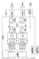
- FIG. 1 is a schematic diagram of a configuration of a lighting device according to the first embodiment.
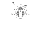
- FIG. 2 is a perspective view of an example of an optical combiner constituting the primary multiplexing unit shown in FIG.
- FIG. 3 is a cross-sectional view of an example of an optical combiner constituting the primary multiplexing unit shown in FIG.
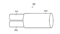
- FIG. 4 is a perspective view of an example of an optical combiner constituting the secondary multiplexing unit shown in FIG.
- FIG. 5 is a cross-sectional view of an example of an optical combiner constituting the secondary multiplexing unit shown in FIG.
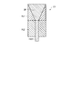
- FIG. 6 is a cross-sectional view of an example of the light conversion unit shown in FIG.
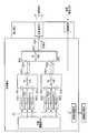
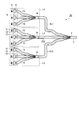
- FIG. 7 is a schematic configuration diagram of an endoscope according to the second embodiment.
- FIG. 1 is a schematic diagram of a configuration of a lighting device according to the first embodiment.
- FIG. 2 is a perspective view of an example of an optical combiner constituting the primary multiplexing unit shown in FIG.
- FIG. 8 is a timing chart of emission of the plurality of lasers shown in FIG.
- FIG. 9 is a schematic configuration diagram of an endoscope according to the third embodiment.
- FIG. 10 is a schematic diagram of the configuration of the optical coupler shown in FIG.
- FIG. 11 is a diagram of color space coordinates of the CIE 1976 L * u * v * color system.
- FIG. 12 is a diagram showing a combined light source disclosed in Japanese Patent Application Laid-Open No. 2007-41342.
- FIG. 1 is a schematic diagram of a configuration of a lighting device according to the first embodiment.
- the illumination device includes a plurality of lasers LS11 to LS13 and LS21 to LS23, which are narrow band light sources, a light source driving unit DR that controls driving of the lasers LS11 to LS13 and LS21 to LS23, and lasers LS11 to LS13 and LS21 to LS23, respectively.
- optical fibers FB11 to FB13, FB21 to FB23 connected to each other, optical combiners CB1 and CB2, which are primary multiplexing units connected to the optical fibers FB11 to FB13, and FB21 to FB23, and optical combiners CB1 and CB2, respectively.
- the optical conversion unit CV is provided.
- the amounts of emitted light and the emission wavelengths of the lasers LS11 to LS13 and LS21 to LS23 are as follows.
- the “outgoing light amount” indicates the maximum light amount used in this illumination device. Or the rated light quantity of each laser may be sufficient.
- Laser LS11 emitted light quantity 3W, emission wavelength 445nm (blue)
- Laser LS12 emitted light quantity 2W, emission wavelength 525nm (green)
- Laser LS13 emitted light quantity 1W, emission wavelength 635nm (red)
- Laser LS21 emitted light quantity 3W, emission wavelength 445nm (blue)
- Laser LS22 emitted light quantity 2W, emission wavelength 525nm (green)
- Laser LS23 emitted light quantity 1W, emission wavelength 635nm (red)
- the plurality of lasers LS11 to LS13 and LS21 to LS23 emit light of at least two same color regions with respect to the three color regions of the blue region, the green region, and the red region.
- a narrow band light source In the present embodiment, two lasers are included for each of the three color regions of the blue region, the green region, and the red region.
- the number of lasers and the amount of emitted light are not limited to this
- the blue region, green region, and red region described above are defined by the following wavelength regions.
- Each of the following wavelength regions is a wavelength region obtained by dividing the visible light region into three equal parts in the 400-700 nm wavelength region and then giving an overlapping region (overlap) of 20 nm.
- Red region 590-700nm
- a wavelength region of 400 nm or less and a wavelength region of 700 nm or more may be assigned to a blue region and a red region, respectively.
- the light source driving unit DR outputs a light source driving signal CS to each of the lasers LS11 to LS13, LS21 to LS23, and turns on / off each of the lasers LS11 to LS13, LS21 to LS23, a driving current, a driving method (continuous driving (CW ), Pulse drive, etc.) can be controlled independently for each of the lasers LS11 to LS13, LS21 to LS23.
- CW continuous driving
- Pulse drive etc.
- optical fibers FB11 to FB14, FB21 to FB24, FB31 The incident ends of the optical fibers FB11 to FB13 and FB21 to FB23 are optically connected to the lasers LS11 to LS13 and LS21 to LS23, respectively. Further, the emission ends of the optical fibers FB11 to FB13 and FB21 to FB23 are optically connected to the optical combiner CB1 that is the first primary multiplexing unit and the optical combiner CB2 that is the second primary multiplexing unit, respectively. Has been.
- the optical fibers FB11 to FB13 and FB21 to FB23 are constituted by, for example, single-wire multimode fibers having a core diameter of 50 ⁇ m to 200 ⁇ m.
- the lasers LS11 to LS13 and LS21 to LS23 and the optical fibers FB11 to FB13 and FB21 to FB23 are converged to be light.
- a plurality of coupling lenses for coupling to the fibers FB11 to FB13 and FB21 to FB23 are provided.
- the optical fiber FB11 guides the laser light emitted from the laser LS11 and is connected to the incident port IP11 of the optical combiner CB1.
- the optical fiber FB12 guides the laser light emitted from the laser LS12 and is connected to the incident port IP12 of the optical combiner CB1.
- the optical fiber FB13 guides the laser beam emitted from the laser LS13, and is connected to the incident port IP13 of the optical combiner CB1.
- the optical fiber FB21 guides the laser light emitted from the laser LS21 and is connected to the incident port IP21 of the optical combiner CB2.
- the optical fiber FB22 guides the laser light emitted from the laser LS22 and is connected to the incident port IP22 of the optical combiner CB2.
- the optical fiber FB23 guides the laser light emitted from the laser LS23 and is connected to the incident port IP23 of the optical combiner CB2.
- the incident ends of the optical fibers FB14 and FB24 are optically connected to the optical combiners CB1 and CB2, respectively.
- the emission ends of the optical fibers FB14 and FB24 are both optically connected to the optical combiner CB3 that is a secondary multiplexing unit.
- the optical fiber FB14 is connected to the output port OP11 of the optical combiner CB1, guides the first primary combined light that is the combined light of the laser light emitted from the lasers LS11 to LS13, and is a secondary combining unit. It is connected to the incident port IP31 of the optical combiner CB3.
- the optical fiber FB24 is connected to the output port OP21 of the optical combiner CB2, guides the second primary combined light that is the combined light of the laser beams emitted from the lasers LS21 to LS23, and is a secondary combining unit. It is connected to the incident port IP32 of the optical combiner CB3.
- the incident end of the optical fiber FB31 is optically connected to the optical combiner CB3.
- the emission end of the optical fiber FB31 is optically connected to the light conversion unit CV.
- the optical fiber FB31 is connected to the output port OP31 of the optical combiner CB3, and guides the secondary combined light that is the combined light of the first primary combined light and the second primary combined light to the light conversion unit CV. Optically connected.
- the optical fibers FB14, FB24, and FB31 are made of, for example, a single-wire multimode fiber having a core diameter of 100 ⁇ m to 400 ⁇ m.
- optical combiner CB1, CB2 (primary combiner)
- the optical combiners CB1 and CB2 have a function of multiplexing light incident on a plurality of incident ports IP11 to IP13 and IP21 to IP23.
- An example of the optical combiner CB1 in this embodiment is shown in FIGS.
- the optical combiner CB2 has a similar configuration.
- the optical combiner CB1 and the optical combiner CB2 have substantially the same characteristics.
- the optical combiner CB1 will be described.
- the optical combiner CB1 has three incident ports IP11 to IP13 and one output port OP11.
- the incident ports IP11 to IP13 are constituted by, for example, single-wire multimode fibers having a core diameter of 50 ⁇ m to 200 ⁇ m.
- the emission port OP11 is configured by a single-wire multimode fiber having a core diameter of 100 ⁇ m to 400 ⁇ m, for example.
- the core diameter of the exit port OP11 is larger than the core diameter of the entrance ports IP11 to IP13.
- the core region of the incident ports IP11 to IP13 is included with respect to the core region of the output port OP11.
- the optical combiner CB1 is manufactured by fusing the cores of the incident ports IP11 to IP13 and the core of the output port OP11. As a result, the light guided through the incident ports IP11 to IP13 is combined and output from the output port OP11. It has a function to do.
- the optical combiner CB1 has three incident ports IP11 to IP13 and an output port OP11.
- An optical fiber FB11 is connected to the incident port IP11, and the laser beam emitted from the laser LS11 is incident thereon.
- An optical fiber FB12 is connected to the incident port IP12, and the laser light emitted from the laser LS12 is incident thereon.
- An optical fiber FB13 is connected to the incident port IP13, and laser light emitted from the laser LS13 is incident thereon. From the emission port OP11, the first primary combined light that is the combined light of the laser light emitted from the lasers LS11 to LS13 is emitted.
- the emission port OP11 is connected to the optical fiber FB14.
- the optical combiner CB2 has three incident ports IP21 to IP23 and an output port OP21.
- An optical fiber FB21 is connected to the incident port IP21, and the laser light emitted from the laser LS21 is incident thereon.
- An optical fiber FB22 is connected to the incident port IP22, and the laser light emitted from the laser LS22 is incident thereon.
- An optical fiber FB23 is connected to the incident port IP23, and the laser light emitted from the laser LS23 is incident thereon. From the emission port OP21, the second primary combined light that is the combined light of the laser light emitted from the lasers LS21 to LS23 is emitted.
- the emission port OP21 is connected to the optical fiber FB24.
- optical combiner CB3 (secondary combiner)
- the optical combiner CB3 has a function of multiplexing light incident on the plurality of incident ports IP31 and IP32.
- An example of the optical combiner CB3 in the present embodiment is shown in FIGS.
- the optical combiner CB3 has two entrance ports IP31 and IP32 and an exit port OP31.
- the core diameter of the exit port OP31 is larger than the core diameter of the entrance ports IP31 and IP32. Further, in the cross section of the optical combiner CB3, the core regions of the incident ports IP31 and IP32 are included with respect to the core region of the output port OP31.
- the optical combiner CB3 has two incident ports IP31 and IP32 and an output port OP31.
- An optical fiber FB14 is connected to the incident port IP31, and the first primary combined light is incident thereon.
- An optical fiber FB24 is connected to the incident port IP32, and the second primary combined light is incident thereon.
- From the emission port OP31 secondary combined light that is a combined light of the first primary combined light and the second primary combined light is output.
- the emission port OP31 is connected to the optical fiber FB31.
- the light conversion unit CV has a function of converting the secondary combined light guided by the optical fiber FB31 into a desired light distribution.
- An example of the light conversion unit CV in the present embodiment is shown in FIG.
- the light conversion unit CV includes a diffusion member DF, a holder HL1 that holds the diffusion member DF, and a holder HL2 that holds the optical fiber FB31.
- the holder HL1 and the holder HL2 are fixed to each other, whereby the diffusion member DF and the optical fiber FB31 are optically connected.
- the diffusion member DF may be configured by a transparent member in which alumina particles or the like are dispersed.
- the diffusion member DF may also be constituted by a diffusion plate.
- the light conversion unit CV may be configured using a lens instead of the diffusion member DF, or may be configured by combining a lens and a diffusion member.
- the lasers LS11 to LS13 and LS21 to LS23 are grouped based on the amount of emitted light. These are grouped so that the lasers LS11 to LS13 and LS21 to LS23 having the same amount of emitted light are in the same group.
- lasers LS11 to LS13 and LS21 to LS23 in which the amount of emitted light is included in a predetermined range are grouped in the same group. In this case, for example, group 1 includes lasers with an emitted light amount of 2.5 W or more.
- Group 2 includes lasers with an emitted light quantity of 1.5 W or more and less than 2.5 W.
- Group 3 includes lasers with an emitted light quantity of less than 1.5 W.
- the laser LS11 and the laser LS21 have the same 3W emission light amount
- the laser LS12 and the laser LS22 have the same 2W emission light amount
- the laser LS13 and the laser LS23 have the same 1W emission light amount.
- Lasers LS11 to LS13 and LS21 to LS23 having the same amount of emitted light are grouped into the same group.
- “the same amount of emitted light” indicates that they are the same in design, and lasers having different amounts of emitted light of about several mW due to manufacturing variations are regarded as the same amount of emitted light.
- the lasers LS11 to LS13 and LS21 to LS23 are grouped as follows.
- Lasers LS11, LS21 and LS12, LS22 and LS13, and LS23 belonging to the same group are connected to the optical combiners CB1 and CB2, respectively, so that the amount of incident light is dispersed.
- each of a plurality of lasers LS11, LS21 and LS12, LS22 and LS13, and LS23 belonging to the same group includes a plurality of lasers LS11, LS21 and LS12, LS22 and LS13, and LS23 belonging to the same group. It is connected to any one of a plurality of optical combiners CB1 and CB2 so as to be distributed to CB2.
- the lasers LS11, LS21 and LS12, LS22 and LS13, and LS23 belonging to the same group have an optical combiner CB1 so that the light amount difference between the first primary combined light and the second primary combined light is not more than a predetermined value. , CB2.
- the same number of lasers LS11, LS21 and LS12, LS22, LS13, and LS23 belonging to the same group are distributed to the optical combiners CB1 and CB2.
- the lasers LS11 to LS13 and LS21 to LS23 are distributed to the optical combiners CB1 and CB2, as shown in Table 1.
- the difference in the amount of light incident on the optical combiner CB1 and the optical combiner CB2 is the smallest (in this case, it is substantially equal).
- the light amount difference between the first primary combined light and the second primary combined light is the smallest (in this case, approximately equal). Become).
- the number of lasers and / or the amount of emitted light are not limited to those shown in this embodiment.
- all the lasers may have different emission wavelengths, all the lasers may have different amounts of emitted light, the number of lasers in each color region may be different, or each color region These lasers may have different emission wavelengths.
- an orange laser or a purple laser may be used.
- the light source is not limited to a laser, but may be a narrow band light source, and may be a narrow band light source such as an LED.
- a single light source that emits laser light and LED light having a plurality of wavelengths, and a light source that selectively cuts out narrow-band light from a broadband light emitted by a xenon lamp or the like by a filter.
- the light quantity difference between the incident lights to the optical combiner CB1 and the optical combiner CB2 or the light quantity difference between the first primary combined light and the second primary combined light is most preferably distributed.
- the light amount difference between the incident light to the optical combiner CB1 and the optical combiner CB2 may be a light amount difference of 50% or less with respect to the sum of the incident light amount to the optical combiner CB1 and the incident light amount to the optical combiner CB2.
- the light amount difference between the first primary combined light and the second primary combined light is 50% or less with respect to the sum of the first primary combined light amount and the second primary combined light amount.
- the light amount difference may be any. Furthermore, it is more desirable if it is 20% or less. With this light amount difference, as will be described later, heat generated in the secondary multiplexing unit is dispersed, and failure of the secondary multiplexing unit can be prevented.
- Laser light emitted from the lasers LS11 to LS13 is guided through the optical fibers FB11 to FB13, and then enters the optical combiner CB1 from the incident ports IP11 to IP13. From the emission port OP11 of the optical combiner CB1, the first primary combined light that is the combined light of the laser lights emitted from the lasers LS11 to LS13 is emitted.
- the first primary combined light is white light.
- Laser light emitted from the lasers LS21 to LS23 is guided through the optical fibers FB21 to FB23, and then enters the optical combiner CB2 from the incident ports IP21 to IP23. From the emission port OP21 of the optical combiner CB2, the second primary combined light that is the combined light of the laser light emitted from the lasers LS21 to LS23 is emitted.
- the second primary combined light is white light.
- the first primary combined light is guided through the optical fiber FB21 and then enters the optical combiner CB3 from the incident port IP31.
- the second primary combined light is guided through the optical fiber FB22 and then enters the optical combiner CB3 from the incident port IP32.
- a secondary combined light that is a combined light of the first primary combined light and the second primary combined light is output from the output port OP31 of the optical combiner CB3.
- the secondary combined light is white light.
- the second-order combined light is guided through the optical fiber FB31 and then enters the light conversion unit CV.
- the secondary combined light is converted into a desired light distribution by the light conversion unit CV and then emitted as illumination light IL.
- the plurality of lasers LS11 to LS13 and LS21 to LS23 are grouped based on the amount of emitted light, and the laser beams emitted from the plurality of lasers LS11 to LS13 and LS21 to LS23 are incident on the optical combiners CB1 and CB2.
- optical loss is dispersed in the optical path between the incident port IP31 and the outgoing port OP31 and the optical path between the incident port IP32 and the outgoing port OP31 in the optical combiner CB3.
- Heat generation is dispersed. That is, it is possible to prevent heat generation from being concentrated only on a part of the internal optical path of the optical combiner CB3. As a result, failure due to heat generation of the optical combiner CB3 can be prevented.
- This modification is an example of a connection configuration of a laser and an optical combiner when the number of lasers and the amount of emitted light are different.
- the number of lasers is changed, and accordingly, the number of incident ports of the optical combiners CB1 and CB2 is also changed.
- the illumination device of this modification has nine lasers LS11 to LS14, LS21 to LS25, which are not shown.
- the laser LS11 and the laser LS21 have the same emission wavelength of 445 nm with the same amount of emitted light of 3 W
- the laser LS12, the laser LS13, and the laser LS22 have the same emission wavelength of 525 nm with the same amount of emitted light of 2 W
- the laser LS14 The laser LS24 and the laser LS2 have the same amount of emitted light of 1 W and an emission wavelength of 635 nm.
- the lasers LS11 to LS14 and LS21 to LS25 are grouped as follows.
- Group 1 Lasers LS11 and LS21
- Group 2 Lasers LS12, LS13, LS22, LS23
- Group 3 Lasers LS14, LS24, LS25
- the lasers LS11 to LS14 and LS21 to LS25 are distributed to the optical combiners CB1 and CB2.
- the amount of light incident on the optical combiner CB1 is 8W
- the amount of light incident on the optical combiner CB2 is 9W
- the difference in the amount of light is 1W. This is about 5.9% and 20% or less with respect to the sum 17W of the incident light quantity to the optical combiner CB1 and the incident light quantity to the optical combiner CB2.
- L be the number of primary multiplexing parts (L ⁇ 1).
- M the number of incident ports of each primary multiplexing unit
- M the number of incident ports of each primary multiplexing unit
- N the number of incident ports of the secondary multiplexing unit (N ⁇ 2).
- a light amount range between the emitted light amount of the first laser having the largest emitted light amount and the emitted light amount of the K-th laser having the smallest emitted light amount is divided into groups at substantially equal intervals.
- the first laser When the emitted light quantity of the first laser having the largest emitted light quantity is larger than the sum of the emitted light quantities of the other lasers, the first laser is not subject to grouping and is not connected to the primary multiplexing unit. Connect directly to the secondary multiplexer. In this case, L ⁇ N.
- Distribution method A plurality of lasers belonging to the same group are distributed to a plurality of primary multiplexing units so that a light amount difference between a plurality of primary combined lights emitted from the plurality of primary multiplexing units is small.
- “distribution” indicates that connection is made so that the amounts of laser light emitted from a plurality of lasers are dispersedly incident on a plurality of primary multiplexing units.
- Distribution is performed first from the group in which the average emitted light quantity of the laser included in the group is large. (Although the number of incident ports of each primary multiplexing unit is all equal, if the number of incident ports of a plurality of primary multiplexing units is not all equal, compared to the other primary multiplexing units. (If the number of the incident ports is small and the incident port is filled with the laser first, the distribution is performed by excluding the first multiplexing portion.)
- a plurality of lasers belonging to the same group are distributed to the plurality of primary multiplexing units so that the difference in the number of lasers distributed to the plurality of primary multiplexing units in the same group is 1 or less.
- the surplus is zero, and the same number is distributed to each multiplexing unit, and a plurality of first-order multiplexing signals are included in the same group.
- the difference in the number of lasers distributed to the part is zero.
- the same number of L or multiples of L lasers are distributed in order from the laser having the largest emitted light amount to each primary multiplexing unit, and the remaining laser beams are emitted in the first distribution. Is distributed preferentially from the first-order multiplexing unit to which the smaller laser is distributed.
- the second embodiment is an endoscope having the illumination device in the first embodiment.
- FIG. 7 is a schematic configuration diagram of an endoscope according to the second embodiment.
- the endoscope has a main body portion BD and an insertion portion IS, the light conversion portion CV of the illumination device is disposed in the insertion portion IS, and the elements of the illumination device excluding the light conversion portion CV and the optical fiber FB31 are the main body portion.
- the optical fiber FB31 is arranged in both the main body portion BD and the insertion portion IS.
- the endoscope includes an imaging unit IM that images the observation body, an image processing unit PR that processes an imaging signal from the imaging unit IM and generates an image of the observation body, and an image processing unit PR.
- An image display unit DS that displays the generated image of the observation body is provided.
- the lasers LS11 to LS13 and LS21 to LS23 do not emit laser beams simultaneously, and the lasers LS11 to LS13 and LS21 to LS23 in the blue region, the green region, and the red region emit laser beams sequentially. Further, in the present embodiment, the grouping standard and distribution method for the plurality of lasers LS11 to LS13 and LS21 to LS23 are different from those of the first embodiment.
- Imaging unit IM detects reflected / scattered light RL from the observation body and generates an imaging signal.
- the imaging signal is output to the image processing unit PR.
- the imaging unit IM is, for example, a CCD imager or a CMOS imager. Further, the imaging unit IM in the present embodiment is a monochrome imager that does not have a color filter.
- the image processing unit PR performs predetermined image processing on the B imaging signal, the G imaging signal, and the R imaging signal that are sequentially output from the imaging unit IM, and generates an image of the observation body.
- the image display unit DS displays the image generated by the image processing unit PR.
- the image display unit DS is a monitor such as a liquid crystal display.
- the lasers LS11 to LS13 and LS21 to LS23 are grouped based on the emission timing. These are grouped so that the lasers LS11 to LS13 and LS21 to LS23 having the same emission timing are in the same group.
- FIG. 8 shows a timing chart of emission of the lasers LS11 to LS13 and LS21 to LS23 in the present embodiment.
- the laser LS11 and the laser LS21 have the same amount of emitted light of 3 W, and emit laser light in the blue region at the same timing t1.
- the laser LS12 and the laser LS22 have the same amount of emitted light of 2 W, and emit laser light in the green region at the same timing t2.
- the laser LS13 and the laser LS23 have the same amount of emitted light of 1 W, and emit laser light in the red region at the same timing t3.
- the lasers LS11 to LS13 and LS21 to LS23 are grouped as follows.
- Lasers LS11, LS21 and LS12, LS22 and LS13, and LS23 belonging to the same group are distributed to the optical combiners CB1 and CB2, respectively, so as to disperse the incident light amount, as in the first embodiment.
- the lasers LS11, LS21 and LS12, LS22 and LS13, and LS23 belonging to the same group have an optical combiner so that the light amount difference between the first primary combined light and the second primary combined light is not more than a predetermined value.
- the same number of lasers LS11, LS21 and LS12, LS22, LS13, and LS23 belonging to the same group are distributed to the optical combiners CB1 and CB2, respectively.
- the lasers LS11 to LS13 and LS21 to LS23 are distributed to the optical combiners CB1 and CB2, as shown in Table 3.
- the difference in the amount of light incident on the optical combiner CB1 and the optical combiner CB2 is the smallest (in this case, it is substantially equal).
- the light amount difference between the first primary combined light and the second primary combined light is the smallest (in this case, Almost equal).
- having the same emission timing includes the meaning of having a period of emission at the same time. That is, when the emission start timing is not the same time, or when the emission times are different, even if the emission times are different, they have the same emission timing.
- the number of lasers and / or the emission timing are not limited to those shown in this embodiment.
- the number of lasers that emit laser light at each emission timing is not limited to two.
- lasers that emit laser light at the same timing are not necessarily those having the same emission wavelength.
- an orange laser or a purple laser may be used.
- blue, green, and red lasers are sequentially emitted corresponding to three subframes, but the number of subframes is not limited to three.
- the laser LS11 and the laser LS21 emit laser light in the blue region at the same time.
- the laser light emitted from the laser LS11 is guided through the optical fiber FB11, is incident on the optical combiner CB1 from the incident port IP11, and is emitted from the emission port OP11 of the optical combiner CB1.
- the laser light emitted from the laser LS21 is guided through the optical fiber FB21, is incident on the optical combiner CB2 from the incident port IP21, and is emitted from the emission port OP21 of the optical combiner CB2.
- the laser light emitted from the laser LS11 and the laser light emitted from the laser LS21 are respectively incident on the incident port IP31 and the incident port IP32 of the optical combiner CB3, and the laser light emitted from the laser LS11 is emitted from the emission port OP31.
- the combined light of the laser light emitted from the laser LS21 is emitted.
- the combined light of the laser light emitted from the laser LS11 and the laser light emitted from the laser LS21 is converted into a desired light distribution by the light conversion unit CV, and then irradiated to the observation body as illumination light IL.
- the imaging unit IM detects the reflected scattered light RL of the illumination light IL generated by the observation body and generates an imaging signal of the subframe 1.
- the laser LS12 and the laser LS22 emit laser light in the green region at the same time.
- the combined light of the laser light emitted from the laser LS12 and the laser light emitted from the laser LS22 is converted into a desired light distribution by the light conversion unit CV in the same manner as described above, and then emitted as the illumination light IL.
- the object is irradiated.
- the imaging unit IM detects the reflected and scattered light RL of the illumination light IL generated by the observation body and generates an imaging signal of the subframe 2.
- the laser LS13 and the laser LS23 emit laser light in the red region at the same time.
- the combined light of the laser light emitted from the laser LS13 and the laser light emitted from the laser LS23 is converted into a desired light distribution by the light conversion unit CV in the same manner as described above, and then emitted as the illumination light IL.
- the object is irradiated.
- the imaging unit IM detects the reflected scattered light RL of the illumination light IL generated by the observation body and generates an imaging signal of the subframe 3.
- the image processing unit PR combines the images of the subframes 1 to 3 to generate a color (white) image of one frame.
- the image display unit DS displays the image generated by the image processing unit PR.
- the plurality of lasers LS11 to LS13 and LS21 to LS23 are grouped based on the emission timing, and the laser beams emitted from the plurality of lasers LS11 to LS13 and LS21 to LS23 are incident on the optical combiners CB1 and CB2.
- optical loss is temporally caused in the optical path between the entrance port IP31 and the exit port OP31 and in the optical path between the entrance port IP32 and the exit port OP31 in the optical combiner CB3.
- the third embodiment is an endoscope similarly to the second embodiment.
- FIG. 9 is a schematic configuration diagram of an endoscope according to the third embodiment.
- the optical combiner CB3 that is the secondary multiplexing unit of the illumination device is replaced with the optical coupler CP.
- the fiber FB31 and the light conversion unit CV are replaced with two optical fibers FB41 and FB42 and two light conversion units CV1 and CV2.
- the imaging unit IM is composed of a color imager.
- optical coupler CP (secondary multiplexing unit, optical multiplexing / demultiplexing unit)
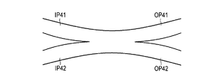
- An example of the optical coupler CP in the present embodiment is shown in FIG.
- the optical coupler CP has two incident ports IP41 and IP42 and two outgoing ports OP41 and OP42.
- the optical coupler CP has a function of multiplexing the light incident on the incident port IP41 and the light incident on the incident port IP42 and demultiplexing the combined light to the output port OP41 and the output port OP42.
- the optical coupler CP ideally splits the light incident on the incident port IP41 into the outgoing port OP41 and the outgoing port OP42 at a ratio of 1: 1, and ideally converts the light incident on the incident port IP42 to 1 Branches to the exit port OP41 and the exit port OP42 at a ratio of 1.
- An optical fiber FB14 is connected to the incident port IP41, and the first primary combined light is incident thereon.
- An optical fiber FB24 is connected to the incident port IP42, and the second primary combined light is incident thereon. From the emission port OP41, the first secondary combined light obtained by combining the first primary combined light and the second primary combined light is output. From the incident port IP42, a second secondary combined light obtained by combining the first primary combined light and the second primary combined light is emitted.
- optical fibers FB41 and FB42 The incident end of the optical fiber FB41 is connected to the emission port OP41 of the optical coupler CP, and the emission end of the optical fiber FB41 is connected to the light conversion unit CV1.
- the incident end of the optical fiber FB42 is connected to the emission port OP42 of the optical coupler CP, and the emission end of the optical fiber FB42 is connected to the light conversion unit CV2.
- Each of the optical fibers FB41 and FB42 has substantially the same characteristics as the optical fiber FB31 of the second embodiment, that is, the optical fiber FB31 of the first embodiment.
- Both the light conversion units CV1 and CV2 are arranged at the distal end portion of the insertion portion IS of the endoscope, like the light conversion unit CV of the second embodiment.
- Each of the light conversion units CV1 and CV2 has substantially the same characteristics as the light conversion unit CV of the second embodiment, that is, the light conversion unit CV of the first embodiment.
- the light conversion unit CV1 converts the secondary combined light incident from the optical fiber FB41 into a desired light distribution and emits it as illumination light IL1.
- the light conversion unit CV2 converts the secondary combined light incident from the optical fiber FB42 into a desired light distribution and emits it as illumination light IL2.
- the third embodiment differs from the second embodiment in grouping criteria and distribution methods for the plurality of lasers LS11 to LS13 and LS21 to LS23. Further, the lasers LS11 to LS13 and LS21 to LS23 emit laser beams at the same time as in the first embodiment. In the present embodiment, the lasers LS11 to LS13 and LS21 to LS23 have the same amount of emitted light of 1W.
- the branching ratio of the optical coupler CP is designed to be approximately 1: 1, the branching ratio may deviate from the design value due to manufacturing errors.
- the branching ratio of the optical coupler CP to the outgoing port OP41 and the outgoing port OP42 can be biased to the branching ratio as 1.1: 0.9.
- the branching ratio of the optical coupler CP to the output port OP41 and the output port OP42 is 0.9: 1.1. The opposite branching ratio will occur.
- the first light output from the output port OP41 if there is a color difference between the first primary combined light incident on the incident port IP41 and the second primary combined light incident on the incident port IP42, the first light output from the output port OP41.
- the color difference between the second combined light and the second second combined light emitted from the emission port OP42 becomes larger. Accordingly, the color difference between the illumination light IL1 emitted from the light conversion unit CV1 and the illumination light IL2 emitted from the light conversion unit CV2 also increases.
- the total illumination light which is a superposition of the illumination light IL1 and the illumination light IL2 differs in color due to the light distribution, that is, the illumination light has uneven color, which may adversely affect the observation. .
- the lasers LS11 to LS13 and LS21 to LS23 are grouped based on the emission wavelength, and lasers having emission wavelengths included in a predetermined wavelength range are grouped in the same group.
- the predetermined wavelength range is each color region of the blue region, the green region, and the red region defined in the first embodiment. That is, narrow band light sources having emission wavelengths included in the same color region are grouped into the same group.
- the laser LS11 and the laser LS21 have the same emission wavelength of 445 nm
- the laser LS12 and the laser LS22 have the same emission wavelength of 525 nm
- the laser LS13 and the laser LS23 have the same emission wavelength of 635 nm.
- Lasers LS having the same emission wavelength are grouped into the same group.
- “the same emission wavelength” indicates that they are the same in design, and it is considered that lasers having different emission wavelengths by about several nm due to manufacturing variations or the like have the same emission wavelength.
- the lasers LS11 to LS13 and LS21 to LS23 are grouped as follows.
- Lasers LS11, LS21 and LS12, LS22 and LS13, and LS23 belonging to the same group have optical combiners CB1 and CB1 so that the color difference between the first primary combined light and the second primary combined light is not more than a predetermined value, respectively.
- CB1 and CB1 so that the color difference between the first primary combined light and the second primary combined light is not more than a predetermined value, respectively.
- the lasers LS11, LS21 and LS12, LS22 and LS13, and LS23 belonging to the same group are distributed to the optical combiners CB1 and CB2 so that the color difference between the illumination light IL1 and the illumination light IL2 is not more than a predetermined value.
- the same number of lasers LS11, LS21 and LS12, LS22, LS13, and LS23 belonging to the same group are distributed to the optical combiners CB1 and CB2.
- the lasers LS11 to LS13 and LS21 to LS23 are distributed to the optical combiners CB1 and CB2, as shown in Table 4.
- the color difference between the first primary combined light and the second primary combined light incident on the optical coupler CP is the smallest (in this case, approximately equal).
- the color difference between the illumination light IL1 and the illumination light IL2 is the smallest (in this case, approximately the same).
- the color difference in the present embodiment indicates “light color difference”.
- a difference in center wavelength can be used as the evaluation value of the color difference.
- the center wavelength ⁇ c is defined by the following equation (1), where Pi is the emitted light quantity of the laser and ⁇ i is the emission wavelength.
- the distance of the color space coordinates of the CIE 1976 L * u * v * color system shown in FIG. 11 may be used.
- the difference between the center wavelengths may be, for example, 50 nm or less.
- the distance of the color space coordinates for example, the following equation (2) may be 0.3 or less.
- the color difference between the illumination light IL1 emitted from the light conversion unit CV1 and the illumination light IL2 emitted from the light conversion unit CV2 is small, and the color has substantially uniform illumination characteristics.
- An endoscope can be provided.
- the embodiment is not limited thereto.
- the lasers LS11 to LS13 and LS21 to LS23 included in the same color region may be connected to the optical combiners CB1 and CB2.
- the number of lasers and / or the emission wavelength are not limited to those shown in this embodiment.
- all lasers may have different emission wavelengths.
- an orange laser or a purple laser may be used.
- the light source is not limited to a laser, and may be a narrow-band light source, and may be a narrow-band light source such as an LED.
- Laser light emitted from the lasers LS11 to LS13 is guided through the optical fibers FB11 to FB13, and then enters the optical combiner CB1 from the incident ports IP11 to IP13. From the emission port OP11 of the optical combiner CB1, the first primary combined light that is the combined light of the laser lights emitted from the lasers LS11 to LS13 is emitted.
- the first primary combined light is white light.
- Laser light emitted from the lasers LS21 to LS23 is guided through the optical fibers FB21 to FB23, and then enters the optical combiner CB2 from the incident ports IP21 to IP23. From the emission port OP21 of the optical combiner CB2, the second primary combined light that is the combined light of the laser light emitted from the lasers LS21 to LS23 is emitted.
- the second primary combined light is white light.
- the first primary combined light is guided through the optical fiber FB21 and then enters the optical coupler CP from the incident port IP41.
- the second primary combined light is guided through the optical fiber FB22 and then enters the optical coupler CP from the incident port IP42.
- a second-order combined light that is a combined light of the first first-order combined light and the second first-order combined light is output.
- the secondary combined light is white light.
- the second-order combined light is guided through the optical fiber FB31 and then enters the light conversion unit CV.
- the second-order combined light is converted into a desired light distribution by the light conversion units CV1 and IL2, and then emitted as illumination light IL1 and IL2, and irradiated on the observation body.
- the imaging unit IM detects reflected / scattered light RL of the illumination lights IL1 and IL2 generated by the observation body and generates an imaging signal.
- the image processing unit PR processes the imaging signal supplied from the imaging unit IM to generate an image.
- the image display unit DS displays the image generated by the image processing unit PR.
- the plurality of lasers LS11 to LS13 and LS21 to LS23 are grouped based on the emission wavelength, and the color difference between the first primary combined light and the second primary combined light is compared with the optical combiners CB1 and CB2.
- the color difference between the illumination light IL1 and the illumination light IL2 can be suppressed to be lower than the predetermined value. Thereby, the occurrence of uneven color of the illumination light is reduced, which contributes to good observation.
- the number of narrow-band light sources is not limited to the number of lasers in the embodiment described here, and may be appropriately changed.
- the lighting device includes at least four narrowband light sources, a plurality of primary multiplexing units that respectively combine the narrowband lights emitted from at least two of the at least four narrowband light sources, and their primary
- the configuration may include one secondary multiplexing unit that combines the primary combined light combined by the multiplexing unit.
- the illumination device may have a configuration in which the laser LS13 and the laser LS23 are omitted from the illumination device of the first embodiment.
- the illumination device includes at least three narrow band light sources, at least one primary multiplexing unit that multiplexes narrow band light emitted from at least two of the at least three narrow band light sources, and the primary.
- a first-order combined portion that combines the first-order combined light combined by the combining portion and the narrow-band light emitted from the narrow-band light source excluding the at least two narrow-band light sources. It may be a configuration.
- the lighting device of the first embodiment may be configured such that the laser LS13, the laser LS22, and the laser LS23 are omitted, and the optical combiner CB2 is omitted.
Landscapes
- Physics & Mathematics (AREA)
- General Physics & Mathematics (AREA)
- Optics & Photonics (AREA)
- Condensed Matter Physics & Semiconductors (AREA)
- Electromagnetism (AREA)
- Astronomy & Astrophysics (AREA)
- Semiconductor Lasers (AREA)
- Optical Couplings Of Light Guides (AREA)
- Instruments For Viewing The Inside Of Hollow Bodies (AREA)
- Non-Portable Lighting Devices Or Systems Thereof (AREA)
- Endoscopes (AREA)
Abstract
照明装置は、少なくとも4つの狭帯域光源(LS11~LS13,LS21~LS23)と、前記狭帯域光源の少なくとも2つから出射された狭帯域光をそれぞれ合波する複数の1次合波部(CB1,CB2)と、前記複数の1次合波部によって合波された1次合波光を合波する1つの2次合波部(CB3;CP)を有し、前記2次合波部によって合波された2次合波光を照明光として出射する。前記複数の狭帯域光源は、出射光量と発光波長と出射タイミングの少なくとも1つを含む照明特性をグルーピングの基準として、前記照明特性において所定の条件を満たす狭帯域光源が同じグループに含まれるように、複数のグループにグルーピングされている。同じグループに属する複数の狭帯域光源は、それらの狭帯域光源から出射された狭帯域光が前記複数の1次合波部に分配されるように前記複数の1次合波部に接続されている。
Description
本発明は、照明装置に関する。
特開2007-41342号公報は、高出力・高輝度な照明光を得るために複数の光源の出射光を2段階で合波する合波光源を開示している。図12は、その合波光源100を示している。合波光源100は、複数の光源11と、複数の光源11にそれぞれ対応して配置された複数のレンズ12と、複数の光源11からそれぞれ出射された光が複数のレンズ12を介してそれぞれ入射される複数のマルチモード光ファイバ13と、複数のマルチモード光ファイバ13のいくつかが一体化されて形成された第1ファイバ合波器14(1次合波部)と、第1ファイバ合波器14によって合波された第1の合波光を出射するマルチモード光ファイバ15-1,15-2,15-3を有する3つのファイバ合波光源ユニット1-1,1-2,1-3と、マルチモード光ファイバ15-1,15-2,15-3が一体化されて形成された第2ファイバ合波器2(2次合波部)と、第2ファイバ合波器2の出射端に接続され、第2の合波光を出射するマルチモード光ファイバ3を備えている。
各ファイバ合波光源ユニット1-1,1-2,1-3において、複数の光源11から出射された光は1つの第1ファイバ合波器14において合波されて第1の合波光となる。ファイバ合波光源ユニット1-1,1-2,1-3において生成された第1の合波光は、マルチモード光ファイバ15-1,15-2,15-3によって導波され、第2ファイバ合波器2において合波されて第2の合波光となる。これにより、複数の光源から出射された光を2段階で合波して高出力・高輝度な照明光を得ている。
第2ファイバ合波器2には大量の光が入射されるため、第2ファイバ合波器2に接続されたマルチモード光ファイバ15-1,15-2,15-3によってそれぞれ導光される第1の合波光に光量の偏りがあると、第2ファイバ合波器2とマルチモード光ファイバ15-1,15-2,15-3の光結合部、および/または、マルチモード光ファイバ15-1,15-2,15-3のそれぞれに対応する第2ファイバ合波器2の内部光路において、一部分に光吸収による発熱が集中して第2ファイバ合波器2の故障の原因となる虞がある。
本発明の目的は、2次合波部内における一部分に集中した発熱の発生が抑えられた照明装置を提供することである。
照明装置は、少なくとも4つの狭帯域光源と、前記狭帯域光源の少なくとも2つから出射された狭帯域光をそれぞれ合波する複数の1次合波部と、前記複数の1次合波部によって合波された1次合波光を合波する2次合波部を有し、前記2次合波部によって合波された2次合波光を照明光として出射する。前記複数の狭帯域光源は、前記狭帯域光の照明特性をグルーピングの基準として、前記照明特性において所定の条件を満たす狭帯域光源が同じグループに含まれるように、複数のグループにグルーピングされている。同じグループに属する複数の狭帯域光源の各々は、前記同じグループに属する複数の狭帯域光源の狭帯域光源が前記複数の1次合波部に分配されるように前記複数の1次合波部のいずれか1つに接続されている。
本発明によれば、2次合波部内における一部分に集中した発熱の発生が抑えられた照明装置が提供される。
<第1実施形態>
[構成]
図1は、第1実施形態における照明装置の構成模式図である。照明装置は、狭帯域光源である複数のレーザLS11~LS13,LS21~LS23と、レーザLS11~LS13,LS21~LS23の駆動を制御する光源駆動部DRと、レーザLS11~LS13,LS21~LS23にそれぞれ接続された複数の光ファイバFB11~FB13,FB21~FB23と、光ファイバFB11~FB13,FB21~FB23と接続された1次合波部である光コンバイナCB1,CB2と、光コンバイナCB1,CB2にそれぞれ接続された複数の光ファイバFB14,FB24と、光ファイバFB14,FB24と接続された2次合波部である光コンバイナCB3と、光コンバイナCB3に接続された光ファイバFB31と、光ファイバFB31と接続された光変換部CVを有している。
[構成]
図1は、第1実施形態における照明装置の構成模式図である。照明装置は、狭帯域光源である複数のレーザLS11~LS13,LS21~LS23と、レーザLS11~LS13,LS21~LS23の駆動を制御する光源駆動部DRと、レーザLS11~LS13,LS21~LS23にそれぞれ接続された複数の光ファイバFB11~FB13,FB21~FB23と、光ファイバFB11~FB13,FB21~FB23と接続された1次合波部である光コンバイナCB1,CB2と、光コンバイナCB1,CB2にそれぞれ接続された複数の光ファイバFB14,FB24と、光ファイバFB14,FB24と接続された2次合波部である光コンバイナCB3と、光コンバイナCB3に接続された光ファイバFB31と、光ファイバFB31と接続された光変換部CVを有している。
〔レーザLS11~LS13,LS21~LS23(狭帯域光源)〕
各レーザLS11~LS13,LS21~LS23の出射光量および発光波長は以下の通りである。ここにおいて「出射光量」とは、この照明装置で用いる最大光量を示している。または、各レーザの定格光量であってもよい。
・レーザLS11:出射光量3W、発光波長445nm(青)
・レーザLS12:出射光量2W、発光波長525nm(緑)
・レーザLS13:出射光量1W、発光波長635nm(赤)
・レーザLS21:出射光量3W、発光波長445nm(青)
・レーザLS22:出射光量2W、発光波長525nm(緑)
・レーザLS23:出射光量1W、発光波長635nm(赤)
高出力の照明光ILを出射するために、複数のレーザLS11~LS13,LS21~LS23は、青色領域・緑色領域・赤色領域の3つの色領域に対して、少なくとも2つの同じ色領域の発光波長を有する狭帯域光源を含んでいる。
本実施形態においては、青色領域・緑色領域・赤色領域の3つの色領域に対してそれぞれ2つのレーザを含んでいる。ただし、レーザの数および出射光量はこれに限らない。
各レーザLS11~LS13,LS21~LS23の出射光量および発光波長は以下の通りである。ここにおいて「出射光量」とは、この照明装置で用いる最大光量を示している。または、各レーザの定格光量であってもよい。
・レーザLS11:出射光量3W、発光波長445nm(青)
・レーザLS12:出射光量2W、発光波長525nm(緑)
・レーザLS13:出射光量1W、発光波長635nm(赤)
・レーザLS21:出射光量3W、発光波長445nm(青)
・レーザLS22:出射光量2W、発光波長525nm(緑)
・レーザLS23:出射光量1W、発光波長635nm(赤)
高出力の照明光ILを出射するために、複数のレーザLS11~LS13,LS21~LS23は、青色領域・緑色領域・赤色領域の3つの色領域に対して、少なくとも2つの同じ色領域の発光波長を有する狭帯域光源を含んでいる。
本実施形態においては、青色領域・緑色領域・赤色領域の3つの色領域に対してそれぞれ2つのレーザを含んでいる。ただし、レーザの数および出射光量はこれに限らない。
(色領域)
上記した青色領域・緑色領域・赤色領域は、以下の波長領域で定義される。以下の各波長領域は、可視光領域のうち、400-700nmの波長領域において、3等分したうえで、20nmの重なり領域(オーバーラップ)をもたせた波長領域である。
・青色領域:400-510nm
・緑色領域:490-610nm
・赤色領域:590-700nm
また、例えば、400nm以下の波長領域と700nm以上の波長領域はそれぞれ青色領域と赤色領域に割り当てられてもよい。
上記した青色領域・緑色領域・赤色領域は、以下の波長領域で定義される。以下の各波長領域は、可視光領域のうち、400-700nmの波長領域において、3等分したうえで、20nmの重なり領域(オーバーラップ)をもたせた波長領域である。
・青色領域:400-510nm
・緑色領域:490-610nm
・赤色領域:590-700nm
また、例えば、400nm以下の波長領域と700nm以上の波長領域はそれぞれ青色領域と赤色領域に割り当てられてもよい。
〔光源駆動部DR〕
光源駆動部DRは、各レーザLS11~LS13,LS21~LS23に対して光源駆動信号CSを出力し、各レーザLS11~LS13,LS21~LS23のON/OFF、駆動電流、駆動方式(連続駆動(CW)、パルス駆動など)を各レーザLS11~LS13,LS21~LS23に対して独立に制御可能である。
光源駆動部DRは、各レーザLS11~LS13,LS21~LS23に対して光源駆動信号CSを出力し、各レーザLS11~LS13,LS21~LS23のON/OFF、駆動電流、駆動方式(連続駆動(CW)、パルス駆動など)を各レーザLS11~LS13,LS21~LS23に対して独立に制御可能である。
〔光ファイバFB11~FB14,FB21~FB24,FB31〕
光ファイバFB11~FB13,FB21~FB23の入射端は、それぞれ、レーザLS11~LS13,LS21~LS23と光学的に接続されている。また、光ファイバFB11~FB13,FB21~FB23の出射端は、それぞれ、第1の1次合波部である光コンバイナCB1と第2の1次合波部である光コンバイナCB2と光学的に接続されている。
光ファイバFB11~FB13,FB21~FB23の入射端は、それぞれ、レーザLS11~LS13,LS21~LS23と光学的に接続されている。また、光ファイバFB11~FB13,FB21~FB23の出射端は、それぞれ、第1の1次合波部である光コンバイナCB1と第2の1次合波部である光コンバイナCB2と光学的に接続されている。
光ファイバFB11~FB13,FB21~FB23は、例えば、コア径50μm~200μmの単線のマルチモードファイバで構成されている。図示されていないが、レーザLS11~LS13,LS21~LS23と光ファイバFB11~FB13,FB21~FB23の間には、それぞれ、レーザLS11~LS13,LS21~LS23から射出されたレーザ光を収束させて光ファイバFB11~FB13,FB21~FB23に結合するための複数の結合レンズが設けられている。
光ファイバFB11は、レーザLS11から出射されたレーザ光を導光し、光コンバイナCB1の入射ポートIP11に接続されている。
光ファイバFB12は、レーザLS12から出射されたレーザ光を導光し、光コンバイナCB1の入射ポートIP12に接続されている。
光ファイバFB13は、レーザLS13から出射されたレーザ光を導光し、光コンバイナCB1の入射ポートIP13に接続されている。
光ファイバFB21は、レーザLS21から出射されたレーザ光を導光し、光コンバイナCB2の入射ポートIP21に接続されている。
光ファイバFB22は、レーザLS22から出射されたレーザ光を導光し、光コンバイナCB2の入射ポートIP22に接続されている。
光ファイバFB23は、レーザLS23から出射されたレーザ光を導光し、光コンバイナCB2の入射ポートIP23に接続されている。
光ファイバFB12は、レーザLS12から出射されたレーザ光を導光し、光コンバイナCB1の入射ポートIP12に接続されている。
光ファイバFB13は、レーザLS13から出射されたレーザ光を導光し、光コンバイナCB1の入射ポートIP13に接続されている。
光ファイバFB21は、レーザLS21から出射されたレーザ光を導光し、光コンバイナCB2の入射ポートIP21に接続されている。
光ファイバFB22は、レーザLS22から出射されたレーザ光を導光し、光コンバイナCB2の入射ポートIP22に接続されている。
光ファイバFB23は、レーザLS23から出射されたレーザ光を導光し、光コンバイナCB2の入射ポートIP23に接続されている。
光ファイバFB14,FB24の入射端は、それぞれ、光コンバイナCB1,CB2と光学的に接続されている。また、光ファイバFB14,FB24の出射端は、いずれも、2次合波部である光コンバイナCB3と光学的に接続されている。
光ファイバFB14は、光コンバイナCB1の出射ポートOP11に接続され、レーザLS11~13から出射されたレーザ光の合波光である第1の1次合波光を導光し、2次合波部である光コンバイナCB3の入射ポートIP31に接続されている。
光ファイバFB24は、光コンバイナCB2の出射ポートOP21に接続され、レーザLS21~23から出射されたレーザ光の合波光である第2の1次合波光を導光し、2次合波部である光コンバイナCB3の入射ポートIP32に接続されている。
光ファイバFB14は、光コンバイナCB1の出射ポートOP11に接続され、レーザLS11~13から出射されたレーザ光の合波光である第1の1次合波光を導光し、2次合波部である光コンバイナCB3の入射ポートIP31に接続されている。
光ファイバFB24は、光コンバイナCB2の出射ポートOP21に接続され、レーザLS21~23から出射されたレーザ光の合波光である第2の1次合波光を導光し、2次合波部である光コンバイナCB3の入射ポートIP32に接続されている。
光ファイバFB31の入射端は、光コンバイナCB3と光学的に接続されている。また、光ファイバFB31の出射端は、光変換部CVと光学的に接続されている。
光ファイバFB31は、光コンバイナCB3の出射ポートOP31に接続され、第1の1次合波光と第2の1次合波光の合波光である2次合波光を導光し、光変換部CVに光学的に接続されている。
光ファイバFB31は、光コンバイナCB3の出射ポートOP31に接続され、第1の1次合波光と第2の1次合波光の合波光である2次合波光を導光し、光変換部CVに光学的に接続されている。
光ファイバFB14,FB24,FB31は、例えば、コア径100μm~400μmの単線のマルチモードファイバで構成されている。
〔光コンバイナCB1,CB2(1次合波部)〕
光コンバイナCB1,CB2は、複数の入射ポートIP11~IP13,IP21~IP23に入射した光を合波する機能を有している。本実施形態における光コンバイナCB1の一例を図2と図3に示す。光コンバイナCB2も同様の構成を有している。本実施形態では、光コンバイナCB1と光コンバイナCB2は略同一の特性を有している。ここでは、代表的に、光コンバイナCB1について説明する。
光コンバイナCB1,CB2は、複数の入射ポートIP11~IP13,IP21~IP23に入射した光を合波する機能を有している。本実施形態における光コンバイナCB1の一例を図2と図3に示す。光コンバイナCB2も同様の構成を有している。本実施形態では、光コンバイナCB1と光コンバイナCB2は略同一の特性を有している。ここでは、代表的に、光コンバイナCB1について説明する。
光コンバイナCB1は、3つの入射ポートIP11~IP13と、1つの出射ポートOP11を有している。入射ポートIP11~IP13は例えばコア径50μm~200μmの単線のマルチモードファイバで構成されている。出射ポートOP11は例えばコア径100μm~400μmの単線のマルチモードファイバで構成されている。出射ポートOP11のコア径は入射ポートIP11~IP13のコア径よりも大きい。また、光コンバイナCB1の断面において、出射ポートOP11のコアの領域に対して、入射ポートIP11~IP13のコアの領域が含まれている。
光コンバイナCB1は、入射ポートIP11~IP13のコアと出射ポートOP11のコアを融着することによって作製され、これにより、入射ポートIP11~IP13を導光する光を合波して出射ポートOP11から出射する機能を有するようになる。
再び図1を参照して説明する。
光コンバイナCB1は、前述したように、3つの入射ポートIP11~IP13と、出射ポートOP11を有している。
入射ポートIP11には、光ファイバFB11が接続されており、レーザLS11から出射されたレーザ光が入射される。
入射ポートIP12には、光ファイバFB12が接続されており、レーザLS12から出射されたレーザ光が入射される。
入射ポートIP13には、光ファイバFB13が接続されており、レーザLS13から出射されたレーザ光が入射される。
出射ポートOP11からは、レーザLS11~LS13から出射されたレーザ光の合波光である第1の1次合波光が出射される。出射ポートOP11は、光ファイバFB14に接続されている。
光コンバイナCB1は、前述したように、3つの入射ポートIP11~IP13と、出射ポートOP11を有している。
入射ポートIP11には、光ファイバFB11が接続されており、レーザLS11から出射されたレーザ光が入射される。
入射ポートIP12には、光ファイバFB12が接続されており、レーザLS12から出射されたレーザ光が入射される。
入射ポートIP13には、光ファイバFB13が接続されており、レーザLS13から出射されたレーザ光が入射される。
出射ポートOP11からは、レーザLS11~LS13から出射されたレーザ光の合波光である第1の1次合波光が出射される。出射ポートOP11は、光ファイバFB14に接続されている。
光コンバイナCB2は、光コンバイナCB1と同様に、3つの入射ポートIP21~IP23と、出射ポートOP21を有している。
入射ポートIP21には、光ファイバFB21が接続されており、レーザLS21から出射されたレーザ光が入射される。
入射ポートIP22には、光ファイバFB22が接続されており、レーザLS22から出射されたレーザ光が入射される。
入射ポートIP23には、光ファイバFB23が接続されており、レーザLS23から出射されたレーザ光が入射される。
出射ポートOP21からは、レーザLS21~LS23から出射されたレーザ光の合波光である第2の1次合波光が出射される。出射ポートOP21は、光ファイバFB24に接続されている。
入射ポートIP21には、光ファイバFB21が接続されており、レーザLS21から出射されたレーザ光が入射される。
入射ポートIP22には、光ファイバFB22が接続されており、レーザLS22から出射されたレーザ光が入射される。
入射ポートIP23には、光ファイバFB23が接続されており、レーザLS23から出射されたレーザ光が入射される。
出射ポートOP21からは、レーザLS21~LS23から出射されたレーザ光の合波光である第2の1次合波光が出射される。出射ポートOP21は、光ファイバFB24に接続されている。
〔光コンバイナCB3(2次合波部)〕
光コンバイナCB3は、複数の入射ポートIP31,IP32に入射した光を合波する機能を有している。本実施形態における光コンバイナCB3の一例を図4と図5に示す。
光コンバイナCB3は、複数の入射ポートIP31,IP32に入射した光を合波する機能を有している。本実施形態における光コンバイナCB3の一例を図4と図5に示す。
光コンバイナCB3は、2つの入射ポートIP31,IP32と、出射ポートOP31を有している。出射ポートOP31のコア径は入射ポートIP31,IP32のコア径よりも大きい。また、光コンバイナCB3の断面において、出射ポートOP31のコアの領域に対して、入射ポートIP31,IP32のコアの領域が含まれている。
再び図1を参照して説明する。
光コンバイナCB3は、前述したように、2つの入射ポートIP31,IP32と、出射ポートOP31を有している。
入射ポートIP31には、光ファイバFB14が接続されており、第1の1次合波光が入射される。
入射ポートIP32には、光ファイバFB24が接続されており、第2の1次合波光が入射される。
出射ポートOP31からは、第1の1次合波光と第2の1次合波光の合波光である2次合波光が出射される。出射ポートOP31は、光ファイバFB31に接続されている。
光コンバイナCB3は、前述したように、2つの入射ポートIP31,IP32と、出射ポートOP31を有している。
入射ポートIP31には、光ファイバFB14が接続されており、第1の1次合波光が入射される。
入射ポートIP32には、光ファイバFB24が接続されており、第2の1次合波光が入射される。
出射ポートOP31からは、第1の1次合波光と第2の1次合波光の合波光である2次合波光が出射される。出射ポートOP31は、光ファイバFB31に接続されている。
〔光変換部CV〕
光変換部CVは、光ファイバFB31によって導光された2次合波光を所望な配光に変換する機能を有している。本実施形態における光変換部CVの一例を図6に示す。光変換部CVは、拡散部材DFと、拡散部材DFを保持するホルダHL1と、光ファイバFB31を保持するホルダHL2を有している。ホルダHL1とホルダHL2は互いに固定されており、これにより、拡散部材DFと光ファイバFB31は光学的に接続されている。拡散部材DFは、例えば、アルミナ粒子などが分散された透明部材によって構成されてよい。拡散部材DFはまた、拡散板によって構成されてもよい。また、光変換部CVは、拡散部材DFの代わりにレンズを用いて構成されてもよいし、レンズと拡散部材を組み合わせて構成されてもよい。
光変換部CVは、光ファイバFB31によって導光された2次合波光を所望な配光に変換する機能を有している。本実施形態における光変換部CVの一例を図6に示す。光変換部CVは、拡散部材DFと、拡散部材DFを保持するホルダHL1と、光ファイバFB31を保持するホルダHL2を有している。ホルダHL1とホルダHL2は互いに固定されており、これにより、拡散部材DFと光ファイバFB31は光学的に接続されている。拡散部材DFは、例えば、アルミナ粒子などが分散された透明部材によって構成されてよい。拡散部材DFはまた、拡散板によって構成されてもよい。また、光変換部CVは、拡散部材DFの代わりにレンズを用いて構成されてもよいし、レンズと拡散部材を組み合わせて構成されてもよい。
〔レーザLS11~LS13,LS21~LS23と光コンバイナCB1,CB2の接続構成(グルーピングと分配の方法)〕
本実施形態では、レーザLS11~LS13,LS21~LS23は、出射光量を基準として、グルーピングされている。これらは、出射光量の近いレーザLS11~LS13,LS21~LS23は同じグループとなるようにグルーピングされている。また、これらは、出射光量が所定の範囲内に含まれるレーザLS11~LS13,LS21~LS23が同じグループにグルーピングされている。この場合、例えば、グループ1には、出射光量2.5W以上のレーザが含まれる。グループ2には、出射光量1.5W以上2.5W未満のレーザが含まれる。グループ3には、出射光量1.5W未満のレーザが含まれる。また、本実施形態においては、レーザLS11とレーザLS21は同じ3Wの出射光量を有し、レーザLS12とレーザLS22は同じ2Wの出射光量を有し、レーザLS13とレーザLS23は同じ1Wの出射光量を有している。同じ出射光量を有するレーザLS11~LS13,LS21~LS23は同じグループにグルーピングされている。ここで、「同じ出射光量」とは、設計上同じであることを示しており、製造ばらつき等により出射光量が数mW程度違うレーザも同じ出射光量とみなす。
本実施形態では、レーザLS11~LS13,LS21~LS23は、出射光量を基準として、グルーピングされている。これらは、出射光量の近いレーザLS11~LS13,LS21~LS23は同じグループとなるようにグルーピングされている。また、これらは、出射光量が所定の範囲内に含まれるレーザLS11~LS13,LS21~LS23が同じグループにグルーピングされている。この場合、例えば、グループ1には、出射光量2.5W以上のレーザが含まれる。グループ2には、出射光量1.5W以上2.5W未満のレーザが含まれる。グループ3には、出射光量1.5W未満のレーザが含まれる。また、本実施形態においては、レーザLS11とレーザLS21は同じ3Wの出射光量を有し、レーザLS12とレーザLS22は同じ2Wの出射光量を有し、レーザLS13とレーザLS23は同じ1Wの出射光量を有している。同じ出射光量を有するレーザLS11~LS13,LS21~LS23は同じグループにグルーピングされている。ここで、「同じ出射光量」とは、設計上同じであることを示しており、製造ばらつき等により出射光量が数mW程度違うレーザも同じ出射光量とみなす。
本実施形態においては、レーザLS11~LS13,LS21~LS23は次のようにグルーピングされている。
・グループ1:レーザLS11,LS21
・グループ2:レーザLS12,LS22
・グループ3:レーザLS13,LS23
同じグループに属するレーザLS11,LS21とLS12,LS22とLS13,LS23は、それぞれ、光コンバイナCB1,CB2に対して、入射光量が分散されるように接続される。言い換えると、同じグループに属する複数のレーザLS11,LS21とLS12,LS22とLS13,LS23の各々は、同じグループに属する複数のレーザLS11,LS21とLS12,LS22とLS13,LS23が複数の光コンバイナCB1,CB2に分配されるように、複数の光コンバイナCB1,CB2のいずれか1つに接続される。例えば、同じグループに属するレーザLS11,LS21とLS12,LS22とLS13,LS23は、第1の1次合波光と第2の1次合波光の光量差が所定値以下となるように、光コンバイナCB1,CB2に対して分配される。また、本実施形態においては、同じグループに属するレーザLS11,LS21とLS12,LS22とLS13,LS23は、光コンバイナCB1,CB2に対して同じ数ずつ分配されている。
・グループ1:レーザLS11,LS21
・グループ2:レーザLS12,LS22
・グループ3:レーザLS13,LS23
同じグループに属するレーザLS11,LS21とLS12,LS22とLS13,LS23は、それぞれ、光コンバイナCB1,CB2に対して、入射光量が分散されるように接続される。言い換えると、同じグループに属する複数のレーザLS11,LS21とLS12,LS22とLS13,LS23の各々は、同じグループに属する複数のレーザLS11,LS21とLS12,LS22とLS13,LS23が複数の光コンバイナCB1,CB2に分配されるように、複数の光コンバイナCB1,CB2のいずれか1つに接続される。例えば、同じグループに属するレーザLS11,LS21とLS12,LS22とLS13,LS23は、第1の1次合波光と第2の1次合波光の光量差が所定値以下となるように、光コンバイナCB1,CB2に対して分配される。また、本実施形態においては、同じグループに属するレーザLS11,LS21とLS12,LS22とLS13,LS23は、光コンバイナCB1,CB2に対して同じ数ずつ分配されている。
本実施形態においては、レーザLS11~LS13,LS21~LS23は、表1に示されるように、光コンバイナCB1,CB2に対して分配される。このとき、光コンバイナCB1と光コンバイナCB2への入射光の光量差が最も小さくなる(この場合、略等しくなる)。本実施形態においては、光コンバイナCB1と光コンバイナCB2は略同一の特性であるので、第1の1次合波光と第2の1次合波光の光量差が最も小さくなる(この場合、略等しくなる)。

なお、レーザの数および/または出射光量は本実施形態に示すものに限らない。例えば、すべてのレーザが異なる発光波長を有していてもよいし、すべてのレーザが異なる出射光量を有していてもよいし、各色領域のレーザの数が異なっていてもよいし、各色領域のレーザが異なる発光波長を有していてもよい。例えば、橙色のレーザや紫色のレーザが用いられてもよい。
光源としてレーザを用いることで、光ファイバを用いた小型のシステムで、高効率な導光が可能である。
光源は、レーザに限らず、狭帯域光源であればよく、LED等の狭帯域光源で構成されてもよい。
また、複数の波長のレーザ光やLED光を出射する1つの光源や、キセノンランプなどが発する広帯域光からフィルタによって狭帯域光を選択的に切り出して出射するような光源も含む。
なお、光コンバイナCB1と光コンバイナCB2への入射光の光量差、あるいは、第1の1次合波光と第2の1次合波光の光量差が最も小さくなるように分配されるのが最も好ましいが、本実施形態はそれに限らない。例えば、光コンバイナCB1と光コンバイナCB2への入射光の光量差は、光コンバイナCB1への入射光量と光コンバイナCB2への入射光量の和に対して、50%以下の光量差であればよい。さらに20%以下であればより望ましい。または、第1の1次合波光と第2の1次合波光の光量差は、第1の1次合波光の光量と第2の1次合波光の光量の和に対して、50%以下の光量差であればよい。さらに20%以下であればより望ましい。この光量差であれば、後述するように2次合波部において発生する熱が分散され、2次合波部の故障を防止することができる。
〔動作〕
1.光源駆動部DRによってレーザLS11~LS13,LS21~LS23が駆動され、レーザ光が同時に出射される。
1.光源駆動部DRによってレーザLS11~LS13,LS21~LS23が駆動され、レーザ光が同時に出射される。
2.レーザLS11~LS13から出射されたレーザ光は光ファイバFB11~FB13を導光された後、入射ポートIP11~IP13から光コンバイナCB1へ入射される。光コンバイナCB1の出射ポートOP11から、レーザLS11~LS13から出射されたレーザ光の合波光である第1の1次合波光が出射される。第1の1次合波光は白色光である。
3.レーザLS21~LS23から出射されたレーザ光は光ファイバFB21~FB23を導光された後、入射ポートIP21~IP23から光コンバイナCB2へ入射される。光コンバイナCB2の出射ポートOP21から、レーザLS21~LS23から出射されたレーザ光の合波光である第2の1次合波光が出射される。第2の1次合波光は白色光である。
4.第1の1次合波光は光ファイバFB21を導光された後、入射ポートIP31から光コンバイナCB3へ入射される。
5.第2の1次合波光は光ファイバFB22を導光された後、入射ポートIP32から光コンバイナCB3へ入射される。
6.光コンバイナCB3の出射ポートOP31から、第1の1次合波光と第2の1次合波光の合波光である2次合波光が出射される。2次合波光は白色光である。
7.2次合波光は光ファイバFB31を導光された後、光変換部CVへ入射される。
8.2次合波光は光変換部CVによって所望の配光へ変換された後、照明光ILとして出射される。
〔効果〕
複数のレーザLS11~LS13,LS21~LS23に対して、出射光量を基準にグルーピングを行い、光コンバイナCB1,CB2に対して、複数のレーザLS11~LS13,LS21~LS23から出射されたレーザ光の入射光量が分散するように接続(配置)することにより、光コンバイナCB3における、入射ポートIP31と出射ポートOP31の間の光路と、入射ポートIP32と出射ポートOP31の間の光路において、光損失が分散され、発熱が分散される。すなわち、光コンバイナCB3の内部光路において、一部分のみに発熱が集中することを防ぐことができる。これにより、光コンバイナCB3の発熱による故障を防止することができる。
複数のレーザLS11~LS13,LS21~LS23に対して、出射光量を基準にグルーピングを行い、光コンバイナCB1,CB2に対して、複数のレーザLS11~LS13,LS21~LS23から出射されたレーザ光の入射光量が分散するように接続(配置)することにより、光コンバイナCB3における、入射ポートIP31と出射ポートOP31の間の光路と、入射ポートIP32と出射ポートOP31の間の光路において、光損失が分散され、発熱が分散される。すなわち、光コンバイナCB3の内部光路において、一部分のみに発熱が集中することを防ぐことができる。これにより、光コンバイナCB3の発熱による故障を防止することができる。
<第1実施形態の変形例1>
本変形例は、レーザの数および出射光量が異なる場合のレーザと光コンバイナの接続構成の例である。本変形例では、レーザの数が変更されており、これに伴って、光コンバイナCB1,CB2の入射ポートの数も変更されている。具体的には、本変形例の照明装置は、図示されないが、9つのレーザLS11~LS14,LS21~LS25を有している。レーザLS11とレーザLS21は同じ3Wの出射光量と同じ445nmの発光波長を有し、レーザLS12とレーザLS13とレーザLS22レーザLS23は同じ2Wの出射光量と同じ525nmの発光波長を有し、レーザLS14とレーザLS24とレーザLS2は同じ1Wの出射光量と635nmの発光波長を有している。
本変形例は、レーザの数および出射光量が異なる場合のレーザと光コンバイナの接続構成の例である。本変形例では、レーザの数が変更されており、これに伴って、光コンバイナCB1,CB2の入射ポートの数も変更されている。具体的には、本変形例の照明装置は、図示されないが、9つのレーザLS11~LS14,LS21~LS25を有している。レーザLS11とレーザLS21は同じ3Wの出射光量と同じ445nmの発光波長を有し、レーザLS12とレーザLS13とレーザLS22レーザLS23は同じ2Wの出射光量と同じ525nmの発光波長を有し、レーザLS14とレーザLS24とレーザLS2は同じ1Wの出射光量と635nmの発光波長を有している。
本変形例においては、レーザLS11~LS14,LS21~LS25は次のようにグルーピングされている。
・グループ1:レーザLS11,LS21
・グループ2:レーザLS12,LS13,LS22,LS23
・グループ3:レーザLS14,LS24,LS25
レーザLS11~LS14,LS21~LS25は、表2に示されるように、光コンバイナCB1,CB2に対して分配される。
・グループ1:レーザLS11,LS21
・グループ2:レーザLS12,LS13,LS22,LS23
・グループ3:レーザLS14,LS24,LS25
レーザLS11~LS14,LS21~LS25は、表2に示されるように、光コンバイナCB1,CB2に対して分配される。

光コンバイナCB1に入射する光量は8W、光コンバイナCB2に入射する光量は9Wであり、その光量差は1Wである。これは光コンバイナCB1への入射光量と光コンバイナCB2への入射光量の和17Wに対して約5.9%であり、20%以下である。
〔グルーピング方法〕
以下、グルーピング方法のいくつかの例について説明する。続く説明では、レーザの数をKとし、出射光量の大きい順にレーザを順序づける(i=1,2,…,K)。1次合波部の数をLとする(L≧1)。各々の1次合波部の入射ポートの数は等しくMとする(M≧2,L×M≧K)。2次合波部の数を1とする。2次合波部の入射ポートの数をNとする(N≧2)。
以下、グルーピング方法のいくつかの例について説明する。続く説明では、レーザの数をKとし、出射光量の大きい順にレーザを順序づける(i=1,2,…,K)。1次合波部の数をLとする(L≧1)。各々の1次合波部の入射ポートの数は等しくMとする(M≧2,L×M≧K)。2次合波部の数を1とする。2次合波部の入射ポートの数をNとする(N≧2)。
(グルーピング方法の第1例)
1-1:出射光量の大きいレーザから順番にL個ずつ区切ってグルーピングする。
1-2:レーザに余りが出た場合、余ったレーザは、隣り合うレーザが含まれるグループにグルーピングする。
1-1:出射光量の大きいレーザから順番にL個ずつ区切ってグルーピングする。
1-2:レーザに余りが出た場合、余ったレーザは、隣り合うレーザが含まれるグループにグルーピングする。
(グルーピング方法の第2例)
1-1:出射光量の大きいレーザから順番にL個ずつ区切ってグルーピングする。
1-2:レーザに余りが出た場合、余ったレーザは、ひとつのグループにグルーピングする。
1-1:出射光量の大きいレーザから順番にL個ずつ区切ってグルーピングする。
1-2:レーザに余りが出た場合、余ったレーザは、ひとつのグループにグルーピングする。
(グルーピング方法の第3例)
2-1:同じ出射光量のレーザを同じグループにグルーピングする。
2-2:同じ出射光量のレーザが無いレーザは、隣り合うレーザのうち、出射光量の近い方のレーザと同じグループにグルーピングする。出射光量の近い隣り合うレーザがすでにグルーピングされている場合は、そのグループに含める。
2-1:同じ出射光量のレーザを同じグループにグルーピングする。
2-2:同じ出射光量のレーザが無いレーザは、隣り合うレーザのうち、出射光量の近い方のレーザと同じグループにグルーピングする。出射光量の近い隣り合うレーザがすでにグルーピングされている場合は、そのグループに含める。
(グルーピング方法の第4例)
最も出射光量の大きい1番目のレーザの出射光量と、最も出射光量の小さいK番目のレーザの出射光量の間の光量範囲を略等間隔に区切ってグルーピングする。
最も出射光量の大きい1番目のレーザの出射光量と、最も出射光量の小さいK番目のレーザの出射光量の間の光量範囲を略等間隔に区切ってグルーピングする。
(グルーピング方法の第5例)
最も出射光量の大きい1番目のレーザの出射光量が、それ以外のレーザの出射光量の総和よりも大きい場合は、1番目のレーザはグルーピングの対象とせず、1次合波部に接続せずに、直接2次合波部に接続する。この場合、L<N。
最も出射光量の大きい1番目のレーザの出射光量が、それ以外のレーザの出射光量の総和よりも大きい場合は、1番目のレーザはグルーピングの対象とせず、1次合波部に接続せずに、直接2次合波部に接続する。この場合、L<N。
〔分配方法〕
基本ルール:同じグループに属する複数のレーザは、複数の1次合波部から出射される複数の1次合波光の光量差が小さくなるように、複数の1次合波部に対して分配される。ここでいう「分配」とは、複数のレーザから出射されるレーザ光量が複数の1次合波部に対して分散して入射するように接続することを示す。
基本ルール:同じグループに属する複数のレーザは、複数の1次合波部から出射される複数の1次合波光の光量差が小さくなるように、複数の1次合波部に対して分配される。ここでいう「分配」とは、複数のレーザから出射されるレーザ光量が複数の1次合波部に対して分散して入射するように接続することを示す。
(分配方法の第1例)
グループに含まれるレーザの平均出射光量が大きいグループから先に分配を行う。(各々の1次合波部の入射ポートの数はすべて等しいとしたが、複数の1次合波部の入射ポートの数がすべて等しくない場合には、他の1次合波部に比べて入射ポートの数が少なく、先に入射ポートがレーザで埋まった1次合波部に対しては、その1次合波部を除外して分配を行う。)
グループに含まれるレーザの平均出射光量が大きいグループから先に分配を行う。(各々の1次合波部の入射ポートの数はすべて等しいとしたが、複数の1次合波部の入射ポートの数がすべて等しくない場合には、他の1次合波部に比べて入射ポートの数が少なく、先に入射ポートがレーザで埋まった1次合波部に対しては、その1次合波部を除外して分配を行う。)
(分配方法の第2例)
同じグループに属する複数のレーザは、同じグループにおいて複数の1次合波部に対して分配されるレーザの数の差が1以下となるように、複数の1次合波部に対して分配される。
特に、グループに含まれるレーザの数がLに等しいか、その倍数である場合は、上記余剰はゼロであり、各々の合波部に同じ数ずつ分配され、同じグループにおいて複数の1次合波部に対して分配されるレーザの数の差はゼロである。
同じグループに属する複数のレーザは、同じグループにおいて複数の1次合波部に対して分配されるレーザの数の差が1以下となるように、複数の1次合波部に対して分配される。
特に、グループに含まれるレーザの数がLに等しいか、その倍数である場合は、上記余剰はゼロであり、各々の合波部に同じ数ずつ分配され、同じグループにおいて複数の1次合波部に対して分配されるレーザの数の差はゼロである。
(分配方法の第3例)
グループに含まれるレーザにおいて、まずは出射光量の大きいレーザから順にL個またはLの倍数のレーザについて、各々の1次合波部に同じ数ずつ分配し、余ったレーザは、最初の分配において出射光量の小さいレーザが分配された1次合波部から優先して分配する。
グループに含まれるレーザにおいて、まずは出射光量の大きいレーザから順にL個またはLの倍数のレーザについて、各々の1次合波部に同じ数ずつ分配し、余ったレーザは、最初の分配において出射光量の小さいレーザが分配された1次合波部から優先して分配する。
(分配方法の第4例)
あるグループAにおいて、他の1次合波部よりも多くレーザを分配された1次合波部に対しては、グループAとは異なるグループBにおいては、他の1次合波部よりも多くレーザを分配しない。
あるグループAにおいて、他の1次合波部よりも多くレーザを分配された1次合波部に対しては、グループAとは異なるグループBにおいては、他の1次合波部よりも多くレーザを分配しない。
(分配方法の第5例)
あるグループAにおいて、他の1次合波部よりも入射光量が大きくなるように分配された1次合波部に対しては、グループAとは異なるグループBにおいては、他の1次合波部よりも入射光量が大きくなるように分配しない。
あるグループAにおいて、他の1次合波部よりも入射光量が大きくなるように分配された1次合波部に対しては、グループAとは異なるグループBにおいては、他の1次合波部よりも入射光量が大きくなるように分配しない。
<第2実施形態>
[構成]
第2実施形態は、第1実施形態における照明装置を有する内視鏡である。図7は、第2実施形態における内視鏡の構成模式図である。内視鏡は、本体部BDと挿入部ISを有しており、照明装置の光変換部CVは挿入部ISに配置され、光変換部CVと光ファイバFB31を除く照明装置の要素は本体部BD内に配置されており、光ファイバFB31は本体部BDと挿入部ISの両方の内部に配置されている。
[構成]
第2実施形態は、第1実施形態における照明装置を有する内視鏡である。図7は、第2実施形態における内視鏡の構成模式図である。内視鏡は、本体部BDと挿入部ISを有しており、照明装置の光変換部CVは挿入部ISに配置され、光変換部CVと光ファイバFB31を除く照明装置の要素は本体部BD内に配置されており、光ファイバFB31は本体部BDと挿入部ISの両方の内部に配置されている。
内視鏡は、照明装置に加えて、観察体を撮像する撮像部IMと、撮像部IMからの撮像信号を処理して観察体の画像を生成する画像処理部PRと、画像処理部PRで生成された観察体の画像を表示する画像表示部DSを備えている。
本実施形態においては、レーザLS11~LS13,LS21~LS23はレーザ光を同時に出射せず、青色領域・緑色領域・赤色領域のレーザLS11~LS13,LS21~LS23がレーザ光を順次出射する。また、本実施形態においては、第1実施形態に対して、複数のレーザLS11~LS13,LS21~LS23に対するグルーピングの基準と分配方法が異なる。
〔撮像部IM〕
撮像部IMは、観察体からの反射散乱光RLを検出し、撮像信号を生成する。撮像信号は画像処理部PRに出力される。撮像部IMは、例えば、CCDイメージャやCMOSイメージャである。また、本実施形態における撮像部IMは、カラーフィルタを有さないモノクロイメージャである。
撮像部IMは、観察体からの反射散乱光RLを検出し、撮像信号を生成する。撮像信号は画像処理部PRに出力される。撮像部IMは、例えば、CCDイメージャやCMOSイメージャである。また、本実施形態における撮像部IMは、カラーフィルタを有さないモノクロイメージャである。
〔画像処理部PR〕
画像処理部PRは、撮像部IMから順次出力されるB撮像信号とG撮像信号とR撮像信号に対して所定の画像処理を行って観察体の画像を生成する。
画像処理部PRは、撮像部IMから順次出力されるB撮像信号とG撮像信号とR撮像信号に対して所定の画像処理を行って観察体の画像を生成する。
〔画像表示部DS〕
画像表示部DSは、画像処理部PRによって生成された画像を表示する。画像表示部DSは、例えば液晶ディスプレイ等のモニタである。
画像表示部DSは、画像処理部PRによって生成された画像を表示する。画像表示部DSは、例えば液晶ディスプレイ等のモニタである。
〔レーザLS11~LS13,LS21~LS23と光コンバイナCB1,CB2の接続(配置)構成〕
本実施形態では、レーザLS11~LS13,LS21~LS23は、出射タイミングを基準として、グルーピングされている。これらは、同じ出射タイミングを有するレーザLS11~LS13,LS21~LS23が同じグループとなるようにグルーピングされている。
本実施形態におけるレーザLS11~LS13,LS21~LS23の出射のタイミング図を図8に示す。レーザLS11とレーザLS21は、同じ3Wの出射光量を有しており、同じタイミングt1で青色領域のレーザ光を出射する。レーザLS12とレーザLS22は、同じ2Wの出射光量を有しており、同じタイミングt2で緑色領域のレーザ光を出射する。レーザLS13とレーザLS23は、同じ1Wの出射光量を有しており、同じタイミングt3で赤色領域のレーザ光を出射する。
本実施形態では、レーザLS11~LS13,LS21~LS23は、出射タイミングを基準として、グルーピングされている。これらは、同じ出射タイミングを有するレーザLS11~LS13,LS21~LS23が同じグループとなるようにグルーピングされている。
本実施形態におけるレーザLS11~LS13,LS21~LS23の出射のタイミング図を図8に示す。レーザLS11とレーザLS21は、同じ3Wの出射光量を有しており、同じタイミングt1で青色領域のレーザ光を出射する。レーザLS12とレーザLS22は、同じ2Wの出射光量を有しており、同じタイミングt2で緑色領域のレーザ光を出射する。レーザLS13とレーザLS23は、同じ1Wの出射光量を有しており、同じタイミングt3で赤色領域のレーザ光を出射する。
本実施形態においては、レーザLS11~LS13,LS21~LS23は次のようにグルーピングされている。
・グループ1:レーザLS11,LS21
・グループ2:レーザLS12,LS22
・グループ3:レーザLS13,LS23
同じグループに属するレーザLS11,LS21とLS12,LS22とLS13,LS23は、第1実施形態と同様に、それぞれ、光コンバイナCB1,CB2に対して、入射光量が分散されるように分配される。言い換えると、同じグループに属するレーザLS11,LS21とLS12,LS22とLS13,LS23は、第1の1次合波光と第2の1次合波光の光量差が所定値以下となるように、光コンバイナCB1,CB2に対して分配される。また、本実施形態においては、同じグループに属するレーザLS11,LS21とLS12,LS22とLS13,LS23は、それぞれ、光コンバイナCB1,CB2に対して同じ数ずつ分配されている。
・グループ1:レーザLS11,LS21
・グループ2:レーザLS12,LS22
・グループ3:レーザLS13,LS23
同じグループに属するレーザLS11,LS21とLS12,LS22とLS13,LS23は、第1実施形態と同様に、それぞれ、光コンバイナCB1,CB2に対して、入射光量が分散されるように分配される。言い換えると、同じグループに属するレーザLS11,LS21とLS12,LS22とLS13,LS23は、第1の1次合波光と第2の1次合波光の光量差が所定値以下となるように、光コンバイナCB1,CB2に対して分配される。また、本実施形態においては、同じグループに属するレーザLS11,LS21とLS12,LS22とLS13,LS23は、それぞれ、光コンバイナCB1,CB2に対して同じ数ずつ分配されている。
本実施形態においては、レーザLS11~LS13,LS21~LS23は、表3に示されるように、光コンバイナCB1,CB2に対して分配される。このとき、光コンバイナCB1と光コンバイナCB2への入射光の光量差が最も小さくなる(この場合、略等しくなる)。また、本実施形態においては、光コンバイナCB1と光コンバイナCB2は略同一の特性であるので、第1の1次合波光と第2の1次合波光の光量差が最も小さくなる(この場合、略等しくなる)。
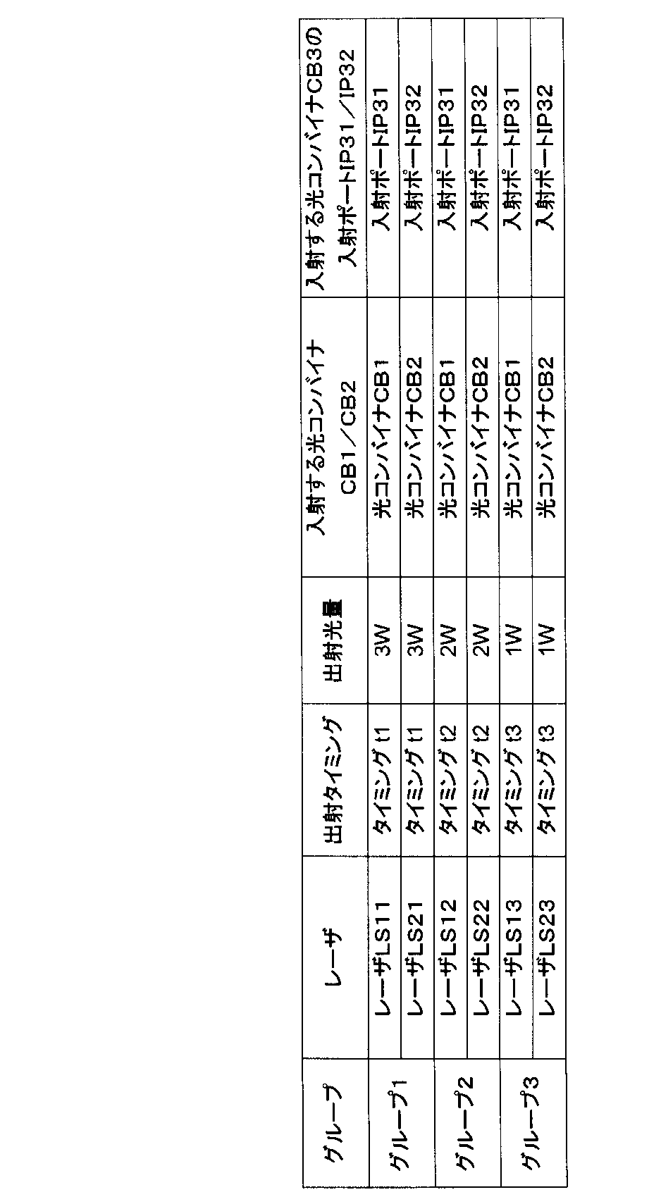
なお、「同じ出射タイミングを有する」とは、同時に出射されている期間を有するという意味を含む。つまり、出射開始のタイミングは同時刻でない場合や、出射時間が異なっていても、同時に出射されている期間を有する場合は「同じ出射タイミングを有する」という。
また、レーザの数および/または出射タイミングは本実施形態に示すものに限らない。例えば、各出射タイミングにおいてレーザ光を出射するレーザは2つに限らない。また、同じタイミングでレーザ光を出射するレーザは、同じ発光波長を有するものとも限らない。例えば、橙色のレーザや紫色のレーザが用いられてもよい。また、本実施形態では3つのサブフレームに対応して青色・緑色・赤色のレーザを順次出射しているが、サブフレームは3つに限らない。
〔動作〕
1.光源駆動部DRによってレーザLS11~LS13,LS21~LS23が順次駆動され、図8に示すように、青色領域・緑色領域・赤色領域のレーザ光が順次出射される。
1.光源駆動部DRによってレーザLS11~LS13,LS21~LS23が順次駆動され、図8に示すように、青色領域・緑色領域・赤色領域のレーザ光が順次出射される。
2.タイミングt1において、レーザLS11とレーザLS21は青色領域のレーザ光を同時に出射する。レーザLS11から出射されたレーザ光は、光ファイバFB11を導光され、入射ポートIP11から光コンバイナCB1へ入射され、光コンバイナCB1の出射ポートOP11から出射される。また、レーザLS21から出射されたレーザ光は、光ファイバFB21を導光され、入射ポートIP21から光コンバイナCB2へ入射され、光コンバイナCB2の出射ポートOP21から出射される。
3.レーザLS11から出射されたレーザ光とレーザLS21から出射されたレーザ光は、それぞれ、光コンバイナCB3の入射ポートIP31と入射ポートIP32へ入射され、出射ポートOP31からは、レーザLS11から出射されたレーザ光とレーザLS21から出射されたレーザ光の合波光が出射される。
4.レーザLS11から出射されたレーザ光とレーザLS21から出射されたレーザ光の合波光は光変換部CVによって所望の配光へ変換された後、照明光ILとして、観察体に照射される。
5.撮像部IMは、観察体によって生成された照明光ILの反射散乱光RLを検出してサブフレーム1の撮像信号を生成する。
6.タイミングt2において、レーザLS12とレーザLS22が緑色領域のレーザ光を同時に出射する。レーザLS12から出射されたレーザ光とレーザLS22から出射されたレーザ光の合波光は、上記と同様にして、光変換部CVによって所望の配光へ変換された後、照明光ILとして出射され、観察体に照射される。撮像部IMは、観察体によって生成された照明光ILの反射散乱光RLを検出してサブフレーム2の撮像信号を生成する。
7.タイミングt3において、レーザLS13とレーザLS23が赤色領域のレーザ光を同時に出射される。レーザLS13から出射されたレーザ光とレーザLS23から出射されたレーザ光の合波光は、上記と同様にして、光変換部CVによって所望の配光へ変換された後、照明光ILとして出射され、観察体に照射される。撮像部IMは、観察体によって生成された照明光ILの反射散乱光RLを検出してサブフレーム3の撮像信号を生成する。
8.画像処理部PRは、サブフレーム1~3の画像を合成して、1フレームのカラー(白色)画像を生成する。画像表示部DSは、画像処理部PRによって生成された画像を表示する。
〔効果〕
複数のレーザLS11~LS13,LS21~LS23に対して、出射タイミングを基準にグルーピングを行い、光コンバイナCB1,CB2に対して、複数のレーザLS11~LS13,LS21~LS23から出射されたレーザ光の入射光量が分散するように接続(配置)することにより、光コンバイナCB3における、入射ポートIP31と出射ポートOP31の間の光路と、入射ポートIP32と出射ポートOP31の間の光路において、時間的に光損失が分散され、時間的に発熱が分散される。すなわち、光コンバイナCB3の内部光路において、一部分のみに同時刻に発熱が集中することを防ぐことができる。これにより、光コンバイナCB3の発熱による故障を防止することができる。
複数のレーザLS11~LS13,LS21~LS23に対して、出射タイミングを基準にグルーピングを行い、光コンバイナCB1,CB2に対して、複数のレーザLS11~LS13,LS21~LS23から出射されたレーザ光の入射光量が分散するように接続(配置)することにより、光コンバイナCB3における、入射ポートIP31と出射ポートOP31の間の光路と、入射ポートIP32と出射ポートOP31の間の光路において、時間的に光損失が分散され、時間的に発熱が分散される。すなわち、光コンバイナCB3の内部光路において、一部分のみに同時刻に発熱が集中することを防ぐことができる。これにより、光コンバイナCB3の発熱による故障を防止することができる。
<第3実施形態>
[構成]
第3実施形態は、第2実施形態と同様に、内視鏡である。図9は、第3実施形態における内視鏡の構成模式図である。第3実施形態の内視鏡は、第2実施形態の内視鏡との比較において、照明装置の2次合波部である光コンバイナCB3が光カプラCPに置き換えられ、これに伴って、光ファイバFB31と光変換部CVが2本の光ファイバFB41,FB42と2つの光変換部CV1,CV2に置き換えられた構成となっている。また撮像部IMは、カラーイメージャで構成されている。
[構成]
第3実施形態は、第2実施形態と同様に、内視鏡である。図9は、第3実施形態における内視鏡の構成模式図である。第3実施形態の内視鏡は、第2実施形態の内視鏡との比較において、照明装置の2次合波部である光コンバイナCB3が光カプラCPに置き換えられ、これに伴って、光ファイバFB31と光変換部CVが2本の光ファイバFB41,FB42と2つの光変換部CV1,CV2に置き換えられた構成となっている。また撮像部IMは、カラーイメージャで構成されている。
〔光カプラCP(2次合波部、光合波分波部)〕
本実施形態における光カプラCPの一例を図10に示す。光カプラCPは、2つの入射ポートIP41,IP42と、2つの出射ポートOP41,OP42を有している。光カプラCPは、入射ポートIP41に入射した光と入射ポートIP42に入射した光を合波し、その合波光を出射ポートOP41と出射ポートOP42へ分波する機能を有している。光カプラCPは、入射ポートIP41に入射した光を、理想的には1:1に比率で出射ポートOP41と出射ポートOP42へ分岐するとともに、入射ポートIP42に入射した光を、理想的には1:1に比率で出射ポートOP41と出射ポートOP42へ分岐する。
本実施形態における光カプラCPの一例を図10に示す。光カプラCPは、2つの入射ポートIP41,IP42と、2つの出射ポートOP41,OP42を有している。光カプラCPは、入射ポートIP41に入射した光と入射ポートIP42に入射した光を合波し、その合波光を出射ポートOP41と出射ポートOP42へ分波する機能を有している。光カプラCPは、入射ポートIP41に入射した光を、理想的には1:1に比率で出射ポートOP41と出射ポートOP42へ分岐するとともに、入射ポートIP42に入射した光を、理想的には1:1に比率で出射ポートOP41と出射ポートOP42へ分岐する。
再び図9を参照して説明する。
入射ポートIP41には、光ファイバFB14が接続され、第1の1次合波光が入射される。
入射ポートIP42には、光ファイバFB24が接続され、第2の1次合波光が入射される。
出射ポートOP41からは、第1の1次合波光と第2の1次合波光が合波された第1の2次合波光が出射される。
入射ポートIP42からは、第1の1次合波光と第2の1次合波光が合波された第2の2次合波光が出射される。
入射ポートIP41には、光ファイバFB14が接続され、第1の1次合波光が入射される。
入射ポートIP42には、光ファイバFB24が接続され、第2の1次合波光が入射される。
出射ポートOP41からは、第1の1次合波光と第2の1次合波光が合波された第1の2次合波光が出射される。
入射ポートIP42からは、第1の1次合波光と第2の1次合波光が合波された第2の2次合波光が出射される。
〔光ファイバFB41,FB42〕
光ファイバFB41の入射端は、光カプラCPの出射ポートOP41に接続され、光ファイバFB41の出射端は、光変換部CV1に接続されている。光ファイバFB42の入射端は、光カプラCPの出射ポートOP42に接続され、光ファイバFB42の出射端は、光変換部CV2に接続されている。光ファイバFB41,FB42はいずれも、第2実施形態の光ファイバFB31すなわち第1実施形態の光ファイバFB31と実質的に同じ特性を有している。
光ファイバFB41の入射端は、光カプラCPの出射ポートOP41に接続され、光ファイバFB41の出射端は、光変換部CV1に接続されている。光ファイバFB42の入射端は、光カプラCPの出射ポートOP42に接続され、光ファイバFB42の出射端は、光変換部CV2に接続されている。光ファイバFB41,FB42はいずれも、第2実施形態の光ファイバFB31すなわち第1実施形態の光ファイバFB31と実質的に同じ特性を有している。
〔光変換部CV1,CV2〕
光変換部CV1,CV2は共に、第2実施形態の光変換部CVと同様に、内視鏡の挿入部ISの先端部に配置されている。光変換部CV1,CV2はいずれも、第2実施形態の光変換部CVすなわち第1実施形態の光変換部CVと実質的に同一の特性を有している。光変換部CV1は、光ファイバFB41から入射される2次合波光を所望の配光へ変換して照明光IL1として出射する。光変換部CV2は、光ファイバFB42から入射される2次合波光を所望の配光へ変換して照明光IL2として出射する。
光変換部CV1,CV2は共に、第2実施形態の光変換部CVと同様に、内視鏡の挿入部ISの先端部に配置されている。光変換部CV1,CV2はいずれも、第2実施形態の光変換部CVすなわち第1実施形態の光変換部CVと実質的に同一の特性を有している。光変換部CV1は、光ファイバFB41から入射される2次合波光を所望の配光へ変換して照明光IL1として出射する。光変換部CV2は、光ファイバFB42から入射される2次合波光を所望の配光へ変換して照明光IL2として出射する。
第3実施形態は、第2実施形態に対して、複数のレーザLS11~LS13,LS21~LS23に対するグルーピングの基準と分配方法が異なる。また、レーザLS11~LS13,LS21~LS23は、第1の実施形態と同様に、同時にレーザ光を出射する。また、本実施形態においては、レーザLS11~LS13,LS21~LS23は同じ1Wの出射光量を有している。
〔第3実施形態における課題〕
光カプラCPの分岐比は、略1:1となるように設計されていても、製造誤差によりその分岐比は設計値からずれることがある。例えば、光カプラCPの入射ポートIP41から入射された場合には、光カプラCPの出射ポートOP41と出射ポートOP42に対する分岐比は1.1:0.9のように分岐比に偏りができ、一方、光カプラCPの入射ポートIP42から入射された場合には、光カプラCPの出射ポートOP41と出射ポートOP42に対する分岐比は0.9:1.1のように、入射ポートIP41から入射された場合とは逆の分岐比の偏りができてしまう。
光カプラCPの分岐比は、略1:1となるように設計されていても、製造誤差によりその分岐比は設計値からずれることがある。例えば、光カプラCPの入射ポートIP41から入射された場合には、光カプラCPの出射ポートOP41と出射ポートOP42に対する分岐比は1.1:0.9のように分岐比に偏りができ、一方、光カプラCPの入射ポートIP42から入射された場合には、光カプラCPの出射ポートOP41と出射ポートOP42に対する分岐比は0.9:1.1のように、入射ポートIP41から入射された場合とは逆の分岐比の偏りができてしまう。
このとき、入射ポートIP41に入射される第1の1次合波光と入射ポートIP42に入射される第2の1次合波光との間に色差があると、出射ポートOP41から出射される第1の2次合波光と出射ポートOP42から出射される第2の2次合波光との間の色差はより大きくなる。それに伴い、光変換部CV1から出射される照明光IL1と光変換部CV2から出射される照明光IL2との間の色差も大きくなる。これにより、照明光IL1と照明光IL2の重ね合わせである総合の照明光は、配光によって色が異なってしまい、つまり照明光に色むらが生じてしまい、これが観察に悪影響を及ぼす虞がある。
〔レーザLS11~LS13,LS21~LS23と光コンバイナCB1,CB2の接続(配置)構成〕
本実施形態では、レーザLS11~LS13,LS21~LS23は、発光波長を基準としてグルーピングされており、所定の波長範囲に含まれる発光波長を有するレーザは同じグループにグルーピングされている。本実施形態においては、所定の波長範囲は、第1実施形態において定義された青色領域・緑色領域・赤色領域の各色領域である。すなわち、同じ色領域に含まれる発光波長を有する狭帯域光源は同じグループにグルーピングされている。また、本実施形態においては、レーザLS11とレーザLS21は同じ445nmの発光波長を有し、レーザLS12とレーザLS22は同じ525nmの発光波長を有し、レーザLS13とレーザLS23は同じ635nmの発光波長を有している。同じ発光波長を有するレーザLSは同じグループにグルーピングされている。ここで、「同じ発光波長」とは、設計上同じであることを示しており、製造ばらつき等により発光波長が数nm程度違うレーザも同じ発光波長を有しているとみなす。
本実施形態では、レーザLS11~LS13,LS21~LS23は、発光波長を基準としてグルーピングされており、所定の波長範囲に含まれる発光波長を有するレーザは同じグループにグルーピングされている。本実施形態においては、所定の波長範囲は、第1実施形態において定義された青色領域・緑色領域・赤色領域の各色領域である。すなわち、同じ色領域に含まれる発光波長を有する狭帯域光源は同じグループにグルーピングされている。また、本実施形態においては、レーザLS11とレーザLS21は同じ445nmの発光波長を有し、レーザLS12とレーザLS22は同じ525nmの発光波長を有し、レーザLS13とレーザLS23は同じ635nmの発光波長を有している。同じ発光波長を有するレーザLSは同じグループにグルーピングされている。ここで、「同じ発光波長」とは、設計上同じであることを示しており、製造ばらつき等により発光波長が数nm程度違うレーザも同じ発光波長を有しているとみなす。
本実施形態においては、レーザLS11~LS13,LS21~LS23は次のようにグルーピングされている。
・グループ1:レーザLS11,LS21
・グループ2:レーザLS12,LS22
・グループ3:レーザLS13,LS23
同じグループに属するレーザLS11,LS21とLS12,LS22とLS13,LS23は、それぞれ、第1の1次合波光と第2の1次合波光の色差が所定値以下となるように、光コンバイナCB1,CB2に対して分配されている。言い換えれば、同じグループに属するレーザLS11,LS21とLS12,LS22とLS13,LS23は、照明光IL1と照明光IL2の色差が所定値以下となるように光コンバイナCB1,CB2に対して分配される。また、本実施形態においては、同じグループに属するレーザLS11,LS21とLS12,LS22とLS13,LS23は、光コンバイナCB1,CB2に対して同じ数ずつ分配されている。
・グループ1:レーザLS11,LS21
・グループ2:レーザLS12,LS22
・グループ3:レーザLS13,LS23
同じグループに属するレーザLS11,LS21とLS12,LS22とLS13,LS23は、それぞれ、第1の1次合波光と第2の1次合波光の色差が所定値以下となるように、光コンバイナCB1,CB2に対して分配されている。言い換えれば、同じグループに属するレーザLS11,LS21とLS12,LS22とLS13,LS23は、照明光IL1と照明光IL2の色差が所定値以下となるように光コンバイナCB1,CB2に対して分配される。また、本実施形態においては、同じグループに属するレーザLS11,LS21とLS12,LS22とLS13,LS23は、光コンバイナCB1,CB2に対して同じ数ずつ分配されている。
本実施形態においては、レーザLS11~LS13,LS21~LS23は、表4に示されるように、光コンバイナCB1,CB2に対して分配される。このとき、光カプラCPに入射される第1の1次合波光と第2の1次合波光の色差が最も小さくなる(この場合、略等しくなる)。また、本実施形態においては、光変換部CV1と光変換部CV2は略同一の特性であるので、照明光IL1と照明光IL2の色差が最も小さくなる(この場合、略等しくなる)。

ここで、本実施形態における色差とは、「光の色の差」を示す。色差の評価値としては、例えば、中心波長の差を用いることができる。中心波長λcは、レーザの出射光量をPi、発光波長をλiとしたとき、次式(1)で定義される。

また、色差の別の評価値としては、例えば、図11に示されるCIE 1976 L*u*v*表色系の色空間座標の距離が用いられてもよい。また、照明光の色の差ではなく、代表的な観察体における反射光の色の差を基準にしてもよい。これは「観察体に対する色再現性の差」を示す。上記中心波長の差としては例えば50nm以下であればよい。また、上記色空間座標の距離としては例えば次式(2)が0.3以下であればよい。そうであれば、後述するように、光変換部CV1から出射される照明光IL1と光変換部CV2から出射される照明光IL2において色差が小さくなり、色が略均一な良好な照明特性を有する内視鏡を提供できる。

なお、第1の1次合波光と第2の1次合波光の色差が最も小さくなるように接続されるのが最も好ましいが、実施形態はそれに限らない。例えば、同じ色領域に含まれるレーザLS11~LS13,LS21~LS23が光コンバイナCB1,CB2に対して接続されていればよい。
なお、レーザの数および/または発光波長は本実施形態に示すものに限らない。例えば、すべてのレーザが異なる発光波長を有していてもよい。例えば、橙色のレーザや紫色のレーザが用いられてもよい。また、光源は、レーザに限らず、狭帯域光源であればよく、LED等の狭帯域光源で構成されてもよい。
〔動作〕
1.光源駆動部DRによってレーザLS11~LS13,LS21~LS23が駆動され、レーザ光が同時に出射される。
1.光源駆動部DRによってレーザLS11~LS13,LS21~LS23が駆動され、レーザ光が同時に出射される。
2.レーザLS11~LS13から出射されたレーザ光は光ファイバFB11~FB13を導光された後、入射ポートIP11~IP13から光コンバイナCB1へ入射される。光コンバイナCB1の出射ポートOP11から、レーザLS11~LS13から出射されたレーザ光の合波光である第1の1次合波光が出射される。第1の1次合波光は白色光である。
3.レーザLS21~LS23から出射されたレーザ光は光ファイバFB21~FB23を導光された後、入射ポートIP21~IP23から光コンバイナCB2へ入射される。光コンバイナCB2の出射ポートOP21から、レーザLS21~LS23から出射されたレーザ光の合波光である第2の1次合波光が出射される。第2の1次合波光は白色光である。
4.第1の1次合波光は光ファイバFB21を導光された後、入射ポートIP41から光カプラCPへ入射される。
5.第2の1次合波光は光ファイバFB22を導光された後、入射ポートIP42から光カプラCPへ入射される。
6.光カプラCPの出射ポートOP41と出射ポートOP42からは、第1の1次合波光と第2の1次合波光の合波光である2次合波光が出射される。2次合波光は白色光である。
7.2次合波光は光ファイバFB31を導光された後、光変換部CVへ入射される。
8.2次合波光は光変換部CV1,IL2によって所望の配光へ変換された後、照明光IL1,IL2として出射され、観察体に照射される。
9.撮像部IMは、観察体によって生成された照明光IL1,IL2の反射散乱光RLを検出して撮像信号を生成する。
10.画像処理部PRは、撮像部IMから供給される撮像信号を処理して画像を生成する。画像表示部DSは、画像処理部PRによって生成された画像を表示する。
〔効果〕
複数のレーザLS11~LS13,LS21~LS23に対して、発光波長を基準にグルーピングを行い、光コンバイナCB1,CB2に対して、第1の1次合波光と第2の1次合波光の色差が所定値以下となるように接続(配置)することにより、照明光IL1と照明光IL2の色差が所定値以下に低く抑えられる。これにより、照明光の色むらの発生が低減され、良好な観察に貢献する。
複数のレーザLS11~LS13,LS21~LS23に対して、発光波長を基準にグルーピングを行い、光コンバイナCB1,CB2に対して、第1の1次合波光と第2の1次合波光の色差が所定値以下となるように接続(配置)することにより、照明光IL1と照明光IL2の色差が所定値以下に低く抑えられる。これにより、照明光の色むらの発生が低減され、良好な観察に貢献する。
<各実施形態に適用可能な変形>
狭帯域光源の数は、ここに説明した実施形態におけるレーザの数に限定されることなく、適切に変更されてよい。
狭帯域光源の数は、ここに説明した実施形態におけるレーザの数に限定されることなく、適切に変更されてよい。
例えば、照明装置は、少なくとも4つの狭帯域光源と、これら少なくとも4つの狭帯域光源の少なくとも2つから出射された狭帯域光をそれぞれ合波する複数の1次合波部と、これらの1次合波部によって合波された1次合波光を合波する1つの2次合波部を有している構成であってよい。一例としては、照明装置は、第1実施形態の照明装置において、レーザLS13とレーザLS23が省かれた構成であってもよい。
さらには、照明装置は、少なくとも3つの狭帯域光源と、これら少なくとも3つの狭帯域光源の少なくとも2つから出射された狭帯域光を合波する少なくとも1つの1次合波部と、この1次合波部によって合波された1次合波光と、上記の少なくとも2つの狭帯域光源を除いた狭帯域光源から出射された狭帯域光とを合波する1つの2次合波部を有している構成であってもよい。例えば、照明装置は、第1実施形態の照明装置において、レーザLS13とレーザLS22とレーザLS23が省かれ、さらに光コンバイナCB2が省かれた構成であってもよい。
このような各構成も、実施形態で説明された利点と同じ利点を有し得る。
Claims (25)
- 少なくとも4つの狭帯域光源と、
前記狭帯域光源の少なくとも2つから出射された狭帯域光をそれぞれ合波する複数の1次合波部と、
前記複数の1次合波部によって合波された1次合波光を合波する2次合波部を有し、
前記2次合波部によって合波された2次合波光を照明光として出射する照明装置において、
前記複数の狭帯域光源は、前記狭帯域光の照明特性をグルーピングの基準として、前記照明特性において所定の条件を満たす狭帯域光源が同じグループに含まれるように、複数のグループにグルーピングされており、
同じグループに属する複数の狭帯域光源の各々は、前記同じグループに属する複数の狭帯域光源が前記複数の1次合波部に分配されるように前記複数の1次合波部のいずれか1つに接続されていることを特徴とする照明装置。 - 前記1次合波部の各々は、前記少なくとも4つの狭帯域光源の少なくとも2つから出射された狭帯域光が入射される少なくとも2つの1次合波部入射ポートと、前記1次合波光を出射する少なくとも1つの1次合波部出射ポートとを有し、
前記2次合波部は、前記複数の1次合波部によって合波された前記1次合波光が入射される複数の2次合波部入射ポートと、前記2次合波光を出射する少なくとも1つの2次合波部出射ポートとを有することを特徴とする請求項1記載の照明装置。 - 少なくとも3つの狭帯域光源と、
前記狭帯域光源の少なくとも2つから出射された狭帯域光を合波する少なくとも1つの1次合波部と、
前記1次合波部によって合波された1次合波光と、前記少なくとも2つの狭帯域光源を除いた狭帯域光源から出射された狭帯域光とを合波する2次合波部を有し、
前記2次合波部によって合波された2次合波光を照明光として出射する照明装置において、
前記複数の狭帯域光源は、前記狭帯域光の照明特性をグルーピングの基準として、前記照明特性において所定の条件を満たす狭帯域光源が同じグループに含まれるように、少なくとも1つのグループにグルーピングされており、
同じグループに属する複数の狭帯域光源の各々は、前記同じグループに属する複数の狭帯域光源が前記少なくとも1つの1次合波部と前記2次合波部に対して前記照明特性が分配されるように、前記少なくとも1つの1次合波部と前記2次合波部のいずれか1つに接続されていることを特徴とする照明装置。 - 前記1次合波部の各々は、前記少なくとも3つの狭帯域光源の少なくとも2つから出射された狭帯域光が入射される複数の1次合波部入射ポートと、前記1次合波光を出射する少なくとも1つの1次合波部出射ポートとを有し、
前記2次合波部は、前記1次合波部によって合波された前記1次合波光と、前記少なくとも2つの狭帯域光源を除いた狭帯域光源から出射された狭帯域光とが入射される複数の2次合波部入射ポートと、前記2次合波光を出射する少なくとも1つの2次合波部出射ポートとを有することを特徴とする請求項2に記載の照明装置。 - 前記照明特性は出射光量と発光波長と出射タイミングの少なくとも1つであり、前記複数の狭帯域光源のうち、出射光量と発光波長と出射タイミングの少なくとも1つが所定の範囲内に含まれる狭帯域光源同士は同じグループとなるようにグルーピングされていることを特徴とする請求項1ないし4のいずれかひとつに記載の照明装置。
- グルーピングの基準は前記狭帯域光源の出射光量であり、所定の光量範囲に含まれる出射光量を有する狭帯域光源は同じグループにグルーピングされていることを特徴とする請求項5に記載の照明装置。
- グルーピングの基準は前記狭帯域光源の出射タイミングであり、前記複数の狭帯域光源から狭帯域光が順次異なる出射タイミングで出射される場合、同じ出射タイミングを有する狭帯域光源は同じグループにグルーピングされていることを特徴とする請求項5に記載の照明装置。
- グルーピングの基準は前記狭帯域光源の発光波長であり、所定の波長範囲に含まれる発光波長を有する狭帯域光源は同じグループにグルーピングされていることを特徴とする請求項5に記載の照明装置。
- 青色領域・緑色領域・赤色領域の3つの色領域に対して、同じ色領域に含まれる発光波長を有する狭帯域光源は同じグループにグルーピングされていることを特徴とする請求項8に記載の照明装置。
- 前記複数の狭帯域光源のうち、略等しい照明特性を有する狭帯域光源は同じグループにグルーピングされていることを特徴とする請求項5に記載の照明装置。
- 同じグループに属する複数の狭帯域光源は、前記複数の1次合波部から出射される1次合波光の光量差が所定値以下となるように、前記複数の1次合波部に対して分配されていることを特徴とする請求項6に記載の照明装置。
- 同じグループに属する複数の狭帯域光源は、前記複数の1次合波光の色差が所定値以下となるように、前記複数の1次合波部に対して分配されていることを特徴とする請求項8または9に記載の照明装置。
- 同じグループに属する複数の狭帯域光源は、前記同じグループにおいて前記複数の1次合波部に対して分配される前記狭帯域光源の数の差が1以下となるように、前記複数の1次合波部に対して分配されていることを特徴とする請求項6ないし9のいずれかひとつに記載の照明装置。
- 前記複数の狭帯域光源は、少なくとも2つの同じ色領域の発光波長を有する狭帯域光源を含んでいることを特徴とする請求項1ないし4のいずれかひとつに記載の照明装置。
- 前記2次合波部出射ポートが1つのみの場合は、グルーピングの基準は、前記狭帯域光源の発光波長よりも、前記狭帯域光源の出射光量または前記狭帯域光源の出射タイミングが優先されて選択されることを特徴とする請求項2または4に記載の照明装置。
- 前記2次合波部出射ポートが複数の場合は、グルーピングの基準は、前記狭帯域光源の出射光量または前記狭帯域光源の出射タイミングよりも、前記狭帯域光源の発光波長が優先されて選択されることを特徴とする請求項2または4に記載の照明装置。
- 前記複数の狭帯域光源は、出射光量の大きい順に順序づけられており、前記複数の狭帯域光源は、出射光量の大きいものから順番に所定の個数ずつ区切られてグルーピングされており、余った狭帯域光源は、隣り合う狭帯域光源が含まれるグループにグルーピングされていることを特徴とする請求項6に記載の照明装置。
- 前記複数の狭帯域光源は、出射光量の大きい順に順序づけられており、前記複数の狭帯域光源のうち、同じ出射光量を有する狭帯域光源は同じグループにグルーピングされ、他の狭帯域光源と同じ出射光量を有さない狭帯域光源は、隣り合う狭帯域光源のうち、出射光量の近い方の狭帯域光源と同じグループにグルーピングされ、出射光量の近い隣り合う狭帯域光源がすでにグルーピングされている場合は、そのグループに含められていることを特徴とする請求項6に記載の照明装置。
- 前記複数の狭帯域光源は、出射光量の大きい順に順序づけられており、前記複数の狭帯域光源は、最も出射光量の大きい1番目の狭帯域光源の出射光量と、最も出射光量の小さい最終番目の狭帯域光源の出射光量の間の光量範囲を略等間隔に区切ることによってグルーピングされていることを特徴とする請求項6に記載の照明装置。
- 前記複数の狭帯域光源は、出射光量の大きい順に順序づけられており、最も出射光量の大きい1番目の狭帯域光源の出射光量が、それ以外の狭帯域光源の出射光量の総和よりも大きい場合は、1番目の狭帯域光源は、グルーピングされずに、前記2次合波部に直接接続されていることを特徴とする請求項2に記載の照明装置。
- 前記複数の狭帯域光源は、グループに含まれる狭帯域光源の平均出射光量が大きいグループから先に分配されていることを特徴とする請求項6に記載の照明装置。
- グループに含まれる狭帯域光源は、出射光量の大きい狭帯域光源から順に前記1次合波部の数ずつ前記複数の1次合波部に等しく分配され、余った狭帯域光源は、最初の分配において出射光量の小さい狭帯域光源が分配された1次合波部から優先して分配されていることを特徴とする請求項1に記載の照明装置。
- 第一のグループの狭帯域光源が他の1または複数の1次合波部よりも多く分配された1または複数の1次合波部に対しては、第二のグループの狭帯域光源は、前記他の1次合波部よりも多く分配されていないことを特徴とする請求項1に記載の照明装置。
- 第一のグループの狭帯域光源が他の1または複数の1次合波部よりも入射光量が大きくなるように分配された1次合波部に対しては、第二のグループの狭帯域光源は、前記他の1次合波部よりも入射光量が大きくなるように分配されていないことを特徴とする請求項1に記載の照明装置。
- 請求項1ないし24のいずれかひとつに記載の照明装置を有する内視鏡。
Priority Applications (3)
| Application Number | Priority Date | Filing Date | Title |
|---|---|---|---|
| JP2018510218A JPWO2017175391A1 (ja) | 2016-04-08 | 2016-04-08 | 照明装置およびこれを備えた内視鏡 |
| PCT/JP2016/061580 WO2017175391A1 (ja) | 2016-04-08 | 2016-04-08 | 照明装置およびこれを備えた内視鏡 |
| US16/152,471 US20190041579A1 (en) | 2016-04-08 | 2018-10-05 | Illumination device and endoscope including the same |
Applications Claiming Priority (1)
| Application Number | Priority Date | Filing Date | Title |
|---|---|---|---|
| PCT/JP2016/061580 WO2017175391A1 (ja) | 2016-04-08 | 2016-04-08 | 照明装置およびこれを備えた内視鏡 |
Related Child Applications (1)
| Application Number | Title | Priority Date | Filing Date |
|---|---|---|---|
| US16/152,471 Continuation US20190041579A1 (en) | 2016-04-08 | 2018-10-05 | Illumination device and endoscope including the same |
Publications (1)
| Publication Number | Publication Date |
|---|---|
| WO2017175391A1 true WO2017175391A1 (ja) | 2017-10-12 |
Family
ID=60000941
Family Applications (1)
| Application Number | Title | Priority Date | Filing Date |
|---|---|---|---|
| PCT/JP2016/061580 Ceased WO2017175391A1 (ja) | 2016-04-08 | 2016-04-08 | 照明装置およびこれを備えた内視鏡 |
Country Status (3)
| Country | Link |
|---|---|
| US (1) | US20190041579A1 (ja) |
| JP (1) | JPWO2017175391A1 (ja) |
| WO (1) | WO2017175391A1 (ja) |
Cited By (2)
| Publication number | Priority date | Publication date | Assignee | Title |
|---|---|---|---|---|
| WO2020196521A1 (ja) * | 2019-03-27 | 2020-10-01 | 古河電気工業株式会社 | レーザ装置 |
| JP2022122788A (ja) * | 2021-02-10 | 2022-08-23 | オリンパス株式会社 | 内視鏡、内視鏡システム、及び内視鏡の製造方法 |
Families Citing this family (2)
| Publication number | Priority date | Publication date | Assignee | Title |
|---|---|---|---|---|
| CN116744836A (zh) * | 2021-02-10 | 2023-09-12 | 奥林巴斯医疗株式会社 | 内窥镜、内窥镜系统及内窥镜的制造方法 |
| CN115189774B (zh) * | 2022-06-29 | 2023-05-23 | 武汉光迅科技股份有限公司 | 一种可编组光模块及使用方法 |
Citations (5)
| Publication number | Priority date | Publication date | Assignee | Title |
|---|---|---|---|---|
| JPH11119733A (ja) * | 1997-10-16 | 1999-04-30 | Toyoda Gosei Co Ltd | 発光ダイオードの電源装置 |
| JP2005189385A (ja) * | 2003-12-25 | 2005-07-14 | Sony Corp | 分岐型光導波路、光源モジュール、並びに光情報処理装置 |
| JP2006004839A (ja) * | 2004-06-18 | 2006-01-05 | Sanyo Electric Co Ltd | Led照明装置 |
| JP2007041342A (ja) * | 2005-08-04 | 2007-02-15 | Fujifilm Corp | 合波光源 |
| JP2012194448A (ja) * | 2011-03-17 | 2012-10-11 | Fujifilm Corp | 光コネクタおよび内視鏡システム |
Family Cites Families (18)
| Publication number | Priority date | Publication date | Assignee | Title |
|---|---|---|---|---|
| US3825336A (en) * | 1973-01-04 | 1974-07-23 | Polaroid Corp | Variable color photographic lighting source |
| CA1123528A (en) * | 1977-07-12 | 1982-05-11 | Elmer H. Hara | Frequency division multiplexing system for optical transmission of broadband signals |
| FR2674711B1 (fr) * | 1991-03-28 | 1993-08-06 | Guignard Philippe | Dispositif rapidement reconfigurable de multiplexage en longueur d'onde. |
| US6212310B1 (en) * | 1996-10-22 | 2001-04-03 | Sdl, Inc. | High power fiber gain media system achieved through power scaling via multiplexing |
| US6373568B1 (en) * | 1999-08-06 | 2002-04-16 | Cambridge Research & Instrumentation, Inc. | Spectral imaging system |
| US6741351B2 (en) * | 2001-06-07 | 2004-05-25 | Koninklijke Philips Electronics N.V. | LED luminaire with light sensor configurations for optical feedback |
| JP2004361472A (ja) * | 2003-06-02 | 2004-12-24 | Fuji Photo Film Co Ltd | レーザ装置 |
| CN101031837B (zh) * | 2004-07-23 | 2011-06-15 | 通用电气医疗集团尼亚加拉有限公司 | 用于荧光共焦显微镜检查的方法和设备 |
| US20080310181A1 (en) * | 2007-06-15 | 2008-12-18 | Microalign Technologies, Inc. | Brightness with reduced optical losses |
| US7791009B2 (en) * | 2007-11-27 | 2010-09-07 | University Of Washington | Eliminating illumination crosstalk while using multiple imaging devices with plural scanning devices, each coupled to an optical fiber |
| JP2009153712A (ja) * | 2007-12-26 | 2009-07-16 | Olympus Corp | 光源装置およびそれを備えた内視鏡装置 |
| US8757812B2 (en) * | 2008-05-19 | 2014-06-24 | University of Washington UW TechTransfer—Invention Licensing | Scanning laser projection display devices and methods for projecting one or more images onto a surface with a light-scanning optical fiber |
| EP3610778B1 (en) * | 2008-11-18 | 2023-07-05 | Stryker Corporation | Endoscopic led light source having a feedback control system |
| US8855447B2 (en) * | 2010-08-12 | 2014-10-07 | Octrolix Bv | Scanning laser projector |
| EP2882994B1 (en) * | 2012-08-07 | 2020-01-08 | University of South Alabama | Spectral illumination device and method |
| JP6103959B2 (ja) * | 2013-01-29 | 2017-03-29 | オリンパス株式会社 | 光源装置及び被検体観察装置並びに光源制御方法 |
| US9777913B2 (en) * | 2013-03-15 | 2017-10-03 | DePuy Synthes Products, Inc. | Controlling the integral light energy of a laser pulse |
| JP6460631B2 (ja) * | 2014-02-19 | 2019-01-30 | オリンパス株式会社 | 撮像装置、内視鏡装置及び顕微鏡装置 |
-
2016
- 2016-04-08 WO PCT/JP2016/061580 patent/WO2017175391A1/ja not_active Ceased
- 2016-04-08 JP JP2018510218A patent/JPWO2017175391A1/ja active Pending
-
2018
- 2018-10-05 US US16/152,471 patent/US20190041579A1/en not_active Abandoned
Patent Citations (5)
| Publication number | Priority date | Publication date | Assignee | Title |
|---|---|---|---|---|
| JPH11119733A (ja) * | 1997-10-16 | 1999-04-30 | Toyoda Gosei Co Ltd | 発光ダイオードの電源装置 |
| JP2005189385A (ja) * | 2003-12-25 | 2005-07-14 | Sony Corp | 分岐型光導波路、光源モジュール、並びに光情報処理装置 |
| JP2006004839A (ja) * | 2004-06-18 | 2006-01-05 | Sanyo Electric Co Ltd | Led照明装置 |
| JP2007041342A (ja) * | 2005-08-04 | 2007-02-15 | Fujifilm Corp | 合波光源 |
| JP2012194448A (ja) * | 2011-03-17 | 2012-10-11 | Fujifilm Corp | 光コネクタおよび内視鏡システム |
Cited By (5)
| Publication number | Priority date | Publication date | Assignee | Title |
|---|---|---|---|---|
| WO2020196521A1 (ja) * | 2019-03-27 | 2020-10-01 | 古河電気工業株式会社 | レーザ装置 |
| JP2020160310A (ja) * | 2019-03-27 | 2020-10-01 | 古河電気工業株式会社 | レーザ装置 |
| JP7203658B2 (ja) | 2019-03-27 | 2023-01-13 | 古河電気工業株式会社 | レーザ装置 |
| US12184038B2 (en) | 2019-03-27 | 2024-12-31 | Furukawa Electric Co., Ltd. | Laser apparatus |
| JP2022122788A (ja) * | 2021-02-10 | 2022-08-23 | オリンパス株式会社 | 内視鏡、内視鏡システム、及び内視鏡の製造方法 |
Also Published As
| Publication number | Publication date |
|---|---|
| US20190041579A1 (en) | 2019-02-07 |
| JPWO2017175391A1 (ja) | 2019-03-28 |
Similar Documents
| Publication | Publication Date | Title |
|---|---|---|
| US7780326B2 (en) | Optical fiber lighting apparatus | |
| CN104981199B (zh) | 光源装置 | |
| US7239449B2 (en) | Illumination module for color display | |
| WO2015182025A1 (en) | Illumination apparatus, method and medical imaging system | |
| US20120307512A1 (en) | Multi-Wavelength Multi-Lamp Radiation Sources and Systems and Apparatuses Incorporating Same | |
| US20190041579A1 (en) | Illumination device and endoscope including the same | |
| JP6682631B2 (ja) | 複数の狭帯域光源を備えた照明装置および同照明装置を備えた内視鏡 | |
| US10548466B2 (en) | Light source module and endoscope light source system | |
| CN106231988A (zh) | 内窥镜装置 | |
| CN105223761A (zh) | 投影装置及照明系统 | |
| US20220221649A1 (en) | Optical Multiplexing Circuit and Light Source | |
| US12072528B2 (en) | Optical multiplexing circuit | |
| US8837043B2 (en) | Light source arrangement for an illumination device of a medical-optical observation apparatus | |
| US8545029B2 (en) | Hybrid high pressure mercury arc lamp-laser light production system | |
| JP2016173484A (ja) | 投影レンズおよびプロジェクター | |
| JP2007529035A (ja) | 単色光源を有するフレーム順次方式のカラー投影型ディスプレイシステム用の光エンジン、システム及び駆動方法 | |
| JP2008546144A (ja) | 均一放射照度および光強度のための光パイプ積分器 | |
| JP6115967B2 (ja) | 内視鏡システム | |
| WO2022239436A1 (ja) | 照明システム | |
| US12197006B2 (en) | Optical multiplexing circuit and light source | |
| JP5675911B2 (ja) | 光ファイバ照明装置 | |
| US10440295B2 (en) | Image forming apparatus | |
| US9810891B2 (en) | Dual light source enhanced integration system | |
| JP2014085432A (ja) | レーザ光出射装置 | |
| WO2015146535A1 (ja) | 光源装置及び画像投影装置 |
Legal Events
| Date | Code | Title | Description |
|---|---|---|---|
| ENP | Entry into the national phase |
Ref document number: 2018510218 Country of ref document: JP Kind code of ref document: A |
|
| NENP | Non-entry into the national phase |
Ref country code: DE |
|
| 121 | Ep: the epo has been informed by wipo that ep was designated in this application |
Ref document number: 16897947 Country of ref document: EP Kind code of ref document: A1 |
|
| 122 | Ep: pct application non-entry in european phase |
Ref document number: 16897947 Country of ref document: EP Kind code of ref document: A1 |