WO2017170788A1 - Heavy-duty pneumatic tire - Google Patents
Heavy-duty pneumatic tire Download PDFInfo
- Publication number
- WO2017170788A1 WO2017170788A1 PCT/JP2017/013095 JP2017013095W WO2017170788A1 WO 2017170788 A1 WO2017170788 A1 WO 2017170788A1 JP 2017013095 W JP2017013095 W JP 2017013095W WO 2017170788 A1 WO2017170788 A1 WO 2017170788A1
- Authority
- WO
- WIPO (PCT)
- Prior art keywords
- groove
- tire
- grooves
- center
- narrow
- Prior art date
Links
Images

Classifications
-
- B—PERFORMING OPERATIONS; TRANSPORTING
- B60—VEHICLES IN GENERAL
- B60C—VEHICLE TYRES; TYRE INFLATION; TYRE CHANGING; CONNECTING VALVES TO INFLATABLE ELASTIC BODIES IN GENERAL; DEVICES OR ARRANGEMENTS RELATED TO TYRES
- B60C11/00—Tyre tread bands; Tread patterns; Anti-skid inserts
- B60C11/03—Tread patterns
- B60C11/0306—Patterns comprising block rows or discontinuous ribs
-
- B—PERFORMING OPERATIONS; TRANSPORTING
- B60—VEHICLES IN GENERAL
- B60C—VEHICLE TYRES; TYRE INFLATION; TYRE CHANGING; CONNECTING VALVES TO INFLATABLE ELASTIC BODIES IN GENERAL; DEVICES OR ARRANGEMENTS RELATED TO TYRES
- B60C11/00—Tyre tread bands; Tread patterns; Anti-skid inserts
- B60C11/03—Tread patterns
- B60C11/13—Tread patterns characterised by the groove cross-section, e.g. for buttressing or preventing stone-trapping
-
- B—PERFORMING OPERATIONS; TRANSPORTING
- B60—VEHICLES IN GENERAL
- B60C—VEHICLE TYRES; TYRE INFLATION; TYRE CHANGING; CONNECTING VALVES TO INFLATABLE ELASTIC BODIES IN GENERAL; DEVICES OR ARRANGEMENTS RELATED TO TYRES
- B60C11/00—Tyre tread bands; Tread patterns; Anti-skid inserts
- B60C11/03—Tread patterns
- B60C2011/0337—Tread patterns characterised by particular design features of the pattern
- B60C2011/0339—Grooves
- B60C2011/0341—Circumferential grooves
- B60C2011/0346—Circumferential grooves with zigzag shape
-
- B—PERFORMING OPERATIONS; TRANSPORTING
- B60—VEHICLES IN GENERAL
- B60C—VEHICLE TYRES; TYRE INFLATION; TYRE CHANGING; CONNECTING VALVES TO INFLATABLE ELASTIC BODIES IN GENERAL; DEVICES OR ARRANGEMENTS RELATED TO TYRES
- B60C11/00—Tyre tread bands; Tread patterns; Anti-skid inserts
- B60C11/03—Tread patterns
- B60C2011/0337—Tread patterns characterised by particular design features of the pattern
- B60C2011/0339—Grooves
- B60C2011/0341—Circumferential grooves
- B60C2011/0348—Narrow grooves, i.e. having a width of less than 4 mm
-
- B—PERFORMING OPERATIONS; TRANSPORTING
- B60—VEHICLES IN GENERAL
- B60C—VEHICLE TYRES; TYRE INFLATION; TYRE CHANGING; CONNECTING VALVES TO INFLATABLE ELASTIC BODIES IN GENERAL; DEVICES OR ARRANGEMENTS RELATED TO TYRES
- B60C11/00—Tyre tread bands; Tread patterns; Anti-skid inserts
- B60C11/03—Tread patterns
- B60C2011/0337—Tread patterns characterised by particular design features of the pattern
- B60C2011/0339—Grooves
- B60C2011/0341—Circumferential grooves
- B60C2011/0351—Shallow grooves, i.e. having a depth of less than 50% of other grooves
-
- B—PERFORMING OPERATIONS; TRANSPORTING
- B60—VEHICLES IN GENERAL
- B60C—VEHICLE TYRES; TYRE INFLATION; TYRE CHANGING; CONNECTING VALVES TO INFLATABLE ELASTIC BODIES IN GENERAL; DEVICES OR ARRANGEMENTS RELATED TO TYRES
- B60C11/00—Tyre tread bands; Tread patterns; Anti-skid inserts
- B60C11/03—Tread patterns
- B60C2011/0337—Tread patterns characterised by particular design features of the pattern
- B60C2011/0339—Grooves
- B60C2011/0341—Circumferential grooves
- B60C2011/0353—Circumferential grooves characterised by width
-
- B—PERFORMING OPERATIONS; TRANSPORTING
- B60—VEHICLES IN GENERAL
- B60C—VEHICLE TYRES; TYRE INFLATION; TYRE CHANGING; CONNECTING VALVES TO INFLATABLE ELASTIC BODIES IN GENERAL; DEVICES OR ARRANGEMENTS RELATED TO TYRES
- B60C11/00—Tyre tread bands; Tread patterns; Anti-skid inserts
- B60C11/03—Tread patterns
- B60C2011/0337—Tread patterns characterised by particular design features of the pattern
- B60C2011/0339—Grooves
- B60C2011/0341—Circumferential grooves
- B60C2011/0355—Circumferential grooves characterised by depth
-
- B—PERFORMING OPERATIONS; TRANSPORTING
- B60—VEHICLES IN GENERAL
- B60C—VEHICLE TYRES; TYRE INFLATION; TYRE CHANGING; CONNECTING VALVES TO INFLATABLE ELASTIC BODIES IN GENERAL; DEVICES OR ARRANGEMENTS RELATED TO TYRES
- B60C11/00—Tyre tread bands; Tread patterns; Anti-skid inserts
- B60C11/03—Tread patterns
- B60C2011/0337—Tread patterns characterised by particular design features of the pattern
- B60C2011/0339—Grooves
- B60C2011/0358—Lateral grooves, i.e. having an angle of 45 to 90 degees to the equatorial plane
- B60C2011/036—Narrow grooves, i.e. having a width of less than 3 mm
-
- B—PERFORMING OPERATIONS; TRANSPORTING
- B60—VEHICLES IN GENERAL
- B60C—VEHICLE TYRES; TYRE INFLATION; TYRE CHANGING; CONNECTING VALVES TO INFLATABLE ELASTIC BODIES IN GENERAL; DEVICES OR ARRANGEMENTS RELATED TO TYRES
- B60C11/00—Tyre tread bands; Tread patterns; Anti-skid inserts
- B60C11/03—Tread patterns
- B60C2011/0337—Tread patterns characterised by particular design features of the pattern
- B60C2011/0339—Grooves
- B60C2011/0358—Lateral grooves, i.e. having an angle of 45 to 90 degees to the equatorial plane
- B60C2011/0362—Shallow grooves, i.e. having a depth of less than 50% of other grooves
-
- B—PERFORMING OPERATIONS; TRANSPORTING
- B60—VEHICLES IN GENERAL
- B60C—VEHICLE TYRES; TYRE INFLATION; TYRE CHANGING; CONNECTING VALVES TO INFLATABLE ELASTIC BODIES IN GENERAL; DEVICES OR ARRANGEMENTS RELATED TO TYRES
- B60C11/00—Tyre tread bands; Tread patterns; Anti-skid inserts
- B60C11/03—Tread patterns
- B60C2011/0337—Tread patterns characterised by particular design features of the pattern
- B60C2011/0339—Grooves
- B60C2011/0358—Lateral grooves, i.e. having an angle of 45 to 90 degees to the equatorial plane
- B60C2011/0365—Lateral grooves, i.e. having an angle of 45 to 90 degees to the equatorial plane characterised by width
-
- B—PERFORMING OPERATIONS; TRANSPORTING
- B60—VEHICLES IN GENERAL
- B60C—VEHICLE TYRES; TYRE INFLATION; TYRE CHANGING; CONNECTING VALVES TO INFLATABLE ELASTIC BODIES IN GENERAL; DEVICES OR ARRANGEMENTS RELATED TO TYRES
- B60C11/00—Tyre tread bands; Tread patterns; Anti-skid inserts
- B60C11/03—Tread patterns
- B60C2011/0337—Tread patterns characterised by particular design features of the pattern
- B60C2011/0339—Grooves
- B60C2011/0358—Lateral grooves, i.e. having an angle of 45 to 90 degees to the equatorial plane
- B60C2011/0367—Lateral grooves, i.e. having an angle of 45 to 90 degees to the equatorial plane characterised by depth
- B60C2011/0369—Lateral grooves, i.e. having an angle of 45 to 90 degees to the equatorial plane characterised by depth with varying depth of the groove
-
- B—PERFORMING OPERATIONS; TRANSPORTING
- B60—VEHICLES IN GENERAL
- B60C—VEHICLE TYRES; TYRE INFLATION; TYRE CHANGING; CONNECTING VALVES TO INFLATABLE ELASTIC BODIES IN GENERAL; DEVICES OR ARRANGEMENTS RELATED TO TYRES
- B60C11/00—Tyre tread bands; Tread patterns; Anti-skid inserts
- B60C11/03—Tread patterns
- B60C2011/0337—Tread patterns characterised by particular design features of the pattern
- B60C2011/0339—Grooves
- B60C2011/0358—Lateral grooves, i.e. having an angle of 45 to 90 degees to the equatorial plane
- B60C2011/0372—Lateral grooves, i.e. having an angle of 45 to 90 degees to the equatorial plane with particular inclination angles
-
- B—PERFORMING OPERATIONS; TRANSPORTING
- B60—VEHICLES IN GENERAL
- B60C—VEHICLE TYRES; TYRE INFLATION; TYRE CHANGING; CONNECTING VALVES TO INFLATABLE ELASTIC BODIES IN GENERAL; DEVICES OR ARRANGEMENTS RELATED TO TYRES
- B60C11/00—Tyre tread bands; Tread patterns; Anti-skid inserts
- B60C11/03—Tread patterns
- B60C2011/0337—Tread patterns characterised by particular design features of the pattern
- B60C2011/0339—Grooves
- B60C2011/0381—Blind or isolated grooves
- B60C2011/0383—Blind or isolated grooves at the centre of the tread
-
- B—PERFORMING OPERATIONS; TRANSPORTING
- B60—VEHICLES IN GENERAL
- B60C—VEHICLE TYRES; TYRE INFLATION; TYRE CHANGING; CONNECTING VALVES TO INFLATABLE ELASTIC BODIES IN GENERAL; DEVICES OR ARRANGEMENTS RELATED TO TYRES
- B60C2200/00—Tyres specially adapted for particular applications
- B60C2200/06—Tyres specially adapted for particular applications for heavy duty vehicles
- B60C2200/065—Tyres specially adapted for particular applications for heavy duty vehicles for construction vehicles
Definitions
- the present invention relates to a heavy duty pneumatic tire with a tread pattern.
- the current heavy duty pneumatic tires are required to improve various performances, and the tread pattern has been devised to realize this performance improvement.
- the heat resistance it is preferable to improve the heat resistance to suppress heat generation during traveling and the wear resistance against traveling on rough roads.
- Patent Document 1 In heavy-duty pneumatic tires, there is known a technique for improving mud repellency in a ground contact surface without deteriorating wear resistance due to a decrease in block rigidity (Patent Document 1).
- the heavy duty pneumatic tire is partitioned on a tread surface by two or more circumferential grooves continuously extending in the tread circumferential direction and transverse grooves opening to the circumferential grooves adjacent to each other in the tread width direction.
- the block is provided with one or more shallow grooves having an average groove depth shallower than the groove depth of the circumferential groove adjacent to the block.
- the average groove depth of the shallow groove is greater than 20% of the groove depth of the circumferential groove and less than 80% of the groove depth of the circumferential groove.
- at least one of the shallow grooves opens in at least one of the circumferential groove and the transverse groove adjacent to the block.
- the above heavy-duty pneumatic tire can improve the mud repellency in the ground contact surface without deteriorating the wear resistance, but it can withstand heat generation during running and wear resistance against rough roads. It cannot be improved.
- an object of the present invention is to provide a heavy-duty pneumatic tire that improves heat resistance while suppressing heat generation during traveling and wear resistance against traveling on rough roads.
- One aspect of the present invention is a heavy duty pneumatic tire with a tread pattern
- a plurality of tire circumferential directions are provided at intervals in the tire circumferential direction, and the tire width direction and the tire are arranged in a half tread region on the first side and the second side in the tire width direction with respect to the tire equator line so as to cross the tire equator line.
- a linear center lug groove extending in a direction inclined with respect to the circumferential direction and having both ends;
- a plurality of shoulder lug grooves that are provided at intervals in the tire circumferential direction, extend outward in the tire width direction, and open to the ground contact ends on both sides in the tire width direction.
- the position in the tire width direction of the end in the tire width direction of the shoulder lug groove is outside the position in the tire width direction of the end of the center lug groove, and in the tire circumferential direction, the center Shoulder lug grooves provided one by one between adjacent center lug grooves adjacent in the tire circumferential direction among the lug grooves;
- a groove bent portion and a second groove bent portion that is curved or bent inward in the tire width direction are disposed, the shoulder lug groove is opened at the first groove bent portion, and the center lug groove at the second groove bent portion.
- a pair of circumferential main grooves formed in a wave shape over the tire circumferential direction,
- a center block defined by a pair of adjacent center lug grooves adjacent to each other in the tire circumferential direction and the pair of circumferential main grooves among the center lug grooves and formed in a row in the tire circumferential direction,
- a tread pattern including The groove width of the center lug groove and the circumferential main groove is narrower than the shoulder lug groove, In each region of the center block, there is a curved first without opening at one of the circumferential main grooves and one of the adjacent center lug grooves, the groove width being narrower than the shoulder lug grooves. Two narrow grooves are provided.
- the two first narrow grooves open to different circumferential main grooves.
- the portion of the circumferential main groove where the two first narrow grooves open to the circumferential main groove is preferably inclined to the same side in the tire width direction with respect to the tire circumferential direction.
- the two first narrow grooves open to the adjacent center lug grooves different from each other.
- the portions of the circumferential main groove in which each of the first narrow grooves opens are a first groove bent portion A that is one of the first groove bent portions and one of the second groove bent portions. It is the part between the two groove bends B,
- the first groove bending portion A is a tire circumferential direction with respect to one of the second groove bending portions in which an adjacent center lug groove opened in each of the first narrow grooves opens in one of the circumferential main grooves. It is a groove bending part adjacent in one direction of.
- the second groove bent portion B is preferably a groove bent portion that is further adjacent to the first groove bent portion A in the one direction.
- the maximum groove depth of the circumferential main groove is shallower than the maximum groove depth of the center lug groove, and the maximum groove depth of the center lug groove is shallower than the maximum groove depth of the shoulder lug groove.
- D1 / D2 is preferably 0.2 or less, where D1 is the maximum groove depth of the first narrow groove and D2 is the maximum groove depth of the circumferential main groove.
- L1 / L2 is 0.5 or more and 1.0 or less, where L1 is a length along each of the first narrow grooves and L2 is a length along the tire circumferential direction of the center block. Is preferable.
- each of the circumferential main grooves includes a bottom raised portion in which the grooves are partially shallow.
- D3 / T is 0.05 or less, where D3 is the shallowest groove depth at the bottom raised portion and T is the tread width in the tire width direction of the tread portion.
- one of the first narrow grooves provided in one of the adjacent center block regions adjacent to each other in the tire circumferential direction and one of the first narrow grooves provided in the other are the center lug grooves. It is preferable to open at one and the same position of the center lug groove so as to extend continuously from one another.
- the shoulder block regions on both sides in the tire width direction provided between adjacent shoulder lug grooves adjacent in the tire circumferential direction are closed within the shoulder block region, and the circumferential main grooves It is preferable that a second narrow groove having a groove width narrower than the shoulder lug groove is provided.
- the second narrow groove opens at one same position of the circumferential main groove so as to extend continuously from the first narrow groove and one of the circumferential main grooves. It is preferable.
- L3 / Ws is 0.3 or more and 0.8 or less. It is preferable that
- one of the first narrow grooves provided in each of the adjacent center blocks adjacent to each other in the tire circumferential direction of the center blocks may extend continuously with respect to one of the center lug grooves.
- the shoulder block regions on both sides in the tire width direction provided between adjacent shoulder lug grooves adjacent in the tire circumferential direction are closed within the shoulder block, and 1 of the circumferential main grooves.
- a second narrow groove having a groove width narrower than the shoulder lug groove is provided.
- the first narrow groove and the second narrow groove provided in the adjacent center block region form a pair to form one continuous narrow groove extending between the shoulder block regions on both sides.
- L4 / T is 0.5 or more and 1.1 or less, where L4 is the total length along the groove of the continuous narrow groove and T is the tread width in the tire width direction of the tread portion. preferable.
- the groove widths of the circumferential main groove and the center lug groove are preferably 7 mm or more and 20 mm or less.
- the heavy duty pneumatic tire is mounted on a construction vehicle or an industrial vehicle.
- the heavy-duty pneumatic tire of the above aspect it is possible to improve heat resistance that suppresses heat generation during traveling and wear resistance against rough road traveling.
- FIG. 1 It is a figure which shows an example of the profile cross section of the pneumatic tire for heavy loads of this embodiment. It is the figure which planarly viewed the tread pattern of the heavy-duty pneumatic tire of this embodiment.
- (A)-(e) is a figure explaining the change of the tread pattern accompanying the wear progress of the heavy duty pneumatic tire of this embodiment. It is a figure explaining each dimension of the tread pattern of the pneumatic tire for heavy loads of this embodiment. It is sectional drawing explaining the bottom raising part of the circumferential direction main groove of the heavy duty pneumatic tire of this embodiment.
- FIG. 1 shows an example of a profile cross section of the tire 1 when the tire 1 is cut along a plane including the tire rotation axis of the heavy duty pneumatic tire (hereinafter also referred to as a tire) 1 of the present embodiment and including the tire radial direction.
- FIG. 1 shows an example of a profile cross section of the tire 1 when the tire 1 is cut along a plane including the tire rotation axis of the heavy duty pneumatic tire (hereinafter also referred to as a tire) 1 of the present embodiment and including the tire radial direction.
- the heavy-duty pneumatic tire referred to in this specification is a tire described in Chapter C of JATMA (Japan Automobile Tire Association Standard) YEAR BOOK 2014, and one type described in Chapter D (dump truck, scraper) Tires, 2 types (Grada) tires, 3 types (excavator loader) tires, 4 types (tire rollers) tires, mobile crane (truck cranes, wheel cranes) tires, or TRA 2013 YEAR BOOK SECTION 4 Or the vehicle tire described in SECTION IV6.
- each direction and side are defined as follows.
- the tire width direction is a direction parallel to the rotation axis of the tire.
- the outer side in the tire width direction is the side away from the tire equator line CL representing the tire equator plane with respect to the position to be compared in the tire width direction.
- the inner side in the tire width direction is the side closer to the tire equator line CL in the tire width direction with respect to the position to be compared.
- the tire circumferential direction is a direction in which the tire rotates with the rotation axis of the tire as the center of rotation.
- the tire circumferential direction includes a first direction and a second direction that are different from each other.
- the tire radial direction is a direction orthogonal to the rotation axis of the tire.
- the outer side in the tire radial direction refers to the side away from the rotation axis along the tire radial direction with respect to the position to be compared. Further, the inner side in the tire radial direction refers to a side closer to the rotation axis along the tire radial direction with respect to the position to be compared.
- the tire 1 includes a carcass ply 3, a belt portion 4, and a pair of bead cores 5 as a structure, and a tread portion 6, a side portion 7, a bead filler 8, and an inner liner 9 around these structures. Etc. each rubber layer.
- the belt portion 4 is disposed between the pair of first cross belt layers 31, the pair of second cross belt layers 33, the pair of third cross belt layers 35, and the belt layers of the second cross belt layers 33.
- the first cross belt layer 31, the second cross belt layer 33, and the third cross belt layer 35 are each a pair of belt layers in which the belt cords are inclined in directions opposite to each other with respect to the tire circumferential direction.
- the tires are arranged in this order from the inner side to the outer side in the tire radial direction.
- the tread portion 6 includes a tread pattern 10 as described below. Such a configuration of the tire 1 is an example, and the tire 1 may include other known configurations.
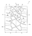
- the tread portion 6 includes a tread pattern 10 shown in FIG.
- FIG. 2 is a plan view of the tread pattern 10 of the tire 1.
- the vertical direction is the tire circumferential direction
- the horizontal direction is the tire width direction.
- the rotation direction of the tire of the tread pattern 10 and the direction of the tire width direction when the vehicle is mounted are not particularly specified.
- the tread pattern 10 includes a center lug groove 11, a shoulder lug groove 13, a pair of circumferential main grooves 15, a center block 23, and a shoulder block 27.
- a plurality of center lug grooves 11 are provided at intervals in the tire circumferential direction.
- the center lug groove 11 extends in the tire width direction on the half tread regions Ta and Tb on both sides (first side and second side) in the tire width direction with respect to the tire equator line CL so as to cross the tire equator line CL. And it has the both ends 11a and 11a extended in the direction inclined with respect to the tire circumferential direction.
- the center lug groove 11 connects second groove bent portions 15b described later of the pair of circumferential main grooves 15 to each other. As will be described later, the pair of circumferential main grooves 15 are different in phase in the tire circumferential direction and extend in a wave shape with the same period. Therefore, the center lug groove 11 extends obliquely with respect to the tire width direction. Yes.
- the center lug groove 11 is a linear groove.
- the groove width of the center lug groove 11 is narrower than that of the shoulder lug groove 13.
- a plurality of shoulder lug grooves 13 are provided at intervals in the tire circumferential direction in each of the half tread regions Ta and Tb.
- the shoulder lug groove 13 extends outward in the tire width direction in each of the half tread regions Ta and Tb, and opens to the adjacent grounding end of the grounding ends 10a and 10b on both sides in the tire width direction.
- the grounding terminals 10a and 10b are determined as follows.
- the ground contact ends 10a and 10b are tire width direction ends of the ground contact surface when the tire 1 is assembled to a regular rim, filled with a regular internal pressure, and grounded on a horizontal plane under the condition that the load is 100% of the regular load. .
- the regular rim referred to here means “measurement rim” defined in JATMA, “Design Rim” defined in TRA, or “Measuring Rim” defined in ETRTO.
- the normal internal pressure means “maximum air pressure” defined by JATMA, the maximum value of “TIRE LOAD LIMITS AT VARIOUS COLD INFLATION PRESSURES” defined by TRA, or “INFLATION PRESSURES” defined by ETRTO.
- the normal load means “maximum load capacity” defined in JATMA, the maximum value of “TIRE LOAD LIMITS AT VARIOUS COLD INFLATION PRESSURES” defined in TRA, or “LOAD CAPACITY” defined in ETRTO.
- the tire width direction positions of the ground contact ends 10a and 10b coincide with the tire width direction positions of both ends of the tread width described later.
- the position in the tire circumferential direction of one shoulder lug groove 13 arranged in one half-tread region is adjacent to the two adjacent half-tread regions.
- the two shoulder lug grooves 13 are located between the positions in the tire circumferential direction.
- the shoulder lug groove 13 is located in the tire width direction of the end 11a of the center lug groove 11 at the position in the tire width direction of the inner end 13a of the shoulder lug groove 13 in each of the half tread regions Ta and Tb.
- the shoulder lug groove 13 is located in the shoulder region located between adjacent center lug grooves 11 adjacent to each other in the tire circumferential direction in the tire circumferential direction.
- the circumferential main groove 15 to be described later is formed by alternately connecting the end 11a of the center lug groove 11 and the inner end 13a of the shoulder lug groove 13 in the tire width direction in each of the half tread regions Ta and Tb.
- the shoulder lug groove 13 has a groove width that changes in the direction in which the groove extends in FIG. 2, but may be constant.
- the circumferential main grooves 15 are provided in each of the half tread regions Ta and Tb on both sides in the tire width direction with respect to the tire equator line CL as a pair.
- the circumferential main grooves 15 are arranged in the tire width direction so as to alternately connect the ends 11a of the center lug grooves 11 and the inner ends 13a of the shoulder lug grooves 13 in the half tread regions Ta and Tb.
- a first groove bent portion 15a that is curved or bent outward and a second groove bent portion 15b that is bent or bent inside in the tire width direction are disposed and formed in a wave shape over the entire circumference in the tire circumferential direction.
- the circumferential main groove 15 is connected to the shoulder lug groove 13 at the first groove bent portion 15a that is curved to protrude outward in the tire width direction, and is bent to be convex inward in the tire width direction. It connects with the center lug groove 11 by the 2 groove bending part 15b.
- the groove having a wave shape means a shape in which the groove meanders.
- the circumferential main groove 15 has a plurality of first groove bent portions 15a and second groove bent portions 15b on the tire circumference, and extends in the tire circumferential direction while meandering so as to form a wave shape by alternately connecting them.
- the first groove bent portion 15a and the second groove bent portion 15b may be a bent shape, a rounded curved shape, or a bent shape. It may be a combination of curved shapes.
- the curved shape also includes a shape obtained by rounding the top of the bent shape, for example, by defining a curvature radius.
- the combination of the bent shape and the curved shape means a shape in which one side extends linearly from the top of the groove bent portion and the other side curves and extends from the top.
- the groove bent portion may have the same shape, or may have different types of shapes.
- portions other than the groove bent portion of the circumferential main groove 15 may be linear or curved. When both the groove bent portion and the portion other than the groove bent portion are curved, the two curved shapes may be curved with the same radius of curvature.
- the circumferential main groove 15 extends in a wave shape with the same period and with a phase shifted in the tire circumferential direction. Specifically, the position in the tire circumferential direction of the second groove bent portion 15b is displaced in the tire circumferential direction with respect to the second groove bent portion 15b in the opposite half tread region.
- the circumferential main grooves 15 may extend in a wave shape with the same period and the same phase in the tire circumferential direction, or may extend in a wave shape with different periods.
- the groove width of the circumferential main groove 15 is narrower than the shoulder lug groove 13. For this reason, the contact pressure of the center block 23 during traveling is relaxed, and the wear life of the tire 1 is extended.
- the center block 23 is defined by the center lug grooves 11 and 11 and the circumferential main groove 15 adjacent to each other in the tire circumferential direction, and a plurality of the center blocks 23 are formed in a row in the tire circumferential direction.
- the tire equator line CL passes.
- the center block 23 has an anisotropic shape inclined with respect to the tire width direction because the center lug groove 11 is inclined with respect to the tire width direction.
- the shoulder block 27 includes a pair of adjacent shoulder lug grooves 13 adjacent to each other in the tire circumferential direction, the circumferential main groove 15 and the tire width direction of the tread portion 6 in each of the half tread regions Ta and Tb. Are formed by a plurality of lines in the circumferential direction of the tire. In the example shown in FIG. 2, the shoulder block 27 is inclined to a side different from the side where the center block 23 is inclined with respect to the tire equator line CL.
- each region of the center block 23 further includes any one of the circumferential main grooves 15 and a center lug groove adjacent to the tire circumferential direction.
- 11 and 11 are provided with two first narrow grooves 28a and 28b that are curved and have no bent portions, the groove width being narrower than the shoulder lug groove 13.
- the curve without a bent portion means a curve having a radius of curvature of 100 mm or more or a curve formed by combining a plurality of such curves with respect to a shape curve along the groove at the center position of the groove width.
- the curved shape of the first narrow grooves 28a, 28b is preferably convex toward only one of the right and left sides with respect to the extending direction of the grooves.
- the curved shape of the first narrow groove 28a is a convex shape toward the left side of the first fine groove 28a when proceeding along the extending direction of the groove from the right side to the left side in FIG.
- the curved shape of the first narrow groove 28b is convex toward the right side of the first narrow groove 28b when proceeding along the extending direction of the groove from the right side to the left side in FIG. ing.
- the first narrow grooves 28a, 28b are preferably spaced apart from each other, i.e., not intersecting or contacting each other, as in the example shown in FIG. 2, but according to one embodiment, intersecting or contacting each other. You may do it.
- the curved first fine grooves 28a and 28b having no bent portions are provided in the respective areas of the center block 23, heat generated in a wide area of the center block 23 flows through the first fine grooves 28a and 28b.
- the air can be discharged to the outside, and the heat resistance can be improved.
- the first narrow grooves 28a and 28b open to any one of the circumferential main grooves 15 and one of the center lug grooves 11 and 11 adjacent in the tire circumferential direction, the heat generated in the center block 23 is generated.
- the heat dissipation by the air discharged to the outside is further improved.
- the circumferential main groove 15 has a wave shape, the surface area of the groove wall surface is increased, and the heat dissipation performance for discharging the heat generated in the center block 23 to the outside by the air flowing through the circumferential main groove 15 is improved. , Heat resistance is improved.
- first narrow grooves 28a and 28b are provided in the region of the center block 23, so that the formation of wear nuclei is suppressed and wear resistance is reduced. Can be improved.
- first narrow grooves 28a and 28b have a curved shape without a bent portion, there is no bent portion where stress concentrates in the region of the center block 23, and the formation of wear nuclei is suppressed. Can be suppressed and the wear resistance can be improved.
- the center lug groove 11 has a linear shape, there is no portion in which the block rigidity of the center block 23 is locally reduced as compared with the case where the center lug groove 11 has a curved shape or a bent shape.
- the block rigidity at 1 is nearly uniform, the formation of wear nuclei can be suppressed and the wear resistance can be improved.
- the groove width of the center lug groove 11 is narrower than the groove width of the shoulder lug groove 13, the ground contact surface of the center block 23 that comes into contact with the ground can be widened, and the rise of the contact pressure is alleviated and wear resistance is increased. Improves.
- the first narrow grooves 28a, 28b are preferably opened in different circumferential main grooves 15, 15 as shown in FIG. Thereby, since the air flowing through the first narrow grooves 28a and 28b flows into the circumferential main grooves 15 and 15 different from each other, the heat dissipation can be further improved and the heat resistance can be improved.
- the portions of the circumferential main grooves 15, 15 where the first narrow grooves 28a, 28b open to the circumferential main grooves 15, 15 are preferably inclined to the same side in the tire width direction with respect to the tire circumferential direction.
- the portions where the first narrow grooves 28a and 28b open to the circumferential main grooves 15 and 15 are both inclined in the upper right direction with respect to the upward direction in the drawing of FIG.
- the two first narrow grooves 28a and 28b open to the adjacent center lug grooves 11 different from each other.
- the first narrow groove 28 a opens in the center lug groove 11 that is in contact with the center block 23 on the upper side in FIG. 2
- the first narrow groove 28 b is in FIG. 2 with respect to the center block 23.
- the center lug groove 11 is in contact with the lower side of the paper.
- the portions of the circumferential main grooves 15 and 15 in which the first narrow grooves 28a and 28b are opened are, respectively, a first groove bent portion 15a (first groove bent portion A) which is one of the first groove bent portions, It is preferably a portion between the second groove bent portion 15b (second groove bent portion B) which is one of the two groove bent portions.
- the first groove bent portion 15a includes a second groove bent portion 15b1 in which the adjacent center lug grooves 11 and 11 in which the first narrow grooves 28a and 28b are opened respectively open in one of the circumferential main grooves 15 (here.
- the groove bending portion adjacent to one direction in the tire circumferential direction represented by the reference numeral 15b1 in FIG.
- the second groove bent portion 15b is a groove bent portion adjacent to the first groove bent portion 15a in the one direction.
- the circumferential main grooves 15 and 15 where the first narrow grooves 28a and 28b open are the first narrow grooves 28a and 28b of the two second groove bent portions in contact with the center block 23, respectively.
- the adjacent center lug groove 11 having an opening is a portion between the second groove bent portion 15b different from the second groove bent portion 15b1 opening in the circumferential main groove 15 and the first groove bent portion 15a.
- the maximum groove depth of the circumferential main groove 15 is preferably shallower than the maximum groove depth of the center lug groove 11, and the maximum groove depth of the center lug groove 11 is preferably shallower than the maximum groove depth of the shoulder lug groove 13.
- FIGS. 3A to 3E are views for explaining changes in the tread pattern accompanying the progress of wear of the pneumatic tire of the present embodiment. Since the center lug groove 11 communicates with the circumferential main groove 15 in the initial stage to the middle stage of wear (the form shown in FIGS. 3A to 3B), it is possible to maintain heat dissipation by the air in the center block 23. it can. Further, as shown in FIG. 3 (d), since the center lug groove 11 remains even at the end of wear, traction performance on a rough road surface can be exhibited.
- D1 / D2 is preferably 0.2 or less. If D1 / D2 is larger than 0.2, the block rigidity of the center block 23 may be reduced, and the wear resistance may be reduced. Further, D1 / D2 is preferably 0.05 or more from the viewpoint of functioning heat radiation by the air flowing through the first narrow grooves 28a and 28b. In FIG. 1, the groove depths of D1 and D2 are represented by exaggerated ratios of D1 / D2.
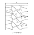
- FIG. 4 is a diagram illustrating the dimensions of the elements of the tread pattern 10.
- L1 / L2 is smaller than 0.5, the air flowing through the first narrow grooves 28a, 28b becomes less responsible for the heat dissipation of the center block 23, so that sufficient heat dissipation cannot be obtained and heat resistance is improved. May not.
- L1 / L2 is larger than 1.0, the block rigidity of the small block element of the center block 23 defined by the two first narrow grooves 28a and 28b may be reduced, and the wear resistance may not be improved.
- the first narrow groove 28a provided in one of the regions of the adjacent center blocks 23 and 23 adjacent to each other in the tire circumferential direction and the first narrow groove 28b provided in the other are a center lug groove. It is preferable to open at the same position in the extending direction of the center lug groove 11 so as to extend continuously with respect to each other. Thereby, air can flow smoothly through the first narrow grooves 28a and 28b, and the heat dissipation of the center block 23 can be improved.
- the second narrow grooves 30a and 30b are preferably provided.
- the second narrow grooves 30 a and 30 b are narrower than the shoulder lug grooves 13.
- the heat dissipation of the shoulder block 27 is improved by the second narrow grooves 30a and 30b.
- the second narrow grooves 30a and 30b and the first narrow grooves 28a and 28b extend at the same position in the extending direction of the circumferential main groove 15 so as to continuously extend with the circumferential main groove 15 interposed therebetween. It is preferable to open. Thereby, since air flows smoothly in a groove
- the length along the grooves of the second narrow grooves 30a and 30b is L3, and the length of the shoulder block 27 in the tire width direction (grounding from the innermost end of the shoulder block 27 in the tire width direction) L3 / Ws is preferably 0.3 or more and 0.8 or less, where Ws is the length in the tire width direction to the ends 10a and 10b.
- L3 / Ws is smaller than 0.3, the surface area of the groove wall surface is reduced, and the heat dissipation of the shoulder block 27 is likely to be lowered.
- L3 / Ws is larger than 0.8, the second fine grooves 30a and 30b are lengthened, the block rigidity of the shoulder block 27 is lowered, and the wear resistance is easily lowered.
- Each of the first narrow grooves 28a and 28b opens at the same position in the extending direction of the center lug groove 11 so as to continuously extend from each other with the center lug groove 11 interposed therebetween, and is adjacent to the tire circumferential direction.
- the first narrow grooves 28a, 28b provided in the area of the center blocks 23, 23 and the second fine grooves 30a, 30b provided in the area of the shoulder block 27 are combined to form an area of the shoulder blocks 27, 27 on both sides. It is preferable to form one continuous narrow groove extending between the two.
- L4 / T is preferably 0.5 or more and 1.1 or less, where L4 is the total length along the groove of the continuous narrow groove and T is the tread width in the tire width direction of the tread portion.
- the tread width T is a peripheral length along the outer shape of the curved tread portion 6 between the ground contact ends 10a and 10b on both sides in the tire width direction.
- L4 / T is smaller than 0.5, the surface area of the groove wall surface is reduced, and the heat dissipation properties of the center block 23 and the shoulder block 27 are likely to be lowered.
- L4 / T is larger than 1.1, the first fine grooves 28a and 28b and the second fine grooves 30a and 30b become long, the block rigidity of the center block 23 and the shoulder block 27 is lowered, and the wear resistance is lowered. It becomes easy.
- the total length L4 does not include the length corresponding to the groove width of the center lug groove 11 and the circumferential main groove 15 where the first fine grooves 28a and 28b and the second fine grooves 30a and 30b intersect.
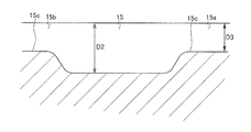
- the tread pattern 10 preferably includes a bottom raised portion 15 c in which the groove is partially shallow in each of the circumferential main grooves 15.
- FIG. 5 is a cross-sectional view for explaining the bottom raised portion of the circumferential main groove 15.
- FIG. 5 shows a cross section when a portion between the first groove bent portion 15a and the second groove bent portion 15b shown in FIG. 2 is cut along a plane including the tire radial direction along the direction in which the circumferential main groove 15 extends. Show.
- the bottom raised portion 15c is formed in the first groove bent portion 15a and the second groove bent portion 15b.
- the circumferential main groove 15 is raised at the portion connected to the center lug groove 11 or the shoulder lug groove 13, so that the vicinity of the first groove bent portion 15 a and the second groove bent portion 15 b of the center block 23.
- the block rigidity of the region is improved. Thereby, abrasion resistance improves.
- the groove depth is deep in the region between the first groove bent portion 15a and the second groove bent portion 15b, the cooling effect of the block is increased, heat dissipation is improved, and heat resistance is improved.
- the bottom raised portion 15c may have a constant groove depth D3 as shown in FIG. 5, or may have a different groove depth.
- the groove depth D ⁇ b> 3 is the shallowest groove depth in the bottom raised portion 15 c and is the minimum groove depth of the circumferential main groove 15.
- the groove bottom has a step in the groove depth direction to have two or more different groove depths, or the groove depth continues in the direction in which the grooves extend. Are changing.
- the total length of the bottom raised portion 15c along the extending direction of the circumferential main groove 15 is not particularly limited, the end of the first groove bent portion 15a located on the outermost side in the tire width direction and the tire width direction Of the length of the portion of the circumferential main groove 15 extending between the end of the second groove bending portion 15b located on the innermost side, including both ends of the portion, and of the groove length of the portion, For example, it is formed in a region having a total length of 30 to 70%.
- the bottom raised portion 15 c is formed in the first groove bent portion 15 a and the second groove bent portion 15 b, but is formed in each of the linear portions forming the wave shape of the circumferential main groove 15. May be. From the viewpoint of improving wear resistance, the bottom raised portion 15c is preferably formed in the first groove bent portion 15a and the second groove bent portion 15b.
- the ratio D3 / T is 0.01 or more and 0.05 or less with respect to the shallowest groove depth D3 in the bottom raised portion 15c and the tread width T of the tread portion 6 in the tire width direction. Is preferred.
- the ratio D3 / T is 0.05 or less, the center block 23 and the shoulder block 27 are supported and the block rigidity becomes an appropriate size, so that the occurrence of early wear due to uneven wear can be suppressed.
- the ratio D3 / T is 0.01 or more, a groove volume necessary to obtain good heat resistance can be ensured.
- the ratio D3 / T is more preferably 0.048 or less.
- the groove widths of the circumferential main groove 15 and the center lug groove 11 are preferably 7 mm or more and 20 mm or less, respectively. Thereby, heat resistance and abrasion resistance can be further improved.
- the width of the circumferential main groove 15 and the center lug groove 11 is, for example, 18 mm. In addition, it is suitable when the tire 1 is used as an off-road tire when the groove width of the circumferential main groove 15 and the center lug groove 11 is in the above range.
- the tire 1 of the present embodiment is suitable for mounting on a construction vehicle or an industrial vehicle.
- Construction vehicles or industrial vehicles are, for example, dump trucks, scrapers, graders, excavator loaders, tire rollers, wheel cranes, truck cranes described in JATMA, or ⁇ COMPACTOR '', ⁇ EARTHMOVING '' as defined in TRA, Includes vehicles such as “GRADER” and “LOADER AND DOZER”.
- Examples and comparative examples In order to investigate the effect of the tire according to the present embodiment, various tires having different tread patterns were experimentally manufactured, and the wear resistance and heat resistance were examined.
- the prototype tire is 33.00R51.
- the rim size was 51 ⁇ 24-5.0 (TRA specified rim), and 700 kPa (TRA specified air pressure) was used as the air pressure.
- wear resistance using a 150-ton dump truck, running on the same rough road (off-road) at a speed of 50 km / hour for 3000 hours, measuring the amount of wear around the center block 23, wear resistance Evaluated.
- wear resistance the reciprocal of the amount of wear was indexed using the comparative example as a reference (index 100). Higher wear resistance index means higher wear resistance.
- heat resistance includes the effect of heat dissipation due to the air flow in the groove.
- the measured travel time was indexed using the comparative example as a reference (index 100). The higher the heat resistance index, the higher the heat resistance.
- the prototype tires are Comparative Example and Examples 1-27.
- Examples 1 to 27 are tread patterns that are changed according to the specifications described in each table with the tread pattern 10 shown in FIG. 2 as a reference.
- the comparative example is a tread pattern that does not include the first narrow grooves 28a and 28b and the second narrow grooves 30a and 30b in the tread pattern 10 shown in FIG. Further, in the comparative example and Examples 1 to 9, the circumferential main groove was not provided with a bottom raised portion, and the groove depth was constant.
- the dimensions of the groove width, groove depth, and groove length in Examples 1 to 27 and the comparative example were set to the same value unless restricted by each specification.
- Tables 1 to 6 show the specifications of the comparative examples and Examples 1 to 27 and their evaluation results.
- “whether or not the first narrow grooves are continuous?” Indicates that the first narrow groove 28a provided in one of the regions of the adjacent center block 23 adjacent in the tire circumferential direction and the first narrow groove provided in the other.
- the first narrow groove 28a and the first narrow groove 28b are the same in the extending direction of the center lug groove 11 between the adjacent center blocks 23 and 23 so that the groove 28b forms one continuous narrow groove. It means whether or not it is open at a position.
- “Whether the first narrow groove is continuous with the second narrow groove?” Indicates that the first narrow grooves 28a and 28b and the second narrow grooves 30a and 30b form one continuous narrow groove.
- the circumferential main groove 15 is opened at the same position in the extending direction. If it is not “continuous shape”, the position of the opening is shifted by a distance of twice the length of each of the first narrow grooves 28a and 28b and the second narrow grooves 30a and 30b.
- D1 / D2 is preferably 0.2 or less from the viewpoint of improvement of wear resistance and heat generation resistance, particularly improvement of wear resistance.
- L1 / L2 is preferably 0.5 to 1.0 from the viewpoint of improvement in wear resistance and heat generation resistance.
- D3 / T is 0.05 or less, preferably 0.048 or less, from the viewpoint of improvement of wear resistance and heat generation resistance, particularly improvement of wear resistance.
- L3 / Ws is preferably 0.3 to 0.8 from the viewpoint of improvement of wear resistance and heat generation resistance, particularly improvement of wear resistance.
- Table 5 it is shown that the second narrow grooves 30a and 30b are provided in the region of the shoulder block 27, and that the first narrow grooves 28a and 28b are formed into continuous narrow grooves, so that wear resistance and heat generation are prevented. It can be seen that it is preferable from the viewpoint of improvement of wear resistance, in particular, wear resistance.
- the first narrow grooves 28a and 28b and the second narrow grooves 30a and 30b are formed into one continuous narrow groove, thereby improving heat resistance. From this point, it can be seen that it is preferable.
- L4 / T is preferably 0.5 to 1.1 from the viewpoint of improvement in wear resistance and heat resistance.
- the heavy load pneumatic tire of the present invention has been described in detail above.
- the heavy load pneumatic tire of the present invention is not limited to the above embodiment or examples, and various improvements can be made without departing from the gist of the present invention. Of course, you may make changes.
Abstract
Description
当該重荷重用空気入りタイヤは、トレッド踏面に、トレッド周方向に連続して延びる二本以上の周溝と、トレッド幅方向に互いに隣接する該周溝のそれぞれに開口する横断溝とで区画されるブロックを有する。前記ブロックに、該ブロックに隣接する前記周溝の溝深さより浅い平均溝深さを有する一本以上の浅溝を設ける。該浅溝の前記平均溝深さは、前記周溝の溝深さの20%より大きく、かつ、該周溝の溝深さの80%未満である。さらに、該浅溝の少なくとも一本は、該ブロックに隣接する前記周溝及び前記横断溝の少なくとも一方に開口する。 In heavy-duty pneumatic tires, there is known a technique for improving mud repellency in a ground contact surface without deteriorating wear resistance due to a decrease in block rigidity (Patent Document 1).
The heavy duty pneumatic tire is partitioned on a tread surface by two or more circumferential grooves continuously extending in the tread circumferential direction and transverse grooves opening to the circumferential grooves adjacent to each other in the tread width direction. Has a block. The block is provided with one or more shallow grooves having an average groove depth shallower than the groove depth of the circumferential groove adjacent to the block. The average groove depth of the shallow groove is greater than 20% of the groove depth of the circumferential groove and less than 80% of the groove depth of the circumferential groove. Further, at least one of the shallow grooves opens in at least one of the circumferential groove and the transverse groove adjacent to the block.
タイヤ周方向に間隔をあけて複数設けられ、タイヤ赤道線を横切るようにタイヤ赤道線を基準としたタイヤ幅方向の第1の側および第2の側の半トレッド領域に、タイヤ幅方向及びタイヤ周方向に対して傾斜した向きに延びて両端を有する直線形状のセンターラグ溝と、
前記半トレッド領域のそれぞれにおいて、タイヤ周方向に間隔をあけて複数設けられ、タイヤ幅方向外側に延びて、タイヤ幅方向外側の端がタイヤ幅方向の両側にある接地端に開口するショルダーラグ溝であって、前記ショルダーラグ溝のタイヤ幅方向内側の端のタイヤ幅方向の位置が、前記センターラグ溝の端のタイヤ幅方向の位置よりも外側にあり、かつ、タイヤ周方向において、前記センターラグ溝のうちタイヤ周方向に隣りあう隣接センターラグ溝の間に1つずつ設けられたショルダーラグ溝と、
前記半トレッド領域のそれぞれに設けられ、前記センターラグ溝の端と、前記ショルダーラグ溝のタイヤ幅方向の内側の端を交互に接続するように、タイヤ幅方向の外側に湾曲あるいは屈曲した第1溝曲がり部とタイヤ幅方向の内側に湾曲あるいは屈曲した第2溝曲がり部とが配置され、前記第1溝曲がり部で前記ショルダーラグ溝が開口し、前記第2溝曲がり部で前記センターラグ溝が開口し、タイヤ周方向にわたって波形状に形成された一対の周方向主溝と、
前記センターラグ溝のうちタイヤ周方向に隣り合う一対の隣接センターラグ溝と前記一対の周方向主溝によって画されてタイヤ周方向に一列に複数形成されたセンターブロックと、
を含むトレッドパターンを備える。
前記センターラグ溝及び前記周方向主溝の溝幅は、前記ショルダーラグ溝より狭く、
前記センターブロックのそれぞれの領域には、前記周方向主溝の1つと、前記隣接センターラグ溝の1つとに開口し、溝幅が前記ショルダーラグ溝より狭い、屈曲部のない曲線状の第1細溝が2つ設けられている。 One aspect of the present invention is a heavy duty pneumatic tire with a tread pattern,
A plurality of tire circumferential directions are provided at intervals in the tire circumferential direction, and the tire width direction and the tire are arranged in a half tread region on the first side and the second side in the tire width direction with respect to the tire equator line so as to cross the tire equator line. A linear center lug groove extending in a direction inclined with respect to the circumferential direction and having both ends;
In each of the half tread regions, a plurality of shoulder lug grooves that are provided at intervals in the tire circumferential direction, extend outward in the tire width direction, and open to the ground contact ends on both sides in the tire width direction. The position in the tire width direction of the end in the tire width direction of the shoulder lug groove is outside the position in the tire width direction of the end of the center lug groove, and in the tire circumferential direction, the center Shoulder lug grooves provided one by one between adjacent center lug grooves adjacent in the tire circumferential direction among the lug grooves;
A first curve that is provided in each of the half tread regions and is curved or bent outward in the tire width direction so as to alternately connect the end of the center lug groove and the inner end of the shoulder lug groove in the tire width direction. A groove bent portion and a second groove bent portion that is curved or bent inward in the tire width direction are disposed, the shoulder lug groove is opened at the first groove bent portion, and the center lug groove at the second groove bent portion. A pair of circumferential main grooves formed in a wave shape over the tire circumferential direction,
A center block defined by a pair of adjacent center lug grooves adjacent to each other in the tire circumferential direction and the pair of circumferential main grooves among the center lug grooves and formed in a row in the tire circumferential direction,
A tread pattern including
The groove width of the center lug groove and the circumferential main groove is narrower than the shoulder lug groove,
In each region of the center block, there is a curved first without opening at one of the circumferential main grooves and one of the adjacent center lug grooves, the groove width being narrower than the shoulder lug grooves. Two narrow grooves are provided.
前記第1溝曲がり部Aは、前記第1細溝のそれぞれが開口する隣接センターラグ溝が前記周方向主溝の1つに開口する前記第2溝曲がり部の1つに対してタイヤ周方向の一方の方向に隣り合う溝曲がり部である。
このとき、前記第2溝曲がり部Bは、前記第1溝曲がり部Aに対してさらに前記一方の方向に隣り合う溝曲がり部である、ことが好ましい。 The portions of the circumferential main groove in which each of the first narrow grooves opens are a first groove bent portion A that is one of the first groove bent portions and one of the second groove bent portions. It is the part between the two groove bends B,
The first groove bending portion A is a tire circumferential direction with respect to one of the second groove bending portions in which an adjacent center lug groove opened in each of the first narrow grooves opens in one of the circumferential main grooves. It is a groove bending part adjacent in one direction of.
At this time, the second groove bent portion B is preferably a groove bent portion that is further adjacent to the first groove bent portion A in the one direction.
前記ショルダーラグ溝のうち、タイヤ周方向に隣り合う隣接ショルダーラグ溝の間に設けられるタイヤ幅方向の両側のショルダーブロックの領域には、前記ショルダーブロック内で閉塞し、前記周方向主溝の1つに開口する、溝幅が前記ショルダーラグ溝より狭い第2細溝が設けられ、
前記隣接センターブロックの領域に設けられる前記第1細溝と前記第2細溝が組となって、前記両側のショルダーブロックの領域の間を延びる1つの連続細溝を形成している。
このとき、前記連続細溝の溝に沿った全長をL4とし、前記トレッド部のタイヤ幅方向のトレッド幅をTとしたとき、L4/Tは0.5以上1.1以下である、ことが好ましい。 In addition, one of the first narrow grooves provided in each of the adjacent center blocks adjacent to each other in the tire circumferential direction of the center blocks may extend continuously with respect to one of the center lug grooves. In the same position of one of the center lug grooves,
Of the shoulder lug grooves, the shoulder block regions on both sides in the tire width direction provided between adjacent shoulder lug grooves adjacent in the tire circumferential direction are closed within the shoulder block, and 1 of the circumferential main grooves. A second narrow groove having a groove width narrower than the shoulder lug groove is provided.
The first narrow groove and the second narrow groove provided in the adjacent center block region form a pair to form one continuous narrow groove extending between the shoulder block regions on both sides.
At this time, L4 / T is 0.5 or more and 1.1 or less, where L4 is the total length along the groove of the continuous narrow groove and T is the tread width in the tire width direction of the tread portion. preferable.
図1は、本実施形態の重荷重用空気入りタイヤ(以降、タイヤともいう)1のタイヤ回転軸を含み、タイヤ径方向を含む平面でタイヤ1を切断したときのタイヤ1のプロファイル断面の一例を示す図である。 Hereinafter, the heavy duty pneumatic tire of the present invention will be described in detail.
FIG. 1 shows an example of a profile cross section of the tire 1 when the tire 1 is cut along a plane including the tire rotation axis of the heavy duty pneumatic tire (hereinafter also referred to as a tire) 1 of the present embodiment and including the tire radial direction. FIG.
タイヤ幅方向は、タイヤの回転軸と平行な方向である。タイヤ幅方向外側は、タイヤ幅方向において、比較する位置に対して、タイヤ赤道面を表すタイヤ赤道線CLから離れる側である。また、タイヤ幅方向内側は、比較する位置に対して、タイヤ幅方向において、タイヤ赤道線CLに近づく側である。タイヤ周方向は、タイヤの回転軸を回転の中心としてタイヤが回転する方向である。タイヤ周方向は、互いに方向の異なる第1の方向と第2の方向を備える。タイヤ径方向は、タイヤの回転軸に直交する方向である。タイヤ径方向外側は、比較する位置に対して、タイヤ径方向に沿って前記回転軸から離れる側をいう。また、タイヤ径方向内側は、比較する位置に対して、タイヤ径方向に沿って前記回転軸に近づく側をいう。 In this specification, each direction and side are defined as follows.
The tire width direction is a direction parallel to the rotation axis of the tire. The outer side in the tire width direction is the side away from the tire equator line CL representing the tire equator plane with respect to the position to be compared in the tire width direction. The inner side in the tire width direction is the side closer to the tire equator line CL in the tire width direction with respect to the position to be compared. The tire circumferential direction is a direction in which the tire rotates with the rotation axis of the tire as the center of rotation. The tire circumferential direction includes a first direction and a second direction that are different from each other. The tire radial direction is a direction orthogonal to the rotation axis of the tire. The outer side in the tire radial direction refers to the side away from the rotation axis along the tire radial direction with respect to the position to be compared. Further, the inner side in the tire radial direction refers to a side closer to the rotation axis along the tire radial direction with respect to the position to be compared.
タイヤ1は、構造体として、カーカスプライ3と、ベルト部4と、一対のビードコア5とを有し、これらの構造体の周りに、トレッド部6、サイド部7、ビードフィラー8、インナーライナ9等の各ゴム層を有する。 (Tire structure)
The tire 1 includes a
トレッド部6は、以下に説明するようにトレッドパターン10を備えている。
このようなタイヤ1の構成は、一例であり、タイヤ1は、これ以外の公知の構成を備えてもよい。 The
The
Such a configuration of the tire 1 is an example, and the tire 1 may include other known configurations.
トレッド部6は、図2に示されるトレッドパターン10を備えている。図2は、タイヤ1のトレッドパターン10を平面展開した図である。なお、図2において、上下方向はタイヤ周方向であり、左右方向はタイヤ幅方向である。トレッドパターン10のタイヤの回転方向および車両装着時のタイヤ幅方向の向きは、特に指定されない。 (Tread pattern)
The
ここで、接地端10a,10bは以下のように定められる。接地端10a,10bは、タイヤ1を正規リムに組み付け、正規内圧を充填し、正規荷重の100%を負荷荷重とした条件において水平面に接地させたときの接地面のタイヤ幅方向端部である。なお、ここでいう正規リムとは、JATMAに規定される「測定リム」、TRAに規定される「Design Rim」、あるいはETRTOに規定される「Measuring Rim」をいう。また、正規内圧とは、JATMAに規定される「最高空気圧」、TRAに規定される「TIRE LOAD LIMITS AT VARIOUS COLD INFLATION PRESSURES」の最大値、あるいはETRTOに規定される「INFLATION PRESSURES」をいう。また、正規荷重とは、JATMAに規定される「最大負荷能力」、TRAに規定される「TIRE LOAD LIMITS AT VARIOUS COLD INFLATION PRESSURES」の最大値、あるいはETRTOに規定される「LOAD CAPACITY」をいう。なお、接地端10a,10bのタイヤ幅方向位置は、後述するトレッド幅の両端のタイヤ幅方向位置と一致している。 A plurality of
Here, the
さらに、ショルダーラグ溝13は、半トレッド領域Ta,Tbのそれぞれにおいて、ショルダーラグ溝13が有するタイヤ幅方向内側の端13aのタイヤ幅方向の位置が、センターラグ溝11の端11aのタイヤ幅方向の位置よりもタイヤ幅方向の外側にあり、かつ、ショルダーラグ溝13は、タイヤ周方向において、センターラグ溝11のうちタイヤ周方向に隣りあう隣接センターラグ溝11の間に位置するショルダー領域に1つずつ設けられている。これにより、後述する周方向主溝15は、半トレッド領域Ta,Tbのそれぞれにおいて、センターラグ溝11の端11aとショルダーラグ溝13のタイヤ幅方向の内側の端13aを交互に接続して波形状を成す。ショルダーラグ溝13は、図2において、溝が延びる方向に溝幅が変化しているが、一定であってもよい。 In the
Further, the
周方向主溝15の溝幅は、ショルダーラグ溝13よりも溝幅が狭い。このため、走行時のセンターブロック23の接地圧が緩和され、タイヤ1の摩耗寿命が延びる。 In FIG. 2, the circumferential
The groove width of the circumferential
このとき、第2細溝30a,30bは、第1細溝28a,28bとともに、周方向主溝15を挟んで互いに連続して延びるように、周方向主溝15の延在方向の同じ位置で開口することが好ましい。これにより、溝を空気が滑らかに流れるので、ショルダーブロック27の放熱性が向上する。 In the region of the
At this time, the second
本実施形態のタイヤの効果を調べるために、トレッドパターンの異なるタイヤを種々試作し、耐摩耗性と耐発熱性を調べた。試作したタイヤは、33.00R51である。リムサイズ51×24-5.0(TRA規定リム)に装着し、700kPa(TRA規定空気圧)を、空気圧とした。
耐摩耗性については、150トン用ダンプトラックを用いて、同じ悪路(オフロード)路面の走行を速度50km/時で3000時間行ない、センターブロック23周りの摩耗量を測定して、耐摩耗性を評価した。耐摩耗性の評価では、摩耗量の逆数を、比較例を基準(指数100)として指数化した。耐摩耗性の指数が高いほど、耐摩耗性が高いことを意味する。
一方、耐発熱性については、TRAの規格荷重(38750kgf)の110%を負荷荷重として、室内ドラムで速度5km/時から、12時間ごとに速度を1km/時ずつ増加させて、タイヤが熱により破壊されるまでの走行時間を測定した。したがって、耐発熱性は、溝内の空気の流れによる放熱性の効果も含んでいる。耐発熱性の評価では、測定した走行時間を、比較例を基準(指数100)として指数化した。耐発熱性の指数が高いほど、耐発熱性が高いことを意味する。 (Examples and comparative examples)
In order to investigate the effect of the tire according to the present embodiment, various tires having different tread patterns were experimentally manufactured, and the wear resistance and heat resistance were examined. The prototype tire is 33.00R51. The rim size was 51 × 24-5.0 (TRA specified rim), and 700 kPa (TRA specified air pressure) was used as the air pressure.
With regard to wear resistance, using a 150-ton dump truck, running on the same rough road (off-road) at a speed of 50 km / hour for 3000 hours, measuring the amount of wear around the
On the other hand, with regard to heat resistance, 110% of the TRA standard load (38750 kgf) was used as the load, and the speed was increased by 1 km / hour every 12 hours from 5 km / hour on the indoor drum. The running time until destruction was measured. Therefore, heat resistance includes the effect of heat dissipation due to the air flow in the groove. In the evaluation of heat resistance, the measured travel time was indexed using the comparative example as a reference (index 100). The higher the heat resistance index, the higher the heat resistance.
実施例1~27は、図2に示すトレッドパターン10を基準として、各表に記載の仕様に合わせて変更したトレッドパターンである。比較例は、図2に示すトレッドパターン10において、第1細溝28a,28b及び第2細溝30a,30bを有しないトレッドパターンである。また、比較例及び実施例1~9において、周方向主溝には底上げ部を設けず、その溝深さは一定の溝深さとした。実施例1~27及び比較例の溝幅、溝深さ、及び溝長さの寸法は、各仕様で制限されない限り、同じ値に揃えた。 The prototype tires are Comparative Example and Examples 1-27.
Examples 1 to 27 are tread patterns that are changed according to the specifications described in each table with the
表中の“第1細溝同士は連続形状か否か?”は、タイヤ周方向に隣接する隣接センターブロック23の領域の一方に設けられる第1細溝28aと、他方に設けられる第1細溝28bが、1つの連続形状の細溝を形成するように、第1細溝28aと第1細溝28bは、隣接センターブロック23,23の間にあるセンターラグ溝11の延在方向の同じ位置で開口しているか否かを意味する。表中の“第1細溝は第2細溝と連続形状か否か?”は、第1細溝28a、28bと第2細溝30a、30bが、1つの連続形状の細溝を形成するように、周方向主溝15の延在方向の同じ位置で開口しているか否かを意味する。“連続形状”でない場合、開口の位置は、第1細溝28a,28b及び第2細溝30a,30bの溝幅のそれぞれの長さの2倍の距離位置ずれしている。 Tables 1 to 6 show the specifications of the comparative examples and Examples 1 to 27 and their evaluation results.
In the table, “whether or not the first narrow grooves are continuous?” Indicates that the first
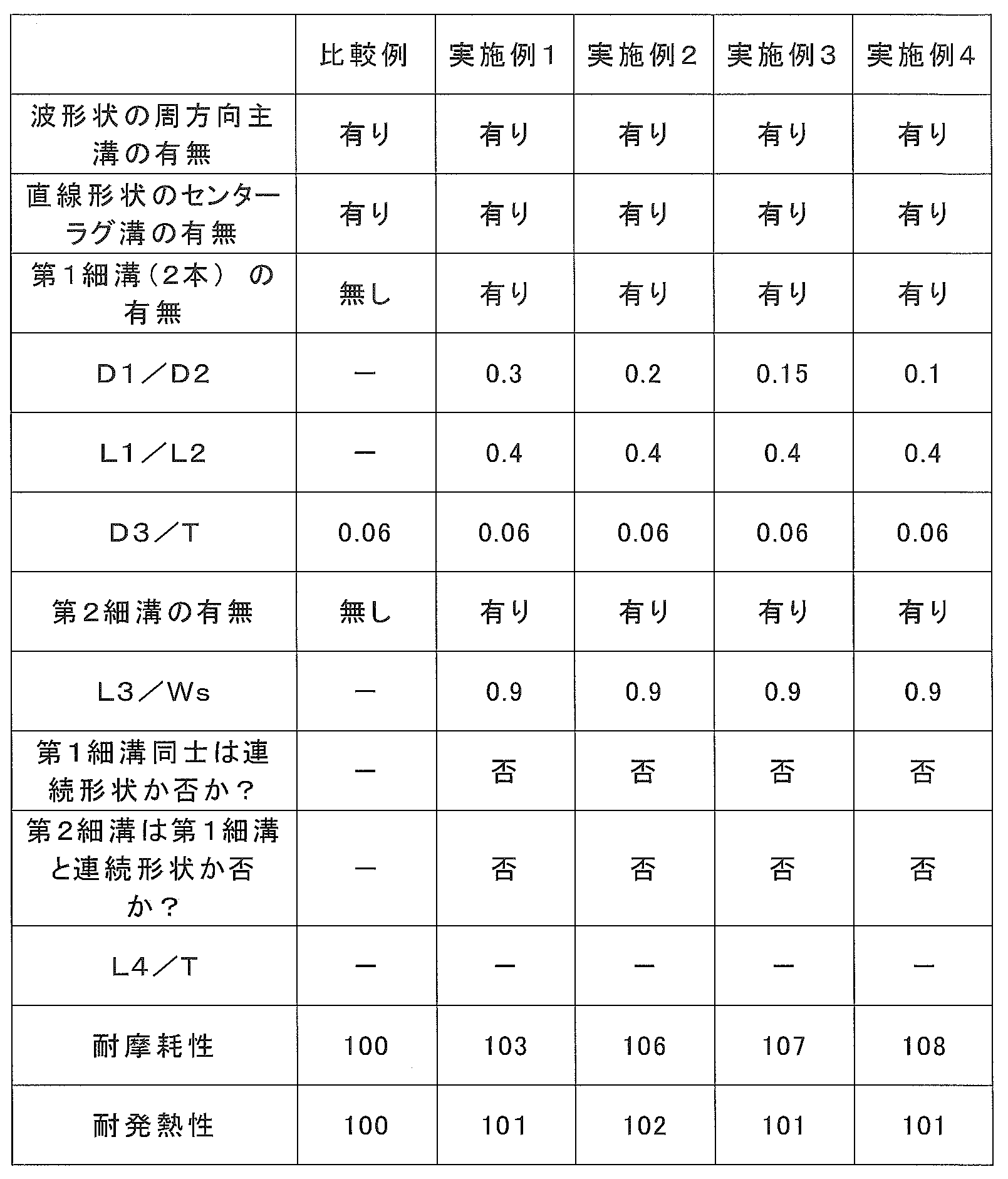
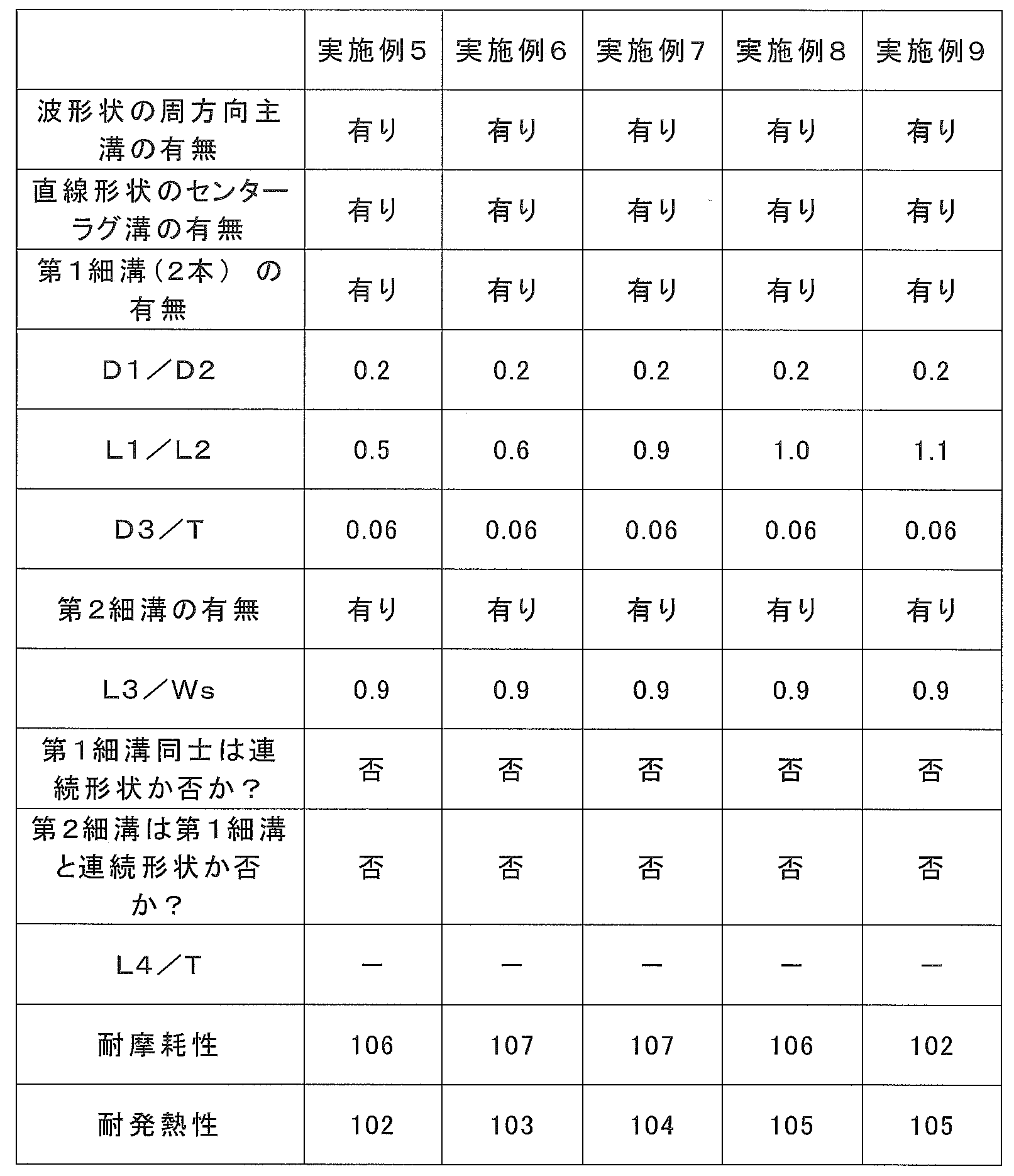
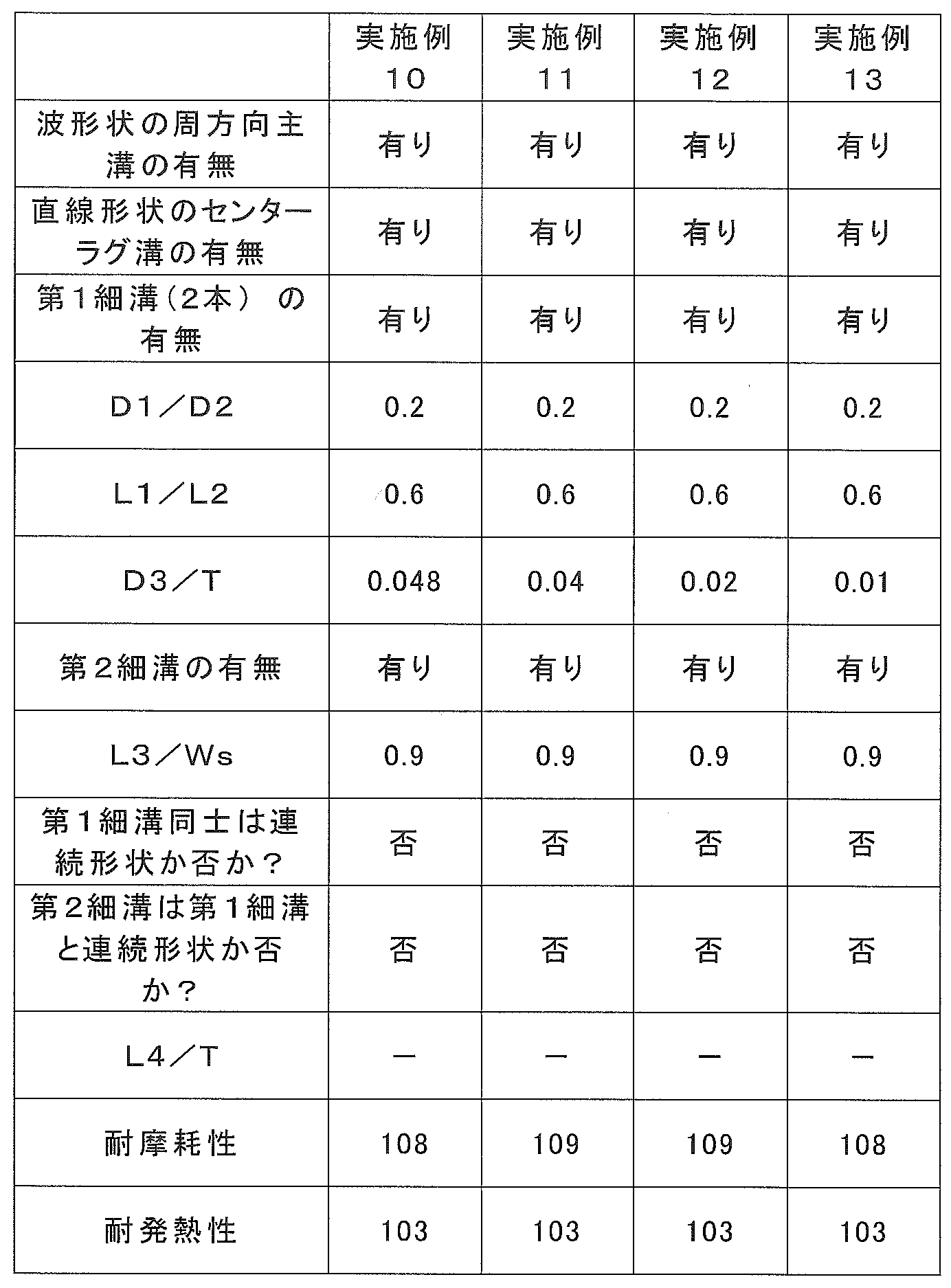

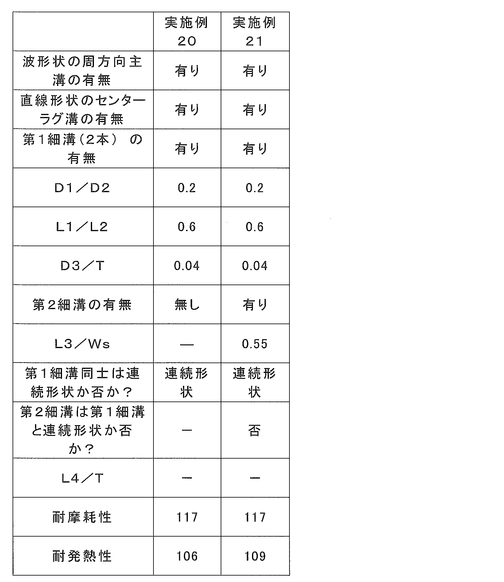

表2より、L1/L2は0.5~1.0であることが、耐摩耗性及び耐発熱性の向上の点から好ましいことがわかる。
表3より、D3/Tは0.05以下、好ましくは0.048以下であることが、耐摩耗性及び耐発熱性の向上、特に耐摩耗性の向上の点から好ましいことがわかる。
表4より、L3/Wsは0.3~0.8であることが、耐摩耗性及び耐発熱性の向上、特に耐摩耗性の向上の点から好ましいことがわかる。
表5より、ショルダーブロック27の領域に、第2細溝30a,30bが設けられること、さらに、第1細溝28a,28b同士を連続形状の細溝とすることが、耐摩耗性及び耐発熱性の向上、特に耐摩耗性の向上の点から好ましいことがわかる。
表5の実施例21及び表6の実施例22の比較より、第1細溝28a,28bと第2細溝30a,30bを1つの連続形状の細溝とすることが、耐発熱性の向上の点から好ましいことがわかる。
表6より、L4/Tは0.5~1.1であることが、耐摩耗性及び耐発熱性の向上の点から好ましいことがわかる。 From Table 1, it can be seen that by providing the first
From Table 2, it can be seen that L1 / L2 is preferably 0.5 to 1.0 from the viewpoint of improvement in wear resistance and heat generation resistance.
From Table 3, it can be seen that D3 / T is 0.05 or less, preferably 0.048 or less, from the viewpoint of improvement of wear resistance and heat generation resistance, particularly improvement of wear resistance.
From Table 4, it can be seen that L3 / Ws is preferably 0.3 to 0.8 from the viewpoint of improvement of wear resistance and heat generation resistance, particularly improvement of wear resistance.
From Table 5, it is shown that the second
From the comparison between Example 21 in Table 5 and Example 22 in Table 6, the first
From Table 6, it can be seen that L4 / T is preferably 0.5 to 1.1 from the viewpoint of improvement in wear resistance and heat resistance.
3 カーカスプライ
4 ベルト部
5 ビードコア
6 トレッド部
7 サイド部
8 ビードフィラー
9 インナーライナ
10 トレッドパターン
10a,10b 接地端
11 センターラグ溝
11a 端
13 ショルダーラグ溝
13a 端
15 周方向主溝
15a 第1溝曲がり部
15b 第2溝曲がり部
15c 底上げ部
23 センターブロック
27 ショルダーブロック
28a,28b 第1細溝
30a,30b 第2細溝
31 第1の交差ベルト層
33 第2の交差ベルト層
35 第3の交差ベルト層
37 シート状ゴム DESCRIPTION OF SYMBOLS 1 Heavy load
Claims (17)
- トレッドパターン付き重荷重用空気入りタイヤであって、
タイヤ周方向に間隔をあけて複数設けられ、タイヤ赤道線を横切るようにタイヤ赤道線を基準としたタイヤ幅方向の第1の側および第2の側の半トレッド領域に、タイヤ幅方向及びタイヤ周方向に対して傾斜した向きに延びて両端を有する直線形状のセンターラグ溝と、
前記半トレッド領域のそれぞれにおいて、タイヤ周方向に間隔をあけて複数設けられ、タイヤ幅方向外側に延びて、タイヤ幅方向外側の端がタイヤ幅方向の両側にある接地端に開口するショルダーラグ溝であって、前記ショルダーラグ溝のタイヤ幅方向内側の端のタイヤ幅方向の位置が、前記センターラグ溝の端のタイヤ幅方向の位置よりも外側にあり、かつ、タイヤ周方向において、前記センターラグ溝のうちタイヤ周方向に隣りあう隣接センターラグ溝の間に1つずつ設けられたショルダーラグ溝と、
前記半トレッド領域のそれぞれに設けられ、前記センターラグ溝の端と、前記ショルダーラグ溝のタイヤ幅方向の内側の端を交互に接続するように、タイヤ幅方向の外側に湾曲あるいは屈曲した第1溝曲がり部とタイヤ幅方向の内側に湾曲あるいは屈曲した第2溝曲がり部とが配置され、前記第1溝曲がり部で前記ショルダーラグ溝が開口し、前記第2溝曲がり部で前記センターラグ溝が開口し、タイヤ周方向にわたって波形状に形成された一対の周方向主溝と、
前記センターラグ溝のうちタイヤ周方向に隣り合う一対の隣接センターラグ溝と前記一対の周方向主溝によって画されてタイヤ周方向に一列に複数形成されたセンターブロックと、
を含むトレッドパターンを備え、
前記センターラグ溝及び前記周方向主溝の溝幅は、前記ショルダーラグ溝より狭く、
前記センターブロックのそれぞれの領域には、前記周方向主溝の1つと、前記隣接センターラグ溝の1つとに開口し、溝幅が前記ショルダーラグ溝より狭い、屈曲部のない曲線状の第1細溝が2つ設けられている、ことを特徴とする重荷重用空気入りタイヤ。 A heavy duty pneumatic tire with a tread pattern,
A plurality of tire circumferential directions are provided at intervals in the tire circumferential direction, and the tire width direction and the tire are arranged in a half tread region on the first side and the second side in the tire width direction with respect to the tire equator line so as to cross the tire equator line. A linear center lug groove extending in a direction inclined with respect to the circumferential direction and having both ends;
In each of the half tread regions, a plurality of shoulder lug grooves that are provided at intervals in the tire circumferential direction, extend outward in the tire width direction, and open to the ground contact ends on both sides in the tire width direction. The position in the tire width direction of the end in the tire width direction of the shoulder lug groove is outside the position in the tire width direction of the end of the center lug groove, and in the tire circumferential direction, the center Shoulder lug grooves provided one by one between adjacent center lug grooves adjacent in the tire circumferential direction among the lug grooves;
A first curve that is provided in each of the half tread regions and is curved or bent outward in the tire width direction so as to alternately connect the end of the center lug groove and the inner end of the shoulder lug groove in the tire width direction. A groove bent portion and a second groove bent portion that is curved or bent inward in the tire width direction are disposed, the shoulder lug groove is opened at the first groove bent portion, and the center lug groove at the second groove bent portion. A pair of circumferential main grooves formed in a wave shape over the tire circumferential direction,
A center block defined by a pair of adjacent center lug grooves adjacent to each other in the tire circumferential direction and the pair of circumferential main grooves among the center lug grooves and formed in a row in the tire circumferential direction,
With tread pattern including
The groove width of the center lug groove and the circumferential main groove is narrower than the shoulder lug groove,
In each region of the center block, there is a curved first without opening at one of the circumferential main grooves and one of the adjacent center lug grooves, the groove width being narrower than the shoulder lug grooves. A heavy-duty pneumatic tire characterized in that two narrow grooves are provided. - 前記2つの第1細溝は、互いに異なる周方向主溝に開口する、請求項1に記載の重荷重用空気入りタイヤ。 2. The heavy duty pneumatic tire according to claim 1, wherein the two first narrow grooves open to different circumferential main grooves.
- 前記2つの第1細溝が前記周方向主溝に開口する前記周方向主溝の部分は、タイヤ周方向に対してタイヤ幅方向の同じ側に傾斜している、請求項1または2に記載の重荷重用空気入りタイヤ。 The portion of the circumferential main groove where the two first narrow grooves open to the circumferential main groove is inclined to the same side in the tire width direction with respect to the tire circumferential direction. Heavy duty pneumatic tires.
- 前記2つの第1細溝は、互いに異なる前記隣接センターラグ溝に開口する、請求項1~3のいずれか1項に記載の重荷重用空気入りタイヤ。 The heavy duty pneumatic tire according to any one of claims 1 to 3, wherein the two first narrow grooves open to the adjacent center lug grooves different from each other.
- 前記第1細溝のそれぞれが開口する前記周方向主溝の部分は、前記第1溝曲がり部の1つである第1溝曲がり部Aと、前記第2溝曲がり部の1つである第2溝曲がり部Bとの間の部分であり、
前記第1溝曲がり部Aは、前記第1細溝のそれぞれが開口する隣接センターラグ溝が前記周方向主溝の1つに開口する前記第2溝曲がり部の1つに対してタイヤ周方向の一方の方向に隣り合う溝曲がり部であり、
前記第2溝曲がり部Bは、前記第1溝曲がり部Aに対してさらに前記一方の方向に隣り合う溝曲がり部である、請求項1~4のいずれか1項に記載の重荷重用空気入りタイヤ。 The portions of the circumferential main groove in which each of the first narrow grooves opens are a first groove bent portion A that is one of the first groove bent portions and one of the second groove bent portions. It is the part between the two groove bends B,
The first groove bending portion A is a tire circumferential direction with respect to one of the second groove bending portions in which an adjacent center lug groove opened in each of the first narrow grooves opens in one of the circumferential main grooves. Groove bends adjacent in one direction of
The heavy load pneumatic according to any one of claims 1 to 4, wherein the second groove bent portion B is a groove bent portion further adjacent to the first groove bent portion A in the one direction. tire. - 前記周方向主溝の最大溝深さは、前記センターラグ溝の最大溝深さよりも浅く、前記センターラグ溝の最大溝深さは、前記ショルダーラグ溝の最大溝深さよりも浅い、請求項1~5のいずれか1項に記載の重荷重用空気入りタイヤ。 The maximum groove depth of the circumferential main groove is shallower than the maximum groove depth of the center lug groove, and the maximum groove depth of the center lug groove is shallower than the maximum groove depth of the shoulder lug groove. The heavy duty pneumatic tire according to any one of 1 to 5.
- 前記第1細溝の最大溝深さをD1とし、前記周方向主溝の最大溝深さをD2としたとき、D1/D2は0.2以下である、請求項1~6のいずれか1項に記載の重荷重用空気入りタイヤ。 Any one of claims 1 to 6, wherein D1 / D2 is 0.2 or less, where D1 is the maximum groove depth of the first narrow groove and D2 is the maximum groove depth of the circumferential main groove. The heavy-duty pneumatic tire described in the item.
- 前記第1細溝のそれぞれの溝に沿った長さをL1とし、前記センターブロックのタイヤ周方向に沿った長さをL2としたとき、L1/L2は0.5以上1.0以下である、請求項1~7のいずれか1項に記載の重荷重用空気入りタイヤ。 L1 / L2 is 0.5 or more and 1.0 or less, where L1 is a length along each of the first narrow grooves and L2 is a length along the tire circumferential direction of the center block. The heavy duty pneumatic tire according to any one of claims 1 to 7.
- 前記周方向主溝のそれぞれは、溝が部分的に浅くなった底上げ部を備える、請求項1~8のいずれか1項に記載の重荷重用空気入りタイヤ。 The heavy duty pneumatic tire according to any one of claims 1 to 8, wherein each of the circumferential main grooves includes a raised bottom portion in which the grooves are partially shallow.
- 前記底上げ部において最も浅い溝深さをD3とし、前記トレッド部のタイヤ幅方向のトレッド幅をTとしたとき、D3/Tは0.05以下である、請求項9に記載の重荷重用空気入りタイヤ。 The heavy-duty pneumatic according to claim 9, wherein D3 / T is 0.05 or less, where D3 is a shallowest groove depth in the raised portion and T is a tread width in the tire width direction of the tread portion. tire.
- 前記センターブロックのうち、タイヤ周方向に隣り合う隣接センターブロックの領域の一方に設けられる前記第1細溝の1つと、他方に設けられる前記第1細溝の1つは、前記センターラグ溝の1つを挟んで互いに連続して延びるように、前記センターラグ溝の1つの同じ位置で開口する、請求項1~10のいずれか1項に記載の重荷重用空気入りタイヤ。 Of the center blocks, one of the first narrow grooves provided in one of the adjacent center block regions adjacent to each other in the tire circumferential direction and one of the first narrow grooves provided in the other are the center lug grooves. The heavy-duty pneumatic tire according to any one of claims 1 to 10, wherein the heavy-duty pneumatic tire opens at one same position of the center lug groove so as to extend continuously from each other.
- 前記ショルダーラグ溝のうち、タイヤ周方向に隣り合う隣接ショルダーラグ溝の間に設けられるタイヤ幅方向の両側のショルダーブロックの領域には、前記ショルダーブロックの領域内で閉塞し、前記周方向主溝の1つに開口する、溝幅が前記ショルダーラグ溝より狭い第2細溝が設けられている、請求項1~11のいずれか1項に記載の重荷重用空気入りタイヤ。 Of the shoulder lug grooves, the shoulder block regions on both sides in the tire width direction provided between adjacent shoulder lug grooves adjacent in the tire circumferential direction are closed within the shoulder block region, and the circumferential main grooves The heavy duty pneumatic tire according to any one of claims 1 to 11, wherein a second narrow groove having a groove width narrower than the shoulder lug groove is provided.
- 前記第2細溝は、前記第1細溝と、前記周方向主溝の1つを挟んで互いに連続して延びるように、前記周方向主溝の1つの同じ位置で開口する、請求項12に記載の重荷重用空気入りタイヤ。 The second narrow groove opens at one same position of the circumferential main groove so as to continuously extend from the first narrow groove and one of the circumferential main grooves. Heavy duty pneumatic tire as described in 1.
- 前記第2細溝の溝に沿った長さをL3とし、前記ショルダーブロックのタイヤ幅方向の長さをWsとしたとき、L3/Wsは、0.3以上0.8以下である、請求項12または13に記載の重荷重用空気入りタイヤ。 L3 / Ws is 0.3 or more and 0.8 or less, when the length along the groove of the second narrow groove is L3 and the length of the shoulder block in the tire width direction is Ws. The heavy duty pneumatic tire according to 12 or 13.
- 前記センターブロックのうち、タイヤ周方向に隣り合う隣接センターブロックの領域にそれぞれに設けられる前記第1細溝の1つは、前記センターラグ溝の1つを挟んで互いに連続して延びるように、前記センターラグ溝の1つの同じ位置で開口し、
前記ショルダーラグ溝のうち、タイヤ周方向に隣り合う隣接ショルダーラグ溝の間に設けられるタイヤ幅方向の両側のショルダーブロックの領域には、前記ショルダーブロック内で閉塞し、前記周方向主溝の1つに開口する、溝幅が前記ショルダーラグ溝より狭い第2細溝が設けられ、
前記隣接センターブロックの領域に設けられる前記第1細溝と前記第2細溝が組となって、前記両側のショルダーブロックの領域の間を延びる1つの連続細溝を形成し、
前記連続細溝の溝に沿った全長をL4とし、前記トレッド部のタイヤ幅方向のトレッド幅をTとしたとき、L4/Tは0.5以上1.1以下である、請求項1~10のいずれか1項に記載の重荷重用空気入りタイヤ。 Among the center blocks, one of the first narrow grooves provided in each of adjacent center block regions adjacent to each other in the tire circumferential direction extends continuously from each other with one of the center lug grooves interposed therebetween. Opening at one and the same position of the center lug groove,
Of the shoulder lug grooves, the shoulder block regions on both sides in the tire width direction provided between adjacent shoulder lug grooves adjacent in the tire circumferential direction are closed within the shoulder block, and 1 of the circumferential main grooves. A second narrow groove having a groove width narrower than the shoulder lug groove is provided.
The first narrow groove and the second narrow groove provided in the adjacent center block region form a set, forming one continuous narrow groove extending between the shoulder block regions on both sides;
L4 / T is 0.5 or more and 1.1 or less, where L4 is the total length along the groove of the continuous narrow groove and T is the tread width in the tire width direction of the tread portion. The heavy-duty pneumatic tire according to any one of the above. - 前記周方向主溝及び前記センターラグ溝の溝幅は、7mm以上20mm以下である、請求項1~15のいずれか1項に記載の重荷重用空気入りタイヤ。 The heavy duty pneumatic tire according to any one of claims 1 to 15, wherein a groove width of the circumferential main groove and the center lug groove is 7 mm or more and 20 mm or less.
- 建設用車両または産業用車両に装着される、請求項1~16のいずれか1項に記載の重荷重用空気入りタイヤ。 The heavy duty pneumatic tire according to any one of claims 1 to 16, which is mounted on a construction vehicle or an industrial vehicle.
Priority Applications (5)
| Application Number | Priority Date | Filing Date | Title |
|---|---|---|---|
| CN201780020972.9A CN109070643B (en) | 2016-03-31 | 2017-03-29 | Heavy load pneumatic tire |
| RU2018137184A RU2681804C1 (en) | 2016-03-31 | 2017-03-29 | Pneumatic tire for high-loaded cars |
| JP2017540809A JP6237970B1 (en) | 2016-03-31 | 2017-03-29 | Heavy duty pneumatic tire |
| US16/090,146 US10543720B2 (en) | 2016-03-31 | 2017-03-29 | Heavy duty pneumatic tire |
| AU2017244887A AU2017244887B2 (en) | 2016-03-31 | 2017-03-29 | Heavy-duty pneumatic tire |
Applications Claiming Priority (2)
| Application Number | Priority Date | Filing Date | Title |
|---|---|---|---|
| JP2016-070353 | 2016-03-31 | ||
| JP2016070353 | 2016-03-31 |
Publications (1)
| Publication Number | Publication Date |
|---|---|
| WO2017170788A1 true WO2017170788A1 (en) | 2017-10-05 |
Family
ID=59964695
Family Applications (1)
| Application Number | Title | Priority Date | Filing Date |
|---|---|---|---|
| PCT/JP2017/013095 WO2017170788A1 (en) | 2016-03-31 | 2017-03-29 | Heavy-duty pneumatic tire |
Country Status (6)
| Country | Link |
|---|---|
| US (1) | US10543720B2 (en) |
| JP (1) | JP6237970B1 (en) |
| CN (1) | CN109070643B (en) |
| AU (1) | AU2017244887B2 (en) |
| RU (1) | RU2681804C1 (en) |
| WO (1) | WO2017170788A1 (en) |
Cited By (3)
| Publication number | Priority date | Publication date | Assignee | Title |
|---|---|---|---|---|
| EP3666552A1 (en) * | 2018-12-13 | 2020-06-17 | Sumitomo Rubber Industries, Ltd. | Tyre |
| WO2021024963A1 (en) * | 2019-08-08 | 2021-02-11 | 横浜ゴム株式会社 | Pneumatic tire |
| JP2021024526A (en) * | 2019-08-08 | 2021-02-22 | 横浜ゴム株式会社 | Pneumatic tire |
Citations (4)
| Publication number | Priority date | Publication date | Assignee | Title |
|---|---|---|---|---|
| JPH02299909A (en) * | 1989-05-15 | 1990-12-12 | Toyo Tire & Rubber Co Ltd | Pneumatic radial tire for heavy load |
| JP2013248927A (en) * | 2012-05-30 | 2013-12-12 | Bridgestone Corp | Pneumatic tire |
| WO2014002507A1 (en) * | 2012-06-29 | 2014-01-03 | 株式会社ブリヂストン | Heavy duty pneumatic tire |
| JP2014213841A (en) * | 2013-04-30 | 2014-11-17 | 株式会社ブリヂストン | Heavy load pneumatic tire |
Family Cites Families (8)
| Publication number | Priority date | Publication date | Assignee | Title |
|---|---|---|---|---|
| DE8524475U1 (en) * | 1985-08-27 | 1986-10-23 | Uniroyal Englebert Reifen GmbH, 5100 Aachen | Pneumatic vehicle tires |
| WO2006001202A1 (en) | 2004-06-23 | 2006-01-05 | Bridgestone Corporation | Pneumatic tire |
| US8517070B2 (en) * | 2007-11-05 | 2013-08-27 | Pirelli Tyre S.P.A. | Pneumatic tyre |
| AU2014227282B2 (en) * | 2013-03-06 | 2016-03-17 | The Yokohama Rubber Co., Ltd. | Pneumatic tire |
| JP5665911B2 (en) * | 2013-04-30 | 2015-02-04 | 株式会社ブリヂストン | Heavy duty pneumatic tire |
| JP5913190B2 (en) * | 2013-05-02 | 2016-04-27 | 住友ゴム工業株式会社 | Heavy duty tire |
| JP6243233B2 (en) * | 2014-01-17 | 2017-12-06 | 株式会社ブリヂストン | tire |
| US10071602B2 (en) * | 2014-07-23 | 2018-09-11 | The Yokohama Rubber Co., Ltd. | Heavy duty pneumatic tire |
-
2017
- 2017-03-29 RU RU2018137184A patent/RU2681804C1/en active
- 2017-03-29 WO PCT/JP2017/013095 patent/WO2017170788A1/en active Application Filing
- 2017-03-29 CN CN201780020972.9A patent/CN109070643B/en active Active
- 2017-03-29 JP JP2017540809A patent/JP6237970B1/en active Active
- 2017-03-29 AU AU2017244887A patent/AU2017244887B2/en active Active
- 2017-03-29 US US16/090,146 patent/US10543720B2/en active Active
Patent Citations (4)
| Publication number | Priority date | Publication date | Assignee | Title |
|---|---|---|---|---|
| JPH02299909A (en) * | 1989-05-15 | 1990-12-12 | Toyo Tire & Rubber Co Ltd | Pneumatic radial tire for heavy load |
| JP2013248927A (en) * | 2012-05-30 | 2013-12-12 | Bridgestone Corp | Pneumatic tire |
| WO2014002507A1 (en) * | 2012-06-29 | 2014-01-03 | 株式会社ブリヂストン | Heavy duty pneumatic tire |
| JP2014213841A (en) * | 2013-04-30 | 2014-11-17 | 株式会社ブリヂストン | Heavy load pneumatic tire |
Cited By (7)
| Publication number | Priority date | Publication date | Assignee | Title |
|---|---|---|---|---|
| EP3666552A1 (en) * | 2018-12-13 | 2020-06-17 | Sumitomo Rubber Industries, Ltd. | Tyre |
| US11820175B2 (en) | 2018-12-13 | 2023-11-21 | Sumitomo Rubber Industries, Ltd. | Tyre |
| WO2021024963A1 (en) * | 2019-08-08 | 2021-02-11 | 横浜ゴム株式会社 | Pneumatic tire |
| JP2021024526A (en) * | 2019-08-08 | 2021-02-22 | 横浜ゴム株式会社 | Pneumatic tire |
| JP2021024522A (en) * | 2019-08-08 | 2021-02-22 | 横浜ゴム株式会社 | Pneumatic tire |
| JP7298381B2 (en) | 2019-08-08 | 2023-06-27 | 横浜ゴム株式会社 | pneumatic tire |
| JP7323790B2 (en) | 2019-08-08 | 2023-08-09 | 横浜ゴム株式会社 | pneumatic tire |
Also Published As
| Publication number | Publication date |
|---|---|
| AU2017244887A1 (en) | 2018-11-08 |
| CN109070643B (en) | 2020-08-11 |
| RU2681804C1 (en) | 2019-03-12 |
| US20190111736A1 (en) | 2019-04-18 |
| US10543720B2 (en) | 2020-01-28 |
| JP6237970B1 (en) | 2017-11-29 |
| JPWO2017170788A1 (en) | 2018-04-05 |
| AU2017244887B2 (en) | 2019-02-28 |
| CN109070643A (en) | 2018-12-21 |
Similar Documents
| Publication | Publication Date | Title |
|---|---|---|
| JP6229726B2 (en) | Heavy duty pneumatic tire | |
| WO2017170562A1 (en) | Heavy-duty pneumatic tire | |
| JP6237970B1 (en) | Heavy duty pneumatic tire | |
| JP6229722B2 (en) | Heavy duty pneumatic tire | |
| JP6237971B1 (en) | Heavy duty pneumatic tire | |
| JP6432518B2 (en) | Pneumatic tire | |
| JP6229734B2 (en) | Pneumatic tire | |
| JP6237810B2 (en) | Heavy duty pneumatic tire | |
| JP6229723B2 (en) | Heavy duty pneumatic tire | |
| JP6443376B2 (en) | Heavy duty pneumatic tire | |
| JP5910795B1 (en) | Heavy duty pneumatic tire | |
| JP6229725B2 (en) | Heavy duty pneumatic tire | |
| JP2019142369A (en) | Pneumatic tire |
Legal Events
| Date | Code | Title | Description |
|---|---|---|---|
| ENP | Entry into the national phase |
Ref document number: 2017540809 Country of ref document: JP Kind code of ref document: A |
|
| NENP | Non-entry into the national phase |
Ref country code: DE |
|
| ENP | Entry into the national phase |
Ref document number: 2017244887 Country of ref document: AU Date of ref document: 20170329 Kind code of ref document: A |
|
| 121 | Ep: the epo has been informed by wipo that ep was designated in this application |
Ref document number: 17775322 Country of ref document: EP Kind code of ref document: A1 |
|
| 122 | Ep: pct application non-entry in european phase |
Ref document number: 17775322 Country of ref document: EP Kind code of ref document: A1 |