WO2017170562A1 - Heavy-duty pneumatic tire - Google Patents
Heavy-duty pneumatic tire Download PDFInfo
- Publication number
- WO2017170562A1 WO2017170562A1 PCT/JP2017/012665 JP2017012665W WO2017170562A1 WO 2017170562 A1 WO2017170562 A1 WO 2017170562A1 JP 2017012665 W JP2017012665 W JP 2017012665W WO 2017170562 A1 WO2017170562 A1 WO 2017170562A1
- Authority
- WO
- WIPO (PCT)
- Prior art keywords
- groove
- tire
- center
- shoulder
- width direction
- Prior art date
Links
Images


Classifications
-
- B—PERFORMING OPERATIONS; TRANSPORTING
- B60—VEHICLES IN GENERAL
- B60C—VEHICLE TYRES; TYRE INFLATION; TYRE CHANGING; CONNECTING VALVES TO INFLATABLE ELASTIC BODIES IN GENERAL; DEVICES OR ARRANGEMENTS RELATED TO TYRES
- B60C11/00—Tyre tread bands; Tread patterns; Anti-skid inserts
- B60C11/03—Tread patterns
- B60C11/0306—Patterns comprising block rows or discontinuous ribs
-
- B—PERFORMING OPERATIONS; TRANSPORTING
- B60—VEHICLES IN GENERAL
- B60C—VEHICLE TYRES; TYRE INFLATION; TYRE CHANGING; CONNECTING VALVES TO INFLATABLE ELASTIC BODIES IN GENERAL; DEVICES OR ARRANGEMENTS RELATED TO TYRES
- B60C11/00—Tyre tread bands; Tread patterns; Anti-skid inserts
- B60C11/03—Tread patterns
- B60C11/0311—Patterns comprising tread lugs arranged parallel or oblique to the axis of rotation
-
- B—PERFORMING OPERATIONS; TRANSPORTING
- B60—VEHICLES IN GENERAL
- B60C—VEHICLE TYRES; TYRE INFLATION; TYRE CHANGING; CONNECTING VALVES TO INFLATABLE ELASTIC BODIES IN GENERAL; DEVICES OR ARRANGEMENTS RELATED TO TYRES
- B60C11/00—Tyre tread bands; Tread patterns; Anti-skid inserts
- B60C11/03—Tread patterns
- B60C11/0327—Tread patterns characterised by special properties of the tread pattern
-
- B—PERFORMING OPERATIONS; TRANSPORTING
- B60—VEHICLES IN GENERAL
- B60C—VEHICLE TYRES; TYRE INFLATION; TYRE CHANGING; CONNECTING VALVES TO INFLATABLE ELASTIC BODIES IN GENERAL; DEVICES OR ARRANGEMENTS RELATED TO TYRES
- B60C11/00—Tyre tread bands; Tread patterns; Anti-skid inserts
- B60C11/03—Tread patterns
- B60C11/12—Tread patterns characterised by the use of narrow slits or incisions, e.g. sipes
- B60C11/1236—Tread patterns characterised by the use of narrow slits or incisions, e.g. sipes with special arrangements in the tread pattern
-
- B—PERFORMING OPERATIONS; TRANSPORTING
- B60—VEHICLES IN GENERAL
- B60C—VEHICLE TYRES; TYRE INFLATION; TYRE CHANGING; CONNECTING VALVES TO INFLATABLE ELASTIC BODIES IN GENERAL; DEVICES OR ARRANGEMENTS RELATED TO TYRES
- B60C11/00—Tyre tread bands; Tread patterns; Anti-skid inserts
- B60C11/03—Tread patterns
- B60C11/13—Tread patterns characterised by the groove cross-section, e.g. for buttressing or preventing stone-trapping
-
- B—PERFORMING OPERATIONS; TRANSPORTING
- B60—VEHICLES IN GENERAL
- B60C—VEHICLE TYRES; TYRE INFLATION; TYRE CHANGING; CONNECTING VALVES TO INFLATABLE ELASTIC BODIES IN GENERAL; DEVICES OR ARRANGEMENTS RELATED TO TYRES
- B60C11/00—Tyre tread bands; Tread patterns; Anti-skid inserts
- B60C11/03—Tread patterns
- B60C11/11—Tread patterns in which the raised area of the pattern consists only of isolated elements, e.g. blocks
-
- B—PERFORMING OPERATIONS; TRANSPORTING
- B60—VEHICLES IN GENERAL
- B60C—VEHICLE TYRES; TYRE INFLATION; TYRE CHANGING; CONNECTING VALVES TO INFLATABLE ELASTIC BODIES IN GENERAL; DEVICES OR ARRANGEMENTS RELATED TO TYRES
- B60C11/00—Tyre tread bands; Tread patterns; Anti-skid inserts
- B60C11/03—Tread patterns
- B60C2011/0337—Tread patterns characterised by particular design features of the pattern
- B60C2011/0339—Grooves
- B60C2011/0341—Circumferential grooves
- B60C2011/0346—Circumferential grooves with zigzag shape
-
- B—PERFORMING OPERATIONS; TRANSPORTING
- B60—VEHICLES IN GENERAL
- B60C—VEHICLE TYRES; TYRE INFLATION; TYRE CHANGING; CONNECTING VALVES TO INFLATABLE ELASTIC BODIES IN GENERAL; DEVICES OR ARRANGEMENTS RELATED TO TYRES
- B60C11/00—Tyre tread bands; Tread patterns; Anti-skid inserts
- B60C11/03—Tread patterns
- B60C2011/0337—Tread patterns characterised by particular design features of the pattern
- B60C2011/0339—Grooves
- B60C2011/0341—Circumferential grooves
- B60C2011/0348—Narrow grooves, i.e. having a width of less than 4 mm
-
- B—PERFORMING OPERATIONS; TRANSPORTING
- B60—VEHICLES IN GENERAL
- B60C—VEHICLE TYRES; TYRE INFLATION; TYRE CHANGING; CONNECTING VALVES TO INFLATABLE ELASTIC BODIES IN GENERAL; DEVICES OR ARRANGEMENTS RELATED TO TYRES
- B60C11/00—Tyre tread bands; Tread patterns; Anti-skid inserts
- B60C11/03—Tread patterns
- B60C2011/0337—Tread patterns characterised by particular design features of the pattern
- B60C2011/0339—Grooves
- B60C2011/0341—Circumferential grooves
- B60C2011/0351—Shallow grooves, i.e. having a depth of less than 50% of other grooves
-
- B—PERFORMING OPERATIONS; TRANSPORTING
- B60—VEHICLES IN GENERAL
- B60C—VEHICLE TYRES; TYRE INFLATION; TYRE CHANGING; CONNECTING VALVES TO INFLATABLE ELASTIC BODIES IN GENERAL; DEVICES OR ARRANGEMENTS RELATED TO TYRES
- B60C11/00—Tyre tread bands; Tread patterns; Anti-skid inserts
- B60C11/03—Tread patterns
- B60C2011/0337—Tread patterns characterised by particular design features of the pattern
- B60C2011/0339—Grooves
- B60C2011/0341—Circumferential grooves
- B60C2011/0353—Circumferential grooves characterised by width
-
- B—PERFORMING OPERATIONS; TRANSPORTING
- B60—VEHICLES IN GENERAL
- B60C—VEHICLE TYRES; TYRE INFLATION; TYRE CHANGING; CONNECTING VALVES TO INFLATABLE ELASTIC BODIES IN GENERAL; DEVICES OR ARRANGEMENTS RELATED TO TYRES
- B60C11/00—Tyre tread bands; Tread patterns; Anti-skid inserts
- B60C11/03—Tread patterns
- B60C2011/0337—Tread patterns characterised by particular design features of the pattern
- B60C2011/0339—Grooves
- B60C2011/0341—Circumferential grooves
- B60C2011/0355—Circumferential grooves characterised by depth
-
- B—PERFORMING OPERATIONS; TRANSPORTING
- B60—VEHICLES IN GENERAL
- B60C—VEHICLE TYRES; TYRE INFLATION; TYRE CHANGING; CONNECTING VALVES TO INFLATABLE ELASTIC BODIES IN GENERAL; DEVICES OR ARRANGEMENTS RELATED TO TYRES
- B60C11/00—Tyre tread bands; Tread patterns; Anti-skid inserts
- B60C11/03—Tread patterns
- B60C2011/0337—Tread patterns characterised by particular design features of the pattern
- B60C2011/0339—Grooves
- B60C2011/0358—Lateral grooves, i.e. having an angle of 45 to 90 degees to the equatorial plane
- B60C2011/036—Narrow grooves, i.e. having a width of less than 3 mm
-
- B—PERFORMING OPERATIONS; TRANSPORTING
- B60—VEHICLES IN GENERAL
- B60C—VEHICLE TYRES; TYRE INFLATION; TYRE CHANGING; CONNECTING VALVES TO INFLATABLE ELASTIC BODIES IN GENERAL; DEVICES OR ARRANGEMENTS RELATED TO TYRES
- B60C11/00—Tyre tread bands; Tread patterns; Anti-skid inserts
- B60C11/03—Tread patterns
- B60C2011/0337—Tread patterns characterised by particular design features of the pattern
- B60C2011/0339—Grooves
- B60C2011/0381—Blind or isolated grooves
-
- B—PERFORMING OPERATIONS; TRANSPORTING
- B60—VEHICLES IN GENERAL
- B60C—VEHICLE TYRES; TYRE INFLATION; TYRE CHANGING; CONNECTING VALVES TO INFLATABLE ELASTIC BODIES IN GENERAL; DEVICES OR ARRANGEMENTS RELATED TO TYRES
- B60C11/00—Tyre tread bands; Tread patterns; Anti-skid inserts
- B60C11/03—Tread patterns
- B60C11/12—Tread patterns characterised by the use of narrow slits or incisions, e.g. sipes
- B60C11/1204—Tread patterns characterised by the use of narrow slits or incisions, e.g. sipes with special shape of the sipe
- B60C2011/1209—Tread patterns characterised by the use of narrow slits or incisions, e.g. sipes with special shape of the sipe straight at the tread surface
-
- B—PERFORMING OPERATIONS; TRANSPORTING
- B60—VEHICLES IN GENERAL
- B60C—VEHICLE TYRES; TYRE INFLATION; TYRE CHANGING; CONNECTING VALVES TO INFLATABLE ELASTIC BODIES IN GENERAL; DEVICES OR ARRANGEMENTS RELATED TO TYRES
- B60C2200/00—Tyres specially adapted for particular applications
- B60C2200/06—Tyres specially adapted for particular applications for heavy duty vehicles
- B60C2200/065—Tyres specially adapted for particular applications for heavy duty vehicles for construction vehicles
Definitions
- the present invention relates to a heavy duty pneumatic tire with a tread pattern.
- Heavy duty tires mounted on large vehicles such as dump trucks are frequently braked and driven, and have a high frequency of sharp curves. Prone to uneven wear. For this reason, high uneven wear resistance is required for heavy duty tires.
- heavy-duty tires with multiple blocks on the tread surface tend to generate heat due to repeated deformation of the block during running, especially during long-distance running off-road, due to the heat generated by the block, the tread rubber and tread It is easy to cause peeling called heat separation with the belt layer inside the part. For this reason, high heat resistance is required for heavy duty tires.
- the heavy load tire of Patent Document 1 is a center block row defined by a circumferential narrow groove formed along the tire circumferential direction and a wide narrow groove formed along the tire width direction; A shoulder block row defined by the circumferential narrow groove and the main lug groove.
- the tread gauge in the tread center region is 95 mm or more, the depth of the main lug groove is 70 to 80% of the tread gauge, the negative rate in the contact width is 15 to 30%, and the number of center blocks or shoulder blocks is There are 32 to 44 pieces.
- the center block includes at least one sub-thin groove having a length of 100 to 180% of the circumferential length of the center block.
- heat resistance is improved, so that it can be suitably used as a heavy-duty tire for construction vehicles.
- by providing one or more sub-grooves having a length of 100 to 180% of the circumferential length of the center block the cooling effect of the crown portion is enhanced and cut separation resistance is improved. It can be improved.
- Patent Document 1 cannot achieve both heat resistance and uneven wear resistance.
- “coexistence” means that both characteristics are improved.
- the present invention provides a heavy duty pneumatic tire capable of achieving both heat resistance and uneven wear resistance.
- One embodiment of the present invention is a heavy duty pneumatic tire with a tread pattern.
- the tread pattern of the heavy duty pneumatic tire is: A plurality of tire circumferential directions are provided at intervals in the tire circumferential direction, and the tire width direction and the tire are arranged in a half tread region on the first side and the second side in the tire width direction with respect to the tire equator line so as to cross the tire equator line.
- a linear center lug groove extending in a direction inclined with respect to the circumferential direction and having both ends;
- a plurality of shoulder lug grooves that are provided at intervals in the tire circumferential direction, extend outward in the tire width direction, and open to the ground contact ends on both sides in the tire width direction.
- the position in the tire width direction of the end in the tire width direction of the shoulder lug groove is outside the position in the tire width direction of the end of the center lug groove, and in the tire circumferential direction, the center Shoulder lug grooves provided one by one between adjacent center lug grooves adjacent in the tire circumferential direction among the lug grooves; Provided in each of the half-tread regions, and formed with a convex shape on the outer side in the tire width direction so as to alternately connect the end of the center lug groove and the inner end of the shoulder lug groove in the tire width direction.
- the groove width of the center lug groove and the circumferential main groove is narrower than that of the shoulder lug groove,
- the center narrow groove has a portion extending outward in the tire width direction from the open end in the half-tread region where the open end is located.
- the ratio L1 / L2 is more than 1.8 and not more than 2.2 when the length of the center narrow groove is L1 and the length of the center block in the tire circumferential direction is L2.
- the center narrow groove has one convex bent portion extending so as to protrude outward in the tire width direction with respect to the tire equator line in each of the half tread regions.
- the length of the center narrow groove extending from the opening end to the top of the convex bent portion is La, and the length of the center narrow groove extending between the tops of the convex bent portion is Lb.
- Lb is preferably longer than La.
- the tread pattern further includes In each of the half tread regions, a tire circumferential direction defined by a pair of adjacent shoulder lug grooves adjacent to each other in the tire circumferential direction, the circumferential main grooves, and the tread portion in the tire width direction among the shoulder lug grooves.
- the ratio L3 / L4 is preferably 1.0 or more and 1.4 or less.
- the tread pattern of the heavy duty pneumatic tire is: A plurality of tire circumferential directions are provided at intervals in the tire circumferential direction, and the tire width direction and the tire are arranged in a half tread region on the first side and the second side in the tire width direction with respect to the tire equator line so as to cross the tire equator line.
- a linear center lug groove extending in a direction inclined with respect to the circumferential direction and having both ends;
- a plurality of shoulder lug grooves that are provided at intervals in the tire circumferential direction, extend outward in the tire width direction, and open to the ground contact ends on both sides in the tire width direction.
- the position in the tire width direction of the end in the tire width direction of the shoulder lug groove is outside the position in the tire width direction of the end of the center lug groove, and in the tire circumferential direction, the center Shoulder lug grooves provided one by one between adjacent center lug grooves adjacent in the tire circumferential direction among the lug grooves; Provided in each of the half-tread regions, and formed with a convex shape on the outer side in the tire width direction so as to alternately connect the end of the center lug groove and the inner end of the shoulder lug groove in the tire width direction.
- One or more first center narrow grooves having a narrow groove width; Extending the region of the center block, opening to each of the adjacent center lug groove, a second center narrow groove having a groove width narrower than the groove width of the shoulder lug groove; Is provided.
- the center lug groove and the circumferential main groove are narrower than the shoulder lug groove.
- the ratio L11 / L12 is preferably not less than 0.4 and not more than 0.9, where L11 is the tire circumferential length of the center block and L12 is the groove length of the first center narrow groove.
- the tread pattern includes N first center narrow grooves having a groove length of L12 as the plurality of first center narrow grooves,
- the ratio L11 / (N ⁇ L12) is preferably 0.8 or more and 3.0 or less.
- the ratio L13 / L11 is preferably 1.8 or more and 2.2 or less.
- the second center narrow groove has one convex bent portion extending so as to protrude outward in the tire width direction with respect to the tire equator line in each of the half tread regions.
- the shortest distance between the first center narrow groove and the second center narrow groove in the center block is Dm
- the center circumferential length of the center block is L11
- the center block extends in the tire circumferential direction.
- the ratio of Dm to L11 or Bd, whichever is shorter is 0.1 or more. preferable.
- the tread pattern further includes In each of the half tread regions, a tire circumferential direction defined by a pair of adjacent shoulder lug grooves adjacent to each other in the tire circumferential direction, the circumferential main grooves, and the tread portion in the tire width direction among the shoulder lug grooves.
- the ratio L14 / L15 is preferably 1.0 or more and 1.2 or less.
- the maximum groove depth of the circumferential main groove is shallower than the maximum groove depth of the center lug groove, and the maximum groove depth of the center lug groove is shallower than the maximum groove depth of the shoulder lug groove.
- the ratio D1 / D2 is preferably 0.05 or more and 0.2 or less.
- each of the pair of circumferential main grooves includes a bottom raised portion in which the groove depth is partially shallow.
- the ratio D3 / T is preferably 0.01 or more and 0.05 or less, where D3 is the shallowest groove depth in the raised portion and T is the tread width in the tire width direction of the tread portion.
- the tread pattern is preferably point-symmetric with respect to a center point on the tread surface of the center block.
- the groove widths of the circumferential main groove and the center lug groove are preferably 7 mm or more and 20 mm or less, respectively.
- the heavy duty pneumatic tire is mounted on a construction vehicle or an industrial vehicle.
- the heavy-duty pneumatic tire referred to in this specification is a tire described in Chapter C of JATMA (Japan Automobile Tire Association Standard) YEAR BOOK 2014, and one type described in Chapter D (dump truck, scraper) Tire, grade 2 tire, grade 3 (excavator loader) tire, grade 4 (tire roller) tire, mobile crane (truck crane, wheel crane) tire, or TRA ⁇ ⁇ ⁇ ⁇ 2013 ⁇ ⁇ ⁇ ⁇ YEAR ⁇ ⁇ ⁇ BOOK SECTION 4 Or the vehicle tire described in SECTION IV6.
- FIG. 1 is a cross-sectional view showing a part of a heavy-duty pneumatic tire according to an embodiment of the first aspect.
- FIG. 1 includes a tire rotation axis of a heavy-duty pneumatic tire (hereinafter, also referred to as a tire) 1 according to an embodiment, and a tire 1 in a plane along the tire radial direction (through the line II in FIG. 2). The profile of the tire 1 when cut
- disconnecting is shown.
- the tire 1 includes a carcass ply 3, a belt 4, and a pair of bead cores 5 as skeleton materials.
- a tread rubber 6, a side rubber 7, a bead filler 8, an inner liner 9, and the like are provided around these skeleton materials. Each rubber layer is included.
- the belt 4 includes a pair of first cross belt layers 31, a pair of second cross belt layers 33, and a pair of third cross belt layers 35.
- a sheet-like rubber 37 is disposed between the belt layers of the second cross belt layer 33.
- the first cross belt layer 31, the second cross belt layer 33, and the third cross belt layer 35 each have a pair of belt cords inclined toward different sides in the tire width direction with respect to the tire circumferential direction. It is a belt layer and is arranged in this order from the inner side to the outer side in the tire radial direction.
- the tread rubber 6 has a tread pattern 10 shown in FIG. FIG. 2 is a plan view of the tread pattern of the tire 1.
- the vertical direction is the tire circumferential direction
- the horizontal direction is the tire width direction.
- the tire circumferential direction is the rotation direction of the rotation surface of the tread surface that is formed when the tire 1 is rotated about the tire rotation center axis.
- the tire width direction is the rotation center axis direction of the tire 1.
- the tire radial direction is a direction orthogonal to the tire circumferential direction and the tire width direction.
- the direction of rotation of the tire of the tread pattern and the direction of the tire width direction when the vehicle is mounted are not particularly specified.
- the tread pattern 10 includes a center lug groove 11, a shoulder lug groove 13, a pair of circumferential main grooves 15, a center block 23, and a shoulder block 27.
- a plurality of center lug grooves 11 are provided at intervals in the tire circumferential direction.
- the center lug groove 11 extends in the tire width direction on the half tread regions Ta and Tb on both sides (first side and second side) in the tire width direction with respect to the tire equator line CL so as to cross the tire equator line CL. And it has the both ends 11a and 11a extended in the direction inclined with respect to the tire circumferential direction.
- the center lug groove 11 connects second groove bent portions 15b described later of the pair of circumferential main grooves 15 to each other. As will be described later, since the pair of circumferential main grooves 15 have different phases and extend in a wave shape, the center lug groove 11 extends while being inclined with respect to the tire width direction.
- the center lug groove 11 is a linear groove. For this reason, compared with the case where the center lug groove 11 is not a linear shape, the block rigidity of the center block 23 is made uniform, and uneven wear can be suppressed.
- the groove width of the center lug groove 11 is narrower than that of the shoulder lug groove 13. For this reason, the contact pressure of the center block 23 during traveling is relaxed, and the wear life of the tire 1 is extended.
- a plurality of shoulder lug grooves 13 are provided at intervals in the tire circumferential direction in each of the half tread regions Ta and Tb.
- the shoulder lug groove 13 extends outward in the tire width direction in each of the half tread regions Ta and Tb, and opens to the adjacent grounding end of the grounding ends 10a and 10b on both sides in the tire width direction.
- the grounding terminals 10a and 10b are determined as follows.
- the ground contact ends 10a and 10b are tire width direction ends of the ground contact surface when the tire 1 is assembled to a regular rim, filled with a regular internal pressure, and grounded on a horizontal plane under the condition that the load is 100% of the regular load. .
- the regular rim referred to here means “measurement rim” defined in JATMA, “Design Rim” defined in TRA, or “Measuring Rim” defined in ETRTO.
- the normal internal pressure means “maximum air pressure” defined by JATMA, the maximum value of “TIRE LOAD LIMITS AT VARIOUS COLD INFLATION PRESSURES” defined by TRA, or “INFLATION PRESSURES” defined by ETRTO.
- the normal load means “maximum load capacity” defined in JATMA, the maximum value of “TIRE LOAD LIMITS AT VARIOUS COLD INFLATION PRESSURES” defined in TRA, or “LOAD CAPACITY” defined in ETRTO.
- the tire width direction positions of the ground contact ends 10a and 10b coincide with the tire width direction positions of both ends of the tread width described later.
- the shoulder lug grooves 13 located on both sides in the tire width direction, the position in the tire circumferential direction of one shoulder lug groove 13 arranged in one half-tread region is adjacent to the two adjacent half-tread regions.
- the two shoulder lug grooves 13 are located between the positions in the tire circumferential direction.
- the shoulder lug groove 13 has a tire width direction position of an end 13a on the inner side in the tire width direction of the shoulder lug groove 13 in each of the half tread regions Ta and Tb.
- the shoulder lug groove 13 is located on the outer side in the tire width direction with respect to the position in the width direction, and between the two adjacent center lug grooves 11 adjacent to each other in the tire circumferential direction among the center lug grooves 11 in the tire circumferential direction.
- the circumferential main groove 15 to be described later is formed by alternately connecting the end 11a of the center lug groove 11 and the inner end 13a of the shoulder lug groove 13 in the tire width direction in each of the half tread regions Ta and Tb. Form the shape.
- the shoulder lug groove 13 has a groove width that changes along the direction in which the groove extends, but may be constant.
- the circumferential main grooves 15 are provided in each of the half tread regions Ta and Tb on both sides in the tire width direction with respect to the tire equator line CL as a pair.
- the circumferential main grooves 15 are arranged in the tire circumferential direction so as to alternately connect the ends 11a of the center lug grooves 11 and the inner ends 13a of the shoulder lug grooves 13 in the half tread regions Ta and Tb. It is formed in a wave shape over the entire circumference.
- the circumferential main groove 15 is curved or bent so as to form a convex shape on the inner side in the tire width direction, and the first groove bent portion 15a curved or bent so as to form a convex shape on the outer side in the tire width direction.
- a bent second groove bent portion 15b is provided.
- the circumferential main groove 15 is connected to the shoulder lug groove 13 at the first groove bent portion 15a that is curved to protrude outward in the tire width direction, and is bent to be convex inward in the tire width direction. It connects with the center lug groove 11 by the 2 groove bending part 15b.
- the groove having a wave shape means a shape in which the groove meanders.
- the circumferential main groove 15 has a plurality of first groove bent portions 15a and second groove bent portions 15b on the tire circumference, and extends in the tire circumferential direction while meandering so as to form a wave shape by alternately connecting them. Since the circumferential main groove 15 has a wave shape, the surface area of the groove wall is increased, and heat dissipation is improved. For this reason, heat resistance is improved.
- the first groove bent portion 15a and the second groove bent portion 15b may have a bent shape, a rounded curved shape, or a combination of a bent shape and a curved shape.
- the curved shape also includes a shape obtained by rounding the top of the bent shape, for example, by defining a curvature radius.
- the combination of the bent shape and the curved shape means that one side extends linearly from the top of the first groove bent portion 15a or the second groove bent portion 15b and the other side curves and extends from the top. .
- the first groove bent portion 15a or the second groove bent portion 15b may be of a bent shape, a curved shape, or a combination thereof, and the same shape may be used, or different types of shapes may be used. May be.
- portions other than the groove bent portion of the circumferential main groove 15 may be linear or curved.
- the portions other than the first groove bent portion 15a or the second groove bent portion 15b and the first groove bent portion 15a or the second groove bent portion 15b are both curved, the two curved shapes are curved with the same radius of curvature. There may be.
- the circumferential main groove 15 extends in a wave shape with the same period and with a phase shifted in the tire circumferential direction. Specifically, the position in the tire circumferential direction of the second groove bent portion 15b is displaced in the tire circumferential direction with respect to the second groove bent portion 15b in the opposite half tread region. According to one embodiment, the circumferential main grooves 15 extend in a wave shape with the same period and the same phase. Moreover, according to one Embodiment, the circumferential direction main groove 15 is extended in the waveform at a mutually different period. The groove width of the circumferential main groove 15 is narrower than the shoulder lug groove 13. For this reason, the contact pressure of the center block 23 during traveling is relaxed, and the wear life of the tire 1 is extended.
- the center block 23 is defined by the center lug groove 11 and the circumferential main groove 15 and is formed in a plurality in a row in the tire circumferential direction.
- the tire equator line CL passes through the center block 23.
- the center block 23 is inclined with respect to the tire width direction by the center lug groove 11 being inclined with respect to the tire width direction.
- the shoulder block 27 includes a pair of adjacent shoulder lug grooves 13 adjacent to each other in the tire circumferential direction of the shoulder lug grooves 13, the circumferential main grooves 15, and the tread rubber 6 in each of the half tread regions Ta and Tb.
- a plurality of contact ends 10a and 10b in the tire width direction of the tread portion that are in contact with each other are formed in a row in the tire circumferential direction.
- the shoulder block 27 is inclined to a side different from the side where the center block 23 is inclined with respect to the tire equator line CL.
- the tire tread pattern 10 of the first aspect further includes a center narrow groove 17 in addition to the “basic form” described above.
- the tire 1 provided with the tread pattern 10 of the 2nd aspect mentioned later is also provided with the "basic form” demonstrated above.
- the center narrow groove 17 extends in the area of the center block 23. For this reason, the center block 23 is divided into two regions 21 and 22 that sandwich the center narrow groove 17.
- the center narrow groove 17 has opening ends 17a and 17b that open to the adjacent center lug grooves 11 at positions in the tire width direction except on the tire equator line CL. Since both ends of the center narrow groove 17 are opened in the center lug groove 11 in this way, air flow in the center region (region sandwiched between the pair of circumferential main grooves 15) is improved, and heat resistance is improved. improves.
- the center narrow groove 17 has a sufficient groove volume
- the block 23 can be sufficiently cooled.
- the opening end 17a and the opening end 17b are located in mutually different half-tread regions, and the center narrow groove 17 intersects the tire equator line CL, but according to another embodiment Located in the same half-tread region.
- the center narrow groove 17 preferably intersects the tire equator line CL in order to have a sufficient groove volume.
- the opening end 17a and the opening end 17b are arranged on one side in the tire width direction where the center block 23 is inclined with respect to the tire equator line CL. It is preferable that the opening end 17a and the opening end 17b are located so that the imaginary straight line to be connected is also inclined with respect to the tire equator line CL.
- the opening end 17a is located in the half-tread region Ta as in the example shown in FIG. 2 rather than the form in which the opening end 17a is located in the half-tread region Tb and the opening end 17b is located in the half-tread region Ta.
- the opening end 17b is preferably located in the half-tread region Tb.
- the center narrow groove 17 has a sufficient groove volume and can improve heat resistance.
- the center narrow groove 17 is narrower than the shoulder lug groove 13.
- the center narrow groove 17 has a portion 17c extending outward in the tire width direction from the opening end 17a in the half tread region Ta where the opening end 17a is located, and a tire 17 extending from the opening end 17b in the half tread region Tb where the opening end 17b is located.
- a portion 17d extending outward in the width direction is included. Since the center narrow groove 17 has such portions 17c and 17d, when the tire 1 rotates, the ground pressure varies at the same position in the tire width direction as the tire 1 rotates. It is possible to avoid stress concentration at a specific position.
- the portion that does not contact the road surface is always at the same position in the tire width direction, that is, the position that does not contact the road surface, such as a linear groove extending in the tire circumferential direction.
- the position where the stress is concentrated can be dispersed by changing the groove portion in the tire circumferential direction.
- the portions 17c and 17d extend outward in the tire width direction so as to be away from the tire equator line CL, so that a portion that does not contact the road surface, such as a groove portion, when the tire rotates is wide in the tire width direction. Can be varied over a range.
- the center narrow groove 17 in the region of the center block 23, one or a plurality of first narrow grooves different from the first center narrow groove are provided. It is also preferable to further include two center narrow grooves.
- the groove width of the second center narrow groove is narrower than the groove width of the shoulder lug groove 13, and is equal to, for example, the groove width of the first center narrow groove.
- the second center narrow groove is open to the adjacent center lug groove 11 at both ends. Further, according to one embodiment, one end opens into the center lug groove 11 and the other end is closed. Further, according to one embodiment, both ends are closed in the area of the center block 23.
- the second center narrow groove opens in the circumferential main groove 15 instead of opening in the center lug groove 11.
- the second center narrow groove is connected to the first center narrow groove. According to one embodiment, it is not connected to the first center narrow groove.
- the second center narrow groove intersects the first center narrow groove when connected to the first center narrow groove.
- the second center narrow groove is formed so as to continuously extend with the first center narrow groove of the adjacent center block 23 or the second center narrow groove and the center lug groove 11 interposed therebetween.
- the maximum groove depth of the second center narrow groove is preferably shallower than the maximum groove depth of the circumferential main groove 15, for example, equal to the maximum groove depth of the first center thin groove.
- the maximum groove depth of the circumferential main groove 15 is shallower than the maximum groove depth of the center lug groove 11, and the maximum groove depth of the center lug groove 11 is shallower than the maximum groove depth of the shoulder lug groove 13. It is preferable. Due to the order of the groove depths, as the tire 1 wears, the circumferential main groove 15 and the center lug groove 11 disappear in this order from the tread surface, and the shoulder lug groove 13 remains at the end. In the tread portion, the center area has a high ground pressure, and the center block 23 is easily deformed by repeatedly deforming. Therefore, in order to improve heat resistance, it is preferable that the maximum groove depth of the center lug groove 11 is greater than or equal to the maximum groove depth of the circumferential main groove 15.
- the maximum groove depth of the circumferential main groove 15 is the center lug. It is preferable to be shallower than the maximum groove depth of the groove 11. Note that the maximum groove depth refers to the maximum groove depth when the groove depth is not constant in the direction in which the groove extends, and refers to the groove depth when the groove depth is constant. For example, when the circumferential main groove 15 includes a bottom raised portion 15c described later, the maximum groove depth is a groove depth of a portion of the circumferential main groove 15 that is not raised.
- the maximum groove depth of the center narrow groove 17 is preferably shallower than the maximum groove depth of the circumferential main groove 15.
- the center narrow groove 17 is more than the circumferential main groove 15 as shown in FIG. Disappears quickly.
- FIG. 3B is a diagram showing a tread pattern of the tire 1 in which wear has progressed from the early stage of wear.
- FIG. 3A is a diagram showing a tread pattern of the tire 1 in the initial stage of wear. The initial stage of wear refers to the wear stage of the tire 1 where the groove with the shallowest groove depth has not yet disappeared, and includes when the tire 1 is new.
- the tire 1 has a ratio D1 / D2 of 0.05 or more when the maximum groove depth of the center narrow groove 17 is D1 and the maximum groove depth of the circumferential main groove 15 is D2. .2 or less is preferable.
- the ratio D1 / D2 exceeds 0.2, the rigidity of the center block 23 is lowered and uneven wear is likely to occur, and the rubber amount of the center block 23 is insufficient and the wear resistance may be lowered.
- the ratio D1 / D2 is less than 0.05, the center narrow groove 17 does not sufficiently function as an air passage in the early stage of wear, and it is difficult to improve heat resistance.
- the ratio D1 / D2 is more preferably 0.1 or more and 0.2 or less.
- each groove included in the tread pattern 10 when the groove depth is simply referred to, it indicates the maximum groove depth.
- the circumferential main groove 15 has a portion where a bottom raised portion 15c, which will be described later, is located.
- the groove depth of the bottom raised portion 15c is shown in FIG.
- the groove depth D2 of the circumferential main groove 15 is shown instead of D3 (described later).
- FIG. 4 is a plan development view of an example of a tread pattern of a heavy duty pneumatic tire according to an embodiment.
- FIG. 4 shows the same tread pattern as in FIG.
- L2 is constant in the tire width direction.
- the length in the tire circumferential direction of the center block 23 is the maximum length.
- the ratio L1 / L2 exceeds 1.8
- the center fine groove 17 having a sufficient groove volume exists in the region of the center block 23, and the heat resistance can be improved.
- the ratio L1 / L2 exceeds 1.8 and the rigidity of the center block 23 is lowered
- the maximum groove depth of the center narrow groove 17 is shallower than the maximum groove depth of the circumferential main groove 15.
- the ratio L1 / L2 exceeds 1.8
- the heat resistance at the initial stage of wear is improved and the maximum groove depth of the center narrow groove 17 is shallower than the maximum groove depth of the circumferential main groove 15.
- the lowering of the rigidity of the center block 23 can be suppressed and the wear life can be extended.
- the ratio L1 / L2 is 1.8 or less, the center narrow groove 17 does not sufficiently function as an air passage.
- ratio L1 / L2 is 2.2 or less, the rigidity fall of the center block 23 can be suppressed and generation
- the ratio L1 / L2 is more preferably 1.9 or more and 2.1 or less.
- the tire 1 preferably includes a bottom-up portion 15 c in which the groove is partially shallow in each of the circumferential main grooves 15.
- FIG. 5 is a cross-sectional view showing a raised portion of the circumferential main groove in the heavy duty pneumatic tire of one embodiment.
- FIG. 5 shows a partial profile of the tread portion when the tire 1 is cut along a plane passing through the line VV in FIG.
- the bottom of the raised portion 15c is raised at the bottom corresponding to the position where the first groove bent portion 15a and the second groove bent portion 15b are disposed.
- the circumferential main groove 15 includes the bottom raised portion 15c at a position where it is connected to the center lug groove 11 and the shoulder lug groove 13, so that the adjacent center block 23 and shoulder block 27 are supported and the block collapses. Is suppressed, the block rigidity becomes an appropriate size. Thereby, early wear due to uneven wear can be suppressed.
- the intermediate region of the circumferential main grooves 15 extending between adjacent bottom raised portions 15c has a sufficient groove volume due to the deep groove depth, and the heat resistance is improved.
- the bottom raised portion 15c may have a constant groove depth D3 as illustrated, or the groove depth may not be constant.
- the groove depth D3 refers to the shallowest groove depth in the bottom raised portion 15c, and is the minimum groove depth of the circumferential main groove 15.
- the bottom raised portion 15c is formed at a position corresponding to the first groove bent portion 15a and the second groove bent portion 15b, but may be formed in the intermediate region.
- the ratio D3 / T is 0.01 or more with respect to the shallowest groove depth D3 (see FIG. 5) in the bottom raised portion 15c and the tread width T (see FIG. 2) in the tire width direction of the tread portion. .05 or less is preferable.
- the tread width T is a peripheral length along the outer shape between the ground contact ends 10a and 10b in the tire width direction of the tread portion.
- the ratio D3 / T is 0.05 or less, the center block 23 and the shoulder block 27 support each other, so that the rigidity of the block becomes more appropriate and early wear due to uneven wear can be suppressed.
- the ratio D3 / T is equal to or greater than 0.01, it is possible to avoid deterioration of air passage in the groove.
- the ratio D3 / T is more preferably 0.02 or more and 0.04 or less.
- the center narrow groove 17 of the tire 1 includes a convex bent portion 18a or 18b extending in the tire width direction with respect to the tire equator line CL in each of the half tread regions Ta and Tb. It is preferable to have one.
- the convex bent portions 18a and 18b are portions of the center narrow groove 17 that are bent by changing the extending direction of the groove on the tread surface.
- the convex bent portions 18a and 18b may be bent or rounded. It may be a combination of a bent shape and a curved shape. As the curved shape, the convex bent portions 18a and 18b are rounded by setting the radius of curvature, or the bent top portions 17e and 17f (see FIG.
- the convex bent portions 18a and 18b may have the same shape, or may have different types of shapes.
- portions other than the convex bent portions 18a and 18b in the center narrow groove 17 may be linear or curved. In the example shown in FIG. 2, the portions other than the convex bent portions 18a and 18b have a linear shape.
- the two curved shapes may be curved with the same radius of curvature.
- the convex bending part 18a and the convex bending part 18b are connected through the part 17g extended linearly so that the tire equator line CL may be crossed in the example shown by FIG. Since the center narrow groove 17 has the convex bent portions 18a and 18b, the block rigidity of the regions 21 and 22 divided by the center narrow groove 17 is appropriate, and the occurrence of uneven wear is suppressed. The Further, the region of the center block 23 has a sufficient groove volume, and the heat resistance is improved. When only one convex bent portion is disposed in the center narrow groove 17, or when only one convex bending portion is disposed in one half tread region, uneven block rigidity is generated, and uneven wear tends to occur.
- the length of the center narrow groove 17 extending from the open ends 17 a and 17 b to the tops 17 e and 17 f of the convex bent portions 18 a and 18 b is La (see FIG. 4), and between the tops of the convex bent portions.
- Lb is preferably longer than La, where Lb (see FIG. 4) is the length of the portion of the center narrow groove extending through.
- the top portions 17e and 17f of the convex bent portions 18a and 18b are bending points when the convex bent portions 18a and 18b have a bent shape, and include a shape in which the convex bent portions 18a and 18b are rounded with a curvature radius determined.
- the tread pattern 10 of the tire 1 extends in the region of the shoulder block 27 in each of the adjacent shoulder lug grooves 13 as shown in FIG. 2 in each of the half tread regions Ta and Tb. It is preferable to include a shoulder narrow groove 19 that is open and narrower than the width of the shoulder lug groove 13. Since the shoulder narrow groove 19 having both ends opened to the shoulder lug groove 13 is provided in the region of the shoulder block 27, the surface area of the tread rubber 6 is increased and the air passage is improved, so Improves. Further, the width of the shoulder narrow groove 19 is narrower than the width of the shoulder lug groove 13.
- the shoulder block 27 includes two regions 25 and 26 divided by the shoulder narrow groove 19. In the example shown in FIG.
- the shoulder narrow groove 19 has a linear shape, but may not have a linear shape.
- the shoulder narrow groove 19 has a groove bent portion similar to the groove bent portions 15 a and 15 b of the circumferential main groove 15. You may do it.
- the shoulder narrow groove 19 extends in the tire circumferential direction, but may extend in an inclined manner with respect to the tire circumferential direction.
- the adjacent shoulder narrow grooves 19 adjacent to each other in the tire circumferential direction may be connected to the shoulder lug grooves 13 at the same position in the tire width direction, or at different positions in the tire width direction. You may connect.
- the ratio L3 / L4 is preferably 1.0 or more and 1.4 or less.
- the ratio L3 / L4 is 1.0 or more, the shoulder narrow groove 19 opens in both the adjacent shoulder lug grooves 13 at a position where at least L4 is minimum.
- the ratio L3 / L4 is 1.4 or less, uneven wear due to a decrease in the block rigidity of the shoulder block 27 can be suppressed.
- the length in the tire circumferential direction of the shoulder block 27 may be constant in the tire width direction, or may not be constant as in the example shown in FIG.
- L4 is the tire circumferential direction length in the tire width direction position where the tire circumferential direction length becomes the minimum in the shoulder block 27.
- the tread pattern 10 of the tire 1 is preferably point-symmetric with respect to the center point P (see FIG. 2) on the tread surface of the center block 23.
- the tread pattern 10 has such a form, rigidity is uniform on both sides in the tire width direction, and uneven wear can be suppressed. If it is not point-symmetric, rigidity will be uneven and uneven wear tends to occur.
- the center blocks 23 have the same form in the center block row.
- the groove widths of the circumferential main groove 15 and the center lug groove 11 are 7 mm or more and 20 mm or less, respectively.
- the width of the circumferential main groove 15 and the center lug groove 11 is, for example, 18 mm.
- the groove width of the circumferential main groove 15 and the center lug groove 11 is in the above range.
- the groove widths of the center narrow groove 17 and the shoulder narrow groove 19 are 7 mm or more and 20 mm or less, respectively.
- the tire 1 is preferably mounted on a construction vehicle or an industrial vehicle.
- Construction vehicles or industrial vehicles are, for example, dump trucks, scrapers, graders, excavator loaders, tire rollers, wheel cranes, truck cranes described in JATMA, or ⁇ COMPACTOR '', ⁇ EARTHMOVING '' as defined in TRA, Includes vehicles such as “GRADER” and “LOADER AND DOZER”.
- the tire 1 may have the tread pattern 10 shown in FIG. 6 or 7 instead of the example shown in FIG.
- FIG. 6 and FIG. 7 are diagrams showing modifications of the tread pattern of FIG. 6 and 7, the same reference numerals as those used in FIG. 2 are used for elements corresponding to the elements included in the tread pattern 10 shown in FIG.
- the convex bent portions 18a and 18b have a shape rounded with a radius of curvature as a whole, and the midpoints on the arc are apexes 17e and 17f.
- the convex bent portions 18 a and 18 b have two bent portions with a linearly extending portion interposed therebetween, and one of these is located on the outer side in the tire width direction.
- the bent portions are the top portions 17e and 17f.
- the length Lb of the portion 17g extending between the two top portions 17e and 17f is equal to the portion 17c extending from the open end 17a to the apex 17e (the portion extending from the open end 17b to the apex 17f). It is longer than the length La of 17d).
- the center lug groove 11 is linear, the block rigidity of the center block 23 adjacent in the tire circumferential direction is made uniform, and uneven wear can be suppressed. Moreover, by having the center narrow groove 17 opened to the adjacent center lug groove 11, the air flow in the center region is improved, and the heat resistance is improved. Further, since the center narrow groove 17 has portions 17c and 17d extending from the opening ends 17a and 17b to the outer side in the tire width direction, the position where the center does not come into contact with the tire in the tire width direction in the center region. By changing, it can avoid that stress concentrates on the same position of a tire width direction, and generation
- the tread rubber 6 of the center block 23 has sufficient rigidity and can extend the wear life.
- the ratio D1 / D2 is 0.2 or less, the rigidity of the center block 23 is suppressed and the occurrence of uneven wear can be suppressed, and the center block 23 has a sufficient amount of rubber to reduce the wear resistance. Can be suppressed.
- the ratio D1 / D2 is 0.05 or more, the center narrow groove 17 functions sufficiently as an air passage in the early stage of wear, and heat resistance is improved.
- the ratio L1 / L2 exceeds 1.8, since the region of the center block 23 has a sufficient groove volume, the heat resistance can be improved.
- the ratio L1 / L2 exceeds 1.8, if the maximum groove depth of the center narrow groove 17 is shallower than the maximum groove depth of the circumferential main groove 15, the center narrow groove 17 is caused by wear as described above. Disappears relatively early, so that a decrease in the rigidity of the center block 23 can be suppressed. That is, when the ratio L1 / L2 exceeds 1.8, the heat resistance at the initial stage of wear is improved and the maximum groove depth of the center narrow groove 17 is shallower than the maximum groove depth of the circumferential main groove 15. , Can increase wear life.
- the center narrow groove 17 does not sufficiently function as an air passage. Moreover, generation
- the center narrow groove 17 has the convex bent portions 18a and 18b, the block rigidity of the regions 21 and 22 divided by the center narrow groove 17 is appropriate, and the occurrence of uneven wear is suppressed.
- the region of the center block 23 has a sufficient groove volume, the heat resistance is improved.
- the tread pattern 10 includes the shoulder narrow groove 19
- the surface area of the tread rubber 6 is increased and the air flow is improved, so that the heat resistance is improved.
- the shoulder narrow groove 19 is a position where the length of the shoulder block 27 in the tire circumferential direction is the minimum. At both the adjacent shoulder lug grooves 13. Further, when the ratio L3 / L4 is 1.4 or less, uneven wear due to a decrease in the block rigidity of the shoulder block 27 can be suppressed.
- the rigidity of the tread rubber 6 is made uniform on both sides in the tire width direction, and uneven wear can be suppressed.
- the groove widths of the circumferential main groove 15 and the center lug groove 11 By setting the groove widths of the circumferential main groove 15 and the center lug groove 11 to 7 mm or more and 20 mm or less, it can be suitably used as an off-road tire.
- the tire 1 can be suitably attached to a construction vehicle or an industrial vehicle.
- FIG. 8 is a plan view of an example of a tread pattern of an embodiment of the heavy duty pneumatic tire according to the second aspect.
- the tread pattern 10 shown in FIG. 8 has a center lug groove 11, a shoulder lug groove 13, a pair of circumferential main grooves 15, a center block 23, and the tread pattern 10 shown in FIG. And a shoulder block 27.
- FIG. 9 is a cross-sectional view showing a part of the tire 1 having the tread pattern 10 shown in FIG.
- the tire 1 shown in FIG. 9 has a carcass ply 3, a belt 4, and a pair of bead cores 5 as skeleton materials, and a tread rubber 6, side rubber 7, and bead filler 8 around these skeleton materials. Since each of the rubber layers such as the inner liner 9 has the same structure as the tire 1 shown in FIG. 1, the explanation of each member is the explanation of the “basic form” explained in the tire of the first aspect. Incorporate content.
- the tread pattern 10 shown in FIG. 8 also has a center lug groove 11, a shoulder lug groove 13, a pair of circumferential main grooves 15, and a shoulder block 27 similar to the tread pattern 10 shown in FIG.
- the center narrow groove provided in the region of the center block 23 includes the first center narrow groove 20 and the second center narrow groove 17.
- the 2nd center narrow groove 17 is the same structure as the center narrow groove 17 shown in FIG. 2 in the tire of a 1st aspect.
- One end 20 b of the first center narrow groove 20 opens into either the circumferential main groove 15 or the center lug groove 11, and the other end 20 a is closed in the center block 23. Since the other end 20a of the first center narrow groove 20 is closed, the center block 23 has sufficient rigidity and can suppress the occurrence of uneven wear, and the other end 20b is adjacent to the center block 23. The passage of air is formed by opening in the groove, and the heat resistance is improved. Therefore, both heat resistance and uneven wear resistance can be achieved.
- one end 20b of the first center narrow groove 20 is open to the circumferential main groove 15 in the example shown in FIG. 8, but according to one embodiment, as shown in FIG. Open in the center lug groove 11.
- the first center narrow groove 20 is narrower than the width of the shoulder lug groove 13.
- FIG. 13 is a diagram showing a modification of the tread pattern shown in FIG. In the example shown in FIG. 8, a total of two first center narrow grooves 20 are arranged in the area of the center block 23, but according to one embodiment, one or two first center narrow grooves 20 are arranged in the area of the center block 23. A total of 3 or more are arranged.
- the first center narrow groove 20 has one end 20b that opens to the circumferential main groove 15 in each of the half tread regions Ta and Tb. From 20b, it crosses the tire equator line CL and extends into the other half-tread region and is closed. Further, in the example shown in FIG. 8, the first center narrow groove 20 extends in parallel with an intermediate region 17 g (described later) of the center lug groove 11 and the second center narrow groove 17, but according to one embodiment. For example, they do not extend parallel to these grooves. Moreover, although the 1st center narrow groove 20 is a linear shape in the example shown by FIG.
- channel of the circumferential direction main groove 15 are provided. It has a groove bent portion similar to the bent portion 15b.
- the first center narrow groove 20 is disposed in each of the regions 21 and 22 that bisect the center block 23. However, according to one embodiment, the first center narrow groove 20 is arranged. The groove 20 is disposed only in one of the regions 21 and 22. Further, in the example shown in FIG. 8, a virtual straight line connecting one ends 20b of the two first center narrow grooves 20 is a tire width direction in which the center block 23 is inclined with respect to the tire equator line CL. Inclined to a different side from one side of the, but inclined to the same side.
- the second center narrow groove 17 extends in the region of the center block 23. Therefore, the center block 23 divides the area of the center block 23 into two areas 21 and 22 with the second center narrow groove 17 interposed therebetween.
- the second center narrow groove 17 has open ends 17 a and 17 b that open to the adjacent center lug grooves 11, respectively. Since both ends of the second center narrow groove 17 are opened in the center lug groove 11 in this way, air flow in the center region (region sandwiched between the pair of circumferential main grooves 15) is improved, and Exotherm improves.
- the second center narrow groove 17 has the open ends 17a and 17b located at the tire width direction position except on the tire equator line CL.
- At least one of the opening end 17a and the opening end 17b is located on the tire equator line CL.
- the second center narrow groove 17 has an opening end 17a and an opening end 17b located in different half-tread regions and intersecting the tire equator line CL. Accordingly, the opening end 17a and the opening end 17b are located on the same half-tread region or the tire equator line CL and do not intersect the tire equator line CL.
- the second center narrow groove 17 is a sufficient groove. It has a volume and heat resistance can be improved.
- the opening end 17a and the opening end 17b are positioned so that a virtual straight line connecting the opening end 17a and the opening end 17b is inclined with respect to the tire equator line CL.
- the opening end 17a is located in the half-tread region Ta, as in the example shown in FIG. 8, rather than the form in which the opening end 17a is located in the half-tread region Tb and the opening end 17b is located in the half-tread region Ta.
- the 2nd center narrow groove 17 has sufficient groove volume, and can improve heat resistance.
- the second center narrow groove 17 is narrower than the width of the shoulder lug groove 13.
- the second center narrow groove 17 has a portion 17c extending from the opening end 17a to the outer side in the tire width direction and an opening end 17b in the half tread region Ta where the opening end 17a is located.
- the half-tread region Tb that is positioned has a portion 17d that extends outward from the opening end 17b in the tire width direction, but according to one embodiment, extends from the opening ends 17a and 17b in the tire circumferential direction. According to another embodiment, it extends from opening ends 17a and 17b so that it may approach or connect to tire equator line CL.
- the ground pressure varies at the same position in the tire width direction as the tire 1 rotates. It is possible to avoid stress concentration at a specific position. More specifically, when the tire 1 rotates, the portion that does not contact the road surface is always at the same position in the tire width direction, that is, the position that does not contact the road surface, such as a linear groove extending in the tire circumferential direction. When there is no fluctuation in the tire width direction, stress concentrates at that position and premature wear tends to occur, but the portions 17c and 17d extend outward in the tire width direction so that they do not contact the road surface during tire rotation.
- the position where the stress is concentrated can be dispersed by changing the groove portion in the tire circumferential direction.
- the portions 17c and 17d extend outward in the tire width direction so as to be away from the tire equator line CL, so that a portion that does not contact the road surface, such as a groove portion, when the tire rotates is wide in the tire width direction. Can be varied over a range.
- the groove widths of the first center narrow groove 20 and the second center narrow groove 17 may be equal or different.
- the first center narrow groove 20 is not connected to the second center narrow groove 17 in the example shown in FIG. 8, but according to one embodiment, the first center narrow groove 20 is connected to the second center narrow groove 17. .
- the first center narrow grooves 20 may be connected to each other.
- the first center narrow groove 20 and the second center narrow groove 17 are formed so that the first center narrow groove 20 or the second center narrow groove 17 of the adjacent center block 23 and the center lug. It is formed so as to continuously extend across the groove 11.
- the maximum groove depth of the circumferential main groove 15 is shallower than the maximum groove depth of the center lug groove 11, and the maximum groove depth of the center lug groove 11 is the shoulder lug groove 13. It is preferably shallower than the maximum groove depth. Due to the order of the groove depths, as the tire 1 wears, the circumferential main groove 15 and the center lug groove 11 disappear in this order from the tread surface, and the shoulder lug groove 13 remains at the end. In the tread portion including the tread rubber 6, the center region has a high ground pressure, and the center block 23 is easily deformed by repeatedly deforming. Therefore, in order to improve heat resistance, it is preferable that the maximum groove depth of the center lug groove 11 is larger than the maximum groove depth of the circumferential main groove 15.
- the maximum groove depth of the circumferential main groove 15 is The center lug groove 11 is preferably shallower than the maximum groove depth.
- the maximum groove depth refers to the maximum groove depth when the groove depth is not constant in the direction in which the groove extends, and refers to the groove depth when the groove depth is constant.
- the circumferential main groove 15 includes a bottom raised portion 15c similar to the bottom raised portion 15c (see FIG. 5) in the tire of the first aspect described above, the maximum groove depth is not increased. This is the depth of the groove.
- the maximum groove depth of the first center narrow groove 20 and the second center narrow groove 17 is preferably shallower than the maximum groove depth of the circumferential main groove 15.
- the first center narrow groove 20 and the second center narrow groove 17 are shown in FIG. 10B when the tire 1 is worn because the maximum groove depth is shallower than the maximum groove depth of the circumferential main groove 15. As shown in the figure, it disappears earlier than the circumferential main groove 15.
- FIG. 10B is a diagram showing a tread pattern of a tire in which wear has progressed from the early stage of wear.
- Fig.10 (a) is a figure which shows the tread pattern of the tire in the early stage of wear.
- the initial stage of wear refers to the wear stage of the tire 1 where the groove with the shallowest groove depth has not yet disappeared, and includes when the tire 1 is new.
- the maximum groove depth of the first center narrow groove 20 and the second center narrow groove 17 is D1 (see FIG. 9), and the maximum groove depth of the circumferential main groove 15 is set.
- the ratio D1 / D2 is more preferably 0.05 or more and 0.2 or less. When the ratio D1 / D2 exceeds 0.2, the rigidity of the center block 23 is lowered and uneven wear is likely to occur, and the rubber amount of the center block 23 is insufficient and the wear resistance may be lowered.
- the ratio D1 / D2 is less than 0.05, the first center narrow groove 20 and the second center narrow groove 17 do not sufficiently function as air passages in the early stage of wear, and it is difficult to improve heat resistance. .
- the ratio D1 / D2 is more preferably 0.1 or more and 0.2 or less.
- each groove included in the tread pattern 10 when the groove depth is simply referred to, it indicates the maximum groove depth.
- the circumferential main groove 15 has a portion where the above-described bottom raised portion 15c is located.
- the groove depth of the bottom raised portion 15c is shown in FIG. Instead of D3 (see FIG. 5), the maximum groove depth D2 of the circumferential main groove 15 is shown.
- the maximum groove depths of the first center narrow groove 20 and the second center narrow groove 17 are equal to each other in the example shown in FIG. 9, but may be different from each other.
- the ratio is L11 / L12 is preferably 0.4 or more and 0.9 or less.
- the ratio L11 / L12 is 0.4 or more, the first center narrow groove 20 has a sufficient groove volume in the region of the center block 23, and the heat resistance is improved.
- FIG. 11 is an enlarged view of the tread pattern of the heavy duty pneumatic tire shown in FIG. 8.
- the ratio L11 / L12 is 0.9 or less, the center block 23 has sufficient rigidity and can suppress a decrease in uneven wear resistance.
- the ratio L11 / L12 is more preferably 0.5 or more and 0.8 or less.
- the tread pattern 10 includes N (N is a natural number) pieces of groove length L12 as the plurality of first center narrow grooves 20.
- the ratio L11 / (N ⁇ L12) is preferably 0.8 or more and 3.0 or less when the first center narrow groove 20 is included and the length in the tire circumferential direction of the center block 23 is L11.
- the ratio L11 / (N ⁇ L12) is less than 0.8, the block rigidity is lowered, and early wear due to uneven wear occurs.
- the ratio L11 / (N ⁇ L12) exceeds 3.0, the groove volume in the center block 23 is not sufficient, and the heat resistance is not improved.
- the ratio L11 / (N ⁇ L12) is more preferably 0.9 or more and 2.9 or less.
- the groove length L12 of the 1st center fine groove 20 is mutually equal in the example shown by FIG. 11, it may differ. Even when L12 is different from each other, it is preferable to satisfy the above range of the ratio. Further, the number of N may be three or more.
- the ratio is L13 / L11 is preferably more than 1.8 and not more than 2.2.
- FIG. 11 shows the same tread pattern as in FIG.
- L11 is constant in the tire width direction region that is the same as the tire width direction region in which the center lug groove 11 is located.
- the adjacent center lug grooves 11 are not parallel to each other.
- the region of the center block 23 has a sufficient groove volume and can improve the heat resistance.
- the ratio L13 / L11 exceeds 1.8
- the maximum groove depth of the second center narrow groove 17 is shallower than the maximum groove depth of the circumferential main groove 15
- the first is caused by wear as described above. Since the second center narrow groove 17 disappears relatively early, a decrease in rigidity of the center block 23 can be suppressed. That is, when the ratio L13 / L11 exceeds 1.8, the heat resistance in the initial stage of wear is improved, and the maximum groove depth of the second center narrow groove 17 is larger than the maximum groove depth of the circumferential main groove 15. When shallow, the wear life can be extended.
- the ratio L13 / L11 When the ratio L13 / L11 is 1.8 or less, the second center narrow groove 17 does not sufficiently function as an air passage. Moreover, generation
- the ratio L13 / L11 is more preferably 1.9 or more and 2.1 or less.
- the second center narrow groove 17 of the tire 1 has a convex bent portion 18a that extends so as to protrude outward in the tire width direction with respect to the tire equator line CL in each of the half tread regions Ta and Tb. Or it is preferable to have one 18b.
- the convex bent portions 18a and 18b are portions of the second center narrow groove 17 that are bent by changing the direction of the groove on the tread surface.
- the bent portions 18a and 18b may be bent or rounded. It may be a combination of a bent shape and a curved shape.
- the curved shape includes, for example, curved top portions 17e and 17f (see FIG.
- the convex bent portions 18a and 18b may have the same shape, or may have different types of shapes. Further, portions of the second center narrow groove 17 other than the convex bent portions 18a and 18b may be linear or curved. In the example shown in FIG.
- the portions other than the convex bent portions 18a and 18b have a linear shape.
- the two curved shapes may be curved with the same radius of curvature.
- the convex bending part 18a and the convex bending part 18b are connected via the intermediate area
- the region of the center block 23 has a sufficient groove volume, and the heat resistance is improved.
- the block rigidity is biased and uneven wear tends to occur. Become.
- the shortest distance between the first center narrow groove 20 and the second center narrow groove 17 in the center block 23 is Dm, and the center block 23
- L11 is the length in the tire circumferential direction
- Bd is the length in the tire width direction occupied by one of the center block 23 and the center lug groove 11 over the tire circumferential direction.
- the ratio of Dm to the shorter one is preferably 0.1 or more.
- FIG. 12 is an enlarged view of the tread pattern of the heavy duty pneumatic tire shown in FIG. 8. When this ratio is 0.1 or more, the first center narrow groove 20 and the second center narrow groove 17 are not too close to each other, and a region where the rigidity of the center block 23 is locally reduced is generated.
- Dm is the shortest distance between the closing end 20 a of the first center narrow groove 20 and the portion 17 d of the second center narrow groove 17, but is not limited thereto.
- the distance may be the distance between the first center narrow groove 20 and the intermediate region 17g of the second center narrow groove 17 extending in parallel with each other.
- the ratio of Dm to the shorter of L11 and Bd is more preferably 0.15 or more.
- the tread pattern 10 of the tire 1 extends in the region of the shoulder block 27 in each of the adjacent shoulder lug grooves 13 as shown in FIG. 8 in each of the half tread regions Ta and Tb. It is preferable to include a shoulder narrow groove 19 that is open and narrower than the width of the shoulder lug groove 13. Since the shoulder narrow groove 19 having both ends opened to the shoulder lug groove 13 is provided in the region of the shoulder block 27, the surface area of the tread rubber 6 is increased and the air passage is improved, so Improves. Further, the width of the shoulder narrow groove 19 is narrower than the width of the shoulder lug groove 13.
- the shoulder block 27 includes two regions 25 and 26 divided by the shoulder narrow groove 19.
- the shoulder narrow groove 19 has a linear shape, but may not have a linear shape.
- the shoulder narrow groove 19 may have a groove bent portion similar to the groove bent portions 15 a and 15 b of the circumferential main groove 15.
- the shoulder narrow groove 19 extends in the tire circumferential direction.
- the shoulder narrow groove 19 extends obliquely with respect to the tire circumferential direction.
- the adjacent shoulder narrow grooves 19 adjacent in the tire circumferential direction are connected to the shoulder lug grooves 13 at the same tire width direction position as shown in FIG. 8, but according to one embodiment, different tire width direction positions. Connect with.
- the ratio L14 / L15 is 1.0 or more and 1.2.
- the following is preferable.
- the ratio L14 / L15 is 1.0 or more, the shoulder narrow groove 19 opens in both the adjacent shoulder lug grooves 13 at a position where at least L15 is minimum.
- the ratio L14 / L15 is 1.2 or less, uneven wear due to a decrease in the block rigidity of the shoulder block 27 can be suppressed.
- the length of the shoulder block 27 in the tire circumferential direction may be constant in the tire width direction, or may not be constant as in the example shown in FIG.
- L15 is a tire circumferential direction length at a position in the tire width direction where the tire circumferential direction length is minimum in the shoulder block 27.
- the tread pattern 10 is preferably point-symmetric with respect to the center point P (see FIG. 8) on the tread surface of the center block 23.
- the tread pattern 10 has such a form, rigidity is uniform on both sides in the tire width direction, and uneven wear can be suppressed. If it is not point-symmetric, rigidity will be uneven and uneven wear tends to occur.
- the center blocks 23 have the same form in the center block row.
- the groove widths of the circumferential main groove 15 and the center lug groove 11 are 7 mm or more and 20 mm or less, respectively.
- the width of the circumferential main groove 15 and the center lug groove 11 is, for example, 18 mm.
- the groove widths of the circumferential main groove 15 and the center lug groove 11 are in the above-described range allows the tire 1 to be suitably used as an off-road tire.
- the groove widths of the second center narrow groove 17 and the shoulder narrow groove 19 are 7 mm or more and 20 mm or less, respectively.
- the tire 1 is suitably attached to a construction vehicle or an industrial vehicle.
- Construction vehicles or industrial vehicles are, for example, dump trucks, scrapers, graders, excavator loaders, tire rollers, wheel cranes, truck cranes described in JATMA, or ⁇ COMPACTOR '', ⁇ EARTHMOVING '' as defined in TRA, Includes vehicles such as “GRADER” and “LOADER AND DOZER”.
- the tire 1 may have the tread pattern 10 shown in FIG. 13 or 14 instead of the example shown in FIG.
- FIG. 13 and FIG. 14 are diagrams showing modifications of the tread pattern shown in FIG. 13 and FIG. 14, the same reference numerals as those used in FIG. 8 are used for elements corresponding to the elements included in the tread pattern 10 shown in FIG.
- the first center narrow groove 20 shown in FIG. 13 extends from the center lug groove 11 and closes in the area of the center block 23.
- the first center narrow groove 20 shown in FIG. 14 extends from the circumferential main groove 15 and has a curved shape in accordance with the curved shape of the second center narrow groove 17.
- the center lug groove 11 has a linear shape, so that the block rigidity of the center block 23 adjacent in the tire circumferential direction is made uniform and uneven wear is suppressed. can do. Moreover, by having the 2nd center narrow groove 17 opened to the adjacent center lug groove 11, the passage of the air in a center area
- the tread rubber 6 has sufficient rigidity and can extend the wear life.
- the ratio D1 / D2 is 0.2 or less, the rigidity of the center block 23 is suppressed and the occurrence of uneven wear can be suppressed, and the center block 23 has a sufficient amount of rubber to reduce the wear resistance. Can be suppressed.
- the ratio D1 / D2 is 0.05 or more, the second center narrow groove 17 functions sufficiently as an air passage in the early stage of wear, and heat resistance is improved.
- the first center narrow groove 20 has a sufficient groove volume in the region of the center block 23, and the heat resistance is improved. Moreover, since the ratio L11 / L12 is 0.9 or less, the center block 23 has sufficient rigidity and can suppress a decrease in uneven wear resistance.
- the ratio L11 / (N ⁇ L12) is preferably 0.8 or more and 3.0 or less.
- the ratio L11 / (N ⁇ L12) is less than 0.8, the block rigidity is lowered, and early wear due to uneven wear occurs.
- the ratio L11 / (N ⁇ L12) exceeds 3.0, the center block 23 does not have a sufficient groove volume, and the heat resistance is not improved.
- the ratio L13 / L11 exceeds 1.8
- the area of the center block 23 has a sufficient groove volume and can improve heat resistance.
- the ratio L13 / L11 exceeds 1.8
- the maximum groove depth of the second center narrow groove 17 is shallower than the maximum groove depth of the circumferential main groove 15
- the second center narrow groove is caused by wear. Since the groove 17 disappears relatively early, a decrease in the rigidity of the center block 23 can be suppressed. That is, when the ratio L13 / L11 exceeds 1.8, the heat resistance in the initial stage of wear is improved, and the maximum groove depth of the second center narrow groove 17 is larger than the maximum groove depth of the circumferential main groove 15. When shallow, the wear life can be extended.
- the ratio L13 / L11 is 1.8 or less
- the second center narrow groove 17 does not sufficiently function as an air passage.
- production of the partial wear by the rigidity fall of the center block 23 can be suppressed because ratio L13 / L11 is 2.2 or less.
- each of the circumferential main grooves 15 includes a bottom raised portion 15c in which the grooves are partially shallow, the adjacent center block 23 and shoulder block 27 support each other to prevent the block from collapsing. Is moderately sized. Thereby, early wear due to uneven wear can be suppressed.
- the second center narrow groove 17 has the convex bent portions 18a and 18b, the block rigidity of the regions 21 and 22 divided by the second center narrow groove 17 is appropriate, and uneven wear occurs. Is suppressed. Further, the region of the center block 23 has a sufficient groove volume, and the heat resistance is improved.
- the ratio of Dm to L11 or Bd, whichever is shorter, is 0.1 or more, the first center narrow groove 20 and the second center narrow groove 17 are not too close to each other, and the center block is locally It is possible to avoid the occurrence of a region where the rigidity of 23 decreases, and to suppress the occurrence of uneven wear.
- the tread pattern 10 includes the shoulder narrow groove 19
- the surface area of the tread rubber 6 is increased, and the air passage is improved, so that the heat resistance is improved.
- the shoulder narrow groove 19 opens in both of the adjacent shoulder lug grooves 13 at a position where at least L15 is minimum. Moreover, when ratio L14 / L15 is 1.2 or less, the uneven wear by the block rigidity fall of the shoulder block 27 can be suppressed.
- the groove is a part of each of the circumferential main grooves 15.
- the ratio D3 / T when the ratio D3 / T is 0.05 or less, the center block 23 and the shoulder block 27 support each other so that the rigidity of the block is further increased. It becomes an appropriate size, and early wear due to uneven wear can be suppressed. Further, when the ratio D3 / T is equal to or greater than 0.01, it is possible to avoid deterioration of air passage in the groove.
- the rigidity of the tread rubber 6 is obtained on both sides in the tire width direction by being point symmetric with respect to the center point P on the tread surface of the center block 23. Can be made uniform and uneven wear can be suppressed.
- the groove widths of the circumferential main groove 15 and the center lug groove 11 are 7 mm or more and 20 mm or less, respectively, so that the tire 1 is suitably used as an off-road tire. be able to.
- the tire 1 can be suitably attached to a construction vehicle or an industrial vehicle.
- Example 1 tire of the first aspect
- Tables 1 to 4 various types of tires of the first aspect having different tread patterns were prototyped (Examples 1 to 14 and Comparative Examples 1 and 2), and the heat resistance and uneven wear resistance of the tread center region were measured. And investigated.
- the tire was manufactured according to the specifications shown in Tables 1 to 4 based on the tread pattern shown in FIG.
- the sizes of the prototyped tires are 33.00R51.
- the test piece was mounted on a rim having a size of 51 ⁇ 24-5.0, and an exothermic resistance test and an uneven wear resistance test were performed using 700 kPa (TRA standard maximum air pressure) as a test condition.
- 700 kPa TRA standard maximum air pressure
- Example 2 tire of the second aspect
- Tables 5 to 10 various types of tires of the second aspect having different tread patterns were prototyped (Examples 101 to 124, Comparative Examples 101 and 102), and the heat resistance and uneven wear resistance of the tread center region were measured. And investigated.
- Tires were produced according to the specifications shown in Tables 5 to 10 based on the tread pattern shown in FIG.
- the size of the prototyped tire is the same size as the tire of the first aspect in Experiment 1.
- the same heat generation resistance test and uneven wear resistance test were performed under the same test conditions as in Experiment 1.
- the ratio “Dm / (Bd or L11)” represents the ratio of Dm to the shorter of Bd and L11 described above.
- region was employ
- the ratio Dm / (Bd or L11) is 0.1 or more (Example 119)
- uneven wear resistance is higher than when the ratio Dm / (Bd or L11) is less than 0.1 (Example 118).
- Bd was shorter than L11, and the ratio Dm / L11 was used as the ratio Dm / (Bd or L11).
Landscapes
- Engineering & Computer Science (AREA)
- Mechanical Engineering (AREA)
- Tires In General (AREA)
Abstract
Description
このような重荷重用タイヤによれば、耐発熱性が向上するため、建設車両用重荷重タイヤとして好適に使用できる、とされている。また、このような重荷重用タイヤによれば、センターブロックの周方向長さの100~180%の長さを有する副溝を1本以上備えることで、クラウン部の冷却効果が高まり、耐カットセパレーション性を向上させることができる、とされている。 As a conventional heavy duty tire in which a plurality of blocks are formed on the tread surface, for example, there is a tire described in Patent Document 1. Specifically, the heavy load tire of Patent Document 1 is a center block row defined by a circumferential narrow groove formed along the tire circumferential direction and a wide narrow groove formed along the tire width direction; A shoulder block row defined by the circumferential narrow groove and the main lug groove. The tread gauge in the tread center region is 95 mm or more, the depth of the main lug groove is 70 to 80% of the tread gauge, the negative rate in the contact width is 15 to 30%, and the number of center blocks or shoulder blocks is There are 32 to 44 pieces. The center block includes at least one sub-thin groove having a length of 100 to 180% of the circumferential length of the center block.
According to such a heavy-duty tire, heat resistance is improved, so that it can be suitably used as a heavy-duty tire for construction vehicles. In addition, according to such a heavy duty tire, by providing one or more sub-grooves having a length of 100 to 180% of the circumferential length of the center block, the cooling effect of the crown portion is enhanced and cut separation resistance is improved. It can be improved.
本発明は、耐発熱性および耐偏摩耗性を両立できる重荷重用空気入りタイヤを提供する。 However, the tire of Patent Document 1 cannot achieve both heat resistance and uneven wear resistance. Here, “coexistence” means that both characteristics are improved.
The present invention provides a heavy duty pneumatic tire capable of achieving both heat resistance and uneven wear resistance.
タイヤ周方向に間隔をあけて複数設けられ、タイヤ赤道線を横切るようにタイヤ赤道線を基準としたタイヤ幅方向の第1の側および第2の側の半トレッド領域に、タイヤ幅方向及びタイヤ周方向に対して傾斜した向きに延びて両端を有する直線形状のセンターラグ溝と、
前記半トレッド領域のそれぞれにおいて、タイヤ周方向に間隔をあけて複数設けられ、タイヤ幅方向外側に延びて、タイヤ幅方向外側の端がタイヤ幅方向の両側にある接地端に開口するショルダーラグ溝であって、前記ショルダーラグ溝のタイヤ幅方向内側の端のタイヤ幅方向の位置が、前記センターラグ溝の端のタイヤ幅方向の位置よりも外側にあり、かつ、タイヤ周方向において、前記センターラグ溝のうちタイヤ周方向に隣りあう隣接センターラグ溝の間に1つずつ設けられたショルダーラグ溝と、
前記半トレッド領域のそれぞれに設けられ、前記センターラグ溝の端と、前記ショルダーラグ溝のタイヤ幅方向の内側の端を交互に接続するように、タイヤ幅方向の外側に凸形状を成して湾曲あるいは屈曲した第1溝曲がり部とタイヤ幅方向の内側に凸形状を成して湾曲あるいは屈曲した第2溝曲がり部とが配置され、タイヤ周方向にわたって波形状に形成された一対の周方向主溝と、
前記隣接センターラグ溝と前記一対の周方向主溝によって画されてタイヤ周方向に一列に複数形成されたセンターブロックと、
前記センターブロックの領域を延びて、タイヤ赤道線上を除くタイヤ幅方向位置で前記隣接センターラグ溝のそれぞれに開口する開口端を有し、前記ショルダーラグ溝の溝幅より溝幅が狭く、直線形状でないセンター細溝と、
を備える。
前記センターラグ溝および前記周方向主溝の溝幅は、前記ショルダーラグ溝の溝幅より狭く、
前記センター細溝は、前記開口端が位置する前記半トレッド領域において、当該開口端からタイヤ幅方向外側に延びる部分を有している。 One embodiment of the present invention is a heavy duty pneumatic tire with a tread pattern. The tread pattern of the heavy duty pneumatic tire is:
A plurality of tire circumferential directions are provided at intervals in the tire circumferential direction, and the tire width direction and the tire are arranged in a half tread region on the first side and the second side in the tire width direction with respect to the tire equator line so as to cross the tire equator line. A linear center lug groove extending in a direction inclined with respect to the circumferential direction and having both ends;
In each of the half tread regions, a plurality of shoulder lug grooves that are provided at intervals in the tire circumferential direction, extend outward in the tire width direction, and open to the ground contact ends on both sides in the tire width direction. The position in the tire width direction of the end in the tire width direction of the shoulder lug groove is outside the position in the tire width direction of the end of the center lug groove, and in the tire circumferential direction, the center Shoulder lug grooves provided one by one between adjacent center lug grooves adjacent in the tire circumferential direction among the lug grooves;
Provided in each of the half-tread regions, and formed with a convex shape on the outer side in the tire width direction so as to alternately connect the end of the center lug groove and the inner end of the shoulder lug groove in the tire width direction. A pair of circumferential directions in which a curved or bent first groove bent portion and a curved or bent second groove bent portion inside the tire width direction are arranged and formed in a wave shape over the tire circumferential direction. The main groove,
Center blocks defined by the adjacent center lug grooves and the pair of circumferential main grooves and formed in a row in the tire circumferential direction;
Extending the area of the center block and having an opening end that opens to each of the adjacent center lug grooves at a position in the tire width direction excluding on the tire equator line, the groove width is narrower than the groove width of the shoulder lug groove, and has a linear shape Not a center narrow groove,
Is provided.
The groove width of the center lug groove and the circumferential main groove is narrower than that of the shoulder lug groove,
The center narrow groove has a portion extending outward in the tire width direction from the open end in the half-tread region where the open end is located.
前記半トレッド領域のそれぞれにおいて、前記ショルダーラグ溝のうちタイヤ周方向に隣り合う一対の隣接ショルダーラグ溝、前記周方向主溝、および前記トレッド部のタイヤ幅方向の端によって画されてタイヤ周方向に一列に複数形成されたショルダーブロックと、 前記ショルダーブロックの領域を延びて、前記隣接ショルダーラグ溝のそれぞれに開口する、前記ショルダーラグ溝の溝幅より溝幅が狭いショルダー細溝と、を含む、ことが好ましい。 The tread pattern further includes
In each of the half tread regions, a tire circumferential direction defined by a pair of adjacent shoulder lug grooves adjacent to each other in the tire circumferential direction, the circumferential main grooves, and the tread portion in the tire width direction among the shoulder lug grooves. A plurality of shoulder blocks formed in a row, and a shoulder narrow groove that extends in the shoulder block region and opens in each of the adjacent shoulder lug grooves and has a narrower groove width than the shoulder lug groove width. It is preferable.
タイヤ周方向に間隔をあけて複数設けられ、タイヤ赤道線を横切るようにタイヤ赤道線を基準としたタイヤ幅方向の第1の側および第2の側の半トレッド領域に、タイヤ幅方向及びタイヤ周方向に対して傾斜した向きに延びて両端を有する直線形状のセンターラグ溝と、
前記半トレッド領域のそれぞれにおいて、タイヤ周方向に間隔をあけて複数設けられ、タイヤ幅方向外側に延びて、タイヤ幅方向外側の端がタイヤ幅方向の両側にある接地端に開口するショルダーラグ溝であって、前記ショルダーラグ溝のタイヤ幅方向内側の端のタイヤ幅方向の位置が、前記センターラグ溝の端のタイヤ幅方向の位置よりも外側にあり、かつ、タイヤ周方向において、前記センターラグ溝のうちタイヤ周方向に隣りあう隣接センターラグ溝の間に1つずつ設けられたショルダーラグ溝と、
前記半トレッド領域のそれぞれに設けられ、前記センターラグ溝の端と、前記ショルダーラグ溝のタイヤ幅方向の内側の端を交互に接続するように、タイヤ幅方向の外側に凸形状を成して湾曲あるいは屈曲した第1溝曲がり部とタイヤ幅方向の内側に凸形状を成して湾曲あるいは屈曲した第2溝曲がり部とが配置され、タイヤ周方向にわたって波形状に形成された一対の周方向主溝と、
前記隣接センターラグ溝と前記一対の周方向主溝によって画されてタイヤ周方向に一列に複数形成されたセンターブロックと、
前記センターブロックの領域を延びて、一方の端が前記周方向主溝および前記センターラグ溝のいずれかに開口し、他方の端が前記センターブロック内で閉塞する、前記ショルダーラグ溝の溝幅より溝幅が狭い1つまたは複数の第1のセンター細溝と、
前記センターブロックの領域を延びて、前記隣接センターラグ溝のそれぞれに開口し、前記ショルダーラグ溝の溝幅より溝幅が狭い第2のセンター細溝と、
を備える。
前記センターラグ溝および前記周方向主溝の溝幅は、前記ショルダーラグ溝の溝幅より狭い。 Another aspect of the present invention is also a heavy duty pneumatic tire with a tread pattern. The tread pattern of the heavy duty pneumatic tire is:
A plurality of tire circumferential directions are provided at intervals in the tire circumferential direction, and the tire width direction and the tire are arranged in a half tread region on the first side and the second side in the tire width direction with respect to the tire equator line so as to cross the tire equator line. A linear center lug groove extending in a direction inclined with respect to the circumferential direction and having both ends;
In each of the half tread regions, a plurality of shoulder lug grooves that are provided at intervals in the tire circumferential direction, extend outward in the tire width direction, and open to the ground contact ends on both sides in the tire width direction. The position in the tire width direction of the end in the tire width direction of the shoulder lug groove is outside the position in the tire width direction of the end of the center lug groove, and in the tire circumferential direction, the center Shoulder lug grooves provided one by one between adjacent center lug grooves adjacent in the tire circumferential direction among the lug grooves;
Provided in each of the half-tread regions, and formed with a convex shape on the outer side in the tire width direction so as to alternately connect the end of the center lug groove and the inner end of the shoulder lug groove in the tire width direction. A pair of circumferential directions in which a curved or bent first groove bent portion and a curved or bent second groove bent portion inside the tire width direction are arranged and formed in a wave shape over the tire circumferential direction. The main groove,
Center blocks defined by the adjacent center lug grooves and the pair of circumferential main grooves and formed in a row in the tire circumferential direction;
From the groove width of the shoulder lug groove extending through the region of the center block, having one end opened in one of the circumferential main groove and the center lug groove and the other end closed in the center block. One or more first center narrow grooves having a narrow groove width;
Extending the region of the center block, opening to each of the adjacent center lug groove, a second center narrow groove having a groove width narrower than the groove width of the shoulder lug groove;
Is provided.
The center lug groove and the circumferential main groove are narrower than the shoulder lug groove.
前記センターブロックのタイヤ周方向長さをL11としたとき、比L11/(N×L12)は0.8以上3.0以下である、ことが好ましい。 The tread pattern includes N first center narrow grooves having a groove length of L12 as the plurality of first center narrow grooves,
When the length of the center block in the tire circumferential direction is L11, the ratio L11 / (N × L12) is preferably 0.8 or more and 3.0 or less.
前記半トレッド領域のそれぞれにおいて、前記ショルダーラグ溝のうちタイヤ周方向に隣り合う一対の隣接ショルダーラグ溝、前記周方向主溝、および前記トレッド部のタイヤ幅方向の端によって画されてタイヤ周方向に一列に複数形成されたショルダーブロックと、 前記ショルダーブロックの領域を延びて、前記隣接ショルダーラグ溝のそれぞれに開口し、前記ショルダーラグ溝の溝幅より溝幅が狭いショルダー細溝と、を含む、ことが好ましい。 The tread pattern further includes
In each of the half tread regions, a tire circumferential direction defined by a pair of adjacent shoulder lug grooves adjacent to each other in the tire circumferential direction, the circumferential main grooves, and the tread portion in the tire width direction among the shoulder lug grooves. A plurality of shoulder blocks formed in a row, and a shoulder narrow groove extending in the shoulder block region and opening in each of the adjacent shoulder lug grooves, and having a groove width narrower than the groove width of the shoulder lug grooves. Is preferable.
図1は、第1の態様における一実施形態の重荷重用空気入りタイヤの一部を示す断面図である。
図1は、一実施形態の重荷重用空気入りタイヤ(以降、タイヤともいう)1のタイヤ回転軸を含み、タイヤ径方向に沿った平面(図2中のI-I線を通る)でタイヤ1を切断したときのタイヤ1のプロファイルを示す。
タイヤ1は、骨格材として、カーカスプライ3と、ベルト4と、一対のビードコア5とを有し、これらの骨格材の周りに、トレッドゴム6、サイドゴム7、ビードフィラー8、インナーライナ9等の各ゴム層を有する。 (Tire of the first aspect)
FIG. 1 is a cross-sectional view showing a part of a heavy-duty pneumatic tire according to an embodiment of the first aspect.
FIG. 1 includes a tire rotation axis of a heavy-duty pneumatic tire (hereinafter, also referred to as a tire) 1 according to an embodiment, and a tire 1 in a plane along the tire radial direction (through the line II in FIG. 2). The profile of the tire 1 when cut | disconnecting is shown.
The tire 1 includes a
ここで、接地端10a,10bは以下のように定められる。接地端10a,10bは、タイヤ1を正規リムに組み付け、正規内圧を充填し、正規荷重の100%を負荷荷重とした条件において水平面に接地させたときの接地面のタイヤ幅方向端部である。なお、ここでいう正規リムとは、JATMAに規定される「測定リム」、TRAに規定される「Design Rim」、あるいはETRTOに規定される「Measuring Rim」をいう。また、正規内圧とは、JATMAに規定される「最高空気圧」、TRAに規定される「TIRE LOAD LIMITS AT VARIOUS COLD INFLATION PRESSURES」の最大値、あるいはETRTOに規定される「INFLATION PRESSURES」をいう。また、正規荷重とは、JATMAに規定される「最大負荷能力」、TRAに規定される「TIRE LOAD LIMITS AT VARIOUS COLD INFLATION PRESSURES」の最大値、あるいはETRTOに規定される「LOAD CAPACITY」をいう。なお、接地端10a,10bのタイヤ幅方向位置は、後述するトレッド幅の両端のタイヤ幅方向位置と一致している。 A plurality of
Here, the
さらに、ショルダーラグ溝13は、半トレッド領域Ta,Tbのそれぞれにおいて、ショルダーラグ溝13が有するタイヤ幅方向内側の端13aのタイヤ幅方向の位置が、後述するセンターラグ溝11の端11aのタイヤ幅方向の位置よりもタイヤ幅方向の外側にあり、かつ、ショルダーラグ溝13は、タイヤ周方向において、センターラグ溝11のうちタイヤ周方向に隣りあう2つの隣接センターラグ溝11,の間に位置するショルダー領域に1つずつ設けられている。これにより、後述する周方向主溝15は、半トレッド領域Ta,Tbのそれぞれにおいて、センターラグ溝11の端11aとショルダーラグ溝13のタイヤ幅方向の内側の端13aを交互に接続して波形状を成す。ショルダーラグ溝13は、図2において、溝が延びる方向に沿って溝幅が変化しているが、一定であってもよい。 In the
Further, the
周方向主溝15の溝幅は、ショルダーラグ溝13よりも溝幅が狭い。このため、走行時のセンターブロック23の接地圧が緩和され、タイヤ1の摩耗寿命が伸びる。 In FIG. 2, the circumferential
The groove width of the circumferential
開口端17aと開口端17bが、互いに異なる半トレッド領域に位置する場合、タイヤ赤道線CLに対してセンターブロック23が傾斜するタイヤ幅方向の一方の側に、開口端17aと開口端17bとを結ぶ仮想の直線もタイヤ赤道線CLに対して傾斜するよう、開口端17aおよび開口端17bが位置することが好ましい。具体的に、開口端17aが半トレッド領域Tbに位置し、開口端17bが半トレッド領域Taに位置している形態よりも、図2に示す例のように、開口端17aが半トレッド領域Taに位置し、開口端17bが半トレッド領域Tbに位置している形態が好ましい。これにより、センター細溝17は十分な溝体積を有し、耐発熱性を向上させることができる。
センター細溝17は、ショルダーラグ溝13の溝幅より溝幅が狭い。 The center
When the opening
The center
一実施形態によれば、タイヤ1は、センター細溝17の最大溝深さをD1とし、周方向主溝15の最大溝深さをD2としたとき、比D1/D2が0.05以上0.2以下であることが好ましい。比D1/D2が0.2を超えると、センターブロック23の剛性が低下して偏摩耗が発生しやすく、また、センターブロック23のゴム量が不足して耐摩耗性が低くなる場合がある。また、比D1/D2が0.05未満であると、摩耗初期にセンター細溝17が空気の通り道として十分機能せず、耐発熱性が向上し難い。比D1/D2は、より好ましくは0.1以上0.2以下である。なお、トレッドパターン10に含まれる各溝に関して、単に溝深さという場合は、最大溝深さを指す。また、I-I線で切断した断面において、周方向主溝15には、後述する底上げ部15cが位置する部分が表れるが、説明の便宜のため、図1では、底上げ部15cの溝深さD3(後述)の代わりに、周方向主溝15の溝深さD2を示す。 According to one embodiment, in the tire 1, the maximum groove depth of the center
According to one embodiment, the tire 1 has a ratio D1 / D2 of 0.05 or more when the maximum groove depth of the center
底上げ部15cは、図示されるように一定の溝深さD3を有していてもよく、溝深さが一定でなくてもよい。なお、溝深さD3は、底上げ部15cにおける最も浅い溝深さをいい、周方向主溝15の最小溝深さである。底上げ部15cは、図5に示される例において、第1溝曲がり部15aおよび第2溝曲がり部15bと対応する位置に形成されているが、上記中間領域に形成されていてもよい。 As shown in FIG. 5, the tire 1 preferably includes a bottom-up
The bottom raised
なお、凸曲がり部18aと凸曲がり部18bは、図2に示される例において、タイヤ赤道線CLと交差するよう直線状に延びる部分17gを介して接続されている。
センター細溝17が凸曲がり部18a,18bを有していることで、センター細溝17によって二分された領域21,22のブロック剛性のそれぞれが適切なものとされ、偏摩耗の発生が抑制される。また、センターブロック23の領域は十分な溝体積を有し、耐発熱性が向上する。凸曲がり部が、センター細溝17内に1つだけ配置される場合、または、一方の半トレッド領域にだけ配置される場合は、ブロック剛性の偏りが生じ、偏摩耗が発生しやすくなる。 According to one embodiment, the center
In addition, the
Since the center
ショルダー細溝19は、図2に示される例では、直線形状であるが、直線形状でなくてもよく、例えば、周方向主溝15の溝曲がり部15a,15bと同様の溝曲がり部を有していてもよい。ショルダー細溝19は、図2に示される例では、タイヤ周方向に延びているが、タイヤ周方向に対して傾斜して延びていてもよい。タイヤ周方向に隣接する隣接ショルダー細溝19は、図2に示されるように、ショルダーラグ溝13に対して同じタイヤ幅方向の位置で接続してもよく、また、異なるタイヤ幅方向の位置で接続してもよい。 According to one embodiment, the
In the example shown in FIG. 2, the shoulder
図6において、凸曲がり部18a,18bは、全体が曲率半径を定めて丸めた形状であり、円弧上の中点が頂部17e,17fである。また、図7において、凸曲がり部18a,18bは、直線状に延びる部分を間に挟んだ2つの屈曲形状の部分を有しており、これらのうちタイヤ幅方向のより外側に位置する方の屈曲形状の部分が頂部17e,17fである。図6および図7に示される変形例では、2つの頂部17e,17fの間を延びる部分17gの長さLbは、開口端17aから頂点17eに延びる部分17c(開口端17bから頂点17fに延びる部分17d)の長さLaよりも長い。 As a modification, the tire 1 may have the
In FIG. 6, the convex
図8は、第2の態様の重荷重用空気入りタイヤの一実施形態のトレッドパターンの例を平面展開視した図である。
図8に示すトレッドパターン10は、第1の態様の図2に示すトレッドパターン10と同様に、センターラグ溝11と、ショルダーラグ溝13と、一対の周方向主溝15と、センターブロック23と、ショルダーブロック27と、を含む。 (Tire of the second aspect)
FIG. 8 is a plan view of an example of a tread pattern of an embodiment of the heavy duty pneumatic tire according to the second aspect.
The
図9に示すタイヤ1の構成は、骨格材として、カーカスプライ3と、ベルト4と、一対のビードコア5とを有し、これらの骨格材の周りに、トレッドゴム6、サイドゴム7、ビードフィラー8、インナーライナ9等の各ゴム層を有し、図1に示すタイヤ1の構成と同じであるので、各部材の説明は、第1の態様のタイヤにおいて説明した「基本的な形態」の説明内容を援用する。 FIG. 9 is a cross-sectional view showing a part of the tire 1 having the
The tire 1 shown in FIG. 9 has a
開口端17aと開口端17bが、互いに異なる半トレッド領域に位置する場合、一実施形態によれば、タイヤ幅方向の両側のうち、タイヤ赤道線CLに対してセンターブロック23が傾斜するタイヤ幅方向の側と同じ側に、開口端17aと開口端17bとを結ぶ仮想の直線がタイヤ赤道線CLに対して傾斜するよう、開口端17aおよび開口端17bが位置する。開口端17aが半トレッド領域Tbに位置し、開口端17bが半トレッド領域Taに位置している形態よりも、図8に示す例のように、開口端17aが半トレッド領域Taに位置し、開口端17bが半トレッド領域Tbに位置している形態が好ましい。これにより、第2のセンター細溝17は十分な溝体積を有し、耐発熱性を向上させることができる。
第2のセンター細溝17は、ショルダーラグ溝13の溝幅より溝幅が狭い。 The second center
When the opening
The second center
一実施形態によれば、タイヤ1は、第1のセンター細溝20および第2のセンター細溝17の最大溝深さをD1(図9参照)とし、周方向主溝15の最大溝深さをD2(図9参照)としたとき、比D1/D2が0.05以上0.2以下であることがより好ましい。比D1/D2が0.2を超えると、センターブロック23の剛性が低下して偏摩耗が発生しやすく、また、センターブロック23のゴム量が不足して耐摩耗性が低くなる場合がある。また、比D1/D2が0.05未満であると、摩耗初期に第1のセンター細溝20および第2のセンター細溝17が空気の通り道として十分機能せず、耐発熱性が向上し難い。比D1/D2は、より好ましくは0.1以上0.2以下である。なお、トレッドパターン10に含まれる各溝に関して、単に溝深さという場合は、最大溝深さを指す。また、I-I線で切断した断面において、周方向主溝15には、前述の底上げ部15cが位置する部分が表れるが、説明の便宜のため、図9では、底上げ部15cの溝深さD3(図5参照)の代わりに、周方向主溝15の最大溝深さD2を示す。
第1のセンター細溝20および第2のセンター細溝17の最大溝深さは、図9に示される例では、互いに等しいが、互いに異なっていてもよい。 According to one embodiment, in the tire 1, the maximum groove depth of the first center
According to one embodiment, in the tire 1, the maximum groove depth of the first center
The maximum groove depths of the first center
なお、凸曲がり部18aと凸曲がり部18bは、図8に示される例において、タイヤ赤道線CLと交差するよう直線状に延びる中間領域17gを介して接続されている。
第2のセンター細溝17が凸曲がり部18a,18bを有していることで、第2のセンター細溝17によって二分された領域21,22のブロック剛性のそれぞれが適切なものとされ、偏摩耗の発生が抑制される。また、センターブロック23の領域は十分な溝体積を有し、耐発熱性が向上する。凸曲がり部が、第2のセンター細溝17内に1つだけ配置される場合、または、一方の半トレッド領域にだけ配置される場合は、ブロック剛性の偏りが生じ、偏摩耗が発生しやすくなる。 According to one embodiment, the second center
In addition, the
Since the second center
ショルダー細溝19は、直線形状であるが、直線形状でなくてもよく、例えば、周方向主溝15の溝曲がり部15a,15bと同様の溝曲がり部を有していてもよい。ショルダー細溝19は、図8に示される例では、タイヤ周方向に延びているが、一実施形態によれば、タイヤ周方向に対して傾斜して延びる。タイヤ周方向に隣接する隣接ショルダー細溝19は、図8に示されるように、ショルダーラグ溝13に対して同じタイヤ幅方向位置で接続するが、一実施形態によれば、異なるタイヤ幅方向位置で接続する。 According to one embodiment, the
The shoulder
図13に示す第1のセンター細溝20は、センターラグ溝11から延びて、センターブロック23の領域内で閉塞する。
図14に示す第1のセンター細溝20は、周方向主溝15から延び、第2のセンター細溝17の湾曲形状に合わせて湾曲形状になっている。 As a modification, the tire 1 may have the
The first center
The first center
The tire 1 according to the first aspect and the second aspect has been described above. However, in each of the tires 1 according to the first aspect and the second aspect described above, the groove is a part of each of the circumferential
表1~4に示されるようにトレッドパターンの異なる第1の態様のタイヤを種々試作し(実施例1~14、比較例1および2)、トレッドセンター領域の耐発熱性と、耐偏摩耗性とを調べた。タイヤは、図2に示すトレッドパターンに基いて、表1~4に示した仕様に沿って作製した。
試作したタイヤのサイズはいずれも、33.00R51である。サイズ51×24-5.0のリムに装着し、700kPa(TRA規格最大空気圧)を試験条件として、耐発熱性試験及び耐偏摩耗試験を行なった。 (Experiment 1: tire of the first aspect)
As shown in Tables 1 to 4, various types of tires of the first aspect having different tread patterns were prototyped (Examples 1 to 14 and Comparative Examples 1 and 2), and the heat resistance and uneven wear resistance of the tread center region were measured. And investigated. The tire was manufactured according to the specifications shown in Tables 1 to 4 based on the tread pattern shown in FIG.
The sizes of the prototyped tires are 33.00R51. The test piece was mounted on a rim having a size of 51 × 24-5.0, and an exothermic resistance test and an uneven wear resistance test were performed using 700 kPa (TRA standard maximum air pressure) as a test condition.
試作したタイヤを室内ドラム試験機に取り付け、TRA規格最大荷重(38,750kg)の110%の負荷荷重の条件で、速度5km/時にて走行し、12時間ごとに速度を1km/時ずつ増加させ、タイヤが破壊するまでの走行時間を測定した。その結果を、比較例1を100とする指数で表した。指数が大きいほど耐発熱性に優れている。 (Heat resistance)
The prototype tire was attached to the indoor drum tester, and it traveled at a speed of 5 km / h under the condition of 110% load load of TRA standard maximum load (38,750 kg), and the speed was increased by 1 km / h every 12 hours. The running time until the tire broke was measured. The result was expressed as an index with Comparative Example 1 as 100. The larger the index, the better the heat resistance.
試作したタイヤを実車に装着して、TRA規格最大荷重(38,750kg)の試験条件で鉱山のオフロード路面の走行試験を行い、3000時間以上の同時間走行したときに生じた偏摩耗の程度を観測し、比較例1を100とする指数で表した。偏摩耗としては、トレッド表面に発生したタイヤ周方向での最大の段差を観測した。指数が大きいほど耐偏摩耗性が優れている。
以上の結果、耐発熱性および耐偏摩耗性の指数がいずれも100以上であって、かつ、指数の合計が205以上である場合を、耐発熱性および耐偏摩耗性を両立することができたと評価した。 (Uneven wear resistance)
The degree of uneven wear that occurred when the prototype tire was mounted on an actual vehicle and the mine off-road road surface test was performed under the TRA standard maximum load (38,750 kg) test condition and the vehicle ran for the same time of 3000 hours or more. Was expressed as an index with Comparative Example 1 taken as 100. As uneven wear, the maximum level difference in the tire circumferential direction on the tread surface was observed. The larger the index, the better the uneven wear resistance.
As a result of the above, when the index of heat resistance and uneven wear resistance is both 100 or more and the sum of the indices is 205 or more, both heat resistance and uneven wear resistance can be achieved. It was evaluated.

なお、比較例1の、隣接センターラグ溝に開口するセンター細溝を有しない態様として、センター細溝が、隣接センターラグ溝の一方にのみ開口したものを用いた。 As shown in Table 1, it has a pair of circumferential main grooves, a straight center lug groove, a center narrow groove that opens to an adjacent center lug groove, and the center narrow groove is In the case of having a portion extending from the opening end to the outer side in the tire width direction (Example 1), both heat resistance and uneven wear resistance were compatible. On the other hand, when the center narrow groove does not have a portion extending from the opening end to the outer side in the tire width direction (Comparative Example 2), the heat resistance and uneven wear resistance were not sufficiently improved. As an aspect in which the center narrow groove does not have a portion extending outward in the tire width direction from the opening end, an aspect in which the center narrow groove extends in the tire circumferential direction from the opening end is adopted.
In addition, as an aspect which does not have the center narrow groove opened to an adjacent center lug groove | channel of the comparative example 1, what the center narrow groove opened only to one side of the adjacent center lug groove | channel was used.

また、比L1/L2が1.8を超え2.2以下である場合(実施例4~6)は、L1/L2が1.8未満である場合(実施例2)と比べ、耐発熱性および耐偏摩耗性はいずれも向上した。また、L1/L2が2.2を超える場合(実施例7)と比べ、耐偏摩耗性が向上するとともに、耐発熱性および耐偏摩耗性のバランスに優れていた。なお、耐発熱性と耐偏摩耗性とで指数の差が7以内である場合を、さらに、耐発熱性および耐偏摩耗性のバランスに優れると評価した。 As can be seen from Table 1 and Table 2, when the ratio D1 / D2 is 0.05 or more and 0.2 or less (Examples 2 and 3), D1 / D2 exceeds 0.2 (Example 1). Compared to, improved uneven wear resistance.
Further, when the ratio L1 / L2 is more than 1.8 and less than or equal to 2.2 (Examples 4 to 6), compared to the case where L1 / L2 is less than 1.8 (Example 2), heat resistance is increased. And the uneven wear resistance was improved. Moreover, compared with the case where L1 / L2 exceeds 2.2 (Example 7), the uneven wear resistance was improved and the balance between heat resistance and uneven wear resistance was excellent. In addition, the case where the difference in index between the heat generation resistance and the uneven wear resistance was 7 or less was evaluated as being further excellent in the balance between the heat generation resistance and the uneven wear resistance.
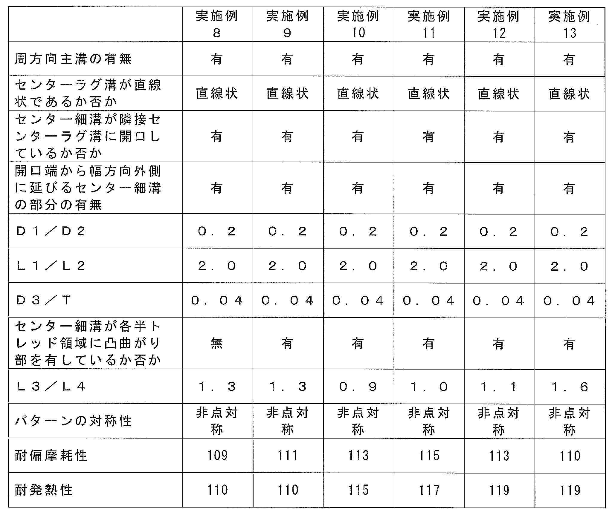
また、比L3/L4が1.0以上1.4以下である場合(実施例11および12)は、比L3/L4が1.4を超える場合(実施例13)と比べ、耐偏摩耗性に優れるとともに、耐発熱性および耐偏摩耗性のバランスに優れていた。 As can be seen from Tables 2 and 3, when the ratio D3 / T is 0.05 or less (Example 8), compared to the above ratio D3 / T exceeding 0.05 (Example 7), uneven wear resistance Greatly improved. Further, when the center narrow groove has a convex bent portion in each half-tread region (Example 9), the center thin groove does not have a convex bent portion in each half-tread region (Example) Compared to 8), uneven wear resistance was improved. In addition, the aspect which has a convex bending part only in one half-tread area | region was employ | adopted as an aspect which does not have a convex bending part in each half-tread area | region.
Further, when the ratio L3 / L4 is 1.0 or more and 1.4 or less (Examples 11 and 12), compared to the case where the ratio L3 / L4 exceeds 1.4 (Example 13), uneven wear resistance is achieved. And a good balance between heat resistance and uneven wear resistance.

表5~10に示されるようにトレッドパターンの異なる第2の態様のタイヤを種々試作し(実施例101~124、比較例101および102)、トレッドセンター領域の耐発熱性と、耐偏摩耗性とを調べた。タイヤは、図8に示すトレッドパターンに基いて、表5~10に示した仕様に沿って作製した。
試作したタイヤのサイズは実験1における第1の態様のタイヤと同じサイズである。評価についても、実験1と同じ試験条件で同じ耐発熱性試験及び耐偏摩耗試験を行なった。 この場合、耐発熱性および耐偏摩耗性の指数がいずれも100以上であって、かつ、指数の合計が206以上である場合を、耐発熱性および耐偏摩耗性を両立することができたと評価した。
なお、表5~10において、比「Dm/(BdまたはL11)」は、上述した、BdおよびL11のいずれか短い方に対するDmの比を表す。 (Experiment 2: tire of the second aspect)
As shown in Tables 5 to 10, various types of tires of the second aspect having different tread patterns were prototyped (Examples 101 to 124, Comparative Examples 101 and 102), and the heat resistance and uneven wear resistance of the tread center region were measured. And investigated. Tires were produced according to the specifications shown in Tables 5 to 10 based on the tread pattern shown in FIG.
The size of the prototyped tire is the same size as the tire of the first aspect in Experiment 1. Regarding the evaluation, the same heat generation resistance test and uneven wear resistance test were performed under the same test conditions as in Experiment 1. In this case, when both the heat generation resistance and uneven wear resistance indexes were 100 or more and the total of the indexes was 206 or more, both heat generation resistance and uneven wear resistance could be achieved. evaluated.
In Tables 5 to 10, the ratio “Dm / (Bd or L11)” represents the ratio of Dm to the shorter of Bd and L11 described above.

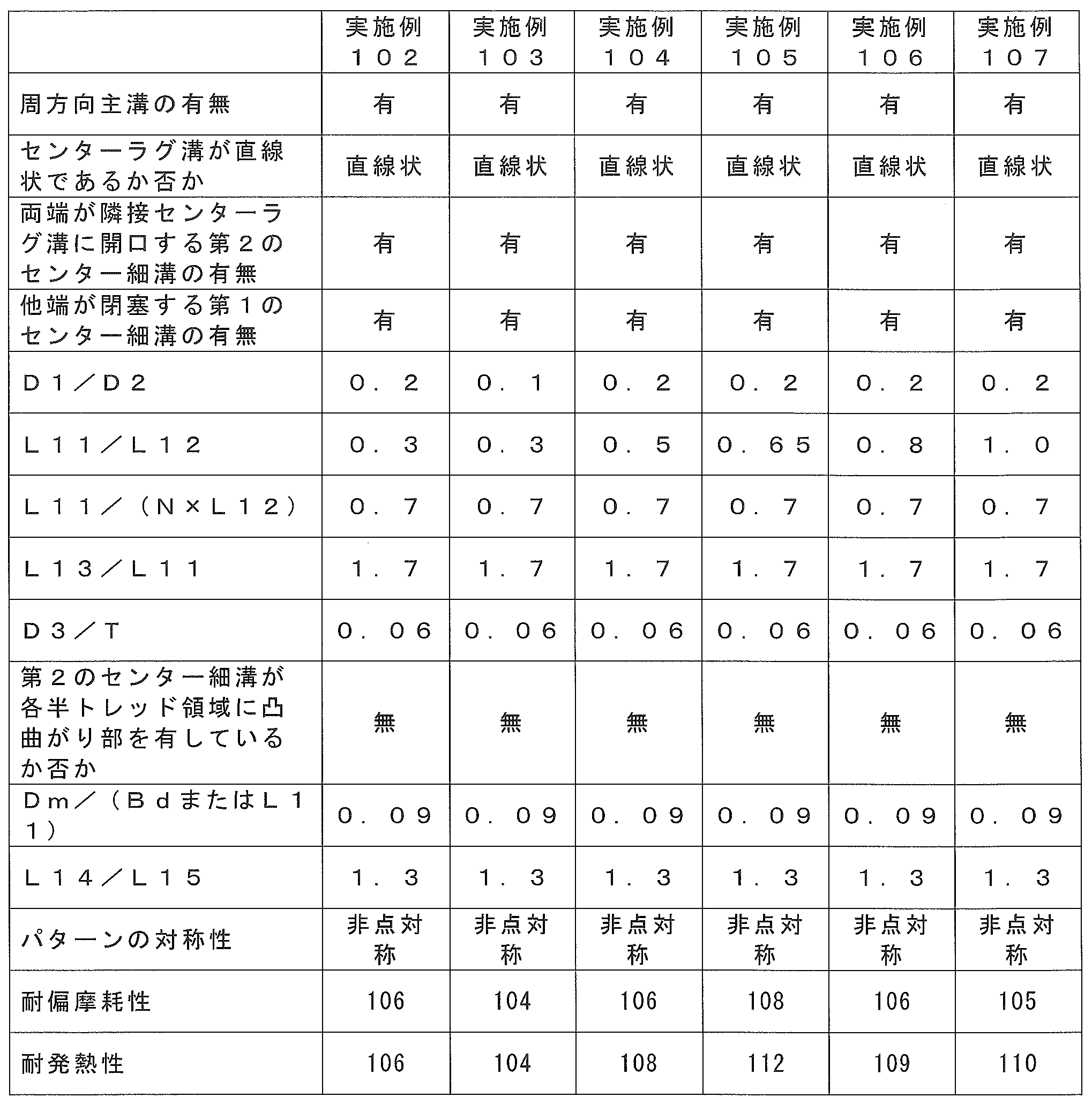
また、表6にからわかるように、比L11/L12が0.4以上0.9以下である場合(実施例104~106)は、比L11/L12が0.4未満である場合(実施例102)と比べ、耐偏摩耗性は少なくとも維持され、耐発熱性は向上した。また、比L11/L12が0.9を超える場合(実施例107)と比べ、耐偏摩耗性が向上した。 As can be seen from Tables 5 and 6, when the ratio D1 / D2 is 0.05 or more and 0.2 or less (Examples 102 and 103), D1 / D2 exceeds 0.2 (Example 101). Compared with, the uneven wear resistance was improved and the heat resistance was at least maintained.
As can be seen from Table 6, when the ratio L11 / L12 is 0.4 or more and 0.9 or less (Examples 104 to 106), the ratio L11 / L12 is less than 0.4 (Examples). Compared to 102), the partial wear resistance was maintained at least, and the heat resistance was improved. Moreover, compared with the case where the ratio L11 / L12 exceeds 0.9 (Example 107), the uneven wear resistance was improved.

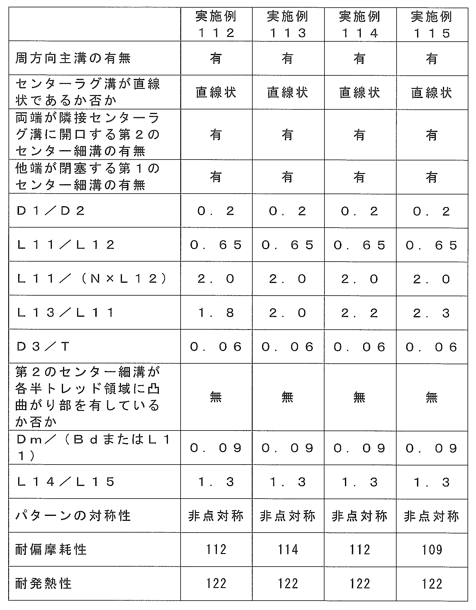
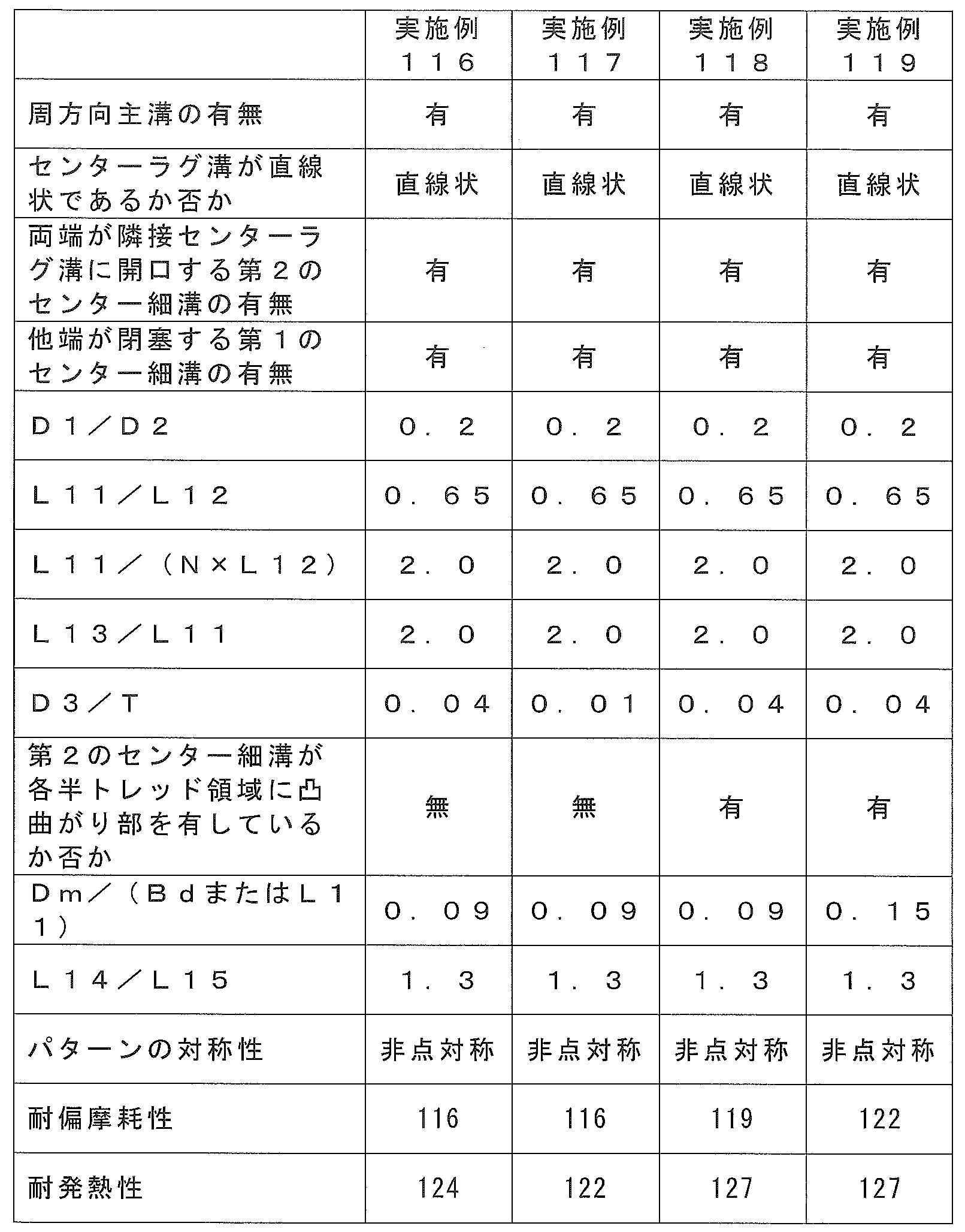
また、表9からわかるように、第2のセンター細溝が、各半トレッド領域に凸曲がり部を有している場合(実施例118)は、第2のセンター細溝が、各半トレッド領域に凸曲がり部を有していない場合(実施例116)と比べ、耐発熱性および耐偏摩耗性はいずれも向上した。なお、各半トレッド領域に凸曲がり部を有しない態様として、一方の半トレッド領域にのみ凸曲がり部を有する態様を採用した。
比Dm/(BdまたはL11)が0.1以上である場合(実施例119)は、比Dm/(BdまたはL11)が0.1未満である場合(実施例118)と比べ、耐偏摩耗性が向上した。なお、実施例118および119において、BdがL11よりも短いとし、比Dm/(BdまたはL11)として比Dm/L11を用いた。 As can be seen from Table 8 and Table 9, when D3 / T is 0.01 or more and 0.05 or less (Examples 116 and 117), when D3 / T exceeds 0.05 (Example 113). In comparison, the partial wear resistance was improved and the heat resistance was at least maintained.
Further, as can be seen from Table 9, when the second center narrow groove has a convex bent portion in each half-tread region (Example 118), the second center narrow groove has each half-tread region. As compared with the case where no convex bent part was provided (Example 116), both heat resistance and uneven wear resistance were improved. In addition, the aspect which has a convex bending part only in one half-tread area | region was employ | adopted as an aspect which does not have a convex bending part in each half-tread area | region.
When the ratio Dm / (Bd or L11) is 0.1 or more (Example 119), uneven wear resistance is higher than when the ratio Dm / (Bd or L11) is less than 0.1 (Example 118). Improved. In Examples 118 and 119, Bd was shorter than L11, and the ratio Dm / L11 was used as the ratio Dm / (Bd or L11).
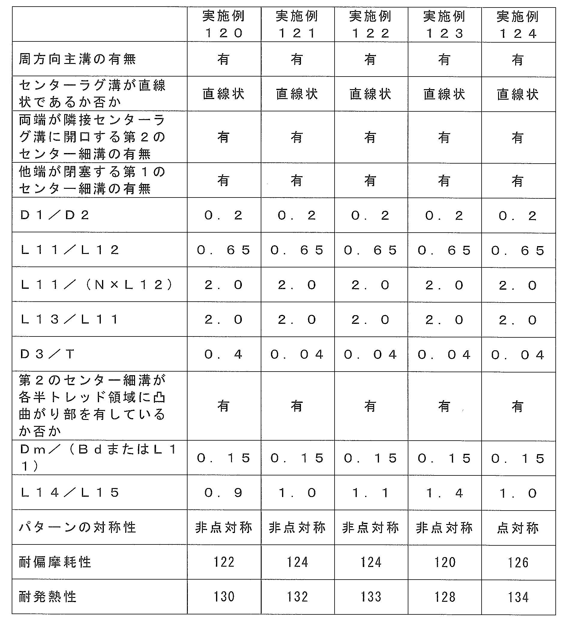
また、トレッドパターン10が点対称である場合(実施例124)は、点対称でない場合(実施例122)と比べ、耐発熱性および耐偏摩耗性はいずれも向上した。なお、なお、トレッドパターンが点対称でない態様として、両半トレッド領域のパターンが互いに異なっている態様を採用した。 As can be seen from Table 10, when the ratio L14 / L15 is 1.0 or more and 1.2 or less (Examples 121 to 122), the ratio L14 / L15 is less than 1.0 (Example 120). And compared with the case where ratio L14 / L15 exceeds 1.2 (Example 123), both heat resistance and uneven wear resistance were improved.
Further, when the
4 ベルト
6 トレッドゴム
10 トレッドパターン
11 センターラグ溝
13 ショルダーラグ溝
15 周方向主溝
15a 第1溝曲がり部
15b 第2溝曲がり部
15c 底上げ部
17 センター細溝(第2のセンター細溝)
17c、17d 開口端からタイヤ幅方向の外側に延びるセンター細溝の部分
18a,18b 凸曲がり部
19 ショルダー細溝
20 第1のセンター細溝
23 センターブロック
27 ショルダーブロック 1 Pneumatic tire for
17c, 17d Center
Claims (21)
- トレッドパターン付き重荷重用空気入りタイヤであって、
前記トレッドパターンは、
タイヤ周方向に間隔をあけて複数設けられ、タイヤ赤道線を横切るようにタイヤ赤道線を基準としたタイヤ幅方向の第1の側および第2の側の半トレッド領域に、タイヤ幅方向及びタイヤ周方向に対して傾斜した向きに延びて両端を有する直線形状のセンターラグ溝と、
前記半トレッド領域のそれぞれにおいて、タイヤ周方向に間隔をあけて複数設けられ、タイヤ幅方向外側に延びて、タイヤ幅方向外側の端がタイヤ幅方向の両側にある接地端に開口するショルダーラグ溝であって、前記ショルダーラグ溝のタイヤ幅方向内側の端のタイヤ幅方向の位置が、前記センターラグ溝の端のタイヤ幅方向の位置よりも外側にあり、かつ、タイヤ周方向において、前記センターラグ溝のうちタイヤ周方向に隣りあう隣接センターラグ溝の間に1つずつ設けられたショルダーラグ溝と、
前記半トレッド領域のそれぞれに設けられ、前記センターラグ溝の端と、前記ショルダーラグ溝のタイヤ幅方向の内側の端を交互に接続するように、タイヤ幅方向の外側に凸形状を成して湾曲あるいは屈曲した第1溝曲がり部とタイヤ幅方向の内側に凸形状を成して湾曲あるいは屈曲した第2溝曲がり部とが配置され、タイヤ周方向にわたって波形状に形成された一対の周方向主溝と、
前記隣接センターラグ溝と前記一対の周方向主溝によって画されてタイヤ周方向に一列に複数形成されたセンターブロックと、
前記センターブロックの領域を延びて、タイヤ赤道線上を除くタイヤ幅方向位置で前記隣接センターラグ溝のそれぞれに開口する開口端を有し、前記ショルダーラグ溝の溝幅より溝幅が狭く、直線形状でないセンター細溝と、
を備え、
前記センターラグ溝および前記周方向主溝の溝幅は、前記ショルダーラグ溝の溝幅より狭く、
前記センター細溝は、前記開口端が位置する前記半トレッド領域において、当該開口端からタイヤ幅方向外側に延びる部分を有している、ことを特徴とする重荷重用空気入りタイヤ。 A heavy duty pneumatic tire with a tread pattern,
The tread pattern is
A plurality of tire circumferential directions are provided at intervals in the tire circumferential direction, and the tire width direction and the tire are arranged in a half tread region on the first side and the second side in the tire width direction with respect to the tire equator line so as to cross the tire equator line. A linear center lug groove extending in a direction inclined with respect to the circumferential direction and having both ends;
In each of the half tread regions, a plurality of shoulder lug grooves that are provided at intervals in the tire circumferential direction, extend outward in the tire width direction, and open to the ground contact ends on both sides in the tire width direction. The position in the tire width direction of the end in the tire width direction of the shoulder lug groove is outside the position in the tire width direction of the end of the center lug groove, and in the tire circumferential direction, the center Shoulder lug grooves provided one by one between adjacent center lug grooves adjacent in the tire circumferential direction among the lug grooves;
Provided in each of the half-tread regions, and formed with a convex shape on the outer side in the tire width direction so as to alternately connect the end of the center lug groove and the inner end of the shoulder lug groove in the tire width direction. A pair of circumferential directions in which a curved or bent first groove bent portion and a curved or bent second groove bent portion inside the tire width direction are arranged and formed in a wave shape over the tire circumferential direction. The main groove,
Center blocks defined by the adjacent center lug grooves and the pair of circumferential main grooves and formed in a row in the tire circumferential direction;
Extending the area of the center block and having an opening end that opens to each of the adjacent center lug grooves at a position in the tire width direction excluding on the tire equator line, the groove width is narrower than the groove width of the shoulder lug groove, and has a linear shape Not a center narrow groove,
With
The groove width of the center lug groove and the circumferential main groove is narrower than that of the shoulder lug groove,
The center narrow groove has a portion extending outward in the tire width direction from the opening end in the half-tread region where the opening end is located. - 前記センター細溝の溝長さをL1とし、前記センターブロックのタイヤ周方向長さをL2としたとき、比L1/L2は1.8を超え2.2以下である、請求項1に記載の重荷重用空気入りタイヤ。 The ratio L1 / L2 is more than 1.8 and not more than 2.2 when the groove length of the center narrow groove is L1 and the tire circumferential length of the center block is L2. Heavy duty pneumatic tire.
- 前記センター細溝は、前記半トレッド領域のそれぞれに、タイヤ赤道線に対してタイヤ幅方向外側に突出するように延びる凸曲がり部を1つ有している、請求項1または2に記載の重荷重用空気入りタイヤ。 3. The heavy load according to claim 1, wherein the center narrow groove has one convex bent portion extending so as to protrude outward in the tire width direction with respect to the tire equator line in each of the half tread regions. Heavy duty pneumatic tire.
- 前記開口端から、前記凸曲がり部の頂部まで延びる前記センター細溝の部分の長さをLaとし、前記凸曲がり部の前記頂部同士の間を延びる前記センター細溝の部分の長さをLbとしたとき、LbはLaより長い、請求項3に記載の重荷重用空気入りタイヤ。 The length of the center narrow groove extending from the opening end to the top of the convex bent portion is La, and the length of the center narrow groove extending between the tops of the convex bent portion is Lb. The heavy duty pneumatic tire according to claim 3, wherein Lb is longer than La.
- 前記トレッドパターンは、さらに、
前記半トレッド領域のそれぞれにおいて、前記ショルダーラグ溝のうちタイヤ周方向に隣り合う一対の隣接ショルダーラグ溝、前記周方向主溝、および前記トレッド部のタイヤ幅方向の端によって画されてタイヤ周方向に一列に複数形成されたショルダーブロックと、 前記ショルダーブロックの領域を延びて、前記隣接ショルダーラグ溝のそれぞれに開口する、前記ショルダーラグ溝の溝幅より溝幅が狭いショルダー細溝と、を含む、請求項1から4のいずれか1項に記載の重荷重用空気入りタイヤ。 The tread pattern further includes
In each of the half tread regions, a tire circumferential direction defined by a pair of adjacent shoulder lug grooves adjacent to each other in the tire circumferential direction, the circumferential main grooves, and the tread portion in the tire width direction among the shoulder lug grooves. A plurality of shoulder blocks formed in a row, and a shoulder narrow groove that extends in the shoulder block region and opens in each of the adjacent shoulder lug grooves and has a narrower groove width than the shoulder lug groove width. The heavy-duty pneumatic tire according to any one of claims 1 to 4. - 前記ショルダー細溝の長さをL3とし、前記ショルダーブロックのタイヤ周方向の最小長さをL4としたとき、比L3/L4は1.0以上1.4以下である、請求項5に記載の重荷重用空気入りタイヤ。 The ratio L3 / L4 is 1.0 or more and 1.4 or less, when the length of the shoulder narrow groove is L3 and the minimum length in the tire circumferential direction of the shoulder block is L4. Heavy duty pneumatic tire.
- トレッドパターン付き重荷重用空気入りタイヤであって、
前記トレッドパターンは、
タイヤ周方向に間隔をあけて複数設けられ、タイヤ赤道線を横切るようにタイヤ赤道線を基準としたタイヤ幅方向の第1の側および第2の側の半トレッド領域に、タイヤ幅方向及びタイヤ周方向に対して傾斜した向きに延びて両端を有する直線形状のセンターラグ溝と、
前記半トレッド領域のそれぞれにおいて、タイヤ周方向に間隔をあけて複数設けられ、タイヤ幅方向外側に延びて、タイヤ幅方向外側の端がタイヤ幅方向の両側にある接地端に開口するショルダーラグ溝であって、前記ショルダーラグ溝のタイヤ幅方向内側の端のタイヤ幅方向の位置が、前記センターラグ溝の端のタイヤ幅方向の位置よりも外側にあり、かつ、タイヤ周方向において、前記センターラグ溝のうちタイヤ周方向に隣りあう隣接センターラグ溝の間に1つずつ設けられたショルダーラグ溝と、
前記半トレッド領域のそれぞれに設けられ、前記センターラグ溝の端と、前記ショルダーラグ溝のタイヤ幅方向の内側の端を交互に接続するように、タイヤ幅方向の外側に凸形状を成して湾曲あるいは屈曲した第1溝曲がり部とタイヤ幅方向の内側に凸形状を成して湾曲あるいは屈曲した第2溝曲がり部とが配置され、タイヤ周方向にわたって波形状に形成された一対の周方向主溝と、
前記隣接センターラグ溝と前記一対の周方向主溝によって画されてタイヤ周方向に一列に複数形成されたセンターブロックと、
前記センターブロックの領域を延びて、一方の端が前記周方向主溝および前記センターラグ溝のいずれかに開口し、他方の端が前記センターブロック内で閉塞する、前記ショルダーラグ溝の溝幅より溝幅が狭い1つまたは複数の第1のセンター細溝と、
前記センターブロックの領域を延びて、前記隣接センターラグ溝のそれぞれに開口し、前記ショルダーラグ溝の溝幅より溝幅が狭い第2のセンター細溝と、
を備え、
前記センターラグ溝および前記周方向主溝の溝幅は、前記ショルダーラグ溝の溝幅より狭いことを特徴とする重荷重用空気入りタイヤ。 A heavy duty pneumatic tire with a tread pattern,
The tread pattern is
A plurality of tire circumferential directions are provided at intervals in the tire circumferential direction, and the tire width direction and the tire are arranged in a half tread region on the first side and the second side in the tire width direction with respect to the tire equator line so as to cross the tire equator line. A linear center lug groove extending in a direction inclined with respect to the circumferential direction and having both ends;
In each of the half tread regions, a plurality of shoulder lug grooves that are provided at intervals in the tire circumferential direction, extend outward in the tire width direction, and open to the ground contact ends on both sides in the tire width direction. The position in the tire width direction of the end in the tire width direction of the shoulder lug groove is outside the position in the tire width direction of the end of the center lug groove, and in the tire circumferential direction, the center Shoulder lug grooves provided one by one between adjacent center lug grooves adjacent in the tire circumferential direction among the lug grooves;
Provided in each of the half-tread regions, and formed with a convex shape on the outer side in the tire width direction so as to alternately connect the end of the center lug groove and the inner end of the shoulder lug groove in the tire width direction. A pair of circumferential directions in which a curved or bent first groove bent portion and a curved or bent second groove bent portion inside the tire width direction are arranged and formed in a wave shape over the tire circumferential direction. The main groove,
Center blocks defined by the adjacent center lug grooves and the pair of circumferential main grooves and formed in a row in the tire circumferential direction;
From the groove width of the shoulder lug groove extending through the region of the center block, having one end opened in one of the circumferential main groove and the center lug groove and the other end closed in the center block. One or more first center narrow grooves having a narrow groove width;
Extending the region of the center block, opening to each of the adjacent center lug groove, a second center narrow groove having a groove width narrower than the groove width of the shoulder lug groove;
With
A heavy-duty pneumatic tire characterized in that a groove width of the center lug groove and the circumferential main groove is narrower than a width of the shoulder lug groove. - 前記センターブロックのタイヤ周方向長さをL11とし、前記第1のセンター細溝の溝長さをL12としたとき、比L11/L12は0.4以上0.9以下である、請求項7に記載の重荷重用空気入りタイヤ。 The ratio L11 / L12 is not less than 0.4 and not more than 0.9, where L11 is the length in the tire circumferential direction of the center block and L12 is the length of the first center narrow groove. The heavy-duty pneumatic tire described.
- 前記トレッドパターンは、複数の前記第1のセンター細溝として、溝長さがL12であるN本の前記第1のセンター細溝を含み、
前記センターブロックのタイヤ周方向長さをL11としたとき、比L11/(N×L12)は0.8以上3.0以下である、請求項7または8に記載の重荷重用空気入りタイヤ。 The tread pattern includes N first center narrow grooves having a groove length of L12 as the plurality of first center narrow grooves,
The heavy duty pneumatic tire according to claim 7 or 8, wherein a ratio L11 / (N x L12) is 0.8 or more and 3.0 or less, where L11 is a tire circumferential direction length of the center block. - 前記センターブロックのタイヤ周方向長さをL11とし、前記第2のセンター細溝の溝長さをL13としたとき、比L13/L11は1.8以上2.2以下である、請求項7~9のいずれか1項に記載の重荷重用空気入りタイヤ。 The ratio L13 / L11 is 1.8 or more and 2.2 or less, where L11 is the tire circumferential length of the center block and L13 is the groove length of the second center narrow groove. The heavy duty pneumatic tire according to any one of 9.
- 前記第2のセンター細溝は、前記半トレッド領域のそれぞれに、タイヤ赤道線に対してタイヤ幅方向外側に突出するように延びる凸曲がり部を1つ有している、請求項7から10のいずれか1項に記載の重荷重用空気入りタイヤ。 11. The second center narrow groove has one convex bent portion extending so as to protrude outward in the tire width direction with respect to the tire equator line in each of the half tread regions. The heavy duty pneumatic tire according to any one of the preceding claims.
- 前記センターブロック内における前記第1のセンター細溝と前記第2のセンター細溝との最短距離をDmとし、前記センターブロックのタイヤ周方向長さをL11とし、さらに、タイヤ周方向にわたって前記センターブロックおよび前記センターラグ溝の各領域の少なくとも一方だけが占めるタイヤ幅方向領域の長さをBdとしたとき、L11およびBdのいずれか短い方に対するDmの比は、0.1以上である、請求項7から11のいずれか1項に記載の重荷重用空気入りタイヤ。 The shortest distance between the first center narrow groove and the second center narrow groove in the center block is Dm, the center circumferential length of the center block is L11, and the center block extends in the tire circumferential direction. The ratio of Dm to L11 or Bd, whichever is shorter, is 0.1 or more, where Bd is the length of the tire width direction region occupied by at least one of the regions of the center lug groove. The heavy duty pneumatic tire according to any one of 7 to 11.
- 前記トレッドパターンは、さらに、
前記半トレッド領域のそれぞれにおいて、前記ショルダーラグ溝のうちタイヤ周方向に隣り合う一対の隣接ショルダーラグ溝、前記周方向主溝、および前記トレッド部のタイヤ幅方向の端によって画されてタイヤ周方向に一列に複数形成されたショルダーブロックと、 前記ショルダーブロックの領域を延びて、前記隣接ショルダーラグ溝のそれぞれに開口し、前記ショルダーラグ溝の溝幅より溝幅が狭いショルダー細溝と、を含む、請求項7から12のいずれか1項に記載の重荷重用空気入りタイヤ。 The tread pattern further includes
In each of the half tread regions, a tire circumferential direction defined by a pair of adjacent shoulder lug grooves adjacent to each other in the tire circumferential direction, the circumferential main grooves, and the tread portion in the tire width direction among the shoulder lug grooves. A plurality of shoulder blocks formed in a row, and a shoulder narrow groove extending in the shoulder block region and opening in each of the adjacent shoulder lug grooves, and having a groove width narrower than the groove width of the shoulder lug grooves. The heavy-duty pneumatic tire according to any one of claims 7 to 12. - 前記ショルダー細溝の長さをL14とし、前記ショルダーブロックのタイヤ周方向の最小長さをL15としたとき、比L14/L15は1.0以上1.2以下である、請求項13に記載の重荷重用空気入りタイヤ。 The ratio L14 / L15 is 1.0 or more and 1.2 or less, where L14 is the length of the shoulder narrow groove and L15 is the minimum length of the shoulder block in the tire circumferential direction. Heavy duty pneumatic tire.
-
前記周方向主溝の最大溝深さは、前記センターラグ溝の最大溝深さよりも浅く、前記センターラグ溝の最大溝深さは、前記ショルダーラグ溝の最大溝深さよりも浅い、請求項1から14のいずれか1項に記載の重荷重用空気入りタイヤ。
The maximum groove depth of the circumferential main groove is shallower than the maximum groove depth of the center lug groove, and the maximum groove depth of the center lug groove is shallower than the maximum groove depth of the shoulder lug groove. The heavy-duty pneumatic tire according to any one of 1 to 14. -
前記センター細溝、あるいは、前記第1のセンター細溝および前記第2のセンター細溝の最大溝深さをD1とし、前記周方向主溝の最大溝深さをD2としたとき、比D1/D2は0.05以上0.2以下である、請求項1から15のいずれか1項に記載の重荷重用空気入りタイヤ。
When the maximum groove depth of the center narrow groove or the first center thin groove and the second center narrow groove is D1, and the maximum groove depth of the circumferential main groove is D2, the ratio D1 / The heavy duty pneumatic tire according to any one of claims 1 to 15, wherein D2 is 0.05 or more and 0.2 or less. -
前記一対の周方向主溝のそれぞれにおいて、溝深さが部分的に浅くなった底上げ部を備える、請求項1から16のいずれか1項に記載の重荷重用空気入りタイヤ。
The heavy-duty pneumatic tire according to any one of claims 1 to 16, further comprising a bottom raised portion in which the groove depth is partially shallow in each of the pair of circumferential main grooves. - 前記底上げ部において最も浅い溝深さをD3とし、前記トレッド部のタイヤ幅方向のトレッド幅をTとしたとき、比D3/Tは0.01以上0.05以下である、請求項17に記載の重荷重用空気入りタイヤ。 The ratio D3 / T is 0.01 or more and 0.05 or less, where D3 is the shallowest groove depth in the raised portion and T is the tread width in the tire width direction of the tread portion. Heavy duty pneumatic tires.
- 前記トレッドパターンは、前記センターブロックのトレッド表面における中心点を基準として点対称である、請求項1から18のいずれか1項に記載の重荷重用空気入りタイヤ。 The heavy-duty pneumatic tire according to any one of claims 1 to 18, wherein the tread pattern is point-symmetric with respect to a center point on a tread surface of the center block.
- 前記周方向主溝および前記センターラグ溝の溝幅はそれぞれ7mm以上20mm以下である、請求項1から19のいずれか1項に記載の重荷重用空気入りタイヤ。 The heavy duty pneumatic tire according to any one of claims 1 to 19, wherein each of the circumferential main grooves and the center lug grooves has a groove width of 7 mm or more and 20 mm or less.
- 建設用車両または産業用車両に装着される、請求項1から20のいずれか1項に記載の重荷重用空気入りタイヤ。
The heavy-duty pneumatic tire according to any one of claims 1 to 20, which is mounted on a construction vehicle or an industrial vehicle.
Priority Applications (4)
| Application Number | Priority Date | Filing Date | Title |
|---|---|---|---|
| US16/090,158 US11312187B2 (en) | 2016-03-31 | 2017-03-28 | Heavy-duty pneumatic tire |
| AU2017241709A AU2017241709B2 (en) | 2016-03-31 | 2017-03-28 | Heavy-duty pneumatic tire |
| RU2018138159A RU2708539C1 (en) | 2016-03-31 | 2017-03-28 | Pneumatic tire for high-load machines |
| CN201780021507.7A CN109070644B (en) | 2016-03-31 | 2017-03-28 | Heavy duty pneumatic tire |
Applications Claiming Priority (4)
| Application Number | Priority Date | Filing Date | Title |
|---|---|---|---|
| JP2016-072182 | 2016-03-31 | ||
| JP2016-072149 | 2016-03-31 | ||
| JP2016072149A JP6443376B2 (en) | 2016-03-31 | 2016-03-31 | Heavy duty pneumatic tire |
| JP2016072182A JP6237810B2 (en) | 2016-03-31 | 2016-03-31 | Heavy duty pneumatic tire |
Publications (1)
| Publication Number | Publication Date |
|---|---|
| WO2017170562A1 true WO2017170562A1 (en) | 2017-10-05 |
Family
ID=59964655
Family Applications (1)
| Application Number | Title | Priority Date | Filing Date |
|---|---|---|---|
| PCT/JP2017/012665 WO2017170562A1 (en) | 2016-03-31 | 2017-03-28 | Heavy-duty pneumatic tire |
Country Status (5)
| Country | Link |
|---|---|
| US (1) | US11312187B2 (en) |
| CN (1) | CN109070644B (en) |
| AU (1) | AU2017241709B2 (en) |
| RU (1) | RU2708539C1 (en) |
| WO (1) | WO2017170562A1 (en) |
Cited By (4)
| Publication number | Priority date | Publication date | Assignee | Title |
|---|---|---|---|---|
| WO2019142509A1 (en) * | 2018-01-18 | 2019-07-25 | 横浜ゴム株式会社 | Pneumatic tire |
| EP3666552A1 (en) * | 2018-12-13 | 2020-06-17 | Sumitomo Rubber Industries, Ltd. | Tyre |
| US20210331525A1 (en) * | 2020-04-28 | 2021-10-28 | The Yokohama Rubber Co., Ltd. | Tire |
| US11724549B2 (en) | 2018-01-18 | 2023-08-15 | The Yokohama Rubber Co., Ltd. | Pneumatic tire |
Families Citing this family (1)
| Publication number | Priority date | Publication date | Assignee | Title |
|---|---|---|---|---|
| CN115431679B (en) * | 2022-07-01 | 2023-11-28 | 厦门正新橡胶工业有限公司 | Tread pattern structure of pneumatic tire and pneumatic tire |
Citations (7)
| Publication number | Priority date | Publication date | Assignee | Title |
|---|---|---|---|---|
| JPH0958220A (en) * | 1995-08-29 | 1997-03-04 | Bridgestone Corp | Pneumatic tire with block pattern |
| JP2000177326A (en) * | 1998-12-21 | 2000-06-27 | Sumitomo Rubber Ind Ltd | Heavy load tire |
| WO2002100664A1 (en) * | 2001-06-07 | 2002-12-19 | Bridgestone Corporation | Off-the-road tire |
| JP2004203268A (en) * | 2002-12-26 | 2004-07-22 | Bridgestone Corp | Radial tire |
| WO2006001202A1 (en) * | 2004-06-23 | 2006-01-05 | Bridgestone Corporation | Pneumatic tire |
| JP2008279976A (en) * | 2007-05-14 | 2008-11-20 | Bridgestone Corp | Heavy duty pneumatic radial tire for construction vehicle |
| WO2016013604A1 (en) * | 2014-07-23 | 2016-01-28 | 横浜ゴム株式会社 | Heavy duty pneumatic tire |
Family Cites Families (13)
| Publication number | Priority date | Publication date | Assignee | Title |
|---|---|---|---|---|
| JPS5470503A (en) | 1977-11-17 | 1979-06-06 | Bridgestone Corp | Air-inflated tire for heavy load |
| JP3833785B2 (en) * | 1997-07-15 | 2006-10-18 | 株式会社ブリヂストン | Pneumatic tire |
| JP4000214B2 (en) * | 1998-02-06 | 2007-10-31 | 株式会社ブリヂストン | Heavy duty pneumatic radial tires |
| JP2000177328A (en) * | 1998-12-18 | 2000-06-27 | Bridgestone Corp | Heavy load pneumatic tire |
| JP4358572B2 (en) * | 2002-07-31 | 2009-11-04 | 株式会社ブリヂストン | Off-the-road tires |
| JP2004262295A (en) * | 2003-02-28 | 2004-09-24 | Bridgestone Corp | Heavy duty pneumatic tire for construction vehicle |
| JP2008114738A (en) * | 2006-11-06 | 2008-05-22 | Bridgestone Corp | Tire for heavy load and usage thereof |
| JP5254760B2 (en) * | 2008-11-27 | 2013-08-07 | 株式会社ブリヂストン | tire |
| WO2011080565A1 (en) | 2009-12-28 | 2011-07-07 | Pirelli Tyre S.P.A. | Pneumatic tire for on road and off road use |
| JP5406949B2 (en) * | 2012-01-16 | 2014-02-05 | 住友ゴム工業株式会社 | Heavy duty pneumatic tire |
| WO2013157544A1 (en) * | 2012-04-16 | 2013-10-24 | 株式会社ブリヂストン | Tire |
| JP5695099B2 (en) | 2013-01-30 | 2015-04-01 | 株式会社ブリヂストン | Pneumatic tires for construction vehicles |
| JP5923057B2 (en) * | 2013-04-30 | 2016-05-24 | 住友ゴム工業株式会社 | Heavy duty tire |
-
2017
- 2017-03-28 CN CN201780021507.7A patent/CN109070644B/en active Active
- 2017-03-28 US US16/090,158 patent/US11312187B2/en active Active
- 2017-03-28 RU RU2018138159A patent/RU2708539C1/en active
- 2017-03-28 WO PCT/JP2017/012665 patent/WO2017170562A1/en active Application Filing
- 2017-03-28 AU AU2017241709A patent/AU2017241709B2/en active Active
Patent Citations (7)
| Publication number | Priority date | Publication date | Assignee | Title |
|---|---|---|---|---|
| JPH0958220A (en) * | 1995-08-29 | 1997-03-04 | Bridgestone Corp | Pneumatic tire with block pattern |
| JP2000177326A (en) * | 1998-12-21 | 2000-06-27 | Sumitomo Rubber Ind Ltd | Heavy load tire |
| WO2002100664A1 (en) * | 2001-06-07 | 2002-12-19 | Bridgestone Corporation | Off-the-road tire |
| JP2004203268A (en) * | 2002-12-26 | 2004-07-22 | Bridgestone Corp | Radial tire |
| WO2006001202A1 (en) * | 2004-06-23 | 2006-01-05 | Bridgestone Corporation | Pneumatic tire |
| JP2008279976A (en) * | 2007-05-14 | 2008-11-20 | Bridgestone Corp | Heavy duty pneumatic radial tire for construction vehicle |
| WO2016013604A1 (en) * | 2014-07-23 | 2016-01-28 | 横浜ゴム株式会社 | Heavy duty pneumatic tire |
Cited By (7)
| Publication number | Priority date | Publication date | Assignee | Title |
|---|---|---|---|---|
| WO2019142509A1 (en) * | 2018-01-18 | 2019-07-25 | 横浜ゴム株式会社 | Pneumatic tire |
| JP2019123448A (en) * | 2018-01-18 | 2019-07-25 | 横浜ゴム株式会社 | Pneumatic tire |
| JP6992533B2 (en) | 2018-01-18 | 2022-01-13 | 横浜ゴム株式会社 | Pneumatic tires |
| US11724549B2 (en) | 2018-01-18 | 2023-08-15 | The Yokohama Rubber Co., Ltd. | Pneumatic tire |
| EP3666552A1 (en) * | 2018-12-13 | 2020-06-17 | Sumitomo Rubber Industries, Ltd. | Tyre |
| US11820175B2 (en) | 2018-12-13 | 2023-11-21 | Sumitomo Rubber Industries, Ltd. | Tyre |
| US20210331525A1 (en) * | 2020-04-28 | 2021-10-28 | The Yokohama Rubber Co., Ltd. | Tire |
Also Published As
| Publication number | Publication date |
|---|---|
| RU2708539C1 (en) | 2019-12-09 |
| AU2017241709B2 (en) | 2019-09-19 |
| US11312187B2 (en) | 2022-04-26 |
| AU2017241709A1 (en) | 2018-11-08 |
| CN109070644B (en) | 2021-02-09 |
| US20190111737A1 (en) | 2019-04-18 |
| CN109070644A (en) | 2018-12-21 |
Similar Documents
| Publication | Publication Date | Title |
|---|---|---|
| WO2017170562A1 (en) | Heavy-duty pneumatic tire | |
| CN106536225B (en) | Heavy duty pneumatic vehicle tire | |
| WO2016013600A1 (en) | Heavy duty pneumatic tire | |
| JP6237970B1 (en) | Heavy duty pneumatic tire | |
| JP6237971B1 (en) | Heavy duty pneumatic tire | |
| AU2015331554B2 (en) | Pneumatic tire | |
| JP6237810B2 (en) | Heavy duty pneumatic tire | |
| JP6443376B2 (en) | Heavy duty pneumatic tire | |
| JP6229723B2 (en) | Heavy duty pneumatic tire | |
| JP5910795B1 (en) | Heavy duty pneumatic tire | |
| JP6565996B2 (en) | Pneumatic tire | |
| WO2021117659A1 (en) | Tire |
Legal Events
| Date | Code | Title | Description |
|---|---|---|---|
| NENP | Non-entry into the national phase |
Ref country code: DE |
|
| ENP | Entry into the national phase |
Ref document number: 2017241709 Country of ref document: AU Date of ref document: 20170328 Kind code of ref document: A |
|
| 121 | Ep: the epo has been informed by wipo that ep was designated in this application |
Ref document number: 17775099 Country of ref document: EP Kind code of ref document: A1 |
|
| 122 | Ep: pct application non-entry in european phase |
Ref document number: 17775099 Country of ref document: EP Kind code of ref document: A1 |