WO2017170085A1 - 医用診断装置、及び医用診断プログラム - Google Patents
医用診断装置、及び医用診断プログラム Download PDFInfo
- Publication number
- WO2017170085A1 WO2017170085A1 PCT/JP2017/011603 JP2017011603W WO2017170085A1 WO 2017170085 A1 WO2017170085 A1 WO 2017170085A1 JP 2017011603 W JP2017011603 W JP 2017011603W WO 2017170085 A1 WO2017170085 A1 WO 2017170085A1
- Authority
- WO
- WIPO (PCT)
- Prior art keywords
- image
- image data
- medical
- ultrasonic
- instruction signal
- Prior art date
- Legal status (The legal status is an assumption and is not a legal conclusion. Google has not performed a legal analysis and makes no representation as to the accuracy of the status listed.)
- Ceased
Links
Images




Classifications
-
- A—HUMAN NECESSITIES
- A61—MEDICAL OR VETERINARY SCIENCE; HYGIENE
- A61B—DIAGNOSIS; SURGERY; IDENTIFICATION
- A61B8/00—Diagnosis using ultrasonic, sonic or infrasonic waves
- A61B8/46—Ultrasonic, sonic or infrasonic diagnostic devices with special arrangements for interfacing with the operator or the patient
- A61B8/461—Displaying means of special interest
- A61B8/463—Displaying means of special interest characterised by displaying multiple images or images and diagnostic data on one display
-
- A—HUMAN NECESSITIES
- A61—MEDICAL OR VETERINARY SCIENCE; HYGIENE
- A61B—DIAGNOSIS; SURGERY; IDENTIFICATION
- A61B8/00—Diagnosis using ultrasonic, sonic or infrasonic waves
- A61B8/48—Diagnostic techniques
- A61B8/488—Diagnostic techniques involving Doppler signals
-
- A—HUMAN NECESSITIES
- A61—MEDICAL OR VETERINARY SCIENCE; HYGIENE
- A61B—DIAGNOSIS; SURGERY; IDENTIFICATION
- A61B8/00—Diagnosis using ultrasonic, sonic or infrasonic waves
- A61B8/56—Details of data transmission or power supply
- A61B8/565—Details of data transmission or power supply involving data transmission via a network
-
- G—PHYSICS
- G16—INFORMATION AND COMMUNICATION TECHNOLOGY [ICT] SPECIALLY ADAPTED FOR SPECIFIC APPLICATION FIELDS
- G16H—HEALTHCARE INFORMATICS, i.e. INFORMATION AND COMMUNICATION TECHNOLOGY [ICT] SPECIALLY ADAPTED FOR THE HANDLING OR PROCESSING OF MEDICAL OR HEALTHCARE DATA
- G16H30/00—ICT specially adapted for the handling or processing of medical images
- G16H30/20—ICT specially adapted for the handling or processing of medical images for handling medical images, e.g. DICOM, HL7 or PACS
-
- G—PHYSICS
- G16—INFORMATION AND COMMUNICATION TECHNOLOGY [ICT] SPECIALLY ADAPTED FOR SPECIFIC APPLICATION FIELDS
- G16H—HEALTHCARE INFORMATICS, i.e. INFORMATION AND COMMUNICATION TECHNOLOGY [ICT] SPECIALLY ADAPTED FOR THE HANDLING OR PROCESSING OF MEDICAL OR HEALTHCARE DATA
- G16H40/00—ICT specially adapted for the management or administration of healthcare resources or facilities; ICT specially adapted for the management or operation of medical equipment or devices
- G16H40/60—ICT specially adapted for the management or administration of healthcare resources or facilities; ICT specially adapted for the management or operation of medical equipment or devices for the operation of medical equipment or devices
- G16H40/63—ICT specially adapted for the management or administration of healthcare resources or facilities; ICT specially adapted for the management or operation of medical equipment or devices for the operation of medical equipment or devices for local operation
-
- A—HUMAN NECESSITIES
- A61—MEDICAL OR VETERINARY SCIENCE; HYGIENE
- A61B—DIAGNOSIS; SURGERY; IDENTIFICATION
- A61B8/00—Diagnosis using ultrasonic, sonic or infrasonic waves
- A61B8/44—Constructional features of the ultrasonic, sonic or infrasonic diagnostic device
- A61B8/4444—Constructional features of the ultrasonic, sonic or infrasonic diagnostic device related to the probe
-
- G—PHYSICS
- G16—INFORMATION AND COMMUNICATION TECHNOLOGY [ICT] SPECIALLY ADAPTED FOR SPECIFIC APPLICATION FIELDS
- G16H—HEALTHCARE INFORMATICS, i.e. INFORMATION AND COMMUNICATION TECHNOLOGY [ICT] SPECIALLY ADAPTED FOR THE HANDLING OR PROCESSING OF MEDICAL OR HEALTHCARE DATA
- G16H10/00—ICT specially adapted for the handling or processing of patient-related medical or healthcare data
- G16H10/60—ICT specially adapted for the handling or processing of patient-related medical or healthcare data for patient-specific data, e.g. for electronic patient records
-
- G—PHYSICS
- G16—INFORMATION AND COMMUNICATION TECHNOLOGY [ICT] SPECIALLY ADAPTED FOR SPECIFIC APPLICATION FIELDS
- G16H—HEALTHCARE INFORMATICS, i.e. INFORMATION AND COMMUNICATION TECHNOLOGY [ICT] SPECIALLY ADAPTED FOR THE HANDLING OR PROCESSING OF MEDICAL OR HEALTHCARE DATA
- G16H30/00—ICT specially adapted for the handling or processing of medical images
- G16H30/40—ICT specially adapted for the handling or processing of medical images for processing medical images, e.g. editing
Definitions
- the present invention relates to a medical diagnostic apparatus and a medical diagnostic program.
- a medical image management system (PACS: Picture Archiving Communication System) that displays the ultrasonic image on a viewer screen of a terminal device (PACS client) for image display and is used for interpretation diagnosis by a doctor or the like is known.
- a doctor or the like When a patient to be diagnosed is imaged by modality, a doctor or the like naturally makes a diagnosis while referring to the ultrasonic image on the viewer screen of the terminal device for image display.
- an ultrasonic image picked up by a modality is captured and stored / managed by a medical image management apparatus. Therefore, when referring to the ultrasonic image, a doctor or the like needs to search for and read out the target ultrasonic image from the medical image management apparatus, and the operation burden on the doctor or the like is large.
- Patent Document 1 when a program for a terminal device for image display and a program for a modality are linked, an image capture button provided in the terminal device for image display is pressed. It describes that ultrasonic image data is acquired from a modality and displayed on a viewer screen.
- Patent Document 1 an operator such as a doctor or an engineer (hereinafter referred to as “doctor” or the like) on the side of an image display terminal device (hereinafter referred to as “image display device”). It is assumed that the user operates on the viewer screen of the image display device in a sitting state, and instructs the modality to take an image and to take in the ultrasonic image data.
- FIG. 13 is a diagram illustrating an example of the above-described ultrasonic diagnostic system.
- 1 is an ultrasonic diagnostic apparatus
- 2 is an image display apparatus
- 5 is an electronic medical record management apparatus
- P1 is a doctor, etc.
- P2 is a patient.
- Patent Document 1 when the program of the image display device and the modality program are linked, it is necessary to set the association with the subject information such as the patient ID. Therefore, it is necessary to use subject information such as an electronic medical record in the case of a new patient, and to set new subject information in the case of a new patient. As a result, when doctors and the like frequently use the ultrasonic diagnostic apparatus, it has been a heavy burden.
- an object of the present invention is to provide a medical diagnostic apparatus and a medical diagnostic program that can reduce an operation burden on a doctor or the like when browsing a medical image on an image display apparatus.
- the main present invention that solves the above-described problems is a medical device configured to be able to communicate with an image display device that displays a medical image obtained by imaging a region to be examined of a subject, and an image management device that manages image data of the medical image.
- An identification unit that identifies the image data of the medical image to the image management device in accordance with an input unit that receives an operation input from an operator and a save instruction signal generated based on the operation input.
- the image data is stored in association with the identification information, and a display instruction signal for displaying the image data of the medical image together with the identification information is transmitted to the image display device.
- a control unit that obtains image data of the medical image from the image management apparatus.
- a medical diagnostic program executed by a medical diagnostic apparatus configured to be communicable with an image display apparatus that displays a medical image obtained by imaging a region to be examined of a subject and an image management apparatus that manages image data of the medical image.
- image data of the medical image is transmitted to the image management apparatus together with identification information. Storing the image data in association with the identification information, and transmitting a display instruction signal for displaying the image data of the medical image together with the identification information to the image display device; And a process for acquiring the image data from the image management apparatus.
- the medical diagnostic apparatus of the present invention it is possible to reduce an operation burden on a doctor or the like when browsing an ultrasonic image on the image display apparatus.
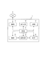
- FIG. 1 The figure which shows an example of the whole structure of the ultrasound diagnosing system which concerns on embodiment
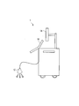
- the figure which shows the external appearance of the ultrasound diagnosing device which concerns on embodiment 2 is a diagram illustrating an example of functional blocks of an image display device according to an embodiment.
- FIG. 3 is a diagram illustrating an example of a detailed operation flow of the image management apparatus according to the embodiment.
- FIG. 1 is a diagram showing an example of the overall configuration of an ultrasonic diagnostic system.
- FIG. 2 is a diagram illustrating an example of functional blocks of the ultrasonic diagnostic apparatus.
- FIG. 3 is a diagram showing the appearance of the ultrasonic diagnostic apparatus.
- FIG. 4 is a diagram illustrating an example of functional blocks of the image display apparatus.
- the ultrasonic diagnostic system includes, for example, an ultrasonic diagnostic apparatus 1, an image display apparatus 2, an electronic medical record terminal 3, an image management apparatus 4, an electronic medical record management apparatus 5, and a communication line 6 ( (See FIG. 1).
- the ultrasonic diagnostic apparatus 1, the image display apparatus 2, and the electronic medical record terminal 3 are installed in a hospital examination room, and the image management apparatus 4 and the electronic medical record management apparatus 5 are installed in a server room. These devices are connected for communication via a communication line 6.
- the communication line 6 is, for example, a LAN (Local Area Network) line installed in a hospital, and these devices perform data communication in accordance with DICOM (Digital Imaging and Communication Communication in Medical) standards.
- DICOM Digital Imaging and Communication Communication in Medical
- the hospital is provided with a receipt terminal (not shown), and when the patient comes to the hospital, the receipt terminal receives the electronic medical record of the patient from the electronic medical record management apparatus 5. Then, the person in charge of the window confirms the contents of the electronic medical record on the display screen of the reception terminal, and transmits the electronic medical record from the reception terminal to the electronic medical record terminal 3.
- an ultrasonic diagnostic apparatus 1, an image display apparatus 2, and an electronic medical record terminal 3 are installed, and a doctor performs a diagnosis using the ultrasonic diagnostic apparatus 1, the image display apparatus 2, and the electronic medical record terminal 3.
- the electronic medical record terminal 3 stores the electronic medical records of a plurality of patients to be examined in the order in which the electronic medical records are received from the receipt terminal. As a result, the patient enters a waiting state for medical examination, and the electronic medical record terminal 3 displays the contents of the electronic medical chart of the next patient to be examined on the display screen when the doctor performs an operation for updating the patient to be examined.
- the doctor examines the patient to be examined and inputs the contents of the examination into the electronic medical record terminal 3.
- the doctor uses the ultrasonic diagnostic apparatus 1 as necessary to examine the patient.
- the ultrasonic diagnostic apparatus 1 stores image data including the acquired ultrasonic image in the image management apparatus 4.
- the image data stored in the image management device 4 is read by the image display device 2, and the ultrasonic image is displayed on the display screen of the image display device 2.
- the doctor uses the medical image displayed on the display screen of the image display device 2 to explain to the patient and inputs the findings to the electronic medical record terminal 3.
- the electronic medical chart terminal 3 transmits the electronic medical chart to the receipt terminal. Then, the doctor performs an operation for updating the patient to be examined and examines the next patient.
- the ultrasonic diagnostic apparatus 1 is an apparatus that displays and outputs an ultrasonic image of the state of the internal tissue of a subject (see FIGS. 2 and 3).
- a patient to be examined by the ultrasonic diagnostic apparatus 1 is referred to as “subject”, and data relating to the subject is also referred to as “subject information”.
- the ultrasonic diagnostic apparatus 1 generates a color Doppler image as an ultrasonic image, for example.
- a color Doppler image is superimposed on a B-mode image (Brightness mode Imaging) that represents a tomographic image in a living body in gray scale, and a color image (Color Flow Imaging) that expresses the movement of body tissues such as blood flow and myocardial wall in color. ) Is displayed.
- B-mode image Bitness mode Imaging
- Color Flow Imaging Color Flow Imaging
- the ultrasonic diagnostic apparatus 1 includes a control unit 11, an imaging unit 12, an image processing unit 13, a display unit 14, a communication unit 15, an operation input unit 16, and a storage unit 17 (see FIG. 2).
- the control unit 11 comprehensively controls the operation of each unit of the ultrasonic diagnostic apparatus 1.
- the control unit 11 is realized, for example, when the CPU executes a program.
- the imaging unit 12 captures an examination site of the subject and generates two-dimensional data that is a frame unit for generating an ultrasound image.
- the imaging unit 12 includes an ultrasonic probe including a plurality of transducers, and in the state where the ultrasonic probe is pressed against the abdomen of the subject, the ultrasonic beam is applied to the inside of the subject. Send.
- the ultrasonic probe receives the ultrasonic echo reflected in the subject and generates a reception signal.
- the imaging unit 12 accumulates the temporal change in the signal intensity of the reception signal generated by the ultrasonic echo in the line memory. Then, the imaging unit 12 scans a plurality of transducers of the ultrasonic probe, switches the direction in which the ultrasonic beam is transmitted and received, and sequentially accumulates the received signal at each scanning position in the line memory. As a result, two-dimensional data for each frame is generated.
- the B-mode image is generated by converting the signal intensity of the received signal related to the two-dimensional data into a luminance value. Further, when generating a color image, the imaging unit 12 detects an ultrasonic echo from the same depth position of a pulsed ultrasonic beam transmitted continuously. Then, the imaging unit 12 generates a blood flow signal by calculating the velocity, power, and dispersion of the blood flow existing at the depth position based on the phase difference between the continuous ultrasonic echoes. As with the B-mode image, the imaging unit 12 scans the ultrasound probe and switches the direction in which the ultrasound beam is transmitted and received, thereby sequentially transmitting the blood flow signal at each scanning position to the line memory. Accumulate and generate 2D data for each frame. The color image is generated by converting the velocity, power, and variance of the blood flow signal related to the two-dimensional data into RGB values.
- the image processing unit 13 acquires two-dimensional data in frame units from the imaging unit 12 and generates an ultrasonic image. Specifically, as described above, the image processing unit 13 generates a B-mode image from the two-dimensional data related to the signal strength of the received signal, and the color image from the two-dimensional data related to the velocity, power, and dispersion of the blood flow signal. Is generated. Then, the image processing unit 13 generates a color Doppler image by superimposing a moving color image on the B-mode image.
- the image processing unit 13 generates image data (hereinafter, also referred to as “ultrasonic image data”) obtained by adding an image indicating identification information of the subject to the ultrasonic image generated in this manner, and displays it on the display unit 14. It is displayed (described later with reference to FIG. 6).
- the image processing unit 13 includes a buffer memory for generating the above-described image and a large-capacity memory capable of holding image data of the generated image. Then, the image processing unit 13 encodes the image data in accordance with a save instruction from the control unit 11, sends the image data to the storage unit 17, and stores it as still image data or moving image data.
- the image processing unit 13 performs coordinate conversion processing or data interpolation processing on the ultrasonic image, converts the image data into image data that can be displayed on the display unit 14, and outputs the image data.
- the display unit 14 is a display device such as an LCD or a CRT display.
- the display unit 14 displays the ultrasonic image on the display screen based on the image data of the ultrasonic image generated by the image processing unit 13.
- the communication unit 15 is a communication interface for transmitting / receiving data to / from external devices such as the electronic medical record terminal 3, the image management device 4, and the electronic medical record management device 5 through the communication line 6, and is configured by a LAN adapter, for example. Is done.
- the operation input unit 16 (input unit) is, for example, a touch panel or an operation button, and receives an input operation by a doctor or the like. Data input to the operation input unit 16 by a doctor or the like is output to the control unit 11 as an operation signal.
- the ultrasound diagnostic apparatus 1 includes, as the operation input unit 16, operation buttons for performing an imaging stop operation, an imaging restart operation, a still image saving operation, a moving image saving start operation, a moving image saving end operation, and the like. Yes.
- the storage unit 17 includes, for example, a ROM, a RAM, an HDD, and the like, and is temporarily used in various processing programs such as a system program, an ultrasonic diagnostic program executable on the system program, various data, and arithmetic processing. Has a work area for storing.
- the storage unit 17 stores image data including the ultrasonic image generated as described above.
- the storage unit 17 can store, as image data, still image data that is image data of a still image for one frame, and moving image data that is generated so that the still image data for several frames can be displayed as a moving image. it can.
- the image data of the ultrasound image stored in the storage unit 17 is then transmitted to the image management device 4 and managed by the image management device 4.
- the image display device 2 is an information processing device for browsing an ultrasonic image captured by the ultrasonic diagnostic device 1.
- the image display device 2 acquires image data of an ultrasonic image from the image management device 4 and displays the image.
- the image display device 2 is, for example, a computer including a control unit 21, a storage unit 22, a communication unit 23, an input unit 24, and a display unit 25 (see FIG. 4).
- the control unit 21 performs overall control of each unit of the image display device 2 and is realized by a CPU (Central Processing Unit) executing a computer program.
- a CPU Central Processing Unit
- the storage unit 22 includes a RAM, a ROM, an HDD, and the like, and stores a system program, an image browsing program executable on the system program, image format data used for an application, and the like.
- the communication unit 23 is a communication interface for transmitting / receiving data to / from external devices such as the ultrasonic diagnostic apparatus 1 and the image management apparatus 4 via the communication line 6 and is configured by, for example, a LAN adapter.
- the input unit 24 is a user interface for a doctor or the like to input an operation to the image display device 2, and is configured by a keyboard, for example.
- the display unit 25 displays an ultrasonic image and is configured by, for example, a liquid crystal display.
- the electronic medical record terminal 3 is an information processing apparatus for displaying information on a subject as an electronic medical record and allowing a doctor or the like to input a diagnosis result.
- the electronic medical record terminal 3 is a computer like the image display device 2, and detailed description thereof is omitted here.
- the image management device 4 is a server device that stores and manages ultrasound image data, for example.
- the image management device 4 is a computer like the image display device 2, and detailed description thereof is omitted here.
- the image management apparatus 4 includes an image DB (Data Base), and stores information about the ultrasonic image data by adding information related to an image such as a patient ID, an image ID, and examination information, for example.
- the inspection information includes information regarding the inspection such as the inspection ID, the inspection name, the reception number, the inspection purpose, the inspection content, etc. in addition to the inspection date, the storage time of the image file, and the display depth.
- the electronic medical record management device 5 is a server device that stores and manages the electronic medical record.
- the electronic medical chart management device 5 is a computer, as is the case with the image display device 2, and a detailed description thereof is omitted here.
- the electronic medical record management apparatus 5 includes an electronic medical record DB (Data Base), and stores the electronic medical record for each patient in the electronic medical record DB.
- the electronic medical record includes, for example, information about the patient such as patient name, patient ID, sex, date of birth, address, occupation, and examination results. A part or all of the data contents of the electronic medical record is displayed on the electronic medical record terminal 3 or the ultrasonic diagnostic apparatus 1 as subject information.
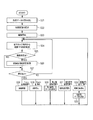
- FIG. 5 is a diagram showing an example of an operation flow of the ultrasonic diagnostic system.
- the cooperative operation of the image management apparatus 4 and the image display apparatus 2 when an operation for storing an ultrasound image is performed in the ultrasound diagnostic apparatus 1 will be mainly described.
- the operation of this ultrasonic diagnostic system is realized by the cooperation of the respective programs of the ultrasonic diagnostic apparatus 1, the image display apparatus 2, and the image management apparatus 4, for example.
- a detailed operation flow of the ultrasonic diagnostic apparatus 1 will be described later with reference to FIGS.
- Detailed operation flows of the image display device 2 and the image management device 4 will be described later with reference to FIGS. 10 and 11, respectively.
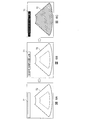
- FIG. 6 is a diagram showing an example of a diagnostic screen displayed on the ultrasonic diagnostic apparatus 1.
- 6A shows an initial screen of a diagnostic screen
- FIG. 6B shows a diagnostic screen when object information is set
- FIG. 6C shows a diagnostic screen when an ultrasound image is captured.
- the diagnostic screens shown in FIGS. 6A to 6C are generated by the image processing unit 13 of the ultrasonic diagnostic apparatus 1 and are sequentially updated according to the control of the control unit 11.
- the diagnostic screen is generated based on, for example, ultrasonic image data and an image format.
- T1 in FIGS. 6A to 6C is a subject display area into which subject identification information is input, and for example, the patient ID and name of the subject are displayed.
- T2 is an ultrasonic image display area in which an ultrasonic image of the examination target region of the subject is input, and for example, a color Doppler image is displayed.
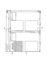
- FIG. 7 is a diagram illustrating an example of a browsing screen displayed on the image display device 2.
- the browsing screen (see FIG. 7) displayed by the image display device 2 has, for example, a plurality of ultrasonic image display areas T3 to T6.
- the image display device 2 sequentially displays the ultrasonic images in the ultrasonic image display areas T3, T4, T5, and T6 every time the ultrasonic image data is received.
- imaging is started by the imaging unit 12 (step S1).
- the imaging state by the imaging unit 12 is continuously performed.
- the ultrasound probe of the imaging unit 12 is pressed against the examination target site of the subject, the captured ultrasound image is input to the region T2 on the diagnostic screen of the ultrasound diagnostic apparatus 1.
- the state is displayed (FIG. 6C).
- the image data on the diagnostic screen on which the ultrasonic image and the subject information are displayed corresponds to “ultrasonic image data” to be stored.
- the control unit 11 first generates, for example, an image ID as identification information for identifying the ultrasound image data to be stored. Then, the ultrasonic diagnostic apparatus 1 transmits the ultrasonic image data with the image ID to the image management apparatus 4 together with the storage instruction signal. Further, the ultrasonic diagnostic apparatus 1 transmits a display instruction signal together with the image ID to the image display apparatus 2 so as to browse and display the image of the ultrasonic image data. Details of the “still image data storage process” performed by the ultrasound diagnostic apparatus 1 will be described later with reference to S30 of FIG. 8 and FIG.
- the image management apparatus 4 In response to receiving the ultrasonic image data and the image ID from the ultrasonic diagnostic apparatus 1, the image management apparatus 4 stores the ultrasonic image data and the image ID in association with each other in the image DB (step S3).
- the image display apparatus 2 In response to receiving the display instruction signal from the ultrasound diagnostic apparatus 1, the image display apparatus 2 sends a request signal for ultrasound image data to the image management apparatus 4 in order to acquire ultrasound image data from the image management apparatus 4. Is transmitted (step S4). At this time, the image display device 2 transmits the image ID attached to the display instruction signal to the image management device 4 together with a request signal for ultrasonic image data.
- the image management device 4 transmits the ultrasonic image data corresponding to the image ID to the image display device 2 (step S5).
- the image display device 2 waits for the transmission of ultrasonic image data from the image management device 4, and displays the image of the ultrasonic image data on the browsing screen in response to receiving the ultrasonic image data (step) S6).
- the image of the ultrasound image data received first on the subject on the browsing screen (see FIG. 7) displayed by the image display device 2 is displayed in the ultrasound image display region T3.
- step S7 still image data saving processing
- the ultrasonic diagnostic apparatus 1 performs the same processing as described above. First, the ultrasound diagnostic apparatus 1 generates an image ID different from the above, and transmits the ultrasound image data with the image ID to the image management apparatus 4 together with a storage instruction signal. Then, the ultrasonic diagnostic apparatus 1 transmits a display instruction signal together with the image ID to the image display apparatus 2.
- the image management device 4 and the image display device 2 perform the processes of steps S8 to S11 in the same manner as steps S3 to S6 in response to the display instruction signal.
- the image display device 2 displays the image of the ultrasonic image data in the ultrasonic image display area T4 of the browsing screen in response to receiving the second ultrasonic image data (step S11).
- an ultrasonic image can be displayed on the image display device 2 without requiring an operation on the image display device 2. For this reason, doctors and the like need to bother searching for corresponding data from the image management device 4 when browsing the ultrasound image on the image display device 2 after imaging the ultrasound image with the ultrasound diagnostic device 1. Disappears.
- FIG. 8 to 9 are diagrams showing an example of a detailed operation flow of the ultrasonic diagnostic apparatus 1.
- FIG. The cooperative operation of the ultrasonic diagnostic apparatus 1 in the ultrasonic diagnostic system described above will be mainly described in step S30.
- control unit 11 When the ultrasonic diagnostic program is executed, the control unit 11 first reads the setting data stored in the storage unit 17 and sets the setting data as a variable in various processes (step S21).
- the setting data includes, for example, address data of the image display device 2 to be linked, the image management device 4, device setting data, display setting data, subject setting data, and the like.
- the address data of the image display device 2 and the image management device 4 to be linked is set as an IP address, for example.
- the control unit 11 transmits a display instruction signal and a storage instruction signal to the image display device 2 and the image management device 4.
- the apparatus setting data is data for setting an imaging condition or the like when the imaging unit 12 images the examination target region of the subject.
- the display setting data is setting data indicating the contents of the subject information displayed on the diagnosis screen shown in FIG.
- the subject setting data is a variable for setting current subject information, such as a patient ID, and is set every time subject information is acquired from the electronic medical record terminal 3.
- setting data such as address data, device setting data, and display setting data of the electronic chart terminal 3 to be linked is input by a doctor or the like on a setting screen (not shown) displayed in step S21, for example. Can be changed.
- control unit 11 After reading the setting data, the control unit 11 causes the image processing unit 13 to generate the initial screen shown in FIG. 6A and display it on the display unit 14 (step S22).
- control part 11 makes the imaging part 12 start imaging, and makes the image process part 13 start the production
- the ultrasound diagnostic apparatus 1 continuously performs imaging by the imaging unit 12 when the power is turned on. Then, when the ultrasound probe of the imaging unit 12 is pressed against the examination target site of the subject, the captured ultrasound image is input to the region T2 on the diagnostic screen of the ultrasound diagnostic apparatus 1. The state is displayed (FIG. 6C).
- the control unit 11 transmits a signal requesting subject information including identification information (patient ID) of the subject to the electronic medical record terminal 3, and sets the currently set subject information from the electronic medical record terminal 3.
- Obtain step S24.
- the subject information is not set, but when the subject information is input to the electronic medical record terminal 3, the subject information is renewed by the ultrasonic diagnostic apparatus 1. It is set automatically without input.
- the control unit 11 periodically acquires subject information from the electronic medical record terminal 3 by polling. Thereby, in the ultrasonic diagnostic apparatus 1 according to the present embodiment, the subject information set in the electronic medical record terminal 3 is sequentially reflected as the subject information.
- the control unit 11 determines whether or not the subject (patient ID) acquired from the electronic medical record terminal 3 has been changed from the currently set subject (patient ID) (step S25).
- the control unit 11 changes the subject information to change the subject to be examined. Is performed (step S26).
- the process of step S27 is performed. However, in the case of a new patient, the patient ID is not registered, and the examination is performed in an unset state.
- control unit 11 changes the currently set subject information (patient ID, etc.) to the acquired subject information (patient ID, etc.). Then, the control unit 11 causes the image processing unit 13 to update the diagnostic screen so that the subject information after the change is displayed on the diagnostic screen (FIG. 6B).
- the control unit 11 determines whether there is an operation on the operation input unit 16 (step S27).
- the control unit 11 is one of the operation buttons provided as the operation input unit 16 for performing an imaging stop operation, an imaging restart operation, a still image saving operation, a moving image saving start operation, a moving image saving end operation, and the like. It is determined whether it has been pressed.
- any one of the operation buttons is pressed, for example, it is stored in a register as an identifiable operation signal, and is input to the control unit 11 via the register.
- step S27: NO when there is no operation to the operation input unit 16 (step S27: NO), the control unit 11 returns to step S24 again and continues the same processing as described above.
- step S27: YES when there is an operation on the operation input unit 16 (step S27: YES), the control unit 11 branches a condition based on the operation signal, and performs an imaging stop operation, an imaging restart operation, a still image saving operation, and a moving image saving. Processing corresponding to each of the start operation and the moving image storage end operation is executed (steps S28 to S33). And the control part 11 returns to step S24 again after performing a corresponding process, and continues the process similar to the above.
- steps S28 to S33 processing corresponding to each of the imaging stop operation, the imaging restart operation, the still image saving operation, the moving image saving start operation, and the moving image saving end operation when the operation input unit 16 is operated will be described (steps S28 to S33). ).
- control unit 11 restarts the operations of the imaging unit 12 and the image processing unit 13 that have been brought into the freeze state by the freeze operation (step S28).
- the control unit 11 causes the imaging unit 12 and the image processing unit 13 to stop operating (step S29).
- the last generated ultrasonic image data is held in the frame buffer of the image processing unit 13, and the display unit 14 stops updating the image while the ultrasonic image data is input.
- the display unit 14 displays a still image of the ultrasound image data generated last by the image processing unit 13.
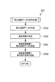
- control unit 11 executes a still image data saving process (step S30).
- FIG. 9 shows details of the still image data storage process.
- the control unit 11 first outputs a storage instruction signal to the image processing unit 13 to generate ultrasonic image data for one frame as a storage target (step S30a).
- the image processing unit 13 generates ultrasonic image data to be saved by encoding the image data of one frame when the still image saving operation is pressed into the JPEG format, and stores it in the storage unit 17.
- the control unit 11 generates a different image ID for each ultrasonic image data to be stored, for example, as information that makes the ultrasonic image data identifiable (step S30b). Subsequently, the control unit 11 attaches an image ID to the generated ultrasonic image data of the still image, and transmits it to the image management apparatus 4 together with a storage instruction signal (step S30c). At this time, if a patient ID is set, the control unit 11 attaches the ultrasound image data to the image management apparatus 4 and transmits the image data to the current patient ID and image ID. And stored in the image DB of the image management apparatus 4.
- control unit 11 transmits a display instruction signal to the image display device 2 together with the image ID (step S30d).
- the storage instruction signal is transmitted from the ultrasonic diagnostic apparatus 1 to the image management apparatus 4 and the display instruction signal is transmitted to the image display apparatus 2, and both apparatuses are shown in steps S3 to S6 in FIG. Such processing is executed.
- step S31 the control unit 11 starts recording moving image data (step S31).
- the control unit 11 causes the image processing unit 13 to start generating moving image data as a storage target.
- the image processing unit 13 generates moving image data by, for example, encoding image data of a plurality of continuous frames in the MPEG format, and stores the moving image data in the storage unit 17.
- the control unit 11 stops the recording of the moving image data started by the moving image storage start operation (step S32). Then, the control unit 11 generates an image ID and transmits it to the image management apparatus 4 together with the moving image data stored in the storage unit 17 and the image ID, as in the case of the storage processing of the image data of the still image.
- the moving image data is stored in the image DB of the image management device 4 (step S33).
- control part 11 returns to step S24 again after performing the process corresponding to these operation, and continues the process similar to the above.
- the control unit 11 of the ultrasonic diagnostic apparatus 1 repeats the above processing and executes the examination of the subject.
- FIG. 10 is a flowchart showing an example of the operation of the image display device 2.
- the operation of the image display device 2 is the operation of the control unit 21 and is realized, for example, when the CPU executes an image browsing program.
- the control unit 21 first performs initial setting and generates the ultrasonic image browsing screen shown in FIG. 7 (step S41). In this initial setting, the IP address of the ultrasound diagnostic apparatus 1 to be linked and the IP address of the image management apparatus 4 are set.
- the image display device 2 waits to receive a display instruction signal from the ultrasound diagnostic device 1 (step S42: NO).
- a display instruction signal is received from the ultrasonic diagnostic apparatus 1
- the display instruction signal is stored in a register included in the image display apparatus 2 and identified by the control unit 21.
- the image display apparatus 2 when the display instruction signal is received from the ultrasound diagnostic apparatus 1 (step S42: YES), the image display apparatus 2 includes the identification information (here, the image ID) attached to the display instruction signal.
- An image data request signal is transmitted to the image management device 4 (step S43).
- the image display apparatus 2 displays the image of the said ultrasonic image data on an ultrasonic image browsing screen, when corresponding ultrasonic image data is received from the image management apparatus 4 (step S44). After displaying the image of the ultrasonic image data on the ultrasonic image browsing screen, the image display device 2 returns to step S42 again and waits to receive a display instruction signal from the ultrasonic diagnostic device 1.
- the image display device 2 preferably receives subject information from the ultrasonic diagnostic device 1 and the electronic medical record terminal 3. For example, when receiving a display instruction signal from the ultrasound diagnostic apparatus 1, the image display apparatus 2 receives subject information (for example, patient ID) together with the image ID. By doing so, the image display device 2 initializes the ultrasound image browsing screen every time the subject is changed without requiring an operation by a doctor or the like, and displays the ultrasound image of the subject before the change. Can be hidden.
- subject information for example, patient ID
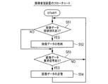
- FIG. 11 is a flowchart showing an example of the operation of the image management apparatus 4.
- the operation of the image management apparatus 4 is an operation of a control unit (not shown) included in the image management apparatus 4, and is realized by, for example, the CPU executing an image management program.
- the image management apparatus 4 determines whether an ultrasonic image data storage instruction signal has been received from the ultrasonic diagnostic apparatus 1 (step S51).
- the storage instruction signal is received (step S51: YES)
- the received ultrasonic image data is stored in the image DB in association with the image ID attached to the storage instruction signal (step S52).
- the storage instruction signal is stored in a register included in the image management apparatus 4 and is identified by the control unit of the image management apparatus 4.
- step S51 when the storage instruction signal is not received from the ultrasound diagnostic apparatus 1 (step S51: NO), the image management apparatus 4 determines whether the image data request signal is received from the image display apparatus 2 (step S53). .
- step S53: YES When the image data request signal is received (step S53: YES), the ultrasonic image data of the corresponding image ID is transmitted to the image display device 2 (step S54).
- step S53: NO when the image data request signal is not received (step S53: NO), the image management apparatus 4 returns to step S51 and continues the monitoring process again.
- an ultrasonic image can be displayed on the image display device 2 without requiring an operation on the image display device 2.
- the ultrasonic diagnostic apparatus 1 adds identification information such as an image ID to the ultrasonic image data and stores it in the image management apparatus 4, and instructs the image display apparatus 2 to display the identification information together with the identification information.
- the ultrasonic diagnostic apparatus 1 is the main component, and both apparatuses can be automatically controlled. For this reason, doctors and the like need to bother searching for corresponding data from the image management device 4 when browsing the ultrasound image on the image display device 2 after imaging the ultrasound image with the ultrasound diagnostic device 1. Disappears.
- the ultrasonic diagnostic apparatus 1 generates information for identifying an ultrasonic image such as an image ID and operates the image management apparatus 4 and the image display apparatus 2. Therefore, even for a new patient who does not have a patient ID or the like, the image management apparatus 4 can store ultrasonic image data in an identifiable manner, and the image display apparatus 2 can acquire the ultrasonic image data. Therefore, doctors create a new medical record if they are new patients, and store them in association with existing medical records if they are new patients. No need to run. By doing so, a doctor or the like can use the ultrasonic diagnostic apparatus 1 with a sense of using a stethoscope without burden.
- the ultrasonic diagnostic apparatus 1 transmits an ultrasonic image display instruction signal to the image display apparatus 2 every time a still image storage operation (storage instruction signal) is performed.
- the ultrasonic diagnostic apparatus 1 may be configured to set conditions for transmitting the display instruction signal.
- FIG. 12 is a diagram illustrating an example of an operation flow of the ultrasonic diagnostic system according to the present modification.
- the ultrasonic diagnostic apparatus 1 transmits a storage instruction signal to the image management apparatus 4, but transmits a display instruction signal to the image display apparatus 2. It is a mode that does not transmit.
- the operations of the other steps S1a to S7a, S8a to S9a are the same as the operations of steps S1 to S7 in FIG. 5, and the description thereof is omitted here.
- the ultrasound diagnostic apparatus 1 sets, as setting data, a condition setting for determining whether or not to transmit a display instruction signal, and a setting for defining timing for transmitting the display instruction signal Data on The control unit 11 of the ultrasonic diagnostic apparatus 1 determines the output mode of the display instruction signal based on the setting data.
- the ultrasound diagnostic apparatus 1 determines whether to transmit a display instruction signal based on the setting data, and does not transmit a display instruction signal when the number of still image storage operations is equal to or greater than a predetermined number. In the case of an operation for saving moving image data, a display instruction signal is not transmitted.
- the control unit 11 of the ultrasound diagnostic apparatus 1 stores the number of still image saving operations for the ultrasound image related to the same subject in the storage unit 17 and increments the number of times each time the still image saving operation is performed. It may be configured to do.
- the ultrasound image browsing screen of the image display device 2 can display only one ultrasound image
- the ultrasound image displayed on the ultrasound image viewing screen is saved each time the ultrasound image is saved. It is possible to prevent frequent replacement.
- a doctor or the like can perform a medical examination by looking at the first acquired ultrasonic image.
- the ultrasound diagnostic apparatus 1 can determine the timing for transmitting the display instruction signal based on the image type of the image data to be stored. For example, when displaying moving image data or the like on the image display apparatus 2, the ultrasound diagnostic apparatus 1 changes the timing of outputting the display instruction signal from the timing of transmitting the storage instruction signal to the image management apparatus 4 for a certain time. Can be set to delay.
- the ultrasound diagnostic apparatus 1 changes the timing of outputting the display instruction signal from the timing of transmitting the storage instruction signal to the image management apparatus 4 for a certain time. Can be set to delay.
- the ultrasonic diagnostic apparatus 1 transmits a storage instruction signal to the image management device 4. There is a risk of having a certain time to complete.
- the image ID is shown as an example of “identification information” attached to the ultrasound image data by the ultrasound diagnostic apparatus 1.
- the image ID is not necessarily an image ID as long as the information can identify the ultrasound image data. There is no need, and a diagnosis ID indicating the order of the diagnosis may be used.
- the image management apparatus 4 and the image display apparatus 2 use the diagnosis ID and the ultrasonic diagnosis apparatus 1.
- a plurality of ultrasonic image data may be identified based on the reception time of the instruction signal.
- the timing at which the “save instruction signal” is generated the timing at which a doctor or the like performs an operation to save a still image of an ultrasound image is shown.
- the aspect can be variously modified as long as it is an operation or the like for storing the sonic image data in the image management apparatus 4. For example, if a scan start operation is required, a storage instruction signal may be generated at regular intervals when the scan start operation is performed. Further, when displaying the ultrasonic image data of the moving image on the image display device 2, the timing at which the moving image storage end operation is performed may be used.
- the image display apparatus 2 and the electronic medical record terminal 3 were shown as an example of a structure as an example of a structure of an ultrasonic diagnosing system, the image display apparatus 2 and the electronic medical record terminal 3 were shown. May be configured as a single unit. In other words, an image display device 2 having a function program for the electronic medical record terminal 3 may be used.
- An ultrasonic diagnostic apparatus 1 configured to be communicable with an image display apparatus 2 that displays an ultrasonic image obtained by imaging an examination target region of a subject and an image management apparatus 4 that manages image data of the ultrasonic image.
- the image data of the ultrasonic image is transmitted together with the identification information to the image management apparatus 4 in response to an input unit 16 that receives an operation input from the operator and a storage instruction signal generated based on the operation input.
- the image data is stored in association with the identification information, and a display instruction signal for displaying the image data of the ultrasonic image is transmitted to the image display device 2 together with the identification information.
- a control unit 11 that acquires image data of the ultrasonic image from the image management device 4 is disclosed.
- the identification information may be generated by the control unit 11.
- control unit 11 does not transmit the display instruction signal to the image display device 2 when the number of instructions of the storage instruction signal related to the same subject is a predetermined number or more. May be.
- control unit 11 may determine the timing for transmitting the display instruction signal based on the image type of the image data.
- the storage instruction signal may be generated in response to an input of an operation for storing the still image of the ultrasonic image.
- the image display apparatus 2 that displays an ultrasonic image obtained by imaging the examination target region of the subject, and the ultrasonic diagnostic apparatus 1 that can communicate with the image management apparatus 4 that manages image data of the ultrasonic image are executed.
- An ultrasound diagnostic program for receiving an operation input from an operator and a storage instruction signal generated on the basis of the operation input, the image management apparatus 4 is provided with an image of the ultrasound image. Display instruction signal for transmitting data together with identification information, storing the image data in association with the identification information, and causing the image display device 2 to display the image data of the ultrasonic image together with the identification information
- An ultrasonic diagnostic program is disclosed that includes processing for transmitting image data of the ultrasonic image from the image management apparatus 4.
- the present disclosure can be suitably used as a medical diagnostic apparatus of a medical diagnostic system.
Landscapes
- Health & Medical Sciences (AREA)
- Engineering & Computer Science (AREA)
- Life Sciences & Earth Sciences (AREA)
- General Health & Medical Sciences (AREA)
- Medical Informatics (AREA)
- Public Health (AREA)
- Biomedical Technology (AREA)
- Nuclear Medicine, Radiotherapy & Molecular Imaging (AREA)
- Radiology & Medical Imaging (AREA)
- Physics & Mathematics (AREA)
- Molecular Biology (AREA)
- Veterinary Medicine (AREA)
- Biophysics (AREA)
- Pathology (AREA)
- Animal Behavior & Ethology (AREA)
- Heart & Thoracic Surgery (AREA)
- Surgery (AREA)
- Epidemiology (AREA)
- Primary Health Care (AREA)
- Computer Networks & Wireless Communication (AREA)
- Business, Economics & Management (AREA)
- General Business, Economics & Management (AREA)
- Ultra Sonic Daignosis Equipment (AREA)
Abstract
被検体の検査対象部位を撮像した医用画像を表示する画像表示装置(2)、及び当該医用画像の画像データを管理する画像管理装置(4)と通信可能に構成された医用診断装置(1)であって、操作者の操作入力を受け付ける入力部(16)と、前記操作入力に基づいて生成される保存指示信号に応じて、前記画像管理装置(4)に対して、前記医用画像の画像データを識別情報とともに送信して当該画像データを当該識別情報と関連付けて格納させ、且つ、前記画像表示装置(2)に対して、前記識別情報とともに、前記医用画像の画像データを表示させるための表示指示信号を送信して、前記医用画像の画像データを前記画像管理装置(4)から取得させる制御部(11)と、を備える。
Description
本発明は、医用診断装置、及び医用診断プログラムに関する。
超音波診断装置、X線診断装置、MRI(Magnetic Resonance Imaging)装置等のモダリティで撮像された超音波画像を、患者情報と対応付けて医用画像管理装置(PACSサーバ)に保存・管理するとともに、画像表示用の端末装置(PACSクライアント)のビューア画面に当該超音波画像を表示して、医師等による読影診断に供する医用画像管理システム(PACS:Picture Archiving and Communication System)が知られている。
モダリティにより診断対象の患者の撮像が行われた場合、医師等は、当然、画像表示用の端末装置のビューア画面でその超音波画像を参照しながら診断を行う。しかしながら、かかる医用画像管理システムにおいては、モダリティで撮像された超音波画像は、医用画像管理装置に取り込まれて保存・管理される。そのため、当該超音波画像を参照する際には、医師等は、医用画像管理装置から対象となる超音波画像を検索して読み出す操作が必要となり、医師等の操作負担が大きかった。
このような背景から、例えば、特許文献1には、画像表示用の端末装置のプログラムと、モダリティのプログラムとを連携させ、画像表示用の端末装置に設けられた画像取り込みボタンが押下されると、モダリティから超音波画像データを取り込んで、ビューア画面に表示することが記載されている。
ところで、従来のシステム(特許文献1)においては、画像表示用の端末装置(以下、「画像表示装置」と言う)の側に医師や技師等の操作者(以下、「医師等」と言う)が座った状態で、当該画像表示装置のビューア画面上で操作して、モダリティに撮像指示及び当該超音波画像データの取り込み指示を行うことを想定したものとなっている。
しかしながら、超音波診断装置に関して言えば、実際の医療現場においては、例えば、診察室で医師等による問診が行われた後、その場で、医師等による撮像を行う用に供されたりする。そのため、医師等は、超音波診断装置の側にいる状態で、当該超音波診断装置の超音波探触子を、患者の検査対象部位に押し当てながら、当該超音波診断装置の操作を行ったりする。言い換えると、超音波診断装置においては、画像表示装置の側に医師等が座った状態では、却って超音波診断装置の操作性を悪化させるおそれもある。尚、図13は、上記した超音波診断システムの一例を示す図である。図13中において、1は超音波診断装置、2は画像表示装置、5は電子カルテ管理装置、P1は医師等、P2は患者を表す。
加えて、従来のシステム(特許文献1)においては、画像表示装置のプログラムと、モダリティのプログラムとを連携させる際に、患者ID等の被検体情報による紐付け設定が必要となる。そのため、再来患者の場合には、電子カルテ等の被検体情報を用い、新規患者の場合には、新たな被検体情報の設定を行うという作業が必要となる。その結果、医師等が、超音波診断装置を頻繁に使用する際には、大きな負担になっていた。
そこで、本発明は、画像表示装置において医用画像を閲覧する際に、医師等による操作負担を軽減することを可能とする医用診断装置、及び医用診断プログラムを提供することを目的とする。
前述した課題を解決する主たる本発明は、被検体の検査対象部位を撮像した医用画像を表示する画像表示装置、及び当該医用画像の画像データを管理する画像管理装置と通信可能に構成された医用診断装置であって、操作者の操作入力を受け付ける入力部と、前記操作入力に基づいて生成される保存指示信号に応じて、前記画像管理装置に対して、前記医用画像の画像データを識別情報とともに送信して当該画像データを当該識別情報と関連付けて格納させ、且つ、前記画像表示装置に対して、前記識別情報とともに、前記医用画像の画像データを表示させるための表示指示信号を送信して、前記医用画像の画像データを前記画像管理装置から取得させる制御部と、を備えることを特徴とする医用診断装置である。
又、被検体の検査対象部位を撮像した医用画像を表示する画像表示装置、及び当該医用画像の画像データを管理する画像管理装置と通信可能に構成された医用診断装置に実行させる医用診断プログラムであって、操作者の操作入力を受け付ける処理と、前記操作入力に基づいて生成される保存指示信号に応じて、前記画像管理装置に対して、前記医用画像の画像データを識別情報とともに送信して当該画像データを当該識別情報と関連付けて格納させ、且つ、前記画像表示装置に対して、前記識別情報とともに、前記医用画像の画像データを表示させるための表示指示信号を送信して、前記医用画像の画像データを前記画像管理装置から取得させる処理と、を備えることを特徴とする医用診断プログラムである。
本発明に係る医用診断装置によれば、画像表示装置において超音波画像を閲覧する際に、医師等による操作負担を軽減することができる。
以下、図1~図4を参照して、本実施形態に係る超音波診断システムの構成の一例について説明する。
図1は、超音波診断システムの全体構成の一例を示す図である。図2は、超音波診断装置の機能ブロックの一例を示す図である。図3は、超音波診断装置の外観を示す図である。図4は、画像表示装置の機能ブロックの一例を示す図である。
本実施形態に係る超音波診断システムは、例えば、超音波診断装置1、画像表示装置2、電子カルテ端末3、画像管理装置4、電子カルテ管理装置5、通信回線6を含んで構成される(図1を参照)。
ここでは、超音波診断システムが、病院に用いられる態様を説明する。超音波診断装置1、画像表示装置2及び電子カルテ端末3は、病院の診察室に設置され、画像管理装置4及び電子カルテ管理装置5は、サーバ室に設置されている。そして、これらの装置は、通信回線6を介して、通信接続されている。尚、通信回線6は、例えば、病院内に設置されたLAN(Local Area Network)回線であって、これらの装置は、DICOM(Digital Imaging and Communication in Medicine)規格に従ってデータ通信するものとする。
まず、病院において、患者を診察する際の一連の流れについて説明する。
病院には、レセプト端末(図示せず)が設けられており、患者が来院した場合、レセプト端末が電子カルテ管理装置5から当該患者の電子カルテを受信する。そして、窓口担当者が、レセプト端末の表示画面にて電子カルテの内容を確認して、レセプト端末から電子カルテ端末3へ電子カルテを送信する。
診察室内には、超音波診断装置1、画像表示装置2、電子カルテ端末3が設置されており、医師が、当該超音波診断装置1、画像表示装置2、電子カルテ端末3を用いて診察を行う。電子カルテ端末3には、レセプト端末から電子カルテを受信した順序で、複数の診察対象の患者の電子カルテが記憶される。これにより、患者は診察待ちの状態となり、電子カルテ端末3は、医師により診察対象の患者の更新操作が行われると、表示画面に次の診察対象患者の電子カルテの内容を表示する。
医師は、当該診察対象の患者の診察を行い、診察内容を電子カルテ端末3に入力する。この際、医師は、必要に応じて超音波診断装置1を用いて、患者の検査を行う。超音波診断装置1は、検査を行った結果、取得した超音波画像を含む画像データを画像管理装置4に保存する。画像管理装置4に保存された画像データは、画像表示装置2によって読み出され、当該画像表示装置2の表示画面にその超音波画像が表示される。医師は、当該画像表示装置2の表示画面に表示された医用画像を使用して患者に説明を行うとともに、所見を電子カルテ端末3に入力する。診察が終了して、医師により電子カルテ端末3に診察終了指示が入力されると、電子カルテ端末3は、レセプト端末に電子カルテを送信する。そして、医師は、診察対象の患者の更新操作を行い、次の患者の診察を行う。
超音波診断装置1は、被検体の生体内部組織の状態を超音波画像にして表示出力する装置である(図2、図3を参照)。尚、以下では、超音波診断装置1で検査する対象の患者のことを「被検体」と称し、当該被検体に関するデータを「被検体情報」とも称する。
ここでは、超音波診断装置1は、例えば、超音波画像としてカラードプラ画像を生成するものとする。カラードプラ画像は、生体内の断層像をグレースケールで表現したBモード画像(Brightness mode Imaging)に重ねて、血流や心筋壁等の体組織の動きを色で表現したカラー画像(Color Flow Imaging)を表示することで生成される。
超音波診断装置1は、制御部11、撮像部12、画像処理部13、表示部14、通信部15、操作入力部16、記憶部17を含んで構成される(図2を参照)。
制御部11は、超音波診断装置1の各部の動作を統括制御する。制御部11は、例えば、CPUがプログラムを実行することによって、実現される。
撮像部12は、被検体の検査対象部位を撮像して、超音波画像を生成するためのフレーム単位となる二次元データを生成する。
撮像部12は、複数の振動子によって構成される超音波探触子を備え、当該超音波探触子を被検体の腹部等に押し当てた状態で、被検体内に対して超音波ビームを送信する。そして、当該超音波探触子は、この被検体内で反射した超音波エコーを受信し、受信信号を生成する。撮像部12は、Bモード画像を生成する際には、当該超音波エコーによって生成された受信信号の信号強度の時間的変化をラインメモリに蓄積する。そして、撮像部12は、超音波探触子の複数の振動子を走査(スキャン)して、超音波ビームを送受信させる方向を切り替え、各走査位置での当該受信信号をラインメモリに順次蓄積させることでフレーム単位となる二次元データを生成する。Bモード画像は、当該二次元データに係る受信信号の信号強度を輝度値に変換することによって生成される。又、撮像部12は、カラー画像を生成する際には、連続して送信したパルス状の超音波ビームの、同じ深さ位置からの超音波エコーを検出する。そして、撮像部12は、当該連続する超音波エコーの位相差に基づいて、当該深さ位置に存在する血流の速度、パワー、分散を算出して血流信号を生成する。撮像部12は、Bモード画像と同様に、超音波探触子を走査(スキャン)して、超音波ビームを送受信させる方向を切り替えることで、各走査位置での血流信号をラインメモリに順次蓄積し、フレーム単位となる二次元データを生成する。カラー画像は、当該二次元データに係る血流信号の速度、パワー、分散をRGB値に変換することによって生成される。
画像処理部13は、撮像部12からフレーム単位となる二次元データを取得して、超音波画像を生成する。具体的には、画像処理部13は、上記したとおり、受信信号の信号強度に係る二次元データからBモード画像を生成し、血流信号の速度、パワー、分散に係る二次元データからカラー画像を生成する。そして、画像処理部13は、Bモード画像上に動きのあるカラー画像を重畳することによって、カラードプラ画像を生成する。
画像処理部13は、このようにして生成した超音波画像に、被検体の識別情報を示す画像を付した画像データ(以下、「超音波画像データ」とも言う)を生成して表示部14に表示させる(図6を参照して後述する)。画像処理部13は、上記した画像を生成するためのバッファメモリ、生成した画像の画像データを保持可能な大容量メモリーを備えている。そして、画像処理部13は、制御部11からの保存指示に応じて、当該画像データをエンコードして記憶部17に送出して、静止画像データ又は動画画像データとして記憶させる。尚、画像処理部13は、超音波画像に対して、座標変換処理を施したり、データ補間処理を施したりして、表示部14に表示可能な画像データに変換して出力する。
表示部14は、LCDやCRTディスプレイ等の表示装置である。表示部14は、画像処理部13によって生成された超音波画像の画像データに基づいて、超音波画像を表示画面上に表示する。
通信部15は、通信回線6を介して電子カルテ端末3、画像管理装置4、電子カルテ管理装置5等の外部機器とデータの送受信を行うための通信インタフェイスであり、例えば、LANアダプターによって構成される。
操作入力部16(入力部)は、例えば、タッチパネルや操作ボタンであり、医師等の入力操作を受け付ける。医師等によって操作入力部16に入力されたデータは、操作信号として制御部11に出力される。本実施形態に係る超音波診断装置1は、操作入力部16として、撮像停止操作、撮像再開操作、静止画保存操作、動画保存開始操作、動画保存終了操作等を行うための操作ボタンを備えている。
記憶部17は、例えば、ROM、RAM、HDD等を含んで構成され、システムプログラム、当該システムプログラム上で実行可能な超音波診断プログラム等の各種処理プログラムや、各種データ、及び演算処理において一時的に記憶するためのワークエリアを有する。
又、記憶部17は、上記のようにして生成された超音波画像を含む画像データを保存する。記憶部17は、例えば、画像データとして、1フレーム分の静止画の画像データである静止画像データと、数フレーム分の静止画像データを動画表示可能に生成された動画データとを保存することができる。尚、記憶部17に格納された超音波画像の画像データは、その後、画像管理装置4に送信され、当該画像管理装置4において管理される。
画像表示装置2は、超音波診断装置1で撮像された超音波画像を閲覧するためのするための情報処理装置である。画像表示装置2は、画像管理装置4から超音波画像の画像データを取得して、当該画像を表示する。
画像表示装置2は、例えば、制御部21、記憶部22、通信部23、入力部24、表示部25を含んで構成されるコンピュータである(図4を参照)。
制御部21は、画像表示装置2の各部を統括制御するもので、CPU(Central Processing Unit)がコンピュータプログラムを実行することで実現される。
記憶部22は、RAM、ROM、HDD等を含んで構成され、システムプログラム、当該システムプログラム上で実行可能な画像閲覧プログラム、アプリケーションに用いられる画像フォーマットデータ等を記憶する。
通信部23は、通信回線6を介して超音波診断装置1、画像管理装置4等の外部機器とデータの送受信を行うための通信インタフェイスであり、例えば、LANアダプターによって構成される。
入力部24は、医師等が画像表示装置2に対して操作入力を行うためのユーザインタフェイスであり、例えば、キーボードによって構成される。
表示部25は、超音波画像を表示するもので、例えば、液晶ディスプレイによって構成される。
電子カルテ端末3は、被検体に関する情報を電子カルテとして表示し、医師等が診察結果を入力したりするための情報処理装置である。電子カルテ端末3は、画像表示装置2と同様に、コンピュータであり、ここでの詳細な説明は省略する。
画像管理装置4は、例えば、超音波画像データを保存及び管理するサーバ装置である。画像管理装置4は、画像表示装置2と同様に、コンピュータであり、ここでの詳細な説明は省略する。
画像管理装置4は、画像DB(Data Base)を備えており、超音波画像データに、例えば、患者ID、画像ID、検査情報等の画像に関する情報等を付帯させて、これらの情報を記憶する。尚、検査情報には、検査日、当該画像ファイルの保存時刻、表示深度の他、検査を識別する検査ID、検査名、受付番号、検査目的、検査内容等の検査に関する情報が含まれる。
電子カルテ管理装置5は、電子カルテを保存及び管理するサーバ装置である。電子カルテ管理装置5は、画像表示装置2と同様に、コンピュータであり、ここでの詳細な説明は省略する。
電子カルテ管理装置5は、電子カルテDB(Data Base)を備えており、当該電子カルテDBに患者毎の電子カルテを保存する。電子カルテには、例えば、患者名、患者ID、性別、生年月日、住所、職業、診察結果等の患者に関する情報が含まれている。尚、電子カルテのデータ内容の一部又は全部が、被検体情報として、電子カルテ端末3や超音波診断装置1にて表示される。
(超音波診断システムの動作)
次に、図5~図7を参照して、本実施形態に係る超音波診断システムの動作フローの概略について説明する。
次に、図5~図7を参照して、本実施形態に係る超音波診断システムの動作フローの概略について説明する。
図5は、超音波診断システムの動作フローの一例を示す図である。ここでは、主に、超音波診断装置1において超音波画像を保存するための操作がなされた場合の、画像管理装置4と画像表示装置2の連携動作について説明する。尚、この超音波診断システムの動作は、例えば、超音波診断装置1、画像表示装置2、画像管理装置4ぞれぞれのプログラムが協働することによって実現される。超音波診断装置1の詳細な動作フローについては、図8~図9を参照して後述する。又、画像表示装置2、画像管理装置4の詳細な動作フローについては、それぞれ図10、図11を参照して後述する。
図6は、超音波診断装置1に表示される診断画面の一例を示す図である。尚、図6Aは診断画面の初期画面、図6Bは被検体情報が設定されたときの診断画面、図6Cは超音波画像が撮像されたときの診断画面を示している。図6A~図6Cに示す診断画面は、超音波診断装置1の画像処理部13によって生成され、制御部11の制御に応じて順次更新される。診断画面は、例えば、超音波画像データと画像フォーマットに基づいて生成される。
ここで、図6A~図6CのT1は、被検体の識別情報が入力される被検体表示領域であり、例えば、被検体の患者IDや名前が表示される。T2は、被検体の検査対象部位の超音波画像が入力される超音波画像表示領域であり、例えば、カラードプラ画像が表示される。
図7は、画像表示装置2に表示される閲覧画面の一例を示す図である。尚、画像表示装置2が表示する閲覧画面(図7を参照)は、例えば、複数の超音波画像表示領域T3~T6を有する。そして、画像表示装置2は、超音波画像データを受信する毎に、順に、超音波画像表示領域T3、T4、T5、T6に超音波画像を表示する。
まず、超音波診断装置1において、電源が投入され、超音波診断プログラムが開始されると、撮像部12によって撮像が開始される(ステップS1)。本実施形態に係る超音波診断装置1は、電源が投入されると、当該撮像部12による撮像状態が継続して行われることになる。そして、撮像部12の超音波探触子が、被検体の検査対象部位に押し当てられた場合、超音波診断装置1の診断画面には、撮像された超音波画像が領域T2に入力された状態で表示される(図6C)。尚、この超音波画像と被検体情報とが表示された診断画面の画像データが、保存対象となる「超音波画像データ」に相当する。
そして、ここでは、超音波診断装置1において、医師等によって静止画保存操作がなされると、静止画像データの保存処理が行われる(ステップS2)。この際、制御部11は、まず、保存対象の超音波画像データを識別させる識別情報として、例えば、画像IDを生成する。そして、超音波診断装置1は、画像管理装置4に対して、当該画像IDが付された超音波画像データを格納指示信号とともに送信する。更に、超音波診断装置1は、当該超音波画像データの画像を閲覧表示させるべく、画像表示装置2に対して表示指示信号を当該画像IDとともに送信する。尚、超音波診断装置1が行う「静止画像データの保存処理」の詳細については、図8のS30、図9を参照して後述する。
画像管理装置4は、超音波診断装置1から超音波画像データと画像IDを受信するに応じて、当該超音波画像データと画像IDを関連付けた状態で画像DBに格納する(ステップS3)。
画像表示装置2は、超音波診断装置1から表示指示信号を受信するに応じて、超音波画像データを画像管理装置4から取得するべく、画像管理装置4に対して超音波画像データの要求信号を送信する(ステップS4)。このとき、画像表示装置2は、表示指示信号に付された画像IDを超音波画像データの要求信号とともに、画像管理装置4に対して送信する。
画像管理装置4は、画像表示装置2から超音波画像データの要求信号を受信するに応じて、画像IDに対応する超音波画像データを画像表示装置2に対して送信する(ステップS5)。
画像表示装置2は、画像管理装置4から超音波画像データが送信されることを待ち受け、当該超音波画像データを受信するに応じて、閲覧画面に当該超音波画像データの画像を表示する(ステップS6)。尚、ここでは、画像表示装置2が表示する閲覧画面(図7を参照)の、当該被検体に関して一番最初に受信した超音波画像データの画像を超音波画像表示領域T3に表示させる。
その後、超音波診断装置1において、再度、医師等によって静止画保存操作がなされると、静止画像データの保存処理が行われる(ステップS7)。
この場合も、超音波診断装置1は、上記と同様の処理を行う。超音波診断装置1は、まず、上記とは異なる画像IDを生成し、画像管理装置4に対して、当該画像IDが付された超音波画像データを格納指示信号とともに送信する。そして、超音波診断装置1は、画像表示装置2に対して当該画像IDとともに表示指示信号を送信する。
画像管理装置4及び画像表示装置2は、当該表示指示信号に応じて、上記ステップS3~S6と同様に、ステップS8~S11の処理を行う。尚、画像表示装置2は、2枚目の超音波画像データを受信するに応じて、閲覧画面の超音波画像表示領域T4に当該超音波画像データの画像を表示する(ステップS11)。
このように、本実施形態に係る超音波診断システムでは、画像表示装置2での操作を要することなく、超音波画像を当該画像表示装置2に表示させることができる。そのため、医師等は、超音波診断装置1で超音波画像を撮像した後、画像表示装置2で当該超音波画像を閲覧する際、わざわざ画像管理装置4から対応するデータを検索する操作をする必要がなくなる。
次に、本実施形態に係る超音波診断システムの超音波診断装置1、画像表示装置2、画像管理装置4の各装置の動作の詳細について説明する。
(超音波診断装置の動作)
図8~図9は、超音波診断装置1の詳細な動作フローの一例を示す図である。尚、上記した超音波診断システムにおける超音波診断装置1の連携動作は、主にステップS30で説明する。
図8~図9は、超音波診断装置1の詳細な動作フローの一例を示す図である。尚、上記した超音波診断システムにおける超音波診断装置1の連携動作は、主にステップS30で説明する。
図8~図9に示す各ステップは、超音波診断装置1の制御部11が超音波診断プログラムに従って実行するものとする。
超音波診断プログラムを実行した際、制御部11は、まず、記憶部17に格納された設定データの読み出しを行い、各種処理における変数として当該設定データを設定する(ステップS21)。
ここで、設定データには、例えば、連携対象の画像表示装置2、画像管理装置4のアドレスデータ、装置設定データ、表示設定データ、被検体設定データ等が含まれる。連携対象の画像表示装置2、画像管理装置4のアドレスデータは、例えば、IPアドレスとして設定される。制御部11は、かかる画像表示装置2、画像管理装置4に対して、表示指示信号、格納指示信号を送信する。又、装置設定データは、撮像部12で被検体の検査対象部位を撮像する際の撮像条件等を設定するデータである。又、表示設定データは、図6に示した診断画面に表示する被検体情報の内容を示す設定データである。この表示設定データに基づいて、診断画面には、例えば、上記した患者ID、名前に加えて、性別、検査履歴、年齢、検査対象部位等を表示させることができる。被検体設定データは、患者ID等、現在の被検体情報を設定する変数であって、電子カルテ端末3から被検体情報を取得する毎に設定される。尚、連携対象の電子カルテ端末3のアドレスデータ、装置設定データ、表示設定データ等の設定データは、例えば、このステップS21で表示される設定画面(図示せず)において、医師等が入力操作することによって変更することができる。
制御部11は、設定データを読み出した後、画像処理部13に、図6Aに示す初期画面の生成を行わせ、表示部14に表示させる(ステップS22)。
そして、制御部11は、撮像部12に撮像を開始させて、画像処理部13に超音波画像の生成処理を開始させる(ステップS23)。より詳細には、制御部11は、撮像部12に撮像指示信号を出力し、超音波探触子の複数の振動子を走査(スキャン)させて、Bモード画像及びカラー画像に係るフレーム単位となる二次元データの生成を開始させる。そして、制御部11は、画像処理部13に画像生成指示信号を出力し、撮像部12で生成された二次元データに基づいて、超音波画像データの生成を開始させる。又、制御部11は、表示部14に表示指示信号を出力し、画像処理部13で生成された超音波画像データの画像を表示させる。
本実施形態に係る超音波診断装置1は、上記したとおり、電源が投入されると、当該撮像部12によって継続して撮像を行う。そして、撮像部12の超音波探触子が、被検体の検査対象部位に押し当てられた場合、超音波診断装置1の診断画面には、撮像された超音波画像が領域T2に入力された状態で表示される(図6C)。
まず、制御部11は、電子カルテ端末3に対して被検体の識別情報(患者ID)を含む被検体情報を要求する信号を送信し、電子カルテ端末3から現在設定されている被検体情報を取得する(ステップS24)。超音波診断装置1を起動した直後には、被検体情報は未設定状態であるが、電子カルテ端末3に被検体情報が入力されると、当該被検体情報は、超音波診断装置1で改めて入力されることなく自動的に設定される。ここでは、制御部11は、電子カルテ端末3から、ポーリングによって定期的に被検体情報を取得するものとする。これによって、本実施形態に係る超音波診断装置1においては、電子カルテ端末3に設定された被検体情報が、逐次、被検体情報として反映される構成になっている。
続いて、制御部11は、電子カルテ端末3から取得した被検体(患者ID)が、現在設定されている被検体(患者ID)から変更されたかを判定する(ステップS25)。制御部11は、電子カルテ端末3から取得した患者IDが、現在設定されている患者IDと異なる場合(ステップS25:YES)、検査対象たる被検体を変更するべく、被検体情報を変更する処理を行う(ステップS26)。一方、当該取得した患者IDが、現在設定されている患者IDと同じ場合(ステップS25:NO)、ステップS27の処理を行う。但し、新規患者の場合には、患者IDが未登録であり、未設定状態で検査が行われる。
ステップS26の被検体情報変更処理では、制御部11は、現在設定されている被検体情報(患者ID等)を、取得した被検体情報(患者ID等)に変更する。そして、制御部11は、当該変更後の被検体情報が診断画面に表示されるように、画像処理部13に対して、診断画面の更新を行わせる(図6B)。
次のステップとして、制御部11は、操作入力部16への操作があったか判定する(ステップS27)。このステップでは、制御部11は、操作入力部16として設けられた撮像停止操作、撮像再開操作、静止画保存操作、動画保存開始操作、動画保存終了操作等を行うための操作ボタンのいずれかが押下されたかを判定する。尚、いずれかの操作ボタンが押下された場合には、例えば、識別可能な操作信号としてレジスタに格納され、当該レジスタを介して制御部11に入力される。
具体的には、制御部11は、操作入力部16への操作がない場合(ステップS27:NO)、再度、ステップS24に戻って、上記と同様の処理を継続する。一方、制御部11は、操作入力部16への操作があった場合(ステップS27:YES)、操作信号に基づいて条件分岐して、撮像停止操作、撮像再開操作、静止画保存操作、動画保存開始操作、動画保存終了操作それぞれに対応する処理を実行する(ステップS28~S33)。そして、制御部11は、対応する処理を実行した後、再度、ステップS24に戻って、上記と同様の処理を継続する。
ここで、操作入力部16への操作がなされた場合の撮像停止操作、撮像再開操作、静止画保存操作、動画保存開始操作、動画保存終了操作それぞれに対応する処理について説明する(ステップS28~S33)。
フリーズ解除操作がなされた場合、制御部11は、フリーズ操作でフリーズ状態にした撮像部12及び画像処理部13の動作を再開させる(ステップS28)。
フリーズ操作がなされた場合、制御部11は、撮像部12及び画像処理部13に動作を停止させる(ステップS29)。尚、このとき、画像処理部13のフレームバッファには、最後に生成した超音波画像データが保持され、表示部14は、当該超音波画像データが入力された状態で画像の更新を停止する。言い換えると、表示部14は、画像処理部13で最後に生成された超音波画像データの静止画を表示する。
静止画保存操作がなされた場合、制御部11は、静止画像データの保存処理を実行する(ステップS30)。
図9は、静止画像データの保存処理の詳細を表す。この静止画像データの保存処理では、制御部11は、まず、画像処理部13に対して保存指示信号を出力して、保存対象としての1フレーム分の超音波画像データを生成させる(ステップS30a)。画像処理部13は、例えば、静止画保存操作が押下されたときの1フレームの画像データをJPEG形式にエンコードすることによって、保存対象の超音波画像データを生成し、記憶部17に記憶させる。
次に、制御部11は、当該超音波画像データを識別可能にする情報として、例えば、保存対象の超音波画像データ毎に、異なる画像IDを生成する(ステップS30b)。続いて、制御部11は、生成された静止画の超音波画像データに画像IDを付帯させて、格納指示信号とともに画像管理装置4に送信する(ステップS30c)。尚、制御部11は、この際、患者IDが設定されている場合には、当該超音波画像データに付帯させて画像管理装置4に送信し、当該画像データを当該現在の患者ID及び画像IDと関連付けて画像管理装置4の画像DBに格納させる。
次に、制御部11は、当該画像IDとともに、表示指示信号を画像表示装置2に送信する(ステップS30d)。このようにして、超音波診断装置1から画像管理装置4に格納指示信号が送信されるとともに、画像表示装置2に表示指示信号が送信されて、両装置において図5のステップS3~S6に示したような処理が実行される。
図8のメイン処理ループに戻って、ステップS31、S32について説明する。動画保存開始操作がなされた場合、制御部11は、動画像データの記録を開始する(ステップS31)。このとき、制御部11は、画像処理部13に対して、保存対象としての動画像データの生成を開始させる。画像処理部13は、例えば、連続する複数のフレームの画像データをMPEG形式にエンコードすることによって、動画像データを生成し、記憶部17に記憶させる。
動画保存終了操作がなされた場合、制御部11は、動画保存開始操作で開始した動画像データの記録を停止する(ステップS32)。そして、制御部11は、静止画の画像データの保存処理の場合と同様に、画像IDを生成し、記憶部17に格納された動画像データ当該画像IDとともに画像管理装置4に送信して、動画像データを画像管理装置4の画像DBに格納させる(ステップS33)。
そして、制御部11は、これらの操作に対応する処理を実行した後、再度、ステップS24に戻って、上記と同様の処理を継続する。超音波診断装置1の制御部11は、以上のような処理を繰り返して、被検体の検査を実行する。
(画像表示装置の動作)
次に、図10を参照して、画像表示装置2の動作フローの詳細を説明する。
次に、図10を参照して、画像表示装置2の動作フローの詳細を説明する。
図10は、画像表示装置2の動作の一例を示すフローチャートである。この画像表示装置2の動作は、制御部21の動作であって、例えば、CPUが画像閲覧プログラムを実行することによって実現される。
制御部21は、まず、初期設定を行って、図7に示した超音波画像閲覧画面を生成する(ステップS41)。尚、この初期設定では、連携対象の超音波診断装置1のIPアドレス、及び画像管理装置4のIPアドレス等が設定される。
画像表示装置2は、超音波診断装置1から表示指示信号を受信することを待ち受ける(ステップS42:NO)。尚、超音波診断装置1から表示指示信号を受信した場合、当該表示指示信号は、画像表示装置2が有するレジスタに記憶され、制御部21に識別される。
ここで、超音波診断装置1から表示指示信号を受信している場合(ステップS42:YES)、画像表示装置2は、当該表示指示信号に付帯された識別情報(ここでは、画像ID)とともに、画像管理装置4に対して画像データ要求信号を送信する(ステップS43)。そして、画像表示装置2は、画像管理装置4から対応する超音波画像データを受信するに応じて、当該超音波画像データの画像を超音波画像閲覧画面に表示する(ステップS44)。画像表示装置2は、超音波画像閲覧画面に超音波画像データの画像を表示した後、再度、ステップS42に戻って、超音波診断装置1から表示指示信号を受信することを待ち受ける。
尚、画像表示装置2は、超音波診断装置1や電子カルテ端末3から、被検体情報も受信するものとするのが望ましい。例えば、画像表示装置2は、超音波診断装置1から表示指示信号を受信する際、画像IDとともに被検体情報(例えば、患者ID)を受信するものとする。そうすることで、画像表示装置2は、医師等による操作を要することなく、被検体が変更される毎に、超音波画像閲覧画面を初期化して、変更前に係る被検体の超音波画像を非表示にさせることができる。
(画像管理装置の動作)
次に、図11を参照して、画像管理装置4の動作フローの詳細を説明する。
次に、図11を参照して、画像管理装置4の動作フローの詳細を説明する。
図11は、画像管理装置4の動作の一例を示すフローチャートである。この画像管理装置4の動作は、画像管理装置4の有する制御部(図示せず)の動作であって、例えば、CPUが画像管理プログラムを実行することによって実現される。
画像管理装置4は、超音波診断装置1から超音波画像データの格納指示信号を受信したか判定する(ステップS51)。そして、格納指示信号を受信している場合(ステップS51:YES)、当該格納指示信号に付帯された画像IDと関連付けて、受信した超音波画像データを画像DBに格納する(ステップS52)。尚、超音波診断装置1から格納指示信号を受信した場合、当該格納指示信号は、画像管理装置4が有するレジスタに記憶され、画像管理装置4の制御部に識別される。
一方、超音波診断装置1から格納指示信号を受信していない場合(ステップS51:NO)、画像管理装置4は、画像表示装置2から画像データ要求信号を受信したかを判定する(ステップS53)。そして、画像データ要求信号を受信している場合(ステップS53:YES)、対応する画像IDの超音波画像データを画像表示装置2に送信する(ステップS54)。一方、画像データ要求信号を受信していない場合(ステップS53:NO)、画像管理装置4は、ステップS51に戻って、再度、監視処理を続行する。
以上、本実施形態に係る超音波診断システムでは、画像表示装置2での操作を要することなく、超音波画像を当該画像表示装置2に表示させることができる。言い換えると、超音波診断装置1が、画像ID等の識別情報を超音波画像データに付帯させて画像管理装置4に格納させ、当該識別情報とともに画像表示装置2に対して表示指示することで、超音波診断装置1が主体となって、両装置を自動的に制御することが可能となる。そのため、医師等は、超音波診断装置1で超音波画像を撮像した後、画像表示装置2で当該超音波画像を閲覧する際、わざわざ画像管理装置4から対応するデータを検索する操作をする必要がなくなる。
特に、本実施形態に係る超音波診断システムでは、超音波診断装置1が、画像ID等の超音波画像を識別させるための情報を生成して、画像管理装置4と画像表示装置2を動作させるため、患者ID等を持たない新規患者であっても、画像管理装置4は、識別可能に超音波画像データを保存し、画像表示装置2は、当該超音波画像データを取得することができる。そのため、医師等は、新規患者である場合には新規カルテを作成してから保存し、再来の患者である場合には現存するカルテに関連付けて保存するような、患者に応じて異なる保存操作を実行する必要がなくなる。そうすることで、医師等は、負担なく、聴診器を使用する感覚で、超音波診断装置1を使用することができる。
(変形例)
上記実施形態では、超音波診断装置1は、静止画保存操作(保存指示信号)が行われる毎に、画像表示装置2に対して超音波画像の表示指示信号を送信する態様を示した。しかし、超音波診断装置1は、当該表示指示信号を送信する際の条件設定が行われる構成としてもよい。
上記実施形態では、超音波診断装置1は、静止画保存操作(保存指示信号)が行われる毎に、画像表示装置2に対して超音波画像の表示指示信号を送信する態様を示した。しかし、超音波診断装置1は、当該表示指示信号を送信する際の条件設定が行われる構成としてもよい。
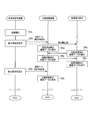
図12は、本変形例に係る超音波診断システムの動作フローの一例を示す図である。ここで、図12では、同じ被検体に係る超音波画像に対して、2回目の静止画保存操作が行われた場合のステップS7aの超音波診断装置1の動作のみが、図5の場合と異なっている。具体的には、当該静止画保存操作が行われた場合、超音波診断装置1は、画像管理装置4に対して格納指示信号を送信するものの、画像表示装置2に対しては表示指示信号を送信しない態様となっている。尚、その他の各ステップS1a~S7a、S8a~S9aの動作は、図5の各ステップS1~S7等の動作と同様であるから、ここでの説明は、省略する。
このような機能を実現するため、超音波診断装置1は、設定データとして、表示指示信号を送信するか否かを判定するための条件設定、表示指示信号を送信するタイミングを規定するための設定に関するデータを含むものとする。超音波診断装置1の制御部11は、当該設定データに基づいて、表示指示信号の出力態様を決定する。
例えば、超音波診断装置1は、当該設定データに基づいて、表示指示信号を送信するか否かを判定し、静止画保存操作の回数が所定回数以上の場合には、表示指示信号を送信しないようにしたり、動画データを保存する操作の場合には、表示指示信号を送信しないようにしたりする。この場合、超音波診断装置1の制御部11は、同じ被検体に係る超音波画像に対する静止画保存操作の回数を記憶部17に格納し、静止画保存操作がなされる毎に当該回数をインクリメントしていく構成とすればよい。
そうすることで、画像表示装置2の超音波画像閲覧画面が一の超音波画像しか表示できない場合等において、超音波画像を保存する毎に、超音波画像閲覧画面に表示される超音波画像が頻繁に入れ替わることを防止することができる。言い換えると、医師等は、最初に取得した超音波画像を見て診察を行うことが可能となる。
又、超音波診断装置1は、保存対象の画像データの画像種別に基づいて、表示指示信号を送信する際のタイミングを決定することができる。例えば、画像表示装置2に対して動画データ等を表示させる場合には、超音波診断装置1は、画像管理装置4に格納指示信号を送信するタイミングから、表示指示信号を出力するタイミングを一定時間遅らせるように設定することができる。画像管理装置4に動画データを格納する場合、データ量が大きいため、超音波診断装置1が、画像管理装置4に対して格納指示信号を送信してから、画像管理装置4に動画データが格納完了するまでに、一定時間を有するおそれがある。従って、超音波診断装置1が画像管理装置4に格納指示信号を送信するタイミングから、表示指示信号を送信するタイミングを一定時間遅らせることによって、画像表示装置2においては、画像管理装置4に対して画像データ要求信号を送信してから、画像管理装置4から対応する画像データを取得するまでの待機時間を減らすことができる。
(その他の実施形態)
本発明は、上記実施形態に限らず、種々に変形態様が考えられる。
本発明は、上記実施形態に限らず、種々に変形態様が考えられる。
上記実施形態では、超音波診断装置1が超音波画像データに付帯させる「識別情報」の一例として、画像IDを示したが、超音波画像データを識別可能な情報であれば必ずしも画像IDである必要はなく、診察の順番を示す診察ID等であってもよい。そして、同じ被検体に対しては、同じ診察IDを用いて、複数の超音波画像データを保存する際には、画像管理装置4と画像表示装置2は、診察IDと超音波診断装置1からの指示信号の受信時刻に基づいて、複数の超音波画像データを識別する構成としてもよい。
又、上記実施形態では、「保存指示信号」が生成されるタイミングの一例として、医師等が超音波画像の静止画を保存する操作を行ったタイミングを示したが、超音波診断装置1に超音波画像データを画像管理装置4に保存させるための操作等であれば、その態様は種々変形し得る。例えば、スキャン開始操作を必要とするものであれば、スキャン開始操作が行われた場合、一定間隔毎に、保存指示信号が生成されるようなものであってもよい。又、動画の超音波画像データを画像表示装置2に表示させる場合であれば、動画保存終了操作がなされたタイミングであってもよい。
又、上記実施形態では、超音波診断システムの構成の一例として、画像表示装置2と電子カルテ端末3とを別体の装置とする態様を示したが、画像表示装置2と電子カルテ端末3とが一体として構成されていてもよい。言い換えると、画像表示装置2として、電子カルテ端末3の機能プログラムを有するものを用いてもよい。
以上、本発明の具体例を詳細に説明したが、これらは例示にすぎず、請求の範囲を限定するものではない。請求の範囲に記載の技術には、以上に例示した具体例を様々に変形、変更したものが含まれる。
本明細書および添付図面の記載により、少なくとも以下の事項が明らかとなる。
被検体の検査対象部位を撮像した超音波画像を表示する画像表示装置2、及び当該超音波画像の画像データを管理する画像管理装置4と通信可能に構成された超音波診断装置1であって、操作者の操作入力を受け付ける入力部16と、前記操作入力に基づいて生成される保存指示信号に応じて、前記画像管理装置4に対して、前記超音波画像の画像データを識別情報とともに送信して当該画像データを当該識別情報と関連付けて格納させ、且つ、前記画像表示装置2に対して、前記識別情報とともに、前記超音波画像の画像データを表示させるための表示指示信号を送信して、前記超音波画像の画像データを前記画像管理装置4から取得させる制御部11と、を備えることを特徴とする超音波診断装置1を開示する。
ここで、前記識別情報は、前記制御部11によって生成されるものであってもよい。
又、ここで、前記制御部11は、同じ被検体に係る前記保存指示信号の指示回数が所定の回数以上の場合、前記画像表示装置2に対して、前記表示指示信号を送信しないものであってもよい。
又、ここで、前記制御部11は、前記画像データの画像種別に基づいて、前記表示指示信号を送信するタイミングを決定するものであってもよい。
又、ここで、前記保存指示信号は、前記超音波画像の静止画を保存する操作の入力に応じて生成されるものであってもよい。
又、被検体の検査対象部位を撮像した超音波画像を表示する画像表示装置2、及び当該超音波画像の画像データを管理する画像管理装置4と通信可能にされた超音波診断装置1に実行させる超音波診断プログラムであって、操作者の操作入力を受け付ける処理と、前記操作入力に基づいて生成される保存指示信号に応じて、前記画像管理装置4に対して、前記超音波画像の画像データを識別情報とともに送信して当該画像データを当該識別情報と関連付けて格納させ、前記画像表示装置2に対して、前記識別情報とともに、前記超音波画像の画像データを表示させるための表示指示信号を送信して、前記超音波画像の画像データを前記画像管理装置4から取得させる処理を備えることを特徴とする超音波診断プログラムを開示する。
2016年3月28日出願の特願2016-063517の日本出願に含まれる明細書、図面および要約書の開示内容は、すべて本願に援用される。
本開示は、医用診断システムの医用診断装置として好適に用いることができる。
1 超音波診断装置
2 画像表示装置
3 電子カルテ端末
4 画像管理装置
5 電子カルテ管理装置
6 通信回線
2 画像表示装置
3 電子カルテ端末
4 画像管理装置
5 電子カルテ管理装置
6 通信回線
Claims (7)
- 被検体の検査対象部位を撮像した医用画像を表示する画像表示装置、及び当該医用画像の画像データを管理する画像管理装置と通信可能に構成された医用診断装置であって、
操作者の操作入力を受け付ける入力部と、
前記操作入力に基づいて生成される保存指示信号に応じて、
前記画像管理装置に対して、前記医用画像の画像データを識別情報とともに送信して当該画像データを当該識別情報と関連付けて格納させ、
且つ、前記画像表示装置に対して、前記識別情報とともに、前記医用画像の画像データを表示させるための表示指示信号を送信して、前記医用画像の画像データを前記画像管理装置から取得させる制御部と、
を備えることを特徴とする医用診断装置。 - 前記識別情報は、前記制御部によって生成される
ことを特徴とする請求項1に記載の医用診断装置。 - 前記制御部は、同じ被検体に係る前記保存指示信号の回数が所定の回数以上の場合、前記画像表示装置に対して、前記表示指示信号を送信しない
ことを特徴とする請求項1に記載の医用診断装置。 - 前記制御部は、前記画像データの画像種別に基づいて、前記表示指示信号を送信するタイミングを決定する
ことを特徴とする請求項1に記載の医用診断装置。 - 前記保存指示信号は、前記医用画像の静止画を保存する操作の入力に応じて生成される
ことを特徴とする請求項1に記載の医用診断装置。 - 前記医用画像として超音波画像を生成する超音波診断装置に適用された
ことを特徴とする請求項1に記載の医用診断装置。 - 被検体の検査対象部位を撮像した医用画像を表示する画像表示装置、及び当該医用画像の画像データを管理する画像管理装置と通信可能に構成された医用診断装置に実行させる超音波診断プログラムであって、
操作者の操作入力を受け付ける処理と、
前記操作入力に基づいて生成される保存指示信号に応じて、
前記画像管理装置に対して、前記医用画像の画像データを識別情報とともに送信して当該画像データを当該識別情報と関連付けて格納させ、
且つ、前記画像表示装置に対して、前記識別情報とともに、前記医用画像の画像データを表示させるための表示指示信号を送信して、前記医用画像の画像データを前記画像管理装置から取得させる処理と、
を備えることを特徴とする医用診断プログラム。
Priority Applications (2)
| Application Number | Priority Date | Filing Date | Title |
|---|---|---|---|
| US16/086,919 US20190103183A1 (en) | 2016-03-28 | 2017-03-23 | Medical diagnostic device and medical diagnostic program |
| JP2018509152A JP6658870B2 (ja) | 2016-03-28 | 2017-03-23 | 医用診断装置、及び医用診断プログラム |
Applications Claiming Priority (2)
| Application Number | Priority Date | Filing Date | Title |
|---|---|---|---|
| JP2016-063517 | 2016-03-28 | ||
| JP2016063517 | 2016-03-28 |
Publications (1)
| Publication Number | Publication Date |
|---|---|
| WO2017170085A1 true WO2017170085A1 (ja) | 2017-10-05 |
Family
ID=59964467
Family Applications (1)
| Application Number | Title | Priority Date | Filing Date |
|---|---|---|---|
| PCT/JP2017/011603 Ceased WO2017170085A1 (ja) | 2016-03-28 | 2017-03-23 | 医用診断装置、及び医用診断プログラム |
Country Status (3)
| Country | Link |
|---|---|
| US (1) | US20190103183A1 (ja) |
| JP (1) | JP6658870B2 (ja) |
| WO (1) | WO2017170085A1 (ja) |
Cited By (1)
| Publication number | Priority date | Publication date | Assignee | Title |
|---|---|---|---|---|
| WO2021157405A1 (ja) * | 2020-02-04 | 2021-08-12 | ソニーグループ株式会社 | 解析装置、解析方法、解析プログラム及び診断支援システム |
Citations (2)
| Publication number | Priority date | Publication date | Assignee | Title |
|---|---|---|---|---|
| JP2012217593A (ja) * | 2011-04-08 | 2012-11-12 | Konica Minolta Medical & Graphic Inc | 超音波診断装置及び医用画像管理システム |
| JP2014150804A (ja) * | 2013-02-05 | 2014-08-25 | Konica Minolta Inc | 超音波画像診断装置 |
Family Cites Families (1)
| Publication number | Priority date | Publication date | Assignee | Title |
|---|---|---|---|---|
| US20130321286A1 (en) * | 2012-05-31 | 2013-12-05 | Mindray Ds Usa, Inc. | Systems and methods for interfacing with an ultrasound system |
-
2017
- 2017-03-23 JP JP2018509152A patent/JP6658870B2/ja active Active
- 2017-03-23 WO PCT/JP2017/011603 patent/WO2017170085A1/ja not_active Ceased
- 2017-03-23 US US16/086,919 patent/US20190103183A1/en not_active Abandoned
Patent Citations (2)
| Publication number | Priority date | Publication date | Assignee | Title |
|---|---|---|---|---|
| JP2012217593A (ja) * | 2011-04-08 | 2012-11-12 | Konica Minolta Medical & Graphic Inc | 超音波診断装置及び医用画像管理システム |
| JP2014150804A (ja) * | 2013-02-05 | 2014-08-25 | Konica Minolta Inc | 超音波画像診断装置 |
Cited By (1)
| Publication number | Priority date | Publication date | Assignee | Title |
|---|---|---|---|---|
| WO2021157405A1 (ja) * | 2020-02-04 | 2021-08-12 | ソニーグループ株式会社 | 解析装置、解析方法、解析プログラム及び診断支援システム |
Also Published As
| Publication number | Publication date |
|---|---|
| US20190103183A1 (en) | 2019-04-04 |
| JPWO2017170085A1 (ja) | 2019-02-07 |
| JP6658870B2 (ja) | 2020-03-04 |
Similar Documents
| Publication | Publication Date | Title |
|---|---|---|
| JP6683677B2 (ja) | 自家診断及び遠隔診断のための超音波診断装置、並びに超音波診断装置の動作方法 | |
| JP6284439B2 (ja) | 医療情報処理システム | |
| US11759180B2 (en) | Medical system and medical information transfer method | |
| JP2011255165A (ja) | 画像診断装置、超音波診断装置及び医用画像表示装置 | |
| US10609322B2 (en) | Medical diagnostic apparatus and medical diagnostic system | |
| JP6663027B2 (ja) | 超音波診断システム及び超音波診断システムの制御方法 | |
| CN103279632B (zh) | 具有用于图像采集的控制模块的诊断系统 | |
| JP2014018440A (ja) | 医用画像生成装置及び医用画像管理システム | |
| JP2002253552A (ja) | リモート閲覧用ステーションにおいて画像及びリポートを結合する方法及び装置 | |
| JP2012176000A (ja) | 超音波診断装置、医用画像管理システム及びプログラム | |
| JP6658870B2 (ja) | 医用診断装置、及び医用診断プログラム | |
| CN114639466A (zh) | 远程超声会诊方法、系统及电子设备 | |
| JP2015229069A (ja) | 超音波画像診断装置及び超音波画像診断装置の操作支援装置 | |
| JP5349102B2 (ja) | 超音波画像処理表示装置、超音波画像処理表示方法及び制御処理プログラム | |
| WO2022064851A1 (ja) | 超音波システムおよび超音波システムの制御方法 | |
| JP2009106494A (ja) | 超音波診断装置、及びアノテーション表示装置 | |
| JP2024106433A (ja) | 超音波情報処理装置、超音波診断システムおよび超音波診断装置 | |
| JP4650045B2 (ja) | 超音波診断システム | |
| JP2017182244A (ja) | 医療情報提供システム | |
| JP6680046B2 (ja) | 超音波診断装置、及び超音波診断プログラム | |
| JP2012217593A (ja) | 超音波診断装置及び医用画像管理システム | |
| KR20130125742A (ko) | 프로브 장치, 서버, 초음파 영상 진단 시스템, 및 초음파 영상 처리 방법 | |
| JP4649195B2 (ja) | 検査管理システム | |
| US20190328358A1 (en) | Ultrasonic diagnostic apparatus, and medical data processing apparatus | |
| JP2015198807A (ja) | 超音波画像診断装置及びプログラム |
Legal Events
| Date | Code | Title | Description |
|---|---|---|---|
| WWE | Wipo information: entry into national phase |
Ref document number: 2018509152 Country of ref document: JP |
|
| NENP | Non-entry into the national phase |
Ref country code: DE |
|
| 121 | Ep: the epo has been informed by wipo that ep was designated in this application |
Ref document number: 17774626 Country of ref document: EP Kind code of ref document: A1 |
|
| 122 | Ep: pct application non-entry in european phase |
Ref document number: 17774626 Country of ref document: EP Kind code of ref document: A1 |