WO2017169720A1 - Dispositif et procédé de lecture, dispositif et procédé de génération de fichier - Google Patents
Dispositif et procédé de lecture, dispositif et procédé de génération de fichier Download PDFInfo
- Publication number
- WO2017169720A1 WO2017169720A1 PCT/JP2017/010104 JP2017010104W WO2017169720A1 WO 2017169720 A1 WO2017169720 A1 WO 2017169720A1 JP 2017010104 W JP2017010104 W JP 2017010104W WO 2017169720 A1 WO2017169720 A1 WO 2017169720A1
- Authority
- WO
- WIPO (PCT)
- Prior art keywords
- file
- audio stream
- audio
- stream
- unit
- Prior art date
Links
Images


Classifications
-
- G—PHYSICS
- G10—MUSICAL INSTRUMENTS; ACOUSTICS
- G10L—SPEECH ANALYSIS OR SYNTHESIS; SPEECH RECOGNITION; SPEECH OR VOICE PROCESSING; SPEECH OR AUDIO CODING OR DECODING
- G10L19/00—Speech or audio signals analysis-synthesis techniques for redundancy reduction, e.g. in vocoders; Coding or decoding of speech or audio signals, using source filter models or psychoacoustic analysis
- G10L19/04—Speech or audio signals analysis-synthesis techniques for redundancy reduction, e.g. in vocoders; Coding or decoding of speech or audio signals, using source filter models or psychoacoustic analysis using predictive techniques
- G10L19/16—Vocoder architecture
- G10L19/167—Audio streaming, i.e. formatting and decoding of an encoded audio signal representation into a data stream for transmission or storage purposes
-
- G—PHYSICS
- G06—COMPUTING; CALCULATING OR COUNTING
- G06F—ELECTRIC DIGITAL DATA PROCESSING
- G06F13/00—Interconnection of, or transfer of information or other signals between, memories, input/output devices or central processing units
-
- G—PHYSICS
- G10—MUSICAL INSTRUMENTS; ACOUSTICS
- G10L—SPEECH ANALYSIS OR SYNTHESIS; SPEECH RECOGNITION; SPEECH OR VOICE PROCESSING; SPEECH OR AUDIO CODING OR DECODING
- G10L19/00—Speech or audio signals analysis-synthesis techniques for redundancy reduction, e.g. in vocoders; Coding or decoding of speech or audio signals, using source filter models or psychoacoustic analysis
- G10L19/008—Multichannel audio signal coding or decoding using interchannel correlation to reduce redundancy, e.g. joint-stereo, intensity-coding or matrixing
-
- H—ELECTRICITY
- H04—ELECTRIC COMMUNICATION TECHNIQUE
- H04N—PICTORIAL COMMUNICATION, e.g. TELEVISION
- H04N21/00—Selective content distribution, e.g. interactive television or video on demand [VOD]
- H04N21/20—Servers specifically adapted for the distribution of content, e.g. VOD servers; Operations thereof
- H04N21/23—Processing of content or additional data; Elementary server operations; Server middleware
- H04N21/233—Processing of audio elementary streams
- H04N21/2335—Processing of audio elementary streams involving reformatting operations of audio signals, e.g. by converting from one coding standard to another
-
- H—ELECTRICITY
- H04—ELECTRIC COMMUNICATION TECHNIQUE
- H04N—PICTORIAL COMMUNICATION, e.g. TELEVISION
- H04N21/00—Selective content distribution, e.g. interactive television or video on demand [VOD]
- H04N21/20—Servers specifically adapted for the distribution of content, e.g. VOD servers; Operations thereof
- H04N21/23—Processing of content or additional data; Elementary server operations; Server middleware
- H04N21/234—Processing of video elementary streams, e.g. splicing of video streams, manipulating MPEG-4 scene graphs
- H04N21/2343—Processing of video elementary streams, e.g. splicing of video streams, manipulating MPEG-4 scene graphs involving reformatting operations of video signals for distribution or compliance with end-user requests or end-user device requirements
- H04N21/23439—Processing of video elementary streams, e.g. splicing of video streams, manipulating MPEG-4 scene graphs involving reformatting operations of video signals for distribution or compliance with end-user requests or end-user device requirements for generating different versions
-
- H—ELECTRICITY
- H04—ELECTRIC COMMUNICATION TECHNIQUE
- H04N—PICTORIAL COMMUNICATION, e.g. TELEVISION
- H04N21/00—Selective content distribution, e.g. interactive television or video on demand [VOD]
- H04N21/20—Servers specifically adapted for the distribution of content, e.g. VOD servers; Operations thereof
- H04N21/25—Management operations performed by the server for facilitating the content distribution or administrating data related to end-users or client devices, e.g. end-user or client device authentication, learning user preferences for recommending movies
- H04N21/266—Channel or content management, e.g. generation and management of keys and entitlement messages in a conditional access system, merging a VOD unicast channel into a multicast channel
- H04N21/2662—Controlling the complexity of the video stream, e.g. by scaling the resolution or bitrate of the video stream based on the client capabilities
-
- H—ELECTRICITY
- H04—ELECTRIC COMMUNICATION TECHNIQUE
- H04N—PICTORIAL COMMUNICATION, e.g. TELEVISION
- H04N21/00—Selective content distribution, e.g. interactive television or video on demand [VOD]
- H04N21/40—Client devices specifically adapted for the reception of or interaction with content, e.g. set-top-box [STB]; Operations thereof
- H04N21/43—Processing of content or additional data, e.g. demultiplexing additional data from a digital video stream; Elementary client operations, e.g. monitoring of home network or synchronising decoder's clock; Client middleware
- H04N21/439—Processing of audio elementary streams
-
- H—ELECTRICITY
- H04—ELECTRIC COMMUNICATION TECHNIQUE
- H04N—PICTORIAL COMMUNICATION, e.g. TELEVISION
- H04N21/00—Selective content distribution, e.g. interactive television or video on demand [VOD]
- H04N21/80—Generation or processing of content or additional data by content creator independently of the distribution process; Content per se
- H04N21/83—Generation or processing of protective or descriptive data associated with content; Content structuring
- H04N21/845—Structuring of content, e.g. decomposing content into time segments
- H04N21/8456—Structuring of content, e.g. decomposing content into time segments by decomposing the content in the time domain, e.g. in time segments
-
- H—ELECTRICITY
- H04—ELECTRIC COMMUNICATION TECHNIQUE
- H04N—PICTORIAL COMMUNICATION, e.g. TELEVISION
- H04N21/00—Selective content distribution, e.g. interactive television or video on demand [VOD]
- H04N21/80—Generation or processing of content or additional data by content creator independently of the distribution process; Content per se
- H04N21/85—Assembly of content; Generation of multimedia applications
- H04N21/854—Content authoring
- H04N21/8543—Content authoring using a description language, e.g. Multimedia and Hypermedia information coding Expert Group [MHEG], eXtensible Markup Language [XML]
-
- G—PHYSICS
- G10—MUSICAL INSTRUMENTS; ACOUSTICS
- G10L—SPEECH ANALYSIS OR SYNTHESIS; SPEECH RECOGNITION; SPEECH OR VOICE PROCESSING; SPEECH OR AUDIO CODING OR DECODING
- G10L19/00—Speech or audio signals analysis-synthesis techniques for redundancy reduction, e.g. in vocoders; Coding or decoding of speech or audio signals, using source filter models or psychoacoustic analysis
- G10L19/0017—Lossless audio signal coding; Perfect reconstruction of coded audio signal by transmission of coding error
Definitions
- the present disclosure relates to a playback device and a playback method, and a file generation device and a file generation method, and in particular, acquires a video stream having an optimal bit rate when acquiring an audio stream and a video stream encoded by a lossless compression method.
- the present invention relates to a playback device and a playback method, a file generation device, and a file generation method.
- MPEG-DASH Moving / Picture / Experts / Group / phase / Dynamic / Adaptive / Streaming / over / HTTP
- OTT-V Over The Top Video
- MPEG-DASH Moving / Picture / Experts / Group / phase / Dynamic / Adaptive / Streaming / over / HTTP
- a distribution server prepares video data groups with different bit rates for a single video content, and a playback terminal requests a video data group with an optimal bit rate according to the condition of the transmission path.
- Adaptive streaming delivery is realized.
- an encoding method capable of predicting a bit rate in advance is assumed as an encoding method for moving image content.
- audio digital signals that have been A / D (Analog / Digital) converted by the PCM (Pulse Code Modulation) method as an audio stream encoding method will not cause underflow or overflow in a fixed-size buffer.
- An irreversible compression method that is encoded in the above is assumed. Therefore, the bit rate of the moving image content to be acquired is determined based on the predicted bit rate of the moving image content and the network bandwidth.
- a high-resolution audio A / D conversion method includes a DSD (Direct Stream Digital) method.
- the DSD method is a method employed as a Super Audio CD (SA-CD) recording / reproducing method, and is a method based on 1-bit digital sigma modulation.
- SA-CD Super Audio CD
- audio analog signal information is expressed by the density of change points of “1” and “0” using a time axis. Therefore, high-resolution recording / reproduction independent of the number of bits can be realized.
- the pattern of “1” and “0” of the audio digital signal changes according to the waveform of the audio analog signal. Therefore, in lossless DSD method, which performs lossless compression coding of audio digital signals that have been A / D converted by the DSD method based on the patterns of “1” and “0”, the audio after encoding according to the waveform of the audio analog signal The bit generation amount of the digital signal varies. Therefore, it is difficult to predict the bit rate in advance.
- MPEG-DASH Dynamic-Adaptive-Streaming-over-HTTP
- URL http://mpeg.chiariglione.org/standards/mpeg-dash/media-presentation-description-and-segment-formats/text-isoiec-23009-12012-dam -1)
- the network bandwidth and the audio stream bit rate are used. Based on the maximum value to be obtained, the bit rate of the video stream to be obtained must be selected. Therefore, it is difficult to obtain a video stream with an optimal bit rate.
- the present disclosure has been made in view of such a situation, and when acquiring an audio stream and a video stream encoded by a lossless compression method, a video stream having an optimum bit rate can be acquired. To do.
- the playback device includes an acquisition unit that acquires an audio stream encoded by a lossless compression method before a video stream corresponding to the audio stream and detects a bit rate of the audio stream. And a selection unit that selects the video stream to be acquired from the plurality of video streams having different bit rates based on the bit rate detected by the acquisition unit.
- the playback method according to the first aspect of the present disclosure corresponds to the playback device according to the first aspect of the present disclosure.
- an audio stream encoded by a lossless compression method is acquired before a video stream corresponding to the audio stream, and a bit rate of the audio stream is detected, and the detected audio stream is detected. Based on the bit rate, the video stream to be acquired is selected from the plurality of video streams having different bit rates.
- a file generation device is a management file that manages an audio stream encoded by a lossless compression method and a video stream corresponding to the audio stream, the encoding method of the audio stream
- the file generation apparatus includes a file generation unit that generates a management file including information indicating that the buffer is not encoded with a fixed size buffer so that underflow or overflow does not occur.
- the file generation method according to the second aspect of the present disclosure corresponds to the file generation apparatus according to the second aspect of the present disclosure.
- the management file manages an audio stream encoded by a lossless compression method and a video stream corresponding to the audio stream, and the encoding method of the audio stream is fixed.
- a management file is generated that includes information indicating that the size of the buffer is not a system that is encoded so that underflow or overflow does not occur.
- the playback device according to the first aspect and the file generation device according to the second aspect can be realized by causing a computer to execute a program.
- a program to be executed by a computer is transmitted through a transmission medium or recorded on a recording medium, Can be provided.
- a video stream having an optimal bit rate can be acquired.
- a management file can be generated.
- a management file that enables acquisition of a video stream having an optimal bit rate is generated. Can do.
- First embodiment Information processing system (FIGS. 1 to 9) 2.
- Second embodiment Information processing system (FIGS. 10 to 14) 3.
- Third embodiment Information processing system (FIGS. 15 to 17) 4).
- Fourth embodiment Information processing system (FIGS. 18 and 19) 5.
- Fifth embodiment Information processing system (FIG. 20) 6).
- Sixth embodiment information processing system (FIG. 21) 7).
- Seventh embodiment Information processing system (FIGS. 22 to 24) 8).
- Explanation of losslessDSD method (Figs. 25 to 28) 9.
- Eighth Embodiment Computer (FIG. 29)
- FIG. 1 is a diagram illustrating an overview of an information processing system according to the first embodiment to which the present disclosure is applied.
- the information processing system 10 in FIG. 1 is configured by connecting a Web server 12 as a DASH server connected to a file generation device 11 and a moving image playback terminal 14 as a DASH client via the Internet 13.
- the Web server 12 performs live distribution of the moving image content file generated by the file generation device 11 to the moving image playback terminal 14 in accordance with MPEG-DASH.
- the file generation device 11 performs A / D conversion on the video analog signal and audio analog signal of the moving image content to generate a video digital signal and an audio digital signal. Then, the file generation device 11 encodes a signal such as a video digital signal or an audio digital signal of the moving image content at a plurality of bit rates by a predetermined encoding method, and generates an encoded stream.
- the audio digital signal encoding method is a lossless DSD method or an MPEG-4 (MovingMoPicture Experts Group phase 4) method.
- the MPEG-4 system is a system for irreversibly compressing audio digital signals that have been A / D converted by the PCM system so that underflow or overflow does not occur in a fixed-size buffer.
- the file generation device 11 converts the generated encoded stream into a file in units of time from several seconds to about 10 seconds called segments.
- the file generation device 11 uploads the segment file generated as a result to the Web server 12.
- the file generation device 11 also generates an MPD (Media Presentation Description) file (management file) for managing moving image content.
- the file generation device 11 uploads the MPD file to the Web server 12.
- the Web server 12 stores the segment file and MPD file uploaded from the file generation device 11.
- the web server 12 transmits the stored segment file or MPD file to the video playback terminal 14 in response to a request from the video playback terminal 14.
- the video playback terminal 14 includes streaming data control software (hereinafter referred to as control software) 21, video playback software 22, and client software (hereinafter referred to as HTTP (HyperText Transfer Protocol) access). 23) (referred to as access software).
- control software streaming data control software
- video playback software video playback software 22
- client software hereinafter referred to as HTTP (HyperText Transfer Protocol) access. 23
- the control software 21 is software that controls data streamed from the Web server 12. Specifically, the control software 21 causes the video playback terminal 14 to acquire an MPD file from the Web server 12.
- control software 21 uses the MPD file, the reproduction time information indicating the reproduction time specified by the moving image reproduction software 22, and the network stream of the Internet 13, and the encoded stream of the segment file to be reproduced.
- a transmission request is commanded to the access software 23.
- the moving image reproduction software 22 is software for reproducing the encoded stream acquired from the Web server 12 via the Internet 13. Specifically, the moving image playback software 22 designates playback time information to the control software 21. Also, the moving image playback software 22 decodes the encoded stream received by the moving image playback terminal 14 when receiving a notification of reception start from the access software 23. The moving image reproduction software 22 outputs a video digital signal and an audio digital signal obtained as a result of decoding.
- the access software 23 is software that controls communication with the Web server 12 via the Internet 13 using HTTP. Specifically, the access software 23 causes the moving image playback terminal 14 to transmit a transmission request for the encoded stream of the segment file to be played back in response to a command from the control software 21. In response to the transmission request, the access software 23 causes the video playback terminal 14 to start receiving the encoded stream transmitted from the Web server 12 and supplies the video playback software 22 with a reception start notification. To do.
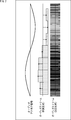
- FIG. 2 is a diagram for explaining the DSD method.
- the horizontal axis represents time
- the vertical axis represents the value of each signal.
- the waveform of the audio analog signal is a sine wave.
- the value of the audio analog signal at each sampling time is converted into an audio digital signal of a fixed number of bits corresponding to the value. Is done.
- the audio analog signal value at each sampling time is an audio having a density of change points of “0” and “1” corresponding to the value. Converted to a digital signal. Specifically, the larger the value of the audio analog signal, the higher the density of the changing points of the audio digital signal, and the smaller the value of the audio analog signal, the lower the density of the changing points of the audio digital signal. That is, the pattern of “0” and “1” of the audio digital signal changes according to the value of the audio analog signal.
- bit generation amount of the encoded stream obtained by encoding this audio digital signal by the lossless DSD method that performs lossless compression encoding based on the pattern of “0” and “1” depends on the waveform of the audio analog signal. fluctuate. Therefore, it is difficult to predict the bit rate in advance.
- FIG. 3 is a block diagram illustrating a configuration example of the file generation device in FIG.
- 3 includes an acquisition unit 31, an encoding unit 32, a segment file generation unit 33, an MPD file generation unit 34, and an upload unit 35.
- the acquisition unit 31 of the file generation device 11 acquires a video analog signal or an audio analog signal of moving image content and performs A / D conversion.
- the acquisition unit 31 supplies the encoding unit 32 with signals such as a video digital signal and an audio digital signal obtained as a result of A / D conversion, and other acquired moving image content signals.
- the encoding unit 32 encodes the moving image content signals supplied from the acquisition unit 31 at a plurality of bit rates, respectively, to generate an encoded stream.
- the encoding unit 32 supplies the generated encoded stream to the segment file generation unit 33.
- the segment file generation unit 33 (generation unit) converts the encoded stream supplied from the encoding unit 32 into a file on a segment basis for each bit rate.
- the segment file generation unit 33 supplies the segment file generated as a result to the upload unit 35.
- the MPD file generation unit 34 includes information indicating that the encoding method of the audio digital signal is the lossless DSD method, the maximum bit rate of the audio stream that is the encoded stream of the audio digital signal, and the encoded stream of the video digital signal. Generate an MPD file containing the bit rate of a video stream. The maximum bit rate is the maximum value that can be taken as the bit rate.
- the MPD file generation unit 34 supplies the MPD file to the upload unit 35.
- the upload unit 35 uploads the segment file supplied from the segment file generation unit 33 and the MPD file supplied from the MPD file generation unit 34 to the Web server 12 of FIG.
- FIG. 4 is a diagram illustrating a first description example of the MPD file.
- FIG. 4 for the convenience of explanation, only the description for managing the segment file of the audio stream is shown in the description of the MPD file. The same applies to FIGS. 5, 10, 11, 22, and 23 described later.
- information such as video content encoding method, bit rate, image size, audio language, etc. are layered and described in XML format.
- the MPD file hierarchically includes elements such as a period, an adaptation set, an representation, a segment info, and the like.
- the video content managed by the user is divided in a predetermined time range (for example, a unit such as a program or CM (Commercial)).
- the period element is described for each divided moving image content.
- the period element has information common to the corresponding moving image content, such as the reproduction start time of the moving image content, the URL (Uniform ResourceatorLocator) of the Web server 12 that stores the segment file of the moving image content, and MinBufferTime.
- MinBufferTime is information indicating the buffer time of the virtual buffer, and is set to 0 in the example of FIG.
- the adaptation set element is included in the period element, and groups the representation elements corresponding to the segment file group of the same encoded stream of the moving image content corresponding to the period element.
- the representation elements are grouped according to the data type of the corresponding segment file group, for example. In the example of FIG. 4, three representation elements corresponding to each of segment files of three types of audio streams having different bit rates are grouped by one adaptation set element.
- the adaptation set element includes information such as media type, language, subtitles, dubbing, maxBandwidth which is the maximum value of the bit rate, MinBandwidth which is the minimum value, and the like as information common to the corresponding group of segment files.
- the adaptation set element has a SegmentTemplate that indicates the rule of the segment length and the file name of the segment file.
- SegmentTemplate timescale, duration, initialization, and media are described.
- Timescale is a value representing 1 second
- duration is a segment length value when the timescale is 1 second.
- the timescale is 44100 and the duration is 88200. Therefore, the segment length is 2 seconds.
- Initialization is information indicating a rule for the name of the initialization segment file among the segment files of the audio stream.
- initialization is “$ Bandwidth $ init.mp4”. Therefore, the name of the initialization segment file of the audio stream is obtained by adding init to the Bandwidth of the representation element.
- media is information indicating a rule for the name of the media segment file among the segment files of the audio stream.
- media is “$ Bandwidth $-$ Number $ .mp4”. Therefore, the name of the media segment file of the audio stream is obtained by adding “-” to the Bandwidth of the representation element and sequentially adding numbers.
- the representation element is included in the adaptation set element that groups the representation elements, and is described for each segment file group of the same encoded stream of the moving image content corresponding to the upper layer period element.
- the representation element has a band width indicating a bit rate, an image size, and the like as information common to the corresponding segment file group.
- the representation element corresponding to the audio stream describes the maximum bit rate of the audio stream as a bit rate common to the corresponding segment file group.
- the maximum bit rates of the three types of audio streams are 2.8 Mbps, 5.6 Mbps, and 11.2 Mbps. Accordingly, the band widths of the three representation elements are 2.800000, 5600000, and 11200000, respectively. Further, the MinBandwidth of the adaptation set element is 280,000 and maxBandwidth is 11200000.
- the segment info element is included in the representation element and has information on each segment file of the segment file group corresponding to the representation element.
- the moving image playback terminal 14 can perform playback without interruption by acquiring the audio stream and the video stream on the assumption that the bit rate of the audio stream is the maximum bit rate. However, if the actual bit rate of the audio stream is smaller than the maximum bit rate, the bandwidth allocated to the audio stream is wasted.
- FIG. 5 is a diagram illustrating a second description example of the MPD file.
- the encoding method of two types of audio streams out of three types of audio streams having different bit rates is the lossless DSD method, and the encoding method of one type of audio stream is the MPEG-4 method. .
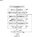
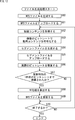
- FIG. 6 is a flowchart for explaining file generation processing of the file generation apparatus 11 of FIG.
- the MPD file generation unit 34 of the file generation device 11 generates an MPD file and supplies the MPD file to the upload unit 35.
- the upload unit 35 uploads the MPD file supplied from the MPD file generation unit 34 to the Web server 12.
- step S12 the acquisition unit 31 acquires the video analog signal and audio analog signal of the moving image content in segment units, and performs A / D conversion.
- the acquisition unit 31 supplies the encoding unit 32 with signals such as video digital signals and audio analog signals obtained as a result of A / D conversion, and other segment-unit moving image content signals.
- step S13 the encoding unit 32 encodes the moving image content signal supplied from the acquisition unit 31 at a plurality of bit rates by a predetermined encoding method to generate an encoded stream.
- the encoding unit 32 supplies the generated encoded stream to the segment file generation unit 33.
- step S14 the segment file generation unit 33 converts the encoded stream supplied from the encoding unit 32 into a file for each bit rate, and generates a segment file.
- the segment file generation unit 33 supplies the generated segment file to the upload unit 35.
- step S15 the upload unit 35 uploads the segment file supplied from the segment file generation unit 33 to the Web server 12.
- step S16 the acquisition unit 31 determines whether to end the file generation process. Specifically, the acquisition unit 31 determines that the file generation process is not terminated when a new segment content video content signal is supplied. Then, the process returns to step S12, and the processes of steps S12 to S16 are repeated until it is determined that the file generation process is finished.
- the acquisition part 31 determines with complete
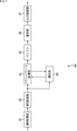
- FIG. 7 is a block diagram showing an example of the configuration of a streaming playback unit realized by executing the control software 21, the video playback software 22, and the access software 23 by the video playback terminal 14 of FIG. .
- the streaming playback unit 60 includes an MPD acquisition unit 61, an MPD processing unit 62, a segment file acquisition unit 63, a selection unit 64, a buffer 65, a decoding unit 66, and an output control unit 67.
- the MPD acquisition unit 61 of the streaming playback unit 60 requests and acquires the MPD file from the Web server 12.
- the MPD acquisition unit 61 supplies the acquired MPD file to the MPD processing unit 62.
- the MPD processing unit 62 analyzes the MPD file supplied from the MPD acquisition unit 61. Specifically, the MPD processing unit 62 acquires acquisition information such as the bandwidth of each encoded stream, the URL of a segment file that stores each encoded stream, and the file name.
- the segment file acquisition unit 63 When the segment file acquisition unit 63 indicates that at least one of the encoding method information of each audio stream is not a fixed method, the segment file acquisition unit 63 extracts audio streams having different band widths based on the network bandwidth of the Internet 13 and the band width of each audio stream. Select the audio stream to be acquired. Then, the segment file acquisition unit 63 (acquisition unit) transmits the acquisition information of the segment file at the reproduction time among the segment files of the selected audio stream to the Web server 12, and acquires the segment file.
- the segment file acquisition unit 63 detects the actual bit rate of the acquired audio stream and supplies it to the selection unit 64. Further, the segment file acquisition unit 63 transmits the segment file acquisition information of the playback time among the segment files of the Bandwidth video stream supplied from the selection unit 64 to the Web server 12 and acquires the segment file.
- the segment file acquisition unit 63 acquires a video stream based on the bandwidth of each encoded stream and the network bandwidth of the Internet 13. And select the width of the audio stream. Then, the segment file acquisition unit 63 transmits the segment file acquisition information at the reproduction time of the selected video files and audio stream segment files of the selected bandwidth to the Web server 12 and acquires the segment file. The segment file acquisition unit 63 supplies the encoded stream stored in the acquired segment file to the buffer 65.
- the selection unit 64 selects a video stream to be acquired from video streams having different bandwidths based on the actual bit rate of the audio stream, the network bandwidth of the Internet 13, and the bandwidth of the video stream.
- the selection unit 64 supplies the band width of the selected video stream to the segment file acquisition unit 63.
- the buffer 65 temporarily holds the encoded stream supplied from the segment file acquisition unit 63.
- the decoding unit 66 reads the encoded stream from the buffer 65 and decodes it to generate a video digital signal or an audio digital signal of the moving image content.
- the decoding unit 66 supplies the generated video digital signal and audio digital signal to the output control unit 67.
- the output control unit 67 displays an image on a display unit such as a display (not shown) of the video playback terminal 14 based on the video digital signal supplied from the decoding unit 66.
- the output control unit 67 performs D / A (Digital / Analog) conversion on the audio digital signal supplied from the decoding unit 66.
- the output control unit 67 causes the output unit such as a speaker (not shown) included in the moving image reproduction terminal 14 to output sound.
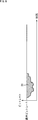
- FIG. 8 is a diagram illustrating an example of an actual bit rate of the audio stream when the encoding method is the lossless DSD method.
- the encoding method is the lossless DSD method
- the actual bit rate of the audio stream varies below the maximum bit rate indicated by Bandwidth.
- the actual bit rate of the audio stream is unpredictable. Therefore, when the moving image content is distributed live, the moving image playback terminal 14 cannot recognize the actual bit rate of the audio stream until the audio stream is acquired.
- the video playback terminal 14 acquires the actual bit rate of the audio stream by acquiring the audio stream before selecting the bit rate of the video stream.
- the moving image reproduction terminal 14 can allocate a band other than the actual bit rate of the audio stream in the network band of the Internet 13 to the video stream. That is, the surplus bandwidth 81 that is the difference between the maximum bit rate of the audio stream and the actual bit rate can be assigned to the video stream.
- the surplus band 81 cannot be allocated to the video stream, and the use of the band is wasted.
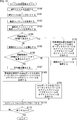
- FIG. 9 is a flowchart for explaining the playback process of the streaming playback unit 60 of FIG. This reproduction process is started when an MPD file is acquired and at least one of the encoding method information of each audio stream generated as a result of the analysis of the MPD file indicates that it is not a fixed method.
- the segment file acquisition unit 63 selects the smallest bandwidth of the video stream and the audio stream from the bandwidth of each encoded stream supplied from the MPD processing unit 62.
- step S32 the segment file acquisition unit 63 obtains information on the acquisition of the segment file having a predetermined time length from the reproduction start time among the segment files of the bandwidth video stream and the audio stream selected in step S31 on a segment basis.
- the data is transmitted to the server 12, and the segment file is acquired in units of segments.
- This predetermined time length is a time length of an encoded stream that is desirably held in the buffer 65 before the start of decoding for detecting the network bandwidth of the Internet 13.
- the predetermined time length is 25% of the time length of the encoded stream that can be held in the buffer 65 (for example, about 30 to 60 seconds) (hereinafter referred to as the maximum time length).
- the segment file acquisition unit 63 supplies the encoded stream stored in each acquired segment file to the buffer 65 to hold it.
- step S33 the decoding unit 66 starts decoding the encoded stream stored in the buffer 65. Note that the encoded stream read and decoded by the decoding unit 66 is deleted from the buffer 65.
- the decoding unit 66 supplies a video digital signal or audio digital signal of the moving image content obtained as a result of the decoding to the output control unit 67. Based on the video digital signal supplied from the decoding unit 66, the output control unit 67 displays an image on a display unit such as a display (not shown) included in the video playback terminal 14.
- the output control unit 67 performs D / A conversion on the audio digital signal supplied from the decoding unit 66 and, based on the audio analog signal obtained as a result, a speaker (not shown) included in the video playback terminal 14 or the like. The sound is output to the output unit.
- step S34 the segment file acquisition unit 63 detects the network bandwidth of the Internet 13.
- step S35 the segment file acquisition unit 63 selects the bandwidth of the video stream and the audio stream based on the network bandwidth of the Internet 13 and the bandwidth of each encoded stream. Specifically, the segment file acquisition unit 63 selects the bandwidth of the video stream and the audio stream so that the sum of the bandwidths of the selected video stream and audio stream is equal to or less than the network bandwidth of the Internet 13.
- step S36 the segment file acquisition unit 63 acquires a segment file having a predetermined time length from the next time of the segment file acquired in step S32 among the segment files of the Bandwidth audio stream selected in step S35. Information is transmitted to the Web server 12 in segment units, and segment files are acquired in segment units.
- the predetermined time length may be any time length as long as the time length of the encoded stream held in the buffer 65 is smaller than the time length that is insufficient with respect to the maximum time length.
- the segment file acquisition unit 63 supplies the audio stream stored in each acquired segment file to the buffer 65 to hold it.
- step S37 the segment file acquisition unit 63 detects the actual bit rate of the audio stream acquired in step S36 and supplies it to the selection unit 64.
- step S38 the selection unit 64 determines whether or not to reselect the bandwidth of the video stream based on the actual bit rate of the audio stream, the bandwidth of the video stream, and the network bandwidth of the Internet 13.
- the selection unit 64 determines whether the bandwidth of the video stream that is the largest or less than the value obtained by subtracting the actual bit rate of the audio stream from the network bandwidth of the Internet 13 is the bandwidth of the video stream selected in step S35. Determine if.
- the selection unit 64 determines to reselect the bandwidth of the video stream. On the other hand, if it is determined in step S35 that the bandwidth of the video stream is selected, the selection unit 64 determines not to reselect the bandwidth of the video stream.
- step S38 If it is determined in step S38 that the band width of the video stream is to be selected again, the process proceeds to step S39.
- step S39 the selection unit 64 reselects the largest video stream Bandwidth that is equal to or smaller than the value obtained by subtracting the actual bit rate of the audio stream from the network bandwidth of the Internet 13. Then, the selection unit 64 supplies the reselected bandwidth to the segment file acquisition unit 63, and the process proceeds to step S40.
- step S38 determines whether the bandwidth of the video stream is selected again. If it is determined in step S38 that the bandwidth of the video stream is not selected again, the selection unit 64 supplies the bandwidth of the video stream selected in step S35 to the segment file acquisition unit 63, and the process is performed in step S40. Proceed to
- step S40 the segment file acquisition unit 63 acquires the segment file having a predetermined time length corresponding to the audio stream acquired in step S36 from the segment files of the video stream of Bandwidth supplied from the selection unit 64. Is sent to the Web server 12 in segment units, and the segment file is acquired in segment units. The segment file acquisition unit 63 supplies the video stream stored in each acquired segment file to the buffer 65 to hold it.
- step S41 the segment file acquisition unit 63 determines whether or not there is an empty space in the buffer 65. If it is determined in step S41 that the buffer 65 is not empty, the segment file acquisition unit 63 waits until the buffer 65 is empty.
- step S42 the streaming playback unit 60 determines whether or not to end the playback. If it is determined in step S42 that the reproduction is not to be terminated, the process returns to step S34, and the processes in steps S34 to S42 are repeated until the reproduction is terminated.
- step S43 the decoding unit 66 ends the decoding of all the encoded streams stored in the buffer 65, and then ends the decoding. Then, the process ends.
- the video playback terminal 14 acquires an audio stream encoded by the lossless DSD method before the video stream to acquire the actual bit rate of the audio stream, and acquires based on the actual bit rate. Select the Bandwidth of the video stream to be used.
- the file generation device 11 calculates the average value of the actual bit rate of the generated audio stream and describes it in the MPD file.
- the average value changes as the audio stream is generated, so the moving image playback terminal 14 needs to periodically acquire and update the MPD file.
- FIG. 10 is a diagram illustrating a first description example of the MPD file according to the second embodiment.
- the representation element further includes AveBandwidth and DurationForAveBandwidth.
- AveBandwidth is information indicating an average value of a predetermined period of the actual bit rate of the audio stream corresponding to the representation element.
- DurationForAveBandwidth is information indicating a predetermined period corresponding to AveBandwidth.
- the MPD file generation unit 34 in the second embodiment calculates an average value from the integrated value of the actual bit rates of the audio stream generated by the encoding unit 32 for each reference period. An average value of the actual bit rates of the audio stream in a predetermined period increased by the reference period is calculated.
- the MPD file generation unit 34 uses the calculated average value and a predetermined period corresponding to the average value as the bit rate information representing the actual bit rate of the audio stream for each reference period. Generate. Then, the MPD file generation unit 34 generates an MPD file including information indicating the average value of the bit rate information as AveBandwidth and including information indicating a predetermined period as DurationForAveBandwidth.
- the MPD file generation unit 34 calculates the average value of the actual bit rate of the audio stream for 600 seconds from the beginning. Therefore, DurationForAveBandwidth included in the three representation elements is PT600S indicating 600 seconds.
- AveBandwidth of the first representation element is 2000000.
- the average value of the actual bit rate for 600 seconds from the beginning of the lossless DSD audio stream whose maximum bit rate corresponding to the second representation element is 5.6 Mbps is 4 Mbps. Therefore, the AveBandwidth of the second representation element is 4000000.
- the average bit rate for 600 seconds from the beginning of the lossless DSD audio stream with a maximum bit rate of 11.2 Mbps corresponding to the third representation element is 8 Mbps. Therefore, the AveBandwidth of the third representation element is 8000000.
- FIG. 11 is a diagram illustrating a second description example of the MPD file according to the second embodiment.
- the configuration of the MPD file in FIG. 11 is different from the configuration of the MPD file in FIG. 5 in that two representation elements corresponding to an audio stream encoded by the lossless DSD method further have AveBandwidth and DurationForAveBandwidth.
- the AveBandwidth and DurationForAveBandwidth included in the two representation elements are the same as the AveBandwidth and DurationForAveBandwidth included in the first and second representation elements in FIG.
- the MPD file generation unit 34 may describe the time of the moving image content as DurationForAveBandwidth or the description of DurationForAveBandwidth when calculating the average value from the accumulated value accumulated up to the bit rate of the last audio stream of the moving image content. May be omitted.
- the MPD file in FIGS. 10 and 11 includes a minimum UpdatePeriod indicating a reference period as an update interval of the MPD file. Then, the moving image playback terminal 14 updates the MPD file at the update interval indicated by minimumUpdatePeriod. Therefore, the MPD file generation unit 34 can easily change the update interval of the MPD file only by changing the minimumUpdatePeriod described in the MPD file.
- AveBandwidth and DurationForAveBandwidth in FIGS. 10 and 11 may be described as SupplementalPropertyaldescriptor instead of being described as a parameter of the representation element.
- AveBandwidth instead of AveBandwidth in FIGS. 10 and 11, an integrated value of the actual bit rate of the audio stream in a predetermined period may be described.
- DASH audio: cbr: 2015 ”>
- AveBandwidth and DurationForAveBandwidth can be described. Therefore, the MPD files in FIGS. 10 and 11 are compatible with MPD files that are not assumed to be non-fixed as the audio stream encoding method.
- FIG. 12 is a flowchart for explaining file generation processing of the file generation apparatus 11 according to the second embodiment. This file generation process is performed when at least one of the encoding methods of the audio stream is the lossless DSD method.
- the MPD file generation unit 34 of the file generation device 11 generates an MPD file.
- the same value as the Bandwidth is described in the AveBandwidth of the MPD file, and PT0S indicating 0 second is indicated in the DurationForAveBandwidth. Described.
- a reference period ⁇ T is set in the minimumUpdatePeriod of the MPD file.
- the MPD file generation unit 34 supplies the generated MPD file to the upload unit 35.
- steps S61 to S65 is the same as the processing of steps S11 to S15 in FIG.
- step S66 the MPD file generation unit 34 integrates the actual bit rate of the audio stream with the accumulated value held, and holds the accumulated value obtained as a result.
- step S67 the MPD file generation unit 34 determines whether or not the actual bit rate of the audio stream at the playback time one second before the update time of the MPD file has been integrated by the processing in step S66.
- the MPD file generation unit 34 plays back 1 second before the update time. It is determined whether or not the actual bit rate of the audio stream at the time has been accumulated.
- the time is of course not limited to 1 second, and if it is other than 1 second, it is determined whether or not the actual bit rate of the audio stream at the playback time before the update time has been integrated by that time.
- the MPD file update time in the first step S67 is after the reference period ⁇ T from 0 seconds, and the MPD file update time in the next step S67 is twice the reference period ⁇ T from 0 seconds. It is. Thereafter, similarly, the update time of the MPD file increases by the reference period ⁇ T.
- step S67 If it is determined in step S67 that the actual bit rate of the audio stream at the playback time one second before the update time of the MPD file has been accumulated by the process in step S66, the process proceeds to step S68.
- step S68 the MPD file generation unit 34 calculates the average value by dividing the accumulated value held by the period of the audio stream corresponding to the accumulated bit rate.
- step S69 the MPD file generation unit 34 updates the AveBandwidth and DurationForAveBandwidth of the MPD file to information indicating the average value calculated in step S67 and information indicating a period corresponding to the average value, respectively. Proceed to S70.
- step S67 if it is determined in step S67 that the actual bit rate of the audio stream at the playback time one second before the update time of the MPD file has not been accumulated in step S66, the process proceeds to step S70.
- step S70 is the same as the processing in step S16 in FIG.
- FIG. 13 is a flowchart for explaining the MPD file update processing of the streaming playback unit 60 in the second embodiment. This MPD file update process is performed when minimumUpdatePeriod is described in the MPD file.
- the MPD acquisition unit 61 of the streaming playback unit 60 acquires the MPD file and supplies it to the MPD processing unit 62.
- the MPD processing unit 62 analyzes the MPD file supplied from the MPD acquisition unit 61, thereby acquiring the update interval indicated by the minimumUpdatePeriod from the MPD file.
- the MPD processing unit 62 analyzes the MPD file to obtain the bandwidth of the encoded stream, acquisition information, encoding method information, and the like. Furthermore, when the MPD processing unit 62 analyzes the MPD file to indicate that the encoding method information is not a fixed method, the MPD processing unit 62 acquires the AveBandwidth of the audio stream and sets it as the selection bit rate. When the encoding method information indicates a fixed method, the MPD processing unit 62 sets the bandwidth of the audio stream as the selection bit rate.
- the MPD processing unit 62 supplies the band width and acquisition information of each video stream, the bit rate for selection of each audio stream, the acquisition information, and the encoding method information to the segment file acquisition unit 63. In addition, the MPD processing unit 62 supplies the selection unit 64 with the bit rate for selection of each audio stream.
- step S93 the MPD acquisition unit 61 determines whether or not the update interval has elapsed since the acquisition of the MPD file by the process of the previous step S91. If it is determined in step S93 that the update interval has not elapsed, the MPD acquisition unit 61 waits until the update interval elapses.
- step S93 If it is determined in step S93 that the update interval has elapsed, the process proceeds to step S94.
- step S94 the streaming playback unit 60 determines whether or not to end the playback process. If it is determined in step S94 that the reproduction process is not terminated, the process returns to step S91, and the processes in steps S91 to S94 are repeated until the reproduction process is terminated.
- step S94 if it is determined in step S94 that the reproduction process is to be terminated, the process is terminated.
- FIG. 14 is a flowchart for explaining the playback process of the streaming playback unit 60 in the second embodiment. This reproduction process is performed in parallel with the MPD file update process of FIG.
- the segment file acquisition unit 63 selects the smallest video stream Bandwidth and audio stream selection bit rate supplied from the MPD processing unit 62.
- step S112 the segment file acquisition unit 63 acquires the segment file having a predetermined time length from the reproduction start time among the segment files of the video stream having the bandwidth and the audio stream having the selection bit rate selected in step S111. Is sent to the Web server 12 in segment units, and the segment file is acquired in segment units. This predetermined time length is the same as the time length in step S32 of FIG. The segment file acquisition unit 63 supplies the acquired segment file to the buffer 65 to hold it.
- steps S113 and S114 is the same as the processing in steps S33 and S34 in FIG.
- step S115 the segment file acquisition unit 63 selects the video stream bandwidth and the audio stream selection bit rate based on the network bandwidth of the Internet 13, the video stream bandwidth and the audio stream selection bit rate. .
- the segment file acquisition unit 63 sets the video stream Bandwidth and the audio stream so that the sum of the Bandwidth of the selected video stream and the bit rate for selecting the audio stream is equal to or less than the network bandwidth of the Internet 13. Select the bit rate for selection.
- step S116 the segment file acquisition unit 63 determines a predetermined time from the next time of the segment file acquired in step S112 out of the segment files of the bandwidth video stream and the selection bit rate audio stream selected in step S115.
- the segment file acquisition information of the time length is transmitted to the Web server 12 in segment units, and the segment file is acquired in segment units.
- the segment file acquisition unit 63 supplies the acquired segment file to the buffer 65 to hold it.
- AveBandwidth is an average value of the actual bit rate of the audio stream
- the actual bit rate may exceed AveBandwidth. Accordingly, the predetermined time length in step S116 is set to be shorter than the reference period ⁇ T. As a result, when the actual bit rate exceeds AveBandwidth, the network bandwidth of the Internet 13 is reduced, and an audio stream having a lower selection bit rate is acquired. As a result, overflow of the buffer 65 can be prevented.
- steps S117 to S119 is the same as the processing of steps S41 to S43 in FIG.
- the file generation device 11 generates an average value of actual bit rates of audio streams encoded by the lossless DSD method. Accordingly, the video playback terminal 14 selects the bandwidth of the video stream to be acquired based on the average value of the actual bit rate of the audio stream, thereby obtaining a surplus bandwidth that is a difference between the bandwidth of the audio stream and the actual bit rate. At least a portion of which can be allocated to the video stream. As a result, it is possible to acquire a video stream having an optimum bit rate as compared with the case where the bandwidth of the video stream to be acquired is selected based on the bandwidth of the audio stream.
- the video playback terminal 14 acquires the latest MPD file at the playback start time, thereby obtaining the latest You can get AveBandwidth.
- update notification information for notifying the update time of the MPD file is mainly stored in the media segment file of the audio stream instead of describing the minimumUpdatePeriod in the MPD file. This is different from the second embodiment. Therefore, hereinafter, only the segment file of the audio stream, the file generation process, the MPD file update process, and the playback process will be described.
- FIG. 15 is a diagram illustrating a configuration example of a media segment file including audio stream update notification information according to the third embodiment.
- the media segment file (Media Segment) in FIG. 15 is composed of a styp box, a sidx box, an emsg box (Event Message Box), and one or more Movie fragments.
- the styp box is a box that stores information indicating the format of the media segment file.
- msdh indicating that the format of the media segment file is the MPEG-DASH format is stored in the styp box.
- the sidx box is a box for storing index information of sub-segments composed of one or more Movie fragments.
- the emsg box is a box for storing update notification information using MPD validation validation.
- Movie fragment is composed of moof box and mdat box.
- the moof box is a box for storing audio stream metadata
- the mdat box is a box for storing an audio stream.
- a Movie fragment constituting a Media segment is divided into one or more sub-segments.
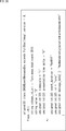
- FIG. 16 is a diagram illustrating a description example of the emsg box in FIG.
- string_value, presentation_time_delta, event_duration, id, message_data, etc. are described in the emsg box.
- “String value” is a value defining an event corresponding to this emsg box, and in the case of FIG. 16, it is 1 indicating updating of the MPD file.
- Presentation_time_delta is the time from the playback time of the media segment file in which the emsg box is arranged to the playback time at which the event is performed. Therefore, in the case of FIG. 16, presentation_time_delta is the time from the playback time of the media segment file in which this emsg box is arranged to the playback time when the MPD file is updated, and is update notification information. In the third embodiment, presentation_time_delta is 5. Accordingly, the MPD file is updated 5 seconds after the playback time of the media segment file in which this emsg box is arranged.
- Event_duration is the period of the event corresponding to this emsg box. In the case of FIG. 16, “event_duration” is “0xFFFF” indicating that the period is unknown. id is an ID unique to this emsg box. Further, message_data is data related to the event corresponding to this emsg box, and in the case of FIG. 16, is the XML (Extensible Markup Language) data of the update time of the MPD file.
- XML Extensible Markup Language
- the file generation device 11 includes the emsg box of FIG. 16 for storing presentation_time_delta in the media segment file of the audio stream as necessary. Thereby, the file generation device 11 can notify the moving image playback terminal 14 of how many seconds after the playback time of the media segment file the MPD file is updated.
- the file generation device 11 can easily change the update frequency of the MPD file only by changing the frequency with which the emsg box is arranged in the media segment file.
- FIG. 17 is a flowchart for explaining file generation processing of the file generation apparatus 11 according to the third embodiment. This file generation process is performed when at least one of the encoding methods of the audio stream is the lossless DSD method.
- the MPD file generation unit 34 of the file generation device 11 generates an MPD file.
- This MPD file is different from the MPD file in the second embodiment in that minimumUpdatePeriod is not described and “urn: mpeg: dash: profile: is-off-ext-live: 2014” is described. “Urn: mpeg: dash: profile: is-off-ext-live: 2014” is a profile indicating that the emsg box of FIG. 16 is arranged in the media segment file.
- the MPD file generation unit 34 supplies the generated MPD file to the upload unit 35.
- step S134 the segment file generation unit 33 of the file generation device 11 determines whether or not the reproduction time of the audio digital signal encoded in step S133 is 5 seconds before the update time of the MPD file.
- the segment file generation unit 33 determines whether it is 5 seconds before the update time of the MPD file in order to notify the moving image playback terminal 14 of the update of the MPD file 5 seconds before.
- the notification to the video playback terminal 14 may, of course, be performed only before a time other than 5 seconds, and when performed before a time other than 5 seconds, the MPD file is updated by that time only. It is determined whether it is before.
- the MPD file update time in the first step S134 is after the reference period ⁇ T from 0 seconds, and the MPD file update time in the next step S134 is twice the reference period ⁇ T from 0 seconds. It is. Thereafter, similarly, the update time of the MPD file increases by the reference period ⁇ T.
- step S134 If it is determined in step S134 that it is 5 seconds before the update time of the MPD file, the process proceeds to step S135.
- step S135 the segment file generation unit 33 generates a segment file of the audio stream supplied from the encoding unit 32 including the emsg box of FIG.
- the segment file generation unit 33 generates a segment file of the video stream supplied from the encoding unit 32. Then, the segment file generation unit 33 supplies the generated segment file to the upload unit 35, and the process proceeds to step S137.
- step S136 the segment file generation unit 33 generates a segment file of the audio stream supplied from the encoding unit 32 that does not include the emsg box of FIG.
- the segment file generation unit 33 generates a segment file of the video stream supplied from the encoding unit 32. Then, the segment file generation unit 33 supplies the generated segment file to the upload unit 35, and the process proceeds to step S137.
- steps S137 to S142 Since the processing of steps S137 to S142 is the same as the processing of steps S65 to S70 of FIG.
- the MPD file update processing of the streaming playback unit 60 in the third embodiment is performed when the media segment file acquired by the segment file acquisition unit 63 includes the emsg box of FIG. This is a process in which the MPD acquisition unit 61 acquires an MPD file in seconds.
- presentation_time_delta is 5, but of course it is not limited to this.
- the playback process of the streaming playback unit 60 in the third embodiment is the same as the playback process of FIG. 14, and is performed in parallel with the MPD file update process.
- the video playback terminal 14 since the video playback terminal 14 only needs to acquire the MPD file when acquiring the media segment file including the emsg box, HTTP overhead other than acquisition of the encoded stream is required. Can be suppressed.
- the fourth embodiment of the information processing system to which the present disclosure is applied mainly stores the update values of AveBandwidth and DurationForAveBandwidth as update information (difference information before and after update) of the MPD file, rather than updating the MPD file.
- the difference from the third embodiment is that the emsg box is arranged in the segment file of the audio stream.
- the initial values of AveBandwidth and DurationForAveBandwidth are included in the MPD file, and the updated values of AveBandwidth and DurationForAveBandwidth are included in the segment file of the audio stream. Therefore, hereinafter, only the emsg box for storing the updated values of AveBandwidth and DurationForAveBandwidth, file generation processing, MPD file update processing, and playback processing will be described.
- FIG. 18 is a diagram illustrating a description example of an emsg box that stores update values of AveBandwidth and DurationForAveBandwidth in the fourth embodiment.
- string value is 2 indicating transmission of update information of the MPD file.
- presentation_time_delta 0 is set as the time from the playback time of the media segment file in which this emsg box is arranged to the playback time at which the update information of the MPD file is transmitted.
- message_data is XML data of update values of AveBandwidth and DurationForAveBandwidth which are update information of the MPD file.
- FIG. 19 is a flowchart for describing file generation processing of the file generation apparatus 11 according to the fourth embodiment. This file generation process is performed when at least one of the encoding methods of the audio stream is the lossless DSD method.
- step S160 of FIG. 19 the MPD file generation unit 34 of the file generation device 11 generates an MPD file.
- This MPD file is the same as the MPD file in the third embodiment, except that the profile is replaced with a profile indicating that the emsg box in FIGS. 16 and 18 is arranged in the media segment file.
- the MPD file generation unit 34 supplies the generated MPD file to the upload unit 35.
- steps S161 to S164 is the same as the processing of steps S131 to S134 in FIG.
- step S164 If it is determined in step S164 that it is not 5 seconds before the update time of the MPD file, the process proceeds to step S165.
- the processing in steps S165 to S167 is the same as the processing in steps S138 to S140 in FIG.
- the segment file generation unit 33 includes the average value calculated in step S167 as the updated value of AveBandwidth, and includes the emsg box of FIG. 18 including the period corresponding to the average value as the updated value of DurationForAveBandwidth.
- the segment file of the audio stream supplied from the conversion unit 32 is generated.
- the segment file generation unit 33 generates a segment file of the video stream supplied from the encoding unit 32. Then, the segment file generation unit 33 supplies the generated segment file to the upload unit 35, and the process proceeds to step S172.
- step S166 determines whether the actual bit rate of the audio stream at the playback time one second before the update time of the MPD file has not yet been integrated. If it is determined in step S166 that the actual bit rate of the audio stream at the playback time one second before the update time of the MPD file has not yet been integrated, the process proceeds to step S169.
- step S169 the segment file generation unit 33 generates a segment file of the audio stream supplied from the encoding unit 32 that does not include the emsg box of FIG. 16 and the emsg box of FIG. In addition, the segment file generation unit 33 generates a segment file of the video stream supplied from the encoding unit 32. Then, the segment file generation unit 33 supplies the generated segment file to the upload unit 35, and the process proceeds to step S172.
- the segment file generation unit 33 is supplied from the encoding unit 32 including the emsg box for storing the update notification information in FIG. Generate a segment file of the audio stream to be played. In addition, the segment file generation unit 33 generates a segment file of the video stream supplied from the encoding unit 32. Then, the segment file generation unit 33 supplies the generated segment file to the upload unit 35.
- step S171 the MPD file generation unit 34 integrates the actual bit rate of the audio stream with the accumulated value held, holds the accumulated value obtained as a result, and advances the process to step S172.
- step S172 the upload unit 35 uploads the segment file supplied from the segment file generation unit 33 to the Web server 12.
- step S173 is the same as the processing in step S142 in FIG.
- the MPD file update process of the streaming playback unit 60 in the fourth embodiment is performed when the media segment file acquired by the segment file acquisition unit 63 includes the emsg box of FIG. This is a process of acquiring the updated values of AveBandwidth and DurationForAveBandwidth from the emsg box of FIG. 18 of the media segment file after 2 seconds, and updating the MPD file.
- the playback process of the streaming playback unit 60 in the fourth embodiment is the same as the playback process of FIG. 14, and is performed in parallel with the MPD file update process.
- the MPD processing unit 62 only needs to analyze the description about the AveBandwidth and DurationForAveBandwidth for the updated MPD file, so the analysis load is reduced.
- ⁇ Fifth embodiment> (Emsg box description example)
- the initial values of AveBandwidth and DurationForAveBandwidth are not described in the MPD file, and the emsg box for storing update notification information is mainly included in the segment file of the audio stream. It is different from the fourth embodiment in that it is not arranged. Therefore, hereinafter, only the emsg box for storing AveBandwidth and DurationForAveBandwidth, file generation processing, update processing of AveBandwidth and DurationForAveBandwidth, and playback processing will be described.
- FIG. 20 is a diagram illustrating a description example of an emsg box that stores AveBandwidth and DurationForAveBandwidth in the fifth embodiment.
- string value is 3 indicating transmission of AveBandwidth and DurationForAveBandwidth.
- presentation_time_delta 0 is set as the time from the playback time of the media segment file in which this emsg box is placed to the playback time at which AveBandwidth and DurationForAveBandwidth are transmitted.
- the moving image playback terminal 14 can recognize that AveBandwidth and DurationForAveBandwidth are arranged in the media segment file in which the emsg box is arranged.
- the event_duration is “0xFFFF” as in the case of FIG.
- Message_data is XML data of AveBandwidth and DurationForAveBandwidth.
- the file generation device 11 can easily change the update frequency of AveBandwidth and DurationForAveBandwidth only by changing the arrangement frequency of the emsg box of FIG. 20 in the media segment file of the audio stream.
- the file generation processing of the file generation device 11 in the fifth embodiment is mainly that the processing in steps S164, S170, and S171 is not performed, and the emsg box in FIG. Except for the point that replaces the emsg box in FIG. 20, this is the same as the file generation process in FIG.
- AveBandwidth and DurationForAveBandwidth are not described in the MPD file in the fifth embodiment.
- the profile described in the MPD file is a profile indicating that the emsg of FIG. 20 is arranged in the segment file, and is, for example, “urn: mpeg: dash: profile: isoff-dynamic-bandwidth: 2015”. .
- AveBandwidth and DurationForAveBandwidth update processing of the streaming playback unit 60 in the fifth embodiment is performed instead of the MPD file update processing in the fourth embodiment.
- the update process of AveBandwidth and DurationForAveBandwidth is a process of acquiring AveBandwidth and DurationForAveBandwidth from the emsg box and updating AveBandwidth and DurationForAveBandwidth when the media segment file acquired by the segment file acquisition unit 63 includes the emsg box of FIG. It is.
- the AveBandwidth of the selection bit rate in step S111 is not supplied from the MPD processing unit 62, but is updated by the segment file acquisition unit 63 itself. Except for this point, it is the same as the reproduction process of FIG. This reproduction process is performed in parallel with the update process of AveBandwidth and DurationForAveBandwidth.
- AveBandwidth and DurationForAveBandwidth are arranged in the emsg box, it is not necessary to analyze the MPD file every time AveBandwidth and DurationForAveBandwidth are updated.
- AveBandwidth and DurationForAveBandwidth are not stored in the emsg box, but may be periodically transmitted from the Web server 12 in conformity with other standards such as HTTP 2.0 and WebSocket. In this case, the same effect as that of the fifth embodiment can be obtained.
- an emsg box for storing update notification information may be arranged in the segment file.
- the sixth embodiment of the information processing system to which the present disclosure is applied mainly differs from the fifth embodiment in that XML data of AveBandwidth and DurationForAveBandwidth is arranged in a segment file different from the segment file of the audio stream. Different. Therefore, hereinafter, only a segment file (hereinafter referred to as a band segment file) that stores AveBandwidth and DurationForAveBandwidth, file generation processing, update processing of AveBandwidth and DurationForAveBandwidth, and playback processing will be described.
- a segment file hereinafter referred to as a band segment file
- FIG. 21 is a diagram showing a description example of the MPD file in the sixth embodiment.
- an update interval and a file URL that is the base of the name of the band segment file are set.
- the update interval is the reference period ⁇ T
- the file URL is “$ Bandwidth $ bandwidth.info”. Therefore, the base of the name of the band segment file is obtained by adding “bandwidth” to the Bandwidth of the representation element.
- the maximum bit rates of the three types of audio streams corresponding to the band segment file are 2.8 Mbps, 5.6 Mbps, and 11.2 Mbps. Accordingly, the three representation elements each have 280,000, 5600000, and 11200000 as the Bandwidth. Therefore, in the example of FIG. 21, the bases of the names of the band segment files are 280,000bandwidth.info, 5600000bandwidth.info, and 11200000 bandwidth.info.
- the segment info element included in the representation element has information on each band segment file of the band segment file group corresponding to the representation.
- the update interval is described in the MPD file. Therefore, the update frequency of AveBandwidth and DurationForAveBandwidth can be easily changed by simply changing the update interval described in the MPD file and the update interval of the band segment file.
- the MPD file generated in step S60 is the MPD file in FIG. 21, and the MPD file is converted in step S69. Except for the fact that a band segment file is generated by the segment file generation unit 33 without being updated and is uploaded to the Web server 12 via the upload unit 35, this is the same as the file generation processing of FIG.
- the update processing of AveBandwidth and DurationForAveBandwidth in the streaming playback unit 60 in the sixth embodiment is that the segment file acquisition unit 63 acquires the band segment file and updates AveBandwidth and DurationForAveBandwidth between step S93 and step S94. And when it determines with not complete
- the segment file acquisition unit 63 updates the AveBandwidth of the selection bit rate in step S111 instead of being supplied from the MPD processing unit 62. Except for this point, it is the same as the reproduction process of FIG. This reproduction process is performed in parallel with the update process of AveBandwidth and DurationForAveBandwidth.
- AveBandwidth and DurationForAveBandwidth are arranged in the band segment file, it is not necessary to analyze the MPD file every time AveBandwidth and DurationForAveBandwidth are updated.
- the segment length of the audio stream is variable so that the configuration of the MPD file and the actual bit rate of the segment file of the audio stream are within a predetermined range. This is different from the second embodiment. Therefore, only the configuration of the MPD file and the segment file will be described below.
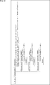
- FIG. 22 is a diagram illustrating a first description example of the MPD file according to the seventh embodiment.
- the adaptation set element of the segment file of the audio stream has ConsecutiveSegmentInformation indicating the segment length of each segment file.
- the segment length changes with a positive multiple of the fixed segment length as the reference time.
- the segment file is configured by concatenating one or more segment files having a fixed segment length.
- MaxConsecutiveNumber is described as the value (Value) of ConsecutiveSegmentInformation, and then FirstSegmentNumber and ConsecutiveNumbers are repeatedly described in order.
- MaxConsecutiveNumber is information indicating the maximum number of connected segment files with a fixed segment length.
- the fixed segment length is set based on the time scale and duration of the Segment Template included in the adaptation set element of the segment file of the audio stream. In the example of FIG. 22, since the timescale is 44100 and the duration is 88200, the fixed segment length is 2 seconds.
- FirstSegmentNumber is the number from the beginning of the first segment of consecutive segment groups with the same length, that is, the number included in the name of the first segment file of consecutive segment files with the same segment length. is there. ConsecutiveNumbers is information indicating how many times the segment length of the segment group corresponding to the immediately preceding FirstSegmentNumber is a fixed segment length.
- ConsecutiveSegmentInformation is 2,1,1,11,2,31,1. Therefore, the maximum number of connections with a fixed segment length is two. Also, the first media segment file corresponding to the representation element whose Bandwidth is 280,000, the maximum bit rate is 2.8 Mbps, and the file name is “2800000-1.mp4”, the file name is “2800000 -1.mp4 "is a concatenation of one media segment file with a fixed segment length. Therefore, the segment length of the media segment file whose file name is “2800000-1.mp4” is 2 seconds which is one time the fixed segment length.
- the second to tenth media segment files with file names “2800000-2.mp4” to “2800000-10.mp4” have file names “2800000-2.mp4” to “2800000”, respectively.
- -10.mp4 is one concatenated media segment file with a segment length of 2 seconds.
- the eleventh media segment file with the file name “2800000-11.mp4” has two fixed segment lengths with file names “2800000-11.mp4” and “2800000-12.mp4”.
- Media segment files are concatenated. Therefore, the segment length of the media segment file whose file name is “2800000-11.mp4” is 4 seconds, which is twice the fixed segment length. Further, the file name “2800000-12.mp4” of the media segment file linked to the media segment file whose file name is “2800000-11.mp4” is a missing number.
- the 12th to 19th media segment files with file names “2800000-13.mp4”, “2800000-15.mp4”,..., “2800000-29.mp4” are also fixed segment lengths.
- the two media segment files are connected, and the segment length is 4 seconds.
- the 20th media segment file with the file name “2800000-31.mp4” is the concatenation of one fixed segment length media segment file with the file name “2800000-31.mp4”. is there. Therefore, the segment length of the media segment file whose file name is “2800000-31.mp4” is 2 seconds which is one time the fixed segment length.
- the configuration of the media segment file whose maximum bit rate is 5.6 Mbps, 11.2 Mbps corresponding to the representation element whose Bandwidth is 5.600000, 11200000 is the same as the configuration of the media segment file whose maximum bit rate is 2.8 Mbps, Description is omitted.
- FIG. 23 is a diagram illustrating a second description example of the MPD file according to the seventh embodiment.
- the segment length changes at an arbitrary time. Therefore, timescale and duration are described as SegmentDuration.
- the timescale is a value representing 1 second, and 44100 is set in the example of FIG.
- FirstSegmentNumber and SegmentDuration are described repeatedly in order.
- FirstSegmentNumber is the same as FirstSegmentNumber in FIG.
- SegmentDuration is the segment length value of the segment group corresponding to the immediately preceding FirstSegmentNumber when the timescale is 1 second.
- segment lengths of the 12th to 14th media segment files having file names “2800000-12.mp4” to “2800000-14.mp4” are also 1 second.
- the configuration of media segment files with maximum bit rates of 5.6 Mbps and 11.2 Mbps corresponding to representation elements with bandwidths of 5.600000 and 11200000 is the same as the configuration of media segment files with 2.8 Mbps, so the description is omitted. .
- the segment file generation unit 33 sets the segment length based on the actual bit rate of the audio stream or the average value of the actual bit rates so that the bit rate is within a predetermined range. decide.
- the segment file since the segment file is distributed live, the segment length changes as the audio stream is generated. Therefore, the video playback terminal 14 needs to acquire and update the MPD file every time the segment length is changed.
- the segment length change timing is the same as the calculation timing of the average value of the actual bit rate of the audio stream, but may be different.
- information indicating the segment length update interval and update time is transmitted to the video playback terminal 14, and the video playback terminal 14 updates the MPD file based on the information.
- FIG. 24 is a diagram illustrating a configuration example of a media segment file of a lossless DSD audio stream according to the seventh embodiment.
- the configuration of the media segment file A in FIG. 24 is different from the configuration in FIG. 15 in that the Movie fragment does not have a fixed segment length but exists for a variable segment length, and the emsg box is not provided.
- the media segment file is configured by concatenating one or more media segment files having a fixed segment length as in the example of FIG. 22, the media segment file is as shown in FIG. It may be configured by simply concatenating one or more fixed segment length media segment files. In this case, there are as many styp boxes and sidx boxes as there are media segment files to be connected.
- the segment length of the audio stream is made variable so that the actual bit rate of the segment file of the audio stream is within a predetermined range. Therefore, even when the actual bit rate of the audio stream is small, the video playback terminal 14 can acquire the audio stream at a bit rate within a predetermined range by acquiring the segment file in segment units. .
- the information indicating the segment length of each segment file may be transmitted to the video playback terminal 14 in the same manner as AveBandwidth and DurationForAveBandwidth in the third to sixth embodiments.
- a file indicating the segment length of each segment file may be generated separately from the MPD file and transmitted to the moving image playback terminal 14.
- the segment length may be made variable as in the seventh embodiment.
- FIG. 25 is a block diagram illustrating a configuration example of a lossless compression encoding unit that performs A / D conversion on an audio analog signal and encodes the lossless DSD method in the acquisition unit 31 and the encoding unit 32 of FIG. 3.
- the lossless compression encoding unit 100 converts the audio analog signal into an audio digital signal by the DSD method, and performs lossless compression encoding on the converted audio digital signal and outputs the audio digital signal.
- the audio analog signal of the moving image content is input from the input unit 111 and supplied to the ADC 112.
- the ADC 112 includes an adder 121, an integrator 122, a comparator 123, a one-sample delay circuit 124, and a 1-bit DAC 125, and converts an audio analog signal into an audio digital signal by the DSD method.
- the audio analog signal supplied from the input unit 111 is supplied to the adder 121.
- the adder 121 adds the audio analog signal before one sample period supplied from the 1-bit DAC 125 and the audio analog signal from the input unit 111 and outputs the result to the integrator 122.
- the integrator 122 integrates the audio analog signal from the adder 121 and outputs it to the comparator 123.
- the comparator 123 performs 1-bit quantization by comparing the integration value of the audio analog signal supplied from the integrator 122 and the midpoint potential every sample period.
- the comparator 123 performs 1-bit quantization here, 2-bit quantization, 4-bit quantization, or the like may be performed. Further, as the frequency of the sampling period (sampling frequency), for example, a frequency that is 64 times or 128 times that of 48 kHz or 44.1 kHz is used.
- the comparator 123 outputs a 1-bit audio digital signal obtained by 1-bit quantization to the input buffer 113 and supplies it to the 1-sample delay circuit 124.
- the 1-sample delay circuit 124 delays the 1-bit audio digital signal from the comparator 123 by one sample period and outputs it to the 1-bit DAC 125.
- the 1-bit DAC 125 converts the audio digital signal from the 1-sample delay circuit 124 into an audio analog signal and outputs it to the adder 121.
- the input buffer 113 temporarily stores the 1-bit audio digital signal supplied from the ADC 112 and supplies it to the control unit 114, the encoding unit 115, and the data amount comparison unit 117 in units of one frame.
- one frame is a unit in which an audio digital signal is divided into a predetermined time (period) and regarded as one unit.
- the control unit 114 controls the overall operation of the lossless compression encoding unit 100.
- the control unit 114 has a function of creating a conversion table table1 necessary for the encoding unit 115 to perform lossless compression encoding and supplying the conversion table table1 to the encoding unit 115.
- control unit 114 creates a data generation count table pre_table in units of frames using one frame of audio digital signal supplied from the input buffer 113, and further converts the conversion table table1 from the data generation count table pre_table. create.
- the control unit 114 supplies the conversion table table1 created for each frame to the encoding unit 115 and the data transmission unit 118.
- the encoding unit 115 performs lossless compression encoding of the audio digital signal supplied from the input buffer 113 in units of 4 bits, using the conversion table table1 supplied from the control unit 114. Therefore, an audio digital signal is supplied from the input buffer 113 to the control unit 114 simultaneously with the timing supplied to the encoding unit 115, but the encoding unit 115 does not process until the conversion table table1 is supplied from the control unit 114. Wait.
- the encoding unit 115 performs lossless compression encoding of a 4-bit audio digital signal into a 2-bit audio digital signal or lossless compression code into a 6-bit audio digital signal. And output to the encoded data buffer 116.
- the encoded data buffer 116 temporarily buffers the audio digital signal generated as a result of lossless compression encoding by the encoding unit 115 and supplies the audio digital signal to the data amount comparison unit 117 and the data transmission unit 118.
- the data amount comparison unit 117 calculates the data amount of the audio digital signal that has not been losslessly compressed and supplied from the input buffer 113 and the audio digital signal that has been losslessly encoded and supplied from the encoded data buffer 116 as a frame. Compare by units.
- the encoding unit 115 performs lossless compression coding on a 4-bit audio digital signal into a 2-bit audio digital signal or a 6-bit audio digital signal as described above. There are cases where the data amount of the subsequent audio digital signal exceeds the data amount of the audio digital signal before the lossless compression encoding. Therefore, the data amount comparison unit 117 compares the data amount of the audio digital signal after the lossless compression encoding and the audio digital signal before the lossless compression encoding.
- the data amount comparison unit 117 selects the smaller data amount and supplies the data transmission unit 118 with selection control data indicating which one has been selected. Note that when the data amount comparison unit 117 supplies selection control data indicating that an audio digital signal before lossless compression encoding has been selected to the data transmission unit 118, the audio digital signal before lossless compression encoding is also data. The data is supplied to the transmission unit 118.
- the data transmission unit 118 is an audio digital signal supplied from the encoded data buffer 116 based on the selection control data supplied from the data amount comparison unit 117 or an audio digital signal supplied from the data amount comparison unit 117. Choose either When the data transmitting unit 118 selects the audio digital signal that has been losslessly encoded and supplied from the encoded data buffer 116, the data transmitting unit 118 uses the audio digital signal, selection control data, and the conversion table table1 supplied from the control unit 114. Create an audio stream. On the other hand, when the data transmission unit 118 selects an audio digital signal that has not been losslessly compressed and supplied from the data amount comparison unit 117, the data transmission unit 118 generates an audio stream from the audio digital signal and selection control data.
- the data transmission unit 118 outputs the generated audio stream via the output unit 119.
- the data transmitting unit 118 can also generate an audio stream by adding a synchronization signal and an error correction code (ECC) to an audio digital signal for each predetermined number of samples.
- ECC error correction code
- FIG. 26 is a diagram illustrating an example of a data generation count table generated by the control unit 114 of FIG.
- the control unit 114 divides the audio digital signal in units of frames supplied from the input buffer 113 in units of 4 bits.
- the divided i-th (i is an integer greater than 1) 4-bit audio digital signal from the head is referred to as D4 data D4 [i].
- the control unit 114 sequentially sets the nth (n> 3) D4 data D4 [n] from the top as D4 data to be processed for each frame.
- the control unit 114 performs processing for each pattern of the last three D4 data D4 [n-3], D4 [n-2], and D4 [n-1] in the past of the processing target D4 data D4 [n].
- the number of occurrences of D4 data D4 [n] is counted, and a data generation count table pre_table [4096] [16] shown in FIG. 26 is created.
- [4096] and [16] of the data generation count table pre_table [4096] [16] indicate that the data generation count table is a table (matrix) having 4096 rows and 16 columns, and [0] to [4095]. ] Correspond to the values that the past three D4 data D4 [n-3], D4 [n-2], D4 [n-1] can take, and each column of [0] to [15] This corresponds to the value that the D4 data D4 [n] to be processed can take.
- pre_table [1] [0] to [1] [15] are ⁇ 0,0,0,0,0,0,0,0,0,0,0,0,0,0,0,0,0,0,0,0,0,0 ⁇ .
- FIG. 27 is a diagram illustrating an example of the conversion table table1 generated by the control unit 114 of FIG.
- the control unit 114 creates a conversion table table1 [4096] [3] having 4096 rows and 3 columns based on the previously generated data generation count table pre_table.
- each row [0] to [4095] of the conversion table table1 [4096] [3] contains the past three D4 data D4 [n-3], D4 [n-2], and D4 [n-1].
- D4 [n] contains the past three D4 data D4 [n-3], D4 [n-2], and D4 [n-1].
- three values having a high occurrence frequency among the 16 values that can be taken by the D4 data D4 [n] to be processed are stored. .
- the first column [0] of the conversion table table1 [4096] [3] stores the value with the highest occurrence frequency (first), and the second column [1] has the second occurrence frequency value. Is stored, and the third column [2] stores the value of the third occurrence frequency.
- the conversion table table1 [4096] [3] based on the data generation count table pre_table of FIG. 26, as shown in FIG. 27, the conversion table table1 [4096] [3
- the table1 [117] [0] to [117] [2] on the 118th line of ⁇ ] becomes ⁇ 05,04,03 ⁇ . That is, in pre_table [117] [0] to [117] [15] on the 118th line of the data generation count table pre_table in FIG. 26, the value with the highest occurrence frequency (first) is “5” generated 31 times. ", The second value of occurrence frequency is" 4 "generated 20 times, and the third value of occurrence frequency is" 3 "generated 18 times.
- ⁇ 05 ⁇ is stored in the 118th row, first column table1 [117] [0] of the conversion table table1 [4096] [3], and the 118th row, second column table1 [117] [1] is stored.
- ⁇ 04 ⁇ is stored, and ⁇ 03 ⁇ is stored in the 118th row, third column table1 [117] [2].
- table1 [0] [0] to [0] [2] in the first row of the conversion table table1 [4096] [3] are pre_table [0] in the first row of the data generation count table pre_table in FIG. It is generated based on [0] to [0] [15]. That is, in pre_table [0] [0] to [0] [15] in the first row of the data generation count table pre_table in FIG. The generated value is “0”, and no other value is generated. Therefore, ⁇ 00 ⁇ is stored in the first row and first column table1 [0] [0] of the conversion table table1 [4096] [3], and the first row and second column table1 [0] [1] and the first row are stored.
- ⁇ Ff ⁇ representing that no data exists is stored in the first row and third column table1 [0] [2].
- the value indicating that data does not exist is not limited to ⁇ ff ⁇ and can be determined as appropriate. Since the value stored in each element of the conversion table table1 is one of “0” to “15”, it can be expressed in 4 bits, but it is expressed in 8 bits for ease of handling in terms of computer processing. Has been.
- the encoding unit 115 divides the audio digital signal in units of frames supplied from the input buffer 113 in units of 4 bits, similarly to the control unit 114.
- the control unit 114 performs lossless compression encoding on the nth D4 data D4 [n] from the beginning, the control unit 114 stores the three most recent past D4 data D4 [n-3], in the conversion table table1 [4096] [3]. Three values in the row corresponding to D4 [n-2] and D4 [n-1] are searched.
- the encoding unit 115 converts the D4 data D4 [n] subject to lossless compression encoding into the latest three previous D4 data D4 [n-3] and D4 [n-2] in the conversion table table1 [4096] [3].
- the encoding unit 115 converts the D4 data D4 [n] to be lossless compression encoded into the latest three previous D4 data D4 [n-3] and D4 [n] in the conversion table table1 [4096] [3].
- the encoding unit 115 corresponds to the last three past D4 data D4 [n-3], D4 [n-2], and D4 [n-1] in the conversion table table1 [4096] [3]. If the same value as the D4 data D4 [n] to be lossless compression encoded does not exist among the three values, a 6-bit value “00b +” with “00b” preceding the D4 data D4 [n] D4 [n] ”is generated as a lossless compression encoding result of the D4 data D4 [n].
- “01b”, “10b”, “11b”, “00b + D4 [n]”, b represents binary notation.
- the encoding unit 115 converts the 4-bit DSD data D4 [n] into the 2-bit value “01b”, “10b”, or “11b” using the conversion table table1. Alternatively, it is converted to a 6-bit value “00b + D4 [n]”, which is the lossless compression encoding result.
- the encoding unit 115 outputs the lossless compression encoding result to the encoded data buffer 116 as an audio digital signal subjected to lossless compression encoding.
- FIG. 28 is a block diagram illustrating a configuration example of a lossless compression decoding unit that decodes an audio stream in a lossless DSD scheme and performs D / A conversion in the decoding unit 66 and the output control unit 67 in FIG. 7.
- the lossless compression decoding unit 170 performs lossless compression decoding of the audio stream using lossless DSD, converts the resulting audio digital signal into an audio analog signal using DSD, and outputs the audio analog signal.
- the audio stream supplied from the buffer 65 in FIG. 7 is input from the input unit 171 and supplied to the data receiving unit 172.
- the data receiving unit 172 determines whether or not the audio digital signal is losslessly compressed based on selection control data indicating whether or not the audio digital signal included in the audio stream is losslessly encoded. When it is determined that the audio digital signal has been losslessly compressed and encoded, the data reception unit 172 converts the audio digital signal included in the audio stream as an audio digital signal that has been losslessly compressed and encoded, and stores the encoded data buffer. 173. In addition, the data reception unit 172 supplies the conversion table table1 included in the audio stream to the table storage unit 175.
- the data receiving unit 172 converts the audio digital signal included in the audio stream into the output buffer 176 as an audio digital signal that is not losslessly compressed and encoded. Supply.
- the table storage unit 175 stores the conversion table table1 supplied from the data receiving unit 172, and supplies it to the decoding unit 174.
- the encoded data buffer 173 temporarily stores the audio digital signal that has been losslessly encoded and supplied from the data receiving unit 172 in units of frames.
- the encoded data buffer 173 supplies the stored audio digital signal in units of frames to the subsequent decoding unit 174 in units of 2 bits that are continuous at a predetermined timing.
- the decoding unit 174 includes a 2-bit register 191, a 12-bit register 192, a conversion table processing unit 193, a 4-bit register 194, and a selector 195.
- the decoding unit 174 performs lossless compression decoding of the lossless compression encoded audio digital signal, and generates an audio digital signal before lossless compression encoding.
- the register 191 stores the 2-bit audio digital signal supplied from the encoded data buffer 173.
- the register 191 supplies the stored 2-bit audio digital signal to the conversion table processing unit 193 and the selector 195 at a predetermined timing.
- the 12-bit register 192 stores a 12-bit FIFO (First-In First-Out) 4-bit audio digital signal, which is a lossless compression decoding result, supplied from the selector 195. As a result, the register 192 stores D4 data which are the last three lossless compression decoding results of the lossless compression decoding result of the audio digital signal including the 2-bit audio digital signal stored in the register 191. .
- FIFO First-In First-Out
- the conversion table processing unit 193 ignores the audio digital signal because it is not registered in the conversion table table1 [4096] [3]. . Also, the conversion table processing unit 193 ignores a total of 4 bits of audio digital signals for 2 times supplied immediately after the 2 bits of audio digital signal supplied now.
- the conversion table processing unit 193 has three D4 data (12 bits) stored in the register 192. D4 data).
- the three read D4 data of the conversion table table1 from the table storage unit 175 are registered as D4 [n-3], D4 [n-2], and D4 [n-1].
- D4 data stored in the column indicated by the supplied 2-bit audio digital signal in the row is read out.
- the conversion table processing unit 193 supplies the read D4 data to the register 194.
- the register 194 stores 4-bit D4 data supplied from the conversion table processing unit 193.
- the register 194 supplies the stored 4-bit D4 data to the input terminal 196b of the selector 195 at a predetermined timing.
- the selector 195 selects the input terminal 196a when the 2-bit audio digital signal supplied from the register 191 is “00b”. Then, the selector 195 outputs the 4-bit audio digital signal input after “00b” to the input terminal 196a from the output terminal 197 to the register 192 and the output buffer 176 as a lossless compression decoding result.
- the selector 195 selects the input terminal 196b. Then, the selector 195 outputs the 4-bit audio digital signal input to the input terminal 196b as a lossless compression decoding result from the output terminal 197 to the register 192 and the output buffer 176.
- the output buffer 176 stores the audio digital signal not supplied with the lossless compression encoding supplied from the data receiving unit 172 or the audio digital signal that is the lossless compression decoding result supplied from the decoding unit 174, and stores it in the analog filter 177. Supply.
- the analog filter 177 performs predetermined filter processing such as a low-pass filter and a band-pass filter on the audio digital signal supplied from the output buffer 176, and outputs the result through the output unit 178.
- the conversion table table1 may be compressed by the lossless compression encoding unit 100 and supplied to the lossless compression decoding unit 170.
- the conversion table table1 may be set in advance and stored in the lossless compression encoding unit 100 and the lossless compression decoding unit 170.
- the number of conversion tables table1 may be plural.
- the jth (j is an integer greater than or equal to 0) conversion table table1 includes 3 (j ⁇ 1), 3 (j ⁇ 1) +1, 3 (j ⁇ 1) +2 D4 data is stored in each row. Further, the number of past D4 data corresponding to each row is not limited to three.
- the lossless compression encoding method is not limited to the above-described method, and may be, for example, the method described in JP-A-9-74358.
- ⁇ Eighth embodiment> (Description of computer to which the present disclosure is applied)
- the series of processes described above can be executed by hardware or can be executed by software.
- a program constituting the software is installed in the computer.
- the computer includes, for example, a general-purpose personal computer capable of executing various functions by installing various programs by installing a computer incorporated in dedicated hardware.
- FIG. 29 is a block diagram showing an example of the hardware configuration of a computer that executes the above-described series of processing by a program.
- a CPU Central Processing Unit
- ROM Read Only Memory
- RAM Random Access Memory
- An input / output interface 205 is further connected to the bus 204.
- An input unit 206, an output unit 207, a storage unit 208, a communication unit 209, and a drive 210 are connected to the input / output interface 205.
- the input unit 206 includes a keyboard, a mouse, a microphone, and the like.
- the output unit 207 includes a display, a speaker, and the like.
- the storage unit 208 includes a hard disk, a nonvolatile memory, and the like.
- the communication unit 209 includes a network interface and the like.
- the drive 210 drives a removable medium 211 such as a magnetic disk, an optical disk, a magneto-optical disk, or a semiconductor memory.
- the CPU 201 loads the program stored in the storage unit 208 to the RAM 203 via the input / output interface 205 and the bus 204 and executes the program. A series of processing is performed.
- the program executed by the computer 200 can be provided by being recorded in, for example, a removable medium 211 such as a package medium.
- the program can be provided via a wired or wireless transmission medium such as a local area network, the Internet, or digital satellite broadcasting.
- the program can be installed in the storage unit 208 via the input / output interface 205 by attaching the removable medium 211 to the drive 210.
- the program can be received by the communication unit 209 via a wired or wireless transmission medium and installed in the storage unit 208.
- the program can be installed in the ROM 202 or the storage unit 208 in advance.
- the program executed by the computer 200 may be a program that is processed in time series in the order described in this specification, or a necessary timing such as in parallel or when a call is made. It may be a program in which processing is performed.
- the system means a set of a plurality of components (devices, modules (parts), etc.), and it does not matter whether all the components are in the same housing. Accordingly, a plurality of devices housed in separate housings and connected via a network and a single device housing a plurality of modules in one housing are all systems. .
- the lossless DSD scheme in the first to eighth embodiments may be other than the lossless DSD scheme as long as it is a lossless compression scheme in which the amount of bits generated by lossless compression encoding cannot be predicted.
- the lossless DSD method in the first to eighth embodiments may be a FLAC (Free Lossless Audio Codec) method or an ALAC (Apple lossless Audio Codec) method.
- FLAC Free Lossless Audio Codec
- ALAC Apple lossless Audio Codec
- the information processing system 10 in the first to eighth embodiments does not lively distribute the segment file, but all the segment files of the moving image content are already stored in the Web server 12, and the segment file is turned on. You may make it deliver on demand.
- AveBandwidth described in the MPD file is an average value of the whole period of the moving image content. Therefore, in the second embodiment and the seventh embodiment, the video playback terminal 14 does not update the MPD file. In the third embodiment, the video playback terminal 14 updates the MPD file, but the MPD file does not change before and after the update.
- a segment file with a fixed segment length is generated when the segment file is generated, and the Web server 12 concatenates the segment files with the fixed segment length during on-demand distribution. Then, a segment file having a variable segment length may be generated and transmitted to the moving image playback terminal 14.
- the information processing system 10 in the first to eighth embodiments stores the segment file of the moving image content halfway in the Web server 12 and then performs near live distribution starting distribution from the first segment file of the moving image content. You may do it.
- the segment file that is already stored in the Web server 12 at the start of playback is processed in the same manner as on-demand distribution, and the segment file that is not yet stored in the Web server 12 at the start of playback is live-distributed.
- the same processing as in the case of is performed.
- AveBandwidth and DurationForAveBandwidth are arranged in the segment file. Therefore, even if there is a time from when the segment file of the video content is generated until it is played back, such as on-demand delivery or near live delivery, the video playback terminal 14 will have the latest AveBandwidth and DurationForAveBandwidth at the start of playback. Can't get. Therefore, the latest AveBandwidth and DurationForAveBandwidth may be stored again when a segment file storing AveBandwidth and DurationForAveBandwidth (updated values thereof) is transmitted. In this case, the video playback terminal 14 can recognize the latest AveBandwidth and DurationForAveBandwidth at the start of playback.
- AveBandwidth and DurationForAveBandwidth are described in the MPD file or segment file, but AveBandwidth and DurationForAveBandwidth for each arbitrary time may be listed.
- the video playback terminal 14 can perform fine band control.
- an arbitrary time is a fixed time, only one DurationForAveBandwidth may be described.
- this indication can also take the following structures.
- An acquisition unit that acquires an audio stream encoded by a lossless compression method before a video stream corresponding to the audio stream and detects a bit rate of the audio stream;
- a playback device comprising: a selection unit that selects the video stream to be acquired from the plurality of video streams having different bit rates based on the bit rate detected by the acquisition unit.
- the acquisition unit is configured to select the audio stream to be acquired from a plurality of the audio streams having different maximum bit rates based on bands used for acquiring the audio stream and the video stream. ).
- the acquisition unit is configured to select the audio stream to be acquired based on the maximum bit rate and the band of the audio stream included in a management file that manages the audio stream and the video stream.
- the acquisition unit is such that the encoding method of the audio stream is not encoded so that underflow or overflow does not occur in a fixed size buffer.
- the playback device according to any one of (1) to (3), configured to detect a bit rate of the audio stream.
- the lossless compression method is configured to be a lossless DSD (Direct Stream Digital) method, a FLAC (Free Lossless Audio Codec) method, or an ALAC (Apple lossless Audio Codec) method, and is any one of the above (1) to (4)
- Playback device An acquisition step of acquiring an audio stream encoded by a lossless compression method before a video stream corresponding to the audio stream and detecting a bit rate of the audio stream; And a selection step of selecting the video stream to be acquired from the plurality of video streams having different bit rates based on the bit rate detected by the processing of the acquisition step.
- a management file that manages an audio stream encoded using a lossless compression method and a video stream corresponding to the audio stream.
- the audio stream encoding method is a fixed-size buffer, and underflow or overflow occurs.
- a file generation device comprising: a file generation unit that generates a management file including information indicating that the system is not encoded in such a manner.
- the file generation device configured to include a maximum bit rate of the audio stream and a bit rate of the video stream.
- the lossless compression method is configured to be a lossless DSD (Direct Stream Digital) method, a FLAC (Free Lossless Audio Codec) method, or an ALAC (Apple lossless Audio Codec) method, according to the above (7) or (8) File generator.
- the file generation device is a management file for managing an audio stream encoded by a lossless compression method and a video stream corresponding to the audio stream, and the encoding method of the audio stream is an underflow with a fixed size buffer.
- a file generation method including a file generation step of generating a management file including information indicating that the data is not encoded so as not to cause an overflow.
- 11 file generation device 13 internet, 14 video playback terminal, 33 segment file generation unit, 34 MPD file generation unit, 63 segment file acquisition unit, 64 selection unit
Abstract
La présente invention concerne un dispositif de lecture et un procédé de lecture, ainsi qu'un dispositif de génération de fichier et un procédé de génération de fichier qui, lors de l'acquisition d'un flux audio et d'un flux vidéo codés avec un procédé de compression sans perte, permettent d'acquérir un flux vidéo d'un débit binaire optimal. Une unité d'acquisition de fichier de segment acquiert un flux audio codé avec un procédé DSD sans perte avant l'acquisition d'un flux vidéo correspondant au flux audio, et détecte le débit binaire du flux audio. Sur la base du débit binaire détecté par l'unité d'acquisition de fichier de segment, une unité de sélection sélectionne un flux vidéo à acquérir parmi de multiples flux vidéo de différents débits binaires. La présente invention peut s'appliquer, par exemple, à des terminaux de lecture de vidéo.
Priority Applications (3)
| Application Number | Priority Date | Filing Date | Title |
|---|---|---|---|
| JP2018508956A JPWO2017169720A1 (ja) | 2016-03-28 | 2017-03-14 | 再生装置および再生方法、並びにファイル生成装置およびファイル生成方法 |
| CN201780019067.1A CN108886638A (zh) | 2016-03-28 | 2017-03-14 | 再现装置和再现方法、以及文件生成装置和文件生成方法 |
| US16/086,427 US20190103122A1 (en) | 2016-03-28 | 2017-03-14 | Reproduction device and reproduction method, and file generation device and file generation method |
Applications Claiming Priority (2)
| Application Number | Priority Date | Filing Date | Title |
|---|---|---|---|
| JP2016063222 | 2016-03-28 | ||
| JP2016-063222 | 2016-03-28 |
Publications (1)
| Publication Number | Publication Date |
|---|---|
| WO2017169720A1 true WO2017169720A1 (fr) | 2017-10-05 |
Family
ID=59964323
Family Applications (1)
| Application Number | Title | Priority Date | Filing Date |
|---|---|---|---|
| PCT/JP2017/010104 WO2017169720A1 (fr) | 2016-03-28 | 2017-03-14 | Dispositif et procédé de lecture, dispositif et procédé de génération de fichier |
Country Status (4)
| Country | Link |
|---|---|
| US (1) | US20190103122A1 (fr) |
| JP (1) | JPWO2017169720A1 (fr) |
| CN (1) | CN108886638A (fr) |
| WO (1) | WO2017169720A1 (fr) |
Families Citing this family (3)
| Publication number | Priority date | Publication date | Assignee | Title |
|---|---|---|---|---|
| US11546402B2 (en) | 2019-01-04 | 2023-01-03 | Tencent America LLC | Flexible interoperability and capability signaling using initialization hierarchy |
| CN114500914A (zh) * | 2020-11-11 | 2022-05-13 | 中兴通讯股份有限公司 | 音视频转发方法、装置、终端与系统 |
| CN113709524B (zh) * | 2021-08-25 | 2023-12-19 | 三星电子(中国)研发中心 | 选择音视频流的比特率的方法及其装置 |
Citations (4)
| Publication number | Priority date | Publication date | Assignee | Title |
|---|---|---|---|---|
| JP2011237824A (ja) * | 1998-10-13 | 2011-11-24 | Victor Co Of Japan Ltd | 音声信号伝送装置、音声信号受信装置及び音声信号伝送システム |
| JP2013029679A (ja) * | 2011-07-28 | 2013-02-07 | Panasonic Corp | 圧縮オーディオ再生装置及び平均ビットレート算出方法 |
| JP2013219819A (ja) * | 2009-07-24 | 2013-10-24 | Netflix Inc | デジタルコンテンツの配布のための適応型ストリーミング |
| WO2015038578A2 (fr) * | 2013-09-12 | 2015-03-19 | Dolby Laboratories Licensing Corporation | Aspects de système d'un codec audio |
Family Cites Families (5)
| Publication number | Priority date | Publication date | Assignee | Title |
|---|---|---|---|---|
| JP4935385B2 (ja) * | 2007-02-01 | 2012-05-23 | ソニー株式会社 | コンテンツ再生方法およびコンテンツ再生システム |
| US20080189359A1 (en) * | 2007-02-01 | 2008-08-07 | Sony Corporation | Content providing method, content playback method, portable wireless terminal, and content playback apparatus |
| US8477950B2 (en) * | 2009-08-24 | 2013-07-02 | Novara Technology, LLC | Home theater component for a virtualized home theater system |
| JP6587046B2 (ja) * | 2013-07-08 | 2019-10-09 | サン パテント トラスト | 画像符号化方法、画像復号方法、画像符号化装置及び画像復号装置 |
| JP2015195488A (ja) * | 2014-03-31 | 2015-11-05 | ソニー株式会社 | 情報処理装置および情報処理方法 |
-
2017
- 2017-03-14 JP JP2018508956A patent/JPWO2017169720A1/ja not_active Abandoned
- 2017-03-14 WO PCT/JP2017/010104 patent/WO2017169720A1/fr active Application Filing
- 2017-03-14 CN CN201780019067.1A patent/CN108886638A/zh active Pending
- 2017-03-14 US US16/086,427 patent/US20190103122A1/en not_active Abandoned
Patent Citations (4)
| Publication number | Priority date | Publication date | Assignee | Title |
|---|---|---|---|---|
| JP2011237824A (ja) * | 1998-10-13 | 2011-11-24 | Victor Co Of Japan Ltd | 音声信号伝送装置、音声信号受信装置及び音声信号伝送システム |
| JP2013219819A (ja) * | 2009-07-24 | 2013-10-24 | Netflix Inc | デジタルコンテンツの配布のための適応型ストリーミング |
| JP2013029679A (ja) * | 2011-07-28 | 2013-02-07 | Panasonic Corp | 圧縮オーディオ再生装置及び平均ビットレート算出方法 |
| WO2015038578A2 (fr) * | 2013-09-12 | 2015-03-19 | Dolby Laboratories Licensing Corporation | Aspects de système d'un codec audio |
Also Published As
| Publication number | Publication date |
|---|---|
| CN108886638A (zh) | 2018-11-23 |
| US20190103122A1 (en) | 2019-04-04 |
| JPWO2017169720A1 (ja) | 2019-02-07 |
Similar Documents
| Publication | Publication Date | Title |
|---|---|---|
| US10735794B2 (en) | Information processing device, information processing method, and information processing system | |
| JP3957666B2 (ja) | マルチメディアストリーミング装置、マルチメディアストリーミングサーバ、マルチメディアストリーミングクライアント、マルチメディアストリーミング方法及びそのプログラムを記録した記録媒体 | |
| CN103858419B (zh) | 一种回放装置及回放内容的方法 | |
| WO2013008867A1 (fr) | Dispositif de transmission, procédé de commande d'un dispositif de transmission, programme de commande et support d'enregistrement | |
| WO2017138387A1 (fr) | Dispositif et procédé de traitement d'informations | |
| KR20170021778A (ko) | 정보 처리 장치 및 정보 처리 방법 | |
| JP6876928B2 (ja) | 情報処理装置および方法 | |
| US10375439B2 (en) | Information processing apparatus and information processing method | |
| WO2017169720A1 (fr) | Dispositif et procédé de lecture, dispositif et procédé de génération de fichier | |
| WO2017169721A1 (fr) | Dispositif de génération de fichier et procédé de génération de fichier | |
| JP7238948B2 (ja) | 情報処理装置および情報処理方法 | |
| WO2016002495A1 (fr) | Dispositif et procédé de traitement d'informations | |
| JP4526294B2 (ja) | ストリームデータ送信装置、受信装置、プログラムを記録した記録媒体、およびシステム | |
| JP2016059018A (ja) | 配信装置、再生装置および配信システム | |
| JP2004215074A (ja) | サーバ、送信レート制御方法、プログラムおよび記録媒体 | |
| JP2017098706A (ja) | 受信装置、セグメント取得方法、及びプログラム | |
| KR102343639B1 (ko) | 압축 부호화 장치 및 방법, 복호 장치 및 방법, 그리고 프로그램 | |
| US20110050895A1 (en) | Distributed Video Surveillance Storage Cost Reduction Using Statistical Multiplexing Principle | |
| US20200314163A1 (en) | Image processing device and method thereof | |
| JPWO2018198788A1 (ja) | 信号処理装置、信号処理方法、およびプログラム | |
| JPWO2018142947A1 (ja) | 情報処理装置および方法 | |
| US11792472B2 (en) | Schedule-based uninterrupted buffering and streaming | |
| KR102367134B1 (ko) | 가속기를 제어하는 방법 및 이를 이용한 가속기 | |
| KR20130029235A (ko) | 스트리밍 되어오는 동영상 파일을 실시간 변환하여 스트리밍 전송하는 방법 | |
| KR101684705B1 (ko) | 미디어 컨텐츠 재생 장치 및 방법 |
Legal Events
| Date | Code | Title | Description |
|---|---|---|---|
| WWE | Wipo information: entry into national phase |
Ref document number: 2018508956 Country of ref document: JP |
|
| NENP | Non-entry into the national phase |
Ref country code: DE |
|
| 121 | Ep: the epo has been informed by wipo that ep was designated in this application |
Ref document number: 17774264 Country of ref document: EP Kind code of ref document: A1 |
|
| 122 | Ep: pct application non-entry in european phase |
Ref document number: 17774264 Country of ref document: EP Kind code of ref document: A1 |