WO2017169077A1 - Motor - Google Patents
Motor Download PDFInfo
- Publication number
- WO2017169077A1 WO2017169077A1 PCT/JP2017/003548 JP2017003548W WO2017169077A1 WO 2017169077 A1 WO2017169077 A1 WO 2017169077A1 JP 2017003548 W JP2017003548 W JP 2017003548W WO 2017169077 A1 WO2017169077 A1 WO 2017169077A1
- Authority
- WO
- WIPO (PCT)
- Prior art keywords
- rotor
- axial direction
- resin
- motor
- hole
- Prior art date
Links
Images


Classifications
-
- H—ELECTRICITY
- H02—GENERATION; CONVERSION OR DISTRIBUTION OF ELECTRIC POWER
- H02K—DYNAMO-ELECTRIC MACHINES
- H02K1/00—Details of the magnetic circuit
- H02K1/06—Details of the magnetic circuit characterised by the shape, form or construction
- H02K1/22—Rotating parts of the magnetic circuit
- H02K1/28—Means for mounting or fastening rotating magnetic parts on to, or to, the rotor structures
- H02K1/30—Means for mounting or fastening rotating magnetic parts on to, or to, the rotor structures using intermediate parts, e.g. spiders
-
- F—MECHANICAL ENGINEERING; LIGHTING; HEATING; WEAPONS; BLASTING
- F04—POSITIVE - DISPLACEMENT MACHINES FOR LIQUIDS; PUMPS FOR LIQUIDS OR ELASTIC FLUIDS
- F04D—NON-POSITIVE-DISPLACEMENT PUMPS
- F04D19/00—Axial-flow pumps
- F04D19/002—Axial flow fans
-
- F—MECHANICAL ENGINEERING; LIGHTING; HEATING; WEAPONS; BLASTING
- F04—POSITIVE - DISPLACEMENT MACHINES FOR LIQUIDS; PUMPS FOR LIQUIDS OR ELASTIC FLUIDS
- F04D—NON-POSITIVE-DISPLACEMENT PUMPS
- F04D29/00—Details, component parts, or accessories
- F04D29/18—Rotors
- F04D29/181—Axial flow rotors
-
- H—ELECTRICITY
- H02—GENERATION; CONVERSION OR DISTRIBUTION OF ELECTRIC POWER
- H02K—DYNAMO-ELECTRIC MACHINES
- H02K1/00—Details of the magnetic circuit
- H02K1/06—Details of the magnetic circuit characterised by the shape, form or construction
- H02K1/22—Rotating parts of the magnetic circuit
- H02K1/27—Rotor cores with permanent magnets
- H02K1/2706—Inner rotors
- H02K1/272—Inner rotors the magnetisation axis of the magnets being perpendicular to the rotor axis
- H02K1/274—Inner rotors the magnetisation axis of the magnets being perpendicular to the rotor axis the rotor consisting of two or more circumferentially positioned magnets
- H02K1/2753—Inner rotors the magnetisation axis of the magnets being perpendicular to the rotor axis the rotor consisting of two or more circumferentially positioned magnets the rotor consisting of magnets or groups of magnets arranged with alternating polarity
- H02K1/276—Magnets embedded in the magnetic core, e.g. interior permanent magnets [IPM]
-
- H—ELECTRICITY
- H02—GENERATION; CONVERSION OR DISTRIBUTION OF ELECTRIC POWER
- H02K—DYNAMO-ELECTRIC MACHINES
- H02K1/00—Details of the magnetic circuit
- H02K1/06—Details of the magnetic circuit characterised by the shape, form or construction
- H02K1/22—Rotating parts of the magnetic circuit
- H02K1/32—Rotating parts of the magnetic circuit with channels or ducts for flow of cooling medium
-
- H—ELECTRICITY
- H02—GENERATION; CONVERSION OR DISTRIBUTION OF ELECTRIC POWER
- H02K—DYNAMO-ELECTRIC MACHINES
- H02K11/00—Structural association of dynamo-electric machines with electric components or with devices for shielding, monitoring or protection
- H02K11/30—Structural association with control circuits or drive circuits
-
- H—ELECTRICITY
- H02—GENERATION; CONVERSION OR DISTRIBUTION OF ELECTRIC POWER
- H02K—DYNAMO-ELECTRIC MACHINES
- H02K15/00—Methods or apparatus specially adapted for manufacturing, assembling, maintaining or repairing of dynamo-electric machines
- H02K15/12—Impregnating, heating or drying of windings, stators, rotors or machines
-
- H—ELECTRICITY
- H02—GENERATION; CONVERSION OR DISTRIBUTION OF ELECTRIC POWER
- H02K—DYNAMO-ELECTRIC MACHINES
- H02K21/00—Synchronous motors having permanent magnets; Synchronous generators having permanent magnets
- H02K21/12—Synchronous motors having permanent magnets; Synchronous generators having permanent magnets with stationary armatures and rotating magnets
- H02K21/14—Synchronous motors having permanent magnets; Synchronous generators having permanent magnets with stationary armatures and rotating magnets with magnets rotating within the armatures
- H02K21/16—Synchronous motors having permanent magnets; Synchronous generators having permanent magnets with stationary armatures and rotating magnets with magnets rotating within the armatures having annular armature cores with salient poles
-
- H—ELECTRICITY
- H02—GENERATION; CONVERSION OR DISTRIBUTION OF ELECTRIC POWER
- H02K—DYNAMO-ELECTRIC MACHINES
- H02K5/00—Casings; Enclosures; Supports
- H02K5/04—Casings or enclosures characterised by the shape, form or construction thereof
- H02K5/16—Means for supporting bearings, e.g. insulating supports or means for fitting bearings in the bearing-shields
- H02K5/173—Means for supporting bearings, e.g. insulating supports or means for fitting bearings in the bearing-shields using bearings with rolling contact, e.g. ball bearings
- H02K5/1732—Means for supporting bearings, e.g. insulating supports or means for fitting bearings in the bearing-shields using bearings with rolling contact, e.g. ball bearings radially supporting the rotary shaft at both ends of the rotor
-
- H—ELECTRICITY
- H02—GENERATION; CONVERSION OR DISTRIBUTION OF ELECTRIC POWER
- H02K—DYNAMO-ELECTRIC MACHINES
- H02K5/00—Casings; Enclosures; Supports
- H02K5/04—Casings or enclosures characterised by the shape, form or construction thereof
- H02K5/22—Auxiliary parts of casings not covered by groups H02K5/06-H02K5/20, e.g. shaped to form connection boxes or terminal boxes
- H02K5/225—Terminal boxes or connection arrangements
-
- H—ELECTRICITY
- H02—GENERATION; CONVERSION OR DISTRIBUTION OF ELECTRIC POWER
- H02K—DYNAMO-ELECTRIC MACHINES
- H02K7/00—Arrangements for handling mechanical energy structurally associated with dynamo-electric machines, e.g. structural association with mechanical driving motors or auxiliary dynamo-electric machines
- H02K7/08—Structural association with bearings
- H02K7/083—Structural association with bearings radially supporting the rotary shaft at both ends of the rotor
-
- H—ELECTRICITY
- H02—GENERATION; CONVERSION OR DISTRIBUTION OF ELECTRIC POWER
- H02K—DYNAMO-ELECTRIC MACHINES
- H02K7/00—Arrangements for handling mechanical energy structurally associated with dynamo-electric machines, e.g. structural association with mechanical driving motors or auxiliary dynamo-electric machines
- H02K7/14—Structural association with mechanical loads, e.g. with hand-held machine tools or fans
-
- H—ELECTRICITY
- H02—GENERATION; CONVERSION OR DISTRIBUTION OF ELECTRIC POWER
- H02K—DYNAMO-ELECTRIC MACHINES
- H02K9/00—Arrangements for cooling or ventilating
- H02K9/02—Arrangements for cooling or ventilating by ambient air flowing through the machine
-
- H—ELECTRICITY
- H02—GENERATION; CONVERSION OR DISTRIBUTION OF ELECTRIC POWER
- H02K—DYNAMO-ELECTRIC MACHINES
- H02K9/00—Arrangements for cooling or ventilating
- H02K9/02—Arrangements for cooling or ventilating by ambient air flowing through the machine
- H02K9/04—Arrangements for cooling or ventilating by ambient air flowing through the machine having means for generating a flow of cooling medium
- H02K9/06—Arrangements for cooling or ventilating by ambient air flowing through the machine having means for generating a flow of cooling medium with fans or impellers driven by the machine shaft
-
- H—ELECTRICITY
- H02—GENERATION; CONVERSION OR DISTRIBUTION OF ELECTRIC POWER
- H02K—DYNAMO-ELECTRIC MACHINES
- H02K2211/00—Specific aspects not provided for in the other groups of this subclass relating to measuring or protective devices or electric components
- H02K2211/03—Machines characterised by circuit boards, e.g. pcb
-
- H—ELECTRICITY
- H02—GENERATION; CONVERSION OR DISTRIBUTION OF ELECTRIC POWER
- H02K—DYNAMO-ELECTRIC MACHINES
- H02K2213/00—Specific aspects, not otherwise provided for and not covered by codes H02K2201/00 - H02K2211/00
- H02K2213/03—Machines characterised by numerical values, ranges, mathematical expressions or similar information
Definitions
- FIG. 1 is a schematic plan view showing an electric fan 1 according to the present embodiment.
- FIG. 2 is a schematic side view showing the electric fan 1 according to the present embodiment.
- the electric fan 1 has a motor 2 and an impeller 3.
- the impeller 3 is attached to the motor 2 via a protruding portion 130 described later that the motor 2 has.
- the impeller 3 is directly attached to the protrusion 130.
- the impeller 3 may be indirectly attached to the protrusion 130.
- the impeller 3 is arranged on one side in the axial direction of the motor 2 and rotates around the central axis A.
- the direction in which the impeller 3 is disposed with respect to the motor 2 is referred to as one axial direction, and the opposite direction is referred to as the other axial direction. *
- the stator 20 is located on the radially outer side of the rotor 10.
- the stator 20 includes a stator core 21, an insulator 22, and a coil 23.
- the stator core 21 is formed by laminating a plurality of magnetic steel plates.
- the stator core 21 may be formed by joining a plurality of core pieces.
- the inner peripheral surface of the stator core 21 faces the outer peripheral surface of the rotor 10.
- the stator core 21 has an annular core back 211 and a plurality of teeth 212 protruding radially inward from the core back 211.
- the plurality of teeth 212 are arranged at equal intervals in the circumferential direction.
- the plurality of teeth 212 are covered by the insulator 22.
- the insulator 22 is an insulating member (for example, resin).
- the coil 23 is formed by winding a conductive wire around each tooth 212 via the insulator 22. *
- the holder 40 supports the stator 20.
- the holder 40 has a bracket 50 disposed on the other side in the axial direction.
- the shape of the bracket 50 is substantially circular.
- a shaft 41 extending in the axial direction is fixed to the central portion of the bracket 50.
- the center of the shaft 41 coincides with the central axis A.
- the bearing portion 30 is located between the rotor 10 and the shaft 41, and the rotor 10 is provided to be rotatable with respect to the shaft 41.
- Each connecting portion 113 extends in the radial direction and connects one outer core element 1121 and the inner core portion 111.
- the connecting portion 113 connects the circumferential center of the radially inner end of the outer core element 1121 and the outer peripheral surface of the inner core portion 111.
- the width of each connecting portion 113 in the circumferential direction is preferably narrow. Thereby, it can suppress that magnetic flux flows into the inner core part 111.
- the inner core portion 111, the outer core portion 112, and the plurality of connecting portions 113 are a single member. *
Abstract
This motor is an inner rotor-type motor, and is provided with: a rotor which rotates around a central axis; and a stator which is positioned outside the rotor in the radial direction. The rotor is provided with a rotor core, and a resin part which covers at least a portion of the rotor core. The rotor core is provided with a plurality of through holes which pass therethrough in the axial direction. The resin part is provided with: a first resin part which covers at least a portion of the end surface of the rotor core at one side in the axial direction; and an extension part which is provided to at least one of the plurality of through holes, and which extends from the first resin part into the through hole in the axial direction. The first resin part is provided with a protruded part which protrudes towards the one side in the axial direction. The protruded part and the extension part overlap in a planar view from the axial direction.
Description
本開示は、モータに関する。
The present disclosure relates to a motor.
近年、小型化のために、モータと、モータを制御する制御部とが、一つのユニットとし組み立てられている。モータと制御部とをユニット化した場合、モータと、制御部の制御基板との距離が短くなる。このために、駆動時におけるモータから発生する熱が、制御部の動作に悪影響を及ぼすことがある。
In recent years, for miniaturization, a motor and a control unit that controls the motor are assembled as one unit. When the motor and the control unit are unitized, the distance between the motor and the control board of the control unit is shortened. For this reason, the heat generated from the motor during driving may adversely affect the operation of the control unit.
In recent years, for miniaturization, a motor and a control unit that controls the motor are assembled as one unit. When the motor and the control unit are unitized, the distance between the motor and the control board of the control unit is shortened. For this reason, the heat generated from the motor during driving may adversely affect the operation of the control unit.
例えば特許文献1には、インナーロータ型のモータにおいて、ロータの回転によって発生する空気の流れを利用してモータを冷却する構造が開示される。特許文献1のモータにおいては、ロータのインペラが設けられる側と反対側の端面に、2種類の空気案内部が形成される。
For example, Patent Document 1 discloses a structure in which an inner rotor type motor cools a motor by using an air flow generated by the rotation of the rotor. In the motor of Patent Document 1, two types of air guide portions are formed on the end surface opposite to the side where the rotor impeller is provided.
しかしながら、ロータコアにインペラが取り付けられるため、ロータ全体の熱容量が増加して、モータ内部に熱がこもりやすくなる虞がある。また、ロータにインペラが取り付けられるため、インペラの取り付け部分の剛性が高くない場合には、ロータに対してインペラががたつく虞がある。
However, since the impeller is attached to the rotor core, the heat capacity of the entire rotor increases, and there is a possibility that heat is likely to be trapped inside the motor. Further, since the impeller is attached to the rotor, there is a possibility that the impeller rattles against the rotor if the rigidity of the portion where the impeller is attached is not high. *
そこで、本開示は、冷却性能を確保しつつ、インペラの取り付けに利用される部分の剛性を向上することができるモータを提供する。また、本開示は、そのようなモータを有し、インペラのがたつきを抑制することができる電動ファンを提供する。
Therefore, the present disclosure provides a motor capable of improving the rigidity of a portion used for mounting an impeller while ensuring cooling performance. In addition, the present disclosure provides an electric fan that has such a motor and can suppress rattling of the impeller.
本開示の例示的なモータは、インナーロータ型のモータであって、中心軸を中心として回転するロータと、前記ロータの径方向外側に位置するステータと、を有する。前記ロータは、ロータコアと、前記ロータコアの少なくとも一部を覆う樹脂部と、を有する。前記ロータコアは、軸方向に貫通する複数の貫通孔を有する。前記樹脂部は、前記ロータコアの軸方向一方側の端面の少なくとも一部を覆う第1樹脂部と、前記複数の貫通孔のうち少なくとも一つに設けられており、前記第1樹脂部から前記貫通孔内を軸方向に延びる延出部と、を有する。前記第1樹脂部は、軸方向一方側に突出する突出部を有する。前記突出部と前記延出部とは、軸方向からの平面視において重なる。
An exemplary motor of the present disclosure is an inner rotor type motor, and includes a rotor that rotates about a central axis, and a stator that is located on the radially outer side of the rotor. The rotor includes a rotor core and a resin portion that covers at least a part of the rotor core. The rotor core has a plurality of through holes penetrating in the axial direction. The resin portion is provided in at least one of the first resin portion and at least one of the plurality of through holes that cover at least a part of an end surface on one axial side of the rotor core, and extends from the first resin portion to the through hole And an extending portion extending in the axial direction in the hole. The first resin portion has a protruding portion protruding to one side in the axial direction. The protruding portion and the extending portion overlap in plan view from the axial direction.
本開示の実施形態によれば、冷却性能を確保しつつ、インペラの取り付けに利用される部分の剛性を向上することができるモータを提供できる。また、本開示の実施形態によれば、そのようなモータを有し、インペラのがたつきを抑制することができる電動ファンを提供できる。
According to the embodiment of the present disclosure, it is possible to provide a motor that can improve the rigidity of a portion used for mounting an impeller while ensuring cooling performance. Moreover, according to the embodiment of the present disclosure, it is possible to provide an electric fan that has such a motor and can suppress the rattling of the impeller.
以下、本開示のモータについて、図面を参照しながら詳細に説明する。本明細書では、図4に示すモータの中心軸Aが延びる方向を単に「軸方向」と呼び、モータの中心軸Aを中心とする径方向及び周方向を単に「径方向」及び「周方向」と呼ぶことにする。モータに取り付けられるインペラについても、モータの軸方向、径方向及び周方向と一致する方向を単に「軸方向」、「径方向」及び「周方向」と呼ぶことにする。
<1.電動ファンの概略構成>
Hereinafter, the motor of the present disclosure will be described in detail with reference to the drawings. In this specification, the direction in which the central axis A of the motor shown in FIG. 4 extends is simply referred to as “axial direction”, and the radial direction and the circumferential direction around the central axis A of the motor are simply “radial direction” and “circumferential direction”. I will call it. For the impeller attached to the motor, directions that coincide with the axial direction, radial direction, and circumferential direction of the motor are simply referred to as “axial direction”, “radial direction”, and “circumferential direction”.
<1. General configuration of electric fan>
図1は、本実施形態に係る電動ファン1を示す概略平面図である。図2は、本実施形態に係る電動ファン1を示す概略側面図である。電動ファン1は、モータ2とインペラ3とを有する。インペラ3は、モータ2が有する後述の突出部130を介して、モータ2に取り付けられる。本実施形態では、インペラ3は突出部130に直接取り付けられる。ただし、インペラ3は、突出部130に間接的に取り付けられてもよい。インペラ3は、モータ2の軸方向一方側に配置され、中心軸Aを中心として回転する。以下、モータ2に対してインペラ3が配置される方向を軸方向一方とし、その反対方向を軸方向他方と表現する。
FIG. 1 is a schematic plan view showing an electric fan 1 according to the present embodiment. FIG. 2 is a schematic side view showing the electric fan 1 according to the present embodiment. The electric fan 1 has a motor 2 and an impeller 3. The impeller 3 is attached to the motor 2 via a protruding portion 130 described later that the motor 2 has. In the present embodiment, the impeller 3 is directly attached to the protrusion 130. However, the impeller 3 may be indirectly attached to the protrusion 130. The impeller 3 is arranged on one side in the axial direction of the motor 2 and rotates around the central axis A. Hereinafter, the direction in which the impeller 3 is disposed with respect to the motor 2 is referred to as one axial direction, and the opposite direction is referred to as the other axial direction. *
インペラ3は、軸方向一方側が塞がれた筒状部4を有する。筒状部4は、モータ2の少なくとも一部を径方向外側から覆う。本実施形態では、筒状部4は、軸方向に対して垂直な方向に広がる円板部5を有する。円板部5は、筒状部4の軸方向一方側の端部に位置する。筒状部4は、円板部5から軸方向他方側に延びる円筒部6を有する。円筒部6は、モータ2の径方向外側に位置する。軸方向からの平面視において、円板部5の中心とモータ2の中心軸Aは一致する。
The impeller 3 has a cylindrical portion 4 that is closed on one side in the axial direction. The cylindrical part 4 covers at least a part of the motor 2 from the outside in the radial direction. In the present embodiment, the cylindrical portion 4 has a disc portion 5 that spreads in a direction perpendicular to the axial direction. The disc part 5 is located at the end of one side of the cylindrical part 4 in the axial direction. The cylindrical part 4 has a cylindrical part 6 extending from the disk part 5 to the other side in the axial direction. The cylindrical portion 6 is located on the radially outer side of the motor 2. In the plan view from the axial direction, the center of the disc portion 5 and the central axis A of the motor 2 coincide. *
円板部5は、その中心より径方向外側の位置に、軸方向に貫通する複数のネジ用孔5aを有する。本実施形態では、ネジ用孔5aの数は3つである。3つのネジ用孔5aは、周方向に等間隔に並ぶ。各ネジ用孔5aには、ネジ7が通される。ネジ7は、上述したモータ2の突出部130に取り付けられる。円板部5がモータ2にネジ止めされることによって、円筒部6が、モータ2の軸方向の一部分を覆う。
The disc part 5 has a plurality of screw holes 5a penetrating in the axial direction at a position radially outward from the center thereof. In the present embodiment, the number of screw holes 5a is three. The three screw holes 5a are arranged at equal intervals in the circumferential direction. A screw 7 is passed through each screw hole 5a. The screw 7 is attached to the protrusion 130 of the motor 2 described above. When the disk portion 5 is screwed to the motor 2, the cylindrical portion 6 covers a part of the motor 2 in the axial direction. *
インペラ3は、筒状部4の外周に周方向に配列される複数の羽根8を有する。複数の羽根8は周方向に等間隔で配列される。複数の羽根8は、円筒部6から径方向外側に延びる。インペラ3は、複数の羽根8の径方向外側において、各羽根8の径方向外側の端部に連結される円環部9を有する。本実施形態では、複数の羽根8は、筒状部4及び円環部9と同一部材である。本実施形態では、複数の羽根8の枚数は、7枚である。ただし、これらは例示であり、例えば、筒状部4、羽根8及び円環部9は、別部材であってよい。羽根8の枚数は、適宜変更されてよい。
<2.モータの概略構成>
Theimpeller 3 has a plurality of blades 8 arranged in the circumferential direction on the outer periphery of the cylindrical portion 4. The plurality of blades 8 are arranged at equal intervals in the circumferential direction. The plurality of blades 8 extend radially outward from the cylindrical portion 6. The impeller 3 has an annular portion 9 that is connected to the radially outer end of each blade 8 on the radially outer side of the plurality of blades 8. In the present embodiment, the plurality of blades 8 are the same members as the cylindrical portion 4 and the annular portion 9. In the present embodiment, the number of the plurality of blades 8 is seven. However, these are examples, and for example, the cylindrical part 4, the blades 8 and the annular part 9 may be separate members. The number of blades 8 may be changed as appropriate.
<2. General configuration of motor>
<2.モータの概略構成>
The
<2. General configuration of motor>
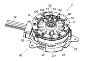
図3は、本実施形態に係るモータ2の概略斜視図である。図4は、本実施形態に係るモータ2の概略断面図である。図4は中心軸Aを含む縦断面図である。モータ2は、インナーロータ型のモータである。モータ2は、ロータ10と、ステータ20と、軸受部30と、ホルダ40とを有する。
FIG. 3 is a schematic perspective view of the motor 2 according to the present embodiment. FIG. 4 is a schematic cross-sectional view of the motor 2 according to the present embodiment. FIG. 4 is a longitudinal sectional view including the central axis A. The motor 2 is an inner rotor type motor. The motor 2 includes a rotor 10, a stator 20, a bearing portion 30, and a holder 40. *
ロータ10は、中心軸Aを中心として回転する。ロータ10は、ロータコア11と、複数の磁石12と、樹脂部13とを有する。本実施形態では、ロータコア11は、複数の磁性鋼板が積層されて形成される。なお、ロータコア11は、複数のコアピースを接合して形成されてもよく、圧粉磁心であってもよい。ロータコア11は、軸方向に貫通する複数の貫通孔11aを有する。インペラ3の回転に伴って、複数の貫通孔11a内を空気が流れる。これにより、モータ2を冷却することができる。また、ロータコア11が貫通孔11aを有することにより、ロータコア11の重量が軽くなり、モータ2の効率を向上させることができる。複数の磁石12は、永久磁石である。
The rotor 10 rotates about the central axis A. The rotor 10 includes a rotor core 11, a plurality of magnets 12, and a resin portion 13. In this embodiment, the rotor core 11 is formed by laminating a plurality of magnetic steel plates. The rotor core 11 may be formed by joining a plurality of core pieces, or may be a dust core. The rotor core 11 has a plurality of through holes 11a penetrating in the axial direction. As the impeller 3 rotates, air flows through the plurality of through holes 11a. Thereby, the motor 2 can be cooled. Further, since the rotor core 11 has the through holes 11a, the weight of the rotor core 11 is reduced, and the efficiency of the motor 2 can be improved. The plurality of magnets 12 are permanent magnets. *
樹脂部13は、ロータコア11の少なくとも一部を覆う。樹脂部13は、複数の磁石12の少なくとも一部を覆う。樹脂部13は、複数の磁石12をロータコア11に対して固定することができる。ただし、複数の磁石12のロータコア11への固定には、樹脂部13以外が用いられてもよい。複数の磁石12は、例えば接着剤によって、ロータ10に対して固定されてよい。
The resin portion 13 covers at least a part of the rotor core 11. The resin portion 13 covers at least a part of the plurality of magnets 12. The resin portion 13 can fix the plurality of magnets 12 to the rotor core 11. However, other than the resin portion 13 may be used to fix the plurality of magnets 12 to the rotor core 11. The plurality of magnets 12 may be fixed to the rotor 10 with an adhesive, for example. *
ステータ20は、ロータ10の径方向外側に位置する。ステータ20は、ステータコア21と、インシュレータ22と、コイル23とを有する。本実施形態では、ステータコア21は、複数の磁性鋼板が積層されて形成される。ただし、ステータコア21は、複数のコアピースを接合して形成されてもよい。ステータコア21の内周面は、ロータ10の外周面と対向する。ステータコア21は、円環状のコアバック211と、コアバック211から径方向内側に突出する複数のティース212とを有する。複数のティース212は、周方向に等間隔に配列される。複数のティース212は、インシュレータ22によって覆われる。インシュレータ22は、絶縁部材(例えば、樹脂など)である。コイル23は、インシュレータ22を介して各ティース212に導線が巻かれることにより形成される。
The stator 20 is located on the radially outer side of the rotor 10. The stator 20 includes a stator core 21, an insulator 22, and a coil 23. In the present embodiment, the stator core 21 is formed by laminating a plurality of magnetic steel plates. However, the stator core 21 may be formed by joining a plurality of core pieces. The inner peripheral surface of the stator core 21 faces the outer peripheral surface of the rotor 10. The stator core 21 has an annular core back 211 and a plurality of teeth 212 protruding radially inward from the core back 211. The plurality of teeth 212 are arranged at equal intervals in the circumferential direction. The plurality of teeth 212 are covered by the insulator 22. The insulator 22 is an insulating member (for example, resin). The coil 23 is formed by winding a conductive wire around each tooth 212 via the insulator 22. *
少なくとも1つの軸受部30は、ロータ10をステータ20に対して回転可能に支持する。本実施形態では、モータは、2つの軸受部30を有する。本実施形態では、各軸受部30は、玉軸受であり、軸方向に間隔をあけて配置される。樹脂部13は、径方向内側に軸受部30を保持する少なくとも1つの軸受保持部13aを有する。本実施形態では、軸受保持部13aの数は、軸受部30の数と同じであり、軸受保持部13aの数は2つである。詳細には、軸受保持部13aは、樹脂部13の軸方向一方側と他方側とに間隔をあけて、それぞれ設けられる。なお、軸受部30は、玉軸受以外の種類の軸受であってもよい。例えば、軸受部30は、スリーブ軸受や流体動圧軸受などであってもよい。
The at least one bearingportion 30 supports the rotor 10 so as to be rotatable with respect to the stator 20. In the present embodiment, the motor has two bearing portions 30. In this embodiment, each bearing part 30 is a ball bearing, and is arrange | positioned at intervals in the axial direction. The resin portion 13 has at least one bearing holding portion 13a that holds the bearing portion 30 on the radially inner side. In the present embodiment, the number of bearing holding portions 13a is the same as the number of bearing portions 30, and the number of bearing holding portions 13a is two. Specifically, the bearing holding portion 13 a is provided on the one side and the other side in the axial direction of the resin portion 13 with a space therebetween. The bearing unit 30 may be a type of bearing other than a ball bearing. For example, the bearing portion 30 may be a sleeve bearing or a fluid dynamic pressure bearing.
The at least one bearing
ホルダ40はステータ20を支持する。ホルダ40は、軸方向他方側に配置されるブラケット50を有する。軸方向からの平面視において、ブラケット50の形状は、略円形状である。ブラケット50の中央部には、軸方向に延びるシャフト41が固定される。軸方向からの平面視において、シャフト41の中心は、中心軸Aと一致する。軸受部30はロータ10とシャフト41の間に位置し、ロータ10はシャフト41に対して回転可能に設けられる。
Theholder 40 supports the stator 20. The holder 40 has a bracket 50 disposed on the other side in the axial direction. In plan view from the axial direction, the shape of the bracket 50 is substantially circular. A shaft 41 extending in the axial direction is fixed to the central portion of the bracket 50. In the plan view from the axial direction, the center of the shaft 41 coincides with the central axis A. The bearing portion 30 is located between the rotor 10 and the shaft 41, and the rotor 10 is provided to be rotatable with respect to the shaft 41.
The
ブラケット50の軸方向他方側には、制御部70が配置される。制御部70は、制御回路を含む制御基板71を有する。本実施形態では、制御基板71は、中心軸Aに対して垂直に配置される。なお、制御基板71は、中心軸Aに対して傾斜してもよい。制御基板71には、複数のワイヤ72が電気的に接続される。複数のワイヤ72は、ブラケット50から径方向外方に引き出される。制御基板71の軸方向他方側には、蓋80が配置される。蓋80は、制御基板71を覆う。蓋80は、ブラケット50に支持される。
A control unit 70 is disposed on the other axial side of the bracket 50. The control unit 70 includes a control board 71 including a control circuit. In the present embodiment, the control board 71 is disposed perpendicular to the central axis A. The control board 71 may be inclined with respect to the central axis A. A plurality of wires 72 are electrically connected to the control board 71. The plurality of wires 72 are drawn out radially outward from the bracket 50. A lid 80 is disposed on the other axial side of the control board 71. The lid 80 covers the control board 71. The lid 80 is supported by the bracket 50. *
ホルダ40は、軸方向一方側に配置されるカバー60を有する。本実施形態では、カバー60は、円形のリング状部材である。なお、カバー60の形状は、多角形であってもよく、特に限定されるものではない。平面視において、カバー60は、ロータ10の径方向外側に配置され、ステータ20の軸方向一方側に配置される。カバー60は、コイル23を覆う。ロータ10は、カバー60よりも軸方向一方側に突出する少なくとも1つの突出部130を有する。突出部130には、インペラ3の筒状部4が取り付けられる。これにより、ロータ10の回転とともに、インペラ3が回転することができる。本実施形態では、突出部130と筒状部4とは、ネジ7によって固定される。ただし、突出部130は筒状部4と、他の手法で固定されてよく、例えば溶着や接着などによって固定されてもよい。インペラ3のロータ10に対する取り付けが突出部130を介して行われるために、インペラ3とロータ10の間には、空気が流れる空間が形成される。
<3.ロータの詳細>
Theholder 40 has a cover 60 arranged on one side in the axial direction. In the present embodiment, the cover 60 is a circular ring-shaped member. The shape of the cover 60 may be a polygon and is not particularly limited. In plan view, the cover 60 is disposed on the radially outer side of the rotor 10 and is disposed on one axial side of the stator 20. The cover 60 covers the coil 23. The rotor 10 has at least one protrusion 130 that protrudes to the one side in the axial direction from the cover 60. The cylindrical portion 4 of the impeller 3 is attached to the protruding portion 130. Thereby, the impeller 3 can rotate with the rotation of the rotor 10. In the present embodiment, the protruding portion 130 and the cylindrical portion 4 are fixed by the screw 7. However, the protruding portion 130 may be fixed to the cylindrical portion 4 by other methods, for example, may be fixed by welding or adhesion. Since the impeller 3 is attached to the rotor 10 via the protrusion 130, a space through which air flows is formed between the impeller 3 and the rotor 10.
<3. Details of rotor>
<3.ロータの詳細>
The
<3. Details of rotor>
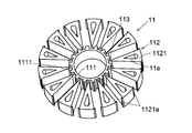
図5は、本実施形態に係るロータコア11の概略斜視図である。ロータコア11は、内コア部111と、外コア部112と、複数の連結部113とを有する。内コア部111は、軸方向に延びる環状部材である。外コア部112は、内コア部111に対して径方向外側に配置される。
FIG. 5 is a schematic perspective view of the rotor core 11 according to the present embodiment. The rotor core 11 has an inner core part 111, an outer core part 112, and a plurality of connecting parts 113. The inner core portion 111 is an annular member that extends in the axial direction. The outer core portion 112 is disposed on the radially outer side with respect to the inner core portion 111. *
外コア部112は、複数の外コア要素1121を有する。軸方向からの平面視において、各外コア要素1121の形状は、略扇形状であり、径方向外側から径方向内側に向けて先細りとなる形状である。すなわち、外コア要素1121の周方向の幅は、径方向内側に向かうにつれて徐々に狭くなる。複数の外コア要素1121は、内コア部111の外周側に、周方向に等間隔で配列される。本実施形態では、外コア要素1121の数は14個である。しかしながら、外コア要素1121の数は適宜変更されてよい。
The outer core part 112 has a plurality of outer core elements 1121. In a plan view from the axial direction, the shape of each outer core element 1121 is a substantially fan shape, and is a shape that tapers from the radially outer side toward the radially inner side. That is, the circumferential width of the outer core element 1121 gradually decreases as it goes radially inward. The plurality of outer core elements 1121 are arranged at equal intervals in the circumferential direction on the outer peripheral side of the inner core portion 111. In the present embodiment, the number of outer core elements 1121 is 14. However, the number of outer core elements 1121 may be changed as appropriate. *
各連結部113は、径方向に延びて、1つの外コア要素1121と内コア部111とを連結する。連結部113は、外コア要素1121の径方向内側の端部の周方向中央と、内コア部111の外周面とを繋ぐ。周方向における各連結部113の幅は、狭いことが好ましい。これにより、磁束が内コア部111へと流れることを抑制することができる。内コア部111、外コア部112及び複数の連結部113は、一繋がりの部材である。
Each connecting portion 113 extends in the radial direction and connects one outer core element 1121 and the inner core portion 111. The connecting portion 113 connects the circumferential center of the radially inner end of the outer core element 1121 and the outer peripheral surface of the inner core portion 111. The width of each connecting portion 113 in the circumferential direction is preferably narrow. Thereby, it can suppress that magnetic flux flows into the inner core part 111. FIG. The inner core portion 111, the outer core portion 112, and the plurality of connecting portions 113 are a single member. *
各外コア要素1121は、軸方向に貫通する貫通孔11aを有する。貫通孔11aは、径方向に拡がる。貫通孔11aは、径方向外側に向かうにつれて周方向の幅が広くなる部分を有する。本実施形態では、軸方向からの平面視において、貫通孔11aは、略扇形状である。このため、外コア要素1121から内コア部111へと流れる磁束の量を抑制することができる。貫通孔11aの体積が大きくなると、当該孔を通過する空気の量を増やすことができ、モータ1をより冷却することができる。
Each outer core element 1121 has a through hole 11a penetrating in the axial direction. The through hole 11a extends in the radial direction. The through-hole 11a has a portion whose width in the circumferential direction increases toward the outer side in the radial direction. In the present embodiment, the through hole 11a has a substantially fan shape in plan view from the axial direction. For this reason, the quantity of the magnetic flux which flows from the outer core element 1121 to the inner core part 111 can be suppressed. When the volume of the through hole 11a is increased, the amount of air passing through the hole can be increased, and the motor 1 can be further cooled. *
図6は、本実施形態に係るロータコア11及び複数の磁石12の概略斜視図である。複数の磁石12は、それぞれ略同一形状であり、略同一サイズである。本実施形態では、各磁石12は略直方体形状である。各磁石12は、2つの外コア要素1121の間の隙間に配置される。ロータコア11において、複数の磁石12は、周方向に等間隔で配列される。本実施形態では、磁石12の数は14個である。しかしながら、磁石12の数は適宜変更されてよい。各磁石12の軸方向一方側および軸方向他方側の端部の少なくともいずれか一方は、軸方向において、ロータコア11の端面から突出する。本実施形態では、磁石12の軸方向一方側の端面が、ロータコア11の上面よりも軸方向上側に、位置する。磁石12の軸方向他方側の端面が、ロータコア11の下面よりも軸方向下側に、位置する。これにより、ロータコア11の重量増加を抑制しつつ、磁石12の体積を大きくして磁力を増加させることができる。
FIG. 6 is a schematic perspective view of the rotor core 11 and the plurality of magnets 12 according to the present embodiment. The plurality of magnets 12 have substantially the same shape and substantially the same size. In the present embodiment, each magnet 12 has a substantially rectangular parallelepiped shape. Each magnet 12 is disposed in a gap between the two outer core elements 1121. In the rotor core 11, the plurality of magnets 12 are arranged at equal intervals in the circumferential direction. In the present embodiment, the number of magnets 12 is 14. However, the number of magnets 12 may be changed as appropriate. At least one of the end portions on the one axial side and the other axial side of each magnet 12 protrudes from the end surface of the rotor core 11 in the axial direction. In the present embodiment, the end surface on the one side in the axial direction of the magnet 12 is positioned on the upper side in the axial direction from the upper surface of the rotor core 11. The end surface of the magnet 12 on the other side in the axial direction is located on the lower side in the axial direction than the lower surface of the rotor core 11. Thereby, the magnetic force can be increased by increasing the volume of the magnet 12 while suppressing the increase in the weight of the rotor core 11. *
本実施形態では、各磁石12は、周方向一方側がN極である主面と、周方向の他方側がS極である主面と、を有する。複数の磁石12は、周方向に同極が対向する向きに配置される。なお、複数の磁石12は、それぞれ、N極とS極が径方向に対向する向きに配置されてもよい。
In the present embodiment, each magnet 12 has a main surface whose one side in the circumferential direction is an N pole and a main surface whose other side in the circumferential direction is an S pole. The plurality of magnets 12 are arranged in the direction in which the same poles face in the circumferential direction. The plurality of magnets 12 may be arranged in directions in which the N pole and the S pole face each other in the radial direction. *
内コア部111は、外周面に径方向外側に突出する複数の第1の凸部1111を有する。複数の第1の凸部1111は、周方向に等間隔に配列される。各第1の凸部1111は、2つの連結部113の間に位置する。各外コア要素1121は、径方向外側の端部において、周方向に突出する一対の第2の凸部1121aを有する。各磁石12の径方向内側の端面は、第1の凸部1111に当たる。各磁石12の径方向外側の端面は、第2の凸部1121aに当たる。各磁石12の主面は、外コア要素1121と周方向に接触する。これにより、ロータコア11において、各磁石12における径方向及び周方向の位置決めが、なされる。
The inner core portion 111 has a plurality of first convex portions 1111 protruding outward in the radial direction on the outer peripheral surface. The plurality of first protrusions 1111 are arranged at equal intervals in the circumferential direction. Each first convex portion 1111 is located between the two connecting portions 113. Each outer core element 1121 has a pair of second convex portions 1121a protruding in the circumferential direction at the radially outer end. The end surface on the radially inner side of each magnet 12 hits the first convex portion 1111. The end surface on the radially outer side of each magnet 12 hits the second convex portion 1121a. The main surface of each magnet 12 is in contact with the outer core element 1121 in the circumferential direction. Thereby, in the rotor core 11, the radial direction and the circumferential direction positioning in each magnet 12 are made. *
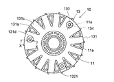
図7は、本実施形態に係るロータ10を軸方向一方側から斜めに見た概略斜視図である。図4及び図7に示すように、樹脂部13は、ロータコア11の軸方向一方側の端面の少なくとも一部を覆う第1樹脂部131を、有する。本実施形態では、第1樹脂部131は、ロータコア11の軸方向一方側の端面の一部及び複数の磁石12の軸方向一方側の端面を覆う。
FIG. 7 is a schematic perspective view of the rotor 10 according to the present embodiment viewed obliquely from one axial side. As shown in FIGS. 4 and 7, the resin portion 13 includes a first resin portion 131 that covers at least a part of the end surface on one axial side of the rotor core 11. In the present embodiment, the first resin portion 131 covers a part of the end surface on one axial side of the rotor core 11 and the end surface on one axial side of the plurality of magnets 12. *
第1樹脂部131は、略円環状である。第1樹脂部131の径方向外側には、複数の間隙131aが形成されている。間隙131aは、第1樹脂部131を軸方向に貫通する。軸方向から見たときに、間隙131aの開口131bの外形は略扇状である。周方向において、少なくとも1つの間隙131aの位置は、少なくとも1つの貫通孔11aの位置と、略同じである。すなわち、軸方向から見たときに、貫通孔11aは、第1樹脂部131に覆われることなく露出する。なお、本実施形態では、外周側に間隙131aを形成したが、これは例示にすぎない。第1樹脂部131は、外周側において切り欠きが周方向に複数配列される形状であってもよい。
The first resin portion 131 is substantially annular. A plurality of gaps 131 a are formed on the radially outer side of the first resin portion 131. The gap 131a penetrates the first resin portion 131 in the axial direction. When viewed from the axial direction, the outer shape of the opening 131b of the gap 131a is substantially fan-shaped. In the circumferential direction, the position of at least one gap 131a is substantially the same as the position of at least one through hole 11a. That is, when viewed from the axial direction, the through hole 11 a is exposed without being covered by the first resin portion 131. In the present embodiment, the gap 131a is formed on the outer peripheral side, but this is merely an example. The first resin portion 131 may have a shape in which a plurality of notches are arranged in the circumferential direction on the outer peripheral side. *
本実施形態では、複数の貫通孔11aのうちの一部は、第1樹脂部131によって覆われる。詳細には、14個の貫通孔11aのうち、2つの貫通孔11aが、第1樹脂部131によって覆われる。換言すると、12個の貫通孔11aは、第1樹脂部131に覆われることなく露出する。第1樹脂部131によって覆われる貫通孔11aの軸方向一方側には、間隙131aが形成されない。
In the present embodiment, a part of the plurality of through holes 11 a is covered with the first resin portion 131. Specifically, of the 14 through holes 11 a, two through holes 11 a are covered with the first resin portion 131. In other words, the twelve through holes 11 a are exposed without being covered by the first resin portion 131. A gap 131a is not formed on one side in the axial direction of the through hole 11a covered by the first resin portion 131. *
第1樹脂部131の径方向外側には、複数の幅狭部131cと複数の幅広部131dとが形成される。幅狭部131cと幅広部131dとは、それぞれ、隣り合う2つの間隙131aに挟まれる部分である。幅狭部131cの周方向の幅は、幅広部131dの周方向の幅と異なる。幅広部131dの周方向の幅は、幅狭部131cの周方向の幅よりも広い。本実施形態では、幅狭部131cの数は、10個である。幅広部131dの数は、2つである。2つの幅広部131dは、周方向に連続して配列される7つの幅狭部131cと、周方向に連続して配列される3つの幅狭部131cとの間に位置する。
A plurality ofnarrow portions 131 c and a plurality of wide portions 131 d are formed on the radially outer side of the first resin portion 131. The narrow portion 131c and the wide portion 131d are portions sandwiched between two adjacent gaps 131a. The width in the circumferential direction of the narrow portion 131c is different from the width in the circumferential direction of the wide portion 131d. The width in the circumferential direction of the wide portion 131d is wider than the width in the circumferential direction of the narrow portion 131c. In the present embodiment, the number of narrow portions 131c is ten. The number of wide portions 131d is two. The two wide portions 131d are located between the seven narrow portions 131c arranged continuously in the circumferential direction and the three narrow portions 131c arranged continuously in the circumferential direction.
A plurality of
第1樹脂部131は、径方向内側に軸方向一方側に向けて伸びる筒状樹脂部1311を有する。軸方向一方側に位置する軸受部30は、筒状樹脂部1311内に圧入される。筒状樹脂部1311は軸受保持部13aを構成する。
Thefirst resin portion 131 has a cylindrical resin portion 1311 that extends radially inward toward one side in the axial direction. The bearing portion 30 located on one side in the axial direction is press-fitted into the cylindrical resin portion 1311. The cylindrical resin portion 1311 constitutes a bearing holding portion 13a.
The
第1樹脂部131は、軸方向一方側に突出する少なくとも1つの突出部130を有する。本実施形態では、突出部130の数は、3つである。3つの突出部130は、周方向に等間隔に配列される。3つの突出部130のうち、1つの突出部130は複数の幅狭部131cの1つに形成され、残り2つの突出部130は2つの幅広部131dにそれぞれ形成される。幅狭部131cに形成される突出部130は、軸方向からの平面視において磁石12に重なる。幅広部131dに形成される突出部130は、軸方向からの平面視において貫通孔11aに重なる。言い換えると、周方向において、幅狭部131cに形成される突出部130の位置は、複数の磁石12のうちの1つの位置と、略同じである。本実施形態では、突出部130は円柱状である。突出部130は、中央部に軸方向に延びる孔130aを有する。孔130aは、ネジ孔である。なお、突出部130の数、配置及び形状は例示であり、これらは適宜変更されてよい。
The first resin portion 131 has at least one protrusion 130 that protrudes to one axial side. In the present embodiment, the number of protrusions 130 is three. The three protrusions 130 are arranged at equal intervals in the circumferential direction. Of the three protrusions 130, one protrusion 130 is formed in one of the plurality of narrow portions 131c, and the remaining two protrusions 130 are formed in two wide portions 131d, respectively. The protruding portion 130 formed in the narrow portion 131c overlaps the magnet 12 in plan view from the axial direction. The protruding portion 130 formed in the wide portion 131d overlaps the through hole 11a in a plan view from the axial direction. In other words, in the circumferential direction, the position of the protruding portion 130 formed in the narrow portion 131 c is substantially the same as the position of one of the plurality of magnets 12. In the present embodiment, the projecting portion 130 is cylindrical. The protrusion 130 has a hole 130a extending in the axial direction at the center. The hole 130a is a screw hole. In addition, the number, arrangement | positioning, and shape of the protrusion part 130 are illustrations, These may be changed suitably. *
図8は、本実施形態に係るロータ10を軸方向他方側から斜めに見た概略斜視図である。樹脂部13は、ロータコア11の軸方向他方側の端面の少なくとも一部を覆う第2樹脂部132を有する。本実施形態では、第2樹脂部132は、ロータコア11の軸方向他方側の端面の一部及び複数の磁石12の軸方向他方側の端面を覆う。
FIG. 8 is a schematic perspective view of the rotor 10 according to the present embodiment viewed obliquely from the other axial side. The resin portion 13 includes a second resin portion 132 that covers at least a part of the end surface on the other axial side of the rotor core 11. In the present embodiment, the second resin portion 132 covers a part of the end surface on the other axial side of the rotor core 11 and the end surface on the other axial side of the plurality of magnets 12. *
第2樹脂部132は、略円環状である。第2樹脂部132は、複数の間隙132aを有する。間隙132aは、第2樹脂部132を軸方向に貫通する。軸方向から見たときに、間隙132aの開口132bの外形は略扇状である。周方向において、少なくとも1つの間隙132aの位置は、少なくとも1つの貫通孔11aの位置と、略同じである。すなわち、軸方向から見たときに、貫通孔11aは、第2樹脂部132に覆われることなく露出する。間隙132aは、第1の樹脂部131の間隙131aと軸方向に対向する位置に設けられる。言い換えると、周方向において、間隙132aの位置は、間隙131aの位置と、同じである。14個の貫通孔11aのうち、2つの貫通孔11aが第2樹脂部132によって覆われる。12個の貫通孔11aは、第2樹脂部132に覆われることなく、露出する。
The second resin portion 132 is substantially annular. The second resin portion 132 has a plurality of gaps 132a. The gap 132a penetrates the second resin portion 132 in the axial direction. When viewed from the axial direction, the outer shape of the opening 132b of the gap 132a is substantially fan-shaped. In the circumferential direction, the position of at least one gap 132a is substantially the same as the position of at least one through hole 11a. That is, when viewed from the axial direction, the through hole 11 a is exposed without being covered by the second resin portion 132. The gap 132a is provided at a position facing the gap 131a of the first resin portion 131 in the axial direction. In other words, in the circumferential direction, the position of the gap 132a is the same as the position of the gap 131a. Of the 14 through holes 11 a, two through holes 11 a are covered with the second resin portion 132. The twelve through holes 11 a are exposed without being covered with the second resin portion 132. *
第1実施形態と同様に、第2樹脂部132は、複数の幅狭部132cと複数の幅広部132dを有する。複数の幅狭部132cと複数の幅広部132dとは、第2樹脂部132の径方向外側に形成される。幅狭部132cと幅広部132dとは、それぞれ、隣り合う2つの間隙132aに挟まれる部分である。幅狭部132cの周方向の幅は、幅広部132dの周方向の幅と異なる。幅広部132dの周方向の幅は、幅狭部132cの周方向の幅より広い。幅狭部132c及び幅広部132dは、第1樹脂部131の幅狭部131c及び幅広部131dに軸方向に対向する位置に設けられる。言い換えると、周方向において、幅狭部132cの位置は、幅狭部131cの位置と同じである。周方向において、幅広部132dの位置は、幅広部131dの位置と、同じである。本実施形態において、幅狭部132cの数は10個である。幅広部132dの数は2つである。
Similar to the first embodiment, the second resin portion 132 has a plurality of narrow portions 132c and a plurality of wide portions 132d. The plurality of narrow portions 132 c and the plurality of wide portions 132 d are formed on the radially outer side of the second resin portion 132. The narrow portion 132c and the wide portion 132d are portions sandwiched between two adjacent gaps 132a. The width in the circumferential direction of the narrow portion 132c is different from the width in the circumferential direction of the wide portion 132d. The width in the circumferential direction of the wide portion 132d is wider than the width in the circumferential direction of the narrow portion 132c. The narrow portion 132c and the wide portion 132d are provided at positions facing the narrow portion 131c and the wide portion 131d of the first resin portion 131 in the axial direction. In other words, in the circumferential direction, the position of the narrow part 132c is the same as the position of the narrow part 131c. In the circumferential direction, the position of the wide part 132d is the same as the position of the wide part 131d. In the present embodiment, the number of the narrow portions 132c is ten. The number of wide portions 132d is two. *
第2樹脂部132は、軸方向他方側に突出する少なくとも1つのリブ1321を有する。これにより、インペラ3が回転する際に発生する空気の流れを変えることができ、貫通孔11a内を通過する空気の量を増やすことができる。本実施形態において、リブ1321は四角柱状である。なお、リブ1321の形状は、多角形柱、円柱、板状などであってもよく、特に限定されるものではない。軸方向から見たときに、リブ1321は、径方向に対して斜めに延びる。リブ1321は、第2樹脂部132の径方向外周側に配置される。本実施形態では、リブ1321は複数形成される。複数のリブ1321は、周方向に等間隔に配置される。本実施形態では、各幅狭部132cに1つのリブ1321が設けられ、各幅広部132dに2つのリブ1321が設けられる。リブ1321の径方向外側の端部は、円環状に設けられる第2樹脂部132の外周面より径方向外方に突出する。
The second resin portion 132 has at least one rib 1321 protruding to the other side in the axial direction. Thereby, the flow of the air generated when the impeller 3 rotates can be changed, and the amount of air passing through the through hole 11a can be increased. In the present embodiment, the rib 1321 has a quadrangular prism shape. In addition, the shape of the rib 1321 may be a polygonal column, a cylinder, a plate shape, or the like, and is not particularly limited. When viewed from the axial direction, the rib 1321 extends obliquely with respect to the radial direction. The rib 1321 is disposed on the radially outer peripheral side of the second resin portion 132. In the present embodiment, a plurality of ribs 1321 are formed. The plurality of ribs 1321 are arranged at equal intervals in the circumferential direction. In the present embodiment, one rib 1321 is provided for each narrow portion 132c, and two ribs 1321 are provided for each wide portion 132d. The radially outer end of the rib 1321 protrudes radially outward from the outer peripheral surface of the second resin portion 132 provided in an annular shape. *
各リブ1321は、周方向に複数配列される貫通孔11aと隣り合う。軸方向からの平面視において、リブ1321は、径方向外側から径方向内側に向かうにつれて、ロータ10の回転方向前方に位置する貫通孔11aに近づく。これにより、ロータ10が回転する際に発生する空気の流れを各貫通孔11aに向かわせることができる。すなわち、貫通孔11a内をより多くの空気が通過することができ、モータ1の内部をより冷却することができる。本実施形態では、各貫通孔11aに対してインペラ3は、図1において反時計回り方向に回転する。すなわち、ロータ10は、図8において時計回り方向に回転する。この場合、ロータ10とともに回転するインペラ3により、空気も時計回り方向に向かって流れる。図8においては、上述した回転方向前方に位置する貫通孔11aとは、時計回り側に位置する貫通孔11aである。図8において、リブ1321は、径方向外側から内側に向かうにつれて、左隣に位置する貫通孔11aに近づいている。なお、ロータ10の回転方向が本実施形態とは逆方向である場合、リブ1321が傾く方向は逆になる。図8において、ロータ10の回転方向が反時計回りである場合には、上述した回転方向前方に位置する貫通孔11aとは、反時計回り側に位置する貫通孔11aである。この場合、リブ1321は、径方向外側から内側に向かうにつれて、右隣に位置する貫通孔11aに近づく。
Each rib 1321 is adjacent to a plurality of through holes 11a arranged in the circumferential direction. In a plan view from the axial direction, the rib 1321 approaches the through hole 11a located forward in the rotational direction of the rotor 10 from the radially outer side toward the radially inner side. Thereby, the flow of air generated when the rotor 10 rotates can be directed to each through hole 11a. That is, more air can pass through the through hole 11a, and the interior of the motor 1 can be further cooled. In the present embodiment, the impeller 3 rotates counterclockwise in FIG. 1 with respect to each through hole 11a. That is, the rotor 10 rotates in the clockwise direction in FIG. In this case, the air also flows in the clockwise direction by the impeller 3 that rotates together with the rotor 10. In FIG. 8, the above-described through hole 11 a positioned forward in the rotational direction is the through hole 11 a positioned on the clockwise side. In FIG. 8, the rib 1321 approaches the through-hole 11a located on the left side as it goes from the radially outer side to the inner side. In addition, when the rotation direction of the rotor 10 is the reverse direction to the present embodiment, the direction in which the rib 1321 is inclined is reversed. In FIG. 8, when the rotation direction of the rotor 10 is counterclockwise, the above-described through hole 11a positioned forward in the rotation direction is the through hole 11a positioned on the counterclockwise side. In this case, the rib 1321 approaches the through hole 11a located on the right side as it goes from the radially outer side to the inner side. *
リブ1321の数は、樹脂部13からずれた位置に配置されて露出している貫通孔11aの数以上である。本実施形態では、ロータコア11に形成される14個の貫通孔11aのうち、12個の貫通孔11aは、第1樹脂部131及び第2樹脂部132に覆われることなく、露出する。すなわち、ロータ10は、樹脂部13からずれた位置に配置されて露出される貫通孔11aを12個有する。一方、リブ1321の数は14個であり、リブ1321の数は露出されている貫通孔11aの数より多い。これにより、リブ1321が所定の方向により多くの空気を向かわせることができ、貫通孔11aに多くの空気を送り込むことができる。このために、モータ2をより冷却することができる。
The number of ribs 1321 is equal to or greater than the number of through holes 11 a that are arranged and exposed at positions shifted from the resin portion 13. In the present embodiment, of the 14 through holes 11 a formed in the rotor core 11, 12 through holes 11 a are exposed without being covered by the first resin portion 131 and the second resin portion 132. That is, the rotor 10 has twelve through holes 11 a that are arranged and exposed at positions displaced from the resin portion 13. On the other hand, the number of ribs 1321 is 14, and the number of ribs 1321 is larger than the number of exposed through holes 11a. As a result, the rib 1321 can direct more air in a predetermined direction, and more air can be sent into the through hole 11a. For this reason, the motor 2 can be further cooled. *
図4に示すように、樹脂部13は、径方向内周側に、ロータコア11の内周面を覆う第3樹脂部133を有する。第3樹脂部133は、第1樹脂部131と第2樹脂部132とを連結する。第3樹脂部133の軸方向他方側の端部には、軸方向他方側に配置される軸受部30を保持する軸受保持部13aが形成される。樹脂部13は、ロータコア11及び磁石12の外周面を覆うのが好ましい。これにより、ロータ10の回転時において、磁石12がロータ10から飛散することを防止することができる。
As shown in FIG. 4, the resin portion 13 has a third resin portion 133 that covers the inner peripheral surface of the rotor core 11 on the radially inner peripheral side. The third resin portion 133 connects the first resin portion 131 and the second resin portion 132. A bearing holding portion 13 a that holds the bearing portion 30 disposed on the other side in the axial direction is formed at the end portion on the other side in the axial direction of the third resin portion 133. The resin portion 13 preferably covers the outer peripheral surfaces of the rotor core 11 and the magnet 12. Thereby, it is possible to prevent the magnet 12 from scattering from the rotor 10 when the rotor 10 rotates. *
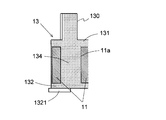
図9は、本実施形態に係るロータ10を軸方向一方側から見た概略平面図である。図10は、図9のX-X位置における概略断面図である。図9及び図10に示すように、樹脂部13は延出部134を有する。延出部134は、複数の貫通孔11aのうちの少なくとも一つに設けられる。延出部134は、第1樹脂部131から貫通孔11a内を軸方向に延びる。なお、図9においては、第1樹脂部131に覆われて見えない貫通孔11a及び延出部134が破線で示されている。
FIG. 9 is a schematic plan view of the rotor 10 according to the present embodiment as viewed from one side in the axial direction. FIG. 10 is a schematic cross-sectional view taken along the line XX in FIG. As shown in FIGS. 9 and 10, the resin portion 13 has an extending portion 134. The extension part 134 is provided in at least one of the plurality of through holes 11a. The extending portion 134 extends from the first resin portion 131 in the through hole 11a in the axial direction. In FIG. 9, the through-hole 11 a and the extension part 134 that are covered with the first resin part 131 and are not visible are indicated by broken lines. *
本実施形態では、延出部134は2つの貫通孔11aに設けられる。この2つの貫通孔11aは、第1樹脂部131の幅広部131dに覆われる。本実施形態では、延出部134の少なくとも一部は、軸方向に垂直な方向において、貫通孔11aを構成する内側面と、対向または接触する。すなわち、軸方向からの平面視において、延出部134と貫通孔11aの外形とは、ほぼ同形状および同サイズである。ただし、これは例示であり、軸方向からの平面視において、延出部134は、貫通孔11aの外形と異なる形状であったり、貫通孔11aの外形よりも小さかったりしてもよい。
In this embodiment, the extension part 134 is provided in the two through holes 11a. The two through holes 11 a are covered with the wide portion 131 d of the first resin portion 131. In the present embodiment, at least a part of the extending part 134 faces or contacts the inner side surface constituting the through hole 11a in a direction perpendicular to the axial direction. That is, in the plan view from the axial direction, the extended portion 134 and the outer shape of the through hole 11a have substantially the same shape and the same size. However, this is merely an example, and the extension portion 134 may have a shape different from the outer shape of the through hole 11a or may be smaller than the outer shape of the through hole 11a in plan view from the axial direction. *
図10に示すように、延出部134は、貫通孔11aを通って、第1樹脂部131から第2樹脂部132まで延びる。すなわち、延出部134は、第1樹脂部131と第2樹脂部132を繋ぐ。ただし、これは例示であり、第1樹脂部134から延びる延出部134は、第2樹脂部132まで到達しなくてもよい。すなわち、第1樹脂部131から延びる延出部134の先端部は、貫通孔11a内に位置してもよい。また、延出部134は、貫通孔11aを介して第2樹脂部132から第1樹脂部131まで延びてもよい。この場合も、第2樹脂部132から延びる延出部134は、第1樹脂部131まで到達しなくてもよい。すなわち、第2樹脂部132から伸びる延出部134の先端部が、貫通孔11a内に位置してもよい。
As shown in FIG. 10, the extending part 134 extends from the first resin part 131 to the second resin part 132 through the through hole 11a. That is, the extending part 134 connects the first resin part 131 and the second resin part 132. However, this is merely an example, and the extending part 134 extending from the first resin part 134 may not reach the second resin part 132. That is, the distal end portion of the extending portion 134 extending from the first resin portion 131 may be located in the through hole 11a. Further, the extending part 134 may extend from the second resin part 132 to the first resin part 131 through the through hole 11a. Also in this case, the extending part 134 extending from the second resin part 132 may not reach the first resin part 131. That is, the distal end portion of the extending portion 134 extending from the second resin portion 132 may be located in the through hole 11a. *
図9に示すように、突出部130と延出部134とは、軸方向からの平面視において重なる。本実施形態では、軸方向からの平面視において、突出部130と延出部134とは完全に重なっていない。突出部130の一部は、延出部134からはみ出す。すなわち、周方向または径方向の少なくともいずれか一方において、突出部130の位置は、延出部134の位置からずれる。ただし、軸方向からの平面視において、延出部134は、その全体が貫通孔11aと重なってもよい。すなわち、周方向および径方向において、突出部130の位置が、延出部134の位置と同じであってもよい。
As shown in FIG. 9, the protruding portion 130 and the extending portion 134 overlap in a plan view from the axial direction. In the present embodiment, the protruding portion 130 and the extending portion 134 do not completely overlap in a plan view from the axial direction. A part of the protruding portion 130 protrudes from the extending portion 134. That is, the position of the projecting portion 130 deviates from the position of the extending portion 134 in at least one of the circumferential direction and the radial direction. However, the entire extension portion 134 may overlap with the through hole 11a in a plan view from the axial direction. That is, the position of the protrusion 130 may be the same as the position of the extension 134 in the circumferential direction and the radial direction. *
なお、本実施形態では、軸方向からの平面視において、3つの突出部130のうち、2つの突出部130が延出部134と重なり、残り1つは延出部134とは重ならない。この残り1つの突出部130は、軸方向からの平面視において磁石12と重なる。ただし、これは例示であり、軸方向からの平面視において、複数の突出部130の少なくとも一つが延出部134と重なればよい。軸方向からの平面視において、複数の突出部130の全てが延出部134と重なってもよい。
In the present embodiment, in the plan view from the axial direction, of the three protrusions 130, two protrusions 130 overlap the extension part 134, and the remaining one does not overlap the extension part 134. The remaining one protrusion 130 overlaps the magnet 12 in plan view from the axial direction. However, this is merely an example, and it is only necessary that at least one of the plurality of projecting portions 130 overlaps the extending portion 134 in a plan view from the axial direction. All of the plurality of projecting portions 130 may overlap with the extending portion 134 in a plan view from the axial direction. *
本実施形態において、樹脂部13では、突出部130が設けられる位置において、延出部134によって軸方向の厚みが増す。すなわち、樹脂部13における突出部130が設けられる部分には、延出部134が配置されることから、剛性が増す。延出部134が第1樹脂部131から第2樹脂部132まで延びる。このため、樹脂部13における突出部130が設けられる部分の剛性は、更に増している。突出部130には、インペラ3が取り付けられる。すなわち、本実施形態では、樹脂部13におけるインペラ3が取り付けられる部分の剛性を向上できる。このため、突出部130とインペラ3の固定を、しっかりと行うことができる。この結果、電動ファン1において、ロータ10に対するインペラ3のがたつきを抑制することができる。ロータ10に対するインペラ3のがたつきが抑制されるため、インペラ3のがたつきによって生じる騒音を抑制することができる。また、インペラ3のがたつきが生じ難いために、ロータ10がステータ20に対して位置精度よく回転することができ、電動ファン1の効率を高くすることができる。
In the present embodiment, in the resin portion 13, the axial thickness is increased by the extending portion 134 at the position where the protruding portion 130 is provided. That is, since the extending portion 134 is disposed at a portion of the resin portion 13 where the protruding portion 130 is provided, the rigidity is increased. The extending part 134 extends from the first resin part 131 to the second resin part 132. For this reason, the rigidity of the part in which the protrusion part 130 in the resin part 13 is provided further increases. The impeller 3 is attached to the protrusion 130. That is, in this embodiment, the rigidity of the part to which the impeller 3 is attached in the resin portion 13 can be improved. For this reason, the protrusion 130 and the impeller 3 can be firmly fixed. As a result, in the electric fan 1, rattling of the impeller 3 with respect to the rotor 10 can be suppressed. Since the rattling of the impeller 3 with respect to the rotor 10 is suppressed, noise caused by the rattling of the impeller 3 can be suppressed. Further, since the impeller 3 is unlikely to rattle, the rotor 10 can rotate with respect to the stator 20 with high positional accuracy, and the efficiency of the electric fan 1 can be increased. *
なお、軸方向からの平面視において、突出部130の少なくとも一部は、貫通孔11aの周方向の幅が最も広くなる箇所に重なるのが好ましい。この構成では、樹脂部13の軸方向の厚みが厚くなる部分のうち周方向の幅が広く剛性が増す箇所に、突出部130を配置できる。このために、突出部130とインペラ3の固定をしっかりと行うことができる。
In addition, it is preferable that at least a part of the projecting portion 130 overlap with a portion where the width in the circumferential direction of the through hole 11a is the widest in a plan view from the axial direction. In this configuration, the protruding portion 130 can be disposed at a portion where the circumferential width is wide and rigidity is increased in the portion where the axial thickness of the resin portion 13 is increased. For this reason, the protrusion 130 and the impeller 3 can be firmly fixed. *
<4.変形例>
本実施形態において、モータ2は、樹脂部13によって塞がれない貫通孔11aを複数有する。このために、インペラ3を回転させることによって、貫通孔11a内を軸方向他方側から軸方向一方側に向かう空気が流れる。この空気の流れによってモータ2の内部の冷却を行うことができる。樹脂部13にリブ1321が設けられるために、貫通孔11a内を通過する空気の量を増やして、モータ1を効率良く冷却することができる。すなわち、本実施形態によれば、モータ1において、冷却性能を確保しつつ、インペラ3が取り付けられる部分の剛性を向上させることができる。
<4. Modification>
In the present embodiment, themotor 2 has a plurality of through holes 11 a that are not blocked by the resin portion 13. For this reason, by rotating the impeller 3, air flowing from the other side in the axial direction toward one side in the axial direction flows in the through hole 11a. The inside of the motor 2 can be cooled by this air flow. Since the rib 1321 is provided in the resin portion 13, the amount of air passing through the through hole 11a can be increased, and the motor 1 can be efficiently cooled. That is, according to the present embodiment, in the motor 1, the rigidity of the portion to which the impeller 3 is attached can be improved while ensuring the cooling performance.
本実施形態において、モータ2は、樹脂部13によって塞がれない貫通孔11aを複数有する。このために、インペラ3を回転させることによって、貫通孔11a内を軸方向他方側から軸方向一方側に向かう空気が流れる。この空気の流れによってモータ2の内部の冷却を行うことができる。樹脂部13にリブ1321が設けられるために、貫通孔11a内を通過する空気の量を増やして、モータ1を効率良く冷却することができる。すなわち、本実施形態によれば、モータ1において、冷却性能を確保しつつ、インペラ3が取り付けられる部分の剛性を向上させることができる。
<4. Modification>
In the present embodiment, the
本開示は上述した実施形態に限られず、様々な変形が可能である。例えば、ブラケット50とカバー60とが、別部材ではなく、単一の部材であってよい。シャフト41はブラケット50に固定されなくてもよく、シャフト41がロータ10とともに回転する構造であってもよい。この場合、シャフト41は、例えば、第3樹脂部133に固定されてもよい。軸受部30は、例えば、ブラケット50及びカバー60に固定されてもよい。第2樹脂部132にリブ1321を必ずしも設ける必要はなく、リブ1321は設けられなくてもよい。
The present disclosure is not limited to the above-described embodiments, and various modifications can be made. For example, the bracket 50 and the cover 60 may be a single member instead of separate members. The shaft 41 may not be fixed to the bracket 50, and the shaft 41 may be structured to rotate with the rotor 10. In this case, the shaft 41 may be fixed to the third resin portion 133, for example. The bearing portion 30 may be fixed to the bracket 50 and the cover 60, for example. The rib 1321 is not necessarily provided in the second resin portion 132, and the rib 1321 may not be provided. *
以上に示した実施形態や変形例は、本開示の例示にすぎない。実施形態や変形例の構成は、本開示の技術的思想を超えない範囲で適宜変更されてもよい。また、実施形態や複数の変形例は、可能な範囲で組み合わせて実施されてよい。
The above-described embodiments and modifications are merely examples of the present disclosure. The configurations of the embodiments and the modifications may be changed as appropriate without departing from the technical idea of the present disclosure. Further, the embodiment and the plurality of modified examples may be implemented in combination within a possible range.
本開示の実施形態は、例えば、自動車の冷却水を冷却する電動ファン等に利用することができる。
The embodiment of the present disclosure can be used for, for example, an electric fan that cools cooling water of an automobile.
1・・・電動ファン、2・・・モータ、3・・・インペラ、4・・・筒状部、5・・・円板部、5a・・・ネジ用孔、6・・・円筒部、7・・・ネジ、8・・・羽根、9・・・円環部、10・・・ロータ、11・・・ロータコア、11a・・・貫通孔、12・・・磁石、13・・・樹脂部、13a・・・軸受保持部、20・・・ステータ、21・・・ステータコア、22・・・インシュレータ、23・・・コイル、30・・・軸受部、40・・・ホルダ、41・・・シャフト、50・・・ブラケット、60・・・カバー、70・・・制御部、71・・・制御基板、72・・・ワイヤ、80・・・蓋、111・・・内コア部、112・・・外コア部、113・・・連結部、130・・・突出部、131・・・第1樹脂部、131a・・・間隙、131b・・・開口、131c・・・幅狭部、131d・・・幅広部、132・・・第2樹脂部、132a・・・凹部、132b・・・開口、132c・・・幅狭部、132d・・・幅広部、133・・・第3樹脂部、134・・・延出部、211・・・コアバック、212・・・ティース、1111・・・第1の凸部、1121・・・外コア要素、1121a・・・第2の凸部、1311・・・筒状樹脂部、1321・・・リブ、A・・・中心軸
DESCRIPTION OF SYMBOLS 1 ... Electric fan, 2 ... Motor, 3 ... Impeller, 4 ... Cylindrical part, 5 ... Disk part, 5a ... Screw hole, 6 ... Cylindrical part, DESCRIPTION OF SYMBOLS 7 ... Screw, 8 ... Blade | wing, 9 ... Ring part, 10 ... Rotor, 11 ... Rotor core, 11a ... Through-hole, 12 ... Magnet, 13 ... Resin Part, 13a ... bearing holding part, 20 ... stator, 21 ... stator core, 22 ... insulator, 23 ... coil, 30 ... bearing part, 40 ... holder, 41 ... -Shaft, 50 ... Bracket, 60 ... Cover, 70 ... Control part, 71 ... Control board, 72 ... Wire, 80 ... Cover, 111 ... Inner core part, 112 ... outer core part, 113 ... connecting part, 130 ... projecting part, 131 ... first resin part, 131a ... gap, 31b ... Opening, 131c ... Narrow part, 131d ... Wide part, 132 ... Second resin part, 132a ... Recess, 132b ... Opening, 132c ... Narrow part, 132d: Wide portion, 133 ... Third resin portion, 134 ... Extension portion, 211 ... Core back, 212 ... Teeth, 1111 ... First convex portion, 1121. -Outer core element, 1121a ... 2nd convex part, 1311 ... Cylindrical resin part, 1321 ... Rib, A ... Center axis
Claims (7)
- インナーロータ型のモータであって、
中心軸を中心として回転するロータと、
前記ロータの径方向外側に位置するステータと、
を有し、
前記ロータは、
ロータコアと、
前記ロータコアの少なくとも一部を覆う樹脂部と、
を有し、
前記ロータコアは、軸方向に貫通する複数の貫通孔を有し、
前記樹脂部は、
前記ロータコアの軸方向一方側の端面の少なくとも一部を覆う第1樹脂部と、
前記複数の貫通孔のうち少なくとも一つに設けられており、前記第1樹脂部から前記貫通孔内を軸方向に延びる延出部と、
を有し、
前記第1樹脂部は、軸方向一方側に突出する突出部を有し、
前記突出部と前記延出部とは、軸方向からの平面視において重なる、モータ。
An inner rotor type motor,
A rotor that rotates about a central axis;
A stator located radially outside the rotor;
Have
The rotor is
The rotor core,
A resin portion covering at least a part of the rotor core;
Have
The rotor core has a plurality of through holes penetrating in the axial direction,
The resin part is
A first resin portion covering at least a part of an end face on one axial side of the rotor core;
An extension portion that is provided in at least one of the plurality of through holes, and extends in the axial direction from the first resin portion in the through hole;
Have
The first resin portion has a protruding portion protruding to one side in the axial direction,
The projecting portion and the extending portion overlap each other in plan view from the axial direction.
- 前記樹脂部は、前記ロータコアの軸方向他方側の端面の少なくとも一部を覆う第2樹脂部を有し、
前記延出部は、前記第1樹脂部と前記第2樹脂部を繋ぐ、請求項1に記載のモータ。
The resin portion has a second resin portion that covers at least a part of the end surface on the other axial side of the rotor core,
The motor according to claim 1, wherein the extension part connects the first resin part and the second resin part.
- 前記第2樹脂部は、軸方向他方側に突出するリブを有する、請求項2に記載のモータ。
The motor according to claim 2, wherein the second resin portion has a rib protruding to the other side in the axial direction.
- 軸方向からの平面視において、
前記貫通孔は径方向に拡がり、
前記リブは径方向に対して斜めに延びており、
前記リブは、径方向外側から径方向内側に向かうにつれて、前記ロータの回転方向前方に位置する前記貫通孔に近づく、請求項3に記載のモータ。
In plan view from the axial direction,
The through hole extends in the radial direction,
The rib extends obliquely with respect to the radial direction,
The motor according to claim 3, wherein the rib approaches the through hole located forward in the rotational direction of the rotor as it goes from the radially outer side to the radially inner side.
- 前記リブの数は、前記樹脂部からずれた位置に配置されて露出している前記貫通孔の数以上である、請求項3又は4に記載のモータ。
The number of the said ribs is a motor of Claim 3 or 4 which is more than the number of the said through-holes arrange | positioned and exposed in the position shifted | deviated from the said resin part.
- 前記貫通孔は、径方向外側に向かうにつれて周方向の幅が広くなる部分を有し、
軸方向からの平面視において、前記突出部の少なくとも一部は、前記貫通孔の周方向の幅が最も広くなる箇所に重なる、請求項1から5のいずれか1項に記載のモータ。
The through-hole has a portion whose width in the circumferential direction increases toward the outside in the radial direction,
6. The motor according to claim 1, wherein at least a part of the projecting portion overlaps with a portion where the circumferential width of the through hole is widest in a plan view from the axial direction.
- 請求項1から6のいずれか1項に記載のモータと、
前記突出部を介して前記モータに取り付けられるインペラと、
を有する、電動ファン。 The motor according to any one of claims 1 to 6,
An impeller attached to the motor via the protrusion,
Having an electric fan.
Priority Applications (4)
| Application Number | Priority Date | Filing Date | Title |
|---|---|---|---|
| JP2018508473A JPWO2017169077A1 (en) | 2016-03-31 | 2017-02-01 | motor |
| DE112017001782.3T DE112017001782T5 (en) | 2016-03-31 | 2017-02-01 | engine |
| CN201780020720.6A CN109075661A (en) | 2016-03-31 | 2017-02-01 | Motor |
| US16/148,191 US20190036403A1 (en) | 2016-03-31 | 2018-10-01 | Motor |
Applications Claiming Priority (2)
| Application Number | Priority Date | Filing Date | Title |
|---|---|---|---|
| JP2016070269 | 2016-03-31 | ||
| JP2016-070269 | 2016-03-31 |
Related Child Applications (1)
| Application Number | Title | Priority Date | Filing Date |
|---|---|---|---|
| US16/148,191 Continuation US20190036403A1 (en) | 2016-03-31 | 2018-10-01 | Motor |
Publications (1)
| Publication Number | Publication Date |
|---|---|
| WO2017169077A1 true WO2017169077A1 (en) | 2017-10-05 |
Family
ID=59962842
Family Applications (1)
| Application Number | Title | Priority Date | Filing Date |
|---|---|---|---|
| PCT/JP2017/003548 WO2017169077A1 (en) | 2016-03-31 | 2017-02-01 | Motor |
Country Status (5)
| Country | Link |
|---|---|
| US (1) | US20190036403A1 (en) |
| JP (1) | JPWO2017169077A1 (en) |
| CN (1) | CN109075661A (en) |
| DE (1) | DE112017001782T5 (en) |
| WO (1) | WO2017169077A1 (en) |
Families Citing this family (2)
| Publication number | Priority date | Publication date | Assignee | Title |
|---|---|---|---|---|
| DE102017129212A1 (en) * | 2017-12-08 | 2019-06-13 | Dr. Ing. H.C. F. Porsche Aktiengesellschaft | Rotor with cooling |
| JP7327756B2 (en) * | 2019-05-29 | 2023-08-16 | ニデックテクノモータ株式会社 | rotor and motor |
Citations (6)
| Publication number | Priority date | Publication date | Assignee | Title |
|---|---|---|---|---|
| JPH0397353U (en) * | 1990-01-23 | 1991-10-07 | ||
| JPH07312852A (en) * | 1994-05-13 | 1995-11-28 | Yaskawa Electric Corp | Method for manufacturing permanent magnet type rotor |
| JP2014036457A (en) * | 2012-08-07 | 2014-02-24 | Nippon Densan Corp | Rotor, motor and method for manufacturing rotor |
| US20140191623A1 (en) * | 2011-09-12 | 2014-07-10 | Brose Fahrzeugteile Gmbh & Co. Kommanditgesellschaft, Wuerzburg | Breathing electric motor |
| JP2014150688A (en) * | 2013-02-01 | 2014-08-21 | Aisin Seiki Co Ltd | Rotor and dynamo-electric machine |
| JP2014230348A (en) * | 2013-05-21 | 2014-12-08 | 日本電産株式会社 | Rotor and motor |
Family Cites Families (1)
| Publication number | Priority date | Publication date | Assignee | Title |
|---|---|---|---|---|
| EP2012388B1 (en) * | 2006-04-26 | 2011-12-28 | Murata Manufacturing Co. Ltd. | Article provided with feed circuit board |
-
2017
- 2017-02-01 JP JP2018508473A patent/JPWO2017169077A1/en not_active Withdrawn
- 2017-02-01 WO PCT/JP2017/003548 patent/WO2017169077A1/en active Application Filing
- 2017-02-01 DE DE112017001782.3T patent/DE112017001782T5/en not_active Withdrawn
- 2017-02-01 CN CN201780020720.6A patent/CN109075661A/en not_active Withdrawn
-
2018
- 2018-10-01 US US16/148,191 patent/US20190036403A1/en not_active Abandoned
Patent Citations (6)
| Publication number | Priority date | Publication date | Assignee | Title |
|---|---|---|---|---|
| JPH0397353U (en) * | 1990-01-23 | 1991-10-07 | ||
| JPH07312852A (en) * | 1994-05-13 | 1995-11-28 | Yaskawa Electric Corp | Method for manufacturing permanent magnet type rotor |
| US20140191623A1 (en) * | 2011-09-12 | 2014-07-10 | Brose Fahrzeugteile Gmbh & Co. Kommanditgesellschaft, Wuerzburg | Breathing electric motor |
| JP2014036457A (en) * | 2012-08-07 | 2014-02-24 | Nippon Densan Corp | Rotor, motor and method for manufacturing rotor |
| JP2014150688A (en) * | 2013-02-01 | 2014-08-21 | Aisin Seiki Co Ltd | Rotor and dynamo-electric machine |
| JP2014230348A (en) * | 2013-05-21 | 2014-12-08 | 日本電産株式会社 | Rotor and motor |
Also Published As
| Publication number | Publication date |
|---|---|
| JPWO2017169077A1 (en) | 2019-02-07 |
| DE112017001782T5 (en) | 2018-12-13 |
| CN109075661A (en) | 2018-12-21 |
| US20190036403A1 (en) | 2019-01-31 |
Similar Documents
| Publication | Publication Date | Title |
|---|---|---|
| JP6372756B2 (en) | Motor and electric tool provided with the same | |
| JP2020099197A (en) | motor | |
| WO2017033917A1 (en) | Motor | |
| US10224777B2 (en) | Brushless motor with water stopping walls creating labyrinth structure | |
| JPWO2018179831A1 (en) | motor | |
| WO2017170297A1 (en) | Motor | |
| JP7080621B2 (en) | Outer rotor motor and vacuum cleaner equipped with it | |
| WO2017169077A1 (en) | Motor | |
| WO2018008356A1 (en) | Rotary machine | |
| JP6620418B2 (en) | Brushless motor | |
| CN108933493B (en) | Motor and fan motor | |
| JP6172234B2 (en) | Electric motor and blower | |
| JP5290608B2 (en) | Axial gap motor | |
| JP2020133550A (en) | Axial flow fan | |
| JP6399070B2 (en) | Rotating electric machine | |
| JP2019161832A (en) | Motor and fan motor | |
| JP7359068B2 (en) | Electric motor | |
| JP7400597B2 (en) | Electric motor | |
| JP2019122059A (en) | Brushed motor, and fan motor for radiator cooling | |
| JP7400596B2 (en) | permanent magnet electric motor | |
| JP2019022325A (en) | motor | |
| JP5363054B2 (en) | motor | |
| JP2024033446A (en) | Motor and fan device | |
| JP2021164315A (en) | Dynamo-electric motor | |
| JP2023053770A (en) | motor |
Legal Events
| Date | Code | Title | Description |
|---|---|---|---|
| ENP | Entry into the national phase |
Ref document number: 2018508473 Country of ref document: JP Kind code of ref document: A |
|
| 121 | Ep: the epo has been informed by wipo that ep was designated in this application |
Ref document number: 17773626 Country of ref document: EP Kind code of ref document: A1 |
|
| 122 | Ep: pct application non-entry in european phase |
Ref document number: 17773626 Country of ref document: EP Kind code of ref document: A1 |