WO2017168712A1 - Appareil de station de base, appareil terminal, système de communication sans fil et procédé de communication sans fil - Google Patents
Appareil de station de base, appareil terminal, système de communication sans fil et procédé de communication sans fil Download PDFInfo
- Publication number
- WO2017168712A1 WO2017168712A1 PCT/JP2016/060795 JP2016060795W WO2017168712A1 WO 2017168712 A1 WO2017168712 A1 WO 2017168712A1 JP 2016060795 W JP2016060795 W JP 2016060795W WO 2017168712 A1 WO2017168712 A1 WO 2017168712A1
- Authority
- WO
- WIPO (PCT)
- Prior art keywords
- signal
- symbol
- adjustment
- gain
- unit
- Prior art date
Links
Images


Classifications
-
- H—ELECTRICITY
- H04—ELECTRIC COMMUNICATION TECHNIQUE
- H04B—TRANSMISSION
- H04B1/00—Details of transmission systems, not covered by a single one of groups H04B3/00 - H04B13/00; Details of transmission systems not characterised by the medium used for transmission
- H04B1/38—Transceivers, i.e. devices in which transmitter and receiver form a structural unit and in which at least one part is used for functions of transmitting and receiving
- H04B1/40—Circuits
- H04B1/50—Circuits using different frequencies for the two directions of communication
- H04B1/52—Hybrid arrangements, i.e. arrangements for transition from single-path two-direction transmission to single-direction transmission on each of two paths or vice versa
- H04B1/525—Hybrid arrangements, i.e. arrangements for transition from single-path two-direction transmission to single-direction transmission on each of two paths or vice versa with means for reducing leakage of transmitter signal into the receiver
-
- H—ELECTRICITY
- H04—ELECTRIC COMMUNICATION TECHNIQUE
- H04J—MULTIPLEX COMMUNICATION
- H04J11/00—Orthogonal multiplex systems, e.g. using WALSH codes
-
- H—ELECTRICITY
- H04—ELECTRIC COMMUNICATION TECHNIQUE
- H04W—WIRELESS COMMUNICATION NETWORKS
- H04W72/00—Local resource management
- H04W72/04—Wireless resource allocation
Definitions
- the present invention relates to a base station device, a terminal device, a wireless communication system, and a wireless communication method.
- the frequency intervals between the subcarriers are equal. This is because if subcarriers having different frequency intervals are mixed in one OFDM signal, the orthogonality between the subcarriers is lost and mutual interference occurs between the subcarriers, resulting in an increase in transmission errors.
- OFDM Orthogonal Frequency Division Multiplexing
- F-OFDM Flash OFDM
- subcarriers having equal frequency intervals are continuously arranged in the frequency domain to be blocked, and filtering is performed in units of obtained subbands.
- filtering the amplitude of the sidelobe component generated outside each subband is sufficiently suppressed, and mutual interference between subbands can be suppressed even if the subcarrier frequency interval differs for each subband.
- the recommendation document (Recommendation ITU-R M2083-0) from ITU (International Telecommunication Union) can support applications that use large amounts of IoT (Internet of Things) devices and low data transmission delays. It is required to be.
- IoT Internet of Things
- different services and applications tend to have different radio characteristics required for data transmission, so depending on the service and application, for example, an OFDM signal with an optimally set subcarrier frequency interval, symbol length, etc. It is desirable to use it.
- F-OFDM the frequency interval of subcarriers can be changed for each subband of the OFDM signal, so that data corresponding to a plurality of services and applications can be transmitted with one OFDM signal. It is. Therefore, F-OFDM is considered as one of the promising technologies introduced in the fifth generation mobile communication system.
- the fifth generation mobile communication system in addition to the frequency band used in the current mobile communication system, it is assumed that a frequency band of 6 GHz band or higher is used, but in these high frequency bands, It is considered preferable to adopt TDD (Time Division Duplex) rather than FDD (Frequency Division Duplex). Accordingly, when F-OFDM is introduced in the fifth generation mobile communication system, not only FDD but also TDD is likely to be applied.
- TDD Time Division Duplex
- FDD Frequency Division Duplex
- TDD Time Division Duplex
- uplink radio channel signals uplink signals
- downlink radio channel signals downlink signals
- transmission may occur simultaneously in the same F-OFDM signal. That is, if the frequency interval of the subcarrier for each subband is different, the symbol length that is the reciprocal of the frequency interval is different for each subband. For this reason, in TDD in which the uplink radio channel and the downlink radio channel are switched according to time, symbols of one subband in one frequency band are allocated to the uplink radio channel, and at the same time, symbols of other subbands are transmitted to the downlink radio channel. A situation can occur that is assigned to a line. As a result, for example, the base station apparatus may receive a signal on the uplink radio channel at the same time as transmitting a signal on the downlink radio channel within one frequency band.
- the disclosed technology has been made in view of the above points, and provides a base station device, a terminal device, a wireless communication system, and a wireless communication method capable of suppressing deterioration of reception characteristics due to interference between subbands. For the purpose.
- a base station apparatus in the present application generates a signal to be transmitted in a first frequency region included in a frequency band of one radio carrier signal, and a signal generated by the generation unit
- An adjustment unit that adjusts the gain of each symbol, a transmission unit that transmits a signal whose gain is adjusted by the adjustment unit, and a reception that receives a signal in the second frequency domain included in the frequency band of the radio carrier signal
- an adjustment symbol to be adjusted in gain based on symbol arrangement on the downlink radio channel and uplink radio channel in the first frequency domain and the second frequency domain, and the gain of the determined adjustment symbol
- a control unit that lowers or increases the value of the symbol as compared with other symbols.
- the base station device the terminal device, the wireless communication system, and the wireless communication method disclosed in the present application, there is an effect that it is possible to suppress deterioration of reception characteristics due to interference between subbands.
- FIG. 1 is a diagram illustrating a configuration of a wireless communication system according to an embodiment.
- FIG. 2 is a block diagram showing a configuration of the base station apparatus according to one embodiment.
- FIG. 3 is a block diagram illustrating a configuration of the terminal device according to the embodiment.
- FIG. 4 is a flowchart showing a transmission process of the base station apparatus according to the embodiment.
- FIG. 5 is a flowchart showing reception processing of the base station apparatus according to one embodiment.
- FIG. 6 is a flowchart showing a reception process of the terminal device according to the embodiment.
- FIG. 7 is a flowchart showing a transmission process of the terminal device according to the embodiment.
- FIG. 8 is a diagram illustrating a specific example of a symbol configuration in a radio carrier signal.
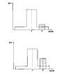
- FIG. 9 is a diagram illustrating a specific example of a signal power spectrum of a radio carrier signal.
- FIG. 10 is a diagram illustrating a specific example of a signal power spectrum of a radio carrier signal.
- FIG. 1 is a diagram illustrating a configuration of a wireless communication system according to an embodiment.
- the wireless communication system includes a base station device 100 and a terminal device 200.
- the base station device 100 and the terminal device 200 perform wireless communication with each other.
- a signal transmitted from the base station apparatus 100 to the terminal apparatus 200 is referred to as a “DL (DownLink: downlink radio channel) signal”
- UL (UpLink: Uplink radio channel) signal a signal transmitted from the terminal apparatus 200 to the base station apparatus 100
- Downlink is sometimes referred to as Forward link
- Uplink is sometimes referred to as Reverse link.
- the base station apparatus 100 includes a radio unit 100a, a processor 100b, and a memory 100c.
- the radio unit 100a performs a predetermined radio transmission process on the DL signal output from the processor 100b and transmits the DL signal via an antenna. Further, the radio unit 100a receives the UL signal via the antenna, and performs a predetermined radio reception process on the UL signal.
- the processor 100b includes, for example, a CPU (Central Processing Unit), an FPGA (Field Programmable Gate Array), a DSP (Digital Signal Processor), and the like, and performs overall control of the base station apparatus 100 as a whole. That is, the processor 100b encodes and modulates transmission data to generate a DL signal, and outputs the DL signal to the radio unit 100a. Further, the processor 100b demodulates and decodes the UL signal input from the wireless unit 100a to obtain received data.
- the memory 100c includes, for example, a RAM (Random Access Memory) or a ROM (Read Only Memory), and stores various types of information when processing is executed by the processor 100b. The configuration of base station apparatus 100 will be described in detail later.
- the terminal device 200 includes a wireless unit 200a, a processor 200b, and a memory 200c. In FIG. 1, one terminal device 200 is illustrated, but a plurality of terminal devices may perform wireless communication with the base station device 100.
- the radio unit 200a receives a DL signal via an antenna and performs a predetermined radio reception process on the DL signal. In addition, the radio unit 200a performs a predetermined radio transmission process on the UL signal output from the processor 200b and transmits the UL signal via an antenna.
- the processor 200b includes, for example, a CPU, FPGA, DSP, or the like, and performs overall control of the entire terminal device 200. That is, the processor 200b demodulates and decodes the DL signal input from the radio unit 200a to obtain received data. Further, the processor 200b encodes and modulates transmission data to generate a UL signal, and outputs the UL signal to the radio unit 200a.
- the memory 200c includes, for example, a RAM or a ROM, and stores various types of information when processing is executed by the processor 200b. The configuration of the terminal device 200 will be described in detail later.
- FIG. 2 is a block diagram showing a configuration of base station apparatus 100 according to one embodiment.
- the base station apparatus 100 shown in FIG. 2 includes signal generation units 101-1 and 101-2, gain adjustment units 102-1 and 102-2, filter units 103-1 and 103-2, and D / A (Digital / Analog).
- a conversion unit 104 and a wireless transmission unit 105 are included.
- the base station apparatus 100 includes a radio reception unit 106, an A / D (Analog / Digital) conversion unit 107, an interference state evaluation unit 108, a gain control unit 109, filter units 110-1 and 110-2, and a decoding unit 111-. 1, 111-2.
- the D / A conversion unit 104, the wireless transmission unit 105, the wireless reception unit 106, and the A / D conversion unit 107 correspond to the wireless unit 100a illustrated in FIG. 1, and the other processing units are the processor 100b illustrated in FIG.
- the other processing units are the processor 100b illustrated in FIG.
- the signal generators 101-1 and 101-2 generate signals to be transmitted in subbands having different frequencies. Specifically, the signal generation unit 101-1 generates, for example, a signal transmitted in the subband # 1 having the center frequency f1 included in the frequency band of the radio carrier signal. Further, the signal generation unit 101-2 generates a signal transmitted in the subband # 2 having the center frequency f2 included in the frequency band of the same radio carrier signal.
- Each subband is composed of a plurality of subcarriers, and the subcarrier frequency interval is the same within the subband, but the subcarrier frequency interval may be different between the subbands.
- Each subband is used to transmit data of different applications, for example, and includes data addressed to different terminal devices.
- the radio carrier signal here is an OFDM signal transmitted by one radio carrier, for example, and is composed of a plurality of subcarrier signals.
- the frequency band of the radio carrier signal is, for example, a frequency region occupied by one OFDM signal, and may include guard band portions that are normally set at both ends of the OFDM signal.
- the radio carrier signal may be a DFT (Discrete Fourier Transform) -S (Spread) -OFDM signal used in an uplink radio channel of LTE.
- subbands # 1 and # 2 may be composed of a plurality of subcarriers, for example, when the radio carrier signal is an OFDM signal. Corresponds to "frequency domain".
- the signal generators 101-1 and 101-2 are configured to increase the DL adjustment information indicating that the DL signal transmission power is decreased and the UL signal transmission power according to the instruction from the gain control unit 109. UL adjustment information for instructing the apparatus 200 is generated.
- the gain adjustment units 102-1 and 102-2 adjust the gains of the signals generated by the signal generation units 101-1 and 101-2, respectively, in accordance with instructions from the gain control unit 109.
- gain adjustment section 102-1 is a symbol included in the signal of subband # 1 generated by signal generation section 101-1, and is transmitted simultaneously with reception in adjacent subband # 2. Decrease symbol gain.
- gain adjustment section 102-2 is a symbol gain included in the signal of subband # 2 generated by signal generation section 101-2, and transmitted at the same time as reception in adjacent subband # 1. Reduce.
- the symbol When the signals generated by the signal generators 101-1 and 101-2 are OFDM signals, the symbol has an OFDM symbol having a length corresponding to the reciprocal of the frequency bandwidth of the subcarriers constituting the OFDM signal. It is. Normally, a guard interval (also referred to as a cyclic prefix) is included in one OFDM symbol.
- Gain adjusting sections 102-1 and 102-2 reduce the gain of the symbol when the entire symbol is transmitted overlapping with reception in adjacent subbands. In other words, gain adjusting sections 102-1 and 102-2 do not decrease the gain in principle for symbols that are transmitted without overlapping any reception in adjacent subbands.
- Filter sections 103-1 and 103-2 perform filtering for transmitting subbands having different frequencies to the subband signals whose gains are adjusted, and signals whose frequency components outside the subbands are suppressed. Is output. Specifically, for example, the filter unit 103-1 transmits the subband # 1 frequency component and suppresses other frequency components, thereby outputting the subband # 1 signal. Further, the filter unit 103-2 outputs a signal of the subband # 2 by transmitting, for example, the frequency component of the subband # 2 and suppressing other frequency components.
- the D / A converter 104 performs D / A conversion on the DL signal obtained by synthesizing the signals of each subband, and outputs the obtained analog DL signal.
- the radio transmission unit 105 performs radio transmission processing such as frequency conversion to a radio frequency band and amplification on the DL signal, and transmits the DL signal via an antenna. Note that in the course of wireless transmission processing in the wireless transmission unit 105, nonlinear distortion occurs from the signals of each subband included in the DL signal, and at least a part of the nonlinear distortion wraps around to the circuit on the reception side.
- the radio reception unit 106 receives the UL signal via the antenna, and performs radio reception processing such as frequency conversion to the baseband frequency band and amplification on the UL signal.
- the A / D converter 107 A / D converts the UL signal and outputs the obtained digital UL signal.
- the interference state evaluation unit 108 uses the digital DL signal obtained by combining the signals of the subbands and the digital UL signal output from the A / D conversion unit 107 to give the DL signal to the UL signal. Evaluate the state of interference. Specifically, the interference state evaluation unit 108 calculates, for example, the correlation between the output signal from the A / D conversion unit 107 and the DL signal, and how much nonlinear distortion generated from the DL signal is added to the UL signal. Detect whether or not Then, the interference state evaluation unit 108 notifies the gain control unit 109 of the interference state of the DL signal with the UL signal.
- the gain control unit 109 acquires a bitmap indicating the transmission timing of the DL signal and the UL signal in each subband, and determines an adjustment symbol that is a target for adjusting the gain among symbols constituting the DL signal and the UL signal. . That is, the gain control unit 109 refers to the bitmap and transmits the DL signal symbols transmitted in one subband at the same timing as the UL signal symbols transmitted in the other subbands. The determined symbol is determined as an adjustment symbol for the downlink radio channel. In addition, the gain control unit 109 refers to the bitmap and transmits the UL signal symbols transmitted in one subband at the same timing as the symbols of the DL signal transmitted in the other subbands. The determined symbol is determined as an adjustment symbol for the uplink radio channel. That is, gain control section 109 determines, in base station apparatus 100, a symbol that is received or transmitted simultaneously with transmission or reception of adjacent subband symbols as an adjustment symbol.
- the gain control unit 109 determines the gain of the adjustment symbol based on the interference state notified from the interference state evaluation unit 108. Specifically, the gain control unit 109 determines to set a gain lower than a normal gain for the downlink radio channel adjustment symbol in order to suppress interference with the UL signal. Also, the gain control unit 109 determines to set a gain higher than a normal gain for the adjustment symbol of the uplink radio channel in order to reduce the influence of interference due to the DL signal. At this time, the gain control unit 109 determines the amount of decrease or increase in gain so that the interference detected by the interference state evaluation unit 108 is reduced.
- the gain control unit 109 determines the gain of the adjustment symbol for the downlink radio channel
- the gain control unit 109 sends the determined gain to the gain adjustment unit 102-1, 102 at the timing when the adjustment symbol is output from the signal generation unit 101-1, 101-2. Set to -2.
- gain adjustment sections 102-1 and 102-2 lower the gain of the adjustment symbol of the downlink radio channel from the gain of other symbols.
- the gain control unit 109 also causes the signal generation units 101-1 and 101-2 to generate DL adjustment information indicating the position of the adjustment symbol of the downlink radio channel and the gain to be reduced, and transmits the DL adjustment information to the terminal device 200. Thereby, the gain of the adjustment symbol of the downlink radio channel can be reduced, and the terminal device 200 can be notified that the gain of the adjustment symbol is reduced.
- the gain control unit 109 determines the gain of the adjustment symbol of the uplink radio channel
- the gain control unit 109 transmits UL adjustment information indicating the position of the adjustment symbol of the uplink radio channel and the gain to be increased to the signal generation units 101-1 and 101-2. Generated and transmitted to the terminal device 200. Thereby, it is possible to instruct the terminal apparatus 200 to increase the gain of the adjustment symbol of the uplink radio channel.
- the filter units 110-1 and 110-2 execute filtering that transmits subbands of different frequencies on the UL signal output from the A / D conversion unit 107, and outputs a signal for each subband. Specifically, the filter unit 110-1 outputs a signal of the subband # 1 by, for example, transmitting a frequency component of the subband # 1 and suppressing other frequency components. In addition, the filter unit 110-2 outputs a signal of the subband # 2 by transmitting the frequency component of the subband # 2 and suppressing other frequency components, for example.
- the decoding units 111-1 and 111-2 demodulate and decode signals in different subbands, and acquire data transmitted in each subband.
- FIG. 3 is a block diagram illustrating a configuration of the terminal device 200 according to an embodiment.
- 3 includes a radio reception unit 201, an A / D conversion unit 202, a pilot signal extraction unit 203, a radio characteristic estimation unit 204, a demodulation unit 205, a decoding unit 206, and an adjustment symbol determination unit 207.
- the terminal device 200 includes a signal generation unit 208, a gain adjustment unit 209, a D / A conversion unit 210, and a wireless transmission unit 211.
- the wireless reception unit 201, the A / D conversion unit 202, the D / A conversion unit 210, and the wireless transmission unit 211 correspond to the wireless unit 200a illustrated in FIG. 1, and the other processing units are the processor 200b illustrated in FIG. Corresponding to
- terminal apparatus 200 performs radio communication with base station apparatus 100 using subband # 2 having a subcarrier frequency interval and a short symbol length among subbands # 1 and # 2. . Since the symbol length of subband # 2 is shorter than the symbol length of subband # 1, adjustment symbols that are gain adjustment targets are transmitted and received in subband # 2.
- the radio reception unit 201 receives a DL signal via an antenna and performs radio reception processing such as frequency conversion to the baseband frequency band and amplification on the DL signal.
- the DL signal subband # 2 includes DL adjustment information, UL adjustment information, and the like in addition to the data addressed to the terminal apparatus 200.
- the A / D conversion unit 202 A / D converts the DL signal and outputs the obtained digital DL signal.
- the pilot signal extraction unit 203 extracts a known pilot signal from the DL signal. That is, since a known pilot signal is inserted in the DL signal in order to estimate radio characteristics, the pilot signal extraction unit 203 extracts the pilot signal inserted in the DL signal.
- Radio characteristic estimation section 204 estimates the radio characteristics between base station apparatus 100 and terminal apparatus 200 using the pilot signal. At this time, if the pilot signal is extracted from the adjustment symbol transmitted with a reduced gain, radio characteristic estimating section 204 corrects the gain decrease in base station apparatus 100 and estimates the radio characteristic. . That is, the radio characteristic estimation unit 204 grasps the position of the adjustment symbol of the downlink radio channel and the reduced gain based on the DL adjustment information, and estimates the radio characteristic by compensating for the pilot signal quality reduction due to the gain reduction. Radio characteristic estimating section 204 notifies demodulated section 205 and signal generating section 208 of the estimated radio characteristics.
- the demodulator 205 demodulates the DL signal using the radio characteristics estimated by the radio characteristic estimator 204.
- the decoding unit 206 decodes the subband # 2 signal included in the DL signal, and acquires data addressed to the terminal device 200. Also, decoding section 206 acquires DL adjustment information and UL adjustment information from the signal of subband # 2, and outputs the DL adjustment information and UL adjustment information to adjustment symbol determination section 207.
- the adjustment symbol determination unit 207 acquires the position of the adjustment symbol of the downlink radio channel and the reduced gain from the DL adjustment information, and notifies the radio characteristic estimation unit 204 of information related thereto. Also, the adjustment symbol determination unit 207 acquires the position of the adjustment symbol of the uplink radio channel and the gain to be increased from the UL adjustment information, and notifies the gain adjustment unit 209 of information related thereto.
- the signal generation unit 208 generates a signal to be transmitted in subband # 2 from data addressed to the base station apparatus 100. Further, the signal generation unit 208 generates a signal of subband # 2 including radio characteristic information for reporting the radio characteristic estimated by the radio characteristic estimation unit 204 to the base station apparatus 100.
- the gain adjustment unit 209 increases the gain of the adjustment symbol of the uplink radio channel in accordance with the notification from the adjustment symbol determination unit 207. That is, gain adjustment section 209 increases the gain of the adjustment symbol designated by the UL adjustment information from base station apparatus 100 among the symbols constituting the signal of subband # 2. Thereby, the transmission power of the adjustment symbol is increased, and in base station apparatus 100, the reception power of the adjustment symbol that is received overlapping with the transmission of the DL signal is increased.
- the D / A conversion unit 210 D / A converts the UL signal including the subband # 2 signal and outputs the obtained analog UL signal.
- the radio transmission unit 211 performs radio transmission processing such as frequency conversion to a radio frequency band and amplification on the UL signal, and transmits the UL signal via an antenna.
- base station apparatus 100 configured as described above will be described separately for DL signal transmission and UL signal reception.
- the frequency interval between subcarriers in subband # 2 of center frequency f2 is larger than the frequency interval between subcarriers of subband # 1 of center frequency f1. Therefore, the symbol length of subband # 2 is shorter than the symbol length of subband # 1.
- base station apparatus 100 shall perform radio
- FIG. 4 is a flowchart showing processing at the time of DL signal transmission by the base station apparatus 100.
- Base station apparatus 100 transmits a DL signal to terminal apparatus 200 using subband # 2, and at the same time, performs radio communication with another terminal apparatus using subband # 1.
- the gain control unit 109 obtains a bitmap indicating the symbol position in each subband (step S101).
- the bitmap shows allocation of the downlink radio channel and the uplink radio channel to each symbol for each subband.
- a bitmap having a shorter symbol length in subband # 2 is acquired.
- Such a bitmap is defined in advance in a wireless communication system that employs TDD in which assignment of symbols to downlink and uplink radio channels is fixed.
- the gain control unit 109 acquires the position of the adjustment symbol for the downlink radio channel based on the bitmap (step S102). Specifically, among the symbols of the downlink radio channel of subband # 2 having a short symbol length, symbols transmitted overlapping with the symbols of the uplink radio channel of subband # 1 are the adjustment symbols of the downlink radio channel. To be judged. Since the downlink radio channel adjustment symbol is transmitted at the same time as the uplink radio channel symbol of subband # 1 is received in the base station apparatus 100, it interferes with the received uplink radio channel symbol. It is thought to give.
- Step S103 When the position of the adjustment symbol for the downlink radio channel is acquired, DL adjustment information indicating the position of the adjustment symbol for the downlink radio channel and the gain to be reduced is generated by the signal generation unit 101-2 in accordance with an instruction from the gain control unit 109.
- the symbol of subband # 2 is an adjustment symbol
- DL adjustment information is generated by signal generation section 101-2 that generates a signal of subband # 2. Therefore, when the subband # 1 symbol is an adjustment symbol, the DL adjustment information may be generated by the signal generation unit 101-1 that generates the subband # 1 signal.
- the generated DL adjustment information is transmitted from the gain adjustment unit 102-2 to the wireless transmission unit 105 to the terminal device 200 via the antenna (step S104).
- DL signals addressed to a plurality of terminal devices including the terminal device 200 are generated by the signal generation units 101-1 and 101-2 (step S105). That is, the signal generation unit 101-2 generates a subband # 2 signal from the data addressed to the terminal device 200, and the signal generation unit 101-1 generates the subband # 1 signal from the data addressed to another terminal device. A signal is generated. Note that since TDD is employed in each subband, signals of all subbands do not necessarily have to be generated simultaneously. That is, it is only necessary that the signal generation units 101-1 and 101-2 generate a signal to be transmitted at a timing when each subband is allocated to the downlink radio channel.
- the generated subband signals are output to gain adjustment sections 102-1 and 102-2, and it is determined whether or not each symbol is a downlink radio channel adjustment symbol (step S106). For the adjustment symbol (Yes at Step S106), the gain adjustment units 102-1 and 102-2 reduce the gain as compared with the normal symbol (Step S107). At this time, the position of the adjustment symbol and the amount of gain reduction are instructed from the gain control unit 109 to the gain adjustment units 102-1 and 102-2.
- the signal of each subband whose gain is adjusted for each symbol is subjected to filtering for suppressing frequency components outside the respective subbands by the filter units 103-1 and 103-2 (step S108).
- a signal in which frequency components other than subband # 1 are suppressed is output from filter unit 103-1
- a signal in which frequency components other than subband # 2 are suppressed is output from filter unit 103-2. Is output.
- step S109 D / A conversion of the DL signal is performed by the D / A conversion unit 104, and the DL signal is transmitted after the wireless transmission unit 105 performs wireless transmission processing (step S109).
- the transmission power of the part corresponding to the adjustment symbol is smaller than that of the other part.
- the power of the adjustment symbol of the downlink radio channel of subband # 2 which is transmitted at the same time that base station apparatus 100 receives the symbol of the uplink radio channel in subband # 1, is small. For this reason, interference from subband # 2 can be reduced, and degradation of reception characteristics of uplink radio channel symbols received in subband # 1 can be suppressed.
- the DL signal obtained by combining the signals of the subbands is also input to the interference state evaluation unit 108, and for example, the DL signal is calculated by calculating the correlation with the output signal from the A / D conversion unit 107.
- the state of interference given to the UL signal is evaluated (step S110). That is, for example, when the correlation value between the output signal from the A / D conversion unit 107 and the DL signal is greater than or equal to a predetermined value, the DL signal power that wraps around to the receiving side is high and the interference on the UL signal is large. Conceivable.
- the interference state evaluated in this way is notified to the gain control unit 109.
- the gain control unit 109 determines a gain reduction amount for reducing the interference, and updates the gain reduction amount for the downlink radio channel adjustment symbol (step S111). That is, for example, when the interference exceeds a predetermined reference, the gain reduction amount of the adjustment symbol of the downlink radio channel is further increased. On the other hand, for example, when the interference is less than the predetermined reference, the gain reduction amount of the adjustment symbol of the downlink radio channel Make it smaller. Thereby, the gain reduction amount of the adjustment symbol of the downlink radio channel is adjusted so as to optimize the interference state.
- FIG. 5 is a flowchart showing processing when the base station apparatus 100 receives a UL signal. Prior to receiving the UL signal, the base station device 100 permits the terminal device 200 to transmit the UL signal.
- the gain control unit 109 acquires a bitmap indicating the symbol position in each subband (step S201).
- a bitmap having a shorter symbol length in subband # 2 is acquired.
- the gain control unit 109 acquires the position of the adjustment symbol of the uplink radio line based on the bitmap (step S202). Specifically, among the uplink radio channel symbols of subband # 2 having a short symbol length, symbols transmitted in duplicate with the downlink radio channel symbols of subband # 1 are uplink radio channel adjustment symbols. To be judged. Such an uplink radio channel adjustment symbol is received at the base station apparatus 100 at the same time as the downlink radio channel symbol of subband # 1 is transmitted. It is thought to receive.
- UL adjustment information that indicates the position of the adjustment symbol of the uplink radio channel and the gain to be increased by the signal generation unit 101-2 according to the instruction from the gain control unit 109 is obtained. It is generated (step S203).
- the symbol of subband # 2 is an adjustment symbol
- UL adjustment information is generated by signal generation section 101-2 that generates a signal of subband # 2. Therefore, when the subband # 1 symbol is an adjustment symbol, the UL adjustment information may be generated by the signal generation unit 101-1 that generates the subband # 1 signal.
- the generated UL adjustment information is transmitted from the gain adjustment unit 102-2 to the wireless transmission unit 105 to the terminal device 200 via the antenna (step S204).
- the terminal apparatus 200 that receives the UL adjustment information transmits a UL signal by increasing the gain of the adjustment symbol of the uplink radio channel according to the UL adjustment information.
- the transmitted UL signal is received by the radio reception unit 106 of the base station apparatus 100 (step S205) and A / D converted by the A / D conversion unit 107.
- the UL signal is filtered by the filter units 110-1 and 110-2, and respective subband signals are obtained.
- the signals in each subband are demodulated and decoded by the decoding units 111-1 and 111-2, and data for each subband is acquired.
- the UL signal output from the A / D conversion unit 107 is also input to the interference state evaluation unit 108.
- the UL signal is received from the DL signal by calculating the correlation with the DL signal at the corresponding timing.
- the state of interference is evaluated (step S206). That is, for example, when the correlation value between the output signal from the A / D conversion unit 107 and the DL signal is equal to or greater than a predetermined value, the power of the DL signal that wraps around to the reception side is high, and the interference received by the UL signal is large. it is conceivable that.
- the interference state evaluated in this way is notified to the gain control unit 109.
- the gain increase unit 109 determines the gain increase amount for reducing the interference, and updates the gain increase amount for the uplink radio channel adjustment symbol (step S207). That is, for example, when the interference exceeds a predetermined reference, the gain increase amount of the adjustment symbol of the uplink radio channel is further increased, while, for example, when the interference is less than the predetermined reference, the gain increase amount of the adjustment symbol of the uplink radio channel Make it smaller. Thereby, the gain increase amount of the adjustment symbol of the uplink radio channel is adjusted so as to optimize the interference state.
- the operation of the terminal device 200 will be described separately for DL signal reception and UL signal transmission.
- the frequency interval between subcarriers in subband # 2 of center frequency f2 is larger than the frequency interval between subcarriers in subband # 1 of center frequency f1. Therefore, the symbol length of subband # 2 is shorter than the symbol length of subband # 1.
- the terminal device 200 shall perform radio
- FIG. 6 is a flowchart showing processing when the terminal device 200 receives a DL signal.
- Terminal apparatus 200 receives the signal of subband # 2, and reports the radio characteristics of subband # 2 to base station apparatus 100.
- the base station apparatus 100 transmits a DL signal including DL adjustment information.
- This DL signal is received by the radio reception unit 201 of the terminal device 200 (step S301), and is decoded by the decoding unit 206, whereby DL adjustment information is obtained.
- the DL adjustment information is output to the adjustment symbol determination unit 207, and the adjustment symbol determination unit 207 acquires the position of the adjustment symbol on the downlink radio channel and the gain that decreases. Then, information on the position of the adjustment symbol on the downlink radio channel and the gain that decreases is notified to radio characteristic estimation section 204.
- the base station apparatus 100 also transmits a DL signal including data addressed to the terminal apparatus 200.
- This DL signal is received by the wireless reception unit 201 of the terminal device 200 (step S302), and A / D converted by the A / D conversion unit 202.
- pilot signal extraction section 203 extracts a subband # 2 pilot signal (step S303).
- the extracted pilot signal is output to radio characteristic estimation section 204, and the radio characteristic of subband # 2 is estimated by using the pilot signal (step S304).
- step S305 it is determined whether or not the pilot signal is extracted from the adjustment symbol. If the pilot signal is extracted from the adjustment symbol (Yes in step S305), the radio characteristic with the gain reduction corrected is estimated (step S306). That is, since the reception quality of the pilot signal is also reduced due to the gain reduction of the adjustment symbol, the radio characteristics of subband # 2 are estimated by compensating for the quality reduction due to the gain reduction.
- the estimated radio characteristics of subband # 2 are notified to the demodulator 205 and the signal generator 208, and the demodulator 205 demodulates the DL signal using the radio characteristics (step S307). That is, the subband # 2 signal included in the DL signal is demodulated, and the decoding unit 206 decodes the subband # 2 signal, whereby data destined for the terminal device 200 is acquired.
- a signal including radio characteristic information for reporting the radio characteristics of subband # 2 is generated and transmitted to base station apparatus 100 using subband # 2. (Step S308).
- the reported radio characteristics are used, for example, to determine MCS (Modulation and Coding Scheme) when generating a signal addressed to the terminal device 200.
- FIG. 7 is a flowchart showing processing when the terminal device 200 transmits a UL signal.
- the terminal device 200 transmits the signal of subband # 2 when the transmission permission from the base station device 100 is obtained.
- a DL signal including UL adjustment information is transmitted.
- This DL signal is received by the radio reception unit 201 of the terminal device 200 (step S401), and is decoded by the decoding unit 206, thereby obtaining UL adjustment information.
- the UL adjustment information is output to the adjustment symbol determination unit 207, and the adjustment symbol determination unit 207 acquires the position of the adjustment symbol on the uplink radio channel and the gain to be increased. Then, information on the position of the adjustment symbol on the uplink radio channel and the gain to be increased is notified to gain adjustment section 209.
- step S402 when transmitting a UL signal from the terminal device 200, transmission permission from the base station device 100 is waited (step S402). Note that the UL adjustment information described above may be received together with the transmission permission of the UL signal.
- the signal generation unit 208 When transmission of the UL signal is permitted (Yes at Step S402), the signal generation unit 208 generates a signal of subband # 2 from the data addressed to the base station apparatus 100 (Step S403).
- the generated signal of subband # 2 is output to gain adjustment section 209, and it is determined for each symbol whether or not it is an adjustment symbol for the uplink radio channel (step S404).
- the gain adjustment unit 209 increases the gain as compared with the normal symbol (Step S405).
- the adjustment symbol determination unit 207 notifies the gain adjustment unit 209 of the position of the adjustment symbol and the gain increase amount.
- the subband # 2 signal whose gain is adjusted for each symbol is D / A converted by the D / A conversion unit 104, subjected to radio transmission processing by the radio transmission unit 211, and transmitted (step S406). .
- this UL signal since the gain of the adjustment symbol is increased, the transmission power of the portion corresponding to the adjustment symbol is larger than that of the other portions. In other words, the power of the adjustment symbol of the uplink radio channel of subband # 2 received at the same time that base station apparatus 100 transmits the symbol of the downlink radio channel in subband # 1 is large. For this reason, the influence of the interference received from subband # 1 can be reduced, and the deterioration of the reception characteristics of the uplink radio channel symbol received in subband # 2 can be suppressed.
- FIG. 8 is a diagram illustrating a specific example of the symbol configuration of the carrier frequency band.
- the carrier frequency band includes a subband # 1 having a center frequency f1 and a subband # 2 having a center frequency f2, and TDD is employed in each subband. That is, in FIG. 8, “DL” indicates a downlink radio channel symbol, and “UL” indicates an uplink radio channel symbol.
- the symbol length of subband # 2 is shorter than the symbol length of subband # 1, and each symbol of subband # 2 entirely overlaps with one symbol of subband # 1.
- each symbol of subband # 1 does not entirely overlap with one symbol of subband # 2.
- the adjustment symbol to be gain adjusted is a symbol of subband # 2 having a short symbol length.
- symbol groups 301 to 303 of subband # 2 are adjustment symbols. That is, since symbol groups 301 and 303 are symbols of the uplink radio channel of subband # 2 transmitted at the timing at which the symbols of the downlink radio channel of subband # 1 are transmitted, they are adjustment symbols.
- Symbol group 302 is an adjustment symbol because it is a symbol of the downlink radio channel of subband # 2 transmitted at the timing at which the symbol of the uplink radio channel of subband # 1 is transmitted. In this way, a symbol transmitted on a line in a direction opposite to the line of the adjacent subband is an adjustment symbol.
- the base station apparatus 100 receives interference from symbols on the downlink radio channel of subband # 1. For this reason, when the terminal apparatus 200 is instructed by the UL adjustment information, the gains of the symbol groups 301 and 303 increase. As a result, the received power in the base station apparatus 100 of the symbol groups 301 and 303 increases, and the influence of interference received from the symbols on the downlink radio channel of subband # 1 can be reduced.
- the UL signal of subband # 2 is interfered by frequency components generated outside the band of the DL signal of subband # 1. Therefore, as shown in the lower part of FIG. 9, the influence of interference from subband # 1 can be relatively reduced by increasing the power of the UL signal of subband # 2.
- the base station apparatus 100 interferes with the symbol of the uplink radio channel of subband # 1. Therefore, the gain of the symbol group 302 is reduced by adjusting the gain of the gain adjusting unit 102-2 by the gain control unit 109. As a result, the power in base station apparatus 100 of symbol group 302 is reduced, and interference given to symbols on the uplink radio channel of subband # 1 can be reduced.
- the subband # 2 DL signal interferes with the subband # 1 UL signal due to the frequency component generated outside the band. Therefore, as shown in the lower part of FIG. 10, by reducing the power of the DL signal of subband # 2, it is possible to reduce interference given to subband # 1.
- the power of the signal input to the power amplifier included in the wireless transmission unit 105 is reduced, so that nonlinear distortion generated in the power amplifier is reduced.
- the frequency component generated outside the band of subband # 2 is reduced, and the interference given to subband # 1 is reduced.
- the gain of the symbol of one line is reduced. Or increase.
- the base station apparatus it is possible to reduce interference caused by the subband assigned to the downlink radio channel to the subband assigned to the uplink radio channel, and to suppress degradation of reception characteristics of the signal of the uplink radio channel. be able to.
- the DL adjustment information is transmitted in the same subband as the adjustment symbol, but the DL adjustment information may not be transmitted in the same subband as the adjustment symbol. That is, the DL adjustment information may be broadcast using a broadcast channel that can be received by all terminal apparatuses communicating with the base station apparatus 100.
Landscapes
- Engineering & Computer Science (AREA)
- Computer Networks & Wireless Communication (AREA)
- Signal Processing (AREA)
- Mobile Radio Communication Systems (AREA)
Abstract
Un appareil de station de base (100) comprend : une unité de génération (101-1, 101-2) qui génère un signal à transmettre dans une première région de fréquence comprise dans une bande de fréquence d'un signal de porteuse sans fil ; une unité de réglage (102-1, 102-2) qui règle, par symbole, le gain du signal généré par l'unité de génération (101-1, 101-2) ; une unité de transmission (105) qui transmet un signal obtenu par un réglage de gain par l'unité de réglage (102-1, 1022) ; une unité de réception (106) qui reçoit un signal dans une seconde région de fréquence comprise dans la bande de fréquence du signal de porteuse sans fil ; et une unité de commande (109) qui, sur la base d'un agencement de symboles pour un canal sans fil en aval et d'un canal sans fil en amont dans la première région de fréquence et dans la deuxième région de fréquence, détermine un symbole de réglage devant être soumis à un réglage de gain, et diminue ou augmente le gain du symbole de réglage déterminé par rapport à d'autres symboles.
Priority Applications (1)
| Application Number | Priority Date | Filing Date | Title |
|---|---|---|---|
| PCT/JP2016/060795 WO2017168712A1 (fr) | 2016-03-31 | 2016-03-31 | Appareil de station de base, appareil terminal, système de communication sans fil et procédé de communication sans fil |
Applications Claiming Priority (1)
| Application Number | Priority Date | Filing Date | Title |
|---|---|---|---|
| PCT/JP2016/060795 WO2017168712A1 (fr) | 2016-03-31 | 2016-03-31 | Appareil de station de base, appareil terminal, système de communication sans fil et procédé de communication sans fil |
Publications (1)
| Publication Number | Publication Date |
|---|---|
| WO2017168712A1 true WO2017168712A1 (fr) | 2017-10-05 |
Family
ID=59962757
Family Applications (1)
| Application Number | Title | Priority Date | Filing Date |
|---|---|---|---|
| PCT/JP2016/060795 WO2017168712A1 (fr) | 2016-03-31 | 2016-03-31 | Appareil de station de base, appareil terminal, système de communication sans fil et procédé de communication sans fil |
Country Status (1)
| Country | Link |
|---|---|
| WO (1) | WO2017168712A1 (fr) |
Citations (4)
| Publication number | Priority date | Publication date | Assignee | Title |
|---|---|---|---|---|
| WO2008126623A1 (fr) * | 2007-03-20 | 2008-10-23 | Ntt Docomo, Inc. | Dispositif d'utilisateur, dispositif de station de base, et procédé dans un système de communication mobile |
| WO2014085710A1 (fr) * | 2012-11-29 | 2014-06-05 | Interdigital Patent Holdings, Inc. | Réduction de la fuite spectrale dans un système ofdm |
| US20150200764A1 (en) * | 2012-09-29 | 2015-07-16 | Huawei Technologies Co., Ltd. | Signal processing method, apparatus, and system |
| JP2016508304A (ja) * | 2012-12-11 | 2016-03-17 | エルジー エレクトロニクス インコーポレイティド | 無線通信システムで信号を送受信する方法及びこのための装置 |
-
2016
- 2016-03-31 WO PCT/JP2016/060795 patent/WO2017168712A1/fr active Application Filing
Patent Citations (4)
| Publication number | Priority date | Publication date | Assignee | Title |
|---|---|---|---|---|
| WO2008126623A1 (fr) * | 2007-03-20 | 2008-10-23 | Ntt Docomo, Inc. | Dispositif d'utilisateur, dispositif de station de base, et procédé dans un système de communication mobile |
| US20150200764A1 (en) * | 2012-09-29 | 2015-07-16 | Huawei Technologies Co., Ltd. | Signal processing method, apparatus, and system |
| WO2014085710A1 (fr) * | 2012-11-29 | 2014-06-05 | Interdigital Patent Holdings, Inc. | Réduction de la fuite spectrale dans un système ofdm |
| JP2016508304A (ja) * | 2012-12-11 | 2016-03-17 | エルジー エレクトロニクス インコーポレイティド | 無線通信システムで信号を送受信する方法及びこのための装置 |
Similar Documents
| Publication | Publication Date | Title |
|---|---|---|
| EP3606237B1 (fr) | Procédé et appareil de réglage et de transmission d'unité de ressource | |
| US10524252B2 (en) | Mobile terminal apparatus, base station apparatus, and radio communication method for cell discovery timing | |
| US8798680B2 (en) | Wireless cellular network using adaptive beamforming with different coverage for control and data channels | |
| US20110134901A1 (en) | Radio communication device and radio communication method | |
| KR20130022523A (ko) | 다수의 직교 주파수 분할 다중 파라미터 셋을 지원하는 무선통신 시스템에서 통신 방법 및 장치 | |
| US20180062823A1 (en) | Base station and method using a base station | |
| WO2016114824A1 (fr) | Appareil et procédé pour fournir un intervalle de protection flexible pour une transmission de porteuse unique de bloc | |
| EP3565165A1 (fr) | Dispositif de communication et procédé d'envoi de signal de référence | |
| US10341154B2 (en) | Method for multiple access transmission in a wireless communication system, and a transmitter apparatus and a base station therefor | |
| US8619885B2 (en) | Radio communication system | |
| US20210135919A1 (en) | Method and device for performing communication by using orthogonal or non-orthogonal code multiple access scheme in wireless communication system | |
| EP2543152A2 (fr) | Estimation de la qualité d'un signal dans des systèmes de communication sans fil | |
| US8675761B2 (en) | Allocating antennas for cyclic delay diversity transmission | |
| US8867459B2 (en) | Mobile subscriber information transmission over multiple uplink frames | |
| WO2017168712A1 (fr) | Appareil de station de base, appareil terminal, système de communication sans fil et procédé de communication sans fil | |
| US11456762B2 (en) | Control device and radio communication device | |
| US11528732B2 (en) | Method and network node for handling transmission of LTE or NR signals and NB-IoT signals to wireless communication devices | |
| JP5571116B2 (ja) | 無線通信装置 | |
| JP6362156B2 (ja) | 無線通信システム、無線通信装置および無線通信方法 | |
| US20180013470A1 (en) | Transmission control device and transmission control method | |
| Takakusaki et al. | Implementation of experimental equipment with Wideband Non-Contiguous OFDM | |
| US20240163847A1 (en) | Communication device, communication method, communication system, and program | |
| US9236975B2 (en) | Mobile subscriber information transmission over multiple uplink frames | |
| WO2018020727A1 (fr) | Dispositif de communication, procédé et programme de commande | |
| CN118266174A (zh) | 用于无线通信系统中的智能中继器的控制信息信令的方法和装置 |
Legal Events
| Date | Code | Title | Description |
|---|---|---|---|
| NENP | Non-entry into the national phase |
Ref country code: DE |
|
| 121 | Ep: the epo has been informed by wipo that ep was designated in this application |
Ref document number: 16896929 Country of ref document: EP Kind code of ref document: A1 |
|
| 122 | Ep: pct application non-entry in european phase |
Ref document number: 16896929 Country of ref document: EP Kind code of ref document: A1 |
|
| NENP | Non-entry into the national phase |
Ref country code: JP |