WO2017164618A2 - 블루투스 기술을 이용하여 디바이스를 제어하기 위한 방법 및 장치 - Google Patents
블루투스 기술을 이용하여 디바이스를 제어하기 위한 방법 및 장치 Download PDFInfo
- Publication number
- WO2017164618A2 WO2017164618A2 PCT/KR2017/003022 KR2017003022W WO2017164618A2 WO 2017164618 A2 WO2017164618 A2 WO 2017164618A2 KR 2017003022 W KR2017003022 W KR 2017003022W WO 2017164618 A2 WO2017164618 A2 WO 2017164618A2
- Authority
- WO
- WIPO (PCT)
- Prior art keywords
- control
- information
- request message
- role
- procedure
- Prior art date
Links
- 238000000034 method Methods 0.000 title claims abstract description 257
- 238000005516 engineering process Methods 0.000 title description 25
- 230000004044 response Effects 0.000 claims abstract description 71
- 238000004891 communication Methods 0.000 claims abstract description 43
- 230000009471 action Effects 0.000 claims description 11
- 108091006146 Channels Proteins 0.000 description 48
- 230000002093 peripheral effect Effects 0.000 description 38
- 239000003999 initiator Substances 0.000 description 36
- 238000012790 confirmation Methods 0.000 description 28
- 230000006870 function Effects 0.000 description 24
- 230000006399 behavior Effects 0.000 description 16
- 230000015654 memory Effects 0.000 description 16
- 230000008569 process Effects 0.000 description 16
- 230000000977 initiatory effect Effects 0.000 description 14
- 238000010586 diagram Methods 0.000 description 12
- 238000001914 filtration Methods 0.000 description 8
- 230000003993 interaction Effects 0.000 description 8
- 230000005540 biological transmission Effects 0.000 description 7
- 230000006978 adaptation Effects 0.000 description 4
- 238000012545 processing Methods 0.000 description 4
- 230000000694 effects Effects 0.000 description 3
- 238000012986 modification Methods 0.000 description 3
- 230000004048 modification Effects 0.000 description 3
- 238000004458 analytical method Methods 0.000 description 2
- 230000002457 bidirectional effect Effects 0.000 description 2
- 238000010276 construction Methods 0.000 description 2
- 238000013461 design Methods 0.000 description 2
- 238000007726 management method Methods 0.000 description 2
- 238000012806 monitoring device Methods 0.000 description 2
- 230000003068 static effect Effects 0.000 description 2
- 238000003860 storage Methods 0.000 description 2
- 230000008901 benefit Effects 0.000 description 1
- 230000008859 change Effects 0.000 description 1
- 239000004020 conductor Substances 0.000 description 1
- 238000007796 conventional method Methods 0.000 description 1
- 230000008878 coupling Effects 0.000 description 1
- 238000010168 coupling process Methods 0.000 description 1
- 238000005859 coupling reaction Methods 0.000 description 1
- 238000013500 data storage Methods 0.000 description 1
- 238000009826 distribution Methods 0.000 description 1
- 238000004519 manufacturing process Methods 0.000 description 1
- 230000007246 mechanism Effects 0.000 description 1
- 230000006855 networking Effects 0.000 description 1
- 230000003287 optical effect Effects 0.000 description 1
- 230000001151 other effect Effects 0.000 description 1
- 230000000737 periodic effect Effects 0.000 description 1
- 230000011218 segmentation Effects 0.000 description 1
- 230000011664 signaling Effects 0.000 description 1
- 230000001360 synchronised effect Effects 0.000 description 1
- 230000001960 triggered effect Effects 0.000 description 1
Images


Classifications
-
- H—ELECTRICITY
- H04—ELECTRIC COMMUNICATION TECHNIQUE
- H04Q—SELECTING
- H04Q9/00—Arrangements in telecontrol or telemetry systems for selectively calling a substation from a main station, in which substation desired apparatus is selected for applying a control signal thereto or for obtaining measured values therefrom
- H04Q9/04—Arrangements for synchronous operation
-
- H—ELECTRICITY
- H04—ELECTRIC COMMUNICATION TECHNIQUE
- H04W—WIRELESS COMMUNICATION NETWORKS
- H04W76/00—Connection management
- H04W76/10—Connection setup
Definitions
- the present invention relates to a method and apparatus for forming a device-to-device connection using Bluetooth, which is a short-range technology in a wireless communication system, and more particularly, to a method and apparatus for forming a device-to-device connection using Bluetooth technology.
- Bluetooth is a short-range wireless technology standard that can transmit and receive data by wirelessly connecting various devices in a short distance.
- a user When performing wireless communication between two devices using Bluetooth communication, a user performs a procedure of searching for a Bluetooth device and requesting a connection. do.
- the device may mean an apparatus and an apparatus.
- the user may perform a connection after searching for the Bluetooth device according to the Bluetooth communication method to use using the Bluetooth device.
- the Bluetooth communication method includes a basic rate / enhanced data rate (BR / EDR) method and a low energy (LE) method, which is a low power method.
- the BR / EDR scheme may be referred to as Bluetooth Classic.
- the Bluetooth classic includes Bluetooth technology that has been adopted since Bluetooth 1.0 using Basic Rate and Bluetooth technology that has used Enhanced Data Rate supported since Bluetooth 2.0.
- Bluetooth Low Energy (hereinafter referred to as Bluetooth LE) technology has been applied since Bluetooth 4.0, and can consume hundreds of kilobytes (KB) of information stably with low power consumption.
- the Bluetooth low energy energy technology uses an attribute protocol to exchange information between devices. This Bluetooth LE method can reduce energy overhead by reducing the header overhead and simplifying the operation.
- Some Bluetooth devices do not have a display or a user interface.
- the complexity of connection / management / control / disconnection between various kinds of Bluetooth devices and similarly applied Bluetooth devices is increasing.
- Bluetooth can achieve a relatively high speed at a relatively low power, low cost, but the transmission distance is generally limited to a maximum of 100m, it is suitable for use in a limited space.
- An object of the present invention is to provide a method and apparatus for controlling connection / pairing between devices using Bluetooth technology.
- control point procedure in the easy pairing service, although the operations according to one role are closely related to each other, the control point procedure may be performed separately for each operation or procedure. Is required. Thus, there is a problem that unnecessary interaction between the client device and the server device is required to instruct the related operation.
- an object of the present invention is to propose a method of performing a control point procedure based on a GAP role to solve such a problem.
- an object of the present invention proposes a method for transmitting a configuration of a single command to the procedures that have been previously performed through a number of steps based on the role of the GAP.
- An aspect of the present invention provides a method for a control device to control a first device using Bluetooth communication, the method comprising: establishing a Bluetooth connection with the first device; Transmitting a read request message to the first device requesting characteristic information related to a controllable operation supported by the first device; Receiving a read response message from the first device that includes the characteristic information in response to the read request message, wherein the characteristic information includes an operation field indicating an operation supported by the first device; Transmitting a first write request message for requesting writing of a characteristic for instructing performance of a specific role to the first device based on the characteristic information, wherein the first write request message is associated with the specific role; Includes associated control information; And receiving a write response message from the first device in response to the first write request message, wherein the control information includes role information indicating the specific role and parameter information indicating an operation associated with the specific role. It may include.
- the operation field may include at least one of a connection type, role, mode or procedure supported by the first device.
- said parameter information can comprise a plurality of mode information and procedure information for said first device to perform operations requested from said control device with a peer device.
- forming a Bluetooth LE connection with a peer device of said first device And if the address of the peer device is a random address, obtaining an identity resolving key (IRK) of the peer device for resolving the random address from the peer device.
- the control information may further include a parameter indicating an identifier resolution key of the peer device.
- the address of the first device is a random address
- obtaining an identifier resolution key of the first device for resolving the random address from the first device And sending a second write request message to the peer device, the second write request message including the identifier resolution key of the first device.
- Another aspect of the present invention is a method in which a connection between a first device and a peer device is controlled by a control device using Bluetooth communication, wherein the method performed in the first device comprises: Establishing a Bluetooth connection; Receiving a read request message from the control device requesting characteristic information related to a controllable operation supported by the first device; Sending a read response message including the characteristic information in response to the read request message to the control device, the characteristic information including an operation field indicating an operation supported by the first device; Receiving a write request message requesting writing of a characteristic to instruct performance of a specific role from the control device based on the characteristic information, wherein the write request message includes control information related to the specific role; and; And transmitting a write response message to the control device in response to the write request message, wherein the control information may include role information indicating the specific role and parameter information indicating an operation related to the specific role. have.
- said parameter information may comprise a plurality of mode information and procedure information for said first device to perform operations requested from said control device with said peer device.
- the method may further include establishing a connection with a peer device based on the control information.
- the control information is an identity resolving key (IRK) of the peer device for resolving the random address from the peer device. It may further include.
- receiving an advertising message containing the random address from the peer device Resolving the random address using an identifier resolution key of the peer device; And establishing a connection with the peer device based on the analyzed random address and the control information.
- control device for controlling a first device using Bluetooth communication
- the control device comprising: a communication unit for wirelessly or wired communication with an external device; And a processor operatively connected to the communication unit, wherein the processor forms a Bluetooth connection with the first device and reads a request for characteristic information related to a controllable operation supported by the first device.
- a write response message may be received from the first device, and the control information may include role information indicating the specific role and parameter information indicating an operation related to the specific role.
- the operation field may include at least one of a connection type, role, mode or procedure supported by the first device.
- said parameter information can comprise a plurality of mode information and procedure information for said first device to perform operations requested from said control device with a peer device.
- the processor establishes a Bluetooth LE connection with a peer device of the first device, and if the address of the peer device is a random address, resolves the random address from the peer device.
- INK identity resolving key
- the processor when the address of the first device is a random address, obtains an identifier resolution key of the first device for resolving the random address from the first device, and sends the first device to the peer device.
- the second write request message that includes the identifier resolution key of the device may be sent.
- a bearer type subfield (1 byte) for indicating a connection type may be deleted from a control point characteristic.
- FIG. 1 is a schematic diagram illustrating an example of a wireless communication system using the Bluetooth low power energy technology proposed in the present specification.
- FIG. 2 shows an example of an internal block diagram of a device that can implement the methods proposed herein.
- FIG. 3 is a diagram illustrating an example of a Bluetooth communication architecture to which the methods proposed herein may be applied.
- FIG. 4 is a diagram illustrating an example of a structure of a GATT (Generic Attribute Profile) of Bluetooth low power energy.
- GATT Generic Attribute Profile
- FIG. 5 is a flowchart illustrating a method of forming a connection using Bluetooth Low Energy (LE) between devices.
- LE Bluetooth Low Energy
- FIG. 6 is a view briefly illustrating a method for controlling another device through a control device proposed in the present specification.
- FIGS. 7 and 8 are diagrams illustrating an example of a profile structure for providing a service for controlling a device proposed in the present specification.
- FIG. 9 is a diagram illustrating an operation of a control point characteristic as an embodiment to which the present invention may be applied.
- FIG. 10 is a flowchart illustrating a method of controlling a device-to-device connection using a control device according to an embodiment to which the present invention is applied.
- FIG. 11 is a flowchart illustrating a method of controlling an LE connection between devices using a control device according to an embodiment to which the present invention may be applied.
- FIG. 12 is a flowchart illustrating a method of controlling a device-to-device connection using a control device according to an embodiment to which the present invention is applied.
- FIG. 1 is a schematic diagram illustrating an example of a wireless communication system using the Bluetooth low power energy technology proposed in the present specification.
- the wireless communication system 100 includes at least one server device 120 and at least one client device 110.
- the server device and the client device perform Bluetooth communication using Bluetooth Low Energy (BLE) technology.
- BLE Bluetooth Low Energy
- BLE technology Compared to Bluetooth Basic Rate / Enhanced Data Rate (BR / EDR) technology, BLE technology has a relatively small duty cycle, enables low-cost production, and significantly reduces power consumption through low data rates. If you use a coin cell battery, it can operate for more than a year.
- BR / EDR Bluetooth Basic Rate / Enhanced Data Rate
- the BLE technology simplifies the connection procedure between devices, and the packet size is smaller than that of the Bluetooth BR / EDR technology.
- the number of RF channels is 40
- the data rate supports 1Mbps
- the topology is a scatternet structure
- latency is 3ms
- (6) output power is less than 10mW (10dBm)
- (7) is mainly used in applications such as mobile phones, watches, sports, healthcare, sensors, device control.
- the server device 120 may operate as a client device in relation to other devices, and the client device may operate as a server device in relation to other devices. That is, in the BLE communication system, any one device may operate as a server device or a client device, and if necessary, operate as a server device and a client device.
- the server device 120 may include a data service device, a slave device device, a slave, a server, a conductor, a host device, a gateway, and a sensing device. (Sensing Device), a monitoring device (monitoring device), the first device, the second device and the like.
- the client device 110 may be a master device, a master, a client, a member, a sensor device, a sink device, a collector, a third device, a fourth device, or the like. Can be expressed.
- the server device and the client device correspond to the main components of the wireless communication system, and the wireless communication system may include other components in addition to the server device and the client device.
- the server device When the server device receives data from the client device and directly communicates with the client device, and receives a data request from the client device, the server device provides the data to the client device through a response.
- the server device sends a notification message and an indication message to the client device to provide data information to the client device.
- the server apparatus transmits an instruction message to the client apparatus, the server apparatus receives a confirmation message corresponding to the instruction message from the client.
- the server device provides data information to the user through a display unit or receives a request input from the user through a user input interface in the process of transmitting and receiving notification, instruction, and confirmation messages with the client device. can do.
- the server device may read data from a memory unit or write new data to a corresponding memory in a process of transmitting and receiving a message with the client device.
- one server device may be connected to a plurality of client devices, and may be easily reconnected (or connected) with client devices by using bonding information.
- the client device 120 refers to a device for requesting data information and data transmission from a server device.
- the client device receives data from the server device through a notification message, an instruction message, and the like, and when receiving an instruction message from the server device, sends a confirmation message in response to the instruction message.
- the client device may provide information to the user through an output unit or receive an input from the user through an input unit in the process of transmitting and receiving messages with the server device.
- the client device may read data from a memory or write new data to a corresponding memory in a process of transmitting and receiving a message with the server device.
- Hardware components such as an output unit, an input unit, and a memory of the server device and the client device will be described in detail with reference to FIG. 2.
- the wireless communication system may configure Personal Area Networking (PAN) through Bluetooth technology.
- PAN Personal Area Networking
- the wireless communication system by establishing a private piconet between devices, files, documents, and the like can be exchanged quickly and securely.
- FIG. 2 shows an example of an internal block diagram of a device that can implement the methods proposed herein.
- the server device may include an output unit 111, a user input interface 112, a power supply unit 113, a processor 114, and a memory unit. , 115), a Bluetooth interface 116, another communication interface 117, and a communication unit (or a transceiver unit 118).
- the output unit 111, the input unit 112, the power supply unit 113, the processor 114, the memory 115, the Bluetooth interface 116, the other communication interface 117 and the communication unit 118 are proposed herein. It is functionally linked to perform the method.
- the client device may include a display unit 121, a user input interface 122, a power supply unit 123, a processor 124, a memory unit 125, and a Bluetooth interface. (Bluetooth Interface) 126 and a communication unit (or a transceiver unit 127).
- Bluetooth Interface Bluetooth Interface
- the output unit 121, the input unit 122, the power supply unit 123, the processor 124, the memory 125, the Bluetooth interface 126, and the communication unit 127 are used to perform the method proposed in this specification. Functionally connected
- the Bluetooth interface 116, 126 refers to a unit (or module) capable of transmitting data or request / response, command, notification, indication / confirmation message, etc. between devices using Bluetooth technology.
- the memories 115 and 125 are units implemented in various types of devices and refer to units in which various kinds of data are stored.
- the processor 114, 124 refers to a module that controls the overall operation of the server device or the client device, and controls to process a message request and a received message through a Bluetooth interface and another communication interface.
- the processors 114 and 124 may be represented by a controller, a control unit, a controller, or the like.
- the processors 114 and 124 may include application-specific integrated circuits (ASICs), other chipsets, logic circuits, and / or data processing devices.
- ASICs application-specific integrated circuits
- the processor 114, 124 controls the communication unit to receive an advertising message from a server device, transmits a scan request message to the server device, and scans in response to the scan request from the server device.
- the communication unit controls the communication unit to receive a scan response message, and controls the communication unit to transmit a connect request message to the server device for establishing a Bluetooth connection with the server device.
- the processor 114 and 124 may also read or write data from the server device using a property protocol after a Bluetooth LE connection is formed through the connection procedure. To control.
- the memories 115 and 125 may include read-only memory (ROM), random access memory (RAM), flash memory, memory cards, storage media, and / or other storage devices.
- ROM read-only memory
- RAM random access memory
- flash memory memory cards, storage media, and / or other storage devices.
- the communication unit 118 and 127 may include a baseband circuit for processing a radio signal.
- the above-described technique may be implemented as a module (process, function, etc.) for performing the above-described function.
- the module may be stored in memory and executed by a processor.
- the memories 115 and 125 may be inside or outside the processors 114 and 124, and may be connected to the processors 114 and 124 by various well-known means.
- the output units 111 and 121 refer to modules for providing device status information and message exchange information to a user through a screen.
- the power supply unit refers to a module for supplying power required for the operation of the components by receiving the external power, the internal power under the control of the controller.
- BLE technology has a small duty cycle, and the low data rate can significantly reduce power consumption.
- the input units 112 and 122 refer to a module that provides a user's input to the controller like a screen button so that the user can control the operation of the device.
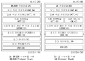
- FIG. 3 is a diagram illustrating an example of a Bluetooth communication architecture to which the methods proposed herein may be applied.
- FIG. 3 shows an example of a protocol stack of Bluetooth Basic Rate (BR) / Enhanced Data Rate (EDR), and (b) shows a protocol stack of Bluetooth Low Energy (LE). An example is shown.
- BR Basic Rate
- EDR Enhanced Data Rate
- LE Bluetooth Low Energy
- the Bluetooth BR / EDR protocol stack has an upper controller stack 10 and a lower controller stack based on a host controller interface HCI 18. It may include a host stack (20) of.
- the host stack (or host module) 20 refers to a wireless transceiver module for receiving a 2.4 GHz Bluetooth signal and hardware for transmitting or receiving a Bluetooth packet. Control and perform actions.
- the controller stack 10 may include a PHY layer 12, a link controller layer 14, and a link manager layer 16.
- the PHY layer 12 is a layer that transmits and receives a 2.4 GHz radio signal.
- PFS layer Global System for Mobile Communications
- the PHY layer 12 may transmit data by hopping 79 RF channels.
- the link controller layer 14 is responsible for transmitting a digital signal, selects a channel sequence hopping 1400 times per second, and transmits a 625us length time slot for each channel.
- the link manager layer 16 controls the overall operation (link setup, control, security) of the Bluetooth connection by using a link manager protocol (LMP).
- LMP link manager protocol
- the link manager layer 16 may perform the following functions.
- the host controller interface layer 18 provides an interface between the host module and the controller module so that the host can provide commands and data to the controller, and the controller can provide events and data to the host.
- the host stack (or host module) 20 may include a logical link control and adaptation protocol (L2CAP, 21), an attribute protocol (Protocol, 22), a generic attribute profile (GATT, 23), and a generic access profile. Profile, GAP, 24), BR / EDR profile 25.
- L2CAP logical link control and adaptation protocol
- Protocol 22
- GATT generic attribute profile
- GAP BR / EDR profile
- the logical link control and adaptation protocol (L2CAP) 21 may provide one bidirectional channel for transmitting data to a specific protocol or profile.
- the L2CAP 21 may multiplex various protocols, profiles, etc. provided by a higher layer of Bluetooth.
- L2CAP of Bluetooth BR / EDR uses dynamic channel, supports protocol service multiplexer, retransmission, streaming mode, and provides segmentation, reassembly, per-channel flow control, and error control.
- the generic attribute profile (GATT) 23 may be operable as a protocol describing how the attribute protocol 22 is used in the construction of services.
- the general attribute profile 23 may be operable to specify how ATT attributes are grouped together into services, and may be operable to describe features associated with the services.
- the generic attribute profile 23 and the attribute protocol ATT 22 may use features to describe the state and services of a device and to describe how features relate to each other and how they are used.
- the attribute protocol 22 and the BR / EDR profile 25 define a service profile using Bluet BR / EDR and an application protocol for sending and receiving these data, and the Generic Access Profile. , GAP, 24) defines device discovery, connectivity, and security levels.
- the Bluetooth LE protocol stack is a controller stack 30 operable to handle timing-critical radio interface and a host operable to process high level data. It contains a stack (Host stack, 40).
- the controller stack 30 may be implemented using a communication module that may include a Bluetooth radio, for example, a processor module that may include a processing device such as a microprocessor.
- the host stack may be implemented as part of an OS running on a processor module, or as an instance of a package on the OS.
- controller stack and the host stack can be operated or executed on the same processing device in the processor module.
- the controller stack 30 includes a physical layer (PHY) 32, a link layer 34, and a host controller interface 36.
- PHY physical layer
- link layer 34 link layer
- host controller interface 36 host controller interface
- the physical layer (PHY) 32 is a layer that transmits and receives a 2.4 GHz radio signal and uses GFSK (Gaussian Frequency Shift Keying) modulation and a frequency hopping technique composed of 40 RF channels.
- GFSK Gausian Frequency Shift Keying
- the link layer 34 which transmits or receives a Bluetooth packet, creates a connection between devices after performing advertising and scanning functions using three advertising channels, and generates up to 257 bytes of data packets through 37 data channels. Provides the ability to send and receive.
- the host stack includes a logical link control and adaptation protocol (L2CAP, 41), a security manager (SM, 42), an attribute protocol (Attribute Protocol, ATT, 43), a generic attribute profile (GATT, 44). It may include a Generic Access Profile (45), LE Profile (46). However, the host stack 40 is not limited to this and may include various protocols and profiles.
- the host stack uses L2CAP to multiplex the various protocols, profiles, etc. provided by Bluetooth.
- L2CAP Logical Link Control and Adaptation Protocol 41 may provide one bidirectional channel for transmitting data to a specific protocol or profile.
- the L2CAP 41 may be operable to multiplex data among higher layer protocols, segment and reassemble packages, and manage multicast data transmission.
- Bluetooth LE In Bluetooth LE, three fixed channels (one for the signaling channel, one for the Security Manager, and one for the Attribute protocol) are used by default. And, if necessary, the dynamic channel may be used.
- BR / EDR Base Rate / Enhanced Data Rate
- SM (Security Manager) 42 is a protocol for authenticating devices and providing key distribution.
- Attribute Protocol (ATT) 43 defines a rule for accessing data of a counterpart device in a server-client structure. ATT has six message types (Request, Response, Command, Notification, Indication, Confirmation).
- the Request message is a message for requesting and delivering specific information from the client device to the server device
- the Response message is a response message for the request message, which can be used for transmission from the server device to the client device.
- Command message A message sent mainly from the client device to the server device to indicate a command of a specific operation.
- the server device does not transmit a response to the command message to the client device.
- Notification message This message is sent from the server device to the client device for notification such as an event.
- the client device does not transmit a confirmation message for the notification message to the server device.
- Indication and Confirm message This message is transmitted from the server device to the client device for notification such as an event. Unlike the notification message, the client device transmits a confirmation message for the Indication message to the server device.
- the present invention transmits a value for the data length when a long data request is made in the GATT profile using the attribute protocol (ATT, 43) so that the client can know the data length clearly, and from the server using the UUID (Characteristic) Can receive the value.
- ATT attribute protocol
- UUID Consumer User Data
- the generic access profile 45 is a newly implemented layer for Bluetooth LE technology and is used to control role selection and multi-profile operation for communication between Bluetooth LE devices.
- the general access profile 45 is mainly used for device discovery, connection creation, and security procedures, and defines a method of providing information to a user, and defines the type of an attribute as follows.
- UUID Universal Unique Identifier, value type
- the LE profile 46 is mainly applied to a Bluetooth LE device as profiles having a dependency on GATT.
- the LE profile 46 may include, for example, Battery, Time, FindMe, Proximity, Time, and the like. Details of GATT-based Profiles are as follows.
- the generic attribute profile GATT 44 may be operable as a protocol describing how the attribute protocol 43 is used in the construction of services.
- the generic attribute profile 44 may be operable to specify how ATT attributes are grouped together into services, and may be operable to describe features associated with the services.
- the generic attribute profile 44 and the attribute protocol may use features to describe the state and services of a device, and how features relate to each other and how they are used.
- the BLE procedure may be classified into a device filtering procedure, an advertising procedure, a scanning procedure, a discovery procedure, a connecting procedure, and the like.
- the device filtering procedure is a method for reducing the number of devices performing a response to a request, an indication, a notification, etc. in the controller stack.
- the controller stack can control the number of requests sent, reducing power consumption in the BLE controller stack.
- the advertising device or scanning device may perform the device filtering procedure to limit the device receiving the advertising packet, scan request or connection request.
- the advertising device refers to a device that transmits an advertising event, that is, performs an advertisement, and is also referred to as an advertiser.
- the scanning device refers to a device that performs scanning and a device that transmits a scan request.
- the scanning device when the scanning device receives some advertising packets from the advertising device, the scanning device should send a scan request to the advertising device.
- the scanning device may ignore the advertisement packets transmitted from the advertisement device.
- the device filtering procedure may also be used in the connection request process. If device filtering is used in the connection request process, it is not necessary to transmit a response to the connection request by ignoring the connection request.
- the advertising device performs an advertising procedure to perform a non-directional broadcast to the devices in the area.
- non-directional broadcast refers to broadcast in all directions rather than broadcast in a specific direction.
- Non-directional broadcasts refer to broadcasts in a particular direction. Non-directional broadcasts occur without a connection procedure between an advertising device and a device in a listening (or listening) state (hereinafter referred to as a listening device).
- the advertising procedure is used to establish a Bluetooth connection with a nearby initiating device.
- the advertising procedure may be used to provide periodic broadcast of user data to the scanning devices that are listening on the advertising channel.
- the advertising devices may receive a scan request from listening devices that are listening to obtain additional user data from the advertising device.
- the advertising device transmits a response to the scan request to the device that sent the scan request through the same advertising physical channel as the received advertising physical channel.
- Broadcast user data sent as part of an advertisement packet is dynamic data, while scan response data is generally static data.
- the advertising device may receive a connection request from the initiating device on the advertising (broadcast) physical channel. If the advertising device used a connectable advertising event and the initiating device was not filtered by the device filtering procedure, the advertising device stops the advertising and enters the connected mode. The advertising device may start advertising again after the connected mode.
- the device performing the scanning i.e., the scanning device, performs a scanning procedure to listen to the non-directional broadcast of the user data from the advertising devices using the advertising physical channel.
- the scanning device sends a scan request to the advertising device via the advertising physical channel to request additional data from the advertising device.
- the advertising device transmits a scan response that is a response to the scan request, including additional data requested by the scanning device over the advertising physical channel.
- the scanning procedure can be used while connected to other BLE devices in the BLE piconet.
- the scanning device If the scanning device is in an initiator mode that can receive the broadcasted advertising event and initiate a connection request, the scanning device sends the connection request to the advertising device via the advertising physical channel to the advertising device. You can start a Bluetooth connection with.
- the scanning device When the scanning device sends a connection request to the advertising device, the scanning device stops initiator mode scanning for further broadcast and enters the connected mode.
- Bluetooth devices Devices capable of Bluetooth communication (hereinafter referred to as “Bluetooth devices”) perform an advertisement procedure and a scanning procedure to find devices that are nearby or to be found by other devices within a given area.
- the discovery procedure is performed asymmetrically.
- a Bluetooth device that attempts to find another device around it is called a discovering device and listens for devices that advertise a scannable advertisement event.
- Bluetooth devices discovered and available from other devices are referred to as discoverable devices, and actively broadcast advertising events so that other devices can scan through an advertising (broadcast) physical channel.
- Both the discovering device and the discoverable device may already be connected with other Bluetooth devices in the piconet.
- connection procedure is asymmetric, and the connection procedure requires the other Bluetooth device to perform the scanning procedure while the specific Bluetooth device performs the advertisement procedure.
- the advertising procedure can be the goal, so that only one device will respond to the advertising.
- the connection may be initiated by sending a connection request to the advertising device via the advertising (broadcast) physical channel.
- the link layer LL enters the advertisement state by the instruction of the host (stack). If the link layer is in the advertisement state, the link layer sends advertisement packet data units (PDUs) in the advertisement events.
- PDUs advertisement packet data units
- Each advertising event consists of at least one advertising PDU, which is transmitted via the advertising channel indexes used.
- the advertisement event may terminate when the advertisement PDU is transmitted through each of the advertisement channel indexes used, or may terminate the advertisement event earlier when the advertisement device needs to make space for performing another function.
- the link layer enters the scanning state by the indication of the host (stack). In the scanning state, the link layer listens for advertising channel indices.
- scanning states There are two types of scanning states: passive scanning and active scanning, each scanning type being determined by the host.
- ScanInterval is defined as the interval (interval) between the starting points of two consecutive scan windows.
- the link layer must listen for completion of all scan intervals in the scan window as instructed by the host. In each scan window, the link layer must scan a different advertising channel index. The link layer uses all available advertising channel indexes.
- the link layer When passive scanning, the link layer only receives packets and does not transmit any packets.
- the link layer When active scanning, the link layer performs listening to rely on the advertising PDU type, which may request advertising PDUs and additional information related to the advertising device from the advertising device.
- the link layer enters the initiation state by the indication of the host (stack).
- the link layer When the link layer is in the initiating state, the link layer performs listening for the advertising channel indexes.
- the link layer listens for the advertising channel index during the scan window period.
- the link layer enters the connected state when the device performing the connection request, i.e., the initiating device, sends the CONNECT_REQ PDU to the advertising device or when the advertising device receives the CONNECT_REQ PDU from the initiating device.
- connection After entering the connected state, the connection is considered to be created. However, it does not need to be considered to be established at the time the connection enters the connected state. The only difference between the newly created connection and the established connection is the link layer connection supervision timeout value.
- the link layer that performs the master role is called a master, and the link layer that performs the slave role is called a slave.
- the master controls the timing of the connection event, and the connection event is the point in time when the master and the slave are synchronized.
- BLE devices use the packets defined below.
- the link layer has only one packet format used for both advertisement channel packets and data channel packets.
- Each packet consists of four fields: Preamble, Access Address, PDU, and CRC.
- the PDU When one packet is sent on an advertising physical channel, the PDU will be an advertising channel PDU, and when one packet is sent on a data physical channel, the PDU will be a data channel PDU.
- Advertising channel PDU (Advertising Channel PDU )
- the advertising channel PDU Packet Data Unit
- PDU Packet Data Unit
- the PDU type field of the advertising channel PDU included in the header indicates a PDU type as defined in Table 1 below.
- Advertising PDU (Advertising PDU )
- advertising channel PDU types are called advertising PDUs and are used in specific events.
- ADV_IND Connectable Non-Oriented Ads Event
- ADV_DIRECT_IND Connectable Directional Advertising Event
- ADV_NONCONN_IND Non-Connectable Non-Oriented Ads Event
- ADV_SCAN_IND Scannable Non-Oriented Ads Event
- the PDUs are transmitted at the link layer in the advertisement state and received by the link layer in the scanning state or initiating state.
- the advertising channel PDU type below is called a scanning PDU and is used in the state described below.
- SCAN_REQ Sent by the link layer in the scanning state and received by the link layer in the advertising state.
- SCAN_RSP Sent by the link layer in the advertising state and received by the link layer in the scanning state.
- the advertising channel PDU type below is called the initiating PDU.
- CONNECT_REQ Sent by the link layer in the initiating state and received by the link layer in the advertising state.
- the data channel PDU has a 16-bit header, payloads of various sizes, and may include a message integrity check (MIC) field.
- MIC message integrity check
- the procedure, state, packet format, etc. in the BLE technology may be applied to perform the methods proposed herein.
- FIG. 4 is a diagram illustrating an example of a structure of a GATT profile of Bluetooth low power energy.
- the GATT Generic Attribute Profile
- a peripheral device for example, a sensor device serves as a GATT server, and has a definition of a service and a characteristic.
- the GATT client sends a data request to the GATT server, and all transactions begin at the GATT client and receive a response from the GATT server.
- the GATT-based operating structure used in the Bluetooth LE is based on Profile, Service, and Characteristic, and may form a vertical structure as shown in FIG. 5.
- the profile consists of one or more services, and the service may consist of one or more features or other services.
- the service divides data into logical units and may include one or more characteristics or other services.
- Each service has a 16-bit or 128-bit identifier called the Universal Unique Identifier (UUID).
- UUID Universal Unique Identifier
- the characteristic is the lowest unit in the GATT based operation structure.
- the property contains only one data and has a UUID of 16 bits or 128 bits similar to the service.
- the property is defined as a value of various pieces of information and requires one attribute to contain each piece of information. Multiple properties of the above properties can be used.
- the attribute consists of four components and has the following meaning.
- Type the type of attribute
- the present invention proposes a method for controlling a device by acquiring information related to controllable operation and combination information of a device to be controlled by a control device through the GATT.
- FIG. 5 is a flowchart illustrating a method of forming a connection using Bluetooth Low Energy (LE) between devices.
- LE Bluetooth Low Energy
- the first device 300 transmits an advertising message to the second device for the Bluetooth LE connection between the first device 300 and the second device 400. (S5010).
- the advertisement message may be transmitted by a broadcast method or a unicast method.
- the advertisement message is used to provide its own information to other devices using Bluetooth LE, and may include various information such as service information and user information provided by the device.
- the second device 400 may discover the first device 300 through the advertisement message.
- the second device 400 After checking the information included in the advertisement message, the second device 400 transmits a connection request message for requesting a Bluetooth LE connection to the first device 300 (S5020).
- the first device 300 and the second device 400 form a Bluetooth Low Energy (LE) connection (S5030).
- LE Bluetooth Low Energy
- the present invention proposes a method for proposing the first device 300 and the second device 400 by using a third device to solve such a problem.
- FIG. 6 is a view briefly illustrating a method for controlling another device through a control device proposed in the present specification.
- a third device 500 is required, and the third device 500 is the first device.
- a new control protocol is needed to control the association of the device 300 and the second device 400.
- a control device for controlling the operations of the first device 300 and the second device 400 is referred to as the third device 500.
- the third device 500 needs to know information (eg, interface information, service information, etc.) of the devices in order to control the operation of the devices.
- information e.g, interface information, service information, etc.
- FIGS. 7 and 8 are diagrams illustrating an example of a profile structure for providing a service for controlling a device proposed in the present specification.
- a service for controlling another device by the control device may be included in a profile of other services or may be defined as a separate profile.
- an easy pairing service a service for controlling other devices by the control device.
- the third device 300 which is the control device may control other devices through the easy pairing service.
- the third device 300 may control operations related to coupling (eg, connection, pairing, or bonding) between the first device 300 and the second device 400 through the easy pairing service. Can be.
- the easy pairing service may be included in a profile of another service as shown in FIG. 7 or may be defined as a separate profile as shown in FIG. 8.
- the easy pairing service is not defined as a separate profile but included in a profile of a specific service, an operation of one application may be easily described.
- the easy pairing service cannot be applied to a service of a profile not including the easy pairing service, and roles between devices must be clearly defined.
- the server / client structure is compatible at the profile level, and the easy pairing service can be extended to another profile.
- This property is used to provide server controllable operation information for pairing and connection.
- the operation of the server is defined in the Generic Access Profile (GAP), which defines the general procedures for device discovery and link management aspects of connecting to Bluetooth devices.
- GAP Generic Access Profile
- the information provided by the property is used by the client to control the server operation of the procedure.
- Table 2 below shows the fields of the supported pairing function characteristics.
- Supported pairing function characteristics are identified using the UUID «Supported pairing functions».
- the GAP Action field identifies the general Bluetooth action supported by the server.
- the general operation is defined in the GAP part of the Bluetooth Core Specification.
- Bits of the GAP field may be defined as shown in Table 3 below.
- the server For each bit in Table 3, the server sets the bit to 1 if it supports the specified operation. Otherwise, the bit is set to zero.
- the server then sets the reserved bit for the future to zero.
- the Easy Pairing (EP) Operation field identifies an optional easy pairing function supported by the server.
- Bits of the EP operation field may be defined as shown in Table 4 below.
- bit 1 in Table 4 For each bit in Table 4, the server sets the bit to 1 if the server supports the specified function. Otherwise, the bit is set to zero. When bit 18 is set to 1 in Table 3, bit 1 in Table 4 is set to 1.
- the server then sets the reserved bit for the future to zero.
- the pairing control point feature is used by the client to manage the pairing / connection of the server.
- the structure of the pairing control point characteristic may be defined as shown in Table 5 below.
- FIG. 9 is a diagram illustrating an operation of a control point characteristic as an embodiment to which the present invention may be applied.
- the control device transmits an ATT write request message to the first device connected to the control device (S901).
- the write request message includes a control point operation code (OP code).
- OP code control point operation code
- the first device transmits an ATT write response message to the control device (S902).
- the write response message may include an ATT result value.
- the first device and the second device perform a GAP operation (S903).
- the first device and the second device perform the GAP operation requested by the control device.
- the first device transmits an ATT indication message to the control device (S904).
- the indication message may include a result code related to the result of the GAP operation.
- the control device transmits an ATT confirmation message to the first device (S905).
- the confirmation message may include an ATT result value.
- the operation of the control point characteristic is composed of two GATT procedures, Write Characteristic Value and Characteristic Value Indications.
- the first GATT procedure, the write characteristic value is a request for a GAP operation of the server, and the ATT write response protocol data unit (PDU) is a response PDU of an ATT write request, which may be an ATT error response.
- PDU ATT write response protocol data unit
- Some of the control point procedures may require the operation of the requested GAP. It requires additional link layer states such as Inquiry, Inquiry Scan, Paging, Paging Scan, Advertising, or Scanning. GAP operations are used to interact with other devices.
- C5 Required if more than 512 bytes are supported for all client list information.
- the pairing control point feature provides a mechanism for the client to command the server's behavior using the GATT Write Characteristic Value subprocedure.
- the procedure is triggered by writing a value containing an opcode representing the action following a valid parameter in the context of that opcode.
- the server should instruct the client using the control point response indication with a success result code. If the procedure did not complete successfully, the server should instruct the client using the control point response indication with an error response code.
- the acceptor role accepts the initiator's request for device discovery and connection establishment procedures.
- the acceptor is in Limited Discoverable Mode or General Discoverable Mode, the acceptor is discovered by the initiator device. Otherwise, the acceptor is not retrieved because it does not respond to the initiator's query.
- the acceptor accepts the link establishment procedure from the initiator and creates a BR / EDR link connection between them. Otherwise, the acceptor does not respond to the initiator and therefore does not associate with the initiator. When the acceptor performs a pairing process with the initiator, it creates a link connection and then one or more shared secret keys with the initiator.
- the server must store the generated key after the pairing process for subsequent connections to form a trusted device pair.
- control point messages need additional parameters to control the possible behavior of the server.
- the parameter consists of an operation field and an optional peer device ID field as shown in Table 7 below.
- the operation field is bit-based information for limited searchable mode, general searchable mode, connectable mode, bonding mode, Confirm Value Indication and Confirm Value Relay.
- the peer device ID field is an optional field for determining the peer device.
- the operation field may be defined as shown in Table 8.
- the server is set to searchable mode, connectable mode and bondable mode, as defined in bit 0, bit 1, bit 2 and bit 3 of the operation subfield of Table 8.
- the server MUST NOT be set to a value reserved for future use on these bits.
- bit 4 is set to 1, the server must perform the acceptor operation with the peer device with the device address of the next peer device ID field value. Otherwise, the peer device ID field does not exist and the server can accept the request of all devices.
- bit 5 is set to 1, the server must instruct the client to relay the confirmation value to the peer server. Otherwise, the server does not display a confirmation value.
- bit 6 is set to 1, the server receives the confirmation value of the peer server through the client along with the confirmation value relay. Otherwise, the server does not receive a confirmation value relay from the client.
- This procedure is supported if the server supports a known (obtained) initiator role in the GAP operation fields (bits 4 and 5) of the supported pairing capability.
- the initiator role initiates the Link Establishment Procedure and Bonding procedure on the acceptor device.
- This control procedure requires additional parameters to control the possible behavior of the server.
- the parameter may be composed of an operation field and a peer device ID field as shown in Table 9 below.
- the procedure uses the peer device ID field to identify what the server will connect to.
- the operation field is bit-based information about a link establishment procedure, a bonding procedure, a confirm value indication, and a confirm value relay. Each action is mapped to a separate bit in this field.
- the operation field may be defined as shown in Table 10 below.
- the server For each bit in Table 10, the server performs each task if each bit is set to 1. Otherwise, the server does not perform each task.
- bit is set to zero.
- This procedure is supported if the server supports a known (obtained) peripheral role in the GAP operation fields (bit 8, bit 9, bit 10 and bit 11) in the supported pairing function characteristics.
- the peripheral role device advertises the device in the central role to discover and accepts the connection request in the central role.
- the advertising operation is associated with a discoverable mode and a connectable mode. If the server is in a direct connectable advertising mode, the server receives a connection request from the central device identified in the advertising message. If the server is in undirected connectable advertising mode, the server can receive connection requests from all central devices.
- Advertising behavior of the server is controlled by the client.
- the duration of advertisements on the server is controlled by the client.
- the client controls whether the server uses direct connectable mode or undirect connectable mode while advertising.
- the client controls whether the server uses a random address during the advertisement.
- the client also controls pairing and bonding operations of the server after the server is connected to the peer device.
- this procedure requires a parameter including an operation field, an optional peer device ID field, and an optional peer device identifier resolving key (IRK) field as shown in Table 11.
- a parameter including an operation field, an optional peer device ID field, and an optional peer device identifier resolving key (IRK) field as shown in Table 11.
- the peer device ID is provided when the direct connection mode is selected in the operation field.
- the operation field is bit-based information about searchable mode, connectable mode, privacy mode, bondable mode, confirmation value indication, relay value indication, and identity analysis key operation.
- the operation field may be defined as shown in Table 12 below.
- the server may be set to a searchable mode as defined in bit 0 and bit 1 of the operation subfield.
- the server is not set to this reserved value for future use.
- the server may be set to the connectable mode as defined by bits 3 and 4 of the operation subfield. If the value is 01b, the server may operate in the direct connection mode by using the value of the peer device ID field as the initiator's address. The server is not set to this reserved value for future use.
- the server advertises the advertiser's address type as defined in bits 6 and 7 of the action subfield. If the server has a resolvable private address only characteristic, the server advertises with a resolvable private address. If the peer device does not have an Identity Resolvable Key, the peer device may ignore the advertisement of this server.
- the server may be set to a bondable mode as defined in bit 9 of the operation subfield. Otherwise, the server will not be set in bondable mode.
- bit 10 is set to 1, the server instructs the client to confirm (relay) the confirmation value to the peer server. Otherwise, the server does not indicate a confirmation value.
- bit 11 is set to 1, the server receives the confirmation value of the peer server through the client along with the confirmation value relay. Otherwise, the server does not receive confirmation value relay from the client.
- the server When bit 12 is set to 1, the server receives a peer device identity resolving key (IRK) field which is an IRK value of a peer device ID. The server adds the peer device ID, peer device IRK, and local IRK to the resolving list of the device. Otherwise, the server does not receive the peer device IRK field.
- IRK peer device identity resolving key
- Bits reserved for the future are set to zero.
- This procedure is supported if the server supports a known (obtained) central role in the GAP operation fields (bits 12 and 13) of the supported pairing capability.
- the central role device receives the peripheral's advertisement and sends a connection request to the peripheral to form a connection.
- Server operation procedures such as connection establishment procedure, bonding procedure, confirm value indication and confirm value relay are controlled by the client.
- the connection establishment procedure of the server is controlled by the client by an operation consisting of an Auto Connection Establishment or a General Connection Establishment Procedure.
- the automatic connection establishment procedure of the server allows the server to automatically connect to a specific LE device without client interaction after performing this procedure.
- the server can connect with a particular LE device once with this procedure.
- the operation of the server such as a bonding procedure, confirmation value indication or confirmation value relay, can then be controlled by the client after the link layer connection is established to the server.
- this procedure requires a parameter including an operation field, a peer device ID field, and an optional peer device IRK as shown in Table 13 below.
- the peer device ID field is a device address of a Bluetooth device to connect.
- the operation may be defined as shown in Table 14 below.
- the server may be configured as a connection establishment procedure as defined by bit 0 and bit 1 of the operation subfield. If the value is 00b (automatic connection establishment procedure), the server automatically establishes a connection with the specific device via the LE transport. This procedure works on the controller side without interacting with the host. Thus, after receiving this Control Point message, the server can automatically connect to a specific device without interacting with the client. If the value is 01b (general connection establishment procedure), the server creates a connection once according to this control point procedure. The server is not set to this reserved value for future use.
- bit 2 is set to 1, the server starts the bonding procedure to store the bonding information for the next connection with the peer device after the pairing process.
- the server may instruct the client to confirm the confirmation value to relay to the peer server. Otherwise, the server may not present a confirmation value to the client.
- bit 4 is set to 1, the server may receive the confirmation value of the peer server with the confirmation value relay from the client. Otherwise the server may not receive the confirmation value relay from the client.
- the server may initiate using the address type of the initiator, as defined in bits 5 and 6 of the operation subfield. If the server has a private address resolvable private property, the server should initialize with a resolvable private address. If the peer device does not have an identity resolvable key, the peer device may ignore the connection request from this server.
- the server may receive a peer device IRK field containing the IRK value of the peer device ID in this procedure.
- the server can add the peer device ID, peer device IRK, and local IRK to the analysis list. Otherwise, the server does not receive the ID resolution key field.
- control point procedures are performed based on actions. That is, the control point procedure is performed separately according to each mode or procedure based on the GAP operation.
- each step of the Discoverable Mode Setup Procedure, the Connectable Mode Setup Procedure, the Connection Request Procedure, and the Connection Termination Separate commands (or control point characteristics) are transmitted by the control device.
- the Discovery Mode Setup Procedure ie, Normal or Limited Searchable Mode
- the Connectable Mode Setup Procedure ie, Direct or Undirected Connectable Mode
- the present invention proposes a control point procedure based on a GAP role.
- an efficient control can be performed by transmitting a command that has been performed through several existing procedures (or steps) at once.
- GAP roles define the device's behavior from discovery to connection establishment.
- the GAP role may be defined as follows.
- Initiator (or Initiator): sends an inquiry message to initiate a search of the device and receives a response message.
- Acceptor Receives a query message from the initiator and sends a response message to the query message.
- Peripheral Sends an advertisement and receives a connection request from Central.
- Central Receives an advertisement from the peripheral and sends a connection request to the peripheral based on the received advertisement.
- control device ie, the client device
- the control device may control a plurality of operations of the first device (ie, the server device) with one command.
- a bearer field for indicating a connection type (BR / EDR transport or LE transport) may be deleted from the control point characteristic.
- the range of the opcode value may be 256.
- an operation code (or control point characteristic) may be defined for each role (BR / EDR initiator, BR / EDR acceptor, LE peripheral, LE central).
- the opcode may include a parameter indicating a GAP role and a plurality of operations based on each GAP role.
- the opcode may include a role field indicating a GAP role and a parameter field indicating a plurality of operations. Each operation may be indicated by an independent bit by parameters of the parameter.
- the procedure for controlling the BR / EDR acceptor role may consist of one opcode.
- the opcode may include an additional parameter for controlling possible operations of the first device (ie, the server device).
- the procedure may be supported if the first device is indicated to support the acceptor role in the GAP operation field of the supported pairing function characteristic.
- the opcode for controlling the role of the BR / EDR acceptor may include parameters indicating a discoverable mode operation, a connectable mode operation, and / or a bondable mode operation. have. In this case, each operation may be mapped to a separate bit.
- the discoverable mode may be divided into a non-discoverable mode, a limited discoverable mode, or a general discoverable mode.
- the acceptor may be discovered by the initiator device. Otherwise, the acceptor may not be retrieved because it does not respond to the initiator's query.
- the acceptor may accept the link establishment procedure from the initiator to form a BR / EDR link connection between them. Otherwise, the acceptor may not make a connection with the initiator because it does not respond to the initiator.
- the acceptor When the acceptor performs the pairing process, it can create one or more shared secret keys with the initiator after creating the link connection.
- the server may store the generated key after the pairing process for subsequent connections to form a trusted device pair.
- the procedure for controlling the BR / EDR initiator role may consist of one opcode.
- the opcode may include additional parameters for controlling possible operations of the first device (ie, the server device).
- the above procedure may be supported when the first device is indicated to support the initiator role in the GAP operation field of the supported pairing function characteristic.
- the opcode for controlling the BR / EDR initiator role may include parameters indicating operation of a link establishment procedure, a bonding procedure, and / or a pairing procedure. In this case, each operation may be mapped to a separate bit.
- control device may set a parameter field indicating a link establishment procedure to a value of 1 in an opcode indicating a BR / EDR initiator role, a parameter field representing a bonding procedure to a value of 1, and a device in an initiator role.
- the device in the initiator role may initiate a link establishment procedure and a bonding procedure to the acceptor device via the BR / EDR transport.
- the procedure for controlling the LE peripheral role may consist of one opcode.
- the opcode may include additional parameters for controlling possible operations of the first device (ie, the server device).
- the procedure may be supported when the first device is indicated to support the peripheral role in the GAP operation field of the supported pairing function characteristic.
- Opcodes for controlling LE peripheral roles are parameters that indicate discoverable mode operation, connectable mode operation, privacy mode operation, and / or bondable mode operation. Can include them. In this case, each operation may be mapped to a separate bit.
- the advertising behavior of the LE peripheral is associated with a discoverable mode and a connectable mode.
- the searchable mode may be divided into a general discoverable mode and a limited discoverable mode.
- the connectable mode may be classified into a direct connectable advertising mode and an undirected connectable advertising mode.
- the peripheral receives a connection request from the central device identified in the advertising message.
- the peripheral may receive a connection request from all central devices.
- Advertising behavior of peripherals such as Discoverable Mode, Connectable Mode, and Privacy Mode may be controlled by the client.
- the advertisement duration of the server in General Discoverable Mode and Limited Discoverable Mode may be controlled by the client.
- the client may control whether the server (ie, peripheral) uses direct connectable mode or undirect connectable mode while advertising. In addition, the client may control whether the server uses a random address while advertising. The client may also control pairing and bonding operations of the server after the server is connected to the peer device.
- a parameter including an operation field, an optional peer device ID field, and an optional peer device identification resolving key (IRK) field may be needed as shown in Table 11 described above.
- the peer device ID is provided when the direct connection mode is selected. The privacy mode operation using the IRK of the peer device will be described in detail later.
- the procedure for controlling the LE Central role can consist of one Opcode.
- the opcode may include additional parameters for controlling possible operations of the first device (ie, the server device).
- the procedure may be supported if the first device is indicated to support a central role in the GAP operation field of the supported pairing function characteristic.
- the opcode for controlling the LE central role may include parameters for indicating a connection establishment procedure and / or bondable procedure operation. In this case, each operation may be mapped to a separate bit.
- connection establishment procedure may be divided into an auto connection establishment procedure or an general connection establishment procedure.
- Central can automatically connect to a particular LE device without interaction with the client. In other words, after receiving the control point message indicating the automatic connection establishment procedure, Central may automatically connect to a specific device without further interaction with the client. However, if a generic connection establishment procedure is performed, after Central performs the generic connection establishment procedure, operations such as a bonding procedure may be controlled by the client after the link layer connection is established. In other words, after receiving the control point message indicating the general connection establishment procedure, the Central creates a connection once according to the control point procedure.
- this procedure may require parameters including an operation field, a peer device ID field, and an optional peer device IRK as shown in Table 13 above.
- the peer device ID field indicates a device address of the partner Bluetooth device to which the connection will be performed.
- the first device may start the bonding procedure to store bonding information for the next connection with the peer device after the pairing process.
- FIG. 10 is a flowchart illustrating a method of controlling a device-to-device connection using a control device according to an embodiment to which the present invention is applied.
- the control device may form a Bluetooth connection with the first device (S1001).
- the Bluetooth connection may be formed by Bluetooth BR / EDR or Bluetooth LE.
- the control device transmits a read request message requesting characteristic information related to an operation supported by the first device to the first device (S1002), and the first device reads the characteristic information in response to the read request message.
- the response message is transmitted to the control device (S1003).
- control device receives controllable operation information of the first device for pairing and connection from the first device (or server device).
- the information provided by the property is used by the control device to control the role and operation of the first device.
- the characteristic information may include an operation field indicating an operation supported by the first device.
- the operation field may include at least one of a connection type, a role, a mode, or a procedure supported by the first device.
- the control device transmits a write request message requesting the writing of a characteristic for instructing the performance of a specific role to the first device based on the characteristic information (S1004).
- the characteristic may be a pairing control point characteristic used by the client device to manage pairing and connection of the server.
- the write request message may include control information related to the specific role.
- the control information may include role information indicating the specific role and parameter information indicating an operation related to the specific role.
- the structure of the control point characteristic for controlling the first device may be configured to include role information indicating a role of the first device and parameters indicating operations related to the role.
- the specific role may be any one of an acceptor of a Bluetooth BR / EDR, an initiator of a Bluetooth BR / EDR, a peripheral of a Bluetooth LE, and a central of a Bluetooth LE.
- the parameter information may include a plurality of mode information and / or procedure information for the first device to perform operations requested from the control device with a peer device.
- the control information may include a discoverable mode operation, a connectable mode operation, and a bondable mode. It may include parameters indicating an operation.
- control information may include parameters indicating a link establishment procedure and a bonding procedure.
- the control information is a searchable mode operation (Discoverable mode operation, Connectable mode operation and Bondable mode operation (Bondable mode operation) It may include indicating parameters.
- control information may include parameters for instructing a connection establishment procedure and a bondable procedure.
- the first device transmits a write response message to the control device in response to the write request message (S1005).
- the write response message may include a result code indicating a result of performing a specific role according to the write request.
- a role and related operations into one command (e.g., a discoverable mode and a connectable mode, which are operations (or modes) related to an advertisement procedure of a Bluetooth LE).
- a command e.g., a discoverable mode and a connectable mode, which are operations (or modes) related to an advertisement procedure of a Bluetooth LE.
- a bearer type subfield (1 byte) for indicating a connection type (BR / EDR transport or LE transport) may be deleted from the control point characteristic. Can be.
- FIG. 11 is a flowchart illustrating a method of controlling an LE connection between devices using a control device according to an embodiment to which the present invention may be applied.
- the control device receives an advertisement message from the first device (S1101).
- the control device transmits a connection request message to the first device based on the advertisement message (S1102).
- the control device transmits a read request message requesting a pairing function characteristic to the first device (S1103).
- control device sends a read request message to the first device to request supportable operation information supported by the first device.
- the first device transmits a read response message including the pairing function characteristic to a control device (S1104).
- the first device transmits information related to operations supported by the first device to the control device.
- the read response message may include an operation field indicating an operation supported by the first device, and the operation field may include at least one of a connection type, a role mode, or a procedure supported by the first device. Can be.
- the control device transmits a write request message requesting writing of a pairing control point characteristic instructing to perform the central role and related operations to the first device (S1105), and the first device responds to the write request message.
- the write response message is transmitted (S1106).
- the opcode for controlling the LE central role may include parameters for indicating a connection establishment procedure and / or bondable procedure operation. In this case, each operation may be mapped to a separate bit.
- control point procedure may be performed by the same procedure as the above-described steps S1101 to S1106.
- the control device receives the advertisement message from the second device (S1107).
- the control device transmits a connection request message to the second device based on the advertisement message (S1108).
- the control device transmits a read request message requesting a pairing function characteristic to the second device (S1109).
- the second device transmits a read response message including the pairing function characteristic to a control device in operation S1110.
- the control device transmits a write request message requesting writing of a pairing control point characteristic instructing performance of the peripheral role and related operations to the second device (S1111), and the second device responds to the write request message.
- the write response message is transmitted (S1112).
- the Opcode for controlling the LE peripheral role indicates a discoverable mode operation, a connectable mode operation, a privacy mode operation, and / or a bondable mode operation. Parameters may be included, and each operation may be mapped to a separate bit.
- Steps S1107 to S1112 are optional steps and may be omitted. That is, the control device may perform a control point procedure for a device performing a LE central role or a device performing an LE peripheral role, but the first device (or server device) and the second device (or peer device) must be performed. It is not necessary to perform control point procedures for all.
- the first device and the second device perform a connection procedure based on the control point characteristic received from the control device.
- the second device transmits an advertisement message to the first device (S1113).
- the second device When the second device receives a write response request message of a control point characteristic indicating an LE peripheral role and related operations from a control device, the second device may transmit an advertisement message based on the control point. .
- the first device and the second device form a connection based on the advertisement message and the control point received from the control device (S1114).
- the first device and / or the second device transmits an indication message to the control device in operation S1115.
- the indication message may include a result code indicating a result of performing a connection procedure between the first device and the second device.
- control device can instruct the first device to operate in a privacy mode.
- control point procedure using the IRK will be described.
- the type of Bluetooth address in the LE transport can be divided into a public device address and a random device address.
- the arbitrary device address may be divided into a static device address and a private device address.
- the dedicated device address is divided into non-resolvable and resolvable.
- an identity resolving key IRST
- the IRK is necessary for generating or analyzing a resolvable private address (RPA).
- RPA resolvable private address
- the IRK pair may be used for the local device and the peer device to resolve each other's device address.
- the address of a device that is any address can be resolved only if there is an IRK.
- the first device may instruct the control device whether or not the privacy function is supported through a supported pairing feature characteristic to indicate a supportable operation of the first device (ie, the server device).
- pairing control points can be used to manage the connection / pairing of LE peripherals and LE Central.
- the peer device's IRK may be added to the pairing control point.
- the device in the LE peripheral role may advertise with a resolvable private address. If the peer device does not have an IRK, the peer device may ignore the advertisement of the device in the LE peripheral role.
- the first device receives the peer device IRK indicating the IRK value of the peer device ID.
- the peer device IRK field may be included in the control point opcode described above.
- the first device may add the peer device ID, the peer device IRK, and the local IRK to the resolving list of the device.
- FIG. 12 is a flowchart illustrating a method of controlling a device-to-device connection using a control device according to an embodiment to which the present invention is applied.
- the control device forms a Bluetooth LE connection with the first device and obtains an IRK of the first device (S1201). Similarly, the control device forms an LE connection with the second device and acquires an IRK of the second device (S1202).
- the control device may obtain an IRK from the first device and / or the second device after establishing a Bluetooth LE connection.
- control device may generate an RPA and receive (or obtain) an IRK with each device to control the connection through the privacy mode between the first device and the second device.
- the control device performs a pairing function procedure supported with the first device and the second device (S1203).
- control device transmits a read request message including a pairing function characteristic supported for requesting information relating to controllable operations to the first device and the second device, wherein the first device and the second device are configured to perform the The read response message is sent in response to the read request message.
- the control device transmits a write request message requesting the writing of the pairing control point characteristic including the IRK of the second device (ie, the peer device) to the first device (S1204).
- the write request message may include role information indicating to perform an LE central role for the first device.
- the control device transmits a write request message requesting writing of a pairing control point characteristic including the IRK of the first device to the second device (S1205).
- the write request message may include role information indicating to perform an LE peripheral role with respect to the second device.
- the second device transmits an advertisement message including the RPA to the first device (S1206).
- the first device may analyze the RPA (or arbitrary address).
- the first device transmits a connection request message including its RPA to the second device by using the advertisement message and the analyzed address of the second device (S1207).
- the second device may analyze the RPA (or any address).
- the first device and the second device form a connection (S1208), and transmit a write response message to the control device (S1209, 1210).
- the write response message may include a result code indicating a result of performing a specific role according to the write request.
- Orientation-based device discovery method is not limited to the configuration and method of the embodiments described as described above, the embodiments are all or part of each of the embodiments is optional so that various modifications can be made It may be configured in combination.
- the direction-based device search method of the present specification may be implemented as processor-readable code in a processor-readable recording medium provided in a network device.
- the processor-readable recording medium includes all kinds of recording devices that store data that can be read by the processor. Examples of the processor-readable recording medium include ROM, RAM, CD-ROM, magnetic tape, floppy disk, optical data storage device, and the like, and may also be implemented in the form of a carrier wave such as transmission over the Internet. .
- the processor-readable recording medium can also be distributed over network coupled computer systems so that the processor-readable code is stored and executed in a distributed fashion.
Landscapes
- Engineering & Computer Science (AREA)
- Computer Networks & Wireless Communication (AREA)
- Signal Processing (AREA)
- Mobile Radio Communication Systems (AREA)
Abstract
블루투스 통신을 이용하여 제어 디바이스가 제 1 디바이스를 제어하는 방법 및 장치에 관한 것이다. 본 발명에 의하면, 상기 제 1 디바이스와 블루투스 연결을 형성하는 단계; 상기 제 1 디바이스가 지원하는 제어 가능한 동작(controllable operation)과 관련된 특성 정보를 요청하는 판독 요청 메시지를 상기 제 1 디바이스로 전송하는 단계; 상기 판독 요청 메시지에 대한 응답으로 상기 특성 정보를 포함하는 판독 응답 메시지를 상기 제 1 디바이스로부터 수신하는 단계로서, 상기 특성 정보는 상기 제 1 디바이스가 지원하는 동작을 나타내는 동작 필드를 포함하고; 상기 특성 정보에 기초하여 상기 제 1 디바이스로 특정 역할(role)의 수행을 지시하기 위한 특성의 기입을 요청하는 제 1 기입 요청 메시지를 전송하는 단계로서, 상기 제 1 기입 요청 메시지는 상기 특정 역할과 관련된 제어 정보를 포함하고; 및 상기 제 1 기입 요청 메시지에 대한 응답으로 기입 응답 메시지를 상기 제 1 디바이스로부터 수신하는 단계를 포함하되, 상기 제어 정보는 상기 특정 역할을 나타내는 역할 정보 및 상기 특정 역할과 관련된 동작을 나타내는 파라미터 정보를 포함할 수 있다.
Description
본 발명은 무선 통신시스템에서 근거리 기술인 블루투스를 이용하여 디바이스 간 커넥션을 형성하기 위한 방법 및 장치에 관한 것으로써, 특히 블루투스 기술을 이용하여 디바이스간 커넥션을 형성하기 위한 방법 및 장치에 관한 것이다.
블루투스는 근거리에서 각종 디바이스들을 무선으로 연결하여 데이터를 주고 받을 수 있는 근거리 무선 기술 규격이다. 블루투스(Bluetooth) 통신을 이용하여 두 기기간 무선 통신을 수행하고자 하는 경우, 사용자(User)는 통신하고자 하는 블루투스(Bluetooth) 디바이스(Device)들을 검색(Discovery)하고 연결(Connection)을 요청하는 절차를 수행한다. 본 발명에서 디바이스는 기기, 장치를 의미할 수 있다.
이때, 사용자는 블루투스 디바이스를 이용하여 사용하고자 하는 블루투스 통신방법에 따라 블루투스 디바이스를 검색한 후 연결을 수행할 수 있다.
블루투스 통신방법에는 BR/EDR (Basic Rate/Enhanced Data Rate)방식과 저전력 방식인 LE (Low Energy)방식이 있다. BR/EDR 방식은 블루투스 클래식 (Bluetooth Classic)라고 호칭될 수 있다. 블루투스 클래식 방식은 베이직 레이트(Basic Rate)를 이용하는 블루투스 1.0부터 이어져온 블루투스 기술과 블루투스 2.0에서부터 지원되는 인핸스드 데이터 레이트(Enhanced Data Rate)를 이용하는 블루투스 기술을 포함한다.
블루투스 저전력 에너지(Bluetooth Low energy, 이하 블루투스 LE라고 한다.)기술은 블루투스 4.0부터 적용되어 적은 전력을 소모하여 수백 키로바이트(KB)의 정보를 안정적으로 제공할 수 있다. 이러한 블루투스 저전력 에너지 기술은 속성 프로토콜(Attribute Protocol)을 활용해서 디바이스(Device) 간 정보를 교환하게 된다. 이러한 블루투스 LE 방식은 헤더의 오버헤드(overhead)를 줄이고 동작을 간단하게 해서 에너지 소비를 줄일 수 있다.
블루투스 기기들 중에는 디스플레이(Display)나 유저인터페이스(User Interface)가 없는 제품들도 있다. 다양한 종류의 블루투스 기기들과 그 중에서도 유사기술이 적용된 블루투스 기기들 간의 연결 / 관리 / 제어 / 분리 (Connection / Management / Control / Disconnection)의 복잡도가 증가하고 있다.
또한, 블루투스는 비교적 저전력, 저비용으로 비교적 빠른 속도를 낼 수 있으나, 전송 거리가 일반적으로 최대 100m로 한정적이므로, 한정된 공간에서 사용하기 적합하다.
본 발명은, 블루투스 기술을 이용하여 디바이스간 연결/페어링을 제어하기 위한 방법 및 장치를 제공함에 그 목적이 있다.
이지 페어링 서비스(Easy pairing service)에서 기존의 컨트롤 포인트 절차에 따르면, 하나의 역할(role)에 따른 여러 동작들은 서로 밀접한 관련성이 있음에도 불구하고, 각각의 동작 또는 절차 마다 개별적으로 컨트롤 포인트 절차가 수행될 것이 요구된다. 이로 인해, 관련된 동작을 지시하기 위하여 클라이언트 디바이스와 서버 디바이스간 불필요한 상호 작용(interaction)이 요구되는 문제점이 있다.
따라서, 본 발명의 목적은 이와 같은 문제점을 해결하기 위하여 GAP 역할(role)에 기반한 컨트롤 포인트 절차의 수행 방법을 제안한다.
또한, 본 발명의 목적은 GAP 역할에 기초하여 기존에 여러 단계를 거쳐 이루어지던 절차들을 하나의 커맨드로 구성하여 전송하는 방법을 제안한다.
또한, 본 발명의 목적은 역할 및 이에 따른 동작들을 하나의 동작 코드로 구성하는 방법을 제안한다.
본 명세서에서 이루고자 하는 기술적 과제들은 이상에서 언급한 기술적 과제들로 제한되지 않으며, 언급하지 않은 또 다른 기술적 과제들은 아래의 기재로부터 본 발명이 속하는 기술분야에서 통상의 지식을 가진 자에게 명확하게 이해될 수 있을 것이다.
본 발명의 일 양상은 블루투스 통신을 이용하여 제어 디바이스가 제 1 디바이스를 제어하는 방법에 있어서, 상기 제 1 디바이스와 블루투스 연결을 형성하는 단계; 상기 제 1 디바이스가 지원하는 제어 가능한 동작(controllable operation)과 관련된 특성 정보를 요청하는 판독 요청 메시지를 상기 제 1 디바이스로 전송하는 단계; 상기 판독 요청 메시지에 대한 응답으로 상기 특성 정보를 포함하는 판독 응답 메시지를 상기 제 1 디바이스로부터 수신하는 단계로서, 상기 특성 정보는 상기 제 1 디바이스가 지원하는 동작을 나타내는 동작 필드를 포함하고; 상기 특성 정보에 기초하여 상기 제 1 디바이스로 특정 역할(role)의 수행을 지시하기 위한 특성의 기입을 요청하는 제 1 기입 요청 메시지를 전송하는 단계로서, 상기 제 1 기입 요청 메시지는 상기 특정 역할과 관련된 제어 정보를 포함하고; 및 상기 제 1 기입 요청 메시지에 대한 응답으로 기입 응답 메시지를 상기 제 1 디바이스로부터 수신하는 단계를 포함하되, 상기 제어 정보는 상기 특정 역할을 나타내는 역할 정보 및 상기 특정 역할과 관련된 동작을 나타내는 파라미터 정보를 포함할 수 있다.
바람직하게, 상기 동작 필드는 상기 제 1 디바이스가 지원하는 연결 타입, 역할, 모드 또는 절차 중 적어도 하나를 포함할 수 있다.
바람직하게, 상기 파라미터 정보는 상기 제 1 디바이스가 상기 제어 디바이스로부터 요청된 동작들을 피어 디바이스(peer device)와 수행하기 위한 다수의 모드 정보 및 절차 정보를 포함할 수 있다.
바람직하게, 상기 제 1 디바이스의 피어 디바이스(peer device)와 블루투스 LE 연결을 형성하는 단계; 및 상기 피어 디바이스의 주소가 임의 주소(random address)인 경우, 상기 피어 디바이스로부터 상기 임의 주소를 분석하기(resolve) 위한 상기 피어 디바이스의 식별자 분석 키(IRK: Identity resolving key)를 획득하는 단계를 더 포함하고, 상기 제어 정보는 상기 피어 디바이스의 식별자 분석 키를 나타내는 파라미터를 더 포함할 수 있다.
바람직하게, 상기 제 1 디바이스의 주소가 임의 주소인 경우, 상기 제 1 디바이스로부터 상기 임의 주소를 분석하기 위한 상기 제 1 디바이스의 식별자 분석 키를 획득하는 단계; 및 상기 피어 디바이스로 상기 제 1 디바이스의 식별자 분석 키를 포함하는 제 2 기입 요청 메시지를 전송하는 단계를 더 포함할 수 있다.
본 발명의 다른 일 양상은, 블루투스 통신을 이용하여 제어 디바이스에 의해 제 1 디바이스와 피어 디바이스(peer device)간 연결이 제어되는 방법에 있어서, 상기 제 1 디바이스에서 수행되는 방법은, 상기 제어 디바이스와 블루투스 연결을 형성하는 단계; 상기 제 1 디바이스가 지원하는 제어 가능한 동작(controllable operation)과 관련된 특성 정보를 요청하는 판독 요청 메시지를 상기 제어 디바이스로부터 수신하는 단계; 상기 판독 요청 메시지에 대한 응답으로 상기 특성 정보를 포함하는 판독 응답 메시지를 상기 제어 디바이스로 전송하는 단계로서, 상기 특성 정보는 상기 제 1 디바이스가 지원하는 동작을 나타내는 동작 필드를 포함하고; 상기 특성 정보에 기초하여 상기 제어 디바이스로부터 특정 역할(role)의 수행을 지시하기 위한 특성의 기입을 요청하는 기입 요청 메시지를 수신하는 단계로서, 상기 기입 요청 메시지는 상기 특정 역할과 관련된 제어 정보를 포함하고; 및 상기 기입 요청 메시지에 대한 응답으로 기입 응답 메시지를 상기 제어 디바이스로 전송하는 단계를 포함하되, 상기 제어 정보는 상기 특정 역할을 나타내는 역할 정보 및 상기 특정 역할과 관련된 동작을 나타내는 파라미터 정보를 포함할 수 있다.
바람직하게, 상기 파라미터 정보는 상기 제 1 디바이스가 상기 제어 디바이스로부터 요청된 동작들을 상기 피어 디바이스와 수행하기 위한 다수의 모드 정보 및 절차 정보를 포함할 수 있다.
바람직하게, 상기 제어 정보에 기초하여 피어 디바이스와 연결을 형성하는 단계를 더 포함할 수 있다.
바람직하게, 상기 피어 디바이스의 주소가 임의 주소(random address)인 경우, 상기 제어 정보는 상기 피어 디바이스로부터 상기 임의 주소를 분석하기(resolve) 위한 상기 피어 디바이스의 식별자 분석 키(IRK: Identity resolving key)를 더 포함할 수 있다.
바람직하게, 상기 피어 디바이스로부터 상기 임의 주소가 포함된 광고 메시지를 수신하는 단계; 상기 피어 디바이스의 식별자 분석 키를 이용하여 상기 임의 주소를 분석하는 단계; 및 상기 분석된 임의 주소 및 상기 제어 정보에 기초하여 상기 피어 디바이스와 연결을 형성하는 단계를 더 포함할 수 있다.
본 발명의 다른 일 양상은 블루투스 통신을 이용하여 제 1 디바이스를 제어하는 제어 디바이스에 있어서, 외부와 무선 또는 유선으로 통신하기 위한 통신부; 및 상기 통신부와 기능적으로 연결되는 프로세서를 포함하되, 상기 프로세서는, 상기 제 1 디바이스와 블루투스 연결을 형성하고, 상기 제 1 디바이스가 지원하는 제어 가능한 동작(controllable operation)과 관련된 특성 정보를 요청하는 판독 요청 메시지를 상기 제 1 디바이스로 전송하고, 상기 판독 요청 메시지에 대한 응답으로 상기 특성 정보를 포함하는 판독 응답 메시지를 상기 제 1 디바이스로부터 수신하되, 상기 특성 정보는 상기 제 1 디바이스가 지원하는 동작을 나타내는 동작 필드를 포함하고, 상기 특성 정보에 기초하여 상기 제 1 디바이스로 특정 역할(role)의 수행을 지시하기 위한 특성의 기입을 요청하는 제 1 기입 요청 메시지를 전송하되, 상기 제 1 기입 요청 메시지는 상기 특정 역할과 관련된 제어 정보를 포함하고, 상기 제 1 기입 요청 메시지에 대한 응답으로 기입 응답 메시지를 상기 제 1 디바이스로부터 수신하되, 상기 제어 정보는 상기 특정 역할을 나타내는 역할 정보 및 상기 특정 역할과 관련된 동작을 나타내는 파라미터 정보를 포함할 수 있다.
바람직하게, 상기 동작 필드는 상기 제 1 디바이스가 지원하는 연결 타입, 역할, 모드 또는 절차 중 적어도 하나를 포함할 수 있다.
바람직하게, 상기 파라미터 정보는 상기 제 1 디바이스가 상기 제어 디바이스로부터 요청된 동작들을 피어 디바이스(peer device)와 수행하기 위한 다수의 모드 정보 및 절차 정보를 포함할 수 있다.
바람직하게, 상기 프로세서는, 상기 제 1 디바이스의 피어 디바이스(peer device)와 블루투스 LE 연결을 형성하고, 상기 피어 디바이스의 주소가 임의 주소(random address)인 경우, 상기 피어 디바이스로부터 상기 임의 주소를 분석하기(resolve) 위한 상기 피어 디바이스의 식별자 분석 키(IRK: Identity resolving key)를 획득하고, 상기 제어 정보는 상기 피어 디바이스의 식별자 분석 키를 나타내는 파라미터를 더 포함할 수 있다.
바람직하게, 상기 프로세서는, 상기 제 1 디바이스의 주소가 임의 주소인 경우, 상기 제 1 디바이스로부터 상기 임의 주소를 분석하기 위한 상기 제 1 디바이스의 식별자 분석 키를 획득하고, 상기 피어 디바이스로 상기 제 1 디바이스의 식별자 분석 키를 포함하는 제 2 기입 요청 메시지를 전송할 수 있다.
본 발명의 일 실시예에 따른 블루투스 기술을 이용하여 디바이스를 제어하기 위한 방법에 따르면, 제어 디바이스를 통해서 다른 디바이스의 동작을 제어할 수 있는 효과가 있다.
또한, 본 발명에 따르면, 역할과 이에 관련된 동작들을 하나의 커맨드로 구성함으로써 클라이언트 디바이스와 서버 디바이스간 불필요한 상호 작용을 줄이고, 컨트롤 포인트 절차 운영의 효율성을 향상시킬 수 있다.
또한, 볼 발명에 따르면 역할을 기반으로 컨트롤 포인트 절차가 수행되기 때문에, 연결 타입를 지시하기 위한 베어러 타입 서브 필드(1 byte)가 컨트롤 포인트 특성에서 삭제될 수 있다.
또한, 본 발명에 따르면 서버 디바이스(또는 GATT 서버)의 동작을 효율적으로 제어할 수 있다.
본 명세서에서 얻을 수 있는 효과는 이상에서 언급한 효과들로 제한되지 않으며, 언급하지 않은 또 다른 효과들은 아래의 기재로부터 본 발명이 속하는 기술분야에서 통상의 지식을 가진 자에게 명확하게 이해될 수 있을 것이다.
도 1은 본 명세서에서 제안하는 블루투스 저전력 에너지 기술을 이용하는 무선 통신 시스템의 일 예를 나타낸 개략도이다.
도 2는 본 명세서에서 제안하는 방법들을 구현할 수 있는 디바이스의 내부 블록도의 일 예를 나타낸다.
도 3는 본 명세서에서 제안하는 방법들이 적용될 수 있는 블루투스 통신 아키텍처(Architecture)의 일 예를 나타낸 도이다.
도 4는 블루투스 저전력 에너지의 GATT(Generic Attribute Profile)의 구조의 일 예를 나타낸 도이다.
도 5는 디바이스간 블루투스 LE(Low Energy)를 이용하여 커넥션을 형성하는 방법을 나타낸 흐름도이다.
도 6은 본 명세서에서 제안하는 제어 디바이스를 통해서 다른 디바이스를 제어하기 위한 방법을 간략히 나타낸 도이다.
도 7 및 도 8은 본 명세서에서 제안하는 디바이스를 제어하기 위한 서비스를 제공하기 위한 프로파일 구조의 일 예를 나타낸 도이다.
도 9는 본 발명이 적용될 수 있는 실시예로서, 컨트롤 포인트 특성의 동작을 예시하는 도면이다.
도 10은 본 발명이 적용되는 일 실시예로서, 제어 디바이스를 이용하여 디바이스간 연결을 제어하는 방법을 나타내는 흐름도이다.
도 11은 본 발명이 적용될 수 있는 일 실시예로서, 제어 디바이스를 이용하여 디바이스간 LE 연결을 제어하는 방법을 나타내는 흐름도이다.
도 12는 본 발명이 적용되는 일 실시예로서, 제어 디바이스를 이용하여 디바이스간 연결을 제어하는 방법을 나타내는 흐름도이다.
본 발명의 상술한 목적, 특징들 및 장점은 첨부된 도면과 관련된 다음의 상세한 설명을 통해 보다 분명해질 것이다. 다만, 본 발명은 다양한 변경을 가할 수 있고 여러 가지 실시 예들을 가질 수 있는 바, 이하에서는 특정 실시 예들을 도면에 예시하고 이를 상세히 설명하고자 한다. 명세서 전체에 걸쳐서 동일한 참조번호들은 원칙적으로 동일한 구성요소들을 나타낸다. 또한, 본 발명과 관련된 공지 기능 혹은 구성에 대한 구체적인 설명이 본 발명의 요지를 불필요하게 흐릴 수 있다고 판단되는 경우 그 상세한 설명을 생략한다.
이하, 본 발명과 관련된 방법 및 장치에 대하여 도면을 참조하여 보다 상세하게 설명한다. 이하의 설명에서 사용되는 구성요소에 대한 접미사 "모듈" 및 "부"는 명세서 작성의 용이함만이 고려되어 부여되거나 혼용되는 것으로서, 그 자체로 서로 구별되는 의미 또는 역할을 갖는 것은 아니다.
도 1은 본 명세서에서 제안하는 블루투스 저전력 에너지 기술을 이용하는 무선 통신 시스템의 일 예를 나타낸 개략도이다.
무선 통신 시스템(100)은 적어도 하나의 서버 디바이스(Server Device, 120) 및 적어도 하나의 클라이언트 디바이스(Client Device, 110)를 포함한다.
서버 장치와 클라이언트 장치는 블루투스 저전력 에너지(Bluetooth Low Energy:BLE, 이하 편의상 ‘BLE’로 표현한다.) 기술을 이용하여 블루투스 통신을 수행한다.
먼저, BLE 기술은 블루투스 BR/EDR(Basic Rate/Enhanced Data Rate) 기술과 비교하여, 상대적으로 작은 duty cycle을 가지며 저 가격 생산이 가능하고, 저속의 데이터 전송률을 통해 전력 소모를 크게 줄일 수 있어 코인 셀(coin cell) 배터리를 이용할 경우 1년 이상 동작이 가능하다.
또한, BLE 기술에서는 디바이스 간 연결 절차를 간소화하였으며, 패킷 사이즈도 블루투스 BR/EDR 기술에 비해 작게 설계되어 있다.
BLE 기술에서, (1) RF 채널수는 40개이며, (2) 데이터 전송 속도는 1Mbps를 지원하며, (3) 토폴로지는 스캐터넷 구조이며, (4) latency는 3ms 이며, (5) 최대 전류는 15mA이하이며, (6) 출력 전력은 10mW(10dBm)이하이며, (7) 휴대폰, 시계, 스포츠, 헬스케어, 센서, 기기제어 등의 어플리케이션에 주로 사용된다.
상기 서버 장치(120)는 다른 장치와의 관계에서 클라이언트 장치로 동작할 수 있고, 상기 클라이언트 장치는 다른 장치와의 관계에서 서버 장치로 동작할 수 있다. 즉, BLE 통신 시스템에서 어느 하나의 장치는 서버 장치 또는 클라이언트 장치로 동작하는 것이 가능하며, 필요한 경우, 서버 장치 및 클라이언트 장치로 동시에 동작하는 것도 가능하다.
상기 서버 장치(120)는 데이터 서비스 장치(Data Service Device), 슬레이브 디바이스(slave device) 디바이스, 슬레이브(slave), 서버, 컨덕터(Conductor), 호스트 디바이스(Host Device), 게이트웨이(Gateway), 센싱 장치(Sensing Device), 모니터링 장치(monitoring device), 제 1 디바이스, 제 2 디바이스 등으로 표현될 수 있다.
상기 클라이언트 디바이스(110)는 마스터 디바이스(master device), 마스터(master), 클라이언트, 멤버(Member), 센서 디바이스, 싱크 디바이스(Sink Device), 콜렉터(Collector), 제 3 디바이스, 제 4 디바이스 등으로 표현될 수 있다.
서버 장치와 클라이언트 장치는 상기 무선 통신 시스템의 주요 구성요소에 해당하며, 상기 무선 통신 시스템은 서버 장치 및 클라이언트 장치 이외에도 다른 구성요소를 포함할 수 있다.
상기 서버 장치는 클라이언트 장치로부터 데이터를 제공 받고, 클라이언트 장치와 직접 통신을 수행함으로써, 클라이언트 장치부터 데이터 요청을 수신하는 경우, 응답을 통해 클라이언트 장치로 데이터를 제공하는 장치를 말한다.
또한, 상기 서버 장치는 클라이언트 장치로 데이터 정보를 제공하기 위해 클라이언트 장치에게 알림(Notification) 메시지, 지시(Indication) 메시지를 보낸다. 또한, 상기 서버 장치는 상기 클라이언트 장치로 지시 메시지를 전송하는 경우, 상기 클라이언트로부터 상기 지시 메시지에 대응하는 확인(Confirm) 메시지를 수신한다.
또한, 상기 서버 장치는 알림, 지시, 확인 메시지들을 클라이언트 디바이스와 송수신하는 과정에서 출력부(Display Unit)을 통해서 사용자에게 데이터 정보를 제공하거나 입력부(User Input Interface)를 통해 사용자로부터 입력되는 요청을 수신할 수 있다.
또한, 상기 서버 장치는 상기 클라이언트 장치와 메시지를 송수신하는 과정에서 메모리(memory unit)로부터 데이터를 읽어 오거나 새로운 데이터를 해당 메모리에 쓸 수 있다.
또한, 하나의 서버 장치는 다수의 클라이언트 장치들과 연결될 수 있으며, 본딩(Bonding) 정보를 활용하여 클라이언트 장치들과 쉽게 재 연결(또는 접속)이 가능하다.
상기 클라이언트 장치 (120)는 서버 장치에게 데이터 정보 및 데이터 전송을 요청하는 장치를 말한다.
클라이언트 장치는 상기 서버 장치로부터 알림 메시지, 지시 메시지 등을 통해 데이터를 수신하고, 지시 메시지를 상기 서버 디바이스로부터 수신하는 경우, 상기 지시 메시지에 대한 응답으로 확인 메시지를 보낸다.
상기 클라이언트 장치도 마찬가지로 상기 서버 장치와 메시지들을 송수신하는 과정에서 출력부를 통해 사용자에게 정보를 제공하거나 입력부를 통해 사용자로부터의 입력을 수신할 수 있다.
또한, 상기 클라이언트 장치는 상기 서버 장치와 메시지를 송수신하는 과정에서 메모리로부터 데이터를 읽어 오거나 새로운 데이터를 해당 메모리에 쓸 수 있다.
상기 서버 장치 및 클라이언트 장치의 출력부, 입력부 및 메모리 등과 같은 하드웨어 구성요소에 대해서는 도 2에서 구체적으로 살펴보기로 한다.
또한, 상기 무선 통신 시스템은 블루투스 기술을 통해 개인 영역 네트워킹(Personal Area Networking:PAN)을 구성할 수 있다. 일 예로, 상기 무선 통신 시스템에서는 디바이스 간 개인적인 피코넷(private piconet)을 확립함으로써 파일, 서류 등을 신속하고 안전하게 교환할 수 있다.
도 2는 본 명세서에서 제안하는 방법들을 구현할 수 있는 디바이스의 내부 블록도의 일 예를 나타낸다.
도 2에 도시된 바와 같이, 서버 디바이스는 출력부(Display Unit, 111), 입력부(User Input Interface, 112), 전력 공급부(Power Supply Unit, 113), 프로세서(Processor, 114), 메모리(Memory Unit, 115), 블루투스 인터페이스(Bluetooth Interface, 116), 다른 통신 인터페이스(Other Interface, 117) 및 통신부(또는 송수신부, 118)를 포함한다.
상기 출력부(111), 입력부(112), 전력 공급부(113), 프로세서(114), 메모리(115), 블루투스 인터페이스(116), 다른 통신 인터페이스(117) 및 통신부(118)는 본 명세서에서 제안하는 방법을 수행하기 위해 기능적으로 연결되어 있다.
또한, 클라이언트 디바이스는 출력부(Display Unit, 121), 입력부(User Input Interface, 122), 전력 공급부(Power Supply Unit, 123), 프로세서(Processor, 124), 메모리(Memory Unit, 125), 블루투스 인터페이스(Bluetooth Interface, 126) 및 통신부(또는 송수신부, 127)를 포함한다.
상기 출력부(121), 입력부(122), 전력 공급부(123), 프로세서(124), 메모리(125), 블루투스 인터페이스(126), 및 통신부(127)는 본 명세서에서 제안하는 방법을 수행하기 위해 기능적으로 연결되어 있다.
상기 블루투스 인터페이스(116,126)는 블루투스 기술을 이용하여 디바이스들 간의 요청/응답, 명령, 알림, 지시/확인 메시지 등 또는 데이터 전송이 가능한 유닛(또는 모듈)을 말한다.
상기 메모리(115,125)는 다양한 종류의 디바이스에 구현되는 유닛으로서, 다양한 종류의 데이터가 저장되는 유닛을 말한다.
상기 프로세서(114,124)는 서버 디바이스 또는 클라이언트 디바이스의 전반적인 동작을 제어하는 모듈을 말하며, 블루투스 인터페이스 및 다른 통신 인터페이스로 메시지를 전송 요청 및 수신받은 메시지를 처리하도록 제어한다.
상기 프로세서(114,124)는 제어부, 제어 유닛(Control Unit), 컨트롤러 등으로 표현될 수 있다.
상기 프로세서(114,124)는 ASIC(application-specific integrated circuit), 다른 칩셋, 논리 회로 및/또는 데이터 처리 장치를 포함할 수 있다.
상기 프로세서(114,124)는 서버 디바이스로부터 광고(Advertising) 메시지를 수신하도록 상기 통신부를 제어하며, 상기 서버 디바이스로 스캔 요청(Scan Request) 메시지를 전송하고, 상기 서버 디바이스로부터 상기 스캔 요청에 대한 응답으로 스캔 응답(Scan Response) 메시지를 수신하도록 상기 통신부를 제어하며, 상기 서버 디바이스와 블루투스 연결 설정을 위해 상기 서버 디바이스로 연결 요청(Connect Request) 메시지를 전송하도록 상기 통신부를 제어한다.
또한, 상기 프로세서(114,124)는 상기 연결 절차를 통해 블루투스 LE 커넥션(Connection)이 형성된 이후, 상기 서버 디바이스로부터 속성 프로토콜을 이용하여 데이터를 읽어오거나(Read), 기록(Write)할 수 있도록 상기 통신부를 제어한다.
상기 메모리(115,125)는 ROM(read-only memory), RAM(random access memory), 플래쉬 메모리, 메모리 카드, 저장 매체 및/또는 다른 저장 장치를 포함할 수 있다.
상기 통신부(118,127)는 무선 신호를 처리하기 위한 베이스밴드 회로를 포함할 수 있다. 실시 예가 소프트웨어로 구현될 때, 상술한 기법은 상술한 기능을 수행하는 모듈(과정, 기능 등)로 구현될 수 있다. 모듈은 메모리에 저장되고, 프로세서에 의해 실행될 수 있다.
상기 메모리(115,125)는 프로세서(114,124) 내부 또는 외부에 있을 수 있고, 잘 알려진 다양한 수단으로 프로세서(114,124)와 연결될 수 있다.
상기 출력부(111,121)는 디바이스의 상태 정보 및 메시지 교환 정보 등을 화면을 통해서 사용자에게 제공하기 위한 모듈을 말한다.
상기 전력 공급부(전원 공급부, 113, 123)는 제어부의 제어 하에 외부의 전원, 내부의 전원을 인가 받아 각 구성요소들의 동작에 필요한 전원을 공급해주는 모듈을 말한다.
앞에서 살핀 것처럼, BLE 기술에서는 작은 duty cycle을 가지며, 저속의 데이터 전송률을 통해 전력 소모를 크게 줄일 수 있다.
상기 입력부(112,122)는 화면 버튼과 같이 사용자의 입력을 제어부에게 제공하여 디바이스의 동작을 사용자가 제어할 수 있게 하는 모듈을 말한다.
도 3는 본 명세서에서 제안하는 방법들이 적용될 수 있는 블루투스 통신 아키텍처(Architecture)의 일 예를 나타낸 도이다.
상기 도 3을 참고하면, 상기 도 3의 (a)는 블루투스 BR(Basic Rate)/EDR(Enhanced Data Rate)의 프로토콜 스택의 일 예를 나타내며, (b)는 블루투스 LE(Low Energy)의 프로토콜 스택의 일 예를 나타낸다.
구체적으로, 상기 도 3의 (a)에 도시된 바와 같이, 블루투스 BR/EDR 프로토콜 스택은 호스트 컨트롤러 인터페이스(Host Controller Interface, HCI, 18)를 기준으로 상부의 컨트롤러 스택(Controller stack, 10)과 하부의 호스트 스택(Host Stack, 20)을 포함할 수 있다.
상기 호스트 스택(또는 호스트 모듈)(20)은 2.4GHz의 블루투스 신호를 받는 무선 송수신 모듈과 블루투스 패킷을 전송하거나 수신하기 위한 하드웨어를 말하며, 상기 컨트롤러 스택(10)인 블루투스 모듈과 연결되어 블루투스 모듈을 제어하고 동작을 수행한다.
상기 컨트롤러 스택(10)은 PHY 계층(12), 링크 컨트롤러 계층(Link Controller, 14), 링크 매니저 계층(Link Manager, 16)을 포함할 수 있다.
상기 PHY 계층(12)은 2.4GHz 무선 신호를 송수신하는 계층으로, GFSK (Gaussian Frequency Shift Keying) modulation을 사용하는 경우 79 개의 RF 채널을 hopping 하여 데이터를 전송할 수 있다.
상기 링크 컨트롤러 계층(14)은 Digital Signal을 전송하는 역할을 담당하며, 초당 1400번 hopping 하는 채널 시퀀스를 선택하며, 각 채널 별 625us 길이의 time slot을 전송한다.
상기 링크 매니저 계층(16)은 LMP(Link Manager Protocol)을 활용하여 Bluetooth Connection의 전반적인 동작(link setup, control, security)을 제어한다.
상기 링크 매니저 계층(16)은 아래와 같은 기능을 수행할 수 있다.
- ACL/SCO logical transport, logical link setup 및 control을 한다.
- Detach: connection을 중단하고, 중단 이유를 상대 디바이스에게 알려준다.
- Power control 및 Role switch를 한다.
- Security(authentication, pairing, encryption) 기능을 수행한다.
상기 호스트 컨트롤러 인터페이스 계층(18)은 Host 모듈과 Controller 모듈 사이의 인터페이스 제공하여 Host 가 command와 Data를 Controller에게 제공하게 하며, Controller가 event와 Data를 Host에게 제공할 수 있도록 해준다.
상기 호스트 스택(또는 호스트 모듈, 20)은 논리적 링크 제어 및 적응 프로토콜(L2CAP, 21), 속성 프로토콜(Protocol, 22), 일반 속성 프로파일(Generic Attribute Profile, GATT, 23), 일반 접근 프로파일(Generic Access Profile, GAP, 24), BR/EDR 프로파일(25)을 포함한다.
상기 논리적 링크 제어 및 적응 프로토콜(L2CAP, 21)은 특정 프로토콜 또는 포로파일에게 데이터를 전송하기 위한 하나의 양방향 채널을 제공할 수 있다.
상기 L2CAP(21)은 블루투스 상위에서 제공하는 다양한 프로토콜, 프로파일 등을 멀티플렉싱(multiplexing)할 수 있다.
블루투스 BR/EDR의 L2CAP에서는 dynamic 채널 사용하며, protocol service multiplexer, retransmission, streaming mode를 지원하고, Segmentation 및 reassembly, per-channel flow control, error control을 제공한다.
상기 일반 속성 프로파일(GATT, 23)은 서비스들의 구성 시에 상기 속성 프로토콜(22)이 어떻게 이용되는지를 설명하는 프로토콜로서 동작 가능할 수 있다. 예를 들어, 상기 일반 속성 프로파일(23)은 ATT 속성들이 어떻게 서비스들로 함께 그룹화되는지를 규정하도록 동작 가능할 수 있고, 서비스들과 연계된 특징들을 설명하도록 동작 가능할 수 있다.
따라서, 상기 일반 속성 프로파일(23) 및 상기 속성 프로토콜(ATT, 22)은 디바이스의 상태와 서비스들을 설명하고, 특징들이 서로 어떻게 관련되며 이들이 어떻게 이용되는지를 설명하기 위하여, 특징들을 사용할 수 있다.
상기 속성 프로토콜(22) 및 상기 BR/EDR 프로파일(25)은 블루트스 BR/EDR를 이용하는 서비스 (profile)의 정의 및 이들 데이터를 주고 받기 위한 application 프로토콜을 정의하며, 상기 일반 접근 프로파일(Generic Access Profile, GAP, 24)은 디바이스 발견, 연결, 및 보안 수준을 정의한다.
상기 도 4의 (b)에 도시된 바와 같이, 블루투스 LE 프로토콜 스택은 타이밍이 중요한 무선장치 인터페이스를 처리하도록 동작 가능한 컨트롤러 스택(Controller stack, 30)과 고레벨(high level) 데이터를 처리하도록 동작 가능한 호스트 스택(Host stack, 40)을 포함한다.
먼저, 컨트롤러 스택(30)은 블루투스 무선장치를 포함할 수 있는 통신 모듈, 예를 들어, 마이크로프로세서와 같은 프로세싱 디바이스를 포함할 수 있는 프로세서 모듈을 이용하여 구현될 수 있다.
호스트 스택은 프로세서 모듈 상에서 작동되는 OS의 일부로서, 또는 OS 위의 패키지(package)의 인스턴스 생성(instantiation)으로서 구현될 수 있다.
일부 사례들에서, 컨트롤러 스택 및 호스트 스택은 프로세서 모듈 내의 동일한 프로세싱 디바이스 상에서 작동 또는 실행될 수 있다.
상기 컨트롤러 스택(30)은 물리 계층(Physical Layer, PHY, 32), 링크 레이어(Link Layer, 34) 및 호스트 컨트롤러 인터페이스(Host Controller Interface, 36)를 포함한다.
상기 물리 계층(PHY, 무선 송수신 모듈, 32)은 2.4 GHz 무선 신호를 송수신하는 계층으로 GFSK (Gaussian Frequency Shift Keying) modulation과 40 개의 RF 채널로 구성된 frequency hopping 기법을 사용한다.
블루투스 패킷을 전송하거나 수신하는 역할을 하는 상기 링크 레이어(34)는 3개의 Advertising 채널을 이용하여 Advertising, Scanning 기능을 수행한 후에 디바이스 간 연결을 생성하고, 37개 Data 채널을 통해 최대 257bytes 의 데이터 패킷을 주고 받는 기능을 제공한다.
상기 호스트 스택은 논리적 링크 제어 및 적응 프로토콜(L2CAP, 41), 보안 매니저(Security Manager, SM, 42), 속성 프로토콜(Attribute Protocol, ATT, 43), 일반 속성 프로파일(Generic Attribute Profile, GATT, 44), 일반 접근 프로파일(Generic Access Profile, 45), LE 프로파일(46)을 포함할 수 있다. 다만, 상기 호스트 스택(40)은 이것으로 한정되지는 않고 다양한 프로토콜들 및 프로파일들을 포함할 수 있다.
호스트 스택은 L2CAP을 사용하여 블루투스 상위에서 제공하는 다양한 프로토콜, 프로파일 등을 다중화(multiplexing)한다.
먼저, L2CAP(Logical Link Control and Adaptation Protocol, 41)은 특정 프로토콜 또는 프로파일에게 데이터를 전송하기 위한 하나의 양방향 채널을 제공할 수 있다.
상기 L2CAP(41)은 상위 계층 프로토콜들 사이에서 데이터를 다중화(multiplex)하고, 패키지(package)들을 분할(segment) 및 재조립(reassemble)하고, 멀티캐스트 데이터 송신을 관리하도록 동작 가능할 수 있다.
블루투스 LE 에서는 3개의 고정 채널(signaling CH을 위해 1개, Security Manager를 위해 1개, Attribute protocol을 위해 1개)을 기본적으로 사용한다. 그리고, 필요에 따라 동적 채널을 사용할 수도 있다.
반면, BR/EDR(Basic Rate/Enhanced Data Rate)에서는 동적인 채널을 기본적으로 사용하며, protocol service multiplexer, retransmission, streaming mode 등을 지원한다.
SM(Security Manager, 42)은 디바이스를 인증하며, 키 분배(key distribution)를 제공하기 위한 프로토콜이다.
ATT(Attribute Protocol, 43)는 서버-클라이언트(Server-Client) 구조로 상대 디바이스의 데이터를 접근하기 위한 규칙을 정의한다. ATT에는 아래의 6가지의 메시지 유형(Request, Response, Command, Notification, Indication, Confirmation)이 있다.
① Request 및 Response 메시지: Request 메시지는 클라이언트 디바이스에서 서버 디바이스로 특정 정보 요청 및 전달하기 위한 메시지이며, Response 메시지는 Request 메시지에 대한 응답 메시지로서, 서버 디바이스에서 클라이언트 디바이스로 전송하는 용도로 사용할 수 있는 메시지를 말한다.
② Command 메시지: 클라이언트 디바이스에서 서버 디바이스로 주로 특정 동작의 명령을 지시하기 위해 전송하는 메시지로, 서버 디바이스는 Command 메시지에 대한 응답을 클라이언트 디바이스로 전송하지 않는다.
③ Notification 메시지: 서버 디바이스에서 클라이언트 디바이스로 이벤트 등과 같은 통지를 위해 전송하는 메시지로, 클라이언트 디바이스는 Notification 메시지에 대한 확인 메시지를 서버 디바이스로 전송하지 않는다.
④ Indication 및 Confirm 메시지: 서버 디바이스에서 클라이언트 디바이스로 이벤트 등과 같은 통지를 위해 전송하는 메시지로, Notification 메시지와는 달리, 클라이언트 디바이스는 Indication 메시지에 대한 확인 메시지(Confirm message)를 서버 디바이스로 전송한다.
본 발명은 상기 속성 프로토콜(ATT, 43)을 사용하는 GATT 프로파일에서 긴 데이터 요청 시 데이터 길이에 대한 값을 전송하여 클라이언트가 데이터 길이를 명확히 알 수 있게 하며, UUID를 이용하여 서버로부터 특성(Characteristic) 값을 전송 받을 수 있다.
상기 일반 접근 프로파일(45)은 블루투스 LE 기술을 위해 새롭게 구현된 계층으로, 블루투스 LE 디바이스들 간의 통신을 위한 역할 선택, 멀티 프로파일 작동이 어떻게 일어나는지를 제어하는데 사용된다.
또한, 상기 일반 접근 프로파일(45)은 디바이스 발견, 연결 생성 및 보안 절차 부분에 주로 사용되며, 사용자에게 정보를 제공하는 방안을 정의하며, 하기와 같은 attribute의 type을 정의한다.
① Service: 데이터와 관련된 behavior의 조합으로 디바이스의 기본적인 동작을 정의
② Include: 서비스 사이의 관계를 정의
③ Characteristics: 서비스에서 사용되는 data 값
④ Behavior: UUID(Universal Unique Identifier, value type)로 정의된 컴퓨터가 읽을 수 있는 포맷
상기 LE 프로파일(46)은 GATT에 의존성을 가지는 profile 들로 주로 블루투스 LE 디바이스에 적용된다. LE 프로파일(46)은 예를 들면, Battery, Time, FindMe, Proximity, Time 등이 있을 수 있으며, GATT-based Profiles의 구체적인 내용은 하기와 같다.
① Battery: 배터리 정보 교환 방법
② Time: 시간 정보 교환 방법
③ FindMe: 거리에 따른 알람 서비스 제공
④ Proximity: 배터리 정보 교환 방법
⑤ Time: 시간 정보 교환 방법
상기 일반 속성 프로파일(GATT, 44)은 서비스들의 구성 시에 상기 속성 프로토콜(43)이 어떻게 이용되는지를 설명하는 프로토콜로서 동작 가능할 수 있다. 예를 들어, 상기 일반 속성 프로파일(44)은 ATT 속성들이 어떻게 서비스들로 함께 그룹화되는지를 규정하도록 동작 가능할 수 있고, 서비스들과 연계된 특징들을 설명하도록 동작 가능할 수 있다.
따라서, 상기 일반 속성 프로파일(44) 및 상기 속성 프로토콜(ATT, 43)은 디바이스의 상태와 서비스들을 설명하고, 특징들이 서로 어떻게 관련되며 이들이 어떻게 이용되는지를 설명하기 위하여, 특징들을 사용할 수 있다.
이하에서, 블루투스 저전력 에너지(Bluetooth Low Energy:BLE) 기술의 절차(Procedure)들에 대해 간략히 살펴보기로 한다.
BLE 절차는 디바이스 필터링 절차(Device Filtering Procedure), 광고 절차(Advertising Procedure), 스캐닝 절차(Scanning Procedure), 디스커버링 절차(Discovering Procedure), 연결 절차(Connecting Procedure) 등으로 구분될 수 있다.
디바이스
필터링
절차(Device Filtering Procedure)
디바이스 필터링 절차는 컨트롤러 스택에서 요청, 지시, 알림 등에 대한 응답을 수행하는 디바이스들의 수를 줄이기 위한 방법이다.
모든 디바이스에서 요청 수신 시, 이에 대해 응답하는 것이 불필요하기 때문에, 컨트롤러 스택은 요청을 전송하는 개수를 줄여서, BLE 컨트롤러 스택에서 전력 소비가 줄 수 있도록 제어할 수 있다.
광고 디바이스 또는 스캐닝 디바이스는 광고 패킷, 스캔 요청 또는 연결 요청을 수신하는 디바이스를 제한하기 위해 상기 디바이스 필터링 절차를 수행할 수 있다.
여기서, 광고 디바이스는 광고 이벤트를 전송하는 즉, 광고를 수행하는 디바이스를 말하며, 광고자(Advertiser)라고도 표현된다.
스캐닝 디바이스는 스캐닝을 수행하는 디바이스, 스캔 요청을 전송하는 디바이스를 말한다.
BLE에서는, 스캐닝 디바이스가 일부 광고 패킷들을 광고 디바이스로부터 수신하는 경우, 상기 스캐닝 디바이스는 상기 광고 디바이스로 스캔 요청을 전송해야 한다.
하지만, 디바이스 필터링 절차가 사용되어 스캔 요청 전송이 불필요한 경우, 상기 스캐닝 디바이스는 광고 디바이스로부터 전송되는 광고 패킷들을 무시할 수 있다.
연결 요청 과정에서도 디바이스 필터링 절차가 사용될 수 있다. 만약, 연결 요청 과정에서 디바이스 필터링이 사용되는 경우, 연결 요청을 무시함으로써 상기 연결 요청에 대한 응답을 전송할 필요가 없게 된다.
광고 절차(Advertising Procedure)
광고 디바이스는 영역 내 디바이스들로 비지향성의 브로드캐스트를 수행하기 위해 광고 절차를 수행한다.
여기서, 비지향성의 브로드캐스트는 특정 방향으로의 브로드캐스트가 아닌 전(모든) 방향으로의 브로드캐스트를 말한다.
이와 달리, 지향성 브로드 캐스트는 특정 방향으로의 브로드캐스트를 말한다. 비지향성 브로드캐스트는 광고 디바이스와 리스닝(또는 청취) 상태에 있는 디바이스(이하, 리스닝 디바이스라 한다.) 간에 연결 절차 없이 발생한다.
광고 절차는 근처의 개시 디바이스와 블루투스 연결을 확립하기 위해 사용된다.
또는, 광고 절차는 광고 채널에서 리스닝을 수행하고 있는 스캐닝 디바이스들에게 사용자 데이터의 주기적인 브로드캐스트를 제공하기 위해 사용될 수 있다.
광고 절차에서 모든 광고(또는 광고 이벤트)는 광고 물리 채널을 통해 브로드캐스트된다.
광고 디바이스들은 광고 디바이스로부터 추가적인 사용자 데이터를 얻기 위해 리스닝을 수행하고 있는 리스닝 디바이스들로부터 스캔 요청을 수신할 수 있다. 광고 디바이스는 스캔 요청을 수신한 광고 물리 채널과 동일한 광고 물리 채널을 통해, 스캔 요청을 전송한 디바이스로 스캔 요청에 대한 응답을 전송한다.
광고 패킷들의 일 부분으로서 보내지는 브로드캐스트 사용자 데이터는 동적인 데이터인 반면에, 스캔 응답 데이터는 일반적으로 정적인 데이터이다.
광고 디바이스는 광고 (브로드캐스트) 물리 채널 상에서 개시 디바이스로부터 연결 요청을 수신할 수 있다. 만약, 광고 디바이스가 연결 가능한 광고 이벤트를 사용하였고, 개시 디바이스가 디바이스 필터링 절차에 의해 필터링 되지 않았다면, 광고 디바이스는 광고를 멈추고 연결 모드(connected mode)로 진입한다. 광고 디바이스는 연결 모드 이후에 다시 광고를 시작할 수 있다.
스캐닝 절차(Scanning Procedure)
스캐닝을 수행하는 디바이스 즉, 스캐닝 디바이스는 광고 물리 채널을 사용하는 광고 디바이스들로부터 사용자 데이터의 비지향성 브로드캐스트를 청취하기 위해 스캐닝 절차를 수행한다.
스캐닝 디바이스는 광고 디바이스로부터 추가적인 데이터를 요청 하기 위해, 광고 물리 채널을 통해 스캔 요청을 광고 디바이스로 전송한다. 광고 디바이스는 광고 물리 채널을 통해 스캐닝 디바이스에서 요청한 추가적인 데이터를 포함하여 상기 스캔 요청에 대한 응답인 스캔 응답을 전송한다.
상기 스캐닝 절차는 BLE 피코넷에서 다른 BLE 디바이스와 연결되는 동안 사용될 수 있다.
만약, 스캐닝 디바이스가 브로드캐스트되는 광고 이벤트를 수신하고, 연결 요청을 개시할 수 있는 개시자 모드(initiator mode)에 있는 경우, 스캐닝 디바이스는 광고 물리 채널을 통해 광고 디바이스로 연결 요청을 전송함으로써 광고 디바이스와 블루투스 연결을 시작할 수 있다.
스캐닝 디바이스가 광고 디바이스로 연결 요청을 전송하는 경우, 스캐닝 디바이스는 추가적인 브로드캐스트를 위한 개시자 모드 스캐닝을 중지하고, 연결 모드로 진입한다.
디스커버링
절차(Discovering Procedure)
블루투스 통신이 가능한 디바이스(이하, ‘블루투스 디바이스’라 한다.)들은 근처에 존재하는 디바이스들을 발견하기 위해 또는 주어진 영역 내에서 다른 디바이스들에 의해 발견되기 위해 광고 절차와 스캐닝 절차를 수행한다.
디스커버링 절차는 비대칭적으로 수행된다. 주위의 다른 디바이스를 찾으려고 하는 블루투스 디바이스를 디스커버링 디바이스(discovering device)라 하며, 스캔 가능한 광고 이벤트를 광고하는 디바이스들을 찾기 위해 리스닝한다. 다른 디바이스로부터 발견되어 이용 가능한 블루투스 디바이스를 디스커버러블 디바이스(discoverable device)라 하며, 적극적으로 광고 (브로드캐스트) 물리 채널을 통해 다른 디바이스가 스캔 가능하도록 광고 이벤트를 브로드캐스트한다.
디스커버링 디바이스와 디스커버러블 디바이스 모두 피코넷에서 다른 블루투스 디바이스들과 이미 연결되어 있을 수 있다.
연결 절차(Connecting Procedure)
연결 절차는 비대칭적이며, 연결 절차는 특정 블루투스 디바이스가 광고 절차를 수행하는 동안 다른 블루투스 디바이스는 스캐닝 절차를 수행할 것을 요구한다.
즉, 광고 절차가 목적이 될 수 있으며, 그 결과 단지 하나의 디바이스만 광고에 응답할 것이다. 광고 디바이스로부터 접속 가능한 광고 이벤트를 수신한 이후, 광고 (브로트캐스트) 물리 채널을 통해 광고 디바이스로 연결 요청을 전송함으로써 연결을 개시할 수 있다.
다음으로, BLE 기술에서의 동작 상태 즉, 광고 상태(Advertising State), 스캐닝 상태(Scanning State), 개시 상태(Initiating State), 연결 상태(connection state)에 대해 간략히 살펴보기로 한다.
광고 상태(Advertising State)
링크 계층(LL)은 호스트 (스택)의 지시에 의해, 광고 상태로 들어간다. 링크 계층이 광고 상태에 있을 경우, 링크 계층은 광고 이벤트들에서 광고 PDU(Packet Data Unit)들을 전송한다.
각각의 광고 이벤트는 적어도 하나의 광고 PDU들로 구성되며, 광고 PDU들은 사용되는 광고 채널 인덱스들을 통해 전송된다. 광고 이벤트는 광고 PDU가 사용되는 광고 채널 인덱스들을 통해 각각 전송되었을 경우, 종료되거나 광고 디바이스가 다른 기능 수행을 위해 공간을 확보할 필요가 있을 경우 좀 더 일찍 광고 이벤트를 종료할 수 있다.
스캐닝 상태(Scanning State)
링크 계층은 호스트 (스택)의 지시에 의해 스캐닝 상태로 들어간다. 스캐닝 상태에서, 링크 계층은 광고 채널 인덱스들을 리스닝한다.
스캐닝 상태에는 수동적 스캐닝(passive scanning), 적극적 스캐닝(active scanning)의 두 타입이 있으며, 각 스캐닝 타입은 호스트에 의해 결정된다.
스캐닝을 수행하기 위한 별도의 시간이나 광고 채널 인덱스가 정의되지는 않는다.
스캐닝 상태 동안, 링크 계층은 스캔윈도우(scanWindow) 구간(duration) 동안 광고 채널 인덱스를 리스닝한다. 스캔인터벌(scanInterval)은 두 개의 연속적인 스캔 윈도우의 시작점 사이의 간격(인터벌)으로서 정의된다.
링크 계층은 스케쥴링의 충돌이 없는 경우, 호스트에 의해 지시되는 바와 같이 스캔윈도우의 모든 스캔인터벌 완성을 위해 리스닝해야한다. 각 스캔윈도우에서, 링크 계층은 다른 광고 채널 인덱스를 스캔해야한다. 링크 계층은 사용 가능한 모든 광고 채널 인덱스들을 사용한다.
수동적인 스캐닝일 때, 링크 계층은 단지 패킷들만 수신하고, 어떤 패킷들도 전송하지 못한다.
능동적인 스캐닝일 때, 링크 계층은 광고 디바이스로 광고 PDU들과 광고 디바이스 관련 추가적인 정보를 요청할 수 있는 광고 PDU 타입에 의존하기 위해 리스닝을 수행한다.
개시 상태(Initiating State)
링크 계층은 호스트 (스택)의 지시에 의해 개시 상태로 들어간다.
링크 계층이 개시 상태에 있을 때, 링크 계층은 광고 채널 인덱스들에 대한 리스닝을 수행한다.
개시 상태 동안, 링크 계층은 스캔윈도우 구간 동안 광고 채널 인덱스를 리스닝한다.
연결 상태(connection state)
링크 계층은 연결 요청을 수행하는 디바이스 즉, 개시 디바이스가 CONNECT_REQ PDU를 광고 디바이스로 전송할 때 또는 광고 디바이스가 개시 디바이스로부터 CONNECT_REQ PDU를 수신할 때 연결 상태로 들어간다.
연결 상태로 들어간 이후, 연결이 생성되는 것으로 고려된다. 다만, 연결이 연결 상태로 들어간 시점에서 확립되도록 고려될 필요는 없다. 새로 생성된 연결과 기 확립된 연결 간의 유일한 차이는 링크 계층 연결 감독 타임아웃(supervision timeout) 값뿐이다.
두 디바이스가 연결되어 있을 때, 두 디바이스들은 다른 역할로 활동한다.
마스터 역할을 수행하는 링크 계층은 마스터로 불리며, 슬레이브 역할을 수행하는 링크 계층은 슬레이브로 불린다. 마스터는 연결 이벤트의 타이밍을 조절하고, 연결 이벤트는 마스터와 슬레이브 간 동기화되는 시점을 말한다.
이하에서, 블루투스 인터페이스에서 정의되는 패킷에 대해 간략히 살펴보기로 한다. BLE 디바이스들은 하기에서 정의되는 패킷들을 사용한다.
패킷 포맷(Packet Format)
링크 계층(Link Layer)은 광고 채널 패킷과 데이터 채널 패킷 둘 다를 위해 사용되는 단지 하나의 패킷 포맷만을 가진다.
각 패킷은 프리앰블(Preamble), 접속 주소(Access Address), PDU 및 CRC 4개의 필드로 구성된다.
하나의 패킷이 광고 물리 채널에서 송신될 때, PDU는 광고 채널 PDU가 될 것이며, 하나의 패킷이 데이터 물리 채널에서 전송될 때, PDU는 데이터 채널 PDU가 될 것이다.
광고 채널
PDU
(Advertising Channel
PDU
)
광고 채널 PDU(Packet Data Unit)는 16비트 헤더와 다양한 크기의 페이로드를 가진다.
헤더에 포함되는 광고 채널 PDU의 PDU 타입 필드는 하기 표 1에서 정의된 바와 같은 PDU 타입을 나타낸다.

광고
PDU
(Advertising
PDU
)
아래 광고 채널 PDU 타입들은 광고 PDU로 불리고 구체적인 이벤트에서 사용된다.
ADV_IND: 연결 가능한 비지향성 광고 이벤트
ADV_DIRECT_IND: 연결 가능한 지향성 광고 이벤트
ADV_NONCONN_IND: 연결 가능하지 않은 비지향성 광고 이벤트
ADV_SCAN_IND: 스캔 가능한 비지향성 광고 이벤트
상기 PDU들은 광고 상태에서 링크 계층(Link Layer)에서 전송되고, 스캐닝 상태 또는 개시 상태(Initiating State)에서 링크 계층에 의해 수신된다.
스캐닝
PDU
(Scanning
PDU
)
아래 광고 채널 PDU 타입은 스캐닝 PDU로 불리며, 하기에서 설명되는 상태에서 사용된다.
SCAN_REQ: 스캐닝 상태에서 링크 계층에 의해 전송되며, 광고 상태에서 링크 계층에 의해 수신된다.
SCAN_RSP: 광고 상태에서 링크 계층에 의해 전송되며, 스캐닝 상태에서 링크 계층에 의해 수신된다.
개시
PDU
(Initiating
PDU
)
아래 광고 채널 PDU 타입은 개시 PDU로 불린다.
CONNECT_REQ: 개시 상태에서 링크 계층에 의해 전송되며, 광고 상태에서 링크 계층에 의해 수신된다.
데이터 채널
PDU
(Data Channel
PDU
)
데이터 채널 PDU는 16 비트 헤더, 다양한 크기의 페이로드를 가지고, 메시지 무결점 체크(Message Integrity Check:MIC) 필드를 포함할 수 있다.
앞에서 살펴본, BLE 기술에서의 절차, 상태, 패킷 포맷 등은 본 명세서에서 제안하는 방법들을 수행하기 위해 적용될 수 있다.
도 4는 블루투스 저전력 에너지의 GATT Profile의 구조의 일 예를 나타낸 도이다.
상기 도 4를 참조하면 블루투스 저전력 에너지의 프로파일 데이터(Profile Data) 교환을 위한 구조를 살펴볼 수 있다.
구체적으로, GATT(Generic Attribute Profile)는 블루투스 LE 장치간의 서비스(Service), 특성(Characteristic)을 이용해서 데이터를 주고 받는 방법을 정의한 것이다.
일반적으로, 페리페럴(Peripheral) 장치(예를 들면, 센서 장치)가 GATT 서버(Server)역할을 하며, 서비스(Service), 특성(Characteristic)에 대한 정의를 가지고 있다.
데이터를 읽거나 쓰기 위해서 GATT 클라이언트는 GATT 서버로 데이터 요청을 보내게 되며, 모든 동작(Transaction)은 GATT client에서 시작되어 GATT 서버로부터 응답을 받게 된다.
블루투스 LE에서 사용하는 GATT 기반 동작구조는 프로파일(Profile), 서비스(Service), 특성(Characteristic)에 기초하며, 상기 도 5와 같은 수직 구조를 이룰 수 있다.
상기 프로파일(Profile) 하나 또는 그 이상의 서비스들로 구성되어 있으며, 상기 서비스는 하나 이상의 특성 또는 다른 서비스들로 구성되어 있을 수 있다.
상기 서비스(Service)는 데이터를 논리적인 단위로 나누는 역할을 하며 하나 이상의 특성(Characteristic) 또는 다른 서비스들을 포함하고 있을 수 있다. 각 서비스는 UUID(Universal Unique Identifier)라 불리는 16bit 또는 128bit의 구분자를 가지고 있다.
상기 특성(Characteristic)은 GATT 기반 동작 구조에서 가장 하위 단위이다. 상기 특성은 단 하나의 데이터를 포함하며, 상기 서비스와 유사하게 16 bit 또는 128 bit의 UUID를 가지고 있다.
상기 특성은 여러 가지 정보들의 값으로 정의되고, 각각의 정보를 담기 위해서 속성(Attribute) 하나씩을 필요로 한다. 상기 특성 여러 개의 연속된 속성을 사용할 수 있다.
상기 속성(Attribute)는 네 개의 구성 요소로 이루어지며, 아래와 같은 의미를 가진다.
- handle: 속성의 주소
- Type: 속성의 유형
- Value: 속성의 값
- Permission: 속성에 대한 접근 권한
본 발명은 상기 GATT를 통해서 제어 디바이스가 제어하고자 하는 디바이스의 결합 정보 및 제어 가능한 동작과 관련된 정보를 획득하여 디바이스를 제어하는 방법을 제안한다.
도 5는 디바이스간 블루투스 LE(Low Energy)를 이용하여 커넥션을 형성하는 방법을 나타낸 흐름도이다.
상기 도 5에 도시된 바와 같이, 제 1 디바이스(300)와 제 2 디바이스(400)간 블루투스 LE 연결을 위해서 상기 제 1 디바이스(300)는 상기 제 2 디바이스에게 광고 메시지(Advertising Message)를 전송한다(S5010).
이때, 상기 광고 메시지는 브로드캐스트 방식 또는 유니 캐스트 방식으로 전송될 수 있다.
상기 광고 메시지는 앞에서 살펴본 바와 같이, 블루투스 LE를 활용해서 자신의 정보를 다른 디바이스에게 제공하기 위해 사용되며, 디바이스가 제공하는 서비스 정보, 사용자 정보 등 다양한 정보가 포함될 수 있다.
상기 제 2 디바이스(400)는 상기 광고 메시지를 통해서 상기 제 1 디바이스(300)를 탐색(Discovery)할 수 있다.
상기 제 2 디바이스(400)는 상기 광고 메시지에 포함된 정보를 확인 후, 상기 제 1 디바이스(300)에게 블루투스 LE 연결을 요청하기 위한 연결 요청 메시지(Connection request message)를 전송하고(S5020), 상기 제 1 디바이스(300)와 상기 제 2 디바이스(400)는 블루투스 LE(Low Energy) 커넥션을 형성하게 된다(S5030).
이와 같은 방법은, 상기 제 1 디바이스(300) 및/또는 상기 제 2 디바이스(400)에 UI(User Interface)가 존재하지 않는다면, 사용자가 커넥션 형성을 제어할 수 없으며, PIN 번호 확인 및 연결 설정 제어가 불가능하다는 단점이 존재한다.
따라서, 본 발명에서는 이와 같은 문제점을 해결하기 위해 제 3 디바이스를 이용하여 상기 제 1 디바이스(300)와 상기 제 2 디바이스(400)를 제안하기 위한 방법을 제안한다.
도 6은 본 명세서에서 제안하는 제어 디바이스를 통해서 다른 디바이스를 제어하기 위한 방법을 간략히 나타낸 도이다.
상기 도 6에 도시된 바와 같이, 제 1 디바이스(300)와 제 2 디바이스(400)간의 동작을 제어 하기 위해, 제 3 디바이스(500)가 필요하며, 상기 제 3 디바이스(500)는 상기 제 1 디바이스(300) 및 상기 제 2 디바이스(400)의 결합(Association)을 제어하기 위해서 새로운 제어 프로토콜이 필요하다.
이하, 상기 제 1 디바이스(300)와 상기 제 2 디바이스(400)의 동작을 제어하기 위한 제어 디바이스를 상기 제 3 디바이스(500)라고 한다.
이때, 상기 제 3 디바이스(500)는 디바이스들의 동작을 제어하기 위해서는 상기 디바이스들의 정보(예를 들면, 인터페이스 정보, 서비스 정보 등)를 알고 있어야 한다.
도 7 및 도 8은 본 명세서에서 제안하는 디바이스를 제어하기 위한 서비스를 제공하기 위한 프로파일 구조의 일 예를 나타낸 도이다.
상기 도 7 및 상기 도 8을 참조하면, 제어 디바이스가 다른 디바이스들을 제어하기 위한 서비스가 다른 서비스들의 프로파일에 함께 포함되어 있거나, 별도의 프로파일로 정의되어 있을 수 있다.
이하, 본 발명에서 상기 제어 디바이스가 다른 디바이스들을 제어하기 위한 서비스를 이지 페어링 서비스(Easy Pairing Service)라 호칭하도록 한다.
상기 제어 디바이스인 제 3 디바이스(300)는 상기 이지 페어링 서비스를 통해서 다른 디바이스들을 제어할 수 있다. 예를 들면, 상기 제 3 디바이스(300)는 상기 Easy Pairing Service를 통해서 제 1 디바이스(300)와 제 2 디바이스(400)간의 결합(예를 들면, 연결, 페어링 또는 본딩)과 관련된 동작들을 제어할 수 있다.
이때, 상기 이지 페어링 서비스는 상기 도 7에 도시된 바와 같이 다른 서비스의 프로파일에 함께 포함되어 있거나, 상기 도 8에 도시된 바와 같이 별도의 프로파일로 정의될 수 있다.
상기 도 7과 같이 상기 이지 페어링 서비스가 별도의 프로파일로 정의되지 않고 특정 서비스의 프로파일에 포함되어 있는 경우, 하나의 어플리케이션의 동작을 설명하기 편하다는 장점이 있다.
하지만, 상기 이지 페어링 서비스를 포함하지 않는 프로파일의 서비스까지 상기 이지 페어링 서비스를 적용할 수 없으며, 디바이스간의 역할이 명확하게 정의되어 있어야 한다.
상기 도 8과 같이 상기 이지 페어링 서비스가 별도의 프로파일로 정의되어 있는 경우, 프로파일 레벨에서 서버/클라이언트 구조가 호환 가능하며, 다른 프로파일까지 상기 이지 페어링 서비스를 확대 적용할 수 있다는 장점이 있다.
지원되는
페어링
기능 특성(Supported Pairing Features Characteristic)
이 특성은 페어링 및 연결에 대한 서버의 제어 가능한 동작 정보를 제공하는데 사용된다. 서버의 동작은 블루투스 디바이스에 연결하는 디바이스 검색 및 링크 관리 측면의 일반적인 절차를 정의하는 일반 접근 프로파일(GAP: Generic Access Profile)에 정의되어 있다. 상기 특성에 의해 제공된 정보는 클라이언트가 상기 절차의 서버 동작을 제어하는데 사용된다.
아래 표 2는 상기 지원되는 페어링 기능 특성의 필드를 보여준다.

특성 행동(Characteristic Behavior)
지원되는 페어링 기능 특성은 UUID ≪지원되는 페어링 기능≫ 을 사용하여 식별된다.
GAP 동작 필드
GAP 동작 필드는 서버에서 지원되는 일반적인 블루투스 동작을 식별한다. 상기 일반적인 동작은 블루투스 핵심 사양(specification)의 GAP 파트에서 정의된다.
GAP 필드의 비트는 아래 표 3과 같이 정의될 수 있다.

표 3의 각 비트에 대해 서버는 지정된 동작을 지원하는 경우 비트를 1로 설정한다. 그렇지 않은 경우, 비트는 0으로 설정된다.
그리고, 서버는 미래를 위한 예약 비트를 0으로 설정한다.
EP
동작 필드
이지 페어링(EP) 동작 필드는 서버에서 지원되는 선택적인 이지 페어링 기능을 식별한다.
EP 동작 필드의 비트는 아래 표 4와 같이 정의될 수 있다.

표 4의 각 비트에 대해 서버는 서버가 지정된 기능을 지원하면 비트를 1로 설정한다. 그렇지 않으면 비트는 0으로 설정된다. 앞서 표 3에서 비트 18이 1로 설정된 경우, 표 4의 비트 1은 1로 설정된다.
그리고, 서버는 미래를 위한 예약 비트를 0으로 설정한다.
페어링
컨트롤 포인트 특성(Pairing Control Point Characteristic)
페어링 컨트롤 포인트 특성은 클라이언트가 서버의 페어링/연결을 관리하는데 사용된다.
페어링 컨트롤 포인트 특성의 구조는 아래 표 5와 같이 정의될 수 있다.

도 9는 본 발명이 적용될 수 있는 실시예로서, 컨트롤 포인트 특성의 동작을 예시하는 도면이다.
제어 디바이스는 상기 제어 디바이스에 연결된 제 1 디바이스에 ATT 기입 요청 메시지를 전송한다(S901).
상기 기입 요청 메시지는 컨트롤 포인트 동작 코드(OP code)를 포함한다.
제 1 디바이스는 제어 디바이스로 ATT 기입 응답 메시지를 전송한다(S902).
상기 기입 응답 메시지는 ATT 결과 값을 포함할 수 있다.
제 1 디바이스와 제 2 디바이스는 GAP 동작을 수행한다(S903).
즉, 제 1 디바이스와 제 2 디바이스는 제어 디바이스에 의해 요청된 GAP 동작을 수행한다.
제 1 디바이스는 제어 디바이스로 ATT 지시 메시지를 전송한다(S904).
상기 지시 메시지는 GAP 동작 결과에 관련된 결과 코드를 포함할 수 있다.
제어 디바이스는 제 1 디바이스로 ATT 확인 메시지를 전송한다(S905).
상기 확인 메시지는 ATT 결과 값을 포함할 수 있다.
즉, 컨트롤 포인트 특성의 동작은 두 가지 GATT 절차인 Write Characteristic Value와 Characteristic Value Indications로 구성된다. 첫 번째 GATT 절차인 기입 특성 값은 서버의 GAP 동작을 요청하는 것이고, ATT 기입 응답 프로토콜 데이터 단위(PDU)는 ATT 에러 응답일 수 있는 ATT 기입 요청의 응답 PDU이다.
BR/EDR 수락자(Acceptor) 제어 절차, BR/EDR 개시자(Initiator) 제어 절차, LE 페리퍼럴(Peripheral) 제어 절차 또는 LE 센트럴(Central) 제어 절차와 같은 컨트롤 포인트 절차 중 일부는 요청된 GAP 동작을 위한 질의(Inquiry), 질의 스캔(Inquiry Scan), 페이징(Paging), 페이징 스캔(Paging Scan), 광고(Advertising) 또는 스캔(Scanning)와 같은 추가적인 Link Layer 상태를 필요로 한다. GAP 동작은 다른 장치와 상호 작용하는데 사용된다.
서버가 절차를 수행한 후에는 특성 값 지시 절차를 사용하여 클라이언트가 요청한 GAP 동작 결과를 나타내거나 서버 확인 값을 지시한. 따라서, 이 특성은 지시를 위해 클라이언트 특성 설명자(Descriptor)를 통해 구성되고 서버는 클라이언트에게 지시하여야 한다.
페어링
컨트롤 포인트 절차 요구 사항(Pairing Control Point Procedure Requirements)
아래 표 6은 페어링 컨트롤 포인트 절차(Opcode 및 파라미터) 요구 사항을 나타낸다.

C1: 서버가 BR/EDR 트랜스포트(transport)를 지원하는 경우 필수이다.
C2: 서버가 LE 트랜스포트를 지원하는 경우 필수이다.
C3: 서버가 보안 연결 전용 모드를 지원하는 경우 필수이다. 그 후, 앞서 표 3의 비트 6, 비트 7 및 비트 17 중 적어도 하나의 비트가 1로 설정된다.
C4: 모든 연관(Association) 정보에 대해 512 바이트 이상이 지원되는 경우 필수이다.
C5: 모든 클라이언트 목록 정보에 대해 512 바이트 이상이 지원되는 경우 필수이다.
페어링
컨트롤 포인트 특성 행동(Pairing Control Point Characteristic Behavior)
페어링 컨트롤 포인트 특성은 클라이언트가 GATT Write Characteristic Value 서브 절차를 사용하여 서버의 동작을 명령하는 메커니즘을 제공하는 것이다. 프로시저는 해당 opcode의 컨텍스트 내에서 유효한 파라미터 다음에 오는 동작을 나타내는 opcode가 포함된 값을 기입하여 트리거(trigger)된다.
이러한 절차가 성공적으로 완료되면, 서버는 성공 결과 코드와 함께 컨트롤 포인트 응답 지시를 사용하여 클라이언트에게 지시해야 한다. 절차가 성공적으로 완료되지 않은 경우, 서버는 에러 응답 코드와 함께 컨트롤 포인트 응답 지시를 사용하여 클라이언트에게 지시해야 한다.
BR/
EDR
수락자
컨트롤 절차 행동(Acceptor Control Procedure Behavior)
이 절차는 서버가 지원되는 페어링 기능 특성(supported pairing feature characteristic)에서 GAP 동작 필드(비트 0, 비트 1, 비트 2 및 비트 3)에서 알려진(얻어지는) 수락자 역할(role)을 지원하는 경우에 지원된다.
BR/EDR 트랜스포트를 통해 수락자 역할은 디바이스 검색 및 연결 성립 절차에 대한 개시자의 요청을 수락한다.
수락자가 제한된 검색 가능 모드(Limited Discoverable Mode) 또는 일반 검색 가능 모드(General Discoverable Mode)에 있는 경우, 수락자가 개시자 장치에 의해 검색된다. 그렇지 않은 경우, 개시자의 질의에 응답하지 않기 때문에 수락자가 검색되지 않는다.
수락자가 연결 가능 모드(Connectable Mode)에 있으면, 수락자는 개시자로부터 링크 설립 절차를 수락하여 그들 사이에 BR/EDR 링크 연결을 만든다. 그렇지 않은 경우, 수락자는 개시자에게 응답하지 않으므로 개시자와 연결하지 않는다. 수락자가 개시자와 페어링 프로세스를 수행하면, 링크 연결을 생성한 후 개시자와 하나 이상의 공유된 비밀 키를 생성한다.
수락자가 본딩 모드(Bonding Mode)에 있는 경우, 서버는 신뢰된 디바이스 쌍을 형성하기 위해 후속 연결에 대한 페어링 프로세스 후에 생성된 키를 저장해야 한다.
이러한 컨트롤 포인트 메시지는 서버의 가능한 동작을 제어하기 위한 추가적인 파라미터가 필요하다. 파라미터는 아래 표 7에서와 같이 동작 필드와 선택적 피어 디바이스 ID 필드로 구성된다.

동작 필드는 제한된 검색 가능 모드, 일반 검색 가능 모드, 연결 가능 모드, 본딩 모드, 확인 값 지시(Confirm Value Indication) 및 확인 값 릴레이(Confirm Value Relay)를 위한 비트 기반 정보이다. 피어 디바이스 ID 필드는 피어 디바이스를 결정하기 위한 선택적 필드이다.
상기 동작 필드는 표 8과 같이 정의될 수 있다.

서버는 표 8의 동작 서브 필드의 비트 0, 비트 1, 비트 2 및 비트 3에 정의된 바와 같이, 검색 가능 모드, 연결 가능 모드 및 본딩 가능 모드(Bondable Mode)로 설정된다. 서버는 이러한 비트에서 미래 사용을 위해 예약됨 값으로 설정되서는 안된다.
비트 4가 1로 설정된 경우, 서버는 다음 피어 디바이스 ID 필드 값의 디바이스 주소를 피어 디바이스와 수락자 동작을 수행해야 한다. 그렇지 않으면, 피어 디바이스 ID 필드는 존재하지 않고, 서버는 모든 장치의 요청을 수락할 수 있다.
비트 5가 1로 설정된 경우, 서버는 확인 값을 피어 서버로 릴레이할 클라이언트에게 확인 값을 지시해야 한다. 그렇지 않으면, 서버는 확인 값을 표시하지 않는다.
비트 6이 1로 설정된 경우, 서버는 확인 값 릴레이와 함께 클라이언트를 통해 피어 서버의 확인 값을 수신한다. 그렇지 않으면, 서버는 클라이언트로부터 확인 값 릴레이를 받지 못한다.
미래 사용을 위해 예약됨 비트는 0으로 설정되어야 한다.
BR/
EDR
개시자 컨트롤 절차 행동(Initiator Control Procedure Behavior)
이 절차는 서버가 지원되는 페어링 기능 특성의 GAP 동작 필드(비트 4 및 비트 5)에서 알려진(얻어지는) 개시자 역할을 지원하는 경우에 지원된다.
BR/EDR 트랜스포트를 통해, 개시자 역할은 수락자 디바이스에 링크 설립 절차(Link Establishment Procedure) 및 본딩 절차(Bonding procedure)를 시작한다.
이 컨트롤(제어) 절차는 서버의 가능한 동작을 제어하기 위한 추가적인 파라미터가 필요하다.
파라미터는 아래 표 9과 같이 동작 필드와 피어 디바이스 ID 필드로 구성될 수 있다.

BR/EDR 수락자 제어 절차와 달리, 상기 절차에서는 피어 디바이스 ID 필드를 사용하여 서버가 연결할 대상을 식별한다.
동작 필드는 링크 설립 절차(Link Establishment Procedure), 본딩 절차(Bonding Procedure), 확인 값 지시(Confirm Value Indication) 및 확인 값 릴레이(Confirm Value Relay)에 대한 비트 기반 정보이다. 각 동작은 이 필드의 별도 비트에 매핑된다.
상기 동작 필드는 아래 표 10과 같이 정의될 수 있다.

표 10의 각 비트에 대해 서버는 각 비트가 1로 설정된 경우 각 작업을 수행한다. 그렇지 않으면, 서버가 각 작업을 수행하지 않는다.
미래 사용을 위해 예약됨 비트는 0으로 설정된다.
LE
페리퍼럴
컨트롤 절차 행동(Peripheral Control Procedure Behavior)
이 절차는 서버가 지원되는 페어링 기능 특성에서 GAP 동작 필드(비트 8, 비트 9, 비트 10 및 비트 11)에서 알려진(얻어지는) 페리퍼럴 역할을 지원하는 경우에 지원된다.
LE 트랜스포트를 통해, 페리퍼럴 역할의 디바이스는 센트럴 역할의 디바이스가 검색하도록 광고하고 센트럴 역할의 연결 요청을 수락한다. 따라서, 광고 동작은 검색 가능 모드(Discoverable mode) 및 연결 가능 모드(Connectable mode)와 관련된다. 서버가 다이렉트 연결 가능 광고 모드(directed connectable advertising mode)에 있으면, 서버는 광고 메시지에서 식별된 센트럴 디바이스로부터 연결 요청을 수신한다. 서버가 언다이렉트 연결 가능 광고(undirected connectable advertising) 모드에 있으면, 서버는 모든 센트럴 디바이스로부터 연결 요청을 받을 수 있다.
검색 가능 모드(Discoverable Mode), 연결 가능 모드(Connectable Mode) 및 개인 정보 보호 모드(Privacy Mode)와 같은 서버의 광고 동작은 클라이언트에 의해 제어된다. 일반 검색 가능 모드(General Discoverable Mode) 및 제한된 검색 가능 모드(Limited Discoverable Mode)에서 서버의 광고 지속 시간은 클라이언트에 의해 제어된다. 클라이언트는 서버가 광고하는 동안 다이렉트 연결 가능 모드 또는 언다이렉트 연결 가능 모드를 사용하는지 여부를 제어한다. 클라이언트는 광고하는 동안 서버가 랜덤 어드레스(Random Address)를 사용하는지 여부를 제어한다. 또한, 클라이언트는 서버가 피어 디바이스에 연결된 후, 서버의 페어링 및 본딩 동작을 제어한다.
이러한 동작을 구성하기 위해, 이 절차는 표 11과 같이 동작 필드와 선택적인 피어 디바이스 ID 필드 및 선택적인 피어 디바이스 IRK(Identify Resolving Key) 필드를 포함하는 파라미터가 필요하다.
피어 디바이스 ID는 동작 필드에서 직접 연결 모드가 선택되는 경우 제공된다.

동작 필드는 검색 가능 모드, 연결 가능 모드, 개인 정보 보호 모드, 본딩 가능 모드, 확인 값 지시, 릴레이 값 지시, 아이덴티티 분석 키 동작에 대한 비트 기반 정보이다. 동작 필드는 아래의 표 12와 같이 정의될 수 있다.

표 12를 참조하면, 서버는 동작 서브 필드의 비트 0과 비트 1에 정의된 바와 같이 검색 가능 모드로 설정될 수 있다. 서버는 이 비트에서 미래 사용을 위해 예약됨 값으로 설정되지 않는다.
서버는 동작 서브 필드의 비트 3과 비트 4에 의해 정의된 바와 같이 연결 가능 모드로 설정될 수 있다. 값이 01b 인 경우, 서버는 피어 디바이스 ID 필드의 값을 개시자의 주소로 사용하여 직접 연결 모드로 동작할 수 있다. 서버는 이 비트에서 미래 사용을 위해 예약됨 값으로 설정되지 않는다.
서버는 동작 서브 필드의 비트 6과 비트 7에 정의된 바와 같이 광고자의 주소 유형을 광고한다. 서버가 분석 가능한 주소 전용 특성(Resolvable Private Address Only Characteristic)을 가지는 경우, 서버는 분석 가능한 개인 주소(resolvable private address)로 광고한다. 피어 디바이스에 ID 분석 가능 키(Identity Resolvable Key)가 없으면, 피어 디바이스는 이 서버의 광고를 무시할 수 있다.
서버는 동작 서브 필드의 비트 9에 정의된 바와 같이 본딩 가능 모드(Bondable Mode)로 설정될 수 있다. 그렇지 않으면, 서버는 본딩 가능 모드로 설정되지 않습니다.
비트 10이 1로 설정된 경우 서버는 클라이언트에게 확인 값을 피어 서버(peer Server)로 중계(릴레이)할 확인 값을 지시한다. 그렇지 않으면 서버는 확인 값을 지시하지 않는다.
비트 11이 1로 설정된 경우 서버는 확인 값 릴레이와 함께 클라이언트를 통해 피어 서버의 확인 값을 수신한다. 그렇지 않으면 서버는 클라이언트로부터 확인 값 릴레이를 수신하지 않는다.
비트 12가 1로 설정된 경우 서버는 피어 디바이스 ID의 IRK 값인 피어 디바이스 IRK(Identity Resolving Key) 필드를 수신한다. 서버는 피어 디바이스 ID, 피어 디바이스 IRK 및 로컬 IRK를 해당 장치의 분석 목록(resolving list)에 추가한다. 그렇지 않으면, 서버는 피어 디바이스 IRK 필드를 수신하지 않는다.
미래를 위해 예약된 비트는 0으로 설정된다.
LE
센트럴
컨트롤 절차 행동(Central Control Procedure Behavior)
이 절차는 서버가 지원되는 페어링 기능 특성의 GAP 동작 필드(비트 12 및 비트 13)에서 알려진(얻어지는) 센트럴 역할을 지원하는 경우에 지원된다.
LE 트랜스포트를 통해 센트럴 역할의 디바이스는 페리퍼럴의 광고를 수신하고 주변 장치로 연결 요청을 전송하여 연결을 형성한다. 연결 설립 절차(Connection Establishment Procedure), 본딩 절차(Bonding Procedure), 확인 값 지시(Confirm Value Indication) 및 확인 값 릴레이(Confirm Value Relay)와 같은 서버의 동작 절차는 클라이언트에 의해 제어된다. 서버의 연결 설립 절차는 자동 연결 설립(Auto Connection Establishment) 또는 일반 연결 설립 절차(General Connection Establishment Procedure)로 구성되는 동작으로 클라이언트에 의해 제어된다.
서버의 자동 연결 설립 절차를 사용하면 이 절차를 수행 한 후 서버가 클라이언트 상호 작용(interaction) 없이 특정 LE 디바이스에 자동적으로 연결할 수 있다. 그러나, 일반 연결 설정을 사용하면 서버가 이 절차로 특정 LE 장치와 한 번 연결할 수 있다. 그 후, 본딩 절차, 확인 값 지시 또는 확인 값 릴레이와 같은 서버의 동작은 서버에 링크 계층 연결이 설립된 후 클라이언트에 의해 제어될 수 있다.
이러한 동작을 구성하기 위해, 이 절차는 아래의 표 13과 같이 동작 필드, 피어 디바이스 ID 필드 및 선택적인 피어 디바이스 IRK가 포함된 파라미터가 필요하다. 피어 디바이스 ID 필드는 연결할 블루투스 디바이스의 디바이스 주소이다.

상기 동작은 아래의 표 14와 같이 정의될 수 있다.

표 14를 참조하면 서버는 동작 서브 필드의 비트 0과 비트 1에 의해 정의된 바와 같이 연결 설립 절차(Connection Establishment Procedure)로 설정될 수 있다. 만약, 그 값이 00b(자동 연결 설립 절차)인 경우, 서버는 LE 트랜스포트를 통해 특정 디바이스와 자동으로 연결을 형성한다. 이 절차는 호스트와 상호 작용하지 않고 컨트롤러 부분에서 동작한다. 따라서, 서버는 이 컨트롤 포인트 메시지를 수신한 후, 클라이언트와 상호 작용 없이 특정 디바이스와 자동으로 연결할 수 있다. 만약, 그 값이 01b(일반 연결 설립 절차)인 경우, 서버는 이 컨트롤 포인트 절차에 따라 한 번 연결을 생성한다. 서버는 이 비트에서 미래 사용을 위해 예약됨 값으로 설정되지 않는다.
비트 2가 1로 설정된 경우, 서버는 페어링 프로세스 후 피어 디바이스와의 다음 연결을 위한 본딩 정보를 저장하기 위해 본딩 절차를 시작한다.
비트 3이 1로 설정된 경우, 서버는 클라이언트에 확인 값을 피어 서버로 중계할 확인 값을 지시할 수 있다. 그렇지 않으면 서버는 클라이언트에 확인 값을 나타내지 않을 수 있다.
비트 4가 1로 설정된 경우 서버는 클라이언트로부터 확인 값 릴레이가 있는 피어 서버의 확인 값을 수신할 수 있다. 그렇지 않으면 서버는 클라이언트로부터 확인 값 릴레이를 수신하지 않을 수 있다.
서버는 동작 서브 필드의 비트 5와 비트 6에 정의된 바와 같이, 해당 개시자의 주소 유형을 이용하여 개시할 수 있다. 서버가 분석 가능한 개인 주소 전용 특성을 가지고 있는 경우, 서버는 분석 가능한 개인 주소로 초기화해야 한다. 피어 디바이스에 ID 분석 가능 키가 없는 경우, 피어 디바이스는 이 서버의 연결 요청을 무시할 수 있다.
비트 7이 1로 설정된 경우 서버는 이 절차에서 피어 디바이스 ID의 IRK 값을 포함하는 피어 장치 IRK 필드를 수신할 수 있다. 서버는 피어 디바이스 ID, 피어 디바이스 IRK 및 로컬 IRK를 분석 목록에 추가할 수 있다. 그렇지 않으면, 서버는 ID 분석 키 필드를 수신하지 않는다.
기존의 컨트롤 포인트 절차는 동작에 기반하여 수행된다. 즉, GAP 동작을 기반으로 각각의 모드 또는 절차에 따라 개별적으로 컨트롤 포인트 절차가 수행된다.
구체적으로, 기존의 방법에 따르면 검색 가능 모드 셋업 절차(Discoverable Mode Setup Procedure), 연결 가능 모드 셋업 절차(Connectable Mode Setup Procedure), 연결 요청 절차(Connection Request Procedure), 연결 종료(Connection Termination)의 각 단계 별로 개별적인 커맨드(또는 컨트롤 포인트 특성)가 제어 디바이스에 의해 전송된다.
즉, 기존의 하나의 역할에 따른 여러 동작들은 서로 밀접한 관련성이 있음에도 불구하고, 각각의 동작 또는 절차 마다 컨트롤 포인트 절차가 수행되어야 한다. 이로 인해, 관련된 동작을 지시하기 위하여 클라이언트 디바이스와 서버 디바이스간 불필요한 상호 작용(interaction)이 요구되는 문제점이 있다.
예를 들어, 검색 모드 셋업 절차(Discovery Mode Setup Procedure) (즉, 일반 또는 제한된 검색 가능 모드)와 연결 모드 셋업 절차(Connectable Mode Setup Procedure)(즉, 다이렉트 또는 언다이렉트(Undirected) 연결 가능 모드)는 LE 페리퍼럴 디바이스의 광고와 관련된 동작임에도 불구하고, 동작 단계 별로 별도의 커맨드가 전송된다. 이로 인해, LE 페리퍼럴 디바이스의 광고 동작을 지시하기 위하여 클라이언트 디바이스와 서버 디바이스간 불필요한 상호 작용이 요구되고, 컨트롤 포인트 절차 운영의 효율성이 저하된다.
또한, 앞서 예시한 절차 또는 모드 외에 개인 정보 보호 모드(Privacy mode)를 수행하기 위하여 마찬가지로 별도의 커맨드 전송이 요구되는 문제점이 있다.
본 발명에서는 이와 같은 문제점을 해결하기 위하여 GAP 역할(role)에 기반한 컨트롤 포인트 절차를 제안한다.
GAP 역할에 기초하여 기존의 여러 절차(또는 단계)에 거쳐 이루어지던 커맨드를 한번에 전송함으로써 효율적인 제어가 가능하도록 할 수 있다.
GAP 역할은 검색부터 연결 성립까지 디바이스의 동작을 정의한다. 예를 들어, GAP 역할은 다음과 같이 정의될 수 있다.
1) BR/EDR 역할
- 개시자(또는 이니시에이터)(Initiator): 디바이스의 검색을 개시하기 위한 질의(inquiry) 메시지를 전송하고, 이에 대한 응답 메시지를 수신한다.
- 수락자(또는 억셉터)(Acceptor): 개시자로부터 질의 메시지를 수신하고, 질의 메시지에 대한 응답 메시지를 전송한다.
2) LE 역할
- 페리퍼럴(Peripheral): 광고를 전송하며, 센트럴로부터 연결 요청을 수신한다.
- 센트럴(Central): 페리퍼럴로부터 광고를 수신하고, 수신된 광고에 기초하여 페리퍼럴에 대하여 연결 요청을 전송한다.
즉, 본 명세서에서 제안하는 방법에 따르면, 제어 디바이스(즉, 클라이언트 디바이스)는 제 1 디바이스(즉, 서버 디바이스)의 복수 개의 동작들을 하나의 커맨드로 제어할 수 있다.
또한, 역할을 기반으로 컨트롤 포인트 절차를 수행하기 때문에, 연결 타입(BR/EDR 트랜스포드 또는 LE 트랜스포트)를 지시하기 위한 베어러 필드가 컨트롤 포인트 특성에서 삭제될 수 있다. 예를 들어, 이 경우 Opcode 값의 범위는 256일 수 있다.
일 실시예에서, 동작 코드(Opcode)(또는 컨트롤 포인트 특성)는 각 역할(BR/EDR 개시자, BR/EDR 수락자, LE 페리퍼럴, LE 센트럴) 별로 정의될 수 있다. 그리고, Opcode는 GAP 역할과 각각의 GAP 역할에 기초한 복수 개의 동작들을 지시하는 파라미터를 포함할 수 있다.
다시 말해, Opcode는 GAP 역할을 지시하는 역할 필드와 복수개의 동작들을 나타내는 파라미터 필드를 포함할 수 있다. 그리고 상기 파라미터의 파라미터들에 의해 각각의 동작들이 독립적인 비트(bit)로 지시될 수 있다.
이하에서, 하나의 컨트롤 포인트 절차로서 디바이스의 역할 및 동작을 제어하기 위하여 GAP 역할 별로 컨트롤 포인트 특성(또는 Opcode)를 구성하는 방법을 설명한다.
- BR/EDR 수락자 역할
BR/EDR 수락자 역할을 제어하는 절차는 하나의 Opcode로 구성될 수 있다. 그리고, 상기 Opcode는 제 1 디바이스(즉, 서버 디바이스)의 가능한 동작들을 제어하기 위한 추가적인 파라미터를 포함할 수 있다. 상기 절차는 상기 제 1 디바이스가 지원되는 페어링 기능 특성의 GAP 동작 필드에서 수락자 역할을 지원하는 것으로 지시되는 경우에 지원될 수 있다.
이때, BR/EDR 수락자 역할을 제어하기 위한 Opcode는 검색 가능 모드(Discoverable mode) 동작, 연결 가능 모드(Connectable mode) 동작 및/또는 본딩 가능 모드(Bondable mode) 동작을 지시하는 파라미터들을 포함할 수 있다. 이때, 각 동작은 별도 비트에 매핑될 수 있다.
여기서, 검색 가능 모드(Discoverable mode)는 검색 불가능 모드(Non-Discoverable mode), 제한된 검색 가능 모드(Limited Discoverable Mode) 또는 일반 검색 가능 모드(General Discoverable Mode)로 구분될 수 있다.
만약, 수락자가 제한된 검색 가능 모드(Limited Discoverable Mode) 또는 일반 검색 가능 모드(General Discoverable Mode)에 있는 경우, 수락자가 개시자 장치에 의해 검색될 수 있다. 그렇지 않은 경우, 개시자의 질의에 응답하지 않기 때문에 수락자가 검색되지 않을 수 있다.
만약, 수락자가 연결 가능 모드(Connectable Mode)에 있는 경우, 수락자는 개시자로부터 링크 설립 절차를 수락하여 그들 사이에 BR/EDR 링크 연결을 형성할 수 있다. 그렇지 않은 경우, 수락자는 개시자에게 응답하지 않으므로 개시자와 연결을 형성하지 않을 수 있다.
수락자가 페어링 프로세스를 수행하면, 링크 연결을 생성한 후 개시자와 하나 이상의 공유된 비밀 키를 생성할 수 있다.
만약, 수락자가 본딩 모드(Bonding Mode)에 있는 경우, 서버는 신뢰된 디바이스 쌍을 형성하기 위해 후속 연결에 대한 페어링 프로세스 후에 생성된 키를 저장할 수 있다.
- BR/EDR 개시자 역할
BR/EDR 개시자 역할을 제어하는 절차는 하나의 Opcode로 구성될 수 있다. 그리고 상기 Opcode는 제 1 디바이스(즉, 서버 디바이스)의 가능한 동작들을 제어하기 위한 추가적인 파라미터를 포함할 수 있다. 상기 절차는 제 1 디바이스가 지원되는 페어링 기능 특성의 GAP 동작 필드에서 개시자 역할을 지원하는 것으로 지시되는 경우에 지원될 수 있다.
BR/EDR 개시자 역할을 제어하기 위한 Opcode는 링크 설립 절차(Link Establishment Procedure), 본딩 절차(Bonding Procedure) 및/또는 페어링 절차(Pairing Procedure) 동작을 지시하는 파라미터들을 포함할 수 있다. 이때, 각 동작은 별도 비트에 매핑될 수 있다.
예를 들어, 제어 디바이스는 BR/EDR 개시자 역할을 지시하는 Opcode에 링크 설립 절차를 나타내는 파라미터 필드를 1 값으로 설정하고, 본딩 절차를 나타내는 파라미터 필드를 1 값으로 설정하고, 개시자 역할의 디바이스로 컨트롤 포인트 기입 요청 메시지를 전송하는 경우, 개시자 역할의 디바이스는 BR/EDR 트랜스포트를 통해 수락자 디바이스에 링크 설립 절차 및 본딩 절차를 시작할 수 있다.
- LE 페리퍼럴 역할
LE 페리퍼럴 역할을 제어하는 절차는 하나의 Opcode로 구성될 수 있다. 그리고 상기 Opcode는 제 1 디바이스(즉, 서버 디바이스)의 가능한 동작들을 제어하기 위한 추가적인 파라미터를 포함할 수 있다. 상기 절차는 상기 제 1 디바이스가 지원되는 페어링 기능 특성의 GAP 동작 필드에서 페리퍼럴 역할을 지원하는 것으로 지시되는 경우에 지원될 수 있다.
LE 페리퍼럴 역할을 제어하기 위한 Opcode는 검색 가능 모드(Discoverable mode) 동작, 연결 가능 모드(Connectable mode) 동작, 프라이버시 모드(Privacy mode) 동작 및/또는 본딩 가능 모드(Bondable mode) 동작을 지시하는 파라미터들을 포함할 수 있다. 이때, 각 동작은 별도 비트에 매핑될 수 있다.
LE 페리퍼럴의 광고 동작은 검색 가능 모드(Discoverable mode) 및 연결 가능 모드(Connectable mode)와 관련된다. 여기서, 검색 가능 모드는 일반 검색 가능 모드(General Discoverable Mode) 및 제한된 검색 가능 모드(Limited Discoverable Mode)로 구분될 수 있다. 그리고, 연결 가능 모드는 다이렉트 연결 가능 광고 모드(directed connectable advertising mode)와 언다이렉트 연결 가능 광고(undirected connectable advertising) 모드로 구분될 수 있다.
만약, 페리퍼럴이 다이렉트 연결 가능 광고 모드(directed connectable advertising mode)에 있는 경우, 페리퍼럴은 광고 메시지에서 식별된 센트럴 디바이스로부터 연결 요청을 수신한다.
만약, 페리퍼럴이 언다이렉트 연결 가능 광고(undirected connectable advertising) 모드에 있는 경우, 페리퍼럴은 모든 센트럴 디바이스로부터 연결 요청을 받을 수 있다.
검색 가능 모드(Discoverable Mode), 연결 가능 모드(Connectable Mode) 및 개인 정보 보호 모드(Privacy Mode)와 같은 페리퍼럴(즉, 서버)의 광고 동작은 클라이언트에 의해 제어될 수 있다.
또한, 일반 검색 가능 모드(General Discoverable Mode) 및 제한된 검색 가능 모드(Limited Discoverable Mode)에서 서버의 광고 지속 시간은 클라이언트에 의해 제어될 수 있다.
클라이언트는 서버(즉, 페리퍼럴)가 광고하는 동안 다이렉트 연결 가능 모드 또는 언다이렉트 연결 가능 모드를 사용하는지 여부를 제어할 수 있다. 또한, 클라이언트는 광고하는 동안 서버가 랜덤 어드레스(Random Address)를 사용하는지 여부를 제어할 수 있다. 또한, 클라이언트는 서버가 피어 디바이스에 연결된 후, 서버의 페어링 및 본딩 동작을 제어할 수 있다.
이러한 동작을 구성하기 위해, 앞서 설명한 표 11과 같이 동작 필드와 선택적인 피어 디바이스 ID 필드 및 선택적인 피어 디바이스 IRK(Identify Resolving Key) 필드를 포함하는 파라미터가 필요할 수 있다. 여기서, 피어 디바이스 ID는 다이렉트 연결 모드가 선택되는 경우 제공된다. 상기 피어 디바이스의 IRK를 이용한 개인 정보 보호 모드(Privacy Mode) 동작은 자세히 후술한다.
- LE 센트럴 역할
LE 센트럴 역할을 제어하는 절차는 하나의 Opcode로 구성될 수 있다. 그리고 상기 Opcode는 제 1 디바이스(즉, 서버 디바이스)의 가능한 동작들을 제어하기 위한 추가적인 파라미터를 포함할 수 있다. 상기 절차는 상기 제 1 디바이스가 지원되는 페어링 기능 특성의 GAP 동작 필드에서 센트럴 역할을 지원하는 것으로 지시되는 경우에 지원될 수 있다.
LE 센트럴 역할을 제어하기 위한 Opcode는 연결 설립 절차(Connection Establishment procedure) 및/또는 본딩 가능 절차(Bondable procedure) 동작을 지시하는 파라미터들을 포함할 수 있다. 이때, 각 동작은 별도 비트에 매핑될 수 있다.
여기서, 연결 설립 절차는 자동 연결 설립 절차(Auto Connection Establishment Procedure) 또는 일반 연결 설립 절차(General Connection Establishment Procedure)로 구분될 수 있다.
센트럴에서 자동 연결 설립 절차가 수행되는 경우, 센트럴은 클라이언트와 상호 작용(interaction) 없이 특정 LE 디바이스에 자동적으로 연결할 수 있다. 즉, 센트럴은 상기 자동 연결 설립 절차를 지시하는 컨트롤 포인트 메시지를 수신한 후, 클라이언트와 추가적인 상호 작용 없이 특정 디바이스와 자동으로 연결할 수 있다. 그러나, 일반 연결 설립 절차가 수행되는 경우, 센트럴은 상기 일반 연결 설립 절차를 수행한 후, 본딩 절차와 같은 동작은 링크 계층 연결이 설립된 후에 클라이언트에 의해 제어될 수 있다. 즉, 센트럴은 상기 일반 연결 설립 절차를 지시하는 컨트롤 포인트 메시지를 수신한 후, 컨트롤 포인트 절차에 따라 한 번 연결을 생성한다.
이러한 동작을 구성하기 위해, 이 절차는 앞서 설명한 표 13과 같이 동작 필드, 피어 디바이스 ID 필드 및 선택적인 피어 디바이스 IRK가 포함된 파라미터가 필요할 수 있다. 여기서, 피어 디바이스 ID 필드는 연결을 수행할 상대 블루투스 디바이스의 디바이스 주소를 나타낸다.
본딩 모드(또는 절차)를 지시하는 비트가 1로 설정된 경우, 제 1 디바이스는 페어링 프로세스 후 피어 디바이스와의 다음 연결을 위한 본딩 정보를 저장하기 위해 본딩 절차를 시작할 수 있다.
이상에서, 컨트롤 포인트 절차에서 이용되는 GAP 역할에 기반한 Opcode의 구조를 설명하였다. 이하에서 상기 Opcode를 이용하여 디바이스간 페어링/연결을 제어하는 방법을 구체적으로 설명한다.
도 10은 본 발명이 적용되는 일 실시예로서, 제어 디바이스를 이용하여 디바이스간 연결을 제어하는 방법을 나타내는 흐름도이다.
제어 디바이스는 제 1 디바이스와 블루투스 연결을 형성할 수 있다(S1001).
상기 블루투스 연결을 블루투스 BR/EDR 방식 또는 블루투스 LE 방식으로 형성될 수 있다.
제어 디바이스는 제 1 디바이스로 제 1 디바이스가 지원하는 동작과 관련된 특성 정보를 요청하는 판독 요청 메시지를 전송하고(S1002), 제 1 디바이스는 상기 판독 요청 메시지에 대한 응답으로 상기 특성 정보를 포함하는 판독 응답 메시지를 상기 제어 디바이스로 전송한다(S1003).
즉, 컨트롤 포인트 절차에 앞서 제어 디바이스(또는 클라이언트 디바이스)는 제 1 디바이스(또는 서버 디바이스)로부터 페어링 및 연결에 대한 제 1 디바이스의 제어 가능한 동작 정보를 수신한다. 상기 특성에 의해 제공된 정보는 제어 디바이스가 상기 제 1 디바이스의 역할 및 동작을 제어하는데 사용된다.
또한, 상기 특성 정보는 상기 제 1 디바이스가 지원하는 동작을 나타내는 동작 필드를 포함할 수 있다. 그리고, 상기 동작 필드는 상기 제 1 디바이스가 지원하는 연결 타입, 역할, 모드 또는 절차 중 적어도 하나를 포함할 수 있다.
제어 디바이스는 상기 특성 정보에 기초하여 상기 제 1 디바이스로 특정 역할(role)의 수행을 지시하기 위한 특성의 기입을 요청하는 기입 요청 메시지를 전송한다(S1004).
상기 특성은 클라이언트 디바이스가 서버의 페어링 및 연결을 관리하는데 사용되는 페어링 컨트롤 포인트 특성일 수 있다.
상기 기입 요청 메시지는 상기 특정 역할과 관련된 제어 정보를 포함할 수 있다. 그리고, 상기 제어 정보는 상기 특정 역할을 나타내는 역할 정보 및 상기 특정 역할과 관련된 동작을 나타내는 파라미터 정보를 포함할 수 있다.
다시 말해, 제 1 디바이스를 제어하기 위한 컨트롤 포인트 특성의 구조는 상기 제 1 디바이스의 역할을 지시하는 역할 정보와 상기 역할에 관련된 동작들을 지시하는 파라미터들을 포함하여 구성될 수 있다.
여기서, 상기 특정 역할은 블루투스 BR/EDR의 억셉터(Acceptor), 블루투스 BR/EDR의 이니시에이터(Initiator), 블루투스 LE의 페리퍼럴(Periphral) 및 블루투스 LE의 센트럴(Central) 중 어느 하나일 수 있다.
또한, 상기 파라미터 정보는 제 1 디바이스가 제어 디바이스로부터 요청된 동작들을 피어 디바이스(peer device)와 수행하기 위한 다수의 모드 정보 및/또는 절차 정보를 포함할 수 있다.
구체적으로, 제 1 디바이스의 역할이 BR/EDR의 억셉터(Acceptor)인 경우, 상기 제어 정보는 검색 가능 모드(Discoverable mode) 동작, 연결 가능 모드(Connectable mode) 동작 및 본딩 가능 모드(Bondable mode) 동작을 지시하는 파라미터들을 포함할 수 있다.
또한, 제 1 디바이스의 역할이 BR/EDR의 이니시에이터(Initiator)인 경우, 상기 제어 정보는 링크 설립 절차(Link Establishment procedure) 및 본딩 절차(Bonding procedure)를 지시하는 파라미터들을 포함할 수 있다.
또한, 제 1 디바이스의 역할이 블루투스 LE의 페리퍼럴(Periphral)인 경우, 상기 제어 정보는 검색 가능 모드(Discoverable mode) 동작, 연결 가능 모드(Connectable mode) 동작 및 본딩 가능 모드(Bondable mode) 동작을 지시하는 파라미터들을 포함할 수 있다.
또한, 제 1 디바이스의 역할이 블루투스 LE의 센트럴(Central)인 경우, 상기 제어 정보는 연결 설립 절차(Connection Establishment procedure) 및 본딩 가능 절차(Bondable procedure) 동작을 지시하는 파라미터들을 포함할 수 있다.
제 1 디바이스는 상기 기입 요청 메시지에 대한 응답으로 기입 응답 메시지를 제어 디바이스로 전송한다(S1005).
상기 기입 응답 메시지는 상기 기입 요청에 따른 특정 역할의 수행 결과를 나타내는 결과 코드를 포함할 수 있다.
본 발명에 따르면, 역할과 이에 관련된 동작들을 하나의 커맨드로 구성함으로써(예를 들어, 블루투스 LE의 광고 절차와 관련된 동작(또는 모드)인 검색 가능 모드(Discoverable Mode)와 연결 가능 모드(Connectable Mode)를 하나의 커맨드를 통해 지시함으로써) 클라이언트 디바이스와 서버 디바이스간 불필요한 상호 작용을 줄이고, 컨트롤 포인트 절차 운영의 효율성을 향상시킬 수 있다.
또한, 볼 발명에 따르면 역할을 기반으로 컨트롤 포인트 절차가 수행되기 때문에, 연결 타입(BR/EDR 트랜스포트 또는 LE 트랜스포트)를 지시하기 위한 베어러 타입 서브 필드(1 byte)가 컨트롤 포인트 특성에서 삭제될 수 있다.
또한, 본 발명에 따르면 서버 디바이스(또는 GATT 서버)의 동작을 효율적으로 제어할 수 있다.
도 11은 본 발명이 적용될 수 있는 일 실시예로서, 제어 디바이스를 이용하여 디바이스간 LE 연결을 제어하는 방법을 나타내는 흐름도이다.
도 11을 참조하면, 제 1 디바이스에 대하여 LE 센트럴 역할 및 이에 관련된 동작들을 수행하도록 지시하는 경우를 가정한다.
제어 디바이스는 제 1 디바이스로부터 광고 메시지를 수신한다(S1101).
제어 디바이스는 상기 광고 메시지에 기초하여 상기 제 1 디바이스로 연결 요청 메시지를 전송한다(S1102).
제어 디바이스는 제 1 디바이스로 페어링 기능 특성을 요청하는 판독 요청 메시지를 전송한다(S1103).
즉, 제어 디바이스는 제 1 디바이스로 상기 제 1 디바이스가 지원하는 지원 가능한 동작 정보를 요청하기 위하여 판독 요청 메시지를 전송한다.
제 1 디바이스는 제어 디바이스로 상기 페어링 기능 특성을 포함하는 판독 응답 메시지를 전송한다(S1104).
즉, 제 1 디바이스는 제어 디바이스로 상기 제 1 디바이스가 지원하는 동작들에 관련된 정보를 전송한다. 이 경우, 상기 판독 응답 메시지는 상기 제 1 디바이스가 지원하는 동작을 나타내는 동작 필드를 포함할 수 있고, 상기 동작 필드는 상기 제 1 디바이스가 지원하는 연결 타입, 역할 모드 또는 절차 중 적어도 하나를 포함할 수 있다.
제어 디바이스는 제 1 디바이스로 센트럴 역할 및 이에 관련된 동작들의 수행을 지시하는 페어링 컨트롤 포인트 특성의 기입을 요청하는 기입 요청 메시지를 전송하고(S1105), 상기 제 1 디바이스는 상기 기입 요청 메시지에 대한 응답으로 기입 응답 메시지를 전송한다(S1106).
전술한 바와 같이, LE 센트럴 역할을 제어하기 위한 Opcode는 연결 설립 절차(Connection Establishment procedure) 및/또는 본딩 가능 절차(Bondable procedure) 동작을 지시하는 파라미터들을 포함할 수 있다. 이때, 각 동작은 별도 비트에 매핑될 수 있다.
페리퍼럴 역할 및 이에 관련된 동작들을 명령하는 경우에도 앞서 설명한 S1101 내지 S1106 단계와 동일한 절차로 컨트롤 포인트 절차가 수행될 수 있다.
즉, 제어 디바이스는 제 2 디바이스로부터 광고 메시지를 수신한다(S1107). 제어 디바이스는 상기 광고 메시지에 기초하여 상기 제 2 디바이스로 연결 요청 메시지를 전송한다(S1108). 제어 디바이스는 제 2 디바이스로 페어링 기능 특성을 요청하는 판독 요청 메시지를 전송한다(S1109). 제 2 디바이스는 제어 디바이스로 상기 페어링 기능 특성을 포함하는 판독 응답 메시지를 전송한다(S1110). 제어 디바이스는 제 2 디바이스로 페리퍼럴 역할 및 이에 관련된 동작들의 수행을 지시하는 페어링 컨트롤 포인트 특성의 기입을 요청하는 기입 요청 메시지를 전송하고(S1111), 상기 제 2 디바이스는 상기 기입 요청 메시지에 대한 응답으로 기입 응답 메시지를 전송한다(S1112).
여기서, LE 페리퍼럴 역할을 제어하기 위한 Opcode는 검색 가능 모드(Discoverable mode) 동작, 연결 가능 모드(Connectable mode) 동작, 프라이버시 모드(Privacy mode) 동작 및/또는 본딩 가능 모드(Bondable mode) 동작을 지시하는 파라미터들을 포함할 수 있고, 각 동작은 별도 비트에 매핑될 수 있다.
상기 S1107 내지 S1112 단계는 선택적인 단계로서, 생략될 수 있다. 즉, 제어 디바이스는 LE 센트럴 역할을 수행하는 디바이스 또는 LE 페리퍼럴 역할을 수행하는 디바이스에 대하여 컨트롤 포인트 절차를 수행할 수 있지만, 반드시 제 1 디바이스(또는 서버 디바이스) 및 제 2 디바이스(또는 피어 디바이스) 모두에 대하여 컨트롤 포인트 절차를 수행하여야 하는 것은 아니다.
이후, 상기 제 1 디바이스와 상기 제 2 디바이스는 상기 제어 디바이스로부터 수신한 컨트롤 포인트 특성에 기초하여 연결 절차를 수행한다.
구체적으로, 제 2 디바이스는 제 1 디바이스로 광고 메시지를 전송한다(S1113).
상기 제 2 디바이스가 제어 디바이스로부터 LE 페리퍼럴 역할 및 이에 관련된 동작들을 지시하는 컨트롤 포인트 특성의 기입 응답 요청 메시지를 수신한 경우, 상기 제 2 디바이스는 상기 컨트롤 포인트를 기반으로 하여 광고 메시지를 전송할 수 있다.
제 1 디바이스와 제 2 디바이스는 상기 광고 메시지 및 제어 디바이스로부터 수신한 컨트롤 포인트에 기초하여 연결을 형성한다(S1114).
제 1 디바이스 및/또는 제 2 디바이스는 제어 디바이스로 지시 메시지를 전송한다(S1115).
상기 지시 메시지는 제 1 디바이스와 제 2 디바이스간의 연결 절차 수행 결과를 나타내는 결과 코드를 포함할 수 있다.
전술한 바와 같이, 제어 디바이스는 제 1 디바이스가 개인 정보 보호 모드(Privacy Mode)로 동작하도록 지시할 수 있다. 이하에서 IRK를 이용한 컨트롤 포인트 절차를 살펴 본다.
LE 트랜스포트(transport)에서 블루투스 주소의 타입은 공공 디바이스 주소(public device address)와 임의 디바이스 주소(random device address)로 나눠질 수 있다. 여기서, 임의 디바이스 주소는 고정 디바이스 주소(static device address)와 전용 디바이스 주소(private device address)로 나눠질 수 있다.
그리고, 상기 전용 디바이스 주소는 분석 가능하지 않은 경우(non-resolvable)와 분석 가능한 경우(resolvable)로 나눠지는데, 상기 전용 디바이스 주소가 분석 가능한 경우, IRK(identity resolving key)(식별자 분석 키)가 필요하다.
상기 IRK는 RPA(resolvable private address)를 생성하거나 분석하기 위해서 필요하다. 또한, IRK 쌍(pair)은 로컬 디바이스 및 피어 디바이스가 서로 상대방의 디바이스 주소를 분석하기 위하여 사용될 수 있다.
임의 주소인 디바이스의 주소는 IRK가 있는 경우에만 분석할 수 있다.
제 1 디바이스(즉, 서버 디바이스)의 지원 가능한 동작을 나타내기 위한 지원되는 페어링 기능(supported pairing feature) 특성을 통해 상기 제 1 디바이스는 프라이버시 기능의 지원 여부를 제어 디바이스에 지시할 수 있다.
또한, 페어링 컨트롤 포인트를 이용하여 LE 페리퍼럴과 LE 센트럴의 연결/페어링을 관리할 수 있다.
LE 페리퍼럴 또는 LE 센트럴을 제어할 때, 피어 디바이스의 주소(또는 ID)가 RPA인 경우, 상기 페어링 컨트롤 포인트에 피어 디바이스의 IRK가 추가될 수 있다.
LE 페리퍼럴 역할의 디바이스가 분석 가능한 주소 전용 특성(Resolvable Private Address Only Characteristic)을 가지는 경우, LE 페리퍼럴 역할의 디바이스는 분석 가능한 개인 주소(resolvable private address)로 광고할 수 있다. 만약 피어 디바이스에 IRK가 없으면, 피어 디바이스는 상기 LE 페리퍼럴 역할의 디바이스의 광고를 무시할 수 있다.
만약, 프라이버시 모드가 제어 디바이스로부터 지시되는 경우, 제 1 디바이스는 피어 디바이스 ID의 IRK 값을 나타내는 피어 디바이스 IRK를 수신한다. 상기 피어 디바이스 IRK 필드는 전술한 컨트롤 포인트 Opcode에 포함될 수 있다.
제 1 디바이스는 피어 디바이스 ID, 피어 디바이스 IRK 및 로컬 IRK를 해당 장치의 분석 목록(resolving list)에 추가할 수 있다.
도 12는 본 발명이 적용되는 일 실시예로서, 제어 디바이스를 이용하여 디바이스간 연결을 제어하는 방법을 나타내는 흐름도이다.
도 12를 참조하면, 제 1 디바이스에 대하여 LE 센트럴 역할 및 이에 관련된 동작들을 수행하도록 지시하는 경우를 가정한다.
제어 디바이스는 제 1 디바이스와 블루투스 LE 연결을 형성하고, 상기 제 1 디바이스의 IRK를 획득한다(S1201). 마찬가지로 제어 디바이스는 제 2 디바이스와 LE 연결을 형성하고, 상기 제 2 디바이스의 IRK를 획득한다(S1202).
제어 디바이스는 상기 제 1 디바이스 및/또는 상기 제 2 디바이스의 주소가 임의 주소인 경우, 블루투스 LE 연결을 형성 후에 상기 제 1 디바이스 및/또는 상기 제 2 디바이스로부터 IRK를 획득할 수 있다.
또는, 제어 디바이스는 상기 제 1 디바이스 및 상기 제 2 디바이스간의 프라이버시 모드를 통한 연결을 제어하기 위하여 각 디바이스와 RPA를 생성하고 IRK를 수신(또는 획득)할 수도 있다.
제어 디바이스는 제 1 디바이스 및 제 2 디바이스와 지원되는 페어링 기능 절차를 수행한다(S1203).
즉, 제어 디바이스는 제 1 디바이스 및 제 2 디바이스로 제어 가능한 동작들에 관련된 정보를 요청하기 위하여 지원되는 페어링 기능 특성을 포함하는 판독 요청 메시지를 전송하고, 상기 제 1 디바이스 및 상기 제 2 디바이스는 상기 판독 요청 메시지에 대한 응답으로 판독 응답 메시지를 전송한다.
제어 디바이스는 상기 제 1 디바이스에 상기 제 2 디바이스(즉, 피어 디바이스)의 IRK가 포함된 페어링 컨트롤 포인트 특성의 기입을 요청하는 기입 요청 메시지를 전송한다(S1204).
상기 기입 요청 메시지는 상기 제 1 디바이스에 대하여 LE 센트럴 역할을 수행하도록 지시하는 역할 정보가 포함될 수 있다.
제어 디바이스는 상기 제 2 디바이스에 상기 제 1 디바이스의 IRK가 포함된 페어링 컨트롤 포인트 특성의 기입을 요청하는 기입 요청 메시지를 전송한다(S1205).
상기 기입 요청 메시지는 상기 제 2 디바이스에 대하여 LE 페리퍼럴 역할을 수행하도록 지시하는 역할 정보가 포함될 수 있다.
제 2 디바이스는 RPA가 포함된 광고 메시지를 제 1 디바이스로 전송한다(S1206).
상기 광고 메시지를 수신한 제 1 디바이스는 상기 제 2 디바이스의 IRK를 가지고 있기 때문에, 상기 RPA(또는 임의 주소)를 분석할 수 있다.
제 1 디바이스는 상기 광고 메시지 및 상기 분석된 상기 제 2 디바이스의 주소를 이용하여 자신의 RPA가 포함된 연결 요청 메시지를 제 2 디바이스로 전송한다(S1207).
상기 연결 요청 메시지를 수신한 제 2 디바이스는 상기 제 1 디바이스의 IRK를 가지고 있기 때문에, 상기 RPA(또는 임의 주소)를 분석할 수 있다.
제 1 디바이스와 제 2 디바이스는 연결을 형성하고(S1208), 상기 제어 디바이스로 기입 응답 메시지를 전송한다(S1209, 1210).
상기 기입 응답 메시지는 상기 기입 요청에 따른 특정 역할의 수행 결과를 나타내는 결과 코드를 포함할 수 있다.
나아가, 설명의 편의를 위하여 각 도면을 나누어 설명하였으나, 각 도면에 서술되어 있는 실시 예들을 병합하여 새로운 실시 예를 구현하도록 설계하는 것도 가능하다. 그리고, 당업자의 필요에 따라, 이전에 설명된 실시 예들을 실행하기 위한 프로그램이 기록되어 있는 컴퓨터에서 판독 가능한 기록 매체를 설계하는 것도 본 발명의 권리범위에 속한다.
본 명세서에 따른 방향 기반 기기 검색 방법은 상기한 바와 같이 설명된 실시 예들의 구성과 방법이 한정되게 적용될 수 있는 것이 아니라, 상기 실시 예들은 다양한 변형이 이루어질 수 있도록 각 실시 예들의 전부 또는 일부가 선택적으로 조합되어 구성될 수도 있다.
한편, 본 명세서의 방향 기반 기기 검색 방법은 네트워크 디바이스에 구비된 프로세서가 읽을 수 있는 기록매체에 프로세서가 읽을 수 있는 코드로서 구현하는 것이 가능하다. 프로세서가 읽을 수 있는 기록매체는 프로세서에 의해 읽혀질 수 있는 데이터가 저장되는 모든 종류의 기록장치를 포함한다. 프로세서가 읽을 수 있는 기록 매체의 예로는 ROM, RAM, CD-ROM, 자기 테이프, 플로피디스크, 광 데이터 저장장치 등이 있으며, 또한, 인터넷을 통한 전송 등과 같은 캐리어 웨이브의 형태로 구현되는 것도 포함한다. 또한, 프로세서가 읽을 수 있는 기록매체는 네트워크로 연결된 컴퓨터 시스템에 분산되어, 분산방식으로 프로세서가 읽을 수 있는 코드가 저장되고 실행될 수 있다.
또한, 이상에서는 본 명세서의 바람직한 실시 예에 대하여 도시하고 설명하였지만, 본 명세서는 상술한 특정의 실시 예에 한정되지 아니하며, 청구범위에서 청구하는 본 발명의 요지를 벗어남이 없이 당해 발명이 속하는 기술분야에서 통상의 지식을 가진 자에 의해 다양한 변형실시가 가능한 것은 물론이고, 이러한 변형실시들은 본 발명의 기술적 사상이나 전망으로부터 개별적으로 이해돼서는 안 될 것이다.
그리고, 당해 명세서에서는 물건 발명과 방법 발명이 모두 설명되고 있으며, 필요에 따라 양 발명의 설명은 보충적으로 적용될 수가 있다.
이상, 전술한 본 발명의 바람직한 실시예는, 예시의 목적을 위해 개시된 것으로, 당업자라면 이하 첨부된 특허청구범위에 개시된 본 발명의 기술적 사상과 그 기술적 범위 내에서, 다양한 다른 실시예들을 개량, 변경, 대체 또는 부가 등이 가능할 것이다.
Claims (15)
- 블루투스 통신을 이용하여 제어 디바이스가 제 1 디바이스를 제어하는 방법에 있어서,상기 제 1 디바이스와 블루투스 연결을 형성하는 단계;상기 제 1 디바이스가 지원하는 제어 가능한 동작(controllable operation)과 관련된 특성 정보를 요청하는 판독 요청 메시지를 상기 제 1 디바이스로 전송하는 단계;상기 판독 요청 메시지에 대한 응답으로 상기 특성 정보를 포함하는 판독 응답 메시지를 상기 제 1 디바이스로부터 수신하는 단계로서,상기 특성 정보는 상기 제 1 디바이스가 지원하는 동작을 나타내는 동작 필드를 포함하고;상기 특성 정보에 기초하여 상기 제 1 디바이스로 특정 역할(role)의 수행을 지시하기 위한 특성의 기입을 요청하는 제 1 기입 요청 메시지를 전송하는 단계로서,상기 제 1 기입 요청 메시지는 상기 특정 역할과 관련된 제어 정보를 포함하고; 및상기 제 1 기입 요청 메시지에 대한 응답으로 기입 응답 메시지를 상기 제 1 디바이스로부터 수신하는 단계를 포함하되,상기 제어 정보는 상기 특정 역할을 나타내는 역할 정보 및 상기 특정 역할과 관련된 동작을 나타내는 파라미터 정보를 포함하는 방법.
- 제 1 항에 있어서,상기 동작 필드는 상기 제 1 디바이스가 지원하는 연결 타입, 역할, 모드 또는 절차 중 적어도 하나를 포함하는 방법
- 제 1 항에 있어서,상기 파라미터 정보는 상기 제 1 디바이스가 상기 제어 디바이스로부터 요청된 동작들을 피어 디바이스(peer device)와 수행하기 위한 다수의 모드 정보 및 절차 정보를 포함하는 방법.
- 제 1항에 있어서,상기 제 1 디바이스의 피어 디바이스(peer device)와 블루투스 LE 연결을 형성하는 단계; 및상기 피어 디바이스의 주소가 임의 주소(random address)인 경우, 상기 피어 디바이스로부터 상기 임의 주소를 분석하기(resolve) 위한 상기 피어 디바이스의 식별자 분석 키(IRK: Identity resolving key)를 획득하는 단계를 더 포함하고,상기 제어 정보는 상기 피어 디바이스의 식별자 분석 키를 나타내는 파라미터를 더 포함하는 방법.
- 제 4항에 이어서,상기 제 1 디바이스의 주소가 임의 주소인 경우, 상기 제 1 디바이스로부터 상기 임의 주소를 분석하기 위한 상기 제 1 디바이스의 식별자 분석 키를 획득하는 단계; 및상기 피어 디바이스로 상기 제 1 디바이스의 식별자 분석 키를 포함하는 제 2 기입 요청 메시지를 전송하는 단계를 더 포함하는 방법.
- 블루투스 통신을 이용하여 제어 디바이스에 의해 제 1 디바이스와 피어 디바이스(peer device)간 연결이 제어되는 방법에 있어서, 상기 제 1 디바이스에서 수행되는 방법은,상기 제어 디바이스와 블루투스 연결을 형성하는 단계;상기 제 1 디바이스가 지원하는 제어 가능한 동작(controllable operation)과 관련된 특성 정보를 요청하는 판독 요청 메시지를 상기 제어 디바이스로부터 수신하는 단계;상기 판독 요청 메시지에 대한 응답으로 상기 특성 정보를 포함하는 판독 응답 메시지를 상기 제어 디바이스로 전송하는 단계로서,상기 특성 정보는 상기 제 1 디바이스가 지원하는 동작을 나타내는 동작 필드를 포함하고;상기 특성 정보에 기초하여 상기 제어 디바이스로부터 특정 역할(role)의 수행을 지시하기 위한 특성의 기입을 요청하는 기입 요청 메시지를 수신하는 단계로서,상기 기입 요청 메시지는 상기 특정 역할과 관련된 제어 정보를 포함하고; 및상기 기입 요청 메시지에 대한 응답으로 기입 응답 메시지를 상기 제어 디바이스로 전송하는 단계를 포함하되,상기 제어 정보는 상기 특정 역할을 나타내는 역할 정보 및 상기 특정 역할과 관련된 동작을 나타내는 파라미터 정보를 포함하는 방법.
- 제 6항에 있어서,상기 파라미터 정보는 상기 제 1 디바이스가 상기 제어 디바이스로부터 요청된 동작들을 상기 피어 디바이스와 수행하기 위한 다수의 모드 정보 및 절차 정보를 포함하는 방법.
- 제 6항에 있어서,상기 제어 정보에 기초하여 피어 디바이스와 연결을 형성하는 단계를 더 포함하는 방법.
- 제 6항에 있어서,상기 피어 디바이스의 주소가 임의 주소(random address)인 경우, 상기 제어 정보는 상기 피어 디바이스로부터 상기 임의 주소를 분석하기(resolve) 위한 상기 피어 디바이스의 식별자 분석 키(IRK: Identity resolving key)를 더 포함하는 방법.
- 제 9항에 이어서,상기 피어 디바이스로부터 상기 임의 주소가 포함된 광고 메시지를 수신하는 단계;상기 피어 디바이스의 식별자 분석 키를 이용하여 상기 임의 주소를 분석하는 단계; 및상기 분석된 임의 주소 및 상기 제어 정보에 기초하여 상기 피어 디바이스와 연결을 형성하는 단계를 더 포함하는 방법.
- 블루투스 통신을 이용하여 제 1 디바이스를 제어하는 제어 디바이스에 있어서,외부와 무선 또는 유선으로 통신하기 위한 통신부; 및상기 통신부와 기능적으로 연결되는 프로세서를 포함하되, 상기 프로세서는,상기 제 1 디바이스와 블루투스 연결을 형성하고,상기 제 1 디바이스가 지원하는 제어 가능한 동작(controllable operation)과 관련된 특성 정보를 요청하는 판독 요청 메시지를 상기 제 1 디바이스로 전송하고,상기 판독 요청 메시지에 대한 응답으로 상기 특성 정보를 포함하는 판독 응답 메시지를 상기 제 1 디바이스로부터 수신하되,상기 특성 정보는 상기 제 1 디바이스가 지원하는 동작을 나타내는 동작 필드를 포함하고,상기 특성 정보에 기초하여 상기 제 1 디바이스로 특정 역할(role)의 수행을 지시하기 위한 특성의 기입을 요청하는 제 1 기입 요청 메시지를 전송하되,상기 제 1 기입 요청 메시지는 상기 특정 역할과 관련된 제어 정보를 포함하고,상기 제 1 기입 요청 메시지에 대한 응답으로 기입 응답 메시지를 상기 제 1 디바이스로부터 수신하되,상기 제어 정보는 상기 특정 역할을 나타내는 역할 정보 및 상기 특정 역할과 관련된 동작을 나타내는 파라미터 정보를 포함하는 장치.
- 제 11 항에 있어서,상기 동작 필드는 상기 제 1 디바이스가 지원하는 연결 타입, 역할, 모드 또는 절차 중 적어도 하나를 포함하는 장치.
- 제 11 항에 있어서,상기 파라미터 정보는 상기 제 1 디바이스가 상기 제어 디바이스로부터 요청된 동작들을 피어 디바이스(peer device)와 수행하기 위한 다수의 모드 정보 및 절차 정보를 포함하는 장치.
- 제 11항에 있어서, 상기 프로세서는,상기 제 1 디바이스의 피어 디바이스(peer device)와 블루투스 LE 연결을 형성하고,상기 피어 디바이스의 주소가 임의 주소(random address)인 경우, 상기 피어 디바이스로부터 상기 임의 주소를 분석하기(resolve) 위한 상기 피어 디바이스의 식별자 분석 키(IRK: Identity resolving key)를 획득하고,상기 제어 정보는 상기 피어 디바이스의 식별자 분석 키를 나타내는 파라미터를 더 포함하는 장치.
- 제 14항에 이어서, 상기 프로세서는,상기 제 1 디바이스의 주소가 임의 주소인 경우, 상기 제 1 디바이스로부터 상기 임의 주소를 분석하기 위한 상기 제 1 디바이스의 식별자 분석 키를 획득하고,상기 피어 디바이스로 상기 제 1 디바이스의 식별자 분석 키를 포함하는 제 2 기입 요청 메시지를 전송하는 장치.
Applications Claiming Priority (4)
| Application Number | Priority Date | Filing Date | Title |
|---|---|---|---|
| US201662310847P | 2016-03-21 | 2016-03-21 | |
| US62/310,847 | 2016-03-21 | ||
| US201662365345P | 2016-07-21 | 2016-07-21 | |
| US62/365,345 | 2016-07-21 |
Publications (2)
| Publication Number | Publication Date |
|---|---|
| WO2017164618A2 true WO2017164618A2 (ko) | 2017-09-28 |
| WO2017164618A3 WO2017164618A3 (ko) | 2018-09-07 |
Family
ID=59899583
Family Applications (1)
| Application Number | Title | Priority Date | Filing Date |
|---|---|---|---|
| PCT/KR2017/003022 WO2017164618A2 (ko) | 2016-03-21 | 2017-03-21 | 블루투스 기술을 이용하여 디바이스를 제어하기 위한 방법 및 장치 |
Country Status (1)
| Country | Link |
|---|---|
| WO (1) | WO2017164618A2 (ko) |
Cited By (3)
| Publication number | Priority date | Publication date | Assignee | Title |
|---|---|---|---|---|
| CN111540458A (zh) * | 2020-04-02 | 2020-08-14 | 出门问问信息科技有限公司 | 一种信息处理方法和装置、电子设备和计算机存储介质 |
| CN111800772A (zh) * | 2020-06-30 | 2020-10-20 | 深圳市中科蓝讯科技股份有限公司 | 蓝牙ble减少att信息再发现方法、装置和存储介质 |
| CN112217906A (zh) * | 2020-06-30 | 2021-01-12 | 北京来也网络科技有限公司 | 结合ai和rpa的通信方法、装置、设备及存储介质 |
Family Cites Families (5)
| Publication number | Priority date | Publication date | Assignee | Title |
|---|---|---|---|---|
| US6823186B2 (en) * | 2000-12-28 | 2004-11-23 | Nokia Corporation | Apparatus, and associated method, for allocating channel capacity in a wireless communication system |
| US20080240058A1 (en) * | 2007-04-02 | 2008-10-02 | Broadcom Corporation | Simultaneous wlan communications to carry personal area network communications |
| US20120052802A1 (en) * | 2010-08-24 | 2012-03-01 | Nokia Corporation | Advertisement of an existing wireless connection |
| KR101095412B1 (ko) * | 2010-08-31 | 2011-12-16 | 주식회사 비트컴퓨터 | 이종 프로파일 지원 블루투스 기기간 데이터 통신을 지원하는 블루투스 중계 장치, 시스템 및 그 방법 |
| US9813845B2 (en) * | 2013-11-11 | 2017-11-07 | Lg Electronics Inc. | Method and apparatus for bluetooth connection |
-
2017
- 2017-03-21 WO PCT/KR2017/003022 patent/WO2017164618A2/ko active Application Filing
Cited By (3)
| Publication number | Priority date | Publication date | Assignee | Title |
|---|---|---|---|---|
| CN111540458A (zh) * | 2020-04-02 | 2020-08-14 | 出门问问信息科技有限公司 | 一种信息处理方法和装置、电子设备和计算机存储介质 |
| CN111800772A (zh) * | 2020-06-30 | 2020-10-20 | 深圳市中科蓝讯科技股份有限公司 | 蓝牙ble减少att信息再发现方法、装置和存储介质 |
| CN112217906A (zh) * | 2020-06-30 | 2021-01-12 | 北京来也网络科技有限公司 | 结合ai和rpa的通信方法、装置、设备及存储介质 |
Also Published As
| Publication number | Publication date |
|---|---|
| WO2017164618A3 (ko) | 2018-09-07 |
Similar Documents
| Publication | Publication Date | Title |
|---|---|---|
| WO2018074892A1 (ko) | 블루투스 기술을 이용하여 데이터를 송수신하기 위한 방법 및 장치 | |
| WO2018048268A1 (ko) | 블루투스 기술을 이용하여 디바이스를 연결하기 위한 방법 및 장치 | |
| WO2018038459A1 (ko) | 블루투스 기술을 이용하여 디바이스를 제어하기 위한 방법 및 장치 | |
| WO2016182404A1 (ko) | 블루투스 저전력 에너지 기술을 이용하여 대체 통신 수단을 연결하기 위한 방법 및 장치 | |
| WO2016122186A1 (ko) | 블루투스 기술을 이용하여 디바이스를 제어하기 위한 방법 및 장치 | |
| WO2018169380A1 (ko) | 블루투스 기술을 이용하여 오디오 신호를 처리하기 위한 방법 및 장치 | |
| WO2015194854A1 (ko) | 블루투스 le(low energy) 기술을 이용하여 디바이스 간 커넥션을 형성하기 위한 방법 및 장치 | |
| WO2016167541A1 (ko) | 블루투스 저전력 기술을 이용하여 디바이스를 연결하기 위한 방법 및 장치 | |
| WO2016039598A1 (ko) | 블루투스 기술을 이용하여 디바이스를 제어하기 위한 방법 및 장치 | |
| WO2017043869A1 (ko) | 블루투스 기술을 이용하여 디바이스를 제어하기 위한 방법 및 장치 | |
| WO2018135926A1 (ko) | 블루투스 통신 방법 및 장치 | |
| WO2016178542A1 (ko) | 블루투스에서 데이터를 송수신하기 위한 방법 및 장치 | |
| WO2016159678A1 (ko) | 블루투스 저 전력 에너지 기술을 이용하여 디바이스를 제어하기 위한 방법 및 장치 | |
| WO2016017907A1 (ko) | 블루투스 통신을 지원하는 무선 통신 시스템에서 전자기기를 제어하기 위한 방법 및 장치 | |
| WO2016036139A2 (ko) | 블루투스 le(low energy) 기술을 이용하여 디바이스를 제어하기 위한 방법 및 장치 | |
| WO2016017908A1 (ko) | 블루투스 통신을 지원하는 무선 통신 시스템에서 전자기기를 제어하기 위한 방법 및 장치 | |
| WO2016175454A1 (ko) | 블루투스 메쉬 네트워크를 이용하여 데이터를 송수신하기 위한 방법 및 장치 | |
| WO2018222024A1 (ko) | 블루투스 le 기술을 이용하여 디바이스를 연결하기 위한 방법 및 장치 | |
| WO2018097687A1 (ko) | 블루투스를 이용한 메쉬 네트워크에서 데이터를 송수신하기 위한 방법 및 장치 | |
| WO2016017909A1 (ko) | 블루투스 통신을 지원하는 무선 통신 시스템에서 전자기기를 제어하기 위한 방법 및 장치 | |
| WO2018021877A1 (ko) | 디바이스의 연결을 형성하기 위한 방법 및 장치 | |
| WO2016175638A1 (ko) | 블루투스 메쉬 네트워크에서 디바이스의 주소를 할당하기 위한 방법 및 장치 | |
| WO2016108646A1 (ko) | 블루투스 le 기술을 이용하여 디바이스를 제어하기 위한 방법 및 장치 | |
| WO2016175575A1 (ko) | 블루투스 메쉬 네트워크를 이용하여 데이터를 송수신하기 위한 방법 및 장치 | |
| WO2018124852A1 (ko) | 블루투스 기술을 이용하여 디바이스를 제어하기 위한 방법 및 장치 |
Legal Events
| Date | Code | Title | Description |
|---|---|---|---|
| NENP | Non-entry into the national phase |
Ref country code: DE |
|
| 121 | Ep: the epo has been informed by wipo that ep was designated in this application |
Ref document number: 17770588 Country of ref document: EP Kind code of ref document: A2 |
|
| 122 | Ep: pct application non-entry in european phase |
Ref document number: 17770588 Country of ref document: EP Kind code of ref document: A2 |