WO2017164231A1 - Rubber stopper for drug container, drug-accommodating drug container, and drug container set - Google Patents
Rubber stopper for drug container, drug-accommodating drug container, and drug container set Download PDFInfo
- Publication number
- WO2017164231A1 WO2017164231A1 PCT/JP2017/011419 JP2017011419W WO2017164231A1 WO 2017164231 A1 WO2017164231 A1 WO 2017164231A1 JP 2017011419 W JP2017011419 W JP 2017011419W WO 2017164231 A1 WO2017164231 A1 WO 2017164231A1
- Authority
- WO
- WIPO (PCT)
- Prior art keywords
- container
- drug container
- rubber stopper
- drug
- medicine
- Prior art date
Links
Images


Classifications
-
- A—HUMAN NECESSITIES
- A61—MEDICAL OR VETERINARY SCIENCE; HYGIENE
- A61J—CONTAINERS SPECIALLY ADAPTED FOR MEDICAL OR PHARMACEUTICAL PURPOSES; DEVICES OR METHODS SPECIALLY ADAPTED FOR BRINGING PHARMACEUTICAL PRODUCTS INTO PARTICULAR PHYSICAL OR ADMINISTERING FORMS; DEVICES FOR ADMINISTERING FOOD OR MEDICINES ORALLY; BABY COMFORTERS; DEVICES FOR RECEIVING SPITTLE
- A61J1/00—Containers specially adapted for medical or pharmaceutical purposes
- A61J1/05—Containers specially adapted for medical or pharmaceutical purposes for collecting, storing or administering blood, plasma or medical fluids ; Infusion or perfusion containers
-
- A—HUMAN NECESSITIES
- A61—MEDICAL OR VETERINARY SCIENCE; HYGIENE
- A61J—CONTAINERS SPECIALLY ADAPTED FOR MEDICAL OR PHARMACEUTICAL PURPOSES; DEVICES OR METHODS SPECIALLY ADAPTED FOR BRINGING PHARMACEUTICAL PRODUCTS INTO PARTICULAR PHYSICAL OR ADMINISTERING FORMS; DEVICES FOR ADMINISTERING FOOD OR MEDICINES ORALLY; BABY COMFORTERS; DEVICES FOR RECEIVING SPITTLE
- A61J1/00—Containers specially adapted for medical or pharmaceutical purposes
- A61J1/14—Details; Accessories therefor
- A61J1/1406—Septums, pierceable membranes
-
- A—HUMAN NECESSITIES
- A61—MEDICAL OR VETERINARY SCIENCE; HYGIENE
- A61J—CONTAINERS SPECIALLY ADAPTED FOR MEDICAL OR PHARMACEUTICAL PURPOSES; DEVICES OR METHODS SPECIALLY ADAPTED FOR BRINGING PHARMACEUTICAL PRODUCTS INTO PARTICULAR PHYSICAL OR ADMINISTERING FORMS; DEVICES FOR ADMINISTERING FOOD OR MEDICINES ORALLY; BABY COMFORTERS; DEVICES FOR RECEIVING SPITTLE
- A61J1/00—Containers specially adapted for medical or pharmaceutical purposes
- A61J1/14—Details; Accessories therefor
- A61J1/1412—Containers with closing means, e.g. caps
-
- A—HUMAN NECESSITIES
- A61—MEDICAL OR VETERINARY SCIENCE; HYGIENE
- A61J—CONTAINERS SPECIALLY ADAPTED FOR MEDICAL OR PHARMACEUTICAL PURPOSES; DEVICES OR METHODS SPECIALLY ADAPTED FOR BRINGING PHARMACEUTICAL PRODUCTS INTO PARTICULAR PHYSICAL OR ADMINISTERING FORMS; DEVICES FOR ADMINISTERING FOOD OR MEDICINES ORALLY; BABY COMFORTERS; DEVICES FOR RECEIVING SPITTLE
- A61J1/00—Containers specially adapted for medical or pharmaceutical purposes
- A61J1/14—Details; Accessories therefor
- A61J1/20—Arrangements for transferring or mixing fluids, e.g. from vial to syringe
- A61J1/2096—Combination of a vial and a syringe for transferring or mixing their contents
-
- A—HUMAN NECESSITIES
- A61—MEDICAL OR VETERINARY SCIENCE; HYGIENE
- A61M—DEVICES FOR INTRODUCING MEDIA INTO, OR ONTO, THE BODY; DEVICES FOR TRANSDUCING BODY MEDIA OR FOR TAKING MEDIA FROM THE BODY; DEVICES FOR PRODUCING OR ENDING SLEEP OR STUPOR
- A61M5/00—Devices for bringing media into the body in a subcutaneous, intra-vascular or intramuscular way; Accessories therefor, e.g. filling or cleaning devices, arm-rests
- A61M5/178—Syringes
- A61M5/28—Syringe ampoules or carpules, i.e. ampoules or carpules provided with a needle
-
- A—HUMAN NECESSITIES
- A61—MEDICAL OR VETERINARY SCIENCE; HYGIENE
- A61M—DEVICES FOR INTRODUCING MEDIA INTO, OR ONTO, THE BODY; DEVICES FOR TRANSDUCING BODY MEDIA OR FOR TAKING MEDIA FROM THE BODY; DEVICES FOR PRODUCING OR ENDING SLEEP OR STUPOR
- A61M5/00—Devices for bringing media into the body in a subcutaneous, intra-vascular or intramuscular way; Accessories therefor, e.g. filling or cleaning devices, arm-rests
- A61M5/178—Syringes
- A61M5/31—Details
- A61M5/32—Needles; Details of needles pertaining to their connection with syringe or hub; Accessories for bringing the needle into, or holding the needle on, the body; Devices for protection of needles
- A61M5/3286—Needle tip design, e.g. for improved penetration
-
- A—HUMAN NECESSITIES
- A61—MEDICAL OR VETERINARY SCIENCE; HYGIENE
- A61M—DEVICES FOR INTRODUCING MEDIA INTO, OR ONTO, THE BODY; DEVICES FOR TRANSDUCING BODY MEDIA OR FOR TAKING MEDIA FROM THE BODY; DEVICES FOR PRODUCING OR ENDING SLEEP OR STUPOR
- A61M5/00—Devices for bringing media into the body in a subcutaneous, intra-vascular or intramuscular way; Accessories therefor, e.g. filling or cleaning devices, arm-rests
- A61M5/178—Syringes
- A61M5/31—Details
- A61M5/32—Needles; Details of needles pertaining to their connection with syringe or hub; Accessories for bringing the needle into, or holding the needle on, the body; Devices for protection of needles
- A61M5/329—Needles; Details of needles pertaining to their connection with syringe or hub; Accessories for bringing the needle into, or holding the needle on, the body; Devices for protection of needles characterised by features of the needle shaft
- A61M5/3291—Shafts with additional lateral openings
-
- B—PERFORMING OPERATIONS; TRANSPORTING
- B65—CONVEYING; PACKING; STORING; HANDLING THIN OR FILAMENTARY MATERIAL
- B65D—CONTAINERS FOR STORAGE OR TRANSPORT OF ARTICLES OR MATERIALS, e.g. BAGS, BARRELS, BOTTLES, BOXES, CANS, CARTONS, CRATES, DRUMS, JARS, TANKS, HOPPERS, FORWARDING CONTAINERS; ACCESSORIES, CLOSURES, OR FITTINGS THEREFOR; PACKAGING ELEMENTS; PACKAGES
- B65D51/00—Closures not otherwise provided for
- B65D51/002—Closures to be pierced by an extracting-device for the contents and fixed on the container by separate retaining means
-
- A—HUMAN NECESSITIES
- A61—MEDICAL OR VETERINARY SCIENCE; HYGIENE
- A61M—DEVICES FOR INTRODUCING MEDIA INTO, OR ONTO, THE BODY; DEVICES FOR TRANSDUCING BODY MEDIA OR FOR TAKING MEDIA FROM THE BODY; DEVICES FOR PRODUCING OR ENDING SLEEP OR STUPOR
- A61M2205/00—General characteristics of the apparatus
- A61M2205/58—Means for facilitating use, e.g. by people with impaired vision
- A61M2205/583—Means for facilitating use, e.g. by people with impaired vision by visual feedback
Definitions
- the present invention relates to a rubber stopper for a medicine container, a medicine container containing the medicine using the same, and a medicine container set using the medicine container containing the medicine.
- a medicine container in which a medicine is stored in a container sealed with a rubber stopper
- a vial bottle is common.
- a powder agent for example, freeze-dried formulation, a powder formulation
- a liquid agent etc.
- a drug solution for administration is usually prepared by injecting a medical liquid such as a solution or a diluent into a vial.
- foaming may occur when the medical liquid is injected.
- powders that are prone to foam depending on the composition including a surfactant and the like, and once foamed, administration had to be waited until the foam disappeared.
- resin hollow needles that cannot be punctured by humans have been used for injection of medical liquids into vials, rather than so-called injection needles.
- the resin hollow needle generally has a closed puncture end and a side hole. Even when such a side-hole type hollow needle is used, the medical liquid discharged from the side hole may drop as it is, or may come into contact with a rubber stopper and drop downward.
- Patent Document 1 As a rubber stopper for a medicine container, for example, there is one disclosed in JP-A-2006-110333 (Patent Document 1).
- This pharmaceutical container set is composed of a combination of a cylindrical chemical solution storage part (1) and a chemical solution injection port part (2) and a rubber stopper (3) for sealing the mouth part (2).
- the rubber stopper (3) includes a disc-shaped top surface portion (9) and a substantially cylindrical leg portion (10) provided on the bottom surface (8) of the top surface portion, and the container includes the chemical solution storage portion (1 )
- the chemical solution inlet (2) on the inner wall side is formed with a flat surface (4) for closely contacting the lower end surface (7) of the leg (10) of the rubber plug (3).
- the side wall on the side where the chemical solution is accommodated in the chemical solution storage part (1) is formed with a rounded surface without corners, and the chemical injection port (2) is connected to the rubber plug ( When sealed in 3), the inner peripheral edge (5) of the lower end surface (7) of the leg (10) does not protrude further to the inner side of the container than the inner peripheral edge (6) of the flat surface (4) of the container. In this state, the lower end surface (7) and the flat surface (4) are in close contact with each other.
- Patent Document 2 discloses a rubber stopper for a drug container.
- JP 2006-110333 (USP 7934613, EP Publication 1634819) JP-A-2005-192888
- JP 2006-110333 A there is no step between the inner surface of the rubber stopper and the inner surface of the container, and when a hollow needle having a side hole is used, the liquid discharged from the side hole is removed.
- a liquid flow flows from the inner surface of the rubber stopper to the inner surface of the container.
- the object of the present invention is to use a normal drug container without a step at the neck and a hollow needle having a side hole, and the injected liquid does not fall directly into the container and travels down the inner surface of the container.
- the present invention provides a rubber stopper for a medicine container that can flow down into the medicine container, a medicine container that contains the medicine, and a medicine container set using the rubber stopper.
- the lower end is closed, and has a cylindrical body part for containing the medicine therein, and a cylindrical neck part extending upward from the upper end of the body part and having an opening formed at the upper end, and the inner diameter of the neck part is
- a rubber plug for a medicine container that is attached to a medicine container that is smaller in diameter than the inner diameter of the body part and is substantially constant
- the rubber stopper for the medicine container includes a main body part and a lower surface of the main body part, A cylindrical container entry portion that extends downward and can be fitted into the neck portion of the drug container, and the main body portion is disposed radially outside the container entry portion, and is attached to the drug container.
- a peripheral portion that contacts the upper surface of the opening, and the in-container entry portion includes an outer surface portion that contacts an inner surface of the neck portion of the drug container, and the main body when mounted on the drug container Columnar shape extending in substantially the same shape downward from the center of the lower surface of the part
- An upper inner surface portion that forms a gap portion, and an inclined surface that extends obliquely downward from the lower end of the upper inner surface portion toward the outer surface portion of the in-container entry portion, and at least the upper end portion of the outer surface portion is formed on the neck portion.
- a rubber stopper for a medicine container which is in annular and liquid-tight contact with an inner surface, and a lower end of the inclined surface reaches or is close to an outer surface portion of the in-container entry portion.
- a medicine container in which a medicine is stored comprising the medicine container, the rubber stopper for the medicine container attached to the medicine container and sealing the opening, and the medicine stored in the medicine container.
- a drug container set comprising the above-described drug-contained drug container and a liquid injection needle that can be pierced through the rubber stopper of the drug-contained drug container, wherein the liquid injection needle has a closed puncture end,
- a drug container set having a liquid discharge side hole provided on the side of the tip.
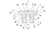
- FIG. 1 is a front view of a rubber stopper for a drug container according to an embodiment of the present invention.
- FIG. 2 is a plan view of the rubber stopper for the drug container shown in FIG.
- FIG. 3 is a bottom view of the rubber stopper for the drug container shown in FIG.
- FIG. 4 is a right side view of the rubber stopper for the drug container shown in FIG.
- FIG. 5 is a cross-sectional view taken along line AA in FIG. 6 is a cross-sectional view taken along line BB in FIG.
- FIG. 7 is a perspective view of the drug container rubber stopper shown in FIG. 1 as viewed obliquely from below.
- FIG. 8 is a perspective view of the drug container rubber stopper shown in FIG. 1 as viewed obliquely from above.
- FIG. 1 is a front view of a rubber stopper for a drug container according to an embodiment of the present invention.
- FIG. 2 is a plan view of the rubber stopper for the drug container shown in FIG
- FIG. 9 is a front view of a rubber stopper for a drug container according to another embodiment of the present invention.
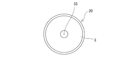
- FIG. 10 is a plan view of the rubber stopper for the drug container shown in FIG.
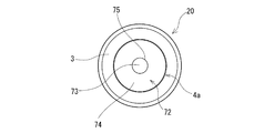
- FIG. 11 is a bottom view of the rubber stopper for the drug container shown in FIG. 12 is a cross-sectional view taken along the line CC of FIG.
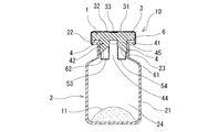
- FIG. 13 is a front view of a medicine container in which the medicine is an embodiment of the present invention.
- FIG. 14 is a plan view of the medicine container with medicine stored in FIG. 15 is a cross-sectional view taken along the line DD of FIG. 16 is a cross-sectional view taken along the line EE of FIG. FIG.
- FIG. 17 is an explanatory diagram for explaining a manufacturing process of the medicine container in which the medicine is stored according to the present invention.
- FIG. 18 is an explanatory diagram for explaining a manufacturing process of the medicine container in which the medicine is stored according to the present invention.
- FIG. 19 is a front view of a drug container set according to an embodiment of the present invention.
- 20 is a front view of a liquid injection needle used in the drug container set shown in FIG. 21 is a cross-sectional view taken along line FF in FIG.
- FIG. 22 is a front view of a drug container set according to another embodiment of the present invention.
- FIG. 23 is an explanatory diagram for explaining the operation of the rubber stopper for a medicine container and the medicine container in which medicine is stored according to the present invention.
- the rubber stopper for a drug container of the present invention will be described with reference to the embodiments shown in the drawings.
- the rubber stopper 1 for a drug container according to the present invention has a cylindrical barrel portion 21 whose lower end is closed and which stores a drug therein, and which extends upward from the upper end of the barrel portion 21 and has an opening formed at the upper end.
- the neck portion 23 is attached to the drug container 2 whose inner diameter is smaller than the inner diameter of the body portion 21 and is substantially constant.
- the drug container rubber stopper 1 includes a main body part 3 and a cylindrical in-box entry part 4 that extends downward from the lower surface of the main body part 3 and can be fitted into the neck part 23 of the drug container 2.
- the main-body part 3 is arrange
- the in-container entry portion 4 has substantially the same shape downward from the outer surface portion 40 that contacts the inner surface of the neck portion 23 of the medicine container 2 and the center portion of the lower surface of the main body portion 3 when the medicine container 2 is mounted.
- An upper inner surface portion that forms an extending columnar gap 45; and inclined surfaces 61 and 62 extending obliquely downward from the lower end of the upper inner surface portion toward the outer surface portion 40 of the in-container entry portion 4, and at least of the outer surface portion 40
- the upper end 48 is in an annular and liquid-tight contact with the inner surface of the neck, and the lower ends of the inclined surfaces 61 and 62 reach or approach the outer surface 40 of the in-container entry portion 4.
- the drug container rubber stopper 1 extends downward from the center of the disk-shaped main body 3 and the lower surface of the main body 3 with an outer diameter smaller than the outer diameter of the main body. And an in-container entry portion 4.
- the main body 3 has a disk shape having a predetermined thickness.
- the lower surface peripheral part 30 of the main-body part 3 comprises the cyclic
- the main body 3 is preferably disk-shaped.
- the main body 3 is not disc-shaped as long as it has a shape that is disposed radially outside the in-container entry portion 4 and has a peripheral edge that comes into contact with the upper surface of the opening when attached to the drug container 2. May be.
- the main body 3 may be a polygonal plate having a peripheral edge disposed radially outside the in-container entry portion 4. Note that the lower surface of the peripheral edge constitutes the lower peripheral edge 30.
- the in-container entry portion 4 has an arcuate outer surface or a cylindrical outer surface, and extends downward in substantially the same outer surface form.
- the lower part (leg part to be described later) of the in-container entry part 4 is smaller in diameter of a virtual circle that can be formed from the outer edge than the upper part and the center part, and can be easily inserted into the medicine container. It is supposed to be.
- the diameter of the in-container entry portion 4 (or the diameter of a virtual circle that can be formed from the outer edge) gradually decreases from the upper end toward the lower end.
- the diameter (or the diameter of a virtual circle that can be formed from the outer edge) of the upper part of the in-container entry part 4 does not substantially change and may extend with the same diameter.
- the outer surface portion 40 of the in-container entry portion 4 is in contact with the inner peripheral surface of the opening 22 of the drug container 2 to form a liquid-tight state.
- the upper part of the in-container entry portion 4 is strongly compressed by the inner peripheral surface of the opening 22 of the medicine container 2.
- At least the upper end 48 of the outer surface 40 is in annular and liquid-tight contact with the inner surface of the neck 23 of the drug container 2. Therefore, the upper end portion 48 of the outer surface portion 40 has a cylindrical shape extending with substantially the same outer diameter.
- the inner diameter extends substantially at the same inner diameter.
- the axial length of the upper end portion 48 is preferably 1.0 to 4.0 mm, and particularly preferably 2.0 to 3.0 mm.
- an elastic material As a constituent material of the rubber plug 1, an elastic material is preferable.
- the elastic material is not particularly limited, and examples thereof include various rubber materials (particularly, vulcanized) such as natural rubber, isoprene rubber, butyl rubber, chloroprene rubber, nitrile-butadiene rubber, styrene-butadiene rubber, and silicone rubber. Can be mentioned.
- diene rubber is preferable from the viewpoint of having elastic properties and capable of ⁇ -ray sterilization, electron beam sterilization, and high-pressure steam sterilization.
- the in-container entry portion 4 is located between the two columnar portions 41 and 42 facing each other and the two columnar portions 41 and 42, and is located at the upper center of the in-container entry portion 4.
- a columnar gap 45 extending in substantially the same shape from the (center) downward is provided.
- the columnar gap 45 preferably extends in the same shape and size as in the illustrated embodiment, but may be slightly larger downward.
- inclined surfaces 61 and 62 extending with a predetermined width in the direction toward the outer surface 40 of the in-container entry portion 4 and obliquely downward, with a part of the columnar gap 45 as a starting end (upper end). Is provided.
- two inclined surfaces 61 and 62 are provided so as to face the central axis X of the columnar gap 45.
- the lower ends of the inclined surfaces 61 and 62 reach or approach the outer surface portion 40 of the in-container entry portion 4.
- the joints between the lower ends of the inclined surfaces 61 and 62 and the outer surface part 40 are integrated, and the joints are chamfered and rounded.
- the upper ends of the inclined surfaces 61 and 62 are located below a predetermined length from the inner upper end of the in-container entry portion 4 (columnar portions 41 and 42). For this reason, the columnar gap 45 maintains the columnar shape until it reaches the upper ends of the inclined surfaces 61 and 62.
- the in-container entry portion 4 (columnar portions 41, 42) has opposing inner surface portions 63, 64 extending upward from the upper ends of the inclined surfaces 61, 62.
- opposed inner surface portions 63 and 64 are formed between the inner upper end of the in-container entry portion 4 (columnar portions 41 and 42) and the upper ends of the inclined surfaces 61 and 62.
- the inner surface portions 63 and 64 are flat inner walls.
- the inner surface portions 63 and 64 may be arcuate.
- the distance between the inner upper end (lower surface) and the upper ends of the inclined surfaces 61 and 62 is preferably 1 to 8 mm, and particularly preferably 3 to 5 mm.
- the distance (W) between the inner surface portions 63 and 64 facing each other, in other words, the width of the columnar gap 45 is preferably 1.6 to 7 mm, and particularly preferably 2.0 to 5.5 mm.
- the inclined surfaces 61 and 62 extend from the upper end (start end) to the lower end (end end) with substantially the same width. .
- the inclined surfaces 61 and 62 may be narrower toward the lower end (end), and may be wider.
- the width of the upper ends of the inclined surfaces 61 and 62 is preferably 1.8 to 5 mm, and particularly preferably 2.5 to 4.0 mm.
- the lower ends of the inclined surfaces 61 and 62 are preferably located at least 0.5 mm above the lower end of the neck portion 23 of the drug container 2 when mounted on the drug container 2.
- the inclination angle of the inclined surfaces 61 and 62 (inclination angle with respect to the central axis of the in-container entry portion 4) is preferably 30 to 60 degrees, and particularly preferably 35 to 45 degrees.
- the width of the inclined surfaces 61 and 62 is preferably 1.5 to 8.0 mm, particularly preferably 2.0 to 6.0 mm.
- the in-container entry portion 4 has leg portions 51, which are provided on both sides of the inclined surfaces 61, 62 and extend downward. 52, 53, 54. Specifically, inclined surfaces 61 and 62 are provided at the center of the columnar portions 41 and 42, and notches 46 and 47 are formed below the inclined surfaces 61 and 62.
- the columnar part 41 has leg parts 51 and 54 on the side part of the notch part 46, and the columnar part 42 has leg parts 52 and 53 on the side part of the notch part 47.
- the inclined surfaces 61 and 62 have both side portions, and the in-container entry portion 4 has the inclined surfaces 61 and 62, respectively.
- the above-mentioned legs 51, 52, 53, 54 that extend downward are provided so as to sandwich the inclined surfaces 61, 62, respectively, and the legs 51, 52, 53, 54 are at least It has the outer surface part 40 extended to the lower end of the inclined surfaces 61 and 62. As shown in FIG. Thereby, when the rubber stopper 1 is attached to the medicine container 2, the lower end of the inclined surface of the rubber stopper can be inserted without being caught in the opening of the medicine container 2.
- the legs 51, 52, 53, 54 extend further downward beyond the lower ends of the inclined surfaces 61, 62.
- the outer surface portion 40 is provided. This makes it easier to attach the rubber stopper to the drug container.
- the leg portions 51, 52, 53, and 54 are contracted at the lower end where the diameter is reduced downward from the lower end of the outer surface portion 40. It has a diameter part. This makes it easier to insert the rubber stopper into the drug container.
- the axial length from the upper end to the lower end of the leg portions 51, 52, 53, 54 of the in-container entry portion 4 is preferably 5 to 10 mm, and particularly preferably 6 to 8 mm.
- the axial length (H) from the upper end to the lower end of the inclined surfaces 61 and 62 of the in-container entry portion 4 is preferably 2 to 6 mm, and particularly preferably 3 to 5 mm.
- the axial length from the lower end of the inclined surfaces 61, 62 to the lower ends of the leg portions 51, 52, 53, 54 is preferably 1 to 5 mm, and particularly preferably 2 to 4 mm.
- the in-container entry portion 4 includes two opposing side gap portions 43 and 44 that communicate with the columnar gap portion 45. ing. Specifically, the two columnar portions 41 and 42 are separated from each other, and side gap portions 43 and 44 are formed therebetween.
- the side gaps 43 and 44 extend from the upper end to the lower end of the in-container entry portion 4.
- the columnar gap 45 also extends from the upper end to the lower end of the in-container entry portion 4. The side gaps 43 and 44 communicate with the columnar gap 45 described above at the upper part thereof.
- the side gaps 43 and 44 and the columnar gap 45 are integrated at the top.
- the widths of the side gaps 43 and 44 are the same as the distance (W) between the inner surfaces 63 and 64 facing each other.
- the side gaps 43 and 44 may be widened at the center and the lower part thereof, or may be narrowed.
- the four leg portions 51, 52, 53, 54 extend downward by a predetermined length as described above, and have fan-shaped bottom portions 51a, 52a, 53a, 54a at the lower ends thereof.
- the leg parts 51, 52, 53, 54 are fan-shaped columnar parts.
- the two side gaps may not extend to the lower end of the in-container entry part 4 but terminate in the vicinity of the lower part of the center part.
- the first leg portion and the second leg portion are connected by the connecting portion, and the third leg portion and the fourth leg portion are connected by the connecting portion.
- a connection part functions as a guidance
- the in-container entry portion has a crescent-shaped bottom portion on the lower surface.
- the rubber stopper 1 for a medicine container of this embodiment includes inclined surface markers 31 and 32 provided on the upper surface portion of the main body 3 above or near the inclined surfaces 61 and 62. Specifically, as shown in FIGS. 1 and 6, the first inclined surface marker 31 is formed at a position directly above the inclined surface 61 and slightly from the center of the main body 3. Similarly, the second inclined surface marker 32 is formed at a position directly above the inclined surface 62 and slightly from the center of the main body 3. By puncturing the liquid injection needle so that the side hole position of the liquid injection needle coincides with the inclined surface markers 31 and 32, the side holes are formed on the inner surface portions (inner wall surfaces) of the upper surfaces of the inclined surfaces 61 and 62. ) 63, 64.
- each of the markers 31 and 32 is formed by a triangular protrusion whose one vertex faces the central direction of the main body 3.
- the marker may be a concave portion, a printed one, and the shape may be an arrow.
- the drug container rubber stopper 1 of this embodiment includes a columnar gap marker 33 provided on the upper surface portion of the main body 3 above the columnar gap 45.
- the columnar gap marker 33 is formed by a circular recess.
- the columnar gap marker 33 may be a protruding portion, and may have a ring shape, a polygonal shape, or the like.
- medical agents containers of this invention is not limited to what was mentioned above.
- the columnar portions 41 and 42 of the in-container entry portion 4 are not provided with the notches 46 and 47 as described above below the inclined surfaces 61 and 62, and the lower ends of the inclined surfaces 61 and 62 are in the in-container entry portion. It may extend to the lower ends of the four columnar portions 41, 42.
- it may have only one side gap.
- the rubber plug 20 for a drug container of this embodiment includes a main body part 3 and a columnar in-container entry part 4 a that extends downward from the lower surface of the main body part 3 and can be fitted into the opening of the drug container 2.
- the in-container entry portion 4a has substantially the same shape as the outer surface portion 40 that contacts the inner surface of the opening of the medicine container 2 and the center upper portion of the in-container entry portion 4a downward when the medicine container 2 is mounted.
- the columnar void 73 extends, the inclined surface 74 extends obliquely downward from the columnar void 73 toward the outer surface 40 of the in-container entry portion 4a, and the inner surface 75 extends upward from the upper end of the inclined surface 74. Yes.
- the lower end of the inclined surface 74 reaches or is close to the outer surface portion 40 of the in-container entry portion 4a.
- the inclined surface is a tapered inclined surface 74 that surrounds the columnar gap 73 in an annular shape and expands in diameter downward.
- the main body 3 has a disk shape having a predetermined thickness. And the lower surface peripheral part 30 of the main-body part 3 comprises the cyclic
- the main body 3 is preferably disk-shaped. However, the main body 3 is arranged in a disk shape as long as it has a shape that is disposed radially outside the in-container entry portion 4a and has a peripheral edge that comes into contact with the upper surface of the opening 22 when mounted on the drug container 2. It does not have to be.
- the main body 3 may be a polygonal plate having a peripheral edge disposed radially outside the in-container entry portion 4a.
- the lower surface of this peripheral part comprises a lower surface peripheral part.
- the outer surface portion 40 of the in-container entry portion 4a is in contact with the inner peripheral surface of the opening 22 of the drug container 2 to form a liquid-tight state.
- the upper part of the in-container entry portion 4 is strongly compressed by the inner peripheral surface of the opening 22 of the medicine container 2.
- the constituent material of the rubber plug 20 those described above are used.
- the in-container entry portion 4a extends downward from the lower surface of the main body portion 3 and has an upper columnar portion 71 having a smaller diameter than the main body portion 3, and extends downward from the upper columnar portion 71 so that the inner surface increases in diameter toward the lower end.
- a lower columnar portion 72 having an inclined surface 74.
- the upper columnar portion 71 is formed in a substantially columnar shape and has a columnar gap 73 therein.
- the columnar gap 73 forms an inner surface 75 that extends upward from the upper end of the inclined surface 74.
- the columnar gap 73 is cylindrical.
- the inner surface part 75 is also cylindrical.
- the columnar gap 73 may be a prismatic shape, an elliptical column shape, or the like. Further, the columnar voids preferably extend in the same shape, but may be slightly larger downward.
- the axial length (height) of the inner surface portion 75 of the upper columnar portion 71 is preferably 1 to 8 mm, particularly 3 to 5 mm. preferable.
- the inner diameter of the columnar gap 73 is preferably 1.6 to 7 mm, and particularly preferably 2.0 to 5.5 mm.
- the lower columnar portion 72 includes a tapered inclined surface 74 that extends downward from the lower end of the columnar gap 73 and expands in diameter toward the lower end.
- the lower end of the tapered inclined surface 74 reaches or is close to the outer surface portion 40 of the in-container entry portion 4a.
- the joint portion between the lower end of the inclined surface 74 and the outer surface portion 40 is integrated, and the joint portion is chamfered and rounded.
- the diameter of the lower columnar portion 72 is slightly reduced downward.
- the axial length (height) of the lower columnar portion 72 in other words, the axial length from the upper end to the lower end of the tapered inclined surface 74 is preferably 3 to 8 mm, and particularly preferably 4 to 6 mm.
- the inclination angle of the inclined surface 74 is preferably 30 to 50 degrees, and particularly preferably 35 to 45 degrees.
- the medicine container 10 with medicines of the present invention includes a medicine container 2 having an opening, the above-described rubber plug 1 for medicine container that is attached to the opening 22 of the medicine container 2 and seals the opening 22, and a medicine container. 2 and the medicine 11 stored in the inside.
- the medicine container 2 has a cylindrical body portion 21 that is closed at the lower end and stores the medicine inside, and a cylindrical neck portion 23 that extends upward from the upper end of the body portion 21 and has an opening at the upper end.
- the inner diameter of the neck 23 is smaller than the inner diameter of the body 21.
- the medicine container 2 has an opening, and the medicine 11 can be stored in the inside 24.
- a rigid or semi-rigid synthetic resin container, a glass container, or the like is used as the drug container.
- the medicine container 2 includes a cylindrical main body (trunk) 21 whose lower end is closed, an opening 22 having a thick flange, and other openings formed between the opening 22 and the main body (trunk) 21.
- a subtotal neck 23 is provided from the part.
- medical agent container 2 is a storage part which accommodates the in-container entrance part 4 of the rubber stopper 1 extended by the same internal diameter.
- the upper inner surface of the neck portion 23 and the upper end portion 48 of the outer surface portion 40 of the rubber plug 1 are in annular and liquid-tight contact.
- the rubber plug 1 the rubber plugs of all the embodiments described above can be used.
- medical agent 11 platinum-type anticancer agent, protein preparations, such as insulin, nitroglycerin, isosorbide nitrate, nicardipine hydrochloride, monoammonium glycyrrhizinate, a protein preparation, an antitumor agent, a vitamin agent ( Multivitamin preparations), various amino acids, antithrombotic agents such as heparin, antibiotics, analgesics, cardiotonic agents, intravenous anesthetics, antiparkinsonian agents, ulcer treatment agents, corticosteroid agents, arrhythmic agents and the like.
- the dosage form of the drug is not particularly limited, and may be any liquid drug, powder drug, lyophilized drug, solid drug, and the like.
- dissolution or dilution the rubber stopper of this invention is effective.
- examples of such drugs include hormone preparations, antibody preparations, and antitumor agents.
- the medicine container 10 with the medicine stored in this embodiment includes a covering member 6 that covers the peripheral edge of the opening 22 and the peripheral edge of the rubber stopper 1 of the medicine container 2 to which the rubber stopper 1 is attached.
- the covering member 6 is preferably formed of aluminum, a heat-shrinkable film, or the like, and is in close contact with the rubber stopper or the drug container body.
- the covering member 6 is provided with openings for exposing the inclined surface markers 31 and 32 and the columnar gap marker 33.
- the covering member 6 may cover the entire upper surface of the rubber plug 1 as long as the puncture needle for confirmation of the inclined surface markers 31 and 32 and liquid injection can be punctured.
- the covering member 6 includes an annular portion and a thin donut board-like upper surface portion, and a lower end portion of the annular portion is a main body portion (body portion) of the medicine container 2.
- the annular lower surface of the opening 22 of 21 is covered.
- the inside may be pressure-reduced.
- the medicine container 10 with medicine stored according to the present invention it is possible to easily store the freeze-dried medicine inside.
- the inside 24 and the outside of the drug container 2 are connected to the side gaps 43 and 44 and the columnar gaps of the rubber plug 1.
- the rubber stopper 1 is temporarily attached to the medicine container 2 so as to communicate with each other via 45.
- the rubber stopper 1 is inserted into the medicine container 2 from above, and the portions where the leg portions 51, 52, 53, 54 and the inclined surfaces 61, 62 are formed are accommodated in the medicine container, and the container entrance portion 4 (columnar portions 41, 42) and the side gaps 43, 44 are exposed from the drug container.
- the drug solution 11a becomes the freeze-drying agent 11 as shown in FIG.
- the rubber plug 1 is pushed in, the upper inner surface of the neck portion 23 and the upper end portion 48 of the outer surface portion 40 of the rubber plug 1 are in close contact with each other in an annular and liquid-tight manner. Is sealed. Further, by encapsulating the opening portions of the rubber stopper 1 and the medicine container 2 with the covering member 6, the medicine container 10 containing the medicine is created.
- the drug container set 30 of the present invention comprises the above-described drug container 10 of the present invention and the liquid injection needle 8 that can be inserted into the rubber stopper 1 of the drug container 10.
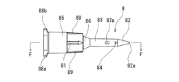
- the liquid injection needle 8 a needle having a closed puncture end 82 a and liquid discharge side holes 87 a and 87 b provided on the side of the distal end is used.
- the liquid injection needle 8 of this embodiment has a puncture portion 82 at the distal end and a hub portion 85 that can be attached to a luer taper nozzle of a medical device at the proximal end. And the puncture part 82 is diameter-reduced to a taper shape toward the front-end
- the liquid injection needle 8 includes a hollow portion 83 that is continuous with the puncture portion 82 and extends to the proximal end side. The hollow portion 83 has a lumen 80 that communicates with the inside of the hub portion 85, and side holes 87a and 87b that communicate the lumen 80 and the outside.
- the liquid injection needle 8 of this embodiment has a hub portion 85 having a diameter larger than the hollow portion 83 and a predetermined length, and a short portion provided between the hub portion 85 and the hollow portion 83. And a tapered portion 86.
- the hollow portion 83 extends a predetermined length from the proximal end of the puncture portion 82 and includes a lumen 80 therein. In this embodiment, the hollow portion 83 extends to the tip of the tapered portion 86.
- side holes 87 a and 87 b that communicate the inside of the liquid injection needle 8, in other words, the lumen 80 and the outside, are provided.
- the puncture part 82 is diameter-reduced in a taper shape toward the front-end
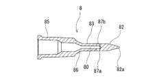
- the liquid injection needle 8 of this embodiment includes a solid tapered puncture portion 82, a hollow portion 83, a taper portion 86, and a hub portion 85 from the distal end side. It has. Further, in the liquid injection needle 8 of this embodiment, the distal end portion of the lumen 80 is reduced in diameter toward the distal end and is terminated without reaching the puncture portion 82.
- the side holes 87 a and 87 b are provided at the tip of the lumen 80 so as to communicate with the lumen 80.
- the puncture portion 82 has a puncture end 82a at the distal end, and is a solid one that increases in diameter toward the proximal end with an acute taper angle (taper expansion angle).
- the length from the tip of the tapered portion 86 (the base end of the hollow portion 83) to the tips of the side holes 87a and 87b is the length of the columnar gap 45 of the rubber plug 1.
- the sum of the thickness of the main body portion 3 and the axial length of the inner surface portions 63 and 64 formed by the columnar gap 45 (in other words, from the upper surface of the main body 3 to the inner wall 63, 64, the distance between the lower ends).
- the side holes 87a and 87b are formed by the columnar gap 45 in a state where the hollow end 83 is inserted into the rubber stopper up to the base end (tip of the tapered portion 86). It is located in the formation part of the inner surface parts 63 and 64. Further, the side holes 87a and 87b face the inner surface parts 63 and 64. For this reason, the liquid discharged from the side holes 87a and 87b reliably contacts the inner surface portions 63 and 64. In the liquid injection needle 8 of this embodiment, two side holes are provided so as to face each other. Note that there may be only one side hole.
- the difference between the distance (W) between the inner surface portions 63 and 64 facing each other and the outer diameter of the side holes 87a and 87b of the liquid injection needle 8 is preferably 0.1 to 3.6 mm. 1.0 to 2.5 mm is preferable. Thereby, the liquid discharged from the side holes 87a and 87b can be made to contact the inner surface parts 63 and 64 more reliably.
- the liquid injection needle 8 preferably has a stopper that regulates the length of insertion into the rubber stopper.
- the tapered portion 86 that connects the proximal end of the hollow portion 83 and the distal end of the hub portion 85 has a diameter that is abruptly expanded following the hollow portion 83, and is connected to the rubber plug 1. It is virtually impossible to insert. In other words.
- the taper part 86 functions as a stopper at the time of insertion.
- the hub portion 85 is a cylindrical portion that extends rearward from the proximal end of the taper 86 and has an inner surface form that can be attached to a luer taper nozzle of a medical device. Specifically, the inside of the hub portion 85 is provided with a 6% taper, so that a normal standard female female connection portion (for example, a nozzle portion of a syringe) having a 6% taper can be connected.
- the standard medical female connection is ISO 594-1: 1986 “Matching joints with 6% (about 3.43 °) taper of syringe barrels, needles and other medical devices-Part 1 : General requirements ”.
- Two ribs 88 a and 88 b provided to face each other are provided on the outer surface of the base end portion of the hub portion 85.
- the ribs 88a and 88b can be used as screwed portions when screwed with screwed portions of other medical devices.
- the liquid injection needle 8 of this embodiment includes a side hole marker 81 provided on the side surface of the liquid injection needle 8 and on the axis of the liquid injection needle passing through the side holes 87a and 87b.
- a side hole marker 81 provided on the outer surface near the tip of the hub portion 85 is provided, and the side holes 87 a and 87 b are located in front of the extension line of the marker 81.
- a front side hole marker 84 is also provided in front of the side holes 87a and 87b.
- a projecting portion 89 extending in the axial direction is provided on the outer surface of the hub portion 85. The protruding portion 89 can be used as a grip portion of the liquid injection needle 8 and facilitates screwing with another medical device of the hub portion 85.
- Examples of the material for forming the liquid injection needle 8 include polypropylene, polyethylene, polystyrene, polyamide, polycarbonate, polyvinyl chloride, poly- (4-methylpentene-1), acrylic resin, acrylonitrile-butadiene-styrene copolymer, Polyester such as polyethylene terephthalate, cyclic olefin resin, polyether ether ketone, polybutylene terephthalate, polyacetal, modified polyphenylene ether, polyester resin, fluorine resin, polysulfone, polyetherimide, polyethersulfone, polyetherketone, polyether Thermoplastic resins such as lactones and liquid crystalline polyesters, or epoxy resins, unsaturated polyester resins, phenol resins, urea resins, melamine resins, polyurethane resins Such as a thermosetting resin.
- Polyester such as polyethylene terephthalate, cyclic olefin resin, polyether ether ketone, poly
- the drug container set 50 of the present invention includes the above-described drug container 10 of the present invention, a liquid injection needle 8 that can be inserted into the rubber stopper 1 of the drug container 10, and a prefilled syringe 9. .
- a prefilled syringe 9 is added to the above-described drug container set 30.
- the medicine container 10 and the liquid injection needle 8 are as described above.
- the prefilled syringe 9 a known one is used.
- the prefilled syringe 9 used in this embodiment includes an outer cylinder 90 having a cylindrical outer cylinder main body portion, a luer taper nozzle 91 provided at the distal end portion of the outer cylinder main body portion and having a distal end opening, and an outer cylinder 90.
- a gasket 94 slidably housed therein, a medical liquid 97 filled in the outer cylinder 90, a sealing member 93 for sealing the distal end opening, and a base end of the gasket 94.
- a possible pusher 92 is provided.
- a chemical solution capable of dissolving or diluting the drug in the drug container for example, water for injection, physiological saline, and aqueous glucose solution is preferable.
- the drug may contain a drug (for example, vitamin, mineral, cyclosporine, benzodiazepine drug, sodium chloride injection, antibiotic, protein preparation) and can be diluted or dissolved.
- the prefilled syringe 9 includes a sealing member 93 (specifically, a removable cap) attached to the luer taper nozzle 91 in order to seal the distal end opening of the outer cylinder 90.
- the sealing member may be a peelable film.
- the outer cylinder 90 is a cylindrical body made of a transparent or semi-transparent material and, if necessary, a material having low oxygen permeability and water vapor permeability.
- the outer cylinder 90 includes a main body portion, the above-described luer taper nozzle 91, a collar 95 that encloses the luer taper nozzle 91 and has an internal thread portion on the inner surface, and a flange 96 provided at the rear end portion.
- the luer taper nozzle 91 is a normal medical female connection part.
- the standard medical female connection is ISO 594-1: 1986 “Matching joints with 6% (about 3.43 °) taper of syringe barrels, needles and other medical devices-Part 1 : General requirements ”.
- the gasket 94 includes a main body portion extending at substantially the same outer diameter and a plurality of annular ribs (two in this embodiment) provided on the main body portion. Slide while in close contact.
- a pusher 92 is connected to the gasket 94 at its rear end. The pusher 92 may be attached at the time of use.
- the pusher 92 includes a pressing portion 98 at the rear end.
- the liquid injection needle 8 is attached to the luer taper nozzle 91 of the syringe 9 filled with the medical liquid 97 using the hub portion 85.
- the liquid injection needle 8 to which the syringe 9 is connected is punctured into the rubber stopper 1 of the medicine container 10 containing medicine.
- it is performed while confirming that the side hole marker 84 of the liquid injection needle 8 coincides with the inclined surface markers 31 and 32 formed on the upper surface of the main body 3 of the rubber plug 1.
- the side holes 87a and 87b of the liquid injection needle 8 are positioned in the columnar gap 45 as shown in FIG.
- the inner surfaces 63 and 64 located on the upper surfaces of the inclined surfaces 61 and 62 face each other.
- the rubber stopper for a drug container of the present invention is as follows.
- the neck portion has a cylindrical barrel portion that is closed at the lower end and stores the medicine therein, and a cylindrical neck portion that extends upward from the upper end of the barrel portion and that has an opening at the upper end.
- the drug container rubber plug is attached to a drug container having an inner diameter smaller than the inner diameter of the barrel part and substantially constant, the drug container rubber plug comprising: a main body part; A cylindrical in-vessel entry portion that extends downward from the lower surface and can be fitted into the neck portion of the drug container, and the main body portion is disposed radially outside the in-container entry portion, and the drug container A peripheral portion that comes into contact with the upper surface of the opening when attached to the container, and the in-container entry portion includes an outer surface portion that contacts an inner surface of the neck of the drug container when attached to the drug container.
- the main body extends downwardly from the center of the lower surface in substantially the same shape.
- An upper inner surface portion that forms a columnar void portion, and an inclined surface extending obliquely downward from the lower end of the upper inner surface portion toward the outer surface portion of the in-container entry portion, and at least the upper end portion of the outer surface portion is A rubber stopper for a medicine container, which is in annular and liquid-tight contact with the inner surface of the neck, and the lower end of the inclined surface reaches or is close to the outer surface of the entry portion in the container.
- the medical liquid is discharged in a state where the side hole of the hollow needle is located in the columnar space, so that the discharged liquid is continuous with the inner surface of the columnar space and the lower end. After flowing along an inclined surface that reaches or is close to the outer surface of the in-container entry portion, it flows downward along the inner surface of the drug container.
- the above embodiment may be as follows.
- the inclined surface has both side portions, the in-container entry portion has a downwardly extending leg portion provided on the both side portions of the inclined surface, and the leg portion is at least of the inclined surface.
- the rubber plug for a medicine container includes the inclined surface marker provided on the upper surface of the main body portion above or near the inclined surface, according to any one of (1) to (7). Rubber stoppers for drug containers.
- the rubber plug for a drug container according to (1) wherein the inclined surface is a tapered inclined surface that surrounds the columnar space in an annular shape and expands in diameter downward.
- the medicine container in which the medicine is stored according to the present invention is as follows. (12) The medicine container, the rubber stopper for the medicine container according to any one of (1) to (11), which is attached to the medicine container and seals the opening, and is housed in the medicine container. A medicine container with a medicine.
- the medicine container in which the medicine is stored includes a covering member that covers a peripheral edge portion of the opening and a peripheral edge portion of the rubber stopper of the medicine container to which the rubber stopper is attached. Medicine container with medicine.
- medical agent container set of this invention is the following.
- a medicine container set comprising the medicine container with the medicine (12) or (13) and a liquid injection needle that can be pierced through the rubber stopper of the medicine container with the medicine,
- the injection needle has a closed puncture end and a liquid discharge side hole provided on the side of the distal end portion.
- the above embodiment may be as follows.
- Container set 17.
Abstract
Description
下端が閉塞し、内部に薬剤を収納する筒状の胴部と、前記胴部の上端から上方に延び、上端に開口部が形成された筒状の首部とを有し、前記首部の内径が前記胴部の内径より小径であり、かつ、ほぼ一定である薬剤容器に装着される薬剤容器用ゴム栓であって、前記薬剤容器用ゴム栓は、本体部と、前記本体部の下面より、下方に延び、前記薬剤容器の前記首部に嵌入可能な筒状の容器内進入部とを備え、前記本体部は、前記容器内進入部よりも径方向外側に配置され、前記薬剤容器への装着時において、前記開口部の上面と当接する周縁部を有し、前記容器内進入部は、前記薬剤容器への装着時において、前記薬剤容器の前記首部の内面に接触する外面部と、前記本体部の前記下面の中央部から下方に向かってほぼ同一形状にて延びる柱状空隙部を形成する上部内面部と、前記上部内面部の下端より前記容器内進入部の外面部方向かつ斜め下方に延びる傾斜面とを有し、上記外面部の少なくとも上端部は、前記首部の内面と環状かつ液密に接触しており、前記傾斜面の下端は、前記容器内進入部の外面部に到達もしくは近接している薬剤容器用ゴム栓。 What achieves the above object is as follows.
The lower end is closed, and has a cylindrical body part for containing the medicine therein, and a cylindrical neck part extending upward from the upper end of the body part and having an opening formed at the upper end, and the inner diameter of the neck part is A rubber plug for a medicine container that is attached to a medicine container that is smaller in diameter than the inner diameter of the body part and is substantially constant, and the rubber stopper for the medicine container includes a main body part and a lower surface of the main body part, A cylindrical container entry portion that extends downward and can be fitted into the neck portion of the drug container, and the main body portion is disposed radially outside the container entry portion, and is attached to the drug container. A peripheral portion that contacts the upper surface of the opening, and the in-container entry portion includes an outer surface portion that contacts an inner surface of the neck portion of the drug container, and the main body when mounted on the drug container Columnar shape extending in substantially the same shape downward from the center of the lower surface of the part An upper inner surface portion that forms a gap portion, and an inclined surface that extends obliquely downward from the lower end of the upper inner surface portion toward the outer surface portion of the in-container entry portion, and at least the upper end portion of the outer surface portion is formed on the neck portion. A rubber stopper for a medicine container, which is in annular and liquid-tight contact with an inner surface, and a lower end of the inclined surface reaches or is close to an outer surface portion of the in-container entry portion.
前記薬剤容器と、前記薬剤容器に装着され、前記開口部を封止する上記の薬剤容器用ゴム栓と、前記薬剤容器内に収納された薬剤とを備える薬剤収納済薬剤容器。 Moreover, what achieves the said objective is as follows.
A medicine container in which a medicine is stored, comprising the medicine container, the rubber stopper for the medicine container attached to the medicine container and sealing the opening, and the medicine stored in the medicine container.
上記の薬剤収納済薬剤容器と、前記薬剤収納済薬剤容器の前記ゴム栓に刺通可能な液体注入用針とからなる薬剤容器セットであって、前記液体注入用針は、閉塞した穿刺端と先端部側部に設けられた液体排出用の側孔を有している薬剤容器セット。 Moreover, what achieves the said objective is as follows.
A drug container set comprising the above-described drug-contained drug container and a liquid injection needle that can be pierced through the rubber stopper of the drug-contained drug container, wherein the liquid injection needle has a closed puncture end, A drug container set having a liquid discharge side hole provided on the side of the tip.
本発明の薬剤容器用ゴム栓1は、下端が閉塞し、内部に薬剤を収納する筒状の胴部21と、胴部21の上端から上方に延び、上端に開口部が形成された筒状の首部23とを有し、首部23の内径が胴部21の内径より小径であり、かつ、ほぼ一定である薬剤容器2に装着されるものである。
そして、薬剤容器用ゴム栓1は、本体部3と、本体部3の下面より、下方に延び、薬剤容器2の首部23に嵌入可能な筒状の容器内進入部4とを備える。
そして、本体部3は、容器内進入部4よりも径方向外側に配置され、薬剤容器2への装着時において、開口部の上面と当接する周縁部を有する。 The rubber stopper for a drug container of the present invention will be described with reference to the embodiments shown in the drawings.
The rubber stopper 1 for a drug container according to the present invention has a
The drug
And the main-
この実施例では、本体部3は、所定の厚さを有する円盤状のものとなっている。そして、本体部3の下面周縁部30は、後述する薬剤容器2の開口部22の上面に接触する環状接触部を構成している。本体部3は、円盤状であることが好ましい。しかし、本体部3は、容器内進入部4よりも径方向外側に配置され、薬剤容器2への装着時において、開口部の上面と当接する周縁部を有する形状であれば、円盤状でなくてもよい。例えば、本体部3は、容器内進入部4よりも径方向外側に配置された周縁部を有する多角形の板状でもよい。なお、この周縁部の下面が、下面周縁部30を構成する。 As shown in FIGS. 1 to 8, the drug
In this embodiment, the
そして、各柱状部41,42には、柱状空隙部45の一部を始端(上端)として、容器内進入部4の外面部40方向かつ斜め下方に、所定幅にて延びる傾斜面61,62が設けられている。傾斜面61,62は、図6に示すように、柱状空隙部45の中心軸Xに対して向かい合うように2つ設けられている。そして、傾斜面61,62の下端は、容器内進入部4の外面部40に到達もしくは近接している。この実施例では、図6に示すように、傾斜面61,62の下端と外面部40との接合部は、一体化するとともに、接合部は、面取りされ丸みを帯びた形状となっている。 In the
In each of the
また、向かい合う内面部63,64間の距離(W)、言い換えれば、柱状空隙部45の幅は、1.6~7mmであることが好ましく、特に、2.0~5.5mmが好ましい。 Then, as shown in FIG. 6, the axial length (L) from the upper end to the lower end of the
The distance (W) between the
特に、傾斜面61,62の下端は、薬剤容器2への装着時において、薬剤容器2の首部23の下端より、0.5mm以上上部に位置するものであることが好ましい。また、傾斜面61,62の傾斜角度(容器内進入部4の中心軸に対する傾斜角度)は、30~60度であることが好ましく、特に、35~45度であることが好ましい。また、傾斜面61,62の幅は、1.5~8.0mmであることが好ましく、特に、2.0~6.0mmが好ましい。 In the drug
In particular, the lower ends of the
なお、2つの側部空隙部は、容器内進入部4の下端まで延びず、中央部下部付近にて終端するものであってもよい。この場合、第1の脚部と第2の脚部とが連結部により連結され、第3の脚部と第4の脚部とが連結部により連結されたものとなる。そして、連結部は、脚部と同様に、ゴム栓を薬剤容器に装着する際の誘導部として機能する。この実施例のゴム栓では、容器内進入部は、下面に三日月状の底面部を有するものとなる。 Further, the four
It should be noted that the two side gaps may not extend to the lower end of the in-
また、上述した実施例のような2つの側部空隙部43,44を有するのではなく、1つのみの側部空隙部を有するものであってもよい。そして、側部空隙部ではなくなる部位には、傾斜面、その上方に位置する内壁面を設けることが好ましい。 And the rubber stopper for chemical | medical agents containers of this invention is not limited to what was mentioned above. For example, the
Further, instead of having the two
この実施例の薬剤容器用ゴム栓20は、本体部3と、本体部3の下面より、下方に延び、薬剤容器2の開口部に嵌入可能な柱状の容器内進入部4aとを備える。容器内進入部4aは、薬剤容器2への装着時において、薬剤容器2の開口部の内面に接触する外面部40と、容器内進入部4aの中央上部から下方に向かってほぼ同一形状にて延びる柱状空隙部73と、柱状空隙部73より、容器内進入部4aの外面部40方向かつ斜め下方に延びる傾斜面74と、傾斜面74の上端より上方に延びる内面部75とを有している。傾斜面74の下端は、容器内進入部4aの外面部40に到達もしくは近接している。そして、この実施例のゴム栓20では、傾斜面は、柱状空隙部73を環状に取り囲みかつ下方に向かって拡径するテーパー状傾斜面74となっている。 Next, the drug
The
容器内進入部4aの外面部40は、薬剤容器2の開口部22の内周面と接触し、液密状態を形成する。なお、容器内進入部4の上部は、薬剤容器2の開口部22の内周面により強く圧縮される。ゴム栓20の構成材料としては、上述したものが使用される。 The
The
上部柱状部71は、ほぼ円柱状に形成されており、内部に柱状空隙部73を有している。そして、この柱状空隙部73により、傾斜面74の上端より上方に延びる内面部75が形成されている。この実施例では、柱状空隙部73は、円柱状のものとなっている。このため、内面部75も円筒状のものとなっている。なお、柱状空隙部73は、角柱状、楕円柱状などであってもよい。また、柱状空隙部は、同じ形状にて延びるものが好ましいが、下方に向かって若干大きくなるものであってもよい。 The in-
The
本発明の薬剤収納済薬剤容器10は、開口部を有する薬剤容器2と、薬剤容器2の開口部22に装着され、開口部22を封止する上述の薬剤容器用ゴム栓1と、薬剤容器2内に収納された薬剤11とを備える。 Next, the
The
薬剤11としては、特に制限されるものではないが、例えば、白金系抗癌剤、インスリン等のタンパク質製剤、ニトログリセリン、硝酸イソソルビド、塩酸ニカルジピン、グリチルリチン酸モノアンモニウム、タンパク製剤、抗腫瘍剤、ビタミン剤(総合ビタミン剤)、各種アミノ酸、ヘパリンのような抗血栓剤、抗生物質、鎮痛剤、強心剤、静注麻酔剤、抗パーキンソン剤、潰瘍治療剤、副腎皮質ホルモン剤、不整脈用剤等が挙げられる。 As the
Although it does not restrict | limit especially as the chemical |
本発明の薬剤容器セット30は、上述した本発明の薬剤収納済薬剤容器10と、薬剤収納済薬剤容器10のゴム栓1に刺通可能な液体注入用針8とからなる。
液体注入用針8としては、閉塞した穿刺端82aと先端部側部に設けられた液体排出用の側孔87a,87bを有するものが用いられている。 Next, the drug container set 30 of the present invention shown in FIGS. 19 to 21 will be described.
The drug container set 30 of the present invention comprises the above-described
As the
本発明の薬剤容器セット50は、上述した本発明の薬剤収納済薬剤容器10と、薬剤収納済薬剤容器10のゴム栓1に刺通可能な液体注入用針8と、プレフィルドシリンジ9とからなる。上述した薬剤容器セット30に、プレフィルドシリンジ9を付加したものである。 Next, the drug container set 50 of the present invention shown in FIG. 22 will be described.
The drug container set 50 of the present invention includes the above-described
プレフィルドシリンジ9としては、公知のものが使用される。この実施例にて用いるプレフィルドシリンジ9は、筒状の外筒本体部と、外筒本体部の先端部に設けられ、先端開口を有するルアーテーパーノズル91とを有する外筒90と、外筒90内に摺動可能に収納されたガスケット94と、外筒90内に充填された医療用液体97と、先端開口を封止する封止部材93と、ガスケット94の基端に取り付けられたもしくは取付可能な押子92を備えている。 The
As the
図23に示すように、液体注入用針8を内部に医療用液体97が充填されたシリンジ9のルアーテーパーノズル91にハブ部85を用いて装着する。シリンジ9が接続された液体注入用針8を図23に示すように、薬剤収納済薬剤容器10のゴム栓1に穿刺する。穿刺時には、液体注入用針8の側孔マーカー84が、ゴム栓1の本体部3の上面に形成されている傾斜面マーカー31,32に一致することを確認しながら行う。このように、シリンジ9が接続された液体注入用針8を穿刺することにより、図23に示すように、液体注入用針8の側孔87a,87bが、柱状空隙部45内に位置するともに、傾斜面61,62の上部に位置する内面部63,64と向かい合うものとなる。 Next, the operation of the rubber stopper for a medicine container, the medicine container in which medicine is stored and the medicine container set of the present invention will be described with reference to FIG.
As shown in FIG. 23, the
(1) 下端が閉塞し、内部に薬剤を収納する筒状の胴部と、前記胴部の上端から上方に延び、上端に開口部が形成された筒状の首部とを有し、前記首部の内径が前記胴部の内径より小径であり、かつ、ほぼ一定である薬剤容器に装着される薬剤容器用ゴム栓であって、前記薬剤容器用ゴム栓は、本体部と、前記本体部の下面より、下方に延び、前記薬剤容器の前記首部に嵌入可能な筒状の容器内進入部とを備え、前記本体部は、前記容器内進入部よりも径方向外側に配置され、前記薬剤容器への装着時において、前記開口部の上面と当接する周縁部を有し、前記容器内進入部は、前記薬剤容器への装着時において、前記薬剤容器の前記首部の内面に接触する外面部と、前記本体部の前記下面の中央部から下方に向かってほぼ同一形状にて延びる柱状空隙部を形成する上部内面部と、前記上部内面部の下端より前記容器内進入部の外面部方向かつ斜め下方に延びる傾斜面とを有し、上記外面部の少なくとも上端部は、前記首部の内面と環状かつ液密に接触しており、前記傾斜面の下端は、前記容器内進入部の外面部に到達もしくは近接している薬剤容器用ゴム栓。 The rubber stopper for a drug container of the present invention is as follows.
(1) The neck portion has a cylindrical barrel portion that is closed at the lower end and stores the medicine therein, and a cylindrical neck portion that extends upward from the upper end of the barrel portion and that has an opening at the upper end. The drug container rubber plug is attached to a drug container having an inner diameter smaller than the inner diameter of the barrel part and substantially constant, the drug container rubber plug comprising: a main body part; A cylindrical in-vessel entry portion that extends downward from the lower surface and can be fitted into the neck portion of the drug container, and the main body portion is disposed radially outside the in-container entry portion, and the drug container A peripheral portion that comes into contact with the upper surface of the opening when attached to the container, and the in-container entry portion includes an outer surface portion that contacts an inner surface of the neck of the drug container when attached to the drug container. The main body extends downwardly from the center of the lower surface in substantially the same shape. An upper inner surface portion that forms a columnar void portion, and an inclined surface extending obliquely downward from the lower end of the upper inner surface portion toward the outer surface portion of the in-container entry portion, and at least the upper end portion of the outer surface portion is A rubber stopper for a medicine container, which is in annular and liquid-tight contact with the inner surface of the neck, and the lower end of the inclined surface reaches or is close to the outer surface of the entry portion in the container.
(2) 前記傾斜面は、前記柱状空隙部の中心軸に対して向かい合うように2つ設けられている上記(1)に記載の薬剤容器用ゴム栓。
(3) 前記容器内進入部は、上端部より下方に、前記柱状空隙部と連通する側部空隙部を備えている上記(1)または(2)に記載の薬剤容器用ゴム栓。
(4) 前記側部空隙部は、前記柱状空隙部を挟んで向かい合うように2つ設けられている上記(3)に記載の薬剤容器用ゴム栓。
(5) 前記傾斜面は両側部を有し、前記容器内進入部は、前記傾斜面の前記両側部に設けられた下方に延びる脚部を有し、前記脚部は、少なくとも前記傾斜面の下端まで延びる前記外面部を有する上記(1)ないし(4)のいずれかに記載の薬剤容器用ゴム栓。
(6) 前記脚部は、前記傾斜面の下端より下方まで延びる前記外面部を有する上記(5)に記載の薬剤容器用ゴム栓。
(7) 前記脚部は、前記外面部の下端から下方に向かって縮径する下端縮径部を有する上記(6)に記載の薬剤容器用ゴム栓。
(8) 前記薬剤容器用ゴム栓は、前記傾斜面の上方もしくはその付近となる前記本体部の上面に設けられた傾斜面マーカーを備えている上記(1)ないし(7)のいずれかに記載の薬剤容器用ゴム栓。
(9) 前記傾斜面は、前記柱状空隙部を環状に取り囲みかつ下方に向かって拡径するテーパー状傾斜面である上記(1)に記載の薬剤容器用ゴム栓。
(10) 前記薬剤容器用ゴム栓は、前記柱状空隙部の上方となる前記本体部の上面に設けられた柱状空隙部マーカーを備えている上記(1)ないし(9)のいずれかに記載の薬剤容器用ゴム栓。
(11) 前記本体部は、円盤状である上記(1)ないし(10)のいずれかに記載の薬剤容器用ゴム栓。 Further, the above embodiment may be as follows.
(2) The drug container rubber stopper according to (1), wherein two inclined surfaces are provided to face the central axis of the columnar void.
(3) The rubber stopper for a drug container according to (1) or (2), wherein the in-container entry portion includes a side space portion communicating with the columnar space portion below the upper end portion.
(4) The rubber stopper for a drug container according to (3), wherein two side gaps are provided so as to face each other across the columnar gap.
(5) The inclined surface has both side portions, the in-container entry portion has a downwardly extending leg portion provided on the both side portions of the inclined surface, and the leg portion is at least of the inclined surface. The rubber stopper for a medicine container according to any one of the above (1) to (4), which has the outer surface portion extending to the lower end.
(6) The rubber stopper for a drug container according to (5), wherein the leg portion includes the outer surface portion extending downward from a lower end of the inclined surface.
(7) The rubber stopper for a medicine container according to (6), wherein the leg portion has a lower-end diameter-reducing portion that is reduced in diameter downward from a lower end of the outer surface portion.
(8) The rubber plug for a medicine container includes the inclined surface marker provided on the upper surface of the main body portion above or near the inclined surface, according to any one of (1) to (7). Rubber stoppers for drug containers.
(9) The rubber plug for a drug container according to (1), wherein the inclined surface is a tapered inclined surface that surrounds the columnar space in an annular shape and expands in diameter downward.
(10) The rubber plug for a drug container according to any one of (1) to (9), further including a columnar void portion marker provided on an upper surface of the main body portion above the columnar void portion. Rubber stopper for drug containers.
(11) The rubber plug for a drug container according to any one of (1) to (10), wherein the main body has a disk shape.
(12) 前記薬剤容器と、前記薬剤容器に装着され、前記開口部を封止する上記(1)ないし(11)のいずれかに記載の薬剤容器用ゴム栓と、前記薬剤容器内に収納された薬剤とを備える薬剤収納済薬剤容器。 Moreover, the medicine container in which the medicine is stored according to the present invention is as follows.
(12) The medicine container, the rubber stopper for the medicine container according to any one of (1) to (11), which is attached to the medicine container and seals the opening, and is housed in the medicine container. A medicine container with a medicine.
(13) 前記薬剤収納済薬剤容器は、前記ゴム栓が装着された前記薬剤容器の前記開口部の周縁部および前記ゴム栓の周縁部を被覆する被覆部材を備えている上記(12)に記載の薬剤収納済薬剤容器。 Further, the above embodiment may be as follows.
(13) The medicine container in which the medicine is stored includes a covering member that covers a peripheral edge portion of the opening and a peripheral edge portion of the rubber stopper of the medicine container to which the rubber stopper is attached. Medicine container with medicine.
(14) 上記(12)または(13)の薬剤収納済薬剤容器と、前記薬剤収納済薬剤容器の前記ゴム栓に刺通可能な液体注入用針とからなる薬剤容器セットであって、前記液体注入用針は、閉塞した穿刺端と先端部側部に設けられた液体排出用の側孔を有している薬剤容器セット。 Moreover, the chemical | medical agent container set of this invention is the following.
(14) A medicine container set comprising the medicine container with the medicine (12) or (13) and a liquid injection needle that can be pierced through the rubber stopper of the medicine container with the medicine, The injection needle has a closed puncture end and a liquid discharge side hole provided on the side of the distal end portion.
(15) 前記液体注入用針は、向かい合うように2つの側孔を有している上記(14)に記載の薬剤容器セット。
(16) 前記液体注入用針は、前記液体注入用針の側面かつ前記側孔を通る前記液体注入用針の軸線上に設けられた側孔マーカーを備えている上記(15)に記載の薬剤容器セット。
(17) 前記薬剤容器セットは、前記液体注入針に接続可能かつ医療用液体が充填されたプレフィルドシリンジを備えている上記(14)ないし(16)のいずれかに記載の薬剤容器セット。 Further, the above embodiment may be as follows.
(15) The drug container set according to (14), wherein the liquid injection needle has two side holes so as to face each other.
(16) The drug according to (15), wherein the liquid injection needle includes a side hole marker provided on a side surface of the liquid injection needle and on an axis of the liquid injection needle passing through the side hole. Container set.
(17) The drug container set according to any one of (14) to (16), wherein the drug container set includes a prefilled syringe that can be connected to the liquid injection needle and is filled with a medical liquid.
Claims (17)
- 下端が閉塞し、内部に薬剤を収納する筒状の胴部と、前記胴部の上端から上方に延び、上端に開口部が形成された筒状の首部とを有し、前記首部の内径が前記胴部の内径より小径であり、かつ、ほぼ一定である薬剤容器に装着される薬剤容器用ゴム栓であって、
前記薬剤容器用ゴム栓は、本体部と、前記本体部の下面より、下方に延び、前記薬剤容器の前記首部に嵌入可能な筒状の容器内進入部とを備え、
前記本体部は、前記容器内進入部よりも径方向外側に配置され、前記薬剤容器への装着時において、前記開口部の上面と当接する周縁部を有し、
前記容器内進入部は、前記薬剤容器への装着時において、前記薬剤容器の前記首部の内面に接触する外面部と、前記本体部の前記下面の中央部から下方に向かってほぼ同一形状にて延びる柱状空隙部を形成する上部内面部と、前記上部内面部の下端より前記容器内進入部の外面部方向かつ斜め下方に延びる傾斜面とを有し、上記外面部の少なくとも上端部は、前記首部の内面と環状かつ液密に接触しており、前記傾斜面の下端は、前記容器内進入部の外面部に到達もしくは近接していることを特徴とする薬剤容器用ゴム栓。 The lower end is closed, and has a cylindrical body part for containing the medicine therein, and a cylindrical neck part extending upward from the upper end of the body part and having an opening formed at the upper end, and the inner diameter of the neck part is A rubber plug for a drug container that is attached to a drug container that is smaller in diameter than the inner diameter of the body and is substantially constant,
The rubber stopper for the drug container includes a main body part, and a cylindrical in-box entry part that extends downward from the lower surface of the main body part and can be fitted into the neck part of the drug container,
The main body portion is disposed on the radially outer side than the in-container entry portion, and has a peripheral edge portion that comes into contact with the upper surface of the opening when attached to the drug container,
The in-container entry portion has substantially the same shape from the center of the lower surface of the main body to the bottom when contacting the inner surface of the neck portion of the drug container and when attached to the drug container. An upper inner surface portion that forms an extending columnar void, and an inclined surface extending obliquely downward from the lower end of the upper inner surface portion toward the outer surface portion of the in-container entry portion, and at least the upper end portion of the outer surface portion is A rubber stopper for a medicine container, which is in annular and liquid-tight contact with an inner surface of a neck portion, and a lower end of the inclined surface reaches or is close to an outer surface portion of the entry portion in the container. - 前記傾斜面は、前記柱状空隙部の中心軸に対して向かい合うように2つ設けられている請求項1に記載の薬剤容器用ゴム栓。 2. The rubber stopper for a drug container according to claim 1, wherein two inclined surfaces are provided so as to face the central axis of the columnar gap.
- 前記容器内進入部は、上端部より下方に、前記柱状空隙部と連通する側部空隙部を備えている請求項1または2に記載の薬剤容器用ゴム栓。 The drug container rubber stopper according to claim 1, wherein the in-container entry portion includes a side gap portion communicating with the columnar gap portion below the upper end portion.
- 前記側部空隙部は、前記柱状空隙部を挟んで向かい合うように2つ設けられている請求項3に記載の薬剤容器用ゴム栓。 The said side part space | gap part is a rubber stopper for a chemical | medical agent container of Claim 3 provided so that it may oppose on both sides of the said columnar space | gap part.
- 前記傾斜面は両側部を有し、前記容器内進入部は、前記傾斜面の前記両側部に設けられた下方に延びる脚部を有し、前記脚部は、少なくとも前記傾斜面の下端まで延びる前記外面部を有する請求項1ないし4のいずれかに記載の薬剤容器用ゴム栓。 The inclined surface has both side portions, the in-container entry portion has a leg portion that extends downward on both side portions of the inclined surface, and the leg portion extends at least to the lower end of the inclined surface. The rubber stopper for a drug container according to any one of claims 1 to 4, comprising the outer surface portion.
- 前記脚部は、前記傾斜面の下端より下方まで延びる前記外面部を有する請求項5に記載の薬剤容器用ゴム栓。 The said leg part is a rubber stopper for chemical | medical agents containers of Claim 5 which has the said outer surface part extended below from the lower end of the said inclined surface.
- 前記脚部は、前記外面部の下端から下方に向かって縮径する下端縮径部を有する請求項6に記載の薬剤容器用ゴム栓。 The rubber stopper for a drug container according to claim 6, wherein the leg portion has a lower diameter-reduced portion that is diameter-reduced downward from a lower end of the outer surface portion.
- 前記薬剤容器用ゴム栓は、前記傾斜面の上方もしくはその付近となる前記本体部の上面に設けられた傾斜面マーカーを備えている請求項1ないし7のいずれかに記載の薬剤容器用ゴム栓。 The rubber plug for a medicine container according to any one of claims 1 to 7, wherein the rubber stopper for the medicine container includes an inclined surface marker provided on an upper surface of the main body above or near the inclined surface. .
- 前記傾斜面は、前記柱状空隙部を環状に取り囲みかつ下方に向かって拡径するテーパー状傾斜面である請求項1に記載の薬剤容器用ゴム栓。 2. The rubber stopper for a drug container according to claim 1, wherein the inclined surface is a tapered inclined surface that surrounds the columnar gap in an annular shape and expands in diameter downward.
- 前記薬剤容器用ゴム栓は、前記柱状空隙部の上方となる前記本体部の上面に設けられた柱状空隙部マーカーを備えている請求項1ないし9のいずれかに記載の薬剤容器用ゴム栓。 The drug container rubber stopper according to any one of claims 1 to 9, wherein the drug container rubber stopper includes a columnar void portion marker provided on an upper surface of the main body portion above the columnar void portion.
- 前記本体部は、円盤状である請求項1ないし10のいずれかに記載の薬剤容器用ゴム栓。 The rubber plug for a medicine container according to any one of claims 1 to 10, wherein the main body has a disk shape.
- 前記薬剤容器と、前記薬剤容器に装着され、前記開口部を封止する請求項1ないし11のいずれかに記載の薬剤容器用ゴム栓と、前記薬剤容器内に収納された薬剤とを備えることを特徴とする薬剤収納済薬剤容器。 The medicine container, the medicine container rubber stopper according to any one of claims 1 to 11, which is attached to the medicine container and seals the opening, and the medicine stored in the medicine container. A medicine container containing a medicine.
- 前記薬剤収納済薬剤容器は、前記ゴム栓が装着された前記薬剤容器の前記開口部の周縁部および前記ゴム栓の周縁部を被覆する被覆部材を備えている請求項12に記載の薬剤収納済薬剤容器。 13. The drug-accommodated product according to claim 12, wherein the drug-accommodated drug container includes a covering member that covers a peripheral edge of the opening and a peripheral edge of the rubber stopper of the drug container to which the rubber stopper is attached. Drug container.
- 請求項12または13の薬剤収納済薬剤容器と、前記薬剤収納済薬剤容器の前記ゴム栓に刺通可能な液体注入用針とからなる薬剤容器セットであって、前記液体注入用針は、閉塞した穿刺端と先端部側部に設けられた液体排出用の側孔を有していることを特徴とする薬剤容器セット。 A drug container set comprising the drug container with medicine stored in claim 12 or 13 and a liquid injection needle that can be pierced through the rubber stopper of the drug container with medicine stored therein. A drug container set comprising a puncture end and a side hole for discharging liquid provided in a side portion of the distal end.
- 前記液体注入用針は、向かい合うように2つの側孔を有している請求項14に記載の薬剤容器セット。 The drug container set according to claim 14, wherein the liquid injection needle has two side holes so as to face each other.
- 前記液体注入用針は、前記液体注入用針の側面かつ前記側孔を通る前記液体注入用針の軸線上に設けられた側孔マーカーを備えている請求項15に記載の薬剤容器セット。 The drug container set according to claim 15, wherein the liquid injection needle includes a side hole marker provided on a side surface of the liquid injection needle and on an axis of the liquid injection needle passing through the side hole.
- 前記薬剤容器セットは、前記液体注入針に接続可能かつ医療用液体が充填されたプレフィルドシリンジを備えている請求項14ないし16のいずれかに記載の薬剤容器セット。 The drug container set according to any one of claims 14 to 16, wherein the drug container set includes a prefilled syringe that can be connected to the liquid injection needle and is filled with a medical liquid.
Priority Applications (3)
| Application Number | Priority Date | Filing Date | Title |
|---|---|---|---|
| JP2018507367A JP6828015B2 (en) | 2016-03-23 | 2017-03-22 | Rubber stopper for drug container, drug container containing drug and drug container set |
| EP17770271.9A EP3434252A4 (en) | 2016-03-23 | 2017-03-22 | Rubber stopper for drug container, drug-accommodating drug container, and drug container set |
| US16/138,714 US20190021946A1 (en) | 2016-03-23 | 2018-09-21 | Rubber stopper for drug container, drug-accommodating drug container, and drug container set |
Applications Claiming Priority (2)
| Application Number | Priority Date | Filing Date | Title |
|---|---|---|---|
| JP2016-059207 | 2016-03-23 | ||
| JP2016059207 | 2016-03-23 |
Related Child Applications (1)
| Application Number | Title | Priority Date | Filing Date |
|---|---|---|---|
| US16/138,714 Continuation US20190021946A1 (en) | 2016-03-23 | 2018-09-21 | Rubber stopper for drug container, drug-accommodating drug container, and drug container set |
Publications (1)
| Publication Number | Publication Date |
|---|---|
| WO2017164231A1 true WO2017164231A1 (en) | 2017-09-28 |
Family
ID=59900260
Family Applications (1)
| Application Number | Title | Priority Date | Filing Date |
|---|---|---|---|
| PCT/JP2017/011419 WO2017164231A1 (en) | 2016-03-23 | 2017-03-22 | Rubber stopper for drug container, drug-accommodating drug container, and drug container set |
Country Status (4)
| Country | Link |
|---|---|
| US (1) | US20190021946A1 (en) |
| EP (1) | EP3434252A4 (en) |
| JP (1) | JP6828015B2 (en) |
| WO (1) | WO2017164231A1 (en) |
Cited By (1)
| Publication number | Priority date | Publication date | Assignee | Title |
|---|---|---|---|---|
| WO2022181527A1 (en) * | 2021-02-25 | 2022-09-01 | 株式会社狭山金型製作所 | Needle tube, needle tube unit, and injection needle |
Citations (8)
| Publication number | Priority date | Publication date | Assignee | Title |
|---|---|---|---|---|
| JPH10179688A (en) * | 1996-12-26 | 1998-07-07 | Daikyo Seiko:Kk | Sealing plug body for medicine vessel and medicine vessel assembly |
| JP2001301781A (en) * | 2000-04-19 | 2001-10-31 | Daikyo Seiko Ltd | Rubber stopper for medicinal/medical container |
| JP2002165861A (en) * | 2000-12-01 | 2002-06-11 | Ohtsu Tire & Rubber Co Ltd :The | Rubber plug for medical use |
| JP2005192888A (en) | 2004-01-09 | 2005-07-21 | Torii Yakuhin Kk | Medicament container |
| EP1634819A1 (en) | 2004-09-14 | 2006-03-15 | Daikyo Seiko, LTD. | Drug container and rubber closure. |
| JP2006110333A (en) | 2004-09-14 | 2006-04-27 | Daikyo Seiko Ltd | Medicine container unit, medicine container, and rubber closure |
| JP2011167230A (en) * | 2010-02-16 | 2011-09-01 | Terumo Corp | Mixing implement |
| JP2015051375A (en) * | 2002-09-03 | 2015-03-19 | メディカル・インスティル・テクノロジーズ・インコーポレイテッド | Hermetic container, and manufacturing and charging methods thereof |
Family Cites Families (1)
| Publication number | Priority date | Publication date | Assignee | Title |
|---|---|---|---|---|
| TWI303565B (en) * | 2002-08-16 | 2008-12-01 | Glaxosmithkline Biolog Sa | Closure system,vial having the closure system,method of closing a vial,method of filling a pharmaceutical vial, and vial closure |
-
2017
- 2017-03-22 WO PCT/JP2017/011419 patent/WO2017164231A1/en active Application Filing
- 2017-03-22 EP EP17770271.9A patent/EP3434252A4/en not_active Withdrawn
- 2017-03-22 JP JP2018507367A patent/JP6828015B2/en active Active
-
2018
- 2018-09-21 US US16/138,714 patent/US20190021946A1/en not_active Abandoned
Patent Citations (9)
| Publication number | Priority date | Publication date | Assignee | Title |
|---|---|---|---|---|
| JPH10179688A (en) * | 1996-12-26 | 1998-07-07 | Daikyo Seiko:Kk | Sealing plug body for medicine vessel and medicine vessel assembly |
| JP2001301781A (en) * | 2000-04-19 | 2001-10-31 | Daikyo Seiko Ltd | Rubber stopper for medicinal/medical container |
| JP2002165861A (en) * | 2000-12-01 | 2002-06-11 | Ohtsu Tire & Rubber Co Ltd :The | Rubber plug for medical use |
| JP2015051375A (en) * | 2002-09-03 | 2015-03-19 | メディカル・インスティル・テクノロジーズ・インコーポレイテッド | Hermetic container, and manufacturing and charging methods thereof |
| JP2005192888A (en) | 2004-01-09 | 2005-07-21 | Torii Yakuhin Kk | Medicament container |
| EP1634819A1 (en) | 2004-09-14 | 2006-03-15 | Daikyo Seiko, LTD. | Drug container and rubber closure. |
| JP2006110333A (en) | 2004-09-14 | 2006-04-27 | Daikyo Seiko Ltd | Medicine container unit, medicine container, and rubber closure |
| US7934613B2 (en) | 2004-09-14 | 2011-05-03 | Daikyo Seiko, Ltd. | Container units for drugs, drug containers, and rubber closures |
| JP2011167230A (en) * | 2010-02-16 | 2011-09-01 | Terumo Corp | Mixing implement |
Non-Patent Citations (1)
| Title |
|---|
| See also references of EP3434252A4 |
Cited By (1)
| Publication number | Priority date | Publication date | Assignee | Title |
|---|---|---|---|---|
| WO2022181527A1 (en) * | 2021-02-25 | 2022-09-01 | 株式会社狭山金型製作所 | Needle tube, needle tube unit, and injection needle |
Also Published As
| Publication number | Publication date |
|---|---|
| EP3434252A1 (en) | 2019-01-30 |
| JPWO2017164231A1 (en) | 2019-02-07 |
| EP3434252A4 (en) | 2020-02-26 |
| JP6828015B2 (en) | 2021-02-10 |
| US20190021946A1 (en) | 2019-01-24 |
Similar Documents
| Publication | Publication Date | Title |
|---|---|---|
| TWI702042B (en) | Lid cover of drug container | |
| JP5670242B2 (en) | Drug preparation tool | |
| US7980243B2 (en) | Two-chamber cartridge for propellant-free metering aerosols | |
| JP3763141B2 (en) | Syringe type chemical container | |
| JP4682850B2 (en) | Prefilled syringe | |
| JP2001112867A (en) | Syringe containing drug | |
| JP6880026B2 (en) | Medical delivery device | |
| JPH11104215A (en) | Glass bottle connector assembly | |
| JP2003528696A (en) | Housing for connecting containers to medical devices | |
| JP2007185319A5 (en) | ||
| WO2004004811A1 (en) | Syringe and prefilled syringe | |
| WO2016153003A1 (en) | Medical resin-made hollow needle, outer cylinder provided with puncture part, and pre-filled syringe | |
| JPWO2012101982A1 (en) | Medical dosing set | |
| JP7001838B2 (en) | Dual lumen IV liquid transfer device with spikes | |
| JP2007098109A (en) | Implement for mixing and injecting drug into medical vessel | |
| WO2017164231A1 (en) | Rubber stopper for drug container, drug-accommodating drug container, and drug container set | |
| JPH09299484A (en) | Syringe spray pump | |
| JP2008099728A (en) | Syringe serving also as container | |
| JPH10337321A (en) | Medical double chamber vessel | |
| WO2017057476A1 (en) | Medical resin-made hollow needle, medical instrument set using same, and outer cylinder provided with puncture part | |
| JP2006025874A (en) | Prefilled syringe | |
| KR101964383B1 (en) | medical solution bag | |
| US11577027B2 (en) | Plunger and method of manufacturing a plunger | |
| KR20200071728A (en) | Barrel for female syringe, syringe kit and how to connect syringe | |
| JPH0759865A (en) | Injection container |
Legal Events
| Date | Code | Title | Description |
|---|---|---|---|
| WWE | Wipo information: entry into national phase |
Ref document number: 2018507367 Country of ref document: JP |
|
| NENP | Non-entry into the national phase |
Ref country code: DE |
|
| WWE | Wipo information: entry into national phase |
Ref document number: 2017770271 Country of ref document: EP |
|
| ENP | Entry into the national phase |
Ref document number: 2017770271 Country of ref document: EP Effective date: 20181023 |
|
| 121 | Ep: the epo has been informed by wipo that ep was designated in this application |
Ref document number: 17770271 Country of ref document: EP Kind code of ref document: A1 |