WO2017164149A1 - 光学センサ、回転機械及びクリアランス計測方法 - Google Patents
光学センサ、回転機械及びクリアランス計測方法 Download PDFInfo
- Publication number
- WO2017164149A1 WO2017164149A1 PCT/JP2017/011106 JP2017011106W WO2017164149A1 WO 2017164149 A1 WO2017164149 A1 WO 2017164149A1 JP 2017011106 W JP2017011106 W JP 2017011106W WO 2017164149 A1 WO2017164149 A1 WO 2017164149A1
- Authority
- WO
- WIPO (PCT)
- Prior art keywords
- optical fiber
- light
- receiving optical
- light receiving
- peripheral surface
- Prior art date
- Legal status (The legal status is an assumption and is not a legal conclusion. Google has not performed a legal analysis and makes no representation as to the accuracy of the status listed.)
- Ceased
Links
Images


Classifications
-
- G—PHYSICS
- G01—MEASURING; TESTING
- G01B—MEASURING LENGTH, THICKNESS OR SIMILAR LINEAR DIMENSIONS; MEASURING ANGLES; MEASURING AREAS; MEASURING IRREGULARITIES OF SURFACES OR CONTOURS
- G01B11/00—Measuring arrangements characterised by the use of optical techniques
- G01B11/14—Measuring arrangements characterised by the use of optical techniques for measuring distance or clearance between spaced objects or spaced apertures
Definitions
- the present invention relates to an optical sensor, a rotary machine including the optical sensor, and a clearance measuring method.
- a capacitance-type clearance sensor may cause insulation failure due to deterioration in such an environment. Furthermore, since it is affected by a change in dielectric constant, it cannot be used.
- the optical fiber type clearance sensor (optical sensor) is not affected by high temperature / high pressure steam environment and is suitable for use.
- an optical sensor for example, Patent Document 1 discloses a technique for measuring three-dimensional coordinates using three measurement points.
- the end faces of the optical fibers (or fiber bundles) exposed on the tip face of the sensor head of the optical sensor are fixed at a prescribed interval (reference distance), but thermal expansion occurs in the optical sensor, This interval changes. Such a shape change causes a decrease in clearance measurement accuracy.
- an object of the present invention is to provide an optical sensor and a rotating machine capable of compensating for the influence of thermal expansion and measuring the clearance with high accuracy.
- An optical sensor for solving the above-described problems is
- the tip surface of the sensor head faces the peripheral surface of the rotating body, A first light receiving optical fiber that receives light from the peripheral surface at an end surface exposed at a front end surface of the sensor head; A second light receiving optical fiber that receives light from the peripheral surface at an end surface exposed at a tip surface of the sensor head; A third light receiving optical fiber that receives light from the peripheral surface at an exposed end surface of the sensor head; A fourth light receiving optical fiber that receives light from the peripheral surface at an end surface exposed at a front end surface of the sensor head;
- the first light-receiving optical fiber, the second light-receiving optical fiber, the third light-receiving optical fiber, and the fourth light-receiving optical fiber are the sensor head in the rotation direction of the rotating body.
- the distance between the first light-receiving optical fiber and the second light-receiving optical fiber and the distance between the third light-receiving optical fiber and the fourth light-receiving optical fiber are different.
- the time difference in which the first light receiving optical fiber and the second light receiving optical fiber receive light from the peripheral surface, respectively, and the third light receiving optical fiber and the fourth light receiving optical fiber are A measurement unit is provided for obtaining a measurement value of a clearance with the rotating body based on a time difference in which light from the peripheral surface is received.
- An optical sensor according to a second invention for solving the above-described problem is In the optical sensor according to the first invention, The measuring unit obtains the measured value of the clearance by the following two formulas.
- d 2 is a measured value R of the clearance R is a radius ⁇ t 1 of the rotating body
- a time difference ⁇ t 2 in which the first light receiving optical fiber and the second light receiving optical fiber receive reflected light is The time difference ⁇ at which the third light receiving optical fiber and the fourth light receiving optical fiber receive reflected light respectively is the first light receiving optical fiber and the second light receiving optical fiber at a certain temperature.
- the amount of change in the distance between the first light receiving optical fiber and the second light receiving optical fiber L 1 is the first light receiving optical fiber and the second light receiving light.
- the distance L 3 between the fibers is the distance ⁇ 1 between the third light receiving optical fiber and the fourth light receiving optical fiber, and the distance ⁇ 1 is the first light receiving light when there is no linear expansion due to temperature change.
- the third light receiving optical An angle between a direction of light from the peripheral surface incident on the end surface of the fiber and a direction of light from the peripheral surface incident on the end surface of the fourth light receiving optical fiber.
- An optical sensor according to a third invention for solving the above-described problem is In the optical sensor according to the first invention, The distance between the first light receiving optical fiber and the second light receiving optical fiber and the distance between the third light receiving optical fiber and the fourth light receiving optical fiber are different from each other. The length is in the range of 1.1 to 7 times.
- An optical sensor according to a fourth invention for solving the above-described problem is In the optical sensor according to the first invention, An illumination optical fiber is provided that emits illumination light from the exposed end surface of the sensor head toward the peripheral surface.
- a rotating machine according to a fifth invention for solving the above-described problem is In the housing, provided with a rotating body arranged with a clearance from the inner peripheral surface of the housing, further, The optical sensor according to the first invention is provided such that the sensor head is disposed on an inner peripheral surface of the housing.
- a clearance measuring method for solving the above-mentioned problem is as follows.
- a first light-receiving optical fiber that receives light from the peripheral surface of the rotating body at an end surface exposed at a tip surface of the sensor head;
- a second light receiving optical fiber that receives light from the peripheral surface at an end surface exposed at a tip surface of the sensor head;
- a third light receiving optical fiber that receives light from the peripheral surface at an exposed end surface of the sensor head;
- a fourth light receiving optical fiber that receives light from the peripheral surface at an end surface exposed at a front end surface of the sensor head;
- the first light-receiving optical fiber, the second light-receiving optical fiber, the third light-receiving optical fiber, and the fourth light-receiving optical fiber are the sensor head in the rotation direction of the rotating body.
- the distance between the first light-receiving optical fiber and the second light-receiving optical fiber and the distance between the third light-receiving optical fiber and the fourth light-receiving optical fiber are different.
- the optical sensor arranged in this way The front end surface of the sensor head is opposed to the peripheral surface, The time difference in which the first light receiving optical fiber and the second light receiving optical fiber receive light from the peripheral surface, respectively, and the third light receiving optical fiber and the fourth light receiving optical fiber are A measured value of the clearance with the rotating body is obtained based on a time difference in which light from the peripheral surface is received.
- a clearance measuring method for solving the above-mentioned problem is as follows.
- the measured value of the clearance is obtained by the following two formulas.
- d 2 is a measured value R of the clearance R is a radius ⁇ t 1 of the rotating body
- a time difference ⁇ t 2 in which the first light receiving optical fiber and the second light receiving optical fiber receive reflected light is The time difference ⁇ at which the third light receiving optical fiber and the fourth light receiving optical fiber receive reflected light respectively is the first light receiving optical fiber and the second light receiving optical fiber at a certain temperature.
- the amount of change in the distance between the first light receiving optical fiber and the second light receiving optical fiber L 1 is the first light receiving optical fiber and the second light receiving light.
- the distance L 3 between the fibers is the distance ⁇ 1 between the third light receiving optical fiber and the fourth light receiving optical fiber, and the distance ⁇ 1 is the first light receiving light when there is no linear expansion due to temperature change.
- the third light receiving optical An angle between a direction of light from the peripheral surface incident on the end surface of the fiber and a direction of light from the peripheral surface incident on the end surface of the fourth light receiving optical fiber.
- a clearance measuring method for solving the above-mentioned problems is as follows.
- the optical sensor includes an interval between the first light receiving optical fiber and the second light receiving optical fiber, and an interval between the third light receiving optical fiber and the fourth light receiving optical fiber.
- One of the lengths is 1.1 to 7 times longer than the other.
- the optical sensor includes an illumination optical fiber that emits illumination light from an exposed end surface of the sensor head toward the peripheral surface.
- the optical sensor, the rotating machine, and the clearance measuring method according to the present invention it is possible to compensate for the influence of thermal expansion and to measure the clearance with high accuracy.
- FIG. 1 is a schematic diagram illustrating a rotating machine according to the present invention.
- the rotating machine according to the present invention includes a rotating body 103 that is fixed to a rotating shaft 102 in a housing 101 and arranged with a clearance from an inner peripheral surface of the housing 101.
- the optical sensor according to the present invention is provided such that the sensor head is disposed on the inner peripheral surface of the housing 101.
- the optical sensor according to the present invention will be described in more detail.
- the sensor unit 1 On the inner peripheral surface of the housing 101, the sensor unit 1 is disposed such that the front end surface faces the rotating body 103 to be measured.
- 1st to 4th light receiving parts 3a, 3b, 4a, 4b connected to the sensor part 1 through the optical fiber for light, the light emitting part 2 connected to the sensor part 1 via the optical fiber for illumination, and the 1st to 4th light receiving
- a measuring unit 5 connected to the units 3a, 3b, 4a, 4b is provided (in FIG. 1, the first to fourth light receiving optical fibers and the illumination optical fibers are collectively indicated by reference numeral 6).
- illumination light is output from the light emitting unit 2 to the sensor unit 1 through the illumination optical fiber, and this illumination light is transmitted to the tip of the sensor unit 1 (sensor From the head) toward the rotating body 103.
- Illumination light is reflected on the peripheral surface of the rotator 103, and part of the reflected light is incident on the sensor head, and the first to fourth light receiving units 3a, 3b, Input to 4a and 4b, respectively.
- the reflected light incident on the sensor head from the rotating body 103 has a predetermined intensity cycle depending on the shape or the like that changes in the circumferential direction (rotating direction) on the peripheral surface of the rotating body 103.
- the intensity cycle depends on the shape of the moving blade.
- the measuring unit 5 measures the clearance with the rotating body 103 based on the timing of the reflected light input to the first to fourth light receiving units 3a, 3b, 4a and 4b.
- the above is the measurement procedure by the optical sensor provided in the rotating machine according to the present invention.
- optical sensor and the clearance measuring method according to the present invention will be described in detail in Examples.
- the present invention is not limited to this, and can be applied to all rotating machines.
- the optical sensor according to the present embodiment performs clearance measurement by performing triangular measurement using laser light.
- FIG. 4 is a schematic diagram for explaining a clearance (chip clearance) measurement with a rotating body of a general optical sensor using triangular measurement using a turbine as an example, and a broken line arrow in the drawing indicates a rotating body 103 (FIG. 1), the rotation direction of the rotor blade 103a.
- the optical sensor includes two (or a bundle of plural light beams) of a first ′ light receiving optical fiber 22 and a second ′ light receiving optical fiber 23.
- the front end surface 21a of the sensor head 21 is opposed to the peripheral surface of the rotating body 103 (see FIG. 1) to be measured.
- the position of the end face of the first 'light receiving optical fiber 22 on the tip face 21a of the sensor head 21 is point A
- the position of the end face of the second' light receiving optical fiber 23 is point B
- the corner of the outer end surface 103b of the rotor blade 103a passes through the end surface of the first light receiving optical fiber 22 vertically on the tip surface 21a.
- a point that intersects the straight line X (that is, the direction of reflected light incident on the end face of the first ′ light receiving optical fiber 22) is defined as C point
- the end face of the second ′ light receiving optical fiber 23 is perpendicular to the tip face 21a.
- a point that intersects the imaginary straight line Y (that is, the direction of the reflected light incident on the end face of the second light receiving optical fiber 23) is a D point (the imaginary straight line is indicated by a broken line in the figure).
- angular part is a location where the intensity
- the time during which the moving blade 103a moves from point C to point D is assumed to be ⁇ t.
- This ⁇ t is a time difference in which the first ′ light-receiving optical fiber 22 and the second ′ light-receiving optical fiber 23 each receive reflected light.
- the clearance between the tip surface 21a of the sensor head 21 and the outer end surface 103b of the rotor blade 103a is defined as d.
- An interval between the points A and B is defined as a sensor interval L (interval between the end faces of the optical fibers on the distal end surface 21a of the sensor head 21) L.
- R is the radius of the rotating body 103 and T is the period of the rotating body 103.
- FIG. 5 is a schematic diagram showing a change in a clearance measurement value due to thermal expansion (hereinafter, linear expansion) of the optical sensor configured as described above.
- Figure 5 X'in 1 represent the virtual straight line X in the case of that there is no linear expansion due to temperature changes
- Y'1 represents the imaginary line Y in the case of that there is no linear expansion due to temperature changes Yes.
- X'2 represents the virtual straight line X in the case where there is a linear expansion due to temperature changes
- Y'2 represents the imaginary line Y in the case where there is a linear expansion due to temperature changes.
- ⁇ ′ 1 in FIG. 5 is an angle when there is no linear expansion due to temperature change at the intersection O ′ of the two virtual lines described above.
- the points A ′ 1 and B ′ 1 are the points A and B when there is no linear expansion due to temperature change.
- L'1 is a sensor interval between B'point 1 point A'.
- d ′ 1 is the clearance d when there is no linear expansion due to temperature change.
- ⁇ ′ 2 is an angle when there is linear expansion due to a temperature change at the intersection O ′ of the two virtual lines described above.
- the points A ′ 2 and B ′ 2 are the points A and B when there is linear expansion due to temperature change.
- L'2 is the sensor spacing A'2 points and B'2 points.
- d ′ 2 is the clearance d when there is linear expansion due to temperature change.
- d ′ 1 is measured as the tip clearance.
- a ′ 1 point and B ′ 1 point become A ′ 2 point and B ′ 2 point, and L ′ 1 becomes L ′ 2 , so that the correct tip clearance is d ′ 2.
- the difference between d ′ 1 and d ′ 2 is a measurement error.
- the clearance measurement is performed with two or more sets of light receiving optical fibers having different sensor intervals.
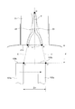
- FIG. 2 is a schematic front view of the sensor head tip surface of the optical sensor according to the present embodiment.
- the front end surface 11a of the sensor head 11 is opposed to the peripheral surface of the rotating body 103 to be measured, and as shown in FIG.
- each of the light receiving optical fibers 12 to 15 may be one or a plurality of bundles.
- the optical sensor according to this example has one end connected to the light emitting unit 2 (see FIG. 1), the other end surface exposed at the front end surface 11a, and output from the light emitting unit 2.
- An illumination optical fiber that emits illumination light from the end surface toward the peripheral surface of the rotating body 103 is provided.
- the first light receiving optical fiber 12 has one end face exposed at the tip end face 11a and the other end connected to the first light receiving section 3a (see FIG. 1). And it is the optical fiber which receives the reflected light which is the illumination light reflected by the surrounding surface of the rotary body 103 at the end surface of one end, and inputs it into the 1st light-receiving part 3a.
- the second light receiving optical fiber 13 has one end face exposed at the front end face 11a and the other end connected to the second light receiving section 3b (see FIG. 1). And it is an optical fiber which receives reflected light in the end surface of one end, and inputs it into the 2nd light-receiving part 3b.
- the third light receiving optical fiber 14 has one end face exposed at the front end face 11a and the other end connected to the third light receiving section 4a (see FIG. 1). And it is an optical fiber which receives reflected light in the end surface of one end, and inputs it into the 3rd light-receiving part 4a.
- the fourth light receiving optical fiber 15 has one end face exposed at the tip end face 11a and the other end connected to the fourth light receiving section 4b (see FIG. 1). And it is an optical fiber which receives reflected light in the end surface of one end, and inputs it into the 4th light-receiving part 4b.
- first light receiving optical fiber 12, the second light receiving optical fiber 13, the third light receiving optical fiber 14, and the fourth light receiving optical fiber 15 are arranged at the distal end in the rotation direction of the rotating body 103.
- the sensor interval refers to the interval between the end surfaces of the optical fibers on the tip surface 11 a of the sensor head 11.
- the measuring unit 5 In the measuring unit 5 (see FIG. 1), the time difference in which the first light receiving optical fiber 12 and the second light receiving optical fiber 13 receive the reflected light, and the third light receiving optical fiber 14 and the first light receiving optical fiber 13 respectively.
- the measured value of the clearance with the rotating body 103 is obtained based on the time difference in which the four light receiving optical fibers 15 receive the reflected light.
- L 1 is preferably a length of from 1.1 to 7 times in the range of L 3 (provided that the L 1 and L 3 may be reversed).
- the sensor interval L may be shifted by 1.05 times. Therefore, the lower limit is 1.1 times, which is about twice. Further, regarding the upper limit, when the height (of the sensor unit 1) of the optical sensor is fixed, the distance between the case where the angle ⁇ is generally 5 ° and the upper limit of 30 ° which can be used. The difference is about 6.6 times, so about 7 times.
- FIG. 3 is a schematic diagram for explaining the change of the clearance measurement value due to the linear expansion of the optical sensor according to the present embodiment and the compensation thereof.
- 3A shows a set of the first light receiving optical fiber 12 and the second light receiving optical fiber 13
- FIG. 3B shows the third light receiving optical fiber 14 and the fourth light receiving light. This is for a set of fibers 15.
- X 1 in FIG. 3A is an imaginary straight line that passes perpendicularly through the end face of the first light receiving optical fiber 12 at the tip face 11a when there is no linear expansion due to temperature change (ie, the first Y 1 represents the direction of reflected light incident on the end face of the light receiving optical fiber 12, and Y 1 is perpendicular to the end face of the second light receiving optical fiber 13 on the tip face 11 a when there is no linear expansion due to temperature change. (I.e., the direction of the reflected light incident on the end face of the second light receiving optical fiber 13).
- X 2 represents an imaginary straight line passing through the end face of the first light receiving optical fiber 12 at the distal end face 11a when there is linear expansion due to temperature change, and Y 2 is linear expansion due to temperature change.
- Y 2 is linear expansion due to temperature change.
- an imaginary straight line passing through the end face of the second light receiving optical fiber 13 at the front end face 11a is shown.
- ⁇ 1 in FIG. 3A is an angle at the intersection O 1 of the virtual straight lines X 1 and Y 1 .
- a 1 point and B 1 point are the positions of the end surfaces of the first light receiving optical fiber 12 and the second light receiving optical fiber 13 on the distal end surface 11a when there is no linear expansion due to temperature change.
- L 1 is the sensor interval between point A 1 and point B 1 .
- d 1 is a clearance (with the rotating body 103) when there is no linear expansion due to a temperature change.
- ⁇ 2 is an angle when there is linear expansion due to temperature change at the intersection O 1 of the virtual straight lines X 2 and Y 2 .
- Points A 2 and B 2 are the positions of the end surfaces of the first light receiving optical fiber 12 and the second light receiving optical fiber 13 on the distal end surface 11a when there is linear expansion due to temperature change.
- L 2 is the sensor interval between point A 2 and point B 2 .
- d 2 is a clearance (with the rotating body 103) when there is a linear expansion due to a temperature change.
- the broken lines X 3 , X 4 , Y 3 , Y 4 , angles ⁇ 3 , ⁇ 4 , points A 3 , A 4 , B 3 , B 4 , O 2 , and length in FIG. L 3 , L 4 , d 1 , and d 2 are also broken lines X ′ 1 , X ′ 2 , Y ′ 1 , Y ′ 2 , angles ⁇ ′ 1 , ⁇ ′ 2 , and points A ′ 1 , A ′ in FIG. 2 , B ′ 1 , B ′ 2 , O ′ and lengths L ′ 1 , L ′ 2 , d ′ 1 , d ′ 2 , respectively.
- X 3 in FIG. 3 (b) is an imaginary straight line (that is, the third straight line) passing perpendicularly through the end face of the third light receiving optical fiber 14 at the distal end face 11a when there is no linear expansion due to temperature change.
- Y 3 represents the direction of reflected light incident on the end face of the light receiving optical fiber 14, and Y 3 is perpendicular to the end face of the fourth light receiving optical fiber 15 on the front end face 11 a when there is no linear expansion due to temperature change. (Ie, the direction of the reflected light incident on the end face of the fourth light receiving optical fiber 15).
- X 4 represents an imaginary straight line that passes perpendicularly through the end face of the third light receiving optical fiber 14 at the distal end face 11a when there is linear expansion due to temperature change, and Y 4 has linear expansion due to temperature change.
- an imaginary straight line that passes perpendicularly through the end face of the fourth light receiving optical fiber 15 at the front end face 11a is shown.
- ⁇ 3 in FIG. 3B is an angle at the intersection O 2 of the virtual straight lines X 3 and Y 3 .
- Points A 3 and B 3 are the positions of the end surfaces of the third light receiving optical fiber 14 and the fourth light receiving optical fiber 15 on the tip surface 11 a when there is no linear expansion due to temperature change.
- L 3 is the sensor interval between point A 3 and point B 3 .
- ⁇ 4 is an angle when there is a linear expansion due to a temperature change at the intersection O 2 of the virtual lines X 4 and Y 4 .
- Points A 4 and B 4 are the positions of the end surfaces of the third light receiving optical fiber 14 and the fourth light receiving optical fiber 15 on the tip surface 11 a when there is linear expansion due to temperature change.
- L 4 is the sensor interval between points A 4 and B 4 . Note that d 1 and d 2 are the same as those in FIG.
- the change amount of the sensor interval at a certain temperature is ⁇
- the angle ⁇ required for clearance measurement is a numerical value that can be corrected by the change amount ⁇ , and the other is an input at the time of measurement. For this reason, the unknown variable becomes two variables of the change amount ⁇ and the clearance d. Therefore, the two sets described above (the set of the first light receiving optical fiber 12 and the second light receiving optical fiber 13 and the third light receiving light) are used. From the result of the clearance measurement of the optical fiber 14 and the fourth light-receiving optical fiber 15), the clearance d 2 (with the rotating body 103) when there is linear expansion due to the change amount ⁇ and the temperature change (finally) The clearance measurement value to be obtained can be calculated. Thereby, in a present Example, clearance measurement precision can be improved. In the following, a more detailed calculation will be described in this regard.
- the sensor interval L and the clearance d are coefficients that change as the temperature changes.
- C refers to the “height of the optical sensor”, that is, the distance from the intersection point O 1 to the straight line A 1 B 1 in FIG.
- C refers to the “height of the optical sensor”, that is, the distance from the intersection O 2 to the straight line A 3 B 3 in FIG. 3B, and is equal to C in the above equation (2). .
- the first light receiving optical fiber 12 and the second light receiving optical fiber 13 are different from each other.
- the sensor interval considering the linear expansion due to the temperature change is that ⁇ in the above equation (0) is ⁇ 2 , L is L 2, and further, from the above equations (1) and (5), It becomes.
- the third light receiving optical fiber 14 and the fourth light receiving optical fiber 15 receive the reflected light
- ⁇ t 2 the third light receiving optical fiber 14 and the fourth light receiving optical fiber 15 are received.
- the sensor interval in consideration of the linear expansion due to the temperature change is expressed by the equation (0) where ⁇ is ⁇ 4 , L is L 4, and from the above equations (7) and (8),
- the unknown variables in the above formulas (9) and (10) are ⁇ and d 2.
- the present invention is suitable as an optical sensor, a rotary machine including the optical sensor, and a clearance measuring method.
Landscapes
- Physics & Mathematics (AREA)
- General Physics & Mathematics (AREA)
- Length Measuring Devices By Optical Means (AREA)
Abstract
第1の受光用光ファイバ(12)、第2の受光用光ファイバ(13)、第3の受光用光ファイバ(14)、及び、第4の受光用光ファイバ(15)が、回転体(103)の回転方向における、センサヘッド(11)の先端面(11a)の、第1の受光用光ファイバ(12)と第2の受光用光ファイバ(13)とのセンサ間隔と、第3の受光用光ファイバ(14)と第4の受光用光ファイバ(15)とのセンサ間隔とが異なるようにして配置された、光学センサを用いることで、熱伸びによる影響を補償し、高精度にクリアランスを計測することができる。
Description
本発明は、光学センサ、該光学センサを備える回転機械、及び、クリアランス計測方法に関する。
タービン機械の性能向上のためには、チップクリアランスを小さくする必要がある。そこで、このチップクリアランスを高精度で計測することが求められる。さらには、回転機械全般において、回転側と静止側のクリアランスを高精度で計測することが求められる。
高温・高圧水蒸気環境下でクリアランスを計測するには、解決すべき課題が多く、例えば、静電容量式のクリアランスセンサは、このような環境下において、劣化による絶縁不良が発生する可能性があり、さらに、誘電率変化の影響を受けるため、使用することができない。
その点、光ファイバ式のクリアランスセンサ(光学センサ)は、高温・高圧水蒸気環境下における影響を受けることがなく、使用に適している。光学センサとして、例えば上記特許文献1には、3つの計測点を用いて3次元座標を計測する技術が開示されている。
しかしながら、光学センサのセンサヘッドの先端面に露出する光ファイバ(あるいはファイバの束)の端面は、互いに規定の間隔(基準距離)で固定されているが、光学センサに熱膨張が生じることで、この間隔が変化してしまう。そして、このような形状の変化は、クリアランス計測精度が低下する原因となる。
したがって本発明では、上記技術的課題に鑑み、熱膨張による影響を補償し、高精度にクリアランスを計測することができる、光学センサ及び回転機械を提供することを目的とする。
上記課題を解決する第1の発明に係る光学センサは、
センサヘッドの先端面が回転体の周面に対向しており、
前記周面からの光を、前記センサヘッドの先端面において露出した端面にて受光する、第1の受光用光ファイバと、
前記周面からの光を、前記センサヘッドの先端面において露出した端面にて受光する、第2の受光用光ファイバと、
前記周面からの光を、前記センサヘッドの先端面において露出した端面にて受光する、第3の受光用光ファイバと、
前記周面からの光を、前記センサヘッドの先端面において露出した端面にて受光する、第4の受光用光ファイバとを備え、
前記第1の受光用光ファイバ、前記第2の受光用光ファイバ、前記第3の受光用光ファイバ、及び、前記第4の受光用光ファイバは、前記回転体の回転方向における、前記センサヘッドの先端面の、前記第1の受光用光ファイバと前記第2の受光用光ファイバとの間隔と、前記第3の受光用光ファイバと前記第4の受光用光ファイバとの間隔とが異なるようにして配置されており、
さらに、
前記第1の受光用光ファイバ及び前記第2の受光用光ファイバがそれぞれ前記周面からの光を受光する時間差、及び、前記第3の受光用光ファイバ及び前記第4の受光用光ファイバが前記周面からの光を受光する時間差に基づき、前記回転体とのクリアランスの計測値を求める、計測部を備える
ことを特徴とする。
センサヘッドの先端面が回転体の周面に対向しており、
前記周面からの光を、前記センサヘッドの先端面において露出した端面にて受光する、第1の受光用光ファイバと、
前記周面からの光を、前記センサヘッドの先端面において露出した端面にて受光する、第2の受光用光ファイバと、
前記周面からの光を、前記センサヘッドの先端面において露出した端面にて受光する、第3の受光用光ファイバと、
前記周面からの光を、前記センサヘッドの先端面において露出した端面にて受光する、第4の受光用光ファイバとを備え、
前記第1の受光用光ファイバ、前記第2の受光用光ファイバ、前記第3の受光用光ファイバ、及び、前記第4の受光用光ファイバは、前記回転体の回転方向における、前記センサヘッドの先端面の、前記第1の受光用光ファイバと前記第2の受光用光ファイバとの間隔と、前記第3の受光用光ファイバと前記第4の受光用光ファイバとの間隔とが異なるようにして配置されており、
さらに、
前記第1の受光用光ファイバ及び前記第2の受光用光ファイバがそれぞれ前記周面からの光を受光する時間差、及び、前記第3の受光用光ファイバ及び前記第4の受光用光ファイバが前記周面からの光を受光する時間差に基づき、前記回転体とのクリアランスの計測値を求める、計測部を備える
ことを特徴とする。
上記課題を解決する第2の発明に係る光学センサは、
上記第1の発明に係る光学センサにおいて、
前記計測部は、下記2つの式により、前記クリアランスの計測値を求める
ことを特徴とする。


ただし、
d2は、前記クリアランスの計測値
Rは、前記回転体の半径
Δt1は、前記第1の受光用光ファイバ及び前記第2の受光用光ファイバがそれぞれ反射光を受光する時間差
Δt2は、前記第3の受光用光ファイバ及び前記第4の受光用光ファイバがそれぞれ反射光を受光する時間差
βは、ある温度での、前記第1受光用光ファイバと前記第2の受光用光ファイバとの間隔の変化量、及び、前記第1受光用光ファイバと前記第2の受光用光ファイバとの間隔の変化量
L1は、前記第1の受光用光ファイバと前記第2の受光用光ファイバとの間隔
L3は、前記第3の受光用光ファイバと前記第4の受光用光ファイバとの間隔
α1は、温度変化による線膨張がないとした場合の、前記第1の受光用光ファイバの前記端面に入射する前記周面からの光の方向と、前記第2の受光用光ファイバの前記端面に入射する前記周面からの光の方向との角度
α3は、温度変化による線膨張がないとした場合の、前記第3の受光用光ファイバの前記端面に入射する前記周面からの光の方向と、前記第4の受光用光ファイバの前記端面に入射する前記周面からの光の方向との角度
とする。
上記第1の発明に係る光学センサにおいて、
前記計測部は、下記2つの式により、前記クリアランスの計測値を求める
ことを特徴とする。
d2は、前記クリアランスの計測値
Rは、前記回転体の半径
Δt1は、前記第1の受光用光ファイバ及び前記第2の受光用光ファイバがそれぞれ反射光を受光する時間差
Δt2は、前記第3の受光用光ファイバ及び前記第4の受光用光ファイバがそれぞれ反射光を受光する時間差
βは、ある温度での、前記第1受光用光ファイバと前記第2の受光用光ファイバとの間隔の変化量、及び、前記第1受光用光ファイバと前記第2の受光用光ファイバとの間隔の変化量
L1は、前記第1の受光用光ファイバと前記第2の受光用光ファイバとの間隔
L3は、前記第3の受光用光ファイバと前記第4の受光用光ファイバとの間隔
α1は、温度変化による線膨張がないとした場合の、前記第1の受光用光ファイバの前記端面に入射する前記周面からの光の方向と、前記第2の受光用光ファイバの前記端面に入射する前記周面からの光の方向との角度
α3は、温度変化による線膨張がないとした場合の、前記第3の受光用光ファイバの前記端面に入射する前記周面からの光の方向と、前記第4の受光用光ファイバの前記端面に入射する前記周面からの光の方向との角度
とする。
上記課題を解決する第3の発明に係る光学センサは、
上記第1の発明に係る光学センサにおいて、
前記第1の受光用光ファイバと前記第2の受光用光ファイバとの間隔と、前記第3の受光用光ファイバと前記第4の受光用光ファイバとの間隔とは、一方が他方に対し、1.1倍から7倍の範囲の長さである
ことを特徴とする。
上記第1の発明に係る光学センサにおいて、
前記第1の受光用光ファイバと前記第2の受光用光ファイバとの間隔と、前記第3の受光用光ファイバと前記第4の受光用光ファイバとの間隔とは、一方が他方に対し、1.1倍から7倍の範囲の長さである
ことを特徴とする。
上記課題を解決する第4の発明に係る光学センサは、
上記第1の発明に係る光学センサにおいて、
前記センサヘッドの先端面において露出した端面から前記周面に向けて照明光を出射する、照明用光ファイバを備える
ことを特徴とする。
上記第1の発明に係る光学センサにおいて、
前記センサヘッドの先端面において露出した端面から前記周面に向けて照明光を出射する、照明用光ファイバを備える
ことを特徴とする。
上記課題を解決する第5の発明に係る回転機械は、
ハウジング内に、該ハウジングの内周面とクリアランスを有して配された回転体を備え、
さらに、
前記センサヘッドが前記ハウジングの内周面に配されるようにして、前記第1の発明に係る光学センサが設けられる
ことを特徴とする。
ハウジング内に、該ハウジングの内周面とクリアランスを有して配された回転体を備え、
さらに、
前記センサヘッドが前記ハウジングの内周面に配されるようにして、前記第1の発明に係る光学センサが設けられる
ことを特徴とする。
上記課題を解決する第6の発明に係るクリアランス計測方法は、
回転体の周面からの光を、センサヘッドの先端面において露出した端面にて受光する、第1の受光用光ファイバと、
前記周面からの光を、前記センサヘッドの先端面において露出した端面にて受光する、第2の受光用光ファイバと、
前記周面からの光を、前記センサヘッドの先端面において露出した端面にて受光する、第3の受光用光ファイバと、
前記周面からの光を、前記センサヘッドの先端面において露出した端面にて受光する、第4の受光用光ファイバとを備え、
前記第1の受光用光ファイバ、前記第2の受光用光ファイバ、前記第3の受光用光ファイバ、及び、前記第4の受光用光ファイバは、前記回転体の回転方向における、前記センサヘッドの先端面の、前記第1の受光用光ファイバと前記第2の受光用光ファイバとの間隔と、前記第3の受光用光ファイバと前記第4の受光用光ファイバとの間隔とが異なるようにして配置された、光学センサを、
前記センサヘッドの先端面を前記周面に対向させ、
前記第1の受光用光ファイバ及び前記第2の受光用光ファイバがそれぞれ前記周面からの光を受光する時間差、及び、前記第3の受光用光ファイバ及び前記第4の受光用光ファイバが前記周面からの光を受光する時間差に基づき、前記回転体とのクリアランスの計測値を求める
ことを特徴とする。
回転体の周面からの光を、センサヘッドの先端面において露出した端面にて受光する、第1の受光用光ファイバと、
前記周面からの光を、前記センサヘッドの先端面において露出した端面にて受光する、第2の受光用光ファイバと、
前記周面からの光を、前記センサヘッドの先端面において露出した端面にて受光する、第3の受光用光ファイバと、
前記周面からの光を、前記センサヘッドの先端面において露出した端面にて受光する、第4の受光用光ファイバとを備え、
前記第1の受光用光ファイバ、前記第2の受光用光ファイバ、前記第3の受光用光ファイバ、及び、前記第4の受光用光ファイバは、前記回転体の回転方向における、前記センサヘッドの先端面の、前記第1の受光用光ファイバと前記第2の受光用光ファイバとの間隔と、前記第3の受光用光ファイバと前記第4の受光用光ファイバとの間隔とが異なるようにして配置された、光学センサを、
前記センサヘッドの先端面を前記周面に対向させ、
前記第1の受光用光ファイバ及び前記第2の受光用光ファイバがそれぞれ前記周面からの光を受光する時間差、及び、前記第3の受光用光ファイバ及び前記第4の受光用光ファイバが前記周面からの光を受光する時間差に基づき、前記回転体とのクリアランスの計測値を求める
ことを特徴とする。
上記課題を解決する第7の発明に係るクリアランス計測方法は、
上記第6の発明に係るクリアランス計測方法において、
下記2つの式により、前記クリアランスの計測値を求める
ことを特徴とする。


ただし、
d2は、前記クリアランスの計測値
Rは、前記回転体の半径
Δt1は、前記第1の受光用光ファイバ及び前記第2の受光用光ファイバがそれぞれ反射光を受光する時間差
Δt2は、前記第3の受光用光ファイバ及び前記第4の受光用光ファイバがそれぞれ反射光を受光する時間差
βは、ある温度での、前記第1受光用光ファイバと前記第2の受光用光ファイバとの間隔の変化量、及び、前記第1受光用光ファイバと前記第2の受光用光ファイバとの間隔の変化量
L1は、前記第1の受光用光ファイバと前記第2の受光用光ファイバとの間隔
L3は、前記第3の受光用光ファイバと前記第4の受光用光ファイバとの間隔
α1は、温度変化による線膨張がないとした場合の、前記第1の受光用光ファイバの前記端面に入射する前記周面からの光の方向と、前記第2の受光用光ファイバの前記端面に入射する前記周面からの光の方向との角度
α3は、温度変化による線膨張がないとした場合の、前記第3の受光用光ファイバの前記端面に入射する前記周面からの光の方向と、前記第4の受光用光ファイバの前記端面に入射する前記周面からの光の方向との角度
とする。
上記第6の発明に係るクリアランス計測方法において、
下記2つの式により、前記クリアランスの計測値を求める
ことを特徴とする。
d2は、前記クリアランスの計測値
Rは、前記回転体の半径
Δt1は、前記第1の受光用光ファイバ及び前記第2の受光用光ファイバがそれぞれ反射光を受光する時間差
Δt2は、前記第3の受光用光ファイバ及び前記第4の受光用光ファイバがそれぞれ反射光を受光する時間差
βは、ある温度での、前記第1受光用光ファイバと前記第2の受光用光ファイバとの間隔の変化量、及び、前記第1受光用光ファイバと前記第2の受光用光ファイバとの間隔の変化量
L1は、前記第1の受光用光ファイバと前記第2の受光用光ファイバとの間隔
L3は、前記第3の受光用光ファイバと前記第4の受光用光ファイバとの間隔
α1は、温度変化による線膨張がないとした場合の、前記第1の受光用光ファイバの前記端面に入射する前記周面からの光の方向と、前記第2の受光用光ファイバの前記端面に入射する前記周面からの光の方向との角度
α3は、温度変化による線膨張がないとした場合の、前記第3の受光用光ファイバの前記端面に入射する前記周面からの光の方向と、前記第4の受光用光ファイバの前記端面に入射する前記周面からの光の方向との角度
とする。
上記課題を解決する第8の発明に係るクリアランス計測方法は、
上記第6の発明に係るクリアランス計測方法において、
前記光学センサは、前記第1の受光用光ファイバと前記第2の受光用光ファイバとの間隔と、前記第3の受光用光ファイバと前記第4の受光用光ファイバとの間隔とは、一方が他方に対し、1.1倍から7倍の範囲の長さである
ことを特徴とする。
上記第6の発明に係るクリアランス計測方法において、
前記光学センサは、前記第1の受光用光ファイバと前記第2の受光用光ファイバとの間隔と、前記第3の受光用光ファイバと前記第4の受光用光ファイバとの間隔とは、一方が他方に対し、1.1倍から7倍の範囲の長さである
ことを特徴とする。
上記課題を解決する第9の発明に係るクリアランス計測方法は、
上記第6の発明に係るクリアランス計測方法において、
前記光学センサは、前記センサヘッドの先端面において露出した端面から前記周面に向けて照明光を出射する、照明用光ファイバを備える
ことを特徴とする。
上記第6の発明に係るクリアランス計測方法において、
前記光学センサは、前記センサヘッドの先端面において露出した端面から前記周面に向けて照明光を出射する、照明用光ファイバを備える
ことを特徴とする。
本発明に係る光学センサ、回転機械及びクリアランス計測方法によれば、熱膨張による影響を補償し、高精度にクリアランスを計測することができる。
図1は、本発明に係る回転機械を説明する概略図である。図1に示すように、本発明に係る回転機械は、ハウジング101内において、回転軸102に固定され、ハウジング101の内周面とクリアランスを有して配された回転体103を備え、さらに、センサヘッドがハウジング101の内周面に配されるようにして、本発明に係る光学センサが設けられている。
本発明に係る光学センサについてより詳述すると、ハウジング101の内周面において、先端面が計測対象である回転体103側を向くようにして配されるセンサ部1、それぞれ第1~4の受光用光ファイバを介してセンサ部1に接続する第1~4受光部3a,3b,4a,4b、照明用光ファイバを介してセンサ部1に接続する発光部2、及び、第1~4受光部3a,3b,4a,4bに接続する計測部5を備えている(図1中では、第1~4の受光用光ファイバ及び照明用光ファイバをまとめて符号6で示している)。
計測の大まかな手順としては、まず、回転機械の駆動中において、発光部2から照明用光ファイバを介してセンサ部1へ照明光が出力され、この照明光がセンサ部1の先端部(センサヘッド)から回転体103へ向けて放出される。
照明光は回転体103の周面において反射し、その反射光の一部は、センサヘッドに入射し、第1~4の受光用光ファイバを介してそれぞれ第1~4受光部3a,3b,4a,4bへ、それぞれ入力される。
このとき、回転体103からセンサヘッドに入射する反射光は、回転体103の周面において周方向(回転方向)に変化する形状等に依存した、所定の強度周期を有している。例えば、回転体103がタービンである場合には動翼の形状に依存した強度周期となる。
計測部5では、第1~4受光部3a,3b,4a,4bにそれぞれ入力される反射光のタイミングに基づき、回転体103とのクリアランスを計測する。
以上が、本発明に係る回転機械に設けられた光学センサによる計測の手順である。
以上が、本発明に係る回転機械に設けられた光学センサによる計測の手順である。
以下、本発明に係る光学センサ及びクリアランス計測方法を実施例にて詳述する。なお、下記実施例では、タービンに光学センサを配するものとして説明している箇所が一部あるが、本発明はこれに限らず、回転機械全般に適用可能である。
本実施例に係る光学センサは、レーザ光を利用して三角計測を行うことで、クリアランス計測を行うものである。
まず、三角計測を用いた一般的な光学センサの熱伸びによるクリアランス計測値への影響を検討する。図4は、タービンを例として、三角計測を用いた一般的な光学センサの回転体とのクリアランス(チップクリアランス)計測を説明する模式図であり、図中の破線矢印は、回転体103(図1参照)の動翼103aの回転方向を示している。図4に示すように、この光学センサは、第1´の受光用光ファイバ22及び第2´の受光用光ファイバ23の2本(又は複数本ずつの束)を備えている。
まず、センサヘッド21の先端面21aは、計測対象である回転体103(図1参照)の周面に対向している。
センサヘッド21の先端面21aにおける第1´の受光用光ファイバ22の端面の位置をA点、第2´の受光用光ファイバ23の端面の位置をB点とする。また、動翼103aの外側端面103bにおける角部(二つの角部のうち回転方向前方側の角部)が、先端面21aにおける、第1´の受光用光ファイバ22の端面を垂直に通る仮想直線X(すなわち第1´の受光用光ファイバ22の端面に入射する反射光の方向)と交わる点をC点とし、先端面21aにおける、第2´の受光用光ファイバ23の端面を垂直に通る仮想直線Y(すなわち第2´の受光用光ファイバ23の端面に入射する反射光の方向)と交わる点をD点とする(仮想直線は図中に破線で表している)。なお、この角部とは、第1´の受光用光ファイバ22及び第2´の受光用光ファイバ23へ入射する反射光の強度が(急激に)変化する箇所である。
さらに、動翼103aが、C点からD点まで移動する時間をΔtとする。このΔtは、第1´の受光用光ファイバ22及び第2´の受光用光ファイバ23がそれぞれ反射光を受光する時間差となる。また、センサヘッド21の先端面21aと動翼103aの外側端面103bとのクリアランスをdとする。また、A点とB点との間隔をセンサ間隔(センサヘッド21の先端面21aにおける光ファイバの端面同士の間隔)Lとする。
すると、下記式(0)が成立する。

ただし、Rを回転体103の半径、Tを回転体103の周期とする。
ここで、図5は、上記構成とした光学センサの熱膨張(以下、線膨張)によるクリアランス計測値の変化を示す模式図である。図5中のX´1は、温度変化による線膨張がないとした場合の上記仮想直線Xを表し、Y´1は、温度変化による線膨張がないとした場合の上記仮想直線Yを表している。また、X´2は、温度変化による線膨張がある場合の上記仮想直線Xを表し、Y´2は、温度変化による線膨張がある場合の上記仮想直線Yを表している。
図5中のα´1は、上述した2つの仮想直線の交点O´における温度変化による線膨張がないとした場合の角度である。A´1点,B´1点は、温度変化による線膨張がないとした場合の上記A点,B点である。L´1は、A´1点とB´1点とのセンサ間隔である。d´1は、温度変化による線膨張がないとした場合の上記クリアランスdである。また、α´2は、上述した2つの仮想直線の交点O´における温度変化による線膨張がある場合の角度である。A´2点,B´2点は、温度変化による線膨張がある場合の上記A点,B点である。L´2は、A´2点とB´2点とのセンサ間隔である。d´2は、温度変化による線膨張がある場合の上記クリアランスdである。
温度変化による線膨張がないとした場合、チップクリアランスとして計測されるのはd´1である。しかし実際には、線膨張の影響により、A´1点,B´1点がA´2点,B´2点となり、L´1がL´2となるため、正しいチップクリアランスはd´2となり、このd´1とd´2との差が計測誤差となる。
そこで本実施例では、室温からの温度上昇による線膨張の影響によって発生するセンサ間隔Lの変化量を考慮するために、互いに異なるセンサ間隔を有する2組以上の受光用光ファイバによるクリアランス計測を行う。
図2は、本実施例に係る光学センサのセンサヘッド先端面の概略的正面図である。本実施例に係る光学センサは、センサヘッド11の先端面11aは、計測対象である回転体103の周面に対向し、図2に示すように、第1の受光用光ファイバ12、第2の受光用光ファイバ13、第3の受光用光ファイバ14、及び、第4の受光用光ファイバ15を備えている。
なお、受光用光ファイバ12~15は、それぞれ1本であっても複数本の束であってもよい。また、図示していないが、本実施例に係る光学センサは、一端が発光部2(図1参照)に接続し、他端の端面が先端面11aにおいて露出し、発光部2から出力された照明光を、端面から回転体103の周面に向けて出射する照明用光ファイバを備えている。
第1の受光用光ファイバ12は、一端の端面が先端面11aにおいて露出し、他端が第1受光部3a(図1参照)に接続している。そして、回転体103の周面にて反射された照明光である反射光を、一端の端面にて受光し、第1受光部3aへ入力する光ファイバである。
第2の受光用光ファイバ13は、一端の端面が先端面11aにおいて露出し、他端が第2受光部3b(図1参照)に接続している。そして、反射光を一端の端面にて受光し、第2受光部3bへ入力する光ファイバである。
第3の受光用光ファイバ14は、一端の端面が先端面11aにおいて露出し、他端が第3受光部4a(図1参照)に接続している。そして、反射光を一端の端面にて受光し、第3受光部4aへ入力する光ファイバである。
第4の受光用光ファイバ15は、一端の端面が先端面11aにおいて露出し、他端が第4受光部4b(図1参照)に接続している。そして、反射光を一端の端面にて受光し、第4受光部4bへ入力する光ファイバである。
また、第1の受光用光ファイバ12、第2の受光用光ファイバ13、第3の受光用光ファイバ14、及び、第4の受光用光ファイバ15は、回転体103の回転方向における、先端面11aの、第1の受光用光ファイバ12(の端面)と第2の受光用光ファイバ13(の端面)とのセンサ間隔L1と、第3の受光用光ファイバ14(の端面)と第4の受光用光ファイバ(の端面)とのセンサ間隔L3とが異なるようにして配置されている。なお、センサ間隔とは、センサヘッド11の先端面11aにおける光ファイバの端面同士の間隔を指す。
そして、計測部5(図1参照)では、第1の受光用光ファイバ12及び第2の受光用光ファイバ13がそれぞれ反射光を受光する時間差、及び、第3の受光用光ファイバ14及び第4の受光用光ファイバ15が反射光を受光する時間差に基づき、回転体103とのクリアランスの計測値を求める。
また、例えばL1>L3とすると、L1はL3の1.1~7倍の範囲の長さとするのが好ましい(ただし、L1とL3とが逆でもよい)。
すなわち、簡易的に角度α(図4参照)が変化しないとして、クリアランス測定の誤差が0.1mmとした場合に、センサ間隔L(図4参照)は1.05倍のずれがあり得る。そのため、約2倍の1.1倍を下限とする。さらに、上限については、光学センサの(センサ部1の)高さを固定したときに、角度αが、一般的に用いられる5°の場合と、使用可能上限である30°の場合との距離の差が約6.6倍であるため、約7倍とする。
以上が本実施例に係る光学センサの構成である。以下では、本実施例におけるクリアランス計測の手順について説明する。なお、以下の手順は、計測部5により行われる。
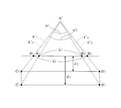
図3は、本実施例に係る光学センサの線膨張によるクリアランス計測値の変化及びその補償を説明する模式図である。図3(a)は、第1の受光用光ファイバ12及び第2の受光用光ファイバ13の組について、図3(b)は、第3の受光用光ファイバ14及び第4の受光用光ファイバ15の組についてのものである。
図3(a)中の破線X1,X2,Y1,Y2、角度α1,α2、各点A1,A2,B1,B2,O1、及び、長さL1,L2,d1,d2は、図5における破線X´1,X´2,Y´1,Y´2、角度α´1,α´2、各点A´1,A´2,B´1,B´2,O´、及び、長さL´1,L´2,d´1,d´2に、それぞれ対応している。
すなわち、図3(a)中のX1は、温度変化による線膨張がないとした場合の、先端面11aにおける第1の受光用光ファイバ12の端面を垂直に通る仮想直線(すなわち第1の受光用光ファイバ12の端面に入射する反射光の方向)を表し、Y1は、温度変化による線膨張がないとした場合の、先端面11aにおける第2の受光用光ファイバ13の端面を垂直に通る仮想直線(すなわち第2の受光用光ファイバ13の端面に入射する反射光の方向)を表している。また、X2は、温度変化による線膨張がある場合の、先端面11aにおける第1の受光用光ファイバ12の端面を垂直に通る仮想直線を表し、Y2は、温度変化による線膨張がある場合の、先端面11aにおける第2の受光用光ファイバ13の端面を垂直に通る仮想直線を表している。
さらに、図3(a)中のα1は、仮想直線X1とY1の交点O1における角度である。A1点,B1点は、温度変化による線膨張がないとした場合の、先端面11aにおける第1の受光用光ファイバ12,第2の受光用光ファイバ13の端面の位置である。L1は、A1点とB1点とのセンサ間隔である。d1は、温度変化による線膨張がないとした場合の(回転体103との)クリアランスである。また、α2は、仮想直線X2とY2の交点O1における、温度変化による線膨張がある場合の角度である。A2点,B2点は、温度変化による線膨張がある場合の、先端面11aにおける第1の受光用光ファイバ12、第2の受光用光ファイバ13の端面の位置である。L2は、A2点とB2点とのセンサ間隔である。d2は、温度変化による線膨張がある場合の(回転体103との)クリアランスである。
そして、図3(b)中の破線X3,X4,Y3,Y4、角度α3,α4、各点A3,A4,B3,B4,O2、及び、長さL3,L4,d1,d2も、図5における破線X´1,X´2,Y´1,Y´2、角度α´1,α´2、各点A´1,A´2,B´1,B´2,O´、及び、長さL´1,L´2,d´1,d´2に、それぞれ対応している。
すなわち、図3(b)中のX3は、温度変化による線膨張がないとした場合の、先端面11aにおける第3の受光用光ファイバ14の端面を垂直に通る仮想直線(すなわち第3の受光用光ファイバ14の端面に入射する反射光の方向)を表し、Y3は、温度変化による線膨張がないとした場合の、先端面11aにおける第4の受光用光ファイバ15の端面を垂直に通る仮想直線(すなわち第4の受光用光ファイバ15の端面に入射する反射光の方向)を表している。また、X4は、温度変化による線膨張がある場合の、先端面11aにおける第3の受光用光ファイバ14の端面を垂直に通る仮想直線を表し、Y4は、温度変化による線膨張がある場合の、先端面11aにおける第4の受光用光ファイバ15の端面を垂直に通る仮想直線を表している。
さらに、図3(b)中のα3は、仮想直線X3とY3の交点O2における角度である。A3点,B3点は、温度変化による線膨張がないとした場合の、先端面11aにおける第3の受光用光ファイバ14,第4の受光用光ファイバ15の端面の位置である。L3は、A3点とB3点とのセンサ間隔である。また、α4は、仮想直線X4とY4の交点O2における、温度変化による線膨張がある場合の角度である。A4点,B4点は、温度変化による線膨張がある場合の、先端面11aにおける第3の受光用光ファイバ14,第4の受光用光ファイバ15の端面の位置である。L4は、A4点とB4点とのセンサ間隔である。なお、d1,d2については、図3(a)と同様である。
ここで、ある温度でのセンサ間隔の変化量をβとすると、第1の受光用光ファイバ12及び第2の受光用光ファイバ13のセンサ間隔の変化量は、(L2-L1)/L1=βとなり、第3の受光用光ファイバ14及び第4の受光用光ファイバ15のセンサ間隔の変化量は、(L4-L3)/L3=βとなる。
クリアランス計測に必要となる角度αは、変化量βで補正できる数値であり、その他は計測時のインプットとなる。そのため、未知の変数は、変化量βとクリアランスdの2変数となるため、上述した2つの組(第1の受光用光ファイバ12及び第2の受光用光ファイバ13の組、第3の受光用光ファイバ14及び第4の受光用光ファイバ15の組)のクリアランス計測の結果から、変化量β及び温度変化による線膨張がある場合の(回転体103との)クリアランスd2(最終的に求めるべきクリアランス計測値)を算出することができる。これにより本実施例では、クリアランス計測精度を向上させることができる。
以下では、この点につき、より詳細な計算を説明する。
以下では、この点につき、より詳細な計算を説明する。
まず、センサ間隔Lとクリアランスdが、温度変化に伴い変化する係数となる。
温度上昇による第1の受光用光ファイバ12と第2の受光用光ファイバ13とのセンサ間隔は、
(L2-L1)/L1=β …(1)
とする。
(L2-L1)/L1=β …(1)
とする。
また、初期状態(例えば室温)での角度α1(上述では角度α1は温度変化による線膨張がないとした場合の角度であるとしたが、これを換言すれば、初期状態での角度ということである)は、
C/(L1/2)=tan(α1/2) …(2)
とする。
なお、ここでのCとは、上記「光学センサの高さ」、すなわち、図3(a)における交点O1から直線A1B1までの距離を指す。
C/(L1/2)=tan(α1/2) …(2)
とする。
なお、ここでのCとは、上記「光学センサの高さ」、すなわち、図3(a)における交点O1から直線A1B1までの距離を指す。
温度上昇後の角度α2(上述では角度α2は温度変化による線膨張がある場合の角度であるとしたが、これを換言すれば、温度上昇後の角度ということである)は、
C/(L2/2)=tan(α2/2) …(3)
となる。
なお、ここでのCとは、上記「光学センサの高さ」、すなわち、図3(b)における交点O2から直線A3B3までの距離を指し、上記式(2)におけるCと等しい。
C/(L2/2)=tan(α2/2) …(3)
となる。
なお、ここでのCとは、上記「光学センサの高さ」、すなわち、図3(b)における交点O2から直線A3B3までの距離を指し、上記式(2)におけるCと等しい。
ここで、上記式(1)より、L2=L1(β+1)となるために上記式(3)は、
C/{L1(β+1)/2}=tan(α2/2) …(4)
となる。
C/{L1(β+1)/2}=tan(α2/2) …(4)
となる。
上記式(4)に上記式(2)を代入することで、
{1/(β+1)}×tan(α1/2)=tan(α2/2) …(5)
となる。
そのため、角度αについてもβの変数となる。
{1/(β+1)}×tan(α1/2)=tan(α2/2) …(5)
となる。
そのため、角度αについてもβの変数となる。
温度上昇による第3の受光用光ファイバ14と第4の受光用光ファイバ15とのセンサ間隔は、上記式(1)と同様に、
(L4-L3)/L3=γ …(6)
(L4-L3)/L3=γ …(6)
ここで、γは第3の受光用光ファイバ14と第4の受光用光ファイバ15とのセンサ間隔の変化量となるが、線膨張の変化により、第1の受光用光ファイバ12と第2の受光用光ファイバ13とのセンサ間隔と、第3の受光用光ファイバ14と第4の受光用光ファイバ15とのセンサ間隔の変化量とは、温度が同じであれば等しくなる(β=γ)。そのため、上記式(6)は、
(L4-L3)/L3=β …(7)
となる。
(L4-L3)/L3=β …(7)
となる。
また、角度α3,α4についても上記式(4)と同様に、
{1/(β+1)}×tan(α3/2)=tan(α4/2) …(8)
となる。
{1/(β+1)}×tan(α3/2)=tan(α4/2) …(8)
となる。
第1の受光用光ファイバ12及び第2の受光用光ファイバ13がそれぞれ反射光を受光する時間差をΔt1とすると、第1の受光用光ファイバ12と第2の受光用光ファイバ13との温度変化による線膨張を考慮したセンサ間隔は、上記式(0)のαをα2、LをL2とし、さらに、上記式(1),(5)より、

となる。
また、第3の受光用光ファイバ14及び第4の受光用光ファイバ15がそれぞれ反射光を受光する時間差をΔt2とすると、第3の受光用光ファイバ14と第4の受光用光ファイバ15との温度変化による線膨張を考慮したセンサ間隔は、上記式(0)のαをα4、LをL4とし、さらに、上記式(7),(8)より、

上記式(9),(10)で未知の変数はβ及びd2であり、これらの値を上記式(9),(10)から求めることで、温度変化による線膨張を考慮したクリアランス計測が可能となる。
本発明は、光学センサ、該光学センサを備える回転機械、及び、クリアランス計測方法として好適である。
1 センサ部
2 発光部
3a 第1受光部
3b 第2受光部
4a 第3受光部
4b 第4受光部
5 計測部
11,21 センサヘッド
11a,21a (センサヘッドの)先端面
12 第1の受光用光ファイバ
13 第2の受光用光ファイバ
14 第3の受光用光ファイバ
15 第4の受光用光ファイバ
22 第1´の受光用光ファイバ
23 第2´の受光用光ファイバ
101 ハウジング
102 回転軸
103 回転体
103a 動翼
103b 外側端面
2 発光部
3a 第1受光部
3b 第2受光部
4a 第3受光部
4b 第4受光部
5 計測部
11,21 センサヘッド
11a,21a (センサヘッドの)先端面
12 第1の受光用光ファイバ
13 第2の受光用光ファイバ
14 第3の受光用光ファイバ
15 第4の受光用光ファイバ
22 第1´の受光用光ファイバ
23 第2´の受光用光ファイバ
101 ハウジング
102 回転軸
103 回転体
103a 動翼
103b 外側端面
Claims (9)
- センサヘッドの先端面が回転体の周面に対向しており、
前記周面からの光を、前記センサヘッドの先端面において露出した端面にて受光する、第1の受光用光ファイバと、
前記周面からの光を、前記センサヘッドの先端面において露出した端面にて受光する、第2の受光用光ファイバと、
前記周面からの光を、前記センサヘッドの先端面において露出した端面にて受光する、第3の受光用光ファイバと、
前記周面からの光を、前記センサヘッドの先端面において露出した端面にて受光する、第4の受光用光ファイバとを備え、
前記第1の受光用光ファイバ、前記第2の受光用光ファイバ、前記第3の受光用光ファイバ、及び、前記第4の受光用光ファイバは、前記回転体の回転方向における、前記センサヘッドの先端面の、前記第1の受光用光ファイバと前記第2の受光用光ファイバとの間隔と、前記第3の受光用光ファイバと前記第4の受光用光ファイバとの間隔とが異なるようにして配置されており、
さらに、
前記第1の受光用光ファイバ及び前記第2の受光用光ファイバがそれぞれ前記周面からの光を受光する時間差、及び、前記第3の受光用光ファイバ及び前記第4の受光用光ファイバが前記周面からの光を受光する時間差に基づき、前記回転体とのクリアランスの計測値を求める、計測部を備える
ことを特徴とする光学センサ。 - 前記計測部は、下記2つの式により、前記クリアランスの計測値を求める
ことを特徴とする請求項1に記載の光学センサ。


d2は、前記クリアランスの計測値
Rは、前記回転体の半径
Δt1は、前記第1の受光用光ファイバ及び前記第2の受光用光ファイバがそれぞれ反射光を受光する時間差
Δt2は、前記第3の受光用光ファイバ及び前記第4の受光用光ファイバがそれぞれ反射光を受光する時間差
βは、ある温度での、前記第1受光用光ファイバと前記第2の受光用光ファイバとの間隔の変化量、及び、前記第1受光用光ファイバと前記第2の受光用光ファイバとの間隔の変化量
L1は、前記第1の受光用光ファイバと前記第2の受光用光ファイバとの間隔
L3は、前記第3の受光用光ファイバと前記第4の受光用光ファイバとの間隔
α1は、温度変化による線膨張がないとした場合の、前記第1の受光用光ファイバの前記端面に入射する前記周面からの光の方向と、前記第2の受光用光ファイバの前記端面に入射する前記周面からの光の方向との角度
α3は、温度変化による線膨張がないとした場合の、前記第3の受光用光ファイバの前記端面に入射する前記周面からの光の方向と、前記第4の受光用光ファイバの前記端面に入射する前記周面からの光の方向との角度
とする。 - 前記第1の受光用光ファイバと前記第2の受光用光ファイバとの間隔と、前記第3の受光用光ファイバと前記第4の受光用光ファイバとの間隔とは、一方が他方に対し、1.1倍から7倍の範囲の長さである
ことを特徴とする請求項1に記載の光学センサ。 - 前記センサヘッドの先端面において露出した端面から前記周面に向けて照明光を出射する、照明用光ファイバを備える
ことを特徴とする請求項1に記載の光学センサ。 - ハウジング内に、該ハウジングの内周面とクリアランスを有して配された回転体を備え、
さらに、
前記センサヘッドが前記ハウジングの内周面に配されるようにして、請求項1に記載の光学センサが設けられる
ことを特徴とする回転機械。 - 回転体の周面からの光を、センサヘッドの先端面において露出した端面にて受光する、第1の受光用光ファイバと、
前記周面からの光を、前記センサヘッドの先端面において露出した端面にて受光する、第2の受光用光ファイバと、
前記周面からの光を、前記センサヘッドの先端面において露出した端面にて受光する、第3の受光用光ファイバと、
前記周面からの光を、前記センサヘッドの先端面において露出した端面にて受光する、第4の受光用光ファイバとを備え、
前記第1の受光用光ファイバ、前記第2の受光用光ファイバ、前記第3の受光用光ファイバ、及び、前記第4の受光用光ファイバは、前記回転体の回転方向における、前記センサヘッドの先端面の、前記第1の受光用光ファイバと前記第2の受光用光ファイバとの間隔と、前記第3の受光用光ファイバと前記第4の受光用光ファイバとの間隔とが異なるようにして配置された、光学センサを、
前記センサヘッドの先端面を前記周面に対向させ、
前記第1の受光用光ファイバ及び前記第2の受光用光ファイバがそれぞれ前記周面からの光を受光する時間差、及び、前記第3の受光用光ファイバ及び前記第4の受光用光ファイバが前記周面からの光を受光する時間差に基づき、前記回転体とのクリアランスの計測値を求める
ことを特徴とするクリアランス計測方法。 - 下記2つの式により、前記クリアランスの計測値を求める
ことを特徴とする請求項6に記載のクリアランス計測方法。


d2は、前記クリアランスの計測値
Rは、前記回転体の半径
Δt1は、前記第1の受光用光ファイバ及び前記第2の受光用光ファイバがそれぞれ反射光を受光する時間差
Δt2は、前記第3の受光用光ファイバ及び前記第4の受光用光ファイバがそれぞれ反射光を受光する時間差
βは、ある温度での、前記第1受光用光ファイバと前記第2の受光用光ファイバとの間隔の変化量、及び、前記第1受光用光ファイバと前記第2の受光用光ファイバとの間隔の変化量
L1は、前記第1の受光用光ファイバと前記第2の受光用光ファイバとの間隔
L3は、前記第3の受光用光ファイバと前記第4の受光用光ファイバとの間隔
α1は、温度変化による線膨張がないとした場合の、前記第1の受光用光ファイバの前記端面に入射する前記周面からの光の方向と、前記第2の受光用光ファイバの前記端面に入射する前記周面からの光の方向との角度
α3は、温度変化による線膨張がないとした場合の、前記第3の受光用光ファイバの前記端面に入射する前記周面からの光の方向と、前記第4の受光用光ファイバの前記端面に入射する前記周面からの光の方向との角度
とする。 - 前記光学センサは、前記第1の受光用光ファイバと前記第2の受光用光ファイバとの間隔と、前記第3の受光用光ファイバと前記第4の受光用光ファイバとの間隔とは、一方が他方に対し、1.1倍から7倍の範囲の長さである
ことを特徴とする請求項6に記載のクリアランス計測方法。 - 前記光学センサは、前記センサヘッドの先端面において露出した端面から前記周面に向けて照明光を出射する、照明用光ファイバを備える
ことを特徴とする請求項6に記載のクリアランス計測方法。
Applications Claiming Priority (2)
| Application Number | Priority Date | Filing Date | Title |
|---|---|---|---|
| JP2016056613A JP2017173017A (ja) | 2016-03-22 | 2016-03-22 | 光学センサ、回転機械及びクリアランス計測方法 |
| JP2016-056613 | 2016-03-22 |
Publications (1)
| Publication Number | Publication Date |
|---|---|
| WO2017164149A1 true WO2017164149A1 (ja) | 2017-09-28 |
Family
ID=59899454
Family Applications (1)
| Application Number | Title | Priority Date | Filing Date |
|---|---|---|---|
| PCT/JP2017/011106 Ceased WO2017164149A1 (ja) | 2016-03-22 | 2017-03-21 | 光学センサ、回転機械及びクリアランス計測方法 |
Country Status (2)
| Country | Link |
|---|---|
| JP (1) | JP2017173017A (ja) |
| WO (1) | WO2017164149A1 (ja) |
Citations (6)
| Publication number | Priority date | Publication date | Assignee | Title |
|---|---|---|---|---|
| JPS56153206A (en) * | 1980-02-11 | 1981-11-27 | Gen Electric | Optical clearance measuring apparatus and method |
| JPS62165113A (ja) * | 1986-01-17 | 1987-07-21 | Mitsubishi Heavy Ind Ltd | 距離測定装置 |
| JP2004191374A (ja) * | 2002-12-12 | 2004-07-08 | Siemens Ag | 距離測定方法および距離測定装置 |
| JP2015001414A (ja) * | 2013-06-14 | 2015-01-05 | 三菱重工業株式会社 | チップクリアランス計測装置 |
| US20160084637A1 (en) * | 2014-09-24 | 2016-03-24 | Hood Technology Corporation | Clearance detection system and method using frequency identification |
| WO2017043157A1 (ja) * | 2015-09-10 | 2017-03-16 | 三菱日立パワーシステムズ株式会社 | 光ファイバプローブ、光ファイバ計測装置及びクリアランス制御システム |
-
2016
- 2016-03-22 JP JP2016056613A patent/JP2017173017A/ja active Pending
-
2017
- 2017-03-21 WO PCT/JP2017/011106 patent/WO2017164149A1/ja not_active Ceased
Patent Citations (6)
| Publication number | Priority date | Publication date | Assignee | Title |
|---|---|---|---|---|
| JPS56153206A (en) * | 1980-02-11 | 1981-11-27 | Gen Electric | Optical clearance measuring apparatus and method |
| JPS62165113A (ja) * | 1986-01-17 | 1987-07-21 | Mitsubishi Heavy Ind Ltd | 距離測定装置 |
| JP2004191374A (ja) * | 2002-12-12 | 2004-07-08 | Siemens Ag | 距離測定方法および距離測定装置 |
| JP2015001414A (ja) * | 2013-06-14 | 2015-01-05 | 三菱重工業株式会社 | チップクリアランス計測装置 |
| US20160084637A1 (en) * | 2014-09-24 | 2016-03-24 | Hood Technology Corporation | Clearance detection system and method using frequency identification |
| WO2017043157A1 (ja) * | 2015-09-10 | 2017-03-16 | 三菱日立パワーシステムズ株式会社 | 光ファイバプローブ、光ファイバ計測装置及びクリアランス制御システム |
Also Published As
| Publication number | Publication date |
|---|---|
| JP2017173017A (ja) | 2017-09-28 |
Similar Documents
| Publication | Publication Date | Title |
|---|---|---|
| US8042412B2 (en) | Turbomachinery system fiberoptic multi-parameter sensing system and method | |
| US10488182B2 (en) | Optical measurement device, optical measurement method, and rotating machine | |
| US20140000380A1 (en) | Method and apparatus for determining geometry deformation in rotating components | |
| US20100080500A1 (en) | Fiberoptic clearance detection system and method | |
| JP4776473B2 (ja) | 光軸偏向型レーザ干渉計、その校正方法、補正方法、及び、測定方法 | |
| RU2166100C2 (ru) | Устройство для контроля радиального зазора турбины | |
| CN108592827A (zh) | 精密测角传感器及其测量方法 | |
| US9470508B2 (en) | Non-contact coordinate measuring system | |
| WO2017085879A1 (ja) | 曲率センサ | |
| US10481338B2 (en) | Optical fiber sensor measuring apparatus | |
| CN109959353A (zh) | 一种补偿式角度传感器 | |
| Guo et al. | Blade tip clearance measurement method based on blade tip timing without the once per revolution sensor | |
| TWI600492B (zh) | Compensation screw lead error method | |
| JP2017173017A (ja) | 光学センサ、回転機械及びクリアランス計測方法 | |
| CN108885091B (zh) | 光学传感器及旋转机械 | |
| JP2017096941A (ja) | 構成部品の歪を監視するためのシステムおよび方法 | |
| US11073378B2 (en) | Clearance measurement device, clearance measurement sensor, and clearance measurement method | |
| US7326917B2 (en) | Wear monitor for turbo-machine | |
| CN109313013B (zh) | 光学传感器 | |
| CN207050670U (zh) | 一种光谱共焦测量系统标定装置 | |
| JP5489455B2 (ja) | 光学式距離測定システム | |
| KR20190127684A (ko) | 3차원 백색광 스캐너의 기준 부재 및 그 교정 방법 | |
| Zubia et al. | Improvements in the design of an optical sensor for tip-clearance measurements in turbines | |
| CN221959531U (zh) | 光斑旋转编码器装置 | |
| JP6974242B2 (ja) | ギヤ間に生じるミスアライメントの温度変化を評価する評価方法 |
Legal Events
| Date | Code | Title | Description |
|---|---|---|---|
| NENP | Non-entry into the national phase |
Ref country code: DE |
|
| 121 | Ep: the epo has been informed by wipo that ep was designated in this application |
Ref document number: 17770191 Country of ref document: EP Kind code of ref document: A1 |
|
| 122 | Ep: pct application non-entry in european phase |
Ref document number: 17770191 Country of ref document: EP Kind code of ref document: A1 |