WO2017163749A1 - 加熱装置 - Google Patents
加熱装置 Download PDFInfo
- Publication number
- WO2017163749A1 WO2017163749A1 PCT/JP2017/006899 JP2017006899W WO2017163749A1 WO 2017163749 A1 WO2017163749 A1 WO 2017163749A1 JP 2017006899 W JP2017006899 W JP 2017006899W WO 2017163749 A1 WO2017163749 A1 WO 2017163749A1
- Authority
- WO
- WIPO (PCT)
- Prior art keywords
- footwear
- detector
- occupant
- induction heating
- heating coil
- Prior art date
- Legal status (The legal status is an assumption and is not a legal conclusion. Google has not performed a legal analysis and makes no representation as to the accuracy of the status listed.)
- Ceased
Links
Images





Classifications
-
- B—PERFORMING OPERATIONS; TRANSPORTING
- B60—VEHICLES IN GENERAL
- B60H—ARRANGEMENTS OF HEATING, COOLING, VENTILATING OR OTHER AIR-TREATING DEVICES SPECIALLY ADAPTED FOR PASSENGER OR GOODS SPACES OF VEHICLES
- B60H1/00—Heating, cooling or ventilating devices
- B60H1/22—Heating, cooling or ventilating devices the heat source being other than the propulsion plant
- B60H1/2203—Heating, cooling or ventilating devices the heat source being other than the propulsion plant the heat being derived from burners
-
- A—HUMAN NECESSITIES
- A43—FOOTWEAR
- A43B—CHARACTERISTIC FEATURES OF FOOTWEAR; PARTS OF FOOTWEAR
- A43B13/00—Soles; Sole-and-heel integral units
- A43B13/02—Soles; Sole-and-heel integral units characterised by the material
- A43B13/12—Soles with several layers of different materials
-
- B—PERFORMING OPERATIONS; TRANSPORTING
- B60—VEHICLES IN GENERAL
- B60N—SEATS SPECIALLY ADAPTED FOR VEHICLES; VEHICLE PASSENGER ACCOMMODATION NOT OTHERWISE PROVIDED FOR
- B60N3/00—Arrangements or adaptations of other passenger fittings, not otherwise provided for
- B60N3/04—Arrangements or adaptations of other passenger fittings, not otherwise provided for of floor mats or carpets
-
- B—PERFORMING OPERATIONS; TRANSPORTING
- B60—VEHICLES IN GENERAL
- B60N—SEATS SPECIALLY ADAPTED FOR VEHICLES; VEHICLE PASSENGER ACCOMMODATION NOT OTHERWISE PROVIDED FOR
- B60N3/00—Arrangements or adaptations of other passenger fittings, not otherwise provided for
- B60N3/06—Arrangements or adaptations of other passenger fittings, not otherwise provided for of footrests
-
- B—PERFORMING OPERATIONS; TRANSPORTING
- B60—VEHICLES IN GENERAL
- B60R—VEHICLES, VEHICLE FITTINGS, OR VEHICLE PARTS, NOT OTHERWISE PROVIDED FOR
- B60R3/00—Arrangements of steps or ladders facilitating access to or on the vehicle, e.g. running-boards
-
- H—ELECTRICITY
- H05—ELECTRIC TECHNIQUES NOT OTHERWISE PROVIDED FOR
- H05B—ELECTRIC HEATING; ELECTRIC LIGHT SOURCES NOT OTHERWISE PROVIDED FOR; CIRCUIT ARRANGEMENTS FOR ELECTRIC LIGHT SOURCES, IN GENERAL
- H05B6/00—Heating by electric, magnetic or electromagnetic fields
- H05B6/02—Induction heating
- H05B6/10—Induction heating apparatus, other than furnaces, for specific applications
Definitions
- the present disclosure relates to a heating device that heats an occupant's footwear by electromagnetic induction.
- Patent Document 1 discloses a heating device that heats footwear such as this type of heating device.
- the heating device disclosed in Patent Document 1 heats ski equipment as footwear from the outside.
- a heat retaining member and a heating member for heating the heat retaining member are provided inside the ski equipment.
- the heating apparatus of patent document 1 heats the heating member of the ski implement by electromagnetic induction.
- the heating object heated by the heating device of Patent Document 1 is ski equipment, the inventors have considered that the heating object is footwear worn by a vehicle occupant.
- the relative positional relationship between the footwear of the occupant and the induction heating coil of the heating device changes as the occupant changes in posture.
- the heating device heats the footwear, since the heating device heats the footwear by electromagnetic induction, the footwear needs to be arranged in a limited place in the vehicle interior. Accordingly, if the position of the footwear that can be heated is unknown to the occupant, it is difficult for the occupant to cause the heating device to heat the footwear according to the intention of the occupant.
- the first object of the present disclosure is to clearly indicate the position of footwear that can be heated by a heating device by electromagnetic induction.
- a second object of the present disclosure is to avoid unnecessary power consumption of the heating device.
- a heating device is a heating device mounted on a vehicle, An induction heating coil that is provided in a footwear placement section on which an occupant's footwear is placed in a passenger compartment, and that heats the heating member of the footwear by electromagnetic induction when energized; With a mark provided on the footwear placement section, The mark indicates the position of the footwear where the induction heating coil can heat the heating member in the footwear placement section.
- a heating device is a heating device mounted on a vehicle, An induction heating coil that is provided in a footwear placement section on which an occupant's footwear is placed in a passenger compartment, and that heats the heating member of the footwear by electromagnetic induction when energized; A detector provided in the footwear placement section, The detector is turned on when footwear is placed on the detector, The induction heating coil is energized when the detector is turned on.
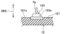
- FIG. 4 is a cross-sectional view showing a cross section taken along the line IV-IV in FIG. 2 in the first embodiment, and is a view showing a footwear detection switch for a floor mat.
- 16 of 8th Embodiment it is the figure which showed the order of the heating amount of the induction heating coil switched whenever a detector operation is made. In other embodiment, it is the figure which showed the 1st modification of the marker provided in the floor mat of 1st Embodiment. In other embodiment, it is the figure which showed the 2nd modification of the marker provided in the floor mat of 1st Embodiment.
- FIG. 1 is a cross-sectional view of a floor mat 12 included in the heating device 10 of the present embodiment, and shows a state in which a shoe 72 that is footwear for an occupant 70 is placed on the floor mat 12.
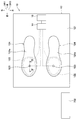
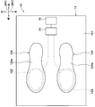
- 2 is an arrow view of the floor mat 12 viewed from the direction II in FIG. 1, that is, the floor mat 12 viewed from above the vehicle.
- FIG. 1 indicates the direction of the vehicle 69 (see FIG. 5) on which the heating device 10 is mounted. That is, the arrow DR1 in FIG. 1 indicates the vehicle longitudinal direction DR1, and the arrow DR2 indicates the vehicle vertical direction DR2. 2 indicates the vehicle width direction DR3 (that is, the vehicle left-right direction DR3). In FIG. 2, the feet 701 and shoes 72 of the occupant 70 are not shown. In addition, the occupant 70 using the heating device 10 is not limited to the driver, but the occupant 70 shown in FIG.
- the heating device 10 is a vehicle heating device provided in the vehicle 69. As shown in FIGS. 1 and 2, the heating device 10 includes a floor mat 12, a control unit 14, and a power supply device 16.
- the floor mat 12 of the heating device 10 is a sheet-like object installed on the floor surface 74a of the passenger compartment, and is disposed at a location that becomes a foot of the occupant 70.
- the floor mat 12 is a footwear placement section on which shoes 72 that are footwear of the occupant 70 are placed in the vehicle interior.
- the vehicle bottom 74 which is the floor panel of the vehicle body, constitutes the floor of the vehicle compartment
- the surface on the vehicle compartment side of the vehicle bottom 74 is the floor surface 74a of the vehicle compartment.
- the floor surface 74 a is covered with a vehicle carpet 76, and the floor mat 12 is laid on the vehicle carpet 76. That is, the floor mat 12 is disposed via the vehicle carpet 76 with respect to the floor surface 74a of the passenger compartment.
- the floor mat 12 includes a mat body 121, an induction heating coil 122, and a footwear detection switch 123.
- the mat body 121 is made of rubber and has a sheet shape.
- the induction heating coil 122 of the floor mat 12 When the induction heating coil 122 of the floor mat 12 is energized, the thin heating member 724 provided on the shoe sole 721 of the shoe 72 of the occupant 70 is heated by electromagnetic induction.
- the induction heating coil 122 is provided within the thickness of the mat body 121.
- the induction heating coil 122 is a coil in which a conductive metal member such as a copper wire is formed.
- the power supply device 16 including a power supply circuit for supplying power is electrically connected to the induction heating coil 122 via the control unit 14.
- an alternating voltage having a predetermined frequency for example, 25 kHz
- an alternating current flows through the induction heating coil 122 as controlled by the control unit 14.
- the control unit 14 controls the power supply device 16 so that a constant voltage (for example, 48 V) is applied to the induction heating coil 122.
- the induction heating coil 122 is provided in total, one for the left foot of the occupant 70 and one for the right foot.
- the left foot induction heating coil 122 and the right foot induction heating coil 122 are connected to the power supply device 16 in parallel.
- the shoe 72 of the occupant 70 includes a shoe sole 721 that constitutes the bottom of the shoe 72 and touches the ground (that is, the footwear sole 721), an upper portion 722 that wraps around the foot 701 of the occupant 70, A floor 723 and a heating member 724 are provided.
- the upper 722 is made of, for example, leather or synthetic leather.
- the shoe sole 721 is made of, for example, resin or rubber.
- the insole 723 of the shoe 72 is made of rubber, for example, and is provided inside the shoe 72. That is, the shoe insole 723 is laid over the entire bottom surface in the internal space of the shoe 72 into which the foot 701 of the occupant 70 is inserted.
- the heating member 724 is made of a metal foil such as aluminum.
- the thickness of the heating member 724 is, for example, about 25 ⁇ m.
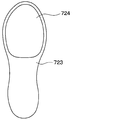
- FIG. 3 is an external view showing the insole 723 and the heating member 724 extracted. As shown in FIGS. 3 and 1, the heating member 724 is bonded and fixed to a surface of the shoe insole 723 that comes into contact with the sole of the occupant 70. Therefore, when the occupant 70 wears the shoes 72, the heating member 724 comes into contact with the foot 701 of the occupant 70.
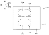
- the mat body 121 of the floor mat 12 is provided with a marker 124 as a mark for the occupant 70.
- the marker 124 is a footrest marker, and is printed, for example, on the surface 121a of the mat body 121 on which the shoe 72 is placed (that is, the placement portion surface 121a).
- the marker 124 indicates the position where the shoe 72 is placed when the occupant 70 needs to heat the shoe 72.
- the marker 124 indicates the position of the shoe 72 where the induction heating coil 122 can heat the heating member 724 of the shoe 72, that is, the heatable position in the floor mat 12.
- the marker 124 indicates a shoe placement region 124 a that is a partial region of the surface 121 a of the mat body 121.
- the marker 124 is configured by a figure that matches the shape of the shoe sole 721 of the shoe 72.
- the induction heating coil 122 is within the range occupied by the shoe placement region 124a in the surface direction along the surface 121a of the floor mat 12.
- the entire induction heating coil 122 is within the range occupied by the shoe placement region 124a in the surface direction. Therefore, when the shoe 72 is placed on the floor mat 12 according to the marker 124, the heating member 724 included in the shoe 72 is induction-heated by the induction heating coil 122 of the floor mat 12, and then the induction heating coil. It is arranged sufficiently close to 122.
- the footwear detection switch 123 is a detector that detects that the shoe 72 is placed at a heatable position indicated by the marker 124 on the floor mat 12.
- the footwear detection switch 123 functions as a foot heating switch that switches on / off of heating in the shoe 72, that is, on / off of heating in the shoe at the foot of the occupant 70.
- the footwear detection switch 123 is disposed inside an induction heating coil 122 wound as an electromagnetic coil.
- the footwear detection switch 123 is disposed within a range occupied by the shoe placement region 124 a in the surface direction along the surface 121 a of the floor mat 12.
- the footwear detection switch 123 is a push button switch, and includes an operation unit 123 a that is pushed by a shoe 72.
- the operation portion 123a protrudes upward from the surface 121a of the mat body 121 and is biased upward. And if the operation part 123a receives the press load Fp more than a predetermined load threshold value from the upper side, it will be pushed down by the press load Fp, and the footwear detection switch 123 will be in an ON state.
- the predetermined load threshold is, for example, that the footwear detection switch 123 is turned on by the weight of the shoe 72, while the footwear detection switch 123 is not turned on by the weight of a lightweight article such as a coin or can that is lighter than the shoe 72. Thus, it is experimentally set in advance.
- the footwear detection switch 123 is turned on when the shoe 72 is placed on the footwear detection switch 123. More specifically, the footwear detection switch 123 is turned on by being pressed by the shoe 72 placed on the footwear detection switch 123. And if the state by which the operation part 123a is pushed down is maintained, the ON state of the footwear detection switch 123 will also be maintained.
- the footwear detection switch 123 is turned off when the pressing load Fp pushing the operation unit 123a is less than a predetermined load threshold or when the operation unit 123a is not pressed and the footwear detection switch 123 is released. Accordingly, the footwear detection switch 123 changes from the on state to the off state when the shoe 72 placed on the footwear detection switch 123 is not placed.
- the footwear detection switch 123 is configured such that when the occupant 70 puts the shoe 72 on the heatable position indicated by the marker 124, the footwear detection switch 123 is switched from the off state to the on state by its own weight. Detection signals indicating that the footwear detection switch 123 is on or off are sequentially acquired by the control unit 14.
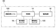
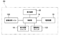
- FIG. 5 is a block configuration diagram showing an electrical configuration of the heating apparatus 10.
- the power supply device 16 illustrated in FIG. 5 is configured as an AC signal generation source that generates an AC signal having a constant voltage (for example, 48 V) and a predetermined frequency (for example, 25 kHz). Then, the power supply device 16 supplies power to the induction heating coil 122.
- a constant voltage for example, 48 V
- a predetermined frequency for example, 25 kHz
- the power supply device 16 operates or stops according to a signal input from the control unit 14. That is, the control unit 14 controls on / off of power supply from the power supply device 16 to the induction heating coil 122.
- the control unit 14 in FIG. 5 is an electronic control device composed of a microcomputer including a CPU, a ROM, a RAM, and the like (not shown). Signals from sensors connected to the control unit 14 are sequentially input to the control unit 14.
- the heating device 10 has a shoe heating switch 18, and a switching signal of the shoe heating switch 18 is sequentially input to the control unit 14.
- the shoe heating switch 18 is a power operation switch that the occupant 70 operates to switch the power supply device 16 on and off.
- the in-shoe heating switch 18 is provided, for example, in a part of an instrument panel in the passenger compartment so that the occupant 70 can easily operate the switch.
- the power supply device 16 when the power supply device 16 is turned on, that is, when the power supply device 16 is in a state where power can be supplied, the occupant 70 switches the shoe heating switch 18 to the on state. Conversely, when the power supply device 16 is turned off, that is, when the power supply device 16 is not supplied with power, the occupant 70 switches the shoe heating switch 18 to the off state.
- the induction heating coil 122 and the power supply device 16 are connected to the control unit 14.
- the control unit 14 controls power supply for turning on and off the power supply device 16 based on a switching signal from the shoe heating switch 18 and coil energization control for permitting or cutting off power supply from the power supply device 16 to the induction heating coil 122. And so on.
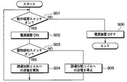
- the control process shown in FIG. 6 is executed.
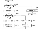
- FIG. 6 is a flowchart showing a control process executed by the control unit 14. For example, when the ignition switch of the vehicle 69 is turned on from off, the control unit 14 starts the control process of FIG. 6 and periodically repeats the control process of FIG.
- the control unit 14 executes the control processing of FIG. 6 independently and in parallel with each other in order to control one and the other of the two sets. Since the control processing of FIG. 6 is similarly executed for one of the two sets and the other, the control processing for one of the two sets will be described below, and the description for the other control processing will be omitted. To do.
- the control unit 14 first determines whether or not the shoe heating switch 18 is in an on state in step S01. If it is determined in step S01 that the shoe heating switch 18 is in the on state, the process proceeds to step S02. On the other hand, if it is determined that the shoe heating switch 18 is not in the on state, that is, if it is determined that the shoe heating switch 18 is in the off state, the process proceeds to step S06.
- step S02 the control unit 14 brings the power supply device 16 into an operating state. That is, the power supply device 16 is brought into a state where power can be supplied. If the power supply device 16 is already in operation, the control unit 14 continues it. After step S02, the process proceeds to step S03.
- step S03 the control unit 14 determines whether or not the footwear detection switch 123 is on. If it is determined in step S03 that the footwear detection switch 123 is on, the process proceeds to step S04. On the other hand, if it is determined that the footwear detection switch 123 is not in the on state, that is, if it is determined that the footwear detection switch 123 is in the off state, the process proceeds to step S05.
- the footwear detection switch 123 is released, and the footwear detection switch 123 changes from the on state to the off state.
- step S04 the control unit 14 permits power supply from the power supply device 16 to the induction heating coil 122.
- the power of the power supply device 16 is supplied to the induction heating coil 122 in step S04. If the power of the power supply device 16 has already been supplied to the induction heating coil 122, it continues.
- the induction heating coil 122 is energized (in other words, transmitted) when the footwear detection switch 123 is turned on. Thereby, for example, a high frequency current having a predetermined frequency flows in the induction heating coil 122, and a high frequency magnetic field corresponding to the high frequency current is generated in the induction heating coil 122. Although the induction heating coil 122 does not contact the heating member 724 of the shoe 72, an eddy current is generated in the heating member 724 near the induction heating coil 122 so as to cancel the high-frequency magnetic field.
- the heating member 724 when the electric resistance of the heating member 724 is R and the eddy current is I, the heating member 724 generates Joule heat having a magnitude of “R ⁇ I 2 ” due to the eddy current.
- the Joule heat generated by the heating member 724 is directly transmitted to the foot 701 of the occupant 70 by heat conduction in the shoe 72, so that the occupant 70 immediately feels a sense of heating even if the power consumption of the induction heating coil 122 is small. Can be obtained.
- step S05 the control unit 14 stops the power supply from the power supply device 16 to the induction heating coil 122. If the power supply has already been stopped, it continues. As described above, the control unit 14 receives the detection signal from the footwear detection switch 123 and turns on / off the alternating current to the induction heating coil 122 based on the detection signal.
- step S06 the control unit 14 stops the power supply device 16. That is, the power supply device 16 is not supplied with power. If the power supply device 16 is already stopped, the control unit 14 continues it. When the power supply device 16 is in a stopped state, power is not supplied to the induction heating coil 122 regardless of whether the footwear detection switch 123 is on or off. After step S04, step S05, or step S06, the process proceeds to step S01.
- the marker 124 is provided on the floor mat 12 as shown in FIGS. Then, the marker 124 indicates a heatable position of the shoe 72 where the induction heating coil 122 can heat the heating member 724 of the shoe 72 on the floor mat 12. Thereby, the position of the shoe 72 that can be heated by the electromagnetic induction by the heating device 10 (that is, the heatable position) can be clearly shown to the occupant 70.
- the heating member 724 of the shoe 72 can be guided to a position where induction heating occurs. Then, the heating of the feet of the occupant 70, that is, the heating in the shoes, can be efficiently performed.
- the marker 124 indicates the shoe placement region 124 a that is a partial region of the surface 121 a of the mat body 121.
- at least a part of the induction heating coil 122 is within the range occupied by the shoe mounting region 124a in the surface direction along the surface 121a of the floor mat 12. Therefore, the position where the shoe 72 can be heated can be clearly and easily shown to the passenger 70.
- the floor mat 12 is provided with the induction heating coil 122 and the footwear detection switch 123.
- the footwear detection switch 123 is turned on when the shoe 72 of the occupant 70 is placed on the footwear detection switch 123. Specifically, the footwear detection switch 123 is turned on by its own weight. In this way, when the footwear detection switch 123 is turned on, the induction heating coil 122 is energized.
- the footwear detection switch 123 is turned on by its own weight. Therefore, when the footwear detection switch 123 is turned on, the induction heating coil 122 is energized.
- the footwear detection switch 123 when the occupant 70 desires to heat the shoes 72, the occupant 70 can easily turn on the footwear detection switch 123 by stepping on the footwear detection switch 123 with the shoes 72. Therefore, energization of the induction heating coil 122 is turned on / off according to the necessity of heating the shoe 72, and unnecessary power consumption of the heating device 10 can be avoided.
- the energization of the induction heating coil 122 is executed by the weight of the shoe 72. Then, by setting a predetermined load threshold value of the footwear detection switch 123, the heating device 10 is prevented from malfunctioning due to the weight of a lightweight article such as a coin or a can. Therefore, it is possible to efficiently heat the feet or feet and contribute to energy saving.
- the footwear detection switch 123 is disposed within the range occupied by the shoe placement region 124a in the surface direction along the surface 121a of the floor mat 12. Accordingly, if the shoe 72 is placed on the shoe placement region 124a, the shoe 72 is placed on the footwear detection switch 123 accordingly.
- FIG. 7 is an arrow view of the floor mat 12 of the present embodiment as viewed from the II direction of FIG. 1, and corresponds to FIG. 2 of the first embodiment.
- the floor mat 12 has a mat body 121 and an induction heating coil 122, but does not have a footwear detection switch 123. This embodiment is different from the first embodiment in this point.
- step S02 or step S06 is followed by step S01.
- the heating member 724 of the shoe 72 is heated by the induction heating coil 122 when the shoe 72 is placed on the floor mat 12 at the heatable position indicated by the marker 124.
- the shoes are heated.
- FIG. 9 is an arrow view of the floor mat 12 of the present embodiment as viewed from the direction II in FIG. 1, and corresponds to FIG. 2 of the first embodiment. As shown in FIG. 9, in this embodiment, the marker 124 of FIG. 2 is not provided. This embodiment is different from the first embodiment in this point.
- one induction heating coil 122 and one footwear detection switch 123 are provided. Although there is one induction heating coil 122 of this embodiment, the left and right shoes 72 placed on the floor mat 12 can be heated simultaneously. Therefore, the induction heating coil 122 extends over the entire width in which the left and right shoes 72 are placed in the vehicle width direction DR3.
- the footwear detection switch 123 may be provided at a position where one of the left and right shoes 72 is placed. In the present embodiment, the footwear detection switch 123 is provided at a position where the right foot shoe 72 is placed.
- control process executed by the control unit 14 is the same as that in the first embodiment, and is as shown in the flowchart of FIG.
- FIG. 10 is a block configuration diagram showing an electrical configuration of the heating apparatus 10 of the present embodiment, and corresponds to FIG. 5 of the first embodiment.
- the footwear detection switch 123 is not provided as in the second embodiment.
- a signal from the seat belt wearing detection switch 20 of the vehicle 69 is input to the control unit 14 of the heating device 10 of the present embodiment.
- the vehicle 69 on which the heating device 10 of this embodiment is mounted has a plurality of seats on which occupants are seated.
- the plurality of seats include, for example, the driver seat 78 of FIG.
- Each of the plurality of seats is provided with a seat belt and a seat belt wearing detection switch 20. That is, the seat belt wearing detection switch 20 is provided by the number of a plurality of seats.
- the floor mat 12 is the same as that of the second embodiment, it is shown in FIG.
- the floor mat 12 is disposed at the foot portion of each of the plurality of seats in the vehicle interior. In short, if one of the plurality of seats is a predetermined seat, the floor mat 12 is provided at a location corresponding to the predetermined seat.
- the seat belt wearing detection switch 20 is a switch that detects that the occupant 70 wears the seat belt in a predetermined seat provided with the seat belt wearing detection switch 20 among the plurality of seats. Therefore, the seat belt wearing detection switch 20 functions as an occupant detection unit that detects that the occupant 70 is in the predetermined seat.
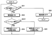
- FIG. 11 is a flowchart showing a control process executed by the control unit 14 of the present embodiment, and corresponds to FIG. 6 of the first embodiment.
- the control process of FIG. 11 is executed in the same manner as the control process of FIG. That is, for example, when the ignition switch of the vehicle 69 is turned on from off, the control unit 14 starts the control process of FIG. 11 and periodically executes the control process of FIG.
- the control processing of FIG. 11 is executed independently and in parallel for each seat.
- shoe heating is performed in a predetermined seat which is one of a plurality of seats.
- steps S01, S02, S04, S05, and S06 in FIG. 11 are the same as those in FIG. 6, description of those steps is omitted.
- step S03 of FIG. 6 is replaced with step S031.
- step S02 is followed by step S031.
- the control unit 14 determines whether the seat belt wearing detection switch 20 detects that the occupant 70 is in a predetermined seat. Specifically, when the wearing of the seat belt is detected by the seat belt wearing detection switch 20 in the predetermined seat, the control unit 14 determines that the occupant 70 is in the predetermined seat. On the other hand, when wearing of the seat belt is not detected by the seat belt wearing detection switch 20, the control unit 14 determines that the occupant 70 is not in the predetermined seat.
- step S031 When it is determined in step S031 that the occupant 70 is in the predetermined seat, the process proceeds to step S04. That is, when it is detected by the seat belt wearing detection switch 20 that the occupant 70 is in the predetermined seat, the control unit 14 energizes the induction heating coil 122 in the same manner as in the first embodiment in step S04.
- step S031 determines whether the occupant 70 is in the predetermined seat. If it is determined in step S031 that the occupant 70 is not in the predetermined seat, the process proceeds to step S05. That is, when it is detected by the seatbelt wearing detection switch 20 that the occupant 70 is not in the predetermined seat, the control unit 14 stops energizing the induction heating coil 122 in the same manner as in the first embodiment in step S05. To do.
- the vehicle 69 detects a seat belt wearing detection switch as an occupant detection unit that detects the presence of an occupant in the predetermined seat. 20. Further, the floor mat 12 is provided at a position corresponding to the position of the predetermined seat in the vehicle interior. The control unit 14 energizes the induction heating coil 122 when the seat belt wearing detection switch 20 detects that the occupant 70 is in the predetermined seat.
- the induction heating coil 122 is executed when the occupant 70 is in the predetermined seat, and unnecessary power consumption of the heating device 10 can be avoided.
- the shoe heating switch 18 When the shoe heating switch 18 is on and the occupant 70 is wearing a seat belt in a predetermined seat, the occupant 70 places the shoe 72 at a heatable position indicated by the marker 124 of the floor mat 12. For example, in-shoe heating by induction heating is performed.
- FIG. 12 is a block configuration diagram showing an electrical configuration of the heating apparatus 10 of the present embodiment, and corresponds to FIG. 5 of the first embodiment.
- the heating device 10 of this embodiment includes a display device 22.
- the display device 22 is electrically connected to the control unit 14.
- the present embodiment is different from the first embodiment in these points.
- the display device 22 shown in FIG. 12 displays that the induction heating coil 122 is energized.
- the display device 22 is a notification device that visually notifies the occupant 70 that the induction heating coil 122 is energized.
- the display device 22 is an indicator composed of a light emitting diode or the like, and is provided, for example, at a part of an instrument panel in a vehicle cabin so that the occupant 70 can easily see.
- the display device 22 is turned on while the induction heating coil 122 is energized and is turned off while the induction heating coil 122 is not energized according to the control signal from the control unit 14.
- the display device 22 may display whether the induction heating coils 122 are energized or not energized. Alternatively, the display device 22 displays that the current is energized when any one of the plurality of induction heating coils 122 is energized, and displays that is not energized when all the induction heating coils 122 are deenergized. You may go.
- the display device 22 is supplied with power from, for example, the power supply device 16. Therefore, for example, when the power supply device 16 is stopped in step S06 of FIG. 13 described later, the display device 22 is turned off.
- FIG. 13 is a flowchart showing a control process executed by the control unit 14 of the present embodiment, and corresponds to FIG. 6 of the first embodiment.
- the control process of FIG. 13 is executed in the same manner as the control process of FIG. That is, for example, when the ignition switch of the vehicle 69 is turned on from off, the control unit 14 starts the control process of FIG. 13 and periodically executes the control process of FIG.
- steps S01 to S06 in FIG. 13 are the same as those in FIG. 6, description of those steps is omitted.
- step S07 is provided between step S03 and step S04
- step S08 is provided between step S03 and step S05.
- the control process of FIG. 13 is different from the control process of FIG. 6 in that steps S07 and S08 are provided.
- step S03 determines in step S03 that the footwear detection switch 123 is on
- step S07 determines that the footwear detection switch 123 is off
- step S08 proceeds to step S08.
- step S07 the control unit 14 causes the display device 22 to perform a display indicating that the induction heating coil 122 is energized, that is, a display during energization (in other words, a display during power transmission). If the display during energization has already been performed, it is continued. The display during energization is, for example, that the display device 22 is turned on. After step S07, the process proceeds to step S04.
- step S08 the control unit 14 causes the display device 22 to perform a display indicating that the induction heating coil 122 is not energized, that is, a display during de-energization (in other words, a display during non-power transmission). If the non-energized display has already been performed, it is continued. The non-energized display is, for example, that the display device 22 is turned off. After step S08, the process proceeds to step S05.
- the heating device 10 includes the display device 22 that displays that the induction heating coil 122 of the floor mat 12 is energized. Therefore, it is possible to make the occupant 70 recognize that the shoe 72 of the occupant 70 is heated by appealing to the sight of the occupant 70.
- this embodiment is a modification based on the first embodiment, it is possible to combine this embodiment with each of the second to fourth embodiments described above.
- the arrangement location of the display device 22 is different from that of the fifth embodiment. Except for this, this embodiment is the same as the fifth embodiment.
- the display device 22 is arranged at a place where the marker 124 is provided in the floor mat 12 shown in FIG.
- the display device 22 includes a plurality of light emission indicators that are continuous along the outer edge of the marker 124. Thereby, when the display device 22 is turned on, the marker 124 appears to emit light. That is, it is possible to show the occupant 70 that the marker 124 provided on the floor mat 12 has a function as the display device 22.
- FIG. 14 is a block configuration diagram showing an electrical configuration of the heating apparatus 10 of the present embodiment, and corresponds to FIG. 5 of the first embodiment.
- the heating device 10 of this embodiment includes a speaker 26 that is a sound generator.
- the speaker 26 is electrically connected to the control unit 14.
- the present embodiment is different from the first embodiment, and the other points are the same as those of the first embodiment.
- the speaker 26 shown in FIG. 14 is a notification device that audibly notifies the occupant 70 that the induction heating coil 122 is energized.
- the speaker 26 is provided, for example, in a part of an instrument panel in the passenger compartment so that the passenger 70 can easily hear the sound from the speaker 26.
- the speaker 26 emits sound according to a control signal from the control unit 14.
- the speaker 26 is supplied with power from, for example, the power supply device 16. Therefore, for example, when the power supply device 16 is stopped in step S06 of FIG. 15 described later, the speaker 26 does not emit sound.
- FIG. 15 is a flowchart showing a control process executed by the control unit 14 of the present embodiment, and corresponds to FIG. 6 of the first embodiment.
- the control process of FIG. 15 is executed in the same manner as the control process of FIG. That is, for example, when the ignition switch of the vehicle 69 is turned from OFF to ON, the control unit 14 starts the control process of FIG. 15 and periodically executes the control process of FIG.
- step S09 is provided between step S03 and step S04, and step S10 is provided between step S03 and step S05.
- the control process of FIG. 15 differs from the control process of FIG. 6 in that these steps S09 and S10 are provided.
- step S03 when the control unit 14 determines in step S03 that the footwear detection switch 123 is on, the process proceeds to step S09. On the other hand, if the control unit 14 determines that the footwear detection switch 123 is off, the process proceeds to step S10.
- step S09 the control unit 14 notifies the occupant 70 by sound from the speaker 26 that the induction heating coil 122 is energized. Specifically, the control unit 14 causes the speaker 26 to generate a predetermined sound indicating that the induction heating coil 122 is energized, that is, an energization notification sound. For example, the energization notification sound may be continuously generated while the induction heating coil 122 is energized, or only generated when the induction heating coil 122 is switched from non-energized to energized. Also good.
- step S09 the process proceeds to step S04.
- step S10 the control unit 14 notifies the occupant 70 with a sound from the speaker 26 that the induction heating coil 122 is not energized. Specifically, the control unit 14 causes the speaker 26 to generate a predetermined sound indicating that the induction heating coil 122 is not energized, that is, a de-energization notification sound.
- the non-energization notification sound is different from the energization notification sound due to, for example, a different melody or tone color.
- the non-energization notification sound may be continuously generated while the induction heating coil 122 is not energized, or only generated when the induction heating coil 122 is switched from being energized to being de-energized. There may be. After step S10, the process proceeds to step S05.
- the heating device 10 includes the speaker 26 that audibly notifies the occupant 70 that the induction heating coil 122 is energized. Therefore, it is possible for the occupant 70 to recognize that the shoe 72 of the occupant 70 is heated by appealing to the hearing of the occupant 70. For example, the occupant 70 who is driving the vehicle can know that the induction heating coil 122 is energized without changing the line of sight.
- this embodiment is a modification based on the first embodiment, it is possible to combine this embodiment with each of the above-described second to sixth embodiments.
- the speaker 26 of this embodiment may be used together with the display device 22 of the fifth and sixth embodiments.
- the heating amount Wc of the induction heating coil 122 with respect to the heating member 724 is switched while the induction heating coil 122 is energized.
- the present embodiment is different from the first embodiment, and the other points are the same as those of the first embodiment.
- step S03 in FIG. 6 the control process in FIG. 16 is started. Then, the control unit 14 executes the control process of FIG. 16 in parallel with the control process of FIG. 6, and continues the control process of FIG. 16 while continuing to determine that the footwear detection switch 123 is in the ON state. continue. On the other hand, if the control unit 14 determines in step S01 in FIG. 6 that the in-shoe heating switch 18 is in the off state, or if it is determined in step S03 that the footwear detection switch 123 is in the off state, 16 control processing is stopped.
- step S03 of FIG. 6 when it determines with the footwear detection switch 123 being an ON state, even if the footwear detection switch 123 is instantaneously switched from an ON state to an OFF state, it is said that it is an ON state.
- the determination in step S03 is continued. This is because the instantaneous switching to the OFF state is an operation included in the detector operation described later.
- step S001 the control unit 14 performs a predetermined detector operation on the footwear detection switch 123 when the footwear detection switch 123 which is a detector is in an ON state. Determine whether it was done.
- the detector operation is, for example, a momentary off operation in which the footwear detection switch 123 is instantaneously switched from the on state to the off state and returned to the on state again.
- Whether or not the off state is instantaneous is whether or not the time interval from the time when the footwear detection switch 123 is switched from the on state to the off state until the time when the footwear detection switch 123 is returned to the on state is equal to or less than a predetermined determination time. It is judged by.
- step S001 If it is determined in step S001 that the detector operation is performed on the footwear detection switch 123 when the footwear detection switch 123 is in the ON state, the process proceeds to step S002. On the other hand, when it is determined that the detector operation is not performed on the footwear detection switch 123, the determination in step S001 is performed again.
- step S002 the control unit 14 changes the heating amount Wc of the induction heating coil 122 for the heating member 724 with respect to that before the detector operation is performed.
- the unit of the heating amount Wc is, for example, “W”, and the heating amount Wc is increased or decreased according to the magnitude of the current passed through the induction heating coil 122.
- step S001 every time it is determined in step S001 that the detector operation has been performed, the control unit 14 switches the heating amount Wc of the induction heating coil 122 step by step each time the detector operation is performed.
- the weak, medium, and strong heating amounts Wc are predetermined in the order of the heating amount Wc of “weak ⁇ medium ⁇ strong”.
- the heater off in FIG. 17 is that the heating amount Wc is zero, that is, energization of the induction heating coil 122 is stopped.
- the initial value of the heating amount Wc is a weak heating amount Wc in the present embodiment. Therefore, for example, when the determination in step S03 in FIG. 6 is switched from the determination that the footwear detection switch 123 is in the off state to the determination that the footwear detection switch 123 is in the on state, the heating amount of the induction heating coil 122 is determined in step S04. First, Wc becomes a weak heating amount Wc.
- the control unit 14 switches the heating amount Wc of the induction heating coil 122 in the order of weak, medium, strong, and heater off. Further, when the detector operation is performed when the switching of the heating amount Wc in FIG. 17 is the heater off, the control unit 14 returns the heating amount Wc of the induction heating coil 122 to the weak heating amount Wc.
- the control unit 14 changes the heating amount Wc of the induction heating coil 122 for the heating member 724 with respect to before the detector operation is performed. Accordingly, the occupant 70 can adjust the heating amount Wc by the operation of the foot 701.
- the detector operation determined in step S001 of FIG. 16 is, for example, the moment when the footwear detection switch 123 is instantaneously switched from the on state to the off state and then returned to the on state again. It is an off operation. Therefore, the occupant 70 can adjust the heating amount Wc by a simple operation of the foot 701.
- this embodiment is a modification based on the first embodiment, it is possible to combine this embodiment with each of the third and fifth to seventh embodiments described above.
- the mat body 121 of the floor mat 12 is made of rubber, but may be made of other insulating materials such as cloth.
- the heating member 724 contacts the foot 701 of the occupant 70, but if the heat of the induction heated heating member 724 is transmitted to the foot 701 of the occupant 70, the heating member 724 There is no need to contact the foot 701.
- the marker 124 of the floor mat 12 is configured by a figure that matches the shape of the sole 721 of the shoe 72, as shown in FIG. There is no limitation on the shape. The same applies to the second and fourth to eighth embodiments.
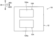
- the marker 124 of the floor mat 12 may have a frame shape as shown in FIG. 18, or may have a rectangular shape as shown in FIG.
- the color in the shoe mounting region 124a shown in FIG. 2 and FIG. 19 is configured to be different from the surrounding color of the shoe mounting region 124a, thereby forming a marker 124 as a mark. May be.
- the length of the hair implanted in the shoe placement region 124a shown in FIGS. 2 and 19 is around the shoe placement region 124a.
- the length may be different for the hair that has been implanted.
- the marker 124 as a mark is formed by the difference in hair length.
- the length of the hair in the shoe placement region 124a may be shorter than the hair around the shoe placement region 124a.
- hair may be planted around the shoe placement area 124a, but not in the shoe placement area 124a, and the shoe placement area 124a may function as a mudguard.
- the predetermined load threshold value for turning on the footwear detection switch 123 is, for example, that the footwear detection switch 123 is turned on by the weight of the shoe 72. This is experimentally set in advance. However, this is an example, and the predetermined load threshold is that the footwear detection switch 123 is not turned on by the weight of the shoe 72 alone but the footwear detection switch 123 is turned on by the weight of the foot 701 of the shoe 72 and the passenger 70. It can be considered that it is set to be.
- the footwear detection switch 123 is a push button switch, but may be another type of switch or sensor.
- the shoe heating switch 18 for switching between the operating state and the stopped state of the power supply device 16 is provided, but the shoe heating switch 18 may be omitted. In the case where the shoe heating switch 18 is not provided, for example, the power supply device 16 is activated when the ignition switch of the vehicle 69 is turned on.
- the seatbelt wear detection switch 20 functions as an occupant detection unit that detects that the occupant 70 is in a predetermined seat provided with the seatbelt wear detection switch 20.
- the occupant detection unit may be a seating sensor that reacts to the weight of the seated occupant or a camera that observes the interior of the vehicle, instead of the seat belt wearing detection switch 20.
- the display device 22 is an indicator composed of, for example, a light emitting diode, but may be composed of a liquid crystal display or the like. Further, the display device 22 may be provided integrally with another display unit included in the vehicle interior air conditioner. Further, the display device 22 may not be provided on the instrument panel.
- the display device 22 is turned off while the induction heating coil 122 is not energized, but this is an example.
- the display device 22 is turned on even when the induction heating coil 122 is not energized, and the manner in which the display device 22 is turned on while the induction heating coil 122 is not energized (for example, emission color or brightness) is determined by the induction heating coil. It may be different as compared with 122 during energization.
- the display device 22 is a separate object from the marker 124, but these may not be configured as separate objects.
- the display device 22 and the marker 124 may be configured as a single object having both the function of the display device 22 and the function of the marker 124.
- step S10 of FIG. 15 the control unit 14 generates a non-energization notification sound from the speaker 26, but this is an example.
- the control unit 14 stops the energization notification sound and generates a sound from the speaker 26 in step S10 of FIG. May not be generated.
- the predetermined detector operation determined in step S001 in FIG. 16 is performed again by switching the footwear detection switch 123 from the on state to the off state instantaneously.
- this is an instantaneous off operation, this is an example.
- the detector operation may not be a momentary off operation, or may be an operation in which the momentary off operation continues multiple times.
- the heating amount Wc of the induction heating coil 122 is switched in stages, and the induction heating coil 122 is also turned off, but this is an example.
- the heating amount Wc in FIG. 17 for example, there is no need to turn off the heater, and the heating amount Wc may not be a three-stage switching of weak, medium, and strong.
- the predetermined detector operation determined in step S001 of FIG. 16 is an operation on the footwear detection switch 123 of FIG. 2, but this is an example.
- another push button switch that is turned on simultaneously with the footwear detection switch 123 when the shoe 72 is placed on the footwear detection switch 123 is provided on the floor mat 12 in the vicinity of the footwear detection switch 123.
- the other push button switch and the footwear detection switch 123 constitute a detector provided on the floor mat 12, and the predetermined detector operation is an operation on the other push button switch. Also good.
- the control unit 14 is provided corresponding to the certain footwear detection switch 123. Only the heating amount Wc of the induction heating coil 122 may be switched.
- the induction heating coil 122, the footwear detection switch 123, and the marker 124 are provided on the floor mat 12, but are not limited to the floor mat 12, and are provided in other parts. There is no problem. That is, the footwear placement portion having the induction heating coil 122, the footwear detection switch 123, and the marker 124 is not limited to the floor mat 12, and the pedal 781 of FIG. May be the footrest 782 of FIG. By doing so, it is possible to provide the induction heating coil 122 at a practical location in the vehicle 69. This also applies to the second to fifth embodiments.
- the pedal 781 as the footwear placement section is an accelerator pedal in FIG. 1, it may be a brake pedal or a clutch pedal. More specifically, the footrest 782 is a footrest that is disposed at the foot portion of the driver's seat 78 and fixed to the vehicle bottom 74.
- the heating member 724 of the shoe 72 is made of a metal foil, but it may be made of a material other than the metal foil, such as a conductive metal wire.
- the heating member 724 to be induction-heated is provided on the shoe 72, but may be provided on other footwear such as sandals or socks.
- the induction heating coil 122 is provided corresponding to the position of the seat of the vehicle 69, but is not necessarily provided corresponding to the position of the seat of the vehicle 69. .
- the mark provided on the footwear placement portion is such that the induction heating coil heats the heating member in the footwear placement portion. Display the position of the possible footwear.
- the mark indicates a partial region on the surface of the placement unit.
- at least one part of the induction heating coil is in the range which the one part area
- the detector provided in the footwear placing portion is turned on when the footwear is placed on the detector.
- the induction heating coil is energized when the detector is turned on.
- the detector provided in the footwear mounting part will be in an ON state, when footwear is mounted on the detector.
- the induction heating coil is energized when the detector is turned on.
- the detector is further disposed within the range occupied by the partial area in the surface direction of the surface of the placement unit. Therefore, if the footwear is placed on the partial area, the footwear is placed on the detector accordingly.
- the controller controls the amount of heating of the induction heating coil with respect to the heating member when a predetermined detector operation is performed on the detector when the detector is on. Is changed with respect to before the detector operation is performed. Therefore, the occupant can adjust the heating amount by the operation of the foot.
- the detector operation is an operation in which the detector is instantaneously switched from the on state to the off state and then returned to the on state again, or an operation in which the instantaneous off operation continues. It is. Therefore, the occupant can adjust the heating amount by a simple foot motion.
- the vehicle has a predetermined seat on which the occupant is seated, and an occupant detection unit that detects the presence of the occupant in the predetermined seat.
- the footwear placement section is provided at a location corresponding to the position of the predetermined seat in the passenger compartment.
- a control part supplies with electricity to an induction heating coil, when it detects that a passenger
- the display device visually notifies the occupant that the induction heating coil is energized.
- the display apparatus is arrange
- the heating device includes a display device that displays that the induction heating coil is energized. Therefore, it is possible to make the occupant recognize that the occupant's shoes are heated by appealing to the sight of the occupant.
- the footwear placing portion is a floor mat installed on the floor surface of the passenger compartment, a pedal operated by an occupant, or a footwear fixed to the passenger compartment floor. It is a footrest. Therefore, it is possible to provide the induction heating coil at a practical place in the vehicle.
- the sound generator audibly informs the occupant that the induction heating coil is energized. Therefore, it is possible to make the occupant recognize that the footwear of the occupant is heated by appealing to the occupant's hearing.
Landscapes
- Engineering & Computer Science (AREA)
- Mechanical Engineering (AREA)
- Physics & Mathematics (AREA)
- Transportation (AREA)
- Thermal Sciences (AREA)
- Electromagnetism (AREA)
- Chemical & Material Sciences (AREA)
- Materials Engineering (AREA)
- General Induction Heating (AREA)
- Footwear And Its Accessory, Manufacturing Method And Apparatuses (AREA)
- Seats For Vehicles (AREA)
Abstract
加熱装置は、車両(69)に搭載される。そして、その加熱装置は、誘導加熱コイル(122)と、車室内で乗員(70)の履物(72)が載せられる履物載置部(12、781、782)に設けられた目印(124)とを備える。誘導加熱コイルは、履物載置部に設けられ、履物が有する加熱部材(724)を、通電されることで電磁誘導により加熱する。また、目印は、履物載置部において、誘導加熱コイルが加熱部材を加熱することができる履物の位置を表示する。
Description
本出願は、2016年3月25日に出願された日本特許出願番号2016-61962号に基づくもので、ここにその記載内容が参照により組み入れられる。
本開示は、乗員の履物を電磁誘導により加熱する加熱装置に関するものである。
この種の加熱装置のように履物を加熱する加熱装置が、例えば特許文献1に開示されている。この特許文献1に開示された加熱装置は、履物としてのスキー用具を外部から加熱するものである。具体的には、そのスキー用具の内部には保温部材とこの保温部材を加熱するための加熱部材とが設けられている。そして、特許文献1の加熱装置は、そのスキー用具の加熱部材を電磁誘導によって加熱する。
ところで、特許文献1の加熱装置が加熱する加熱対象はスキー用具であるが、発明者らは、その加熱対象を、車両の乗員が履く履物とすることを考えた。
しかし、車室内において、乗員の履物と加熱装置の誘導加熱コイルとの相対的な位置関係は、乗員の姿勢変化に伴って変化する。その一方で、加熱装置が履物を加熱する際には、その加熱装置は電磁誘導により履物を加熱するので、その履物は、車室内で或る程度限定された場所に配置される必要がある。従って、加熱可能な履物の位置が乗員にとって不明であるとすれば、乗員は、履物をその乗員の意思に従って加熱装置に加熱させることが困難である。
また、車両では、加熱装置が電磁誘導により加熱することが可能な範囲内に、乗員の履物ではなくコインや缶等の軽量金属物が入ってくることが想定される。そのような場合において、加熱装置がその軽量金属物を加熱したとすれば、加熱のためのエネルギが不必要に消費されることになる。発明者らの詳細な検討の結果、以上のようなことが見出された。
上記点に鑑みて、本開示は、加熱装置が電磁誘導により加熱することが可能な履物の位置を明瞭に示すことを第1の目的とする。また、本開示は、加熱装置の不必要な電力消費を回避することを第2の目的とする。
上記目的を達成するため、本開示の1つの観点による加熱装置は、車両に搭載される加熱装置であって、
車室内で乗員の履物が載せられる履物載置部に設けられ、履物が有する加熱部材を、通電されることで電磁誘導により加熱する誘導加熱コイルと、
履物載置部に設けられた目印とを備え、
その目印は、履物載置部において、誘導加熱コイルが加熱部材を加熱することができる履物の位置を表示する。
車室内で乗員の履物が載せられる履物載置部に設けられ、履物が有する加熱部材を、通電されることで電磁誘導により加熱する誘導加熱コイルと、
履物載置部に設けられた目印とを備え、
その目印は、履物載置部において、誘導加熱コイルが加熱部材を加熱することができる履物の位置を表示する。
これにより、加熱装置が電磁誘導により加熱することが可能な履物の位置を乗員に対し明瞭に示すことができる。
また、本開示のもう1つの観点による加熱装置は、車両に搭載される加熱装置であって、
車室内で乗員の履物が載せられる履物載置部に設けられ、履物が有する加熱部材を、通電されることで電磁誘導により加熱する誘導加熱コイルと、
履物載置部に設けられた検知器とを備え、
その検知器は、その検知器上に履物が載ることでオン状態になり、
誘導加熱コイルは、検知器がオン状態になった場合に通電される。
車室内で乗員の履物が載せられる履物載置部に設けられ、履物が有する加熱部材を、通電されることで電磁誘導により加熱する誘導加熱コイルと、
履物載置部に設けられた検知器とを備え、
その検知器は、その検知器上に履物が載ることでオン状態になり、
誘導加熱コイルは、検知器がオン状態になった場合に通電される。
これにより、乗員は、履物の加熱を欲する場合に履物で検知器を踏むなどして容易に検知器をオン状態にすることができる。従って、履物の加熱の必要性に応じて誘導加熱コイルの通電がオンオフされ、加熱装置の不必要な電力消費を回避することができる。
以下、図面を参照しながら、本開示の実施形態を説明する。なお、以下の各実施形態相互において、互いに同一もしくは均等である部分には、図中、同一符号を付してある。
(第1実施形態)
図1は、本実施形態の加熱装置10が有するフロアマット12の断面図であって、乗員70の履物である靴72がそのフロアマット12に載せられた様子を示した図である。また、図2は、図1におけるII方向からフロアマット12を見た矢視図、すなわち、フロアマット12を車両上方から見た図である。
図1は、本実施形態の加熱装置10が有するフロアマット12の断面図であって、乗員70の履物である靴72がそのフロアマット12に載せられた様子を示した図である。また、図2は、図1におけるII方向からフロアマット12を見た矢視図、すなわち、フロアマット12を車両上方から見た図である。
図1の各矢印DR1、DR2および図2のDR3は、加熱装置10が搭載された車両69(図5参照)の向きを示す。すなわち、図1の矢印DR1は車両前後方向DR1を示し、矢印DR2は車両上下方向DR2を示している。また、図2の矢印DR3は車両幅方向DR3(すなわち、車両左右方向DR3)を示している。なお、図2では、乗員70の足701および靴72の図示は省略されている。また、加熱装置10を利用する乗員70は運転者に限らないが、図1に示された乗員70は運転席78に着座した運転者である。
加熱装置10は、車両69に設けられる車両用加熱装置である。図1および図2に示すように、加熱装置10は、フロアマット12と制御部14と電源装置16を備えている。
加熱装置10のフロアマット12は、車室の床面74a上に設置されるシート状物であり、乗員70の足元となる箇所に配置されている。フロアマット12は、車室内で乗員70の履物である靴72が載せられる履物載置部である。具体的には、車体のフロアパネルである車両底部74が車室の床を構成しているので、その車両底部74の車室側の面が車室の床面74aとなっている。そして、その床面74a上は車両カーペット76で覆われ、フロアマット12はその車両カーペット76上に敷かれている。すなわち、フロアマット12は、車室の床面74aに対し車両カーペット76を介して配置されている。
フロアマット12は、マット本体121と誘導加熱コイル122と履物検知スイッチ123とを有している。そのマット本体121はゴム製であり、シート形状を成している。
フロアマット12の誘導加熱コイル122は通電されることで、乗員70の靴72の靴底721に設けられた薄肉の加熱部材724を電磁誘導により加熱する。この誘導加熱コイル122は、マット本体121の厚み内に設けられている。誘導加熱コイル122は、例えば銅線材などの導電性金属部材がコイル状に形成されたものである。
誘導加熱コイル122には、電力を供給する電源回路を含む電源装置16が制御部14を介して電気的に接続されている。これにより、誘導加熱コイル122には、所定周波数(例えば、25kHz)の交流電圧が印加されるようになっている。そして、誘導加熱コイル122には、交流電流が制御部14により制御されて流れる。例えば、制御部14は、誘導加熱コイル122に通電する場合には、その誘導加熱コイル122に一定電圧(例えば、48V)がかかるように電源装置16を制御する。
この誘導加熱コイル122は、乗員70の左足用として1つ、右足用として1つ、合計2つ設けられている。そして、左足用の誘導加熱コイル122と右足用の誘導加熱コイル122とは、電源装置16に対し互いに並列に接続されている。
乗員70の靴72は、図1に示すように、靴72の底部を構成し地面に接する靴底721(すなわち、履物底721)と、乗員70の足701を包み込む甲部722と、靴中敷723と、加熱部材724とを有している。その甲部722は、例えば、皮または合成皮革等により構成されている。また、靴底721は、例えば、樹脂またはゴム等により構成されている。
靴72の靴中敷723は例えばゴム製であり、靴72の内部に設けられている。すなわち、靴中敷723は、乗員70の足701が挿入される靴72の内部空間における底面の全体にわたって敷かれている。
加熱部材724は、アルミニウム等の金属箔で構成されている。その加熱部材724の厚みは例えば25μm程度である。図3は、靴中敷723および加熱部材724を抜粋して示した外観図である。その図3および図1に示すように、加熱部材724は、靴中敷723のうち乗員70の足裏と接触する面に接着固定されている。従って、乗員70が靴72を履いた場合には、加熱部材724は乗員70の足701に接触する。
図1および図2に示すように、フロアマット12のマット本体121には、乗員70に対する目印としてのマーカ124が設けられている。このマーカ124は、足載せマーカであり、靴72が載せられるマット本体121の表面121a(すなわち、載置部表面121a)に例えば印刷されている。マーカ124は、乗員70が靴72の加熱を必要とした際にその靴72を載せる位置を示している。
すなわち、マーカ124は、フロアマット12において、誘導加熱コイル122が靴72の加熱部材724を加熱することができる靴72の位置すなわち加熱可能位置を表示している。詳細には、マーカ124は、マット本体121の表面121aのうちの一部の領域である靴載せ領域124aを示している。例えば、マーカ124は、靴72の靴底721の形状に合った図形で構成されている。
そして、誘導加熱コイル122の少なくとも一部は、フロアマット12の表面121aに沿った面方向で靴載せ領域124aが占める範囲内に入っている。図2では、誘導加熱コイル122の全部が、その面方向で靴載せ領域124aが占める範囲内に入っている。そのため、靴72がそのマーカ124に合わせてフロアマット12上に置かれると、靴72に含まれる加熱部材724は、フロアマット12の誘導加熱コイル122により誘導加熱される上で、その誘導加熱コイル122に対し十分に近接して配置される。
履物検知スイッチ123は、フロアマット12上においてマーカ124が示す加熱可能位置に靴72が置かれていることを検知する検知器である。履物検知スイッチ123は、靴72の中の暖房のオンオフすなわち靴中暖房のオンオフを乗員70の足元で切り換える足元暖房スイッチとして機能する。履物検知スイッチ123は例えば、電磁コイルとして巻かれた誘導加熱コイル122の内側に配置されている。そして、履物検知スイッチ123は、フロアマット12の表面121aに沿った面方向で靴載せ領域124aが占める範囲内に配置されている。
図2および図4に示すように、履物検知スイッチ123は押しボタンスイッチであり、靴72によって押される操作部123aを備えている。その操作部123aは、マット本体121の表面121aよりも上側へ突き出ており、上向きに付勢されている。そして、操作部123aは、所定の荷重閾値以上の押圧荷重Fpを上側から受けるとその押圧荷重Fpによって押し下げられ、履物検知スイッチ123がオン状態になる。その所定の荷重閾値は、例えば靴72の自重で履物検知スイッチ123がオン状態になる一方で、靴72よりも軽量なコインや缶等の軽量物品の自重では履物検知スイッチ123がオン状態にならないように、予め実験的に設定されている。
すなわち、履物検知スイッチ123は、靴72がその履物検知スイッチ123上に載せられることでオン状態になる。詳細に言えば、履物検知スイッチ123は、その履物検知スイッチ123上に載った靴72に押圧されることでオン状態になる。そして、操作部123aが押し下げられている状態が維持されれば、履物検知スイッチ123のオン状態も維持される。
逆に、履物検知スイッチ123は、操作部123aを押す押圧荷重Fpが所定の荷重閾値未満である場合または操作部123aが押されず履物検知スイッチ123が解放されている場合にはオフ状態になる。従って、履物検知スイッチ123は、その履物検知スイッチ123上に載っていた靴72が載らなくなることでオン状態からオフ状態になる。
このように、履物検知スイッチ123は、マーカ124が示す加熱可能位置に乗員70が靴72を載せた場合にその自重で履物検知スイッチ123がオフ状態からオン状態へ切り替わるように構成されている。履物検知スイッチ123がオン状態またはオフ状態であることを示す検知信号は、制御部14に逐次取得される。
図5は、加熱装置10の電気的構成を示したブロック構成図である。図5に示す電源装置16は、一定電圧(例えば、48V)で且つ所定周波数(例えば、25kHz)の交流信号を発生させる交流信号発生源として構成されている。そして、電源装置16は誘導加熱コイル122へ電力を供給する。
また、電源装置16は、制御部14から入力される信号に応じて動作し又は停止するようになっている。すなわち、制御部14は、電源装置16から誘導加熱コイル122への電力供給のオンオフを制御する。
図5の制御部14は、不図示のCPU、ROM、RAM等からなるマイクロコンピュータで構成された電子制御装置である。制御部14には、その制御部14に接続されたセンサ等からの信号が逐次入力される。
例えば加熱装置10は靴中暖房スイッチ18を有しており、その靴中暖房スイッチ18の切替信号が制御部14へ逐次入力される。その靴中暖房スイッチ18は、乗員70が電源装置16のオンオフを切り換えるために操作する電源操作スイッチである。靴中暖房スイッチ18は、乗員70が操作しやすいように例えば車室内のインストルメントパネルの一部に設けられている。
具体的に、乗員70は、電源装置16をオンにする場合すなわち電源装置16を電力供給可能な状態にする場合には、靴中暖房スイッチ18をオン状態へ切り換える。逆に、乗員70は、電源装置16をオフにする場合すなわち電源装置16を電力供給しない状態にする場合には、靴中暖房スイッチ18をオフ状態へ切り換える。
また、図5に示すように、制御部14には、誘導加熱コイル122と電源装置16とが接続されている。例えば、制御部14は、靴中暖房スイッチ18からの切替信号に基づいて電源装置16をオンオフする電源制御、および電源装置16から誘導加熱コイル122への電力供給を許可し或いは遮断するコイル通電制御などを実行する。詳細には、図6に示す制御処理を実行する。
図6は、制御部14が実行する制御処理を示すフローチャートである。制御部14は、例えば車両69のイグニッションスイッチがオフからオンにされると図6の制御処理を開始し、その図6の制御処理を周期的に繰り返し実行する。
なお、図2に示すように、誘導加熱コイル122と履物検知スイッチ123とマーカ124との組合せは、左右それぞれ1組ずつ設けられ合計2組設けられている。従って、制御部14は、この図6の制御処理を、その2組のうちの一方と他方とを制御するためにそれぞれに対して独立に並列実行する。図6の制御処理は、その2組のうちの一方に対しても他方に対しても同様に実行されるので、以下では、その一方の制御処理を説明し、他方の制御処理の説明を省略する。
図6に示すように、制御部14は、まず、ステップS01にて、靴中暖房スイッチ18がオン状態であるか否かを判定する。ステップS01において、靴中暖房スイッチ18がオン状態であると判定した場合には、ステップS02へ進む。その一方で、靴中暖房スイッチ18がオン状態ではないと判定した場合すなわち靴中暖房スイッチ18がオフ状態であると判定した場合には、ステップS06へ進む。
ステップS02において、制御部14は、電源装置16を作動状態にする。すなわち、電源装置16を電力供給可能な状態にする。既に電源装置16が作動状態であれば、制御部14は、それを継続させる。ステップS02の次はステップS03へ進む。
ステップS03において、制御部14は、履物検知スイッチ123がオン状態であるか否かを判定する。ステップS03において、履物検知スイッチ123がオン状態であると判定した場合には、ステップS04へ進む。その一方で、履物検知スイッチ123がオン状態ではないと判定した場合すなわち履物検知スイッチ123がオフ状態であると判定した場合には、ステップS05へ進む。
例えば、靴中暖房中に乗員70が暖房感を十分に得て、履物検知スイッチ123上から足701を移動させたとする。そうなると、履物検知スイッチ123が解放され、履物検知スイッチ123はオン状態からオフ状態になる。
ステップS04において、制御部14は、電源装置16から誘導加熱コイル122への電力供給を許可する。このとき、ステップS02で電源装置16は既に作動状態にあるので、このステップS04では、電源装置16の電力が誘導加熱コイル122へ供給される。電源装置16の電力が既に誘導加熱コイル122へ供給されている場合には、それが継続される。
すなわち、誘導加熱コイル122は、履物検知スイッチ123がオン状態になった場合に通電(言い換えれば、送電)される。これにより、例えば所定周波数の高周波電流が誘導加熱コイル122に流れ、その高周波電流に応じた高周波磁界がその誘導加熱コイル122に発生する。誘導加熱コイル122は靴72の加熱部材724には接触しないが、その誘導加熱コイル122の近傍にある加熱部材724では、上記高周波磁界を打ち消すように渦電流が発生する。
更に、加熱部材724の電気抵抗をRとし、渦電流をIとしたとき、その渦電流に起因して、加熱部材724では、「R×I2」の大きさのジュール熱が発生する。その加熱部材724で生じたジュール熱は、靴72の中において、熱伝導により乗員70の足701へ直接伝わるので、誘導加熱コイル122の消費電力が僅かであっても、乗員70は直ちに暖房感を得ることができる。
ステップS05において、制御部14は、電源装置16から誘導加熱コイル122への電力供給を停止する。その電力供給が既に停止されている場合には、それが継続される。このように、制御部14は、履物検知スイッチ123からの検知信号を受け、その検知信号に基づいて誘導加熱コイル122への交流電流をオンオフする。
ステップS06において、制御部14は、電源装置16を停止状態にする。すなわち、電源装置16を電力供給しない状態にする。既に電源装置16が停止状態であれば、制御部14は、それを継続させる。電源装置16が停止状態である場合には、履物検知スイッチ123のオンオフに関わらず、誘導加熱コイル122への電力供給は為されない。ステップS04、ステップS05、またはステップS06の次はステップS01へ進む。
なお、上述した図6の各ステップでの処理は、それぞれの機能を実現する機能部を構成している。後述する図8、図11、図13、図15、および図16のフローチャートでも同様である。
上述したように、本実施形態によれば、図1および図2に示すように、フロアマット12にはマーカ124が設けられている。そして、そのマーカ124は、フロアマット12において、誘導加熱コイル122が靴72の加熱部材724を加熱することができる靴72の加熱可能位置を表示している。これにより、加熱装置10が電磁誘導により加熱することが可能な靴72の位置(すなわち、加熱可能位置)を乗員70に対し明瞭に示すことができる。
このように靴72の加熱可能位置を明瞭に示すことで、靴72の加熱部材724を、誘導加熱を起こす位置へ導くことができる。そして、乗員70の足元の暖房すなわち靴中暖房を効率よく実施することができる。
また、本実施形態によれば、マーカ124は、マット本体121の表面121aのうちの一部の領域である靴載せ領域124aを示している。そして、誘導加熱コイル122の少なくとも一部は、フロアマット12の表面121aに沿った面方向でその靴載せ領域124aが占める範囲内に入っている。従って、靴72の加熱可能位置を、乗員70にとって明瞭に且つ判りやすく示すことができる。
また、本実施形態によれば、フロアマット12には誘導加熱コイル122と履物検知スイッチ123とが設けられている。そして、その履物検知スイッチ123は、履物検知スイッチ123上に乗員70の靴72が載ることでオン状態になる。具体的には、履物検知スイッチ123はその靴72の自重でオン状態になる。そのように履物検知スイッチ123がオン状態になった場合に、誘導加熱コイル122は通電される。これにより、乗員70は、靴72の加熱を欲する場合に靴72で履物検知スイッチ123を踏むなどして容易に履物検知スイッチ123をオン状態にすることができる。従って、靴72の加熱の必要性に応じて誘導加熱コイル122の通電がオンオフされ、加熱装置10の不必要な電力消費を回避することができる。
そして、誘導加熱コイル122への通電は、マーカ124が示す加熱可能位置に乗員70の靴72が置かれた場合にその靴72の自重によって実行される。そして、履物検知スイッチ123の所定の荷重閾値の設定により、コインや缶等の軽量物品の自重によっては加熱装置10が誤動作しないようになっている。従って、足先ないしは足元の暖房を効率よく行うことができると共に、省エネにも寄与することができる。
また、本実施形態によれば、履物検知スイッチ123は、フロアマット12の表面121aに沿った面方向で靴載せ領域124aが占める範囲内に配置されている。従って、その靴載せ領域124a上に重ねて靴72が置かれれば、それに伴い靴72が履物検知スイッチ123上に載ることになる。
(第2実施形態)
次に、第2実施形態について説明する。本実施形態では、前述の第1実施形態と異なる点を主として説明する。また、前述の実施形態と同一または均等な部分については省略または簡略化して説明する。このことは後述の第3実施形態以降でも同様である。
次に、第2実施形態について説明する。本実施形態では、前述の第1実施形態と異なる点を主として説明する。また、前述の実施形態と同一または均等な部分については省略または簡略化して説明する。このことは後述の第3実施形態以降でも同様である。
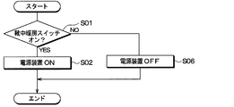
図7は、本実施形態のフロアマット12を図1のII方向から見た矢視図であって、第1実施形態の図2に相当する図である。この図7に示すように、本実施形態では、フロアマット12は、マット本体121と誘導加熱コイル122とを有しているが、履物検知スイッチ123を有していない。本実施形態は、この点において第1実施形態と異なっている。
本実施形態では履物検知スイッチ123が設けられていないので、制御部14が実行する制御処理を示すフローチャートは、図8のようになる。この図8に示すように、第1実施形態の図6に含まれるステップS03~S05は、図8のフローチャートには無い。また、図8のステップS01、S02、およびS06はそれぞれ図6のものと同じである。図8のフローチャートにおいて、ステップS02またはステップS06の次はステップS01へ進む。
従って、靴中暖房スイッチ18がオン状態である場合には、靴72がフロアマット12において、マーカ124が示す加熱可能位置に置かれると、靴72の加熱部材724が誘導加熱コイル122によって加熱され、靴中暖房が行われる。
本実施形態では、前述の第1実施形態と共通の構成から奏される効果を第1実施形態と同様に得ることができる。
(第3実施形態)
次に、第3実施形態について説明する。本実施形態では、前述の第1実施形態と異なる点を主として説明する。
次に、第3実施形態について説明する。本実施形態では、前述の第1実施形態と異なる点を主として説明する。
図9は、本実施形態のフロアマット12を図1のII方向から見た矢視図であって、第1実施形態の図2に相当する図である。この図9に示すように、本実施形態では、図2のマーカ124が設けられていない。本実施形態は、この点において第1実施形態と異なっている。
また、本実施形態では第1実施形態とは異なり、誘導加熱コイル122と履物検知スイッチ123とが1つずつ設けられている。本実施形態の誘導加熱コイル122は1つであるが、フロアマット12上に置かれた左右の靴72をそれぞれ同時に加熱することができるようになっている。そのために、誘導加熱コイル122は、車両幅方向DR3において左右の靴72が置かれる幅の全体にわたって拡がっている。
また、履物検知スイッチ123は、左右の靴72の一方が置かれる位置に設けられていればよい。本実施形態では、履物検知スイッチ123は、右足用の靴72が置かれる位置に設けられている。
本実施形態において制御部14が実行する制御処理は第1実施形態と同様であるので、図6のフローチャートのとおりである。
本実施形態では、前述の第1実施形態と共通の構成から奏される効果を第1実施形態と同様に得ることができる。
(第4実施形態)
次に、第4実施形態について説明する。本実施形態では、前述の第2実施形態と異なる点を主として説明する。
次に、第4実施形態について説明する。本実施形態では、前述の第2実施形態と異なる点を主として説明する。
図10は、本実施形態の加熱装置10の電気的構成を示したブロック構成図であって、第1実施形態の図5に相当する図である。図10に示すように、本実施形態では、第2実施形態と同様に履物検知スイッチ123は設けられていない。しかし、本実施形態の加熱装置10の制御部14には、第2実施形態とは異なり、車両69が有するシートベルト着用検知スイッチ20からの信号が入力されるようになっている。
本実施形態の加熱装置10が搭載される車両69は、乗員が着座する複数の座席を有している。その複数の座席には例えば図1の運転席78も含まれる。その複数の座席にはそれぞれ、シートベルトと、シートベルト着用検知スイッチ20とが設けられている。すなわち、シートベルト着用検知スイッチ20は、複数の座席の数だけ設けられている。
また、フロアマット12は第2実施形態と同様であるので、図7に示されている。このフロアマット12は、車室内において上記複数の座席それぞれの足元部分に配置されている。要するに、その複数の座席のうちの一の座席を所定座席とすれば、フロアマット12は、その所定座席に対応する箇所に設けられている。
シートベルト着用検知スイッチ20は、複数の座席のうちそのシートベルト着用検知スイッチ20が設けられた所定座席にて乗員70がシートベルトを着用したことを検知するスイッチである。従って、シートベルト着用検知スイッチ20は、その所定座席に乗員70が居ることを検知する乗員検知部として機能する。
図11は、本実施形態の制御部14が実行する制御処理を示すフローチャートであって、第1実施形態の図6に相当する図である。この図11の制御処理は図6の制御処理と同様に実行される。すなわち、制御部14は、例えば車両69のイグニッションスイッチがオフからオンにされると図11の制御処理を開始し、その図11の制御処理を周期的に繰り返し実行する。
また、シートベルト着用検知スイッチ20およびフロアマット12は複数の座席にそれぞれ設けられているので、図11の制御処理は、その座席毎に独立して並列実行される。以下の図11の説明では、複数の座席のうちの一の座席である所定座席において靴中暖房を実行することを述べる。
図11のステップS01、S02、S04、S05、およびS06はそれぞれ図6のものと同じであるので、それらのステップの説明を省略する。図11の制御処理では、図6のステップS03がステップS031に置き換わっている。
その図11のフローチャートにおいてステップS02の次はステップS031へ進む。そのステップS031では、制御部14は、乗員70が所定座席に居ることがシートベルト着用検知スイッチ20によって検知されたか否かを判定する。具体的に制御部14は、その所定座席にてシートベルトの着用がシートベルト着用検知スイッチ20によって検知された場合には、乗員70が所定座席に居ると判定する。その一方で、制御部14は、シートベルトの着用がシートベルト着用検知スイッチ20によって検知されていない場合には、乗員70が所定座席に居ないと判定する。
ステップS031において、乗員70が所定座席に居ると判定した場合には、ステップS04へ進む。すなわち、制御部14は、乗員70が所定座席に居ることがシートベルト着用検知スイッチ20によって検知された場合には、ステップS04において第1実施形態と同様に誘導加熱コイル122に通電する。
逆に、ステップS031において、乗員70が所定座席に居ないと判定した場合には、ステップS05へ進む。すなわち、制御部14は、乗員70が所定座席に居ないことがシートベルト着用検知スイッチ20によって検知された場合には、ステップS05において第1実施形態と同様に誘導加熱コイル122への通電を停止する。
本実施形態では、前述の第2実施形態と共通の構成から奏される効果を第2実施形態と同様に得ることができる。
また、本実施形態によれば、複数の座席のうちの一の座席を所定座席とすれば、車両69は、その所定座席に乗員が居ることを検知する乗員検知部としてのシートベルト着用検知スイッチ20を有している。また、フロアマット12は、車室内においてその所定座席の位置に対応する箇所に設けられている。そして、制御部14は、乗員70が所定座席に居ることがシートベルト着用検知スイッチ20によって検知された場合に、誘導加熱コイル122に通電する。
従って、乗員70がその所定座席に居ることに応じて誘導加熱コイル122の通電が実行され、加熱装置10の不必要な電力消費を回避することができる。そして、靴中暖房スイッチ18がオン状態であり且つ乗員70が所定座席でシートベルトを着用している場合には、その乗員70が靴72をフロアマット12のマーカ124が示す加熱可能位置に置けば、誘導加熱による靴中暖房が行われる。
(第5実施形態)
次に、第5実施形態について説明する。本実施形態では、前述の第1実施形態と異なる点を主として説明する。
次に、第5実施形態について説明する。本実施形態では、前述の第1実施形態と異なる点を主として説明する。
図12は、本実施形態の加熱装置10の電気的構成を示したブロック構成図であって、第1実施形態の図5に相当する図である。図12に示すように、本実施形態の加熱装置10は表示装置22を備えている。そして、その表示装置22は、制御部14へ電気的に接続されている。本実施形態はこれらの点において第1実施形態と異なっている。
図12に示す表示装置22は、誘導加熱コイル122が通電されていることを表示する。別言すれば、表示装置22は、誘導加熱コイル122が通電されていることを視覚的に乗員70へ知らせる報知装置である。例えば、表示装置22は、発光ダイオード等で構成されたインジケータであり、乗員70が視認しやすいように例えば車室内のインストルメントパネルの一部に設けられている。そして、表示装置22は、制御部14からの制御信号に従って、誘導加熱コイル122の通電中には点灯し、誘導加熱コイル122の非通電中には消灯する。
例えば、表示装置22は、誘導加熱コイル122が複数設けられている場合には誘導加熱コイル122毎に通電中と非通電中とを表示してもよい。或いは、表示装置22は、複数の誘導加熱コイル122の何れかが通電中である場合に通電中の表示を行い、誘導加熱コイル122の全部が非通電中である場合に非通電中の表示を行ってもよい。
なお、表示装置22は、例えば電源装置16から電力供給されている。そのため、例えば後述の図13のステップS06で電源装置16が停止状態にされた場合には、表示装置22は消灯する。
図13は、本実施形態の制御部14が実行する制御処理を示すフローチャートであって、第1実施形態の図6に相当する図である。この図13の制御処理は図6の制御処理と同様に実行される。すなわち、制御部14は、例えば車両69のイグニッションスイッチがオフからオンにされると図13の制御処理を開始し、その図13の制御処理を周期的に繰り返し実行する。
図13のステップS01~S06はそれぞれ図6のものと同じであるので、それらのステップの説明を省略する。図13の制御処理では、ステップS03とステップS04との間にステップS07が設けられ、ステップS03とステップS05との間にステップS08が設けられている。図13の制御処理は、このステップS07、S08が設けられている点で図6の制御処理と異なっている。
図13に示すように、ステップS03において、履物検知スイッチ123がオン状態であると制御部14が判定した場合には、ステップS07へ進む。その一方で、履物検知スイッチ123がオフ状態であると制御部14が判定した場合には、ステップS08へ進む。
ステップS07において、制御部14は、誘導加熱コイル122が通電中であること示す表示、すなわち、通電中の表示(言い換えれば、送電中の表示)を表示装置22に行わせる。その通電中の表示が既に行われている場合にはそれが継続される。その通電中の表示とは、例えば表示装置22が点灯することである。ステップS07の次はステップS04へ進む。
ステップS08において、制御部14は、誘導加熱コイル122が非通電中であること示す表示、すなわち、非通電中の表示(言い換えれば、非送電中の表示)を表示装置22に行わせる。その非通電中の表示が既に行われている場合にはそれが継続される。その非通電中の表示とは、例えば表示装置22が消灯することである。ステップS08の次はステップS05へ進む。
本実施形態では、前述の第1実施形態と共通の構成から奏される効果を第1実施形態と同様に得ることができる。
また、本実施形態によれば、加熱装置10は、フロアマット12の誘導加熱コイル122が通電されていることを表示する表示装置22を備えている。従って、乗員70の靴72が加熱されていることを、その乗員70の視覚に訴えて乗員70に認識させることが可能である。
なお、本実施形態は第1実施形態に基づいた変形例であるが、本実施形態を前述の第2~第4実施形態のそれぞれと組み合わせることも可能である。
(第6実施形態)
次に、第6実施形態について説明する。本実施形態では、前述の第5実施形態と異なる点を主として説明する。
次に、第6実施形態について説明する。本実施形態では、前述の第5実施形態と異なる点を主として説明する。
本実施形態では、表示装置22の配置場所が第5実施形態と異なっている。これを除き、本実施形態は第5実施形態と同様である。
具体的には、表示装置22は、図2に示すフロアマット12のうちマーカ124が設けられた場所に配置されている。例えば、表示装置22は、マーカ124の外縁に沿って連なる複数の発光インジケータで構成されている。これにより、表示装置22が点灯すると、マーカ124が発光したように見える。すなわち、フロアマット12に設けられたマーカ124が表示装置22としての機能を備えているように乗員70に見せることが可能である。
本実施形態では、前述の第5実施形態と共通の構成から奏される効果を第5実施形態と同様に得ることができる。
(第7実施形態)
次に、第7実施形態について説明する。本実施形態では、前述の第1実施形態と異なる点を主として説明する。
次に、第7実施形態について説明する。本実施形態では、前述の第1実施形態と異なる点を主として説明する。
図14は、本実施形態の加熱装置10の電気的構成を示したブロック構成図であって、第1実施形態の図5に相当する図である。図14に示すように、本実施形態の加熱装置10は、音発生装置であるスピーカ26を備えている。そして、そのスピーカ26は、制御部14へ電気的に接続されている。これらの点において本実施形態は第1実施形態と異なっており、他の点については第1実施形態と同様である。
図14に示すスピーカ26は、誘導加熱コイル122が通電されていることを聴覚的に乗員70へ知らせる報知装置である。例えば、スピーカ26は、乗員70がスピーカ26からの音を聞きやすいように、例えば車室内のインストルメントパネルの一部に設けられている。そして、スピーカ26は、制御部14からの制御信号に従って音を発する。
なお、スピーカ26は、例えば電源装置16から電力供給されている。そのため、例えば後述の図15のステップS06で電源装置16が停止状態にされた場合には、スピーカ26は音を発しなくなる。
図15は、本実施形態の制御部14が実行する制御処理を示すフローチャートであって、第1実施形態の図6に相当する図である。この図15の制御処理は図6の制御処理と同様に実行される。すなわち、制御部14は、例えば車両69のイグニッションスイッチがオフからオンにされると図15の制御処理を開始し、その図15の制御処理を周期的に繰り返し実行する。
図15のステップS01~S06はそれぞれ図6のものと同じであるので、それらのステップの説明を省略する。図15の制御処理では、ステップS03とステップS04との間にステップS09が設けられ、ステップS03とステップS05との間にステップS10が設けられている。図15の制御処理は、このステップS09、S10が設けられている点で図6の制御処理と異なっている。
図15に示すように、ステップS03において、履物検知スイッチ123がオン状態であると制御部14が判定した場合には、ステップS09へ進む。その一方で、履物検知スイッチ123がオフ状態であると制御部14が判定した場合には、ステップS10へ進む。
ステップS09において、制御部14は、誘導加熱コイル122が通電中であることをスピーカ26からの音で乗員70へ報知する。具体的には、制御部14は、誘導加熱コイル122が通電中であることを表す予め定められた音すなわち通電報知音を、スピーカ26から発生させる。例えば、その通電報知音は、誘導加熱コイル122の通電中に継続して発生させられてもよいし、誘導加熱コイル122が非通電中から通電中に切り替わった際に発生させられるだけであってもよい。ステップS09の次はステップS04へ進む。
ステップS10において、制御部14は、誘導加熱コイル122が非通電中であることをスピーカ26からの音で乗員70へ報知する。具体的には、制御部14は、誘導加熱コイル122が非通電中であることを表す予め定められた音すなわち非通電報知音を、スピーカ26から発生させる。その非通電報知音は、通電報知音に対し、例えばメロディまたは音色が異なることにより、異なる音になっている。
例えば、その非通電報知音は、誘導加熱コイル122の非通電中に継続して発生させられてもよいし、誘導加熱コイル122が通電中から非通電中に切り替わった際に発生させられるだけであってもよい。ステップS10の次はステップS05へ進む。
本実施形態では、前述の第1実施形態と共通の構成から奏される効果を第1実施形態と同様に得ることができる。
また、本実施形態によれば、加熱装置10は、誘導加熱コイル122が通電されていることを聴覚的に乗員70へ知らせるスピーカ26を備えている。従って、乗員70の靴72が加熱されていることを、その乗員70の聴覚に訴えて乗員70に認識させることが可能である。例えば車両運転中の乗員70は視線変化を伴わずに、誘導加熱コイル122が通電されていることを知ることができる。
なお、本実施形態は第1実施形態に基づいた変形例であるが、本実施形態を前述の第2~第6実施形態のそれぞれと組み合わせることも可能である。例えば、本実施形態のスピーカ26は、第5、第6実施形態の表示装置22と共に用いられてもよい。
(第8実施形態)
次に、第8実施形態について説明する。本実施形態では、前述の第1実施形態と異なる点を主として説明する。
次に、第8実施形態について説明する。本実施形態では、前述の第1実施形態と異なる点を主として説明する。
本実施形態では、誘導加熱コイル122の通電中に、加熱部材724に対する誘導加熱コイル122の加熱量Wcが切り替えられる。この点において本実施形態は第1実施形態と異なっており、他の点については第1実施形態と同様である。
具体的には、履物検知スイッチ123がオン状態であると図6のステップS03で判定された場合には、図16の制御処理が開始される。そして、制御部14は、図16の制御処理を図6の制御処理と並列に実行し、履物検知スイッチ123がオン状態であるという判定を継続している間は、その図16の制御処理を継続する。その一方で、制御部14は、靴中暖房スイッチ18がオフ状態であると図6のステップS01で判定した場合または履物検知スイッチ123がオフ状態であるとステップS03で判定した場合には、図16の制御処理を止める。
なお、図6のステップS03において、履物検知スイッチ123がオン状態であると判定されているときに、履物検知スイッチ123がオン状態から瞬間的にオフ状態へ切り替えられても、オン状態であるというステップS03の判定は継続される。その瞬間的なオフ状態への切替えは、後述の検知器操作に含まれた操作だからである。
図16の制御処理が開始されると、先ず、ステップS001において、制御部14は、検知器である履物検知スイッチ123がオン状態であるときに所定の検知器操作が履物検知スイッチ123に対して為されたか否かを判定する。その検知器操作とは、例えば、履物検知スイッチ123がオン状態から瞬間的にオフ状態に切り替えられ再びオン状態に戻される瞬間的オフ操作である。そのオフ状態が瞬間的であるか否かは、履物検知スイッチ123がオン状態からオフ状態に切り替えられた時点から再びオン状態に戻される時点までの時間間隔が所定の判定時間以下であるか否かによって判定される。
ステップS001において、履物検知スイッチ123がオン状態であるときに検知器操作が履物検知スイッチ123に対して為されたと判定された場合には、ステップS002へ進む。その一方で、検知器操作が履物検知スイッチ123に対して為されていないと判定された場合には、ステップS001の判定が再び行われる。
ステップS002において、制御部14は、加熱部材724に対する誘導加熱コイル122の加熱量Wcを、検知器操作が為される前に対して変化させる。その加熱量Wcの単位は例えば「W」であり、加熱量Wcは誘導加熱コイル122へ通電される電流の大きさに応じて増減される。
具体的に、制御部14は、検知器操作が為されたとステップS001で判定する毎に、要するに、検知器操作が為される毎に、誘導加熱コイル122の加熱量Wcを段階的に切り替える。
例えば、図17に示すように、「弱<中<強」という加熱量Wcの大きさの順序で、弱、中、強の加熱量Wcが予め定められている。また、図17のヒータオフとは、加熱量Wcが零であること、すなわち、誘導加熱コイル122への通電を止めることである。
また、加熱量Wcの初期値は、本実施形態では、弱の加熱量Wcとされている。従って、例えば、図6のステップS03の判定が、履物検知スイッチ123がオフ状態であるという判定から、オン状態であるという判定へ切り替わった場合には、ステップS04で、誘導加熱コイル122の加熱量Wcは、先ず、弱の加熱量Wcになる。
そして、図17に示すように、検知器操作が為される毎に、制御部14は、誘導加熱コイル122の加熱量Wcを、弱、中、強、ヒータオフの順に切り替える。更に、図17の加熱量Wcの切替わりがヒータオフのときに検知器操作が為されると、制御部14は、誘導加熱コイル122の加熱量Wcを弱の加熱量Wcに戻す。
なお、誘導加熱コイル122と履物検知スイッチ123は、図2に示すようにそれぞれ複数設けられている。本実施形態では、複数の履物検知スイッチ123のうちの何れかに対して検知器操作が為されれば、制御部14は、フロアマット12に設けられた全部の誘導加熱コイル122の加熱量Wcを切り替える。
本実施形態では、前述の第1実施形態と共通の構成から奏される効果を第1実施形態と同様に得ることができる。
また、本実施形態によれば、図16および図17に示すように、履物検知スイッチ123がオン状態であるときに所定の検知器操作が履物検知スイッチ123に対して為された場合には、制御部14は、加熱部材724に対する誘導加熱コイル122の加熱量Wcを、検知器操作が為される前に対して変化させる。従って、乗員70は足701の動作によって加熱量Wcの調整を行うことが可能である。
また、本実施形態によれば、図16のステップS001で判定される検知器操作とは、例えば、履物検知スイッチ123がオン状態から瞬間的にオフ状態に切り替えられ再びオン状態に戻される瞬間的オフ操作である。従って、乗員70は単純な足701の動作によって加熱量Wcの調整を行うことが可能である。
なお、本実施形態は第1実施形態に基づいた変形例であるが、本実施形態を前述の第3、第5~7実施形態のそれぞれと組み合わせることも可能である。
(他の実施形態)
(1)上述の各実施形態において、フロアマット12のマット本体121はゴム製であるが、布など他の絶縁材料で構成されていても差し支えない。
(1)上述の各実施形態において、フロアマット12のマット本体121はゴム製であるが、布など他の絶縁材料で構成されていても差し支えない。
(2)上述の各実施形態において、加熱部材724は乗員70の足701に接触するが、誘導加熱された加熱部材724の熱が乗員70の足701へ伝われば、加熱部材724は乗員70の足701に接触する必要はない。
(3)上述の第1実施形態において、フロアマット12のマーカ124は、例えば図2に示すように、靴72の靴底721の形状に合った図形で構成されているが、そのマーカ124の形状に限定はない。このことは、第2、第4~8実施形態についても同様である。
例えば、フロアマット12のマーカ124は、図18に示すように枠形状を成していてもよいし、図19に示すように矩形形状を成していてもよい。
更に言えば、図2および図19に示す靴載せ領域124a内の色がその靴載せ領域124aの周囲の色に対し異なる色で構成されており、それにより、目印としてのマーカ124が形成されていてもよい。
また、フロアマット12の表面121aが起毛された表面となっている場合には、図2および図19に示す靴載せ領域124a内に植毛された毛の長さがその靴載せ領域124aの周囲に植毛された毛に対し異なる長さとなっていてもよい。このようにすれば、毛の長さの差異によって、目印としてのマーカ124が形成される。例えば、靴載せ領域124a内の毛の長さが靴載せ領域124aの周囲の毛に対し短くなっていてもよい。或いは、靴載せ領域124aの周囲には植毛されている一方で、靴載せ領域124a内には植毛されておらず、その靴載せ領域124aが泥除け部等として機能してもよい。
(4)上述の第1、第3、第5~8実施形態において、履物検知スイッチ123をオン状態にするための所定の荷重閾値は、例えば靴72の自重で履物検知スイッチ123がオン状態になるように予め実験的に設定されている。しかしながら、これは一例であり、その所定の荷重閾値は、靴72だけの自重では履物検知スイッチ123がオン状態にはならず靴72および乗員70の足701の自重で履物検知スイッチ123がオン状態になるように設定されていることも考え得る。
(5)上述の第1、第3、第5~8実施形態において、履物検知スイッチ123は押しボタンスイッチであるが、他の形式のスイッチまたはセンサ等であっても差し支えない。
(6)上述の各実施形態において、電源装置16の作動状態と停止状態とを切り替えるための靴中暖房スイッチ18が設けられているが、その靴中暖房スイッチ18は無くても差し支えない。その靴中暖房スイッチ18が無い場合には、例えば電源装置16は、車両69のイグニッションスイッチがオンにされると作動状態になる。
(7)上述の第4実施形態において、シートベルト着用検知スイッチ20は、そのシートベルト着用検知スイッチ20が設けられた所定座席に乗員70が居ることを検知する乗員検知部として機能するが、これは一例である。例えば、その乗員検知部は、シートベルト着用検知スイッチ20ではなく、着座した乗員の体重に反応する着座センサまたは車室内を観察するカメラなどであってもよい。
(8)上述の第5実施形態において、表示装置22は、例えば発光ダイオード等で構成されたインジケータであるが、液晶ディスプレイ等で構成されていてもよい。また、表示装置22は、車室内空調機器などが有する他の表示部と一体に設けられていても差し支えない。また、表示装置22は、インストルメントパネルに設けられていなくてもよい。
(9)上述の第5、第6実施形態において、表示装置22は、誘導加熱コイル122の非通電中には消灯するが、これは一例である。例えば、表示装置22は誘導加熱コイル122の非通電中にも点灯し、その誘導加熱コイル122の非通電中における表示装置22の点灯の仕方(例えば、発光色または明るさ)が、誘導加熱コイル122の通電中と比較して異なっていてもよい。
(10)上述の第6実施形態において、表示装置22はマーカ124とは別の物であるが、これらは別個の物として構成されていなくてもよい。例えば、表示装置22とマーカ124とが、その表示装置22の機能とマーカ124の機能とを併せ持つ1つの物として構成されていても差し支えない。
(11)上述の第7実施形態において、図15のステップS10では、制御部14は、非通電報知音をスピーカ26から発生させるが、これは一例である。例えば、通電報知音が誘導加熱コイル122の通電中に継続的または断続的に発生させられるのであれば、図15のステップS10において、制御部14は、その通電報知音を止めてスピーカ26から音を発生させないようにしてもよい。
(12)上述の第8実施形態において、図16のステップS001で判定される所定の検知器操作は、例えば履物検知スイッチ123がオン状態から瞬間的にオフ状態に切り替えられ再びオン状態に戻される瞬間的オフ操作であるが、これは一例である。例えば、その検知器操作は瞬間的オフ操作でなくてもよいし、或いは、その瞬間的オフ操作が複数回連続する操作であってもよい。
(13)上述の第8実施形態において、図17に示すように、誘導加熱コイル122の加熱量Wcは段階的に切り替えられ、誘導加熱コイル122はヒータオフにもなるが、これは一例である。図17の加熱量Wcの切替えにおいて、例えばヒータオフは無くてもよいし、加熱量Wcは、弱、中、強の3段切替えでなくもよい。
(14)上述の第8実施形態において、図16のステップS001で判定される所定の検知器操作は図2の履物検知スイッチ123に対する操作であるが、これは一例である。例えば、履物検知スイッチ123上に靴72が載れば履物検知スイッチ123と同時にオン状態になる別の押しボタンスイッチが履物検知スイッチ123に近接してフロアマット12に設けられていることが想定される。その場合には、その別の押しボタンスイッチと履物検知スイッチ123とが、フロアマット12に設けられた検知器を構成し、所定の検知器操作は、その別の押しボタンスイッチに対する操作であってもよい。
(15)上述の第8実施形態では、図16の制御処理において、複数の履物検知スイッチ123のうちの何れかに対して検知器操作が為されれば、制御部14は、フロアマット12に設けられた全部の誘導加熱コイル122の加熱量Wcを切り替えるが、これは一例である。例えば、複数の履物検知スイッチ123のうち、或る履物検知スイッチ123に対して検知器操作が為された場合には、制御部14は、上記或る履物検知スイッチ123に対応して設けられた誘導加熱コイル122の加熱量Wcだけを切り替えてもよい。
(16)上述の第1実施形態において、誘導加熱コイル122、履物検知スイッチ123、およびマーカ124はフロアマット12に設けられているが、フロアマット12に限らず、他の部位に設けられていても差し支えない。すなわち、誘導加熱コイル122と履物検知スイッチ123とマーカ124とを有する履物載置部は、フロアマット12に限らず、乗員70に踏込み操作される図1のペダル781、または、乗員70の靴72が載せられる図2のフットレスト782であってもよい。このようにすることにより、車両69の中で実用的な箇所に誘導加熱コイル122を設けることが可能である。なお、このことは第2~5実施形態についても同様である。
また、上記履物載置部としてのペダル781は、図1ではアクセルペダルであるが、ブレーキペダルまたはクラッチペダル等であってもよい。また、フットレスト782とは、具体的に言えば、運転席78の足元部分に配置され車両底部74に固定された足載せ台である。
(17)上述の各実施形態において、靴72の加熱部材724は金属箔で構成されているが、例えば導電金属製の線材など金属箔以外の材料で構成されていても差し支えない。
(18)上述の各実施形態において、誘導加熱される加熱部材724は靴72に設けられているが、例えば草履または靴下など他の履物に設けられていても差し支えない。
(19)上述の各実施形態において、誘導加熱コイル122は、車両69の座席の位置に対応させて設けられているが、必ずしも車両69の座席の位置に対応させて設けられている必要はない。
(20)上述の各実施形態において、図6、図8、図11、図13、図15、および図16のフローチャートに示す各ステップの処理はコンピュータプログラムによって実現されるものであるが、ハードロジックで構成されるものであっても差し支えない。
なお、本開示は上記した実施形態に限定されるものではない。本開示は、様々な変形例や均等範囲内の変形をも包含する。また、上記各実施形態は、互いに無関係なものではなく、組み合わせが明らかに不可な場合を除き、適宜組み合わせが可能である。また、上記各実施形態において、実施形態を構成する要素は、特に必須であると明示した場合および原理的に明らかに必須であると考えられる場合等を除き、必ずしも必須のものではないことは言うまでもない。
また、上記各実施形態において、実施形態の構成要素の個数、数値、量、範囲等の数値が言及されている場合、特に必須であると明示した場合および原理的に明らかに特定の数に限定される場合等を除き、その特定の数に限定されるものではない。また、上記各実施形態において、構成要素等の材質、形状、位置関係等に言及するときは、特に明示した場合および原理的に特定の材質、形状、位置関係等に限定される場合等を除き、その材質、形状、位置関係等に限定されるものではない。
(まとめ)
上記各実施形態の一部または全部で示された第1の観点によれば、履物載置部に設けられた目印は、その履物載置部において、誘導加熱コイルが加熱部材を加熱することができる履物の位置を表示する。
上記各実施形態の一部または全部で示された第1の観点によれば、履物載置部に設けられた目印は、その履物載置部において、誘導加熱コイルが加熱部材を加熱することができる履物の位置を表示する。
また、第2の観点によれば、目印は、載置部表面のうちの一部の領域を示す。そして、誘導加熱コイルの少なくとも一部は、載置部表面の面方向でその一部の領域が占める範囲内に入っている。従って、加熱装置が電磁誘導により加熱することが可能な履物の位置を、乗員にとって明瞭に且つ判りやすく示すことができる。
また、第3の観点によれば、履物載置部に設けられた検知器は、その検知器上に履物が載ることでオン状態になる。そして、誘導加熱コイルは、その検知器がオン状態になった場合に通電される。
また、第4の観点によれば、履物載置部に設けられた検知器は、その検知器上に履物が載ることでオン状態になる。そして、誘導加熱コイルは、その検知器がオン状態になった場合に通電される。これにより、乗員は、履物の加熱を欲する場合に履物で検知器を踏むなどして容易に検知器をオン状態にすることができる。従って、履物の加熱の必要性に応じて誘導加熱コイルの通電がオンオフされ、加熱装置の不必要な電力消費を回避することができる。
また、第5の観点によれば、上述の第4の観点で説明したことに加え更に、検知器は、載置部表面の面方向で上記一部の領域が占める範囲内に配置される。従って、その一部の領域上に重ねて履物が置かれれば、それに伴い履物が検知器上に載ることになる。
また、第6の観点によれば、制御部は、検知器がオン状態であるときに所定の検知器操作が検知器に対して為された場合には、加熱部材に対する誘導加熱コイルの加熱量を、検知器操作が為される前に対して変化させる。従って、乗員は足の動作によって加熱量の調整を行うことが可能である。
また、第7の観点によれば、検知器操作は、検知器がオン状態から瞬間的にオフ状態に切り替えられ再びオン状態に戻される瞬間的オフ操作、またはその瞬間的オフ操作が連続する操作である。従って、乗員は単純な足の動作によって加熱量の調整を行うことが可能である。
また、第8の観点によれば、車両は、乗員が着座する所定座席と、その所定座席に乗員が居ることを検知する乗員検知部とを有している。履物載置部は、車室内においてその所定座席の位置に対応する箇所に設けられている。そして、制御部は、乗員が所定座席に居ることが乗員検知部によって検知された場合に、誘導加熱コイルに通電する。従って、乗員がその所定座席に居ることに応じて誘導加熱コイルの通電がオンオフされ、加熱装置の不必要な電力消費を回避することができる。
また、第9の観点によれば、表示装置は、誘導加熱コイルが通電されていることを視覚的に乗員へ知らせる。そして、その表示装置は、履物載置部のうち目印が設けられた場所に配置されている。従って、履物載置部に設けられた目印が表示装置としての機能を備えているように乗員に見せることが可能である。
また、第10の観点によれば、加熱装置は、誘導加熱コイルが通電されていることを表示する表示装置を備えている。従って、乗員の靴が加熱されていることを、その乗員の視覚に訴えて乗員に認識させることが可能である。
また、第11の観点によれば、履物載置部は、車室の床面上に設置されるフロアマット、乗員に踏込み操作されるペダル、または、車室の床に固定され履物が載せられるフットレストである。従って、車両の中で実用的な箇所に誘導加熱コイルを設けることが可能である。
また、第12の観点によれば、音発生装置は、誘導加熱コイルが通電されていることを聴覚的に乗員へ知らせる。従って、乗員の履物が加熱されていることを、その乗員の聴覚に訴えて乗員に認識させることが可能である。
Claims (12)
- 車両(69)に搭載される加熱装置であって、
車室内で乗員(70)の履物(72)が載せられる履物載置部(12、781、782)に設けられ、前記履物が有する加熱部材(724)を、通電されることで電磁誘導により加熱する誘導加熱コイル(122)と、
前記履物載置部に設けられた目印(124)とを備え、
該目印は、前記履物載置部において、前記誘導加熱コイルが前記加熱部材を加熱することができる前記履物の位置を表示する加熱装置。 - 前記履物載置部は、前記履物が載せられる載置部表面(121a)を有し、
前記目印は、前記載置部表面のうちの一部の領域(124a)を示し、
前記誘導加熱コイルの少なくとも一部は、前記載置部表面の面方向で前記一部の領域が占める範囲内に入っている請求項1に記載の加熱装置。 - 車両(69)に搭載される加熱装置であって、
車室内で乗員(70)の履物(72)が載せられる履物載置部(12、781、782)に設けられ、前記履物が有する加熱部材(724)を、通電されることで電磁誘導により加熱する誘導加熱コイル(122)と、
前記履物載置部に設けられた検知器(123)とを備え、
該検知器は、該検知器上に前記履物が載ることでオン状態になり、
前記誘導加熱コイルは、前記検知器が前記オン状態になった場合に通電される加熱装置。 - 前記履物載置部に設けられた検知器(123)を備え、
該検知器は、該検知器上に前記履物が載ることでオン状態になり、
前記誘導加熱コイルは、前記検知器が前記オン状態になった場合に通電される請求項1または2に記載の加熱装置。 - 前記履物載置部に設けられた検知器(123)を備え、
該検知器は、前記面方向で前記一部の領域が占める範囲内に配置され、前記検知器上に前記履物が載ることでオン状態になり、
前記誘導加熱コイルは、前記検知器が前記オン状態になった場合に通電される請求項2に記載の加熱装置。 - 前記検知器が前記オン状態であるときに所定の検知器操作が前記検知器に対して為された場合には、前記加熱部材に対する前記誘導加熱コイルの加熱量(Wc)を、前記検知器操作が為される前に対して変化させる制御部(14)を備えている請求項3ないし5のいずれか1つに記載の加熱装置。
- 前記検知器は、該検知器上に載っていた前記履物が載らなくなることで前記オン状態からオフ状態になり、
前記検知器操作は、前記検知器が前記オン状態から瞬間的に前記オフ状態に切り替えられ再び前記オン状態に戻される瞬間的オフ操作、または該瞬間的オフ操作が連続する操作である請求項6に記載の加熱装置。 - 制御部(14)を備え、
前記車両は、前記乗員が着座する所定座席と、該所定座席に前記乗員が居ることを検知する乗員検知部(20)とを有し、
前記履物載置部は、前記車室内において前記所定座席の位置に対応する箇所に設けられ、
前記制御部は、前記乗員が前記所定座席に居ることが前記乗員検知部によって検知された場合に、前記誘導加熱コイルに通電する請求項1または2に記載の加熱装置。 - 前記誘導加熱コイルが通電されていることを視覚的に前記乗員へ知らせる表示装置(22)を備え、
前記表示装置は、前記履物載置部のうち前記目印が設けられた場所に配置されている請求項1、2、4、5、8のいずれか1つに記載の加熱装置。 - 前記誘導加熱コイルが通電されていることを表示する表示装置(22)を備えている請求項1ないし8のいずれか1つに記載の加熱装置。
- 前記履物載置部は、前記車室の床面(74a)上に設置されるフロアマット(12)、前記乗員に踏込み操作されるペダル(781)、または、前記車室の床(74)に固定され前記履物が載せられるフットレスト(782)である請求項1ないし10のいずれか1つに記載の加熱装置。
- 前記誘導加熱コイルが通電されていることを聴覚的に前記乗員へ知らせる音発生装置(26)を備えている請求項1ないし11のいずれか1つに記載の加熱装置。
Applications Claiming Priority (2)
| Application Number | Priority Date | Filing Date | Title |
|---|---|---|---|
| JP2016061962A JP2019091521A (ja) | 2016-03-25 | 2016-03-25 | 加熱装置 |
| JP2016-061962 | 2016-03-25 |
Publications (1)
| Publication Number | Publication Date |
|---|---|
| WO2017163749A1 true WO2017163749A1 (ja) | 2017-09-28 |
Family
ID=59899946
Family Applications (1)
| Application Number | Title | Priority Date | Filing Date |
|---|---|---|---|
| PCT/JP2017/006899 Ceased WO2017163749A1 (ja) | 2016-03-25 | 2017-02-23 | 加熱装置 |
Country Status (2)
| Country | Link |
|---|---|
| JP (1) | JP2019091521A (ja) |
| WO (1) | WO2017163749A1 (ja) |
Families Citing this family (1)
| Publication number | Priority date | Publication date | Assignee | Title |
|---|---|---|---|---|
| KR102701835B1 (ko) * | 2024-03-13 | 2024-09-03 | 주식회사 온프 | 폐플라스틱 리사이클링 기반 극세사 소재를 활용한 저주파 유도 가열 기술 적용 안전화 및 이의 제조 방법 |
Citations (9)
| Publication number | Priority date | Publication date | Assignee | Title |
|---|---|---|---|---|
| JPH0521132A (ja) * | 1991-07-08 | 1993-01-29 | Natl House Ind Co Ltd | 足温器 |
| JPH05290697A (ja) * | 1992-04-15 | 1993-11-05 | Matsushita Electric Works Ltd | 人体検知装置 |
| JPH07236502A (ja) * | 1994-02-28 | 1995-09-12 | Takumi Ando | 保温機能付スキー用具及びその加熱装置 |
| JP2002317953A (ja) * | 2001-04-17 | 2002-10-31 | Mitsuo Honma | 感知式ホットカーペット並びにホットカーペット用センサー機構部。 |
| US20080197126A1 (en) * | 2007-02-16 | 2008-08-21 | Thermal Solutions, Inc. | Inductively heated clothing |
| JP2010196972A (ja) * | 2009-02-25 | 2010-09-09 | Brother Ind Ltd | 暖房器具 |
| JP2012157651A (ja) * | 2011-02-02 | 2012-08-23 | Toyota Boshoku Corp | 座席ヒータ |
| US20140137695A1 (en) * | 2012-11-20 | 2014-05-22 | Steven L. Permut | Electrical Heating System Using Designated Areas Like Footrests, Accelerator Pedals and Floor Areas for Directed Heat |
| JP2014205432A (ja) * | 2013-04-12 | 2014-10-30 | 株式会社デンソー | 輻射ヒータ空調システム |
-
2016
- 2016-03-25 JP JP2016061962A patent/JP2019091521A/ja active Pending
-
2017
- 2017-02-23 WO PCT/JP2017/006899 patent/WO2017163749A1/ja not_active Ceased
Patent Citations (9)
| Publication number | Priority date | Publication date | Assignee | Title |
|---|---|---|---|---|
| JPH0521132A (ja) * | 1991-07-08 | 1993-01-29 | Natl House Ind Co Ltd | 足温器 |
| JPH05290697A (ja) * | 1992-04-15 | 1993-11-05 | Matsushita Electric Works Ltd | 人体検知装置 |
| JPH07236502A (ja) * | 1994-02-28 | 1995-09-12 | Takumi Ando | 保温機能付スキー用具及びその加熱装置 |
| JP2002317953A (ja) * | 2001-04-17 | 2002-10-31 | Mitsuo Honma | 感知式ホットカーペット並びにホットカーペット用センサー機構部。 |
| US20080197126A1 (en) * | 2007-02-16 | 2008-08-21 | Thermal Solutions, Inc. | Inductively heated clothing |
| JP2010196972A (ja) * | 2009-02-25 | 2010-09-09 | Brother Ind Ltd | 暖房器具 |
| JP2012157651A (ja) * | 2011-02-02 | 2012-08-23 | Toyota Boshoku Corp | 座席ヒータ |
| US20140137695A1 (en) * | 2012-11-20 | 2014-05-22 | Steven L. Permut | Electrical Heating System Using Designated Areas Like Footrests, Accelerator Pedals and Floor Areas for Directed Heat |
| JP2014205432A (ja) * | 2013-04-12 | 2014-10-30 | 株式会社デンソー | 輻射ヒータ空調システム |
Also Published As
| Publication number | Publication date |
|---|---|
| JP2019091521A (ja) | 2019-06-13 |
Similar Documents
| Publication | Publication Date | Title |
|---|---|---|
| US10946797B2 (en) | Smart functional leather for steering wheel and dash board | |
| US11665830B2 (en) | Method of making smart functional leather | |
| KR102089519B1 (ko) | 히팅장치에 의한 탑승자 감지 | |
| US11225191B2 (en) | Smart leather with wireless power | |
| KR101526547B1 (ko) | 전기적 기능을 갖는 표면 형성체 | |
| US20090289045A1 (en) | Footwell heating equipment | |
| EP3645341B1 (en) | Smart functional leather for recharging a portable electronic device | |
| WO2014058429A1 (en) | Ventilated and heated vehicle seat assembly | |
| US10946722B2 (en) | Heater device | |
| JP2015223917A (ja) | 車両用暖房装置 | |
| US20210283988A1 (en) | Radiant panel for installation inside a vehicle passenger compartment | |
| KR20030094207A (ko) | 차량 시트 가열 장치 | |
| US9925900B2 (en) | Vehicle seat cushion | |
| JP6840826B2 (ja) | 無線電力式スマート皮革 | |
| US20200323301A1 (en) | Heating device | |
| WO2017022627A1 (ja) | 加熱装置 | |
| CN110546035A (zh) | 用于机动车辆的内部装置部分的扶手 | |
| WO2017163749A1 (ja) | 加熱装置 | |
| CN112805178A (zh) | 座椅加热装置 | |
| US20190064963A1 (en) | Integration of switches in linings | |
| US20220185069A1 (en) | Vehicle zone heating system | |
| JP2020022522A (ja) | 加熱装置および履物加熱システム | |
| JP2023065965A (ja) | ステアリングホイール | |
| JP2018131153A (ja) | 車両用暖房システム |
Legal Events
| Date | Code | Title | Description |
|---|---|---|---|
| NENP | Non-entry into the national phase |
Ref country code: DE |
|
| 121 | Ep: the epo has been informed by wipo that ep was designated in this application |
Ref document number: 17769795 Country of ref document: EP Kind code of ref document: A1 |
|
| 122 | Ep: pct application non-entry in european phase |
Ref document number: 17769795 Country of ref document: EP Kind code of ref document: A1 |
|
| NENP | Non-entry into the national phase |
Ref country code: JP |