WO2017160082A1 - 레이저를 이용한 비접촉식 두께 측정 시스템 및 방법 - Google Patents
레이저를 이용한 비접촉식 두께 측정 시스템 및 방법 Download PDFInfo
- Publication number
- WO2017160082A1 WO2017160082A1 PCT/KR2017/002804 KR2017002804W WO2017160082A1 WO 2017160082 A1 WO2017160082 A1 WO 2017160082A1 KR 2017002804 W KR2017002804 W KR 2017002804W WO 2017160082 A1 WO2017160082 A1 WO 2017160082A1
- Authority
- WO
- WIPO (PCT)
- Prior art keywords
- laser
- acoustic signal
- thickness
- optical acoustic
- signal
- Prior art date
- Legal status (The legal status is an assumption and is not a legal conclusion. Google has not performed a legal analysis and makes no representation as to the accuracy of the status listed.)
- Ceased
Links
Images



Classifications
-
- G—PHYSICS
- G01—MEASURING; TESTING
- G01B—MEASURING LENGTH, THICKNESS OR SIMILAR LINEAR DIMENSIONS; MEASURING ANGLES; MEASURING AREAS; MEASURING IRREGULARITIES OF SURFACES OR CONTOURS
- G01B11/00—Measuring arrangements characterised by the use of optical techniques
- G01B11/02—Measuring arrangements characterised by the use of optical techniques for measuring length, width or thickness
- G01B11/06—Measuring arrangements characterised by the use of optical techniques for measuring length, width or thickness for measuring thickness ; e.g. of sheet material
-
- G—PHYSICS
- G01—MEASURING; TESTING
- G01B—MEASURING LENGTH, THICKNESS OR SIMILAR LINEAR DIMENSIONS; MEASURING ANGLES; MEASURING AREAS; MEASURING IRREGULARITIES OF SURFACES OR CONTOURS
- G01B17/00—Measuring arrangements characterised by the use of infrasonic, sonic or ultrasonic vibrations
- G01B17/02—Measuring arrangements characterised by the use of infrasonic, sonic or ultrasonic vibrations for measuring thickness
-
- H—ELECTRICITY
- H01—ELECTRIC ELEMENTS
- H01S—DEVICES USING THE PROCESS OF LIGHT AMPLIFICATION BY STIMULATED EMISSION OF RADIATION [LASER] TO AMPLIFY OR GENERATE LIGHT; DEVICES USING STIMULATED EMISSION OF ELECTROMAGNETIC RADIATION IN WAVE RANGES OTHER THAN OPTICAL
- H01S3/00—Lasers, i.e. devices using stimulated emission of electromagnetic radiation in the infrared, visible or ultraviolet wave range
- H01S3/10—Controlling the intensity, frequency, phase, polarisation or direction of the emitted radiation, e.g. switching, gating, modulating or demodulating
- H01S3/106—Controlling the intensity, frequency, phase, polarisation or direction of the emitted radiation, e.g. switching, gating, modulating or demodulating by controlling devices placed within the cavity
Definitions
- the present invention relates to a system and method for measuring the thickness of an object from an acoustic signal generated from the object using optical pulses from the laser.
- the physical properties of the members are not homogeneous due to various internal and external factors, and it is not easy to have uniformity in thickness. Since the heterogeneity of such members is a direct cause of deterioration of the product performance, the homogeneity of the members is one of the very important characteristics that determine the quality.
- plate materials are thinly processed to produce products by lightening them. At this time, the thickness of the specific portion may occur in the process of forming the metal plate, etc., which is a factor that reduces the quality of the product.
- 1 is a diagram illustrating a system for measuring thickness and refractive index of a conventional material.
- an interference signal of a measurement material is measured by using a light irradiation unit providing a pulsed laser oscillating at periodic intervals and laser light emitted from the light irradiation unit, and analyzing the interference signal of the measurement material to determine thickness and refractive index of the measurement material. Characterized in that it consists of a spectrum analysis interference unit for calculating at the same time.
- an interferometer Since the above technology is a system that measures the thickness of the target material by passing the light through the material through the laser through the interferometer, an expensive equipment called an interferometer is additionally needed, and it is limited to mirror materials that have a smooth, excellent surface and optical transmittance. Because of this, there is a narrow limit for the range of applied materials.
- the above technique can measure only a very thin thickness, it is impossible to measure the thickness range of several mm, and to measure the large size wiper at once, the spectrum analysis interference part is configured for large optical system measurement to widen the measurement area. There is a hassle to do and to have more area photodetectors.
- the present invention for solving the above problems is a non-contact thickness measurement system using a laser that can measure the thickness of the object by analyzing the tendency of the first optical acoustic signal and the second optical acoustic signal generated by irradiating the laser to the object. And to provide a method.
- Non-contact thickness measurement system for achieving the above object is generated by a direct irradiation of the light irradiation unit for irradiating the object by generating a laser using a light source, the laser and the object surface
- a receiver for receiving a primary optical acoustic signal and a secondary optical acoustic signal generated by the laser traveling inside the object, and for measuring a response waveform of the received primary optical acoustic signal and the secondary optical acoustic signal
- a measuring unit and an analyzing unit for deriving a thickness of the object by analyzing a response characteristic represented by the measured response waveform.
- the secondary optical sound signal according to an embodiment of the present invention is characterized by being generated by the physical vibration of the object.
- the non-contact thickness measuring system is characterized in that it comprises an angle adjusting unit for adjusting the irradiation angle of the laser generated in the light irradiation unit.
- the angle adjusting unit according to an embodiment of the present invention is characterized in that for adjusting the irradiation angle of the laser irradiation on the object according to the position of the receiver.
- the measuring unit is characterized in that the triggering of the laser irradiation time of the light irradiation unit stably measures the response waveform of the primary optical acoustic signal and the secondary optical acoustic signal.
- the response characteristic according to an embodiment of the present invention is the difference between the generation time difference between the primary optical signal and the secondary optical acoustic signal, and the maximum amplitude of each of the primary optical signal and the secondary optical acoustic signal And size and duration.
- the non-contact thickness measuring system is characterized in that the difference in the generation time difference between the primary optical acoustic signal and the secondary optical acoustic signal as the thickness of the object increases.
- the maximum amplitude of the primary optical acoustic signal decreases and the maximum amplitude of the secondary optical acoustic signal increases. It features.
- the non-contact thickness measurement system is characterized in that as the thickness of the object increases, the duration of the primary optical acoustic signal is reduced and the duration of the secondary optical acoustic signal is increased. do.
- Non-contact thickness measuring method for achieving the above object is a step of irradiating a laser to a reference specimen using a light source, the first generated by a direct collision between the laser and the surface of the reference specimen Receiving an optical acoustic signal and a secondary optical acoustic signal generated while the laser proceeds inside the object, measuring a first response waveform of the received primary optical acoustic signal and the secondary optical acoustic signal; Irradiating a laser to an object using a light source, receiving a primary optical sound signal generated by a direct collision between the laser and the surface of the object and a secondary optical sound signal generated while the laser travels inside the object.
- Step measuring a second response waveform of the received primary optical acoustic signal and the secondary optical acoustic signal and the first And comparing the response characteristic represented by the response waveform with the response characteristic represented by the second response waveform to derive a thickness of the object.
- the rms ratio of the response waveform according to an embodiment of the present invention can be expressed as Equation 1 below, the rms ratio is characterized in that increases as the thickness of the object increases.
- rms ratio rms value of the secondary optoacoustic signal / rms value of the primary optoacoustic signal
- the maximum value ratio of the response waveform according to an embodiment of the present invention can be represented by Equation 2 below, the maximum value ratio is characterized in that the increase in the thickness of the object.
- Maximum value ratio maximum value of the secondary optical signal / maximum value of the primary optical signal
- the non-contact thickness measuring system and method according to the present invention can be applied to a plate of various materials such as rubber, wood, plastic or metal, and the thickness measurement range can be measured from several hundred micrometers to several millimeters.
- the scanning of a large area can be measured in a short time by using a laser galvanometer, and can be used in a non-contact manner in the air, thereby reducing the use constraints.
- 1 is a diagram illustrating a system for measuring thickness and refractive index of a conventional material.
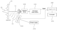
- FIG. 2 is a block diagram of a non-contact thickness measuring system using a laser according to an embodiment of the present invention.
- FIG 3 is an A-scan graph of a 0.5 mm thick PS (polystyrene) sheet according to one embodiment of the present invention.
- FIG. 4 is an A-scan graph of a 1 mm thick PS (polystyrene) sheet according to an embodiment of the present invention.
- FIG. 5 is an A-scan graph of a 1.5 mm thick PS (polystyrene) sheet according to an embodiment of the present invention.
- FIG. 6 is a first graph illustrating the thickness of an object and a tendency of an optical acoustic signal according to an embodiment of the present invention.
- FIG. 7 is a second graph illustrating the thickness of an object and a tendency of an optical acoustic signal according to an embodiment of the present invention.
- FIG. 8 is a flowchart illustrating a non-contact thickness measuring method using a laser according to an embodiment of the present invention.
- FIG. 2 is a view showing the configuration of a non-contact thickness measuring system using a laser according to an embodiment of the present invention.
- a non-contact thickness measuring system using a laser includes a light irradiation unit 100, a receiver 200, a measurement unit 300, an analysis unit 400, and the like. It is done.
- the light irradiator 100 generates a laser 10 using a light source and irradiates the object 20.
- the light irradiator 100 applies the laser 10 to the object to obtain an optical sound signal due to a photoacoustic effect. 20).
- the photoacoustic effect refers to a phenomenon in which a material absorbing electromagnetic wave energy such as light or radio waves generates sound waves by thermal expansion.
- the light irradiator 100 may include a light source for generating the laser 10, and may use a YAG laser that uses YAG (Yttrium Aluminum Garnet) as an oscillation material.
- YAG Yttrium Aluminum Garnet
- the wavelength of the laser 10 may include all of the ultraviolet, infrared and visible light range.
- the receiver 200 corresponds to an acoustic signal detector that detects the optical acoustic signal 40, and receives the optical acoustic signal 40 generated by irradiating an object with the laser 40 generated from the optical irradiator.
- a microphone capable of receiving a range may be used, but is not limited thereto, and may include all equipment from a low frequency detector of kHz to a high frequency detector of MHz.
- the receiver may be connected to a separate power supply 210 for supplying power.
- the object 20 corresponds to an object to be used for measuring thickness, that is, inspection, and may include all of plastic, wood, metal, and rubber sheet.
- the optical acoustic signal 40 may include a primary optical acoustic signal generated by a direct collision between the laser and the object surface, and a secondary optical acoustic signal generated while the laser travels inside the object.
- the measuring unit 300 is a device for measuring the response waveform of the received first optical acoustic signal and the secondary optical acoustic signal, and is a device for indicating a voltage waveform over time to check the operation of the circuit and measure the signal You can use an oscilloscope that corresponds to your basic measurement equipment.
- the measurement unit 300 may be triggered with the light irradiation unit 100. Specifically, the measurement unit 300 triggers a laser irradiation time of the light irradiation unit 100 to respond to the primary optical acoustic signal and the secondary optical acoustic signal. It is possible to measure waveforms stably.
- the analyzer 400 is a device that derives the thickness of the object 20 by analyzing the response characteristics indicated by the measured response waveforms, and may use a computer or the like capable of controlling or measuring signals.
- the primary photoacoustic signal corresponds to a shock wave generated when the laser source 40, which is the source of vibration, reaches the surface of the object 20 and first collides with the object 20 at the point where it is reached. It is a large waveform and shows a tendency to decrease in intensity.
- the secondary optical acoustic signal is generated at a slight time interval from the primary optical acoustic signal and corresponds to a surface wave generated through mechanical excitation after the laser 10 hits the surface of the object 20.
- the response waveform by the primary photoacoustic signal and the response waveform by the secondary photoacoustic signal have a tendency according to the thickness of the object 20. By using this tendency, the thickness of the object 20 can be measured. Do.
- the thickness measurement range can be measured from several hundred micrometers to several millimeters.
- the response characteristics represented by the measured response waveforms include the difference in generation time between the primary optical signal and the secondary optical signal, and the maximum amplitude and duration of each of the primary optical signal and the secondary optical signal. It may include.
- the secondary photoacoustic signal is generated with a slight temporal gap after the generation of the primary photoacoustic signal, and as the thickness of the object increases, the secondary photoacoustic signal and the secondary photoacoustic signal are generated.
- the time difference of occurrence shows a tendency to decrease.
- the voltage waveform over time can be measured, where the primary optical sound signal and the secondary optical sound signal have a maximum amplitude value, respectively, the thickness of the object 20 As becomes larger, the maximum amplitude magnitude of the primary optical acoustic signal decreases and the maximum amplitude magnitude of the secondary optical acoustic signal tends to increase.
- a primary optical acoustic signal is generated and the intensity decreases with time, and as the laser 10 proceeds inside the object 20.
- the intensity increases again.
- the duration of the primary photoacoustic signal decreases and the duration of the secondary photoacoustic signal increases. Indicates.
- Non-contact thickness measuring system using a laser may include an angle adjusting unit 500 for adjusting the irradiation angle of the laser generated from the light irradiation unit 100.
- the angle adjuster 500 is preferably located between the light irradiator 100 and the object 20, and a galvano mirror may be used, but is not limited thereto. And all possible mirrors.
- the angle adjuster 500 may adjust the irradiation angle at which the laser 10 is irradiated onto the object 20 according to the position of the receiver 200 to be installed.
- the design freedom of the thickness measurement system can be greatly improved.
- Figure 3 shows an A-scan graph of a 0.5 mm thick PS (polystyrene) sheet according to an embodiment of the present invention
- Figure 4 is a 1 mm thick PS (polystyrene) sheet according to an embodiment of the present invention
- Figure 5 shows a graph
- Figure 5 shows an A-scan graph of a 1.5 mm thick PS (polystyrene) plate according to an embodiment of the present invention.
- A-scan, B-scan, C-scan, etc. are related to the optical acoustic signal, and A-scan is a waveform analysis performed by pulse-echo or pitch-catch. Means.
- the duration of the primary optical acoustic signal was measured as about 170 ⁇ m to 360 ⁇ m when the object was 0.5 mm, about 160 ⁇ m to 320 ⁇ m when 1 mm, and about 165 to 320 ⁇ m when 1.5 mm. From this measurement result, it can be seen that the duration of the primary photoacoustic signal decreases as the thickness of the object increases.
- the duration range of the secondary photoacoustic signal was measured as about 430 ⁇ m to 650 ⁇ m when the object was 0.5 mm, about 350 ⁇ m to 780 ⁇ m when 1 mm, and about 330 ⁇ m to 1260 ⁇ m when 1.5 mm. It can be seen that the duration of the secondary photoacoustic signal increases as it increases.
- the maximum amplitude of the primary optical acoustic signal decreases and the maximum amplitude of the secondary optical acoustic signal increases, and the primary optical acoustic signal and the secondary optical acoustic sound are increased. It can be seen that the occurrence time difference of the signal decreases.
- FIG. 6 is a first graph illustrating a thickness of an object and a tendency of an optical acoustic signal according to an embodiment of the present invention
- FIG. 7 is a tendency of the thickness and an optical acoustic signal of an object according to an embodiment of the present invention. It is a 2nd graph for showing.
- the rms ratio may be defined by Equation 1 below, and the maximum ratio may be defined by Equation 2 below.
- rms ratio rms value of the secondary optoacoustic signal / rms value of the primary optoacoustic signal
- Maximum value ratio maximum value of the secondary optical signal / maximum value of the primary optical signal
- rms represents a root mean square (rms) value of the optical acoustic signal.
- both the rms ratio and the maximum value ratio have a tendency to increase as the thickness of the object increases, and the thickness of the object can be estimated from this tendency.
- FIG. 8 is a flowchart illustrating a non-contact thickness measuring method using a laser according to an embodiment of the present invention.
- a laser may be irradiated onto a reference specimen using a light source (S10).
- a primary optical acoustic signal generated by a direct collision between the laser and the reference specimen surface and a secondary optical acoustic signal generated while the laser travels inside the object are received (S20).
- a first response waveform of the received primary optical acoustic signal and the secondary optical acoustic signal may be measured (S30).
- the response waveform of the subject After measuring the response waveform of the reference specimen, the response waveform of the subject may be measured as follows, of course, the order of measurement of the reference specimen and the subject may be changed.
- the laser beam can be irradiated to the object under test using a light source (S40).
- a primary optical acoustic signal generated by a direct collision between the laser and the object surface and a secondary optical acoustic signal generated while the laser travels inside the object are received (S50).
- a second response waveform of the received primary optical acoustic signal and the secondary optical acoustic signal may be measured (S60).
- the thickness of the object may be derived by comparing and analyzing the response characteristic represented by the first response waveform and the response characteristic represented by the second response waveform (S70).
- the response characteristic may include a difference in generation time between the primary optical acoustic signal and the secondary optical acoustic signal, and the maximum amplitude and duration of each of the primary optical acoustic signal and the secondary optical acoustic signal.
Landscapes
- Physics & Mathematics (AREA)
- Electromagnetism (AREA)
- General Physics & Mathematics (AREA)
- Engineering & Computer Science (AREA)
- Plasma & Fusion (AREA)
- Optics & Photonics (AREA)
- Length Measuring Devices Characterised By Use Of Acoustic Means (AREA)
- Length Measuring Devices By Optical Means (AREA)
- Investigating Or Analyzing Materials By The Use Of Ultrasonic Waves (AREA)
Abstract
본 발명은 레이저를 이용한 비접촉식 두께 측정 시스템 및 방법에 관한 것으로, 더욱 상세하게는 광원을 이용하여 레이저를 발생시켜 대상체에 조사하기 위한 광 조사부, 상기 레이저와 상기 대상체 표면의 직접적인 충돌에 의해 발생하는 1차 광 음향 신호와 상기 레이저가 상기 대상체 내부를 진행하면서 발생하는 2차 광 음향 신호를 수신하기 위한 수신부, 수신된 상기 1차 광 음향 신호와 상기 2차 광 음향 신호의 응답 파형을 측정하기 위한 측정부 및 상기 측정된 응답 파형이 나타내는 응답 특성을 분석하여 상기 대상체의 두께를 도출하기 위한 분석부를 포함하며, 레이저를 대상체에 조사하여 발생하는 1차 광 음향 신호 및 2차 광 음향 신호의 경향성을 분석함으로써 대상체의 두께를 측정할 수 있는 레이저를 이용한 비접촉식 두께 측정 시스템 및 방법에 관한 것이다.
Description
본 발명은 레이저에서 나오는 광학적 펄스를 이용하며 대상 물체로부터 발생하는 음향신호로부터 대상 물체의 두께를 측정하기 위한 시스템 및 방법에 관한 것이다.
제품을 생산하는 경우 다양한 내부 및 외부 요인에 의해 부재의 물성이 균질하지 않으며 두께 역시 균일성을 가지는 것은 쉽지 않다. 이러한 부재의 불균질성은 제품의 성능을 저하하는 직접적인 원인이 되므로 부재의 균질성은 품질을 결정하는 매우 중요한 특성 중 하나이다.
일반적으로 가전, 자동차, 토목 및 건축 분야 등에서는 기술이 발전함에 따라 판재를 얇게 가공하여 경량화시켜 제품을 생산하고 있다. 이때, 금속판 등을 금형 가공하는 과정에서 특정 부분의 두께가 얇아지는 현상이 발생할 수 있는데, 이는 제품의 품질을 저하하는 요인이 되고 있다.
따라서, 제품의 불량률을 줄이거나 제품 수명 예측을 위해 이러한 두께 불균일성을 검사하는 것이 필요한 실정이다.
도 1은 종래 물질의 두께 및 굴절률을 측정하는 시스템을 나타내기 위한 도면이다.
도 1을 참조하면, 주기적인 간격으로 발진하는 펄스 형태의 레이저를 제공하는 광 조사부 및 상기 광 조사부에서 나오는 레이저 광을 이용하여 측정 물질의 간섭 신호를 측정하고 이를 분석하여 측정 물질의 두께 및 굴절률을 동시에 산출하는 스펙트럼 분석 간섭부로 구성되는 것을 특징으로 한다.
위 기술은 레이저에 물질을 통과한 빛을 간섭계에 통과시켜 대상 물질의 두께를 측정하는 시스템이기 때문에 간섭계라는 고가의 장비가 추가적으로 필요하며 표면이 매끄럽고 우수하며 광학적인 투과성을 갖는 경면 물질에만 국한되어 측정할 수 있기 때문에 적용물질의 범위가 좁은 한계가 있다.
또한, 위 기술은 매우 얇은 두께만 측정할 수 있어 수 mm 두께 범위의 측정이 불가능하며, 대형 와이퍼를 한 번에 실시간으로 측정하기 위해서는 상기 스펙트럼 분석 간섭부를 측정 영역을 넓히기 위해 대형 광학계 측정용으로 구성해야 하며 면적 광 검출기를 더 구비해야 하는 번거로움이 있다.
상기와 같은 문제를 해결하기 위한 본 발명은 레이저를 대상체에 조사하여 발생하는 1차 광 음향 신호 및 2차 광 음향 신호의 경향성을 분석함으로써 대상체의 두께를 측정할 수 있는 레이저를 이용한 비접촉식 두께 측정 시스템 및 방법을 제공하고자 함에 있다.
상기와 같은 목적을 달성하기 위한 본 발명의 일 실시예에 의한 비접촉식 두께 측정 시스템은 광원을 이용하여 레이저를 발생시켜 대상체에 조사하기 위한 광 조사부, 상기 레이저와 상기 대상체 표면의 직접적인 충돌에 의해 발생하는 1차 광 음향 신호와 상기 레이저가 상기 대상체 내부를 진행하면서 발생하는 2차 광 음향 신호를 수신하기 위한 수신부, 수신된 상기 1차 광 음향 신호와 상기 2차 광 음향 신호의 응답 파형을 측정하기 위한 측정부 및 상기 측정된 응답 파형이 나타내는 응답 특성을 분석하여 상기 대상체의 두께를 도출하기 위한 분석부를 포함하는 것을 특징으로 한다.
또한, 본 발명의 일 실시예에 의한 상기 2차 광 음향 신호는 상기 대상체의 물리적 진동에 의해 발생하는 것을 특징으로 한다.
또한, 본 발명의 일 실시예에 의한 비접촉식 두께 측정 시스템은 상기 광 조사부에서 발생한 레이저의 조사 각도를 조절하기 위한 각도 조절부를 포함하는 것을 특징으로 한다.
또한, 본 발명의 일 실시예에 의한 상기 각도 조절부는 상기 수신부의 위치에 따라 상기 레이저가 대상체에 조사되는 조사 각도를 조절하는 것을 특징으로 한다.
또한, 본 발명의 일 실시예에 의한 상기 측정부는 상기 광 조사부의 레이저 조사 시점을 트리거링하여 상기 1차 광 음향 신호와 상기 2차 광 음향 신호의 응답 파형을 안정적으로 측정하는 것을 특징으로 한다.
또한, 본 발명의 일 실시예에 의한 상기 응답특성은 상기 1차 광 음향 신호와 상기 2차 광 음향 신호의 발생 시간 차이와, 상기 1차 광 음향 신호와 상기 2차 광 음향 신호 각각의 최대 진폭 크기 및 지속 시간을 포함하는 것을 특징으로 한다.
또한, 본 발명의 일 실시예에 의한 비접촉식 두께 측정 시스템은 상기 대상체의 두께가 커짐에 따라 상기 1차 광 음향 신호와 상기 2차 광 음향 신호의 발생 시간 차이는 감소하는 것을 특징으로 한다.
또한, 본 발명의 일 실시예에 의한 비접촉식 두께 측정 시스템은 상기 대상체의 두께가 커짐에 따라 상기 1차 광 음향 신호의 최대 진폭 크기는 감소하고 상기 2차 광 음향 신호의 최대 진폭 크기는 증가하는 것을 특징으로 한다.
또한, 본 발명의 일 실시예에 의한 비접촉식 두께 측정 시스템은 상기 대상체의 두께가 커짐에 따라 상기 1차 광 음향 신호의 지속 시간은 감소하고 상기 2차 광 음향 신호의 지속 시간은 증가하는 것을 특징으로 한다.
상기와 같은 목적을 달성하기 위한 본 발명의 일 실시예에 의한 비접촉식 두께 측정 방법은 광원을 이용하여 레이저를 기준 시편에 조사하는 단계, 상기 레이저와 상기 기준 시편 표면의 직접적인 충돌에 의해 발생하는 1차 광 음향 신호와 상기 레이저가 상기 대상체 내부를 진행하면서 발생하는 2차 광 음향 신호를 수신하는 단계, 수신된 상기 1차 광 음향 신호와 상기 2차 광 음향 신호의 제1 응답 파형을 측정하는 단계, 광원을 이용하여 레이저를 대상체에 조사하는 단계, 상기 레이저와 상기 대상체 표면의 직접적인 충돌에 의해 발생하는 1차 광 음향 신호와 상기 레이저가 상기 대상체 내부를 진행하면서 발생하는 2차 광 음향 신호를 수신하는 단계, 수신된 상기 1차 광 음향 신호와 상기 2차 광 음향 신호의 제2 응답 파형을 측정하는 단계 및 상기 제1 응답 파형이 나타내는 응답 특성과 상기 제2 응답 파형이 나타내는 응답 특성을 비교 분석하여 상기 대상체의 두께를 도출하는 단계를 포함하는 것을 특징으로 한다.
또한, 본 발명의 일 실시예에 의한 상기 응답 파형의 rms비는 하기 수식 1과 같이 나타낼 수 있으며, 상기 rms비는 대상체의 두께가 커질수록 증가하는 것을 특징으로 한다.
[수식 1]
rms 비 = 2차 광 음향 신호의 rms 값 / 1차 광 음향 신호의 rms 값
또한, 본 발명의 일 실시예에 의한 상기 응답 파형의 최대값 비는 하기 수식 2와 같이 나타낼 수 있으며, 상기 최대값비는 대상체의 두께가 커질수록 증가하는 것을 특징으로 한다.
[수식 2]
최대값 비 = 2차 광 음향 신호의 최대값 / 1차 광 음향 신호의 최대값
본 발명에 따른 비접촉식 두께 측정 시스템 및 방법은 고무, 목재, 플라스틱이나 금속 등 다양한 재질의 판재에 적용 가능하며, 두께 측정의 범위는 수백 마이크로미터부터 수 밀리미터 단위까지 측정 가능한 이점이 있다.
또한, 빛을 발산시키는 장비와 음파 탐지기기, 파형 측정기기만으로 진동 특성을 갖는 여러 물질의 두께를 측정할 수 있는 장점이 있다.
게다가, 넓은 영역의 스캐닝에도 레이저 검류계를 이용하여 단기간에 측정이 가능하며, 공기 중에서 비접촉식으로 사용 가능하여 사용 제약이 적은 효과가 있다.
도 1은 종래 물질의 두께 및 굴절률을 측정하는 시스템을 나타내기 위한 도면이다.
도 2는 본 발명의 일 실시예에 의한 레이저를 이용한 비접촉식 두께 측정 시스템의 구성도이다.
도 3은 본 발명의 일 실시예에 의해 0.5mm 두께의 PS(폴리스티렌) 판재의 A-scan 그래프이다.
도 4는 본 발명의 일 실시예에 의해 1mm 두께의 PS(폴리스티렌) 판재의 A-scan 그래프이다.
도 5는 본 발명의 일 실시예에 의해 1.5mm 두께의 PS(폴리스티렌) 판재의 A-scan 그래프이다.
도 6은 본 발명의 일 실시예에 따른 대상체의 두께와 광 음향 신호의 경향성을 나타내기 위한 제1 그래프이다.
도 7은 본 발명의 일 실시예에 따른 대상체의 두께와 광 음향 신호의 경향성을 나타내기 위한 제2 그래프이다.
도 8은 본 발명의 일 실시예에 따른 레이저를 이용한 비접촉식 두께 측정 방법의 흐름도이다.
*도면 중 주요 부호에 대한 설명
10: 레이저
20: 대상체
30: 진동파의 파형
40: 광 음향 신호
100: 광 조사부
200: 수신부
210: 전력공급원
300: 측정부
400: 분석부
500: 각도 조절부
본 발명의 이점 및 특징, 그리고 그것을 달성하는 방법은 첨부된 도면과 함께 상세하게 후술되어 있는 실시예들을 참조하면 명확해질 것이다.
그러나 본 발명은 이하에 개시되는 실시예들에 의해 한정되는 것이 아니라 서로 다른 다양한 형태로 구현될 것이며, 단지 본 실시예들은 본 발명의 개시가 완전하도록 하며, 본 발명이 속하는 기술분야에서 통상의 지식을 가진 자에게 발명의 범주를 완전하게 알려주기 위해 제공되는 것이며, 본 발명은 청구항의 범주에 의해 정의될 뿐이다. 명세서 전체에 걸쳐 동일 참조 부호는 동일 구성요소를 지칭한다.
이하에서는 첨부된 도면을 참조하여 본 발명의 실시예들을 상세히 설명하기로 한다.
도 2는 본 발명의 일 실시예에 의한 레이저를 이용한 비접촉식 두께 측정 시스템의 구성도를 나타내는 도면이다.
도 2를 참조하면, 본 발명의 일 실시예에 의한 레이저를 이용한 비접촉식 두께 측정 시스템은 광 조사부(100), 수신부(200), 측정부(300) 및 분석부(400) 등을 포함하는 것을 특징으로 한다.
광 조사부(100)는 광원을 이용하여 레이저(10)를 발생시켜 대상체(20)에 조사하는 장치이며, 광 음향 효과(photoacoustic effect)에 의한 광 음향 신호를 획득하기 위해 레이저(10)를 대상체(20)에 조사할 수 있다. 이때, 광 음향 효과란 빛이나 라디오파와 같은 전자기파 에너지를 흡수한 물질이 열 팽창함으로써 음파를 발생시키는 현상을 의미한다.
광 조사부(100)는 레이저(10)를 발생시키기 위한 광원을 포함하며, 발진 물질로서 YAG(Yttrium Aluminium Garnet)를 이용하는 YAG 레이저를 사용할 수 있다. 이때, 레이저 발진효율을 높이기 위해 Nd가 도핑된 Nd-YAG 레이저를 사용하는 것이 바람직하나, 이에 제한되는 것은 아니며, 레이저 및 다이오드 등과 같은 특정 주파수의 빛을 발산하는 모든 장비를 포함할 수 있다.
레이저(10)의 파장은 자외선, 적외선 및 가시광선 범위를 모두 포함할 수 있음을 물론이다.
수신부(200)는 광 음향 신호(40)를 검출하는 음향신호 검출기기에 해당하며, 광 조사부로부터 발생한 레이저(40)가 대상체에 조사됨으로써 발생하는 광 음향 신호(40)를 수신하는데, 초음파 영역 주파수 범위의 수신이 가능한 마이크로폰 등을 사용할 수 있으나, 이에 제한되는 것은 아니며, kHz 단위인 저주파 탐지기기로부터 MHz 단위인 고주파 탐지기기까지의 장비를 모두 포함할 수 있다.
응향신호 검출기기의 전력공급원으로서, 상기 수신부는 전력을 공급하기 위한 별도의 전력공급원(210)이 연결될 수 있다.
대상체(20)는 두께 측정 즉, 검사에 사용되는 대상 물체에 해당하며, 플라스틱, 나무, 금속 및 고무 판재 등을 모두 포함할 수 있다.
광 음향 신호(40)는 상기 레이저와 상기 대상체 표면의 직접적인 충돌에 의해 발생하는 1차 광 음향 신호와 상기 레이저가 상기 대상체 내부를 진행하면서 발생하는 2차 광 음향 신호를 포함할 수 있다.
측정부(300)는 수신된 상기 1차 광 음향 신호와 상기 2차 광 음향 신호의 응답 파형을 측정하는 장치이며, 시간에 따른 전압 파형을 나타내기 위한 장비로서 회로의 동작을 검사하고 신호를 측정하기 위한 기본적인 측정 장비에 해당하는 오실로스코프를 사용할 수 있다.
측정부(300)는 광 조사부(100)와 트리거될 수 있는데, 구체적으로 상기 광 조사부(100)의 레이저 조사 시점을 트리거링(trigerring)하여 상기 1차 광 음향 신호와 상기 2차 광 음향 신호의 응답 파형을 안정적으로 측정하는 것이 가능하다.
분석부(400)는 상기 측정된 응답 파형이 나타내는 응답 특성을 분석하여 상기 대상체(20)의 두께를 도출하는 장치이며, 신호들을 제어하거나 계측할 수 있는 컴퓨터 등을 사용할 수 있다.
1차 광 음향 신호는 진동의 가진원인 레이저(40)가 대상체(20)의 표면에 도달하면 도달된 지점에서 대상체(20)와 처음으로 충돌할 때 생성되는 충격파에 해당하며 파형의 개형은 초기에 큰 파형이 되고 점점 세기가 줄어드는 경향을 나타낸다.
2차 광 음향 신호는 상기 1차 광 음향 신호와 약간의 시간적 간격을 두고 발생하며 레이저(10)가 대상체(20)의 표면에 충돌된 이후 기계적인 가진을 통해 생성되는 표면파에 해당한다.
이러한 1차 광 음향 신호에 의한 응답 파형과 2차 광 음향 신호에 의한 응답 파형은 대상체(20)의 두께에 따른 경향성을 가지는데, 이러한 경향성을 이용함으로써 대상체(20)의 두께를 측정하는 것이 가능하다.
특히, 낮은 경도와 강성을 가진 물질과 주로 산업체에 사용되는 높은 경도와 강성을 가진 물질 등 재질에 관계없이 유사한 경향성을 나타내고 있는바, 고무, 목재, 플라스틱이나 금속 등 다양한 재질의 판재에도 적용 가능하며, 두께 측정의 범위는 수백 마이크로미터부터 수 밀리미터 단위까지 측정 가능한 이점이 있다.
측정된 응답 파형이 나타내는 응답특성은 상기 1차 광 음향 신호와 상기 2차 광 음향 신호의 발생 시간 차이와, 상기 1차 광 음향 신호와 상기 2차 광 음향 신호 각각의 최대 진폭 크기 및 지속 시간을 포함할 수 있다.
구체적으로, 2차 광 음향 신호는 1차 광 음향 신호 발생 후 약간의 시간적 갭(gap)을 두고 발생하게 되는데, 대상체의 두께가 커짐에 따라 상기 1차 광 음향 신호와 상기 2차 광 음향 신호의 발생 시간 차이는 감소하는 경향성을 나타낸다.
또한, 측정부(300)에 해당하는 오실로스코프에서는 시간에 따른 전압 파형이 측정될 수 있으며, 여기서 1차 광 음향 신호 및 2차 광 음향 신호는 각각 최대 진폭값을 가지게 되는데, 대상체(20)의 두께가 커짐에 따라 상기 1차 광 음향 신호의 최대 진폭 크기는 감소하고 상기 2차 광 음향 신호의 최대 진폭 크기는 증가하는 경향성을 나타낸다.
또한, 레이저(10)가 대상체(20)와 처음으로 충돌할 때 1차 광 음향 신호가 발생하게 되며 시간이 지남에 따라 점점 세기가 줄어들고, 레이저(10)가 대상체(20) 내부로 진행함에 따라 2차 광 음향 신호가 발생하면서 다시 세기가 커지게 되는데, 대상체(20)의 두께가 커짐에 따라 상기 1차 광 음향 신호의 지속 시간은 감소하고 상기 2차 광 음향 신호의 지속 시간은 증가하는 경향성을 나타낸다.
본 발명의 일 실시예에 의한 레이저를 이용한 비접촉식 두께 측정 시스템은 상기 광 조사부(100)에서 발생한 레이저의 조사 각도를 조절하기 위한 각도 조절부(500)를 포함할 수 있다.
각도 조절부(500)는 바람직하게 상기 광 조사부(100)와 상기 대상체(20) 사이에 위치하며, 갈바노 미러(galvano mirror) 등이 사용될 수 있으나 이에 한정되는 것은 아니며 레이저의 조사 각도의 조절이 가능한 모든 미러 등을 포함할 수 있다.
각도 조절부(500)는 설치되는 수신부(200)의 위치에 따라 상기 레이저(10)가 대상체(20)에 조사되는 조사 각도를 조절할 수 있는바, 본 발명의 일 실시예에 의한 레이저를 이용한 비접촉식 두께 측정 시스템의 설계 자유도를 크게 향상시킬 수 있다.
이하에서는 본 발명의 실시예를 통하여 본 발명에 따른 레이저를 이용한 비접촉식 두께 측정 시스템에 대해 더욱 상세하게 설명한다. 그러나, 이들 실시예는 본 발명을 예시적으로 설명하기 위한 것으로 본 발명의 범위가 이들 실시예에 한정되는 것은 아니다.
광 조사부는 빛을 발생시키기 위한 가진원인 YAG 레이저를 사용하였으며, 10Hz 주파수, 532 nm파장, 7ns 펄스 지속시간으로 설정하였으며, 대상체로는 PS(폴리스티렌) 판재를 사용하으며, 대상체의 두께를 변화시키면서 광 음향 신호를 측정하였다.
도 3은 본 발명의 일 실시예에 의해 0.5mm 두께의 PS(폴리스티렌) 판재의 A-scan 그래프를 나타낸 것이고, 도 4는 본 발명의 일 실시예에 의해 1mm 두께의 PS(폴리스티렌) 판재의 A-scan 그래프를 나타낸 것이고, 도 5는 본 발명의 일 실시예에 의해 1.5mm 두께의 PS(폴리스티렌) 판재의 A-scan 그래프를 나타낸 것이다.
일반적으로 광 음향 신호 관련 기술로는 A-scan, B-scan, C-scan 등의 기법이 있는데, A-scan은 펄스에코(pulse-echo) 혹은 피치케치(pitch-catch)를 수행한 파형 분석을 의미한다.
도 3 내지 도 5를 참조하면, 1차 광 음향 신호의 지속시간 범위는 대상체가 0.5mm인 경우 약 170μm~360μm, 1mm인 경우 약 160μm~320μm, 1.5mm인 경우 약 165~320μm로 측정되었는바, 이 측정결과로부터 대상체의 두께가 커짐에 따라 1차 광 음향 신호의 지속시간은 감소하는 것을 알 수 있다.
2차 광 음향 신호의 지속시간 범위는 대상체가 0.5mm인 경우 약 430μm~650μm, 1mm인 경우 약 350μm~780μm, 1.5mm인 경우 약 330μm~1260μm로 측정되었는바, 이 측정결과로부터 대상체의 두께가 커짐에 따라 2차 광 음향 신호의 지속시간은 증가하는 것을 알 수 있다.
또한, 대상체의 두께가 커짐에 따라, 1차 광 음향 신호의 최대 진폭 크기는 감소하며, 2차 광 음향 신호의 최대 진폭 크기는 증가하는 것을 알 수 있으며, 1차 광 음향 신호와 2차 광 음향 신호의 발생 시간 차이가 감소하는 것을 알 수 있다.
위와 같이, 대상체의 두께와 광 음향 신호가 나타내는 응답특성은 매우 강한 상관 관계가 있으며, 이러한 상관 관계를 분석함으로써 대상체의 절대적인 두께 혹은 기준 시편과의 상대적인 두께를 측정하는 것이 가능하다.
도 6은 본 발명의 일 실시예에 따른 대상체의 두께와 광 음향 신호의 경향성을 나타내기 위한 제1 그래프이고, 도 7은 본 발명의 일 실시예에 따른 대상체의 두께와 광 음향 신호의 경향성을 나타내기 위한 제2 그래프이다.
여기서, rms 비(rms ratio)는 하기 수식 1로 정의되며, 최대값 비(max ratio)는 하기 수식 2로 정의될 수 있다.
[수식 1]
rms 비 = 2차 광 음향 신호의 rms 값 / 1차 광 음향 신호의 rms 값
[수식 2]
최대값 비 = 2차 광 음향 신호의 최대값 / 1차 광 음향 신호의 최대값
이때, rms는 광 음향 신호의 rms(root mean square) 값을 나타낸다.
상기 도면을 참조하면, 상기 rms 비와 상기 최대값 비는 모두 대상체의 두께가 커질수록 증가하는 경향성을 나타냄을 알 수 있으며, 이러한 경향성으로부터 대상체의 두께를 추정할 수 있다.
도 8은 본 발명의 일 실시예에 따른 레이저를 이용한 비접촉식 두께 측정 방법의 흐름도이다.
도 8을 참조하면, 먼저 광원을 이용하여 레이저를 기준 시편에 조사할 수 있다(S10).
그 다음, 상기 레이저와 상기 기준 시편 표면의 직접적인 충돌에 의해 발생하는 1차 광 음향 신호와 상기 레이저가 상기 대상체 내부를 진행하면서 발생하는 2차 광 음향 신호를 수신한다(S20).
그 후, 수신된 상기 1차 광 음향 신호와 상기 2차 광 음향 신호의 제1 응답 파형을 측정할 수 있다(S30).
기준 시편의 응답 파형 측정 후 아래와 같이 피검사체의 응답 파형을 측정할 수 있는데, 기준 시편과 피검사체의 측정 순서는 바뀔 수 있음은 물론이다.
구체적으로, 광원을 이용하여 레이저를 피검사체의 조사할 수 있다(S40).
그 다음, 상기 레이저와 상기 대상체 표면의 직접적인 충돌에 의해 발생하는 1차 광 음향 신호와 상기 레이저가 상기 대상체 내부를 진행하면서 발생하는 2차 광 음향 신호를 수신한다(S50).
그 후, 수신된 상기 1차 광 음향 신호와 상기 2차 광 음향 신호의 제2 응답 파형을 측정할 수 있다(S60).
최종적으로, 상기 제1 응답 파형이 나타내는 응답 특성과 상기 제2 응답 파형이 나타내는 응답 특성을 비교 분석하여 상기 대상체의 두께를 도출할 수 있다(S70).
이때, 응답 특성은 상기 1차 광 음향 신호와 상기 2차 광 음향 신호의 발생 시간 차이와, 상기 1차 광 음향 신호와 상기 2차 광 음향 신호 각각의 최대 진폭 크기 및 지속 시간을 포함할 수 있다.
이상에서, 본 발명에 따른 실시예를 구성하는 모든 구성 요소들이 하나로 결합하거나 결합하여 동작하는 것으로 설명되었다고 해서, 본 발명이 반드시 이러한 실시예에 한정되는 것은 아니다. 즉, 본 발명의 목적 범위 안에서라면, 그 모든 구성 요소들이 하나 이상으로 선택적으로 결합하여 동작할 수도 있다. 또한, 이상에서 기재된 "포함하다", "구성하다" 또는 "가지다" 등의 용어는, 특별히 반대되는 기재가 없는 한, 해당 구성 요소가 내재할 수 있음을 의미하는 것이므로, 다른 구성 요소를 제외하는 것이 아니라 다른 구성 요소를 더 포함할 수 있는 것으로 해석되어야 한다. 기술적이거나 과학적인 용어를 포함한 모든 용어들은, 다르게 정의되지 않는 한, 본 발명이 속하는 기술 분야에서 통상의 지식을 가진 자에 의해 일반적으로 이해되는 것과 동일한 의미가 있다. 사전에 정의된 용어와 같이 일반적으로 사용되는 용어들은 관련 기술의 문맥상의 의미와 일치하는 것으로 해석되어야 하며, 본 발명에서 명백하게 정의하지 않는 한, 이상적이거나 과도하게 형식적인 의미로 해석되지 않는다.
Claims (13)
- 광원을 이용하여 레이저를 발생시켜 대상체에 조사하기 위한 광 조사부;상기 레이저와 상기 대상체 표면의 직접적인 충돌에 의해 발생하는 1차 광 음향 신호와 상기 레이저가 상기 대상체 내부를 진행하면서 발생하는 2차 광 음향 신호를 수신하기 위한 수신부;수신된 상기 1차 광 음향 신호와 상기 2차 광 음향 신호의 응답 파형을 측정하기 위한 측정부; 및상기 측정된 응답 파형이 나타내는 응답 특성을 분석하여 상기 대상체의 두께를 도출하기 위한 분석부를 포함하는 것을 특징으로 하는 레이저를 이용한 비접촉식 두께 측정 시스템.
- 제1항에 있어서,상기 2차 광 음향 신호는 상기 대상체의 물리적 진동에 의해 발생하는 것을 특징으로 하는 레이저를 이용한 비접촉식 두께 측정 시스템.
- 제1항에 있어서,상기 광 조사부에서 발생한 레이저의 조사 각도를 조절하기 위한 각도 조절부를 포함하는 것을 특징으로 하는 레이저를 이용한 비접촉식 두께 측정 시스템.
- 제3항에 있어서,상기 각도 조절부는 상기 수신부의 위치에 따라 상기 레이저가 대상체에 조사되는 조사 각도를 조절하는 것을 특징으로 하는 레이저를 이용한 비접촉식 두께 측정 시스템.
- 제1항에 있어서,상기 측정부는 상기 광 조사부의 레이저 조사 시점을 트리거링하여 상기 1차 광 음향 신호와 상기 2차 광 음향 신호의 응답 파형을 안정적으로 측정하는 것을 특징으로 하는 레이저를 이용한 비접촉식 두께 측정 시스템.
- 제1항에 있어서,상기 응답특성은,상기 1차 광 음향 신호와 상기 2차 광 음향 신호의 발생 시간 차이와, 상기 1차 광 음향 신호와 상기 2차 광 음향 신호 각각의 최대 진폭 크기 및 지속 시간을 포함하는 것을 특징으로 하는 레이저를 이용한 비접촉식 두께 측정 시스템.
- 제6항에 있어서,상기 대상체의 두께가 커짐에 따라 상기 1차 광 음향 신호와 상기 2차 광 음향 신호의 발생 시간 차이는 감소하는 것을 특징으로 하는 레이저를 이용한 비접촉식 두께 측정 시스템.
- 제6항에 있어서,상기 대상체의 두께가 커짐에 따라 상기 1차 광 음향 신호의 최대 진폭 크기는 감소하고 상기 2차 광 음향 신호의 최대 진폭 크기는 증가하는 것을 특징으로 하는 레이저를 이용한 비접촉식 두께 측정 시스템.
- 제6항에 있어서,상기 대상체의 두께가 커짐에 따라 상기 1차 광 음향 신호의 지속 시간은 감소하고 상기 2차 광 음향 신호의 지속 시간은 증가하는 것을 특징으로 하는 레이저를 이용한 비접촉식 두께 측정 시스템.
- 광원을 이용하여 레이저를 기준 시편에 조사하는 단계;상기 레이저와 상기 기준 시편 표면의 직접적인 충돌에 의해 발생하는 1차 광 음향 신호와 상기 레이저가 상기 대상체 내부를 진행하면서 발생하는 2차 광 음향 신호를 수신하는 단계;수신된 상기 1차 광 음향 신호와 상기 2차 광 음향 신호의 제1 응답 파형을 측정하는 단계;광원을 이용하여 레이저를 대상체에 조사하는 단계;상기 레이저와 상기 대상체 표면의 직접적인 충돌에 의해 발생하는 1차 광 음향 신호와 상기 레이저가 상기 대상체 내부를 진행하면서 발생하는 2차 광 음향 신호를 수신하는 단계;수신된 상기 1차 광 음향 신호와 상기 2차 광 음향 신호의 제2 응답 파형을 측정하는 단계; 및상기 제1 응답 파형이 나타내는 응답 특성과 상기 제2 응답 파형이 나타내는 응답 특성을 비교 분석하여 상기 대상체의 두께를 도출하는 단계를 포함하는 것을 특징으로 하는 레이저를 이용한 비접촉식 두께 측정 방법.
- 제10항에 있어서,상기 응답특성은,상기 1차 광 음향 신호와 상기 2차 광 음향 신호의 발생 시간 차이와, 상기 1차 광 음향 신호와 상기 2차 광 음향 신호 각각의 최대 진폭 크기 및 지속 시간을 포함하는 것을 특징으로 하는 레이저를 이용한 비접촉식 두께 측정 방법.
- 제10항에 있어서,상기 응답 파형의 rms비는 하기 수식 1과 같이 나타낼 수 있으며, 상기 rms비는 대상체의 두께가 커질수록 증가하는 것을 특징으로 하는 레이저를 이용한 비접촉식 두께 측정 방법.[수식 1]rms 비 = 2차 광 음향 신호의 rms 값 / 1차 광 음향 신호의 rms 값
- 제10항에 있어서,상기 응답 파형의 최대값 비는 하기 수식 2와 같이 나타낼 수 있으며, 상기 최대값비는 대상체의 두께가 커질수록 증가하는 것을 특징으로 하는 레이저를 이용한 비접촉식 두께 측정 방법.[수식 2]최대값 비 = 2차 광 음향 신호의 최대값 / 1차 광 음향 신호의 최대값
Applications Claiming Priority (2)
| Application Number | Priority Date | Filing Date | Title |
|---|---|---|---|
| KR10-2016-0031024 | 2016-03-15 | ||
| KR1020160031024A KR101794716B1 (ko) | 2016-03-15 | 2016-03-15 | 레이저를 이용한 비접촉식 두께 측정 시스템 및 방법 |
Publications (1)
| Publication Number | Publication Date |
|---|---|
| WO2017160082A1 true WO2017160082A1 (ko) | 2017-09-21 |
Family
ID=59851980
Family Applications (1)
| Application Number | Title | Priority Date | Filing Date |
|---|---|---|---|
| PCT/KR2017/002804 Ceased WO2017160082A1 (ko) | 2016-03-15 | 2017-03-15 | 레이저를 이용한 비접촉식 두께 측정 시스템 및 방법 |
Country Status (2)
| Country | Link |
|---|---|
| KR (1) | KR101794716B1 (ko) |
| WO (1) | WO2017160082A1 (ko) |
Families Citing this family (2)
| Publication number | Priority date | Publication date | Assignee | Title |
|---|---|---|---|---|
| KR102720154B1 (ko) | 2018-12-27 | 2024-10-21 | 삼성전자주식회사 | 하부막 두께의 비파괴적 측정 방법 |
| KR102231162B1 (ko) * | 2019-07-10 | 2021-03-24 | 세메스 주식회사 | 기판 처리 장치 |
Citations (5)
| Publication number | Priority date | Publication date | Assignee | Title |
|---|---|---|---|---|
| JP2001091213A (ja) * | 1999-09-27 | 2001-04-06 | Toshiba Corp | レーザ測距装置および板厚測定装置 |
| JP2001311615A (ja) * | 2000-04-28 | 2001-11-09 | Nkk Corp | 非接触超音波厚さ測定方法及び非接触超音波厚さ測定装置 |
| JP2002213936A (ja) * | 2000-11-16 | 2002-07-31 | Kawasaki Steel Corp | 材料厚さの非接触測定方法及び装置 |
| JP2007322126A (ja) * | 2006-05-30 | 2007-12-13 | Daido Steel Co Ltd | 厚み測定装置 |
| KR20130088916A (ko) * | 2012-01-31 | 2013-08-09 | 주식회사 미루시스템즈 | 레이저간섭계를 이용한 두께측정방법 |
Family Cites Families (1)
| Publication number | Priority date | Publication date | Assignee | Title |
|---|---|---|---|---|
| JP5574724B2 (ja) | 2010-01-27 | 2014-08-20 | キヤノン株式会社 | 被検体情報処理装置および被検体情報処理方法 |
-
2016
- 2016-03-15 KR KR1020160031024A patent/KR101794716B1/ko not_active Expired - Fee Related
-
2017
- 2017-03-15 WO PCT/KR2017/002804 patent/WO2017160082A1/ko not_active Ceased
Patent Citations (5)
| Publication number | Priority date | Publication date | Assignee | Title |
|---|---|---|---|---|
| JP2001091213A (ja) * | 1999-09-27 | 2001-04-06 | Toshiba Corp | レーザ測距装置および板厚測定装置 |
| JP2001311615A (ja) * | 2000-04-28 | 2001-11-09 | Nkk Corp | 非接触超音波厚さ測定方法及び非接触超音波厚さ測定装置 |
| JP2002213936A (ja) * | 2000-11-16 | 2002-07-31 | Kawasaki Steel Corp | 材料厚さの非接触測定方法及び装置 |
| JP2007322126A (ja) * | 2006-05-30 | 2007-12-13 | Daido Steel Co Ltd | 厚み測定装置 |
| KR20130088916A (ko) * | 2012-01-31 | 2013-08-09 | 주식회사 미루시스템즈 | 레이저간섭계를 이용한 두께측정방법 |
Also Published As
| Publication number | Publication date |
|---|---|
| KR20170107274A (ko) | 2017-09-25 |
| KR101794716B1 (ko) | 2017-11-07 |
Similar Documents
| Publication | Publication Date | Title |
|---|---|---|
| CN102395872B (zh) | 超声波检测系统 | |
| CN110763764A (zh) | 一种金属内部缺陷的新型超声检测系统 | |
| CN101871894B (zh) | 利用闪频检测实现材料内部缺陷的动态加载成像表征方法 | |
| WO2017160082A1 (ko) | 레이저를 이용한 비접촉식 두께 측정 시스템 및 방법 | |
| CN102866144A (zh) | 固体材料表面疲劳裂纹的无损检测方法 | |
| US20210396508A1 (en) | Method and device for in situ process monitoring | |
| WO2020134846A1 (zh) | 基于太赫兹的水蒸气检测系统及检测方法 | |
| CN211179651U (zh) | 一种金属内部缺陷的新型超声检测系统 | |
| CN107830810A (zh) | 一种涂层厚度的测量方法及测量系统 | |
| CN112378930A (zh) | 一种基于脉冲激光的熔覆层表面及深层瑕疵检测方法 | |
| CN105301097B (zh) | 一种激光超声激发与检测系统及其检测方法 | |
| Pupeza et al. | Field-resolved spectroscopy in the molecular fingerprint region | |
| WO2011162566A2 (ko) | 실리콘 웨이퍼의 비아홀 측정 장치 및 방법 | |
| EP1460410A4 (en) | SCANNING PROBE MICROSCOPE DEVICE WITH DELAY TIME MODULATION AND FEMTOSE CUSTOM TIME RESOLUTION | |
| CN112098336A (zh) | 激光超声扫描成像装置以及激光超声扫描成像系统 | |
| CN212340975U (zh) | 集清洗、抛光及超声检测于一体的激光复合系统 | |
| CN116124272A (zh) | 一种基于频域干涉的全光纤振动测量方法及系统 | |
| Kaniak et al. | Enhanced non-contact ultrasonic testing using an air-coupled optical microphone | |
| Grégoire et al. | Nonlinear photothermal and photoacoustic processes for crack detection | |
| JPH11304768A (ja) | 剥離検知装置及び方法 | |
| SE1551214A1 (en) | Method and system for inspecting plate-like structures using ultrasound | |
| Sugimoto et al. | Study on concrete internal defect detection from a moving cart equipped with LDVs and a sound source | |
| CN204730935U (zh) | 基于超声波外调制的激光干涉振动检测装置 | |
| KR20020011662A (ko) | 레이저 유도 초음파를 이용하여 금속재의 내부 결함을측정하는 방법 | |
| CN207183795U (zh) | 一种激光信号发生器 |
Legal Events
| Date | Code | Title | Description |
|---|---|---|---|
| NENP | Non-entry into the national phase |
Ref country code: DE |
|
| 121 | Ep: the epo has been informed by wipo that ep was designated in this application |
Ref document number: 17766983 Country of ref document: EP Kind code of ref document: A1 |
|
| 122 | Ep: pct application non-entry in european phase |
Ref document number: 17766983 Country of ref document: EP Kind code of ref document: A1 |