WO2017159532A1 - 高エネルギービーム溶接品質判定方法、その判定方法を利用した品質判定装置、その判定方法を利用した溶接管理システム - Google Patents
高エネルギービーム溶接品質判定方法、その判定方法を利用した品質判定装置、その判定方法を利用した溶接管理システム Download PDFInfo
- Publication number
- WO2017159532A1 WO2017159532A1 PCT/JP2017/009468 JP2017009468W WO2017159532A1 WO 2017159532 A1 WO2017159532 A1 WO 2017159532A1 JP 2017009468 W JP2017009468 W JP 2017009468W WO 2017159532 A1 WO2017159532 A1 WO 2017159532A1
- Authority
- WO
- WIPO (PCT)
- Prior art keywords
- welding
- high energy
- energy beam
- molten pool
- quality
- Prior art date
- Legal status (The legal status is an assumption and is not a legal conclusion. Google has not performed a legal analysis and makes no representation as to the accuracy of the status listed.)
- Ceased
Links
Images




Classifications
-
- B—PERFORMING OPERATIONS; TRANSPORTING
- B23—MACHINE TOOLS; METAL-WORKING NOT OTHERWISE PROVIDED FOR
- B23K—SOLDERING OR UNSOLDERING; WELDING; CLADDING OR PLATING BY SOLDERING OR WELDING; CUTTING BY APPLYING HEAT LOCALLY, e.g. FLAME CUTTING; WORKING BY LASER BEAM
- B23K31/00—Processes relevant to this subclass, specially adapted for particular articles or purposes, but not covered by any single one of main groups B23K1/00 - B23K28/00
- B23K31/12—Processes relevant to this subclass, specially adapted for particular articles or purposes, but not covered by any single one of main groups B23K1/00 - B23K28/00 relating to investigating the properties, e.g. the weldability, of materials
- B23K31/125—Weld quality monitoring
-
- B—PERFORMING OPERATIONS; TRANSPORTING
- B23—MACHINE TOOLS; METAL-WORKING NOT OTHERWISE PROVIDED FOR
- B23K—SOLDERING OR UNSOLDERING; WELDING; CLADDING OR PLATING BY SOLDERING OR WELDING; CUTTING BY APPLYING HEAT LOCALLY, e.g. FLAME CUTTING; WORKING BY LASER BEAM
- B23K10/00—Welding or cutting by means of a plasma
- B23K10/02—Plasma welding
-
- B—PERFORMING OPERATIONS; TRANSPORTING
- B23—MACHINE TOOLS; METAL-WORKING NOT OTHERWISE PROVIDED FOR
- B23K—SOLDERING OR UNSOLDERING; WELDING; CLADDING OR PLATING BY SOLDERING OR WELDING; CUTTING BY APPLYING HEAT LOCALLY, e.g. FLAME CUTTING; WORKING BY LASER BEAM
- B23K26/00—Working by laser beam, e.g. welding, cutting or boring
- B23K26/02—Positioning or observing the workpiece, e.g. with respect to the point of impact; Aligning, aiming or focusing the laser beam
- B23K26/03—Observing, e.g. monitoring, the workpiece
- B23K26/032—Observing, e.g. monitoring, the workpiece using optical means
-
- B—PERFORMING OPERATIONS; TRANSPORTING
- B23—MACHINE TOOLS; METAL-WORKING NOT OTHERWISE PROVIDED FOR
- B23K—SOLDERING OR UNSOLDERING; WELDING; CLADDING OR PLATING BY SOLDERING OR WELDING; CUTTING BY APPLYING HEAT LOCALLY, e.g. FLAME CUTTING; WORKING BY LASER BEAM
- B23K26/00—Working by laser beam, e.g. welding, cutting or boring
- B23K26/02—Positioning or observing the workpiece, e.g. with respect to the point of impact; Aligning, aiming or focusing the laser beam
- B23K26/04—Automatically aligning, aiming or focusing the laser beam, e.g. using the back-scattered light
- B23K26/046—Automatically focusing the laser beam
-
- B—PERFORMING OPERATIONS; TRANSPORTING
- B23—MACHINE TOOLS; METAL-WORKING NOT OTHERWISE PROVIDED FOR
- B23K—SOLDERING OR UNSOLDERING; WELDING; CLADDING OR PLATING BY SOLDERING OR WELDING; CUTTING BY APPLYING HEAT LOCALLY, e.g. FLAME CUTTING; WORKING BY LASER BEAM
- B23K26/00—Working by laser beam, e.g. welding, cutting or boring
- B23K26/08—Devices involving relative movement between laser beam and workpiece
-
- B—PERFORMING OPERATIONS; TRANSPORTING
- B23—MACHINE TOOLS; METAL-WORKING NOT OTHERWISE PROVIDED FOR
- B23K—SOLDERING OR UNSOLDERING; WELDING; CLADDING OR PLATING BY SOLDERING OR WELDING; CUTTING BY APPLYING HEAT LOCALLY, e.g. FLAME CUTTING; WORKING BY LASER BEAM
- B23K26/00—Working by laser beam, e.g. welding, cutting or boring
- B23K26/20—Bonding
- B23K26/21—Bonding by welding
-
- B—PERFORMING OPERATIONS; TRANSPORTING
- B23—MACHINE TOOLS; METAL-WORKING NOT OTHERWISE PROVIDED FOR
- B23K—SOLDERING OR UNSOLDERING; WELDING; CLADDING OR PLATING BY SOLDERING OR WELDING; CUTTING BY APPLYING HEAT LOCALLY, e.g. FLAME CUTTING; WORKING BY LASER BEAM
- B23K9/00—Arc welding or cutting
- B23K9/095—Monitoring or automatic control of welding parameters
- B23K9/0956—Monitoring or automatic control of welding parameters using sensing means, e.g. optical
-
- F—MECHANICAL ENGINEERING; LIGHTING; HEATING; WEAPONS; BLASTING
- F02—COMBUSTION ENGINES; HOT-GAS OR COMBUSTION-PRODUCT ENGINE PLANTS
- F02M—SUPPLYING COMBUSTION ENGINES IN GENERAL WITH COMBUSTIBLE MIXTURES OR CONSTITUENTS THEREOF
- F02M59/00—Pumps specially adapted for fuel-injection and not provided for in groups F02M39/00 -F02M57/00, e.g. rotary cylinder-block type of pumps
- F02M59/44—Details, components parts, or accessories not provided for in, or of interest apart from, the apparatus of groups F02M59/02 - F02M59/42; Pumps having transducers, e.g. to measure displacement of pump rack or piston
-
- F—MECHANICAL ENGINEERING; LIGHTING; HEATING; WEAPONS; BLASTING
- F02—COMBUSTION ENGINES; HOT-GAS OR COMBUSTION-PRODUCT ENGINE PLANTS
- F02M—SUPPLYING COMBUSTION ENGINES IN GENERAL WITH COMBUSTIBLE MIXTURES OR CONSTITUENTS THEREOF
- F02M61/00—Fuel-injectors not provided for in groups F02M39/00 - F02M57/00 or F02M67/00
- F02M61/16—Details not provided for in, or of interest apart from, the apparatus of groups F02M61/02 - F02M61/14
Definitions
- the present invention relates to high energy beam welding, and more particularly to a high energy beam welding method for automobile parts.
- High energy beam welding can be deeply welded and can be welded more precisely and at a higher speed than conventional arc welding.
- the reason why welding with deep penetration is possible is that the high energy beam has a higher power density than arc welding or the like.
- a metal irradiated with a high energy beam having a high power density instantaneously melts and evaporates. Due to the high reaction force due to the evaporation, the melting part is pushed down, and a space called a keyhole is formed. The high energy beam can reach the inside of the material through the keyhole, so that deep welding is achieved.
- high energy beam welding conventionally, it has been difficult to monitor the actual welding state in all products, only managing the welding conditions of all products or evaluating the welding quality by sampling inspection.
- Patent Document 1 As a countermeasure against such a problem, as described in Japanese Patent Application Laid-Open No. 2006-43741 (Patent Document 1), a fusion part is imaged with a camera, and a defect is determined by performing image processing on the captured image. A method has been proposed. Alternatively, as described in Japanese Patent Application Laid-Open No. 2005-14027 (Patent Document 2), a method of processing and analyzing an image of an image sensor and feeding back to the output and feed rate of a welding machine has been proposed. Yes.
- JP 2006-43741 A Japanese Patent Laid-Open No. 2005-14027
- Patent Document 1 performs imaging of the vicinity of the molten pool, calculates the width and length of the molten pool by image processing, and determines that the defect is bad when the value is larger than a prestored threshold value. Yes.
- the method described in Patent Document 2 recognizes the size and shape of the molten pool by image processing, and immediately analyzes this to feed back to the output and feed rate of the welding machine.
- welding defects can be determined and weld defects can be prevented by making the welding quality uniform.
- sufficient consideration has not been given to predicting the most important penetration depth in a butt joint with high accuracy, so the accuracy of quality judgment or the accuracy of maintaining a constant quality by feedback is improved. There was a problem. This problem is a factor that hinders improvement in manufacturing efficiency, that is, improvement in yield.
- An object of the present invention is to improve the welding quality judgment accuracy or the accuracy of maintaining a constant welding quality by feedback in high energy beam welding, and improve the manufacturing efficiency of the welded product, that is, the yield.
- the high energy beam welding quality determination method of the present invention comprises: A method for determining the quality of high energy beam welding in which welding is performed by irradiating a workpiece with a high energy beam, Shape information of the molten pool detected by image processing of the image of the molten pool imaged by the camera, Welding light sensor information including plasma light detected by the welding light sensor; A partial regression analysis coefficient determined by performing multiple regression analysis with the penetration depth of the weld pool as an objective variable and the shape information and the welding light sensor information as explanatory variables; Based on the above, obtain the predicted value of the penetration depth of the weld pool, The quality of the weld is determined by comparing the predicted value with a reference value.
- the high energy beam welding quality judgment device of the present invention comprises: A high energy beam welding quality judgment device for performing welding by irradiating a workpiece with a high energy beam, A molten pool shape information detection unit that detects shape information of the molten pool by performing image processing on an image of the molten pool captured by the camera; A welding light sensor for detecting welding light sensor information including plasma light; A partial regression analysis coefficient storage unit for storing a partial regression analysis coefficient obtained by performing multiple regression analysis with the penetration depth of the weld pool as an objective variable and the shape information and the welding light sensor information as an explanatory variable; Based on the molten pool shape information, the welding light sensor information, and the partial regression analysis coefficient, a predicted value calculation unit that obtains a predicted value of the penetration depth of the molten pool, and welding by comparing the predicted value with a reference value A quality determination unit that determines the quality of the.
- a welding management system for high energy beam welding is a welding management system for high energy beam welding, and is a high energy beam welding for irradiating a work piece with a high energy beam.
- a beam irradiation device A camera that captures an image of the molten pool; A molten pool shape information detecting unit that detects shape information of the molten pool by performing image processing on an image of the molten pool imaged by the camera; A welding light sensor for detecting welding light sensor information including plasma light;
- a partial regression analysis coefficient storage unit for storing a partial regression analysis coefficient obtained by performing multiple regression analysis with the penetration depth of the weld pool as an objective variable and the shape information and the welding light sensor information as an explanatory variable; Based on the molten pool shape information, the welding light sensor information and the partial regression analysis coefficient, a predicted value calculation unit for obtaining a predicted value of the penetration depth of the molten pool; A quality determination unit that determines the quality of welding by comparing the predicted value with
- the present invention it is possible to improve the determination accuracy of the welding quality or the accuracy of maintaining a constant welding quality by feedback, and the manufacturing efficiency of the welded product, that is, the yield can be improved.
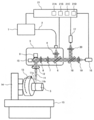
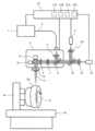
- FIG. 1 is a schematic diagram of a laser welding apparatus in Example 1.
- FIG. It is the schematic diagram of the image which looked at the welding part (molten pool) in Example 1 from the laser irradiation direction.
- 2 is a schematic diagram of an image of a molten pool viewed through a galvano scanner in Example 1.
- FIG. It is a figure which shows the image of a molten pool, luminance distribution, and the image processing method in Example 1.
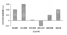
- FIG. It is a figure which shows the improvement effect of the interaction in Example 1.
- FIG. It is a figure which shows the relationship between the number of interaction in Example 1, and a prediction error.
- It is a figure which shows the predicted value and measured value of the penetration depth in Example 1.
- FIG. It is a figure which shows the welding quality determination result in Example 1.
- FIG. 3 is a flowchart of feedback control in the first embodiment. It is a figure which shows the example of a transition of the penetration depth at the time of the feedback control in Example 1.
- FIG. 6 is a flowchart of feedback control in the second embodiment.
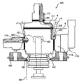
- FIG. 5 is a schematic diagram of a laser welding apparatus in Example 3. It is sectional drawing which shows one Example of the fuel pump which concerns on this invention. It is sectional drawing which shows one Example of the fuel injection valve which concerns on this invention.
- FIG. 1 is a schematic diagram of a laser welding apparatus according to the first embodiment.
- SYMBOLS 1 is a laser oscillator
- 2 is a laser optical fiber
- 3 is a galvano scanner (processing head)
- 4 is a collimator lens which expands a beam width within a galvano scanner
- 5 is a welding object
- 6 is emitted from a welding object 5
- a partial wavelength transmission mirror for sending the reflected light to the camera 16 and the welding light sensor 17
- 7 a Z-axis control lens for controlling the Z-axis position of the laser 11
- 10 is an X-axis control galvanometer mirror that controls the X-axis position of the laser 11
- 10 is a Y-axis control galvanometer mirror that controls the Y-axis position of the laser
- 12 is the direction of rotation of the laser
- 13 is an object to be welded.
- 5 is a rotating spindle
- 14 is a rotary spindle
- 15 is a processing stage
- 18 is a semi-transparent mirror that splits the light emitted from the welding object 5 into the camera 16 and the welding light sensor 17, 9 objective lens for camera
- 20 is an objective lens for welding optical sensor 17, 21 denotes a control device.
- the control device processes the image obtained by the camera 16, predicts the penetration depth in combination with information from the welding light sensor 17, and controls the laser oscillator 1 and the galvano scanner 3 based on the predicted penetration depth. Do.
- the welding object 5 is a fuel pump part, and the material is 304 stainless steel.
- the laser 11 was a disk laser having a wavelength of about 1030 nm.
- the scanning trajectory of the laser 11 was a circle. In FIG. 1, in order to show that the scanning trajectory of the laser 11 is a circle, two laser beams 11 a and 11 b swayed in a direction perpendicular to the welding progress direction (the direction opposite to the rotation direction of the welding object 5). Indicates the state.
- the laser 11 generated by the laser oscillator 1 is sent to the galvano scanner 3 through the optical fiber 2 for laser.
- the laser 11 has its beam width expanded by the collimator lens 4, reflected by the partial wavelength transmission mirror 6, controlled in the Z-axis position by the Z-axis control lens 7, and condensed by the objective lens 8, while being focused by the X-axis galvanometer mirror 9.
- the X- and Y-axis positions are controlled by the Y-axis galvanometer mirror 10, and the welding object 5 is irradiated.
- the welding object 5 is fixed to the rotary spindle 14 and rotated at a predetermined speed.
- the light emitted from the molten pool of the welding object 5 passes through the Y-axis galvano mirror 10, the X-axis galvano mirror 9, the objective lens 8, the Z-axis control lens 7, and the semi-transmissive mirror 18, and further to the camera objective lens 19. To enter the camera 16. Similarly, the light reflected by the semi-transmissive mirror passes through the welding light sensor objective lens 20 and enters the welding light sensor 17.
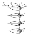
- FIG. 2 is a schematic diagram of an image of the welded portion (molten pool) in Example 1 viewed from the laser irradiation direction.
- FIG. 2 shows the state (image) of the molten pool moving in the welding progress direction.
- 27 indicates the welding progress direction.
- 22 is a molten pool
- 23 is a laser irradiation point
- 24 is a movement locus of the laser irradiation point 23 in the molten pool
- 25 is an X of an image that coincides with the welding traveling direction 27 on a plane (image) perpendicular to the laser irradiation direction.
- An axis 26 indicates a Y axis of an image that coincides with a direction perpendicular to the welding progress direction 27 on a plane (image) perpendicular to the laser irradiation direction. In the image shown in FIG.
- the laser irradiation point has a circular orbit around the origin position of the X and Y axes, and the molten pool 22 Is also at the same position in the XY coordinates.
- a stable penetration depth can be obtained by irradiating the work piece while rotating a laser (high energy beam).
- the image captured by the camera 16 through the galvano scanner 3 shown in FIG. 1 is an image with the laser irradiation point as the origin.
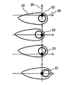
- FIG. 3 is a schematic diagram of an image of a molten pool viewed through a galvano scanner in Example 1. That is, FIG. 3 shows an image of the molten pool with the laser irradiation point as the origin.
- the 23 is the laser irradiation point
- 28 is the X axis of the image with the laser irradiation point as the origin
- 29 is the Y axis of the image with the laser irradiation point as the origin.
- the X axis is parallel to the welding progress direction 27 on a plane (image) perpendicular to the laser irradiation direction.
- the Y axis is perpendicular to the welding progress direction 27 on a plane (image) perpendicular to the laser irradiation direction.
- FIG. 4 is a diagram illustrating an image of a molten pool, a luminance distribution, and an image processing method according to the first embodiment.
- FIG. 4 also shows a method for detecting the molten pool shape by image processing with only a change in luminance.
- 30 is a sputter
- 31 is a horizontal line on the image for measuring luminance
- 32 is a luminance distribution on the horizontal line
- 33 is a distribution (projected value) of a sum of values on the Y-axis 29 (added value)
- 34 Is a threshold line for detecting the start point and end point of the molten pool 22 as projected values
- 35 is the start point and end point of the molten pool obtained based on this threshold value in the X-axis direction and the start point in the Y-axis direction.
- a circumscribed rectangle of the molten pool 22 drawn based on the end point.
- the horizontal line 31 is parallel to the X axis 28 and the welding progress direction 27.
- the outline of the molten pool 22 is always at the same XY coordinates, it is possible to set a region where the molten pool 22 exists, determine that the area outside the molten pool 22 is the sputter 30, and eliminate the spatter 30. .
- the XY coordinates of the outline of the molten pool 22 change, and this method cannot be employed.
- a method is conceivable in which a threshold value is set for the luminance distribution 32 on the horizontal line 31 to obtain the start point and end point of the molten pool 22.
- the sputter 30 cannot be separated because the molten pool 22 and the sputter 30 have the same luminance level.
- a distribution 33 of values obtained by summing the luminance on the Y axis 29 is obtained. Since the sputter 30 has a small width, the value becomes small. However, since the weld pool 22 has a large width, the value becomes large. Therefore, by setting the threshold value 34, the start point and the end point of the molten pool 22 can be obtained without the influence of the sputter 30. In this way, the position of the quadrangle 35 circumscribing the molten pool 22 in the X-axis 28 direction is obtained.
- a distribution 38 of values obtained by summing the luminance on the X axis 28 is obtained, and the threshold value 39 is set to set the direction of the quadrangle 35 circumscribing the molten pool 22 in the Y axis 29 direction. Find the position of.
- the length of the quadrangle 35 circumscribing the obtained molten pool 22 in the X-axis 28 direction is the length of the molten pool 22, and the length in the Y-axis 29 direction is the width of the molten pool 22.
- the area is obtained by binarizing the image in the quadrangle 35 and whitening the binarized area.
- the molten pool shape by performing image processing only on the change in luminance without specifying the position on the image. Accordingly, the shape of the molten pool 22 can be detected even in an image viewed through the galvano scanner 3 shown in FIG. Further, by using the projection value, it is possible to detect the molten pool shape (the molten pool shape information and the molten pool shape data) from which the sputter 30 is separated.
- the length of the molten pool, the width of the molten pool, the length / width of the molten pool, and the area of the molten pool can be obtained.
- the welding light sensor 17 can detect information (welding light sensor information) such as plasma light, temperature (thermal radiation light), and reflected light.
- Y objective variables X1, X2, ...: explanatory variables b1, b2, ...: partial regression coefficient C: constant term.
- the objective variable Y is the penetration depth
- the explanatory variables X1, X2,... Are the shape of the molten pool 22 such as the length of the molten pool and the information of the welding light sensor 17.
- the prediction accuracy of the penetration depth in that case was a maximum error of 0.34 mm.
- temperature thermal radiation light
- reflected light and the like are added as signals of the welding light sensor 17, and the maximum error is improved to 0.23 mm.
- the maximum error was improved to 0.13 mm by adding an interaction that is the multiplication of two items as an explanatory variable.
- the control device 21 constitutes a molten pool shape information detection unit that detects shape information of the molten pool 22 by performing image processing on the image of the molten pool captured by the camera 16.
- the control apparatus 21 comprises the predicted value calculation part 21A which performs the multiple regression analysis and calculates
- the control apparatus 21 has the predicted value calculation part 21A which performs the multiple regression analysis and calculates
- the welding quality judgment system is improved, and the yield is improved.
- FIG. 5 is a diagram showing the improvement effect of the interaction in Example 1.
- the interaction effect varies depending on the combination of the two items to be multiplied.
- FIG. 5 the improvement effect in each interaction of width x area, length x area, reflection (reflected light) x area, temperature x reflection, temperature x area, and temperature x width is shown.
- the length x area has the greatest improvement effect, and the temperature x reflection has a negative improvement effect and is deteriorated.
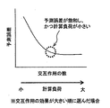
- FIG. 6 is a diagram illustrating the relationship between the number of interactions and the prediction error in the first embodiment.
- the prediction error decreases as the number of interactions increases, but the change is not linear and decreases suddenly, but the slope gradually decreases. Be gentle.
- the computational load increases as the number of interactions increases. Therefore, as indicated by a broken-line circle, there is a point where the prediction error is saturated and the calculation load is small. This is a highly practical point where the calculation load is not so large and the prediction error is small.
- a variable having a small prediction error and a small calculation load is selected and used.
- the prediction error can be reduced and the calculation load can be reduced.
- welding quality can be raised by high-speed feedback of a controlled variable.
- FIG. 7 is a diagram showing a predicted value and an actually measured value of the penetration depth in Example 1.
- FIG. 5 shows various laser outputs when width ⁇ area is used, measured values of penetration depth at the defocus distance, and values predicted by the above method. For 20 cases (number of welds) 1 to 20, the penetration depth was measured and predicted. As a result, in this embodiment, the penetration depth can be predicted with high accuracy with a maximum error of 0.13 mm.
- 36 is a threshold value for determining the welding quality with respect to the actual measurement value, and is set to 0.8 mm for the actual welding site.
- the welding quality is determined using this threshold value. If it is equal to or greater than the threshold value, it is determined as a non-defective product (OK product), and if it is less than the threshold value, it is determined as a defective product (NG product).
- This determination is executed by the control device 21. That is, the control device 21 constitutes a quality determination unit 21B that performs welding quality determination. Or the control apparatus 21 has the quality determination part 21B which performs welding quality determination.
- the control device 21 has a partial regression analysis coefficient storage unit 21C that stores the partial regression analysis coefficients described above.
- FIG. 8 is a view showing the welding quality determination result in Example 1.
- Measured values are 18 cases for OK products with a threshold of 0.8 mm or more and 2 cases for NG products less than 0.8 mm.
- the predicted value considering the error of 0.13 mm there are 18 cases of OK products with a threshold value of 0.93 mm or more and 2 cases of NG products having a threshold less than 0.93 mm.
- both the false alarm for determining a non-defective product as a defective product and the bad report for determining a defective product as a non-defective product are 0 cases, and the false alarm rate is 0%.
- FIG. 9 is a diagram illustrating a feedback control section in the first embodiment.
- the laser output consists of a slope-up section 91 that increases from approximately 0 to the laser output of the main welding, a main welding section 92, a lap portion 93 that overlaps after one round, and a slope-down section 94 that decreases to approximately zero.
- the change in signal intensity is not very stable, so feedback control is not performed.
- the main welding section 92 and the lap portion 93 where the laser output is constant are set as a feedback control section 90.
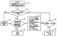
- FIG. 10 is a flowchart of feedback control in the first embodiment.
- step 52 it is determined whether or not the predicted penetration depth is within the upper and lower limits. If YES, the welding condition is maintained in step 53, and it is determined in step 54 whether the welding time has exceeded the feedback control section end time. If NO, return to step 52. If NO in step 52, it is determined in step 55 whether the predicted value is greater than or equal to a threshold value. If NO, an NG alarm is issued at step 56 and the product is determined to be defective. If YES in step 55, feedback control is performed. The laser output is adjusted by PID control (proportional integral derivative control), and the corrected output value is obtained by the following equation.
- PID control proportional integral derivative control
- Corrected output value previous output value + Kp x deviation + Ki x cumulative value of deviation + Kd x difference between current deviation and previous deviation, where Kp: proportional control coefficient, Ki: integral control coefficient, Kd: differential control coefficient.
- the penetration depth is converted into the laser output value by the relational expression between the laser output value and the penetration depth obtained in advance.
- the laser output is increased, and when the predicted value is larger than the target value, the laser output is decreased.
- step 54 it is determined whether the welding time has exceeded the end time Te90 of the feedback control section 90. If NO, return to step 52. If the determination in step 54 is YES, the feedback control is terminated in step 58 and it is determined that the product is non-defective.
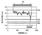
- FIG. 11 is a diagram illustrating a transition example of the penetration depth during feedback control in the first embodiment.
- FIG. 11 shows a specific example of feedback control.
- SH0 is a threshold value for determining whether the welded product is OK or NG, and corresponds to the above-mentioned 0.8 mm.
- the threshold value of the predicted value in step 55 is set to a threshold value SH1 having a value larger than SH0. In this case, it is desirable that the threshold value SH1 of the predicted value is 0.93 mm or more in consideration of the above-described error 0.13 mm.
- the lower limit value (lower limit value) SH2 for starting feedback control is set to a value larger than the threshold value SH1.
- the difference between the threshold value SH1 and the lower limit value SH2 may be determined in consideration of the time delay until the effect of feedback control appears after the predicted value of the penetration depth falls below the lower limit.
- Threshold value SH0, lower limit value SH2, and upper limit value SH3 are all set within the allowable range of the penetration depth. Further, a threshold value for determining whether the welded product is an OK product or an NG product may be provided in a numerical range larger than the upper limit value (upper limit value) SH3.
- the feedback control section 90 it is determined whether the predicted penetration depth is within the upper and lower limits, and if it is within the upper and lower limits, the welding conditions are maintained.
- the penetration depth prediction value falls below the lower limit, feedback control is started. In this case, since the penetration depth prediction value is smaller than the target value, the penetration depth is increased by increasing the laser output. When the penetration depth prediction value is larger than the target value, the penetration depth is decreased by decreasing the laser output.
- the present invention is applied to butt welding, but the weld joint structure is not limited to this.
- the type of laser used, the material of the welding object, and the laser welding conditions are not limited to this.
- the penetration depth is an important factor that greatly affects the welding quality. In butt welding, the welding quality can be improved and the yield can be improved.
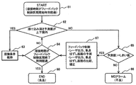
- FIG. 12 is a flowchart of feedback control in the second embodiment.
- symbol as Example 1 is attached
- FIG. 12 is a flowchart of feedback control in the second embodiment.
- symbol as Example 1 is attached
- FIG. 12 is a flowchart of feedback control in the second embodiment.
- symbol as Example 1 is attached
- the second embodiment can be performed using the same laser welding apparatus as the first embodiment. Moreover, the predicted value of the penetration depth is obtained by the method described in the first embodiment. In other words, the feedback control flow has a configuration different from that of the first embodiment.
- step 61 when the welding time exceeds the start time Ts90 of the feedback control section 90, the feedback control flowchart is started.
- step 62 it is determined whether the predicted value of the penetration depth is within the upper and lower limits (SH3, SH2). If YES, the welding condition is maintained in step 63, and it is determined in step 64 whether the welding time has exceeded the end time Te90 of the feedback control section 90. If no, continue to step 62. If NO in step 62, it is determined in step 65 whether the predicted value is greater than or equal to the threshold value SH1. In the case of NO, an NG alarm is issued at step 66 and it is determined that the product is defective. If YES in step 65, feedback control is performed.
- SH3 upper and lower limits
- the laser output and the defocus distance are predicted by multiple regression analysis based on the experimental results.
- the predicted laser output and defocus distance are compared with the target laser output and defocus distance, and if they are different, PID control (proportional integral derivative control) is performed so that the target value is obtained.
- PID control proportional integral derivative control
- step 64 it is determined whether or not the welding time has exceeded the end time Te90 of the feedback control section 90. If NO, the process returns to step 62 to continue the process. If YES in step 64, the process ends in step 68, and the product is determined to be non-defective.
- Example 1 in step 57, the predicted value of the penetration depth was compared with the target value, and feedback control was performed.
- the laser output and the defocus distance are predicted, and these predicted values are compared with the target value to perform feedback control. The same effect as that of the first embodiment can be obtained by such feedback control.
- the steps 61 to 66 and 68 of the second embodiment can be performed in the same manner as the steps 51 to 56 and 58 of the first embodiment.
- the output of the laser 11 is changed by feedback control.
- the laser output and the defocusing distance are changed by feedback control.
- the moving speed of the laser beam 11 with respect to the welding object (workpiece) 5, 5A is changed.
- Laser irradiation conditions may be changed.
- the moving speed of the laser beam 11 with respect to the workpieces 5 and 5A can be changed by changing the rotation speed of the welding objects 5 and 5A.
- the moving speed of the laser beam 11 with respect to the workpieces 5 and 5A can be changed by changing the scanning speed of the laser 11 forming a circle.
- the moving speed of the laser beam 11 relative to the workpieces 5 and 5A can be changed by changing both the rotation speed of the welding objects 5 and 5A and the scanning speed of the laser 11.
- the laser output conditions high-energy beam irradiation conditions
- the laser irradiation condition or the correction amount is calculated by the control device 21. That is, the control device 21 configures a feedback control unit 21D that outputs the correction amount and controls the high energy beam irradiation device.
- the control device 21 includes a feedback control unit 21D that outputs the correction amount and controls the high energy beam irradiation device.
- the feedback control unit may preferentially control the laser output value (output value of the high energy beam) among the laser irradiation conditions.
- the laser output value that is, the laser intensity, can be controlled easily and at high speed among other laser irradiation conditions. Feedback control can be performed easily and at high speed.
- FIG. 13 is a schematic diagram of a laser welding apparatus according to the third embodiment.
- the welding object 5A is different from the first embodiment. About others, it is the same as Example 1.
- the welding object 5A was a fuel injection part.
- the welding joint of the welding object 5A has a lap welding structure.
- Example 3 the welding is applied to lap welding, but the weld joint structure is not limited to this.
- the type of laser used, the material of the welding object, and the laser welding conditions are not limited to this.
- the feedback control described in the second embodiment may be applied to the third embodiment.
- the fourth embodiment is an example in which the welding method according to the present invention is applied to a high-pressure fuel supply pump.
- FIG. 14 is a cross-sectional view showing an embodiment of a fuel pump according to the present invention.
- the high-pressure fuel supply pump 100 is a pump that supplies the fuel pumped up from the fuel tank by a feed pump (not shown) to the fuel injection valve at a high pressure.
- the high-pressure fuel supply pump 100 is used for an internal combustion engine (engine) on which a vehicle is mounted.
- the high-pressure fuel supply pump 100 will be referred to as a pump 100 and will be described.
- a pressurizing chamber 107 is formed in the dredge pump body 101, and an upper end portion (tip portion) of the plunger 104 is inserted into the pressurizing chamber 107.
- the plunger 104 reciprocates in the pressurizing chamber 107 to pressurize the fuel.
- the pump body (pump housing) 101 has a mounting flange 102 for fixing to the engine.
- the mounting flange 102 is welded to the pump body 101 by laser welding on the entire circumference.
- a welded portion 301 between the mounting flange 102 and the pump main body 101 is referred to as a first welded portion.
- the pump body 101 is provided with a suction valve mechanism 114 and a discharge valve mechanism 115.
- the body 114c of the suction valve mechanism 114 is fixed to the pump body 101 by laser welding. This weld location 302 is referred to as a second weld. In the second welded portion 302, the outer periphery of the body 114c of the suction valve mechanism 114 is welded over the entire periphery.
- a discharge joint 116 is provided on the downstream side of the discharge valve mechanism 115.
- the discharge joint 116 is fixed to the pump body 101 by laser welding.
- This weld location 303 is referred to as a third weld.
- the outer periphery of the discharge joint 116 is welded over the entire circumference.
- a damper cover 111 is attached to the top of the pump body 101.
- the damper cover 111 is fixed to the pump body 101 by laser welding.
- This weld location 304 is referred to as a fourth weld.
- the fourth welded portion 304 is welded over the entire circumference.
- the suction joint 112 is fixed to the damper cover 111 by laser welding.
- This weld location 305 is referred to as a fifth weld.
- the outer periphery of the suction joint 112 is welded over the perimeter.
- the weld joints of the first weld 301, the second weld 302, and the third weld 303 have a butt weld structure, and the first weld 301, the second weld 302, and the third weld 303 are welds of the first embodiment. Welded in the process.
- the laser 11 is irradiated to the welding object surface perpendicularly.
- the laser 11 is irradiated with an inclination of ⁇ ° from the direction perpendicular to the surface of the welding object.
- the weld joints of the fourth welded portion 304 and the fifth welded portion 305 have a lap weld structure, and the fourth welded 304 and the fifth welded portion 305 are welded by the welding process of the third embodiment.
- the laser 11 is irradiated perpendicularly to the surface of the welding object.
- the fuel leakage is not allowed in the pump 100.
- the pump body 101, the body 114c of the suction valve mechanism 114, the discharge joint 116, the damper cover 111, and the suction joint 112 are components that constitute a fuel passage through which fuel flows.
- the second weld 302 to the fifth weld 305 also serve as a fuel seal. For this reason, it is desirable to ensure a sufficient penetration depth for welding the parts where the fuel flow path is formed.
- the pump 100 is assumed to be used in a severe environment. By using a welding process having excellent robustness, the reliability of the pump 100 can be increased.
- FIG. 15 shows a fifth embodiment in which the present invention is applied to the fuel injection valve 200.
- FIG. 15 is a sectional view showing an embodiment of the fuel injection valve according to the present invention.
- the fuel injection valve 200 is provided with a cylindrical body 201 made of a metal material extending from the upper end to the lower end.
- a valve seat member 204 is provided at the tip of the cylindrical body 201.
- the valve seat member 204 is formed with a conical surface, and the valve seat 204b is formed on the conical surface.
- the valve seat member 204 is inserted into the inner end of the cylindrical body 201 and is fixed to the cylindrical body 201 by laser welding.
- This welded portion 306 is referred to as a sixth welded portion 306.
- the sixth welded portion 306 is welded over the entire periphery from the outer peripheral side of the cylindrical body 201.
- a nozzle plate 206 is attached to the lower end surface (tip surface) of the valve seat member 204.
- the nozzle plate 206 is provided with a plurality of fuel injection holes 207.
- the nozzle plate 206 is fixed to the valve seat member 204 by laser welding.
- This welded portion 307 is referred to as a seventh welded portion 307.
- the seventh welded portion 307 is formed so as to surround the circumference of the injection hole forming region where the fuel injection hole 207 is formed.
- the movable body 208 is accommodated in the cylindrical body 201.
- a valve body 205 is fixed to the tip of the mover 208.
- the valve body 205 is constituted by a ball valve having a spherical shape.
- the valve body 205 is fixed to the mover 208 by laser welding.
- This weld location 308 is referred to as an eighth weld 308.
- the eighth welded portion 308 is welded over the entire outer periphery of the distal end portion of the mover 208.
- the valve body 205 and the valve seat 204b cooperate to open and close the fuel passage.
- the fuel passage is closed when the valve body 205 contacts the valve seat 204b. Further, the fuel passage is opened when the valve body 205 is separated from the valve seat 204b.
- the fuel that has passed through the fuel passage between the valve body 205 and the valve seat 204b is injected from the fuel injection hole 207.
- the weld joints of the sixth weld 306 and the seventh weld 307 have a lap weld structure, and the sixth weld 306 and the seventh weld 307 are welded by the welding process of the third embodiment.
- the surface of the welding object is irradiated with the laser 11 perpendicularly.
- the laser 11 may be irradiated while being inclined from a direction perpendicular to the surface of the welding object.
- the welding joint of the eighth welded portion 308 has a butt structure, and the eighth welded portion 308 is welded by the welding process of Example 1.
- the laser 11 is irradiated perpendicularly to the surface of the welding object.
- the laser 11 may be irradiated while being inclined from a direction perpendicular to the surface of the welding object.
- the fuel injection valve 200 does not allow fuel leakage.
- the cylindrical body 201, the valve seat member 204, and the nozzle plate 206 are members that constitute a fuel passage through which fuel flows.
- the sixth welded portion 306 and the seventh welded portion 307 also serve as a fuel seal. For this reason, it is desirable to ensure a sufficient penetration depth. Further, the fuel injection valve 200 is assumed to be used in a severe environment. By using a welding process with excellent robustness, the reliability of the fuel injection valve 200 can be increased.
- valve body 205 repeatedly collides with the valve seat 204b over a long period of time. For this reason, the welding of the valve body 205 and the mover 208 in the eighth welded portion 308 needs to be reliable so that the welded portion can be kept stable over a long period of time. By applying the welding process according to the present invention, the reliability of the welded portion is ensured.
- this invention is not limited to each above-mentioned Example, Various modifications are included.
- the above-described embodiments have been described in detail for easy understanding of the present invention, and are not necessarily limited to those having all the configurations.
- a part of the configuration of one embodiment can be replaced with the configuration of another embodiment, and the configuration of another embodiment can be added to the configuration of one embodiment.
- Patent Document 1 Japanese Patent Publication No. 2006-43741
- Patent Document 2 JP-A-2005-14027
- Laser irradiation point, 24 The movement locus of the laser irradiation point in the molten pool, 25 ... X axis of the image viewed from the viewpoint of moving in the welding progress direction, 26 ... Y-axis of the image viewed from the viewpoint of moving in the welding progress direction, 27 ... Welding direction, 28 ... X-axis of the image with the laser irradiation point as the origin, 29 ... Y-axis of the image with the laser irradiation point as the origin, 30: Spatter, 31 ... a horizontal line on the image whose luminance is to be measured, 32 ... Luminance distribution on the horizontal line 31 33 ...
Landscapes
- Engineering & Computer Science (AREA)
- Physics & Mathematics (AREA)
- Optics & Photonics (AREA)
- Mechanical Engineering (AREA)
- Plasma & Fusion (AREA)
- Quality & Reliability (AREA)
- Laser Beam Processing (AREA)
- Fuel-Injection Apparatus (AREA)
Abstract
高エネルギービーム溶接において、溶接品質の判定精度、あるいはフィードバックにより一定の溶接品質に保つ精度を向上することができ、溶接品の製造効率、すなわち歩留まりを向上する。 カメラで溶融池の画像を取得し、画像処理により溶融池の幅と長さ、面積を取得し、さらに、光センサで反射光、プラズマ、熱放射光を取得し、上記信号とその中の交互作用を持つ信号を活用して重回帰分析を行うことにより溶け込み深さを高精度に予測し、溶接品質を高精度に判定するとともに、ビーム出力、焦点位置の予測も行い、ビーム出力、焦点位置のフィードバック制御を行って、ビーム出力、焦点位置を適正な値に維持することにより、溶接品質を一定に保つことを特徴とする。
Description
本発明は高エネルギービーム溶接に関し、特に自動車部品の高エネルギービーム溶接方法に関するものである。
高エネルギービーム溶接は、溶け込みが深い溶接が可能であり、従来のアーク溶接と比較して、精密にかつ高速に溶接が可能であるため、近年、利用が拡大している。溶け込みが深い溶接ができる理由として、高エネルギービームがアーク溶接などと比べて、高いパワー密度を有していることが挙げられる。高いパワー密度を有する高エネルギービームが照射された金属は瞬時に、溶融、蒸発する。その蒸発による高い反力によって、溶融部は押し下げられ、キーホールと呼ばれる空間が形成される。高エネルギービームはキーホールを通じて、材料内部まで到達できるため、溶け込みが深い溶接が達成される。高エネルギービーム溶接においては、従来、製品全数の溶接条件の管理、あるいは抜き取り検査での溶接品質の評価にとどまり、製品全数において実際の溶接状態を監視することは困難であった。そのため、現状では、レンズの定期的清掃、溶接条件の定期的確認により、溶接品質を向上する対策が行われていた。しかし、高エネルギービーム溶接の信頼性を向上する根本対策としては、実際の溶接状態を監視することによって製品全数の品質を保証すること、または不良になりそうな場合に溶接条件にフィードバック制御することにより不良の発生を抑制することが望まれていた。
このような課題に対する対策として、特開2006-43741号公報(特許文献1)に記載されているように、カメラで溶融部を撮像し、撮像した画像に画像処理を行うことにより不良を判定する方法が提案されている。或いはその他の方法として、特開2005-14027(特許文献2)に記載されているように、イメージセンサの画像を処理、解析して溶接加工機の出力と送り速度にフィードバックする方法が提案されている。
特許文献1に記載の方法は、溶融池近傍の撮像を行い、画像処理により溶融池の幅と長さを演算し、その値が予め記憶したしきい値よりも大きい場合に不良と判定している。また、特許文献2に記載の方法は、画像処理により溶融池の大きさや形状を認識し、これを直ちに解析して溶接加工機の出力と送り速度にフィードバックしている。これらの手法をレーザ溶接に適用することで溶接不良を判定、および溶接品質を均一化することにより溶接欠陥を防止することが可能と推定される。しかしながら上記手法では、例えば突合せ継手において最も重要な溶け込み深さを高精度に予測することについて十分な配慮が成されていないため、品質判定の精度、あるいはフィードバックにより一定の品質に保つ精度を向上することに課題があった。この課題は、製造効率の向上、すなわち歩留まりの向上を阻害する要因となっている。
本発明の目的は、高エネルギービーム溶接において、溶接品質の判定精度、あるいはフィードバックにより一定の溶接品質に保つ精度を向上することができ、溶接品の製造効率、すなわち歩留まりを向上することにある。
上記目的を達成するために、本発明の高エネルギービーム溶接の品質判定方法は、
被溶接物に高エネルギービームを照射して溶接を行う高エネルギービーム溶接の品質判定方法であって、
カメラで撮像した溶融池の画像を画像処理することにより検出した溶融池の形状情報と、
溶接光センサで検出したプラズマ光を含む溶接光センサ情報と、
溶融池の溶け込み深さを目的変数とし前記形状情報及び前記溶接光センサ情報を説明変数とする重回帰分析を行うことにより求められる偏回帰分析係数と、
に基づいて、溶融池の溶け込み深さの予測値を求め、
前記予測値を基準値と比較することにより溶接の品質を判定する。
被溶接物に高エネルギービームを照射して溶接を行う高エネルギービーム溶接の品質判定方法であって、
カメラで撮像した溶融池の画像を画像処理することにより検出した溶融池の形状情報と、
溶接光センサで検出したプラズマ光を含む溶接光センサ情報と、
溶融池の溶け込み深さを目的変数とし前記形状情報及び前記溶接光センサ情報を説明変数とする重回帰分析を行うことにより求められる偏回帰分析係数と、
に基づいて、溶融池の溶け込み深さの予測値を求め、
前記予測値を基準値と比較することにより溶接の品質を判定する。
また上記目的を達成するために、本発明の高エネルギービーム溶接の品質判定装置は、
被溶接物に高エネルギービームを照射して溶接を行う高エネルギービーム溶接の品質判定装置であって、
カメラで撮像した溶融池の画像を画像処理することにより溶融池の形状情報を検出する溶融池形状情報検出部と、
プラズマ光を含む溶接光センサ情報を検出する溶接光センサと、
溶融池の溶け込み深さを目的変数とし前記形状情報及び前記溶接光センサ情報を説明変数とする重回帰分析を行うことにより求められる偏回帰分析係数を記憶する偏回帰分析係数記憶部と、
前記溶融池形状情報、前記溶接光センサ情報及び前記偏回帰分析係数に基づいて、溶融池の溶け込み深さの予測値を求める予測値算出部と、 前記予測値を基準値と比較することにより溶接の品質を判定する品質判定部と、を備える。
また上記目的を達成するために、本発明の高エネルギービーム溶接の溶接管理システムは、 高エネルギービーム溶接の溶接管理システムであって、 被溶接物に高エネルギービームを照射して溶接を行う高エネルギービーム照射装置と、
溶融池の画像を撮像するカメラと、
前記カメラで撮像した溶融池の画像を画像処理することにより溶融池の形状情報を検出する溶融池形状情報検出部と、
プラズマ光を含む溶接光センサ情報を検出する溶接光センサと、
溶融池の溶け込み深さを目的変数とし前記形状情報及び前記溶接光センサ情報を説明変数とする重回帰分析を行うことにより求められる偏回帰分析係数を記憶する偏回帰分析係数記憶部と、
前記溶融池形状情報、前記溶接光センサ情報及び前記偏回帰分析係数に基づいて、溶融池の溶け込み深さの予測値を求める予測値算出部と、
前記予測値を基準値と比較することにより溶接の品質を判定する品質判定部と、
前記予測値と前記基準値との比較結果に基づいて高エネルギービームの照射条件を修正する修正値を出力し、前記高エネルギービーム照射装置が出力する高エネルギービームをフィードバック制御するフィードバック制御部と、
を備える。
本発明によれば、溶接品質の判定精度、あるいはフィードバックにより一定の溶接品質に保つ精度を向上することができ、溶接品の製造効率、すなわち歩留まりを向上することができる。
以下、本発明に係る実施例について、図面を用いて説明する。
図1は、実施例1におけるレーザ溶接装置の模式図である。
11はレーザ、16はカメラ、17は溶接光センサを示す。1はレーザ発振器、2はレーザ用の光ファイバ、3はガルバノスキャナ(加工ヘッド)、4はガルバノスキャナ内でビーム幅を広げるコリメータレンズ、5は溶接対象物、6は溶接対象物5から発せられた光をカメラ16や溶接光センサ17に送る一部波長透過ミラー、7はレーザ11のZ軸位置を制御するZ軸制御レンズ、8は広いビーム幅のレーザ11を溶接対象物5に集光させる対物レンズ、9はレーザ11のX軸位置を制御するX軸制御ガルバノミラー、10はレーザ11のY軸位置を制御するY軸制御ガルバノミラー、12はレーザの回転方向、13は溶接対象物5の回転方向、14はロータリースピンドル、15は加工ステージ、18は溶接対象物5から発せられた光をカメラ16と溶接光センサ17に分光する半透過ミラー、19はカメラ16用の対物レンズ、20は溶接光センサ17用の対物レンズ、21は制御装置を示している。なお制御装置は、カメラ16で得た画像を処理し、溶接光センサ17からの情報と合わせて溶け込み深さを予測し、予測した溶け込み深さに基づいてレーザ発振器1、ガルバノスキャナ3の制御を行う。
本実施例では、溶接対象物5は燃料ポンプ部品とし、素材は304ステンレス鋼とした。またレーザ11は波長が約1030nmのディスクレーザとした。レーザ11の走査軌道は円とした。図1では、レーザ11の走査軌道が円であることを示すため、溶接進行方向(溶接対象物5の回転方向とは反対方向)に垂直な方向に振られた2つのレーザビーム11a,11bの状態を示している。
レーザ発振器1で生成されたレーザ11はレーザ用の光ファイバ2を通じて、ガルバノスキャナ3に送られる。レーザ11はコリメータレンズ4でビーム幅が広げられ、一部波長透過ミラー6で反射され、Z軸制御レンズ7でZ軸位置を制御され、対物レンズ8で集光されつつ、X軸ガルバノミラー9、Y軸ガルバノミラー10でX、Y軸位置を制御されて、溶接対象物5に照射される。溶接対象物5はロータリースピンドル14に固定され、所定の速度で回転させる。溶接対象物5の溶融池から発せられた光は、Y軸ガルバノミラー10、X軸ガルバノミラー9、対物レンズ8、Z軸制御レンズ7、半透過ミラー18を通過し、さらにカメラ用対物レンズ19を通過してカメラ16に入る。同様に半透過ミラーで反射された光は溶接光センサ用対物レンズ20を通過して溶接光センサ17に入る。
本実施例では、溶接継ぎ手構造の一例として、突合せ継ぎ手の場合について説明する。
図2は、実施例1における溶接部(溶融池)をレーザ照射方向から見た画像の模式図である。図2では、溶接進行方向に移動する溶融池の状態(画像)が示されている。
27は溶接進行方向を示している。22は溶融池、23はレーザ照射点、24はレーザ照射点23の溶融池22内における移動軌跡、25はレーザ照射方向に垂直な平面(画像)上で溶接進行方向27に一致する画像のX軸、26はレーザ照射方向に垂直な平面(画像)上で溶接進行方向27に垂直な方向に一致する画像のY軸を示している。図2に示す画像(以下、「溶接進行方向27に移動する視点から見た画像」という)では、X,Y軸の原点位置を中心にレーザ照射点が円軌道を描いており、溶融池22の輪郭もXY座標の同じ位置にある。
なお、本実施例では、レーザ(高エネルギービーム)を回転させながら被溶接物に照射することにより、安定した溶け込み深さを得ることができる。
これに対し、図1に示すガルバノスキャナ3を通してカメラ16で撮像される画像は、レーザ照射点を原点とした画像になる。
図3は、実施例1におけるガルバノスキャナを通して見た溶融池の画像の模式図である。すなわち図3では、レーザ照射点を原点とした溶融池の画像を示す。
23はレーザ照射点、28はレーザ照射点を原点とした画像のX軸、29はレーザ照射点を原点とした画像のY軸である。X軸は、レーザ照射方向に垂直な平面(画像)上で溶接進行方向27に平行である。Y軸は、レーザ照射方向に垂直な平面(画像)上で溶接進行方向27に垂直である。
レーザ照射点を原点とした画像では、X,Y軸の原点の周りを溶融池が回転する画像が得られ、溶融池の輪郭は、XY座標の異なる位置にいることがわかる。そのため、ガルバノスキャナ3を通して見た画像では、XY座標を固定した領域で画像処理をするのでは、溶融池22の輪郭を正確に得ることができない。そこで、位置ではなく、輝度の変化のみの画像処理による溶融池形状検出を行う必要がある。
図4は、実施例1における溶融池の画像と輝度分布、画像処理方法を示す図である。図4では、輝度の変化のみの画像処理により溶融池形状検出を行う方法も示す。
30はスパッタ、31は輝度を計測する画像上の水平線、32は水平線31上の輝度分布、33はY軸29上の輝度を合計した値(足し合わせた値)の分布(投影値)、34は投影値で溶融池22の始点、終点を検知するためのしきい値の線、35はこのしきい値を元に得た溶融池のX軸方向の始点及び終点と、Y軸方向の始点及び終点とを元に描画した溶融池22の外接四角形を示している。なお水平線31は、X軸28及び溶接進行方向27に平行である。
カメラ16で得られる画像には、溶融池22だけでなく、溶接の際に発生するスパッタ30も撮像される。この画像を単純に2値化するとスパッタと溶融池の分離ができず、スパッタ30も溶融池22の一部と判断され、溶融池22の長さにスパッタ30も含まれてしまう。そのため、正確な溶融池22の長さを得ることができない。
溶融池22の輪郭が常に同じXY座標にいるのであれば、溶融池22の存在する領域を設定してそれより外にあるものをスパッタ30と判断してスパッタ30を排除することが可能である。しかし、ガルバノスキャナ3を通して見た画像では、溶融池22の輪郭のXY座標が変化するため、この方法は採用できない。
そこで、例えば水平線31上の輝度分布32に対して、しきい値を設定して溶融池22の始点及び終点を求める方法が考えられる。しかし、輝度分布32を見ると分かるように、溶融池22とスパッタ30の輝度レベルが同じぐらいであるため、スパッタ30を分離することができない。
そこで、まず、Y軸29上の輝度を合計した値の分布33を求める。スパッタ30は幅が細いため値が小さくなるが、溶融池22は幅が太いため値が大きくなる。そのため、閾値34を設定することで、スパッタ30の影響を排除して溶融池22の始点及び終点を求めることができる。このようにして、溶融池22に外接する四角形35のX軸28方向の位置を求める。Y軸29上の輝度分布33と同様に、X軸28上の輝度を合計した値の分布38を求め、しきい値39を設定することで溶融池22に外接する四角形35のY軸29方向の位置を求める。
求められた溶融池22に外接する四角形35のX軸28方向の長さを溶融池22の長さ、Y軸29方向の長さを溶融池22の幅とする。面積は、この四角形35内の画像を2値化し、2値化により白となった領域により求める。
このように画像上の位置を特定せずに、輝度の変化のみを画像処理することによって、溶融池形状の検出を行うことができる。これにより、図3に示したガルバノスキャナ3を通して見た画像でも溶融池22の形状を検出することが可能となる。さらに、投影値を使うことにより、スパッタ30を分離した溶融池形状(溶融池の形状情報、溶融池の形状データ)を検出することが可能となる。これにより本実施例では、溶融池の長さ、溶融池の幅、溶融池の長さ/幅、溶融池の面積を得ることができる。
一方、溶接光センサ17では、プラズマ光、温度(熱放射光)及び反射光等の情報(溶接光センサ情報)の検出が可能である。
次に、溶接対象物5に集光させる対物レンズ8の焦点位置から焦点をわざとZ軸方向にはずした距離である焦点はずし距離や、レーザ出力を振って溶接実験を行った際に得られる溶融池22の形状と、溶接光センサ17の情報とを用いて、その時の溶け込み深さのデータの重回帰分析を行い、これらの情報と溶け込み深さの偏回帰分析係数を求める。重回帰分析とは、1つの目的変数を複数の説明変数で予測する分析方法であり、式1で表される。
Y=b1×X1+b2×X2+・・・+C (式1)
ここで、
Y:目的変数
X1、X2、…:説明変数
b1、b2、…:偏回帰係数
C:定数項
である。
本実施例の場合、目的変数Yは溶け込み深さであり、説明変数X1、X2、…は溶融池の長さなどの溶融池22の形状と溶接光センサ17の情報である。
Y=b1×X1+b2×X2+・・・+C (式1)
ここで、
Y:目的変数
X1、X2、…:説明変数
b1、b2、…:偏回帰係数
C:定数項
である。
本実施例の場合、目的変数Yは溶け込み深さであり、説明変数X1、X2、…は溶融池の長さなどの溶融池22の形状と溶接光センサ17の情報である。
従来の方法では、溶接光センサ信号としてプラズマ光のみを使用しているが、その場合の溶け込み深さの予測精度は、最大誤差0.34mmであった。本実施例では、溶接光センサ17の信号として温度(熱放射光)及び反射光等を追加しており、これによって最大誤差は0.23mmまで改善した。また、説明変数として二つの項目の掛け算である交互作用を追加することにより、最大誤差を0.13mmまで改善した。
本実施例では、制御装置21が、カメラ16で撮像した溶融池の画像を画像処理することにより溶融池22の形状情報を検出する溶融池形状情報検出部を構成する。また制御装置21は、重回帰分析を行って溶融池22の溶け込み深さの予測値を求める予測値算出部21Aを構成する。或いは制御装置21は、重回帰分析を行って溶融池22の溶け込み深さの予測値を求める予測値算出部21Aを有する。
このように本実施例では、溶接の品質判定制度が向上し、歩留まりが改善される効果が得られる。
図5は、実施例1における交互作用の改善効果を示す図である。
交互作用は掛け算する2項目の組み合わせにより、改善効果が異なる。図5では、幅×面積、長さ×面積、反射(反射光)×面積、温度×反射、温度×面積及び温度×幅の各交互作用における改善効果を示している。図5の場合、長さ×面積が最も改善効果が大きく、温度×反射は改善効果がマイナスとなり改悪することになる。
図6は、実施例1における交互作用の数と予測誤差の関係を示す図である。
交互作用の効果が大きいものが左側に来るように選んだ場合、交互作用の数が多くなると予測誤差が小さくなるが、その変化は直線的ではなく、初め急に減少するが、徐々に傾きが緩やかになる。一方、交互作用の数が増えると計算負荷が増加する。そのため、破線の丸で示すように、予測誤差が飽和し、かつ計算負荷が小さい点が存在する。この点が、計算負荷はそれほど大きくなく、予測誤差は小さい実用性の高い点となる。
そこで本実施例では、上述した説明変数として予測誤差が小さくなりかつ計算負荷が小さくなるものを選択して利用する。これにより、予測誤差を小さくできると共に、計算負荷を小さくすることができる。そして後述するフィードバック制御に当たっては、制御量の高速なフィードバックにより、溶接品質を高めることができる。
図7は、実施例1における溶け込み深さの予測値と実測値とを示す図である。
図7では、説明変数として、温度、プラズマ、反射光、溶融池の長さ、溶融池の幅、溶融池の長さ/幅、溶融池の面積、温度×プラズマ、温度×幅、プラズマ×幅、幅×面積を使用した場合のさまざまなレーザ出力、焦点はずし距離での溶け込み深さの実測値と上記方法により予測した値とを示している。1~20の20ケース(溶接数)について、溶け込み深さの実測及び予測を行った。その結果、本実施例では、最大誤差0.13mmで高精度に溶け込み深さを予測可能である。
36は実測値に対する溶接品質判定のしきい値で、本溶接部位では0.8mmに設定されている。37は最大誤差0.13mmを考慮した予測値での溶接判定のしきい値で、0.8+0.13=0.93mmである。このしきい値を用いて溶接品質判定を行う。しきい値以上であれば良品(OK品)、しきい値未満であれば不良品(NG品)と判定する。この判定は、制御装置21で実行される。すなわち制御装置21は、溶接品質判定を行う品質判定部21Bを構成する。或いは制御装置21は、溶接品質判定を行う品質判定部21Bを有する。また制御装置21は、上述した偏回帰分析係数を記憶する偏回帰分析係数記憶部21Cを有する。
図8は、実施例1における溶接品質判定結果を示す図である。
実測値では、しきい値0.8mm以上のOK品が18ケース、0.8mm未満のNG品が2ケースである。誤差0.13mmを考慮した予測値では、しきい値0.93mm以上のOK品が18ケース、0.93mm未満のNG品が2ケースである。またこの予測値では、良品を不良品と判定する虚報及び不良品を良品と判定する悪報は、ともに0ケースで、虚報率は0%である。
次に、予測した溶け込み深さが設定した上下限値からはずれようとする場合に、レーザ出力をフィードバック制御することにより、上下限値からはずれないようにする溶接方法について説明する。
図9は、実施例1におけるフィードバック制御区間を示す図である。
レーザ出力は、ほぼ0から本溶接のレーザ出力まで上げるスロープアップ区間91、本溶接区間92、1周回った後オーバーラップさせるラップ部93、ほぼ0まで下げるスロープダウン区間94からなる。この内、スロープアップ区間91とスロープダウン区間94では、信号強度の変化が大きく安定しないため、フィードバック制御は行わない。レーザ出力が一定となる本溶接区間92とラップ部93をフィードバック制御区間90とする。
図10は、実施例1におけるフィードバック制御のフローチャートである。
ステップ51で溶接時間がフィードバック制御区間90の開始時刻Ts90を超過するとフィードバック制御のフローチャートを開始する。ステップ52で溶け込み深さ予測値が上下限内か判定する。YESの場合はステップ53で溶接条件を維持し、ステップ54で溶接時間がフィードバック制御区間終了時刻を超過したかを判定する。NOの場合は、ステップ52に戻り続ける。ステップ52でNOの場合はステップ55で予測値がしきい値以上か判定する。NOの場合は、ステップ56でNGアラームを出し、不良品と判定する。ステップ55でYESの場合は、フィードバック制御を行う。レーザ出力の調整をPID制御(比例積分微分制御)で行うが、修正出力値は、次式により求める。
修正出力値=前回の出力値+Kp×偏差+Ki×偏差の累積値+Kd×今回偏差と前回偏差との差
ただし、Kp:比例制御係数、
Ki:積分制御係数、
Kd:微分制御係数
である。
ただし、Kp:比例制御係数、
Ki:積分制御係数、
Kd:微分制御係数
である。
この時、予め求めておいたレーザ出力値と溶け込み深さの関係式により、溶け込み深さをレーザ出力値に変換して計算する。これにより、予測値が目標値より小さい場合はレーザ出力を増加させ、予測値が目標値より大きい場合は、レーザ出力を減少させる。その後ステップ54で溶接時間がフィードバック制御区間90の終了時刻Te90を超過したかを判定する。NOの場合は、ステップ52に戻り続ける。ステップ54での判定がYESの場合は、ステップ58でフィードバック制御を終了し、良品と判定する。
図11は、実施例1におけるフィードバック制御時の溶け込み深さの遷移例を示す図である。図11はフィードバック制御の具体例を示している。
図11において、SH0は溶接品がOK品かNG品かを判定するしきい値であり、上述した0.8mmに相当する。本実施例では、ステップ55における予測値のしきい値をSH0よりも大きな値を有するしきい値SH1に設定する。この場合、上述した誤差0.13mmを考慮し、予測値のしきい値SH1は0.93mm以上にすることが望ましい。
フィードバック制御開始の下限の値(下限値)SH2は、しきい値SH1よりも大きな値に設定される。しきい値SH1と下限値SH2との差は、溶け込み深さの予測値が下限を下回ってからフィードバック制御による効果が表れるまでの時間遅れを考慮して決めるとよい。
しきい値SH0、下限値SH2及び上限値SH3は、いずれも溶け込み深さの許容範囲内に設定される。また、上限の値(上限値)SH3よりも大きな数値範囲に、溶接品がOK品かNG品かを判定するしきい値を設けてもよい。
フィードバック制御区間90内で溶け込み深さの予測値が上下限内か判定し、上下限内の場合は溶接条件を維持する。溶け込み深さ予測値が下限を下回るとフィードバック制御を開始する。この場合、溶け込み深さ予測値が目標値より小さいので、レーザ出力を増加させることによって、溶け込み深さが増加するようにする。溶け込み深さ予測値が目標値より大きい場合は、レーザ出力を減少させることによって、溶け込み深さが減少するようにする。
なお、本実施例では、突合せ溶接に適用したが、溶接部継ぎ手構造はこれに限らない。また本実施例で、使用されたレーザの種類、溶接対象物の素材、レーザ溶接条件もこれに限らない。特に突合せ溶接では、溶け込み深さが溶接品質に大きく影響する重要なファクタとなっており、突合せ溶接においては溶接品質を向上し、歩留まりを向上することができる。
図12は、実施例2におけるフィードバック制御のフローチャートである。なお、実施例1と同じ或いは実施例1と同様な構成要素には、実施例1と同じ符号を付して説明する。
本実施例2は、実施例1と同じレーザ溶接装置を用いて実施することができる。また、溶け込み深さの予測値は、実施例1で説明した方法により求める。すなわち、フィードバック制御のフローに実施例1と異なる構成を有する。
ステップ61で溶接時間がフィードバック制御区間90の開始時刻Ts90を超過するとフィードバック制御のフローチャートを開始する。ステップ62で溶け込み深さの予測値が上下限(SH3,SH2)内か判定する。YESの場合はステップ63で溶接条件を維持し、ステップ64で溶接時間がフィードバック制御区間90の終了時刻Te90を超過したかを判定する。NOの場合は、ステップ62に戻り続ける。ステップ62でNOの場合はステップ65で予測値がしきい値SH1以上か判定する。NOの場合は、ステップ66でNGアラームを出し、不良品と判定する。ステップ65でYESの場合は、フィードバック制御を行う。レーザ出力と焦点はずし距離とを、実施例1の溶け込み深さと同じく、実験結果を元に重回帰分析により予測する。予測したレーザ出力及び焦点はずし距離と目標とするレーザ出力及び焦点はずし距離とを比較し、異なる場合は、目標の値となるようPID制御(比例積分微分制御)を行う。その後ステップ64で溶接時間がフィードバック制御区間90の終了時刻Te90を超過したかを判定する。NOの場合は、ステップ62に戻り、処理を続ける。ステップ64の判定でYESの場合は、ステップ68で処理を終了し、良品と判定する。
実施例1では、ステップ57において、溶け込み深さの予測値をその目標値と比較し、フィードバック制御を行った。本実施例では、レーザ出力及び焦点はずし距離を予測し、これらの予測値を目標値と比較して、フィードバック制御を行う。このようなフィードバック制御によっても、実施例1と同様の効果が得られる。
なお、本実施例2のステップ61~66,68は実施例1のステップ51~56,58と同じように実施することができる。
実施例1では、フィードバック制御によりレーザ11の出力(レーザ11の強度)を変化させる。また実施例2では、フィードバック制御によりレーザ出力及び焦点はずし距離(焦点距離)を変化させる。レーザ出力及び焦点はずし距離のほかに、レーザビーム11の溶接対象物(被溶接物)5,5Aに対する移動速度(レーザビーム11と被溶接物5,5Aとの相対速度)を変化させることにより、レーザ照射条件を変化させてもよい。レーザビーム11の被溶接物5,5Aに対する移動速度は、溶接対象物5,5Aの回転速度を変えることで変化させることができる。或いは、レーザビーム11の被溶接物5,5Aに対する移動速度は、レーザ11の円形を成す走査速度を変えることで変化させることができる。或いは、レーザビーム11の被溶接物5,5Aに対する移動速度は、溶接対象物5,5Aの回転速度とレーザ11の走査速度との両方を変えることで変化させることができる。
このように、本発明に係る各実施例1,2では、レーザ出力や焦点はずし距離、或いは被溶接物の移動速度等のレーザ照射条件(高エネルギービームの照射条件)を、フィードバック制御により変化させている。なおレーザ照射条件、又はその修正量(制御量)は制御装置21で演算される。すなわち制御装置21は、修正量を出力して高エネルギービーム照射装置を制御するフィードバック制御部21Dを構成する。或いは制御装置21は、修正量を出力して高エネルギービーム照射装置を制御するフィードバック制御部21Dを有する。
前記フィードバック制御部は、上記レーザ照射条件の中で、レーザ出力値(高エネルギービームの出力値)を優先的に制御するようにするとよい。レーザ出力値、すなわちレーザ強度は、他のレーザ照射条件の中で、簡単にかつ高速に制御することができる。フィードバック制御を容易にかつ高速に実施することができる。
図13は、実施例3におけるレーザ溶接装置の模式図である。
実施例1と同じ構成要素には実施例1と同じ符号を付している。実施例1と同じ構成要素については、説明を省略する。
本実施例3では、溶接対象物5Aが実施例1と異なる。その他については、実施例1と同じである。溶接対象物5Aは燃料噴射部品とした。溶接対象物5Aの溶接継ぎ手は重ね溶接構造となっている。
本実施例3では、重ね溶接に適用したが、溶接部継ぎ手構造はこれに限らない。また本実施例3で、使用されたレーザの種類、溶接対象物の素材、レーザ溶接条件もこれに限らない。
また本実施例3に、実施例2で説明したフィードバック制御を適用してもよい。
本実施例4は、本発明に係る溶接方法を高圧燃料供給ポンプに適用した例である。図14は、本発明に係る燃料ポンプの一実施例を示す断面図である。
高圧燃料供給ポンプ100は、燃料タンクからフィードポンプ(図示せず)によって汲み上げられた燃料を高圧にして燃料噴射弁に供給するポンプである。高圧燃料供給ポンプ100は、車両の搭載される内燃機関(エンジン)に用いられる。以下、高圧燃料供給ポンプ100をポンプ100と呼んで説明する。 ポンプ本体101には、加圧室107が形成され、加圧室107の内部にプランジャ104の上端部(先端部)が挿入される。プランジャ104は、加圧室107内で往復運動し、燃料を加圧する。
ポンプ本体(ポンプハウジング)101は、エンジンに固定するための取付フランジ102を有する。取付フランジ102は、ポンプ本体101にレーザ溶接により全周を溶接結合されている。取付フランジ102とポンプ本体101との溶接箇所301を第一溶接部という。
ポンプ本体101には、吸入弁機構114と吐出弁機構115が設けられる。吸入弁機構114のボディ114cは、ポンプ本体101にレーザ溶接により固定される。この溶接箇所302を第二溶接部という。第二溶接部302では、吸入弁機構114のボディ114cの外周が全周に亘って溶接されている。
吐出弁機構115の下流側には吐出ジョイント116が設けられる。吐出ジョイント116は、ポンプ本体101にレーザ溶接により固定される。この溶接箇所303を第三溶接部という。第三溶接部303では、吐出ジョイント116の外周が全周に亘って溶接されている。
ポンプ本体101の上部には、ダンパカバー111が取り付けられる。ダンパカバー111は、ポンプ本体101にレーザ溶接により固定されている。この溶接箇所304を第四溶接部という。第四溶接部304は全周に亘って溶接されている。
ダンパカバー111には、吸入ジョイント112がレーザ溶接により固定されている。この溶接箇所305を第五溶接部という。第五溶接部305は、吸入ジョイント112の外周が全周に亘って溶接されている。
第一溶接部301、第二溶接部302及び第三溶接部303の溶接継ぎ手は、突合せ溶接構造であり、第一溶接301、第二溶接部302及び第三溶接303は、実施例1の溶接プロセスで溶接される。第一溶接部301では、レーザ11を溶接対象物表面に垂直に照射する。第二溶接302及び第三溶接303では、溶接対象物表面に垂直な方向からθ°傾斜させて、レーザ11を照射する。
第四溶接部304及び第五溶接部305の溶接継ぎ手は重ね溶接構造であり、第四溶接304及び第五溶接部305は実施例3の溶接プロセスで溶接される。第四溶接部304及び第五溶接部305では、レーザ11を溶接対象物表面に垂直に照射する。
ポンプ100では燃料漏れは許されない。ポンプ本体101、吸入弁機構114のボディ114c、吐出ジョイント116、ダンパカバー111及び吸入ジョイント112は、燃料が流れる燃料通路を構成する部品である。そして第二溶接302~第五溶接部305は燃料のシールを兼ねる。このため、燃料流路が形成される部品の溶接には、溶け込み深さを十分に確保することが望ましい。また、ポンプ100は、厳しい環境下で使用されることが想定される。ロバスト性に優れた溶接プロセスを用いることにより、ポンプ100の信頼性を高めることができる。
図15に、本発明を燃料噴射弁200に適用した実施例5を示す。図15は、本発明に係る燃料噴射弁の一実施例を示す断面図である。
燃料噴射弁200には、上端部から下端部まで延設された金属材料製の筒状体201が設けられている。筒状体201の先端部には、弁座部材204が設けられている。弁座部材204には、円錐面が形成されており、この円錐面に弁座204bが構成される。
弁座部材204は、筒状体201の先端型内側に挿入され、レーザ溶接により筒状体201に固定されている。この溶接箇所306を第六溶接部306という。第六溶接部306は、筒状体201の外周側から全周に亘って溶接されている。
弁座部材204の下端面(先端面)には、ノズルプレート206が取り付けられている。ノズルプレート206には、複数の燃料噴射孔207が設けられている。ノズルプレート206は、弁座部材204に対してレーザ溶接により、固定されている。この溶接箇所307を第七溶接部307という。第七溶接部307は、燃料噴射孔207が形成された噴射孔形成領域の周囲を一周して取り囲むように形成されている。
筒状体201には可動子208が収容されている。可動子208の先端には弁体205が固定されている。弁体205は、球状を成すボール弁で構成される。弁体205は、可動子208にレーザ溶接により固定されている。この溶接箇所308を第八溶接部308という。第八溶接部308では、可動子208の先端部外周の全周に亘って溶接されている。
弁体205と弁座204bとは協働して、燃料通路の開閉を行う。弁体205が弁座204bに当接することにより、燃料通路は閉じられる。また、弁体205が弁座204bから離間することにより燃料通路は開かれる。弁体205と弁座204bとの間の燃料通路を通過した燃料は、燃料噴射孔207から噴射される。
第六溶接部306及び第七溶接部307の溶接継ぎ手は、重ね溶接構造であり、第六溶接部306及び第七溶接307は実施例3の溶接プロセスで溶接される。第六溶接部306及び第七溶接部307では、レーザ11を溶接対象物表面に垂直に照射する。第七溶接部307では、レーザ11を溶接対象物表面に垂直な方向から傾斜させて照射しても良い。
第八溶接部308の溶接継ぎ手は、突合せ構造であり、第八溶接部308は実勢例1の溶接プロセスで溶接される。第八溶接部308では、レーザ11を溶接対象物表面に垂直に照射する。あるいは、レーザ11を溶接対象物表面に垂直な方向から傾斜させて照射しても良い。
燃料噴射弁200では燃料漏れは許されない。筒状体201、弁座部材204及びノズルプレート206は、燃料が流れる燃料通路を構成する部材である。そして第六溶接部306及び第七溶接部307は燃料のシールを兼ねる。このため、溶け込み深さを十分に確保することが望ましい。また、燃料噴射弁200は、厳しい環境下で使用されることが想定される。ロバスト性に優れた溶接プロセスを用いることにより、燃料噴射弁200の信頼性を高めることができる。
また、弁体205は弁座204bに長期間にわたって繰返し衝突する。このため、第八溶接部308における弁体205と可動子208との溶接は、長期間にわたって溶接部が安定した状態を維持することができる信頼性が必要とされる。本発明にかかる溶接プロセスを適用することにより、溶接部の信頼性が確保される。
なお、本発明は上記した各実施例に限定されるものではなく、さまざまな変形例が含まれる。たとえば、上記した実施例は本発明をわかりやすく説明するために詳細に説明したものであり、必ずしも全ての構成を備えるものに限定されるものではない。また、ある実施例の構成の一部を他の実施例の構成に置き換えることが可能であり、また、ある実施例の構成に他の実施例の構成を加えることも可能である。また、各実施例の構成の一部について、他の構成の追加・削除・置換をすることが可能である。
以上、本発明の幾つかの実施例のみを説明したが、本発明の新規の教示や利点から実質的に外れることなく例示の実施形態に、多様な変更または改良を加えることが可能であることが当業者には容易に理解できるであろう。従って、その様な変更または改良を加えた形態も本発明の技術的範囲に含むことを意図する。
本願は、2016年3月18日出願の日本特許出願番号第2016-054909号に基づく優先権を主張する。2016年3月18日出願の日本特許出願番号第2016-054909号の明細書、特許請求の範囲、図面及び要約書を含む全ての開示内容は、参照により全体として本願に組み込まれる。
日本特許公開公報特開2006-43741号公報(特許文献1)および特開2005-14027号公報(特許文献2)の明細書、特許請求の範囲、図面及び要約書を含む全ての開示は、参照により全体として本願に組み込まれる。
1…レーザ発振器、
2…レーザ用の光ファイバ、
3…ガルバノスキャナ、
4…コリメーションレンズ、
5…溶接対象物、
5A…溶接対象物、
6…一部波長透過ミラー、
7…Z軸制御レンズ、
8…対物レンズ、
9…X軸制御ガルバノミラー、
10…Y軸制御ガルバノミラー、
11…レーザ、
12…レーザの回転方向、
13…溶接対象物の回転方向、
14…ロータリースピンドル、
15…加工ステージ、
16…カメラ、
17…溶接光センサ、
18…半透過ミラー、
19…カメラ用対物レンズ、
20…溶接光センサ用対物レンズ、
21…制御装置、
22…溶融池、
23…レーザ照射点、
24…レーザ照射点の溶融池内の移動軌跡、
25…溶接進行方向に移動する視点から見た画像のX軸、
26…溶接進行方向に移動する視点から見た画像のY軸、
27…溶接進行方向、
28…レーザ照射点を原点とした画像のX軸、
29…レーザ照射点を原点とした画像のY軸、
30…スパッタ、
31…輝度を計測する画像上の水平線、
32…水平線31上の輝度分布、
33…Y軸上の輝度を合計した値の分布(投影値)、
34…投影値で溶融池の始点及び終点を検知するためのしきい値の線、
35…溶融池の外接四角形、
36…実測値に対する溶接品質判定のしきい値、
37…誤差を考慮した予測値に対する溶接品質判定のしきい値、
38…X軸上の輝度を合計した値の分布(投影値)、
39…投影値で溶融池のY軸方向の位置を検知するためのしきい値の線、
90…溶接のフィードバック制御区間、
91…レーザ出力のスロープアップ区間、
92…本溶接区間、
93…溶接のラップ部、
94…レーザ出力のスロープダウン区間、
100…高圧燃料供給ポンプ、
101…ポンプ本体、
102…取付フランジ、
111…ダンパカバー、
112…吸入ジョイント、
114…吸入弁機構、
114c…吸入弁機構114のボディ、
116…吐出ジョイント、
200…燃料噴射弁、
201…筒状体、
204…弁座部材、
206…ノズルプレート、
301…第一溶接部、
302…第二溶接部、
303…第三溶接部、
304…第四溶接部、
305…第五溶接部、
306…第六溶接部、
307…第七溶接部、
308…第八溶接部。
Claims (17)
- 被溶接物に高エネルギービームを照射して溶接を行う高エネルギービーム溶接の品質判定方法であって、
カメラで撮像した溶融池の画像を画像処理することにより検出した溶融池の形状情報と、
溶接光センサで検出したプラズマ光を含む溶接光センサ情報と、
溶融池の溶け込み深さを目的変数とし前記形状情報及び前記溶接光センサ情報を説明変数とする重回帰分析を行うことにより求められる偏回帰分析係数と、
に基づいて、溶融池の溶け込み深さの予測値を求め、
前記予測値を基準値と比較することにより溶接の品質を判定する高エネルギービーム溶接の品質判定方法。 - 請求項1に記載の高エネルギービーム溶接の品質判定方法において、
前記溶接光センサ情報は、反射光と熱放射光とを含むことを特徴とする高エネルギービーム溶接の品質判定方法。 - 請求項2に記載の高エネルギービーム溶接の品質判定方法において、
前記形状情報に含まれる一つの情報と前記溶接光センサ情報に含まれる一つの情報との掛け算により得られる交互作用を、前記説明変数に加えたことを特徴とする高エネルギービーム溶接の品質判定方法。 - 請求項1に記載の高エネルギービーム溶接の品質判定方法において、
前記偏回帰分析係数は、予め実験を行うことにより求めることを特徴とする高エネルギービーム溶接の品質判定方法。 - 請求項1に記載の高エネルギービーム溶接の品質判定方法において、
溶接継ぎ手が突合せ構造の被溶接物を対象とすることを特徴とする高エネルギービーム溶接の品質判定方法。 - 請求項1に記載の高エネルギービーム溶接の品質判定方法において、
高エネルギービームを回転させながら被溶接物に照射することを特徴とする高エネルギービーム溶接の品質判定方法。 - 被溶接物に高エネルギービームを照射して溶接を行う高エネルギービーム溶接の品質判定装置であって、
カメラで撮像した溶融池の画像を画像処理することにより溶融池の形状情報を検出する溶融池形状情報検出部と、
プラズマ光を含む溶接光センサ情報を検出する溶接光センサと、
溶融池の溶け込み深さを目的変数とし前記形状情報及び前記溶接光センサ情報を説明変数とする重回帰分析を行うことにより求められる偏回帰分析係数を記憶する偏回帰分析係数記憶部と、
前記溶融池形状情報、前記溶接光センサ情報及び前記偏回帰分析係数に基づいて、溶融池の溶け込み深さの予測値を求める予測値算出部と、
前記予測値を基準値と比較することにより溶接の品質を判定する品質判定部と、
を備えた高エネルギービーム溶接の品質判定装置。 - 請求項7に記載の高エネルギービーム溶接の品質判定装置において、
前記溶接光センサ情報は、反射光と熱放射光とを含むことを特徴とする高エネルギービーム溶接の品質判定装置。 - 請求項8に記載の高エネルギービーム溶接の品質判定装置において、
前記予測値算出部は、前記溶融池形状情報及び前記溶接光センサ情報と、溶融池の溶け込み深さを目的変数とし前記形状情報及び前記溶接光センサ情報を説明変数とする重回帰分析を行うことにより前記偏回帰分析係数を求める重回帰分析部を備え、
前記形状情報に含まれる一つの情報と前記溶接光センサ情報に含まれる一つの情報との掛け算により得られる交互作用を、前記説明変数に加えたことを特徴とする高エネルギービーム溶接の品質判定装置。 - 請求項9に記載の高エネルギービーム溶接の品質判定装置において、
溶接継ぎ手が突合せ構造の被溶接物を対象とすることを特徴とする高エネルギービーム溶接の品質判定装置。 - 請求項7に記載の高エネルギービーム溶接の品質判定装置において、
前記溶融池は、高エネルギービームを回転させながら被溶接物に照射されることにより形成されることを特徴とする高エネルギービーム溶接の品質判定装置。 - 高エネルギービーム溶接の溶接管理システムであって、
被溶接物に高エネルギービームを照射して溶接を行う高エネルギービーム照射装置と、 溶融池の画像を撮像するカメラと、 前記カメラで撮像した溶融池の画像を画像処理することにより溶融池の形状情報を検出する溶融池形状情報検出部と、
プラズマ光を含む溶接光センサ情報を検出する溶接光センサと、
溶融池の溶け込み深さを目的変数とし前記形状情報及び前記溶接光センサ情報を説明変数とする重回帰分析を行うことにより求められる偏回帰分析係数を記憶する偏回帰分析係数記憶部と、
前記溶融池形状情報、前記溶接光センサ情報及び前記偏回帰分析係数に基づいて、溶融池の溶け込み深さの予測値を求める予測値算出部と、
前記予測値を基準値と比較することにより溶接の品質を判定する品質判定部と、
前記予測値と前記基準値との比較結果に基づいて高エネルギービームの照射条件を修正する修正値を出力し、前記高エネルギービーム照射装置が出力する高エネルギービームをフィードバック制御するフィードバック制御部と、
を備えた高エネルギービーム溶接の溶接管理システム。 - 請求項12に記載の高エネルギービーム溶接の溶接管理システムにおいて、
前記修正値は、比例制御係数をKp、積分制御係数をKi、微分制御係数をKdとする場合、以下の関係式
(修正値)=(前回の出力値)+Kp×(偏差)+Ki×(偏差の累積値) +Kd×(今回偏差と前回偏差との差)
から求められることを特徴とする高エネルギービーム溶接の溶接管理システム。 - 請求項13に記載の高エネルギービーム溶接の溶接管理システムにおいて、
前記フィードバック制御部は、前記高エネルギービームの出力値を優先的に制御することを特徴とする高エネルギービーム溶接の溶接管理システム。 - 請求項12に記載の高エネルギービーム溶接の溶接管理システムにおいて、
前記フィードバック制御部は、前記高エネルギービームの強度を制御することを特徴とする高エネルギービーム溶接の溶接管理システム。 - 請求項12に記載の高エネルギービーム溶接の溶接管理システムにおいて、
前記フィードバック制御部は、前記高エネルギービームの焦点距離を制御することを特徴とする高エネルギービーム溶接の溶接管理システム。 - 請求項12に記載の高エネルギービーム溶接の溶接管理システムにおいて、
前記フィードバック制御部は、前記高エネルギービームの被溶接部に対する移動速度を制御することを特徴とする高エネルギービーム溶接の溶接管理システム。
Priority Applications (3)
| Application Number | Priority Date | Filing Date | Title |
|---|---|---|---|
| DE112017001389.5T DE112017001389T5 (de) | 2016-03-18 | 2017-03-09 | Qualitätsermittlungsverfahren für Schweissen mit einem hochenergetischem Strahl, Qualitätsermittlungseinrichtung unter Verwendung des Qualitätsermittlungsverfahrens undSchweissverwaltungssystem unter Verwendung des Qualitätsermittlungsverfahrens |
| US16/083,843 US20190076964A1 (en) | 2016-03-18 | 2017-03-09 | Method for determining quality of high-energy beam welding, quality determination apparatus using this determination method, and welding management system using this determination method |
| CN201780017630.1A CN108883501A (zh) | 2016-03-18 | 2017-03-09 | 高能量束焊接质量判定方法、利用该判定方法的质量判定装置和焊接管理系统 |
Applications Claiming Priority (2)
| Application Number | Priority Date | Filing Date | Title |
|---|---|---|---|
| JP2016-054909 | 2016-03-18 | ||
| JP2016054909A JP6579983B2 (ja) | 2016-03-18 | 2016-03-18 | 高エネルギービーム溶接品質判定方法、その判定方法を利用した品質判定装置、その判定方法を利用した溶接管理システム |
Publications (1)
| Publication Number | Publication Date |
|---|---|
| WO2017159532A1 true WO2017159532A1 (ja) | 2017-09-21 |
Family
ID=59852215
Family Applications (1)
| Application Number | Title | Priority Date | Filing Date |
|---|---|---|---|
| PCT/JP2017/009468 Ceased WO2017159532A1 (ja) | 2016-03-18 | 2017-03-09 | 高エネルギービーム溶接品質判定方法、その判定方法を利用した品質判定装置、その判定方法を利用した溶接管理システム |
Country Status (5)
| Country | Link |
|---|---|
| US (1) | US20190076964A1 (ja) |
| JP (1) | JP6579983B2 (ja) |
| CN (1) | CN108883501A (ja) |
| DE (1) | DE112017001389T5 (ja) |
| WO (1) | WO2017159532A1 (ja) |
Cited By (4)
| Publication number | Priority date | Publication date | Assignee | Title |
|---|---|---|---|---|
| WO2021182375A1 (ja) * | 2020-03-11 | 2021-09-16 | 株式会社アマダ | レーザ加工機及び加工方法 |
| US20210370438A1 (en) * | 2020-05-26 | 2021-12-02 | Panasonic Intellectual Property Management Co., Ltd. | Laser processing device |
| JP2023515078A (ja) * | 2020-02-21 | 2023-04-12 | キヤノン ユーエスエイ,インコーポレイテッド | 操縦可能なカテーテル先端のためのプラスチックレーザ溶接 |
| JPWO2024029530A1 (ja) * | 2022-08-03 | 2024-02-08 |
Families Citing this family (24)
| Publication number | Priority date | Publication date | Assignee | Title |
|---|---|---|---|---|
| JP6856845B2 (ja) * | 2018-01-15 | 2021-04-14 | 株式会社タマリ工業 | レーザ溶接装置及びレーザ溶接品質判定装置 |
| JP6989437B2 (ja) * | 2018-04-23 | 2022-01-05 | トヨタ自動車株式会社 | コイル溶接の品質判定方法 |
| EP3900871A4 (en) * | 2018-12-19 | 2022-02-16 | Panasonic Intellectual Property Management Co., Ltd. | WELDING DEVICE AND WELDING METHOD FOR WELDING WORKPIECES WITH IT |
| JP7121911B2 (ja) * | 2019-01-29 | 2022-08-19 | トヨタ自動車株式会社 | 溶接品質検査方法および溶接品質検査装置 |
| JP7285478B2 (ja) * | 2019-03-26 | 2023-06-02 | パナソニックIpマネジメント株式会社 | レーザ加工装置 |
| JP6810973B2 (ja) * | 2019-03-28 | 2021-01-13 | 前田工業株式会社 | レーザ溶接制御装置 |
| DE102019209100A1 (de) * | 2019-06-24 | 2020-12-24 | Robert Bosch Gmbh | Qualitätsüberwachung für einen Laserstrahl-Schweißprozess |
| JP7336893B2 (ja) * | 2019-06-26 | 2023-09-01 | 日立Astemo株式会社 | 溶接システム及び溶接方法 |
| JP7390680B2 (ja) * | 2019-10-09 | 2023-12-04 | パナソニックIpマネジメント株式会社 | レーザ溶接品質検査の方法及びレーザ溶接品質検査装置 |
| CN110814470B (zh) * | 2019-11-26 | 2021-08-17 | 北京博清科技有限公司 | 一种焊接设备及其焊接参数调整方法和装置 |
| CN116438425A (zh) * | 2020-10-22 | 2023-07-14 | 株式会社 尼康 | 增材制造中熔池定位的测量 |
| KR102533386B1 (ko) * | 2020-11-30 | 2023-05-17 | 한국생산기술연구원 | 연마재 워터젯을 이용한 형상가공 제어방법 |
| CN112518122B (zh) * | 2020-12-04 | 2022-05-17 | 广州德擎光学科技有限公司 | 激光加工件熔深检测方法、装置和系统 |
| JP7586715B2 (ja) * | 2021-01-06 | 2024-11-19 | 株式会社神戸製鋼所 | 積層造形物の製造方法 |
| CN113210852A (zh) * | 2021-04-19 | 2021-08-06 | 北京工业大学 | 一种基于小孔口直径畸变率原位测量的激光焊接过程监测方法 |
| CN113579545B (zh) * | 2021-08-19 | 2024-11-15 | 航天智造(上海)科技有限责任公司 | 一种智能自决策熔池监测系统 |
| WO2023095338A1 (ja) * | 2021-11-29 | 2023-06-01 | 三菱電機株式会社 | 付加製造システム、付加製造装置、情報処理装置および付加製造方法 |
| JP2023091290A (ja) * | 2021-12-20 | 2023-06-30 | 住友重機械工業株式会社 | ウォブル溶接ヘッド |
| CN114769862A (zh) * | 2022-03-28 | 2022-07-22 | 广州德擎光学科技有限公司 | 一种激光加工控制方法、装置和系统 |
| US20250339921A1 (en) * | 2022-06-09 | 2025-11-06 | Nikon Corporation | Processing system and processing method |
| CN114749799B (zh) * | 2022-06-14 | 2022-08-26 | 山东亚泰机械有限公司 | 一种自动监测的复合焊接装置 |
| CN116329740B (zh) * | 2023-05-29 | 2023-08-18 | 深圳市矽赫科技有限公司 | 一种激光熔焊原位监测与工艺控制的方法和装置 |
| CN116984703B (zh) * | 2023-09-25 | 2023-12-05 | 四川吉埃智能科技有限公司 | 一种火焰切割机器人及使用方法 |
| CN118897999B (zh) * | 2024-10-08 | 2025-05-16 | 苏州东方模具科技股份有限公司 | 双腔模激光焊接脱落风险预警方法 |
Citations (9)
| Publication number | Priority date | Publication date | Assignee | Title |
|---|---|---|---|---|
| JP2003170282A (ja) * | 2001-12-07 | 2003-06-17 | Komatsu Ltd | レーザビーム溶接の溶接部モニタ方法及び溶接部モニタ装置 |
| JP2004358529A (ja) * | 2003-06-05 | 2004-12-24 | Keylex Corp | レーザ溶接装置 |
| JP2007326134A (ja) * | 2006-06-08 | 2007-12-20 | Osaka Industrial Promotion Organization | レーザ突合せ溶接における溶接可否およびルートギャップ適否判定方法および装置 |
| JP2011073674A (ja) * | 2010-12-29 | 2011-04-14 | Kawasaki Heavy Ind Ltd | 鉄道車両用構体 |
| JP2011161452A (ja) * | 2010-02-05 | 2011-08-25 | Mazda Motor Corp | レーザー溶接方法及びレーザー溶接装置 |
| JP2012122388A (ja) * | 2010-12-08 | 2012-06-28 | Mitsubishi Heavy Ind Ltd | 中空エンジンバルブの溶接方法 |
| JP2013240801A (ja) * | 2012-05-18 | 2013-12-05 | Miyachi Technos Corp | レーザ加工方法及びレーザ加工装置 |
| JP2015047638A (ja) * | 2013-09-04 | 2015-03-16 | 株式会社最新レーザ技術研究センター | ビーム分岐回転光学系を用いたレーザ加工法 |
| JP2015188912A (ja) * | 2014-03-28 | 2015-11-02 | 株式会社総合車両製作所 | レーザ溶接方法 |
Family Cites Families (7)
| Publication number | Priority date | Publication date | Assignee | Title |
|---|---|---|---|---|
| JP2005014027A (ja) | 2003-06-24 | 2005-01-20 | Enshu Ltd | 溶接部のイメージ処理方法、溶接管理システム、溶接機のためのフィードバックシステム、突合わせ線検出システム |
| CN1277661C (zh) * | 2004-02-26 | 2006-10-04 | 中国航空工业第一集团公司北京航空制造工程研究所 | 大功率激光旋转扫描焊接方法 |
| US20060011592A1 (en) * | 2004-07-14 | 2006-01-19 | Pei-Chung Wang | Laser welding control |
| JP4324052B2 (ja) | 2004-08-05 | 2009-09-02 | トヨタ自動車株式会社 | レーザ溶接品質評価方法 |
| CN100341658C (zh) * | 2005-07-04 | 2007-10-10 | 中国航空工业第一集团公司北京航空制造工程研究所 | 一种高能束流焊接过程多信号融合监测仪 |
| JP6220718B2 (ja) * | 2014-03-31 | 2017-10-25 | 日立オートモティブシステムズ株式会社 | レーザ溶接良否判定方法及びレーザ溶接良否判定装置 |
| JP6287711B2 (ja) | 2014-09-09 | 2018-03-07 | サミー株式会社 | 遊技機 |
-
2016
- 2016-03-18 JP JP2016054909A patent/JP6579983B2/ja active Active
-
2017
- 2017-03-09 DE DE112017001389.5T patent/DE112017001389T5/de not_active Withdrawn
- 2017-03-09 WO PCT/JP2017/009468 patent/WO2017159532A1/ja not_active Ceased
- 2017-03-09 CN CN201780017630.1A patent/CN108883501A/zh active Pending
- 2017-03-09 US US16/083,843 patent/US20190076964A1/en not_active Abandoned
Patent Citations (9)
| Publication number | Priority date | Publication date | Assignee | Title |
|---|---|---|---|---|
| JP2003170282A (ja) * | 2001-12-07 | 2003-06-17 | Komatsu Ltd | レーザビーム溶接の溶接部モニタ方法及び溶接部モニタ装置 |
| JP2004358529A (ja) * | 2003-06-05 | 2004-12-24 | Keylex Corp | レーザ溶接装置 |
| JP2007326134A (ja) * | 2006-06-08 | 2007-12-20 | Osaka Industrial Promotion Organization | レーザ突合せ溶接における溶接可否およびルートギャップ適否判定方法および装置 |
| JP2011161452A (ja) * | 2010-02-05 | 2011-08-25 | Mazda Motor Corp | レーザー溶接方法及びレーザー溶接装置 |
| JP2012122388A (ja) * | 2010-12-08 | 2012-06-28 | Mitsubishi Heavy Ind Ltd | 中空エンジンバルブの溶接方法 |
| JP2011073674A (ja) * | 2010-12-29 | 2011-04-14 | Kawasaki Heavy Ind Ltd | 鉄道車両用構体 |
| JP2013240801A (ja) * | 2012-05-18 | 2013-12-05 | Miyachi Technos Corp | レーザ加工方法及びレーザ加工装置 |
| JP2015047638A (ja) * | 2013-09-04 | 2015-03-16 | 株式会社最新レーザ技術研究センター | ビーム分岐回転光学系を用いたレーザ加工法 |
| JP2015188912A (ja) * | 2014-03-28 | 2015-11-02 | 株式会社総合車両製作所 | レーザ溶接方法 |
Cited By (9)
| Publication number | Priority date | Publication date | Assignee | Title |
|---|---|---|---|---|
| JP2023515078A (ja) * | 2020-02-21 | 2023-04-12 | キヤノン ユーエスエイ,インコーポレイテッド | 操縦可能なカテーテル先端のためのプラスチックレーザ溶接 |
| JP7609880B2 (ja) | 2020-02-21 | 2025-01-07 | キヤノン ユーエスエイ,インコーポレイテッド | 操縦可能なカテーテル先端のためのプラスチックレーザ溶接 |
| WO2021182375A1 (ja) * | 2020-03-11 | 2021-09-16 | 株式会社アマダ | レーザ加工機及び加工方法 |
| JP2021142533A (ja) * | 2020-03-11 | 2021-09-24 | 株式会社アマダ | レーザ加工機及び加工方法 |
| JP7356381B2 (ja) | 2020-03-11 | 2023-10-04 | 株式会社アマダ | レーザ加工機及び加工方法 |
| US20210370438A1 (en) * | 2020-05-26 | 2021-12-02 | Panasonic Intellectual Property Management Co., Ltd. | Laser processing device |
| JPWO2024029530A1 (ja) * | 2022-08-03 | 2024-02-08 | ||
| WO2024029530A1 (ja) * | 2022-08-03 | 2024-02-08 | 古河電気工業株式会社 | コイルの溶接装置及び溶接方法 |
| JP7901678B2 (ja) | 2022-08-03 | 2026-08-06 | 古河電気工業株式会社 | コイルの溶接装置及び溶接方法 |
Also Published As
| Publication number | Publication date |
|---|---|
| DE112017001389T5 (de) | 2018-12-06 |
| JP2017164803A (ja) | 2017-09-21 |
| CN108883501A (zh) | 2018-11-23 |
| JP6579983B2 (ja) | 2019-09-25 |
| US20190076964A1 (en) | 2019-03-14 |
Similar Documents
| Publication | Publication Date | Title |
|---|---|---|
| JP6579983B2 (ja) | 高エネルギービーム溶接品質判定方法、その判定方法を利用した品質判定装置、その判定方法を利用した溶接管理システム | |
| KR100448333B1 (ko) | 레이저 용접 장치 및 레이저 용접용 가스 차폐 장치 | |
| US9259801B2 (en) | Laser processing head and method for processing a workpiece by means of a laser beam | |
| CN107000119B (zh) | 用于将两个工件在重叠接合点处进行连接的方法和装置 | |
| US8890023B2 (en) | Method of verifying seam quality during a laser welding process | |
| US8110774B2 (en) | Laser welding method and apparatus | |
| CN111971144B (zh) | 激光焊接方法 | |
| TWI836145B (zh) | 用於檢測沿著材料加工用的機器的雷射光束的傳播路徑佈置的光學元件的操作狀態的方法、以及具有用於執行此方法的系統的雷射加工機器 | |
| CN115533317B (zh) | 激光焊接方法 | |
| JP7203306B2 (ja) | レーザ溶接装置及びレーザ溶接方法 | |
| US20170095885A1 (en) | Laser Welding Quality Determination Method and Laser Welding Apparatus Equipped with Quality Determination Mechanism | |
| JP7117556B2 (ja) | レーザ溶接装置及びレーザ溶接方法 | |
| CN108778606A (zh) | 在激光焊接时的热裂纹识别 | |
| CN108778607A (zh) | 以功率调制来激光焊接钢以避免热裂纹 | |
| CN111971143A (zh) | 激光焊接装置 | |
| WO2019159660A1 (ja) | レーザ溶接装置及びレーザ溶接方法 | |
| JP2021178334A (ja) | レーザ溶接装置及びそのキャリブレーション方法 | |
| JP7542422B2 (ja) | 溶接状態の検出方法、および溶接装置 | |
| Kratzsch et al. | Coaxial process control during laser beam welding of tailored blanks | |
| WO2013125382A1 (ja) | レーザ溶接接合構造および方法、レーザ溶接接合構造を有する高圧燃料供給ポンプ | |
| JP7113315B2 (ja) | レーザ溶接方法 | |
| CN120641237A (zh) | 自动化焊接路径规划器 | |
| JP2014024068A (ja) | レーザ溶接におけるビード検査方法およびレーザ溶接方法 | |
| CN205798696U (zh) | 激光加工机 | |
| JP6081833B2 (ja) | レーザ溶接方法及びレーザ溶接装置 |
Legal Events
| Date | Code | Title | Description |
|---|---|---|---|
| 121 | Ep: the epo has been informed by wipo that ep was designated in this application |
Ref document number: 17766533 Country of ref document: EP Kind code of ref document: A1 |
|
| 122 | Ep: pct application non-entry in european phase |
Ref document number: 17766533 Country of ref document: EP Kind code of ref document: A1 |