WO2017159285A1 - オス側コネクタ、メス側コネクタ、接続装置 - Google Patents
オス側コネクタ、メス側コネクタ、接続装置 Download PDFInfo
- Publication number
- WO2017159285A1 WO2017159285A1 PCT/JP2017/007016 JP2017007016W WO2017159285A1 WO 2017159285 A1 WO2017159285 A1 WO 2017159285A1 JP 2017007016 W JP2017007016 W JP 2017007016W WO 2017159285 A1 WO2017159285 A1 WO 2017159285A1
- Authority
- WO
- WIPO (PCT)
- Prior art keywords
- contact
- recess
- connector
- conductor
- male connector
- Prior art date
- Legal status (The legal status is an assumption and is not a legal conclusion. Google has not performed a legal analysis and makes no representation as to the accuracy of the status listed.)
- Ceased
Links
Images

Classifications
-
- B—PERFORMING OPERATIONS; TRANSPORTING
- B60—VEHICLES IN GENERAL
- B60R—VEHICLES, VEHICLE FITTINGS, OR VEHICLE PARTS, NOT OTHERWISE PROVIDED FOR
- B60R16/00—Electric or fluid circuits specially adapted for vehicles and not otherwise provided for; Arrangement of elements of electric or fluid circuits specially adapted for vehicles and not otherwise provided for
- B60R16/02—Electric or fluid circuits specially adapted for vehicles and not otherwise provided for; Arrangement of elements of electric or fluid circuits specially adapted for vehicles and not otherwise provided for electric constitutive elements
-
- H—ELECTRICITY
- H01—ELECTRIC ELEMENTS
- H01R—ELECTRICALLY-CONDUCTIVE CONNECTIONS; STRUCTURAL ASSOCIATIONS OF A PLURALITY OF MUTUALLY-INSULATED ELECTRICAL CONNECTING ELEMENTS; COUPLING DEVICES; CURRENT COLLECTORS
- H01R13/00—Details of coupling devices of the kinds covered by groups H01R12/70 or H01R24/00 - H01R33/00
- H01R13/64—Means for preventing incorrect coupling
Definitions
- This invention relates to a technique for preventing replacement of a male connector inserted into a female connector, and contributes to, for example, theft prevention.
- OBD On-Board Diagnostics
- Such unauthorized access may lead to intentional malfunctions such as vehicle runaway in the future when advanced driving support functions develop and electronic vehicle control becomes more sophisticated.
- an object of the present invention is to make it difficult to replace and reconnect the male connector once inserted into the female connector, thereby preventing theft.
- the female connector according to the first aspect is connected to a vehicle device and receives a rod-like conductor inserted by inserting a male connector provided in a vehicle control device different from the vehicle device.
- the female-side connector includes a conductive first contact having flexibility, a second conductive contact facing the first contact in a direction orthogonal to the direction of the insertion, the first contact, and the A housing that supports the second contact and has an opening that opens to a side opposite to the direction of the insertion.
- the first contact has elasticity that is biased in a direction toward the second contact.
- the second contact protrudes in a direction toward the first contact, and has a protrusion that breaks the conductor when the male connector is pulled out.
- the male connector according to the second aspect is provided in the vehicle control device, and is inserted into a female connector connected to a vehicle device different from the vehicle control device.
- the male connector includes a tip, a root, and an intermediate portion that is provided between the tip and the root, is weaker than the tip and the root, and is broken when pulled out from the female connector.
- a rod-shaped conductor having a first recess that opens in a direction orthogonal to the first direction from the root toward the tip on the tip side of the intermediate portion; and a support that supports the root.
- the male connector according to the third aspect is the second aspect, and the intermediate portion is flexible in a direction orthogonal to the first direction.
- the male connector according to a fourth aspect is the second aspect or the third aspect, wherein the conductor opens in a direction perpendicular to the first direction on the root side with respect to the intermediate part. And a second recess.
- the first recess and the second recess open in opposite directions.
- the intermediate portion is sandwiched between the first recess and the second recess and is thinner than both the tip and the root.
- connection device includes the first aspect and any one of the second to fourth aspects.
- the male connector is fitted into the female connector, the first recess and the protrusion are fitted.
- the first recessed portion and the protruding portion are fitted, the first recessed portion and the protruding portion are locked with respect to a direction opposite to the inserting and inserting direction.
- the first contact provides electrical continuity with the conductor inserted from the opening, and for the conductor provided with the recess, the protrusion is fitted to the conductor.
- the conductor and the second contact are locked. Therefore, the conductor breaks when the male connector is pulled out from the female connector. As a result, part of the conductor remains in the female connector, making it difficult to reconnect the male connector once inserted into the female connector, thereby preventing theft.
- the intermediate portion is weaker than the tip and the root portion, the conductor is broken at the intermediate portion by being pulled out from the female connector while the first recess is locked in the female connector,
- the tip can be left on the female connector having the female connector. Therefore, it is difficult to connect to a female connector using another male connector, and thus theft is prevented.
- the intermediate portion is more flexible than the tip and root, it is easy to lock the first recess at the female connector.
- the intermediate part is sandwiched between the first concave part and the second concave part and is thin, it is more fragile than the tip part and the root part.
- the fifth aspect it is difficult to replace and reconnect the male connector once inserted into the female connector, thereby preventing theft.
- FIG. 1 is a cross-sectional view showing the structure of the male connector 1 employed in this embodiment.
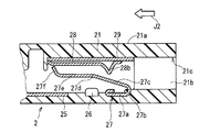
- FIG. 2 is a sectional view showing the structure of the female connector 2 employed in this embodiment.
- there is a portion showing a side surface that does not appear in the cross section (a specific portion will be described later).
- the male connector 1 can be inserted into the female connector 2 and can be electrically connected to each other. Therefore, it can be understood that both constitute a connection device that is electrically connected to each other.
- the structure of the male connector 1 will be described with reference to FIG.
- the male connector 1 is inserted into the female connector 2.
- the mode of the insertion will be described later.
- the male connector 1 includes a plurality of rod-shaped conductors 11 and a support body 13 that supports the conductors 11.
- FIG. 1 shows a cross section of one conductor 11.
- a wire bundle called a wire harness is connected to the male connector 1 from the outside to a plurality of conductors 11. Since this connection mode is a known technique, the wiring bundle and its connection mode are not shown.
- the conductor 11 has a tip 11s and a root 11e.
- the direction from the root 11e toward the tip 11s is shown as a first direction J1.
- the direction in which the male connector 1 faces the female connector 2 coincides with the first direction J1.
- the first direction J1 is taken to the left in the drawing (see the block arrow).
- the support 13 supports the conductor 11 at the root 11e.
- a cylindrical housing 12 is provided on the support 13 on the first direction J1 side, and an inner surface 12a of the housing 12 substantially accommodates the conductor 11.
- “substantially” is because the tip 11 s of the conductor 11 opposite to the support 13 (that is, the first direction J1 side) is assumed not to be housed in the housing 12.
- the surface of the support 13 on the housing 12 side can also be regarded as a recess bottom surface 12b that forms a recess that opens in the first direction J1 together with the inner surface 12a.
- the root 11e of the conductor 11, that is, the portion of the conductor 11 on the opposite side of the tip 11s is supported by the support 13 and more specifically by the recess bottom surface 12b.
- the conductor 11 is provided between the tip 11s and the root 11e, and has an intermediate portion 109 that is more fragile than the tip 11s and the root 11e.
- the conductor 11 further includes a first recess 101a that opens in a direction non-parallel to the first direction J1 on the tip 11s side of the intermediate portion 109.
- a mode in which the first recess 101a opens upward in the drawing (this can be said to be a direction orthogonal to the first direction J1) is illustrated.
- the conductor 11 also has a second recess 102a that opens in a direction non-parallel to the first direction J1 on the side of the root portion 11e from the intermediate portion 109.
- the second recess 102a and the first recess 101a open in opposite directions.
- released downward it can also be said that it is a direction orthogonal to the 1st direction J1) in drawing is illustrated.
- the intermediate portion 109 is sandwiched between the first concave portion 101a and the second concave portion 102a and is thinner than both the tip 11s and the root portion 11e. However, it is not essential in this embodiment that the second recess 102a and the intermediate portion 109 are thin. These characteristics are examples of shapes in which the intermediate portion 109 is weaker than the tip 11s and the root 11e.
- the surface of the conductor 11 on the side where the first recess 101a opens has the surface 101 on the tip 11s side with respect to the first recess 101a and the surface 103 on the root 11e side with respect to the intermediate portion 109.
- the surface of the conductor 11 on the side where the second recess 102a opens has a surface 102 closer to the tip 11s than the second recess 102a, and a surface 104 closer to the root 11e than the intermediate portion 109.
- the intermediate portion 109 is a direction that is not parallel to the first direction J1, more specifically, a direction in which the first recess 101a opens (for example, this is a direction orthogonal to the first direction J1). It is desirable to have flexibility toward
- the structure of the female connector 2 will be described with reference to FIG.
- the female connector 2 receives a conductor 11 inserted from the male connector 1 along the insertion direction J2.
- the insertion direction J2 is taken leftward in the drawing (see the block arrow). The insertion will be described later.
- the female connector 2 includes a plurality of pairs of conductive first contacts 27 and second contacts 28, and a housing 21 that supports the first contacts 27 and the second contacts 28.
- the second contact 28 faces the first contact 27 in a direction non-parallel to the insertion direction J2.
- a pair of the first contact point 27 and the second contact point 28 is shown, and the first contact point 27 and the second contact point 28 forming a pair are in the vertical direction (direction orthogonal to the insertion direction J2) in the drawing. Opposing aspects are illustrated.
- the housing 21 is cylindrical and has an outer surface 21a and an inner surface 21b.
- the housing 21 has an opening 21c that opens on the side opposite to the insertion direction J2.
- the inner side surface 21b a portion that does not appear in the cross section is not hatched.
- the first contact point 27 has flexibility in a direction away from the second contact point 28, and has elasticity that is biased in a direction toward the second contact point 28.
- the first contact 27 includes a base portion 27a supported by the inner surface 21b, a first bent portion 27b, a contacted portion 27c, a second bent portion 27d, a connecting portion 27e, and a tip 27f.
- the first bent portion 27b, the contacted portion 27c, the second bent portion 27d, and the connecting portion 27e are arranged in this order in the direction from the base portion 27a to the distal end 27f.
- the contacted portion 27 c has a function of contacting the conductor 11, more specifically, the surface 102 of the conductor 11.
- the first bent portion 27b has flexibility to narrow the space between the base portion 27a and the contacted portion 27c, but has elasticity to urge in the direction of expanding the space between them.
- the connecting portion 27e connects the tip 27f and the second bent portion 27d.
- the second bent portion 27d has the flexibility of enlarging the space between the connecting portion 27e and the contacted portion 27c, but also has the elasticity of biasing in the direction of narrowing the space between them.
- the above flexibility and elasticity of the first contact point 27 can be realized by the functions of the first bent portion 27b and the second bent portion 27d.
- the configuration of the first contact point 27 is merely an example, and having the first bent portion 27b and the second bent portion 27d is not an indispensable matter for realizing the flexibility and elasticity.
- the first contact 27 provides continuity with the conductor 11 inserted from the opening 21c. And the 1st contact 27 contacts with the conductor 25 provided in the inner surface 21b, and the electroconductivity between both is obtained.
- the second contact 28 may be electrically connected to the conductor 25 at a position not shown, and the second contact 28 may also be brought into contact with the conductor 11 to contribute to conduction between the conductor 11 and the conductor 25.
- a wire bundle called a wire harness is connected to the conductor 25 from the outside of the female connector 2. Since this connection mode is a known technique, illustration of the wiring and its connection mode is omitted. Although the portion 26 which is not hatched because it does not appear in the cross section can be used for the connection, the wiring bundle and its connection mode are not shown in order to avoid the trouble of drawing.
- the second contact 28 has a protruding portion 28 b that protrudes in the direction toward the first contact 27.
- the protruding portion 28 b is fitted into the first recess 101 a of the conductor 11, the conductor 11 and the second contact 28 are locked.
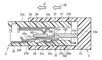
- FIG. 3 is a sectional view showing an initial state in which the conductor 11 is inserted into the opening 21c along the insertion direction J2 and the male connector 1 is inserted into the female connector 2.
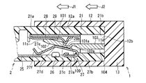
- FIG. 4 is a cross-sectional view showing a situation in which the male connector 1 has been inserted into the female connector 2.
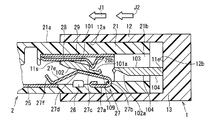
- FIG. 5 is a cross-sectional view showing a situation when the male connector 1 is removed from the female connector 2 after the insertion is completed. In the insertion, the inner surface 12a surrounds the outer surface 21a.
- FIGS. 1 and 2 there is a portion showing a side surface that does not appear in the cross section.
- the male connector 1 is inserted into the female connector 2 while the first direction J1 in which the conductor 11 extends matches the insertion direction J2.
- the tip 11s moves the first contact 27, in particular, the second bent portion 27d to the side opposite to the second contact 28, while the conductor 11 is inserted in the insertion direction J2.
- the first contact 27 and the second contact 28 serve to guide the insertion of the conductor 11.
- the first contact 27 urges the conductor 11 to the second contact 28.
- Such urging includes elasticity in which the first bent portion 27b urges the base 27a and the contacted portion 27c in a widening direction, and the second bent portion 27d narrows the connection portion 27e and the contacted portion 27c. It derives from the elasticity that urges to.
- the protruding portion 28b is positioned on the side of the insertion direction J2 rather than the first recess 101a, and therefore they are not fitted.
- the state in which the male connector 1 is further advanced in the insertion direction J2 than the state shown in FIG. 3 is shown, and the first recess 101a and the protruding portion 28b are fitted.
- the tip 11 s moves toward the second contact 28 by the fitting and the above-described urging.
- the surface 101 is in contact with the second contact 28 and becomes conductive.
- the surface 102 is brought into contact with the first contact point 27, more specifically, the contacted portion 27c.
- the conductor 11 bends in the vicinity of the intermediate portion 109 as shown in FIG.
- the bending is not essential in this embodiment. Even if such bending does not occur, the conductor 11 can be electrically connected to the conductor 25 if the surface 102 contacts the non-contact portion 2 c and the tip 27 f contacts the conductor 25.
- the surface 104 may contact the first contact point 27.
- a structure in which the second contact 28 is in contact with the surface 103 may be employed as long as the fitting between the first recess 101a and the protrusion 28b is not hindered.
- the male connector 1 is advanced in the direction opposite to the insertion direction J2 from the state shown in FIG. 4 (that is, the male connector 1 is pulled out from the female connector 2). It is shown.
- the first concave portion 101a and the protruding portion 28b are locked against the extraction, but the intermediate portion 109 is broken by such extraction because the intermediate portion 109 is weaker than the tip 11s and the root portion 11e.
- the intermediate portion 109 is pulled out from the female connector 2 in a state where the first recess 101 a is locked in the female connector 2, whereby the conductor 11 is broken at the intermediate portion 109.
- tip 11s to the 1st recessed part 101a among the conductors 11 can be left in the female connector which has the female connector 2.
- FIG. This is desirable from the viewpoint of making it difficult to connect to the female connector 2 using a new male connector.
- the first contact point 27 provides continuity with the conductor 11 inserted from the opening 21c, and the protrusion 28b is fitted to the conductor 11 provided with the first recess 101a.
- the conductor 11 and the second contact 28 are locked. This is desirable from the viewpoint of causing the second contact 28 to break the conductor 11 at the intermediate portion 109 when the male connector 1 is pulled out from the female connector 2. That is, it is difficult to replace and reconnect the male connector 1 once inserted into the female connector 2, which is desirable from the viewpoint of preventing theft of the vehicle, for example.
- 6 and 7 are block diagrams showing communication inside the vehicle using the male connector 1 and the female connector 2.
- the male connector 1 and the female connector 2 constitute a connection device 10.
- 6 shows a state in which the male connector 1 and the female connector 2 are inserted
- FIG. 7 shows that the male connector 1 (which has already been inserted into the female connector 2) is pulled from the female connector 2.
- the extracted state is shown respectively.
- the star in FIG. 7 indicates that the female connector 2 has become non-conductive due to the above-described breakage.
- the male connector 1 is provided in a regular ECU (Electronic Control Unit) 3 such as an immobilizer.
- the male connector 1 is built in the ECU 3.
- the ECU 3 is supplied with operating power from a power supply box (indicated as “power supply box” in the figure) 4 through the male connector 1 and the female connector 2 fitted therein.
- the female connector 2 is connected to the gateway ECU 5 via the wire harness 7.
- the ECU 3 can communicate with a gateway ECU (indicated as “G / W ECU” in the figure) 5 via the male connector 1, the female connector 2, and the wire harness 7.
- the gateway ECU 5 can communicate with a display meter 6 (indicated as “MET” in the drawing) via the wire harness 8.
- the communication includes information about whether or not the operation power is supplied to the ECU 3. For example, by design so that the voltage of the operating power supply to the ECU 3 appears in the male connector 1, such information transmission can be realized.
- the ECU 3 can be grasped as a vehicle control device, and the gateway ECU 5 can be grasped as a vehicle device different from the vehicle control device.
- the gateway ECU 5 Since the operating power is not supplied to the ECU 3 in the female connector 2, the gateway ECU 5 recognizes the information via the wire harness 7 and transmits this information to the display meter 6 via the wire harness 8. Based on this information, the display meter 6 performs a warning for the user, for example, lighting of a lamp. This allows the user to know that there has been an unauthorized access attempt.
- this embodiment can be realized by improving the components attached to the wire harness 7 without adding a circuit such as a detection unit. And even if ECU3 itself which incorporates the male connector 1 is removed from the female connector 2 provided in the wire harness 7, unauthorized access can be prevented and detected.
- FIG. 4 illustrates a situation where the bottom surface 12b of the recess is in contact with the housing 21 while the protrusion 28b is in contact with the side surface of the first recess 101a on the tip 11s side.
- the width (hereinafter referred to as “first width”) of the protrusion 28b in the insertion direction J2 is larger than the width (second width) of the first recess 101a in the insertion direction J2. If narrow, the conductor 11 can advance in the insertion direction J2 until the protruding portion 28b contacts the side surface of the first recess 101a on the root 11e side.
- the concave bottom surface 12b of the male connector 1 abuts on the female connector 2 before the protrusion 28b and the first concave portion 101a are fitted. To the extent that it does not, the space between the first recess 101a and the recess bottom surface 12b must be wide.
- the intermediate portion 109 is broken, so that the conductor 11 and the conductor 11 are connected thereto.
- the tensile strength between the wiring and the tensile strength between the conductor 25 and the wiring connected thereto is not directly related to the vulnerability of the intermediate portion 109. That is, the intermediate portion 109 is not damaged in the pull confirmation between the male connector 1 and the wiring to be connected thereto or the pull confirmation between the female connector 2 and the wiring to be connected thereto. In other words, although it does not break in the pull confirmation about the wiring with respect to the male side connector 1 or the female side connector 2, if the male side connector 1 or the female side connector 2 is pulled out after being once inserted and inserted, the intermediate portion 109 is broken.
- the ECU 3 may incorporate the female connector 2 and the male connector 1 may be provided in the wire harness 7.
Landscapes
- Engineering & Computer Science (AREA)
- Mechanical Engineering (AREA)
- Details Of Connecting Devices For Male And Female Coupling (AREA)
Abstract
車両装置に接続されるメス側コネクタ(2)に対して、一旦嵌挿したオス側コネクタ(1)を入れ替えて再接続することを困難にする。オス側コネクタ(1)は車両装置とは異なる車両制御装置(3)に設けられる。オス側コネクタ(1)は、先端(11s)と、根部(11e)と、先端(11s)と根部(11e)との間に設けられて先端(11s)及び根部(11e)よりも脆弱な中間部(109)と、中間部(109)よりも先端(11s)側において根部(11e)から先端(11s)に向かう第1方向に対して直交する方向で開口する第1凹部(101a)とを有する棒状の導電体(11)と、根部(11e)を支持する支持体(13)とを備える。
Description
この発明は、メス側コネクタに嵌挿されたオス側コネクタの入れ替えを防止する技術に関し、例えば盗難防止に資する。
車両のメンテナンスにはOBD(On-Board Diagnostics)と称される機能が採用される。当該機能は、診断により故障を発見した場合に、当該故障の箇所や内容をユーザに了知する。
現状、このOBD用に用いられるコネクタを介して車両制御用のデータの書き換えが可能である。よってイモビライザの解除などによって当該コネクタに対して不正にアクセスすることにより、車両が盗難される恐れがある。
かかる不正なアクセスに対処する技術を開示する文献として、下記の特許文献1,2を挙げる。
しかし特許文献1に開示された技術では、不正操作判断部を備えるセキュリティ用電子制御装置それ自体が交換されると不正を検知できない。また特許文献2に開示された技術では、正規の搭載位置にイモビライザが設置されなければ車両を作動させることができないものの、正規のイモビライザを不正のイモビライザに交換すれば車両の盗難の恐れがある。
かかる不正アクセスは先進運転支援機能が発展し、車両の電子制御が高度化する将来においては、車両の暴走など意図的な誤作動の発生の可能性もある。
そこで本発明は、メス側コネクタに対して一旦嵌挿したオス側コネクタを入れ替えて再接続することを困難にし、以て盗難を防止することを目的とする。
第1の態様にかかるメス側コネクタは車両装置に接続され、前記車両装置とは異なる車両制御装置に設けられたオス側コネクタの嵌挿によって挿入される棒状の導電体を受ける。当該メス側コネクタは、可撓性を有する導電性の第1接点と、前記嵌挿の方向と直交する方向で前記第1接点と対向する導電性の第2接点と、前記第1接点及び前記第2接点を支持し、前記嵌挿の方向とは反対側に開口する開口部を有するハウジングとを備える。前記第1接点は前記第2接点に向かう方向へ付勢される弾性を有する。前記第2接点は前記第1接点に向かう方向に突出し、前記オス側コネクタを引き抜く際に前記導電体を破断する突出部を有する。
第2の態様にかかるオス側コネクタは車両制御装置に設けられ、前記車両制御装置とは異なる車両装置に接続されるメス側コネクタに嵌挿する。当該オス側コネクタは、先端と、根部と、前記先端と前記根部との間に設けられて前記先端及び前記根部よりも脆弱であって前記メス側コネクタから引き抜かれる際に破断される中間部と、前記中間部よりも前記先端側において前記根部から前記先端に向かう第1方向に対して直交する方向で開口する第1凹部とを有する棒状の導電体と、前記根部を支持する支持体とを備える。
第3の態様にかかるオス側コネクタは、第2の態様であって、前記中間部は前記第1方向と直交する方向に向かう可撓性がある。
第4の態様にかかるオス側コネクタは、第2の態様または第3の態様であって、前記導電体は、前記中間部よりも前記根部側で前記第1方向に対して直交する方向で開口する第2凹部を更に有する。前記第1凹部と前記第2凹部とは互いに反対向きに開口する。前記中間部は前記第1凹部と前記第2凹部とで挟まれて前記先端及び前記根部のいずれよりも薄肉である。
第5の態様にかかる接続装置は、第1の態様と、第2から第4の態様のいずれかとを備える。前記オス側コネクタが前記メス側コネクタに嵌挿したときには前記第1凹部と前記突出部とが嵌合する。前記第1凹部と前記突出部とが嵌合しあったときには前記嵌挿の方向と逆の方向に対して前記第1凹部と前記突出部とが係止する。
第1の態様によると、第1接点によって、開口部から挿入される導電体との導通が得られ、かつ凹部が設けられた導電体に対しては、これに突出部が嵌合することにより、導電体と第2接点とが係止する。よってオス側コネクタをメス側コネクタから引き抜く際に導電体が破断する。これによりメス側コネクタには導電体の一部が残り、メス側コネクタに対して一旦嵌挿したオス側コネクタを入れ替えて再接続することを困難とし、以て盗難が防止される。
第2の態様によると、中間部は先端及び根部よりも脆弱なので、メス側コネクタにおいて第1凹部が係止された状態でメス側コネクタから引き抜かれることで、中間部で導電体が破断し、先端をメス側コネクタを有するメス側のコネクタに残すことができる。よって他のオス側コネクタを用いたメス側コネクタへの接続を困難にし、以て盗難が防止される。
第3の態様によると、中間部は先端及び根部よりも可撓性が高いので、第1凹部をメス側コネクタにおいて係止させることが容易である。
第4の態様によると、中間部は第1凹部と第2凹部とで挟まれ、かつ薄肉であるので、先端及び根部よりも脆弱である。
第5の態様によると、メス側コネクタに対して一旦嵌挿したオス側コネクタを入れ替えて再接続することを困難にし、以て盗難が防止される。
図1はこの実施形態に採用されるオス側コネクタ1の構造を示す断面図である。図2はこの実施形態に採用されるメス側コネクタ2の構造を示す断面図である。但し説明の都合上、断面には現れない側面を示している部位がある(具体的な部位は後述する)。
オス側コネクタ1はメス側コネクタ2に嵌挿して相互に導通することが可能である。従って両者は、相互に電気的に接続される接続装置を構成する、と把握することができる。
図1を参照して、オス側コネクタ1の構造を説明する。オス側コネクタ1はメス側コネクタ2に嵌挿する。その嵌挿の態様は後述する。オス側コネクタ1は、棒状の導電体11の複数と、導電体11を支持する支持体13とを備える。図1では簡単のため、一つの導電体11についての断面を示している。
技術的常識としてオス側コネクタ1にはその外部から、例えばワイヤーハーネスと称される配線束が複数の導電体11に接続される。この接続態様は公知の技術であるので、当該配線束及びその接続態様は図示を省略した。
導電体11は先端11s、根部11eを有する。図1において根部11eから先端11sに向かう方向を第1方向J1として示す。後述するオス側コネクタ1のメス側コネクタ2への嵌挿において、オス側コネクタ1がメス側コネクタ2へ向かう方向は第1方向J1に一致する。但し図1では第1方向J1を紙面左向きに採っている(ブロック矢印参照)。
支持体13は導電体11を根部11eにおいて支持する。支持体13にはその第1方向J1側に例えば筒状のハウジング12が設けられ、ハウジング12の内側面12aは導電体11をほぼ収納する。ここで「ほぼ」としたのは、導電体11の支持体13とは反対側の(つまり第1方向J1側の)先端11sが、ハウジング12に収納されない場合も想定されるからである。
支持体13のハウジング12側の面は、内側面12aと共に第1方向J1に向けて開口する凹部を形成する、凹部底面12bとして捉えることもできる。導電体11の根部11e、つまり先端11sとは反対側での導電体11の部位が、支持体13に、より詳細には凹部底面12bによって支持される。
導電体11は先端11sと根部11eとの間に設けられて、先端11s及び根部11eよりも脆弱な中間部109を有する。導電体11は更に、中間部109よりも先端11s側において、第1方向J1に対して非平行な方向で開口する第1凹部101aをも有する。ここでは第1凹部101aは図面において上方(これは第1方向J1に直交する方向であると言える)に開口する態様が例示されている。
導電体11は中間部109よりも根部11e側に、第1方向J1に対して非平行な方向で開口する第2凹部102aをも有する。但し、第2凹部102aと第1凹部101aとは互いに反対向きに開口する。図1では第2凹部102aが図面において下方(これも第1方向J1に直交する方向であると言える)に開口する態様を呈する場合が例示されている。
中間部109は第1凹部101aと第2凹部102aとで挟まれて先端11s及び根部11eのいずれよりも薄肉である。但し、第2凹部102aの存在及び中間部109が薄肉であることはこの実施形態において必須ではない。これらの特徴は中間部109が先端11s及び根部11eよりも脆弱となる形状の一例である。
第1凹部101aが開口する側の導電体11の表面は、第1凹部101aよりも先端11s側に表面101を、中間部109よりも根部11e側に表面103を、それぞれ有する。第2凹部102aが開口する側の導電体11の表面は、第2凹部102aよりも先端11s側に表面102を、中間部109よりも根部11e側に表面104を、それぞれ有する。
第1凹部101aは、後述するメス側コネクタ2への嵌挿により、メス側コネクタ2内の突起と係止する機能を担う。この係止を容易にする観点で、中間部109は第1方向J1と非平行な方向、より具体的には第1凹部101aが開口する方向(例えばこれは第1方向J1に直交する方向)に向かう可撓性があることが望ましい。
図2を参照して、メス側コネクタ2の構造を説明する。メス側コネクタ2はオス側コネクタ1から嵌挿方向J2に沿って挿入される導電体11を受ける。図2では嵌挿方向J2を紙面左向きに採っている(ブロック矢印参照)。当該嵌挿については後述される。
メス側コネクタ2は、いずれも導電性の第1接点27及び第2接点28の複数対と、第1接点27及び第2接点28を支持するハウジング21とを備える。第2接点28は、嵌挿方向J2と非平行な方向で第1接点27と対向する。ここでは簡単のため第1接点27及び第2接点28の一対について示しており、対をなす第1接点27と第2接点28とは図面において上下方向(嵌挿方向J2と直交する方向)に対向する態様が例示されている。
例えばハウジング21は筒状であり、外側面21a及び内側面21bを有する。ハウジング21は嵌挿方向J2とは反対側に開口する開口部21cを有する。内側面21bのうち、断面に現れない部位にはハッチングを施していない。
第1接点27は、第2接点28から離れる方向への可撓性を有し、第2接点28に向かう方向へ付勢される弾性を有する。具体的には例えば、第1接点27は、内側面21bで支持される基部27a、第1屈曲部27b、被接触部27c、第2屈曲部27d、連結部27e、先端27fを有する。第1屈曲部27b、被接触部27c、第2屈曲部27d、連結部27eはこの順に従って、基部27aから先端27fへ向かう方向に配置される。
被接触部27cは導電体11と、より具体的には導電体11の表面102と接触する機能を担う。第1屈曲部27bは基部27aと被接触部27cとの間を狭める可撓性を有しつつも、それらの間を広げる方向に付勢する弾性を有する。
連結部27eは先端27fと第2屈曲部27dとを連結する。第2屈曲部27dは連結部27eと被接触部27cとの間を広げる可撓性を有しつつも、それらの間を狭める方向に付勢する弾性を有する。
このような第1屈曲部27bと第2屈曲部27dとの機能により、第1接点27の上記可撓性及び弾性を実現できる。もちろん、かかる第1接点27の構成は例示であり、第1屈曲部27bと第2屈曲部27dとを有することは、当該可撓性及び弾性を実現するために必須な事項ではない。
第1接点27によって、開口部21cから挿入される導電体11との導通が得られる。そして第1接点27は内側面21bに設けられた導電体25と接触することで両者の間の導電が得られる。例えば第2接点28は、図示されない位置で導電体25と導通し、第2接点28も導電体11と接触して、導電体11と導電体25との間の導通に寄与してもよい。
技術的常識としてメス側コネクタ2にはその外部から例えばワイヤーハーネスと称される配線束が導電体25に接続される。この接続態様は公知の技術であるので、当該配線及びその接続態様は図示を省略した。断面には現れないためにハッチングが施されていない部位26を、当該接続に用いることもできるが、図面の煩瑣を避けるために当該配線束及びその接続態様は図示を省略した。
第2接点28は第1接点27に向かう方向に突出する突出部28bを有する。突出部28bが導電体11の第1凹部101aと嵌合することにより、導電体11と第2接点28とが係止する。
図3は導電体11を開口部21cへと嵌挿方向J2に沿って挿入し、オス側コネクタ1をメス側コネクタ2へ嵌挿する初期の状況を示す断面図である。図4はオス側コネクタ1のメス側コネクタ2への嵌挿が終了した状況を示す断面図である。図5は嵌挿が終了した後に、オス側コネクタ1をメス側コネクタ2から取り外すときの状況を示す断面図である。当該嵌挿において、内側面12aは外側面21aを囲む。これらのいずれの図においても、図1及び図2と同様、断面には現れない側面を示している部位がある。
導電体11が延在する第1方向J1を嵌挿方向J2に一致させつつ、オス側コネクタ1をメス側コネクタ2へ嵌挿する。その初期状態では図3に示されるように、先端11sが第1接点27を、特にその第2屈曲部27dを第2接点28とは反対側へ移動させつつ、導電体11が嵌挿方向J2に進む。観点を変えれば第1接点27及び第2接点28は導電体11の挿入をガイドする機能を果たすと見ることもできる。
第1接点27は導電体11を第2接点28へと付勢する。かかる付勢は第1屈曲部27bが基部27aと被接触部27cとの間を広げる方向に付勢する弾性と、第2屈曲部27dが連結部27eと被接触部27cとの間を狭める方向に付勢する弾性とに由来する。
図3に示された状況では、第1凹部101aよりも突出部28bの方が嵌挿方向J2側に位置しており、従って両者は嵌合していない。図4に示された状態では、図3に示された状態よりも更にオス側コネクタ1を嵌挿方向J2に進めた状態が示されており、第1凹部101aと突出部28bとが嵌合する。かかる嵌合と上述の付勢により、先端11sは第2接点28へ向かって移動する。表面101は第2接点28と接触して導通する。表面102は第1接点27と、より具体的には被接触部27cに接触して導通する。
中間部109が第1凹部101aの開口する方法に向かう可撓性を有する場合、導電体11は図4に示されるように中間部109近傍で屈曲する。但しこの実施形態において当該屈曲は必須ではない。かかる屈曲が発生しなくても、表面102が非接触部2cに接触し、先端27fが導電体25と接触すれば、導電体11は導電体25との導通が得られるからである。
導電体11が上述の様に屈曲する場合、表面104が第1接点27に接触してもよい。第1凹部101aと突出部28bとの嵌合を阻害しなければ、第2接点28が表面103と接触する構造を採用してもよい。
図5に示された状態では、図4に示された状態から、オス側コネクタ1を嵌挿方向J2とは逆の方向に進めた(つまりオス側コネクタ1をメス側コネクタ2から引き抜く)状態が示されている。第1凹部101aと突出部28bとが当該引き抜きに対抗して係止するが、中間部109が先端11s及び根部11eよりも脆弱なので、このような引き抜きによって中間部109が破断する。
つまり、中間部109はメス側コネクタ2において第1凹部101aが係止された状態でメス側コネクタ2から引き抜かれることで、中間部109で導電体11が破断する。これにより、導電体11のうち、先端11sから第1凹部101aまでの部分を、メス側コネクタ2を有するメス側のコネクタに残すことができる。これは新たなオス側コネクタを用いたメス側コネクタ2への接続を困難にする観点で望ましい。
また、第1接点27によって、開口部21cから挿入される導電体11との導通が得られ、かつ第1凹部101aが設けられた導電体11に対しては、これに突出部28bが嵌合することにより、導電体11と第2接点28とが係止する。これはオス側コネクタ1をメス側コネクタ2から引き抜く際に第2接点28が導電体11を中間部109で破断させる観点で望ましい。つまりメス側コネクタ2に対して一旦嵌挿したオス側コネクタ1を入れ替えて再接続することが困難となり、例えば車両の盗難防止の観点で望ましい。
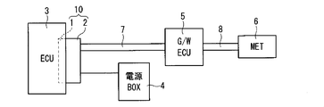
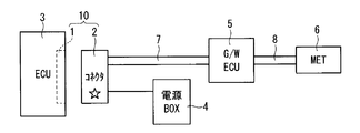
図6及び図7はオス側コネクタ1とメス側コネクタ2とを利用した、車両の内部での通信を示すブロック図である。オス側コネクタ1とメス側コネクタ2とは接続装置10を構成する。図6はオス側コネクタ1とメス側コネクタ2とが嵌挿されている状態を、図7は(既にメス側コネクタ2に嵌挿されていた)オス側コネクタ1が、メス側コネクタ2から引き抜かれた状態を、それぞれ示す。図7の星印は、上述の破断が発生してメス側コネクタ2が非導通となったことを示す。
オス側コネクタ1が、イモビライザなどの正規のECU(Electronic Control Unit:エレクトロニックコントロールユニット)3に設けられる。図6の例示ではオス側コネクタ1がECU3に内蔵されている。ECU3には、オス側コネクタ1及びこれと嵌挿するメス側コネクタ2とを介して、電源ボックス(図中「電源BOX」と表記)4から動作電源が供給される。図6の例示ではメス側コネクタ2がゲートウェイECU5にワイヤーハーネス7を介して接続されている。ECU3は、オス側コネクタ1及びメス側コネクタ2並びにワイヤーハーネス7を介して、ゲートウェイECU(図中「G/W ECU」と表記)5と通信可能である。ゲートウェイECU5はワイヤーハーネス8を介して、表示用メータ(図中「MET」と表記)6と通信可能である。当該通信には、ECU3への動作電源の供給の有無についての情報も含む。例えばECU3への動作電源の電圧がオス側コネクタ1に現れるように設計することで、かかる情報の伝達を実現できる。ECU3は車両制御装置として、またゲートウェイECU5は当該車両制御装置とは異なる車両装置として把握することができる。
図6の状態において正規のECU3を他の、例えば不正アクセス用のECUと交換するには、既にオス側コネクタ1に嵌挿されていたメス側コネクタ2を引き抜かなければならない。そして当該引き抜きによって、上記実施形態で説明されたように、オス側コネクタ1はその導電体11が破断する。これにより、オス側コネクタ1は電気的に断線したと見ることができ、よって外部に対して導通を得ることが困難となる(図中では「非導通」と表記した)。
メス側コネクタ2にはECU3へ動作電源が供給されていないので、ゲートウェイECU5はワイヤーハーネス7を介してその情報を了知し、ワイヤーハーネス8を介してこれを表示用メータ6に伝達する。表示用メータ6はこの情報に基づいてユーザへ警告のための報知、例えばランプの点灯等を行う。これによりユーザは不正アクセスの試みがあったことを知ることができる。
メス側コネクタ2には既に、導電体11のうち先端11sから中間部109に至る部分が残っているので、不正アクセス用のECUを改めてメス側コネクタ2に接続することは困難である。また不正アクセス用のECUの取付を断念して、元の正規のECU3のオス側コネクタ1をメス側コネクタ2へ嵌挿しても、中間部109が既に破断しているので、両者の間での導通をとることも困難となる。よって不正アクセスの試みがあっても、車両の盗難にまでいたる事案は発生しない。
以上のように本実施形態は、検知ユニットなどの回路を追加すること無く、ワイヤーハーネス7に付属する部品を改良することで実現できる。しかもオス側コネクタ1を内蔵するECU3それ自体が、ワイヤーハーネス7に設けられたメス側コネクタ2から外された場合であっても、不正アクセスを防止、検知することができる。
{変形例}
図4では突出部28bが第1凹部101aの先端11s側の側面と当接している状態で、凹部底面12bがハウジング21と当接している状況が例示された。但し、図4から理解される様に、突出部28bの嵌挿方向J2における幅(以下「第1幅」と称す)が第1凹部101aの嵌挿方向J2における幅(第2幅)よりも狭ければ、突出部28bが第1凹部101aの根部11e側の側面と当接するまで、導電体11は嵌挿方向J2へと進むことができる。よって突出部28bが第1凹部101aの先端11s側の側面と当接している状態で、凹部底面12bとハウジング21との間に、第1幅と第2幅の差程度の余裕が設けられてもよい。
図4では突出部28bが第1凹部101aの先端11s側の側面と当接している状態で、凹部底面12bがハウジング21と当接している状況が例示された。但し、図4から理解される様に、突出部28bの嵌挿方向J2における幅(以下「第1幅」と称す)が第1凹部101aの嵌挿方向J2における幅(第2幅)よりも狭ければ、突出部28bが第1凹部101aの根部11e側の側面と当接するまで、導電体11は嵌挿方向J2へと進むことができる。よって突出部28bが第1凹部101aの先端11s側の側面と当接している状態で、凹部底面12bとハウジング21との間に、第1幅と第2幅の差程度の余裕が設けられてもよい。
もちろん、オス側コネクタ1をメス側コネクタ2へ嵌挿する際に、突出部28bと第1凹部101aとが嵌合する前に、オス側コネクタ1の凹部底面12bがメス側コネクタ2に当接しない程度には、第1凹部101aと凹部底面12bとの間隔を広く採らなければならない。
また、支持体13に支持された導電体11と、ハウジング21で支持された第2接点28とが係止した後に、中間部109が破断するのであるから、導電体11とこれに接続される配線との引っ張り強度や、導電体25とこれに接続される配線との引っ張り強度は、中間部109の脆弱性とは直接の関係はない。つまりオス側コネクタ1とこれに接続されるべき配線との間の引っ張り確認や、メス側コネクタ2とこれに接続されるべき配線との間の引っ張り確認では、中間部109は損傷しない。換言すれば、オス側コネクタ1やメス側コネクタ2に対する配線についての引っ張り確認では破断しないものの、一旦嵌挿した後にオス側コネクタ1やメス側コネクタ2を引き抜くと、中間部109が破断する。
また図6、図7において、ECU3がメス側コネクタ2を内蔵し、ワイヤーハーネス7にオス側コネクタ1を設けてもよい。
なお、上記実施形態及び各変形例で説明した各構成は、相互に矛盾しない限り適宜組合わせることができる。
以上のようにこの発明は詳細に説明されたが、上記した説明は、すべての局面において、例示であって、この発明がそれに限定されるものではない。例示されていない無数の変形例が、この発明の範囲から外れることなく想定され得るものと解される。
1 オス側コネクタ
2 メス側コネクタ
3 車両制御装置(ECU)
5 車両装置(ゲートウェイECU)
10 接続装置
11 導電体
11e 根部
11s 先端
13 支持体
21 ハウジング
21c 開口部
27 第1接点
28 第2接点
28b 突出部
101a 第1凹部
102a 第2凹部
109 中間部
2 メス側コネクタ
3 車両制御装置(ECU)
5 車両装置(ゲートウェイECU)
10 接続装置
11 導電体
11e 根部
11s 先端
13 支持体
21 ハウジング
21c 開口部
27 第1接点
28 第2接点
28b 突出部
101a 第1凹部
102a 第2凹部
109 中間部
Claims (5)
- 車両制御装置に設けられたオス側コネクタの嵌挿によって挿入される棒状の導電体を受ける、前記車両制御装置とは異なる車両装置に接続されたメス側コネクタであって、
可撓性を有する導電性の第1接点と、
前記嵌挿の方向と直交する方向で前記第1接点と対向する導電性の第2接点と、
前記第1接点及び前記第2接点を支持し、前記嵌挿の方向とは反対側に開口する開口部を有するハウジングと
を備え、
前記第1接点は前記第2接点に向かう方向へ付勢される弾性を有し、
前記第2接点は前記第1接点に向かう方向に突出し、前記オス側コネクタを引き抜く際に前記導電体を破断する突出部を有する、メス側コネクタ。 - 車両装置に接続されるメス側コネクタに嵌挿する、前記車両装置とは異なる車両制御装置に設けられるオス側コネクタであって、
先端と、根部と、前記先端と前記根部との間に設けられて前記先端及び前記根部よりも脆弱であって前記メス側コネクタから引き抜かれる際に破断される中間部と、前記中間部よりも前記先端側において前記根部から前記先端に向かう第1方向に対して直交する方向で開口する第1凹部とを有する棒状の導電体と、
前記根部を支持する支持体と
を備える、オス側コネクタ。 - 請求項2に記載のオス側コネクタであって、
前記中間部は前記第1方向と直交する方向に向かう可撓性がある、オス側コネクタ。 - 請求項2又は請求項3に記載のオス側コネクタであって、
前記導電体は、
前記中間部よりも前記根部側で前記第1方向に対して直交する方向で開口する第2凹部
を更に有し、
前記第1凹部と前記第2凹部とは互いに反対向きに開口し、
前記中間部は前記第1凹部と前記第2凹部とで挟まれて前記先端及び前記根部のいずれよりも薄肉である、オス側コネクタ。 - 請求項1に記載のメス側コネクタと、
請求項2から請求項4のいずれか一項に記載のオス側コネクタと
を備える接続装置であって、
前記オス側コネクタが前記メス側コネクタに嵌挿したときには前記第1凹部と前記突出部とが嵌合し、
前記第1凹部と前記突出部とが嵌合しあったときには前記嵌挿の方向と逆の方向に対して前記第1凹部と前記突出部とが係止する、接続装置。
Applications Claiming Priority (2)
| Application Number | Priority Date | Filing Date | Title |
|---|---|---|---|
| JP2016049095A JP2017168187A (ja) | 2016-03-14 | 2016-03-14 | オス側コネクタ及びメス側コネクタ、接続装置 |
| JP2016-049095 | 2016-03-14 |
Publications (1)
| Publication Number | Publication Date |
|---|---|
| WO2017159285A1 true WO2017159285A1 (ja) | 2017-09-21 |
Family
ID=59851880
Family Applications (1)
| Application Number | Title | Priority Date | Filing Date |
|---|---|---|---|
| PCT/JP2017/007016 Ceased WO2017159285A1 (ja) | 2016-03-14 | 2017-02-24 | オス側コネクタ、メス側コネクタ、接続装置 |
Country Status (2)
| Country | Link |
|---|---|
| JP (1) | JP2017168187A (ja) |
| WO (1) | WO2017159285A1 (ja) |
Cited By (1)
| Publication number | Priority date | Publication date | Assignee | Title |
|---|---|---|---|---|
| WO2021193729A1 (ja) * | 2020-03-26 | 2021-09-30 | 株式会社カネカ | ケーブル接続具 |
Citations (4)
| Publication number | Priority date | Publication date | Assignee | Title |
|---|---|---|---|---|
| JPS58212081A (ja) * | 1982-06-04 | 1983-12-09 | 日産自動車株式会社 | 雌タ−ミナル |
| JP2006263336A (ja) * | 2005-03-25 | 2006-10-05 | Olympia:Kk | 遊技機 |
| JP2009059664A (ja) * | 2007-09-03 | 2009-03-19 | Sumitomo Wiring Syst Ltd | コネクタの抜き取り防止装置 |
| JP2010534398A (ja) * | 2007-07-25 | 2010-11-04 | ヒューレット−パッカード デベロップメント カンパニー エル.ピー. | 不正変更明示型コネクタ |
-
2016
- 2016-03-14 JP JP2016049095A patent/JP2017168187A/ja active Pending
-
2017
- 2017-02-24 WO PCT/JP2017/007016 patent/WO2017159285A1/ja not_active Ceased
Patent Citations (4)
| Publication number | Priority date | Publication date | Assignee | Title |
|---|---|---|---|---|
| JPS58212081A (ja) * | 1982-06-04 | 1983-12-09 | 日産自動車株式会社 | 雌タ−ミナル |
| JP2006263336A (ja) * | 2005-03-25 | 2006-10-05 | Olympia:Kk | 遊技機 |
| JP2010534398A (ja) * | 2007-07-25 | 2010-11-04 | ヒューレット−パッカード デベロップメント カンパニー エル.ピー. | 不正変更明示型コネクタ |
| JP2009059664A (ja) * | 2007-09-03 | 2009-03-19 | Sumitomo Wiring Syst Ltd | コネクタの抜き取り防止装置 |
Cited By (3)
| Publication number | Priority date | Publication date | Assignee | Title |
|---|---|---|---|---|
| WO2021193729A1 (ja) * | 2020-03-26 | 2021-09-30 | 株式会社カネカ | ケーブル接続具 |
| JPWO2021193729A1 (ja) * | 2020-03-26 | 2021-09-30 | ||
| JP7667135B2 (ja) | 2020-03-26 | 2025-04-22 | 株式会社カネカ | ケーブル接続具 |
Also Published As
| Publication number | Publication date |
|---|---|
| JP2017168187A (ja) | 2017-09-21 |
Similar Documents
| Publication | Publication Date | Title |
|---|---|---|
| CN102282732B (zh) | 接地用连接器及包含该接地用连接器的线束 | |
| JP4843682B2 (ja) | コンタクティング差込み接続装置 | |
| CN105789976B (zh) | 连接器 | |
| CN106340771B (zh) | 用于安全约束系统的电插头连接器 | |
| CN105576445B (zh) | 连接器及连接器组件 | |
| JP2009259442A (ja) | コネクタ | |
| EP1986283A1 (en) | A connector and an assembling method therefor | |
| CN102544856A (zh) | 连接部件 | |
| JP2016001579A (ja) | 導電端子 | |
| US9843132B2 (en) | Cable strain relief | |
| JP2008300286A (ja) | 嵌合検知コネクタ | |
| CN107534257A (zh) | 接头连接器 | |
| KR102454220B1 (ko) | 커넥터 어셈블리 | |
| WO2017217208A1 (ja) | コネクタ | |
| WO2017159285A1 (ja) | オス側コネクタ、メス側コネクタ、接続装置 | |
| CN111653889B (zh) | 一种防触指结构及尾部设置防触指结构的插座连接器 | |
| KR102843254B1 (ko) | 커넥터 모듈 | |
| CN107230885B (zh) | 带锁定机构的连接器 | |
| US7862368B1 (en) | Socket assembly | |
| JP2007172931A (ja) | コネクタ | |
| CN106058577B (zh) | 连接器组件 | |
| JP2010055940A (ja) | ワイヤハーネスのコネクタホルダ並びにワイヤハーネスの製造方法 | |
| JP2017037732A (ja) | 嵌合検知機能を有する電気接続装置 | |
| JP2005100848A (ja) | ケーブル接続部構造 | |
| JP2010096742A (ja) | 車両に搭載された電装システムのチェック装置 |
Legal Events
| Date | Code | Title | Description |
|---|---|---|---|
| NENP | Non-entry into the national phase |
Ref country code: DE |
|
| 121 | Ep: the epo has been informed by wipo that ep was designated in this application |
Ref document number: 17766290 Country of ref document: EP Kind code of ref document: A1 |
|
| 122 | Ep: pct application non-entry in european phase |
Ref document number: 17766290 Country of ref document: EP Kind code of ref document: A1 |