WO2017158950A1 - 蓄電装置パック - Google Patents
蓄電装置パック Download PDFInfo
- Publication number
- WO2017158950A1 WO2017158950A1 PCT/JP2016/086229 JP2016086229W WO2017158950A1 WO 2017158950 A1 WO2017158950 A1 WO 2017158950A1 JP 2016086229 W JP2016086229 W JP 2016086229W WO 2017158950 A1 WO2017158950 A1 WO 2017158950A1
- Authority
- WO
- WIPO (PCT)
- Prior art keywords
- power storage
- heat transfer
- storage device
- heat
- housing
- Prior art date
- Legal status (The legal status is an assumption and is not a legal conclusion. Google has not performed a legal analysis and makes no representation as to the accuracy of the status listed.)
- Ceased
Links
Images



Classifications
-
- H—ELECTRICITY
- H01—ELECTRIC ELEMENTS
- H01M—PROCESSES OR MEANS, e.g. BATTERIES, FOR THE DIRECT CONVERSION OF CHEMICAL ENERGY INTO ELECTRICAL ENERGY
- H01M10/00—Secondary cells; Manufacture thereof
- H01M10/60—Heating or cooling; Temperature control
- H01M10/65—Means for temperature control structurally associated with the cells
- H01M10/655—Solid structures for heat exchange or heat conduction
- H01M10/6554—Rods or plates
- H01M10/6555—Rods or plates arranged between the cells
-
- H—ELECTRICITY
- H01—ELECTRIC ELEMENTS
- H01G—CAPACITORS; CAPACITORS, RECTIFIERS, DETECTORS, SWITCHING DEVICES, LIGHT-SENSITIVE OR TEMPERATURE-SENSITIVE DEVICES OF THE ELECTROLYTIC TYPE
- H01G11/00—Hybrid capacitors, i.e. capacitors having different positive and negative electrodes; Electric double-layer [EDL] capacitors; Processes for the manufacture thereof or of parts thereof
- H01G11/10—Multiple hybrid or EDL capacitors, e.g. arrays or modules
-
- H—ELECTRICITY
- H01—ELECTRIC ELEMENTS
- H01G—CAPACITORS; CAPACITORS, RECTIFIERS, DETECTORS, SWITCHING DEVICES, LIGHT-SENSITIVE OR TEMPERATURE-SENSITIVE DEVICES OF THE ELECTROLYTIC TYPE
- H01G11/00—Hybrid capacitors, i.e. capacitors having different positive and negative electrodes; Electric double-layer [EDL] capacitors; Processes for the manufacture thereof or of parts thereof
- H01G11/14—Arrangements or processes for adjusting or protecting hybrid or EDL capacitors
- H01G11/18—Arrangements or processes for adjusting or protecting hybrid or EDL capacitors against thermal overloads, e.g. heating, cooling or ventilating
-
- H—ELECTRICITY
- H01—ELECTRIC ELEMENTS
- H01G—CAPACITORS; CAPACITORS, RECTIFIERS, DETECTORS, SWITCHING DEVICES, LIGHT-SENSITIVE OR TEMPERATURE-SENSITIVE DEVICES OF THE ELECTROLYTIC TYPE
- H01G2/00—Details of capacitors not covered by a single one of groups H01G4/00-H01G11/00
- H01G2/02—Mountings
- H01G2/04—Mountings specially adapted for mounting on a chassis
-
- H—ELECTRICITY
- H01—ELECTRIC ELEMENTS
- H01M—PROCESSES OR MEANS, e.g. BATTERIES, FOR THE DIRECT CONVERSION OF CHEMICAL ENERGY INTO ELECTRICAL ENERGY
- H01M10/00—Secondary cells; Manufacture thereof
- H01M10/60—Heating or cooling; Temperature control
- H01M10/61—Types of temperature control
- H01M10/613—Cooling or keeping cold
-
- H—ELECTRICITY
- H01—ELECTRIC ELEMENTS
- H01M—PROCESSES OR MEANS, e.g. BATTERIES, FOR THE DIRECT CONVERSION OF CHEMICAL ENERGY INTO ELECTRICAL ENERGY
- H01M10/00—Secondary cells; Manufacture thereof
- H01M10/60—Heating or cooling; Temperature control
- H01M10/64—Heating or cooling; Temperature control characterised by the shape of the cells
- H01M10/647—Prismatic or flat cells, e.g. pouch cells
-
- H—ELECTRICITY
- H01—ELECTRIC ELEMENTS
- H01M—PROCESSES OR MEANS, e.g. BATTERIES, FOR THE DIRECT CONVERSION OF CHEMICAL ENERGY INTO ELECTRICAL ENERGY
- H01M10/00—Secondary cells; Manufacture thereof
- H01M10/60—Heating or cooling; Temperature control
- H01M10/65—Means for temperature control structurally associated with the cells
- H01M10/655—Solid structures for heat exchange or heat conduction
- H01M10/6554—Rods or plates
-
- H—ELECTRICITY
- H01—ELECTRIC ELEMENTS
- H01M—PROCESSES OR MEANS, e.g. BATTERIES, FOR THE DIRECT CONVERSION OF CHEMICAL ENERGY INTO ELECTRICAL ENERGY
- H01M50/00—Constructional details or processes of manufacture of the non-active parts of electrochemical cells other than fuel cells, e.g. hybrid cells
- H01M50/20—Mountings; Secondary casings or frames; Racks, modules or packs; Suspension devices; Shock absorbers; Transport or carrying devices; Holders
- H01M50/204—Racks, modules or packs for multiple batteries or multiple cells
- H01M50/207—Racks, modules or packs for multiple batteries or multiple cells characterised by their shape
- H01M50/209—Racks, modules or packs for multiple batteries or multiple cells characterised by their shape adapted for prismatic or rectangular cells
-
- H—ELECTRICITY
- H01—ELECTRIC ELEMENTS
- H01M—PROCESSES OR MEANS, e.g. BATTERIES, FOR THE DIRECT CONVERSION OF CHEMICAL ENERGY INTO ELECTRICAL ENERGY
- H01M50/00—Constructional details or processes of manufacture of the non-active parts of electrochemical cells other than fuel cells, e.g. hybrid cells
- H01M50/20—Mountings; Secondary casings or frames; Racks, modules or packs; Suspension devices; Shock absorbers; Transport or carrying devices; Holders
- H01M50/262—Mountings; Secondary casings or frames; Racks, modules or packs; Suspension devices; Shock absorbers; Transport or carrying devices; Holders with fastening means, e.g. locks
- H01M50/264—Mountings; Secondary casings or frames; Racks, modules or packs; Suspension devices; Shock absorbers; Transport or carrying devices; Holders with fastening means, e.g. locks for cells or batteries, e.g. straps, tie rods or peripheral frames
-
- Y—GENERAL TAGGING OF NEW TECHNOLOGICAL DEVELOPMENTS; GENERAL TAGGING OF CROSS-SECTIONAL TECHNOLOGIES SPANNING OVER SEVERAL SECTIONS OF THE IPC; TECHNICAL SUBJECTS COVERED BY FORMER USPC CROSS-REFERENCE ART COLLECTIONS [XRACs] AND DIGESTS
- Y02—TECHNOLOGIES OR APPLICATIONS FOR MITIGATION OR ADAPTATION AGAINST CLIMATE CHANGE
- Y02E—REDUCTION OF GREENHOUSE GAS [GHG] EMISSIONS, RELATED TO ENERGY GENERATION, TRANSMISSION OR DISTRIBUTION
- Y02E60/00—Enabling technologies; Technologies with a potential or indirect contribution to GHG emissions mitigation
- Y02E60/10—Energy storage using batteries
Definitions
- One embodiment of the present invention relates to a power storage device pack.
- a battery pack described in Patent Document 1 As a power storage device pack, for example, a battery pack described in Patent Document 1 is known.
- the battery pack described in Patent Document 1 includes a plurality of stacked battery cells, a plurality of positioning plates stacked on each stacked battery cell, and a plurality of stacked battery cells and a plurality of positioning plates biased in the stacking direction. And a housing for storing a plurality of stacked battery cells, a plurality of positioning plates, and a biasing portion. The bent portion (heat radiating portion) of the positioning plate is pressed against the housing with the heat conductive sheet interposed therebetween.
- the stacked battery cell expands toward the biasing portion due to deterioration or charge / discharge of the stacked battery cell.
- the heat conductive sheet is joined to the heat radiating part and the casing of the positioning plate, respectively.
- the positioning plate also moves together, so that a load in the shear direction is applied to the heat conductive sheet.
- interface peeling between the positioning plate and the heat conductive sheet or interface peeling between the heat conductive sheet and the housing occurs, or the heat conductive sheet breaks.
- One embodiment of the present invention provides a power storage device pack capable of improving heat dissipation with respect to a housing.
- a power storage device pack includes a housing and a power storage device module fixed to the housing.
- the power storage device module includes a plurality of power storage devices arranged in one direction and a plurality of power storage devices.
- a pair of restraining members that restrain the battery from one side in both directions, an elastic member that absorbs expansion of the power storage device, and a plurality of power storage devices that are disposed between the restraining member and the power storage device.
- a plurality of heat transfer plates Between the plurality of heat transfer plates and the housing, a plurality of heat conduction members for transferring heat from the plurality of heat transfer plates to the housing, respectively, and one end of the plurality of heat conduction members are respectively joined to each other in one direction.
- a plurality of sliding members that are slidable are arranged.
- the sliding member may be disposed between the heat conducting member and the housing, and may be slidable in one direction relative to the housing. In this case, when the power storage device expands, the sliding member slides relative to the housing in one direction. Therefore, since the relative position between the heat transfer plate and the heat conducting member is always constant, the heat dissipation performance with respect to the housing is stabilized.
- the heat transfer plate may include a main body portion that contacts the main surface of the power storage device and a heat transfer portion that is bent in one direction from one end of the main body portion.
- the other end of the heat conducting member may be joined to the heat transfer unit, and the other end of the heat conducting member may be joined to the main body side of the heat conducting unit.
- the heat generated in the power storage device is transferred from the main body to the heat transfer section in the heat transfer plate.
- the thermal conductivity on the main body side of the heat transfer section is better than the thermal conductivity on the opposite side of the main body section in the heat transfer section.
- casing can further be improved by offsetting and joining the other end of a heat conductive member to the main-body-part side of a heat-transfer part.
- the sliding member may be disposed between the heat transfer plate and the heat transfer member, or may be slidable in one direction relative to the heat transfer plate. In this case, when manufacturing the power storage device pack, one end of each heat conducting member is joined to each sliding member, and the other end of each heat conducting member is joined to the housing. Therefore, when the power storage device module is subsequently fixed to the housing, the heat conducting member and the sliding member are unlikely to drop.
- the heat transfer plate may include a main body portion that contacts the main surface of the power storage device, and a heat transfer portion that is bent from one end of the main body portion in one direction toward the elastic member.
- a sliding member may be in contact with the heat transfer section, and the other end of the heat conducting member may be joined to the housing.
- the heat generated in the power storage device is transferred from the main body to the heat transfer section in the heat transfer plate.
- the thermal conductivity on the main body side of the heat transfer section is better than the thermal conductivity on the opposite side of the main body section in the heat transfer section. Therefore, in the heat transfer plate, when the power storage device expands by bending the heat transfer portion from one end of the main body portion toward the elastic member, the sliding member moves relative to the heat transfer portion of the heat transfer plate.
- the heat conduction member moves from the elastic member side to the main body portion side because it slides relatively from the opposite side (elastic member side) of the main body portion to the main body portion side.
- casing can further be improved.
- a power storage device pack includes a housing and a power storage device module fixed to the housing.
- the power storage device module includes a plurality of power storage devices arranged in one direction and a plurality of power storage devices.
- a pair of restraining members that restrain the battery from one side in both directions, an elastic member that is disposed between the restraining member and the power storage device, absorbs expansion of the power storage device, and heats each of the plurality of power storage devices and the housing. And a plurality of heat transfer surfaces for connection.
- a plurality of heat conducting members for transferring heat from the plurality of heat conducting surfaces to the housing, respectively, and one end of the plurality of heat conducting members are joined to each other, and relative to each other in one direction.
- a plurality of sliding members that are slidable are arranged.
- the sliding member may be disposed between the heat conducting member and the housing, and may be slidable in one direction relative to the housing. In this case, when the power storage device expands, the sliding member slides relative to the housing in one direction. Therefore, since the relative position between the heat transfer surface and the heat conducting member is always constant, the heat dissipation performance with respect to the housing is stabilized.
- the sliding member may be disposed between the heat transfer surface and the heat transfer member, or may be slidable in one direction relative to the heat transfer surface. In this case, when manufacturing the power storage device pack, one end of each heat conducting member is joined to each sliding member, and the other end of each heat conducting member is joined to the housing. Therefore, when the power storage device module is subsequently fixed to the housing, the heat conducting member and the sliding member are unlikely to drop.
- the power storage device module may further include a plurality of heat transfer plates arranged to come into contact with the plurality of power storage devices, respectively.
- the heat transfer plate may include a main body portion that contacts the main surface of the power storage device and a heat transfer portion that is bent in one direction from one end of the main body portion.
- the heat transfer unit may include a heat transfer surface. In this case, the heat generated in the power storage device is transmitted to the heat transfer plate, and is dissipated to the housing via the heat conducting member and the sliding member.
- the width of the sliding member may be greater than or equal to the width of the heat conducting member.
- a power storage device pack capable of improving heat dissipation with respect to a housing is provided.
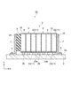
- FIG. 3 is a cross-sectional view schematically showing a state in which the battery module is fixed to the housing in the battery pack as the power storage device pack according to the first embodiment of the present invention.
- FIG. 6 is a cross-sectional view schematically showing a state where a battery module is fixed to a housing in a battery pack as a power storage device pack according to a second embodiment of the present invention.
- FIG. 1 is a perspective view showing a battery pack as a power storage device pack according to an embodiment of the present invention.
- a battery pack 1 (power storage device pack) of this embodiment includes a rectangular box-shaped housing 2 and a plurality (four in this case) of battery modules 3 (power storage devices) housed in the housing 2.
- the battery module 3 is fixed to the inner wall surface 2a of the housing 2 by a plurality of bolts 4 (see FIG. 4).
- casing 2 is formed with the metal (for example, iron).
- FIG. 2 is a perspective view showing the external appearance of the battery module 3.
- the battery module 3 includes a battery unit group 6 composed of a plurality (seven in this case) of battery units 5 arranged in one direction (X-axis direction), and arranged on both sides of the battery unit group 6. And a pair of end plates 7 and an elastic member 8 disposed between one end plate 7 and the battery unit 5 located at one end of the battery unit group 6.
- the battery unit 5 includes a secondary battery 9 that is a power storage device, a cell holder 10 that holds the secondary battery, and an L-shaped transmission disposed so as to be in contact with the secondary battery 9. And a heat plate 11.
- the secondary battery 9 is a lithium ion secondary battery in which an electrode assembly (not shown) is accommodated in a rectangular parallelepiped case 12, for example.
- the electrode assembly has a structure in which a plurality of positive electrode sheets and a plurality of negative electrode sheets are alternately stacked via separators.
- a positive terminal 13 and a negative terminal 14 are attached to the upper portion of the case 12 via an insulating ring 15.
- the positive electrode terminal 13 is electrically connected to the positive electrode sheet.
- the negative electrode terminal 14 is electrically connected to the negative electrode sheet.
- the case 12 is filled with an electrolytic solution (not shown).
- the secondary battery 9 has a pair of main surfaces 9a and a pair of side surfaces 9b.
- the main surface 9 a is a surface orthogonal to the X-axis direction in the secondary battery 9.
- the side surface 9 b is a surface orthogonal to the Y-axis direction in the secondary battery 9.
- the cell holder 10 is a frame-like member that is integrally formed of resin.
- the cell holder 10 has a bottom wall portion 16 on which the secondary battery 9 is placed, and a pair of side wall portions that are erected from both ends of the bottom wall portion 16 and sandwich the secondary battery 9 in the width direction (Y-axis direction). 17 and a connecting portion 18 that connects the side wall portions 17 to each other.
- a space surrounded by the bottom wall portion 16, the side wall portion 17, and the connecting portion 18 defines an accommodation region S in which the secondary battery 9 is accommodated.
- Bolt guide portions 20 each having a through hole 20a through which a shaft portion of a bolt 24 (see FIG. 2), which will be described later, passes are provided in the upper portion of the connecting portion 18 on the inner side in the width direction of the terminal accommodating portion 19.
- Bolt guide portions 21 having through holes 21 a through which the shaft portions of the bolts 24 are respectively provided at lower portions of both end portions of the bottom wall portion 16.
- the heat transfer plate 11 includes a main body 22 that contacts the main surface 9 a of the secondary battery 9, and an arrangement direction of the secondary batteries 9 from one end in the longitudinal direction of the main body 22 ( And a heat transfer portion 23 bent toward the elastic member 8 in the X-axis direction).
- the heat transfer unit 23 covers the outer surface 17 a (the surface on the side opposite to the accommodation region S) of the one side wall portion 17 of the cell holder 10.
- the heat transfer part 23 has a heat transfer surface 23a.
- the heat transfer surface 23 a is a surface that faces the inner wall surface 2 a when the battery module 3 is fixed to the inner wall surface 2 a of the housing 2.
- the end plate 7 cooperates with a plurality of sets (here, four sets) of bolts 24 and nuts 25 to restrain the plurality of secondary batteries 9 from both sides in the arrangement direction of the secondary batteries 9. It is a letter-shaped restraining member.
- the end plate 7 is made of a highly rigid metal (for example, iron).
- the end plate 7 is provided with a plurality of insertion holes 7a through which shaft portions of bolts 4 (see FIG. 4) for fixing the battery module 3 to the housing 2 pass.
- Two sets of bolts 24 and nuts 25 are arranged in the vertical direction (Z-axis direction) of the battery module 3.
- the elastic member 8 is a flat rubber that is disposed between the end plate 7 and the secondary battery 9 and absorbs the expansion of the secondary battery 9.
- FIG. 4 is a cross-sectional view schematically showing a state in which the battery module 3 is fixed to the housing 2 in the battery pack 1 as the power storage device pack according to the first embodiment of the present invention.
- 4A shows a state before the secondary battery 9 expands
- FIG. 4B shows a state where the secondary battery 9 expands.
- a plurality of heat conducting members 26 and a plurality of slip sheets 27 are respectively disposed between the heat transfer plates 11 (heat transfer surfaces 23 a) of the plurality of battery units 5 and the housing 2. .
- the heat conducting member 26 and the slip sheet 27 are arranged for each heat transfer plate 11.
- Each slip sheet 27 is disposed between each heat conducting member 26 and the housing 2.
- the heat conducting member 26 is a member that conducts heat from the heat transfer plate 11 to the housing 2 and is referred to as TIM (Thermal Interface Material).
- the heat conducting member 26 is formed of an adhesive material. Examples of the material having adhesiveness include silicon, acrylic, and urethane.
- Each of the plurality of heat conducting members 26 is disposed on the plurality of heat transfer surfaces 23a.
- One end of the heat conducting member 26 is joined to the slip sheet 27, and the other end of the heat conducting member 26 is joined to the heat transfer surface 23 a of the heat transfer portion 23 of the heat transfer plate 11. Specifically, the other end of the heat conducting member 26 is joined to the base end side (main body part 22 side) of the heat transfer unit 23 with respect to the center of the heat transfer unit 23 in the X-axis direction.
- the slip sheet 27 is a sliding member that can slide relative to the housing 2 in the arrangement direction of the secondary batteries 9.
- the slip sheet 27 is formed of a resin material having thermal conductivity and a low coefficient of friction, such as polyethylene terephthalate (PET).
- PET polyethylene terephthalate
- the slip sheet may contain a heat conductive filler.
- the width (length in the X-axis direction) of the slip sheet 27 is equal to or greater than (same as or larger than) the width (length in the X-axis direction) of the heat conducting member 26. In FIG. 4, the width of the slip sheet 27 is larger than the width of the heat conducting member 26.
- the battery module 3 is first assembled. Then, one end of each of the plurality of heat conducting members 26 is joined to each of the plurality of slip sheets 27, and the other end of each of the plurality of heat conducting members 26 is joined to the heat transfer section 23 (heat transfer surface) of each heat transfer plate 11 in the battery module 3. 23a). At this time, in order to allow the positional deviation of each battery unit 5 in the width direction (Y-axis direction), the initial length (length in the Y-axis direction) of each heat conducting member 26 is formed larger. Further, the initial width (length in the X-axis direction) of each heat conductive member 26 is narrowed so that the heat conductive member 26 does not protrude from the slip sheet 27 even if the heat conductive member 26 is crushed.
- the battery module 3 is arranged at a predetermined mounting position so that each slip sheet 27 contacts the inner wall surface 2 a of the housing 2, and the battery module 3 is fixed to the housing 2 with the bolt 4 in this state.
- the heat conducting member 26 is crushed, so that the heat conducting member 26 and the heat transfer plate 11 and the slip sheet 27 are sufficiently in close contact with each other.
- the heat conductive member 26 is crushed, the width of the heat conductive member 26 is widened, but the heat conductive member 26 does not protrude from the slip sheet 27.
- FIG. 5 is a cross-sectional view schematically showing a state in which the battery module 3 is fixed to the housing 2 in a battery pack as a comparative example.
- a battery pack 50 as a comparative example does not include the slip sheet 27 described above. That is, the heat conducting member 26 is joined to the housing 2 (inner wall surface 2a). In such a configuration, the following problems occur.
- a plurality of slip sheets 27 slidable in the arrangement direction of the secondary batteries 9 between the plurality of heat transfer plates 11 (heat transfer surfaces 23 a) and the housing 2.
- the plurality of slip sheets 27 are respectively joined to one ends of the plurality of heat conducting members 26. Accordingly, when the secondary battery 9 expands due to deterioration or charging / discharging of the secondary battery 9, the slip sheet 27 slides relatively in the arrangement direction of the secondary batteries 9, so that the heat conducting member joined to the slip sheet 27 It is possible to prevent a load in the shearing direction from being applied to 26.
- the plurality of slip sheets 27 are respectively disposed between the plurality of heat conducting members 26 and the housing 2. For this reason, when the secondary battery 9 expands, the slip sheet 27 slides relative to the housing 2 in the arrangement direction of the secondary batteries 9. Accordingly, the relative position between the heat transfer plate 11 and the heat conducting member 26 is always constant, so that the heat dissipation with respect to the housing 2 is stabilized.
- the heat generated in the secondary battery 9 is transmitted from the main body portion 22 to the heat transfer portion 23 in the heat transfer plate 11.
- the heat conducting member 26 is offset and joined to the proximal end side of the heat transfer portion 23, the heat dissipation performance with respect to the housing 2 can be further improved.
- the width of the slip sheet 27 is equal to or greater than the width of the heat conducting member 26, and therefore, when the battery module 3 is fixed to the housing 2, the heat conducting member 26 is crushed by the collapse of the heat conducting member 26. Is prevented from adhering to the housing 2. Accordingly, the slip sheet 27 can slide relatively smoothly with respect to the housing 2 in the arrangement direction of the secondary batteries 9.
- FIG. 6 is a cross-sectional view schematically showing a state in which the battery module 3 is fixed to the housing 2 in the battery pack 1 as the power storage device pack according to the second embodiment of the present invention.
- 6A shows a state before the secondary battery 9 expands
- FIG. 6B shows a state where the secondary battery 9 expands.
- Each slip sheet 27 is disposed between each heat transfer plate 11 and each heat conducting member 26. One end of the heat conducting member 26 is joined to the slip sheet 27, and the other end of the heat conducting member 26 is joined to the housing 2. A slip sheet 27 is in contact with the heat transfer portion 23 (heat transfer surface 23 a) of the heat transfer plate 11. The slip sheet 27 is in contact with the central portion of the heat transfer section 23 in the X-axis direction. The width of the slip sheet 27 is equal to or greater than the width of the heat conducting member 26.
- each of the plurality of heat conducting members 26 is joined to each of the plurality of slip sheets 27, and the other end of the plurality of heat conducting members 26 is joined. Bonded to the housing 2 (inner wall surface 2a). Then, the battery module 3 is arranged at a predetermined mounting position so that each heat transfer plate 11 is in contact with each slip sheet 27, and the battery module 3 is fixed to the housing 2 with the bolt 4 in this state. Then, the heat conducting member 26 is crushed, so that the heat conducting member 26, the slip sheet 27, and the housing 2 are sufficiently in close contact with each other.
- a plurality of slip sheets 27 slidable in the arrangement direction of the secondary batteries 9 are disposed between the plurality of heat transfer plates 11 (heat transfer surfaces 23 a) and the housing 2.
- the plurality of slip sheets 27 are respectively joined to one ends of the plurality of heat conducting members 26. Accordingly, when the secondary battery 9 expands due to deterioration or charging / discharging of the secondary battery 9, the slip sheet 27 slides relatively in the arrangement direction of the secondary batteries 9, so that the heat conducting member joined to the slip sheet 27 It is possible to prevent a load in the shearing direction from being applied to 26.
- the plurality of slip sheets 27 are disposed between the plurality of heat transfer plates 11 (heat transfer surfaces 23a) and the plurality of heat conduction members 26, respectively.
- the battery pack 1 when the battery pack 1 is manufactured, one end of each heat conducting member 26 is joined to each slip sheet 27 and the other end of each heat conducting member 26 is joined to the housing 2. Accordingly, when the battery module 3 is subsequently fixed to the housing 2, the heat conducting member 26 and the slip sheet 27 are not easily dropped.
- the thermal conductivity on the base end side of the heat transfer portion 23 is the tip end side (heat transfer portion 23 of the heat transfer portion 23. It is better than the thermal conductivity of the opposite side of the main body portion 22).
- the heat transfer portion 23 is bent from one end of the main body portion 22 toward the elastic member 8 in the arrangement direction of the secondary batteries 9.
- the width of the slip sheet 27 is equal to or greater than the width of the heat conducting member 26, and therefore, when the battery module 3 is fixed to the housing 2, the heat conducting member 26 is crushed by the collapse of the heat conducting member 26. Is prevented from adhering to the heat transfer plate 11. Therefore, the slip sheet 27 can slide relatively smoothly in the arrangement direction of the secondary batteries 9 with respect to the heat transfer plate 11.
- the present invention is not limited to the above embodiment.
- the other end of the heat conductive member 26 is offset and joined to the base end side of the heat-transfer part 23 of the heat-transfer plate 11, it is not restricted to the form in particular.
- the other end of the heat conducting member 26 may be joined to the central portion of the heat transfer portion 23 in the X-axis direction.
- the slip sheet 27 is contacting the center part in the X-axis direction of the heat-transfer part 23 of the heat-transfer plate 11, it is not restricted to the form in particular.
- the slip sheet 27 may be in contact with the tip end side of the heat transfer section 23 while being offset.
- the heat transfer portion 23 is bent from one end of the main body portion 22 toward the elastic member 8 in the arrangement direction of the secondary batteries 9. I can't.
- the heat transfer part 23 may be bent from one end of the main body part 22 toward the opposite side of the elastic member 8 in the arrangement direction of the secondary batteries 9.
- the battery module 3 only needs to include a plurality of heat transfer surfaces for thermally connecting each of the plurality of secondary batteries 9 and the inner wall surface 2a of the housing 2.
- the battery unit 5 may not include the heat transfer plate 11, and the heat conducting member 26 and the slip sheet 27 may be provided between the outer surface 17 a of the side wall portion 17 of the cell holder 10 and the inner wall surface 2 a of the housing 2. It may be provided.
- the other end of the heat conducting member 26 may be joined to the outer surface 17 a of the side wall portion 17 of the cell holder 10.
- the slip sheet 27 may be provided on the outer surface 17 a of the side wall portion 17 of the cell holder 10. In these cases, the outer surface 17a of the side wall portion 17 of the cell holder 10 functions as a heat transfer surface.
- the heat conducting member 26 and the slip sheet 27 may be provided between the side surface 9 b of the secondary battery 9 and the inner wall surface 2 a of the housing 2.
- the other end of the heat conducting member 26 may be joined to the side surface 9 b of the secondary battery 9.
- the slip sheet 27 may be provided directly on the side surface 9 b of the secondary battery 9. In these cases, the side surface 9b of the secondary battery 9 functions as a heat transfer surface.
- the said embodiment is the battery pack 1 provided with the battery module 3 which has secondary batteries 9, such as a lithium ion secondary battery
- this invention is not restricted to a secondary battery in particular,
- the present invention is also applicable to a power storage device pack including a power storage device module having a power storage device such as a capacitor or a lithium ion capacitor.
- SYMBOLS 1 Battery pack (electric storage device pack), 2 ... Housing, 3 ... Battery module (electric storage device module), 7 ... End plate (restraint member), 8 ... Elastic member, 9 ... Secondary battery (electric storage device), 9a DESCRIPTION OF SYMBOLS ... Main surface, 11 ... Heat-transfer plate, 22 ... Main-body part, 23 ... Heat-transfer part, 26 ... Heat conduction member, 27 ... Slip sheet (sliding member).
Landscapes
- Engineering & Computer Science (AREA)
- Chemical & Material Sciences (AREA)
- Chemical Kinetics & Catalysis (AREA)
- Electrochemistry (AREA)
- General Chemical & Material Sciences (AREA)
- Power Engineering (AREA)
- Manufacturing & Machinery (AREA)
- Microelectronics & Electronic Packaging (AREA)
- Secondary Cells (AREA)
- Battery Mounting, Suspending (AREA)
- Electric Double-Layer Capacitors Or The Like (AREA)
Abstract
電池パック1は、筐体2と、筐体2に固定された電池モジュール3とを備えている。電池モジュール3は、一方向に配列された複数の二次電池9と、複数の二次電池9を二次電池9の配列方向の両側から拘束する1対のエンドプレート7と、エンドプレート7と二次電池9との間に配置され、二次電池9の膨張を吸収する弾性部材8と、複数の二次電池9とそれぞれ接触するように配置された複数の伝熱プレート11とを有し、複数の伝熱プレート11と筐体2との間には、複数の伝熱プレート11から筐体2にそれぞれ熱を伝える複数の熱伝導部材26と、複数の熱伝導部材26の一端とそれぞれ接合され、二次電池9の配列方向に相対的に摺動可能な複数のスリップシート27とが配置されている。
Description
本発明の一態様は、蓄電装置パックに関する。
蓄電装置パックとしては、例えば特許文献1に記載されている電池パックが知られている。特許文献1に記載の電池パックは、複数の積層型電池セルと、各積層型電池セルに積層された複数の位置決めプレートと、複数の積層型電池セル及び複数の位置決めプレートを積層方向に付勢する付勢部と、複数の積層型電池セル、複数の位置決めプレート及び付勢部を格納する筐体とを備えている。位置決めプレートの折り曲げ部(放熱部)は、熱伝導シートを挟んで筐体に対して押し付けられている。
しかしながら、上記従来技術においては、以下の問題点が存在する。即ち、積層型電池セルの劣化または充放電によって、積層型電池セルは付勢部側に膨張する。ところで、熱伝導シートは、位置決めプレートの放熱部及び筐体にそれぞれ接合されている。従って、積層型電池セルが膨張すると、位置決めプレートも一緒に移動するので、熱伝導シートにせん断方向の荷重が加わる。このため、位置決めプレートと熱伝導シートとの界面剥離または熱伝導シートと筐体との界面剥離が発生したり、熱伝導シートの破断が発生する。その結果、位置決めプレートの放熱部から筐体に熱が伝わりにくくなり、筐体に対する放熱性が悪化する。
本発明の一態様は、筐体に対する放熱性を向上させることができる蓄電装置パックを提供する。
本発明の一態様に係る蓄電装置パックは、筐体と、筐体に固定された蓄電装置モジュールとを備え、蓄電装置モジュールは、一方向に配列された複数の蓄電装置と、複数の蓄電装置を一方向の両側から拘束する1対の拘束部材と、拘束部材と蓄電装置との間に配置され、蓄電装置の膨張を吸収する弾性部材と、複数の蓄電装置とそれぞれ接触するように配置された複数の伝熱プレートとを有する。複数の伝熱プレートと筐体との間には、複数の伝熱プレートから筐体にそれぞれ熱を伝える複数の熱伝導部材と、複数の熱伝導部材の一端とそれぞれ接合され、一方向に相対的に摺動可能な複数の摺動部材とが配置されている。
このような蓄電装置パックにおいては、蓄電装置において発生した熱は伝熱プレート及び熱伝導部材を通って筐体に放散される。ここで、複数の伝熱プレートと筐体との間には、一方向(蓄電装置の配列方向)に相対的に摺動可能な複数の摺動部材が配置されている。従って、蓄電装置の劣化または充放電によって蓄電装置が膨張すると、摺動部材が一方向に相対的に摺動するので、摺動部材と接合された熱伝導部材にせん断方向の荷重が加わることが防止される。このため、伝熱プレートと熱伝導部材との界面剥離または熱伝導部材と筐体との界面剥離、及び熱伝導部材の破断が防止される。これにより、筐体に対する放熱性を向上させることができる。
摺動部材は、熱伝導部材と筐体との間に配置されてもよく、筐体に対して一方向に相対的に摺動可能であってもよい。この場合には、蓄電装置が膨張すると、摺動部材が筐体に対して一方向に相対的に摺動する。従って、伝熱プレートと熱伝導部材との相対位置が常に一定となるので、筐体に対する放熱性が安定化する。
伝熱プレートは、蓄電装置の主面に接触する本体部と、本体部の一端から一方向に屈曲した伝熱部とを有してもよい。伝熱部には、熱伝導部材の他端が接合されていてもよく、熱伝導部材の他端は、伝熱部の本体部側に片寄って接合されていてもよい。蓄電装置において発生した熱は、伝熱プレートにおいて本体部から伝熱部に伝わる。このため、伝熱部の本体部側の熱伝導性は、伝熱部における本体部の反対側の熱伝導性よりも良い。そこで、熱伝導部材の他端を伝熱部の本体部側に片寄って接合することにより、筐体に対する放熱性を更に向上させることができる。
摺動部材は、伝熱プレートと熱伝導部材との間に配置されてもよく、伝熱プレートに対して一方向に相対的に摺動可能であってもよい。この場合、蓄電装置パックを製造するときは、各熱伝導部材の一端を各摺動部材にそれぞれ接合すると共に、各熱伝導部材の他端を筐体にそれぞれ接合する。従って、その後で蓄電装置モジュールを筐体に固定する際に、熱伝導部材及び摺動部材が落ちにくい。
伝熱プレートは、蓄電装置の主面に接触する本体部と、本体部の一端から一方向に弾性部材に向けて屈曲した伝熱部とを有してもよい。伝熱部には、摺動部材が接触していてもよく、熱伝導部材の他端は、筐体に接合されていてもよい。蓄電装置において発生した熱は、伝熱プレートにおいて本体部から伝熱部に伝わる。このため、伝熱部の本体部側の熱伝導性は、伝熱部における本体部の反対側の熱伝導性よりも良い。そこで、伝熱プレートにおいて、伝熱部を本体部の一端から一方向に弾性部材に向けて屈曲させることにより、蓄電装置が膨張したときは、摺動部材が伝熱プレートの伝熱部に対して本体部の反対側(弾性部材側)から本体部側に相対的に摺動するので、熱伝導部材が弾性部材側から本体部側に移動することになる。これにより、筐体に対する放熱性を更に向上させることができる。
本発明の一態様に係る蓄電装置パックは、筐体と、筐体に固定された蓄電装置モジュールとを備え、蓄電装置モジュールは、一方向に配列された複数の蓄電装置と、複数の蓄電装置を一方向の両側から拘束する1対の拘束部材と、拘束部材と蓄電装置との間に配置され、蓄電装置の膨張を吸収する弾性部材と、複数の蓄電装置のそれぞれと筐体とを熱的に接続するための複数の伝熱面と、を有する。複数の伝熱面と筐体との間には、複数の伝熱面から筐体にそれぞれ熱を伝える複数の熱伝導部材と、複数の熱伝導部材の一端とそれぞれ接合され、一方向に相対的に摺動可能な複数の摺動部材とが配置されている。
このような蓄電装置パックにおいては、蓄電装置において発生した熱は伝熱面から熱伝導部材を通って筐体に放散される。ここで、複数の伝熱面と筐体との間には、一方向に相対的に摺動可能な複数の摺動部材が配置されている。従って、蓄電装置の劣化または充放電によって蓄電装置が膨張すると、摺動部材が一方向に相対的に摺動するので、摺動部材と接合された熱伝導部材にせん断方向の荷重が加わることが防止される。このため、伝熱面と熱伝導部材との界面剥離または熱伝導部材と筐体との界面剥離、及び熱伝導部材の破断が防止される。これにより、筐体に対する放熱性を向上させることができる。
摺動部材は、熱伝導部材と筐体との間に配置されてもよく、筐体に対して一方向に相対的に摺動可能であってもよい。この場合には、蓄電装置が膨張すると、摺動部材が筐体に対して一方向に相対的に摺動する。従って、伝熱面と熱伝導部材との相対位置が常に一定となるので、筐体に対する放熱性が安定化する。
摺動部材は、伝熱面と熱伝導部材との間に配置されてもよく、伝熱面に対して一方向に相対的に摺動可能であってもよい。この場合、蓄電装置パックを製造するときは、各熱伝導部材の一端を各摺動部材にそれぞれ接合すると共に、各熱伝導部材の他端を筐体にそれぞれ接合する。従って、その後で蓄電装置モジュールを筐体に固定する際に、熱伝導部材及び摺動部材が落ちにくい。
蓄電装置モジュールは、複数の蓄電装置とそれぞれ接触するように配置された複数の伝熱プレートとをさらに有してもよい。伝熱プレートは、蓄電装置の主面に接触する本体部と、本体部の一端から一方向に屈曲した伝熱部とを有してもよい。伝熱部は、伝熱面を含んでもよい。この場合、蓄電装置において発生した熱は、伝熱プレートに伝わり、熱伝導部材及び摺動部材を介して筐体に放散される。
摺動部材の幅は、熱伝導部材の幅以上であってもよい。この場合には、蓄電装置モジュールを筐体に固定する際に、熱伝導部材の潰れによって熱伝導部材が筐体または伝熱プレート若しくは伝熱面に付着することが防止される。従って、摺動部材が一方向に相対的にスムーズに摺動可能となる。
本発明の一態様によれば、筐体に対する放熱性を向上させることができる蓄電装置パックが提供される。
以下、本発明の実施形態について、図面を参照して詳細に説明する。なお、図面において、同一または同等の要素には同じ符号を付し、重複する説明を省略する。
図1は、本発明の一実施形態に係る蓄電装置パックとして電池パックを示す斜視図である。図1において、本実施形態の電池パック1(蓄電装置パック)は、矩形箱状の筐体2と、この筐体2内に収容された複数(ここでは4つ)の電池モジュール3(蓄電装置モジュール)とを備えている。電池モジュール3は、複数のボルト4(図4参照)により筐体2の内壁面2aに固定されている。筐体2は、金属(例えば鉄)で形成されている。
図2は、電池モジュール3の外観を示す斜視図である。図2において、電池モジュール3は、一方向(X軸方向)に配列された複数(ここでは7つ)の電池ユニット5から構成される電池ユニット群6と、この電池ユニット群6の両側に配置された1対のエンドプレート7と、一方のエンドプレート7と電池ユニット群6の一端に位置する電池ユニット5との間に配置された弾性部材8とを有している。
電池ユニット5は、図3に示されるように、蓄電装置である二次電池9と、この二次電池を保持するセルホルダ10と、二次電池9と接触するように配置されたL字形の伝熱プレート11とを有している。
二次電池9は、例えば直方体状のケース12内に電極組立体(図示せず)が収容されてなるリチウムイオン二次電池である。電極組立体は、複数の正極シートと複数の負極シートとがセパレータを介して交互に積層された構造を有している。ケース12の上部には、正極端子13及び負極端子14が絶縁リング15を介して取り付けられている。正極端子13は、正極シートと電気的に接続されている。負極端子14は、負極シートと電気的に接続されている。なお、ケース12内には、電解液(図示せず)が充填されている。二次電池9は、一対の主面9aと一対の側面9bとを有する。主面9aは、二次電池9におけるX軸方向と直交する面である。側面9bは、二次電池9におけるY軸方向と直交する面である。
セルホルダ10は、樹脂により一体成形された枠体状の部材である。セルホルダ10は、二次電池9が載置される底壁部16と、この底壁部16の両端から立設し、二次電池9を幅方向(Y軸方向)に挟む1対の側壁部17と、各側壁部17同士を連結する連結部18とを有している。底壁部16、側壁部17及び連結部18に囲まれる空間は、二次電池9が収容される収容領域Sを画成している。
連結部18の両端部の上部には、二次電池9の正極端子13及び負極端子14の一部を囲う端子収容部19がそれぞれ設けられている。連結部18における端子収容部19よりも幅方向内側の上部には、後述するボルト24(図2参照)の軸部が貫通する貫通孔20aを有するボルトガイド部20がそれぞれ設けられている。底壁部16の両端部の下部には、ボルト24の軸部が貫通する貫通孔21aを有するボルトガイド部21がそれぞれ設けられている。
伝熱プレート11は、図3及び図4に示されるように、二次電池9の主面9aに接触する本体部22と、この本体部22の長手方向一端から二次電池9の配列方向(X軸方向)に弾性部材8に向かって屈曲した伝熱部23とを有している。伝熱部23は、セルホルダ10の一方の側壁部17の外面17a(収容領域Sとは反対側の面)を覆っている。伝熱部23は、伝熱面23aを有する。伝熱面23aは、電池モジュール3が筐体2の内壁面2aに固定される際に、内壁面2aと対向する面である。
図2に戻り、エンドプレート7は、複数組(ここでは4組)のボルト24及びナット25と協働して、複数の二次電池9を二次電池9の配列方向の両側から拘束するL字形の拘束部材である。エンドプレート7は、剛性が高い金属(例えば鉄)で形成されている。エンドプレート7には、電池モジュール3を筐体2に固定するためのボルト4(図4参照)の軸部が通る複数の挿通孔7aが設けられている。ボルト24及びナット25は、電池モジュール3の上下方向(Z軸方向)に2組ずつ配置されている。弾性部材8は、エンドプレート7と二次電池9との間に配置され、二次電池9の膨張を吸収する平板状のゴムである。
図4は、本発明の第1実施形態に係る蓄電装置パックとしての電池パック1において、電池モジュール3が筐体2に固定された状態を概略的に示す断面図である。なお、図4(a)は、二次電池9が膨張する前の状態を示し、図4(b)は、二次電池9が膨張している状態を示している。
図4において、複数の電池ユニット5の伝熱プレート11(伝熱面23a)と筐体2との間には、複数の熱伝導部材26と、複数のスリップシート27とがそれぞれ配置されている。熱伝導部材26及びスリップシート27は、伝熱プレート11毎に配置されている。各スリップシート27は、各熱伝導部材26と筐体2との間にそれぞれ配置されている。
熱伝導部材26は、伝熱プレート11から筐体2に熱を伝える部材であり、TIM(Thermal Interface Material)と称される。熱伝導部材26は、粘着性を有する材料で形成されている。粘着性を有する材料としては、シリコン、アクリルまたはウレタン等が挙げられる。複数の熱伝導部材26のそれぞれは、複数の伝熱面23a上に配置される。
熱伝導部材26の一端はスリップシート27と接合され、熱伝導部材26の他端は伝熱プレート11の伝熱部23の伝熱面23aと接合されている。具体的には、熱伝導部材26の他端は、伝熱部23のX軸方向における中心に対して伝熱部23の基端側(本体部22側)に片寄って接合されている。
スリップシート27は、筐体2に対して二次電池9の配列方向に相対的に摺動可能な摺動部材である。スリップシート27は、熱伝導性を有し且つ摩擦係数が低い樹脂材料、例えばポリエチレンテレフタレート(PET)等で形成されている。なお、スリップシートには、熱伝導性フィラーが含まれていてもよい。スリップシート27の幅(X軸方向における長さ)は、熱伝導部材26の幅(X軸方向における長さ)と同等以上(同一かそれよりも大きい)である。図4では、スリップシート27の幅は、熱伝導部材26の幅よりも大きくなっている。
以上のような電池パック1を製造するときは、まず電池モジュール3を組み立てる。そして、複数の熱伝導部材26の一端を複数のスリップシート27にそれぞれ接合すると共に、複数の熱伝導部材26の他端を電池モジュール3における各伝熱プレート11の伝熱部23(伝熱面23a)にそれぞれ接合する。このとき、各電池ユニット5の幅方向(Y軸方向)の位置ずれを許容するために、各熱伝導部材26の初期長さ(Y軸方向における長さ)を大きめに形成しておく。また、熱伝導部材26が潰れてもスリップシート27からはみ出ないように、各熱伝導部材26の初期幅(X軸方向における長さ)を狭めに形成しておく。
そして、各スリップシート27が筐体2の内壁面2aに接触するように、電池モジュール3を所定の取付位置に配置し、その状態でボルト4により電池モジュール3を筐体2に固定する。すると、熱伝導部材26が潰れることで、熱伝導部材26と伝熱プレート11及びスリップシート27とが十分に密着した状態となる。また、熱伝導部材26が潰れることで、熱伝導部材26の幅が広がるが、熱伝導部材26がスリップシート27からはみ出ることはない。
このような電池パック1において、二次電池9が劣化すると、二次電池9から熱が発生しやすくなる。二次電池9において発生した熱は、伝熱プレート11、熱伝導部材26及びスリップシート27を通って筐体2に放散される。一方で、二次電池9の劣化時及び充放電時には、図4(b)に示されるように、二次電池9が弾性部材8側に膨張する。このとき、熱伝導部材26と伝熱プレート11及びスリップシート27とは密着しているが、スリップシート27と筐体2とは相対的に摺動可能である。このため、電池ユニット5、熱伝導部材26及びスリップシート27は、筐体2に対して弾性部材8側に一体で移動する。
図5は、比較例としての電池パックにおいて、電池モジュール3が筐体2に固定された状態を概略的に示す断面図である。図5において、比較例としての電池パック50は、上記のスリップシート27を備えていない。つまり、熱伝導部材26は筐体2(内壁面2a)に接合されている。このような構成では、以下の不具合が発生する。
即ち、二次電池9の劣化または充放電によって、二次電池9が弾性部材8側に膨張すると、熱伝導部材26にせん断方向の荷重が加わる。このため、伝熱プレート11と熱伝導部材26との界面剥離または熱伝導部材26と筐体2との界面剥離が発生したり、熱伝導部材26の破断が発生しやすくなる。その結果、伝熱プレート11から筐体2に熱が伝わりにくくなるので、筐体2に対する放熱性が悪化する。
ところで、電池ユニット5の配列方向に延びる1つのスリップシートを使用した場合には、二次電池9が弾性部材8側に膨張したときに、スリップシートが筐体2に対して多少ずれるが、熱伝導部材26とスリップシートとの界面における各熱伝導部材26のピッチは、二次電池9の膨張前と変わらない。従って、この場合にも、熱伝導部材26にせん断方向の荷重が加わるので、比較例と同様に、筐体2に対する放熱性が悪化する。
これに対し本実施形態では、複数の伝熱プレート11(伝熱面23a)と筐体2との間には、二次電池9の配列方向に相対的に摺動可能な複数のスリップシート27が配置されている。複数のスリップシート27は、複数の熱伝導部材26の一端とそれぞれ接合されている。従って、二次電池9の劣化または充放電によって二次電池9が膨張すると、スリップシート27が二次電池9の配列方向に相対的に摺動するので、スリップシート27と接合された熱伝導部材26にせん断方向の荷重が加わることが防止される。このため、伝熱プレート11と熱伝導部材26との界面剥離または熱伝導部材26と筐体2との界面剥離、及び熱伝導部材26の破断が防止される。これにより、伝熱プレート11から筐体2に熱が確実に伝わるので、筐体2に対する放熱性を向上させることができる。
また、本実施形態では、複数のスリップシート27は、複数の熱伝導部材26と筐体2との間にそれぞれ配置されている。このため、二次電池9が膨張すると、スリップシート27が筐体2に対して二次電池9の配列方向に相対的に摺動する。従って、伝熱プレート11と熱伝導部材26との相対位置は常に一定となるので、筐体2に対する放熱性が安定化する。
また、二次電池9において発生した熱は、伝熱プレート11において本体部22から伝熱部23に伝わる。このため、伝熱部23の先端よりも基端に近いほど、筐体2までの放熱経路が短くなる。従って、伝熱部23の基端側(伝熱部23の本体部22側)の熱伝導性は、伝熱部23の先端側(伝熱部23における本体部22の反対側)の熱伝導性よりも良い。本実施形態では、熱伝導部材26は伝熱部23の基端側に片寄って接合されているので、筐体2に対する放熱性を更に向上させることができる。
また、本実施形態では、スリップシート27の幅は熱伝導部材26の幅と同等以上であるので、電池モジュール3を筐体2に固定する際に、熱伝導部材26の潰れによって熱伝導部材26が筐体2に付着することが防止される。従って、スリップシート27が筐体2に対して二次電池9の配列方向に相対的にスムーズに摺動可能となる。
図6は、本発明の第2実施形態に係る蓄電装置パックとしての電池パック1において、電池モジュール3が筐体2に固定された状態を概略的に示す断面図である。なお、図6(a)は、二次電池9が膨張する前の状態を示し、図6(b)は、二次電池9が膨張している状態を示している。
図6において、電池モジュール3における複数の伝熱プレート11(伝熱面23a)と筐体2との間には、上記第1実施形態と同様に、複数の熱伝導部材26と複数のスリップシート27とが配置されている。
各スリップシート27は、各伝熱プレート11と各熱伝導部材26との間にそれぞれ配置されている。熱伝導部材26の一端はスリップシート27と接合され、熱伝導部材26の他端は筐体2と接合されている。伝熱プレート11の伝熱部23(伝熱面23a)には、スリップシート27が接触している。スリップシート27は、伝熱部23のX軸方向における中央部に接触している。スリップシート27の幅は、熱伝導部材26の幅と同等以上である。
このような電池パック1を製造するときは、電池モジュール3を組み立てた後、複数の熱伝導部材26の一端を複数のスリップシート27にそれぞれ接合すると共に、複数の熱伝導部材26の他端を筐体2(内壁面2a)に接合する。そして、各伝熱プレート11が各スリップシート27と接触するように、電池モジュール3を所定の取付位置に配置し、その状態でボルト4により電池モジュール3を筐体2に固定する。すると、熱伝導部材26が潰れることで、熱伝導部材26とスリップシート27及び筐体2とが十分に密着した状態となる。
このような電池パック1において、二次電池9の劣化時及び充放電時には、図6(b)に示されるように、二次電池9が弾性部材8側に膨張する。このとき、熱伝導部材26とスリップシート27及び筐体2とは密着しているが、スリップシート27と伝熱プレート11とは相対的に摺動可能である。このため、電池ユニット5がスリップシート27に対して弾性部材8側に摺動する。言い換えると、スリップシート27が電池ユニット5に対して弾性部材8の反対側に相対的に摺動することとなる。
本実施形態においては、複数の伝熱プレート11(伝熱面23a)と筐体2との間には、二次電池9の配列方向に相対的に摺動可能な複数のスリップシート27が配置されている。複数のスリップシート27は、複数の熱伝導部材26の一端とそれぞれ接合されている。従って、二次電池9の劣化または充放電によって二次電池9が膨張すると、スリップシート27が二次電池9の配列方向に相対的に摺動するので、スリップシート27と接合された熱伝導部材26にせん断方向の荷重が加わることが防止される。このため、伝熱プレート11と熱伝導部材26との界面剥離または熱伝導部材26と筐体2との界面剥離、及び熱伝導部材26の破断が防止される。これにより、伝熱プレート11から筐体2に熱が確実に伝わるので、筐体2に対する放熱性を向上させることができる。
また、本実施形態では、複数のスリップシート27は、複数の伝熱プレート11(伝熱面23a)と複数の熱伝導部材26との間にそれぞれ配置されている。このような構成では、電池パック1を製造するときは、各熱伝導部材26の一端を各スリップシート27にそれぞれ接合すると共に、各熱伝導部材26の他端を筐体2にそれぞれ接合する。従って、その後で電池モジュール3を筐体2に固定する際に、熱伝導部材26及びスリップシート27が落ちにくい。
また、上述したように、伝熱プレート11において、伝熱部23の基端側(伝熱部23の本体部22側)の熱伝導性は、伝熱部23の先端側(伝熱部23における本体部22の反対側)の熱伝導性よりも良い。本実施形態では、伝熱プレート11において、伝熱部23が本体部22の一端から二次電池9の配列方向に弾性部材8に向けて屈曲している。このため、二次電池9が膨張したときは、スリップシート27が伝熱プレート11の伝熱部23に対して伝熱部23の先端側から基端側に相対的に摺動するので、熱伝導部材26が伝熱部23の先端側から基端側が移動することになる。これにより、筐体2に対する放熱性を更に向上させることができる。
また、本実施形態では、スリップシート27の幅は熱伝導部材26の幅と同等以上であるので、電池モジュール3を筐体2に固定する際に、熱伝導部材26の潰れによって熱伝導部材26が伝熱プレート11に付着することが防止される。従って、スリップシート27が伝熱プレート11に対して二次電池9の配列方向に相対的にスムーズに摺動可能となる。
なお、本発明は、上記実施形態には限定されない。例えば上記第1実施形態では、熱伝導部材26の他端が伝熱プレート11の伝熱部23の基端側に片寄って接合されているが、特にその形態には限られない。例えば熱伝導部材26の他端が伝熱部23のX軸方向における中央部に接合されていてもよい。
また、上記第2実施形態では、スリップシート27が伝熱プレート11の伝熱部23のX軸方向における中央部に接触しているが、特にその形態には限られない。例えばスリップシート27が伝熱部23の先端側に片寄って接触していてもよい。
また、上記実施形態では、伝熱プレート11において、伝熱部23が本体部22の一端から二次電池9の配列方向に弾性部材8に向けて屈曲しているが、特にその形態には限られない。伝熱部23が本体部22の一端から二次電池9の配列方向に弾性部材8の反対側に向けて屈曲していてもよい。
また、電池モジュール3は、複数の二次電池9のそれぞれと筐体2の内壁面2aとを熱的に接続するための複数の伝熱面を備えていればよい。例えば、電池ユニット5は、伝熱プレート11を備えていなくてもよく、熱伝導部材26及びスリップシート27は、セルホルダ10の側壁部17の外面17aと筐体2の内壁面2aとの間に設けられてもよい。例えば、上記第1実施形態において、熱伝導部材26の他端はセルホルダ10の側壁部17の外面17aに接合されてもよい。上記第2実施形態において、スリップシート27はセルホルダ10の側壁部17の外面17aに設けられてもよい。これらの場合、セルホルダ10の側壁部17の外面17aが伝熱面として機能する。
また、熱伝導部材26及びスリップシート27は、二次電池9の側面9bと筐体2の内壁面2aとの間に設けられてもよい。例えば、上記第1実施形態において、熱伝導部材26の他端は二次電池9の側面9bに接合されてもよい。上記第2実施形態において、スリップシート27は二次電池9の側面9bに直接設けられてもよい。これらの場合、二次電池9の側面9bが伝熱面として機能する。
さらに、上記実施形態は、リチウムイオン二次電池等の二次電池9を有する電池モジュール3を備えた電池パック1であるが、本発明は、特に二次電池には限られず、例えば電気二重層キャパシタまたはリチウムイオンキャパシタ等の蓄電装置を有する蓄電装置モジュールを備えた蓄電装置パックにも適用可能である。
1…電池パック(蓄電装置パック)、2…筐体、3…電池モジュール(蓄電装置モジュール)、7…エンドプレート(拘束部材)、8…弾性部材、9…二次電池(蓄電装置)、9a…主面、11…伝熱プレート、22…本体部、23…伝熱部、26…熱伝導部材、27…スリップシート(摺動部材)。
Claims (10)
- 筐体と、前記筐体に固定された蓄電装置モジュールとを備えた蓄電装置パックであって、
前記蓄電装置モジュールは、一方向に配列された複数の蓄電装置と、前記複数の蓄電装置を前記一方向の両側から拘束する1対の拘束部材と、前記拘束部材と前記蓄電装置との間に配置され、前記蓄電装置の膨張を吸収する弾性部材と、前記複数の蓄電装置とそれぞれ接触するように配置された複数の伝熱プレートとを有し、
前記複数の伝熱プレートと前記筐体との間には、前記複数の伝熱プレートから前記筐体にそれぞれ熱を伝える複数の熱伝導部材と、前記複数の熱伝導部材の一端とそれぞれ接合され、前記一方向に相対的に摺動可能な複数の摺動部材とが配置されている蓄電装置パック。 - 前記摺動部材は、前記熱伝導部材と前記筐体との間に配置され、前記筐体に対して前記一方向に相対的に摺動可能である請求項1記載の蓄電装置パック。
- 前記伝熱プレートは、前記蓄電装置の主面に接触する本体部と、前記本体部の一端から前記一方向に屈曲した伝熱部とを有し、
前記伝熱部には、前記熱伝導部材の他端が接合されており、
前記熱伝導部材の他端は、前記伝熱部の前記本体部側に片寄って接合されている請求項2記載の蓄電装置パック。 - 前記摺動部材は、前記伝熱プレートと前記熱伝導部材との間に配置され、前記伝熱プレートに対して前記一方向に相対的に摺動可能である請求項1記載の蓄電装置パック。
- 前記伝熱プレートは、前記蓄電装置の主面に接触する本体部と、前記本体部の一端から前記一方向に前記弾性部材に向けて屈曲した伝熱部とを有し、
前記伝熱部には、前記摺動部材が接触しており、
前記熱伝導部材の他端は、前記筐体に接合されている請求項4記載の蓄電装置パック。 - 筐体と、前記筐体に固定された蓄電装置モジュールとを備えた蓄電装置パックであって、
前記蓄電装置モジュールは、一方向に配列された複数の蓄電装置と、前記複数の蓄電装置を前記一方向の両側から拘束する1対の拘束部材と、前記拘束部材と前記蓄電装置との間に配置され、前記蓄電装置の膨張を吸収する弾性部材と、前記複数の蓄電装置のそれぞれと前記筐体とを熱的に接続するための複数の伝熱面と、を有し、
前記複数の伝熱面と前記筐体との間には、前記複数の伝熱面から前記筐体にそれぞれ熱を伝える複数の熱伝導部材と、前記複数の熱伝導部材の一端とそれぞれ接合され、前記一方向に相対的に摺動可能な複数の摺動部材とが配置されている蓄電装置パック。 - 前記摺動部材は、前記熱伝導部材と前記筐体との間に配置され、前記筐体に対して前記一方向に相対的に摺動可能である請求項6記載の蓄電装置パック。
- 前記摺動部材は、前記伝熱面と前記熱伝導部材との間に配置され、前記伝熱面に対して前記一方向に相対的に摺動可能である請求項6記載の蓄電装置パック。
- 前記蓄電装置モジュールは、前記複数の蓄電装置とそれぞれ接触するように配置された複数の伝熱プレートとをさらに有し、
前記伝熱プレートは、前記蓄電装置の主面に接触する本体部と、前記本体部の一端から前記一方向に屈曲した伝熱部とを有し、
前記伝熱部は、前記伝熱面を含む、請求項6~8のいずれか一項記載の蓄電装置パック。 - 前記摺動部材の幅は、前記熱伝導部材の幅以上である請求項1~9のいずれか一項記載の蓄電装置パック。
Priority Applications (4)
| Application Number | Priority Date | Filing Date | Title |
|---|---|---|---|
| US16/082,700 US20190097284A1 (en) | 2016-03-15 | 2016-12-06 | Power storage device pack |
| JP2018505249A JP6380704B2 (ja) | 2016-03-15 | 2016-12-06 | 蓄電装置パック |
| CN201680083462.1A CN108780933B (zh) | 2016-03-15 | 2016-12-06 | 蓄电装置包 |
| DE112016006606.6T DE112016006606B4 (de) | 2016-03-15 | 2016-12-06 | Leistungsspeichervorrichtungspack |
Applications Claiming Priority (2)
| Application Number | Priority Date | Filing Date | Title |
|---|---|---|---|
| JP2016-051162 | 2016-03-15 | ||
| JP2016051162 | 2016-03-15 |
Publications (1)
| Publication Number | Publication Date |
|---|---|
| WO2017158950A1 true WO2017158950A1 (ja) | 2017-09-21 |
Family
ID=59850775
Family Applications (1)
| Application Number | Title | Priority Date | Filing Date |
|---|---|---|---|
| PCT/JP2016/086229 Ceased WO2017158950A1 (ja) | 2016-03-15 | 2016-12-06 | 蓄電装置パック |
Country Status (5)
| Country | Link |
|---|---|
| US (1) | US20190097284A1 (ja) |
| JP (1) | JP6380704B2 (ja) |
| CN (1) | CN108780933B (ja) |
| DE (1) | DE112016006606B4 (ja) |
| WO (1) | WO2017158950A1 (ja) |
Cited By (9)
| Publication number | Priority date | Publication date | Assignee | Title |
|---|---|---|---|---|
| KR20200127749A (ko) * | 2019-05-03 | 2020-11-11 | 현대자동차주식회사 | 차량용 배터리 모듈 |
| JPWO2021024773A1 (ja) * | 2019-08-07 | 2021-02-11 | ||
| GB2590392A (en) * | 2019-12-16 | 2021-06-30 | Dyson Technology Ltd | A battery cell with internal swelling relief and external cooling features |
| US20220416328A1 (en) * | 2019-10-09 | 2022-12-29 | Sanyo Electric Co., Ltd. | Power supply device, electric vehicle using same, and power storage device |
| JP2023007351A (ja) * | 2021-06-30 | 2023-01-18 | 住友電気工業株式会社 | 蓄電システム固定用具、蓄電システム固定用具セット及び床面に接着された金属板を取り除く方法 |
| JP2023074361A (ja) * | 2021-11-17 | 2023-05-29 | プライムプラネットエナジー&ソリューションズ株式会社 | 電池モジュールおよびその製造方法 |
| EP4560785A1 (en) * | 2023-11-27 | 2025-05-28 | Samsung Sdi Co., Ltd. | Battery pack |
| JP2025516924A (ja) * | 2022-05-25 | 2025-05-30 | エルジー エナジー ソリューション リミテッド | 電池モジュール及びその製造方法 |
| US12374734B2 (en) | 2019-12-16 | 2025-07-29 | Dyson Technology Limited | Battery cell with internal swelling relief and external cooling features |
Families Citing this family (8)
| Publication number | Priority date | Publication date | Assignee | Title |
|---|---|---|---|---|
| JP7161672B2 (ja) * | 2018-11-12 | 2022-10-27 | トヨタ自動車株式会社 | 組電池 |
| CN113383452B (zh) * | 2019-02-12 | 2024-02-06 | 三洋电机株式会社 | 电池组件 |
| GB2589845A (en) | 2019-11-20 | 2021-06-16 | Hyperdrive Innovation Ltd | Method and apparatus |
| KR102907378B1 (ko) * | 2020-10-06 | 2025-12-31 | 주식회사 엘지에너지솔루션 | 배터리 모듈, 이를 포함하는 배터리 팩 및 자동차 |
| DE102021106414A1 (de) * | 2021-03-16 | 2022-09-22 | Bayerische Motoren Werke Aktiengesellschaft | Kondensatorsysteme mit verbesserten Anschlüssen und Herstellungsverfahren |
| EP4297151A4 (en) * | 2021-07-02 | 2024-09-11 | LG Energy Solution, Ltd. | COOLING FIN, BATTERY MODULE, BATTERY PACK AND DEVICE THEREOF |
| CN113506945B (zh) * | 2021-09-10 | 2021-11-19 | 中航锂电科技有限公司 | 一种电池包 |
| DE102022130845A1 (de) | 2022-11-22 | 2024-05-23 | Audi Aktiengesellschaft | Batteriemodul mit reduzierter Verschleißanfälligkeit und Verfahren zum Herstellen eines Batteriemoduls |
Citations (2)
| Publication number | Priority date | Publication date | Assignee | Title |
|---|---|---|---|---|
| JP2012248374A (ja) * | 2011-05-26 | 2012-12-13 | Hitachi Ltd | 電池モジュール |
| WO2016031628A1 (ja) * | 2014-08-27 | 2016-03-03 | 株式会社 豊田自動織機 | 電池パック |
Family Cites Families (12)
| Publication number | Priority date | Publication date | Assignee | Title |
|---|---|---|---|---|
| US20050026014A1 (en) * | 2003-07-31 | 2005-02-03 | Michael Fogaing | Polymer batteries having thermal exchange apparatus |
| US20080299452A1 (en) * | 2007-05-31 | 2008-12-04 | Densei-Lambda K.K. | Battery pack |
| KR101071537B1 (ko) * | 2009-09-17 | 2011-10-10 | 주식회사 엘지화학 | 신규한 구조의 방열부재를 포함하는 전지모듈 및 중대형 전지팩 |
| JP2011171029A (ja) * | 2010-02-17 | 2011-09-01 | Sanyo Electric Co Ltd | 電池モジュール |
| JP5580282B2 (ja) * | 2011-12-09 | 2014-08-27 | 本田技研工業株式会社 | バッテリの冷却装置 |
| JP5904113B2 (ja) * | 2012-12-10 | 2016-04-13 | 株式会社豊田自動織機 | 電池モジュール及び電池モジュールの製造方法 |
| JP2014175078A (ja) * | 2013-03-06 | 2014-09-22 | Captex Co Ltd | 電池パック |
| US10153526B2 (en) * | 2013-07-17 | 2018-12-11 | Calsonic Kansei Corporation | Assembled battery |
| JP5754497B2 (ja) * | 2013-12-04 | 2015-07-29 | 株式会社豊田自動織機 | 電池パック及び電池パックの製造方法 |
| US9296310B2 (en) * | 2014-03-18 | 2016-03-29 | Ford Global Technologies, Llc | Traction battery thermal management system |
| JP6237479B2 (ja) * | 2014-06-05 | 2017-11-29 | 株式会社豊田自動織機 | 電池モジュール及び電池パック |
| JP6589690B2 (ja) * | 2016-02-25 | 2019-10-16 | 株式会社豊田自動織機 | 電池パック |
-
2016
- 2016-12-06 DE DE112016006606.6T patent/DE112016006606B4/de not_active Expired - Fee Related
- 2016-12-06 CN CN201680083462.1A patent/CN108780933B/zh not_active Expired - Fee Related
- 2016-12-06 WO PCT/JP2016/086229 patent/WO2017158950A1/ja not_active Ceased
- 2016-12-06 US US16/082,700 patent/US20190097284A1/en not_active Abandoned
- 2016-12-06 JP JP2018505249A patent/JP6380704B2/ja not_active Expired - Fee Related
Patent Citations (2)
| Publication number | Priority date | Publication date | Assignee | Title |
|---|---|---|---|---|
| JP2012248374A (ja) * | 2011-05-26 | 2012-12-13 | Hitachi Ltd | 電池モジュール |
| WO2016031628A1 (ja) * | 2014-08-27 | 2016-03-03 | 株式会社 豊田自動織機 | 電池パック |
Cited By (14)
| Publication number | Priority date | Publication date | Assignee | Title |
|---|---|---|---|---|
| KR102776217B1 (ko) * | 2019-05-03 | 2025-03-04 | 현대자동차주식회사 | 차량용 배터리 모듈 |
| KR20200127749A (ko) * | 2019-05-03 | 2020-11-11 | 현대자동차주식회사 | 차량용 배터리 모듈 |
| JP7606967B2 (ja) | 2019-08-07 | 2024-12-26 | 三洋電機株式会社 | 電源装置及びこれを用いた電動車両並びに蓄電装置 |
| JPWO2021024773A1 (ja) * | 2019-08-07 | 2021-02-11 | ||
| US20220416328A1 (en) * | 2019-10-09 | 2022-12-29 | Sanyo Electric Co., Ltd. | Power supply device, electric vehicle using same, and power storage device |
| GB2590392B (en) * | 2019-12-16 | 2023-01-04 | Dyson Technology Ltd | A battery cell with internal swelling relief and external cooling features |
| GB2590392A (en) * | 2019-12-16 | 2021-06-30 | Dyson Technology Ltd | A battery cell with internal swelling relief and external cooling features |
| US12374734B2 (en) | 2019-12-16 | 2025-07-29 | Dyson Technology Limited | Battery cell with internal swelling relief and external cooling features |
| JP2023007351A (ja) * | 2021-06-30 | 2023-01-18 | 住友電気工業株式会社 | 蓄電システム固定用具、蓄電システム固定用具セット及び床面に接着された金属板を取り除く方法 |
| JP7757807B2 (ja) | 2021-06-30 | 2025-10-22 | 住友電気工業株式会社 | 蓄電システム固定用具、及び蓄電システム固定用具セット |
| JP2023074361A (ja) * | 2021-11-17 | 2023-05-29 | プライムプラネットエナジー&ソリューションズ株式会社 | 電池モジュールおよびその製造方法 |
| JP7478126B2 (ja) | 2021-11-17 | 2024-05-02 | プライムプラネットエナジー&ソリューションズ株式会社 | 電池モジュールおよびその製造方法 |
| JP2025516924A (ja) * | 2022-05-25 | 2025-05-30 | エルジー エナジー ソリューション リミテッド | 電池モジュール及びその製造方法 |
| EP4560785A1 (en) * | 2023-11-27 | 2025-05-28 | Samsung Sdi Co., Ltd. | Battery pack |
Also Published As
| Publication number | Publication date |
|---|---|
| JP6380704B2 (ja) | 2018-08-29 |
| CN108780933B (zh) | 2020-03-06 |
| US20190097284A1 (en) | 2019-03-28 |
| DE112016006606T5 (de) | 2018-11-22 |
| JPWO2017158950A1 (ja) | 2018-10-11 |
| DE112016006606B4 (de) | 2021-01-28 |
| CN108780933A (zh) | 2018-11-09 |
Similar Documents
| Publication | Publication Date | Title |
|---|---|---|
| JP6380704B2 (ja) | 蓄電装置パック | |
| KR102523098B1 (ko) | 이차 전지 및 이를 포함한 배터리 모듈 | |
| KR102866050B1 (ko) | 배터리 모듈 | |
| JP7379657B2 (ja) | バッテリーモジュール及びそれを含むバッテリーラック、並びに電力貯蔵装置 | |
| EP3567669B1 (en) | Battery module, battery pack comprising battery module, and automobile comprising battery pack | |
| KR20200140476A (ko) | 배터리 모듈 | |
| JP6176085B2 (ja) | 電池モジュール | |
| WO2020166182A1 (ja) | 電池モジュール | |
| CN114450840B (zh) | 电池组和制造该电池组的方法 | |
| JP2017228364A (ja) | 電池パック | |
| CN116171508B (zh) | 电池模块和包括该电池模块的电池组 | |
| JP5154706B1 (ja) | 組電池及び組電池モジュール | |
| JP2022551238A (ja) | 電池モジュールおよびこれを含む電池パック | |
| JP7427313B2 (ja) | 電池モジュールおよびこれを含む電池パック | |
| WO2013145611A1 (ja) | 蓄電デバイス及び蓄電デバイスの放熱方法 | |
| JP2023535947A (ja) | 電池モジュールおよびこれを含む電池パック | |
| JP6428055B2 (ja) | 電池パック | |
| JP2023535461A (ja) | 電池モジュールおよびこれを含む電池パック | |
| CN114142131A (zh) | 电池模块 | |
| US20200251695A1 (en) | Battery module and battery pack | |
| JP2017010879A (ja) | 電池パック | |
| CN115039278A (zh) | 电池模块以及包括该电池模块的电池组 | |
| JP2018006158A (ja) | 電池パック | |
| JP2021526725A (ja) | バッテリーモジュール、それを含むバッテリーパック及び自動車 | |
| US11515577B2 (en) | Battery module |
Legal Events
| Date | Code | Title | Description |
|---|---|---|---|
| ENP | Entry into the national phase |
Ref document number: 2018505249 Country of ref document: JP Kind code of ref document: A |
|
| 121 | Ep: the epo has been informed by wipo that ep was designated in this application |
Ref document number: 16894567 Country of ref document: EP Kind code of ref document: A1 |
|
| 122 | Ep: pct application non-entry in european phase |
Ref document number: 16894567 Country of ref document: EP Kind code of ref document: A1 |