WO2017158935A1 - ミキサ構造、流体通路装置、および処理装置 - Google Patents
ミキサ構造、流体通路装置、および処理装置 Download PDFInfo
- Publication number
- WO2017158935A1 WO2017158935A1 PCT/JP2016/085016 JP2016085016W WO2017158935A1 WO 2017158935 A1 WO2017158935 A1 WO 2017158935A1 JP 2016085016 W JP2016085016 W JP 2016085016W WO 2017158935 A1 WO2017158935 A1 WO 2017158935A1
- Authority
- WO
- WIPO (PCT)
- Prior art keywords
- passage
- section
- partition
- cross
- downstream
- Prior art date
- Legal status (The legal status is an assumption and is not a legal conclusion. Google has not performed a legal analysis and makes no representation as to the accuracy of the status listed.)
- Ceased
Links
Images




Classifications
-
- B—PERFORMING OPERATIONS; TRANSPORTING
- B01—PHYSICAL OR CHEMICAL PROCESSES OR APPARATUS IN GENERAL
- B01F—MIXING, e.g. DISSOLVING, EMULSIFYING OR DISPERSING
- B01F25/00—Flow mixers; Mixers for falling materials, e.g. solid particles
- B01F25/40—Static mixers
- B01F25/42—Static mixers in which the mixing is affected by moving the components jointly in changing directions, e.g. in tubes provided with baffles or obstructions
- B01F25/43—Mixing tubes, e.g. wherein the material is moved in a radial or partly reversed direction
- B01F25/432—Mixing tubes, e.g. wherein the material is moved in a radial or partly reversed direction with means for dividing the material flow into separate sub-flows and for repositioning and recombining these sub-flows; Cross-mixing, e.g. conducting the outer layer of the material nearer to the axis of the tube or vice-versa
- B01F25/4323—Mixing tubes, e.g. wherein the material is moved in a radial or partly reversed direction with means for dividing the material flow into separate sub-flows and for repositioning and recombining these sub-flows; Cross-mixing, e.g. conducting the outer layer of the material nearer to the axis of the tube or vice-versa using elements provided with a plurality of channels or using a plurality of tubes which can either be placed between common spaces or collectors
- B01F25/43231—Mixing tubes, e.g. wherein the material is moved in a radial or partly reversed direction with means for dividing the material flow into separate sub-flows and for repositioning and recombining these sub-flows; Cross-mixing, e.g. conducting the outer layer of the material nearer to the axis of the tube or vice-versa using elements provided with a plurality of channels or using a plurality of tubes which can either be placed between common spaces or collectors the channels or tubes crossing each other several times
-
- B—PERFORMING OPERATIONS; TRANSPORTING
- B01—PHYSICAL OR CHEMICAL PROCESSES OR APPARATUS IN GENERAL
- B01F—MIXING, e.g. DISSOLVING, EMULSIFYING OR DISPERSING
- B01F23/00—Mixing according to the phases to be mixed, e.g. dispersing or emulsifying
- B01F23/10—Mixing gases with gases
-
- B—PERFORMING OPERATIONS; TRANSPORTING
- B01—PHYSICAL OR CHEMICAL PROCESSES OR APPARATUS IN GENERAL
- B01F—MIXING, e.g. DISSOLVING, EMULSIFYING OR DISPERSING
- B01F25/00—Flow mixers; Mixers for falling materials, e.g. solid particles
- B01F25/20—Jet mixers, i.e. mixers using high-speed fluid streams
- B01F25/23—Mixing by intersecting jets
-
- B—PERFORMING OPERATIONS; TRANSPORTING
- B01—PHYSICAL OR CHEMICAL PROCESSES OR APPARATUS IN GENERAL
- B01F—MIXING, e.g. DISSOLVING, EMULSIFYING OR DISPERSING
- B01F25/00—Flow mixers; Mixers for falling materials, e.g. solid particles
- B01F25/40—Static mixers
- B01F25/42—Static mixers in which the mixing is affected by moving the components jointly in changing directions, e.g. in tubes provided with baffles or obstructions
- B01F25/43—Mixing tubes, e.g. wherein the material is moved in a radial or partly reversed direction
- B01F25/431—Straight mixing tubes with baffles or obstructions that do not cause substantial pressure drop; Baffles therefor
- B01F25/4314—Straight mixing tubes with baffles or obstructions that do not cause substantial pressure drop; Baffles therefor with helical baffles
- B01F25/43141—Straight mixing tubes with baffles or obstructions that do not cause substantial pressure drop; Baffles therefor with helical baffles composed of consecutive sections of helical formed elements
-
- B—PERFORMING OPERATIONS; TRANSPORTING
- B01—PHYSICAL OR CHEMICAL PROCESSES OR APPARATUS IN GENERAL
- B01F—MIXING, e.g. DISSOLVING, EMULSIFYING OR DISPERSING
- B01F25/00—Flow mixers; Mixers for falling materials, e.g. solid particles
- B01F25/40—Static mixers
- B01F25/42—Static mixers in which the mixing is affected by moving the components jointly in changing directions, e.g. in tubes provided with baffles or obstructions
- B01F25/43—Mixing tubes, e.g. wherein the material is moved in a radial or partly reversed direction
- B01F25/433—Mixing tubes wherein the shape of the tube influences the mixing, e.g. mixing tubes with varying cross-section or provided with inwardly extending profiles
- B01F25/4331—Mixers with bended, curved, coiled, wounded mixing tubes or comprising elements for bending the flow
-
- B—PERFORMING OPERATIONS; TRANSPORTING
- B01—PHYSICAL OR CHEMICAL PROCESSES OR APPARATUS IN GENERAL
- B01F—MIXING, e.g. DISSOLVING, EMULSIFYING OR DISPERSING
- B01F33/00—Other mixers; Mixing plants; Combinations of mixers
- B01F33/80—Mixing plants; Combinations of mixers
- B01F33/82—Combinations of dissimilar mixers
- B01F33/821—Combinations of dissimilar mixers with consecutive receptacles
-
- B—PERFORMING OPERATIONS; TRANSPORTING
- B01—PHYSICAL OR CHEMICAL PROCESSES OR APPARATUS IN GENERAL
- B01F—MIXING, e.g. DISSOLVING, EMULSIFYING OR DISPERSING
- B01F35/00—Accessories for mixers; Auxiliary operations or auxiliary devices; Parts or details of general application
- B01F35/55—Baffles; Flow breakers
-
- C—CHEMISTRY; METALLURGY
- C23—COATING METALLIC MATERIAL; COATING MATERIAL WITH METALLIC MATERIAL; CHEMICAL SURFACE TREATMENT; DIFFUSION TREATMENT OF METALLIC MATERIAL; COATING BY VACUUM EVAPORATION, BY SPUTTERING, BY ION IMPLANTATION OR BY CHEMICAL VAPOUR DEPOSITION, IN GENERAL; INHIBITING CORROSION OF METALLIC MATERIAL OR INCRUSTATION IN GENERAL
- C23C—COATING METALLIC MATERIAL; COATING MATERIAL WITH METALLIC MATERIAL; SURFACE TREATMENT OF METALLIC MATERIAL BY DIFFUSION INTO THE SURFACE, BY CHEMICAL CONVERSION OR SUBSTITUTION; COATING BY VACUUM EVAPORATION, BY SPUTTERING, BY ION IMPLANTATION OR BY CHEMICAL VAPOUR DEPOSITION, IN GENERAL
- C23C16/00—Chemical coating by decomposition of gaseous compounds, without leaving reaction products of surface material in the coating, i.e. chemical vapour deposition [CVD] processes
- C23C16/44—Chemical coating by decomposition of gaseous compounds, without leaving reaction products of surface material in the coating, i.e. chemical vapour deposition [CVD] processes characterised by the method of coating
- C23C16/455—Chemical coating by decomposition of gaseous compounds, without leaving reaction products of surface material in the coating, i.e. chemical vapour deposition [CVD] processes characterised by the method of coating characterised by the method used for introducing gases into reaction chamber or for modifying gas flows in reaction chamber
- C23C16/45512—Premixing before introduction in the reaction chamber
-
- C—CHEMISTRY; METALLURGY
- C23—COATING METALLIC MATERIAL; COATING MATERIAL WITH METALLIC MATERIAL; CHEMICAL SURFACE TREATMENT; DIFFUSION TREATMENT OF METALLIC MATERIAL; COATING BY VACUUM EVAPORATION, BY SPUTTERING, BY ION IMPLANTATION OR BY CHEMICAL VAPOUR DEPOSITION, IN GENERAL; INHIBITING CORROSION OF METALLIC MATERIAL OR INCRUSTATION IN GENERAL
- C23C—COATING METALLIC MATERIAL; COATING MATERIAL WITH METALLIC MATERIAL; SURFACE TREATMENT OF METALLIC MATERIAL BY DIFFUSION INTO THE SURFACE, BY CHEMICAL CONVERSION OR SUBSTITUTION; COATING BY VACUUM EVAPORATION, BY SPUTTERING, BY ION IMPLANTATION OR BY CHEMICAL VAPOUR DEPOSITION, IN GENERAL
- C23C16/00—Chemical coating by decomposition of gaseous compounds, without leaving reaction products of surface material in the coating, i.e. chemical vapour deposition [CVD] processes
- C23C16/44—Chemical coating by decomposition of gaseous compounds, without leaving reaction products of surface material in the coating, i.e. chemical vapour deposition [CVD] processes characterised by the method of coating
- C23C16/455—Chemical coating by decomposition of gaseous compounds, without leaving reaction products of surface material in the coating, i.e. chemical vapour deposition [CVD] processes characterised by the method of coating characterised by the method used for introducing gases into reaction chamber or for modifying gas flows in reaction chamber
- C23C16/45563—Gas nozzles
- C23C16/45565—Shower nozzles
-
- B—PERFORMING OPERATIONS; TRANSPORTING
- B01—PHYSICAL OR CHEMICAL PROCESSES OR APPARATUS IN GENERAL
- B01F—MIXING, e.g. DISSOLVING, EMULSIFYING OR DISPERSING
- B01F25/00—Flow mixers; Mixers for falling materials, e.g. solid particles
- B01F2025/91—Direction of flow or arrangement of feed and discharge openings
- B01F2025/913—Vortex flow, i.e. flow spiraling in a tangential direction and moving in an axial direction
-
- B—PERFORMING OPERATIONS; TRANSPORTING
- B01—PHYSICAL OR CHEMICAL PROCESSES OR APPARATUS IN GENERAL
- B01F—MIXING, e.g. DISSOLVING, EMULSIFYING OR DISPERSING
- B01F2101/00—Mixing characterised by the nature of the mixed materials or by the application field
- B01F2101/58—Mixing semiconducting materials, e.g. during semiconductor or wafer manufacturing processes
Definitions
- Embodiment relates to a mixer structure, a fluid passage device, and a processing device.
- a processing apparatus in which a mixed gas executes a predetermined process using a process.
- the mixer structure provided with the spiral passage of the fluid has a first partition and a second partition.
- the first partition extends across the cross-sectional center line of the passage, and divides the spiral passage into a plurality of parallel first shunts.
- the second partition wall is positioned downstream of the first partition wall, extends across the cross-sectional center line, and divides the spiral passage into a plurality of parallel second shunts.
- FIG. 1 is a schematic and exemplary cross-sectional view of a processing apparatus according to an embodiment.
- FIG. 2 is a schematic and exemplary cross-sectional view of the fluid passage device of the first embodiment.
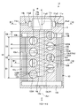
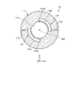
- 3 is a cross-sectional view taken along the line III-III in FIG. 4 is a cross-sectional view taken along the line IV-IV in FIG.
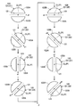
- FIG. 5 is a schematic and illustrative view showing a channel cross section at a plurality of positions S1 to S8 shown in FIG. 4 in one section of the passage included in the fluid passage device of the first embodiment. It is explanatory drawing.
- 6 is a flow path at a plurality of positions S1 to S8 shown in FIG. 4 in a section adjacent to the downstream of the section shown in FIG.
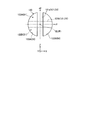
- FIG. 7 is a schematic and exemplary cross-sectional view showing the arrangement of the front end of the second partition and the rear end of the first partition in the passage included in the fluid passage device of the first embodiment.
- FIG. 8 is a schematic and exemplary cross-sectional view of a part of a modified fluid passage device.
- FIG. 9 is a schematic and exemplary cross-sectional view of the fluid passage device of the second embodiment.
- exemplary embodiments of a mixer structure, a fluid passage device, and a processing device are disclosed.
- the configurations and controls (technical features) of the embodiments described below, and the operations and results (effects) brought about by the configurations and controls are examples.
- an X direction, a Y direction, and a Z direction are shown.
- the X direction, the Y direction, and the Z direction are orthogonal to each other.
- FIG. 1 is a cross-sectional view of the semiconductor processing apparatus 1.
- the semiconductor processing apparatus 1 performs a predetermined process on the wafer W in a substantially cylindrical chamber 2 (processing container) constituted by a base 3 and a lid 4.
- the semiconductor processing apparatus 1 is, for example, a CVD (chemical vapor deposition) apparatus, and forms a silicon oxide film on the wafer W as an insulating film such as an interlayer insulating film.
- the base 3 and the lid 4 can also be referred to as wall portions.
- the semiconductor processing apparatus 1 is an example of a processing apparatus.
- the chamber 2 is an example of a processing unit.
- the wafer W is an example of an object to be processed.
- the lid 4 is provided with a shower mechanism 5 for supplying gas onto the wafer W.
- the shower mechanism 5 has a plurality of plates 51 and 52 arranged at intervals.
- the plates 51 and 52 are provided with through holes 51a and 52a through which gas passes.
- the specifications of the positions, number, size, etc. of the through holes 51a, 52a are set so that the variation in the gas supply amount depending on the location on the wafer W is minimized.
- the wafer W is supported by a disk-shaped stage 6.
- the stage 6 can support the wafer W so as to be rotatable around a central axis Ax along the thickness direction of the wafer W.
- the stage 6 can have a heater (not shown) that heats the wafer W.
- the lid 4 is provided with an air supply port 4a.
- the gas is introduced into the shower mechanism 5 and eventually into the chamber 2 through the air supply port 4a.
- the base 3 is provided with an exhaust port 3a and an exhaust passage 3b. The gas in the chamber 2 is exhausted through the exhaust port 3a and the exhaust passage 3b.
- FIG. 2 is a sectional view of the mixer 10
- FIG. 3 is a sectional view taken along the line III-III of FIG. 2
- FIG. 4 is a sectional view taken along the line IV-IV of FIG.
- a mixer 10 for mixing a plurality of gases is provided upstream of the air supply port 4a.
- the mixer 10 having a columnar appearance is disposed on the upper side of the center portion of the lid 4.
- the mixer 10 is an example of a mixer structure.
- the mixer 10 may be configured integrally with the lid 4, or may be configured separately from the lid 4 and attached to the lid 4.
- the center line of the cylindrical mixer 10 can be referred to as a center axis Ax1.
- the central axis Ax1 is the same as the central axis Ax of the stage 6.
- the axial direction, the radial direction, and the circumferential direction are directions based on the central axis Ax1.
- the mixer 10 is an example of a fluid passage device.
- the mixer 10 can be created by, for example, an additive manufacturing apparatus.
- the mixer 10 includes a premixing unit 11, a helical static mixer unit 12, and a rectifying unit 13.
- the premixing unit 11 is an example of a second mixing unit
- the helical static mixer unit 12 is an example of a first mixing unit.
- the premixing unit 11 promotes mixing of the plurality of gases by causing the plurality of gases to collide with each other.
- the premixing section 11 is provided with a first passage 11a, a second passage 11b, and a mixing chamber 11c.
- the first passage 11a and the second passage 11b introduce different gases into the mixing chamber 11c.
- the mixing chamber 11c the gas passing through the first passage 11a and the gas passing through the second passage 11b collide with each other.
- the mixing chamber 11c positioned downstream is configured in a cylindrical shape around the central axis Ax1, and is positioned in the center of the premixing section 11.
- the first passage 11a is located upstream of the mixing chamber 11c.
- the first passage 11a includes three series sections of an introduction portion 11a1, a circulation portion 11a2, and a jetting portion 11a3.
- the introduction part 11a1 extends radially inward from an introduction opening provided on the outer peripheral surface of the mixer 10.
- the circling part 11a2 is provided downstream of the introducing part 11a1.
- the circumferential portion 11a2 extends along the circumferential direction from the radially inner end of the introduction portion 11a1, that is, the downstream end of the introduction portion 11a1.
- the ejection part 11a3 is provided downstream of the circulation part 11a2.
- the ejection portion 11a3 extends from the end portion of the circumferential portion 11a2 opposite to the introduction portion 11a1, that is, the downstream end portion of the circumferential portion 11a2, to the ejection opening of the mixing chamber 11c along the radial inner side.
- the gas is introduced into the mixing chamber 11c through the introduction part 11a1, the circulation part 11a2, and the ejection part 11a3.
- the cross-sectional area of the flow passage section of the ejection portion 11a3, for example, the cross section orthogonal to the flow direction, is smaller than the flow passage cross section of the rotating portion 11a2.
- the gas is ejected from the ejection part 11a3 into the mixing chamber 11c at a speed higher than that in the circulating part 11a2.
- the ejection part 11a3 may also be referred to as a nozzle part, a throttle part, or an orifice.
- the second passage 11b is located upstream of the mixing chamber 11c.
- the second passage 11b includes three serial sections of an introduction part 11b1, a circulation part 11b2, and an ejection part 11b3.
- the introduction portion 11b1 extends radially inward from an introduction opening provided on the outer peripheral surface of the mixer 10.
- the circling part 11b2 is provided downstream of the introducing part 11b1.
- the circulating portion 11b2 extends along the circumferential direction from the radially inner end of the introduction portion 11b1, that is, the downstream end of the introduction portion 11b1.
- the ejection part 11b3 is provided downstream of the circulation part 11b2.
- the ejection part 11b3 extends from the end of the circumferential part 11b2 opposite to the introduction part 11b1, that is, from the downstream end of the circumferential part 11b2, to the ejection opening of the mixing chamber 11c along the radial inner side.
- the gas is introduced into the mixing chamber 11c through the introduction portion 11b1, the circulation portion 11b2, and the ejection portion 11b3.
- the cross-sectional area of the flow passage section of the ejection portion 11b3, for example, the cross section orthogonal to the flow direction, is smaller than the flow passage cross section of the rotating portion 11b2.
- the gas is ejected from the ejection part 11b3 into the mixing chamber 11c at a speed higher than that in the circulating part 11b2.
- the ejection part 11b3 may also be referred to as a nozzle part, a throttle part, or an orifice.
- the second passage 11b is provided so as to be symmetric with respect to the first passage 11a with respect to the central axis Ax1. Further, the ejection portion 11a3 of the first passage 11a and the ejection portion 11b3 of the second passage 11b face each other across the central axis Ax1 and extend in the radial direction.
- the gas jet from the ejection part 11a3 and the gas jet from the ejection part 11b3 collide from opposite directions.
- the jets of the plurality of gases collide with each other, thereby promoting the mixing of the plurality of gases.
- mixing of the plurality of gases can be further promoted by the collision of the plurality of gas jets from opposite directions.
- the mixing chamber 11 c of the premixing unit 11 and the passage 120 of the helical static mixer unit 12 are connected via a communication passage 14.
- the communication passage 14 has a cylindrical vertical hole portion 14a extending in the axial direction at a position overlapping the central axis Ax1, and a horizontal hole portion extending in the radial direction from the end of the vertical hole portion 14a opposite to the mixing chamber 11c. 14b.
- the vertical hole portion 14a is an example of an introduction passage.
- the helical static mixer unit 12 has a spiral (string winding) passage 120 extending along the central axis Ax1 while twisting around the central axis Ax1.
- the passage 120 is located between the upstream end portion connected to the lateral hole portion 14 b of the communication passage 14 and the downstream end portion connected to the lateral hole portion 13 a of the rectifying portion 13.
- the spiral passage 120 can be defined as follows.
- the position coordinates (p x , p y , p z ) of the point P (cross-sectional center) of the cross-sectional center line CL of the passage 120 can be expressed as, for example, the following equations (1) to (3).
- p x R ⁇ cos ⁇ (1)
- p y R ⁇ sin ⁇ (2)
- p z h ⁇ ⁇ (3)
- p x is the position coordinate in the X direction of the point P
- p y the position coordinates of the Y-direction of the point P
- p z the Z direction coordinate of the point P
- theta parametric the central axis Ax1 around
- R is the radius of the helix
- h is a coefficient proportional to the pitch of the helix (interval in the Z direction).
- the cross section of the flow path may be along a plane including the central axis Ax1, or may be orthogonal to the tangential direction of the point P of the cross section center line CL.
- Unit vectors (t x , t y , t z ) in the tangential direction at the point P of the cross-section center line CL can be expressed as the following equations (4) to (6).
- t x ⁇ sin ⁇ ⁇ sin ⁇ (4)
- t y sin ⁇ ⁇ cos ⁇ (5)
- t z cos ⁇ (6)
- the flow path cross section at the point P is a plane that passes through the point P and has the tangential direction of the cross section center line CL at the point P as the normal direction.
- path 120 can be defined as the tangential direction in the point P of the spiral cross-section centerline CL, for example.
- the cross-sectional center in each channel cross section that is, the point P is the geometric center of gravity of the opening portion of the passage 120 in each channel cross section.
- the passage 120 includes a plurality of series sections.
- the passage includes four sections D1 to D4.
- the lengths of the plurality of sections may be the same or different.
- a partition 121 is provided in each of the sections D1 to D4.
- the partition 121 divides the passage 120 into a plurality of parallel shunts 122A and 122B.
- the partition wall 121 divides the passage 120 into two parallel shunts 122A and 122B.
- the cross-sectional shape of the shunts 122A and 122B is D-shaped, and the two shunts 122A and 122B are arranged such that the D-shaped straight line portions are parallel to each other and the D-shaped curvilinear portions are parallel to each other. It arrange
- the shape of the partition wall 121 is a strip shape that passes through the center of the cross section (point P) and extends linearly in one direction with a constant width. That is, the partition wall 121 is a portion between two D-shaped straight portions in each channel cross section, and the passage 120 is divided so that the cross-sectional areas of the two shunts 122A and 122B are the same.
- the passage 120 that has a circular cross section and extends in a spiral shape has a plurality of parallel partition walls 121A and 122B that are substantially the same in volume.
- the shunts 122A and 122B are divided.
- the cross-sectional areas of the shunts 122A and 122B are constant in the sections D1 to D4, but may vary.
- the helical static mixer unit 12 is an example of a mixer structure.
- FIG. 5 is an explanatory diagram showing a cross section of the flow path at a plurality of positions S1 to S8 (cross-sectional lines and angles) shown in FIG. 4 in the section D1 of the passage 120.
- the position S1 is the most upstream
- the position S8 is the most downstream
- the positions S1 to S8 are more downstream as the attached numbers are larger.
- the partition wall 121 extending in the direction d1 intersecting the cross-section center line CL is gradually twisted in the clockwise direction toward the downstream.
- the partition wall 121 is rotated 360 ° around the sectional center line CL while the passage 120 is spirally rotated 360 ° around the central axis.
- the gas flow in the shunts 122 ⁇ / b> A and 122 ⁇ / b> B becomes a spiral vortex along the partition wall 121, so that mixing of a plurality of gases is promoted.
- the direction d1 is an example of a first direction.
- FIG. 6 is an explanatory diagram showing a channel cross section at positions S1 to S8 (cross-sectional lines and angles) shown in FIG. 4 in the section D2 adjacent to the downstream of the section D1.
- the partition wall 121 extending in the direction d2 intersecting the cross section center line CL is gradually twisted in the counterclockwise direction toward the downstream.
- the partition wall 121 is rotated 360 ° around the cross-sectional center line CL while the passage 120 is spirally rotated 360 ° around the central axis.
- the gas flow in the shunts 122 ⁇ / b> A and 122 ⁇ / b> B becomes a spiral vortex along the partition wall 121, so that mixing of a plurality of gases is promoted.
- the direction d2 is an example of the second direction.
- the twist direction of the partition wall 121 that twists toward the downstream is different in the two sections D1 and D2 adjacent to each other in the flow direction. Therefore, compared to the case where the twist direction of the partition wall 121 is the same in the two sections D1 and D2 adjacent to each other in the flow direction, the flow is more easily disturbed, and as a result, the mixing of a plurality of gases can be further promoted.
- the partition 121 in the upstream section D1 is an example of a first partition
- the shunts 122A and 122B in the upstream section D1 are an example of a first shunt.
- the partition 121 in the downstream section D2 is an example of the second partition
- the shunts 122A and 122B in the downstream section D2 are the second This is an example of the shunt.
- FIG. 7 is an explanatory diagram showing a front end 121a of the partition 121 in the section D2 and a rear end 121b of the partition 121 in the section D1 adjacent to the upstream of the section D2.
- the front end 121a is an upstream end portion of the partition wall 121 in the section D2, and extends linearly along the Z direction (direction d2) that is the width direction of the passage 120.
- the rear end 121b is a downstream end portion of the partition wall 121 in the section D1, and extends linearly along the X direction (direction d1) that is the width direction of the passage.
- the gas in the two shunts 122A and 122B in the upstream section D1 flows into the two shunts 122A and 122B in the downstream section D2 approximately in half.
- the flow is divided and mixed 2n times, so that the gas depending on the location of the channel cross section The variation in the components tends to be smaller.
- the rear end 121b of the partition 121 in the upstream section D1 and the front end 121a of the partition 121 in the downstream section D2 are in contact with each other, and although they intersect, they may be separated from each other, for example, the central portions face each other with a gap.
- the rear end 121b of the partition 121 in the upstream section and the front end 121a of the partition 121 in the downstream section need only be in a twisted position.
- the passage 120 further includes a section D3 downstream from the section D2 and a section D4 downstream from the section D3.
- the section D3 has the same shape as the section D1
- the section D4 has the same shape as the section D2.
- the section D4 is half the length of the section D2, that is, a length of 180 ° around the central axis Ax1.
- the rectifying unit 13 includes a lateral hole portion 13 a, a third passage 13 b, a rectifying passage 13 c, and a fourth passage 13 d.
- the lateral hole portion 13a connects the downstream end of the section D4 of the passage 120 and the third passage 13b.
- the lateral hole portion 13 a can be referred to as an introduction portion of the rectifying portion 13.
- the third passage 13b is formed in an annular shape.
- the rectifying passage 13c is connected to one of the third passages 13b in the axial direction (downward in FIG. 2), and has a cylindrical shape surrounding the helical static mixer portion 12.
- the rectifying passage 13c includes a plurality of parallel holes 13c1 extending along the axial direction of the cylinder (center axis Ax1).
- the cross-sectional shape of the hole 13c1 is, for example, a mesh shape in which a plurality of quadrangles are densely arranged.
- the cross-sectional shape of the hole 13c1 is not limited to a square shape, and may be, for example, a circular shape, an elliptical shape, a hexagonal shape, or the like.
- the rectifying passage 13c has a honeycomb structure. As shown in FIG.
- the fourth passage 13d is configured in a flat cylindrical shape and is connected to the plurality of holes 13c1.
- the gas that has passed through the fourth passage 13 d is introduced into the air inlet 4 a of the lid 4 through the exhaust hole 10 a of the mixer 10. According to such a configuration, the gas is introduced into the chamber 2 while being rectified by the rectifying passage 13 c of the rectifying unit 13.
- the rear end 121b of the partition 121 (first partition) in the section D1 and the front end 121a of the partition 121 (second partition) in the section D2 intersect each other. Yes. Therefore, for example, in two sections D1 and D2 adjacent to each other in the flow direction, flow disturbance is more likely to occur than when the rear end 121b of the upstream partition 121 and the front end 121a of the downstream partition 121 are parallel to each other. Thus, the mixing of a plurality of gases can be further promoted.
- the partition 121 in the section D1 is twisted in the clockwise direction around the cross-sectional center line CL
- the partition 121 in the section D2 is twisted in the counterclockwise direction around the cross-sectional center line CL.
- the two sections D1 and D2 adjacent in the flow direction have different twisting directions of the partition wall 121. For example, compared to the case where the twisting directions are the same, the flow is more easily disturbed. Mixing of a plurality of gases can be further promoted.
- the communication passage 14 extends along the central axis Ax1, and the gas passing through the communication passage 14 is directed toward one side (downward in FIG. 2) in the Z direction along the central axis Ax1.
- the passage 120 is provided so as to be spirally wound around the communication passage 14, and the gas passing through the passage 120 spirally flows along the central axis Ax1 toward the other side in the Z direction (upward in FIG. 2).
- the rectifying passage 13c extends along the central axis Ax1 at a position surrounding the outer periphery of the spiral passage 120 on the opposite side of the communication passage 14 of the passage 120, and the gas passing through the rectifying passage 13c passes through the central axis Ax1.
- the communication passage 14, the spiral passage 120, and the rectification passage 13c can be efficiently arranged in a relatively small volume, and the communication passage 14, the spiral passage 120, and the rectification passage 13c are provided.
- the mixer 10 can be configured more compactly. Further, since the rectifying passage 13c is longer in the axial direction, the turbulence caused by the swirling of the flow generated in the helical static mixer portion 12 is more easily settled.
- the mixer 10 includes a helical static mixer unit 12.
- the static mixer is provided in the spiral passage 120, for example, the amount of centrifugal force acting on the fluid is compared with the configuration in which the static mixer is provided in the linear passage. It is easy to promote mixing. Further, according to the present embodiment, for example, the static mixer is easily configured more compactly.
- FIG. 8 is a cross-sectional view of a part of the mixer 10A of the present modification.
- the mixer 10A of this modification also has the same configuration as the mixer 10 of the above embodiment. Therefore, also with the mixer 10A, an operation and a result (effect) based on the same configuration as the mixer 10 can be obtained.
- the column 16 is provided in the middle of the sections D1 and D2 of the shunts 122A and 122B.
- the support column 16 is a bridge portion that connects the first portion 122a1 and the second portion 122a2 of the inner surface 122a of the shunts 122A and 122B.
- the first portion 122a1 is a cylindrical surface portion of the inner surface 122a
- the second portion 122a2 is a planar portion that faces the first portion 122a1 and extends along the partition wall 121.
- the support column 16 may have a prismatic shape, a cylindrical shape, or another cross-sectional shape.
- the support column 16 can also be referred to as a protrusion. Since the column 16 is provided so as to partially block the middle of the shunts 122 ⁇ / b> A and 122 ⁇ / b> B, the gas flow is separated from the surface of the column 16, and a vortex is generated downstream of the column 16. That is, since the gas flow is disturbed by the support columns 16, the mixing of a plurality of gases is more easily promoted.
- the support column 16 is an example of a vortex generating element.
- the vortex generating element is not limited to the support column 16 and may be various structures such as a protrusion or a lattice (lattice structure).
- the vortex generating element can also be called an obstacle, a resistance element, an agitation promoting element, or the like.
- the support column 16 extends in the Z direction, that is, along the central axis Ax1, and a plurality of support columns 16 are arranged along the central axis Ax1. Therefore, the column 16 functions as a support portion that supports the partition wall 121 and the peripheral wall 123 of the passage 120.
- FIG. 9 is a cross-sectional view of the mixer 10B of the second embodiment.
- the mixer 10B also has the same configuration as the mixer 10 of the first embodiment. Therefore, the operation and result (effect) based on the same configuration as the mixer 10 can be obtained also by the mixer 10B.
- the position and configuration of the rectifying unit 13B are different. That is, as shown in FIG. 9, in the present embodiment, the premixing unit 11, the helical static mixer unit 12, and the rectifying unit 13B are arranged in the axial direction along the central axis Ax1.
- the mixer 10B can be made smaller, that is, thinner, in the radial direction of the central axis Ax1.
- the configuration of the helical static mixer unit 12 is the same as that of the first embodiment, but in this embodiment, the upper side of FIG. 9 (the premixing unit 11 side) is upstream of the passage 120, and the lower side of FIG. The side (rectifying unit 13B) side is downstream of the passage 120. That is, the gas flows through the helical static mixer unit 12 in the order of the section D4, the section D3, the section D2, and the section D1 in the opposite direction to the first embodiment.
- the rectification unit 13B includes a horizontal hole part 13a, a vertical hole part 13e, a fifth passage 13f, a rectification passage 13c, and a sixth passage 13g.
- the horizontal hole 13a connects the downstream end of the section D4 of the passage 120 and the vertical hole 13e.
- the lateral hole portion 13a can be referred to as an introduction portion of the rectifying portion 13B.
- the vertical hole portion 13e extends in a cylindrical shape along the axial direction at a position overlapping the central axis Ax1.
- the fifth passage 13f is connected to the vertical hole 13e and is formed in a flat cylindrical shape.
- the rectifying passage 13c is connected to one of the fifth passages 13f in the axial direction (downward in FIG.
- the sixth passage 13g is connected to one of the rectifying passages 13c in the axial direction (downward in FIG. 2) and is formed in a flat cylindrical shape.
- the gas that has passed through the sixth passage 13g is introduced into the air inlet 4a of the lid 4 through the exhaust hole 10a of the mixer 10. The gas is rectified when passing through the rectification passage 13c from the fifth passage 13f to the sixth passage 13g.
- the mixer structure and the fluid passage device can be used in devices other than semiconductor manufacturing devices, or can be used alone. Further, the mixer structure and the fluid passage device can be applied not only to gas but also to liquid, plasma, multiphase flow, gel, gas containing powder, fluid solid, and the like. An object having such fluidity is called a fluid.
- specifications such as a passage, a shunt, a partition, a spiral, and a channel cross section can be variously changed and implemented.
- the channel cross section is not limited to a circular shape.
- the number of divisions of the shunts by the partition walls may be three or more, and the amount of twist of the partition walls, the length of the section, and the like may be variously set. The direction of the spiral, the number of turns, and the like can be variously set.
Landscapes
- Chemical & Material Sciences (AREA)
- Chemical Kinetics & Catalysis (AREA)
- Dispersion Chemistry (AREA)
- General Chemical & Material Sciences (AREA)
- Engineering & Computer Science (AREA)
- Materials Engineering (AREA)
- Mechanical Engineering (AREA)
- Metallurgy (AREA)
- Organic Chemistry (AREA)
Abstract
実施形態の、流体の螺旋状の通路が設けられたミキサ構造は、第一の隔壁と、第二の隔壁と、を有する。第一の隔壁は、通路の断面中心線と交差して延び、螺旋状の通路を複数の並列な第一の分路に分ける。第二の隔壁は、第一の隔壁の下流に位置され、断面中心線と交差して延び、螺旋状の通路を複数の並列な第二の分路に分ける。第一の隔壁の下流の端部である後端と、第二の隔壁の上流の端部である前端とは、交差するかあるいはねじれの位置にある。
Description
実施形態は、ミキサ構造、流体通路装置、および処理装置に関する。
従来、混合されたガスが処理を用いて所定の処理を実行する処理装置が知られている。
例えば、ガス等の流体をより均一にあるいはより効率良く混合することができるミキサ構造が得られば、有益である。
実施形態の、流体の螺旋状の通路が設けられたミキサ構造は、第一の隔壁と、第二の隔壁と、を有する。第一の隔壁は、通路の断面中心線と交差して延び、螺旋状の通路を複数の並列な第一の分路に分ける。第二の隔壁は、第一の隔壁の下流に位置され、断面中心線と交差して延び、螺旋状の通路を複数の並列な第二の分路に分ける。第一の隔壁の下流の端部である後端と、第二の隔壁の上流の端部である前端とは、交差するかあるいはねじれの位置にある。
以下、ミキサ構造、流体通路装置、および処理装置の例示的な実施形態が開示される。以下に示される実施形態の構成や制御(技術的特徴)、ならびに当該構成や制御によってもたらされる作用および結果(効果)は、一例である。図中には、説明の便宜上、X方向、Y方向、およびZ方向が示されている。X方向、Y方向、およびZ方向は、互いに直交している。
また、以下の実施形態や変形例には、同様の構成要素が含まれている。以下では、それら同様の構成要素には共通の符号が付与されるとともに、重複する説明が省略される場合がある。
<第1実施形態>
図1は、半導体処理装置1の断面図である。半導体処理装置1は、ベース3と蓋4とによって構成された略円筒状のチャンバ2(処理容器)内で、ウエハWに所定の処理を施す。この半導体処理装置1は、例えば、CVD(chemical vapor deposition)装置であって、ウエハW上に、層間絶縁膜等の絶縁膜として、シリコン酸化膜を形成する。なお、ベース3や蓋4は、壁部とも称されうる。半導体処理装置1は、処理装置の一例である。チャンバ2は、処理部の一例である。ウエハWは、被処理物の一例である。
図1は、半導体処理装置1の断面図である。半導体処理装置1は、ベース3と蓋4とによって構成された略円筒状のチャンバ2(処理容器)内で、ウエハWに所定の処理を施す。この半導体処理装置1は、例えば、CVD(chemical vapor deposition)装置であって、ウエハW上に、層間絶縁膜等の絶縁膜として、シリコン酸化膜を形成する。なお、ベース3や蓋4は、壁部とも称されうる。半導体処理装置1は、処理装置の一例である。チャンバ2は、処理部の一例である。ウエハWは、被処理物の一例である。
蓋4には、ウエハW上にガスを供給するシャワー機構5が設けられている。シャワー機構5は、間隔をあけて配置された複数のプレート51,52を有する。プレート51,52には、ガスが通る貫通孔51a,52aが設けられている。貫通孔51a,52aの位置や、数、大きさ等のスペックは、ウエハW上の場所によるガスの供給量のばらつきが極力小さくなるよう、設定されている。
チャンバ2内で、ウエハWは、円板状のステージ6に支持されている。ステージ6は、ウエハWを、ウエハWの厚さ方向に沿った中心軸Ax回りに回転可能に、支持することができる。また、ステージ6は、ウエハWを加熱する不図示のヒータを有することができる。
蓋4には、給気口4aが設けられている。ガスは、給気口4aを経由してシャワー機構5、ひいてはチャンバ2内に導入される。また、ベース3には、排気口3aと、排気通路3bとが設けられている。チャンバ2内のガスは、排気口3aおよび排気通路3bを経由して排出される。
図2は、ミキサ10の断面図、図3は、図2のIII-III断面図、図4は、図2のIV-IV断面図である。図1に示されるように、本実施形態では、給気口4aの上流に、複数のガスを混合するミキサ10が設けられている。具体的には、例えば、円柱状の外観を有したミキサ10が、蓋4の中央部の上側に配置されている。ミキサ10は、ミキサ構造の一例である。なお、ミキサ10は、蓋4と一体に構成されてもよいし、蓋4とは別に構成され、蓋4に取り付けられてもよい。なお、円柱状のミキサ10の中心線は、中心軸Ax1と称されうる。中心軸Ax1は、ステージ6の中心軸Axと同じである。以下の説明において、軸方向、径方向、および周方向は、中心軸Ax1を基準とした方向である。ミキサ10は、流体通路装置の一例である。ミキサ10は、例えば、積層造形装置によって作成されうる。
ミキサ10は、予混合部11と、ヘリカルスタティックミキサ部12と、整流部13と、を有する。予混合部11は、第二の混合部の一例であり、ヘリカルスタティックミキサ部12は、第一の混合部の一例である。
予混合部11は、複数のガスを互いに衝突させることにより、当該複数のガスの混合を促進する。図3に示されるように、予混合部11には、第一の通路11a、第二の通路11b、および混合室11cが設けられている。第一の通路11aおよび第二の通路11bは、それぞれ異なるガスを、混合室11c内に導入する。混合室11c内で、第一の通路11aを通ったガスと、第二の通路11bを通ったガスとが、互いに衝突する。
予混合部11内では下流に位置される混合室11cは、中心軸Ax1回りの円筒状に構成され、予混合部11の中央部に位置されている。
第一の通路11aは、混合室11cよりも上流に位置される。第一の通路11aは、導入部11a1、周回部11a2、および噴出部11a3の三つの直列な区間を含む。導入部11a1は、ミキサ10の外周面に設けられた導入開口から径方向内方に向けて延びている。周回部11a2は、導入部11a1の下流に設けられている。周回部11a2は、導入部11a1の径方向内方の端部、すなわち導入部11a1の下流の端部から、周方向に沿って延びている。噴出部11a3は、周回部11a2の下流に設けられている。噴出部11a3は、周回部11a2の導入部11a1とは反対側の端部、すなわち周回部11a2の下流の端部から、径方向内方に沿って混合室11cの噴出開口まで延びている。このような構成の第一の通路11aにおいて、ガスは、導入部11a1、周回部11a2、および噴出部11a3を経て、混合室11c内に導入される。ここで、図2から明らかとなるように、噴出部11a3の流路断面、例えば流れ方向と直交する断面の断面積は、周回部11a2の流路断面よりも小さい。よって、ガスは、噴出部11a3から、混合室11c内に、周回部11a2内での速度よりも高い速度で噴出する。噴出部11a3は、ノズル部、絞り部、またはオリフィスとも称されうる。
第二の通路11bは、混合室11cよりも上流に位置される。第二の通路11bは、導入部11b1、周回部11b2、および噴出部11b3の三つの直列な区間を含む。導入部11b1は、ミキサ10の外周面に設けられた導入開口から径方向内方に向けて延びている。周回部11b2は、導入部11b1の下流に設けられている。周回部11b2は、導入部11b1の径方向内方の端部、すなわち導入部11b1の下流の端部から、周方向に沿って延びている。噴出部11b3は、周回部11b2の下流に設けられている。噴出部11b3は、周回部11b2の導入部11b1とは反対側の端部、すなわち周回部11b2の下流の端部から、径方向内方に沿って混合室11cの噴出開口まで延びている。このような構成の第二の通路11bにおいて、ガスは、導入部11b1、周回部11b2、および噴出部11b3を経て、混合室11c内に導入される。ここで、図2から明らかとなるように、噴出部11b3の流路断面、例えば流れ方向と直交する断面の断面積は、周回部11b2の流路断面よりも小さい。よって、ガスは、噴出部11b3から、混合室11c内に、周回部11b2内での速度よりも高い速度で噴出する。噴出部11b3は、ノズル部、絞り部、またはオリフィスとも称されうる。図2から明らかとなるように、第二の通路11bは、中心軸Ax1について第一の通路11aと対称となるよう、設けられている。また、第一の通路11aの噴出部11a3と第二の通路11bの噴出部11b3とが、中心軸Ax1を挟んで互いに面し、径方向に延びている。よって、混合室11c内において、噴出部11a3からのガスの噴流と、噴出部11b3からのガスの噴流とが、反対方向から衝突する。このように複数のガスの噴流が互いに衝突することにより、複数のガスの混合が促進される。また、複数のガスの噴流が互いに反対方向から衝突することにより、当該複数のガスの混合がより一層促進されうる。
予混合部11の混合室11cとヘリカルスタティックミキサ部12の通路120とは、連絡通路14を介して接続されている。連絡通路14は、中心軸Ax1と重なる位置で軸方向に延びた円筒状の縦孔部14aと、縦孔部14aの混合室11cとは反対側の端部から径方向に延びた横孔部14bと、を含む。縦孔部14aは、導入通路の一例である。
図2に示されるように、ヘリカルスタティックミキサ部12は、中心軸Ax1回りにねじれながら中心軸Ax1に沿って延びた螺旋状(弦巻線状)の通路120を有する。通路120は、連絡通路14の横孔部14bと接続された上流の端部と、整流部13の横孔部13aと接続された下流の端部とのに間に位置する。螺旋状の通路120は、一例としては、以下のように定義できる。通路120の断面中心線CLの点P(断面中心)の位置座標(px,py,pz)は、例えば、次の式(1)~(3)のように表すことができる。
px=R・cosθ ・・・(1)
py=R・sinθ ・・・(2)
pz=h・θ ・・・(3)
ここに、pxは、点PのX方向の位置座標、pyは、点PのY方向の位置座標、pzは、点PのZ方向の座標、θは媒介変数(中心軸Ax1回りの角度)、Rは、螺旋の半径、hは螺旋のピッチ(Z方向の間隔)に比例する係数である。
px=R・cosθ ・・・(1)
py=R・sinθ ・・・(2)
pz=h・θ ・・・(3)
ここに、pxは、点PのX方向の位置座標、pyは、点PのY方向の位置座標、pzは、点PのZ方向の座標、θは媒介変数(中心軸Ax1回りの角度)、Rは、螺旋の半径、hは螺旋のピッチ(Z方向の間隔)に比例する係数である。
流路断面は、中心軸Ax1を含む平面に沿ってもよいし、断面中心線CLの点Pの接線方向と直交してもよい。断面中心線CLの点Pにおける接線方向の単位ベクトル(tx,ty,tz)は、次の式(4)~(6)のように表すことができる。
tx=-sinα・sinθ ・・・(4)
ty=sinα・cosθ ・・・(5)
tz=cosα ・・・(6)
ここに、cosα=h、sinα=Rである。この場合、点Pでの流路断面は、点Pを通り、点Pでの断面中心線CLの接線方向を法線方向とする面である。なお、通路120における流れ方向は、例えば、螺旋状の断面中心線CLの点Pにおける接線方向と定義できる。
tx=-sinα・sinθ ・・・(4)
ty=sinα・cosθ ・・・(5)
tz=cosα ・・・(6)
ここに、cosα=h、sinα=Rである。この場合、点Pでの流路断面は、点Pを通り、点Pでの断面中心線CLの接線方向を法線方向とする面である。なお、通路120における流れ方向は、例えば、螺旋状の断面中心線CLの点Pにおける接線方向と定義できる。
また、各流路断面における断面中心、すなわち点Pは、各流路断面における通路120の開口部分の幾何学的な重心とする。
通路120は、直列な複数の区間を含む。図2の例では、通路は、四つの区間D1~D4を含む。複数の区間の長さは同じであってもよいし、異なってもよい。
区間D1~D4には、それぞれ、隔壁121が設けられている。隔壁121は、通路120を、並列な複数の分路122A,122Bに分ける。図2の例では、隔壁121は、通路120を、並列な二つの分路122A,122Bに分けている。各流路断面において、分路122A,122Bの断面形状はD字状であり、二つの分路122A,122Bは、D字の直線部が間隔を開けて平行に並ぶとともにD字の曲線部が一つの円周上に位置されるように、すなわち、線対称または点対称に、配置されている。また、各流路断面において、隔壁121の形状は、断面中心(点P)を通り一定幅で一方向に直線状に延びる帯状である。すなわち、隔壁121は、各流路断面において、二つのD字の直線部の間の部分であり、二つの分路122A,122Bの断面積が同じになるように、通路120を分けている。換言すれば、円形断面を有して螺旋状に延びた通路120を、螺旋状に延びた板状の隔壁121が、各分路122A,122Bの容積が略同じになるように、並列な複数の分路122A,122Bに区分している。なお、分路122A,122Bの断面積は、区間D1~D4中で一定であるが、変化してもよい。ヘリカルスタティックミキサ部12は、ミキサ構造の一例である。
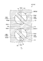
図5は、通路120の区間D1中の、図4中に示された複数の位置S1~S8(断面線、角度)での流路断面を示す、説明図である。位置S1が最も上流であり、位置S8が最も下流であり、位置S1~S8は、添付の数字が大きいほど、下流である。図5の例では、流路断面を周方向かつ下流方向に見た場合、断面中心線CLと交差した方向d1に延びた隔壁121は、下流に向かうにつれて徐々に時計回り方向にねじれている。区間D1では、通路120が螺旋状に中心軸回りに360°回転する間に、隔壁121は、断面中心線CL回りに360°回転している。このような構成により、分路122A,122B内のガスの流れは、隔壁121に沿った螺旋状の渦流になるため、複数のガスの混合が促進される。方向d1は、第一の方向の一例である。
図6は、区間D1の下流に隣接した区間D2中の、図4中に示された位置S1~S8(断面線、角度)での流路断面を示す説明図である。図6の例では、流路断面を周方向かつ下流方向に見た場合、断面中心線CLと交差した方向d2に延びた隔壁121は、下流に向かうにつれて徐々に反時計回り方向にねじれている。区間D2では、通路120が螺旋状に中心軸回りに360°回転する間に、隔壁121は、断面中心線CL回りに360°回転している。このような構成により、分路122A,122B内のガスの流れは、隔壁121に沿った螺旋状の渦流になるため、複数のガスの混合が促進される。方向d2は、第二の方向の一例である。
また、図5,6を比較すれば明らかとなるように、流れ方向に隣接する二つの区間D1,D2で、下流に向かうにつれてねじれる隔壁121のねじれ方向が異なっている。よって、流れ方向に隣接する二つの区間D1,D2で隔壁121のねじれ方向が同じである場合に比べて、流れの乱れが生じ易くなり、ひいては、複数のガスの混合がより一層促進されうる。二つの区間D1,D2のうち、上流の区間D1における隔壁121は、第一の隔壁の一例であり、上流の区間D1における分路122A,122Bは、第一の分路の一例である。また、流れ方向に直列に隣接する二つの区間D1,D2のうち、下流の区間D2における隔壁121は、第二の隔壁の一例であり、下流の区間D2における分路122A,122Bは、第二の分路の一例である。
図7は、区間D2の隔壁121の前端121aと、区間D2の上流に隣接した区間D1の隔壁121の後端121bと、を示す説明図である。前端121aは、区間D2の隔壁121の上流の端部であって、通路120の幅方向であるZ方向(方向d2)に沿って直線状に延びている。これに対し、後端121bは、区間D1の隔壁121の下流の端部であって、通路の幅方向であるX方向(方向d1)に沿って直線状に延びている。この図7から明らかとなるように、区間D1の隔壁121の後端121bと、区間D1の下流に隣接した区間D2の隔壁121の前端121aとは、互いに交差している。よって、二つの区間D1,D2において、上流の区間D1の隔壁121の後端121bと下流の区間D2の隔壁121の前端121aとが互いに平行である場合に比べて、流れの乱れが生じ易くなり、ひいては、複数のガスの混合がより一層促進されうる。また、図7の例では、流路断面を下流側に見た場合に、区間D1の後端121bと区間D2の前端121aとは、互いに直交している。よって、下流の区間D2の二つの分路122A,122B内には、それぞれ、上流の区間D1の二つの分路122A,122B内のガスが、略半分ずつ流入する。このような前端121aおよび後端121bを有した区間の組み合わせの数がn個である場合にあっては、流れが、2n回、分割されかつ混合されるため、流路断面の場所によるガスの成分のばらつきがより小さくなりやすい。なお、この例では、直列に隣接する二つの区間D1,D2において、上流の区間D1の隔壁121の後端121bと、下流の区間D2の隔壁121の前端121aとは、互いに接しており、互いに交差しているが、これらは、中央部同士が隙間をあけて面するなど、互いに離間していてもよい。離間している場合にあっては、上流の区間の隔壁121の後端121bと、下流の区間の隔壁121の前端121aとは互いにねじれの位置にあればよい。
通路120には、さらに、区間D2よりも下流の区間D3と、当該区間D3よりも下流の区間D4とが含まれている。区間D3は区間D1と同一の形状を有し、区間D4は区間D2と同一の形状を有する。ただし、区間D4は、区間D2の半分の長さ、すなわち、中心軸Ax1周りに180°分の長さである。
整流部13は、図2に示されるように、横孔部13a、第三の通路13b、整流通路13c、および第四の通路13dを含んでいる。横孔部13aは、通路120の区間D4の下流の端部と第三の通路13bとを接続している。横孔部13aは、整流部13の導入部と称されうる。第三の通路13bは、円環状に構成されている。整流通路13cは、第三の通路13bの軸方向一方(図2では下方)に連なり、ヘリカルスタティックミキサ部12の周囲を取り囲む円筒状に構成されている。整流通路13cは、円筒の軸方向(中心軸Ax1)に沿って延びる複数の並列な孔部13c1を含んでいる。図4に示されるように、孔部13c1の断面形状は、例えば、複数の四角形が密集配置されたメッシュ状である。なお、孔部13c1の断面形状は、四角形状には限定されず、例えば、円形状や、楕円形状、六角形状等であってもよい。孔部13c1の断面形状が六角形状である場合、整流通路13cは、ハニカム構造である。第四の通路13dは、図2に示されるように、偏平な円筒状に構成され、複数の孔部13c1と繋がっている。第四の通路13dを経由したガスは、ミキサ10の排気孔10aを経由して、蓋4の給気口4aに導入される。このような構成によれば、整流部13の整流通路13cによって整流された状態で、ガスがチャンバ2内に導入される。
以上、説明したように、本実施形態では、区間D1の隔壁121(第一の隔壁)の後端121bと、区間D2の隔壁121(第二の隔壁)の前端121aとが、互いに交差している。よって、例えば、流れ方向に隣接する二つの区間D1,D2において、上流の隔壁121の後端121bと下流の隔壁121の前端121aとが互いに平行である場合に比べて、流れの乱れが生じ易くなり、ひいては、複数のガスの混合がより一層促進されうる。
また、本実施形態では、区間D1の隔壁121は、断面中心線CL回りに時計回り方向にねじれ、区間D2の隔壁121は、断面中心線CL回りに反時計回り方向にねじれている。このように、流れ方向に隣接する二つの区間D1,D2について、隔壁121のねじれ方向が互いに異なるため、例えば、ねじれ方向が同じである場合に比べて、流れの乱れが生じ易くなり、ひいては、複数のガスの混合がより一層促進されうる。
また、本実施形態では、連絡通路14(導入通路)が中心軸Ax1に沿って延び、連絡通路14を通るガスは、中心軸Ax1に沿ったZ方向の一方(図2の下方)に向けて流れる。通路120は、連絡通路14の回りを螺旋状に巻くように設けられ、通路120を通るガスは、中心軸Ax1に沿って螺旋状にZ方向の他方(図2の上方)に向けて流れる。また、整流通路13cは、通路120の連絡通路14の反対側、すなわち螺旋状の通路120の外周を取り囲む位置で、中心軸Ax1に沿って延び、整流通路13cを通るガスは、中心軸Ax1に沿ったZ方向の一方(図2の下方)に向けて流れる。よって、例えば、連絡通路14、螺旋状の通路120、および整流通路13cを比較的小さな容積に効率良く配置することができ、当該連絡通路14、螺旋状の通路120、および整流通路13cが設けられたミキサ10を、よりコンパクトに構成することができる。また、整流通路13cが軸方向により長くなる分、ヘリカルスタティックミキサ部12において生じた流れの旋回による乱れが、より収まりやすい。
また、本実施形態では、ミキサ10は、ヘリカルスタティックミキサ部12を有する。本実施形態によれば、螺旋状の通路120にスタティックミキサが設けられているため、直線状の通路にスタティックミキサが設けられた構成に比べて、例えば、流体に遠心力が作用する分、流体の混合が促進されやすい。また、本実施形態によれば、例えば、スタティックミキサがよりコンパクトに構成されやすい。
<変形例>
図8は、本変形例のミキサ10Aの一部の断面図である。本変形例のミキサ10Aも、上記実施形態のミキサ10と同様の構成を有している。よって、ミキサ10Aによっても、上記ミキサ10と同様の構成に基づく作用および結果(効果)が得られる。ただし、本変形例では、分路122A,122Bの区間D1,D2の途中に、支柱16が設けられている。支柱16は、分路122A,122Bの内面122aの第一の部分122a1と第二の部分122a2とを繋ぐブリッジ部である。第一の部分122a1は、内面122aのうち円筒面状の部分であり、第二の部分122a2は、第一の部分122a1と面し隔壁121に沿った平面状の部分である。支柱16は、角柱状であってもよいし、円柱状であってもよいし、他の断面形状を有してもよい。支柱16は、突出部とも称されうる。支柱16は、分路122A,122Bの途中を部分的に遮るように設けられているため、ガスの流れが支柱16の表面から剥離し、支柱16の下流には渦が生じる。すなわち、支柱16によってガスの流れが乱れるため、複数のガスの混合がより促進されやすい。支柱16は、渦発生要素の一例である。なお、渦発生要素は、支柱16には限定されず、突起や、ラティス(格子構造)等、種々の構造であってもよい。また、渦発生要素は、障害物や、抵抗要素、攪拌促進要素等とも称されうる。
図8は、本変形例のミキサ10Aの一部の断面図である。本変形例のミキサ10Aも、上記実施形態のミキサ10と同様の構成を有している。よって、ミキサ10Aによっても、上記ミキサ10と同様の構成に基づく作用および結果(効果)が得られる。ただし、本変形例では、分路122A,122Bの区間D1,D2の途中に、支柱16が設けられている。支柱16は、分路122A,122Bの内面122aの第一の部分122a1と第二の部分122a2とを繋ぐブリッジ部である。第一の部分122a1は、内面122aのうち円筒面状の部分であり、第二の部分122a2は、第一の部分122a1と面し隔壁121に沿った平面状の部分である。支柱16は、角柱状であってもよいし、円柱状であってもよいし、他の断面形状を有してもよい。支柱16は、突出部とも称されうる。支柱16は、分路122A,122Bの途中を部分的に遮るように設けられているため、ガスの流れが支柱16の表面から剥離し、支柱16の下流には渦が生じる。すなわち、支柱16によってガスの流れが乱れるため、複数のガスの混合がより促進されやすい。支柱16は、渦発生要素の一例である。なお、渦発生要素は、支柱16には限定されず、突起や、ラティス(格子構造)等、種々の構造であってもよい。また、渦発生要素は、障害物や、抵抗要素、攪拌促進要素等とも称されうる。
また、図8に示されるように、支柱16は、Z方向、すなわち中心軸Ax1に沿って延びるとともに、中心軸Ax1に沿って複数の支柱16が並んでいる。よって、支柱16は、隔壁121や通路120の周壁123を支持する支持部として機能する。
<第2実施形態>
図9は、第2実施形態のミキサ10Bの断面図である。図9に示されるように、ミキサ10Bも、上記第1実施形態のミキサ10と同様の構成を有している。よって、ミキサ10Bによっても、上記ミキサ10と同様の構成に基づく作用および結果(効果)が得られる。ただし、本実施形態では、整流部13Bの位置および構成が異なる。すなわち、図9に示されるように、本実施形態では、予混合部11、ヘリカルスタティックミキサ部12、および整流部13Bが、中心軸Ax1に沿って軸方向に並んでいる。このような構成により、ミキサ10Bを中心軸Ax1の径方向により小さく、すなわちより細く構成することができる。なお、ヘリカルスタティックミキサ部12の構成は、上記第1実施形態と同様であるが、本実施形態では、図9の上側(予混合部11側)が通路120の上流であり、図9の下側(整流部13B)側が通路120の下流である。すなわち、ガスは、ヘリカルスタティックミキサ部12を、上記第1実施形態とは逆向きに、区間D4、区間D3、区間D2、および区間D1の順に流れる。
図9は、第2実施形態のミキサ10Bの断面図である。図9に示されるように、ミキサ10Bも、上記第1実施形態のミキサ10と同様の構成を有している。よって、ミキサ10Bによっても、上記ミキサ10と同様の構成に基づく作用および結果(効果)が得られる。ただし、本実施形態では、整流部13Bの位置および構成が異なる。すなわち、図9に示されるように、本実施形態では、予混合部11、ヘリカルスタティックミキサ部12、および整流部13Bが、中心軸Ax1に沿って軸方向に並んでいる。このような構成により、ミキサ10Bを中心軸Ax1の径方向により小さく、すなわちより細く構成することができる。なお、ヘリカルスタティックミキサ部12の構成は、上記第1実施形態と同様であるが、本実施形態では、図9の上側(予混合部11側)が通路120の上流であり、図9の下側(整流部13B)側が通路120の下流である。すなわち、ガスは、ヘリカルスタティックミキサ部12を、上記第1実施形態とは逆向きに、区間D4、区間D3、区間D2、および区間D1の順に流れる。
整流部13Bは、横孔部13a、縦孔部13e、第五の通路13f、整流通路13c、および第六の通路13gを含んでいる。横孔部13aは、通路120の区間D4の下流の端部と縦孔部13eとを接続している。横孔部13aは、整流部13Bの導入部と称されうる。縦孔部13eは、中心軸Ax1と重なる位置で軸方向に沿って円筒状に伸びている。第五の通路13fは、縦孔部13eと繋がり、偏平な円筒状に構成されている。整流通路13cは、第五の通路13fの軸方向の一方(図2では下方)に連なり、円筒の軸方向(中心軸Ax1)に沿って延びる複数の並列な孔部13c1を含んでいる。孔部13c1の断面形状は、上記第1実施形態と同様に、例えば、複数の四角形が密集配置されたメッシュ状であるが、これには限定されない。第六の通路13gは、整流通路13cの軸方向の一方(図2では下方)に連なり、偏平な円筒状に構成されている。第六の通路13gを経由したガスは、ミキサ10の排気孔10aを経由して、蓋4の給気口4aに導入される。ガスは、第五の通路13fから第六の通路13gへ整流通路13cを通過する際に整流される。
以上、本発明の実施形態を例示したが、上記実施形態は一例であって、発明の範囲を限定することは意図していない。実施形態は、その他の様々な形態で実施されることが可能であり、発明の要旨を逸脱しない範囲で、種々の省略、置き換え、組み合わせ、変更を行うことができる。実施形態は、発明の範囲や要旨に含まれるとともに、請求の範囲に記載された発明とその均等の範囲に含まれる。また、実施形態の構成や形状は、部分的に入れ替えて実施することも可能である。また、各構成や形状等のスペック(構造や、種類、方向、形状、大きさ、長さ、幅、厚さ、高さ、角度、数、配置、位置、材質等)は、適宜に変更して実施することができる。例えば、ミキサ構造や、流体通路装置は、半導体製造装置以外の装置に用いることができるし、単体で使用することもできる。また、ミキサ構造や、流体通路装置は、気体の他、液体や、プラズマ、混相流、ゲル、粉末を含む気体、流動性を有した固体等にも適用可能である。これらのような流動性を有した物体を、流体と称する。また、通路や、分路、隔壁、螺旋、流路断面等のスペックは、種々に変更して実施することが可能である。例えば、流路断面は円形状には限定されない。また、隔壁による分路の分割数は、3以上であってもよいし、隔壁のねじれ量や、区間の長さ等も種々に設定されうる。螺旋の方向や巻数等も種々に設定されうる。
Claims (11)
- 流体の螺旋状の通路が設けられたミキサ構造であって、
前記螺旋状の通路の断面中心線と交差して延び、前記螺旋状の通路を複数の並列な第一の分路に分けた、第一の隔壁と、
前記第一の隔壁の下流に位置され、前記断面中心線と交差して延び、前記螺旋状の通路を複数の並列な第二の分路に分けた、第二の隔壁と、
を有し、
前記第一の隔壁の下流の端部である後端と、前記第二の隔壁の上流の端部である前端とは、交差するかあるいはねじれの位置にある、ミキサ構造。 - 前記第一の隔壁は、下流に向かうにつれて前記断面中心線回りに時計回り方向および反時計回り方向のうち一方にねじれ、
前記第二の隔壁は、下流に向かうにつれて前記断面中心線回りに時計回り方向および反時計回り方向のうち他方にねじれた、請求項1に記載のミキサ構造。 - 前記第一の分路または前記第二の分路に渦発生要素が設けられた、請求項1または2に記載のミキサ構造。
- 前記渦発生要素は、前記第一の分路および前記第二の分路のうち一方の内面の第一の部分と当該第一の部分と面した第二の部分との間に渡って設けられた、請求項3に記載のミキサ構造。
- 第三の方向に延びる複数の前記渦発生要素が、前記第三の方向に沿って並んだ、請求項4に記載のミキサ構造。
- 請求項1~5のうちいずれか一つに記載のミキサ構造を有した第一の混合部と、
前記第一の混合部よりも上流に設けられ、複数の流体が混合される第二の混合部と、
を備えた、流体通路装置。 - 前記第一の混合部よりも下流に設けられ、整流する整流部を備えた、請求項6に記載の流体通路装置。
- 請求項1~5のうちいずれか一つに記載のミキサ構造を有した第一の混合部と、
前記第一の混合部よりも下流に設けられ、整流する整流部と、
を備えた、流体通路装置。 - 前記整流部が、前記螺旋状の通路よりも当該螺旋状の通路における螺旋の中心軸の径方向の外側で、前記中心軸に沿って延びた、請求項7または8に記載の流体通路装置。
- 請求項1~5のうちいずれか一つに記載のミキサ構造を有した第一の混合部を備え、
前記第一の混合部への流体の導入通路が、前記螺旋状の通路における螺旋の中心軸に沿って延び、
前記螺旋状の通路が、前記導入通路の回りを巻くように設けられた、流体通路装置。 - 請求項6~10のうちいずれか一つに記載の流体通路装置と、
被処理物を支持し、前記流体通路装置を経由した流体を前記被処理物に供給する処理部と、
を備えた、処理装置。
Priority Applications (1)
| Application Number | Priority Date | Filing Date | Title |
|---|---|---|---|
| US15/757,657 US20190022609A1 (en) | 2016-03-15 | 2016-11-25 | Mixer structure, fluid passage device, and processing device |
Applications Claiming Priority (2)
| Application Number | Priority Date | Filing Date | Title |
|---|---|---|---|
| JP2016-051176 | 2016-03-15 | ||
| JP2016051176A JP6419745B2 (ja) | 2016-03-15 | 2016-03-15 | ミキサ構造、流体通路装置、および処理装置 |
Publications (1)
| Publication Number | Publication Date |
|---|---|
| WO2017158935A1 true WO2017158935A1 (ja) | 2017-09-21 |
Family
ID=59850220
Family Applications (1)
| Application Number | Title | Priority Date | Filing Date |
|---|---|---|---|
| PCT/JP2016/085016 Ceased WO2017158935A1 (ja) | 2016-03-15 | 2016-11-25 | ミキサ構造、流体通路装置、および処理装置 |
Country Status (4)
| Country | Link |
|---|---|
| US (1) | US20190022609A1 (ja) |
| JP (1) | JP6419745B2 (ja) |
| TW (1) | TWI640367B (ja) |
| WO (1) | WO2017158935A1 (ja) |
Cited By (1)
| Publication number | Priority date | Publication date | Assignee | Title |
|---|---|---|---|---|
| JP2019103981A (ja) * | 2017-12-13 | 2019-06-27 | トヨタ自動車株式会社 | 撹拌機構及び撹拌機構の製造方法 |
Families Citing this family (1)
| Publication number | Priority date | Publication date | Assignee | Title |
|---|---|---|---|---|
| WO2021220164A1 (en) * | 2020-04-29 | 2021-11-04 | Waters Technologies Corporation | System and method for solvent mixing in a chromatography system |
Citations (9)
| Publication number | Priority date | Publication date | Assignee | Title |
|---|---|---|---|---|
| JPS4894052A (ja) * | 1972-03-15 | 1973-12-04 | ||
| JPS5644031A (en) * | 1979-09-14 | 1981-04-23 | Toyobo Co Ltd | Static type mixing device |
| JPS61146815A (ja) * | 1984-12-12 | 1986-07-04 | Kanebo Ltd | 高収縮性難燃アクリル系繊維の製造方法 |
| US7264394B1 (en) * | 2002-06-10 | 2007-09-04 | Inflowsion L.L.C. | Static device and method of making |
| JP2008173525A (ja) * | 2007-01-16 | 2008-07-31 | Yuji Nomura | 水処理装置 |
| JP2010247348A (ja) * | 2009-04-10 | 2010-11-04 | Atect Corp | スタティックミキサの製造方法 |
| JP2011050936A (ja) * | 2009-09-04 | 2011-03-17 | Nisso Engineering Co Ltd | 流通式管型反応装置 |
| WO2014011423A1 (en) * | 2012-07-12 | 2014-01-16 | Applied Materials, Inc. | Gas mixing apparatus |
| EP2915581A1 (de) * | 2014-03-06 | 2015-09-09 | Fluitec Invest AG | Statischer Mischer |
-
2016
- 2016-03-15 JP JP2016051176A patent/JP6419745B2/ja not_active Expired - Fee Related
- 2016-11-25 WO PCT/JP2016/085016 patent/WO2017158935A1/ja not_active Ceased
- 2016-11-25 US US15/757,657 patent/US20190022609A1/en not_active Abandoned
-
2017
- 2017-02-08 TW TW106104066A patent/TWI640367B/zh not_active IP Right Cessation
Patent Citations (9)
| Publication number | Priority date | Publication date | Assignee | Title |
|---|---|---|---|---|
| JPS4894052A (ja) * | 1972-03-15 | 1973-12-04 | ||
| JPS5644031A (en) * | 1979-09-14 | 1981-04-23 | Toyobo Co Ltd | Static type mixing device |
| JPS61146815A (ja) * | 1984-12-12 | 1986-07-04 | Kanebo Ltd | 高収縮性難燃アクリル系繊維の製造方法 |
| US7264394B1 (en) * | 2002-06-10 | 2007-09-04 | Inflowsion L.L.C. | Static device and method of making |
| JP2008173525A (ja) * | 2007-01-16 | 2008-07-31 | Yuji Nomura | 水処理装置 |
| JP2010247348A (ja) * | 2009-04-10 | 2010-11-04 | Atect Corp | スタティックミキサの製造方法 |
| JP2011050936A (ja) * | 2009-09-04 | 2011-03-17 | Nisso Engineering Co Ltd | 流通式管型反応装置 |
| WO2014011423A1 (en) * | 2012-07-12 | 2014-01-16 | Applied Materials, Inc. | Gas mixing apparatus |
| EP2915581A1 (de) * | 2014-03-06 | 2015-09-09 | Fluitec Invest AG | Statischer Mischer |
Cited By (1)
| Publication number | Priority date | Publication date | Assignee | Title |
|---|---|---|---|---|
| JP2019103981A (ja) * | 2017-12-13 | 2019-06-27 | トヨタ自動車株式会社 | 撹拌機構及び撹拌機構の製造方法 |
Also Published As
| Publication number | Publication date |
|---|---|
| TWI640367B (zh) | 2018-11-11 |
| US20190022609A1 (en) | 2019-01-24 |
| TW201733681A (zh) | 2017-10-01 |
| JP2017164672A (ja) | 2017-09-21 |
| JP6419745B2 (ja) | 2018-11-07 |
Similar Documents
| Publication | Publication Date | Title |
|---|---|---|
| TWI617222B (zh) | 具有高度對稱四重式氣體注入的電漿反應器 | |
| BRPI0710660A2 (pt) | dispositivo e aparleho de redução de pressão de fluido | |
| JP2018509555A (ja) | 混合装置 | |
| JP6419745B2 (ja) | ミキサ構造、流体通路装置、および処理装置 | |
| CN106943954B (zh) | 混合器和包括该混合器的反应器 | |
| CN107429871A (zh) | 流量调节器 | |
| JP2003260344A (ja) | スタティックミキサ | |
| TWI853887B (zh) | 具有多個充氣部及氣體分配腔室的沉積機台用噴淋頭 | |
| CN106268525A (zh) | 扩散器及固定床反应器 | |
| JP2018508700A (ja) | 混合箱 | |
| JP2026042954A (ja) | 流体用静止型ミキサー及び流体のミキシング方法 | |
| KR20150145486A (ko) | 혼합효율이 개선된 스태틱 믹서 | |
| JP6925020B2 (ja) | 混合装置及び混合方法 | |
| CN110869116B (zh) | 流体分散器以及流体分散装置 | |
| JP2002286282A (ja) | ブローノズル | |
| KR101792313B1 (ko) | 혼합 노즐 및 이를 포함하는 반응기 | |
| WO2018012267A1 (ja) | 流路構造及び処理装置 | |
| US20220395844A1 (en) | Flow divider | |
| JP2021177811A (ja) | シャワーノズル及び液体流通構造 | |
| WO2026106843A1 (en) | Flow swirler | |
| WO2013105380A1 (ja) | 空気調和装置 | |
| JP2007144286A (ja) | 二液混合塗料の供給装置及び方法 | |
| JP2019098222A5 (ja) | 内部構造体及びそれを収納した流体供給管 | |
| CN106606997A (zh) | 上流式分配器和上流式反应器 | |
| CN115845655A (zh) | 一种流体混合装置、模拟移动床、相关系统及其应用 |
Legal Events
| Date | Code | Title | Description |
|---|---|---|---|
| NENP | Non-entry into the national phase |
Ref country code: DE |
|
| 121 | Ep: the epo has been informed by wipo that ep was designated in this application |
Ref document number: 16894552 Country of ref document: EP Kind code of ref document: A1 |
|
| 122 | Ep: pct application non-entry in european phase |
Ref document number: 16894552 Country of ref document: EP Kind code of ref document: A1 |