WO2017158910A1 - Active antenna system - Google Patents
Active antenna system Download PDFInfo
- Publication number
- WO2017158910A1 WO2017158910A1 PCT/JP2016/082388 JP2016082388W WO2017158910A1 WO 2017158910 A1 WO2017158910 A1 WO 2017158910A1 JP 2016082388 W JP2016082388 W JP 2016082388W WO 2017158910 A1 WO2017158910 A1 WO 2017158910A1
- Authority
- WO
- WIPO (PCT)
- Prior art keywords
- signal
- antenna system
- signal processing
- transmission
- antenna elements
- Prior art date
Links
Images


Classifications
-
- H—ELECTRICITY
- H01—ELECTRIC ELEMENTS
- H01Q—ANTENNAS, i.e. RADIO AERIALS
- H01Q21/00—Antenna arrays or systems
- H01Q21/06—Arrays of individually energised antenna units similarly polarised and spaced apart
- H01Q21/08—Arrays of individually energised antenna units similarly polarised and spaced apart the units being spaced along or adjacent to a rectilinear path
-
- H—ELECTRICITY
- H04—ELECTRIC COMMUNICATION TECHNIQUE
- H04B—TRANSMISSION
- H04B17/00—Monitoring; Testing
- H04B17/10—Monitoring; Testing of transmitters
- H04B17/11—Monitoring; Testing of transmitters for calibration
- H04B17/12—Monitoring; Testing of transmitters for calibration of transmit antennas, e.g. of the amplitude or phase
-
- H—ELECTRICITY
- H04—ELECTRIC COMMUNICATION TECHNIQUE
- H04B—TRANSMISSION
- H04B17/00—Monitoring; Testing
- H04B17/10—Monitoring; Testing of transmitters
- H04B17/15—Performance testing
- H04B17/16—Test equipment located at the transmitter
-
- H—ELECTRICITY
- H04—ELECTRIC COMMUNICATION TECHNIQUE
- H04B—TRANSMISSION
- H04B7/00—Radio transmission systems, i.e. using radiation field
- H04B7/02—Diversity systems; Multi-antenna system, i.e. transmission or reception using multiple antennas
- H04B7/04—Diversity systems; Multi-antenna system, i.e. transmission or reception using multiple antennas using two or more spaced independent antennas
- H04B7/06—Diversity systems; Multi-antenna system, i.e. transmission or reception using multiple antennas using two or more spaced independent antennas at the transmitting station
-
- H—ELECTRICITY
- H04—ELECTRIC COMMUNICATION TECHNIQUE
- H04B—TRANSMISSION
- H04B7/00—Radio transmission systems, i.e. using radiation field
- H04B7/02—Diversity systems; Multi-antenna system, i.e. transmission or reception using multiple antennas
- H04B7/10—Polarisation diversity; Directional diversity
Definitions
- the present invention relates to an active antenna system.
- This application claims priority based on Japanese Patent Application No. 2016-055414 filed on Mar. 18, 2016, and incorporates all the content described in the above Japanese application.
- a radio transmission / reception unit that processes a signal of a radio frequency
- a baseband signal processing unit that performs processing related to a baseband signal
- An antenna system installed outdoors is connected to the RRH via a coaxial cable or the like.
- a radio frequency transmission / reception signal transmitted / received by the antenna system is transmitted between the RRH and the antenna system via a coaxial cable or the like.
- the RRH and the BBU are connected by an optical fiber cable or the like, and a digital baseband signal is transmitted between the two by optical communication or the like.
- BBU is installed indoors and RRH is installed directly under the outdoor antenna system.
- RRH is installed directly under the outdoor antenna system.
- the RRH is provided with a maintenance port to which a cable for communication with the outside is connected by a connection method compliant with Ethernet (registered trademark), RC232C, or the like (see, for example, Patent Document 1).
- Ethernet registered trademark
- RC232C a connection method compliant with Ethernet (registered trademark), RC232C, or the like
- this port is referred to as an inspection port.
- the active antenna system includes a plurality of antenna elements, a plurality of signal processing units that process radio signals transmitted by the plurality of antenna elements, and the plurality of antenna elements and the plurality of signal processing units.
- a plurality of signal extraction units that extract transmission signals output to the corresponding antenna elements from each of the signal processing units, and provided in the case.
- an inspection port capable of outputting the extracted transmission signal to the outside of the housing.
- the active antenna system includes a plurality of antenna elements and a plurality of radio transmission / reception units (corresponding to conventional RRHs) provided corresponding to the plurality of antenna elements. For this reason, the radio signal transmitted / received for each antenna element can be controlled, and the controllability is excellent, and it is possible to provide a new service that can improve the communication environment using this excellent controllability.
- the active antenna system has a structure in which the wireless transmission / reception unit and the antenna element are integrated in the casing. For this reason, as with conventional RRHs, if the quality of the radio signal is confirmed at the output unit of the radio transmission / reception unit, the output unit of the radio transmission / reception unit cannot be easily accessed from the outside of the housing during inspection work. Problems arise.
- an object of the present invention is to provide an active antenna system that can easily perform inspection work.
- An active antenna system includes a plurality of antenna elements, a plurality of signal processing units that process radio signals transmitted by the plurality of antenna elements, the plurality of antenna elements, An active antenna system including a plurality of signal processing units, and a plurality of signal extraction units that extract transmission signals output to the corresponding antenna elements from the signal processing units.
- An inspection port provided in the casing and capable of outputting the extracted transmission signal to the outside of the casing.
- the inspection port that can output the transmission signal to the antenna element taken out by the signal extraction unit is provided in the housing in which the antenna element and the signal processing unit are accommodated.
- the signal processing unit can be easily accessed from the outside of the housing. Thereby, the inspection work of an active antenna system can be performed easily.
- the active antenna system further includes a combiner that combines two or more transmission signals extracted by the signal extraction units different from each other and outputs the combined signals to the inspection port.
- a combiner that combines two or more transmission signals extracted by the signal extraction units different from each other and outputs the combined signals to the inspection port.
- the active antenna system further includes a plurality of switches provided on paths connecting the signal extraction units and the combiner, and connecting and disconnecting the paths.
- the transmission signal extracted from each signal extraction unit can be output to the outside from the inspection port via the combiner. it can.
- by turning on a predetermined number of switches of 2 or more and turning off the other switches it is possible to synthesize an arbitrary predetermined number of transmission signals by a synthesizer and output it from the inspection port to the outside. .
- the active antenna system further includes a control unit that individually controls the plurality of switches.
- the signal output from the inspection port to the outside can be easily changed by individually controlling the plurality of switches by the control unit.
- FIG. 1 is a block diagram illustrating a part of a base station apparatus including an active antenna system according to the first embodiment of the present invention.
- the base station apparatus 1 is used as a base station apparatus in a wireless communication system for mobile phones to which LTE (Long Term Evolution) is applied, for example, and is connected to a plurality of mobile terminals (not shown) such as mobile phones and MIMO. (Multiple Input Multiple Output) It has a function of performing wireless communication by transmission.
- LTE Long Term Evolution
- MIMO Multiple Input Multiple Output
- the base station apparatus 1 includes a baseband unit (BBU) 2, a remote radio head (RRH) 3, and an active antenna system 4 (hereinafter also simply referred to as an antenna system 4).
- the BBU 2 is connected to the RRH 3 via a signal transmission line 5 such as an optical fiber cable, and has a function of transmitting and receiving a frame (CPRI frame) compliant with the CPRI (Common Public Radio Interface) to the RRH 3. ing.
- the BBU 2 acquires a reception baseband signal (I / Q signal) that is a digital signal from the RRH 3 via the signal transmission path 5.
- BBU2 has a function which produces
- the BBU 2 has a function of generating a transmission baseband signal by performing digital modulation processing on transmission data given from an upper network (not shown).
- the BBU 2 gives a digital transmission baseband signal obtained by modulating transmission data to the RRH 3 via the signal transmission path 5.
- the RRH 3 is connected to the antenna system 4 by connecting the coaxial cables 6 and 7 extending from the RRH 3 to connection ports 6a and 7a provided in the casing 11 of the antenna system 4, and transmits and receives transmission / reception signals. Signal processing.
- connection ports 6a and 7a of this embodiment is not shown in FIG. 1, a plurality of (for example, four) connection ports 6a and 7a are provided on the bottom surface 11a of the housing 11, respectively.
- the same number of coaxial cables 6 and 7 extending from the RRH 3 are respectively connected to 7a.
- the RRH 3 has a function of converting it into an analog radio frequency signal by performing various signal processing on the transmission baseband signal given from the BBU 2.
- the RRH 3 supplies the converted analog radio frequency transmission signal to the antenna system 4 via the coaxial cable 6.
- the RRH 3 has a function of converting a radio frequency reception signal supplied from the antenna system 4 through the coaxial cable 7 into a digital reception signal by performing various signal processing.
- the RRH 3 gives the converted digital reception signal to the BBU 2.
- the antenna system 4 is installed higher than the RRH 3 (such as on the roof of a building or on a steel tower).
- the antenna system 4 includes a plurality of antenna elements 10 housed in a housing 11 for transmitting and receiving radio frequency signals.
- the antenna system 4 of the present embodiment includes 4 ⁇ N antenna elements 10 (N is an integer equal to or greater than 1), with two antenna elements 10 having polarization directions orthogonal to each other as a set.
- the antenna system 4 distributes a radio frequency transmission signal provided from the RRH 3 corresponding to each of the plurality of antenna elements 10 and transmits the radio signals from the antenna elements 10 as radio signals.
- the antenna system 4 synthesizes radio frequency reception signals received by the plurality of antenna elements 10 as radio signals, and gives the synthesized radio frequency signal to the RRH 3.
- the base station apparatus 1 converts a digital transmission signal into a radio frequency signal and transmits it to the mobile terminal, receives the radio frequency signal transmitted by the mobile terminal, and receives the received signal from the mobile terminal. get.
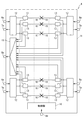
- FIG. 2 is a block diagram of the antenna system 4.
- the antenna system 4 includes the casing 11 and a plurality of antenna elements 10, a plurality of distribution / combiners 12, a plurality of signal processing modules 13, a control unit 14, and a combiner 15.
- the distribution synthesizers 12 are provided in the casing 11 in the same number as the connection ports 6a (7a). Each distribution synthesizer 12 is connected to a set of connection ports 6 a and 7 a and is connected to a plurality of signal processing modules 13.
- the plurality of signal processing modules 13 are respectively connected to the antenna elements 10 having the same polarization direction.
- the antenna system 4 of this embodiment has a 4-branch MIMO function.
- the distribution synthesizer 12 distributes the radio frequency transmission signal given from the RRH 3 via the connection port 6 a to each of the plurality of signal processing modules 13, and gives the distributed transmission signal to each signal processing module 13.
- the distribution synthesizer 12 synthesizes reception signals received as radio signals by the plurality of antenna elements 10 and provides the synthesized radio frequency reception signal to the RRH 3 from the connection port 7a.
- FIG. 3 is a block diagram of the signal processing module 13.
- the signal processing module 13 includes two duplexers 21 and 22 and a signal processing unit 23.
- the signal processing unit 23 includes a first phase shifter 27 and a first amplifier 28 in order to process a radio frequency signal (radio signal) transmitted by the antenna element 10 connected to the signal processing module 13.
- the signal processing unit 23 includes a second phase shifter 29 and a second amplifier 30 in order to process a radio signal received by the antenna element 10 connected to the signal processing module 13.
- One duplexer 21 is connected to the first phase shifter 27 and the second phase shifter 29 and is also connected to the distribution synthesizer 12 (see FIG. 2).
- the other duplexer 22 is connected to the first amplifier 28 and the second amplifier 30 and to the antenna element 10 (see FIG. 2).
- the duplexer 21 provides the first phase shifter 27 with the radio signal (radio frequency transmission signal) input from the distribution synthesizer 12.
- the first phase shifter 27 adjusts the phase of the transmission signal given from the duplexer 21.
- the first phase shifter 27 provides the first amplifier 28 with the transmission signal whose phase has been adjusted.
- the first amplifier 28 amplifies the power of the transmission signal given from the first phase shifter 27 and passes the amplified transmission signal to the duplexer 22 through the signal extraction unit 25.
- the duplexer 22 outputs the transmission signal given from the first amplifier 28 to the antenna element 10.
- a radio signal (radio frequency received signal) received by the antenna element 10 is given to the duplexer 22.
- the duplexer 22 provides the input received signal to the second amplifier 30.
- the second amplifier 30 amplifies the power of the input reception signal and supplies the second phase shifter 29 with the transmission signal whose power has been amplified.
- the second phase shifter 29 adjusts the phase of the reception signal supplied from the second amplifier 30 and supplies the reception signal with the adjusted phase to the duplexer 21.
- the duplexer 21 outputs the received signal given from the second phase shifter 29 to the distribution synthesizer 12.
- each signal processing module 13 functions as an active antenna that can perform processing such as phase adjustment and power amplification on the transmission / reception signals transmitted and received by the plurality of antenna elements 10 for each antenna element 10. Processing can be performed.
- the signal processing module 13 further includes a signal extraction unit 25 and a switch 26.
- the signal extraction unit 25 is composed of, for example, a directional coupler, and is provided between the first amplifier 28 and the duplexer 22.
- the signal extraction unit 25 extracts a transmission signal output from the signal processing unit 23 toward the antenna element 10. Specifically, the signal extraction unit 25 extracts a transmission signal whose power is amplified by the first amplifier 28 of the signal processing unit 23, and provides the transmission signal to the synthesizer 15 (see FIG. 2).
- the switch 26 is provided on a path connecting the signal extraction unit 25 and the combiner 15, and connects and disconnects the path.
- the switch 26 of the present embodiment is composed of, for example, a multi-port high-frequency switch, and has an a contact, a b contact, and a c contact.
- the switch 26 is controlled by the control unit 14 (see FIG. 2) so as to be in one of an off state in which the a contact is connected to the b contact and an on state in which the a contact is connected to the c contact. Is done.
- the contact a of the switch 26 is connected to the signal extraction unit 25. Further, for example, a terminator 31 is connected to the b contact of the switch 26, and the c contact of the switch 26 is connected to the synthesizer 15 (see FIG. 2).
- the control unit 14 turns off the switch 26 (a contact is connected to the b contact) and terminates the signal extraction unit 25. Connected to the device 31.
- the control unit 14 switches on the switch 26 (a state where the a contact is connected to the c contact).
- the signal extraction unit 25 is connected to the combiner 15.
- the control unit 14 is provided in the housing 11 and has a function of individually controlling the switches 26 of the signal processing modules 13.
- the control unit 14 is connected to a control port 8 a provided on the bottom surface 11 a of the housing 11.
- the control port 8a is a port compliant with, for example, Ethernet (registered trademark), and is connected to a control cable 8 extending from an external device 50 such as a measuring instrument or a notebook personal computer.
- Control information for controlling the switch 26 of one or a plurality of signal processing modules 13 is input to the control unit 14 from the external device 50 through the control cable 8 and the control port 8a. Accordingly, the control unit 14 of the present embodiment individually controls the switch 26 of each signal processing module 13 based on the control information input from the external device 50 by connecting the control cable 8 to the control port 8a. It is like that.
- the synthesizer 15 is provided in the housing 11 and has a function of synthesizing transmission signals extracted by the signal extraction units 25 of two or more different signal processing modules 13. Only one synthesizer 15 according to this embodiment is provided in the casing 11 and synthesizes transmission signals extracted from all the signal processing modules 13.
- the synthesizer 15 is connected to a single inspection port 9a provided on the bottom surface (outer surface) 11a of the casing 11, and outputs the synthesized transmission signal to the inspection port 9a. Further, when the transmission signal extracted from the single signal processing module 13 is given, the synthesizer 15 outputs the transmission signal as it is to the inspection port 9a.
- the inspection port 9a is a port compliant with, for example, Ethernet (registered trademark), and is connected to an inspection cable 9 extending from the external device 50 (see FIG. 1).
- Ethernet registered trademark
- the inspection port that can output the transmission signal to the antenna element 10 extracted by the signal extraction unit 25 to the outside in the casing 11 in which the antenna element 10 and the signal processing unit 23 are accommodated. Since 9a is provided, the signal processing unit 23 can be easily accessed from the outside of the housing 11 by connecting the inspection cable 9 of the external device 50 to the inspection port 9a. Thereby, the inspection work of the antenna system 4 can be performed easily.
- a switch 26 for connecting / disconnecting the path is provided on a path connecting each signal extraction unit 25 and the combiner 15. For this reason, by turning on only one of the switches 26 and turning off all the other switches, the transmission signals taken out from the signal take-out sections 25 are sent from the inspection port 9a to the outside via the synthesizer 15. Can be output.
- FIG. 4 is a block diagram of an antenna system 4 according to the second embodiment of the present invention.
- the main difference between the antenna system 4 of the present embodiment and the first embodiment is that the synthesizer 15 (see FIG. 2) is not provided.
- the antenna system 4 of this embodiment includes the same number of inspection ports 9 a as the signal processing module 13. Thereby, the transmission signal taken out from each signal processing module 13 is individually output to the outside from the corresponding inspection port 9a. Since the other structure of this embodiment is the same as that of 1st Embodiment, description is abbreviate
- each signal processing unit 23 can be easily accessed from the outside of the housing 11. be able to.
- the switch 26 (see FIG. 3) is provided in the signal processing module 13, but a terminator may be detachably connected to each inspection port 9a instead of the switch 26. In this case, when connecting the inspection cable 9 to the inspection port 9a, it is only necessary to remove the terminator and connect the inspection cable 9.
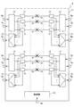
- FIG. 5 is a block diagram of an antenna system 4 according to the third embodiment of the present invention.
- the main difference between the antenna system 4 of the present embodiment and the first embodiment is that a plurality of combiners 15 and a plurality of inspection ports 9a are provided.
- the antenna system 4 of the present embodiment includes the same number (four) of combiners 15 and inspection ports 9a as the number of MIMO branches.
- Each synthesizer 15 synthesizes the transmission signals extracted from the signal extraction units 25 of the plurality of signal processing modules 13 constituting one branch.
- Each combiner 15 is connected to a single inspection port 9a, and outputs the combined transmission signal to the inspection port 9a.
- Each synthesizer 15 receives the transmission signal extracted from any one of the signal processing modules 13 among the plurality of signal processing modules 13, and the inspection signal 9a corresponding to the transmission signal as it is. Output to. Since the other structure of this embodiment is the same as that of 1st Embodiment, description is abbreviate
- the antenna system 4 of the present embodiment includes a combiner 15 and an inspection port 9a for each MIMO branch.
- the combiner 15 and an inspection port are provided for each of two orthogonal polarization directions of the antenna element 10.
- a port 9a may be provided.
- a plurality of signal processing modules 13 arranged on the right side and the left side are output to the antenna elements 10 having the same polarization direction. For this reason, the transmission signals extracted from the plurality of signal processing modules 13 on the right side are combined by one synthesizer 15, and the transmission signals extracted from the plurality of signal processing modules 13 on the left side are combined by one other synthesizer 15. You may synthesize.
- FIG. 6 is a block diagram showing a part of the base station apparatus 1 including the antenna system 4 according to the fourth embodiment of the present invention.
- the main difference between the antenna system 4 of the present embodiment and the first embodiment is that the upstream end of the control cable 8 is connected to the RRH 3.
- the control cable 8 extending from the RRH 3 is connected to the control port 8 a of the housing 11.
- the RRH 3 controls information for controlling the switch 26 of one or a plurality of signal processing modules 13 with respect to the control unit 14 (see FIG. 2) in the housing 11 via the control cable 8 and the control port 8a.
- the control part 14 of this embodiment controls the switch 26 of each signal processing module 13 with the control information input from RRH3 by connecting the control cable 8 to the control port 8a. Since the other structure of this embodiment is the same as that of 1st Embodiment, description is abbreviate
- the antenna system 4 according to the fourth embodiment also has the same effects as the first embodiment.
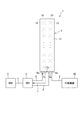
- FIG. 7 is a block diagram showing a part of the base station apparatus 1 including the active antenna system 4 according to the fifth embodiment of the present invention.
- the antenna system 4 of the present embodiment is a modification of the fourth embodiment, and is mainly different from the fourth embodiment in that the antenna system 4 and the BBU 2 are directly connected without using the RRH 3. is there.
- the BBU 2 of the present embodiment is connected to a connection port 17 provided in the housing 11 of the antenna system 4 via a signal transmission path 5 such as an optical fiber cable.
- the connection port 17 is connected to an interface unit (not shown) for transmitting and receiving a frame conforming to the CPRI in the housing 11.
- the BBU 2 gives a transmission baseband signal obtained by modulating transmission data given from an upper network (not shown) to the antenna system 4 via the signal transmission path 5. Further, the BBU 2 acquires a reception baseband signal (I / Q signal) that is a digital signal given from the antenna system 4 via the signal transmission path 5, and performs digital demodulation processing on the reception baseband signal. And has a function of generating received data. The BBU 2 gives received data obtained by demodulating the received baseband signal to the upper network.
- the BBU 2 gives control information for controlling the switches 26 of the one or more signal processing modules 13 to the control unit 14 (see FIG. 2) in the housing 11 via the signal transmission path 5.
- the control part 14 of this embodiment controls the switch 26 of each signal processing module 13 with the control information input from BBU2. Since the other structure of this embodiment is the same as that of 1st Embodiment, description is abbreviate
- the antenna system 4 according to the fifth embodiment also has the same effects as the first embodiment.
- Base station device Baseband unit (BBU) 3 Remote Radio Head (RRH) DESCRIPTION OF SYMBOLS 4 Active antenna system 5 Signal transmission path 6 Coaxial cable 6a Connection port 7 Coaxial cable 7a Connection port 8 Control cable 8a Connection port 9 Inspection cable 9a Inspection port 10 Antenna element 11 Case 11a Bottom surface 12 Divider / Synthesizer 13 Signal processing Module 14 Control unit 15 Synthesizer 17 Connection port 21 Duplexer 22 Duplexer 23 Signal processing unit 25 Signal extraction unit 26 Switch 27 First phase shifter 28 First amplifier 29 Second phase shifter 30 Second amplifier 31 Terminator 50 External device
Abstract
Provided is an active antenna system that comprises a plurality of antenna elements, a plurality of signal processing units that perform processing on radio signals that are to be respectively transmitted by the plurality of antenna elements, and a casing that accommodates the plurality of antenna elements and the plurality of signal processing units, wherein the active antenna system is provided with the following: a plurality of signal obtaining units that obtain from the respective signal processing units transmission signals that are to be output to the corresponding antenna elements; and an inspection port that is provided in the casing and can output the obtained transmission signals to outside the casing.
Description
本発明は、アクティブアンテナシステムに関する。
本出願は、2016年3月18日出願の日本出願第2016-055414号に基づく優先権を主張し、前記日本出願に記載された全ての記載内容を援用するものである。 The present invention relates to an active antenna system.
This application claims priority based on Japanese Patent Application No. 2016-055414 filed on Mar. 18, 2016, and incorporates all the content described in the above Japanese application.
従来から、携帯電話等の無線通信システムに用いられる基地局装置では、無線周波数の信号を処理する無線送受信部(RRH;Remote Radio Head)と、ベースバンド信号に関する処理を行うベースバンド信号処理部(BBU;Base Band Unit)とを分離した構成が採用されている。
Conventionally, in a base station apparatus used in a wireless communication system such as a mobile phone, a radio transmission / reception unit (RRH; Remote Radio Head) that processes a signal of a radio frequency and a baseband signal processing unit that performs processing related to a baseband signal ( The structure which isolate | separated BBU; Base | Band | Unit | Unit) is employ | adopted.
RRHには、屋外に設置されたアンテナシステムが同軸ケーブル等を介して接続される。RRHと、アンテナシステムとの間においては、アンテナシステムが送受信する無線周波数の送受信信号が同軸ケーブル等を介して伝送される。
また、RRHとBBUとの間は光ファイバケーブル等によって接続され、両者の間においては光通信等によってデジタルのベースバンド信号が伝送される。 An antenna system installed outdoors is connected to the RRH via a coaxial cable or the like. A radio frequency transmission / reception signal transmitted / received by the antenna system is transmitted between the RRH and the antenna system via a coaxial cable or the like.
The RRH and the BBU are connected by an optical fiber cable or the like, and a digital baseband signal is transmitted between the two by optical communication or the like.
通常、BBUは屋内に設置され、RRHは屋外のアンテナシステムの直下に設置される。このように、基地局装置の送受信機能をBBUとRRHとに分離し、RRHを当該アンテナシステムの近傍に設置することで、アンテナシステムとRRHとを接続する同軸ケーブルの長さをできるだけ短くし、同軸ケーブルによって無線周波数の送受信信号が減衰されるのを抑制している。
Normally, BBU is installed indoors and RRH is installed directly under the outdoor antenna system. Thus, by separating the transmission / reception function of the base station device into BBU and RRH, and installing RRH in the vicinity of the antenna system, the length of the coaxial cable connecting the antenna system and RRH is made as short as possible, The coaxial cable suppresses attenuation of radio frequency transmission / reception signals.
そして、RRHには、Ethernet(登録商標)やRC232C等に準拠した接続方法により、外部と通信するためのケーブルが接続される保守ポートが設けられている(例えば、特許文献1参照)。これにより、例えば、保守ポートの1つとして外部の測定器とケーブルを介して接続するポートを用意することで、RRHの無線性能を調べて電波法等を遵守していることや、内部の各機器が正常に動作していること等を確認する点検作業が行えるようになっている。以下、このポートを点検用ポートと呼ぶ。
The RRH is provided with a maintenance port to which a cable for communication with the outside is connected by a connection method compliant with Ethernet (registered trademark), RC232C, or the like (see, for example, Patent Document 1). Thus, for example, by preparing a port connected to an external measuring instrument as a maintenance port through a cable, the radio performance of the RRH is examined and the radio wave law is observed, Inspection work to confirm that the equipment is operating normally can be performed. Hereinafter, this port is referred to as an inspection port.
本開示のアクティブアンテナシステムは、複数のアンテナ素子と、前記複数のアンテナ素子それぞれにより送信される無線信号の処理を行う複数の信号処理部と、前記複数のアンテナ素子及び前記複数の信号処理部が収容された筐体と、を備えたアクティブアンテナシステムであって、前記各信号処理部から、対応する前記アンテナ素子に出力される送信信号を取り出す複数の信号取出部と、前記筐体に設けられ、取り出された前記送信信号を前記筐体の外部に出力可能な点検用ポートと、を備えるアクティブアンテナシステムである。
The active antenna system according to the present disclosure includes a plurality of antenna elements, a plurality of signal processing units that process radio signals transmitted by the plurality of antenna elements, and the plurality of antenna elements and the plurality of signal processing units. A plurality of signal extraction units that extract transmission signals output to the corresponding antenna elements from each of the signal processing units, and provided in the case. And an inspection port capable of outputting the extracted transmission signal to the outside of the housing.
[本開示が解決しようとする課題]
近年、無線通信システムにおいては、スマートフォン等の普及により、通信エリアの拡大や通信容量の拡張に対する要求が高まっており、RRHとしての機能を内蔵したアクティブアンテナシステムの基地局装置への適用が提案されている。
アクティブアンテナシステムは、複数のアンテナ素子と、複数のアンテナ素子それぞれに対応して設けられた複数の無線送受信部(従来のRRHに相当)とを備えている。このため、アンテナ素子ごとに送受信される無線信号を制御することができ制御性に優れており、この優れた制御性を利用して通信環境を向上し得る新たなサービスの提供が可能となる。 [Problems to be solved by the present disclosure]
In recent years, with the spread of smartphones and the like in wireless communication systems, there has been a growing demand for expansion of communication areas and expansion of communication capacity, and application of active antenna systems incorporating RRH functions to base station devices has been proposed. ing.
The active antenna system includes a plurality of antenna elements and a plurality of radio transmission / reception units (corresponding to conventional RRHs) provided corresponding to the plurality of antenna elements. For this reason, the radio signal transmitted / received for each antenna element can be controlled, and the controllability is excellent, and it is possible to provide a new service that can improve the communication environment using this excellent controllability.
しかし、アクティブアンテナシステムでは、無線送受信部とアンテナ素子とが筐体内で一体化された構造となる。このため、従来のRRHと同様に、無線送受信部の出力部で無線信号の品質を確認しようとすると、点検作業時に筐体の外部から無線送受信部の出力部に容易にアクセスすることができないという問題が生じる。
However, the active antenna system has a structure in which the wireless transmission / reception unit and the antenna element are integrated in the casing. For this reason, as with conventional RRHs, if the quality of the radio signal is confirmed at the output unit of the radio transmission / reception unit, the output unit of the radio transmission / reception unit cannot be easily accessed from the outside of the housing during inspection work. Problems arise.
また、複数の無線送受信部それぞれに設けた点検用ポートに同軸ケーブルを接続し、各無線送受信部から信号を取り出して点検作業を行う場合、多数の点検用ポート毎に同軸ケーブルを接続する作業が必要となるため、作業性が著しく困難となる。また、アンテナ素子毎の無線送受信部の単体の出力ではなく、合成したアンテナ素子全体としての出力を確認したいというニーズもある。
In addition, when a coaxial cable is connected to an inspection port provided in each of a plurality of wireless transmission / reception units and a signal is taken out from each wireless transmission / reception unit to perform an inspection operation, an operation of connecting the coaxial cable to each of a large number of inspection ports Therefore, workability becomes extremely difficult. There is also a need to check the output of the combined antenna element as a whole, not the output of a single wireless transmission / reception unit for each antenna element.
そこで、点検作業を簡単に行うことができるアクティブアンテナシステムを提供することを目的とする。
Therefore, an object of the present invention is to provide an active antenna system that can easily perform inspection work.
[本開示の効果]
本開示によれば、点検作業を簡単に行うことができる。 [Effects of the present disclosure]
According to the present disclosure, the inspection work can be easily performed.
本開示によれば、点検作業を簡単に行うことができる。 [Effects of the present disclosure]
According to the present disclosure, the inspection work can be easily performed.
[本発明の実施形態の説明]
最初に本発明の実施形態の内容を列記して説明する。
(1)本発明の実施形態に係るアクティブアンテナシステムは、複数のアンテナ素子と、前記複数のアンテナ素子それぞれにより送信される無線信号の処理を行う複数の信号処理部と、前記複数のアンテナ素子及び前記複数の信号処理部が収容された筐体と、を備えたアクティブアンテナシステムであって、前記各信号処理部から、対応する前記アンテナ素子に出力される送信信号を取り出す複数の信号取出部と、前記筐体に設けられ、取り出された前記送信信号を前記筐体の外部に出力可能な点検用ポートと、を備える。 [Description of Embodiment of the Present Invention]
First, the contents of the embodiment of the present invention will be listed and described.
(1) An active antenna system according to an embodiment of the present invention includes a plurality of antenna elements, a plurality of signal processing units that process radio signals transmitted by the plurality of antenna elements, the plurality of antenna elements, An active antenna system including a plurality of signal processing units, and a plurality of signal extraction units that extract transmission signals output to the corresponding antenna elements from the signal processing units. An inspection port provided in the casing and capable of outputting the extracted transmission signal to the outside of the casing.
上記アクティブアンテナシステムによれば、アンテナ素子及び信号処理部が収容された筐体に、信号取出部が取り出したアンテナ素子への送信信号を外部に出力可能な点検用ポートが設けられているので、点検用ポートに測定器等の外部機器のケーブルを接続することで、筐体の外部から信号処理部に容易にアクセスすることができる。これにより、アクティブアンテナシステムの点検作業を容易に行うことができる。
According to the above active antenna system, the inspection port that can output the transmission signal to the antenna element taken out by the signal extraction unit is provided in the housing in which the antenna element and the signal processing unit are accommodated. By connecting a cable of an external device such as a measuring instrument to the inspection port, the signal processing unit can be easily accessed from the outside of the housing. Thereby, the inspection work of an active antenna system can be performed easily.
(2)前記アクティブアンテナシステムは、互いに異なる前記信号取出部により取り出された2以上の前記送信信号を合成して前記点検用ポートに出力する合成器をさらに備えるのが好ましい。
この場合、互いに異なる信号取出部により取り出された2以上の送信信号は、合成器により合成されて点検用ポートに出力されるので、2以上のアンテナ素子から放射した実際の無線信号と同等の信号を、点検用ポートから外部に出力して確認することができる。 (2) It is preferable that the active antenna system further includes a combiner that combines two or more transmission signals extracted by the signal extraction units different from each other and outputs the combined signals to the inspection port.
In this case, since two or more transmission signals extracted by different signal extraction units are synthesized by the combiner and output to the inspection port, a signal equivalent to an actual radio signal radiated from the two or more antenna elements. Can be output from the inspection port to the outside for confirmation.
(3)前記アクティブアンテナシステムは、前記各信号取出部と前記合成器とを接続する経路上にそれぞれ設けられ、当該経路を断接する複数のスイッチをさらに備えるのが好ましい。
この場合、いずれか1つのスイッチのみをオンとし、他のスイッチをすべてオフとすることにより、各信号取出部から取り出された送信信号を合成器を介して点検用ポートから外部に出力することができる。これにより、故障している信号処理部の特定や、各信号処理部の経年劣化状況を容易に確認することができる。また、2以上の所定数のスイッチをオンとし、他のスイッチをオフとすることにより、任意の所定数の送信信号を合成器により合成して点検用ポートから外部に出力することも可能となる。 (3) It is preferable that the active antenna system further includes a plurality of switches provided on paths connecting the signal extraction units and the combiner, and connecting and disconnecting the paths.
In this case, by turning on only one of the switches and turning off all of the other switches, the transmission signal extracted from each signal extraction unit can be output to the outside from the inspection port via the combiner. it can. As a result, it is possible to easily identify the faulty signal processing unit and the aged deterioration state of each signal processing unit. In addition, by turning on a predetermined number of switches of 2 or more and turning off the other switches, it is possible to synthesize an arbitrary predetermined number of transmission signals by a synthesizer and output it from the inspection port to the outside. .
(4)前記アクティブアンテナシステムは、前記複数のスイッチを個別に制御する制御部をさらに備えるのが好ましい。
この場合、制御部により複数のスイッチを個別に制御することで、点検用ポートから外部に出力する信号を容易に変更することができる。 (4) It is preferable that the active antenna system further includes a control unit that individually controls the plurality of switches.
In this case, the signal output from the inspection port to the outside can be easily changed by individually controlling the plurality of switches by the control unit.
[本発明の実施形態の詳細]
以下、本発明の実施形態について添付図面に基づき詳細に説明する。なお、以下に記載する実施形態の少なくとも一部を任意に組み合わせてもよい。
[第1実施形態]
<基地局装置について>
図1は、本発明の第1実施形態に係るアクティブアンテナシステムを備えた基地局装置の一部を示すブロック図である。基地局装置1は、例えば、LTE(Long Term Evolution)が適用される携帯電話用の無線通信システムにおいて基地局装置として用いられるものであり、携帯電話等の複数の移動端末(図示省略)とMIMO(Multiple Input Multiple Output)伝送による無線通信を行う機能を有している。 [Details of the embodiment of the present invention]
Hereinafter, embodiments of the present invention will be described in detail with reference to the accompanying drawings. In addition, you may combine arbitrarily at least one part of embodiment described below.
[First Embodiment]
<About base station equipment>
FIG. 1 is a block diagram illustrating a part of a base station apparatus including an active antenna system according to the first embodiment of the present invention. The base station apparatus 1 is used as a base station apparatus in a wireless communication system for mobile phones to which LTE (Long Term Evolution) is applied, for example, and is connected to a plurality of mobile terminals (not shown) such as mobile phones and MIMO. (Multiple Input Multiple Output) It has a function of performing wireless communication by transmission.
基地局装置1は、ベースバンドユニット(BBU)2と、リモートラジオヘッド(RRH)3と、アクティブアンテナシステム4(以下、単にアンテナシステム4ともいう)とを備えている。
BBU2は、光ファイバケーブル等の信号伝送路5を介してRRH3に接続されており、RRH3との間でCPRI(Common Public Radio Interface)に準拠したフレーム(CPRIフレーム)の送受信を行う機能を有している。
具体的には、BBU2は、RRH3から信号伝送路5を介してデジタル信号である受信ベースバンド信号(I/Q信号)を取得する。そして、BBU2は、受信ベースバンド信号に対してデジタル復調処理を行うことで受信データを生成する機能を有しており、生成した受信データを上位ネットワークに与える。 The base station apparatus 1 includes a baseband unit (BBU) 2, a remote radio head (RRH) 3, and an active antenna system 4 (hereinafter also simply referred to as an antenna system 4).
The BBU 2 is connected to the RRH 3 via asignal transmission line 5 such as an optical fiber cable, and has a function of transmitting and receiving a frame (CPRI frame) compliant with the CPRI (Common Public Radio Interface) to the RRH 3. ing.
Specifically, the BBU 2 acquires a reception baseband signal (I / Q signal) that is a digital signal from the RRH 3 via thesignal transmission path 5. And BBU2 has a function which produces | generates reception data by performing a digital demodulation process with respect to a reception baseband signal, and gives the produced | generated reception data to a high-order network.
BBU2は、光ファイバケーブル等の信号伝送路5を介してRRH3に接続されており、RRH3との間でCPRI(Common Public Radio Interface)に準拠したフレーム(CPRIフレーム)の送受信を行う機能を有している。
具体的には、BBU2は、RRH3から信号伝送路5を介してデジタル信号である受信ベースバンド信号(I/Q信号)を取得する。そして、BBU2は、受信ベースバンド信号に対してデジタル復調処理を行うことで受信データを生成する機能を有しており、生成した受信データを上位ネットワークに与える。 The base station apparatus 1 includes a baseband unit (BBU) 2, a remote radio head (RRH) 3, and an active antenna system 4 (hereinafter also simply referred to as an antenna system 4).
The BBU 2 is connected to the RRH 3 via a
Specifically, the BBU 2 acquires a reception baseband signal (I / Q signal) that is a digital signal from the RRH 3 via the
BBU2は、上位ネットワーク(図示せず)から与えられる送信データに対してデジタル変調処理を行うことで送信ベースバンド信号を生成する機能を有している。BBU2は、送信データを変調して得たデジタルの送信ベースバンド信号を信号伝送路5を介してRRH3に与える。
The BBU 2 has a function of generating a transmission baseband signal by performing digital modulation processing on transmission data given from an upper network (not shown). The BBU 2 gives a digital transmission baseband signal obtained by modulating transmission data to the RRH 3 via the signal transmission path 5.
RRH3は、当該RRH3から延びる同軸ケーブル6,7を、アンテナシステム4の筐体11に設けられた接続ポート6a,7aにそれぞれ接続することでアンテナシステム4に接続されており、送受信信号を送受信する際の信号処理を行う。なお、本実施形態の接続ポート6a,7aは、図1では図示を一部省略しているが、筐体11の底面11aにそれぞれ複数(例えば4個)設けられており、各接続ポート6a,7aには、RRH3から延びる同数の同軸ケーブル6,7がそれぞれ接続されている。
The RRH 3 is connected to the antenna system 4 by connecting the coaxial cables 6 and 7 extending from the RRH 3 to connection ports 6a and 7a provided in the casing 11 of the antenna system 4, and transmits and receives transmission / reception signals. Signal processing. Although a part of the connection ports 6a and 7a of this embodiment is not shown in FIG. 1, a plurality of (for example, four) connection ports 6a and 7a are provided on the bottom surface 11a of the housing 11, respectively. The same number of coaxial cables 6 and 7 extending from the RRH 3 are respectively connected to 7a.
RRH3は、BBU2から与えられる送信ベースバンド信号に対して各種信号処理を行うことでアナログの無線周波数の信号に変換する機能を有している。そして、RRH3は、変換したアナログの無線周波数の送信信号を同軸ケーブル6を介してアンテナシステム4に与える。
RRH3は、同軸ケーブル7を介してアンテナシステム4から与えられる無線周波数の受信信号に対して各種信号処理を行うことでデジタルの受信信号に変換する機能を有している。RRH3は、変換したデジタルの受信信号をBBU2に与える。 The RRH 3 has a function of converting it into an analog radio frequency signal by performing various signal processing on the transmission baseband signal given from the BBU 2. The RRH 3 supplies the converted analog radio frequency transmission signal to the antenna system 4 via the coaxial cable 6.
The RRH 3 has a function of converting a radio frequency reception signal supplied from the antenna system 4 through thecoaxial cable 7 into a digital reception signal by performing various signal processing. The RRH 3 gives the converted digital reception signal to the BBU 2.
RRH3は、同軸ケーブル7を介してアンテナシステム4から与えられる無線周波数の受信信号に対して各種信号処理を行うことでデジタルの受信信号に変換する機能を有している。RRH3は、変換したデジタルの受信信号をBBU2に与える。 The RRH 3 has a function of converting it into an analog radio frequency signal by performing various signal processing on the transmission baseband signal given from the BBU 2. The RRH 3 supplies the converted analog radio frequency transmission signal to the antenna system 4 via the coaxial cable 6.
The RRH 3 has a function of converting a radio frequency reception signal supplied from the antenna system 4 through the
アンテナシステム4は、RRH3よりも高所(ビルの屋上や鉄塔上など)に設置されている。アンテナシステム4は、筐体11の内部に収納された、無線周波数の信号を送受信する複数のアンテナ素子10を備えており、基地局装置1が移動端末との間で無線通信を行う際に、当該無線通信に係る無線信号を送受信する機能を有している。本実施形態のアンテナシステム4は、互いに直交する偏波方向となる2個のアンテナ素子10を1組として、4×N個(Nは1以上の整数)のアンテナ素子10を備えている。
The antenna system 4 is installed higher than the RRH 3 (such as on the roof of a building or on a steel tower). The antenna system 4 includes a plurality of antenna elements 10 housed in a housing 11 for transmitting and receiving radio frequency signals. When the base station apparatus 1 performs wireless communication with a mobile terminal, It has a function of transmitting and receiving wireless signals related to the wireless communication. The antenna system 4 of the present embodiment includes 4 × N antenna elements 10 (N is an integer equal to or greater than 1), with two antenna elements 10 having polarization directions orthogonal to each other as a set.
アンテナシステム4は、RRH3から与えられる無線周波数の送信信号を、複数のアンテナ素子10それぞれに対応して分配し、各アンテナ素子10から無線信号として送信する。また、アンテナシステム4は、複数のアンテナ素子10が無線信号として受信する無線周波数の受信信号を合成し、合成した無線周波数の信号をRRH3に与える。
このように、基地局装置1は、デジタルの送信信号を無線周波数の信号に変換して移動端末に送信するとともに、移動端末が送信した無線周波数の信号を受信し、移動端末からの受信信号を取得する。 The antenna system 4 distributes a radio frequency transmission signal provided from the RRH 3 corresponding to each of the plurality ofantenna elements 10 and transmits the radio signals from the antenna elements 10 as radio signals. In addition, the antenna system 4 synthesizes radio frequency reception signals received by the plurality of antenna elements 10 as radio signals, and gives the synthesized radio frequency signal to the RRH 3.
In this way, the base station apparatus 1 converts a digital transmission signal into a radio frequency signal and transmits it to the mobile terminal, receives the radio frequency signal transmitted by the mobile terminal, and receives the received signal from the mobile terminal. get.
このように、基地局装置1は、デジタルの送信信号を無線周波数の信号に変換して移動端末に送信するとともに、移動端末が送信した無線周波数の信号を受信し、移動端末からの受信信号を取得する。 The antenna system 4 distributes a radio frequency transmission signal provided from the RRH 3 corresponding to each of the plurality of
In this way, the base station apparatus 1 converts a digital transmission signal into a radio frequency signal and transmits it to the mobile terminal, receives the radio frequency signal transmitted by the mobile terminal, and receives the received signal from the mobile terminal. get.
<アンテナシステムについて>
図2は、アンテナシステム4のブロック図である。アンテナシステム4は、上記筐体11及び複数のアンテナ素子10と、複数の分配合成器12と、複数の信号処理モジュール13と、制御部14と、合成器15とを有している。
分配合成器12は、筐体11内において接続ポート6a(7a)と同数設けられている。各分配合成器12は、1組の接続ポート6a,7aにそれぞれ接続されているとともに、複数の信号処理モジュール13に接続されている。これら複数の信号処理モジュール13は、偏波方向が同一のアンテナ素子10にそれぞれ接続されている。 <About the antenna system>
FIG. 2 is a block diagram of the antenna system 4. The antenna system 4 includes thecasing 11 and a plurality of antenna elements 10, a plurality of distribution / combiners 12, a plurality of signal processing modules 13, a control unit 14, and a combiner 15.
Thedistribution synthesizers 12 are provided in the casing 11 in the same number as the connection ports 6a (7a). Each distribution synthesizer 12 is connected to a set of connection ports 6 a and 7 a and is connected to a plurality of signal processing modules 13. The plurality of signal processing modules 13 are respectively connected to the antenna elements 10 having the same polarization direction.
図2は、アンテナシステム4のブロック図である。アンテナシステム4は、上記筐体11及び複数のアンテナ素子10と、複数の分配合成器12と、複数の信号処理モジュール13と、制御部14と、合成器15とを有している。
分配合成器12は、筐体11内において接続ポート6a(7a)と同数設けられている。各分配合成器12は、1組の接続ポート6a,7aにそれぞれ接続されているとともに、複数の信号処理モジュール13に接続されている。これら複数の信号処理モジュール13は、偏波方向が同一のアンテナ素子10にそれぞれ接続されている。 <About the antenna system>
FIG. 2 is a block diagram of the antenna system 4. The antenna system 4 includes the
The
以上の構成により、1個の分配合成器12と、この分配合成器12が接続されている複数の信号処理モジュール13と、これら複数の信号処理モジュール13がそれぞれ接続される複数のアンテナ素子とが1ブランチを構成している。したがって、本実施形態のアンテナシステム4は、4ブランチMIMOの機能を有している。
With the above configuration, one distribution synthesizer 12, a plurality of signal processing modules 13 to which the distribution synthesizer 12 is connected, and a plurality of antenna elements to which the plurality of signal processing modules 13 are respectively connected. One branch is configured. Therefore, the antenna system 4 of this embodiment has a 4-branch MIMO function.
分配合成器12は、RRH3から接続ポート6aを介して与えられる無線周波数の送信信号を複数の信号処理モジュール13それぞれに対応して分配し、分配した送信信号を各信号処理モジュール13に与える。
また、分配合成器12は、複数のアンテナ素子10が無線信号として受信した受信信号を合成し、合成した無線周波数の受信信号を接続ポート7aからRRH3に与える。 Thedistribution synthesizer 12 distributes the radio frequency transmission signal given from the RRH 3 via the connection port 6 a to each of the plurality of signal processing modules 13, and gives the distributed transmission signal to each signal processing module 13.
Thedistribution synthesizer 12 synthesizes reception signals received as radio signals by the plurality of antenna elements 10 and provides the synthesized radio frequency reception signal to the RRH 3 from the connection port 7a.
また、分配合成器12は、複数のアンテナ素子10が無線信号として受信した受信信号を合成し、合成した無線周波数の受信信号を接続ポート7aからRRH3に与える。 The
The
<信号処理モジュールについて>
図3は、信号処理モジュール13のブロック構成図である。信号処理モジュール13は、2つの共用器21,22と、信号処理部23とを備えている。
信号処理部23は、信号処理モジュール13に接続されているアンテナ素子10により送信される無線周波数の信号(無線信号)の処理を行うために、第1移相器27と第1増幅器28とを有する。また、信号処理部23は、信号処理モジュール13に接続されているアンテナ素子10が受信した無線信号の処理を行うために、第2移相器29と第2増幅器30とを有する。 <Signal processing module>
FIG. 3 is a block diagram of thesignal processing module 13. The signal processing module 13 includes two duplexers 21 and 22 and a signal processing unit 23.
Thesignal processing unit 23 includes a first phase shifter 27 and a first amplifier 28 in order to process a radio frequency signal (radio signal) transmitted by the antenna element 10 connected to the signal processing module 13. Have. In addition, the signal processing unit 23 includes a second phase shifter 29 and a second amplifier 30 in order to process a radio signal received by the antenna element 10 connected to the signal processing module 13.
図3は、信号処理モジュール13のブロック構成図である。信号処理モジュール13は、2つの共用器21,22と、信号処理部23とを備えている。
信号処理部23は、信号処理モジュール13に接続されているアンテナ素子10により送信される無線周波数の信号(無線信号)の処理を行うために、第1移相器27と第1増幅器28とを有する。また、信号処理部23は、信号処理モジュール13に接続されているアンテナ素子10が受信した無線信号の処理を行うために、第2移相器29と第2増幅器30とを有する。 <Signal processing module>
FIG. 3 is a block diagram of the
The
一方の共用器21は、第1移相器27及び第2移相器29に接続されているとともに、分配合成器12(図2参照)に接続されている。他方の共用器22は、第1増幅器28及び第2増幅器30に接続されているとともに、アンテナ素子10(図2参照)に接続されている。
One duplexer 21 is connected to the first phase shifter 27 and the second phase shifter 29 and is also connected to the distribution synthesizer 12 (see FIG. 2). The other duplexer 22 is connected to the first amplifier 28 and the second amplifier 30 and to the antenna element 10 (see FIG. 2).
共用器21は、分配合成器12から入力された無線信号(無線周波数の送信信号)を第1移相器27に与える。第1移相器27は、共用器21から与えられた送信信号の位相を調整する。第1移相器27は、位相を調整した送信信号を第1増幅器28に与える。
第1増幅器28は、第1移相器27から与えられた送信信号の電力を増幅し、電力を増幅した送信信号を信号取出部25を通過して共用器22に与える。共用器22は、第1増幅器28から与えられた送信信号をアンテナ素子10へ出力する。 Theduplexer 21 provides the first phase shifter 27 with the radio signal (radio frequency transmission signal) input from the distribution synthesizer 12. The first phase shifter 27 adjusts the phase of the transmission signal given from the duplexer 21. The first phase shifter 27 provides the first amplifier 28 with the transmission signal whose phase has been adjusted.
Thefirst amplifier 28 amplifies the power of the transmission signal given from the first phase shifter 27 and passes the amplified transmission signal to the duplexer 22 through the signal extraction unit 25. The duplexer 22 outputs the transmission signal given from the first amplifier 28 to the antenna element 10.
第1増幅器28は、第1移相器27から与えられた送信信号の電力を増幅し、電力を増幅した送信信号を信号取出部25を通過して共用器22に与える。共用器22は、第1増幅器28から与えられた送信信号をアンテナ素子10へ出力する。 The
The
一方、アンテナ素子10が受信した無線信号(無線周波数の受信信号)は、共用器22に与えられる。共用器22は、入力された受信信号を第2増幅器30に与える。第2増幅器30は、入力された受信信号の電力を増幅し、電力を増幅した送信信号を第2移相器29に与える。
第2移相器29は、第2増幅器30から与えられた受信信号の位相を調整し、位相を調整した受信信号を共用器21に与える。共用器21は、第2移相器29から与えられた受信信号を分配合成器12へ出力する。 On the other hand, a radio signal (radio frequency received signal) received by theantenna element 10 is given to the duplexer 22. The duplexer 22 provides the input received signal to the second amplifier 30. The second amplifier 30 amplifies the power of the input reception signal and supplies the second phase shifter 29 with the transmission signal whose power has been amplified.
Thesecond phase shifter 29 adjusts the phase of the reception signal supplied from the second amplifier 30 and supplies the reception signal with the adjusted phase to the duplexer 21. The duplexer 21 outputs the received signal given from the second phase shifter 29 to the distribution synthesizer 12.
第2移相器29は、第2増幅器30から与えられた受信信号の位相を調整し、位相を調整した受信信号を共用器21に与える。共用器21は、第2移相器29から与えられた受信信号を分配合成器12へ出力する。 On the other hand, a radio signal (radio frequency received signal) received by the
The
このように、各信号処理モジュール13は、複数のアンテナ素子10により送受信される送受信信号に対して、位相の調整や電力の増幅といった処理をアンテナ素子10ごとに行うことができるアクティブアンテナとして機能させる処理を行うことができる。
In this manner, each signal processing module 13 functions as an active antenna that can perform processing such as phase adjustment and power amplification on the transmission / reception signals transmitted and received by the plurality of antenna elements 10 for each antenna element 10. Processing can be performed.
信号処理モジュール13は、信号取出部25と、スイッチ26とをさらに備えている。信号取出部25は、例えば方向性結合器からなり、第1増幅器28と共用器22との間に設けられている。信号取出部25は、信号処理部23からアンテナ素子10に向けて出力される送信信号を取り出すものである。具体的には、信号取出部25は、信号処理部23の第1増幅器28により電力を増幅した送信信号を取り出し、その送信信号を合成器15(図2参照)に与える。
The signal processing module 13 further includes a signal extraction unit 25 and a switch 26. The signal extraction unit 25 is composed of, for example, a directional coupler, and is provided between the first amplifier 28 and the duplexer 22. The signal extraction unit 25 extracts a transmission signal output from the signal processing unit 23 toward the antenna element 10. Specifically, the signal extraction unit 25 extracts a transmission signal whose power is amplified by the first amplifier 28 of the signal processing unit 23, and provides the transmission signal to the synthesizer 15 (see FIG. 2).
スイッチ26は、信号取出部25と合成器15とを接続する経路上に設けられ、当該経路を断接するものである。本実施形態のスイッチ26は、例えば多ポート高周波スイッチよりなり、a接点、b接点及びc接点を有する。そして、スイッチ26は、a接点をb接点に接続したオフ状態、及びa接点をc接点に接続したオン状態のいずれか一方の状態となるように、制御部14(図2参照)により切り替え制御される。
スイッチ26のa接点は信号取出部25に接続されている。また、スイッチ26のb接点には、例えば終端器31が接続されており、スイッチ26のc接点は合成器15(図2参照)に接続されている。 Theswitch 26 is provided on a path connecting the signal extraction unit 25 and the combiner 15, and connects and disconnects the path. The switch 26 of the present embodiment is composed of, for example, a multi-port high-frequency switch, and has an a contact, a b contact, and a c contact. The switch 26 is controlled by the control unit 14 (see FIG. 2) so as to be in one of an off state in which the a contact is connected to the b contact and an on state in which the a contact is connected to the c contact. Is done.
The contact a of theswitch 26 is connected to the signal extraction unit 25. Further, for example, a terminator 31 is connected to the b contact of the switch 26, and the c contact of the switch 26 is connected to the synthesizer 15 (see FIG. 2).
スイッチ26のa接点は信号取出部25に接続されている。また、スイッチ26のb接点には、例えば終端器31が接続されており、スイッチ26のc接点は合成器15(図2参照)に接続されている。 The
The contact a of the
以上の構成により、信号処理部23からアンテナ素子10に送信信号を出力する場合には、制御部14はスイッチ26をオフ(a接点をb接点に接続した状態)とし、信号取出部25を終端器31に接続する。
そして、この状態から、信号処理部23から出力された送信信号を信号処理モジュール13の外部に取り出す場合には、制御部14はスイッチ26をオン(a接点をc接点に接続した状態)に切り替え、信号取出部25を合成器15に接続する。 With the above configuration, when a transmission signal is output from thesignal processing unit 23 to the antenna element 10, the control unit 14 turns off the switch 26 (a contact is connected to the b contact) and terminates the signal extraction unit 25. Connected to the device 31.
When the transmission signal output from thesignal processing unit 23 is taken out of the signal processing module 13 from this state, the control unit 14 switches on the switch 26 (a state where the a contact is connected to the c contact). The signal extraction unit 25 is connected to the combiner 15.
そして、この状態から、信号処理部23から出力された送信信号を信号処理モジュール13の外部に取り出す場合には、制御部14はスイッチ26をオン(a接点をc接点に接続した状態)に切り替え、信号取出部25を合成器15に接続する。 With the above configuration, when a transmission signal is output from the
When the transmission signal output from the
<制御用ポート及び点検用ポートについて>
図1及び図2において、制御部14は、筐体11内に設けられ、各信号処理モジュール13のスイッチ26を個別に制御する機能を有している。制御部14は、筐体11の底面11aに設けられた制御用ポート8aに接続されている。制御用ポート8aは、例えばEthernet(登録商標)に準拠したポートであり、測定器やノートパソコン等の外部機器50から延びる制御用ケーブル8が接続されるようになっている。 <About the control port and inspection port>
1 and 2, thecontrol unit 14 is provided in the housing 11 and has a function of individually controlling the switches 26 of the signal processing modules 13. The control unit 14 is connected to a control port 8 a provided on the bottom surface 11 a of the housing 11. The control port 8a is a port compliant with, for example, Ethernet (registered trademark), and is connected to a control cable 8 extending from an external device 50 such as a measuring instrument or a notebook personal computer.
図1及び図2において、制御部14は、筐体11内に設けられ、各信号処理モジュール13のスイッチ26を個別に制御する機能を有している。制御部14は、筐体11の底面11aに設けられた制御用ポート8aに接続されている。制御用ポート8aは、例えばEthernet(登録商標)に準拠したポートであり、測定器やノートパソコン等の外部機器50から延びる制御用ケーブル8が接続されるようになっている。 <About the control port and inspection port>
1 and 2, the
制御部14には、外部機器50から、制御用ケーブル8及び制御用ポート8aを介して、1又は複数の信号処理モジュール13のスイッチ26を制御するための制御情報が入力される。これにより、本実施形態の制御部14は、制御用ケーブル8を制御用ポート8aに接続することで、外部機器50から入力された制御情報により各信号処理モジュール13のスイッチ26を個別に制御するようになっている。
Control information for controlling the switch 26 of one or a plurality of signal processing modules 13 is input to the control unit 14 from the external device 50 through the control cable 8 and the control port 8a. Accordingly, the control unit 14 of the present embodiment individually controls the switch 26 of each signal processing module 13 based on the control information input from the external device 50 by connecting the control cable 8 to the control port 8a. It is like that.
合成器15は、筐体11内に設けられ、互いに異なる2以上の信号処理モジュール13の信号取出部25により取り出された送信信号を合成する機能を有している。本実施形態の合成器15は、筐体11内に1個だけ設けられており、全ての信号処理モジュール13から取り出された送信信号を合成するようになっている。
The synthesizer 15 is provided in the housing 11 and has a function of synthesizing transmission signals extracted by the signal extraction units 25 of two or more different signal processing modules 13. Only one synthesizer 15 according to this embodiment is provided in the casing 11 and synthesizes transmission signals extracted from all the signal processing modules 13.
合成器15は、筐体11の底面(外面)11aに設けられた単一の点検用ポート9aに接続されており、合成した送信信号を点検用ポート9aに出力するようになっている。また、合成器15は、単一の信号処理モジュール13から取り出された送信信号が与えられた場合には、その送信信号をそのまま点検用ポート9aに出力する。
The synthesizer 15 is connected to a single inspection port 9a provided on the bottom surface (outer surface) 11a of the casing 11, and outputs the synthesized transmission signal to the inspection port 9a. Further, when the transmission signal extracted from the single signal processing module 13 is given, the synthesizer 15 outputs the transmission signal as it is to the inspection port 9a.
点検用ポート9aは、例えばEthernet(登録商標)に準拠したポートであり、外部機器50から延びる点検用ケーブル9が接続されるようになっている(図1参照)。これにより、点検用ケーブル9を点検用ポート9aに接続することで、合成器15が合成した送信信号を筐体11の外部である外部機器50に出力することができる。
The inspection port 9a is a port compliant with, for example, Ethernet (registered trademark), and is connected to an inspection cable 9 extending from the external device 50 (see FIG. 1). Thus, by connecting the inspection cable 9 to the inspection port 9 a, the transmission signal synthesized by the combiner 15 can be output to the external device 50 that is outside the housing 11.
以上のように、本実施形態では、アンテナ素子10及び信号処理部23が収容された筐体11に、信号取出部25が取り出したアンテナ素子10への送信信号を外部に出力可能な点検用ポート9aが設けられているので、点検用ポート9aに外部機器50の点検用ケーブル9を接続することで、筐体11の外部から信号処理部23に容易にアクセスすることができる。これにより、アンテナシステム4の点検作業を容易に行うことができる。
As described above, in the present embodiment, the inspection port that can output the transmission signal to the antenna element 10 extracted by the signal extraction unit 25 to the outside in the casing 11 in which the antenna element 10 and the signal processing unit 23 are accommodated. Since 9a is provided, the signal processing unit 23 can be easily accessed from the outside of the housing 11 by connecting the inspection cable 9 of the external device 50 to the inspection port 9a. Thereby, the inspection work of the antenna system 4 can be performed easily.
また、互いに異なる信号取出部25により取り出された2以上の送信信号は、合成器15により合成されて点検用ポート9aに出力されるので、2以上のアンテナ素子10から放射した実際の無線信号と同等の信号を、点検用ポート9aから外部機器50に出力して確認することができる。
In addition, since two or more transmission signals extracted by different signal extraction units 25 are combined by the combiner 15 and output to the inspection port 9a, the actual radio signals radiated from the two or more antenna elements 10 and An equivalent signal can be output from the inspection port 9a to the external device 50 for confirmation.
また、各信号取出部25と合成器15とを接続する経路上には、当該経路を断接するスイッチ26がそれぞれ設けられている。このため、いずれか1つのスイッチ26のみをオンとし、他のスイッチをすべてオフとすることにより、各信号取出部25から取り出された送信信号を合成器15を介して点検用ポート9aから外部に出力することができる。
Further, a switch 26 for connecting / disconnecting the path is provided on a path connecting each signal extraction unit 25 and the combiner 15. For this reason, by turning on only one of the switches 26 and turning off all the other switches, the transmission signals taken out from the signal take-out sections 25 are sent from the inspection port 9a to the outside via the synthesizer 15. Can be output.
これにより、故障している信号処理部23の特定や、各信号処理部23の経年劣化状況を容易に確認することができる。また、2以上の所定数のスイッチ26をオンとし、他のスイッチ26をオフとすることにより、任意の所定数の送信信号を合成器15により合成して点検用ポート9aから外部に出力することも可能となる。
また、制御部14により複数のスイッチ26を個別に制御することができるので、点検用ポート9aから外部に出力する信号を容易に変更することができる。 As a result, it is possible to easily identify the faultysignal processing unit 23 and the aged deterioration status of each signal processing unit 23. Also, by turning on two or more predetermined number of switches 26 and turning off other switches 26, an arbitrary predetermined number of transmission signals are synthesized by the synthesizer 15 and output to the outside from the inspection port 9a. Is also possible.
In addition, since the plurality ofswitches 26 can be individually controlled by the control unit 14, the signal output to the outside from the inspection port 9a can be easily changed.
また、制御部14により複数のスイッチ26を個別に制御することができるので、点検用ポート9aから外部に出力する信号を容易に変更することができる。 As a result, it is possible to easily identify the faulty
In addition, since the plurality of
[第2実施形態]
図4は、本発明の第2実施形態に係るアンテナシステム4のブロック図である。本実施形態のアンテナシステム4と第1実施形態とが主に相違する点は、合成器15(図2参照)を備えていない点である。このため、本実施形態のアンテナシステム4は、信号処理モジュール13と同数の点検用ポート9aを備えている。これにより、各信号処理モジュール13から取り出された送信信号は、対応する点検用ポート9aから個別に外部に出力されるようになっている。本実施形態の他の構成は、第1実施形態と同様であるため、説明を省略する。 [Second Embodiment]
FIG. 4 is a block diagram of an antenna system 4 according to the second embodiment of the present invention. The main difference between the antenna system 4 of the present embodiment and the first embodiment is that the synthesizer 15 (see FIG. 2) is not provided. For this reason, the antenna system 4 of this embodiment includes the same number ofinspection ports 9 a as the signal processing module 13. Thereby, the transmission signal taken out from each signal processing module 13 is individually output to the outside from the corresponding inspection port 9a. Since the other structure of this embodiment is the same as that of 1st Embodiment, description is abbreviate | omitted.
図4は、本発明の第2実施形態に係るアンテナシステム4のブロック図である。本実施形態のアンテナシステム4と第1実施形態とが主に相違する点は、合成器15(図2参照)を備えていない点である。このため、本実施形態のアンテナシステム4は、信号処理モジュール13と同数の点検用ポート9aを備えている。これにより、各信号処理モジュール13から取り出された送信信号は、対応する点検用ポート9aから個別に外部に出力されるようになっている。本実施形態の他の構成は、第1実施形態と同様であるため、説明を省略する。 [Second Embodiment]
FIG. 4 is a block diagram of an antenna system 4 according to the second embodiment of the present invention. The main difference between the antenna system 4 of the present embodiment and the first embodiment is that the synthesizer 15 (see FIG. 2) is not provided. For this reason, the antenna system 4 of this embodiment includes the same number of
以上、第2実施形態に係るアンテナシステム4によれば、第1実施形態と同様の作用効果を奏するとともに以下の作用効果を奏する。すなわち、各信号処理モジュール13の信号処理部23に対応する点検用ポート9aに外部機器50の点検用ケーブル9を接続することで、筐体11の外部から各信号処理部23に容易にアクセスすることができる。
As mentioned above, according to the antenna system 4 which concerns on 2nd Embodiment, while there exists an effect similar to 1st Embodiment, there exist the following effects. That is, by connecting the inspection cable 9 of the external device 50 to the inspection port 9a corresponding to the signal processing unit 23 of each signal processing module 13, each signal processing unit 23 can be easily accessed from the outside of the housing 11. be able to.
なお、本実施形態では、信号処理モジュール13内にスイッチ26(図3参照)を設けているが、このスイッチ26の替わりに各点検用ポート9aに終端器を着脱可能に接続してもよい。この場合、点検用ポート9aに点検用ケーブル9を接続するときには、終端器を取り外して点検用ケーブル9を接続すればよい。
In this embodiment, the switch 26 (see FIG. 3) is provided in the signal processing module 13, but a terminator may be detachably connected to each inspection port 9a instead of the switch 26. In this case, when connecting the inspection cable 9 to the inspection port 9a, it is only necessary to remove the terminator and connect the inspection cable 9.
[第3実施形態]
図5は、本発明の第3実施形態に係るアンテナシステム4のブロック図である。本実施形態のアンテナシステム4と第1実施形態とが主に相違する点は、複数の合成器15及び複数の点検用ポート9aを備えている点である。
図5において、本実施形態のアンテナシステム4は、MIMOのブランチ数と同数(4個)の合成器15及び点検用ポート9aを備えている。 [Third Embodiment]
FIG. 5 is a block diagram of an antenna system 4 according to the third embodiment of the present invention. The main difference between the antenna system 4 of the present embodiment and the first embodiment is that a plurality ofcombiners 15 and a plurality of inspection ports 9a are provided.
In FIG. 5, the antenna system 4 of the present embodiment includes the same number (four) ofcombiners 15 and inspection ports 9a as the number of MIMO branches.
図5は、本発明の第3実施形態に係るアンテナシステム4のブロック図である。本実施形態のアンテナシステム4と第1実施形態とが主に相違する点は、複数の合成器15及び複数の点検用ポート9aを備えている点である。
図5において、本実施形態のアンテナシステム4は、MIMOのブランチ数と同数(4個)の合成器15及び点検用ポート9aを備えている。 [Third Embodiment]
FIG. 5 is a block diagram of an antenna system 4 according to the third embodiment of the present invention. The main difference between the antenna system 4 of the present embodiment and the first embodiment is that a plurality of
In FIG. 5, the antenna system 4 of the present embodiment includes the same number (four) of
各合成器15は、1ブランチを構成する複数の信号処理モジュール13の信号取出部25から取り出された送信信号を合成するようになっている。そして、各合成器15には、単一の点検用ポート9aが接続されており、合成した送信信号を点検用ポート9aに出力する。また、各合成器15は、複数の信号処理モジュール13のうち、いずれか1つの信号処理モジュール13から取り出された送信信号が与えられた場合には、その送信信号をそのまま対応する点検用ポート9aに出力する。本実施形態の他の構成は、第1実施形態と同様であるため、説明を省略する。
Each synthesizer 15 synthesizes the transmission signals extracted from the signal extraction units 25 of the plurality of signal processing modules 13 constituting one branch. Each combiner 15 is connected to a single inspection port 9a, and outputs the combined transmission signal to the inspection port 9a. Each synthesizer 15 receives the transmission signal extracted from any one of the signal processing modules 13 among the plurality of signal processing modules 13, and the inspection signal 9a corresponding to the transmission signal as it is. Output to. Since the other structure of this embodiment is the same as that of 1st Embodiment, description is abbreviate | omitted.
以上、第3実施形態に係るアンテナシステム4によれば、第1実施形態と同様の作用効果を奏するとともに以下の作用効果を奏する。すなわち、MIMOのいずれか1つのブランチを構成する各信号処理モジュール13のスイッチ26をオンとし、他のブランチを構成する信号処理モジュール13のスイッチ26を全てオフとすることにより、各ブランチから放射される無線信号と同等の信号を、点検用ポート9aから外部機器50に出力することができる。これにより、各ブランチから放射される無線信号が所望の方向に放射されていることを容易に確認することができる。
As mentioned above, according to the antenna system 4 which concerns on 3rd Embodiment, while there exists an effect similar to 1st Embodiment, there exist the following effects. That is, by turning on the switch 26 of each signal processing module 13 constituting any one branch of MIMO and turning off all the switches 26 of the signal processing module 13 constituting other branches, the radiation is emitted from each branch. A signal equivalent to the wireless signal can be output from the inspection port 9a to the external device 50. Thereby, it can be easily confirmed that the radio signal radiated from each branch is radiated in a desired direction.
なお、本実施形態のアンテナシステム4は、MIMOのブランチ毎に合成器15及び点検用ポート9aを備えているが、アンテナ素子10の互いに直交する2つの偏波方向毎に合成器15及び点検用ポート9aを備えていてもよい。例えば、図5では、右側及び左側にそれぞれ配置された複数の信号処理モジュール13は、同一の偏波方向となるアンテナ素子10に出力される。このため、右側の複数の信号処理モジュール13から取り出した送信信号を1個の合成器15で合成し、左側の複数の信号処理モジュール13から取り出した送信信号を他の1個の合成器15で合成してもよい。
The antenna system 4 of the present embodiment includes a combiner 15 and an inspection port 9a for each MIMO branch. However, the combiner 15 and an inspection port are provided for each of two orthogonal polarization directions of the antenna element 10. A port 9a may be provided. For example, in FIG. 5, a plurality of signal processing modules 13 arranged on the right side and the left side are output to the antenna elements 10 having the same polarization direction. For this reason, the transmission signals extracted from the plurality of signal processing modules 13 on the right side are combined by one synthesizer 15, and the transmission signals extracted from the plurality of signal processing modules 13 on the left side are combined by one other synthesizer 15. You may synthesize.
[第4実施形態]
図6は、本発明の第4実施形態に係るアンテナシステム4を備えた基地局装置1の一部を示すブロック図である。本実施形態のアンテナシステム4と第1実施形態とが主に相違する点は、制御用ケーブル8の上流端がRRH3に接続されている点である。図6において、本実施形態のアンテナシステム4では、RRH3から延びる制御用ケーブル8が筐体11の制御用ポート8aに接続されている。 [Fourth Embodiment]
FIG. 6 is a block diagram showing a part of the base station apparatus 1 including the antenna system 4 according to the fourth embodiment of the present invention. The main difference between the antenna system 4 of the present embodiment and the first embodiment is that the upstream end of the control cable 8 is connected to the RRH 3. In FIG. 6, in the antenna system 4 of the present embodiment, the control cable 8 extending from the RRH 3 is connected to thecontrol port 8 a of the housing 11.
図6は、本発明の第4実施形態に係るアンテナシステム4を備えた基地局装置1の一部を示すブロック図である。本実施形態のアンテナシステム4と第1実施形態とが主に相違する点は、制御用ケーブル8の上流端がRRH3に接続されている点である。図6において、本実施形態のアンテナシステム4では、RRH3から延びる制御用ケーブル8が筐体11の制御用ポート8aに接続されている。 [Fourth Embodiment]
FIG. 6 is a block diagram showing a part of the base station apparatus 1 including the antenna system 4 according to the fourth embodiment of the present invention. The main difference between the antenna system 4 of the present embodiment and the first embodiment is that the upstream end of the control cable 8 is connected to the RRH 3. In FIG. 6, in the antenna system 4 of the present embodiment, the control cable 8 extending from the RRH 3 is connected to the
RRH3は、制御用ケーブル8及び制御用ポート8aを介して筐体11内の制御部14(図2参照)に対して、1又は複数の信号処理モジュール13のスイッチ26を制御するための制御情報を与える。これにより、本実施形態の制御部14は、制御用ケーブル8を制御用ポート8aに接続することで、RRH3から入力された制御情報により各信号処理モジュール13のスイッチ26を制御する。本実施形態の他の構成は、第1実施形態と同様であるため、説明を省略する。
以上、第4実施形態に係るアンテナシステム4においても、第1実施形態と同様の作用効果を奏する。 The RRH 3 controls information for controlling theswitch 26 of one or a plurality of signal processing modules 13 with respect to the control unit 14 (see FIG. 2) in the housing 11 via the control cable 8 and the control port 8a. give. Thereby, the control part 14 of this embodiment controls the switch 26 of each signal processing module 13 with the control information input from RRH3 by connecting the control cable 8 to the control port 8a. Since the other structure of this embodiment is the same as that of 1st Embodiment, description is abbreviate | omitted.
As described above, the antenna system 4 according to the fourth embodiment also has the same effects as the first embodiment.
以上、第4実施形態に係るアンテナシステム4においても、第1実施形態と同様の作用効果を奏する。 The RRH 3 controls information for controlling the
As described above, the antenna system 4 according to the fourth embodiment also has the same effects as the first embodiment.
[第5実施形態]
図7は、本発明の第5実施形態に係るアクティブアンテナシステム4を備えた基地局装置1の一部を示すブロック図である。本実施形態のアンテナシステム4は、第4実施形態の変形例であり、第4実施形態と主に相違する点は、アンテナシステム4とBBU2とがRRH3を介さずに直接接続されている点である。 [Fifth Embodiment]
FIG. 7 is a block diagram showing a part of the base station apparatus 1 including the active antenna system 4 according to the fifth embodiment of the present invention. The antenna system 4 of the present embodiment is a modification of the fourth embodiment, and is mainly different from the fourth embodiment in that the antenna system 4 and the BBU 2 are directly connected without using the RRH 3. is there.
図7において、本実施形態のBBU2は、光ファイバケーブル等の信号伝送路5を介して、アンテナシステム4の筐体11に設けられた接続ポート17に接続されている。接続ポート17は、筐体11内においてCPRIに準拠したフレームの送受信を行うためのインターフェース部(図示省略)に接続されている。
7, the BBU 2 of the present embodiment is connected to a connection port 17 provided in the housing 11 of the antenna system 4 via a signal transmission path 5 such as an optical fiber cable. The connection port 17 is connected to an interface unit (not shown) for transmitting and receiving a frame conforming to the CPRI in the housing 11.
BBU2は、上位ネットワーク(図示せず)から与えられた送信データを変調して得た送信ベースバンド信号を、信号伝送路5を介してアンテナシステム4に与える。
また、BBU2は、アンテナシステム4から信号伝送路5を介して与えられる、デジタル信号である受信ベースバンド信号(I/Q信号)を取得し、この受信ベースバンド信号に対してデジタル復調処理を行い、受信データを生成する機能を有している。BBU2は、受信ベースバンド信号を復調して得た受信データを上位ネットワークに与える。 The BBU 2 gives a transmission baseband signal obtained by modulating transmission data given from an upper network (not shown) to the antenna system 4 via thesignal transmission path 5.
Further, the BBU 2 acquires a reception baseband signal (I / Q signal) that is a digital signal given from the antenna system 4 via thesignal transmission path 5, and performs digital demodulation processing on the reception baseband signal. And has a function of generating received data. The BBU 2 gives received data obtained by demodulating the received baseband signal to the upper network.
また、BBU2は、アンテナシステム4から信号伝送路5を介して与えられる、デジタル信号である受信ベースバンド信号(I/Q信号)を取得し、この受信ベースバンド信号に対してデジタル復調処理を行い、受信データを生成する機能を有している。BBU2は、受信ベースバンド信号を復調して得た受信データを上位ネットワークに与える。 The BBU 2 gives a transmission baseband signal obtained by modulating transmission data given from an upper network (not shown) to the antenna system 4 via the
Further, the BBU 2 acquires a reception baseband signal (I / Q signal) that is a digital signal given from the antenna system 4 via the
さらに、BBU2は、信号伝送路5を介して筐体11内の制御部14(図2参照)に対して、1又は複数の信号処理モジュール13のスイッチ26を制御するための制御情報を与える。これにより、本実施形態の制御部14は、BBU2から入力された制御情報により各信号処理モジュール13のスイッチ26を制御するようになっている。本実施形態の他の構成は、第1実施形態と同様であるため、説明を省略する。
以上、第5実施形態に係るアンテナシステム4においても、第1実施形態と同様の作用効果を奏する。 Further, the BBU 2 gives control information for controlling theswitches 26 of the one or more signal processing modules 13 to the control unit 14 (see FIG. 2) in the housing 11 via the signal transmission path 5. Thereby, the control part 14 of this embodiment controls the switch 26 of each signal processing module 13 with the control information input from BBU2. Since the other structure of this embodiment is the same as that of 1st Embodiment, description is abbreviate | omitted.
As described above, the antenna system 4 according to the fifth embodiment also has the same effects as the first embodiment.
以上、第5実施形態に係るアンテナシステム4においても、第1実施形態と同様の作用効果を奏する。 Further, the BBU 2 gives control information for controlling the
As described above, the antenna system 4 according to the fifth embodiment also has the same effects as the first embodiment.
なお、今回開示された実施形態はすべての点で例示であって制限的なものではないと考えられるべきである。本発明の範囲は、上記した意味ではなく、請求の範囲によって示され、請求の範囲と均等の意味、及び範囲内でのすべての変更が含まれることが意図される。
In addition, it should be thought that embodiment disclosed this time is an illustration and restrictive at no points. The scope of the present invention is defined not by the above-described meaning but by the claims, and is intended to include meanings equivalent to the claims and all modifications within the scope.
1 基地局装置
2 ベースバンドユニット(BBU)
3 リモートラジオヘッド(RRH)
4 アクティブアンテナシステム
5 信号伝送路
6 同軸ケーブル
6a 接続ポート
7 同軸ケーブル
7a 接続ポート
8 制御用ケーブル
8a 接続ポート
9 点検用ケーブル
9a 点検用ポート
10 アンテナ素子
11 筐体
11a 底面
12 分配合成器
13 信号処理モジュール
14 制御部
15 合成器
17 接続ポート
21 共用器
22 共用器
23 信号処理部
25 信号取出部
26 スイッチ
27 第1移相器
28 第1増幅器
29 第2移相器
30 第2増幅器
31 終端器
50 外部機器 1 Base station device 2 Baseband unit (BBU)
3 Remote Radio Head (RRH)
DESCRIPTION OF SYMBOLS 4Active antenna system 5 Signal transmission path 6 Coaxial cable 6a Connection port 7 Coaxial cable 7a Connection port 8 Control cable 8a Connection port 9 Inspection cable 9a Inspection port 10 Antenna element 11 Case 11a Bottom surface 12 Divider / Synthesizer 13 Signal processing Module 14 Control unit 15 Synthesizer 17 Connection port 21 Duplexer 22 Duplexer 23 Signal processing unit 25 Signal extraction unit 26 Switch 27 First phase shifter 28 First amplifier 29 Second phase shifter 30 Second amplifier 31 Terminator 50 External device
2 ベースバンドユニット(BBU)
3 リモートラジオヘッド(RRH)
4 アクティブアンテナシステム
5 信号伝送路
6 同軸ケーブル
6a 接続ポート
7 同軸ケーブル
7a 接続ポート
8 制御用ケーブル
8a 接続ポート
9 点検用ケーブル
9a 点検用ポート
10 アンテナ素子
11 筐体
11a 底面
12 分配合成器
13 信号処理モジュール
14 制御部
15 合成器
17 接続ポート
21 共用器
22 共用器
23 信号処理部
25 信号取出部
26 スイッチ
27 第1移相器
28 第1増幅器
29 第2移相器
30 第2増幅器
31 終端器
50 外部機器 1 Base station device 2 Baseband unit (BBU)
3 Remote Radio Head (RRH)
DESCRIPTION OF SYMBOLS 4
Claims (4)
- 複数のアンテナ素子と、
前記複数のアンテナ素子それぞれにより送信される無線信号の処理を行う複数の信号処理部と、
前記複数のアンテナ素子及び前記複数の信号処理部が収容された筐体と、を備えたアクティブアンテナシステムであって、
前記各信号処理部から、対応する前記アンテナ素子に出力される送信信号を取り出す複数の信号取出部と、
前記筐体に設けられ、取り出された前記送信信号を前記筐体の外部に出力可能な点検用ポートと、を備えるアクティブアンテナシステム。 A plurality of antenna elements;
A plurality of signal processing units for processing radio signals transmitted by each of the plurality of antenna elements;
A housing in which the plurality of antenna elements and the plurality of signal processing units are housed, and an active antenna system comprising:
A plurality of signal extraction units that extract transmission signals output to the corresponding antenna elements from the signal processing units;
An active antenna system comprising: an inspection port provided in the casing and capable of outputting the extracted transmission signal to the outside of the casing. - 互いに異なる前記信号取出部により取り出された2以上の前記送信信号を合成して前記点検用ポートに出力する合成器をさらに備える請求項1に記載のアクティブアンテナシステム。 The active antenna system according to claim 1, further comprising a combiner that combines two or more of the transmission signals extracted by the signal extraction units different from each other and outputs the combined signal to the inspection port.
- 前記各信号取出部と前記合成器とを接続する経路上にそれぞれ設けられ、当該経路を断接する複数のスイッチをさらに備える請求項2に記載のアクティブアンテナシステム。 The active antenna system according to claim 2, further comprising a plurality of switches provided on paths connecting the signal extraction units and the combiner, and connecting and disconnecting the paths.
- 前記複数のスイッチを個別に制御する制御部をさらに備える請求項3に記載のアクティブアンテナシステム。 The active antenna system according to claim 3, further comprising a control unit that individually controls the plurality of switches.
Applications Claiming Priority (2)
| Application Number | Priority Date | Filing Date | Title |
|---|---|---|---|
| JP2016055414A JP2017169173A (en) | 2016-03-18 | 2016-03-18 | Active antenna system |
| JP2016-055414 | 2016-03-18 |
Publications (1)
| Publication Number | Publication Date |
|---|---|
| WO2017158910A1 true WO2017158910A1 (en) | 2017-09-21 |
Family
ID=59851414
Family Applications (1)
| Application Number | Title | Priority Date | Filing Date |
|---|---|---|---|
| PCT/JP2016/082388 WO2017158910A1 (en) | 2016-03-18 | 2016-11-01 | Active antenna system |
Country Status (2)
| Country | Link |
|---|---|
| JP (1) | JP2017169173A (en) |
| WO (1) | WO2017158910A1 (en) |
Families Citing this family (1)
| Publication number | Priority date | Publication date | Assignee | Title |
|---|---|---|---|---|
| CN111492600B (en) | 2017-12-29 | 2021-07-09 | 华为技术有限公司 | Radio frequency channel connection detection method and device |
Citations (2)
| Publication number | Priority date | Publication date | Assignee | Title |
|---|---|---|---|---|
| JP2010226631A (en) * | 2009-03-25 | 2010-10-07 | Kyocera Corp | Communication equipment |
| JP2011254415A (en) * | 2010-06-04 | 2011-12-15 | Sumitomo Electric Ind Ltd | Wireless device and wireless base station device |
-
2016
- 2016-03-18 JP JP2016055414A patent/JP2017169173A/en active Pending
- 2016-11-01 WO PCT/JP2016/082388 patent/WO2017158910A1/en active Application Filing
Patent Citations (2)
| Publication number | Priority date | Publication date | Assignee | Title |
|---|---|---|---|---|
| JP2010226631A (en) * | 2009-03-25 | 2010-10-07 | Kyocera Corp | Communication equipment |
| JP2011254415A (en) * | 2010-06-04 | 2011-12-15 | Sumitomo Electric Ind Ltd | Wireless device and wireless base station device |
Also Published As
| Publication number | Publication date |
|---|---|
| JP2017169173A (en) | 2017-09-21 |
Similar Documents
| Publication | Publication Date | Title |
|---|---|---|
| US10491273B2 (en) | Distributed antenna system for MIMO signals | |
| US9356697B2 (en) | Distributed antenna system and method | |
| EP2159933B1 (en) | Levelling amplifiers in a distributed antenna system | |
| CN103828259A (en) | Distributed antenna system architectures | |
| NO334355B1 (en) | Interface for local networks. | |
| KR20050083785A (en) | Mobile radio base station | |
| CN102089933B (en) | Device for transmitting and preferably receiving signals, in particular mobile radio signals | |
| KR20160126612A (en) | Distributed antenna system | |
| CN109547105B (en) | Communication equipment for realizing MIMO transmission | |
| KR20150028680A (en) | Remote radio head | |
| JP2011155512A (en) | Rf optical transmission system, master-station radio equipment, and level stabilizing device | |
| RU2475958C2 (en) | Automated transceiving system of short-wave communication | |
| US10212018B2 (en) | Module for combining signals having different frequencies | |
| KR20180060859A (en) | Host device and remote radio head device for distributed antenna system supporting large data traffic | |
| JP2022552941A (en) | Passive Backplane Architecture for Master Unit of Distributed Antenna System | |
| WO2017158910A1 (en) | Active antenna system | |
| CN217335576U (en) | Fusion device for subway 5G signal coverage | |
| JP2004180220A (en) | Radio station system | |
| JP2002354534A (en) | Base station dispersing system | |
| WO2021115234A1 (en) | Central unit and remote unit | |
| JP2010087921A (en) | Rf optical transmission system, master station device, and slave station device | |
| JP3916894B2 (en) | Radio base station adaptive array antenna transceiver apparatus | |
| CN114340049B (en) | POI device and wireless coverage system | |
| EP2777092B1 (en) | Combining apparatus for use in signal transmitting and/ or receiving apparatus | |
| JP5370097B2 (en) | COMMUNICATION TERMINAL DEVICE, COMMUNICATION CIRCUIT, AND COMMUNICATION METHOD |
Legal Events
| Date | Code | Title | Description |
|---|---|---|---|
| NENP | Non-entry into the national phase |
Ref country code: DE |
|
| 121 | Ep: the epo has been informed by wipo that ep was designated in this application |
Ref document number: 16894527 Country of ref document: EP Kind code of ref document: A1 |
|
| 122 | Ep: pct application non-entry in european phase |
Ref document number: 16894527 Country of ref document: EP Kind code of ref document: A1 |