WO2017158663A1 - Appareil de génération de données, terminal incorporé, système de mise à jour de micrologiciel et procédé de génération de données - Google Patents
Appareil de génération de données, terminal incorporé, système de mise à jour de micrologiciel et procédé de génération de données Download PDFInfo
- Publication number
- WO2017158663A1 WO2017158663A1 PCT/JP2016/004682 JP2016004682W WO2017158663A1 WO 2017158663 A1 WO2017158663 A1 WO 2017158663A1 JP 2016004682 W JP2016004682 W JP 2016004682W WO 2017158663 A1 WO2017158663 A1 WO 2017158663A1
- Authority
- WO
- WIPO (PCT)
- Prior art keywords
- file
- firmware
- image
- file system
- system image
- Prior art date
Links
Images


Classifications
-
- G—PHYSICS
- G06—COMPUTING; CALCULATING OR COUNTING
- G06F—ELECTRIC DIGITAL DATA PROCESSING
- G06F11/00—Error detection; Error correction; Monitoring
Definitions
- the present invention relates to a data generation device, an embedded terminal, a distribution server, a firmware update system, and a data generation method.
- Patent Document 1 discloses a firmware update method.
- the firmware update method disclosed in Patent Document 1 when it is determined that the firmware update process has not been interrupted in the middle of the previous time, only the difference from the current firmware in the image data after the firmware update is transmitted via the network. And the firmware is updated by applying the difference to the firmware before update. Thereby, the distribution load and storage capacity of image data can be suppressed.
- Non-Patent Document 1 discloses a method of suppressing the distribution load of image data by distributing only the difference data of old and new firmware, not the entire image data of firmware.
- the difference between old and new firmware is extracted in units of bytes.
- This disclosure provides a data generation device that suppresses the file size of firmware update data.
- the data generation device uses the position of the file in the first file system image of the first firmware that is the firmware before the update to arrange the file included in the second firmware that is the firmware after the update An arrangement unit that generates a second file system image; and an update data generation unit that generates update data using a difference from the first file system image to the second file system image generated by the arrangement unit. .
- the embedded terminal is an embedded terminal that operates with updatable firmware, the storage unit storing the first firmware that is the firmware before the update, and (a) the first firmware Update data generated using difference data indicating a difference from the first file system image to the second file system image is acquired and stored in the storage unit, and (b) the storage unit stores the update data.
- a controller that updates the firmware using the first firmware and the update data, and the second file system image uses the placement information indicating the placement of the file in the first file system image, and A file system in which the files included in the second firmware, which is the later firmware, are placed Is an image.
- a firmware update system includes the data generation apparatus, an embedded terminal that acquires the update data generated by the data generation apparatus, and updates firmware using the acquired update data, and the data generation apparatus And the distribution server that distributes the update data that is held to the embedded terminal, wherein the embedded terminal is the first firmware that is the firmware before the update.
- (A) acquiring update data generated using difference data indicating a difference from the first file system image of the first firmware to the second file system image, and storing the stored data
- a controller that updates firmware, and the second file system image uses the position of the file in the first file system image to arrange files included in the second firmware that is the firmware after the update It is a file system image.
- the file included in the second firmware that is the firmware after the update is arranged using the file position in the first file system image of the first firmware that is the firmware before the update.
- the data generation device can suppress the file size of firmware update data.
- FIG. 1 is an explanatory diagram showing a method for generating update data of related technology.
- FIG. 2 is a block diagram illustrating a schematic configuration of the firmware update system according to the embodiment.
- FIG. 3 is a block diagram illustrating a configuration example of the data generation device according to the embodiment.
- FIG. 4 is a block diagram illustrating a configuration example of the distribution server in the embodiment.
- FIG. 5 is a block diagram illustrating a configuration example of the embedded terminal according to the embodiment.
- FIG. 6 is a flowchart for explaining the operation of the data generation apparatus according to the embodiment.
- FIG. 7 is a flowchart for explaining the operation of the rearrangement unit in the embodiment.
- FIG. 8 is a flowchart for explaining the operation of the update data generation unit in the embodiment.
- FIG. 1 is an explanatory diagram showing a method for generating update data of related technology.
- FIG. 2 is a block diagram illustrating a schematic configuration of the firmware update system according to the embodiment.
- FIG. 3 is
- FIG. 9 is an explanatory diagram illustrating a configuration example of update data according to the embodiment.
- FIG. 10 is a flowchart illustrating the operation of the embedded terminal according to the embodiment.
- FIG. 11 is an explanatory diagram illustrating an operation example of the rearrangement unit according to the embodiment.
- FIG. 12 is an explanatory diagram illustrating an operation example of the update data generation unit in the embodiment.
- FIG. 13 is an explanatory diagram illustrating an operation example of the embedded terminal according to the embodiment.
- FIG. 14 is an explanatory diagram illustrating another operation example of the rearrangement unit according to the embodiment.
- FIG. 15 is an explanatory diagram illustrating another operation example of the update data generation unit in the embodiment.
- FIG. 16 is an explanatory diagram illustrating another operation example of the embedded terminal according to the embodiment.
- file system allocation algorithms are designed to increase the speed of writing or reading. For this reason, if the sizes of files existing in the FS images of the old and new firmware are different, the allocation position may be changed. Therefore, if the method of generating the difference data for each division unit of the old and new FS images is adopted, even if the file itself is not changed, the difference data increases due to the change of the allocation position. There is.
- FIG. 1 is an explanatory view showing a method for generating data for updating related technology.
- the related technique refers to a technique to be compared for explaining an update data generation method by the data generation apparatus of the present embodiment, and includes a conventional update data generation method.
- FIG. 1 shows an old FS image 20, a new FS image 30, and comparison data 40.
- the vertical axis in FIG. 1 indicates an address when the head address of each FS image or data is 0x00000000.
- the same notation is used.
- the old FS image 20 shown in FIG. 1 is an FS image of the old firmware, and the entire size is 8 MByte.
- management information M (1 MByte), files A, B, C, D and E (each 1 MByte), and free space (2 MByte) are arranged in this order from the top of the file system.
- the management information M includes information indicating the arrangement of files in the old FS image 20 (specifically, the start address and file size of each file).
- the new FS image 30 is a firmware FS image after the contents of the file B are changed in the old FS image 20.
- management information N (1 MByte), file A (1 MByte), file BB (2 MByte), files C, D and E (each 1 MByte), and free capacity (1 MByte) are included from the top of the file system.
- N (1 MByte
- file A (1 MByte
- file BB (2 MByte
- files C, D and E each 1 MByte
- free capacity (1 MByte
- each file is arranged in the order of management information N, files A, BB, C, D, E, and free space by the file system allocation algorithm.
- the management information N is different from the management information M because the arrangement of the files C, D, and E has changed with the change from the old FS image 20 to the new FS image 30.
- comparison data 40 is generated by extracting difference data between the old FS image 20 and the new FS image 30. Specifically, each of the old FS image 20 and the new FS image 30 is divided into 8 blocks (division units) of 1 MByte in order from the top, and the difference between the blocks arranged at the same position is extracted. The comparison blocks 41 to 48 are generated.
- FIG. 1 a simple file system structure is used for easy understanding by those skilled in the art.
- the system has the same problem as above.
- Another feature is that the amount of difference data increases as the size of the file system image increases.
- This disclosure provides a data generation device that generates firmware update data that suppresses an increase in the amount of difference data when generating firmware update data from old and new FS images.
- FIG. 2 is a block diagram showing a schematic configuration of the firmware update system 1 in the present embodiment.
- the firmware update system 1 includes a data generation device 100, a distribution server 200, and an embedded terminal 300 that is a firmware embedded terminal. Distribution server 200 and embedded terminal 300 are connected by communication network 11.
- the data generation apparatus 100 outputs the update data 144 generated from the FS image of the new version firmware and the FS image of the old version firmware input by the developer 10 to the distribution server 200.
- the distribution server 200 distributes the update data 144 generated by the data generation apparatus 100 to the embedded terminal 300 via the communication network 11.
- the built-in terminal 300 uses the update data 144 transmitted from the distribution server 200 to update the old version firmware that it has to the new version firmware. After updating the firmware, the embedded terminal 300 starts up using the new version of firmware.
- the FS image of the old version firmware is referred to as the old FS image
- the FS image of the new version firmware is referred to as the new FS image.
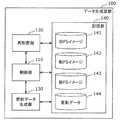
- FIG. 3 is a block diagram illustrating a configuration example of the data generation device 100 according to the present embodiment.
- the data generation device 100 includes a control unit 110, a rearrangement unit 120, an update data generation unit 130, and a storage unit 140.
- the control unit 110 may have any control function for controlling the entire data generation apparatus 100, and may be realized in any manner.
- the control unit 110 may be configured with dedicated hardware.
- the control unit 110 may be realized by executing a software program suitable for each component.
- the control unit 110 may include, for example, an arithmetic processing unit (not shown) and a storage unit (not shown) that stores a control program.
- the arithmetic processing unit include an MPU (Micro-processing Unit), a CPU (Central Processing Unit), and the like.
- Examples of the storage unit include a memory.
- the control unit 110 may be configured by a single control unit that performs centralized control, or may be configured by a plurality of control units that perform distributed control in cooperation with each other.
- the rearrangement unit 120 generates a new FS image 143. Specifically, the rearrangement unit 120 generates a new FS image 143 from the new FS image 142 and the old FS image 141.
- the new FS image 142 is an FS image of an FS image of firmware built from a new source code group (that is, firmware after update).
- the old FS image 141 is an FS image of firmware before update.
- the new FS image 143 is an FS image in which, among the files included in the new FS image 142, the files included in the old FS image 141 are arranged while suppressing changes in the file position.
- the new FS image 143 is an updated FS image in which the files included in the new FS image 142 are arranged using the position of the file in the old FS image 141.
- the firmware before the update corresponds to the first firmware
- the firmware after the update corresponds to the second firmware.
- the old FS image 141 corresponds to the first file system image
- the new FS image 143 corresponds to the second file system image.
- the rearrangement unit 120 corresponds to an arrangement unit.
- the file is arranged at the same position in the new FS image 143 as the position of the file in the old FS image 141.
- a new FS image 143 is generated.
- the rearrangement unit 120 updates the first file included in the old FS image 141 to the second file that is the second file included in the new FS image 142 and has a larger file size than the first file.
- the second file includes: (a) a third file that is part of the second file having the same file size as the first file; and (b) the part of the second file.
- the third file is divided into the remaining fourth file, and the third file is arranged in the area of the new FS image 143 corresponding to the arrangement area of the first file in the old FS image 141, and the empty area in the old FS image 141 is arranged.
- a new FS image 143 in which the fourth file is arranged in an area of the corresponding new FS image 143 may be generated.
- the rearrangement unit 120 updates the fifth file included in the old FS image 141 to the sixth file included in the new FS image 143 and having a smaller file size than the fifth file.
- the sixth file is arranged in an area of the new FS image 143 corresponding to the area where the fifth file is arranged, and the old FS image 141 is arranged in the area where the fifth file is arranged.
- an area excluding the area where the sixth file is arranged may be a free area.
- the update data generation unit 130 extracts the difference from the old FS image 141 to the new FS image 143 to generate difference data, and generates update data 144 using the difference data.
- the storage unit 140 is a component that stores various types of information.
- the storage unit 140 is, for example, an HDD (Hard Disk Drive), and may be configured from a nonvolatile memory or the like.
- the storage unit 140 may be incorporated in the data generation device 100 or may exist in a cloud server accessible by the data generation device 100.
- the storage unit 140 stores an old FS image 141, a new FS image 142, a new FS image 143, and update data 144.
- the format of the new FS image 142 is not intended to be limited to the FS image, and may be data composed of a directory group and a file group arranged under a specific directory on the mounted file system.
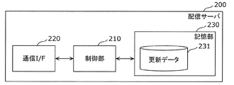
- FIG. 4 is a block diagram illustrating a configuration example of the distribution server 200 in the present embodiment.
- the distribution server 200 includes a control unit 210, a communication I / F 220, and a storage unit 230.
- the control unit 210 may have any control function for controlling the entire distribution server 200, and may be realized in any manner.
- the control unit 210 may be configured with dedicated hardware.
- the control unit 210 may be realized by executing a software program suitable for each component.
- the control unit 210 may include, for example, an arithmetic processing unit (not shown) and a storage unit (not shown) that stores a control program.
- Examples of the arithmetic processing unit include an MPU and a CPU.
- Examples of the storage unit include a memory.
- the control unit 110 may be configured by a single control unit that performs centralized control, or may be configured by a plurality of control units that perform distributed control in cooperation with each other.
- the control unit 210 distributes the update data 231 to the embedded terminal 300.
- the communication I / F 220 is a component for the distribution server 200 to communicate with the embedded terminal 300 or the like.
- the communication I / F 220 may be a communication device or a processing circuit including a communication interface.
- the communication I / F 220 communicates with the embedded terminal 300 or the like via the communication network 11 according to control by the control unit 210.
- the communication I / F 220 may be configured to send the received information to either the control unit 210 or the storage unit 230, and is configured to receive and transmit information from either the control unit 210 or the storage unit 230. Also good.
- the storage unit 230 is a component that stores various types of information.
- the storage unit 230 is, for example, an HDD, and may be configured from a nonvolatile memory or the like.
- the storage unit 230 stores update data 231.
- FIG. 5 is a block diagram illustrating a configuration example of the embedded terminal 300 according to the present embodiment.
- the embedded terminal 300 includes a control unit 310, a communication I / F 320, and a storage unit 330.
- the control unit 310 only needs to have a control function for controlling the entire embedded terminal 300, and may be realized in any manner.
- the control unit 310 may be configured with dedicated hardware.
- the control unit 310 may be realized by executing a software program suitable for each component.
- the control unit 310 may include, for example, an arithmetic processing unit (not shown) and a storage unit (not shown) that stores a control program.
- Examples of the arithmetic processing unit include an MPU and a CPU.
- Examples of the storage unit include a memory.
- the control unit 310 may be configured by a single control unit that performs centralized control, or may be configured by a plurality of control units that perform distributed control in cooperation with each other.
- the control unit 310 updates the old FS image 331 stored in the storage unit 330 using the update data 332 received from the distribution server 200.
- the communication I / F 320 is a component for the embedded terminal 300 to communicate with the distribution server 200 and the like.
- the communication I / F 320 may be a communication device or a processing circuit including a communication interface.
- the communication I / F 320 communicates with the distribution server 200 and the like via the communication network 11 under the control of the control unit 310.
- the communication I / F 320 may be configured to send the received information to either the control unit 310 or the storage unit 330, and is configured to receive and transmit information from either the control unit 310 or the storage unit 330. Also good.
- the storage unit 330 is a component that stores various types of information.
- the storage unit 330 is, for example, an HDD, and may be configured from a nonvolatile memory or the like.
- the storage unit 330 stores the old FS image 331 and the update data 332.
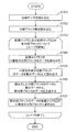
- FIG. 6 is a flowchart for explaining the operation of the data generation device 100 according to the present embodiment, more specifically, the control unit 110.
- step S401 the control unit 110 generates the new FS image 143 in which the files in the new FS image 142 are rearranged using the file size and the file arrangement in the old FS image 141 in the rearrangement unit 120. Let The generation process by the rearrangement unit 120 will be described in detail later.
- step S402 the control unit 110 causes the update data generation unit 130 to generate the update data 144 using the new FS image 143 and the old FS image 141.
- the generation process performed by the update data generation unit 130 will be described in detail later.
- FIG. 7 is a flowchart for explaining the operation of the rearrangement unit 120 in the present embodiment.
- the flowchart shown in FIG. 7 shows the process of step S401 of FIG. 6 in more detail.
- step S501 the rearrangement unit 120 copies the old FS image 141 to the new FS image 143 (FSIMG-CP).
- step S502 the relocation unit 120 mounts the new FS image 142 (FSIMG-NEW) on the directory A.
- step S503 the rearrangement unit 120 mounts the new FS image 143 (FSIMG-CP) on the directory B having the same parent directory as the directory A.
- step S504 the rearrangement unit 120 overwrites all the files of the new FS image 142 (FSIMG-NEW) while suppressing the change of the arrangement of the files in the new FS image 143 (FSIMG-CP).
- the rearrangement unit 120 overwrites all files of the new FS image 142 (FSIMG-NEW) under the directory A on the same file path under the directory B while maintaining the file attributes.
- overwriting here means updating data on the file system.
- the rearrangement unit 120 updates the data in the area currently used by the file without changing the file arrangement on the file system. Further, when the file size increases, the rearrangement unit 120 updates the data in the area currently used by the file, and arranges data that cannot be stored in the area in the free area of the file system. Further, when the file size decreases, the rearrangement unit 120 updates only the necessary data in the area currently used by the file, and records the area that is no longer needed as a free area.
- step S505 the rearrangement unit 120 converts a file that exists in the new FS image 143 (FSIMG-CP) and does not exist in the new FS image 142 (FSIMG-NEW) to the new FS image 143. Delete from (FSIMG-CP).
- step S506 the relocation unit 120 unmounts the directory A and the directory B.
- the format of the new FS image 142 is not intended to be limited to the FS image, and may be data composed of a directory group and a file group arranged under a specific directory on the mounted file system. In this case, the same effect can be obtained by omitting the mounting and unmounting procedures of the directory A.
- FIG. 8 is a flowchart for explaining the operation of the update data generation unit 130.
- the flowchart shown in FIG. 8 shows the process of step S402 of FIG. 6 in more detail.
- step S601 the update data generation unit 130 sets a division size (block size to be divided).
- the division size corresponds to a division unit.
- step S602 the update data generation unit 130 calculates the number of divided blocks for dividing the old FS image 141 and the new FS image 143 by the division size.
- the division size is a value that can divide the old FS image 141 and the new FS image 143.
- Each divided block is referred to as a divided block.
- step S603 the update data generation unit 130 repeatedly executes the processes in steps S604 to S606 below for each of the divided blocks of the old FS image 141 and the new FS image 143.
- the variable m is 1 at the first iteration, and that m increases by 1 as the number of iterations increases.
- step S604 the update data generation unit 130 reads data of the mth divided block of the old FS image 141 as old data.
- step S605 the update data generation unit 130 reads the data of the mth divided block of the new FS image 143 as new data.
- step S606 the update data generation unit 130 calculates a difference between the old data read in step S604 and the new data read in step S605, and generates a difference divided block.
- step S607 the update data generation unit 130 generates update data 144 storing each difference division block and additional information such as the division size and the number of division blocks.
- FIG. 9 is an explanatory diagram showing a configuration example of the update data 144 in the present embodiment.
- the update data is generated by the update data generation unit 130 in step S607 (FIG. 8).
- the update data 144 includes DIVSIZE, DIVNUM, OFFSET and SIZE of each of the difference division data information [0] to [NUM-1], and the difference division blocks [0] to [DIVNUM-1]. Including.
- DIVSIZE information indicating the division size of the division block is stored.
- DIVNUM stores information indicating the number of divided blocks.
- Each OFFSET of the difference division data information [0] to [NUM-1] stores information (offset) indicating the head address of each difference division block.
- each SIZE stores information including the size of each difference division block.
- the difference division blocks [0] to [DIVNUM-1] store the data of each difference division block.
- the storage unit 330 of the built-in terminal 300 holds the old FS image 331.
- the control unit 310 of the embedded terminal 300 updates the firmware from the old FS image 331 and the update data 332.
- FIG. 10 is a flowchart showing an operation example of the embedded terminal 300.
- an area where the old FS image 331 is written in the storage unit 330 is defined as a recording area E1 (not shown).
- an area in which a new FS image generated from the old FS image 331 and the update data 332 is written is a recording area E2 (not shown).
- step S701 the control unit 310 of the embedded terminal 300 reads the division size from the update data 332 while the old firmware (the program in the old FS image 331) written in the recording area E1 is activated.
- step S ⁇ b> 702 the control unit 310 reads the number of divided blocks from the update data 332.
- step S703 the control unit 310 repeatedly executes the following processes in steps S704 to S707 for each divided block size for the recording area E1 and the recording area E2 by the number of divided blocks. Assume that the variable m is 1 at the first iteration, and that m increases by 1 as the number of iterations increases.
- step S704 the control unit 310 reads the data of the mth divided block in the recording area E1 as old data.
- step S705 the control unit 310 reads the data of the mth difference division block from the update data 332 as difference data.
- step S706 the control unit 310 generates new divided block data from the old data and the difference data.
- step S707 the control unit 310 writes the data of the new divided block in the mth divided block of the recording area E2.
- control unit 310 is activated using the new firmware stored in the recording area E2 instead of the old firmware on the recording area E1.
- FIG. 11 is an explanatory diagram showing an operation example of the rearrangement unit 120 in the present embodiment.
- FIG. 11 shows an old FS image 800 and a new FS image 810.
- the file system size of the old FS image 800 and the new FS image 810 is 8 Mbytes.
- management information 801 (1 MByte)
- files A, B, C, D and E each 1 MByte
- free capacity (2 MByte) are arranged in this order from the top of the file system.
- all the empty areas are initialized to 0, for example.
- management information 811 (1 MByte), file A (1 MByte), file B1 (2 MByte), files C, D and E (each 1 MByte), and free space (1 MByte) are included from the top of the file system. Are arranged in this order.
- the difference from the old FS image 800 to the new FS image 810 is that the file B whose file size is 1 MByte is updated to the file B1 whose file size is 2 MByte.
- the file B corresponds to the first file
- the file B1 corresponds to the second file.
- the file B is arranged in the area of addresses 0x00200000 to 0x002FFFFF, and the files C, D, and E are arranged in order in the area after the address 0x00300000 without gaps.
- the file B1 is arranged in the area of addresses 0x00200000 to 0x003FFFFF, and the files C, D, and E are arranged in order in the area after the address 0x00400000 without gaps.
- the rearrangement unit 120 copies the old FS image 800 to an area on the storage unit 140 (step S501).
- the area where the old FS image 800 has been copied is an area that will be treated as the new FS image 820 later.
- the relocation unit 120 mounts the new FS image 810 at / mnt / a so that the file in the file system of the new FS image 810 can be accessed.
- / Mnt / a corresponds to the directory A (step S502).
- the relocation unit 120 mounts the area where the old FS image 800 is copied to / mnt / b so that the files in the file system included in the area can be accessed.
- / Mnt / b corresponds to the directory B (step S503).
- the rearrangement unit 120 overwrites all files under / mnt / a while maintaining the file attributes in the same file path at / mnt / b. That is, the rearrangement unit 120 generates the new FS image 820 by rearranging the new FS image 810 while suppressing the change of the file arrangement from the old FS image 800.
- the relocation unit 120 includes a file B11 that is a part of a size that can store the file B1 included in the new FS image 820 in the area where the file B is arranged in the old FS image 800, and The remaining file B12 is divided.
- the rearrangement unit 120 arranges the file B11 in an area in the new FS image 820 having the same address as the area in which the file B is arranged in the old FS image 800. Further, the rearrangement unit 120 arranges the file B12 in an empty area in the old FS image 800 (step S504).
- the file B11 corresponds to the third file
- the file B12 corresponds to the fourth file.
- the relocation unit 120 updates the management information 801 to the management information 821. This is because the new FS image 820 changes the arrangement and size of files in the file system compared to the old FS image 800.
- the rearrangement unit 120 unmounts / mnt / a and / mnt / b (step S506).
- FIG. 12 is an explanatory diagram showing an operation example of the update data generation unit 130 in the present embodiment.
- FIG. 12 shows an old FS image 800, a new FS image 820, comparison data 830, and update data 840.
- the update data generation unit 130 generates difference data from the old FS image 800 and the new FS image 820.
- the difference data is extracted using, for example, the BSDIFF algorithm disclosed in Non-Patent Document 1.
- the division size is 1 MByte and the number of division blocks is 8.
- the update data generation unit 130 divides the old FS image 800 and the new FS image 820 for each division size from the top, and extracts the difference between the blocks arranged at the same position in each FS image, so that the comparison block 831 to 838 (that is, comparison data 830) are generated.
- the update data generation unit 130 uses the comparison blocks 831 to 838 to generate update data 840 including the difference division blocks 841 to 848.
- the update data generation unit 130 determines that there is no difference between the comparison blocks 832, 834, 835, 836, and 838 because the data is the same in the old FS image 800 and the new FS image 820. Generate relatively small sized difference partition blocks 842, 844, 845, 846 and 848 which mean. On the other hand, since there is a difference in data between the old FS image 800 and the new FS image 820 with respect to the comparison blocks 831, 833, and 837, the update data generation unit 130 includes difference division blocks 841, 843, and 847 that indicate the differences. Is generated.
- the significance of the data generation apparatus 100 of the present embodiment will be described by comparing the comparison block generated by the update data generation unit 130 in the present embodiment with the comparison block generated by the related technique (FIG. 1).
- the old FS image and the new FS image are substantially the same as shown in FIGS.
- comparison blocks 41, 43, 44, 45, 46, and 47 including the differences.
- comparison blocks generated by the update data generation unit 130 according to the present embodiment there are three comparison blocks 831, 833, and 837 that include a difference. In this way, comparison blocks including differences are reduced, and the amount of update data is suppressed.
- the data generation apparatus according to the present embodiment can suppress the file size of the firmware update data.
- FIG. 13 is an explanatory diagram showing an operation example of the embedded terminal 300 in the present embodiment.
- the update data 840 is update data 332 received by the embedded terminal 300 from the distribution server 200 and stored in the storage unit 330.
- the old FS image 850 is the old FS image 331.
- the control unit 310 of the embedded terminal 300 generates new divided block data for each block from the old FS image 850 and the update data 840 stored in the storage unit 330 and writes them as a new FS image 860.
- the management information 851 included in the old FS image 850 is rewritten to the management information 861 included in the new FS image 860.
- the control unit 310 generates a new FS image from the old FS image 850.
- FIG. 14 is an explanatory diagram illustrating another operation example of the rearrangement unit 120 according to the present embodiment.
- FIG. 14 shows an old FS image 900 and a new FS image 910.
- the file system size of the old FS image 900 and the new FS image 910 is 8 MByte.
- management information 901 (1 MByte), files A, B, C, D and E (each 1 MByte), and free capacity (2 MByte) are arranged in this order from the top of the file system.
- all the empty areas are initialized to 0, for example.
- management information 911 (1 MByte), file A (1 MByte), file B3 (0.5 MByte), files C, D and E (each 1 MByte), and free space (2 from the top of the file system) .5 MByte) are arranged in this order.
- the difference from the old FS image 900 to the new FS image 910 is that the file B whose file size is 1 MByte is updated to the file B3 whose file size is 0.5 MByte.
- the file B is arranged in the area of addresses 0x00200000 to 0x002FFFFF, and the files C, D, and E are arranged in order in the area after the address 0x00300000 without gaps.
- the file B3 is arranged in the area of addresses 0x00200000 to 0x0027FFFF, and the files C, D, and E are arranged in order in the area after the address 0x00280000 without gaps.
- the rearrangement unit 120 performs the same operation as that described in the first operation example. Here, the description will focus on data generated during operation.
- the rearrangement unit 120 rearranges the new FS image 910 while suppressing the file layout change from the old FS image 900 with respect to the new FS image 920 obtained by copying the old FS image 900.
- the rearrangement unit 120 stores the file B3 in a part of the area where the file B is arranged in the old FS image 900 (address 0x00200000 to 0x0027FFFF), and the rest (address 0x00280000 to 0x002FFFFF) Free space.
- the rearrangement unit 120 updates the management information 901 to the management information 921. This is because the new FS image 920 has a changed file arrangement and size in the file system compared to the old FS image 900.
- the file B corresponds to the fifth file
- the file B3 corresponds to the sixth file.
- FIG. 15 is an explanatory diagram illustrating another operation example of the update data generation unit 130 in the present embodiment.
- the update data generation unit 130 performs the same operation as that described in the first operation example. Here, the description will focus on data generated during operation.
- the update data generation unit 130 divides the old FS image 900 and the new FS image 920 from the top for each division size, and extracts the difference between the blocks arranged at the same position, thereby comparing blocks 931 to 938 ( That is, comparison data 930) is generated.
- the update data generation unit 130 generates update data 940 including the difference division blocks 941 to 948 using the comparison blocks 931 to 938.
- the update data generation unit 130 has no difference between the comparison blocks 932, 934, 935, 936, 937, and 938 because the data is the same between the old FS image 900 and the new FS image 920. This means that comparatively small size difference division blocks 942, 944, 945, 946, 947 and 948 are generated.
- the difference data exists between the old FS image 900 and the new FS image 920, so the update data generation unit 130 generates difference division blocks 941 and 943 indicating the difference.
- the significance of the data generation apparatus 100 of this embodiment will be described by comparing the comparison block generated by the update data generation unit 130 in this embodiment with the comparison block generated by the related technology.
- FIG. 16 is an explanatory diagram showing another example of the operation of the embedded terminal 300 in the present embodiment.
- the update data 940 is update data 332 received by the embedded terminal 300 from the distribution server 200 and stored in the storage unit 330.
- the old FS image 950 is the old FS image 331.
- the control unit 310 of the embedded terminal 300 generates new divided block data for each block from the old FS image 950 and the update data 940 stored in the storage unit 330, and writes the new divided block data as the new FS image 960.
- the management information 951 included in the old FS image 950 is rewritten to the management information 961 included in the new FS image 960.
- the control unit 310 generates a new FS image from the old FS image 950.
- the data generation device uses the file position in the first file system image of the first firmware that is the firmware before the update, and uses the second firmware that is the firmware after the update.
- An update unit that generates a second file system image in which files included in the file are generated, and an update data generator that generates update data using a difference from the first file system image to the second file system image generated by the placement unit A part.
- the data generation device since the data generation device uses the position of the file in the first file system image when generating the second file system image, the data amount of the update data generated by the update data generation unit using the difference Can be suppressed. Therefore, the data generation device can suppress the file size of the firmware update data. This has an advantage that, for example, when firmware update is required after product shipment, the amount of communication when firmware update data is distributed by communication or the like can be suppressed.
- the arrangement unit is configured so that the position of the file in the first file system image A second file system image in which files are arranged at positions may be generated.
- the data generation device maintains the file included in both the first firmware and the second firmware without changing the position in the file system image.
- the update data generation unit does not calculate the difference for the file.
- the data generation device can suppress the data amount of the update data.
- the placement unit determines that the second file is (a)
- the first file system is divided into a third file that is a part of the second file having the same file size as the first file, and a fourth file that is a remaining part of the second file excluding a part of the second file.
- the third file is placed in the area of the second file system image corresponding to the placement area of the first file in the image
- the fourth file is placed in the area of the second file system image corresponding to the empty area in the first file system image.
- the second file system image may be generated.
- the update data generation unit does not calculate the difference for the other files.
- the data generation device can suppress the data amount of the update data.
- the arranging unit may change the fifth file in the first file system image.
- the sixth file is arranged in the area in the second file system image corresponding to the area where the file is arranged, and the area in the second file system image corresponding to the area in which the fifth file is arranged in the first file system image.
- the area excluding the area where the sixth file is arranged may be a free area.
- the update data generation unit does not calculate the difference for the other files.
- the data generation device can suppress the data amount of the update data.
- the embedded terminal according to the present embodiment is an embedded terminal that operates with updatable firmware, and stores a first firmware that is firmware before update, and (a) first Update data generated using difference data indicating a difference from the first file system image of one firmware to the second file system image is acquired and stored in the storage unit, and (b) the storage unit stores the update data.
- a control unit that updates the firmware using the first firmware and the update data, and the second file system image is firmware that has been updated by using arrangement information indicating the arrangement of files in the first file system image. It is a file system image in which files included in the second firmware are arranged.
- the embedded terminal can update the firmware using the update data generated so that the data generation device suppresses the data amount of the update data.
- the firmware update system includes the above-described data generation device, an embedded terminal that acquires update data generated by the data generation device, and updates the firmware using the acquired update data, and data generation Update data generated by the apparatus, and a distribution server that distributes the stored update data to the embedded terminal.
- the embedded terminal stores the first firmware that is the firmware before the update. And (a) from the first file system image of the first firmware, update data generated using difference data indicating the difference to the second file system image is acquired and stored in the storage unit ( b) a first firmware stored in the storage unit and a control unit for updating the firmware using the update data; System image, using the location of the file in the first file system image is a file system image of arranging the files contained in the second firmware is firmware after the update.
- the storage unit of the embedded terminal stores the first version firmware as the first firmware
- the update data generation unit stores the firmware files for each of the plurality of versions.
- the distribution server uses the system image as the first file system image and using the second version firmware file system image different from the first version as the second file system image, multiple update data are generated, and the distribution server generates the update data The update data generated by the first version firmware and the second version firmware among the plurality of update data held by the To deliver.
- the data generation method according to the present embodiment is included in the second firmware that is the firmware after the update, using the file position in the first file system image of the first firmware that is the firmware before the update.
- the file system sizes of the old FS image and the new FS image are the same size, and the division size is a size that can be divided by the old FS image and the new FS image, but is not limited to this.
- the distribution server may acquire the firmware version of the embedded terminal and distribute update data for appropriate version upgrade.
- the distribution server distributes multiple update data for several generations when the firmware version of the acquired embedded device and the latest released version are different by several generations.
- update data for upgrading at a time may be distributed.
- the distribution server may cause the update data generation device to generate update data for version upgrade at the time of distribution, or cause the update data generation device to generate update data when the version is shifted several generations in advance, You may manage it.
- the storage unit of the embedded terminal stores the first version firmware as the first firmware
- the update data generation unit uses the file system image of each of the multiple versions as the first file system image.
- the second version firmware file system image different from the first version is used as the second file system image to generate a plurality of update data
- the distribution server holds the plurality of update data generated by the update data generation unit
- the update data generated by using the first version firmware and the second version firmware among the plurality of update data held may be distributed to the embedded terminal.
- This disclosure is applicable to devices that generate data for updating firmware.
- the present disclosure can be applied to a firmware update data generation device mounted on an in-vehicle display audio, a digital television, a hard disk recorder, a smartphone, or the like.
Landscapes
- Engineering & Computer Science (AREA)
- Theoretical Computer Science (AREA)
- Quality & Reliability (AREA)
- Physics & Mathematics (AREA)
- General Engineering & Computer Science (AREA)
- General Physics & Mathematics (AREA)
- Stored Programmes (AREA)
- Information Retrieval, Db Structures And Fs Structures Therefor (AREA)
Abstract
L'invention concerne un appareil de génération de données (100) comportant: une unité de réagencement (120) qui génère une seconde image de système de fichier dans laquelle un fichier inclus dans un second micrologiciel, qui est un micrologiciel après la mise à jour, est agencé en utilisant la position d'un fichier dans une première image de système de fichier d'un premier micrologiciel, qui est un micrologiciel avant la mise à jour; et une unité de génération de données de mise à jour (130) qui génère des données de mise à jour en utilisant une différence entre la première image de système de fichier et la seconde image de système de fichier générée par l'unité de réagencement (120).
Applications Claiming Priority (2)
| Application Number | Priority Date | Filing Date | Title |
|---|---|---|---|
| JP2016-050337 | 2016-03-15 | ||
| JP2016050337 | 2016-03-15 |
Publications (1)
| Publication Number | Publication Date |
|---|---|
| WO2017158663A1 true WO2017158663A1 (fr) | 2017-09-21 |
Family
ID=59850707
Family Applications (1)
| Application Number | Title | Priority Date | Filing Date |
|---|---|---|---|
| PCT/JP2016/004682 WO2017158663A1 (fr) | 2016-03-15 | 2016-10-25 | Appareil de génération de données, terminal incorporé, système de mise à jour de micrologiciel et procédé de génération de données |
Country Status (1)
| Country | Link |
|---|---|
| WO (1) | WO2017158663A1 (fr) |
Cited By (1)
| Publication number | Priority date | Publication date | Assignee | Title |
|---|---|---|---|---|
| CN110390064A (zh) * | 2019-07-25 | 2019-10-29 | 深圳市腾讯计算机系统有限公司 | 文件更新方法、装置和系统,存储介质及电子装置 |
Citations (2)
| Publication number | Priority date | Publication date | Assignee | Title |
|---|---|---|---|---|
| JP2007524171A (ja) * | 2004-02-27 | 2007-08-23 | テレフオンアクチーボラゲット エル エム エリクソン(パブル) | フラッシュメモリのプログラミング |
| US20090113386A1 (en) * | 2005-08-18 | 2009-04-30 | Johan Eker | Object code generation for increased delta performance |
-
2016
- 2016-10-25 WO PCT/JP2016/004682 patent/WO2017158663A1/fr active Application Filing
Patent Citations (2)
| Publication number | Priority date | Publication date | Assignee | Title |
|---|---|---|---|---|
| JP2007524171A (ja) * | 2004-02-27 | 2007-08-23 | テレフオンアクチーボラゲット エル エム エリクソン(パブル) | フラッシュメモリのプログラミング |
| US20090113386A1 (en) * | 2005-08-18 | 2009-04-30 | Johan Eker | Object code generation for increased delta performance |
Cited By (1)
| Publication number | Priority date | Publication date | Assignee | Title |
|---|---|---|---|---|
| CN110390064A (zh) * | 2019-07-25 | 2019-10-29 | 深圳市腾讯计算机系统有限公司 | 文件更新方法、装置和系统,存储介质及电子装置 |
Similar Documents
| Publication | Publication Date | Title |
|---|---|---|
| US10055216B2 (en) | Minimizing image copying during partition updates | |
| AU2014218837B2 (en) | Deduplication storage system with efficient reference updating and space reclamation | |
| US8682874B2 (en) | Information processing system | |
| US9250946B2 (en) | Efficient provisioning of cloned virtual machine images using deduplication metadata | |
| US20170277556A1 (en) | Distribution system, computer, and arrangement method for virtual machine | |
| US9031906B2 (en) | Method of managing data in asymmetric cluster file system | |
| US10162527B2 (en) | Scalable and efficient access to and management of data and resources in a tiered data storage system | |
| JP5886447B2 (ja) | ロケーション非依存のファイル | |
| CN104580439B (zh) | 一种云存储系统中使数据均匀分布的方法 | |
| US9900386B2 (en) | Provisioning data to distributed computing systems | |
| US10169345B2 (en) | Moving data from linear tape file system storage to cloud storage | |
| US20150373102A1 (en) | Deployment of virtual machine disks from a shared network file system | |
| JP4755244B2 (ja) | 情報生成方法、情報生成プログラム及び情報生成装置 | |
| EP2669806B1 (fr) | Système de mémorisation | |
| US10346256B1 (en) | Client side cache for deduplication backup systems | |
| US8332844B1 (en) | Root image caching and indexing for block-level distributed application management | |
| US11176089B2 (en) | Systems and methods for implementing dynamic file systems | |
| WO2017158663A1 (fr) | Appareil de génération de données, terminal incorporé, système de mise à jour de micrologiciel et procédé de génération de données | |
| US20080228808A1 (en) | System for deploying data from deployment-source device to deployment-destination device | |
| JP2006079463A (ja) | 時系列データ記録用バッファ管理方法、装置、システムおよびプログラム | |
| US20190065067A1 (en) | Backup files to a disk image | |
| US20180322187A1 (en) | Dynamic alternate keys for use in file systems utilizing a keyed index | |
| WO2019055195A1 (fr) | Approvisionnement efficace de machines virtuelles à un équipement informatique de point d'extrémité | |
| US11640339B2 (en) | Creating a backup data set | |
| CN106033454B (zh) | 虚拟文件系统的格式化方法、处理方法和装置 |
Legal Events
| Date | Code | Title | Description |
|---|---|---|---|
| NENP | Non-entry into the national phase |
Ref country code: DE |
|
| 121 | Ep: the epo has been informed by wipo that ep was designated in this application |
Ref document number: 16894287 Country of ref document: EP Kind code of ref document: A1 |
|
| 122 | Ep: pct application non-entry in european phase |
Ref document number: 16894287 Country of ref document: EP Kind code of ref document: A1 |
|
| NENP | Non-entry into the national phase |
Ref country code: JP |