WO2017155338A1 - Anti-reflective film - Google Patents
Anti-reflective film Download PDFInfo
- Publication number
- WO2017155338A1 WO2017155338A1 PCT/KR2017/002583 KR2017002583W WO2017155338A1 WO 2017155338 A1 WO2017155338 A1 WO 2017155338A1 KR 2017002583 W KR2017002583 W KR 2017002583W WO 2017155338 A1 WO2017155338 A1 WO 2017155338A1
- Authority
- WO
- WIPO (PCT)
- Prior art keywords
- layer
- low refractive
- inorganic nanoparticles
- refractive index
- scattering
- Prior art date
Links
- 230000003667 anti-reflective effect Effects 0.000 title claims abstract description 13
- 239000013598 vector Substances 0.000 claims abstract description 54
- 239000010410 layer Substances 0.000 claims description 207
- 239000002105 nanoparticle Substances 0.000 claims description 149
- 239000007787 solid Substances 0.000 claims description 89
- 150000001875 compounds Chemical class 0.000 claims description 82
- 239000011247 coating layer Substances 0.000 claims description 61
- 125000000524 functional group Chemical group 0.000 claims description 34
- NIXOWILDQLNWCW-UHFFFAOYSA-M acrylate group Chemical group C(C=C)(=O)[O-] NIXOWILDQLNWCW-UHFFFAOYSA-M 0.000 claims description 32
- 239000011347 resin Substances 0.000 claims description 31
- 229920005989 resin Polymers 0.000 claims description 31
- 239000002245 particle Substances 0.000 claims description 24
- 238000000576 coating method Methods 0.000 claims description 22
- 239000011230 binding agent Substances 0.000 claims description 21
- 239000011248 coating agent Substances 0.000 claims description 19
- 229920001577 copolymer Polymers 0.000 claims description 17
- 239000010419 fine particle Substances 0.000 claims description 14
- 125000000391 vinyl group Chemical group [H]C([*])=C([H])[H] 0.000 claims description 9
- 239000010954 inorganic particle Substances 0.000 claims description 8
- 230000001678 irradiating effect Effects 0.000 claims description 8
- 125000003396 thiol group Chemical group [H]S* 0.000 claims description 5
- 238000004132 cross linking Methods 0.000 claims description 4
- 125000003700 epoxy group Chemical group 0.000 claims 1
- 230000005855 radiation Effects 0.000 abstract 1
- 239000008199 coating composition Substances 0.000 description 40
- 229910052731 fluorine Inorganic materials 0.000 description 35
- 239000011737 fluorine Substances 0.000 description 35
- YCKRFDGAMUMZLT-UHFFFAOYSA-N Fluorine atom Chemical compound [F] YCKRFDGAMUMZLT-UHFFFAOYSA-N 0.000 description 33
- -1 acryl Chemical group 0.000 description 25
- 230000003373 anti-fouling effect Effects 0.000 description 22
- VYPSYNLAJGMNEJ-UHFFFAOYSA-N Silicium dioxide Chemical compound O=[Si]=O VYPSYNLAJGMNEJ-UHFFFAOYSA-N 0.000 description 21
- 230000000052 comparative effect Effects 0.000 description 18
- 238000000034 method Methods 0.000 description 16
- IJGRMHOSHXDMSA-UHFFFAOYSA-N Atomic nitrogen Chemical compound N#N IJGRMHOSHXDMSA-UHFFFAOYSA-N 0.000 description 14
- 238000001035 drying Methods 0.000 description 14
- 238000004519 manufacturing process Methods 0.000 description 13
- 239000000178 monomer Substances 0.000 description 12
- 239000003960 organic solvent Substances 0.000 description 12
- 229920000642 polymer Polymers 0.000 description 12
- 238000002360 preparation method Methods 0.000 description 12
- 238000005259 measurement Methods 0.000 description 11
- 229910052751 metal Inorganic materials 0.000 description 9
- 239000002184 metal Substances 0.000 description 9
- 239000011342 resin composition Substances 0.000 description 9
- 239000000377 silicon dioxide Substances 0.000 description 9
- 239000003999 initiator Substances 0.000 description 8
- 238000002834 transmittance Methods 0.000 description 8
- KFZMGEQAYNKOFK-UHFFFAOYSA-N Isopropanol Chemical compound CC(C)O KFZMGEQAYNKOFK-UHFFFAOYSA-N 0.000 description 7
- XUIMIQQOPSSXEZ-UHFFFAOYSA-N Silicon Chemical group [Si] XUIMIQQOPSSXEZ-UHFFFAOYSA-N 0.000 description 7
- 229910052757 nitrogen Inorganic materials 0.000 description 7
- 238000000016 photochemical curing Methods 0.000 description 7
- 239000010703 silicon Substances 0.000 description 7
- 229910052710 silicon Inorganic materials 0.000 description 7
- 239000000758 substrate Substances 0.000 description 7
- ZWEHNKRNPOVVGH-UHFFFAOYSA-N 2-Butanone Chemical compound CCC(C)=O ZWEHNKRNPOVVGH-UHFFFAOYSA-N 0.000 description 6
- XEKOWRVHYACXOJ-UHFFFAOYSA-N Ethyl acetate Chemical compound CCOC(C)=O XEKOWRVHYACXOJ-UHFFFAOYSA-N 0.000 description 6
- OKKJLVBELUTLKV-UHFFFAOYSA-N Methanol Chemical compound OC OKKJLVBELUTLKV-UHFFFAOYSA-N 0.000 description 6
- NTIZESTWPVYFNL-UHFFFAOYSA-N Methyl isobutyl ketone Chemical compound CC(C)CC(C)=O NTIZESTWPVYFNL-UHFFFAOYSA-N 0.000 description 6
- PPBRXRYQALVLMV-UHFFFAOYSA-N Styrene Chemical compound C=CC1=CC=CC=C1 PPBRXRYQALVLMV-UHFFFAOYSA-N 0.000 description 6
- XLOMVQKBTHCTTD-UHFFFAOYSA-N Zinc monoxide Chemical compound [Zn]=O XLOMVQKBTHCTTD-UHFFFAOYSA-N 0.000 description 6
- HVVWZTWDBSEWIH-UHFFFAOYSA-N [2-(hydroxymethyl)-3-prop-2-enoyloxy-2-(prop-2-enoyloxymethyl)propyl] prop-2-enoate Chemical compound C=CC(=O)OCC(CO)(COC(=O)C=C)COC(=O)C=C HVVWZTWDBSEWIH-UHFFFAOYSA-N 0.000 description 6
- 238000000572 ellipsometry Methods 0.000 description 6
- 239000000203 mixture Chemical group 0.000 description 6
- 230000010287 polarization Effects 0.000 description 6
- 238000006243 chemical reaction Methods 0.000 description 5
- 239000000463 material Substances 0.000 description 5
- 238000006116 polymerization reaction Methods 0.000 description 5
- 239000000126 substance Substances 0.000 description 5
- WYURNTSHIVDZCO-UHFFFAOYSA-N Tetrahydrofuran Chemical compound C1CCOC1 WYURNTSHIVDZCO-UHFFFAOYSA-N 0.000 description 4
- 150000004703 alkoxides Chemical class 0.000 description 4
- PNEYBMLMFCGWSK-UHFFFAOYSA-N aluminium oxide Inorganic materials [O-2].[O-2].[O-2].[Al+3].[Al+3] PNEYBMLMFCGWSK-UHFFFAOYSA-N 0.000 description 4
- 239000002216 antistatic agent Substances 0.000 description 4
- 230000005540 biological transmission Effects 0.000 description 4
- 239000003795 chemical substances by application Substances 0.000 description 4
- 238000001723 curing Methods 0.000 description 4
- SWXVUIWOUIDPGS-UHFFFAOYSA-N diacetone alcohol Chemical compound CC(=O)CC(C)(C)O SWXVUIWOUIDPGS-UHFFFAOYSA-N 0.000 description 4
- 125000005442 diisocyanate group Chemical group 0.000 description 4
- 150000002576 ketones Chemical class 0.000 description 4
- 230000000704 physical effect Effects 0.000 description 4
- 238000010926 purge Methods 0.000 description 4
- XLYOFNOQVPJJNP-UHFFFAOYSA-N water Substances O XLYOFNOQVPJJNP-UHFFFAOYSA-N 0.000 description 4
- PCKZAVNWRLEHIP-UHFFFAOYSA-N 2-hydroxy-1-[4-[[4-(2-hydroxy-2-methylpropanoyl)phenyl]methyl]phenyl]-2-methylpropan-1-one Chemical compound C1=CC(C(=O)C(C)(O)C)=CC=C1CC1=CC=C(C(=O)C(C)(C)O)C=C1 PCKZAVNWRLEHIP-UHFFFAOYSA-N 0.000 description 3
- LFQSCWFLJHTTHZ-UHFFFAOYSA-N Ethanol Chemical compound CCO LFQSCWFLJHTTHZ-UHFFFAOYSA-N 0.000 description 3
- LYCAIKOWRPUZTN-UHFFFAOYSA-N Ethylene glycol Chemical compound OCCO LYCAIKOWRPUZTN-UHFFFAOYSA-N 0.000 description 3
- PEDCQBHIVMGVHV-UHFFFAOYSA-N Glycerine Chemical compound OCC(O)CO PEDCQBHIVMGVHV-UHFFFAOYSA-N 0.000 description 3
- UIHCLUNTQKBZGK-UHFFFAOYSA-N Methyl isobutyl ketone Natural products CCC(C)C(C)=O UIHCLUNTQKBZGK-UHFFFAOYSA-N 0.000 description 3
- ZMXDDKWLCZADIW-UHFFFAOYSA-N N,N-Dimethylformamide Chemical compound CN(C)C=O ZMXDDKWLCZADIW-UHFFFAOYSA-N 0.000 description 3
- YXFVVABEGXRONW-UHFFFAOYSA-N Toluene Chemical compound CC1=CC=CC=C1 YXFVVABEGXRONW-UHFFFAOYSA-N 0.000 description 3
- 150000001298 alcohols Chemical class 0.000 description 3
- 239000003054 catalyst Substances 0.000 description 3
- 239000002612 dispersion medium Substances 0.000 description 3
- 150000002118 epoxides Chemical group 0.000 description 3
- 150000002170 ethers Chemical class 0.000 description 3
- 125000004435 hydrogen atom Chemical group [H]* 0.000 description 3
- 230000003287 optical effect Effects 0.000 description 3
- 238000005191 phase separation Methods 0.000 description 3
- 239000002952 polymeric resin Substances 0.000 description 3
- 230000008569 process Effects 0.000 description 3
- 229910000077 silane Inorganic materials 0.000 description 3
- 150000003377 silicon compounds Chemical class 0.000 description 3
- 239000002904 solvent Substances 0.000 description 3
- 229920003002 synthetic resin Polymers 0.000 description 3
- XOLBLPGZBRYERU-UHFFFAOYSA-N tin dioxide Chemical compound O=[Sn]=O XOLBLPGZBRYERU-UHFFFAOYSA-N 0.000 description 3
- 229910001887 tin oxide Inorganic materials 0.000 description 3
- 239000008096 xylene Substances 0.000 description 3
- 239000011787 zinc oxide Substances 0.000 description 3
- MYRTYDVEIRVNKP-UHFFFAOYSA-N 1,2-Divinylbenzene Chemical compound C=CC1=CC=CC=C1C=C MYRTYDVEIRVNKP-UHFFFAOYSA-N 0.000 description 2
- TXBCBTDQIULDIA-UHFFFAOYSA-N 2-[[3-hydroxy-2,2-bis(hydroxymethyl)propoxy]methyl]-2-(hydroxymethyl)propane-1,3-diol Chemical compound OCC(CO)(CO)COCC(CO)(CO)CO TXBCBTDQIULDIA-UHFFFAOYSA-N 0.000 description 2
- XLLIQLLCWZCATF-UHFFFAOYSA-N 2-methoxyethyl acetate Chemical compound COCCOC(C)=O XLLIQLLCWZCATF-UHFFFAOYSA-N 0.000 description 2
- KUDUQBURMYMBIJ-UHFFFAOYSA-N 2-prop-2-enoyloxyethyl prop-2-enoate Chemical compound C=CC(=O)OCCOC(=O)C=C KUDUQBURMYMBIJ-UHFFFAOYSA-N 0.000 description 2
- YEJRWHAVMIAJKC-UHFFFAOYSA-N 4-Butyrolactone Chemical compound O=C1CCCO1 YEJRWHAVMIAJKC-UHFFFAOYSA-N 0.000 description 2
- SOGAXMICEFXMKE-UHFFFAOYSA-N Butylmethacrylate Chemical compound CCCCOC(=O)C(C)=C SOGAXMICEFXMKE-UHFFFAOYSA-N 0.000 description 2
- 229920002284 Cellulose triacetate Polymers 0.000 description 2
- LRHPLDYGYMQRHN-UHFFFAOYSA-N N-Butanol Chemical compound CCCCO LRHPLDYGYMQRHN-UHFFFAOYSA-N 0.000 description 2
- NBIIXXVUZAFLBC-UHFFFAOYSA-N Phosphoric acid Chemical compound OP(O)(O)=O NBIIXXVUZAFLBC-UHFFFAOYSA-N 0.000 description 2
- 239000002202 Polyethylene glycol Substances 0.000 description 2
- 239000004721 Polyphenylene oxide Substances 0.000 description 2
- ATUOYWHBWRKTHZ-UHFFFAOYSA-N Propane Chemical compound CCC ATUOYWHBWRKTHZ-UHFFFAOYSA-N 0.000 description 2
- DKGAVHZHDRPRBM-UHFFFAOYSA-N Tert-Butanol Chemical compound CC(C)(C)O DKGAVHZHDRPRBM-UHFFFAOYSA-N 0.000 description 2
- GWEVSGVZZGPLCZ-UHFFFAOYSA-N Titan oxide Chemical compound O=[Ti]=O GWEVSGVZZGPLCZ-UHFFFAOYSA-N 0.000 description 2
- ZJCCRDAZUWHFQH-UHFFFAOYSA-N Trimethylolpropane Chemical compound CCC(CO)(CO)CO ZJCCRDAZUWHFQH-UHFFFAOYSA-N 0.000 description 2
- DAKWPKUUDNSNPN-UHFFFAOYSA-N Trimethylolpropane triacrylate Chemical compound C=CC(=O)OCC(CC)(COC(=O)C=C)COC(=O)C=C DAKWPKUUDNSNPN-UHFFFAOYSA-N 0.000 description 2
- NNLVGZFZQQXQNW-ADJNRHBOSA-N [(2r,3r,4s,5r,6s)-4,5-diacetyloxy-3-[(2s,3r,4s,5r,6r)-3,4,5-triacetyloxy-6-(acetyloxymethyl)oxan-2-yl]oxy-6-[(2r,3r,4s,5r,6s)-4,5,6-triacetyloxy-2-(acetyloxymethyl)oxan-3-yl]oxyoxan-2-yl]methyl acetate Chemical compound O([C@@H]1O[C@@H]([C@H]([C@H](OC(C)=O)[C@H]1OC(C)=O)O[C@H]1[C@@H]([C@@H](OC(C)=O)[C@H](OC(C)=O)[C@@H](COC(C)=O)O1)OC(C)=O)COC(=O)C)[C@@H]1[C@@H](COC(C)=O)O[C@@H](OC(C)=O)[C@H](OC(C)=O)[C@H]1OC(C)=O NNLVGZFZQQXQNW-ADJNRHBOSA-N 0.000 description 2
- 150000001242 acetic acid derivatives Chemical class 0.000 description 2
- YRKCREAYFQTBPV-UHFFFAOYSA-N acetylacetone Chemical compound CC(=O)CC(C)=O YRKCREAYFQTBPV-UHFFFAOYSA-N 0.000 description 2
- 125000001931 aliphatic group Chemical group 0.000 description 2
- 238000007611 bar coating method Methods 0.000 description 2
- 230000008859 change Effects 0.000 description 2
- 229920001940 conductive polymer Polymers 0.000 description 2
- 230000007547 defect Effects 0.000 description 2
- 238000007607 die coating method Methods 0.000 description 2
- 238000007865 diluting Methods 0.000 description 2
- 238000009826 distribution Methods 0.000 description 2
- 230000000694 effects Effects 0.000 description 2
- 150000002148 esters Chemical class 0.000 description 2
- 238000002474 experimental method Methods 0.000 description 2
- 125000001153 fluoro group Chemical group F* 0.000 description 2
- 238000007756 gravure coating Methods 0.000 description 2
- 239000001257 hydrogen Substances 0.000 description 2
- 229910052739 hydrogen Inorganic materials 0.000 description 2
- 229910003437 indium oxide Inorganic materials 0.000 description 2
- PJXISJQVUVHSOJ-UHFFFAOYSA-N indium(iii) oxide Chemical compound [O-2].[O-2].[O-2].[In+3].[In+3] PJXISJQVUVHSOJ-UHFFFAOYSA-N 0.000 description 2
- 239000004615 ingredient Substances 0.000 description 2
- JMMWKPVZQRWMSS-UHFFFAOYSA-N isopropyl acetate Chemical compound CC(C)OC(C)=O JMMWKPVZQRWMSS-UHFFFAOYSA-N 0.000 description 2
- 229910044991 metal oxide Inorganic materials 0.000 description 2
- 150000004706 metal oxides Chemical class 0.000 description 2
- 229920001778 nylon Polymers 0.000 description 2
- 239000011146 organic particle Substances 0.000 description 2
- 150000002902 organometallic compounds Chemical class 0.000 description 2
- 229920000570 polyether Polymers 0.000 description 2
- 229920001223 polyethylene glycol Polymers 0.000 description 2
- 230000002265 prevention Effects 0.000 description 2
- BDERNNFJNOPAEC-UHFFFAOYSA-N propan-1-ol Chemical compound CCCO BDERNNFJNOPAEC-UHFFFAOYSA-N 0.000 description 2
- 238000002310 reflectometry Methods 0.000 description 2
- YLQBMQCUIZJEEH-UHFFFAOYSA-N tetrahydrofuran Natural products C=1C=COC=1 YLQBMQCUIZJEEH-UHFFFAOYSA-N 0.000 description 2
- VXUYXOFXAQZZMF-UHFFFAOYSA-N titanium(IV) isopropoxide Chemical compound CC(C)O[Ti](OC(C)C)(OC(C)C)OC(C)C VXUYXOFXAQZZMF-UHFFFAOYSA-N 0.000 description 2
- 229920002554 vinyl polymer Polymers 0.000 description 2
- POILWHVDKZOXJZ-ARJAWSKDSA-M (z)-4-oxopent-2-en-2-olate Chemical class C\C([O-])=C\C(C)=O POILWHVDKZOXJZ-ARJAWSKDSA-M 0.000 description 1
- RYHBNJHYFVUHQT-UHFFFAOYSA-N 1,4-Dioxane Chemical compound C1COCCO1 RYHBNJHYFVUHQT-UHFFFAOYSA-N 0.000 description 1
- HSOOIVBINKDISP-UHFFFAOYSA-N 1-(2-methylprop-2-enoyloxy)butyl 2-methylprop-2-enoate Chemical compound CC(=C)C(=O)OC(CCC)OC(=O)C(C)=C HSOOIVBINKDISP-UHFFFAOYSA-N 0.000 description 1
- ZDQNWDNMNKSMHI-UHFFFAOYSA-N 1-[2-(2-prop-2-enoyloxypropoxy)propoxy]propan-2-yl prop-2-enoate Chemical compound C=CC(=O)OC(C)COC(C)COCC(C)OC(=O)C=C ZDQNWDNMNKSMHI-UHFFFAOYSA-N 0.000 description 1
- ARXJGSRGQADJSQ-UHFFFAOYSA-N 1-methoxypropan-2-ol Chemical compound COCC(C)O ARXJGSRGQADJSQ-UHFFFAOYSA-N 0.000 description 1
- DVVGIUUJYPYENY-UHFFFAOYSA-N 1-methylpyridin-2-one Chemical compound CN1C=CC=CC1=O DVVGIUUJYPYENY-UHFFFAOYSA-N 0.000 description 1
- GDOBGDUGIFUCJV-UHFFFAOYSA-N 2,2-dimethylbutane;2-methylprop-2-enoic acid Chemical compound CCC(C)(C)C.CC(=C)C(O)=O.CC(=C)C(O)=O.CC(=C)C(O)=O GDOBGDUGIFUCJV-UHFFFAOYSA-N 0.000 description 1
- PUGOMSLRUSTQGV-UHFFFAOYSA-N 2,3-di(prop-2-enoyloxy)propyl prop-2-enoate Chemical compound C=CC(=O)OCC(OC(=O)C=C)COC(=O)C=C PUGOMSLRUSTQGV-UHFFFAOYSA-N 0.000 description 1
- PTTPXKJBFFKCEK-UHFFFAOYSA-N 2-Methyl-4-heptanone Chemical compound CC(C)CC(=O)CC(C)C PTTPXKJBFFKCEK-UHFFFAOYSA-N 0.000 description 1
- HQPQZMMDWFLVTD-UHFFFAOYSA-N 3-prop-2-enoyloxypropyl prop-2-enoate propyl prop-2-enoate Chemical compound C(C=C)(=O)OCCCOC(C=C)=O.C(C=C)(=O)OCCC HQPQZMMDWFLVTD-UHFFFAOYSA-N 0.000 description 1
- JLBJTVDPSNHSKJ-UHFFFAOYSA-N 4-Methylstyrene Chemical compound CC1=CC=C(C=C)C=C1 JLBJTVDPSNHSKJ-UHFFFAOYSA-N 0.000 description 1
- DBCAQXHNJOFNGC-UHFFFAOYSA-N 4-bromo-1,1,1-trifluorobutane Chemical compound FC(F)(F)CCCBr DBCAQXHNJOFNGC-UHFFFAOYSA-N 0.000 description 1
- KWOLFJPFCHCOCG-UHFFFAOYSA-N Acetophenone Natural products CC(=O)C1=CC=CC=C1 KWOLFJPFCHCOCG-UHFFFAOYSA-N 0.000 description 1
- 239000004925 Acrylic resin Substances 0.000 description 1
- 229920000178 Acrylic resin Polymers 0.000 description 1
- LSNNMFCWUKXFEE-UHFFFAOYSA-M Bisulfite Chemical compound OS([O-])=O LSNNMFCWUKXFEE-UHFFFAOYSA-M 0.000 description 1
- DKPFZGUDAPQIHT-UHFFFAOYSA-N Butyl acetate Natural products CCCCOC(C)=O DKPFZGUDAPQIHT-UHFFFAOYSA-N 0.000 description 1
- NLDBKONBQNYSIT-UHFFFAOYSA-N CC(C)(C(COC(C=C)=O)(F)F)OC(C(C(C)(C)OC(COC(C=C)=O)(F)F)(F)F)(F)F Chemical compound CC(C)(C(COC(C=C)=O)(F)F)OC(C(C(C)(C)OC(COC(C=C)=O)(F)F)(F)F)(F)F NLDBKONBQNYSIT-UHFFFAOYSA-N 0.000 description 1
- OKTJSMMVPCPJKN-UHFFFAOYSA-N Carbon Chemical compound [C] OKTJSMMVPCPJKN-UHFFFAOYSA-N 0.000 description 1
- JOYRKODLDBILNP-UHFFFAOYSA-N Ethyl urethane Chemical compound CCOC(N)=O JOYRKODLDBILNP-UHFFFAOYSA-N 0.000 description 1
- CERQOIWHTDAKMF-UHFFFAOYSA-M Methacrylate Chemical compound CC(=C)C([O-])=O CERQOIWHTDAKMF-UHFFFAOYSA-M 0.000 description 1
- CERQOIWHTDAKMF-UHFFFAOYSA-N Methacrylic acid Chemical compound CC(=C)C(O)=O CERQOIWHTDAKMF-UHFFFAOYSA-N 0.000 description 1
- FXHOOIRPVKKKFG-UHFFFAOYSA-N N,N-Dimethylacetamide Chemical compound CN(C)C(C)=O FXHOOIRPVKKKFG-UHFFFAOYSA-N 0.000 description 1
- 239000004677 Nylon Substances 0.000 description 1
- CTQNGGLPUBDAKN-UHFFFAOYSA-N O-Xylene Chemical compound CC1=CC=CC=C1C CTQNGGLPUBDAKN-UHFFFAOYSA-N 0.000 description 1
- ABLZXFCXXLZCGV-UHFFFAOYSA-N Phosphorous acid Chemical compound OP(O)=O ABLZXFCXXLZCGV-UHFFFAOYSA-N 0.000 description 1
- 229920000265 Polyparaphenylene Polymers 0.000 description 1
- 239000004793 Polystyrene Substances 0.000 description 1
- JUJWROOIHBZHMG-UHFFFAOYSA-N Pyridine Chemical class C1=CC=NC=C1 JUJWROOIHBZHMG-UHFFFAOYSA-N 0.000 description 1
- 101150069124 RAN1 gene Proteins 0.000 description 1
- 229910000831 Steel Inorganic materials 0.000 description 1
- BOTDANWDWHJENH-UHFFFAOYSA-N Tetraethyl orthosilicate Chemical compound CCO[Si](OCC)(OCC)OCC BOTDANWDWHJENH-UHFFFAOYSA-N 0.000 description 1
- ATJFFYVFTNAWJD-UHFFFAOYSA-N Tin Chemical compound [Sn] ATJFFYVFTNAWJD-UHFFFAOYSA-N 0.000 description 1
- RTAQQCXQSZGOHL-UHFFFAOYSA-N Titanium Chemical compound [Ti] RTAQQCXQSZGOHL-UHFFFAOYSA-N 0.000 description 1
- 229910021536 Zeolite Inorganic materials 0.000 description 1
- 150000001252 acrylic acid derivatives Chemical class 0.000 description 1
- 150000007824 aliphatic compounds Chemical group 0.000 description 1
- 125000000217 alkyl group Chemical group 0.000 description 1
- HSFWRNGVRCDJHI-UHFFFAOYSA-N alpha-acetylene Natural products C#C HSFWRNGVRCDJHI-UHFFFAOYSA-N 0.000 description 1
- 229910052782 aluminium Inorganic materials 0.000 description 1
- XAGFODPZIPBFFR-UHFFFAOYSA-N aluminium Chemical compound [Al] XAGFODPZIPBFFR-UHFFFAOYSA-N 0.000 description 1
- SMZOGRDCAXLAAR-UHFFFAOYSA-N aluminium isopropoxide Chemical compound [Al+3].CC(C)[O-].CC(C)[O-].CC(C)[O-] SMZOGRDCAXLAAR-UHFFFAOYSA-N 0.000 description 1
- 229910000147 aluminium phosphate Inorganic materials 0.000 description 1
- 150000001408 amides Chemical class 0.000 description 1
- 150000001413 amino acids Chemical class 0.000 description 1
- 125000003277 amino group Chemical group 0.000 description 1
- 238000004458 analytical method Methods 0.000 description 1
- 150000001449 anionic compounds Chemical class 0.000 description 1
- 229910052787 antimony Inorganic materials 0.000 description 1
- WATWJIUSRGPENY-UHFFFAOYSA-N antimony atom Chemical compound [Sb] WATWJIUSRGPENY-UHFFFAOYSA-N 0.000 description 1
- 229910000410 antimony oxide Inorganic materials 0.000 description 1
- 238000000149 argon plasma sintering Methods 0.000 description 1
- 150000004945 aromatic hydrocarbons Chemical class 0.000 description 1
- 125000003118 aryl group Chemical group 0.000 description 1
- 230000008901 benefit Effects 0.000 description 1
- 239000012965 benzophenone Substances 0.000 description 1
- 230000015572 biosynthetic process Effects 0.000 description 1
- 239000001273 butane Substances 0.000 description 1
- 229910052799 carbon Inorganic materials 0.000 description 1
- 125000004432 carbon atom Chemical group C* 0.000 description 1
- 150000001767 cationic compounds Chemical class 0.000 description 1
- 239000001913 cellulose Substances 0.000 description 1
- 229920002678 cellulose Polymers 0.000 description 1
- 229910000420 cerium oxide Inorganic materials 0.000 description 1
- 239000013522 chelant Substances 0.000 description 1
- 239000000084 colloidal system Substances 0.000 description 1
- 239000002131 composite material Substances 0.000 description 1
- 229920000547 conjugated polymer Polymers 0.000 description 1
- 230000000593 degrading effect Effects 0.000 description 1
- 239000004205 dimethyl polysiloxane Substances 0.000 description 1
- HNPSIPDUKPIQMN-UHFFFAOYSA-N dioxosilane;oxo(oxoalumanyloxy)alumane Chemical compound O=[Si]=O.O=[Al]O[Al]=O HNPSIPDUKPIQMN-UHFFFAOYSA-N 0.000 description 1
- 239000003822 epoxy resin Substances 0.000 description 1
- UHESRSKEBRADOO-UHFFFAOYSA-N ethyl carbamate;prop-2-enoic acid Chemical compound OC(=O)C=C.CCOC(N)=O UHESRSKEBRADOO-UHFFFAOYSA-N 0.000 description 1
- HNRMPXKDFBEGFZ-UHFFFAOYSA-N ethyl trimethyl methane Natural products CCC(C)(C)C HNRMPXKDFBEGFZ-UHFFFAOYSA-N 0.000 description 1
- STVZJERGLQHEKB-UHFFFAOYSA-N ethylene glycol dimethacrylate Substances CC(=C)C(=O)OCCOC(=O)C(C)=C STVZJERGLQHEKB-UHFFFAOYSA-N 0.000 description 1
- 230000001747 exhibiting effect Effects 0.000 description 1
- 239000004744 fabric Substances 0.000 description 1
- 239000000945 filler Substances 0.000 description 1
- 150000002222 fluorine compounds Chemical class 0.000 description 1
- 230000004313 glare Effects 0.000 description 1
- 235000011187 glycerol Nutrition 0.000 description 1
- 150000002314 glycerols Chemical class 0.000 description 1
- 150000002334 glycols Chemical class 0.000 description 1
- 125000005842 heteroatom Chemical group 0.000 description 1
- 125000000623 heterocyclic group Chemical group 0.000 description 1
- FUZZWVXGSFPDMH-UHFFFAOYSA-M hexanoate Chemical compound CCCCCC([O-])=O FUZZWVXGSFPDMH-UHFFFAOYSA-M 0.000 description 1
- 239000011796 hollow space material Substances 0.000 description 1
- 125000004356 hydroxy functional group Chemical group O* 0.000 description 1
- 230000006872 improvement Effects 0.000 description 1
- 239000012535 impurity Substances 0.000 description 1
- AMGQUBHHOARCQH-UHFFFAOYSA-N indium;oxotin Chemical compound [In].[Sn]=O AMGQUBHHOARCQH-UHFFFAOYSA-N 0.000 description 1
- 239000011229 interlayer Substances 0.000 description 1
- 150000002500 ions Chemical class 0.000 description 1
- ZXEKIIBDNHEJCQ-UHFFFAOYSA-N isobutanol Chemical compound CC(C)CO ZXEKIIBDNHEJCQ-UHFFFAOYSA-N 0.000 description 1
- 239000007788 liquid Substances 0.000 description 1
- 229910021645 metal ion Inorganic materials 0.000 description 1
- 125000005641 methacryl group Chemical group 0.000 description 1
- 125000002496 methyl group Chemical group [H]C([H])([H])* 0.000 description 1
- BFXIKLCIZHOAAZ-UHFFFAOYSA-N methyltrimethoxysilane Chemical compound CO[Si](C)(OC)OC BFXIKLCIZHOAAZ-UHFFFAOYSA-N 0.000 description 1
- 238000002156 mixing Methods 0.000 description 1
- IJDNQMDRQITEOD-UHFFFAOYSA-N n-butane Chemical compound CCCC IJDNQMDRQITEOD-UHFFFAOYSA-N 0.000 description 1
- OFBQJSOFQDEBGM-UHFFFAOYSA-N n-pentane Natural products CCCCC OFBQJSOFQDEBGM-UHFFFAOYSA-N 0.000 description 1
- 150000003961 organosilicon compounds Chemical class 0.000 description 1
- BMMGVYCKOGBVEV-UHFFFAOYSA-N oxo(oxoceriooxy)cerium Chemical compound [Ce]=O.O=[Ce]=O BMMGVYCKOGBVEV-UHFFFAOYSA-N 0.000 description 1
- VTRUBDSFZJNXHI-UHFFFAOYSA-N oxoantimony Chemical compound [Sb]=O VTRUBDSFZJNXHI-UHFFFAOYSA-N 0.000 description 1
- RVTZCBVAJQQJTK-UHFFFAOYSA-N oxygen(2-);zirconium(4+) Chemical compound [O-2].[O-2].[Zr+4] RVTZCBVAJQQJTK-UHFFFAOYSA-N 0.000 description 1
- 238000009304 pastoral farming Methods 0.000 description 1
- WXZMFSXDPGVJKK-UHFFFAOYSA-N pentaerythritol Chemical compound OCC(CO)(CO)CO WXZMFSXDPGVJKK-UHFFFAOYSA-N 0.000 description 1
- 229920003023 plastic Polymers 0.000 description 1
- 239000004033 plastic Substances 0.000 description 1
- 229920000435 poly(dimethylsiloxane) Polymers 0.000 description 1
- 229920000553 poly(phenylenevinylene) Polymers 0.000 description 1
- 229920001197 polyacetylene Polymers 0.000 description 1
- 229920000058 polyacrylate Polymers 0.000 description 1
- 229920000767 polyaniline Polymers 0.000 description 1
- 125000003367 polycyclic group Chemical group 0.000 description 1
- 229920006294 polydialkylsiloxane Polymers 0.000 description 1
- 229920000647 polyepoxide Polymers 0.000 description 1
- 229920000728 polyester Polymers 0.000 description 1
- 229920000098 polyolefin Polymers 0.000 description 1
- 229920002223 polystyrene Polymers 0.000 description 1
- 229920000123 polythiophene Polymers 0.000 description 1
- KCTAWXVAICEBSD-UHFFFAOYSA-N prop-2-enoyloxy prop-2-eneperoxoate Chemical compound C=CC(=O)OOOC(=O)C=C KCTAWXVAICEBSD-UHFFFAOYSA-N 0.000 description 1
- ZGSOBQAJAUGRBK-UHFFFAOYSA-N propan-2-olate;zirconium(4+) Chemical compound [Zr+4].CC(C)[O-].CC(C)[O-].CC(C)[O-].CC(C)[O-] ZGSOBQAJAUGRBK-UHFFFAOYSA-N 0.000 description 1
- 239000001294 propane Substances 0.000 description 1
- 150000003242 quaternary ammonium salts Chemical group 0.000 description 1
- 150000003839 salts Chemical class 0.000 description 1
- 229920006395 saturated elastomer Polymers 0.000 description 1
- 230000003678 scratch resistant effect Effects 0.000 description 1
- 230000002393 scratching effect Effects 0.000 description 1
- 229910052814 silicon oxide Inorganic materials 0.000 description 1
- 239000002356 single layer Substances 0.000 description 1
- 238000000235 small-angle X-ray scattering Methods 0.000 description 1
- 239000010959 steel Substances 0.000 description 1
- LFQCEHFDDXELDD-UHFFFAOYSA-N tetramethyl orthosilicate Chemical compound CO[Si](OC)(OC)OC LFQCEHFDDXELDD-UHFFFAOYSA-N 0.000 description 1
- ZUEKXCXHTXJYAR-UHFFFAOYSA-N tetrapropan-2-yl silicate Chemical compound CC(C)O[Si](OC(C)C)(OC(C)C)OC(C)C ZUEKXCXHTXJYAR-UHFFFAOYSA-N 0.000 description 1
- 230000008719 thickening Effects 0.000 description 1
- 239000010936 titanium Substances 0.000 description 1
- 229910052719 titanium Inorganic materials 0.000 description 1
- 239000004408 titanium dioxide Substances 0.000 description 1
- CPUDPFPXCZDNGI-UHFFFAOYSA-N triethoxy(methyl)silane Chemical compound CCO[Si](C)(OCC)OCC CPUDPFPXCZDNGI-UHFFFAOYSA-N 0.000 description 1
- JXUKBNICSRJFAP-UHFFFAOYSA-N triethoxy-[3-(oxiran-2-ylmethoxy)propyl]silane Chemical compound CCO[Si](OCC)(OCC)CCCOCC1CO1 JXUKBNICSRJFAP-UHFFFAOYSA-N 0.000 description 1
- BPSIOYPQMFLKFR-UHFFFAOYSA-N trimethoxy-[3-(oxiran-2-ylmethoxy)propyl]silane Chemical compound CO[Si](OC)(OC)CCCOCC1CO1 BPSIOYPQMFLKFR-UHFFFAOYSA-N 0.000 description 1
- YUYCVXFAYWRXLS-UHFFFAOYSA-N trimethoxysilane Chemical compound CO[SiH](OC)OC YUYCVXFAYWRXLS-UHFFFAOYSA-N 0.000 description 1
- 239000011800 void material Substances 0.000 description 1
- 210000002268 wool Anatomy 0.000 description 1
- 239000010457 zeolite Substances 0.000 description 1
- 229910001928 zirconium oxide Inorganic materials 0.000 description 1
Classifications
-
- B—PERFORMING OPERATIONS; TRANSPORTING
- B32—LAYERED PRODUCTS
- B32B—LAYERED PRODUCTS, i.e. PRODUCTS BUILT-UP OF STRATA OF FLAT OR NON-FLAT, e.g. CELLULAR OR HONEYCOMB, FORM
- B32B7/00—Layered products characterised by the relation between layers; Layered products characterised by the relative orientation of features between layers, or by the relative values of a measurable parameter between layers, i.e. products comprising layers having different physical, chemical or physicochemical properties; Layered products characterised by the interconnection of layers
- B32B7/02—Physical, chemical or physicochemical properties
-
- C—CHEMISTRY; METALLURGY
- C08—ORGANIC MACROMOLECULAR COMPOUNDS; THEIR PREPARATION OR CHEMICAL WORKING-UP; COMPOSITIONS BASED THEREON
- C08C—TREATMENT OR CHEMICAL MODIFICATION OF RUBBERS
- C08C19/00—Chemical modification of rubber
- C08C19/30—Addition of a reagent which reacts with a hetero atom or a group containing hetero atoms of the macromolecule
- C08C19/34—Addition of a reagent which reacts with a hetero atom or a group containing hetero atoms of the macromolecule reacting with oxygen or oxygen-containing groups
- C08C19/40—Addition of a reagent which reacts with a hetero atom or a group containing hetero atoms of the macromolecule reacting with oxygen or oxygen-containing groups with epoxy radicals
-
- C—CHEMISTRY; METALLURGY
- C08—ORGANIC MACROMOLECULAR COMPOUNDS; THEIR PREPARATION OR CHEMICAL WORKING-UP; COMPOSITIONS BASED THEREON
- C08L—COMPOSITIONS OF MACROMOLECULAR COMPOUNDS
- C08L27/00—Compositions of homopolymers or copolymers of compounds having one or more unsaturated aliphatic radicals, each having only one carbon-to-carbon double bond, and at least one being terminated by a halogen; Compositions of derivatives of such polymers
- C08L27/02—Compositions of homopolymers or copolymers of compounds having one or more unsaturated aliphatic radicals, each having only one carbon-to-carbon double bond, and at least one being terminated by a halogen; Compositions of derivatives of such polymers not modified by chemical after-treatment
- C08L27/12—Compositions of homopolymers or copolymers of compounds having one or more unsaturated aliphatic radicals, each having only one carbon-to-carbon double bond, and at least one being terminated by a halogen; Compositions of derivatives of such polymers not modified by chemical after-treatment containing fluorine atoms
-
- C—CHEMISTRY; METALLURGY
- C08—ORGANIC MACROMOLECULAR COMPOUNDS; THEIR PREPARATION OR CHEMICAL WORKING-UP; COMPOSITIONS BASED THEREON
- C08L—COMPOSITIONS OF MACROMOLECULAR COMPOUNDS
- C08L33/00—Compositions of homopolymers or copolymers of compounds having one or more unsaturated aliphatic radicals, each having only one carbon-to-carbon double bond, and only one being terminated by only one carboxyl radical, or of salts, anhydrides, esters, amides, imides or nitriles thereof; Compositions of derivatives of such polymers
- C08L33/04—Homopolymers or copolymers of esters
- C08L33/06—Homopolymers or copolymers of esters of esters containing only carbon, hydrogen and oxygen, which oxygen atoms are present only as part of the carboxyl radical
- C08L33/10—Homopolymers or copolymers of methacrylic acid esters
-
- C—CHEMISTRY; METALLURGY
- C08—ORGANIC MACROMOLECULAR COMPOUNDS; THEIR PREPARATION OR CHEMICAL WORKING-UP; COMPOSITIONS BASED THEREON
- C08L—COMPOSITIONS OF MACROMOLECULAR COMPOUNDS
- C08L83/00—Compositions of macromolecular compounds obtained by reactions forming in the main chain of the macromolecule a linkage containing silicon with or without sulfur, nitrogen, oxygen or carbon only; Compositions of derivatives of such polymers
- C08L83/04—Polysiloxanes
-
- G—PHYSICS
- G01—MEASURING; TESTING
- G01N—INVESTIGATING OR ANALYSING MATERIALS BY DETERMINING THEIR CHEMICAL OR PHYSICAL PROPERTIES
- G01N23/00—Investigating or analysing materials by the use of wave or particle radiation, e.g. X-rays or neutrons, not covered by groups G01N3/00 – G01N17/00, G01N21/00 or G01N22/00
- G01N23/20—Investigating or analysing materials by the use of wave or particle radiation, e.g. X-rays or neutrons, not covered by groups G01N3/00 – G01N17/00, G01N21/00 or G01N22/00 by using diffraction of the radiation by the materials, e.g. for investigating crystal structure; by using scattering of the radiation by the materials, e.g. for investigating non-crystalline materials; by using reflection of the radiation by the materials
- G01N23/207—Diffractometry using detectors, e.g. using a probe in a central position and one or more displaceable detectors in circumferential positions
-
- G—PHYSICS
- G02—OPTICS
- G02B—OPTICAL ELEMENTS, SYSTEMS OR APPARATUS
- G02B1/00—Optical elements characterised by the material of which they are made; Optical coatings for optical elements
- G02B1/10—Optical coatings produced by application to, or surface treatment of, optical elements
- G02B1/11—Anti-reflection coatings
-
- G—PHYSICS
- G02—OPTICS
- G02B—OPTICAL ELEMENTS, SYSTEMS OR APPARATUS
- G02B5/00—Optical elements other than lenses
- G02B5/18—Diffraction gratings
Definitions
- the present invention relates to an anti-reflection film, and more particularly, to an anti-reflection film that can simultaneously realize high scratch resistance and antifouling property while having a low reflectance and a high light transmittance, and can increase the sharpness of a screen of a display device.
- a flat panel display device such as a PDP or LCD is equipped with an anti-reflection film for minimizing reflection of light incident from the outside.
- a method for minimizing the reflection of light a method of dispersing fillers such as inorganic fine particles in resin and coating on a base film and imparting irregularities (ant i ⁇ glare: AG coating); The method of using the interference of light by forming a plurality of layers having different refractive indices on the base film (AR coating), or a common method thereof.
- the absolute amount of reflected light is equivalent to that of a general hard coating, but a low reflection effect can be obtained by reducing the amount of light entering the eye by using light scattering through unevenness.
- the AG coating has poor screen clarity due to surface irregularities, much research has recently been conducted on AR coatings.
- the AR coating film may be a multilayer structure in which a hard coating layer (high refractive index layer) and a low reflection coating layer are laminated on a base film. It is commercialized.
- the method of forming a plurality of layers as described above has a disadvantage in that scratch resistance is inferior due to weak interlayer adhesion (interface adhesion) as a separate process of forming each layer.
- the present invention is to provide an anti-reflection film having a low reflectance and a high light transmittance and at the same time can implement a high scratch resistance and antifouling resistance and can increase the sharpness of the screen of the display device.
- a photopolymerizable compound is collectively referred to as a compound that causes polymerization reaction when light is irradiated, for example, visible light or ultraviolet light.
- a habble compound means the compound in which at least 1 or more fluorine element is contained among compounds.
- (meth) acryl [(Meth) acryl] is meant to include both acryl and Methacryl.
- the (co) polymer is meant to include both co-polymers and homo-polymers.
- hollow silica particles is a silica particle derived from a silicon compound or an organosilicon compound, means a particle in the form of an empty space on the surface and / or inside of the silica particles. do.
- at least one in the scattering vector ( ax ) of 0.0758-0. 1256 ⁇ ⁇ 1 An antireflection film may be provided that exhibits a peak.
- the present inventors have conducted a study on the antireflection film, and in the graph of the log value of the scattering intensity with respect to the scattering vector defined in the incineration scattering by X-ray irradiation, the scattering vector of 0.0758-0. 1256 nm- 1 ( Experiments confirmed that the antireflection film satisfying the condition showing one or more peaks in 3 ⁇ ) can simultaneously realize high scratch resistance and antifouling property while having low reflectance and high light transmission, and completed the invention.
- the antireflection film is the graph of the log value of scattering intensity of the scattering vector, defined in the small angle scattering of X-ray irradiation, 0.0758 to 0. 1256 ⁇ first scattering of the vector from one or more (3 ⁇ ) scattering intensity Whether a log value peak can be exhibited may be related to the internal structure of the antireflection film, for example, the average distance between organic or inorganic particles included in the antireflection film. .
- the antireflection film satisfying the condition showing one or more peaks in the scattering vector of 0.0758 to 0.125 ⁇ 1 was optimized.
- the refractive index value can be maintained, and thus the antireflection film can realize a low reflectance.
- the organic or included in the antireflection film may be increased due to the distance between the inorganic particles being too far, and thus the reflectance may be greatly increased.
- the peak is an extreme value in which the log value of the scattering intensity is convex upward in the graph of the log value of the scattering intensity for the scattering vector defined in the incineration scattering by X-ray irradiation.
- This peak or the inflection point may be the "point at which scattering is maximized by the arrangement of the organic or inorganic particles contained in the antireflection film.
- the anti-reflection film of the embodiment is one or more peaks in the scattering vector () of 0.0758 to 0.1256 nnf 1 in the graph of the log value of the scattering intensity for the scattering vector defined in the incineration scattering by X-ray irradiation. Can be represented. More specifically, in the graph of the log value of the scattering intensity for the scattering vector defined in the incineration scattering by X-ray irradiation to the anti-reflection film of the embodiment of the scattering vector of 0.0758 to 0.1256 nnf 1 (c range is It may be the point where the peak of the log value of the scattering intensity for the vector first appears.
- the scattering vector defined in incineration scattering by X-ray irradiation is defined by the following general formula (1).
- q 4 ⁇ sinG I ⁇
- q is a scattering vector
- ⁇ is a half value of the scattering angle
- ⁇ is a wavelength of irradiated X-ray.
- the incineration scattering by the X-ray irradiation means a transmission mode or grazing angle X-ray incineration scattering, for example, 0.63 A to 1.54 A for an antireflection film having a size of lcm * lcm (horizontal * vertical). It can be measured by irradiating X-ray of the wavelength at a distance of 1 ⁇ 2.
- SAXS X-ray small angle scattering analysis
- Scattering can be achieved by measuring the scattering intensity according to the scattering vector (q) by transmitting the X-ray through the sample in the Pohang accelerator 4C beamline. More specifically, the incineration scattering measurement can be measured by injecting X-ray with a sample placed about 4m away from the detector, using X-ray having a vertical size of 0.023 ⁇ and a horizontal size of 0.3 ⁇ , 2D mar CCD can be used as a detector. In addition, the scattered 2D diffraction pattern is obtained as an image, and cal ibrat ion is obtained using the sample-to-detector distance obtained through the standard sample, and the scattering intensity according to the scattering vector (q) can be converted through the ci rcular average. have.
- the condition indicating can be achieved by adjusting components, optical properties, surface properties, internal properties, and the like contained in the antireflection film, which are properties of the anti-reflection film.
- the antireflection film may include a hard coating layer; And a low refractive layer including a binder resin and hollow inorganic nanoparticles and solid inorganic nanoparticles dispersed in the binder resin.
- the solid inorganic nanoparticles may be distributed more than the hollow inorganic nanoparticles near the interface between the hard coating layer and the low refractive layer.
- the solid inorganic nanoparticles are mainly distributed near the interface between the hard coating layer and the low refractive layer among the low refractive layers of the antireflection film, and the hollow inorganic nanoparticles are mainly distributed toward the opposite side of the interface. It is possible to achieve a lower reflectance compared to the actual reflectivity previously obtained using inorganic particles, and the low refractive index layer can realize a significantly improved scratch resistance and antifouling resistance.
- the low refractive layer includes a binder resin, hollow inorganic nanoparticles and solid inorganic nanoparticles dispersed in the binder resin, and may be formed on one surface of the hard coating layer, the solid inorganic nano At least 70% by volume of the total particles may be present within 50% of the total thickness of the low refractive layer from the interface between the hard coating layer and the low refractive layer.
- 'More than 70% by volume of the entire solid inorganic nanoparticles are present in a specific region 1 is defined as meaning that the solid inorganic nanoparticles are mostly present in the specific region in the cross-section of the low refractive index layer. 70 volume 3 ⁇ 4 or more of the whole solid inorganic nanoparticles can be confirmed by measuring the volume of the whole solid inorganic nanoparticles.
- Whether the hollow inorganic nanoparticles and the solid inorganic nanoparticles are present in the specified region is determined by whether each of the hollow inorganic nanoparticles or the solid inorganic nanoparticles is present in the specified region, and wherein the specific It is determined by excluding particles that exist across the interface of the region.
- the hard coating layer and the low refractive index layer Hollow inorganic nanoparticles may be mainly distributed toward the opposite side of the interface between the low refractive layers. Specifically, at least 30% by volume, at least 50% by volume, or at least 70% by volume of the hollow inorganic nanoparticles is The solid inorganic nanoparticles may be present at a greater distance in the thickness direction of the low refractive layer than the interface between the hard coating layer and the low refractive index layer than the whole.
- 70% by volume or more of the entire solid inorganic nanoparticles may be present within 30% of the total thickness of the low refractive layer from the interface between the hard coating layer and the low refractive layer.
- 70% by volume or more of the entire hollow inorganic nanoparticles may be present in an area of more than 30% of the total thickness of the low refractive layer from the interface between the hard coating layer and the low refractive layer.
- the solid inorganic nanoparticles are mainly distributed near the interface between the hard coating layer and the low refractive index layer, and the hollow inorganic nanoparticles are mainly distributed toward the surface opposite to the interface. Two or more portions or two or more layers having different refractive indices may be formed in the low refractive layer, and thus the reflectance of the antireflection film may be lowered.
- the solid inorganic nanoparticles may have a density higher than or equal to 0.50 g / cirf than the hollow inorganic nanoparticles, and the difference in density between the solid inorganic nanoparticles and the hollow inorganic nanoparticles is 0.50. g / ciD 3 to 1.50 g / cirf, or 0.60 g / cm 3 to 1.00 g / cin ! Can be. Due to the density difference, the solid inorganic nanoparticles may be located closer to the hard coating layer in the low refractive layer formed on the hard coating layer. However, as can be seen in the manufacturing methods and examples described below, despite the difference in density between the two particles, a predetermined drying temperature and time must be applied to the particles in the above-described low refractive layer. Distribution patterns can be implemented.
- the reflective ring film may exhibit an average reflectance of 0.7% or less, or 0.50 to 0.7%, or 0.60% to 0.70%, or 0.62% to 0.67% in the visible light wavelength range of 380 nm to 780 nm.
- the low refractive index layer is a first layer containing 70% by volume or more of the total solid inorganic nanoparticles and 70% by volume or more of the entire increase of the hollow inorganic nanoparticles It may include two layers, the first layer may be located closer to the interface between the hard coating layer and the low refractive layer than the second layer.
- solid inorganic nanoparticles are mainly distributed near the interface between the hard coating layer and the low refractive layer, and hollow inorganic nanoparticles are mainly distributed toward the opposite side of the interface.
- an area in which the solid inorganic nanoparticles and the hollow inorganic nanoparticles are mainly distributed may form an independent layer visible in the low refractive layer.
- the first layer including 70 volume 3 ⁇ 4> or more of the entire solid inorganic nanoparticles may be located within 50% of the total thickness of the low refractive index layer from the interface between the hard coating layer and the low refractive index layer. More specifically, the first layer including 70% by volume or more of the total solid inorganic nanoparticles may be present within 30% of the total thickness of the low refractive layer from the interface between the hard coating layer and the low refractive index layer.
- the hollow inorganic nanoparticles may be mainly distributed toward the opposite surface of the interface between the hard coating layer and the low refractive layer in the low refractive layer.
- a volume% or more, or 50 volume 3 ⁇ 4> or more, or 70 volume 3 ⁇ 4 or more is between the hard coating layer and the low refractive layer than the entire solid inorganic nanoparticles. It may be present at a greater distance from the interface in the thickness direction of the low refractive index layer. Accordingly, as described above, the first layer may be located closer to the interface between the hard coating layer and the low refractive layer than the second layer.
- each of the first layer and the second layer which is a region where the solid inorganic nanoparticles and the hollow inorganic nanoparticles are mainly distributed, is present in the low refractive layer.
- the transmission and electron microscope [Transmission Electron Microscope] or the scanning electron microscope [Scanning Electron Microscope] can be used to visually confirm that each of the first layer and the second layer in the low refractive layer, and also low refractive index
- the proportion of solid inorganic nanoparticles and hollow inorganic nanoparticles distributed in each of the first and second layers in the layer can also be ascertained.
- each of the first layer including 70% by volume or more of the solid inorganic nanoparticles and the second layer including 70% or more by volume of the hollow inorganic nanoparticles each share a common optical property in one layer. It may be defined as a single layer accordingly.
- each of the first layer and the second layer has a specific Kosh parameter A when the ellipticity of the polarity measured by ellipsometry is optimized by the Cauchy model of Equation 1.
- B and C and thus, the first layer and the second layer may be distinguished from each other.
- the thickness of the first layer and the second layer can also be derived.
- the first layer and the second layer can be defined in the low refractive layer.
- ⁇ ( ⁇ ) is the refractive index at the ⁇ wavelength (refractive index)
- lambda is in the range of 300 nm to 1800 nm
- A, B, and (: are Kosh parameters.
- the coarse parameters A, B, and (:) obtained when the ellipticity of the polarization measured by the ellipsometry is optimized by the Cauchy model of Equation 1 is within a layer. Accordingly, when an interface exists between the first layer and the second layer, there may exist a region where the Kosh parameters A, B, and C of the first layer and the crab layer overlap. However, even in such a case, the thickness and position of the first and second layers may be specified according to the area satisfying the average values of the Kosh parameters A, B and C of the first and second layers, respectively. have.
- the ellipticity of the polarization measured by ellipsometry of the first layer included in the low refractive layer is optimized by the Cauchy model of the following general formula (1), the following A Is 1.0 to 1.65, B is 0.0010 to 0.0350, C may satisfy a condition of 0 to 1 * 10 3 , and A is 1.30 to 1.55, or 1.40 to 1 for the system 1 layer included in the low refractive layer.
- the B is from 0 to 0.005, or from 0 to 0.00580, or yet from 0 to 0.00573, the C is from 0 to 1 * 10-3, or from 0 to 5.0 * 10-4, or from 0 to 4.1352 * 10-4 may satisfy the conditions.
- A is 1.0. 1 to 1.50
- B is 0 to 0.007
- C may satisfy the condition of 0 to 1 * ⁇ 3
- A is 1.10 to 1.40, or 1.20 to 1.35, Or 1.211 to 1.349, wherein B is 0 to 0.007, or 0 to 0.00550, or 0 to 0.00513, wherein C is 0 to 1 * 10 _3 , or 0 to 5.0 * 10— 4 , or 0 to 4.8685 * 10—
- the condition of 4 can be satisfied.
- the low refractive index layer The first layer and the second layer included may have different refractive indices.
- the first layer included in the low refractive layer may have a refractive index of 1.420 to 1.600, or 1.450 to 1.550, or 1.480 to 1.520, or 1.491 to 1.511 at 550 nm.
- the two layers included in the low refractive layer may have a refractive index of 1.200 to 1.410, or 1.210 to 1.400, or 1.211 to 1.375 at 550 ran.
- Measurement of the above-mentioned refractive index may use a conventionally known method, for example, the elliptical polarization measured at a wavelength of 380 nm to 1,000 nm for each of the first layer and the second layer included in the low refractive layer;
- the Cauchy model can be used to calculate and determine the refractive index at 550 nm.
- the solid inorganic nanoparticles refer to particles having a maximum diameter of 100 ran or less and no hollow space therein.
- the hollow inorganic nanoparticles mean a particle having a maximum diameter of 200 nm or less and having a void space on the surface and / or inside thereof.
- the solid inorganic nanoparticles may have a diameter of 0.5 to 100 nm, or 1 to 30 nm.
- the hollow inorganic nanoparticles may have a diameter of 1 to 200 nm, or 10 to 100 nm.
- the diameter of the solid inorganic nanoparticles and the hollow inorganic nanoparticles may refer to the longest diameter identified in the particle cross section.
- each of the solid inorganic nanoparticles and the hollow inorganic nanoparticles are at least one half selected from the group consisting of (meth) acrylate group, epoxide group, vinyl group (Vinyl) and thiol group (Thiol) on the surface It may contain male functional groups.
- the low refractive index layer may have a higher degree of crosslinking, thereby improving scratch and antifouling properties. It can be secured.
- the above-described low refractive layer is a photopolymerizable compound, a photobanung functional group It can be prepared from a photocurable coating composition comprising a fluorine-containing compound, hollow inorganic nanoparticles, solid inorganic nanoparticles and a photoinitiator.
- the binder resin included in the low refractive index layer may include a cross-linked (co) polymer between the (co) polymer of the photopolymerizable compound and the fluorine-containing compound including the photoreactive functional group.
- the photopolymerizable compound included in the photocurable coating composition of the embodiment may form a base material of the binder resin of the low refractive index layer to be prepared.
- the photopolymerizable compound may include a monomer or oligomer including a (meth) acrylate or a vinyl group. More specifically, the photopolymerizable compound may include a monomer or oligomer containing (meth) acrylate or vinyl group of one or more, or two or more, or three or more.
- a pentaerythri is tri (meth) acrylate, a pentaerythri tetra (meth) acrylate, a dipentaerythrene penta (meth) acrylic acid Latent, dipentaerythrione nucleated (meth) acrylate, tripentaerythrione hepta (meth) acrylate, triylene diisocyanate, xylene diisocyanate, nucleamethylene diisocyanate, trimethylolpropane tri (meth) acrylate , Trimethylolpropane polyethoxy tri (meth) acrylate, trimethyl propane trimethacrylate, ethylene glycol dimethacrylate, butanediol dimethacrylate, nuxaethyl methacrylate, butyl methacrylate or two or more thereof Complexes, or urethane
- the monomer or oligomer containing the vinyl group include divinylbenzene and styrene S as paramethylstyrene.
- the content of the photopolymerizable compound in the photocurable coating composition is not particularly limited, but in consideration of the mechanical properties of the low refractive index layer or the anti-reflection film to be produced in the solid content of the photocurable coating composition
- the content of the photopolymerizable compound may be 5% by weight to 80% by weight.
- Solid content of the photocurable coating composition means only the components of the solid excluding components of the photocurable coating composition thickening liquid, for example components such as organic solvent which may be optionally included as described below.
- the photopolymerizable compound may further include a fluorine-based (meth) acrylate monomer or oligomer other than the above-described monomer or oligomer.
- a fluorine-based (meth) acrylate monomer or oligomer other than the above-described monomer or oligomer.
- the weight ratio of the fluorine-based (meth) acrylate monomer or oligomer to the monomer or oligomer containing the (meth) acrylate or vinyl group is 0. From 1% to 10%.
- fluorine-based (meth) acrylate monomers or oligomers may include at least one compound selected from the group consisting of the following Chemical Formulas 1 to 5.
- R 1 is a hydrogen group or an alkyl group having 1 to 6 carbon atoms, a is an integer of 0 to 7, b is an integer of 1 to 3.
- Formula 2 c is an integer of 1 to 10.
- d is an integer of 1 to 11.
- e is an integer of 1 to 5.
- f is an integer of 4 to 10.
- the low refractive index layer may include a portion derived from the fluorine-containing compound including the photo-reflective functional group.
- the fluorine-containing compound including the photoreactive functional group may include or replace one or more photoreactive functional groups, and the photoreactive functional groups may participate in the polymerization reaction by irradiation of light, for example, by irradiation of visible light or ultraviolet light.
- the photoreactive functional groups are various functional groups known to be able to participate in the polymerization reaction by the irradiation of light. A specific example thereof may include a (meth) acrylate group, an epoxide group, a vinyl group (Vinyl), or a thiol group (Thiol).
- Each of the fluorine-containing compounds including the photo-banung functional group may have a weight average molecular weight (weight average molecular weight in terms of polystyrene measured by GPC method) of 2, 000 to 200, 000, preferably 5, 000 to 100, 000. have.
- the fluorine-containing compounds in the photocurable coating composition may not be uniformly and effectively arranged on the surface. It is located inside the low refractive layer to be manufactured, thereby reducing the antifouling property of the surface of the low refractive layer and lowering the crosslinking density of the low refractive layer can reduce the mechanical properties such as overall strength and scratch resistance have.
- the weight average molecular weight of the fluorine-containing compound including the photo-reflective functional group is too high, the compatibility with other components in the photocurable coating composition may be lowered, thereby increasing the haze of the low refractive layer to be produced Light transmittance may be lowered, and the strength of the low refractive index layer may also be lowered.
- the fluorine-containing compound including the photo-cyclic functional group is i) an aliphatic compound or aliphatic ring compound in which at least one photo-cyclic functional group is substituted, at least one fluorine is substituted in at least one carbon; i i) a heteroaliphatic compound or a heteroaliphatic ring compound substituted with one or more photoreactive functional groups, at least one hydrogen substituted with fluorine, and one or more carbons substituted with silicon; i i i) polydialkylsiloxane polymers (eg, polydimethylsiloxane polymers) in which at least one photoreactive functional group is substituted and at least one fluorine is substituted in at least one silicon; iv) a polyether compound substituted with at least one photoreactive functional group and at least one hydrogen is substituted with fluorine, or a mixture of two or more of the above i) to iv) or a copolymer thereof.
- the photocurable coating composition may include 20 to 300 parts by weight of the fluorine-containing compound including the photobanung functional group based on 100 parts by weight of the photopolymerizable compound.
- the fluorine-containing compound containing the photoreactive functional group is added in excess of the photopolymerizable compound, the coating property of the photocurable coating composition of the embodiment is lowered or the low refractive layer obtained from the photocurable coating composition is more durable or scratch resistant. You may not have a last name.
- the low refractive index layer obtained from the photocurable coating composition may not have mechanical properties such as layered antifouling or scratch resistance.
- the fluorine-containing compound including the photobanung functional group may further include silicon or a silicon compound. That is, the fluorine-containing compound including the photoreactive functional group may optionally contain a silicon or silicon compound therein, specifically, the content of silicon in the fluorine-containing compound containing the photo-banung functional group is from 0.01% by weight to 20% by weight May be%.
- Silicon contained in the fluorine-containing compound including the photoreactive functional group can increase the compatibility with other components included in the photocurable coating composition of the embodiment, and accordingly, haze is generated in the final refractive layer It can play a role of increasing transparency by preventing.
- the content of silicon in the fluorine-containing compound containing the photoreactive functional group is too large, the compatibility between the other components included in the photocurable coating composition and the fluorine-containing compound may be rather lowered, thereby resulting in low Since the refractive layer or the antireflection film does not have sufficient light transmittance or antireflection performance, the antifouling property of the surface may also be reduced.
- the low refractive layer may include 10 to 400 parts by weight of the hollow inorganic nanoparticles and 10 to 400 parts by weight of the solid inorganic nanoparticles relative to 100 parts by weight of the (co) polymer of the photopolymerizable compound.
- phase separation between the hollow inorganic nanoparticles and the solid inorganic nanoparticles does not occur sufficiently in the manufacturing process of the low refractive index layer As a result, the reflectance may be increased, and surface irregularities may occur excessively, thereby degrading antifouling properties.
- the content of the hollow inorganic nanoparticles and solid-type inorganic nanoparticles in the low refractive index layer is too small, Many of the solid inorganic nanoparticles may be difficult to locate in an area close to an interface between the hard coating layer and the low refractive layer, and the reflectance of the low refractive layer may be significantly increased.
- the low refractive index layer may have a thickness of Iran to 300 nm, or 50 nm to 200 ⁇ .
- the hard coating layer a conventionally known hard coating layer can be used without great limitation.
- the photocurable resin included in the hard coat layer is a polymer of a photocurable compound that may cause polymerization reaction when irradiated with light such as ultraviolet rays, and may be conventional in the art.
- the photocurable resin is a semi-aromatic acrylate oligomer group consisting of a urethane acrylate oligomer, epoxide acrylate oligomer, polyester acrylate, and polyether acrylate; And dipentaerythritol nucleoacrylate, dipentaerythroxy hydroxy pentaacrylate, pentaerythriri tetraacrylate, pentaerythriri triacrylate, trimethylene propyl triacrylate, propoxylated glycerol Multifunctional acryl consisting of triacrylate, trimethylpropane ethoxy triacrylate, 1,6-nucleic acid diol diacrylate, propoxylated glycerol triacrylate, tripropylene glycol diacrylate, and ethylene glycol diacrylate It may include one or more selected from the group of the rate monomers.
- the organic or inorganic fine particles are not particularly limited in particle size, for example, the organic fine particles may have a particle size of 1 to .10, and the inorganic particles may have a particle size of 1 ran to 500 ran or Iran to 300 ran. have.
- the particle size of the organic or inorganic fine particles may be defined as a volume average particle diameter.
- specific examples of the organic or inorganic fine particles included in the hard coating film are not limited.
- the organic or inorganic fine particles may be organic fine particles made of acrylic resin, styrene resin, epoxide resin and nylon resin or silicon oxide. It may be an inorganic fine particle consisting of titanium dioxide, indium oxide, tin oxide, zirconium oxide and zinc oxide.
- the binder resin of the hard coating layer may further include a high molecular weight (co) polymer having a weight average molecular weight of 10, 000 or more.
- the high molecular weight (co) polymer may be one or more selected from the group consisting of cellulose polymers, acrylic polymers, styrene polymers, epoxide polymers, nylon polymers, urethane polymers, and polyolefin polymers.
- distributed to the said binder resin is mentioned.
- the photocurable resin included in the hard coat layer is a polymer of a photocurable compound that may cause polymerization reaction when irradiated with light such as ultraviolet rays, and may be conventional in the art.
- the photocurable compound may be a polyfunctional (meth) acrylate monomer or oligomer, wherein the number of (meth) acrylate functional groups is 2 to 10, preferably 2 to 8, more preferably Preferably it is 2 to 7, it is advantageous in terms of securing physical properties of the hard coating layer.
- the photocurable compound is nucleated pentaerythritol tri (meth) acrylate, pentaerythriri tetra (meth) acrylate, dipentaerythritol penta (meth) acrylate, dipentaerythride Hepta (meth) acrylate, tripentaerythr (hepta (meth) acrylate, triylene diisocyanate, xylene diisocyanate, nusamethylene diisocyanate, trimethyl) (Meth) acrylate and trimethyl may be one or more selected from the group consisting of propane polyethoxy tri (meth) acrylate.
- the antistatic agent is a quaternary ammonium salt compound; Pyridinium salts; Cationic compounds having from 1 to 3 amino groups; Sulfonic acid base, sulfate ester base, phosphoric acid Anionic compounds such as ester bases and phosphonic acid bases; Positive compounds, such as an amino acid type or amino sulfate ester type compound; Nonionic compounds such as imino alcohol compounds, glycerin compounds, and polyethylene glycol compounds; Organometallic compounds such as metal alkoxide compounds including tin or titanium; Metal chelate compounds such as acetylacetonate salts of the organometallic compounds; Two or more semi-ungmuls or polymerized compounds of these compounds; It may be a combination of two or more of these compounds.
- the quaternary ammonium salt compound may be a compound having one or more quaternary ammonium salt groups in the molecule, it can be used without limitation low molecular type or polymer type.
- a conductive polymer and metal oxide fine particles can also be used as said antistatic agent.
- the conductive polymer include an aromatic conjugated poly (paraphenylene), a polycyclic ring having a heterocyclic conjugate, polythiophene, a polyacetylene having an aliphatic conjugate, and a polyaniline conjugated with a hetero atom.
- the metal oxide fine particles include zinc oxide, antimony oxide, tin oxide, cerium oxide, indium tin oxide, indium oxide, aluminium oxide, antimony doped tin oxide, aluminum doped zinc oxide, and the like.
- Binder resin of the photocurable resin; And an antistatic agent dispersed in the binder resin may further include one or more compounds selected from the group consisting of alkoxy silane oligomers and metal alkoxide oligomers.
- the alkoxy silane compound may be conventional in the art, but preferably tetramethoxysilane, tetraethoxysilane, tetraisopropoxysilane, methyltrimethoxysilane, methyltriethoxysilane, methacryloxypropyl It may be at least one compound selected from the group consisting of trimethoxysilane, glycidoxypropyl trimethoxysilane, and glycidoxypropyl triethoxysilane.
- the metal alkoxide-based oligomer is a metal alkoxide-based compound And it can be prepared through the sol-gel reaction of the composition comprising water.
- the sol-gel reaction can be carried out by a method similar to the method for producing an alkoxy silane oligomer described above.
- the sol-gel reaction may be performed by diluting the metal alkoxide compound in an organic solvent and slowly dropping water.
- the molar ratio of the metal alkoxide compound to water is preferably adjusted within the range of 3 to 170.
- the metal alkoxide-based compound may be at least one compound selected from the group consisting of titanium tetra-isopropoxide, zirconium isopropoxide, and aluminum isopropoxide.
- the hard coating layer is O. It may have a thickness of l / zm to 100.
- the specific kind or thickness of the substrate is not particularly limited, and a substrate known to be used in the manufacture of a low refractive index layer or an antireflection film can be used without great limitation.
- a resin composition for forming a low refractive index layer including a fluorine-containing compound, a photoinitiator, hollow inorganic nanoparticles, and solid inorganic nanoparticles, including a (co) polymer photoreactive functional group is coated on a hard coating layer, and then applied at 35 ° C to 100 ° C, Or drying at a temperature of 40 ° C. to 80 0 C; And photocuring the dried material of the resin composition.
- the anti-reflection film provided by the method for manufacturing the anti-reflection film is distributed in the low refractive layer so that the hollow inorganic nanoparticles and the solid inorganic nanoparticles can be distinguished from each other and thus low With high reflectivity and high light transmittance, high scratch resistance and antifouling property can be realized simultaneously.
- the anti-reflection film is a hard coating layer; And a low refractive index layer formed on one surface of the hard coating layer, the binder resin and hollow inorganic nanoparticles dispersed in the binder resin and solid inorganic nanoparticles; and between the hard coating layer and the low refractive layer. 70 volume 3 ⁇ 4 or more of the entire solid inorganic nanoparticle may be present within 50% of the total thickness of the low refractive layer from an interface.
- At least 30% by volume of the entire hollow inorganic nanoparticles may be present at a greater distance in the thickness direction of the low refractive layer than the interface between the hard coating layer and the low refractive layer than the entire solid inorganic nanoparticles.
- 70% by volume or more of the total solid inorganic nanoparticles may be present within 30% of the total thickness of the low refractive layer from the interface between the hard coating layer and the low refractive layer.
- at least 70% by volume 3 ⁇ 4> of the entire hollow inorganic nanoparticle may be present in an area of more than 30% of the total thickness of the low refractive index layer from an interface between the hard coating layer and the low refractive index layer.
- the low refractive index layer of the first layer and at least 70% by weight of the entire solid inorganic nanoparticles and the entire hollow inorganic nanoparticles may include a second layer containing more than 70% by weight, the first layer may be located closer to the interface between the hard coating layer and the low refractive layer than the second layer.
- the low refractive index layer comprises a photocurable compound or a (co) polymer thereof, a fluorine-containing compound including photoreactive functional groups, a photoinitiator, hollow inorganic nanoparticles, and a resin composition for forming a low refractive layer including solid inorganic nanoparticles on a hard coating layer It can be formed by applying to and drying at a temperature of 35 ° C to 100 ° C, or 40 ° C to 80 ° C.
- a resin composition for forming a low refractive index layer coated on the hard coating layer If the drying temperature is less than 35 ° C., the antifouling property of the formed low refractive index layer may be greatly reduced. In addition, if the temperature of drying the resin composition for forming the low refractive index layer applied on the hard coating layer is more than 100 o C, phase separation between the hollow inorganic nanoparticles and solid inorganic nanoparticles in the low refractive layer manufacturing process layer It is not common to occur, so that the scratch resistance and antifouling property of the low refractive index layer may be lowered, and the reflectance may be greatly increased.
- Low refractive index layer having the above-described characteristics by controlling the density difference between the solid inorganic nanoparticles and the hollow inorganic nanoparticles with the drying temperature in the process of drying the resin composition for forming the low refractive index layer applied on the hard coating layer Can be formed.
- the solid inorganic nanoparticles may have a density of 0.50 g / cin 3 or more higher than that of the hollow inorganic nanoparticles, and due to the density difference, the solid inorganic nanoparticles in the low refractive layer formed on the hard coating layer. May be located closer to the hard coating layer.
- the solid inorganic nanoparticles may have a density of 2.00 g / cin 3 to 4.00 g / cirf
- the hollow inorganic nanoparticles may have a density of 1.50 g / cm 3 to 3.50 g / cirf. .
- the step of drying the resin composition for forming the low refractive index layer applied on the hard coating layer at a temperature of 35 ° C to 100 0 C may be performed for 10 seconds to 5 minutes, or 30 seconds to 4 minutes.
- the low refractive layer may be prepared from a photocurable coating composition including a photocurable compound or a (co) polymer thereof, a fluorine-containing compound hollow inorganic nanoparticle, a solid inorganic nanoparticle, and a photoinitiator.
- the low refractive layer can be obtained by applying the photocurable coating composition on a predetermined substrate and photocuring the applied resultant.
- the specific kind or thickness of the substrate is not particularly limited, and a substrate known to be used in the manufacture of a low refractive index layer or an antireflection film can be used without great limitation.
- Methods and apparatuses conventionally used to apply the photocurable coating composition may be used without particular limitation, for example, bar coating method such as Meyer bar, gravure coating method, 2 rol l reverse coating method, vacuum s lot die coating, 2 roll coating, and the like can be used.
- the low refractive layer may have a thickness of lnm to 300 nm, or 50nm to 200 nm. Accordingly, the thickness of the photocurable coating composition applied on the predetermined substrate may be about lnm to 300 nm, or 50nm to 200 nm.
- the photocurable coating composition may be irradiated with ultraviolet light or visible light having a wavelength of 200 ⁇ 400nm, the exposure amount is preferably 100 to 4,000 mJ / cin 2 when irradiated.
- Exposure time is not specifically limited, either, According to the exposure apparatus used, wavelength of an irradiation light, or exposure amount, it can change suitably.
- the photocurable coating composition may be nitrogen purging to apply nitrogen atmospheric conditions.
- photocurable compound Details of the photocurable compound, the hollow inorganic nanoparticles, the solid inorganic nanoparticles, and the fluorine-containing compound including the photoreactive functional group include the above-described contents with respect to the anti-reflection film of the embodiment.
- Each of the hollow inorganic nanoparticles and the solid inorganic nanoparticles may be included in the composition in the form of a colloid dispersed in a predetermined dispersion medium.
- Each colloidal phase including the hollow inorganic nanoparticles and the solid inorganic nanoparticles may include an organic solvent as a dispersion medium.
- the hollow inorganic nanoparticles and the solid inorganic nanoparticles in consideration of the content range of the hollow inorganic nanoparticles and the solid inorganic nanoparticles or the viscosity of the photocurable coating composition in the photocurable coating composition.
- the content of the colloidal phase of each particle may be determined.
- the solid content of each of the hollow inorganic nanoparticles and the solid inorganic nanoparticles in the colloidal phase may be 5% by weight to 60% by weight.
- alcohols such as methanol, isopropyl alcohol, ethylene glycol and butane; Ketones such as methyl ethyl ketone and methyl isobutyl ketone; Aromatic hydrocarbons such as toluene and xylene; Dimethylformamide.
- Amides such as dimethylacetamide and N-methylpyridone; Esters such as ethyl acetate, butyl acetate and gamma butyrolactone; Ethers such as tetrahydrofuran and 1,4-dioxane; Or combinations thereof.
- the photopolymerization initiator may be used without limitation as long as it is a compound known to be used in the photocurable resin composition. Specifically, a benzophenone compound, acetophenone compound, biimidazole compound, triazine compound, oxime compound, or the like may be used. Two or more kinds thereof can be used. With respect to 100 parts by weight of the photopolymerizable compound, the photopolymerization initiator may be used in an amount of 1 to 100 parts by weight. If the amount of the photopolymerization initiator is too small, an uncured material remaining in the photocuring step of the photocurable coating composition may be issued. If the amount of the photopolymerization initiator is too large, the unreacted initiator may remain as an impurity or have a low crosslinking density, thereby lowering mechanical properties or significantly increasing reflectance of the film.
- the photocurable coating composition may further include an organic solvent.
- organic solvents include ketones, alcohols, acetates and ethers, or combinations of two or more thereof.
- Specific examples of such organic solvents include ketones such as methyl ethyl kenone, methyl isobutyl ketone, acetylacetone or isobutyl ketone; Alcohols such as methanol, ethanol, diacetone alcohol, n-propanol, i-propanol, n-butanol, i-butanol, or t-butanol; Acetates such as ethyl acetate, i-propyl acetate, or polyethylene glycol monomethyl ether acetate; Ethers such as tetrahydrofuran or propylene glycol monomethyl ether; Or two or more kinds thereof.
- the organic solvent is each included in the photocurable coating composition
- the ingredients may be added at the time of mixing or may be included in the photocurable coating composition as each ingredient is added in a dispersed or mixed state in an organic solvent.
- the content of the organic solvent in the photocurable coating composition is too small, defects may occur such that the flowability of the photocurable coating composition is lowered, resulting in a flaky pattern on the final film.
- the excessive amount of the organic solvent is added, the solid content is lowered, coating and film formation are not divided, the physical properties and surface properties of the film may be lowered, and defects may occur in the drying and curing process.
- the photocurable coating composition may include an organic solvent such that the concentration of the total solids of the components included is 1% by weight to 50% by weight, or 2 to 20% by weight.
- the hard coating layer may be used without any limitation as long as it is a material known to be used for the antireflection film.
- the components used to form the hard coat layer are the same as described above with respect to the antireflection film of the embodiment.
- Methods and apparatuses commonly used to apply the polymer resin composition for forming the hard coating layer may be used without particular limitation, for example, a bar coating method such as Meyer bar, gravure coating method, 2 rol l reverse coating method, vacuum s lot die coating, 2 roll coating, etc. may be used.
- the exposure dose is preferably 100 to 4, 000 mJ / cirf.
- Exposure time is not specifically limited, either, It can change suitably according to the exposure apparatus used, the wavelength of irradiation light, or an exposure amount.
- the polymer resin composition for forming the hard coating layer may be purged with nitrogen in order to apply nitrogen atmospheric conditions.
- an anti-reflection film and a method of manufacturing the anti-reflection film can be provided that can simultaneously realize high scratch resistance and antifouling property while having a low reflectance and a high light transmittance and can increase the sharpness of the screen of the display device.
- Figure 1 shows a cross-sectional TEM photograph of the anti-reflection film of Example 1.
- Figure 2 shows a cross-sectional TEM photograph of the anti-reflection film of Example 2.
- Figure 3 shows a cross-sectional TEM photograph of the anti-reflection film of Example 3.
- Figure 4 shows a cross-sectional TEM photograph of the anti-reflection film of Example 4.
- Figure 5 shows a cross-sectional TEM photograph of the anti-reflection film of Example 5.
- Figure 6 shows a cross-sectional TEM photograph of the anti-reflection film of Example 6.
- FIG. 7 shows a cross-sectional TEM photograph of the antireflective film of Comparative Example 1.
- FIG. 8 shows a cross-sectional TEM photograph of the antireflective film of Comparative Example 2.
- FIG. 9 shows a cross-sectional TEM photograph of the antireflective film of Comparative Example 3.
- Figure 10 shows a graph of Example 1 i 0 g value of scattering intensity of the scattering vector, defined in the small angle scattering obtained by projecting the X-ray with respect to the antireflection film of the.
- FIG. 11 shows a graph of log values of scattering intensity with respect to scattering vectors defined in small angle scattering obtained by irradiating X-rays to the antireflection film of Example 2.
- FIG. 12 shows the graph of the log value of scattering intensity with respect to the scattering vector defined by the small angle scattering obtained by irradiating X-ray to the antireflection film of Example 3.
- Example 13 is a graph of log values of scattering intensity for scattering vectors defined in small angle scattering obtained by irradiating X-rays to the antireflection film of Example 4; It is shown.
- Figure 14 shows a plot of i 0 g value of scattering intensity of the scattering vector, defined in the small angle scattering obtained by projecting the X-ray with respect to the fifth embodiment of the anti-reflection film.
- Figure 15 shows a graph of Example 6 i 0 g value of scattering intensity of the scattering vector, defined in the small angle scattering obtained by projecting the X-ray with respect to the antireflection film of the.
- FIG. 16 shows the graph of the log value of the scattering intensity with respect to the scattering vector defined by the small angle scattering obtained by irradiating X-ray to the antireflection film of the comparative example 1.
- FIG. 17 shows the graph of the log value of the scattering intensity with respect to the scattering vector defined by the small angle scattering obtained by irradiating X-ray to the antireflection film of the comparative example 2.
- Figure 18 shows a plot of i 0 g value of scattering intensity of the scattering vector, defined in the small angle scattering obtained by projecting the X-ray with respect to the antireflection film of Comparative Example 3.
- KY0EISHA salt type antistatic hard coating solution 50 wt% solids, product name: LJD-1000 was coated on a triacetyl cellulose film with # 10 mayer bar.
- UV light 150 mJ / cin 2 to about 5 to
- a hard coat film having a thickness of 6 mm 3 was prepared.
- Example 1 to 5 Preparation of an antireflection film> Example l-4
- the photocurable coating composition obtained above was coated with a # 4 mayer bar to have a thickness of about 110 to 120 nm, and dried and cured at the temperatures and times shown in Table 1 below. At the time of curing, the dried coating was irradiated with ultraviolet light of 252 mJ / cu under nitrogen purge.
- Example 5
- the photocurable coating composition obtained above was coated with a # 4 mayer bar to have a thickness of about 110 to 120 nm, and dried and cured at the temperatures and times shown in Table 1 below. At the time of curing, the dried coating was irradiated with ultraviolet light of 252 mJ / cuf under nitrogen purge. Table 1
- HD2 hard coating layer
- BEAMSET high molecular weight copolymer
- Coated with # 10 mayer bar and dried at 90 ° C for 1 minute.
- 150 mJ / cin 2 was irradiated to the dried material to prepare a hard coating layer having a thickness of 5 / im.
- the photocurable coating composition for producing a low refractive index layer obtained above is coated with a # 4 mayer bar to a thickness of about 110 to 120 nm, and dried at a temperature of 60 ° C for 1 minute. And cured. At the time of curing, the dried coating was irradiated with ultraviolet light of 252 mJ / cuf under nitrogen purge.
- the antireflection film was prepared in the same manner as in Example 1 except that the photocurable coating composition for preparing the low refractive index layer was dried and dried at room temperature (25 ° C). Comparative Example 2
- the antireflection film was prepared in the same manner as in Example 5 except for applying the photocurable coating composition for preparing the low refractive index layer and drying at 140 ° C.
- the antireflective films obtained in the examples and the comparative examples show visible light region 380.
- a 5 cm long straight line was drawn with a black name pen on the surface of the antireflective film obtained in Examples and Comparative Examples, and the antifouling properties were measured by checking the number of times erased when rubbed using a dust-free cloth.
- the steel wool was loaded and reciprocated 10 times at a speed of 27 rpm to rub the surface of the antireflective film obtained in Examples and Comparative Examples.
- the maximum load at which one scratch or less of 1 cm or less observed with the naked eye was observed was measured.
- the refractive index at 550 nm was calculated using the Cauchy model and the elliptical polarization measured at a wavelength of 380 nm to 1,000 nm for the phase-separated regions of the low refractive layers obtained in the above examples. Specifically, for the low refractive layer obtained in each of the above examples, JA Wool lam Co. Using the device of M-2000, an angle of incidence of 70 ° was applied and linearly polarized light was measured in the wavelength range of 380 nm to 1000 ran.
- ⁇ ( ⁇ ) is the refractive index at the ⁇ wavelength
- ⁇ is in the range of 300 nm to 1800 nm
- A, B and (: are Kosh parameters.
- Scattering vector and scattering intensity can be measured by irradiating X-rays with a wavelength of 1.54 A at a distance of 4 m with respect to the (lateral * vertical) specimen.
- the scattering angle was measured by scattering intensity according to the scattering vector (q) by transmitting the X-ray through the sample in the Pohang accelerator 4C bump line. More specifically, the incineration scattering measurement was performed by placing the sample at a position about 4m away from the detector and measuring the incident X-rays, using an X-ray having a vertical size of 0.023 mm and a horizontal size of 0.3 mm. 2D mar CCD was used. Then, the scattered 2D diffraction pattern is obtained as an image, cal ibrat i on using the sample-to-detector distance obtained through the standard sample, and the scattering intensity according to the scattering vector (q) is obtained through the ci rcul ar average. In conversion.
- q 4 ⁇ s in9 I ⁇
- q is a scattering vector
- ⁇ 1/2 of the scattering angle
- ⁇ is the wavelength of the irradiated X-ray.
- the first peak in the graph of the log value of the scattering intensity for the scattering vector is The value of the scattering vector coming out ( ax ) was obtained.
- the antireflection films of Examples 1 to 6 exhibited 0.0758 to 0 in a graph of log values of scattering intensity for scattering vectors defined in incineration scattering by X-ray irradiation. It was confirmed that at least one peak in a scattering vector of 1256 nm _1 and high scratch resistance and antifouling property can be simultaneously realized while exhibiting a low reflectance of 0.70% or less in the visible light region as shown in Table 2 above.
- hollow inorganic nanoparticles and solid inorganic nanoparticles are phase-separated in the low refractive layer of the antireflection film of Examples 1 to 6, and the solid inorganic nanoparticles are reflect It is confirmed that most are present and clustered toward the interface between the hard coat layer and the low refractive layer of the prevention film, and the hollow inorganic nanoparticles are mostly present and crowded away from the hard coating layer.
- the first and second regions in which the hollow inorganic nanoparticles and the solid inorganic nanoparticles are separated from each other by phases exhibit different refractive indices. It was confirmed that the first region where the inorganic inorganic nanoparticles were mainly distributed showed a refractive index of 1.420 or more, and the second region where the hollow inorganic nanoparticles were mainly distributed showed a refractive index of 1.400 or less.
Abstract
The present invention relates to an anti-reflective film which has at least one peak appearing at a 0.0758 to 0.1256 nm-1 scattering vector (qmax) on a graph showing the log value of scattering strength for the scattering vector defined with respect to small-angle scattering of x-ray radiation.
Description
【명세서】 【Specification】
【발명의 명칭】 [Name of invention]
반사 방지 필름 Antireflection film
【기술분야】 Technical Field
관련 출원 (들)과의 상호 인용 Cross Citation with Related Application (s)
본 출원은 2016년 3월 9일자 한국특허출원 제 10-2016-0028468호, 2016년 3월 11일자 한국특허출원 제 10-2016-0029336 호, 2016년 3월 14일자 한국특허출원 제 10-2016-0030395호, 및 2017년 3월 9일자 한국특허출원 제 10-2017-0029959 호에 기초한 우선권의 이익을 주장하며, 해당 한국 특허 출원들의 문헌에 개시된 모든 내용은 본 명세서의 일부로서 포함된다. This application is filed with Korean Patent Application No. 10-2016-0028468, filed March 9, 2016, Korean Patent Application No. 10-2016-0029336, filed March 11, 2016, and Korean Patent Application No. 10-2016, March 14, 2016. -0030395, and the benefit of priority based on Korean Patent Application No. 10-2017-0029959 dated March 9, 2017, all the contents disclosed in the documents of the relevant Korean patent applications are incorporated as part of this specification.
본 발명은 반사 방지 필름에 관한 것으로서, 보다 상세하게는 낮은 반사율 및 높은 투광율을 가지면서 높은 내스크래치성 및 방오성을 동시에 구현할 수 있고 디스플레이 장치의 화면의 선명도를 높일 수 있는 반사 방지 필름에 관한 것이다. The present invention relates to an anti-reflection film, and more particularly, to an anti-reflection film that can simultaneously realize high scratch resistance and antifouling property while having a low reflectance and a high light transmittance, and can increase the sharpness of a screen of a display device.
【발명의 배경이 되는 기술】 [Technique to become background of invention]
일반적으로 PDP, LCD 등의 평판 디스플레이 장치에는 외부로부터 입사되는 빛의 반사를 최소화하기 위한 반사 방지 필름이 장착된다. In general, a flat panel display device such as a PDP or LCD is equipped with an anti-reflection film for minimizing reflection of light incident from the outside.
빛의 반사를 최소화하기 위한 방법으로는 수지에 무기 미립자 등의 필러를 분산시켜 기재 필름 상에 코팅하고 요철을 부여하는 방법 (ant i¬ glare : AG 코팅) ; 기재 필름 상에 굴절율이 다른 다수의 층을 형성시켜 빛의 간섭을 이용하는 방법 (ant i-ref lect ion: AR 코팅) 또는 이들을 흔용하는 방법 등이 있다. As a method for minimizing the reflection of light, a method of dispersing fillers such as inorganic fine particles in resin and coating on a base film and imparting irregularities (ant i ¬ glare: AG coating); The method of using the interference of light by forming a plurality of layers having different refractive indices on the base film (AR coating), or a common method thereof.
그 중, 상기 AG 코팅의 경우 반사되는 빛의 절대량은 일반적인 하드 코팅과 동등한 수준이지만, 요철을 통한 빛의 산란을 이용해 눈에 들어오는 빛의 양을 줄임으로써 저반사 효과를 얻을 수 있다. 그러나, 상기 AG 코팅은 표면 요철로 인해 화면의 선명도가 떨어지기 때문에, 최근에는 AR 코팅에 대한 많은 연구가 이루어지고 있다. Among them, in the case of the AG coating, the absolute amount of reflected light is equivalent to that of a general hard coating, but a low reflection effect can be obtained by reducing the amount of light entering the eye by using light scattering through unevenness. However, since the AG coating has poor screen clarity due to surface irregularities, much research has recently been conducted on AR coatings.
상기 AR 코팅을 이용한 필름으로는 기재 필름 상에 하드 코팅층 (고굴절율층), 저반사 코팅층 등이 적층된 다층 구조인 것이
상용화되고 있다. 그러나, 상기와 같이 다수의 층을 형성시키는 방법은 각 층을 형성하는 공정을 별도로 수행함에 따라 층간 밀착력 (계면 접착력)이 약해 내스크래치성이 떨어지는 단점이 있다. The AR coating film may be a multilayer structure in which a hard coating layer (high refractive index layer) and a low reflection coating layer are laminated on a base film. It is commercialized. However, the method of forming a plurality of layers as described above has a disadvantage in that scratch resistance is inferior due to weak interlayer adhesion (interface adhesion) as a separate process of forming each layer.
또한, 이전에는 반사 방지 필름에 포함되는 저굴절층의 내스크래치성을 향상시키기 위해서는 나노미터 사이즈의 다양한 입자 (예를 들어, 실리카, 알루미나ᅳ 제을라이트 등의 입자)를 첨가하는 방법이 주로 시도되었다. 그러나, 상기와 같이 나노미터 사이즈의 입자를 사용하는 경우 저굴절층의 반사율을 낮추면서 내스크래치성을 동시에 높이기 어려운 한계가 있었으며, 나노미터의 사이즈의 입자로 인하여 저굴절층 표면이 갖는 방오성이 크게 저하되었다. In addition, in order to improve scratch resistance of the low refractive layer included in the antireflection film, a method of adding various particles having a nanometer size (for example, particles of silica, alumina zeolite, etc.) has been mainly attempted. . However, in the case of using the nanometer size particles as described above, there was a limit that it is difficult to simultaneously increase the scratch resistance while lowering the reflectance of the low refractive index layer, and the antifouling property of the low refractive layer surface is large due to the nanometer size particles. Degraded.
이에 따라, 외부로부터 입사되는 빛의 절대 반사량을 줄이고 표면의 내스크래치성과 함께 방오성을 향상시키기 위한 많은 연구가 이루어지고 있으나, 이에 따른 물성 개선의 정도가 미흡한 실정이다. Accordingly, many studies have been made to reduce the absolute reflection of light incident from the outside and to improve the antifouling property together with the scratch resistance of the surface. However, the improvement of the physical properties is insufficient.
【발명의 내용】 [Content of invention]
【해결하고자 하는 과제】 Problem to be solved
본 발명은 낮은 반사율 및 높은 투광율을 가지면서 높은 내스크래치성 및 방오성을 동시에 구현할 수 있고 디스플레이 장치의 화면의 선명도를 높일 수 있는 반사 방지 필름을 제공하기 위한 것이다. 【과제의 해결 수단】 The present invention is to provide an anti-reflection film having a low reflectance and a high light transmittance and at the same time can implement a high scratch resistance and antifouling resistance and can increase the sharpness of the screen of the display device. [Measures of problem]
본 명세서에서는, X선 조사에 의한 소각 산란에서 정의되는 산란 백터에 대한 산란 강도의 log값의 그래프에서, 0.0758 내지 0. 1256 ran—1의 산란 백터 ( Onax )에서 1개 이상의 피크를 나타내는, 반사 방지 필름이 제공된다. In the present specification, in the graph of the log value of the scattering intensity with respect to the scattering vector defined by the incineration scattering by X-ray irradiation, the reflection showing one or more peaks in the scattering vector (Onax) of 0.0758-0. 1256 ran— 1 The prevention film is provided.
이하 발명의 구체적인 구현예에 따른 반사 방지 필름에 관하여 보다 상세하게 설명하기로 한다. 본 명세서에서, 광중합성 화합물은 빛이 조사되면, 예를 들어 가시 광선 또는 자외선이 조사되면 중합 반웅을 일으키는 화합물을 통칭한다. 또한, 함블소 화합물은 화합물 중 적어도 1개 이상의 불소 원소가 포함된 화합물을 의미한다.
또한, (메트)아크릴 [ (Meth)acryl ]은 아크릴 (acryl ) 및 메타크릴레이트 (Methacryl ) 양쪽 모두를 포함하는 의미이다. Hereinafter, an antireflection film according to a specific embodiment of the present invention will be described in detail. In the present specification, a photopolymerizable compound is collectively referred to as a compound that causes polymerization reaction when light is irradiated, for example, visible light or ultraviolet light. In addition, a habble compound means the compound in which at least 1 or more fluorine element is contained among compounds. In addition, (meth) acryl [(Meth) acryl] is meant to include both acryl and Methacryl.
또한, (공)중합체는 공중합체 (co-polymer) 및 단독 중합체 (homo- polymer ) 양쪽 모두를 포함하는 의미이다. In addition, the (co) polymer is meant to include both co-polymers and homo-polymers.
또한, 중공 실리카 입자 (si l i ca hol low part icles )라 함은 규소 화합물 또는 유기 규소 화합물로부터 도출되는 실리카 입자로서, 상기 실리카 입자의 표면 및 /또는 내부에 빈 공간이 존재하는 형태의 입자를 의미한다. 발명의 일 구현예에 따르면, X선 조사에 의한 소각 산란에서 정의되는 산란 백터에 대한 산란 강도의 l og값의 그래프에서, 0.0758 내지 0. 1256 ηπΓ1의 산란 백터 ( ax)에서 1개 이상의 피크를 나타내는, 반사 방지 필름이 제공될 수 있다. In addition, hollow silica particles (si li ca hol low part icles) is a silica particle derived from a silicon compound or an organosilicon compound, means a particle in the form of an empty space on the surface and / or inside of the silica particles. do. According to one embodiment of the invention, in the graph of the l og value of the scattering intensity for the scattering vector defined in the incineration scattering by X-ray irradiation, at least one in the scattering vector ( ax ) of 0.0758-0. 1256 η πΓ 1 An antireflection film may be provided that exhibits a peak.
이에, 본 발명자들은 반사 방지 필름에 관한 연구를 진행하여, X선 조사에 의한 소각 산란에서 정의되는 산란 백터에 대한 산란 강도의 log값의 그래프에서 , 0.0758 내지 0. 1256 nm— 1의 산란 백터 ( 3Χ)에서 1개 이상의 피크를 나타내는 조건을 만족하는 반사 방지 필름은 낮은 반사율 및 높은 투광을을 가지면서 높은 내스크래치성 및 방오성을 동시에 구현할 수 있다는 점을 실험을 통하여 확인하고 발명을 완성하였다. Accordingly, the present inventors have conducted a study on the antireflection film, and in the graph of the log value of the scattering intensity with respect to the scattering vector defined in the incineration scattering by X-ray irradiation, the scattering vector of 0.0758-0. 1256 nm- 1 ( Experiments confirmed that the antireflection film satisfying the condition showing one or more peaks in 3Χ ) can simultaneously realize high scratch resistance and antifouling property while having low reflectance and high light transmission, and completed the invention.
구체적으로, 반사 방지 필름이 X선 조사에 의한 소각 산란에서 정의되는 산란 백터에 대한 산란 강도의 log값의 그래프에서, 0.0758 내지 0. 1256 ηπΓ1의 산란 백터 ( 3Χ)에서 1개 이상의 산란 강도의 log값 피크를 나타낼 수 있는지 여부는 상기 반사 방지 필름의 내부 구조, 예들 들어 반사 방지 필름에 포함되는 유기 또는 무기 입자들간의 평균적 거리에 관계될 수 있다. . Specifically, the antireflection film is the graph of the log value of scattering intensity of the scattering vector, defined in the small angle scattering of X-ray irradiation, 0.0758 to 0. 1256 ηπΓ first scattering of the vector from one or more (3Χ) scattering intensity Whether a log value peak can be exhibited may be related to the internal structure of the antireflection film, for example, the average distance between organic or inorganic particles included in the antireflection film. .
X선 조사에 의한 소각 산란에서 정의되는 산란 백터에 대한 산란 강도의 log값의 그래프에서, 0.0758 내지 0. 1256 ηηΓ1의 산란 백터 에서 1개 이상의 피크를 나타내는 조건을 만족하는 반사 방지 필름은 최적화된 굴절율 값을 유지할 수 있으며, 이에 따라 상기 반사 방지 필름은 낮은 반사율을 구현할 수 있다.
예를 들어, 상기 X선 조사에 의한 소각 산란에서 정의되는 산란 백터에 대한 산란 강도의 log값의 그래프에서 0.0758 ran—1 미만의 산란 백터에서 피크를 나타내는 경우, 상기 반사 방지 필름에 포함되는 유기 또는 무기 입자들 간의 거리가 너무 멀어지는 등의 이유로 상기 반사 방지 필름의 굴절율이 높아지고 이에 따라 반사율 또한 크게 높아질 수 있다. In the graph of the log value of the scattering intensity for the scattering vector defined in the incineration scattering by X-ray irradiation, the antireflection film satisfying the condition showing one or more peaks in the scattering vector of 0.0758 to 0.125 ηηΓ 1 was optimized. The refractive index value can be maintained, and thus the antireflection film can realize a low reflectance. For example, in the graph of the log value of the scattering intensity with respect to the scattering vector defined by the incineration scattering by the X-ray irradiation, when the peak in the scattering vector of less than 0.0758 ran- 1 , the organic or included in the antireflection film The refractive index of the antireflection film may be increased due to the distance between the inorganic particles being too far, and thus the reflectance may be greatly increased.
한편, 상기 X선 조사에 의한 소각 산란에서 정의되는 산란 백터에 대한 산란 강도의 log값의 그래프에서 0.1256 nm— 1초과의 산란 백터에서 피크가 최초로 나타내는 경우, 상기 반사 방지 필름에 포함되는 유기 또는 무기 입자들 간의 거리가 너무 작게 되어, 상기 반사 방지 필름의 조도가 높아지고 내스크래치성과 방오성이 저하될 수 있다. On the other hand, in the graph of the log value of the scattering intensity for the scattering vector defined in the incineration scattering by the X-ray irradiation, when the peak first appears in the scattering vector of more than 0.1256 nm- 1 , the organic or inorganic contained in the antireflection film The distance between the particles is too small, the roughness of the anti-reflection film may be increased and scratch resistance and stain resistance may be reduced.
상기 피크 (peak)는 'X선 조사에 의한 소각 산란에서 정의되는 산란 백터에 대한 산란 강도의 log값의 그래프 '에서 상기 산란 강도의 log값이 위로 볼록하게 나타나는 극값이다. 이러한 극값 또는 변곡점은 상기' 반사 방지 필름에 포함되는 유기 또는 무기 입자들의 배열에 의하여 산란이 극대화되는 지점일 수 있다. The peak is an extreme value in which the log value of the scattering intensity is convex upward in the graph of the log value of the scattering intensity for the scattering vector defined in the incineration scattering by X-ray irradiation. This peak or the inflection point may be the "point at which scattering is maximized by the arrangement of the organic or inorganic particles contained in the antireflection film.
상술한 바와 같이, 상기 구현예의 반사 방지 필름은 X선 조사에 의한 소각 산란에서 정의되는 산란 백터에 대한 산란 강도의 log값의 그래프에서, 0.0758 내지 0.1256 nnf1의 산란 백터( )에서 1개 이상의 피크를 나타낼 수 있다. 보다 구체적으로, 상기 구현예의 반사 방지 필름에 대한 X선 조사에 의한 소각 산란에서 정의되는 산란 백터에 대한 산란 강도의 log값의 그래프에서 상기 0.0758 내지 0.1256 nnf1의 산란 백터 (c 의 범위는 상기 산란 백터에 대한 산란 강도의 log값의 피크가 최초로 나타나는 지점일 수 있다. As described above, the anti-reflection film of the embodiment is one or more peaks in the scattering vector () of 0.0758 to 0.1256 nnf 1 in the graph of the log value of the scattering intensity for the scattering vector defined in the incineration scattering by X-ray irradiation. Can be represented. More specifically, in the graph of the log value of the scattering intensity for the scattering vector defined in the incineration scattering by X-ray irradiation to the anti-reflection film of the embodiment of the scattering vector of 0.0758 to 0.1256 nnf 1 (c range is It may be the point where the peak of the log value of the scattering intensity for the vector first appears.
상기 X선 조사에 의한 소각 산란에서 정의되는 산란 백터는 하기 일반식 1로 정의된다. The scattering vector defined in incineration scattering by X-ray irradiation is defined by the following general formula (1).
[일반식 1] [Formula 1]
q = 4π sinG I λ 상기 일반식 1에서, q는 산란 백터이고, Θ는 산란 각도의 1/2값이며, λ는 조사된 X선의 파장이다.
구체적으로, 상기 X선 조사에 의한 소각 산란은 투과 모드 또는 스침각 X-선 소각 산란을 의미하며, 예를 들어 lcm*lcm (가로 *세로)의 크기의 반사 방지 필름에 대하여 0.63 A 내지 1.54 A 의 파장의 X선을 ½의 거리에서 조사하여 측정할 수 있다. q = 4π sinG I λ In the general formula 1, q is a scattering vector, Θ is a half value of the scattering angle, and λ is a wavelength of irradiated X-ray. Specifically, the incineration scattering by the X-ray irradiation means a transmission mode or grazing angle X-ray incineration scattering, for example, 0.63 A to 1.54 A for an antireflection film having a size of lcm * lcm (horizontal * vertical). It can be measured by irradiating X-ray of the wavelength at a distance of ½.
예를 들어, X선 소각 산란분석 (SAXS , Smal l Angle X-ray For example, X-ray small angle scattering analysis (SAXS, Smal l Angle X-ray
Scatter ing)은 포항가속기 4C 빔라인에서 시료에 X선을 투과시켜 산란백터 (q)에 따른 산란 강도를 측정하여 이루어질 수 있다. 보다 구체적으로, 상기 소각 산란 측정은 검출기 (Detector )와 약 4m 떨어진 위치에 시료를 놓고 X선을 입사하여 측정할 수 있으며, 수직 크기가 0.023 隱이고 수평 크기가 0.3 匪인 X선을 이용하고, 검출기로는 2D mar CCD를 이용할 수 있다. 또한 산란되어 나오는 2D 회절 패턴을 이미지로 얻고, 이를 Standard 시료를 통해 얻어진 sample—to—detector 거리를 이용하여 cal ibrat ion하고, ci rcular average를 통하여 산란 백터 (q)에 따른 산란 강도를 환산할 수 있다. Scattering) can be achieved by measuring the scattering intensity according to the scattering vector (q) by transmitting the X-ray through the sample in the Pohang accelerator 4C beamline. More specifically, the incineration scattering measurement can be measured by injecting X-ray with a sample placed about 4m away from the detector, using X-ray having a vertical size of 0.023 隱 and a horizontal size of 0.3 匪, 2D mar CCD can be used as a detector. In addition, the scattered 2D diffraction pattern is obtained as an image, and cal ibrat ion is obtained using the sample-to-detector distance obtained through the standard sample, and the scattering intensity according to the scattering vector (q) can be converted through the ci rcular average. have.
한편, 상기 반사 방지 필름에 대한 X선 조사에 의한 소각 산란에서 정의되는 산란 백터에 대한 산란 강도의 log값의 그래프에서, 0.0758 내지 0. 1256 ran—1의 산란 백터 ( 3Χ)에서 1개 이상의 피크를 나타내는 조건은 상기 방사 방지 필름의 특성인 반사 방지 필름에 포함되는 성분, 광학 특성, 표면 특성 및 내부 특성 등을 조절하여 달성할 수 있다. On the other hand, in the graph of the log value of the scattering intensity for the scattering vector defined in the incineration scattering by X-ray irradiation to the anti-reflection film, one or more peaks in the scattering vector (3 × ) of 0.0758 to 0.1256 ran- 1 The condition indicating can be achieved by adjusting components, optical properties, surface properties, internal properties, and the like contained in the antireflection film, which are properties of the anti-reflection film.
예를 들어, 상기 반사 방지 필름은 하드 코팅층; 및 바인더 수지와 상기 바인더 수지에 분산된 중공형 무기 나노 입자 및 솔리드형 무기 나노 입자를 포함하는 저굴절층;을 포함할 수 있다. For example, the antireflection film may include a hard coating layer; And a low refractive layer including a binder resin and hollow inorganic nanoparticles and solid inorganic nanoparticles dispersed in the binder resin.
구체적으로, 상기 반사 방지 필름에서, 상기 하드 코팅층 및 상기 저굴절층 간의 계면 가까이에 솔리드형 무기 나노 입자가 중공형 무기 나노 입자 보다 많이 분포할 수 있다. Specifically, in the anti-reflection film, the solid inorganic nanoparticles may be distributed more than the hollow inorganic nanoparticles near the interface between the hard coating layer and the low refractive layer.
이전에는 반사 방지 필름의 내스크래치성을 높이기 위하여 무기 입자를 과량 첨가하였으나, 반사 방지 필름의 내스크래치성을 높이는데 한계가 있었고 오히려 반사율과 방오성이 저하되는 문제점이 있었다. Previously, an excessive amount of inorganic particles was added to increase scratch resistance of the antireflection film, but there was a limit in improving scratch resistance of the antireflection film, but there was a problem in that reflectance and antifouling property were lowered.
이에 반하여, 상기 반사 방지 필름에 포함되는 저굴절층 내에서
중공형 무기 나노 입자 및 솔리드형 무기 나노 입자가 서로 구분될 수 있도록 분포시키는 경우, 낮은 반사율 및 높은 투광율을 가지면서 높은 내스크래치성 및 방오성을 동시에 구현할 수 있다. On the contrary, in the low refractive layer included in the antireflection film When the hollow inorganic nanoparticles and the solid inorganic nanoparticles are distributed so as to be distinguished from each other, high scratch resistance and antifouling resistance may be simultaneously realized while having low reflectance and high light transmittance.
구체적으로 , 상기 반사 방지 필름의 저굴절층 중 상기 하드 코팅층 및 상기 저굴절층 간의 계면 가까이에 솔리드형 무기 나노 입자를 주로 분포시키고 상기 계면의 반대면 쪽으로는 중공형 무기 나노 입자를 주로 분포시키는 경우, 이전에 무기 입자를 사용하여 얻어질 수 있었던 실제 반사율에 비하여 보다 낮은 반사율을 달성할 수 있으며, 또한 상기 저굴절층이 크게 향상된 내스크래치성 및 방오성을 함께 구현할 수 있다. 상술한 바와 같이, 상기 반사 방지 필름에 대한 X선 조사에 의한 소각 산란에서 정의되는 산란 백터에 대한 산란 강도의 log값의 그래프에서, 0.0758 내지 0. 1256 ran— 1의 산란 백터 ( ax)에서 1개 이상의 피크를 나타내는 조건을 만족함에 따라서, 필름은 낮은 반사율 및 높은 투광율을 가지면서 높은 내스크래치성 및 방오성을 동시에 구현할 수 있다. Specifically, in the case where the solid inorganic nanoparticles are mainly distributed near the interface between the hard coating layer and the low refractive layer among the low refractive layers of the antireflection film, and the hollow inorganic nanoparticles are mainly distributed toward the opposite side of the interface. It is possible to achieve a lower reflectance compared to the actual reflectivity previously obtained using inorganic particles, and the low refractive index layer can realize a significantly improved scratch resistance and antifouling resistance. As described above, in the graph of the log value of the scattering intensity for the scattering vector defined in the incineration scattering by X-ray irradiation on the anti-reflection film, 1 in the scattering vector ( ax ) of 0.0758 to 0.1256 ran— 1 By satisfying the condition showing more than two peaks, the film can simultaneously realize high scratch resistance and antifouling resistance while having low reflectance and high light transmittance.
상술한 바와 같이, 상기 저굴절층은 바인더 수지와 상기 바인더 수지에 분산된 중공형 무기 나노 입자 및 솔리드형 무기 나노 입자를 포함하며, 상기 하드 코팅층의 일면에 형성될 수 있는데, 상기 솔리드형 무기 나노 입자 전체 중 70부피 % 이상은 상기 하드 코팅층 및 상기 저굴절층 간의 계면으로부터 상기 저굴절층 전체 두께 50% 이내에 존재할 수 있다. As described above, the low refractive layer includes a binder resin, hollow inorganic nanoparticles and solid inorganic nanoparticles dispersed in the binder resin, and may be formed on one surface of the hard coating layer, the solid inorganic nano At least 70% by volume of the total particles may be present within 50% of the total thickness of the low refractive layer from the interface between the hard coating layer and the low refractive layer.
'상기 솔리드형 무기 나노 입자 전체 중 70 부피 % 이상이 특정 영역에 존재한다1는 상기 저굴절층의 단면에서 상기 솔리드형 무기 나노 입자가 상기 특정 영역에 대부분 존재한다는 의미로 정의되며, 구체적으로 상기 솔리드형 무기 나노 입자 전체 중 70 부피 ¾ 이상은 상기 솔리드형 무기 나노 입자 전체의 부피를 측정하여 확인 가능하다. 'More than 70% by volume of the entire solid inorganic nanoparticles are present in a specific region 1 is defined as meaning that the solid inorganic nanoparticles are mostly present in the specific region in the cross-section of the low refractive index layer. 70 volume ¾ or more of the whole solid inorganic nanoparticles can be confirmed by measuring the volume of the whole solid inorganic nanoparticles.
상기 중공형 무기 나노 입자 및 솔리드형 무기 나노 입자가 특정된 영역에 존재하는지 여부는 각각의 중공형 무기 나노 입자 또는 솔리드형 무기 나노 입자가 상기 특정된 영역 내에 입자 존재하는지 여부로 결정하며, 상기 특정 영역의 경계면에 걸쳐 존재하는 입자는 제외하고 결정한다. Whether the hollow inorganic nanoparticles and the solid inorganic nanoparticles are present in the specified region is determined by whether each of the hollow inorganic nanoparticles or the solid inorganic nanoparticles is present in the specified region, and wherein the specific It is determined by excluding particles that exist across the interface of the region.
또한ᅳ 상술한 바와 같이, 상기 저굴절층에서 상기 하드 코팅층 및
상기 저굴절층 간의 계면의 반대면 쪽으로는 중공형 무기 나노 입자가 주로 분포할 수 있는데, 구체적으로 상기 중공형 무기 나노 입자 전체 중 30 부피 % 이상, 50부피 % 이상, 또는 70부피 % 이상이 상기 솔리드형 무기 나노 입자 전체 보다 상기 하드 코팅층 및 상기 저굴절층 간의 계면으로부터 상기 저굴절층의 두께 방향으로 보다 먼 거리에 존재할 수 있다. In addition, as described above, the hard coating layer and the low refractive index layer Hollow inorganic nanoparticles may be mainly distributed toward the opposite side of the interface between the low refractive layers. Specifically, at least 30% by volume, at least 50% by volume, or at least 70% by volume of the hollow inorganic nanoparticles is The solid inorganic nanoparticles may be present at a greater distance in the thickness direction of the low refractive layer than the interface between the hard coating layer and the low refractive index layer than the whole.
보다 구체적으로, 상기 하드 코팅층과 상기 저굴절층의 계면으로부터 상기 저굴절층 전체 두께 30% 이내에 상기 솔리드형 무기 나노 입자 전체 중 70 부피 % 이상이 존재할 수 있다. 또한, 상기 하드 코팅층과 상기 저굴절층의 계면으로부터 상기 저굴절층 전체 두께 30% 초과의 영역에 상기 중공형 무기 나노 입자 전체 중 70 부피 % 이상이 존재할 수 있다. More specifically, 70% by volume or more of the entire solid inorganic nanoparticles may be present within 30% of the total thickness of the low refractive layer from the interface between the hard coating layer and the low refractive layer. In addition, 70% by volume or more of the entire hollow inorganic nanoparticles may be present in an area of more than 30% of the total thickness of the low refractive layer from the interface between the hard coating layer and the low refractive layer.
상기 반사 방지 필름의 저굴절층 중 상기 하드 코팅층 및 상기 저굴절층 간의 계면 가까이에 솔리드형 무기 나노 입자를 주로 분포시키고 상기 계면꾀 반대면 쪽으로는 중공형 무기 나노 입자를 주로 분포시킴에 따라서, 상기 저굴절층 내에 서로 굴절율이 다른 2개 이상의 부분 또는 2개 이상의 층이 형성될 수 있으며, 이에 따라 상기 반사 방지 필름의 반사율이 낮아질 수 있다. In the low refractive index layer of the antireflection film, the solid inorganic nanoparticles are mainly distributed near the interface between the hard coating layer and the low refractive index layer, and the hollow inorganic nanoparticles are mainly distributed toward the surface opposite to the interface. Two or more portions or two or more layers having different refractive indices may be formed in the low refractive layer, and thus the reflectance of the antireflection film may be lowered.
상기 저굴절층에서 상기 솔리드형 무기 나노 입자 및 중공형 무기 나노 입자의 특이적 분포는 후술하는 특정의 제조 방법에서, 상기 솔리드형 무기 나노 입자 및 중공형 무기 나노 입자 간의 밀도 차이를 조절하고 상기 2종의 나노 입자를 포함한 저굴절층 형성용 광경화성 수지 조성물을 건조 온도를 조절함으로 얻어질 수'있다. The specific distribution of the solid inorganic nanoparticles and the hollow inorganic nanoparticles in the low refractive index layer in the specific manufacturing method described below, the density difference between the solid inorganic nanoparticles and hollow inorganic nanoparticles and the 2 optical path for low refractive index layer formed incorporating nanoparticles of species can be obtained, the resin composition by adjusting the drying temperature.
구체적으로, 상기 솔리드형 무기 나노 입자가 상기 중공형 무기 나노 입자에 비하여 0.50 g/cirf 이상 높은 밀도를 가질 수 있으며, 또한 상기 솔리드형 무기 나노 입자 및 상기 중공형 무기 나노 입자 간의 밀도의 차이는 0.50 g/ciD3 내지 1.50 g/cirf , 또는 0.60 g/cm3 내지 1.00 g/cin! 일 수 있다. 이러한 밀도 차이로 인하여 상기 하드 코팅층 상에 형성되는 저굴절층에서 상기 솔리드형 무기 나노 입자가 하드 코팅층 쪽에 보다 가까운 쪽에 위치할 수 있다. 다만, 후술하는 제조 방법이나 실시예 등에서 확인되는 바와 같이, 상기 2종의 입자 간의 밀도의 차이에도 불구하고 소정의 건조 온도 및 시간을 작용하여야 상술한 저굴절층 내에서의 입자의
분포 양상을 구현할 수 있다. Specifically, the solid inorganic nanoparticles may have a density higher than or equal to 0.50 g / cirf than the hollow inorganic nanoparticles, and the difference in density between the solid inorganic nanoparticles and the hollow inorganic nanoparticles is 0.50. g / ciD 3 to 1.50 g / cirf, or 0.60 g / cm 3 to 1.00 g / cin ! Can be. Due to the density difference, the solid inorganic nanoparticles may be located closer to the hard coating layer in the low refractive layer formed on the hard coating layer. However, as can be seen in the manufacturing methods and examples described below, despite the difference in density between the two particles, a predetermined drying temperature and time must be applied to the particles in the above-described low refractive layer. Distribution patterns can be implemented.
상기 반사 방지 필름의 저굴절층 중 상기 하드 코팅층 및 상기 저굴절층 간의 계면 가까이에 솔리드형 무기 나노 입자를 주로 분포시키고 상기 계면의 반대면 쪽으로는 중공형 무기 나노 입자를 주로 분포시키는 경우, 이전에 무기 입자를 사용하여 얻어질 수 있었던 반사율 보다 낮은 반사율을 구현할 수 있다. 구체적으로 상기 반사 반지 필름은 380nm 내지 780nm의 가시 광선 파장대 영역에서 0.7%이하, 또는 0.50 내지 0.7% , 또는 0.60% 내지 0.70%, 또는 0.62% 내지 0.67%의 평균 반사율을 나타낼 수 있다. 한편, 상기 구현예의 반사 방지 필름에서, 상기 저굴절층은 상기 솔리드형 무기 나노 입자 전체 중 70부피 % 이상이 포함된 제 1층과 상기 중공형 무기 나노 입자 전체 증 70 부피 % 이상이 포함된 제 2층을 포함할 수 있으며, 상기 계 1층이 제 2층에 비하여 상기 하드 코팅층 및 상기 저굴절층 간의 계면에 보다 가까이 위치할 수 있다. When the solid inorganic nanoparticles are mainly distributed near the interface between the hard coating layer and the low refractive layer among the low refractive layers of the antireflection film, and the hollow inorganic nanoparticles are mainly distributed toward the opposite side of the interface, It is possible to realize reflectance lower than that which could be obtained using inorganic particles. Specifically, the reflective ring film may exhibit an average reflectance of 0.7% or less, or 0.50 to 0.7%, or 0.60% to 0.70%, or 0.62% to 0.67% in the visible light wavelength range of 380 nm to 780 nm. On the other hand, in the anti-reflection film of the embodiment, the low refractive index layer is a first layer containing 70% by volume or more of the total solid inorganic nanoparticles and 70% by volume or more of the entire increase of the hollow inorganic nanoparticles It may include two layers, the first layer may be located closer to the interface between the hard coating layer and the low refractive layer than the second layer.
상술한 바와 같이, 상기 반사 방지 필름의 저굴절층에서는 상기 하드 코팅층 및 상기 저굴절층 간의 계면 가까이에 솔리드형 무기 나노 입자가 주로 분포하고 상기 계면의 반대면 쪽으로는 중공형 무기 나노 입자가 주로 분포하는데, 상기 솔리드형 무기 나노 입자 및 중공형 무기 나노 입자 각각이 주로 분포하는 영역이 저굴절층 내에서 가시적으로 확인되는 독립된 층을 형성할 수 있다. As described above, in the low refractive layer of the anti-reflection film, solid inorganic nanoparticles are mainly distributed near the interface between the hard coating layer and the low refractive layer, and hollow inorganic nanoparticles are mainly distributed toward the opposite side of the interface. In this case, an area in which the solid inorganic nanoparticles and the hollow inorganic nanoparticles are mainly distributed may form an independent layer visible in the low refractive layer.
또한, 상기 솔리드형 무기 나노 입자 전체 중 70부피 ¾> 이상이 포함된 제 1층은 상기 하드 코팅층 및 상기 저굴절층 간의 계면으로부터 상기 저굴절층 전체 두께 50% 이내에 위치할 수 있다. 보다 구체적으로, 상기 하드 코팅층과 상기 저굴절층의 계면으로부터 상기 저굴절층 전체 두께 30% 이내에 상기 솔리드형 무기 나노 입자 전체 증 70부피 % 이상이 포함된 제 1층이 존재할 수 있다. In addition, the first layer including 70 volume ¾> or more of the entire solid inorganic nanoparticles may be located within 50% of the total thickness of the low refractive index layer from the interface between the hard coating layer and the low refractive index layer. More specifically, the first layer including 70% by volume or more of the total solid inorganic nanoparticles may be present within 30% of the total thickness of the low refractive layer from the interface between the hard coating layer and the low refractive index layer.
또한, 상술한 바와 같이, 상기 저굴절층에서 상기 하드 코팅층 및 상기 저굴절층 간의 계면의 반대면 쪽으로는 중공형 무기 나노 입자가 주로 분포할 수 있는데, 구체적으로 상기 중공형 무기 나노 입자 전체 중 30 부피 % 이상, 또는 50부피 ¾> 이상, 또는 70부피 ¾ 이상이 상기 솔리드형 무기 나노 입자 전체 보다 상기 하드 코팅층 및 상기 저굴절층 간의
계면으로부터 상기 저굴절층의 두께 방향으로 보다 먼 거리에 존재할 수 있다. 이에 따라 상술한 바와 같이, 상기 제 1층이 제 2층에 비하여 상기 하드 코팅층 및 상기 저굴절층 간의 계면에 보다 가까이 위치할 수 있다. 또한, 상술한 바와 같이, 상기 솔리드형 무기 나노 입자 및 중공형 무기 나노 입자 각각이 주로 분포하는 영역인 게 1층 및 제 2층 각각이 저굴절층 내에 존재한다는 점을 가시적으로 확인될 수 있다. 예를 들어 투과 전자현미경 [Transmission Electron Microscope] 또는 주사전자현미경 [Scanning Electron Microscope] 등을 이용하여 제 1층 및 제 2층 각각이 저굴절층 내에 존재한다는 점을 가시적으로 확인할 수 있으며, 또한 저굴절층 내에서 제 1층 및 제 2층 각각에 분포하는 솔리드형 무기 나노 입자 및 중공형 무기 나노 입자의 비율 또한 확인할 수 있다. In addition, as described above, the hollow inorganic nanoparticles may be mainly distributed toward the opposite surface of the interface between the hard coating layer and the low refractive layer in the low refractive layer. A volume% or more, or 50 volume ¾> or more, or 70 volume ¾ or more is between the hard coating layer and the low refractive layer than the entire solid inorganic nanoparticles. It may be present at a greater distance from the interface in the thickness direction of the low refractive index layer. Accordingly, as described above, the first layer may be located closer to the interface between the hard coating layer and the low refractive layer than the second layer. In addition, as described above, it can be visually confirmed that each of the first layer and the second layer, which is a region where the solid inorganic nanoparticles and the hollow inorganic nanoparticles are mainly distributed, is present in the low refractive layer. For example, the transmission and electron microscope [Transmission Electron Microscope] or the scanning electron microscope [Scanning Electron Microscope] can be used to visually confirm that each of the first layer and the second layer in the low refractive layer, and also low refractive index The proportion of solid inorganic nanoparticles and hollow inorganic nanoparticles distributed in each of the first and second layers in the layer can also be ascertained.
한편, 상기 솔리드형 무기 나노 입자 전체 중 70부피 % 이상이 포함된 제 1층 및 상기 중공형 무기 나노 입자 전체 중 70 부피 % 이상이 포함된 제 2층 각각은 하나의 층 안에서 공통된 광학 특성을 공유할 수 있으며, 이에 따라 하나의 층으로 정의될 수 있다. Meanwhile, each of the first layer including 70% by volume or more of the solid inorganic nanoparticles and the second layer including 70% or more by volume of the hollow inorganic nanoparticles each share a common optical property in one layer. It may be defined as a single layer accordingly.
보다 구체적으로, 상기 제 1 층 및 제 2 층 각각은 타원편광법 (ellipsometry)으로 측정한 편극의 타원율을 상기 일반식 1 의 코쉬 모델 (Cauchy model)로 최적화 (fitting)하였을 때, 특정한 코쉬 파라미터 A, B 및 C 를 갖게 되며, 이에 따라 제 1 층 및 제 2 층은 서로 구분될 수 있다. 또한 상기 타원편광법 (ellipsometry)으로 측정한 편극의 타원율을 하기 일반식 1 의 코쉬 모델 (Cauchy model)로 최적화 (fitting)를 통하여 상기 제 1 층 및 제 2 층의 두께도 도출될 수 있기 때문에, 상기 저굴절층 내에서 제 1층 및 제 2층의 정의가 가능해진다. More specifically, each of the first layer and the second layer has a specific Kosh parameter A when the ellipticity of the polarity measured by ellipsometry is optimized by the Cauchy model of Equation 1. , B and C, and thus, the first layer and the second layer may be distinguished from each other. In addition, since the ellipticity of the polarization measured by the ellipsometry can be derived from the Cauchy model of the following general formula (1), the thickness of the first layer and the second layer can also be derived. The first layer and the second layer can be defined in the low refractive layer.
[일반식 1]
 상기 일반식 1에서, η(λ)는 λ파장에서의 굴절율 (refractive
index)이고, λ는 300 nm 내지 1800nm의 범위이고, A, B 및 (:는 코쉬 파라미터이다. [Formula 1] In Formula 1, η (λ) is the refractive index at the λ wavelength (refractive index), lambda is in the range of 300 nm to 1800 nm, and A, B, and (: are Kosh parameters.
상기 일반식 1에서, η(λ)는 λ파장에서의 굴절율 (refractive
index)이고, λ는 300 nm 내지 1800nm의 범위이고, A, B 및 (:는 코쉬 파라미터이다. [Formula 1] In Formula 1, η (λ) is the refractive index at the λ wavelength (refractive index), lambda is in the range of 300 nm to 1800 nm, and A, B, and (: are Kosh parameters.
한편, 상기 타원편광법 (ellipsometry)으로 측정한 편극의 타원율을 상기 일반식 1의 코쉬 모델 (Cauchy model)로 최적화 (fitting)하였을 때 도출되는 코쉬 파라미터 A, B 및 (:는 하나의 층 내에서의 평균값일 수 있다. 이에 따라, 상기 제 1층 및 제 2층 사이에 계면이 존재하는 경우, 상기 제 1층 및 게 2층이 갖는 코쉬 파라미터 A, B 및 C가 중첩되는 영역이 존재할 수 있다. 다만, 이러한 경우에도, 상기 제 1층 및 제 2층 각각이 갖는 코쉬 파라미터 A, B 및 C의 평균값을 만족하는 영역의 따라서, 상기 게 1층 및 제 2층이 두께 및 위치가 특정될 수 있다. On the other hand, the coarse parameters A, B, and (:) obtained when the ellipticity of the polarization measured by the ellipsometry is optimized by the Cauchy model of Equation 1 is within a layer. Accordingly, when an interface exists between the first layer and the second layer, there may exist a region where the Kosh parameters A, B, and C of the first layer and the crab layer overlap. However, even in such a case, the thickness and position of the first and second layers may be specified according to the area satisfying the average values of the Kosh parameters A, B and C of the first and second layers, respectively. have.
예를 들어, 상기 저굴절층에 포함된 제 1층에 대하여 타원편광법 (ellipsometry)으로 측정한 편극의 타원율을 하기 일반식 1의 코쉬 모델 (Cauchy model)로 최적화 (fitting)하였을 때, 하기 A는 1.0 내지 1.65이고 B는 0.0010 내지 0.0350이고 C는 0 내지 1*103의 조건을 만족할 수 있으며, 또한 상기 저굴절층에 포함된 계 1층에 대하여, 상기 A는 1.30 내지 1.55, 또는 1.40 내지 1.52, 또는 1.491 내지 1.511이면서, 상기 B는 0 내지 0.005, 또는 0 내지 0.00580, 또는 0 내지 0.00573이면서, 상기 C는 0 내지 1*10—3, 또는 0 내지 5.0*10— 4, 또는 0 내지 4.1352*10— 4 인 조건을 만족할 수 있다. For example, when the ellipticity of the polarization measured by ellipsometry of the first layer included in the low refractive layer is optimized by the Cauchy model of the following general formula (1), the following A Is 1.0 to 1.65, B is 0.0010 to 0.0350, C may satisfy a condition of 0 to 1 * 10 3 , and A is 1.30 to 1.55, or 1.40 to 1 for the system 1 layer included in the low refractive layer. 1.52, or 1.491 to 1.511, yet, the B is from 0 to 0.005, or from 0 to 0.00580, or yet from 0 to 0.00573, the C is from 0 to 1 * 10-3, or from 0 to 5.0 * 10-4, or from 0 to 4.1352 * 10-4 may satisfy the conditions.
또한, 상기 저굴절층에 포함된 제 2층에 대하여 타원편광법 (ellipsometry)으로 측정한 편극의 타원율을 하기 일반식 1의 코쉬 모델 (Cauchy model)로 최적화 (fitting)하였을 때, 상기 A는 1.0 내지 1.50이고 B는 0 내지 0.007이고 C는 0 내지 1* Γ3의 조건을 만족할 수 있으며, 또한 상기 저굴절층에 포함된 제 2층에 대하여, 상기 Α는 1.10 내지 1.40, 또는 1.20 내지 1.35, 또는 1.211 내지 1.349이면서, 상기 B는 0 내지 0.007, 또는 0 내지 0.00550, 또는 0 내지 0.00513이면서, 상기 C는 0 내지 1*10_3, 또는 0 내지 5.0*10— 4, 또는 0 내지 4.8685*10— 4 인 조건을 만족할 수 있다. In addition, when the ellipticity of the polarization measured by ellipsometry with respect to the second layer included in the low refractive index layer is optimized by a Cauchy model of the following general formula (1), A is 1.0. 1 to 1.50, B is 0 to 0.007, C may satisfy the condition of 0 to 1 * Γ 3 , and for the second layer included in the low refractive index layer, A is 1.10 to 1.40, or 1.20 to 1.35, Or 1.211 to 1.349, wherein B is 0 to 0.007, or 0 to 0.00550, or 0 to 0.00513, wherein C is 0 to 1 * 10 _3 , or 0 to 5.0 * 10— 4 , or 0 to 4.8685 * 10— The condition of 4 can be satisfied.
한편, 상술한 구현예 (들)의 반사 방지 필름에서, 상기 저굴절층에
포함되는 제 1층과 제 2층은 상이한 범위의 굴절율을 가질 수 있다. On the other hand, in the anti-reflection film of the embodiment (s) described above, the low refractive index layer The first layer and the second layer included may have different refractive indices.
보다 구체적으로, 상기 저굴절층에 포함되는 제 1층은 550 nm에서 1.420 내지 1.600, 또는 1.450 내지 1.550, 또는 1.480 내지 1.520, 또는 1.491 내지 1.511의 굴절율을 가질 수 있다. 또한, 상기 저굴절층에 포함되는 게 2층은 550 ran에서 1.200 내지 1.410, 또는 1.210 내지 1.400, 또는 1.211 내지 1.375의 굴절율을 가질 수 있다. More specifically, the first layer included in the low refractive layer may have a refractive index of 1.420 to 1.600, or 1.450 to 1.550, or 1.480 to 1.520, or 1.491 to 1.511 at 550 nm. In addition, the two layers included in the low refractive layer may have a refractive index of 1.200 to 1.410, or 1.210 to 1.400, or 1.211 to 1.375 at 550 ran.
상술한 굴절율의 측정은 통상적으로 알려진 방법을 사용할 수 있으며, 예를 들어 상기 저굴절층에 포함되는 제 1 층과 제 2 층 각각에 대하여 380 nm 내지 1 , 000 nm 의 파장에서 측정된 타원 편광과 Cauchy 모델을 이용하여 550nm에서의 굴절율을 계산하여 결정할 수 있다. 상기 솔리드형 무기 나노 입자는 100 ran이하의 최대 직경을 가지며 그 내부에 빈 공간이 존재하지 않는 형태의 입자를 의미한다. Measurement of the above-mentioned refractive index may use a conventionally known method, for example, the elliptical polarization measured at a wavelength of 380 nm to 1,000 nm for each of the first layer and the second layer included in the low refractive layer; The Cauchy model can be used to calculate and determine the refractive index at 550 nm. The solid inorganic nanoparticles refer to particles having a maximum diameter of 100 ran or less and no hollow space therein.
또한, 상기 중공형 무기 나노 입자는 200 nm이하의 최대 직경을 가지며 그 표면 및 /또는 내부에 빈 공간이 존재하는 형태의 입자를 의미한다. In addition, the hollow inorganic nanoparticles mean a particle having a maximum diameter of 200 nm or less and having a void space on the surface and / or inside thereof.
상기 솔리드형 무기 나노 입자는 0.5 내지 lOOnm , 또는 1 내지 30nm 의 직경을 가질 수 있다. The solid inorganic nanoparticles may have a diameter of 0.5 to 100 nm, or 1 to 30 nm.
상기 중공형 무기 나노 입자는 1 내지 200nm , 또는 10 내지 lOOnm 의 직경을 가질 수 있다. The hollow inorganic nanoparticles may have a diameter of 1 to 200 nm, or 10 to 100 nm.
상기 솔리드형 무기 나노 입자 및 중공형 무기 나노 입자의 직경을 입자 단면에서 확인되는 최장 직경을 의미할 수 있다. The diameter of the solid inorganic nanoparticles and the hollow inorganic nanoparticles may refer to the longest diameter identified in the particle cross section.
한편, 상기 솔리드형 무기 나노 입자 및 상기 중공형 무기 나노 입자 각각은 표면에 (메트)아크릴레이트기, 에폭사이드기, 비닐기 (Vinyl ) 및 싸이올기 (Thiol )로 이루어진 군에서 선택된 1종 이상의 반웅성 작용기를 함유할 수 있다. 상기 솔리드형 무기 나노 입자 및 상기 중공형 무기 나노 입자 각각이 표면에 상술한 반웅성 작용기를 함유함에 따라서, 상기 저굴절층은 보다 높은 가교도를 가질 수 있으며, 이에 따라 보다 향상된 내스크래치성 및 방오성을 확보할 수 있다. On the other hand, each of the solid inorganic nanoparticles and the hollow inorganic nanoparticles are at least one half selected from the group consisting of (meth) acrylate group, epoxide group, vinyl group (Vinyl) and thiol group (Thiol) on the surface It may contain male functional groups. As each of the solid inorganic nanoparticles and the hollow inorganic nanoparticles contain the semi-functional functional groups described above on the surface, the low refractive index layer may have a higher degree of crosslinking, thereby improving scratch and antifouling properties. It can be secured.
한편, 상술한 저굴절층은 광중합성 화합물, 광반웅성 작용기를
포함한 함불소 화합물, 중공형 무기 나노 입자, 솔리드형 무기 나노 입자 및 광개시제를 포함한 광경화성 코팅 조성물로부터 제조될 수 있다. On the other hand, the above-described low refractive layer is a photopolymerizable compound, a photobanung functional group It can be prepared from a photocurable coating composition comprising a fluorine-containing compound, hollow inorganic nanoparticles, solid inorganic nanoparticles and a photoinitiator.
이에 따라, 상기 저굴절층에 포함되는 바인더 수지는 광중합성 화합물의 (공)중합체 및 광반웅성 작용기를 포함한 함불소 화합물 간의 가교 (공)중합체를 포함할 수 있다. Accordingly, the binder resin included in the low refractive index layer may include a cross-linked (co) polymer between the (co) polymer of the photopolymerizable compound and the fluorine-containing compound including the photoreactive functional group.
상기 구현예의 광경화성 코팅 조성물에 포함되는 광중합성 화합물은 제조되는 저굴절층의 바인더 수지의 기재를 형성할 수 있다. 구체적으로, 상기 광중합성 화합물은 (메트)아크릴레이트 또는 비닐기를 포함하는 단량체 또는 올리고머를 포함할 수 있다. 보다 구체적으로 , 상기 광중합성 화합물은 (메트)아크릴레이트 또는 비닐기를 1이상, 또는 2이상, 또는 3이상 포함하는 단량체 또는 올리고머를 포함할 수 있다. The photopolymerizable compound included in the photocurable coating composition of the embodiment may form a base material of the binder resin of the low refractive index layer to be prepared. Specifically, the photopolymerizable compound may include a monomer or oligomer including a (meth) acrylate or a vinyl group. More specifically, the photopolymerizable compound may include a monomer or oligomer containing (meth) acrylate or vinyl group of one or more, or two or more, or three or more.
상기 (메트)아크릴레이트를 포함한 단량체 또는 을리고머의 구체적인 예로는, 펜타에리스리를 트리 (메트)아크릴레이트, 펜타에리스리를 테트라 (메트)아크릴레이트, 디펜타에리스리를 펜타 (메트)아크릴레이트, 디펜타에리스리를 핵사 (메트)아크릴레이트, 트리펜타에리스리를 헵타 (메트)아크릴레이트, 트릴렌 디이소시아네이트, 자일렌 디이소시아네이트, 핵사메틸렌 디이소시아네이트, 트리메틸올프로판 트리 (메트)아크릴레이트, 트리메틸올프로판 폴리에톡시 트리 (메트 )아크릴레이트, 트리메틸를프로판트리메타크릴레이트, 에틸렌글리콜 디메타크릴레이트, 부탄디올 디메타크릴레이트, 핵사에틸 메타크릴레이트, 부틸 메타크릴레이트 또는 이들의 2종 이상의 흔합물이나, 또는 우레탄 변성 아크릴레이트 올리고머, 에폭사이드 아크릴레이트 올리고머, 쎄테르아크릴레이트 올리고머, 덴드리틱 아크릴레이트 올리고머, 또는 이들의 2종 이상의 흔합물을 들 수 있다. 이때 상기 올리고머의 분자량은 1 , 000 내지 10, 000인 것이 바람직하다. As a specific example of the monomer or oligomer containing the said (meth) acrylate, a pentaerythri is tri (meth) acrylate, a pentaerythri tetra (meth) acrylate, a dipentaerythrene penta (meth) acrylic acid Latent, dipentaerythrione nucleated (meth) acrylate, tripentaerythrione hepta (meth) acrylate, triylene diisocyanate, xylene diisocyanate, nucleamethylene diisocyanate, trimethylolpropane tri (meth) acrylate , Trimethylolpropane polyethoxy tri (meth) acrylate, trimethyl propane trimethacrylate, ethylene glycol dimethacrylate, butanediol dimethacrylate, nuxaethyl methacrylate, butyl methacrylate or two or more thereof Complexes, or urethane-modified acrylate oligomers, to Side acrylate oligomer, theta Terre acrylate oligomer, the dendritic acrylate oligomer, or there may be mentioned those of the two or more kinds of common compounds. At this time, the molecular weight of the oligomer is preferably 1,000 to 10,000.
상기 비닐기를 포함하는 단량체 또는 올리고머의 구체적인 예로는, 디비닐벤젠, 스티렌 S는 파라메틸스티렌을 들 수 있다. Specific examples of the monomer or oligomer containing the vinyl group include divinylbenzene and styrene S as paramethylstyrene.
상기 광경화성 코팅 조성물 중 상기 광중합성 화합물의 함량이 크게 한정되는 것은 아니나, 최종 제조되는 저굴절층이나 반사 방지 필름의 기계적 물성 등을 고려하여 상기 광경화성 코팅 조성물의 고형분 중 상기
광중합성 화합물의 함량은 5중량 % 내지 80중량 %일 수 있다. 상기 광경화성 코팅 조성물의 고형분은 상기 광경화성 코팅 조성물 증 액상의 성분, 예들 들어 후술하는 바와 같이 선택적으로 포함될 수 있는 유기 용매 등의 성분을 제외한 고체의 성분만을 의미한다. The content of the photopolymerizable compound in the photocurable coating composition is not particularly limited, but in consideration of the mechanical properties of the low refractive index layer or the anti-reflection film to be produced in the solid content of the photocurable coating composition The content of the photopolymerizable compound may be 5% by weight to 80% by weight. Solid content of the photocurable coating composition means only the components of the solid excluding components of the photocurable coating composition thickening liquid, for example components such as organic solvent which may be optionally included as described below.
한편, 상기 광중합성 화합물은 상술한 단량체 또는 올리고머 이외로 불소계 (메트)아크릴레이트계 단량체 또는 을리고머를 더 포함할 수 있다. 상기 불소계 (메트)아크릴레이트계 단량체 또는 을리고머를 더 포함하는 경우, 상기 (메트)아크릴레이트 또는 비닐기를 포함하는 단량체 또는 올리고머에 대한 상기 불소계 (메트)아크릴레이트계 단량체 또는 올리고머의 중량비는 0. 1% 내지 10%일 수 있다. On the other hand, the photopolymerizable compound may further include a fluorine-based (meth) acrylate monomer or oligomer other than the above-described monomer or oligomer. When the fluorine-based (meth) acrylate monomer or oligomer is further included, the weight ratio of the fluorine-based (meth) acrylate monomer or oligomer to the monomer or oligomer containing the (meth) acrylate or vinyl group is 0. From 1% to 10%.
상기 불소계 (메트)아크릴레이트계 단량체 또는 올리고머의 구체적인 예로는 하기 화학식 1 내지 5로 이루어진 군에서 선택되는 1종 이상의 화합물을 들 수 있다. Specific examples of the fluorine-based (meth) acrylate monomers or oligomers may include at least one compound selected from the group consisting of the following Chemical Formulas 1 to 5.
[화학식 1] [Formula 1]

상기 화학식 1에서, R1은 수소기 또는 탄소수 1 내지 6의 알킬기이고, a는 0 내지 7의 정수이며, b는 1 내지 3의 정수이다. In Formula 1, R 1 is a hydrogen group or an alkyl group having 1 to 6 carbon atoms, a is an integer of 0 to 7, b is an integer of 1 to 3.
[화학식 2] [Formula 2]
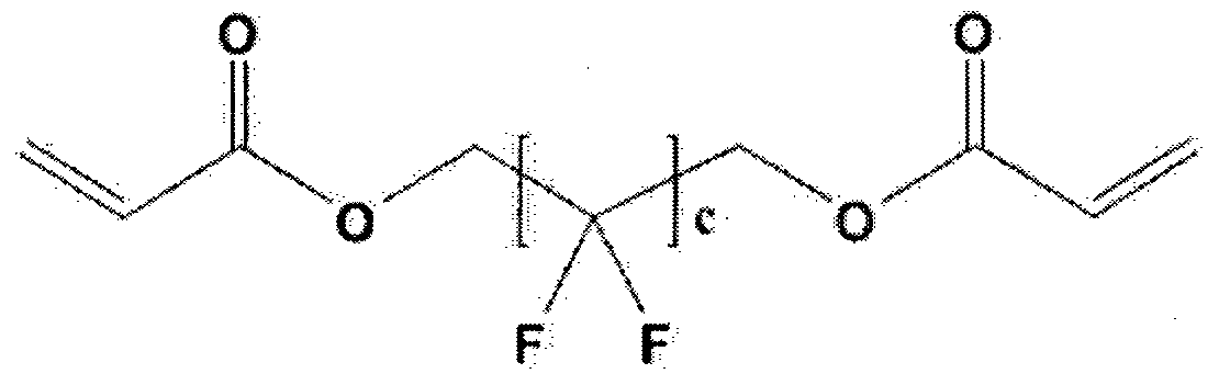
상기 화학식 2에서 c는 1 내지 10의 정수이다. In Formula 2 c is an integer of 1 to 10.
[화학식 3]
 [Formula 3]
상기 화학식 3에서, d는 1 내지 11의 정수이다. In Formula 3, d is an integer of 1 to 11.
[화학식 4] [Formula 4]

[ 5] [5]

상기 화학식 5에서, f는 4 내지 10의 정수이다. In Formula 5, f is an integer of 4 to 10.
한편, 상기 저굴절층에는 상기 광반웅성 작용기를 포함한 함불소 화합물로부터 유래한 부분이 포함될 수 있다. On the other hand, the low refractive index layer may include a portion derived from the fluorine-containing compound including the photo-reflective functional group.
상기 광반웅성 작용기를 포함한 함불소 화합물에는 1이상의 광반웅성 작용기가 포함 또는 치환될 수 있으며, 상기 광반웅성 작용기는 빛의 조사에 의하여, 예를 들어 가시 광선 또는 자외선의 조사에 의하여 중합 반웅에 참여할 수 있는 작용기를 의미한다. 상기 광반응성 작용기는 빛의 조사에 의하여 중합 반웅에 참여할 수 있는 것으로 알려진 다양한 작용기를
포함할 수 있으며, 이의 구체적인 예로는 (메트)아크릴레이트기, 에폭사이드기 , 비닐기 (Vinyl ) 또는 싸이올기 (Thiol )를 들 수 있다. The fluorine-containing compound including the photoreactive functional group may include or replace one or more photoreactive functional groups, and the photoreactive functional groups may participate in the polymerization reaction by irradiation of light, for example, by irradiation of visible light or ultraviolet light. Means functional groups. The photoreactive functional groups are various functional groups known to be able to participate in the polymerization reaction by the irradiation of light. A specific example thereof may include a (meth) acrylate group, an epoxide group, a vinyl group (Vinyl), or a thiol group (Thiol).
상기 광반웅성 작용기를 포함한 함불소 화합물 각각은 2 , 000 내지 200 , 000, 바람직하게는 5 , 000 내지 100 , 000의 중량평균분자량 (GPC법에 의해 측정한 폴리스티렌 환산의 중량 평균 분자량)을 가질 수 있다. Each of the fluorine-containing compounds including the photo-banung functional group may have a weight average molecular weight (weight average molecular weight in terms of polystyrene measured by GPC method) of 2, 000 to 200, 000, preferably 5, 000 to 100, 000. have.
상기 광반웅성 작용기를 포함한 함불소 화합물의 중량평균분자량이 너무 작으면, 상기 광경화성 코팅 조성물에서 함불소 화합물들이 표면에 균일하고 효과적으로 배열하지 못하고 최종. 제조되는 저굴절층의 내부에 위치하게 되는데, 이에 따라 상기 저굴절층의 표면이 갖는 방오성이 저하되고 상기 저굴절층의 가교 밀도가 낮아져서 전체적인 강도나 내크스래치성 등의 기계적 물성이 저하될 수 있다. When the weight average molecular weight of the fluorine-containing compound including the photo-banung functional group is too small, the fluorine-containing compounds in the photocurable coating composition may not be uniformly and effectively arranged on the surface. It is located inside the low refractive layer to be manufactured, thereby reducing the antifouling property of the surface of the low refractive layer and lowering the crosslinking density of the low refractive layer can reduce the mechanical properties such as overall strength and scratch resistance have.
또한, 상기 광반웅성 작용기를 포함한 함불소 화합물의 중량평균분자량이 너무 높으면, 상기 광경화성 코팅 조성물에서 다른 성분들과의 상용성이 낮아질 수 있고, 이에 따라 최종 제조되는 저굴절층의 헤이즈가 높아지거나 광투과도가 낮아질 수 있으며, 상기 저굴절층의 강도 또한 저하될 수 있다. In addition, if the weight average molecular weight of the fluorine-containing compound including the photo-reflective functional group is too high, the compatibility with other components in the photocurable coating composition may be lowered, thereby increasing the haze of the low refractive layer to be produced Light transmittance may be lowered, and the strength of the low refractive index layer may also be lowered.
구체적으로, 상기 광반웅성 작용기를 포함한 함불소 화합물은 i ) 하나 이상의 광반웅성 작용기가 치환되고, 적어도 하나의 탄소에 1이상의 불소가 치환된 지방족 화합물 또는 지방족 고리 화합물; i i ) 1 이상의 광반응성 작용기로 치환되고, 적어도 하나의 수소가 불소로 치환되고, 하나 이상의 탄소가 규소로 치환된 헤테로 (hetero) 지방족 화합물 또는 헤테로 (hetero)지방족 고리 화합물; i i i ) 하나 이상의 광반웅성 작용기가 치환되고, 적어도 하나의 실리콘에 1이상의 불소가 치환된 폴리디알킬실록산계 고분자 (예를 들어, 폴리디메틸실록산계 고분자) ; iv) 1 이상의 광반웅성 작용기로 치환되고 적어도 하나의 수소가 불소로 치환된 폴리에테르 화합물, 또는 상기 i ) 내지 iv) 중 2이상의 흔합물 또는 이들의 공중합체를 들 수 있다. Specifically, the fluorine-containing compound including the photo-cyclic functional group is i) an aliphatic compound or aliphatic ring compound in which at least one photo-cyclic functional group is substituted, at least one fluorine is substituted in at least one carbon; i i) a heteroaliphatic compound or a heteroaliphatic ring compound substituted with one or more photoreactive functional groups, at least one hydrogen substituted with fluorine, and one or more carbons substituted with silicon; i i i) polydialkylsiloxane polymers (eg, polydimethylsiloxane polymers) in which at least one photoreactive functional group is substituted and at least one fluorine is substituted in at least one silicon; iv) a polyether compound substituted with at least one photoreactive functional group and at least one hydrogen is substituted with fluorine, or a mixture of two or more of the above i) to iv) or a copolymer thereof.
상기 광경화성 코팅 조성물은 상기 광중합성 화합물 100중량부에 대하여 상기 광반웅성 작용기를 포함한 함불소 화합물 20 내지 300중량부를 포함할 수 있다.
상기 광중합성 화합물 대비 상기 광반응성 작용기를 포함한 함불소 화합물이 과량으로 첨가되는 경우 상기 구현예의 광경화성 코팅 조성물의 코팅성이 저하되거나 상기 광경화성 코팅 조성물로부터 얻어진 저굴절층이 층분한 내구성이나 내스크래치성을 갖지 못할 수 있다. 또한, 상기 광중합성 화합물 대비 상기 광반웅성 작용기를 포함한 함불소 화합물의 양이 너무 작으면, 상기 광경화성 코팅 조성물로부터 얻어진 저굴절층이 층분한 방오성이나 내스크래치성 등의 기계적 물성을 갖지 못할 수 있다. 상기 광반웅성 작용기를 포함한 함불소 화합물은 규소 또는 규소 화합물을 더 포함할 수 있다. 즉, 상기 광반응성 작용기를 포함한 함불소 화합물은 선택적으로 내부에 규소 또는 규소 화합물을 함유할 수 있고, 구체적으로 상기 광반웅성 작용기를 포함한 함불소 화합물 중 규소의 함량은 0. 1 중량 % 내지 20중량%일 수 있다. The photocurable coating composition may include 20 to 300 parts by weight of the fluorine-containing compound including the photobanung functional group based on 100 parts by weight of the photopolymerizable compound. When the fluorine-containing compound containing the photoreactive functional group is added in excess of the photopolymerizable compound, the coating property of the photocurable coating composition of the embodiment is lowered or the low refractive layer obtained from the photocurable coating composition is more durable or scratch resistant. You may not have a last name. In addition, when the amount of the fluorine-containing compound containing the photo-reflective functional group relative to the photopolymerizable compound is too small, the low refractive index layer obtained from the photocurable coating composition may not have mechanical properties such as layered antifouling or scratch resistance. . The fluorine-containing compound including the photobanung functional group may further include silicon or a silicon compound. That is, the fluorine-containing compound including the photoreactive functional group may optionally contain a silicon or silicon compound therein, specifically, the content of silicon in the fluorine-containing compound containing the photo-banung functional group is from 0.01% by weight to 20% by weight May be%.
상기 광반응성 작용기를 포함한 함불소 화합물에 포함되는 규소는 상기 구현예의 광경화성 코팅 조성물에 포함되는 다른 성분과의 상용성을 높일 수 있으며 이에 따라 최종 제조되는 굴절층에 헤이즈 (haze)가 발생하는 것을 방지하여 투명도를 높이는 역할을 할 수 있다. 한편, 상기 광반응성 작용기를 포함한 함불소 화합물 중 규소의 함량이 너무 커지면, 상기 광경화성 코팅 조성물에 포함된 다른 성분과 상기 함불소 화합물 간의 상용성이 오히려 저하될 수 있으며, 이에 따라 최종 제조되는 저굴절층이나 반사 방지 필름이 층분한 투광도나 반사 방지 성능을 갖지 못하여 표면의 방오성 또한 저하될 수 있다. Silicon contained in the fluorine-containing compound including the photoreactive functional group can increase the compatibility with other components included in the photocurable coating composition of the embodiment, and accordingly, haze is generated in the final refractive layer It can play a role of increasing transparency by preventing. On the other hand, when the content of silicon in the fluorine-containing compound containing the photoreactive functional group is too large, the compatibility between the other components included in the photocurable coating composition and the fluorine-containing compound may be rather lowered, thereby resulting in low Since the refractive layer or the antireflection film does not have sufficient light transmittance or antireflection performance, the antifouling property of the surface may also be reduced.
상기 저굴절층은 상기 광중합성 화합물의 (공)중합체 100중량부 대비 상기 중공형 무기 나노 입자 10 내지 400 중량부 및 상기 솔리드형 무기 나노 입자 10 내지 400중량부를 포함할 수 있다. The low refractive layer may include 10 to 400 parts by weight of the hollow inorganic nanoparticles and 10 to 400 parts by weight of the solid inorganic nanoparticles relative to 100 parts by weight of the (co) polymer of the photopolymerizable compound.
상기 저굴절층 중 상기 중공형 무기 나노 입자 및 솔리드형 무기 나노 입자의 함량이 과다해지는 경우, 상기 저굴절층 제조 과정에서 상기 중공형 무기 나노 입자 및 솔리드형 무기 나노 입자 간의 상분리가 충분히 일어나지 않고 흔재되어 반사율이 높아질 수 있으며, 표면 요철이 과다하게 발생하여 방오성이 저하될 수 있다. 또한, 상기 저굴절층 중 상기 중공형 무기 나노 입자 및 솔리드형 무기 나노 입자의 함량이 과소한 경우, 상기
하드 코팅층 및 상기 저굴절층 간의 계면으로부터 가까운 영역에 상기 솔리드형 무기 나노 입자 중 다수가 위치하기 어려울 수 있으며, 상기 저굴절층의 반사율은 크게 높아질 수 있다. When the content of the hollow inorganic nanoparticles and solid inorganic nanoparticles in the low refractive index layer is excessive, phase separation between the hollow inorganic nanoparticles and the solid inorganic nanoparticles does not occur sufficiently in the manufacturing process of the low refractive index layer As a result, the reflectance may be increased, and surface irregularities may occur excessively, thereby degrading antifouling properties. In addition, when the content of the hollow inorganic nanoparticles and solid-type inorganic nanoparticles in the low refractive index layer is too small, Many of the solid inorganic nanoparticles may be difficult to locate in an area close to an interface between the hard coating layer and the low refractive layer, and the reflectance of the low refractive layer may be significantly increased.
상기 저굴절층은 Iran 내지 300 nm , 또는 50nm 내지 200 ηπι의 두께를 가질 수 있다. The low refractive index layer may have a thickness of Iran to 300 nm, or 50 nm to 200 ηπι.
한편 , 상기 하드 코팅층으로는 통상적으로 알려진 하드 코팅층을 큰 제한 없이 사용할 수 있다. On the other hand, as the hard coating layer, a conventionally known hard coating layer can be used without great limitation.
상기 하드 코팅층의 일 예로서, 광경화성 수지를 포함하는 바인더 수지 및 상기 바인더 수지에 분산된 유기 또는 무기 미립자;를 포함하는 하드 코팅층을 들 수 있다. 상기 하드코팅층에 포함되는 광경화형 수지는 자외선 등의 광이 조사되면 중합 반웅을 일으킬 수 있는 광경화형 화합물의 중합체로서, 당업계에서 통상적인 것일 수 있다. 구체적으로, 상기 광경화성 수지는 우레탄 아크릴레이트 올리고머, 에폭사이드 아크릴레이트 을리고머, 폴리에스터 아크릴레이트, 및 폴리에테르 아크릴레이트로 이루어진 반웅성 아크릴레이트 올리고머 군; 및 디펜타에리스리를 핵사아크릴레이트, 디펜타에리스리를 하이드록시 펜타아크릴레이트, 펜타에리스리를 테트라아크릴레이트, 펜타에리스리를 트리아크릴레이트, 트리메틸렌 프로필 트리아크릴레이트, 프로폭시레이티드 글리세를 트리아크릴레이트, 트리메틸프로판 에록시 트리아크릴레이트, 1,6-핵산디올디아크릴레이트, 프로폭시레이티드 글리세로 트리아크릴레이트, 트리프로필렌 글리콜 디아크릴레이트, 및 에틸렌글리콜 디아크릴레이트로 이루어진 다관능성 아크릴레이트 단량체 군에서 선택되는 1 종 이상을 포함할 수 있다. As an example of the said hard coat layer, the hard coat layer containing the binder resin containing photocurable resin, and the organic or inorganic fine particle disperse | distributed to the said binder resin; The photocurable resin included in the hard coat layer is a polymer of a photocurable compound that may cause polymerization reaction when irradiated with light such as ultraviolet rays, and may be conventional in the art. Specifically, the photocurable resin is a semi-aromatic acrylate oligomer group consisting of a urethane acrylate oligomer, epoxide acrylate oligomer, polyester acrylate, and polyether acrylate; And dipentaerythritol nucleoacrylate, dipentaerythroxy hydroxy pentaacrylate, pentaerythriri tetraacrylate, pentaerythriri triacrylate, trimethylene propyl triacrylate, propoxylated glycerol Multifunctional acryl consisting of triacrylate, trimethylpropane ethoxy triacrylate, 1,6-nucleic acid diol diacrylate, propoxylated glycerol triacrylate, tripropylene glycol diacrylate, and ethylene glycol diacrylate It may include one or more selected from the group of the rate monomers.
상기 유기 또는 무기 미립자는 입경의 구체적으로 한정되는 것은 아니나, 예들 들어 유기 미립자는 1 내지 .10 의 입경을 가질 수 있으며, 상기 무기 입자는 1 ran 내지 500 ran , 또는 Iran 내지 300ran의 입경을 가질 수 있다. 상기 유기 또는 무기 미립자는 입경은 부피 평균 입경으로 정의될 수 있다.
또한, 상기 하드 코팅 필름에 포함되는 유기 또는 무기 미립자의 구체적인 예가 한정되는 것은 아니나, 예를 들어 상기 유기 또는 무기 미립자는 아크릴계 수지, 스티렌계 수지, 에폭사이드 수지 및 나일론 수지로 이루어진 유기 미립자이거나 산화규소, 이산화티탄, 산화인듐, 산화주석, 산화지르코늄 및 산화아연으로 이루어진 무기 미립자일 수 있다. 상기 하드 코팅층의 바인더 수지는 중량평균분자량 10 , 000 이상의 고분자량 (공)중합체를 더 포함할 수 있다. 상기 고분자량 (공)중합체는 셀를로스계 폴리머, 아크릴계 폴리머, 스티렌계 폴리머, 에폭사이드계 폴리머, 나일론계 폴리머, 우레탄계 폴리머, 및 폴리올레핀계 폴리머로 이루어진 군에서 선택되는 1 종 이상일 수 있다. 한편, 상기 하드 코팅 필름의 또 다른 일 예로서, 광경화성 수지의 바인더 수지; 및 상기 바인더 수지에 분산된 대전 방지제를 포함하는 하드 코팅 필름을 들 수 있다. The organic or inorganic fine particles are not particularly limited in particle size, for example, the organic fine particles may have a particle size of 1 to .10, and the inorganic particles may have a particle size of 1 ran to 500 ran or Iran to 300 ran. have. The particle size of the organic or inorganic fine particles may be defined as a volume average particle diameter. In addition, specific examples of the organic or inorganic fine particles included in the hard coating film are not limited. For example, the organic or inorganic fine particles may be organic fine particles made of acrylic resin, styrene resin, epoxide resin and nylon resin or silicon oxide. It may be an inorganic fine particle consisting of titanium dioxide, indium oxide, tin oxide, zirconium oxide and zinc oxide. The binder resin of the hard coating layer may further include a high molecular weight (co) polymer having a weight average molecular weight of 10, 000 or more. The high molecular weight (co) polymer may be one or more selected from the group consisting of cellulose polymers, acrylic polymers, styrene polymers, epoxide polymers, nylon polymers, urethane polymers, and polyolefin polymers. On the other hand, as another example of the hard coating film, a binder resin of a photocurable resin; And the hard coat film containing the antistatic agent disperse | distributed to the said binder resin is mentioned.
상기 하드코팅층에 포함되는 광경화형 수지는 자외선 등의 광이 조사되면 중합 반웅을 일으킬 수 있는 광경화형 화합물의 중합체로서, 당업계에서 통상적인 것일 수 있다. 다만, 바람직하게는, 상기 광경화형 화합물은 다관능성 (메트)아크릴레이트계 단량체 또는 올리고머일 수 있고, 이때 (메트)아크릴레이트계 관능기의 수는 2 내지 10, 바람직하게는 2 내지 8, 보다 바람직하게는 2 내지 7인 것이, 하드코팅층의 물성 확보 측면에서 유리하다. 보다 바람직하게는, 상기 광경화형 화합물은 펜타에리스리를 트리 (메트)아크릴레이트, 펜타에리스리를 테트라 (메트)아크릴레이트, 디펜타에리스리를 펜타 (메트)아크릴레이트, 디펜타에리스리를 핵사 (메트)아크릴레이트, 디펜타에리스리景 헵타 (메트)아크릴레이트, 트리펜타에리스리를 헵타 (메트)아크릴레이트, 트릴렌 디이소시아네이트, 자일렌 디이소시아네이트, 핵사메틸렌 디이소시아네이트, 트리메틸을프로관 트리 (메트)아크릴레이트, 및 트리메틸을프로판 폴리에록시 트리 (메트)아크릴레이트로 이루어진 군에서 선택되는 1종 이상일 수 있다. 상기 대전 방지제는 4급 암모늄염 화합물; 피리디늄염; 1 내지 3개의 아미노기를 갖는 양이온성 화합물; 설폰산 염기, 황산 에스테르 염기, 인산
에스테르 염기, 포스폰산 염기 등의 음이온성 화합물; 아미노산계 또는 아미노 황산 에스테르계 화합물 등의 양성 화합물; 이미노 알코올계 화합물, 글리세린계 화합물, 폴리에틸렌 글리콜계 화합물 등의 비이온성 화합물; 주석 또는 티타늄 등을 포함한 금속 알콕사이드 화합물 등의 유기 금속 화합물; 상기 유기 금속 화합물의 아세틸아세토네이트 염 등의 금속 킬레이트 화합물; 이러한 화합물들의 2종 이상의 반웅물 또는 고분자화물; 이러한 화합물들의 2종 이상의 흔합물일 수 있다. 여기서, 상기 4급 암모늄염 화합물은 분자 내에 1개 이상의 4급 암모늄염기를 가지는 화합물일 수 있으며, 저분자형 또는 고분자형을 제한 없이 사용할 수 있다. 또한, 상기 대전 방지제로는 도전성 고분자와 금속 산화물 미립자도 사용할 수 있다. 상기 도전성 고분자로는 방향족 공액계 폴리 (파라페닐렌), 헤테로고리식 공액계의 폴리피를, 폴리티오펜, 지방족 공액계의 폴리아세틸렌, 헤테로 원자를 함유한 공액예의 폴리아닐린, 흔합 형태 공액계의 폴리 (페닐렌 비닐렌), 분자중에 복수의 공액 사슬을 갖는 공액계인 복쇄형 공액계 화합물, 공액 고분자 사슬을 포화 고분자에 그래프트 또는 블록 공중합시킨 도전성 복합체 등이 있다. 또한, 상기 금속 산화물 미립자로는 산화 아연, 산화 안티몬, 산화 주석, 산화 세륨, 인듐 주석 산화물, 산화 인듐, 산화 알루니뮴, 안티몬 도핑된 산화 주석, 알루미늄 도핑된 산화 아연 등을 들 수 있다. The photocurable resin included in the hard coat layer is a polymer of a photocurable compound that may cause polymerization reaction when irradiated with light such as ultraviolet rays, and may be conventional in the art. However, preferably, the photocurable compound may be a polyfunctional (meth) acrylate monomer or oligomer, wherein the number of (meth) acrylate functional groups is 2 to 10, preferably 2 to 8, more preferably Preferably it is 2 to 7, it is advantageous in terms of securing physical properties of the hard coating layer. More preferably, the photocurable compound is nucleated pentaerythritol tri (meth) acrylate, pentaerythriri tetra (meth) acrylate, dipentaerythritol penta (meth) acrylate, dipentaerythride Hepta (meth) acrylate, tripentaerythr (hepta (meth) acrylate, triylene diisocyanate, xylene diisocyanate, nusamethylene diisocyanate, trimethyl) (Meth) acrylate and trimethyl may be one or more selected from the group consisting of propane polyethoxy tri (meth) acrylate. The antistatic agent is a quaternary ammonium salt compound; Pyridinium salts; Cationic compounds having from 1 to 3 amino groups; Sulfonic acid base, sulfate ester base, phosphoric acid Anionic compounds such as ester bases and phosphonic acid bases; Positive compounds, such as an amino acid type or amino sulfate ester type compound; Nonionic compounds such as imino alcohol compounds, glycerin compounds, and polyethylene glycol compounds; Organometallic compounds such as metal alkoxide compounds including tin or titanium; Metal chelate compounds such as acetylacetonate salts of the organometallic compounds; Two or more semi-ungmuls or polymerized compounds of these compounds; It may be a combination of two or more of these compounds. Here, the quaternary ammonium salt compound may be a compound having one or more quaternary ammonium salt groups in the molecule, it can be used without limitation low molecular type or polymer type. Moreover, as said antistatic agent, a conductive polymer and metal oxide fine particles can also be used. Examples of the conductive polymer include an aromatic conjugated poly (paraphenylene), a polycyclic ring having a heterocyclic conjugate, polythiophene, a polyacetylene having an aliphatic conjugate, and a polyaniline conjugated with a hetero atom. Poly (phenylene vinylene), a conjugated compound having a plurality of conjugated chains in a molecule, and a conjugated conjugated compound, a conductive composite obtained by grafting or block copolymerizing a conjugated polymer chain to a saturated polymer. In addition, the metal oxide fine particles include zinc oxide, antimony oxide, tin oxide, cerium oxide, indium tin oxide, indium oxide, aluminium oxide, antimony doped tin oxide, aluminum doped zinc oxide, and the like.
상기 광경화성 수지의 바인더 수지; 및 상기 바인더 수지에 분산된 대전 방지제를 포함하는 하드 코팅 필름은 알콕시 실란계 올리고머 및 금속 알콕사이드계 올리고머로 이루어진 군에서 선택되는 1종 이상의 화합물을 더 포함할 수 있다. Binder resin of the photocurable resin; And an antistatic agent dispersed in the binder resin may further include one or more compounds selected from the group consisting of alkoxy silane oligomers and metal alkoxide oligomers.
상기 알콕시 실란계 화합물은 당업계에서 통상적인 것일 수 있으나, 바람직하게는 테트라메특시실란, 테트라에록시실란, 테트라이소프로폭시실란, 메틸트리메특시실란, 메틸트리에록시실란, 메타크릴록시프로필트리메록시실란, 글리시독시프로필 트리메록시실란, 및 글리시독시프로필 트리에록시실란으로 이루어진 군에서 선택되는 1종 이상의 화합물일 수 있다. The alkoxy silane compound may be conventional in the art, but preferably tetramethoxysilane, tetraethoxysilane, tetraisopropoxysilane, methyltrimethoxysilane, methyltriethoxysilane, methacryloxypropyl It may be at least one compound selected from the group consisting of trimethoxysilane, glycidoxypropyl trimethoxysilane, and glycidoxypropyl triethoxysilane.
또한, 상기 금속 알콕사이드계 올리고머는 금속 알콕사이드계 화합물
및 물을 포함하는 조성물의 졸-겔 반웅을 통해 제조할 수 있다. 상기 졸-겔 반웅은 전술한 알콕시 실란계 올리고머의 제조 방법에 준하는 방법으로 수행할 수 있다. In addition, the metal alkoxide-based oligomer is a metal alkoxide-based compound And it can be prepared through the sol-gel reaction of the composition comprising water. The sol-gel reaction can be carried out by a method similar to the method for producing an alkoxy silane oligomer described above.
다만, 상기 금속 알콕사이드계 화합물은 물과 급격하게 반응할 수 있으므로, 상기 금속 알콕사이드계 화합물을 유기용매에 희석한 후 물을 천천히 드로핑하는 방법으로 상기 졸-겔 반웅을 수행할 수 있다. 이때, 반웅 효율 등을 감안하여, 물에 대한 금속 알콕사이드 화합물의 몰비 (금속이온 기준)는 3 내지 170인 범위 내에서 조절하는 것이 바람직하다. However, since the metal alkoxide compound may react with water rapidly, the sol-gel reaction may be performed by diluting the metal alkoxide compound in an organic solvent and slowly dropping water. At this time, in consideration of reaction efficiency, the molar ratio of the metal alkoxide compound to water (based on metal ions) is preferably adjusted within the range of 3 to 170.
여기서, 상기 금속 알콕사이드계 화합물은 티타늄 테트라- 이소프로폭사이드, 지르코늄 이소프로폭사이드, 및 알루미늄 이소프로폭사이드로 이루어진 군에서 선택되는 1종 이상의 화합물일 수 있다. Here, the metal alkoxide-based compound may be at least one compound selected from the group consisting of titanium tetra-isopropoxide, zirconium isopropoxide, and aluminum isopropoxide.
상기 하드 코팅층은 O . l/zm 내지 100 의 두께를 가질 수 있다. The hard coating layer is O. It may have a thickness of l / zm to 100.
상기 하드 코팅층의 다른 일면에 결합된 기재를 더 포함할 수 있다. 상기 기재의 구체적인 종류나 두께는 크게 한정되는 것은 아니며, 저굴절층 또는 반사 방지 필름의 제조에 사용되는 것으로 알려진 기재를 큰 제한 없이 사용할 수 있다. 한편, 상기 구현예의 반사 방지 필름은, 광경화형 화합물 또는 이의 It may further include a substrate bonded to the other side of the hard coating layer. The specific kind or thickness of the substrate is not particularly limited, and a substrate known to be used in the manufacture of a low refractive index layer or an antireflection film can be used without great limitation. On the other hand, the anti-reflection film of the embodiment, a photocurable compound or its
(공)중합체 광반웅성 작용기를 포함한 함불소 화합물, 광개시제, 중공형 무기 나노 입자 및 솔리드형 무기 나노 입자를 포함한 저굴절층 형성용 수지 조성물을 하드 코팅층 상에 도포하고 35 °C 내지 100 °C , 또는 40 °C 내지 80 0C의 온도에서 건조하는 단계; 및 상기 수지 조성물의 건조물을 광경화하는 단계;를 포함하는 반사 방지 필름의 제조 방법을 통하여 제공될 수 있다. A resin composition for forming a low refractive index layer including a fluorine-containing compound, a photoinitiator, hollow inorganic nanoparticles, and solid inorganic nanoparticles, including a (co) polymer photoreactive functional group, is coated on a hard coating layer, and then applied at 35 ° C to 100 ° C, Or drying at a temperature of 40 ° C. to 80 0 C; And photocuring the dried material of the resin composition.
구체적으로, 상기 반사 방지 필름의 제조 방법에 의하여 제공되는 반사 방지 필름은 저굴절층 내에서 중공형 무기 나노 입자 및 솔리드형 무기 나노 입자가 서로 구분될 수 있도록 분포시키고 이에 따라 낮은
반사율 및 높은 투광율을 가지면서 높은 내스크래치성 및 방오성을 동시에 구현할 수 있다. Specifically, the anti-reflection film provided by the method for manufacturing the anti-reflection film is distributed in the low refractive layer so that the hollow inorganic nanoparticles and the solid inorganic nanoparticles can be distinguished from each other and thus low With high reflectivity and high light transmittance, high scratch resistance and antifouling property can be realized simultaneously.
보다 상세하게는, 상기 반사 방지 필름은 하드 코팅층; 및 상기 하드 코팅층의 일면에 형성되며, 바인더 수지와 상기 바인더 수지에 분산된 중공형 무기 나노 입자 및 솔리드형 무기 나노 입자를 포함하는 저굴절층;을 포함하며, 상기 하드 코팅층 및 상기 저굴절층 간의 계면으로부터 상기 저굴절층 전체 두께 50% 이내에 상기 솔리드형 무기 나노 입자 전체 중 70부피 ¾ 이상이 존재할 수 있다. More specifically, the anti-reflection film is a hard coating layer; And a low refractive index layer formed on one surface of the hard coating layer, the binder resin and hollow inorganic nanoparticles dispersed in the binder resin and solid inorganic nanoparticles; and between the hard coating layer and the low refractive layer. 70 volume ¾ or more of the entire solid inorganic nanoparticle may be present within 50% of the total thickness of the low refractive layer from an interface.
또한, 상기 중공형 무기 나노 입자 전체 중 30 부피 % 이상이 상기 솔리드형 무기 나노 입자 전체 보다 상기 하드 코팅층 및 상기 저굴절층 간의 계면으로부터 상기 저굴절층의 두께 방향으로 보다 먼 거리에 존재할 수 있다. In addition, at least 30% by volume of the entire hollow inorganic nanoparticles may be present at a greater distance in the thickness direction of the low refractive layer than the interface between the hard coating layer and the low refractive layer than the entire solid inorganic nanoparticles.
또한, 상기 하드 코팅층과 상기 저굴절층의 계면으로부터 상기 저굴절층 전체 두께 30% 이내에 상기 솔리드형 무기 나노 입자 전체 중 70 부피 % 이상이 존재할 수 있다. 또한, 상기 하드 코팅층과 상기 저굴절층의 계면으로부터 상기 저굴절층 전체 두께 30% 초과의 영역에 상기 중공형 무기 나노 입자 전체 중 70 부피 ¾> 이상이 존재할 수 있다. In addition, 70% by volume or more of the total solid inorganic nanoparticles may be present within 30% of the total thickness of the low refractive layer from the interface between the hard coating layer and the low refractive layer. In addition, at least 70% by volume ¾> of the entire hollow inorganic nanoparticle may be present in an area of more than 30% of the total thickness of the low refractive index layer from an interface between the hard coating layer and the low refractive index layer.
또한, 상기 반사 방지 필름의 제조 방법에 의하여 제공되는 반사 방지 필름에서, 상기 저굴절층은 상기 솔리드형 무기 나노 입자 전체 중 70중량 % 이상이 포함된 제 1층과 상기 중공형 무기 나노 입자 전체 중 70중량 % 이상이 포함된 제 2층을 포함할 수 있으며, 상기 제 1층이 제 2층에 비하여 상기 하드 코팅층 및 상기 저굴절층 간의 계면에 보다 가까이 위치할 수 있다. In addition, in the anti-reflection film provided by the method for producing the anti-reflection film, the low refractive index layer of the first layer and at least 70% by weight of the entire solid inorganic nanoparticles and the entire hollow inorganic nanoparticles It may include a second layer containing more than 70% by weight, the first layer may be located closer to the interface between the hard coating layer and the low refractive layer than the second layer.
상기 저굴절층은 광경화형 화합물 또는 이의 (공)중합체, 광반웅성 작용기를 포함한 함불소 화합물, 광개시제, 중공형 무기 나노 입자 및 솔리드형 무기 나노 입자를 포함한 저굴절층 형성용 수지 조성물을 하드 코팅층 상에 도포하고 35 °C 내지 100 °C , 또는 40 °C 내지 80 °C의 온도에서 건조함으로서 형성될 수 있다. The low refractive index layer comprises a photocurable compound or a (co) polymer thereof, a fluorine-containing compound including photoreactive functional groups, a photoinitiator, hollow inorganic nanoparticles, and a resin composition for forming a low refractive layer including solid inorganic nanoparticles on a hard coating layer It can be formed by applying to and drying at a temperature of 35 ° C to 100 ° C, or 40 ° C to 80 ° C.
상기 하드 코팅층 상에 도포된 저굴절층 형성용 수지 조성물을
건조하는 온도가 35°C 미만이면, 상기 형성되는 저굴절층이 갖는 방오성이 크게 저하될 수 있다. 또한, 상기 하드 코팅층 상에 도포된 저굴절층 형성용 수지 조성물을 건조하는 온도가 100oC 초과이면, 상기 저굴절층 제조 과정에서 상기 중공형 무기 나노 입자 및 솔리드형 무기 나노 입자 간의 상분리가 층분히 일어나지 않고 흔재되어 상기 저굴절층의 내스크래치성 및 방오성이 저하될 뿐만 아니라 반사율도 크게 높아질 수 있다. A resin composition for forming a low refractive index layer coated on the hard coating layer If the drying temperature is less than 35 ° C., the antifouling property of the formed low refractive index layer may be greatly reduced. In addition, if the temperature of drying the resin composition for forming the low refractive index layer applied on the hard coating layer is more than 100 o C, phase separation between the hollow inorganic nanoparticles and solid inorganic nanoparticles in the low refractive layer manufacturing process layer It is not common to occur, so that the scratch resistance and antifouling property of the low refractive index layer may be lowered, and the reflectance may be greatly increased.
상기 하드 코팅층 상에 도포된 저굴절층 형성용 수지 조성물을 건조하는 과정에서 상기 건조 온도와 함께 상기 솔리드형 무기 나노 입자 및 중공형 무기 나노 입자 간의 밀도 차이를 조절함으로서 상술한 특성을 갖는 저굴절층을 형성할 수 있다. 상기 솔리드형 무기 나노 입자가 상기 중공형 무기 나노 입자에 비하여 0.50 g/cin3 이상 높은 밀도를 가질 수 있으며, 이러한 밀도 차이로 인하여 상기 하드 코팅층 상에 형성되는 저굴절층에서 상기 솔리드형 무기 나노 입자가 하드 코팅층 쪽에 보다 가까운 쪽에 위치할 수 있다. Low refractive index layer having the above-described characteristics by controlling the density difference between the solid inorganic nanoparticles and the hollow inorganic nanoparticles with the drying temperature in the process of drying the resin composition for forming the low refractive index layer applied on the hard coating layer Can be formed. The solid inorganic nanoparticles may have a density of 0.50 g / cin 3 or more higher than that of the hollow inorganic nanoparticles, and due to the density difference, the solid inorganic nanoparticles in the low refractive layer formed on the hard coating layer. May be located closer to the hard coating layer.
구체적으로, 상기 솔리드형 무기 나노 입자는 2.00 g/cin3 내지 4.00 g/cirf의 밀도를 갖고, 상기 중공형 무기 나노 입자는 1.50 g/cm3 내지 3. 50 g/cirf의 밀도를 가질 수 있다. Specifically, the solid inorganic nanoparticles may have a density of 2.00 g / cin 3 to 4.00 g / cirf, and the hollow inorganic nanoparticles may have a density of 1.50 g / cm 3 to 3.50 g / cirf. .
한편, 상기 하드 코팅층 상에 도포된 저굴절층 형성용 수지 조성물을 35 °C 내지 100 0C의 온도에서 건조하는 단계는 10초 내지 5분간, 또는 30초 내지 4분간 수행될 수 있다. On the other hand, the step of drying the resin composition for forming the low refractive index layer applied on the hard coating layer at a temperature of 35 ° C to 100 0 C may be performed for 10 seconds to 5 minutes, or 30 seconds to 4 minutes.
상기 건조 시간이 너무 짧은 경우, 상술한 상기 솔리드형 무기 나노 입자 및 중공형 무기 나노 입자 간의 상분리 현상이 층분히 일어나지 않을 수 있다. 이에 반하여, 상기 건조 시간이 너무 긴 경우, 상기 형성되는 저굴절층이 하드 코팅층을 침식할 수 있다. When the drying time is too short, phase separation between the solid inorganic nanoparticles and the hollow inorganic nanoparticles described above may not occur. On the contrary, when the drying time is too long, the formed low refractive index layer may erode the hard coating layer.
한편, 상기 저굴절층은 광경화형 화합물 또는 이의 (공)중합체, 광반웅성 작용기를 포함한 함불소 화합물 중공형 무기 나노 입자, 솔리드형 무기 나노 입자 및 광개시제를 포함한 광경화성 코팅 조성물로부터 제조될 수 있다.
상기 저굴절층은 상기 광경화성 코팅 조성물을 소정의 기재 상에 도포하고 도포된 결과물을 광경화함으로써 얻어질 수 있다. 상기 기재의 구체적인 종류나 두께는 크게 한정되는 것은 아니며, 저굴절층 또는 반사 방지 필름의 제조에 사용되는 것으로 알려진 기재를 큰 제한 없이 사용할 수 있다. Meanwhile, the low refractive layer may be prepared from a photocurable coating composition including a photocurable compound or a (co) polymer thereof, a fluorine-containing compound hollow inorganic nanoparticle, a solid inorganic nanoparticle, and a photoinitiator. The low refractive layer can be obtained by applying the photocurable coating composition on a predetermined substrate and photocuring the applied resultant. The specific kind or thickness of the substrate is not particularly limited, and a substrate known to be used in the manufacture of a low refractive index layer or an antireflection film can be used without great limitation.
상기 광경화성 코팅 조성물을 도포하는데 통상적으로 사용되는 방법 및 장치를 별 다른 제한 없이 사용할 수 있으며, 예를 들어, Meyer bar 등의 바 코팅법, 그라비아 코팅법, 2 rol l reverse 코팅법, vacuum s lot di e 코팅법, 2 rol l 코팅법 등을 사용할 수 있다. Methods and apparatuses conventionally used to apply the photocurable coating composition may be used without particular limitation, for example, bar coating method such as Meyer bar, gravure coating method, 2 rol l reverse coating method, vacuum s lot die coating, 2 roll coating, and the like can be used.
상기 저굴절층은 lnm 내지 300 nm , 또는 50nm 내지 200 nm의 두께를 가질 수 있다. 이에 따라, 상기 소정의 기재 상에 도포되는 상기 광경화성 코팅 조성물의 두께는 약 lnm 내지 300 nm , 또는 50nm 내지 200 nm일 수 있다. The low refractive layer may have a thickness of lnm to 300 nm, or 50nm to 200 nm. Accordingly, the thickness of the photocurable coating composition applied on the predetermined substrate may be about lnm to 300 nm, or 50nm to 200 nm.
상기 광경화성 코팅 조성물을 광경화 시키는 단계에서는 200~400nm파장의 자외선 또는 가시 광선을 조사할 수 있고, 조사시 노광량은 100 내지 4 , 000 mJ/cin2 이 바람직하다. 노광 시간도 특별히 한정되는 것이 아니고, 사용 되는 노광 장치, 조사 광선의 파장 또는 노광량에 따라 적절히 변화시킬 수 있다. In the step of photocuring the photocurable coating composition may be irradiated with ultraviolet light or visible light having a wavelength of 200 ~ 400nm, the exposure amount is preferably 100 to 4,000 mJ / cin 2 when irradiated. Exposure time is not specifically limited, either, According to the exposure apparatus used, wavelength of an irradiation light, or exposure amount, it can change suitably.
또한, 상기 광경화성 코팅 조성물을 광경화 시키는 단계에서는 질소 대기 조건을 적용하기 위하여 질소 퍼징 등을 할 수 있다. In addition, in the step of photocuring the photocurable coating composition may be nitrogen purging to apply nitrogen atmospheric conditions.
상기 광경화형 화합물, 중공형 무기 나노 입자, 솔리드형 무기 나노 입자 및 광반웅성 작용기를 포함한 함불소 화합물에 관한 구체적인 내용은 상기 일 구현예의 반사 방지 필름에 관하여 상술한 내용을 포함한다. Details of the photocurable compound, the hollow inorganic nanoparticles, the solid inorganic nanoparticles, and the fluorine-containing compound including the photoreactive functional group include the above-described contents with respect to the anti-reflection film of the embodiment.
상기 중공형 무기 나노 입자 및 솔리드형 무기 나노 입자 각각은 소정의 분산매에 분산된 콜로이드상으로 조성물에 포함될 수 있다. 상기 중공형 무기 나노 입자 및 솔리드형 무기 나노 입자를 포함하는 각각의 콜로이드상은 분산매로 유기 용매를 포함할 수 있다. Each of the hollow inorganic nanoparticles and the solid inorganic nanoparticles may be included in the composition in the form of a colloid dispersed in a predetermined dispersion medium. Each colloidal phase including the hollow inorganic nanoparticles and the solid inorganic nanoparticles may include an organic solvent as a dispersion medium.
상기 광경화성 코팅 조성물 중 상기 중공형 무기 나노 입자 및 솔리드형 무기 나노 입자 각각의 함량 범위나 상기 광경화성 코팅 조성물의 점도 등을 고려하여 상기 중공형 무기 나노 입자 및 솔리드형 무기 나노
입자 각각의 콜로이드 상 중 함량이 결정될 수 있으며, 예를 들어 상기 콜로이드상 중 상기 중공형 무기 나노 입자 및 솔리드형 무기 나노 입자 각각의 고형분 함량은 5중량 % 내지 60중량 %일 수 있다. The hollow inorganic nanoparticles and the solid inorganic nanoparticles in consideration of the content range of the hollow inorganic nanoparticles and the solid inorganic nanoparticles or the viscosity of the photocurable coating composition in the photocurable coating composition. The content of the colloidal phase of each particle may be determined. For example, the solid content of each of the hollow inorganic nanoparticles and the solid inorganic nanoparticles in the colloidal phase may be 5% by weight to 60% by weight.
여기서, 상기 분산매 중 유기 용매로는 메탄올, 이소프로필알코을, 에틸렌글리콜, 부탄을 등의 알코올류; 메틸에틸케톤, 메틸이소부틸케톤 등의 케톤류; 를루엔, 자일렌 등의 방향족 탄화수소류; 디메틸포름아미드. 디메틸아세트아미드, N-메틸피를리돈 등의 아미드류; 초산에틸, 초산부틸, 감마부틸로락톤 등의 에스테르류; 테트라하이드로퓨란, 1 , 4-디옥산 등의 에테르류; 또는 이들의 흔합물이 포함될 수 있다. As the organic solvent in the dispersion medium, alcohols such as methanol, isopropyl alcohol, ethylene glycol and butane; Ketones such as methyl ethyl ketone and methyl isobutyl ketone; Aromatic hydrocarbons such as toluene and xylene; Dimethylformamide. Amides such as dimethylacetamide and N-methylpyridone; Esters such as ethyl acetate, butyl acetate and gamma butyrolactone; Ethers such as tetrahydrofuran and 1,4-dioxane; Or combinations thereof.
상기 광중합 개시제로는 광경화성 수지 조성물에 사용될 수 있는 것으로 알려진 화합물이면 크게 제한 없이 사용 가능하며, 구체적으로 벤조 페논계 화합물, 아세토페논계 화합물, 비이미다졸계 화합물, 트리아진계 화합물, 옥심계 화합물 또는 이들의 2종 이상의 흔합물을 사용할 수 있다. 상기 광중합성 화합물 100중량부에 대하여 , 상기 광중합 개시제는 1 내지 100중량부의 함량으로 사용될 수 있다. 상기 광중합 개시제의 양이 너무 작으면, 상기 광경화성 코팅 조성물의 광경화 단계에서 미경화되어 잔류하는 물질이 발행할 수 있다. 상기 광중합 개시제의 양이 너무 많으면, 미반응 개시제가 불순물로 잔류하거나 가교 밀도가 낮아져서 제조되는 필름의 기계적 물성이 저하되거나 반사율이 크게 높아질 수 있다. The photopolymerization initiator may be used without limitation as long as it is a compound known to be used in the photocurable resin composition. Specifically, a benzophenone compound, acetophenone compound, biimidazole compound, triazine compound, oxime compound, or the like may be used. Two or more kinds thereof can be used. With respect to 100 parts by weight of the photopolymerizable compound, the photopolymerization initiator may be used in an amount of 1 to 100 parts by weight. If the amount of the photopolymerization initiator is too small, an uncured material remaining in the photocuring step of the photocurable coating composition may be issued. If the amount of the photopolymerization initiator is too large, the unreacted initiator may remain as an impurity or have a low crosslinking density, thereby lowering mechanical properties or significantly increasing reflectance of the film.
한편, 상기 광경화성 코팅 조성물은 유기 용매를 더 포함할 수 있다. 상기 유기 용매의 비제한적인 예를 들면 케톤류, 알코올류, 아세테이트류 및 에테르류, 또는 이들의 2종 이상의 흔합물을 들 수 있다. 이러한 유기 용매의 구체적인 예로는, 메틸에틸케논, 메틸이소부틸케톤, 아세틸아세톤 또는 이소부틸케톤 등의 케톤류; 메탄올, 에탄올, 디아세톤알코올, n-프로판올, i-프로판올, n-부탄올, i-부탄올, 또는 t-부탄올 등의 알코올류; 에틸아세테이트, i-프로필아세테이트, 또는 폴리에틸렌글리콜 모노메틸에테르 아세테이트 등의 아세테이트류; 테트라하이드로퓨란 또는 프로필렌글라이콜 모노메틸에테르 등의 에테르류; 또는 이들의 2종 이상의 흔합물을 들 수 있다. Meanwhile, the photocurable coating composition may further include an organic solvent. Non-limiting examples of the organic solvents include ketones, alcohols, acetates and ethers, or combinations of two or more thereof. Specific examples of such organic solvents include ketones such as methyl ethyl kenone, methyl isobutyl ketone, acetylacetone or isobutyl ketone; Alcohols such as methanol, ethanol, diacetone alcohol, n-propanol, i-propanol, n-butanol, i-butanol, or t-butanol; Acetates such as ethyl acetate, i-propyl acetate, or polyethylene glycol monomethyl ether acetate; Ethers such as tetrahydrofuran or propylene glycol monomethyl ether; Or two or more kinds thereof.
상기 유기 용매는 상기 광경화성 코팅 조성물에 포함되는 각
성분들을 흔합하는 시기에 첨가되거나 각 성분들이 유기 용매에 분산 또는 흔합된 상태로 첨가되면서 상기 광경화성 코팅 조성물에 포함될 수 있다. 상기 광경화성 코팅 조성물 중 유기 용매의 함량이 너무 작으면, 상기 광경화성 코팅 조성물의 흐름성이 저하되어 최종 제조되는 필름에 즐무늬가 생기는 등 불량이 발생할 수 있다. 또한, 상기 유기 용매의 과량 첨가시 고형분 함량이 낮아져, 코팅 및 성막이 층분히 되지 않아서 필름의 물성이나 표면 특성이 저하될 수 있고, 건조 및 경화 과정에서 불량이 발생할 수 있다. 이에 따라, 상기 광경화성 코팅 조성물은 포함되는 성분들의 전체 고형분의 농도가 1중량 % 내지 50중량 %, 또는 2 내지 20중량%가 되도록 유기 용매를 포함할 수 있다. The organic solvent is each included in the photocurable coating composition The ingredients may be added at the time of mixing or may be included in the photocurable coating composition as each ingredient is added in a dispersed or mixed state in an organic solvent. When the content of the organic solvent in the photocurable coating composition is too small, defects may occur such that the flowability of the photocurable coating composition is lowered, resulting in a flaky pattern on the final film. In addition, when the excessive amount of the organic solvent is added, the solid content is lowered, coating and film formation are not divided, the physical properties and surface properties of the film may be lowered, and defects may occur in the drying and curing process. Accordingly, the photocurable coating composition may include an organic solvent such that the concentration of the total solids of the components included is 1% by weight to 50% by weight, or 2 to 20% by weight.
상기 하드 코팅층은 반사 방지 필름에 사용할 수 있는 것으로 알려진 재질이면 큰 제한 없이 사용할 수 있다. The hard coating layer may be used without any limitation as long as it is a material known to be used for the antireflection film.
상기 하드 코팅층 형성에 사용되는 성분에 관해서는 상기 일 구현예의 반사 방지 필름에 관하여 상술한 바와 같다. The components used to form the hard coat layer are the same as described above with respect to the antireflection film of the embodiment.
상기 하드 코팅층 형성용 고분자 수지 조성물을 도포하는데 통상적으로 사용되는 방법 및 장치를 별 다른 제한 없이 사용할 수 있으며, 예를 들어, Meyer bar 등의 바 코팅법, 그라비아 코팅법, 2 rol l reverse 코팅법, vacuum s lot di e 코팅법, 2 rol l 코팅법 등을 사용할 수 있다. Methods and apparatuses commonly used to apply the polymer resin composition for forming the hard coating layer may be used without particular limitation, for example, a bar coating method such as Meyer bar, gravure coating method, 2 rol l reverse coating method, vacuum s lot die coating, 2 roll coating, etc. may be used.
상기 하드 코팅층 형성용 고분자 수지 조성물을 광경화 시키는 단계에서는 200~400nm파장의 자외선 또는 가시 광선을 조사할 수 있고, 조사시 노광량은 100 내지 4, 000 mJ/cirf 이 바람직하다. 노광 시간도 특별히 한정되는 것이 아니고, 사용 되는 노광 장치 , 조사 광선의 파장 또는 노광량에 따라 적절히 변화시킬 수 있다. 또한, 상기 하드 코팅층 형성용 고분자 수지 조성물을 광경화 시키는 단계에서는 질소 대기 조건을 적용하기 위하여 질소 퍼징 등을 할 수 있다. In the step of photocuring the polymer resin composition for forming the hard coating layer may be irradiated with ultraviolet light or visible light having a wavelength of 200 ~ 400nm, the exposure dose is preferably 100 to 4, 000 mJ / cirf. Exposure time is not specifically limited, either, It can change suitably according to the exposure apparatus used, the wavelength of irradiation light, or an exposure amount. In addition, in the step of photocuring the polymer resin composition for forming the hard coating layer may be purged with nitrogen in order to apply nitrogen atmospheric conditions.
【발명의 효과】 【Effects of the Invention】
본 발명에 따르면, 낮은 반사율 및 높은 투광율을 가지면서 높은 내스크래치성 및 방오성을 동시에 구현할 수 있고 디스플레이 장치의 화면의 선명도를 높일 수 있는 반사 방지 필름 및 상기 반사 방지 필름의 제조 방법이 제공될 수 있다.
【도면의 간단한 설명】 According to the present invention, an anti-reflection film and a method of manufacturing the anti-reflection film can be provided that can simultaneously realize high scratch resistance and antifouling property while having a low reflectance and a high light transmittance and can increase the sharpness of the screen of the display device. . [Brief Description of Drawings]
도 1은 실시예 1의 반사 방지 방지 필름의 단면 TEM 사진을 나타낸 것이다. Figure 1 shows a cross-sectional TEM photograph of the anti-reflection film of Example 1.
도 2은 실시예 2의 반사 방지 방지 필름의 단면 TEM 사진을 나타낸 것이다. Figure 2 shows a cross-sectional TEM photograph of the anti-reflection film of Example 2.
도 3은 실시예 3의 반사 방지 방지 필름의 단면 TEM 사진을 나타낸 것이다. Figure 3 shows a cross-sectional TEM photograph of the anti-reflection film of Example 3.
도 4은 실시예 4의 반사 방지 방지 필름의 단면 TEM 사진을 나타낸 것이다. Figure 4 shows a cross-sectional TEM photograph of the anti-reflection film of Example 4.
도 5은 실시예 5의 반사 방지 방지 필름의 단면 TEM 사진을 나타낸 것이다. Figure 5 shows a cross-sectional TEM photograph of the anti-reflection film of Example 5.
도 6은 실시예 6의 반사 방지 방지 필름의 단면 TEM 사진을 나타낸 것이다. Figure 6 shows a cross-sectional TEM photograph of the anti-reflection film of Example 6.
도 7은 비교예 1의 반사 방지 방지 필름의 단면 TEM 사진을 나타낸 것이다. 7 shows a cross-sectional TEM photograph of the antireflective film of Comparative Example 1. FIG.
도 8은 비교예 2의 반사 방지 방지 필름의 단면 TEM 사진을 나타낸 것이다. 8 shows a cross-sectional TEM photograph of the antireflective film of Comparative Example 2. FIG.
도 9은 비교예 3의 반사 방지 방지 필름의 단면 TEM 사진을 나타낸 것이다. 9 shows a cross-sectional TEM photograph of the antireflective film of Comparative Example 3. FIG.
도 10은 실시예 1의 반사 방지 필름에 대하여 X선을 조사하여 얻어진 소각 산란에서 정의되는 산란 백터에 대한 산란 강도의 i0g값의 그래프를 나타낸 것이다. Figure 10 shows a graph of Example 1 i 0 g value of scattering intensity of the scattering vector, defined in the small angle scattering obtained by projecting the X-ray with respect to the antireflection film of the.
도 11은 실시예 2의 반사 방지 필름에 대하여 X선을 조사하여 얻어진 소각 산란에서 정의되는 산란 백터에 대한 산란 강도의 log값의 그래프를 나타낸 것이다. FIG. 11 shows a graph of log values of scattering intensity with respect to scattering vectors defined in small angle scattering obtained by irradiating X-rays to the antireflection film of Example 2. FIG.
도 12은 실시예 3의 반사 방지 필름에 대하여 X선을 조사하여 얻어진 소각 산란에서 정의되는 산란 백터에 대한 산란 강도의 log값의 그래프를 나타낸 것이다. FIG. 12: shows the graph of the log value of scattering intensity with respect to the scattering vector defined by the small angle scattering obtained by irradiating X-ray to the antireflection film of Example 3. FIG.
도 13은 실시예 4의 반사 방지 필름에 대하여 X선을 조사하여 얻어진 소각 산란에서 정의되는 산란 백터에 대한 산란 강도의 log값의 그래프를
나타낸 것이다. 13 is a graph of log values of scattering intensity for scattering vectors defined in small angle scattering obtained by irradiating X-rays to the antireflection film of Example 4; It is shown.
도 14은 실시예 5의 반사 방지 필름에 대하여 X선을 조사하여 얻어진 소각 산란에서 정의되는 산란 백터에 대한 산란 강도의 i0g값의 그래프를 나타낸 것이다. Figure 14 shows a plot of i 0 g value of scattering intensity of the scattering vector, defined in the small angle scattering obtained by projecting the X-ray with respect to the fifth embodiment of the anti-reflection film.
도 15은 실시예 6의 반사 방지 필름에 대하여 X선을 조사하여 얻어진 소각 산란에서 정의되는 산란 백터에 대한 산란 강도의 i0g값의 그래프를 나타낸 것이다. Figure 15 shows a graph of Example 6 i 0 g value of scattering intensity of the scattering vector, defined in the small angle scattering obtained by projecting the X-ray with respect to the antireflection film of the.
도 16은 비교예 1의 반사 방지 필름에 대하여 X선을 조사하여 얻어진 소각 산란에서 정의되는 산란 백터에 대한 산란 강도의 log값의 그래프를 나타낸 것이다. FIG. 16: shows the graph of the log value of the scattering intensity with respect to the scattering vector defined by the small angle scattering obtained by irradiating X-ray to the antireflection film of the comparative example 1. FIG.
도 17은 비교예 2의 반사 방지 필름에 대하여 X선을 조사하여 얻어진 소각 산란에서 정의되는 산란 백터에 대한 산란 강도의 log값의 그래프를 나타낸 것이다. FIG. 17: shows the graph of the log value of the scattering intensity with respect to the scattering vector defined by the small angle scattering obtained by irradiating X-ray to the antireflection film of the comparative example 2. FIG.
도 18은 비교예 3의 반사 방지 필름에 대하여 X선을 조사하여 얻어진 소각 산란에서 정의되는 산란 백터에 대한 산란 강도의 i0g값의 그래프를 나타낸 것이다. Figure 18 shows a plot of i 0 g value of scattering intensity of the scattering vector, defined in the small angle scattering obtained by projecting the X-ray with respect to the antireflection film of Comparative Example 3.
【발명올 실시하기 위한 구체적인 내용】 [Specific contents to carry out invention]
발명을 하기의 실시예에서 보다 상세하게 설명한다. 단, 하기의 실시예는 본 발명을 예시하는 것일 뿐, 본 발명의 내용이 하기의 실시예에 의하여 한정되는 것은 아니다. The invention is explained in more detail in the following examples. However, the following examples are merely to illustrate the invention, but the content of the present invention is not limited by the following examples.
<제조예 > <Production example>
제조예: 하드코팅 필름의 제조 Preparation Example: Preparation of Hard Coating Film
KY0EISHA사 염타입의 대전 방지 하드 코팅액 (고형분 50중량 %, 제품명: LJD-1000)을 트리아세틸 셀루로스 필름에 #10 mayer bar로 코팅하고 KY0EISHA salt type antistatic hard coating solution (50 wt% solids, product name: LJD-1000) was coated on a triacetyl cellulose film with # 10 mayer bar.
90°C에서 1분 건조한 이후, 150 mJ/cin2의 자외선을 조사하여 약 5 내지After drying at 90 ° C for 1 minute, it is irradiated with UV light of 150 mJ / cin 2 to about 5 to
6卿의 두께를 갖는 하드 코팅 필름을 제조하였다. A hard coat film having a thickness of 6 mm 3 was prepared.
<실시예 1내지 5: 반사방지 필름의 제조 >
실시예 l내지 4 <Example 1 to 5: Preparation of an antireflection film> Example l-4
( 1) 저굴절층 제조용 광경화성 코팅 조성물의 제조 (1) Preparation of photocurable coating composition for low refractive layer production
펜타에리트리를트리아크릴레이트 (PETA) 100중량부에 대하여, 중공형 실리카 나노 입자 (직경: 약 50 내지 60 ran , 밀도: 1.96 g/cin! , JSC catalyst and chemi cal s사 제품) 281 중량부, 솔리드형 실리카 나노 입자 (직경: 약 12 nm , 밀도: 2.65 g/citf) 63 중량부, 게 1함불소 화합물 (X-71-1203M, ShinEtsu사) 131중량부, 제 2함불소 화합물 (RS-537 ,DIC사) 19중량부, 개시제 ( Irgacure 127, Ciba사) 31중량부를, MIBK(methyl i sobutyl ketone)용매에 고형분 농도 3 중량 ¾>가 되도록 희석하였다. 281 parts by weight of hollow silica nanoparticles (diameter: about 50 to 60 ran, density: 1.96 g / cin !, Manufactured by JSC catalyst and chemi cal s) based on 100 parts by weight of pentaerythritol triacrylate (PETA) , 63 parts by weight of solid silica nanoparticles (diameter: about 12 nm, density: 2.65 g / citf), 131 parts by weight of a crab-containing fluorine compound (X-71-1203M, ShinEtsu Co., Ltd.), second fluorine-containing compound (RS 19 parts by weight of -537, DIC Co., Ltd., 31 parts by weight of an initiator (Irgacure 127, Ciba Co., Ltd.) were diluted in a solvent of methyl i-butyl ketone (MIBK) to have a solid content of 3 wt.
(2) 저굴절층 및 반사방지 필름의 제조 (2) Preparation of low refractive layer and antireflection film
상기 제조예의 하드 코팅 필름 상에, 상기에서 얻어진 광경화성 코팅 조성물을 #4 mayer bar로 두께가 약 110 내지 120nm가 되도록 코팅하고, 하기 표 1의 온도 및 시간으로 건조 및 경화하였다. 상기 경화시에는 질소 퍼징하에서 상기 건조된 코팅물에 252 mJ/cu의 자외선을 조사하였다. 실시예 5 On the hard coat film of the above preparation, the photocurable coating composition obtained above was coated with a # 4 mayer bar to have a thickness of about 110 to 120 nm, and dried and cured at the temperatures and times shown in Table 1 below. At the time of curing, the dried coating was irradiated with ultraviolet light of 252 mJ / cu under nitrogen purge. Example 5
( 1) 저굴절층 제조용 광경화성 코팅 조성물의 제조 (1) Preparation of photocurable coating composition for low refractive layer production
트리메틸올프로페인 트리아크릴레이트 (TMPTA) 100중량부에 대하여, 중공형 실리카 나노 입자 (직경: 약 50 내지 60 ran , 밀도: 1.96 g/cin3 , JSC catalyst and chemi cal s사 제품) 268 중량부, 솔리드형 실리카 나노 입자 (직경: 약 12 ran , 밀도: 2.65 g/cin3) 55 중량부, 제 1함불소 화합물 (X— 71-1203M , ShinEtsu사) 144중량부, 제 2함불소 화합물 (RS—537 , DIC사) 21중량부, 개시제 ( Irgacure 127 , Ciba사) 31중량부 *, MIBK(methyl i sobutyl ketone)용매에 고형분 농도 3 중량%가 되도록 희석하였다. 268 parts by weight of hollow silica nanoparticles (diameter: about 50 to 60 ran, density: 1.96 g / cin 3 , manufactured by JSC catalyst and chemi cal s) based on 100 parts by weight of trimethylolpropane triacrylate (TMPTA) , 55 parts by weight of solid silica nanoparticles (diameter: about 12 ran, density: 2.65 g / cin 3 ), 144 parts by weight of the first fluorine-containing compound (X— 71-1203M, ShinEtsu), second fluorine-containing compound ( 21 parts by weight of RS—537, DIC Co., Ltd., 31 parts by weight of an initiator (Irgacure 127, Ciba Co., Ltd.) *, And diluted with MIBK (methyl i sobutyl ketone) solvent to have a solid concentration of 3% by weight.
(2) 저굴절층 및 반사방지 필름의 제조 (2) Preparation of low refractive layer and antireflection film
상기 제조예의 하드 코팅 필름 상에, 상기에서 얻어진 광경화성 코팅 조성물을 #4 mayer bar로 두께가 약 110 내지 120nm가 되도록 코팅하고, 하기 표 1의 온도 및 시간으로 건조 및 경화하였다. 상기 경화시에는 질소 퍼징하에서 상기 건조된 코팅물에 252 mJ/cuf의 자외선을 조사하였다.
【표 1】 On the hard coat film of the above preparation, the photocurable coating composition obtained above was coated with a # 4 mayer bar to have a thickness of about 110 to 120 nm, and dried and cured at the temperatures and times shown in Table 1 below. At the time of curing, the dried coating was irradiated with ultraviolet light of 252 mJ / cuf under nitrogen purge. Table 1

(1) 하드 코팅층 (HD2)의 제조 펜타에리스리틀 트리아크릴레이트 30g, 고분자량 공중합체 (BEAMSET(1) Preparation of hard coating layer (HD2) Pentaerythreat triacrylate 30 g, high molecular weight copolymer (BEAMSET
371, Arakawa 사, Epoxy Acrylate, 분자량 40,000) 2.5g, 메틸에틸케톤 20g 및 레벨링제 (Tego wet 270) 0.5g 을 균일하게 흔합한 이후에 굴절률이 1.525 인 미립자로서 아크릴-스티렌 공중합체 (부피평균입경: 2 urn, 제조사: Sekisui Plastic) 2g을 첨가하여 하드 코팅 조성물을 제조하였다. 이와 같이 얻어진 하드 코팅 조성 물을 트리아세틸셀를로오스 필름에371, Arakawa, Epoxy Acrylate, molecular weight 40,000) 2.5 g, methyl ethyl ketone 20 g, and 0.5 g of leveling agent (Tego wet 270) were uniformly mixed with acryl-styrene copolymer (volume average particle diameter) as fine particles having a refractive index of 1.525. : 2 urn, manufacturer: Sekisui Plastic) 2g was added to prepare a hard coating composition. The hard coating composition thus obtained was added to a triacetyl cellulose film.
#10 mayer bar 로 코팅하고 90 °C에서 1 분간 건조하였다. 상기 건조물에 150 mJ/cin2 의 자외선을 조사하여 5/im의 두께를 갖는 하드 코팅층을 제조하였다. Coated with # 10 mayer bar and dried at 90 ° C for 1 minute. 150 mJ / cin 2 was irradiated to the dried material to prepare a hard coating layer having a thickness of 5 / im.
(2) 저굴절층 및 반사 방지 필름의 제조 펜타에리트리를트리아크릴레이트 (PETA) 100 중량부에 대하여, 중공형 실리카 나노 입자 (직경: 약 50 내지 60 ran, 밀도: 1.96 g/cin3, JGC catalyst and chemicals 사 제품) 135 중량부, 솔리드형 실리카 나노 입자 (직경: 약 12 ran, 밀도: 2.65 g/cuf) 88 중량부, 제 1 함불소 화합물 (X-71- 1203M, ShinEtsu 사) 38 중량부, 제 2 함블소 화합물 (RS_537,DI 사) 11 중량부, 개시제 (Irgacure 127, Ciba » 7 중량부를, 메틸이소부틸케톤 (ΜΙΒΚ): 디아세톤알콜 (DM): 이소프로필알코올을 3:3:4 의 중량비로 흔합한 용매에 고형분 농도 3 중량 % 가 되도록 희석하여 저굴절층 제조용 광경화성 코팅 조성물의 제조하였다.
상기 제조된 하드 코팅층 (HD2) 상에, 상기에서 얻어진 저굴절층 제조용 광경화성 코팅 조성물을 #4 mayer bar 로 두께가 약 110 내지 120 nm가 되도록 코팅하고, 60 °C의 온도에서 1 분 간 건조 및 경화하였다. 상기 경화시에는 질소 퍼징하에서 상기 건조된 코팅물에 252 mJ/cuf의 자외선을 조사하였다. (2) Preparation of low refractive index layer and antireflection film Hollow silica nanoparticles (diameter: about 50 to 60 ran, density: 1.96 g / cin 3 ) based on 100 parts by weight of pentaerythritol triacrylate (PETA), JGC catalyst and chemicals) 135 parts by weight, solid silica nanoparticles (diameter: about 12 ran, density: 2.65 g / cuf) 88 parts by weight, first fluorine-containing compound (X-71-1203M, ShinEtsu) 38 Parts by weight, 11 parts by weight of the second hambble compound (RS_537, DI), initiator (Irgacure 127, Ciba »7 parts by weight, methyl isobutyl ketone (ΜΙΒΚ): diacetone alcohol (DM): isopropyl alcohol 3: A photocurable coating composition for preparing a low refractive index layer was prepared by diluting the solvent to a weight ratio of 3: 4 to 3% by weight of solids. On the prepared hard coating layer (HD2), the photocurable coating composition for producing a low refractive index layer obtained above is coated with a # 4 mayer bar to a thickness of about 110 to 120 nm, and dried at a temperature of 60 ° C for 1 minute. And cured. At the time of curing, the dried coating was irradiated with ultraviolet light of 252 mJ / cuf under nitrogen purge.
<비교예 : 반사방지 필름의 제조 > Comparative Example: Preparation of Antireflection Film
비교예 1 Comparative Example 1
상기 저굴절층 제조용 광경화성 코팅 조성물을 도포하고 상온 (25°C)에서 건조한 점을 제외하고 실시예 1과 동일한 방법으로 반사 방지 필름을 제조하였다. 비교예 2 The antireflection film was prepared in the same manner as in Example 1 except that the photocurable coating composition for preparing the low refractive index layer was dried and dried at room temperature (25 ° C). Comparative Example 2
상기 실시예 1에서 사용한 솔리드형 실리카 나노 입자 63 중량부를 펜타에리트리를트리아크릴레이트 (PETA) 63중량부로 대체한 점을 제외하고, 상기 실시예 1과 동일한 방법으로 저굴절층 제조용 광경화성 코팅 조성물을 제조하고, 실시예 1과 동일한 방법으로 반사 방지 필름을 제조하였다. 비교예 3 Except for replacing 63 parts by weight of the solid silica nanoparticles used in Example 1 with 63 parts by weight of pentaerythritol triacrylate (PETA), the photocurable coating composition for producing a low refractive index layer in the same manner as in Example 1 To prepare a, antireflection film was prepared in the same manner as in Example 1. Comparative Example 3
상기 저굴절층 제조용 광경화성 코팅 조성물을 도포하고 140°C에서 건조한 점을 제외하고 실시예 5.와 동일한 방법으로 반사 방지 필름을 제조하였다. The antireflection film was prepared in the same manner as in Example 5 except for applying the photocurable coating composition for preparing the low refractive index layer and drying at 140 ° C.
<실험예: 반사방지 필름의 물성 측정 > Experimental Example: Measurement of Physical Properties of Antireflection Film
상기 실시예 및 비교예에서 얻어진 반사 방지 필름에 대하여 다음과 같은 항목의 실험을 시행하였다. The antireflection films obtained in the Examples and Comparative Examples were subjected to the experiments as follows.
1. 반사방지 필름의 평균 반사율측정 1.Measure the average reflectance of the antireflective film
실시예 및 비교예에서 얻어진 반사 방지 필름이 가시 광선 영역 (380
내지 780nm)에서 나타내는 평균 반사율을 Solidspec 3700(SHIMADZU) 장비를 이용하여 측정하였다. The antireflective films obtained in the examples and the comparative examples show visible light region 380. To 780 nm) was measured using a Solidspec 3700 (SHIMADZU) equipment.
2. 방오성 측정 2. Antifouling measurement
실시예 및 비교예에서 얻어진 반사 방지 필름의 표면에 검은색 네임펜으로 5 cm길이의 직선을 그리고, 무진천을 이용하여 문질렀을 때 지워지는 횟수를 확인하여 방오성을 측정하였다. A 5 cm long straight line was drawn with a black name pen on the surface of the antireflective film obtained in Examples and Comparative Examples, and the antifouling properties were measured by checking the number of times erased when rubbed using a dust-free cloth.
<측정 기준 > <Measurement standard>
0: 지워지는 시점이 10회 이하 0: erase time is less than 10 times
Δ: 지워지는 시점이 11회 내지 20회 Δ: 11 to 20 erase points
X: 지워지는 시점이 20회 초과 X : The erase point exceeds 20 times
3. 내스크래치성 측정 3. Scratch resistance measurement
상기 스틸울에 하중을 걸고 27 rpm의 속도로 10회 왕복하며 실시예 및 비교예에서 얻어진 반사 방지 필름의 표면을 문질렀다. 육안으로 관찰되는 1cm이하의 스크래치 1개 이하가 관찰되는 최대 하중을 측정하였다. The steel wool was loaded and reciprocated 10 times at a speed of 27 rpm to rub the surface of the antireflective film obtained in Examples and Comparative Examples. The maximum load at which one scratch or less of 1 cm or less observed with the naked eye was observed was measured.
4. 굴절률의 측정 상기 실시예들에서 얻어진 저굴절층 중 상분리된 영역에 대하여 대하여 380 nm 내지 1,000 nm 의 파장에서 측정된 타원 편광과 Cauchy 모델을 이용하여 550nm에서의 굴절율을 계산하였다. 구체적으로, 상기 실시예 각각에서 얻어진 저굴절층에 대하여 J. A. Wool lam Co. M-2000 의 장치를 이용하여, 70°의 입사각을 적용하고 380 nm 내지 1000 ran의 파장 범위에서 선편광을 측정하였다. 상기 측정된 선평광 측정 데이터 (Ellipsometry (1^3(Ψ, Δ))를 Complete EASE software 를 이용하여 상기 저굴절층의 제 1,2 층 (Layer 1, Layer 2)에 대하여 하기 일반식 1 의 코쉬 모델 (Cauchy model)로 MSE 가 3 이하가 되도록 최적화 (fitting)하였다.
[일반식 1]
 상기 일반식 1에서, η( λ )는 λ파장에서의 굴절율 (refract ive index)이고, λ는 300 nm 내지 1800nm의 범위이고, A , B 및 (:는 코쉬 파라미터이다. 4. Measurement of Refractive Index The refractive index at 550 nm was calculated using the Cauchy model and the elliptical polarization measured at a wavelength of 380 nm to 1,000 nm for the phase-separated regions of the low refractive layers obtained in the above examples. Specifically, for the low refractive layer obtained in each of the above examples, JA Wool lam Co. Using the device of M-2000, an angle of incidence of 70 ° was applied and linearly polarized light was measured in the wavelength range of 380 nm to 1000 ran. The measured linear light measurement data (Ellipsometry (1 ^ 3 (Ψ, Δ)) was used for the first and second layers (Layer 1, Layer 2) of the low refractive index layer using the Complete EASE software. A Cauchy model was used to fit the MSE to 3 or less. [Formula 1] In Formula 1, η (λ) is the refractive index at the λ wavelength, λ is in the range of 300 nm to 1800 nm, and A, B and (: are Kosh parameters.
5. X선 조사에 의한소각산란에서 산란백터에 따른산란강도측정 실시예 및 비교예 각각의 반사 방지 필름으로부터 얻어진 lcm*lcm5. Measurement of Scattering Intensity According to Scattering Vector in Incineration Scattering by X-Ray Irradiation Examples and Comparative Examples lcm * lcm
(가로 *세로)의 시편에 대하여 1.54 A 의 파장의 X선을 4m의 거리에서 조사하여 산란 백터 및 산란 강도를 측정할 수 있다. Scattering vector and scattering intensity can be measured by irradiating X-rays with a wavelength of 1.54 A at a distance of 4 m with respect to the (lateral * vertical) specimen.
구체적으로, 상기 산란 각도는 포항가속기 4C 범라인에서 시료에 X선을 투과시켜 산란백터 (q)에 따른 산란 강도를 측정하였다. 보다 구체적으로, 상기 소각 산란 측정은 검출기 (Detector )와 약 4m 떨어진 위치에 시료를 놓고 X선을 입사하여 측정하였고, 수직 크기가 0.023 匪이고 수평 크기가 0.3 mm인 X선을 이용하고, 검출기로는 2D mar CCD를 이용하였다. 그리고, 산란되어 나오는 2D 회절 패턴을 이미지로 얻고, 이를 Standard 시료를 통해 얻어진 sample-to-detector 거리를 이용하여 cal ibrat i on하고, ci rcul ar average를 통하여 산란 백터 (q)에 따른 산란 강도를 환산하였다. Specifically, the scattering angle was measured by scattering intensity according to the scattering vector (q) by transmitting the X-ray through the sample in the Pohang accelerator 4C bump line. More specifically, the incineration scattering measurement was performed by placing the sample at a position about 4m away from the detector and measuring the incident X-rays, using an X-ray having a vertical size of 0.023 mm and a horizontal size of 0.3 mm. 2D mar CCD was used. Then, the scattered 2D diffraction pattern is obtained as an image, cal ibrat i on using the sample-to-detector distance obtained through the standard sample, and the scattering intensity according to the scattering vector (q) is obtained through the ci rcul ar average. In conversion.
[일반식 1] [Formula 1]
q = 4π s in9 I λ 상기 일반식 1에서, q는 산란 백터이고, Θ는 산란 각도의 1/2값이며, λ는 조사된 X선의 파장이다. q = 4π s in9 I λ In the general formula 1, q is a scattering vector, Θ is 1/2 of the scattering angle, and λ is the wavelength of the irradiated X-ray.
그리고, 상기 측정 결과를 바탕으로 X선 조사에 의한 소각 산란에서 는 산란 백터에 대한 산란 강도의 log값의 그래프에서 최초의 피크가
나오는 산란 백터의 값 ( ax)을 구하였다. On the basis of the measurement results, in the incineration scattering by X-ray irradiation, the first peak in the graph of the log value of the scattering intensity for the scattering vector is The value of the scattering vector coming out ( ax ) was obtained.
【표 2] [Table 2]

【표 3】
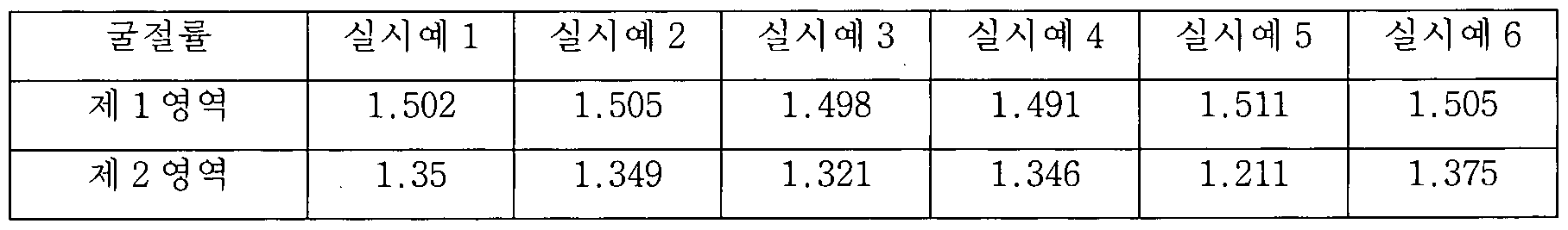 Table 3
상기 표 2 및 도 10 내지 15에서 확인되는 바와 같이, 실시예 1내지 6의 반사 방지 필름은 X선 조사에 의한 소각 산란에서 정의되는 산란 백터에 대한 산란 강도의 log값의 그래프에서 0.0758 내지 0. 1256 nm_1의 산란 백터에서 1개 이상의 피크를 나타내며, 또한 상기 표 2에 나타난 바와 같이 가시 광선 영역에서 0.70% 이하의 낮은 반사율을 나타내면서 높은 내스크래치성 및 방오성을 동시에 구현할 수 있다는 점이 확인되었다. 또한, 도 1내지 6에 나타난 바와 같이, 실시예 1내지 6의 반사 방지 필름의 저굴절층에서는 중공형 무기 나노 입자 및 솔리드형 무기 나노 입자가 상분리가 되어 있으며, 상기 솔리드형 무기 나노 입자가 상기 반사
방지 필름의 하드 코팅층 및 상기 저굴절층 간의 계면 쪽으로 대부분 존재하며 몰려 있으며, 상기 중공형 무기 나노 입자는 하드 코팅층으로부터 먼 쪽에 대부분 존재하며 몰려 있다는 점이 확인된다. As confirmed in Table 2 and FIGS. 10 to 15, the antireflection films of Examples 1 to 6 exhibited 0.0758 to 0 in a graph of log values of scattering intensity for scattering vectors defined in incineration scattering by X-ray irradiation. It was confirmed that at least one peak in a scattering vector of 1256 nm _1 and high scratch resistance and antifouling property can be simultaneously realized while exhibiting a low reflectance of 0.70% or less in the visible light region as shown in Table 2 above. 1 to 6, hollow inorganic nanoparticles and solid inorganic nanoparticles are phase-separated in the low refractive layer of the antireflection film of Examples 1 to 6, and the solid inorganic nanoparticles are reflect It is confirmed that most are present and clustered toward the interface between the hard coat layer and the low refractive layer of the prevention film, and the hollow inorganic nanoparticles are mostly present and crowded away from the hard coating layer.
또한, 상기 표 3에 나타난 바와 같이, 실시예의 저굴절층에서 중공형 무기 나노 입자 및 솔리드형 무기 나노 입자가 상분리되어 구분되는 제 1영격 및 제 2영역은 상이한 범위의 굴절율을 나타내며, 구체적으로 솔리드형 무기 나노 입자가 주로 분포하는 제 1영역은 1.420 이상의 굴절율을 나타내고 중공형 무기 나노 입자가 주로 분포하는 제 2영역은 1.400이하의 굴절율을 나타낸다는 점이 확인되었다. In addition, as shown in Table 3, in the low refractive layer of the embodiment, the first and second regions in which the hollow inorganic nanoparticles and the solid inorganic nanoparticles are separated from each other by phases exhibit different refractive indices. It was confirmed that the first region where the inorganic inorganic nanoparticles were mainly distributed showed a refractive index of 1.420 or more, and the second region where the hollow inorganic nanoparticles were mainly distributed showed a refractive index of 1.400 or less.
이에 반하여, 상기 표 2 및 도 16 내지 18에서 확인되는 바와 같이, 비교예 1 내지 3의 반사 방지 필름에 대한 X선 조사에 의한 소각 산란에서 정의되는 산란 백터에 대한 산란 강도의 log값의 그래프에서는 0.0758 내지 0. 1256 nm—1의 산란 백터 범위에서 피크가 나타나지 않으며, 이러한 비교예 1 내지 3의 반사 방지 필름은 각각 상대적으로 높은 반사율과 함께 낮은 내스크래치성 및 방오성을 나타낸다는 점이 확인되었다. On the other hand, as shown in Table 2 and FIGS. 16 to 18, in the graph of the log value of the scattering intensity for the scattering vector defined in the incineration scattering by X-ray irradiation for the antireflection films of Comparative Examples 1 to 3 0.0758 to 0.1256 peak does not appear in the scattering vector range nm- 1, these Comparative examples 1 to 3 of the anti-reflection film was confirmed that indicates the scratch resistance and antifouling low with a relatively high reflectance, respectively.
또한, 도 7 및 9에 나타난 바와 같이, 비교예 1 내지 3 의 반사 방지 필름의 저굴절층에서는 중공형 무기 나노 입자 및 솔리드형 무기 나노 입자가 상분리되지 않고 흔재되어 있는 점이 확인된다.
7 and 9, in the low refractive layer of the antireflection films of Comparative Examples 1 to 3, it is confirmed that the hollow inorganic nanoparticles and the solid inorganic nanoparticles are common without being phase separated.
Claims
【청구범위】 【Claims】
【청구항 11 【Claim 11
X선 조사에 의한 소각 산란에서 정의되는 산란 백터에 대한 산란 강도의 log값의 그래프에서, 0.0758 내지 0. 1256 ηηΓ1의 산란 백터 에서 1개 이상의 피크를 나타내는, 반사 방지 필름. An anti-reflective film showing one or more peaks at a scattering vector of 0.0758 to 0.1256 ηηΓ 1 in a graph of the log value of the scattering intensity with respect to the scattering vector defined in small-angle scattering by X-ray irradiation.
【청구항 2】 【Claim 2】
제 1항에 있어서, In clause 1,
상기 X선 조사에 의한 소각 산란은 lcm*lcm (가로 *세로)의 크기의 반사 방지 필름에 대하여 0.63 A 내지 1.54 A 의 파장의 X선을 ½의 거리에서 조사하여 측정하는, 반사 방지 필름. The small-angle scattering by X-ray irradiation is measured by irradiating X-rays with a wavelength of 0.63 A to 1.54 A at a distance of ½ to an anti-reflection film with a size of lcm * lcm (width * height). An anti-reflection film.
【청구항 3】 【Claim 3】
제 1항에 있어서, In clause 1,
상기 산란 백터는 하기 일반식 1로 정의되는, 반사 방지 필름: The scattering vector is an anti-reflection film defined by the following general formula 1:
[일반식 1] [General Formula 1]
q = 4π sin0 I λ 상기 일반식 1에서, q는 산란 백터이고, Θ는 산란 각도의 1/2값이며, λ는 조사된 X선의 파장이다. q = 4π sin0 I λ In General Formula 1, q is the scattering vector, Θ is half the scattering angle, and λ is the wavelength of the irradiated X-ray.
【청구항 4】 【Claim 4 】
제 1항에 있어서, According to clause 1,
상기 반사 반지 필름은 380nm 내지 780ran의 가시 광선 파장대 영역에서 0.7%이하의 평균 반사율을 나타내는, 반사 방지 필름. The reflective ring film is an anti-reflection film that exhibits an average reflectance of 0.7% or less in the visible light wavelength range of 380 nm to 780 ran.
【청구항 5】 【Claim 5】
제 1항에 있어서, In clause 1,
상기 반사 방지 필름은 하드 코팅충; 및 바인더 수지와 상기 바인더 수지에
분산된 중공형 무기 나노 입자 및 솔리드형 무기 나노 입자를 포함하는 저굴절층 ;을 포함하는, 반사 방지 필름 . The anti-reflection film is a hard coating; And the binder resin and the binder resin An anti-reflection film containing a low refractive index layer containing dispersed hollow inorganic nanoparticles and solid inorganic nanoparticles.
【청구항 6] [Claim 6]
계 5항에 있어서, In paragraph 5,
상기 하드 코팅층 및 상기 저굴절층 간의 계면 가까이에 솔리드형 무기 나노 입자가 중공형 무기 나노 입자 보다 많이 분포하는, 반사 방지 필름 An antireflection film in which solid inorganic nanoparticles are distributed more than hollow inorganic nanoparticles near the interface between the hard coating layer and the low refractive index layer.
【청구항 7】 【Claim 7】
제 6항에 있어서, In clause 6,
상기 하드 코팅층 및 상기 저굴절층 간의 계면으로부터 상기 저굴절층 전체 두께 50% 이내에 상기 솔리드형 무기 나노 입자 전체 중 70부피 ¾> 이상이 존재하는, 반사 방지 필름. An antireflection film in which more than 70% by volume of the total solid inorganic nanoparticles are present within 50% of the total thickness of the low refractive layer from the interface between the hard coating layer and the low refractive index layer.
【청구항 8】 【Claim 8】
거16항에 있어서, In paragraph 16,
상기 중공형 무기 나노 입자 전체 중 30부피 % 이상이 상기 솔리드형 무기 나노 입자 전체 보다 상기 하드 코팅층 및 상기 저굴절층 간의 계면으로부터 상기 저굴절층의 두께 방향으로 보다 먼 거리에 존재하는, 반사 방지 필름. An antireflection film in which more than 30% by volume of the total hollow inorganic nanoparticles exist at a greater distance in the thickness direction of the low refractive index layer from the interface between the hard coating layer and the low refractive index layer than all of the solid inorganic nanoparticles. .
【청구항 9] [Claim 9]
제 6항에 있어서, In clause 6,
상기 하드 코팅층과 상기 저굴절층의 계면으로부터 상기 저굴절층 전체 두께 30% 이내에 상기 솔리드형 무기 나노 입자 전체 중 70부피 % 이상이 존재하는, 반사 방지 필름. An antireflection film, wherein more than 70% by volume of the total solid inorganic nanoparticles exist within 30% of the total thickness of the low refractive layer from the interface between the hard coating layer and the low refractive index layer.
【청구항 10】 【Claim 10】
제 9항에 있어서,
상기 하드 코팅층과 상기 저굴절층의 계면으로부터 상기 저굴절층 전체 두께 30% 초과의 영역에 상기 중공형 무기 나노 입자 전체 중 70부피 이상이 존재하는, 반사 방지 필름. According to clause 9, An antireflection film, wherein more than 70 volumes of the total hollow inorganic nanoparticles exist in an area exceeding 30% of the total thickness of the low refractive index layer from the interface between the hard coating layer and the low refractive layer.
【청구항 11】 【Claim 11】
게 6항에 있어서, In paragraph 6,
상기 저굴절층은 상기 솔리드형 무기 나노 입자 전체 중 70부피 % 이상이 포함된 제 1층과 상기 중공형 무기 나노 입자 전체 중 70부피 % 이상이 포함된 게 2층을 포함하며, The low refractive index layer includes a first layer containing more than 70% by volume of the total solid inorganic nanoparticles and a second layer containing more than 70% by volume of the total hollow inorganic nanoparticles,
상기 제 1층이 제 2층에 비하여 상기 하드 코팅층 및 상기 저굴절층 간의 계면에 보다 가까이 위치하는, 반사 방지 필름. An antireflection film, wherein the first layer is located closer to the interface between the hard coating layer and the low refractive index layer than the second layer.
[청구항 12】 [Claim 12]
제 11항에 있어서, In clause 11,
상기 솔리드형 무기 나노 입자 전체 중 70부피 ¾> 이상이 포함된 거 U층은 상기 하드 코팅층 및 상기 저굴절층 간의 계면으로부터 상가 저굴절층 전체 두께 50% 이내에 위치하는, 반사 방지 필름. The U layer containing more than 70% by volume of the total solid inorganic nanoparticles is located within 50% of the total thickness of the commercial low refractive index layer from the interface between the hard coating layer and the low refractive index layer. An anti-reflection film.
【청구항 13】 【Claim 13】
게 5항에 있어서, In paragraph 5,
상기 솔리드형 무기 나노 입자가 상기 중공형 무기 나노 입자에 비하여 0.50 g/cin! 이상 높은 밀도를 갖는, 반사 방지 필름. The solid inorganic nanoparticles are 0.50 g/cin compared to the hollow inorganic nanoparticles ! An anti-reflective film with a higher density.
【청구항 14] [Claim 14]
제 5항에 있어서, According to clause 5,
상기 솔리드형 무기 나노 입자 및 상기 중공형 무기 나노 입자 각각은 표면에 (메트)아크릴레이트기, 에폭사이드기, 비닐기 (Vinyl ) 및 싸이올기 (Thiol )로 이루어진 군에서 선택된 1종 이상의 반웅성 작용기를 함유하는, 반사 방지 필름.
Each of the solid inorganic nanoparticles and the hollow inorganic nanoparticles has one or more semi-male functional groups selected from the group consisting of a (meth)acrylate group, an epoxide group, a vinyl group, and a thiol group on the surface. Containing, anti-reflective film.
【청구항 15] [Claim 15]
제 5항에 있어서, In clause 5,
상기 저굴절층에 포함되는 바인더 수지는 광중합성 화합물의 (공)중합체 및 광반웅성 작용기를 포함한 함블소 화합물 간의 가교 (공)중합체를 포함하는, 반사 방지 필름. The binder resin included in the low refractive index layer is an anti-reflection film comprising a (co)polymer of a photopolymerizable compound and a crosslinking (co)polymer between a Hambleso compound containing a photoreactive functional group.
【청구항 16】 【Claim 16】
제 5항에 있어서, In clause 5,
상기 저굴절층은 상기 광중합성 화합물의 (공)중합체 100중량부 대비 상기 중공형 무기 나노 입자 10 내지 400 증량부 및 상기 솔리드형 무기 나노 입자 10 내지 400중량부를 포함하는, 반사 방지 필름. The low refractive index layer includes 10 to 400 parts by weight of the hollow inorganic nanoparticles and 10 to 400 parts by weight of the solid inorganic nanoparticles relative to 100 parts by weight of the (co)polymer of the photopolymerizable compound.
【청구항 17】 【Claim 17】
제 15항에 있어서, In clause 15,
상기 광반웅성 작용기를 포함한 함블소 화합물은 각각 2 , 000 내지 200, 000의 중량평균분자량을 갖는, 반사 방지 필름. The Hambleso compound containing the photoreactive male functional group is an anti-reflective film having a weight average molecular weight of 2,000 to 200,000, respectively.
【청구항 18] [Claim 18]
제 15항에 있어서, In clause 15,
상기 바인더 수지는 상기 광중합성 화합물의 (공)중합체 100중량부에 대하여 상기 광반웅성 작용기를 포함한 함불소 화합물을 20 내지 300중량부로 포함하는, 반사 방지 필름. 【청구항 19】 The binder resin is an antireflection film comprising 20 to 300 parts by weight of a fluorinated compound containing the photoreactive functional group based on 100 parts by weight of the (co)polymer of the photopolymerizable compound. 【Claim 19】
제 5항에 있어서, In clause 5,
상기 하드 코팅층은 광경화성 수지를 포함하는 바인더 수지 및 상기 바인더 수지에 분산된 유기 또는 무기 미립자;를 포함하는, 반사 방지 필름. 【청구항 20】
제 19항에 있어서, The hard coating layer is an anti-reflection film comprising a binder resin containing a photocurable resin and organic or inorganic fine particles dispersed in the binder resin. 【Claim 20】 In clause 19,
상기 유기 미립자는 1 내지 10 의 입경을 가지며, The organic fine particles have a particle size of 1 to 10,
상기 무기 입자는 1 nra 내지 500 nm의 입경을 갖는, 반사 방지 필름.
The inorganic particles have a particle size of 1 nra to 500 nm, an anti-reflection film.
Priority Applications (7)
| Application Number | Priority Date | Filing Date | Title |
|---|---|---|---|
| CN202010379588.1A CN111580192B (en) | 2016-03-09 | 2017-03-09 | Antireflection film |
| EP17763598.4A EP3318903A4 (en) | 2016-03-09 | 2017-03-09 | Anti-reflective film |
| JP2018518713A JP6476347B2 (en) | 2016-03-09 | 2017-03-09 | Antireflection film |
| CN201780003073.8A CN108027452B (en) | 2016-03-09 | 2017-03-09 | Antireflection film |
| US15/750,330 US10627547B2 (en) | 2016-03-09 | 2017-03-09 | Anti-reflective film |
| US16/815,227 US11262481B2 (en) | 2016-03-09 | 2020-03-11 | Anti-reflective film |
| US16/815,256 US11275199B2 (en) | 2016-03-09 | 2020-03-11 | Anti-reflective film |
Applications Claiming Priority (8)
| Application Number | Priority Date | Filing Date | Title |
|---|---|---|---|
| KR20160028468 | 2016-03-09 | ||
| KR10-2016-0028468 | 2016-03-09 | ||
| KR20160029336 | 2016-03-11 | ||
| KR10-2016-0029336 | 2016-03-11 | ||
| KR10-2016-0030395 | 2016-03-14 | ||
| KR20160030395 | 2016-03-14 | ||
| KR10-2017-0029959 | 2017-03-09 | ||
| KR1020170029959A KR101906492B1 (en) | 2016-03-14 | 2017-03-09 | Anti-reflective film |
Related Child Applications (3)
| Application Number | Title | Priority Date | Filing Date |
|---|---|---|---|
| US15/750,330 A-371-Of-International US10627547B2 (en) | 2016-03-09 | 2017-03-09 | Anti-reflective film |
| US16/815,227 Continuation US11262481B2 (en) | 2016-03-09 | 2020-03-11 | Anti-reflective film |
| US16/815,256 Continuation US11275199B2 (en) | 2016-03-09 | 2020-03-11 | Anti-reflective film |
Publications (1)
| Publication Number | Publication Date |
|---|---|
| WO2017155338A1 true WO2017155338A1 (en) | 2017-09-14 |
Family
ID=59790638
Family Applications (1)
| Application Number | Title | Priority Date | Filing Date |
|---|---|---|---|
| PCT/KR2017/002583 WO2017155338A1 (en) | 2016-03-09 | 2017-03-09 | Anti-reflective film |
Country Status (1)
| Country | Link |
|---|---|
| WO (1) | WO2017155338A1 (en) |
Cited By (4)
| Publication number | Priority date | Publication date | Assignee | Title |
|---|---|---|---|---|
| JP2020532765A (en) * | 2018-06-26 | 2020-11-12 | エルジー・ケム・リミテッド | Anti-reflection film, polarizing plate and display device |
| JP2020535462A (en) * | 2018-01-24 | 2020-12-03 | エルジー・ケム・リミテッド | Anti-reflective film, polarizing plate and display device |
| US20220155507A1 (en) * | 2019-03-29 | 2022-05-19 | Lg Chem, Ltd. | Reddening-resistant layer |
| US11428848B2 (en) | 2018-01-24 | 2022-08-30 | Lg Chem, Ltd. | Anti-reflective film, polarizing plate, and display apparatus |
Citations (5)
| Publication number | Priority date | Publication date | Assignee | Title |
|---|---|---|---|---|
| KR20090046873A (en) * | 2006-08-04 | 2009-05-11 | 이 아이 듀폰 디 네모아 앤드 캄파니 | Low refractive index composition |
| JP2009217258A (en) * | 2008-02-13 | 2009-09-24 | Fujifilm Corp | Optical film, method for producing the same, polarizing plate, and image display device |
| WO2009120983A2 (en) * | 2008-03-27 | 2009-10-01 | Rensselaer Polytechnic Institute | Ultra-low reflectance broadband omni-directional anti-reflection coating |
| KR20100039869A (en) * | 2007-08-01 | 2010-04-16 | 다이니폰 인사츠 가부시키가이샤 | Antireflection laminate |
| KR20120093212A (en) * | 2009-10-16 | 2012-08-22 | 다이니폰 인사츠 가부시키가이샤 | Optical film and display panel |
-
2017
- 2017-03-09 WO PCT/KR2017/002583 patent/WO2017155338A1/en active Application Filing
Patent Citations (5)
| Publication number | Priority date | Publication date | Assignee | Title |
|---|---|---|---|---|
| KR20090046873A (en) * | 2006-08-04 | 2009-05-11 | 이 아이 듀폰 디 네모아 앤드 캄파니 | Low refractive index composition |
| KR20100039869A (en) * | 2007-08-01 | 2010-04-16 | 다이니폰 인사츠 가부시키가이샤 | Antireflection laminate |
| JP2009217258A (en) * | 2008-02-13 | 2009-09-24 | Fujifilm Corp | Optical film, method for producing the same, polarizing plate, and image display device |
| WO2009120983A2 (en) * | 2008-03-27 | 2009-10-01 | Rensselaer Polytechnic Institute | Ultra-low reflectance broadband omni-directional anti-reflection coating |
| KR20120093212A (en) * | 2009-10-16 | 2012-08-22 | 다이니폰 인사츠 가부시키가이샤 | Optical film and display panel |
Non-Patent Citations (1)
| Title |
|---|
| See also references of EP3318903A4 * |
Cited By (8)
| Publication number | Priority date | Publication date | Assignee | Title |
|---|---|---|---|---|
| JP2020535462A (en) * | 2018-01-24 | 2020-12-03 | エルジー・ケム・リミテッド | Anti-reflective film, polarizing plate and display device |
| US11428848B2 (en) | 2018-01-24 | 2022-08-30 | Lg Chem, Ltd. | Anti-reflective film, polarizing plate, and display apparatus |
| US11506820B2 (en) | 2018-01-24 | 2022-11-22 | Lg Chem, Ltd. | Anti-reflective film, polarizing plate, and display apparatus |
| JP2020532765A (en) * | 2018-06-26 | 2020-11-12 | エルジー・ケム・リミテッド | Anti-reflection film, polarizing plate and display device |
| US11624857B2 (en) | 2018-06-26 | 2023-04-11 | Lg Chem, Ltd. | Anti-reflective film, polarizing plate, and display apparatus |
| US20220155507A1 (en) * | 2019-03-29 | 2022-05-19 | Lg Chem, Ltd. | Reddening-resistant layer |
| JP2022527897A (en) * | 2019-03-29 | 2022-06-07 | エルジー・ケム・リミテッド | Red-resistant layer |
| JP7399536B2 (en) | 2019-03-29 | 2023-12-18 | エルジー・ケム・リミテッド | redness resistant layer |
Similar Documents
| Publication | Publication Date | Title |
|---|---|---|
| JP7411536B2 (en) | anti-reflection film | |
| KR101973196B1 (en) | Anti-reflective film | |
| KR101953776B1 (en) | Anti-refractive film | |
| KR101973197B1 (en) | Anti-reflective film | |
| WO2018012802A1 (en) | Anti-reflection film | |
| KR102040223B1 (en) | Anti-reflective film | |
| JP6690808B2 (en) | Antireflection film and manufacturing method thereof | |
| WO2018199487A1 (en) | Antireflective film | |
| KR101977934B1 (en) | Anti-reflective film | |
| WO2017155338A1 (en) | Anti-reflective film | |
| EP3413101B1 (en) | Anti-reflection film | |
| KR101977933B1 (en) | Anti-reflective film and preparation method of the same | |
| WO2017155335A1 (en) | Anti-reflective film | |
| KR101907653B1 (en) | Anti-reflective film | |
| WO2017155337A1 (en) | Anti-reflection film | |
| KR20200020768A (en) | Anti-reflective film and preparation method of the same | |
| WO2017155358A1 (en) | Anti-reflective film and method for producing same |
Legal Events
| Date | Code | Title | Description |
|---|---|---|---|
| WWE | Wipo information: entry into national phase |
Ref document number: 2017763598 Country of ref document: EP |
|
| WWE | Wipo information: entry into national phase |
Ref document number: 15750330 Country of ref document: US |
|
| WWE | Wipo information: entry into national phase |
Ref document number: 2018518713 Country of ref document: JP |
|
| NENP | Non-entry into the national phase |
Ref country code: DE |