WO2017154721A1 - Liquid discharge treatment device and liquid discharge treatment method - Google Patents
Liquid discharge treatment device and liquid discharge treatment method Download PDFInfo
- Publication number
- WO2017154721A1 WO2017154721A1 PCT/JP2017/008252 JP2017008252W WO2017154721A1 WO 2017154721 A1 WO2017154721 A1 WO 2017154721A1 JP 2017008252 W JP2017008252 W JP 2017008252W WO 2017154721 A1 WO2017154721 A1 WO 2017154721A1
- Authority
- WO
- WIPO (PCT)
- Prior art keywords
- permanent magnet
- drainage
- unit
- pipe
- transport unit
- Prior art date
Links
Images


Classifications
-
- B—PERFORMING OPERATIONS; TRANSPORTING
- B03—SEPARATION OF SOLID MATERIALS USING LIQUIDS OR USING PNEUMATIC TABLES OR JIGS; MAGNETIC OR ELECTROSTATIC SEPARATION OF SOLID MATERIALS FROM SOLID MATERIALS OR FLUIDS; SEPARATION BY HIGH-VOLTAGE ELECTRIC FIELDS
- B03C—MAGNETIC OR ELECTROSTATIC SEPARATION OF SOLID MATERIALS FROM SOLID MATERIALS OR FLUIDS; SEPARATION BY HIGH-VOLTAGE ELECTRIC FIELDS
- B03C1/00—Magnetic separation
- B03C1/02—Magnetic separation acting directly on the substance being separated
- B03C1/10—Magnetic separation acting directly on the substance being separated with cylindrical material carriers
- B03C1/12—Magnetic separation acting directly on the substance being separated with cylindrical material carriers with magnets moving during operation; with movable pole pieces
-
- B—PERFORMING OPERATIONS; TRANSPORTING
- B03—SEPARATION OF SOLID MATERIALS USING LIQUIDS OR USING PNEUMATIC TABLES OR JIGS; MAGNETIC OR ELECTROSTATIC SEPARATION OF SOLID MATERIALS FROM SOLID MATERIALS OR FLUIDS; SEPARATION BY HIGH-VOLTAGE ELECTRIC FIELDS
- B03C—MAGNETIC OR ELECTROSTATIC SEPARATION OF SOLID MATERIALS FROM SOLID MATERIALS OR FLUIDS; SEPARATION BY HIGH-VOLTAGE ELECTRIC FIELDS
- B03C1/00—Magnetic separation
- B03C1/02—Magnetic separation acting directly on the substance being separated
- B03C1/025—High gradient magnetic separators
- B03C1/027—High gradient magnetic separators with reciprocating canisters
-
- B—PERFORMING OPERATIONS; TRANSPORTING
- B03—SEPARATION OF SOLID MATERIALS USING LIQUIDS OR USING PNEUMATIC TABLES OR JIGS; MAGNETIC OR ELECTROSTATIC SEPARATION OF SOLID MATERIALS FROM SOLID MATERIALS OR FLUIDS; SEPARATION BY HIGH-VOLTAGE ELECTRIC FIELDS
- B03C—MAGNETIC OR ELECTROSTATIC SEPARATION OF SOLID MATERIALS FROM SOLID MATERIALS OR FLUIDS; SEPARATION BY HIGH-VOLTAGE ELECTRIC FIELDS
- B03C1/00—Magnetic separation
- B03C1/02—Magnetic separation acting directly on the substance being separated
- B03C1/025—High gradient magnetic separators
- B03C1/031—Component parts; Auxiliary operations
- B03C1/032—Matrix cleaning systems
-
- B—PERFORMING OPERATIONS; TRANSPORTING
- B03—SEPARATION OF SOLID MATERIALS USING LIQUIDS OR USING PNEUMATIC TABLES OR JIGS; MAGNETIC OR ELECTROSTATIC SEPARATION OF SOLID MATERIALS FROM SOLID MATERIALS OR FLUIDS; SEPARATION BY HIGH-VOLTAGE ELECTRIC FIELDS
- B03C—MAGNETIC OR ELECTROSTATIC SEPARATION OF SOLID MATERIALS FROM SOLID MATERIALS OR FLUIDS; SEPARATION BY HIGH-VOLTAGE ELECTRIC FIELDS
- B03C1/00—Magnetic separation
- B03C1/02—Magnetic separation acting directly on the substance being separated
- B03C1/025—High gradient magnetic separators
- B03C1/031—Component parts; Auxiliary operations
- B03C1/033—Component parts; Auxiliary operations characterised by the magnetic circuit
- B03C1/0332—Component parts; Auxiliary operations characterised by the magnetic circuit using permanent magnets
-
- B—PERFORMING OPERATIONS; TRANSPORTING
- B03—SEPARATION OF SOLID MATERIALS USING LIQUIDS OR USING PNEUMATIC TABLES OR JIGS; MAGNETIC OR ELECTROSTATIC SEPARATION OF SOLID MATERIALS FROM SOLID MATERIALS OR FLUIDS; SEPARATION BY HIGH-VOLTAGE ELECTRIC FIELDS
- B03C—MAGNETIC OR ELECTROSTATIC SEPARATION OF SOLID MATERIALS FROM SOLID MATERIALS OR FLUIDS; SEPARATION BY HIGH-VOLTAGE ELECTRIC FIELDS
- B03C1/00—Magnetic separation
- B03C1/02—Magnetic separation acting directly on the substance being separated
- B03C1/035—Open gradient magnetic separators, i.e. separators in which the gap is unobstructed, characterised by the configuration of the gap
-
- B—PERFORMING OPERATIONS; TRANSPORTING
- B03—SEPARATION OF SOLID MATERIALS USING LIQUIDS OR USING PNEUMATIC TABLES OR JIGS; MAGNETIC OR ELECTROSTATIC SEPARATION OF SOLID MATERIALS FROM SOLID MATERIALS OR FLUIDS; SEPARATION BY HIGH-VOLTAGE ELECTRIC FIELDS
- B03C—MAGNETIC OR ELECTROSTATIC SEPARATION OF SOLID MATERIALS FROM SOLID MATERIALS OR FLUIDS; SEPARATION BY HIGH-VOLTAGE ELECTRIC FIELDS
- B03C1/00—Magnetic separation
- B03C1/02—Magnetic separation acting directly on the substance being separated
- B03C1/10—Magnetic separation acting directly on the substance being separated with cylindrical material carriers
- B03C1/14—Magnetic separation acting directly on the substance being separated with cylindrical material carriers with non-movable magnets
-
- B—PERFORMING OPERATIONS; TRANSPORTING
- B03—SEPARATION OF SOLID MATERIALS USING LIQUIDS OR USING PNEUMATIC TABLES OR JIGS; MAGNETIC OR ELECTROSTATIC SEPARATION OF SOLID MATERIALS FROM SOLID MATERIALS OR FLUIDS; SEPARATION BY HIGH-VOLTAGE ELECTRIC FIELDS
- B03C—MAGNETIC OR ELECTROSTATIC SEPARATION OF SOLID MATERIALS FROM SOLID MATERIALS OR FLUIDS; SEPARATION BY HIGH-VOLTAGE ELECTRIC FIELDS
- B03C1/00—Magnetic separation
- B03C1/02—Magnetic separation acting directly on the substance being separated
- B03C1/28—Magnetic plugs and dipsticks
- B03C1/284—Magnetic plugs and dipsticks with associated cleaning means, e.g. retractable non-magnetic sleeve
-
- B—PERFORMING OPERATIONS; TRANSPORTING
- B03—SEPARATION OF SOLID MATERIALS USING LIQUIDS OR USING PNEUMATIC TABLES OR JIGS; MAGNETIC OR ELECTROSTATIC SEPARATION OF SOLID MATERIALS FROM SOLID MATERIALS OR FLUIDS; SEPARATION BY HIGH-VOLTAGE ELECTRIC FIELDS
- B03C—MAGNETIC OR ELECTROSTATIC SEPARATION OF SOLID MATERIALS FROM SOLID MATERIALS OR FLUIDS; SEPARATION BY HIGH-VOLTAGE ELECTRIC FIELDS
- B03C1/00—Magnetic separation
- B03C1/02—Magnetic separation acting directly on the substance being separated
- B03C1/28—Magnetic plugs and dipsticks
- B03C1/286—Magnetic plugs and dipsticks disposed at the inner circumference of a recipient, e.g. magnetic drain bolt
-
- B—PERFORMING OPERATIONS; TRANSPORTING
- B03—SEPARATION OF SOLID MATERIALS USING LIQUIDS OR USING PNEUMATIC TABLES OR JIGS; MAGNETIC OR ELECTROSTATIC SEPARATION OF SOLID MATERIALS FROM SOLID MATERIALS OR FLUIDS; SEPARATION BY HIGH-VOLTAGE ELECTRIC FIELDS
- B03C—MAGNETIC OR ELECTROSTATIC SEPARATION OF SOLID MATERIALS FROM SOLID MATERIALS OR FLUIDS; SEPARATION BY HIGH-VOLTAGE ELECTRIC FIELDS
- B03C1/00—Magnetic separation
- B03C1/02—Magnetic separation acting directly on the substance being separated
- B03C1/28—Magnetic plugs and dipsticks
- B03C1/288—Magnetic plugs and dipsticks disposed at the outer circumference of a recipient
-
- B—PERFORMING OPERATIONS; TRANSPORTING
- B03—SEPARATION OF SOLID MATERIALS USING LIQUIDS OR USING PNEUMATIC TABLES OR JIGS; MAGNETIC OR ELECTROSTATIC SEPARATION OF SOLID MATERIALS FROM SOLID MATERIALS OR FLUIDS; SEPARATION BY HIGH-VOLTAGE ELECTRIC FIELDS
- B03C—MAGNETIC OR ELECTROSTATIC SEPARATION OF SOLID MATERIALS FROM SOLID MATERIALS OR FLUIDS; SEPARATION BY HIGH-VOLTAGE ELECTRIC FIELDS
- B03C1/00—Magnetic separation
- B03C1/02—Magnetic separation acting directly on the substance being separated
- B03C1/30—Combinations with other devices, not otherwise provided for
-
- C—CHEMISTRY; METALLURGY
- C02—TREATMENT OF WATER, WASTE WATER, SEWAGE, OR SLUDGE
- C02F—TREATMENT OF WATER, WASTE WATER, SEWAGE, OR SLUDGE
- C02F1/00—Treatment of water, waste water, or sewage
-
- C—CHEMISTRY; METALLURGY
- C02—TREATMENT OF WATER, WASTE WATER, SEWAGE, OR SLUDGE
- C02F—TREATMENT OF WATER, WASTE WATER, SEWAGE, OR SLUDGE
- C02F1/00—Treatment of water, waste water, or sewage
- C02F1/52—Treatment of water, waste water, or sewage by flocculation or precipitation of suspended impurities
-
- B—PERFORMING OPERATIONS; TRANSPORTING
- B03—SEPARATION OF SOLID MATERIALS USING LIQUIDS OR USING PNEUMATIC TABLES OR JIGS; MAGNETIC OR ELECTROSTATIC SEPARATION OF SOLID MATERIALS FROM SOLID MATERIALS OR FLUIDS; SEPARATION BY HIGH-VOLTAGE ELECTRIC FIELDS
- B03C—MAGNETIC OR ELECTROSTATIC SEPARATION OF SOLID MATERIALS FROM SOLID MATERIALS OR FLUIDS; SEPARATION BY HIGH-VOLTAGE ELECTRIC FIELDS
- B03C2201/00—Details of magnetic or electrostatic separation
- B03C2201/18—Magnetic separation whereby the particles are suspended in a liquid
-
- B—PERFORMING OPERATIONS; TRANSPORTING
- B03—SEPARATION OF SOLID MATERIALS USING LIQUIDS OR USING PNEUMATIC TABLES OR JIGS; MAGNETIC OR ELECTROSTATIC SEPARATION OF SOLID MATERIALS FROM SOLID MATERIALS OR FLUIDS; SEPARATION BY HIGH-VOLTAGE ELECTRIC FIELDS
- B03C—MAGNETIC OR ELECTROSTATIC SEPARATION OF SOLID MATERIALS FROM SOLID MATERIALS OR FLUIDS; SEPARATION BY HIGH-VOLTAGE ELECTRIC FIELDS
- B03C2201/00—Details of magnetic or electrostatic separation
- B03C2201/24—Details of magnetic or electrostatic separation for measuring or calculating parameters, efficiency, etc.
-
- B—PERFORMING OPERATIONS; TRANSPORTING
- B03—SEPARATION OF SOLID MATERIALS USING LIQUIDS OR USING PNEUMATIC TABLES OR JIGS; MAGNETIC OR ELECTROSTATIC SEPARATION OF SOLID MATERIALS FROM SOLID MATERIALS OR FLUIDS; SEPARATION BY HIGH-VOLTAGE ELECTRIC FIELDS
- B03C—MAGNETIC OR ELECTROSTATIC SEPARATION OF SOLID MATERIALS FROM SOLID MATERIALS OR FLUIDS; SEPARATION BY HIGH-VOLTAGE ELECTRIC FIELDS
- B03C2201/00—Details of magnetic or electrostatic separation
- B03C2201/28—Parts being easily removable for cleaning purposes
-
- B—PERFORMING OPERATIONS; TRANSPORTING
- B03—SEPARATION OF SOLID MATERIALS USING LIQUIDS OR USING PNEUMATIC TABLES OR JIGS; MAGNETIC OR ELECTROSTATIC SEPARATION OF SOLID MATERIALS FROM SOLID MATERIALS OR FLUIDS; SEPARATION BY HIGH-VOLTAGE ELECTRIC FIELDS
- B03C—MAGNETIC OR ELECTROSTATIC SEPARATION OF SOLID MATERIALS FROM SOLID MATERIALS OR FLUIDS; SEPARATION BY HIGH-VOLTAGE ELECTRIC FIELDS
- B03C2201/00—Details of magnetic or electrostatic separation
- B03C2201/30—Details of magnetic or electrostatic separation for use in or with vehicles
Definitions
- the present invention relates to a drainage treatment apparatus and a drainage treatment method.
- the present invention provides a drainage treatment apparatus for treating drainage discharged from a scrubber device.
- the drainage treatment apparatus may include a magnetic powder addition unit that adds magnetic powder to the drainage.
- the drainage treatment apparatus may include a transport unit that transports the drainage.
- the drainage treatment apparatus may be provided with an adsorption unit which is provided in the transport unit and adsorbs a combined substance containing at least a target substance to be treated and magnetic powder contained in the drainage and held in the transport unit.
- the adsorption unit may be capable of re-releasing the adsorbed bound substance into the transport unit.
- the adsorption unit may have a permanent magnet provided so as to be directly insertable into and removable from the transport unit.
- the permanent magnet may adsorb the bound substance by being inserted into the transport section, and may release the bound substance into the transport section by being removed from the inside of the transport section.
- the adsorption part may have a permanent magnet.
- the tube wall of the transport may have a recess into which the permanent magnet can be inserted and removed.
- the permanent magnet may be inserted into the recess so that the combination is adsorbed on the inner wall of the recess and the permanent magnet is removed from the recess so that the combination is re-emitted into the transport section.
- the permanent magnet may be in the form of a rod having a longitudinal.
- the permanent magnet may be inserted such that the longitudinal direction is orthogonal to the stretching direction of the transport unit.
- the adsorption unit is provided at a position different from the first permanent magnet in the extending direction of the first permanent magnet and the transport unit, and is provided on a tube wall opposite to the first permanent magnet. And a permanent magnet.
- the adsorption unit may have a first permanent magnet provided to be directly insertable into and removable from the transport unit.
- the adsorption unit may have a second permanent magnet provided upstream of the first permanent magnet in the transport unit.
- the tube wall of the transport may have a recess into which the second permanent magnet can be inserted and removed.
- the adsorption part may have a plurality of permanent magnets.
- the density of the permanent magnet upstream of the transport may be lower than the density of the permanent magnet downstream of the transport.
- the permanent magnet may be in the form of a rod having a longitudinal.
- the permanent magnet may be inserted such that the longitudinal direction is parallel to the extending direction of the transport unit.
- the transport unit may have a large diameter portion with a larger diameter than the upstream and downstream pipes.
- the large diameter portion may have side surfaces on which the openings of the upstream and downstream pipes are formed.
- the permanent magnet may be provided on the side of the large diameter portion.
- the drainage treatment apparatus may further include a measurement unit that measures the concentration of the bound substance contained in the drainage that can flow in the transport unit downstream of the adsorption unit.
- the measuring unit may measure the flow rate of the drainage.
- the drainage treatment apparatus may further include a control unit that controls the amount of permanent magnet inserted into the transport unit or the recess based on the measurement result in the measurement unit.
- control unit may re-release the conjugate to the adsorption unit so that the concentration of the conjugate measured by the measurement unit is maintained within the allowable range.
- the control unit may re-emit the binder sequentially from the downstream adsorption unit when the binder is re-released to the adsorption unit.
- the inner wall of the transport unit may be provided with a projection that scrapes off a substance adsorbed on the surface of the permanent magnet as the permanent magnet is removed from the transport unit.
- the inner wall of the transfer unit may be provided with a valve that closes the opening in which the permanent magnet was inserted as the permanent magnet is removed from the transfer unit.
- a drainage treatment method for treating drainage discharged from a scrubber device wherein a magnetic powder addition step of adding magnetic powder to the drainage, and drainage of the waste liquid to which the magnetic powder is added
- a drainage treatment method comprising: a conveying step of conveying by a part; and an adsorbing step of adsorbing a combined substance of a target substance to be treated and magnetic powder contained in the drainage by an adsorbing unit provided in the conveying unit I will provide a.
- FIG. 1 shows a drainage treatment apparatus 100 according to one embodiment of the present invention, together with an exhaust gas source 110 and a scrubber apparatus 120.
- 5 is a cross-sectional view showing an example of a suction unit 40.
- FIG. FIG. 7 is a cross-sectional view showing a permanent magnet 42 in the process of being pulled out of the inside of the pipe 20.
- FIG. 7 is a cross-sectional view showing another example of the adsorbing unit 40 and the pipe 20.
- FIG. 7 is a cross-sectional view showing a permanent magnet 42 in the process of being pulled out of the inside of the pipe 20. It is a figure which shows the example of arrangement
- FIG. 6 is a view showing a configuration example of a pipe 20.
- 5 is a cross-sectional view showing a structural example of a pipe 20.
- FIG. 8 is a cross-sectional view showing another structural example of the pipe 20.
- FIG. 8 is a cross-sectional view showing another structural example of the pipe 20.
- FIG. 5 is a flowchart showing an outline of the operation of the drainage processing apparatus 100.
- FIG. 1 is a view showing a drainage treatment apparatus 100 according to an embodiment of the present invention, together with an exhaust gas source 110 and a scrubber apparatus 120.
- the exhaust gas source 110 is an engine or the like provided on a ship.
- the exhaust gas emitted by the exhaust gas source 110 contains suspended substances such as black carbon.
- the scrubber device 120 is installed on a ship or the like to treat the exhaust gas emitted by the exhaust gas source 110.
- the scrubber apparatus 120 takes in suspended substances in the exhaust gas into the liquid by spraying a liquid such as seawater in a tower through which the exhaust gas passes.
- the scrubber device 120 discharges the drainage that has taken in the suspended matter to the drainage processing device 100.
- the drainage treatment apparatus 100 includes a conveyance unit 10, a magnetic powder addition unit 62, a pH adjustment unit 64, a coagulant addition unit 66, a control unit 70, and a measurement unit 80.
- the transport unit 10 transports the drainage of the scrubber device 120.
- the transport unit 10 may subject the drainage to a predetermined treatment and recycle the drainage to the scrubber device 120 in order to reuse the drainage in the scrubber device 120, and drain the drainage subjected to the predetermined treatment to the outside of a ship or the like. You may
- the transport unit 10 in this example includes a pipe 20, a tank 60, a pump 68, and a suction unit 40.
- the tank 60 is connected to the scrubber device 120 by a pipe 20.
- the tank 60 holds the drainage of the scrubber device 120 and performs predetermined processing.
- the magnetic powder addition unit 62 adds the magnetic powder to the drainage of the scrubber device 120.
- the magnetic powder addition unit 62 of the present embodiment charges the magnetic powder into the tank 60.
- the magnetic powder addition unit 62 may directly charge the magnetic powder into the tank 60 or may charge a liquid containing the magnetic powder into the tank 60.
- the tank 60 is preferably provided with a stirring function. As a result, at least a part of the target substance to be treated in the drainage is bound to the magnetic powder.
- the magnetic powder is formed of a material capable of binding to the substance to be treated such as black carbon.
- the magnetic powder may be either paramagnetic or ferromagnetic.
- the magnetic powder is iron oxide such as triiron tetraoxide, cobalt, chromium oxide, ferrite, or a mixture thereof.
- the particle size of the magnetic substance may be 0.05 ⁇ m or more and 10 ⁇ m or less, and may be 0.05 ⁇ m or more and 5 ⁇ m or less.
- the coercive force of the magnetic powder may be 10 4 / 4 ⁇ A / m or more and 4 ⁇ 10 5 / 4 ⁇ A / m or less, and 2 ⁇ 10 5 / 4 ⁇ A / m or more and 3 ⁇ 10 5 / 4 ⁇ A / m or less May be
- the addition amount of the magnetic powder may be 0.1 or more and 10 or less, or may be 0.5 or more and 5 or less in mass ratio with respect to the substance to be treated.
- the amount of the magnetic powder added is smaller than the above-mentioned range, the efficiency of forming a combination containing the substance to be treated and the magnetic powder is deteriorated.
- An example of the combination is a magnetic floc in which the substance to be treated and the magnetic powder are aggregated by the aggregating agent, but the combination is not limited to one including the aggregating agent.
- the combined substance may contain at least the substance to be treated and the magnetic powder.
- the addition amount of the magnetic powder is larger than the above-mentioned range, the magnetic powder is excessively added, and the magnetic powder to be wasted increases.
- the control unit 70 may control the amount of the magnetic powder charged into the tank 60 by the magnetic powder addition unit 62 in accordance with the concentration of the process target substance contained in the drainage of the scrubber device 120.
- concentration of the substance to be treated can be estimated from the turbidity of the drainage of the scrubber device 120 or the concentration of suspended solids (SS: Suspended Solids) (hereinafter referred to as “suspended solids concentration”).
- the measuring unit 80 may measure the turbidity or suspended substance concentration of the drainage of the scrubber device 120. For example, the turbidity of the effluent can be measured by a method according to JIS K 0101 9.3.
- the suspended matter concentration of the drainage can be measured by a method in accordance with JIS K 0102 14.1 or the like.
- the control unit 70 may store in advance information indicating the relationship between the turbidity of the drainage and / or the suspended substance concentration and the amount of magnetic powder to be charged.
- the coagulant addition unit 66 adds the coagulant to the drainage of the scrubber device 120.
- the coagulant addition part 66 of the present example supplies the coagulant to the tank 60.
- magnetic flock containing the magnetic powder and the substance to be treated is formed. This can promote the formation of a combination of the magnetic powder and the substance to be treated.
- the material of the flocculant is, by way of example, polyaluminum chloride, polyferric sulfate, aluminum sulfate, polymeric materials or mixtures thereof.
- the polymeric material is, for example, nonionic, cationic, anionic or amphoteric.
- the addition amount of the aggregating agent may be 0.005 or more and 1 or less, or may be 0.01 or more and 0.5 or less per 1 mass part of the substance to be treated.
- the addition amount of the coagulant is smaller than the above-mentioned range, the efficiency of forming the magnetic floc deteriorates.
- the addition amount of the coagulant is larger than the above-described range, the coagulant is excessively added, and the amount of the coagulant to be wasted increases.
- the control unit 70 may control the amount of the coagulant added to the tank 60 by the coagulant addition unit 66 in accordance with the concentration of the substance to be treated contained in the drainage discharged per unit time from the scrubber device 120 .
- the measuring unit 80 may measure the turbidity or suspended substance concentration of the drainage of the scrubber device 120. As a measuring method, the method according to 9.3 of said JIS K 0101, the method according to 14.1 of JIS K 0102, etc. can be used.
- the control unit 70 may store in advance information indicating the relationship between the turbidity of the drainage and / or the suspended substance concentration and the amount of flocculant to be charged.
- the pH adjusting unit 64 adjusts the pH of the drainage of the scrubber device 120.
- the pH adjusting unit 64 of the present embodiment charges the tank 60 with the pH adjusting agent.
- the pH adjusting unit 64 may adjust the pH of the drainage so that the pH of the drainage becomes 4 or more and 11 or less. By adjusting the pH of the drainage, the alkali consumed by the flocculant can be compensated.
- the drainage liquid to which the magnetic powder is added in the tank 60 is conveyed to the adsorption unit 40 through the pipe 20.
- a pump 68 for suctioning drainage from the tank 60 may be provided between the tank 60 and the adsorption unit 40.
- the suction unit 40 is provided in the transport unit 10.
- the adsorption unit 40 adsorbs a combination of the target substance to be treated and the magnetic powder contained in the drainage.
- the adsorption unit 40 generates a magnetic field to adsorb the bound substance.
- the adsorption part 40 has a permanent magnet. By using a permanent magnet, energy consumption such as power can be suppressed.
- the adsorption unit 40 may generate a magnetic field by an electromagnet or the like.
- the adsorption unit 40 holds the combined substance in the transport unit 10.
- the inside of the transport unit 10 refers to a region in which drainage flows continuously when the scrubber device 120 is in operation.
- the adsorbing unit 40 of this example holds the adsorbed binder while exposing it to the drainage.
- the adsorbing unit 40 may be provided inside the pipe 20 or may be provided inside the tank 60.
- the transport unit 10 may have a large diameter portion having a larger diameter than the pipe 20, from which the drainage liquid flows in through the piping 20 on the upstream side and the drainage flows out through the piping 20 on the downstream side.
- the adsorption part 40 may be provided inside the large diameter part.
- the adsorption part 40 is provided in the area
- FIG. In this example, at the branch point 11, the pipe 20 branches into a pipe 20 for discharging the drainage to the outside of the ship or the like and a pipe 20 connected to the scrubber device 120. In this case, a suction unit 40 is disposed in the transport unit 10 from the tank 60 to the branch point 11.
- the adsorbing unit 40 is provided so as to be able to re-emit the adsorbed substance into the transport unit 10.
- the temporarily held bound substance is easily re-discharged into the drainage and drained to the outside of the ship or the like. can do.
- the control unit 70 may cause the adsorbing unit 40 to release the bound substance again based on the current position of the ship.
- the turbidity or suspended solids concentration of the drainage of the scrubber device 120 that has been purified is below the legal standard value, it can be discharged to an external sea area such as a ship.
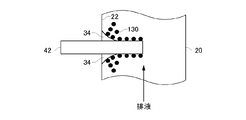
- FIG. 2A is a cross-sectional view showing an example of the suction unit 40.
- the suction unit 40 in this example has a plurality of permanent magnets 42.
- Each permanent magnet 42 is provided so as to be directly insertable into and removable from the pipe 20. Directly removable means that the surface of the permanent magnet 42 inserted into and removed from the pipe 20 is in direct contact with drainage.
- the permanent magnet 42 is partially or entirely inserted into the pipe 20 through a through hole provided in the pipe wall 22 of the pipe 20.
- the length of the permanent magnet 42 inserted into the pipe 20 may be greater than half the diameter of the pipe 20. Also, the length of the permanent magnet 42 inserted into the pipe 20 may be equal to the diameter of the pipe 20. That is, the tip of the permanent magnet 42 may be in contact with the tube wall 22 facing the through hole.
- a combined substance 130 containing magnetic powder is attracted to the surface of the permanent magnet 42 inserted in the pipe 20 by magnetic force.
- the permanent magnet 42 is in the form of a rod having a longitudinal shape.
- the permanent magnet 42 may be cylindrical or prismatic.
- the surface of the permanent magnet 42 may be flat, may be a smooth curved surface, and may be uneven.
- the plurality of permanent magnets 42 may be inserted into the pipe 20 so that the longitudinal direction is orthogonal to the extending direction of the pipe 20. That is, the permanent magnet 42 may be inserted into the pipe 20 so that the longitudinal direction of the permanent magnet 42 is orthogonal to the direction in which the drainage flows. This facilitates installation and removal of the permanent magnet 42.
- the term “orthogonal” or “perpendicular” includes, in addition to the case of being strictly orthogonal or perpendicular, for example, the case of having an error within ⁇ 20 degrees.
- FIG. 2B is a cross-sectional view showing the permanent magnet 42 in the process of being pulled out of the piping 20.
- the area on which the bond 130 can be adsorbed decreases.
- the combined substance 130 adsorbed to the permanent magnet 42 is pushed out into the pipe 20 by the pipe wall 22. For this reason, as the permanent magnet 42 is pulled out of the inside of the pipe 20, the combined substance 130 adsorbed to the permanent magnet 42 is released again into the pipe 20.
- the measurement unit 80 measures the concentration of the bound substance 130 contained in the drainage downstream of the adsorption unit 40. For example, the concentration of the bound material 130 can be estimated by measuring the turbidity or suspended matter concentration.
- the control unit 70 controls the amount of the permanent magnet 42 inserted into the pipe 20 based on the measurement result of the measurement unit 80.
- the control unit 70 according to the present embodiment is provided with piping for the permanent magnet 42 so that the concentration of the combined substance 130 included in the drainage that can flow in the transport unit 10 downstream of the adsorption unit 40 can be maintained within a predetermined allowable range. The amount removed from 20 or the amount removed per unit time may be controlled.
- the amount of permanent magnet 42 capable of appropriately removing the binder 130 contained in the drainage also depends on the flow rate of the drainage.
- the control unit 70 may control the amount of the permanent magnet 42 inserted into the pipe 20 according to at least one of the concentration of the combined substance 130 contained in the drainage and the flow rate of the drainage flowing through the pipe 20.
- the measuring unit 80 may measure the flow rate of the drainage.
- the control unit 70 may use the amount of liquid supplied to the scrubber device 120 per unit time or control data of the pump 68 as information indicating the flow rate of drainage.
- the amount of permanent magnet 42 may refer to the surface area of permanent magnet 42. More specifically, the control unit 70 extracts the number of permanent magnets 42 from the pipe 20 according to the concentration of the combined object 130, the length for extracting each permanent magnet 42 from the pipe 20, and the number of each permanent magnet 42 May be controlled at least one of the speeds at which the pipe 20 is pulled out.
- control unit 70 When removing the permanent magnet 42 from the pipe 20, the control unit 70 preferably extracts the permanent magnet 42 from the pipe 20 in order from the downstream permanent magnet 42. This can prevent the combined substance 130 released from the extracted permanent magnet 42 from being adsorbed again to the other permanent magnet 42.
- FIG. 3A is a cross-sectional view showing another example of the adsorption portion 40 and the pipe 20.
- the pipe wall 22 of the pipe 20 of this embodiment is provided with a plurality of recesses 24 into which the permanent magnet 42 can be inserted and removed.
- the shape of each recess 24 is substantially the same as the permanent magnet 42.
- the longitudinal direction of the recess 24 is perpendicular to the extending direction of the pipe 20.
- the recess 24 is provided so as to extend toward the inside of the pipe 20.
- the permanent magnet 42 of this example can be inserted into and removed from the inside of the pipe 20 but does not directly contact the drainage.
- the surface on the permanent magnet 42 side is referred to as the outer wall, and the surface on the drainage side is referred to as the inner wall.
- the permanent magnet 42 inserted into the recess 24 is covered by the outer surface of the recess 24.
- the magnetic force of the permanent magnet 42 causes the combined object 130 to be adsorbed to the inner wall of the recess 24.
- the inner wall of the recess 24 may be flat, may be a smooth curved surface, and may be uneven. Such a structure also allows the combined object 130 to be held inside the pipe 20.
- FIG. 3B is a cross-sectional view showing the permanent magnet 42 in the process of being pulled out of the recess 24.
- the area of the inner wall of the recess 24 to which the binding material 130 can adsorb decreases. Therefore, as the permanent magnet 42 is pulled out of the recess 24, the combined substance 130 adsorbed on the inner wall of the recess 24 is released again into the pipe 20.
- the recess 24 can be formed integrally with the pipe 20, the sealing performance of the pipe 20 can also be improved.
- the recess 24 may be formed of the same material as the pipe 20, and may be formed of a metal material such as stainless steel or iron.
- the recess 24 may be formed of a resin material or plastic material such as polyvinylidene fluoride or polytetrafluoroethylene. The inner wall of the recess 24 may be subjected to antiseptic treatment.
- the thickness of the wall in the recess 24 corresponds to the distance between the permanent magnet 42 and the drainage.
- the thickness is preferably within 10 mm.
- FIG. 4 is a view showing an arrangement example of the permanent magnet 42.
- the permanent magnet 42 may be inserted and removed directly into the pipe 20 as shown in FIGS. 2A and 2B, or may be inserted and removed from the recess 24 as shown in FIGS. 3A and 3B. .
- the permanent magnet 42 of each example described herein may be in the form shown in FIGS. 2A and 2B, or may be in the form shown in FIGS. 3A and 3B.
- the permanent magnet of this example has one or more first permanent magnets 42-1 and one or more second permanent magnets 42-2.
- the first permanent magnet 42-1 is disposed on the pipe wall 22-1 of the pipe 20 so that the longitudinal direction is orthogonal to the extending direction of the pipe 20.
- the second permanent magnet 42-2 is provided on the pipe wall 22-1 of the pipe 20 at a position different from the first permanent magnet 42-1 in the extending direction of the pipe 20. For example, in the extending direction of the pipe 20, the first permanent magnet 42-1 and the second permanent magnet 42-2 are alternately arranged.
- the second permanent magnet 42-2 is provided on the pipe wall 22-2 opposite to the first permanent magnet 42-1.
- the pipe wall 22-1 and the pipe wall 22-2 in this example are pipe walls facing each other across the center of the pipe 20. Such an arrangement can reduce drainage that passes without contacting the permanent magnet 42. For this reason, the bond 130 can be adsorbed efficiently.
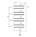
- FIG. 5 is a perspective view showing an example of a position 44 where the permanent magnet 42 is disposed in the pipe 20. As shown in FIG. In addition, the position 44 provided in the surface on the opposite side to the surface of the piping 20 shown in FIG. 5 is shown by a dotted line.
- Each permanent magnet 42 is disposed at a different position in the extending direction of the pipe 20. Further, in the example of FIG. 4, the permanent magnets 42 adjacent in the extending direction of the pipe 20 are provided at positions different by 180 degrees in the cross section of the pipe 20 (that is, the pipe wall 22 on the opposite side) Adjacent permanent magnets 42 are provided at 90 ° different positions in the cross section of the pipe 20. In addition, the installation angle of the adjacent permanent magnet 42 is not limited to said angle. Such an arrangement can further reduce the amount of drainage passing without contacting the permanent magnet 42. For this reason, the bond 130 can be adsorbed more efficiently.
- FIG. 6 is a view showing another arrangement example of the permanent magnet 42.
- the permanent magnet 42 of this example is inserted such that the longitudinal direction is parallel to the extension direction of the transport unit 10 (that is, the direction in which the drainage flows).
- the term "parallel”, in addition to the case of being strictly parallel, includes the case of having an error of, for example, within ⁇ 20 degrees.
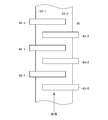
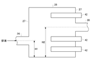
- the conveyance unit 10 in this example is connected with the upstream pipe 26 and the downstream pipe 30 and has a large diameter portion 28 whose diameter is larger than that of the pipe 26 and the pipe 30.
- the large diameter portion 28 has two side surfaces 27 to which the pipe 26 and the pipe 30 are connected.
- the side surface 27 may be a surface substantially perpendicular to the extension direction of the transport unit 10.
- the two side surfaces 27 are disposed to face each other.
- An opening of the pipe 26 is formed on one side surface 27, and an opening of the pipe 30 is formed on the other side surface 27.
- the permanent magnet 42 of this example is provided on the side surface 27 so that the longitudinal direction is perpendicular to the side surface 27.
- the permanent magnet 42 may be provided on the side surface 27 corresponding to the pipe 30 on the downstream side, may be provided on the side surface 27 corresponding to the pipe 26 on the upstream side, and may be provided on both side surfaces 27.
- the length of the permanent magnet 42 can be arranged along the flow of drainage. Therefore, the drainage can be retained for a long time in the magnetic field generated by the permanent magnet 42, and the combined substance 130 can be adsorbed efficiently.
- the opening in the side surface 27 of the pipe 26 and the opening in the side surface 27 of the pipe 30 may be provided at positions not opposed to each other. That is, the heights H1 and H2 of the openings from the predetermined bottom surface of the large diameter portion 28 may be different. Thus, the drainage can be brought into contact with the permanent magnet 42 efficiently.
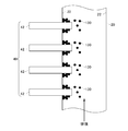
- FIG. 7 is a view showing another arrangement example of the permanent magnet 42.
- the adsorbing portion 40 in the present example has a plurality of permanent magnets 42 disposed along the extending direction of the pipe 20.
- the permanent magnet 42 is disposed on the pipe wall 22 so that the longitudinal direction is orthogonal to the extending direction of the pipe 20.
- the density of the plurality of second permanent magnets 42-2 on the upstream side of the pipe 20 is lower than the density of the plurality of first permanent magnets 42-1 on the downstream side. That is, the arrangement interval P2 of the second permanent magnet 42-2 in at least a part of the upstream side is larger than the arrangement interval P1 of the at least one first permanent magnet 42-1 on the downstream side.
- the combined substance 130 is adsorbed to the permanent magnet 42 on the upstream side, so the concentration of the combined substance 130 in the drainage is lower on the downstream side. Become. For this reason, if the density of the permanent magnet 42 on the downstream side is low, the combined substance 130 may not be sufficiently adsorbed in the drainage, and the combined substance 130 may be refluxed to the scrubber device 120. By increasing the density of the downstream permanent magnet 42 as in this example, it is possible to prevent the combined matter 130 from flowing back to the scrubber device 120.
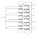
- FIG. 8 is a view showing another arrangement example of the permanent magnet 42.
- the adsorbing portion 40 in the present example has a plurality of permanent magnets 42 disposed along the extending direction of the pipe 20.
- the permanent magnet 42 is disposed on the pipe wall 22 so that the longitudinal direction is orthogonal to the extending direction of the pipe 20.
- the plurality of second permanent magnets 42-2 on the upstream side of the pipe 20 are inserted into the recess 24, as shown in FIGS. 3A and 3B. That is, the hollow 24 corresponding to the second permanent magnet 42-2 is formed in the pipe wall 22 of the pipe 20.
- the first permanent magnet 42-1 at the downstream side of the second permanent magnet 42-2 is directly inserted into and removed from the pipe 20 as shown in FIGS. 2A and 2B. . Since the first permanent magnet 42-1 is directly inserted into the pipe 20, the first permanent magnet 42-1 has a larger adsorptive power to the combination 130 than the second permanent magnet 42-2 and the recess 24. Therefore, the binder 130 can be adsorbed even on the downstream side where the concentration of the binder 130 is low.
- the second permanent magnet 42-2 is disposed on the upstream side where the concentration of the combined substance 130 is high. Therefore, even if the adsorption force is lower than that of the first permanent magnet 42-1, the bond 130 can be sufficiently adsorbed. In addition, since the second permanent magnet 42-2 disposed on the upstream side is less likely to be soiled, maintenance costs can be reduced.
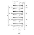
- FIG. 9 is a view showing a configuration example of the pipe 20.
- the pipe 20 of the present example has a plate-like portion 32 extending in a direction different from the extending direction of the pipe 20 in the pipe 20.
- the at least one plate-like portion 32 may extend from the tube wall opposite to the tube wall into which the permanent magnet 42 is inserted to a region sandwiched by the two permanent magnets 42.
- at least one plate-like portion 32 may extend from the tube wall on the same side as the tube wall into which the permanent magnet 42 is inserted, and may be provided so as to be sandwiched by two permanent magnets.
- the plate-like portion 32 may have a width larger than that of the permanent magnet 42.
- Such a structure allows drainage to flow along the longitudinal direction of the permanent magnet 42. Therefore, the drainage can be retained for a long time in the magnetic field generated by the permanent magnet 42, and the combined substance 130 can be efficiently adsorbed.
- the plate-like portion 32 is not provided for the second permanent magnet 42-2 on the upstream side of the pipe 20.
- the plate-like portion 32 is provided for at least a portion of the first permanent magnet 42-1 on the downstream side of the second permanent magnet 42-2.
- the binder 130 can be efficiently adsorbed to the permanent magnet 42 on the downstream side where the concentration of the binder 130 is relatively low.
- FIG. 10 is a cross-sectional view showing a structural example of the pipe 20.
- a protrusion 34 which scrapes off the combined matter 130 adsorbed on the surface of the permanent magnet 42 as the permanent magnet 42 is pulled out of the pipe 20.
- the permanent magnet 42 is directly inserted into and removed from the pipe 20 as shown in FIGS. 2A and 2B.
- the protrusion 34 is formed to project from the tube wall 22 along the surface of the permanent magnet 42 inserted into the pipe 20. At least a portion of the protrusion 34 may be in contact with the surface of the permanent magnet 42, and the entire protrusion 34 may be provided at a slight distance from the surface of the permanent magnet 42.
- the protrusion 34 may have a tapered shape in which the cross-sectional area decreases with distance from the tube wall 22.
- the combination 130 adsorbed on the surface of the permanent magnet 42 is peeled off from the permanent magnet 42 by the projection 34 and re-emitted into the pipe 20.
- the combined substance 130 can be efficiently released into the pipe 20.
- FIG. 11A and 11B are cross-sectional views showing another structural example of the pipe 20.
- the pipe 20 of this example has a valve portion 38 which closes the opening of the pipe wall 22 at the same time when the permanent magnet 42 is completely removed from the pipe 20.
- the valve portion 38 has a shape capable of covering the entire opening of the tube wall 22.
- a seal ring 36 is provided at the end of the tube wall 22 facing the permanent magnet 42.
- the valve portion 38 has a hinge 46 fixed to the tube wall 22.
- the hinge 46 has an elastic force that causes the valve portion 38 to rotate in the direction in which the opening of the tube wall 22 is closed.
- the valve portion 38 is pushed open along the permanent magnet 42.
- the tip of the valve portion 38 contacts the surface of the permanent magnet 42.
- the valve portion 38 may also function as a projection that scrapes off the joint 130 when removing the permanent magnet 42 from the pipe 20.
- the protrusion 34 may be provided around the permanent magnet 42 except for the area where the valve 38 is provided.
- the valve portion 38 may be provided on one side on the upstream side among the four sides surrounding the permanent magnet 42, and the projection 34 may be provided on the other three sides.
- the projection 34 is provided so as not to be in contact with the valve 38 when the valve 38 is opened and closed.
- the protrusion 34 may have a space in the area in which the valve 38 moves.
- the distance between the permanent magnets 42 in the extending direction of the pipe 20 may be 10 mm or more and 100 mm or less. If the distance between the permanent magnets 42 is too small, the permanent magnets 42 easily interfere with each other. When the distance of the permanent magnet 42 is too large, the ability to adsorb the bond 130 is reduced.
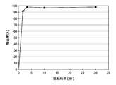
- FIG. 12 is a view showing the relationship between the time during which the permanent magnet 42 is in contact with the drainage and the removal rate of the binder 130 in the drainage.
- one permanent magnet 42 having a length of 300 mm, a diameter of 10 mm and a magnetic force of 1 T was used.
- the permanent magnet 42 was disposed in the pipe 20 having a diameter of 100 mm so that the longitudinal direction was parallel to the extending direction of the pipe.
- the flow rate of the drainage fluid flowing into the piping 20 is 300 mm / sec (contact time 1 sec), 100 mm / sec (contact time 3 sec), 30 mm / sec (contact time 10 sec), 10 mm / sec (contact time 30 sec)
- the removal rate of the bound substance 130 in the drainage was measured.
- the permanent magnet 42 is provided such that the contact time between the permanent magnet 42 and the drainage is 1 second or more.
- control unit 70 may control the amount of the permanent magnet 42 inserted into the pipe 20 according to the flow rate of the drainage. For example, the amount of permanent magnets 42 inserted into the pipe 20 is increased as the flow rate of drainage is faster, and the amount of permanent magnets 42 inserted into the pipe 20 is reduced as the flow rate of drainage is lower. Thereby, an appropriate amount of permanent magnet 42 can be inserted into the pipe 20, and pressure loss due to the presence of the permanent magnet 42 in the drainage can be reduced.
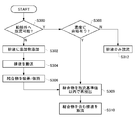
- FIG. 13 is a flowchart showing an outline of the operation of the drainage processing apparatus 100.
- the drainage processing apparatus 100 determines whether drainage can be discharged to the outside. For example, when the drainage processing apparatus 100 is installed on a ship, the control unit 70 determines that the ship is located in the sea area where the drainage containing the bound substance can be discharged and the drainage measured by the measuring unit 80 It is determined that the drainage can be discharged outside when the concentration of the conjugate and the turbidity of the drainage are below the standard value that can be discharged in the relevant sea area.
- the control unit 70 may perform the determination of S300 every predetermined period.
- the drainage processing device 100 controls the drainage from the scrubber device 120 in the addition step S302 to remove magnetic powder, coagulant, and pH adjuster.
- Add additives such as The drainage processing apparatus 100 adds each additive to drainage according to the turbidity of the drainage discharged from the scrubber apparatus 120, the suspended substance concentration and the pH value. In the example shown in FIG. 1, each additive is added to the drainage stored in the tank 60.
- the drainage to which the additive is added is transported in the transport unit 10.
- the drainage may be conveyed to reflux the scrubber device 120.
- the drainage processing apparatus 100 executes the adsorption step S306 together with the transfer step S304.
- the adsorption unit 40 provided in the transport unit 10 adsorbs a combination of the substance to be treated and the magnetic powder contained in the drainage. Further, the bound substance adsorbed is held in the transport unit 10.
- the control unit 70 determines whether there is a margin in the concentration of the conjugate in the drainage and the turbidity of the drainage in the second determination step S308. . That is, the control unit 70 determines whether the concentration and the turbidity of the combined matter in the drainage do not exceed the reference value even if the combined matter adsorbed to the permanent magnet 42 is released again into the drainage.
- the measuring unit 80 may measure the concentration and turbidity of the effluent in the tank 60 or the pipe 20 entering the tank 60. As the reference value, for example, a value corresponding to a legal reference value can be used.
- the control unit 70 may determine an amount capable of re-releasing the conjugate based on the concentration and turbidity of the conjugate in the current drainage. More specifically, the control unit 70 may determine the amount of withdrawal of the permanent magnet 42 from the pipe 20.
- the control unit 70 pulls out the permanent magnet 42 from the pipe 20 and drains the bound substance adsorbed on the permanent magnet 42 Re-release into (S309). In addition, the control unit 70 discharges the drainage from which the combined matter has been re-discharged to the outside of the ship (S310). If it is determined in the second determination step S308 that there is no margin in the concentration of the conjugate and the turbidity in the drainage, the control unit 70 causes only the drainage to be discharged outside the vessel without releasing the conjugate again into the drainage. It is released (S312).
- the drainage liquid from the scrubber device 120 is discharged out of the ship without passing through the transport unit 10 such as the tank 60 or the like. That is, the drainage is discharged out of the vessel without adding magnetic powder and the like.
- suspended substances such as black carbon contained in the drainage from the scrubber device 120 can be efficiently adsorbed.
- the adsorbed substance can be released appropriately.
Abstract
Provided is a liquid discharge treatment device for treating liquid discharge that is discharged from a scrubber device. The liquid discharge treatment device is provided with: a magnetic powder addition unit that adds magnetic powder to the liquid discharge; a conveyance unit that conveys the liquid discharge; and an absorption unit that is provided inside the conveyance unit, and absorbs, and holds therein, a bound substance contained in the liquid discharge, the bound substance including at least the magnetic powder and the substance targeted by the the treatment device. In one example, the absorption unit is able to release the absorbed bound substance into the conveyance unit. In another example, the absorption unit has a permanent magnet that is disposed inside the conveyance unit in a manner which allows for unmediated insertion and retraction. When inserted into the conveyance unit, the permanent magnet absorbs the bound substance, and when retracted from the conveyance unit, releases the bound substance.
Description
本発明は、排液処理装置および排液処理方法に関する。
The present invention relates to a drainage treatment apparatus and a drainage treatment method.
船舶エンジン等の排気ガスに含まれるブラックカーボン等の浮遊物質を除去するスクラバ装置が知られている。スクラバ装置においては、排気ガス中の浮遊物質をスクラバ水に取り込んで排出する。スクラバ装置の排液は、浮遊物質を除去する処理等を行った後、スクラバ装置に還流し、または、外部に放出される。スクラバ装置の排液に含まれる浮遊物質を除去する方法として、遠心分離、膜ろ過および凝集沈殿等の方法が知られている(例えば、特許文献1-3参照)。
特許文献1 特開2004-81933号公報
特許文献2 特開平11-165180号公報
特許文献3 特開2001-129596号公報 There is known a scrubber device that removes floating substances such as black carbon contained in exhaust gas from a ship engine or the like. In the scrubber device, suspended matter in the exhaust gas is taken into scrubber water and discharged. The drainage of the scrubber device is returned to the scrubber device or discharged to the outside after processing for removing suspended solids and the like. As a method of removing suspended solids contained in the drainage of a scrubber device, methods such as centrifugation, membrane filtration, and flocculation are known (see, for example, Patent Documents 1 to 3).
Patent Document 1 Japanese Patent Application Publication No. 2004-81933 Patent Document 2 Japanese Patent Application Publication No. 11-165180 Patent Document 3 Japanese Patent Application Publication No. 2001-129596
遠心分離を用いた除去方法では、装置の消費電力が大きくなってしまう。また、膜ろ過を用いた除去方法では、膜の目詰まりによる膜交換等のメンテナンスの手間がかかる。また、凝集沈殿は、沈殿までに長時間を要する。
In the removal method using centrifugation, the power consumption of the device increases. In addition, in the removal method using membrane filtration, maintenance such as membrane exchange due to clogging of the membrane takes time and effort. In addition, aggregation and precipitation take a long time to precipitate.
第1の態様においては、スクラバ装置から排出される排液を処理する排液処理装置を提供する。排液処理装置は、排液に磁性粉を添加する磁性粉添加部を備えてよい。排液処理装置は、排液を搬送する搬送部を備えてよい。排液処理装置は、搬送部内に設けられ、排液に含まれる、少なくとも処理対象物質と磁性粉を含む結合物を吸着して、搬送部内で保持する吸着部を備えてよい。
In a first aspect, the present invention provides a drainage treatment apparatus for treating drainage discharged from a scrubber device. The drainage treatment apparatus may include a magnetic powder addition unit that adds magnetic powder to the drainage. The drainage treatment apparatus may include a transport unit that transports the drainage. The drainage treatment apparatus may be provided with an adsorption unit which is provided in the transport unit and adsorbs a combined substance containing at least a target substance to be treated and magnetic powder contained in the drainage and held in the transport unit.
吸着部は、吸着した結合物を搬送部内に再放出可能であってよい。吸着部は、搬送部内に直接挿抜可能に設けられた永久磁石を有してよい。永久磁石は、搬送部内に挿入されることで結合物を吸着し、搬送部内から抜かれることで結合物を搬送部内に再放出してよい。
The adsorption unit may be capable of re-releasing the adsorbed bound substance into the transport unit. The adsorption unit may have a permanent magnet provided so as to be directly insertable into and removable from the transport unit. The permanent magnet may adsorb the bound substance by being inserted into the transport section, and may release the bound substance into the transport section by being removed from the inside of the transport section.
吸着部は永久磁石を有してよい。搬送部の管壁は、永久磁石が挿抜可能な窪みを有してよい。永久磁石が窪み内に挿入されることで、窪みの内壁に結合物が吸着し、永久磁石が窪み内から抜かれることで結合物が搬送部内に再放出されてよい。
The adsorption part may have a permanent magnet. The tube wall of the transport may have a recess into which the permanent magnet can be inserted and removed. The permanent magnet may be inserted into the recess so that the combination is adsorbed on the inner wall of the recess and the permanent magnet is removed from the recess so that the combination is re-emitted into the transport section.
永久磁石は、長手を有する棒形状であってよい。永久磁石は、搬送部の延伸方向に対して、長手の方向が直交するように挿入されてよい。
The permanent magnet may be in the form of a rod having a longitudinal. The permanent magnet may be inserted such that the longitudinal direction is orthogonal to the stretching direction of the transport unit.
吸着部は、第1の永久磁石と、搬送部の延伸方向において第1の永久磁石とは異なる位置に設けられ、且つ、第1の永久磁石とは逆側の管壁に設けられた第2の永久磁石とを有してよい。
The adsorption unit is provided at a position different from the first permanent magnet in the extending direction of the first permanent magnet and the transport unit, and is provided on a tube wall opposite to the first permanent magnet. And a permanent magnet.
吸着部は、搬送部内に直接挿抜可能に設けられた第1の永久磁石を有してよい。吸着部は、搬送部において第1の永久磁石よりも上流側に設けられた第2の永久磁石を有してよい。搬送部の管壁は、第2の永久磁石が挿抜可能な窪みを有してよい。
The adsorption unit may have a first permanent magnet provided to be directly insertable into and removable from the transport unit. The adsorption unit may have a second permanent magnet provided upstream of the first permanent magnet in the transport unit. The tube wall of the transport may have a recess into which the second permanent magnet can be inserted and removed.
吸着部は、複数の永久磁石を有してよい。搬送部の上流側における永久磁石の密度が、搬送部の下流側における永久磁石の密度よりも低くてよい。
The adsorption part may have a plurality of permanent magnets. The density of the permanent magnet upstream of the transport may be lower than the density of the permanent magnet downstream of the transport.
永久磁石は、長手を有する棒形状であってよい。永久磁石は、搬送部の延伸方向に対して、長手の方向が平行となるように挿入されてよい。
The permanent magnet may be in the form of a rod having a longitudinal. The permanent magnet may be inserted such that the longitudinal direction is parallel to the extending direction of the transport unit.
搬送部は、上流側および下流側の配管よりも径の大きい大径部を有してよい。大径部は、上流側および下流側の配管の開口が形成される側面を有してよい。永久磁石は、大径部の側面に設けられてよい。
The transport unit may have a large diameter portion with a larger diameter than the upstream and downstream pipes. The large diameter portion may have side surfaces on which the openings of the upstream and downstream pipes are formed. The permanent magnet may be provided on the side of the large diameter portion.
排液処理装置は、吸着部よりも下流側の搬送部内をながれる排液に含まれる結合物の濃度を測定する測定部を更に備えてよい。測定部は、排液の流速を測定してもよい。排液処理装置は、測定部における測定結果に基づいて、搬送部または窪みに挿入する永久磁石の量を制御する制御部を更に備えてよい。
The drainage treatment apparatus may further include a measurement unit that measures the concentration of the bound substance contained in the drainage that can flow in the transport unit downstream of the adsorption unit. The measuring unit may measure the flow rate of the drainage. The drainage treatment apparatus may further include a control unit that controls the amount of permanent magnet inserted into the transport unit or the recess based on the measurement result in the measurement unit.
結合物を含む排液を外部に排出する場合に、制御部は、測定部が測定した結合物の濃度が許容範囲内に維持されるように、吸着部に結合物を再放出させてよい。制御部は、吸着部に結合物を再放出させる場合に、下流側の吸着部から順番に結合物を再放出させてよい。
When the drainage containing the conjugate is discharged to the outside, the control unit may re-release the conjugate to the adsorption unit so that the concentration of the conjugate measured by the measurement unit is maintained within the allowable range. The control unit may re-emit the binder sequentially from the downstream adsorption unit when the binder is re-released to the adsorption unit.
搬送部の内壁には、永久磁石が搬送部から抜かれるに従い、永久磁石の表面に吸着した結合物を掻き落とす突起部が設けられていてよい。搬送部の内壁には、永久磁石が搬送部から抜かれるのに伴い、永久磁石が挿入されていた開口を塞ぐ弁が設けられていてよい。
The inner wall of the transport unit may be provided with a projection that scrapes off a substance adsorbed on the surface of the permanent magnet as the permanent magnet is removed from the transport unit. The inner wall of the transfer unit may be provided with a valve that closes the opening in which the permanent magnet was inserted as the permanent magnet is removed from the transfer unit.
第2の態様においては、スクラバ装置から排出される排液を処理する排液処理方法であって、排液に磁性粉を添加する磁性粉添加段階と、磁性粉が添加された排液を搬送部で搬送する搬送段階と、搬送部内に設けた吸着部で、排液に含まれる処理対象物質と磁性粉との結合物を吸着し、搬送部内で保持する吸着段階とを備える排液処理方法を提供する。
In the second aspect, there is provided a drainage treatment method for treating drainage discharged from a scrubber device, wherein a magnetic powder addition step of adding magnetic powder to the drainage, and drainage of the waste liquid to which the magnetic powder is added A drainage treatment method comprising: a conveying step of conveying by a part; and an adsorbing step of adsorbing a combined substance of a target substance to be treated and magnetic powder contained in the drainage by an adsorbing unit provided in the conveying unit I will provide a.
なお、上記の発明の概要は、本発明の特徴の全てを列挙したものではない。また、これらの特徴群のサブコンビネーションもまた、発明となりうる。
The above summary of the invention does not enumerate all of the features of the present invention. In addition, a subcombination of these feature groups can also be an invention.
以下、発明の実施の形態を通じて本発明を説明するが、以下の実施形態は請求の範囲にかかる発明を限定するものではない。また、実施形態の中で説明されている特徴の組み合わせの全てが発明の解決手段に必須であるとは限らない。
Hereinafter, the present invention will be described through the embodiments of the invention, but the following embodiments do not limit the invention according to the claims. Moreover, not all combinations of features described in the embodiments are essential to the solution of the invention.
図1は、本発明の一つの実施形態に係る排液処理装置100を、排ガス源110およびスクラバ装置120と共に示す図である。排ガス源110は、船舶に設けられるエンジン等である。排ガス源110が排出する排ガスには、ブラックカーボン等の浮遊物質が含まれる。
FIG. 1 is a view showing a drainage treatment apparatus 100 according to an embodiment of the present invention, together with an exhaust gas source 110 and a scrubber apparatus 120. The exhaust gas source 110 is an engine or the like provided on a ship. The exhaust gas emitted by the exhaust gas source 110 contains suspended substances such as black carbon.
スクラバ装置120は、船舶等に設置されて、排ガス源110が排出する排ガスを処理する。スクラバ装置120は、排ガスが通過する塔内において海水等の液体を噴霧することで、排ガス中の浮遊物質を液体中に取り込む。スクラバ装置120は、浮遊物質を取り込んだ排液を、排液処理装置100に排出する。
The scrubber device 120 is installed on a ship or the like to treat the exhaust gas emitted by the exhaust gas source 110. The scrubber apparatus 120 takes in suspended substances in the exhaust gas into the liquid by spraying a liquid such as seawater in a tower through which the exhaust gas passes. The scrubber device 120 discharges the drainage that has taken in the suspended matter to the drainage processing device 100.
排液処理装置100は、搬送部10、磁性粉添加部62、pH調整部64、凝集剤添加部66、制御部70および測定部80を備える。搬送部10は、スクラバ装置120の排液を搬送する。搬送部10は、排液をスクラバ装置120で再利用すべく、排液に所定の処理を施してスクラバ装置120に還流させてよく、所定の処理を施した排液を船舶等の外部に排出させてもよい。
The drainage treatment apparatus 100 includes a conveyance unit 10, a magnetic powder addition unit 62, a pH adjustment unit 64, a coagulant addition unit 66, a control unit 70, and a measurement unit 80. The transport unit 10 transports the drainage of the scrubber device 120. The transport unit 10 may subject the drainage to a predetermined treatment and recycle the drainage to the scrubber device 120 in order to reuse the drainage in the scrubber device 120, and drain the drainage subjected to the predetermined treatment to the outside of a ship or the like. You may
本例の搬送部10は、配管20、タンク60、ポンプ68および吸着部40を有する。タンク60は、配管20によりスクラバ装置120と接続される。タンク60は、スクラバ装置120の排液を滞留させて、所定の処理を行う。
The transport unit 10 in this example includes a pipe 20, a tank 60, a pump 68, and a suction unit 40. The tank 60 is connected to the scrubber device 120 by a pipe 20. The tank 60 holds the drainage of the scrubber device 120 and performs predetermined processing.
磁性粉添加部62は、スクラバ装置120の排液に磁性粉を添加する。本例の磁性粉添加部62は、タンク60に磁性粉を投入する。磁性粉添加部62は、磁性粉を直接タンク60に投入してよく、磁性粉を含む液体をタンク60に投入してもよい。タンク60には、撹拌機能が設けられることが好ましい。これにより、排液中の処理対象物質の少なくとも一部と、磁性粉とが結合する。
The magnetic powder addition unit 62 adds the magnetic powder to the drainage of the scrubber device 120. The magnetic powder addition unit 62 of the present embodiment charges the magnetic powder into the tank 60. The magnetic powder addition unit 62 may directly charge the magnetic powder into the tank 60 or may charge a liquid containing the magnetic powder into the tank 60. The tank 60 is preferably provided with a stirring function. As a result, at least a part of the target substance to be treated in the drainage is bound to the magnetic powder.
磁性粉は、ブラックカーボン等の処理対象物質と結合可能な材料で形成される。磁性粉は、常磁性体および強磁性体のいずれであってもよい。一例として磁性粉は、四酸化三鉄等の酸化鉄、コバルト、酸化クロム、フェライト、またはこれらの混合物である。磁性体の粒径は、0.05μm以上、10μm以下であってよく、0.05μm以上、5μm以下であってもよい。
The magnetic powder is formed of a material capable of binding to the substance to be treated such as black carbon. The magnetic powder may be either paramagnetic or ferromagnetic. As an example, the magnetic powder is iron oxide such as triiron tetraoxide, cobalt, chromium oxide, ferrite, or a mixture thereof. The particle size of the magnetic substance may be 0.05 μm or more and 10 μm or less, and may be 0.05 μm or more and 5 μm or less.
磁性粉の保磁力は、104/4πA/m以上、4×105/4πA/m以下であってよく、2×105/4πA/m以上、3×105/4πA/m以下であってもよい。磁性粉の添加量は、処理対象物質に対する質量比で0.1以上、10以下であってよく、0.5以上、5以下であってもよい。
The coercive force of the magnetic powder may be 10 4 / 4πA / m or more and 4 × 10 5 / 4πA / m or less, and 2 × 10 5 / 4πA / m or more and 3 × 10 5 / 4πA / m or less May be The addition amount of the magnetic powder may be 0.1 or more and 10 or less, or may be 0.5 or more and 5 or less in mass ratio with respect to the substance to be treated.
磁性粉の添加量が上述した範囲より少ないと、処理対象物質と磁性粉を含む結合物を形成する効率が悪くなる。結合物の一例として、処理対象物質および磁性粉が凝集剤により凝集した磁性フロックが挙げられるが、結合物は凝集剤を含むものに限定されない。結合物は、少なくとも処理対象物質と磁性粉とを含んでいればよい。また、磁性粉の添加量が上述した範囲より多いと、磁性粉を過剰に添加することになり、無駄になる磁性粉が増加する。
If the amount of the magnetic powder added is smaller than the above-mentioned range, the efficiency of forming a combination containing the substance to be treated and the magnetic powder is deteriorated. An example of the combination is a magnetic floc in which the substance to be treated and the magnetic powder are aggregated by the aggregating agent, but the combination is not limited to one including the aggregating agent. The combined substance may contain at least the substance to be treated and the magnetic powder. In addition, when the addition amount of the magnetic powder is larger than the above-mentioned range, the magnetic powder is excessively added, and the magnetic powder to be wasted increases.
制御部70は、スクラバ装置120の排液に含まれる処理対象物質の濃度に応じて、磁性粉添加部62がタンク60に投入する磁性粉の量を制御してよい。処理対象物質の濃度は、スクラバ装置120の排液の濁度または浮遊物質(SS:Suspended Solids)の濃度(以下、「浮遊物質濃度」とする。)から推定できる。測定部80は、スクラバ装置120の排液の濁度または浮遊物質濃度を測定してよい。例えば排液の濁度は、JIS K0101の9.3に準拠した方法などによって測定できる。また、排液の浮遊物質濃度は、JIS K0102の14.1に準拠した方法などによって測定できる。制御部70は、排液の濁度および/または浮遊物質濃度と、投入すべき磁性粉量との関係を示す情報を予め記憶してよい。
The control unit 70 may control the amount of the magnetic powder charged into the tank 60 by the magnetic powder addition unit 62 in accordance with the concentration of the process target substance contained in the drainage of the scrubber device 120. The concentration of the substance to be treated can be estimated from the turbidity of the drainage of the scrubber device 120 or the concentration of suspended solids (SS: Suspended Solids) (hereinafter referred to as “suspended solids concentration”). The measuring unit 80 may measure the turbidity or suspended substance concentration of the drainage of the scrubber device 120. For example, the turbidity of the effluent can be measured by a method according to JIS K 0101 9.3. Further, the suspended matter concentration of the drainage can be measured by a method in accordance with JIS K 0102 14.1 or the like. The control unit 70 may store in advance information indicating the relationship between the turbidity of the drainage and / or the suspended substance concentration and the amount of magnetic powder to be charged.
凝集剤添加部66は、スクラバ装置120の排液に凝集剤を添加する。本例の凝集剤添加部66は、タンク60に凝集剤を投入する。タンク60に磁性粉および凝集剤を投入することで、磁性粉および処理対象物質を含む磁性フロックが形成される。これにより、磁性粉および処理対象物質の結合物の生成を促進できる。
The coagulant addition unit 66 adds the coagulant to the drainage of the scrubber device 120. The coagulant addition part 66 of the present example supplies the coagulant to the tank 60. By charging the magnetic powder and the coagulant into the tank 60, magnetic flock containing the magnetic powder and the substance to be treated is formed. This can promote the formation of a combination of the magnetic powder and the substance to be treated.
凝集剤の材料は、一例としてポリ塩化アルミニウム、ポリ硫酸第二鉄、硫酸アルミニウム、高分子材料またはこれらの混合物である。高分子材料は、例えばノニオン系、カチオン系、アニオン系または両性である。凝集剤の添加量は、処理対象物質1質量部当たり0.005以上、1以下であってよく、0.01以上、0.5以下であってもよい。
The material of the flocculant is, by way of example, polyaluminum chloride, polyferric sulfate, aluminum sulfate, polymeric materials or mixtures thereof. The polymeric material is, for example, nonionic, cationic, anionic or amphoteric. The addition amount of the aggregating agent may be 0.005 or more and 1 or less, or may be 0.01 or more and 0.5 or less per 1 mass part of the substance to be treated.
凝集剤の添加量が上述した範囲より少ないと、磁性フロックを形成する効率が悪くなる。また、凝集剤の添加量が上述した範囲より多いと、凝集剤を過剰に添加することになり、無駄になる凝集剤が増加する。
If the addition amount of the coagulant is smaller than the above-mentioned range, the efficiency of forming the magnetic floc deteriorates. In addition, when the addition amount of the coagulant is larger than the above-described range, the coagulant is excessively added, and the amount of the coagulant to be wasted increases.
制御部70は、スクラバ装置120から単位時間当たりに排出される排液に含まれる処理対象物質の濃度に応じて、凝集剤添加部66がタンク60に投入する凝集剤の量を制御してよい。測定部80は、スクラバ装置120の排液の濁度または浮遊物質濃度を測定してよい。測定方法としては、上記のJIS K0101の9.3に準拠した方法、JIS K0102の14.1に準拠した方法などを用いることができる。制御部70は、排液の濁度および/または浮遊物質濃度と、投入すべき凝集剤量との関係を示す情報を予め記憶してよい。
The control unit 70 may control the amount of the coagulant added to the tank 60 by the coagulant addition unit 66 in accordance with the concentration of the substance to be treated contained in the drainage discharged per unit time from the scrubber device 120 . The measuring unit 80 may measure the turbidity or suspended substance concentration of the drainage of the scrubber device 120. As a measuring method, the method according to 9.3 of said JIS K 0101, the method according to 14.1 of JIS K 0102, etc. can be used. The control unit 70 may store in advance information indicating the relationship between the turbidity of the drainage and / or the suspended substance concentration and the amount of flocculant to be charged.
pH調整部64は、スクラバ装置120の排液のpHを調整する。本例のpH調整部64は、タンク60にpH調整剤を投入する。pH調整部64は、排液のpHが4以上、11以下となるように、排液のpHを調整してよい。排液のpHを調整することで、凝集剤が消費するアルカリを補償することができる。
The pH adjusting unit 64 adjusts the pH of the drainage of the scrubber device 120. The pH adjusting unit 64 of the present embodiment charges the tank 60 with the pH adjusting agent. The pH adjusting unit 64 may adjust the pH of the drainage so that the pH of the drainage becomes 4 or more and 11 or less. By adjusting the pH of the drainage, the alkali consumed by the flocculant can be compensated.
タンク60において磁性粉が添加された排液は、配管20を介して吸着部40に搬送される。タンク60および吸着部40の間には、排液をタンク60から吸引するためのポンプ68が設けられていてもよい。
The drainage liquid to which the magnetic powder is added in the tank 60 is conveyed to the adsorption unit 40 through the pipe 20. A pump 68 for suctioning drainage from the tank 60 may be provided between the tank 60 and the adsorption unit 40.
吸着部40は、搬送部10内に設けられる。吸着部40は、排液に含まれる処理対象物質と磁性粉との結合物を吸着する。吸着部40は、磁場を発生して結合物を吸着する。吸着部40は、永久磁石を有することが好ましい。永久磁石を用いることで、電力等のエネルギー消費を抑制することができる。ただし、吸着部40は、電磁石等で磁場を発生してもよい。
The suction unit 40 is provided in the transport unit 10. The adsorption unit 40 adsorbs a combination of the target substance to be treated and the magnetic powder contained in the drainage. The adsorption unit 40 generates a magnetic field to adsorb the bound substance. It is preferable that the adsorption part 40 has a permanent magnet. By using a permanent magnet, energy consumption such as power can be suppressed. However, the adsorption unit 40 may generate a magnetic field by an electromagnet or the like.
吸着部40は、結合物を搬送部10内で保持する。搬送部10内とは、スクラバ装置120が動作している場合に、排液が継続的に流れる領域を指す。本例の吸着部40は、吸着した結合物を排液に曝しながら保持する。吸着部40は、配管20の内部に設けられてよく、タンク60の内部に設けられてもよい。搬送部10は、上流側の配管20により排液が流入し、下流側の配管20により排液が流出する、配管20よりも径の大きい大径部を有してよい。吸着部40は、当該大径部の内部に設けられてもよい。
The adsorption unit 40 holds the combined substance in the transport unit 10. The inside of the transport unit 10 refers to a region in which drainage flows continuously when the scrubber device 120 is in operation. The adsorbing unit 40 of this example holds the adsorbed binder while exposing it to the drainage. The adsorbing unit 40 may be provided inside the pipe 20 or may be provided inside the tank 60. The transport unit 10 may have a large diameter portion having a larger diameter than the pipe 20, from which the drainage liquid flows in through the piping 20 on the upstream side and the drainage flows out through the piping 20 on the downstream side. The adsorption part 40 may be provided inside the large diameter part.
吸着部40は、通過した排液が船舶等の外部に排出可能である領域に設けられる。本例では分岐点11において、船舶等の外部に排液を排出する配管20と、スクラバ装置120に接続される配管20とに配管20が分岐する。この場合、タンク60から分岐点11までの搬送部10に、吸着部40が配置される。
The adsorption part 40 is provided in the area | region which can discharge | emit the discharged | emitted liquid which passed through the exterior of ships etc. FIG. In this example, at the branch point 11, the pipe 20 branches into a pipe 20 for discharging the drainage to the outside of the ship or the like and a pipe 20 connected to the scrubber device 120. In this case, a suction unit 40 is disposed in the transport unit 10 from the tank 60 to the branch point 11.
吸着部40は、吸着した結合物を、搬送部10内に再放出可能に設けられる。これにより、結合物を含む排液を船舶等の外部に排出可能となった場合に、一時的に保持していた結合物を容易に排液中に再放出して、船舶等の外部に排出することができる。例えば、船舶が航行または停泊している海域によっては、所定の濃度の結合物を含む排液を船外に排出可能な場合がある。制御部70は、船舶の現在位置に基づいて、吸着部40に結合物を再放出させてよい。さらには浄化されたスクラバ装置120の排液の濁度または浮遊物質濃度が法的基準値以下となっている場合に、船舶等の外部の海域に排出することができる。
The adsorbing unit 40 is provided so as to be able to re-emit the adsorbed substance into the transport unit 10. As a result, when it becomes possible to discharge the drainage containing the bound substance to the outside of the ship or the like, the temporarily held bound substance is easily re-discharged into the drainage and drained to the outside of the ship or the like. can do. For example, depending on the sea area in which the vessel is traveling or berth, it may be possible to discharge drainage containing bound matter of a predetermined concentration overboard. The control unit 70 may cause the adsorbing unit 40 to release the bound substance again based on the current position of the ship. Furthermore, when the turbidity or suspended solids concentration of the drainage of the scrubber device 120 that has been purified is below the legal standard value, it can be discharged to an external sea area such as a ship.
図2Aは、吸着部40の一例を示す断面図である。本例の吸着部40は、複数の永久磁石42を有する。それぞれの永久磁石42は、配管20内に直接挿抜可能に設けられる。直接挿抜可能とは、配管20内に挿抜される永久磁石42の表面が排液に直接接触することを指す。
FIG. 2A is a cross-sectional view showing an example of the suction unit 40. As shown in FIG. The suction unit 40 in this example has a plurality of permanent magnets 42. Each permanent magnet 42 is provided so as to be directly insertable into and removable from the pipe 20. Directly removable means that the surface of the permanent magnet 42 inserted into and removed from the pipe 20 is in direct contact with drainage.
永久磁石42は、配管20の管壁22に設けられた貫通孔を通って、配管20内に一部分または全体が挿入される。配管20内に挿入される永久磁石42の長さは、配管20の直径の半分より大きくてよい。また、配管20内に挿入される永久磁石42の長さは、配管20の直径と等しくてもよい。つまり、永久磁石42の先端は、貫通孔と対向する管壁22に接触してよい。
The permanent magnet 42 is partially or entirely inserted into the pipe 20 through a through hole provided in the pipe wall 22 of the pipe 20. The length of the permanent magnet 42 inserted into the pipe 20 may be greater than half the diameter of the pipe 20. Also, the length of the permanent magnet 42 inserted into the pipe 20 may be equal to the diameter of the pipe 20. That is, the tip of the permanent magnet 42 may be in contact with the tube wall 22 facing the through hole.
図2Aに示すように、配管20内に挿入された永久磁石42の表面には、磁性粉を含む結合物130が磁力により吸着する。永久磁石42は、長手を有する棒形状である。永久磁石42は、円柱状であってよく、角柱状であってもよい。また、永久磁石42の表面は平坦であってよく、なめらかな曲面であってよく、凹凸が形成されていてもよい。
As shown in FIG. 2A, a combined substance 130 containing magnetic powder is attracted to the surface of the permanent magnet 42 inserted in the pipe 20 by magnetic force. The permanent magnet 42 is in the form of a rod having a longitudinal shape. The permanent magnet 42 may be cylindrical or prismatic. Moreover, the surface of the permanent magnet 42 may be flat, may be a smooth curved surface, and may be uneven.
複数の永久磁石42は、配管20の延伸方向に対して、長手の方向が直交するように、配管20内に挿入されてよい。つまり、排液が流れる方向に対して、永久磁石42の長手が直交するように、配管20内に挿入されてよい。これにより、永久磁石42の設置および挿抜が容易になる。なお直交または垂直とは、厳密に直交または垂直である場合に加え、例えば±20度以内の誤差を有する場合を含む。
The plurality of permanent magnets 42 may be inserted into the pipe 20 so that the longitudinal direction is orthogonal to the extending direction of the pipe 20. That is, the permanent magnet 42 may be inserted into the pipe 20 so that the longitudinal direction of the permanent magnet 42 is orthogonal to the direction in which the drainage flows. This facilitates installation and removal of the permanent magnet 42. The term “orthogonal” or “perpendicular” includes, in addition to the case of being strictly orthogonal or perpendicular, for example, the case of having an error within ± 20 degrees.
図2Bは、配管20内から抜かれる途中の永久磁石42を示す断面図である。配管20内に存在する永久磁石42の長さが減少すると、結合物130が吸着できる面積が減少する。また、永久磁石42に吸着していた結合物130は、管壁22により配管20中に押し出される。このため、永久磁石42が配管20内から抜かれるのに伴って、永久磁石42に吸着していた結合物130が、配管20内に再放出される。
FIG. 2B is a cross-sectional view showing the permanent magnet 42 in the process of being pulled out of the piping 20. As shown in FIG. As the length of the permanent magnet 42 present in the pipe 20 decreases, the area on which the bond 130 can be adsorbed decreases. Further, the combined substance 130 adsorbed to the permanent magnet 42 is pushed out into the pipe 20 by the pipe wall 22. For this reason, as the permanent magnet 42 is pulled out of the inside of the pipe 20, the combined substance 130 adsorbed to the permanent magnet 42 is released again into the pipe 20.
測定部80は、吸着部40よりも下流側における排液に含まれる結合物130の濃度を測定する。例えば、結合物130の濃度は、濁度または浮遊物質濃度を測定することで推定できる。制御部70は、測定部80における測定結果に基づいて、配管20に挿入する永久磁石42の量を制御する。本例の制御部70は、吸着部40よりも下流側の搬送部10内をながれる排液に含まれる結合物130の濃度を、所定の許容範囲内に維持できるように、永久磁石42を配管20から抜く量、または、単位時間当たりに抜く量を制御してよい。
The measurement unit 80 measures the concentration of the bound substance 130 contained in the drainage downstream of the adsorption unit 40. For example, the concentration of the bound material 130 can be estimated by measuring the turbidity or suspended matter concentration. The control unit 70 controls the amount of the permanent magnet 42 inserted into the pipe 20 based on the measurement result of the measurement unit 80. The control unit 70 according to the present embodiment is provided with piping for the permanent magnet 42 so that the concentration of the combined substance 130 included in the drainage that can flow in the transport unit 10 downstream of the adsorption unit 40 can be maintained within a predetermined allowable range. The amount removed from 20 or the amount removed per unit time may be controlled.
また、排液に含まれる結合物130を適切に除去できる永久磁石42の量は、排液の流速にも依存する。制御部70は、排液に含まれる結合物130の濃度、および、配管20を流れる排液の流速の少なくとも一方に応じて、配管20に挿入する永久磁石42の量を制御してもよい。測定部80は、排液の流速を測定してよい。制御部70は、スクラバ装置120に単位時間当たりに供給される液体の量、または、ポンプ68の制御データを、排液の流速を示す情報として用いてもよい。
In addition, the amount of permanent magnet 42 capable of appropriately removing the binder 130 contained in the drainage also depends on the flow rate of the drainage. The control unit 70 may control the amount of the permanent magnet 42 inserted into the pipe 20 according to at least one of the concentration of the combined substance 130 contained in the drainage and the flow rate of the drainage flowing through the pipe 20. The measuring unit 80 may measure the flow rate of the drainage. The control unit 70 may use the amount of liquid supplied to the scrubber device 120 per unit time or control data of the pump 68 as information indicating the flow rate of drainage.
永久磁石42の量とは、永久磁石42の表面積を指してよい。より具体的には、制御部70は、結合物130の濃度に応じて、永久磁石42を配管20から抜く本数、それぞれの永久磁石42を配管20から抜く長さ、および、それぞれの永久磁石42を配管20から抜く速度の少なくとも一つを制御してよい。
The amount of permanent magnet 42 may refer to the surface area of permanent magnet 42. More specifically, the control unit 70 extracts the number of permanent magnets 42 from the pipe 20 according to the concentration of the combined object 130, the length for extracting each permanent magnet 42 from the pipe 20, and the number of each permanent magnet 42 May be controlled at least one of the speeds at which the pipe 20 is pulled out.
配管20から永久磁石42を抜く場合、制御部70は、下流側の永久磁石42から順番に、配管20から抜き出すことが好ましい。これにより、抜き出した永久磁石42から放出された結合物130が、他の永久磁石42に再度吸着することを防ぐことができる。
When removing the permanent magnet 42 from the pipe 20, the control unit 70 preferably extracts the permanent magnet 42 from the pipe 20 in order from the downstream permanent magnet 42. This can prevent the combined substance 130 released from the extracted permanent magnet 42 from being adsorbed again to the other permanent magnet 42.
図3Aは、吸着部40および配管20の他の例を示す断面図である。本例の配管20の管壁22には、永久磁石42が挿抜可能な複数の窪み24が設けられる。それぞれの窪み24の形状は、永久磁石42とほぼ同一である。本例において窪み24の長手方向は、配管20の延伸方向に対して垂直である。
FIG. 3A is a cross-sectional view showing another example of the adsorption portion 40 and the pipe 20. As shown in FIG. The pipe wall 22 of the pipe 20 of this embodiment is provided with a plurality of recesses 24 into which the permanent magnet 42 can be inserted and removed. The shape of each recess 24 is substantially the same as the permanent magnet 42. In the present embodiment, the longitudinal direction of the recess 24 is perpendicular to the extending direction of the pipe 20.
窪み24は、配管20の内部に向かって延伸して設けられる。本例の永久磁石42は、配管20の内部に挿抜可能であるが、排液とは直接接触しない。窪み24のうち、永久磁石42側の面を外壁、排液側の面を内壁と称する。窪み24に挿入された永久磁石42は、窪み24の外面に覆われる。
The recess 24 is provided so as to extend toward the inside of the pipe 20. The permanent magnet 42 of this example can be inserted into and removed from the inside of the pipe 20 but does not directly contact the drainage. Of the depressions 24, the surface on the permanent magnet 42 side is referred to as the outer wall, and the surface on the drainage side is referred to as the inner wall. The permanent magnet 42 inserted into the recess 24 is covered by the outer surface of the recess 24.
窪み24に永久磁石42が挿入されると、永久磁石42の磁力により、窪み24の内壁に結合物130が吸着する。窪み24の内壁は、平坦であってよく、なめらかな曲面であってよく、凹凸が形成されていてもよい。このような構造によっても、配管20の内部に結合物130を保持することができる。
When the permanent magnet 42 is inserted into the recess 24, the magnetic force of the permanent magnet 42 causes the combined object 130 to be adsorbed to the inner wall of the recess 24. The inner wall of the recess 24 may be flat, may be a smooth curved surface, and may be uneven. Such a structure also allows the combined object 130 to be held inside the pipe 20.
図3Bは、窪み24内から抜かれる途中の永久磁石42を示す断面図である。窪み24内に存在する永久磁石42の長さが減少すると、結合物130が吸着できる窪み24の内壁の面積が減少する。このため、永久磁石42が窪み24内から抜かれるのに伴って、窪み24の内壁に吸着していた結合物130が、配管20内に再放出される。
FIG. 3B is a cross-sectional view showing the permanent magnet 42 in the process of being pulled out of the recess 24. As shown in FIG. As the length of the permanent magnet 42 present in the recess 24 decreases, the area of the inner wall of the recess 24 to which the binding material 130 can adsorb decreases. Therefore, as the permanent magnet 42 is pulled out of the recess 24, the combined substance 130 adsorbed on the inner wall of the recess 24 is released again into the pipe 20.
図3Aおよび図3Bの例によれば、永久磁石42が排液に曝されないので、永久磁石42の保守が容易になる。また、窪み24は配管20と一体に形成できるので、配管20の密閉性も向上させることができる。窪み24は、配管20と同一の材料で形成されてよく、ステンレスまたは鉄等の金属材料で形成されてもよい。また、窪み24は、ポリフッ化ビニリデンまたはポリテトラフルオロエチレン等の樹脂材料またはプラスチック材料で形成されてもよい。窪み24の内壁は、防腐防食処理されてもよい。
According to the example of FIGS. 3A and 3B, maintenance of permanent magnet 42 is facilitated because permanent magnet 42 is not exposed to drainage. In addition, since the recess 24 can be formed integrally with the pipe 20, the sealing performance of the pipe 20 can also be improved. The recess 24 may be formed of the same material as the pipe 20, and may be formed of a metal material such as stainless steel or iron. Also, the recess 24 may be formed of a resin material or plastic material such as polyvinylidene fluoride or polytetrafluoroethylene. The inner wall of the recess 24 may be subjected to antiseptic treatment.
また、窪み24における壁の厚みは、永久磁石42と排液との距離に対応する。当該厚みが増大すると、結合物130に及ぶ磁力が低下するので、当該厚みは10mm以内であることが好ましい。
Also, the thickness of the wall in the recess 24 corresponds to the distance between the permanent magnet 42 and the drainage. When the thickness is increased, the magnetic force applied to the bond 130 is reduced, so the thickness is preferably within 10 mm.
図4は、永久磁石42の配置例を示す図である。なお、永久磁石42は、図2AおよびBに示すように配管20内に直接挿抜される形態であってよく、図3Aおよび図3Bに示すように窪み24に挿抜される形態であってもよい。本明細書で説明する各例の永久磁石42は、特に指定が無ければ、図2Aおよび図2Bに示す形態であってよく、図3Aおよび図3Bに示す形態であってもよい。
FIG. 4 is a view showing an arrangement example of the permanent magnet 42. As shown in FIG. The permanent magnet 42 may be inserted and removed directly into the pipe 20 as shown in FIGS. 2A and 2B, or may be inserted and removed from the recess 24 as shown in FIGS. 3A and 3B. . Unless otherwise specified, the permanent magnet 42 of each example described herein may be in the form shown in FIGS. 2A and 2B, or may be in the form shown in FIGS. 3A and 3B.
本例の永久磁石は、1以上の第1の永久磁石42-1と、1以上の第2の永久磁石42-2とを有する。第1の永久磁石42-1は、配管20の延伸方向に対して長手方向が直交するように、配管20の管壁22-1に配置される。第2の永久磁石42-2は、配管20の管壁22-1に、配管20の延伸方向において第1の永久磁石42-1とは異なる位置に設けられる。例えば、配管20の延伸方向において、第1の永久磁石42-1および第2の永久磁石42-2は交互に配置される。
The permanent magnet of this example has one or more first permanent magnets 42-1 and one or more second permanent magnets 42-2. The first permanent magnet 42-1 is disposed on the pipe wall 22-1 of the pipe 20 so that the longitudinal direction is orthogonal to the extending direction of the pipe 20. The second permanent magnet 42-2 is provided on the pipe wall 22-1 of the pipe 20 at a position different from the first permanent magnet 42-1 in the extending direction of the pipe 20. For example, in the extending direction of the pipe 20, the first permanent magnet 42-1 and the second permanent magnet 42-2 are alternately arranged.
また、第2の永久磁石42-2は、第1の永久磁石42-1とは逆側の管壁22-2に設けられる。本例の管壁22-1および管壁22-2は、配管20の中心を挟んで対向する管壁である。このような配置により、永久磁石42に接しないで通過する排液を減少させることができる。このため、結合物130を効率よく吸着することができる。
Further, the second permanent magnet 42-2 is provided on the pipe wall 22-2 opposite to the first permanent magnet 42-1. The pipe wall 22-1 and the pipe wall 22-2 in this example are pipe walls facing each other across the center of the pipe 20. Such an arrangement can reduce drainage that passes without contacting the permanent magnet 42. For this reason, the bond 130 can be adsorbed efficiently.
図5は、配管20において永久磁石42が配置される位置44の一例を示す斜視図である。なお、図5に示す配管20の面とは逆側の面に設けられる位置44を点線で示している。
FIG. 5 is a perspective view showing an example of a position 44 where the permanent magnet 42 is disposed in the pipe 20. As shown in FIG. In addition, the position 44 provided in the surface on the opposite side to the surface of the piping 20 shown in FIG. 5 is shown by a dotted line.
それぞれの永久磁石42は、配管20の延伸方向において異なる位置に配置される。また、図4の例では、配管20の延伸方向において隣接する永久磁石42は、配管20の断面において180度異なる位置(つまり、逆側の管壁22)に設けられているが、本例において隣接する永久磁石42は、配管20の断面において90度異なる位置に設けられる。なお、隣接する永久磁石42の設置角度は、上記の角度に限定されない。このような配置によって、永久磁石42に接しないで通過する排液を更に減少させることができる。このため、結合物130を更に効率よく吸着することができる。
Each permanent magnet 42 is disposed at a different position in the extending direction of the pipe 20. Further, in the example of FIG. 4, the permanent magnets 42 adjacent in the extending direction of the pipe 20 are provided at positions different by 180 degrees in the cross section of the pipe 20 (that is, the pipe wall 22 on the opposite side) Adjacent permanent magnets 42 are provided at 90 ° different positions in the cross section of the pipe 20. In addition, the installation angle of the adjacent permanent magnet 42 is not limited to said angle. Such an arrangement can further reduce the amount of drainage passing without contacting the permanent magnet 42. For this reason, the bond 130 can be adsorbed more efficiently.
図6は、永久磁石42の他の配置例を示す図である。本例の永久磁石42は、搬送部10の延伸方向(すなわち、排液が流れる方向)に対して、長手の方向が平行となるように挿入される。なお平行とは、厳密に平行である場合に加え、例えば±20度以内の誤差を有する場合を含む。
FIG. 6 is a view showing another arrangement example of the permanent magnet 42. As shown in FIG. The permanent magnet 42 of this example is inserted such that the longitudinal direction is parallel to the extension direction of the transport unit 10 (that is, the direction in which the drainage flows). The term "parallel", in addition to the case of being strictly parallel, includes the case of having an error of, for example, within ± 20 degrees.
本例の搬送部10は、上流側の配管26および下流側の配管30が接続され、配管26および配管30よりも径の大きい大径部28を有する。大径部28は、配管26および配管30が接続される2つの側面27を有する。側面27は、搬送部10の延伸方向に対してほぼ垂直な面であってよい。
The conveyance unit 10 in this example is connected with the upstream pipe 26 and the downstream pipe 30 and has a large diameter portion 28 whose diameter is larger than that of the pipe 26 and the pipe 30. The large diameter portion 28 has two side surfaces 27 to which the pipe 26 and the pipe 30 are connected. The side surface 27 may be a surface substantially perpendicular to the extension direction of the transport unit 10.
本例において2つの側面27は、対向して配置される。一方の側面27には配管26の開口が形成され、他方の側面27には配管30の開口が形成される。本例の永久磁石42は、長手方向が側面27と直交するように、側面27に設けられる。永久磁石42は、下流側の配管30に対応する側面27に設けられてよく、上流側の配管26に対応する側面27に設けられてよく、両方の側面27に設けられてもよい。このような構造により、排液の流れに沿って永久磁石42の長手を配置できる。従って、永久磁石42が発生する磁界内に排液を長く滞留させ、結合物130を効率よく吸着できる。
In the present example, the two side surfaces 27 are disposed to face each other. An opening of the pipe 26 is formed on one side surface 27, and an opening of the pipe 30 is formed on the other side surface 27. The permanent magnet 42 of this example is provided on the side surface 27 so that the longitudinal direction is perpendicular to the side surface 27. The permanent magnet 42 may be provided on the side surface 27 corresponding to the pipe 30 on the downstream side, may be provided on the side surface 27 corresponding to the pipe 26 on the upstream side, and may be provided on both side surfaces 27. With such a structure, the length of the permanent magnet 42 can be arranged along the flow of drainage. Therefore, the drainage can be retained for a long time in the magnetic field generated by the permanent magnet 42, and the combined substance 130 can be adsorbed efficiently.
また、配管26の側面27における開口と、配管30の側面27における開口とは、対向しない位置に設けられてよい。つまり、大径部28の所定の底面からの、それぞれの開口の高さH1およびH2が異なっていてよい。これにより、排液を永久磁石42に効率よく接触させることができる。
Further, the opening in the side surface 27 of the pipe 26 and the opening in the side surface 27 of the pipe 30 may be provided at positions not opposed to each other. That is, the heights H1 and H2 of the openings from the predetermined bottom surface of the large diameter portion 28 may be different. Thus, the drainage can be brought into contact with the permanent magnet 42 efficiently.
図7は、永久磁石42の他の配置例を示す図である。本例の吸着部40は、配管20の延伸方向に沿って配置された複数の永久磁石42を有する。永久磁石42は、配管20の延伸方向に対して長手方向が直交するように管壁22に配置される。ただし、配管20の上流側における複数の第2の永久磁石42-2の密度は、下流側における複数の第1の永久磁石42-1の密度よりも低い。つまり、上流側の少なくとも一部の領域における第2の永久磁石42-2の配置間隔P2は、下流側における少なくとも一部の第1の永久磁石42-1の配置間隔P1よりも大きい。
FIG. 7 is a view showing another arrangement example of the permanent magnet 42. As shown in FIG. The adsorbing portion 40 in the present example has a plurality of permanent magnets 42 disposed along the extending direction of the pipe 20. The permanent magnet 42 is disposed on the pipe wall 22 so that the longitudinal direction is orthogonal to the extending direction of the pipe 20. However, the density of the plurality of second permanent magnets 42-2 on the upstream side of the pipe 20 is lower than the density of the plurality of first permanent magnets 42-1 on the downstream side. That is, the arrangement interval P2 of the second permanent magnet 42-2 in at least a part of the upstream side is larger than the arrangement interval P1 of the at least one first permanent magnet 42-1 on the downstream side.
複数の永久磁石42が挿入された配管20を排液が通過すると、上流側における永久磁石42に結合物130が吸着されるため、下流側のほうが、排液中の結合物130の濃度が低くなる。このため、下流側の永久磁石42の密度が小さいと、排液中の結合物130を十分吸着できずに、結合物130がスクラバ装置120に還流してしまう場合がある。本例のように、下流側の永久磁石42の密度を高めることで、結合物130がスクラバ装置120に還流してしまうことを防ぐことができる。
When the drainage passes through the piping 20 in which the plurality of permanent magnets 42 are inserted, the combined substance 130 is adsorbed to the permanent magnet 42 on the upstream side, so the concentration of the combined substance 130 in the drainage is lower on the downstream side. Become. For this reason, if the density of the permanent magnet 42 on the downstream side is low, the combined substance 130 may not be sufficiently adsorbed in the drainage, and the combined substance 130 may be refluxed to the scrubber device 120. By increasing the density of the downstream permanent magnet 42 as in this example, it is possible to prevent the combined matter 130 from flowing back to the scrubber device 120.
図8は、永久磁石42の他の配置例を示す図である。本例の吸着部40は、配管20の延伸方向に沿って配置された複数の永久磁石42を有する。永久磁石42は、配管20の延伸方向に対して長手方向が直交するように管壁22に配置される。ただし、配管20の上流側における複数の第2の永久磁石42-2は、図3Aおよび図3Bに示したように、窪み24に挿入される。つまり、配管20の管壁22には、第2の永久磁石42-2に対応する窪み24が形成される。
FIG. 8 is a view showing another arrangement example of the permanent magnet 42. As shown in FIG. The adsorbing portion 40 in the present example has a plurality of permanent magnets 42 disposed along the extending direction of the pipe 20. The permanent magnet 42 is disposed on the pipe wall 22 so that the longitudinal direction is orthogonal to the extending direction of the pipe 20. However, the plurality of second permanent magnets 42-2 on the upstream side of the pipe 20 are inserted into the recess 24, as shown in FIGS. 3A and 3B. That is, the hollow 24 corresponding to the second permanent magnet 42-2 is formed in the pipe wall 22 of the pipe 20.
これに対して、第2の永久磁石42-2より下流側における少なくとも一部の第1の永久磁石42-1は、図2Aおよび図2Bに示したように、配管20内に直接挿抜される。第1の永久磁石42-1は、配管20内に直接挿入されるので、第2の永久磁石42-2および窪み24よりも、結合物130に対する吸着力が大きい。このため、結合物130の濃度が低い下流側においても、結合物130を吸着することができる。
On the other hand, at least a portion of the first permanent magnet 42-1 at the downstream side of the second permanent magnet 42-2 is directly inserted into and removed from the pipe 20 as shown in FIGS. 2A and 2B. . Since the first permanent magnet 42-1 is directly inserted into the pipe 20, the first permanent magnet 42-1 has a larger adsorptive power to the combination 130 than the second permanent magnet 42-2 and the recess 24. Therefore, the binder 130 can be adsorbed even on the downstream side where the concentration of the binder 130 is low.
一方で、第2の永久磁石42-2は、結合物130の濃度が高い上流側に配置される。このため、第1の永久磁石42-1より吸着力が低くても、結合物130を十分吸着できる。また、上流側に配置された第2の永久磁石42-2が汚れにくくなるので、メンテナンスのコストを低減できる。
On the other hand, the second permanent magnet 42-2 is disposed on the upstream side where the concentration of the combined substance 130 is high. Therefore, even if the adsorption force is lower than that of the first permanent magnet 42-1, the bond 130 can be sufficiently adsorbed. In addition, since the second permanent magnet 42-2 disposed on the upstream side is less likely to be soiled, maintenance costs can be reduced.
図9は、配管20の構成例を示す図である。本例の配管20は、配管20内において、配管20の延伸方向とは異なる方向に延伸する板状部32を有する。少なくとも一つの板状部32は、永久磁石42が挿入される管壁とは逆側の管壁から、2つの永久磁石42により挟まれる領域まで延伸して設けられてよい。また、少なくとも一つの板状部32は、永久磁石42が挿入される管壁と同じ側の管壁から延伸し、2つの永久磁石により挟まれて設けられてよい。板状部32は、永久磁石42よりも大きい幅を有してよい。
FIG. 9 is a view showing a configuration example of the pipe 20. As shown in FIG. The pipe 20 of the present example has a plate-like portion 32 extending in a direction different from the extending direction of the pipe 20 in the pipe 20. The at least one plate-like portion 32 may extend from the tube wall opposite to the tube wall into which the permanent magnet 42 is inserted to a region sandwiched by the two permanent magnets 42. In addition, at least one plate-like portion 32 may extend from the tube wall on the same side as the tube wall into which the permanent magnet 42 is inserted, and may be provided so as to be sandwiched by two permanent magnets. The plate-like portion 32 may have a width larger than that of the permanent magnet 42.
このような構造により、永久磁石42の長手方向に沿って排液を流すことができる。従って、永久磁石42が発生する磁界内に排液を長く滞留させ、結合物130を効率よく吸着することができる。
Such a structure allows drainage to flow along the longitudinal direction of the permanent magnet 42. Therefore, the drainage can be retained for a long time in the magnetic field generated by the permanent magnet 42, and the combined substance 130 can be efficiently adsorbed.
本例では、配管20の上流側における第2の永久磁石42-2に対しては板状部32を設けない。また、第2の永久磁石42-2よりも下流側の少なくとも一部の第1の永久磁石42-1に対しては板状部32設けている。これにより、結合物130の濃度が比較的に低い下流側において、結合物130を効率よく永久磁石42に吸着できる。
In the present embodiment, the plate-like portion 32 is not provided for the second permanent magnet 42-2 on the upstream side of the pipe 20. The plate-like portion 32 is provided for at least a portion of the first permanent magnet 42-1 on the downstream side of the second permanent magnet 42-2. Thus, the binder 130 can be efficiently adsorbed to the permanent magnet 42 on the downstream side where the concentration of the binder 130 is relatively low.
図10は、配管20の構造例を示す断面図である。本例の配管20の内壁には、永久磁石42が配管20から抜かれるに従い、永久磁石42の表面に吸着した結合物130を掻き落とす突起部34が設けられている。永久磁石42は、図2Aおよび図2Bに示したように、配管20内に直接挿抜される。
FIG. 10 is a cross-sectional view showing a structural example of the pipe 20. As shown in FIG. On the inner wall of the pipe 20 of the present embodiment, there is provided a protrusion 34 which scrapes off the combined matter 130 adsorbed on the surface of the permanent magnet 42 as the permanent magnet 42 is pulled out of the pipe 20. The permanent magnet 42 is directly inserted into and removed from the pipe 20 as shown in FIGS. 2A and 2B.
突起部34は、配管20内に挿入された永久磁石42の表面に沿って、管壁22から突出して形成される。突起部34の少なくとも一部は、永久磁石42の表面に接触していてよく、突起部34の全体が永久磁石42の表面とわずかに距離を有して設けられていてもよい。突起部34は、管壁22から離れるに従って断面積が小さくなるテーパー形状を有してよい。
The protrusion 34 is formed to project from the tube wall 22 along the surface of the permanent magnet 42 inserted into the pipe 20. At least a portion of the protrusion 34 may be in contact with the surface of the permanent magnet 42, and the entire protrusion 34 may be provided at a slight distance from the surface of the permanent magnet 42. The protrusion 34 may have a tapered shape in which the cross-sectional area decreases with distance from the tube wall 22.
永久磁石42が配管20から抜かれるのに伴い、永久磁石42の表面に吸着している結合物130は、突起部34によって永久磁石42から剥離されて配管20内に再放出される。このような構造により、結合物130を効率よく配管20内に再放出することができる。
As the permanent magnet 42 is pulled out of the pipe 20, the combination 130 adsorbed on the surface of the permanent magnet 42 is peeled off from the permanent magnet 42 by the projection 34 and re-emitted into the pipe 20. With such a structure, the combined substance 130 can be efficiently released into the pipe 20.
図11Aおよび図11Bは、配管20の他の構造例を示す断面図である。本例の配管20は、永久磁石42が配管20内から完全に抜かれると同時に、管壁22の開口を閉じる弁部38を有する。弁部38は、管壁22の開口全体を覆うことができる形状を有する。なお、永久磁石42と対向する管壁22の端部には、シールリング36が設けられている。
11A and 11B are cross-sectional views showing another structural example of the pipe 20. FIG. The pipe 20 of this example has a valve portion 38 which closes the opening of the pipe wall 22 at the same time when the permanent magnet 42 is completely removed from the pipe 20. The valve portion 38 has a shape capable of covering the entire opening of the tube wall 22. A seal ring 36 is provided at the end of the tube wall 22 facing the permanent magnet 42.
弁部38は、管壁22に固定された蝶番46を有する。蝶番46は、管壁22の開口を閉じる方向に弁部38を回転させる弾性力を有する。永久磁石42が配管20内に挿入されると、弁部38が永久磁石42に沿って押し開けられる。永久磁石42が、配管20内に所定の長さ以上挿入されると、弁部38の先端は永久磁石42の表面に接触する。弁部38は、永久磁石42を配管20から抜くときに、結合物130を掻き落とす突起部としても機能してよい。
The valve portion 38 has a hinge 46 fixed to the tube wall 22. The hinge 46 has an elastic force that causes the valve portion 38 to rotate in the direction in which the opening of the tube wall 22 is closed. When the permanent magnet 42 is inserted into the pipe 20, the valve portion 38 is pushed open along the permanent magnet 42. When the permanent magnet 42 is inserted into the pipe 20 for a predetermined length or more, the tip of the valve portion 38 contacts the surface of the permanent magnet 42. The valve portion 38 may also function as a projection that scrapes off the joint 130 when removing the permanent magnet 42 from the pipe 20.
永久磁石42の周囲において、弁部38が設けられる領域以外には、突起部34が設けられてよい。例えば、永久磁石42が四角柱の場合、永久磁石42を囲む4辺のうち、上流側の1辺に弁部38が設けられ、他の3辺に突起部34が設けられてよい。ただし、図11Bに示すように、突起部34は、弁部38が開閉する場合に、弁部38と接触しないように設けられる。突起部34は、弁部38が移動する領域に空間を有してよい。
The protrusion 34 may be provided around the permanent magnet 42 except for the area where the valve 38 is provided. For example, in the case where the permanent magnet 42 is a square pole, the valve portion 38 may be provided on one side on the upstream side among the four sides surrounding the permanent magnet 42, and the projection 34 may be provided on the other three sides. However, as shown in FIG. 11B, the projection 34 is provided so as not to be in contact with the valve 38 when the valve 38 is opened and closed. The protrusion 34 may have a space in the area in which the valve 38 moves.
図1から図11Bに示した構造において、配管20の延伸方向における永久磁石42の間の距離は、10mm以上、100mm以下であってよい。永久磁石42の距離が小さすぎると、永久磁石42どうしが干渉しやすくなる。永久磁石42の距離が大きすぎると、結合物130を吸着する性能が低下する。
In the structures shown in FIGS. 1 to 11B, the distance between the permanent magnets 42 in the extending direction of the pipe 20 may be 10 mm or more and 100 mm or less. If the distance between the permanent magnets 42 is too small, the permanent magnets 42 easily interfere with each other. When the distance of the permanent magnet 42 is too large, the ability to adsorb the bond 130 is reduced.
図12は、永久磁石42に排液が接触している時間と、排液中の結合物130の除去率との関係を示す図である。本例では、長さ300mm、直径10mm、磁力1Tの永久磁石42を1本用いた。直径100mmの配管20内に、長手方向が配管の延伸方向と平行になるように永久磁石42を配置した。配管20内に流す排液の流速を、300mm/秒(接触時間1秒)、100mm/秒(接触時間3秒)、30mm/秒(接触時間10秒)、10mm/秒(接触時間30秒)と変化させて、排液中の結合物130の除去率を計測した。
FIG. 12 is a view showing the relationship between the time during which the permanent magnet 42 is in contact with the drainage and the removal rate of the binder 130 in the drainage. In this example, one permanent magnet 42 having a length of 300 mm, a diameter of 10 mm and a magnetic force of 1 T was used. The permanent magnet 42 was disposed in the pipe 20 having a diameter of 100 mm so that the longitudinal direction was parallel to the extending direction of the pipe. The flow rate of the drainage fluid flowing into the piping 20 is 300 mm / sec (contact time 1 sec), 100 mm / sec (contact time 3 sec), 30 mm / sec (contact time 10 sec), 10 mm / sec (contact time 30 sec) The removal rate of the bound substance 130 in the drainage was measured.
なお、排液には、ブラックカーボンを5000mg/L、磁性粉を5000mg/L、アニオン凝集剤を1mg/L添加して、50rpmで1分間撹拌した。液温は20度、pH調整剤は添加しなかった。
In addition, 5000 mg / L of black carbon, 5000 mg / L of magnetic powder, and 1 mg / L of an anionic flocculant were added to the drainage and stirred at 50 rpm for 1 minute. The solution temperature was 20 ° C., and no pH adjuster was added.
図12に示すように、接触時間が1秒以上で、結合物130の除去率が90%以上となった。永久磁石42と排液との接触時間が1秒以上となるように、永久磁石42を設けることが好ましい。
As shown in FIG. 12, when the contact time was 1 second or more, the removal rate of the binder 130 became 90% or more. Preferably, the permanent magnet 42 is provided such that the contact time between the permanent magnet 42 and the drainage is 1 second or more.
また、制御部70は、排液の流速に応じて、配管20に挿入する永久磁石42の量を制御してよい。例えば、排液の流速が速いほど、配管20に挿入する永久磁石42の量を増加させ、排液の流速が低いほど、配管20に挿入する永久磁石42の量を低減させる。これにより、適切な量の永久磁石42を配管20に挿入でき、永久磁石42が排液中に存在することによる圧力損失を低減することができる。
Further, the control unit 70 may control the amount of the permanent magnet 42 inserted into the pipe 20 according to the flow rate of the drainage. For example, the amount of permanent magnets 42 inserted into the pipe 20 is increased as the flow rate of drainage is faster, and the amount of permanent magnets 42 inserted into the pipe 20 is reduced as the flow rate of drainage is lower. Thereby, an appropriate amount of permanent magnet 42 can be inserted into the pipe 20, and pressure loss due to the presence of the permanent magnet 42 in the drainage can be reduced.
図13は、排液処理装置100の動作の概要を示すフローチャートである。第1判定段階S300において、排液処理装置100は、排液を外部に放流可能か否かを判定する。例えば排液処理装置100が船舶に設置されている場合、制御部70は、結合物を含む排液を放流可能な海域に船舶が位置しており、且つ、測定部80が測定した排液における結合物の濃度および排液の濁度が当該海域において放流可能な基準値以下である場合に、排液を外部に放流可能と判定する。制御部70は、所定の期間毎にS300の判定を行ってよい。
FIG. 13 is a flowchart showing an outline of the operation of the drainage processing apparatus 100. In the first determination step S300, the drainage processing apparatus 100 determines whether drainage can be discharged to the outside. For example, when the drainage processing apparatus 100 is installed on a ship, the control unit 70 determines that the ship is located in the sea area where the drainage containing the bound substance can be discharged and the drainage measured by the measuring unit 80 It is determined that the drainage can be discharged outside when the concentration of the conjugate and the turbidity of the drainage are below the standard value that can be discharged in the relevant sea area. The control unit 70 may perform the determination of S300 every predetermined period.
第1判定段階S300において排液が放流可能でないと判定された場合、排液処理装置100は、添加段階S302において、スクラバ装置120から排出される排液に、磁性粉、凝集剤、pH調整剤等の添加物を添加する。排液処理装置100は、スクラバ装置120から排出される排液の濁度、浮遊物質濃度およびpH値に応じて、各添加物を排液に添加する。図1に示した例では、タンク60に貯留した排液に各添加物を添加する。
If it is determined in the first determination step S300 that drainage can not be discharged, the drainage processing device 100 controls the drainage from the scrubber device 120 in the addition step S302 to remove magnetic powder, coagulant, and pH adjuster. Add additives such as The drainage processing apparatus 100 adds each additive to drainage according to the turbidity of the drainage discharged from the scrubber apparatus 120, the suspended substance concentration and the pH value. In the example shown in FIG. 1, each additive is added to the drainage stored in the tank 60.
次に、搬送段階S304において、添加物が添加された排液を搬送部10内において搬送する。搬送段階S304では、排液をスクラバ装置120に還流させるべく搬送してよい。
Next, in the transport step S304, the drainage to which the additive is added is transported in the transport unit 10. In the conveying step S304, the drainage may be conveyed to reflux the scrubber device 120.
また、排液処理装置100は、搬送段階S304と共に、吸着段階S306を実行する。吸着段階S306では、搬送部10内に設けた吸着部40で、排液に含まれる処理対象物質と磁性粉との結合物を吸着する。また、吸着した結合物は、搬送部10内で保持する。
In addition, the drainage processing apparatus 100 executes the adsorption step S306 together with the transfer step S304. In the adsorption step S306, the adsorption unit 40 provided in the transport unit 10 adsorbs a combination of the substance to be treated and the magnetic powder contained in the drainage. Further, the bound substance adsorbed is held in the transport unit 10.
第1判定段階S300において排液を放流可能と判定した場合、制御部70は、第2判定段階S308において、排液における結合物濃度および排液の濁度に余裕があるか否かを判定する。つまり、制御部70は、永久磁石42に吸着した結合物を排液中に再放出しても、排液における結合物の濃度および濁度が基準値を超えないかを判定する。測定部80は、タンク60内、または、タンク60に入る配管20において排液の結合物濃度および濁度を測定してよい。当該基準値は、例えば法定基準値に応じた値を用いることができる。制御部70は、現在の排液における結合物濃度および濁度に基づいて、結合物を再放出可能な量を定めてもよい。より具体的には、制御部70は、永久磁石42を配管20から引き抜く量を定めてよい。
When it is determined in the first determination step S300 that drainage can be discharged, the control unit 70 determines whether there is a margin in the concentration of the conjugate in the drainage and the turbidity of the drainage in the second determination step S308. . That is, the control unit 70 determines whether the concentration and the turbidity of the combined matter in the drainage do not exceed the reference value even if the combined matter adsorbed to the permanent magnet 42 is released again into the drainage. The measuring unit 80 may measure the concentration and turbidity of the effluent in the tank 60 or the pipe 20 entering the tank 60. As the reference value, for example, a value corresponding to a legal reference value can be used. The control unit 70 may determine an amount capable of re-releasing the conjugate based on the concentration and turbidity of the conjugate in the current drainage. More specifically, the control unit 70 may determine the amount of withdrawal of the permanent magnet 42 from the pipe 20.
第2判定段階S308において、排液における結合物濃度および濁度に余裕があると判定した場合、制御部70は、永久磁石42を配管20から引き抜き、永久磁石42に吸着した結合物を排液中に再放出させる(S309)。また、制御部70は、結合物が再放出された排液を、船舶外に放流させる(S310)。第2判定段階S308において、排液における結合物濃度および濁度に余裕がないと判定した場合、制御部70は、結合物を排液中に再放出させずに、排液のみを船舶外に放流させる(S312)。
If it is determined in the second determination step S308 that there is a margin in the concentration and turbidity of the bound substance in the drainage, the control unit 70 pulls out the permanent magnet 42 from the pipe 20 and drains the bound substance adsorbed on the permanent magnet 42 Re-release into (S309). In addition, the control unit 70 discharges the drainage from which the combined matter has been re-discharged to the outside of the ship (S310). If it is determined in the second determination step S308 that there is no margin in the concentration of the conjugate and the turbidity in the drainage, the control unit 70 causes only the drainage to be discharged outside the vessel without releasing the conjugate again into the drainage. It is released (S312).
排液のみを船舶外に放流させる場合、スクラバ装置120からの排液を、タンク60等の搬送部10を経由させずに船舶外に排出する。つまり、磁性粉等を添加せずに、排液を船舶外に放流させる。
In the case where only the drainage liquid is discharged out of the ship, the drainage liquid from the scrubber device 120 is discharged out of the ship without passing through the transport unit 10 such as the tank 60 or the like. That is, the drainage is discharged out of the vessel without adding magnetic powder and the like.
このような処理により、スクラバ装置120からの排液に含まれるブラックカーボン等の浮遊物質を効率よく吸着することができる。また、吸着した物質を、適宜放出することができる。
By such treatment, suspended substances such as black carbon contained in the drainage from the scrubber device 120 can be efficiently adsorbed. In addition, the adsorbed substance can be released appropriately.
以上、本発明を実施の形態を用いて説明したが、本発明の技術的範囲は上記実施の形態に記載の範囲には限定されない。上記実施の形態に、多様な変更または改良を加えることが可能であることが当業者に明らかである。その様な変更または改良を加えた形態も本発明の技術的範囲に含まれ得ることが、請求の範囲の記載から明らかである。
As mentioned above, although this invention was demonstrated using embodiment, the technical scope of this invention is not limited to the range as described in the said embodiment. It is apparent to those skilled in the art that various changes or modifications can be added to the above embodiment. It is also apparent from the scope of the claims that the embodiments added with such alterations or improvements can be included in the technical scope of the present invention.
10・・・搬送部、20・・・配管、22・・・管壁、24・・・窪み、26・・・配管、27・・・側面、28・・・大径部、30・・・配管、32・・・板状部、34・・・突起部、36・・・シールリング、38・・・弁部、40・・・吸着部、42・・・永久磁石、44・・・位置、46・・・蝶番、60・・・タンク、62・・・磁性粉添加部、64・・・pH調整部、66・・・凝集剤添加部、68・・・ポンプ、70・・・制御部、80・・・測定部、100・・・排液処理装置、110・・・排ガス源、120・・・スクラバ装置、130・・・結合物
DESCRIPTION OF SYMBOLS 10 ... conveyance part, 20 ... piping, 22 ... pipe wall, 24 ... hollow, 26 ... piping, 27 ... side surface, 28 ... large diameter part, 30 ... Piping, 32 ... plate-like part, 34 ... projection part 36 ... seal ring, 38 ... valve part, 40 ... adsorption part, 42 ... permanent magnet, 44 ... position , 46: hinge, 60: tank, 62: magnetic powder addition unit, 64: pH adjustment unit, 66: flocculant addition unit, 68: pump, 70: control Unit 80 80 Measurement unit 100 Drainage treatment device 110 Exhaust gas source 120 Scrubber device 130 Combined substance
Claims (16)
- スクラバ装置から排出される排液を処理する排液処理装置であって、
前記排液に磁性粉を添加する磁性粉添加部と、
前記排液を搬送する搬送部と、
前記搬送部内に設けられ、前記排液に含まれる、少なくとも処理対象物質と前記磁性粉を含む結合物を吸着して、前記搬送部内で保持する吸着部と
を備える排液処理装置。 A drainage processing apparatus for treating drainage discharged from a scrubber device, comprising:
A magnetic powder addition unit for adding magnetic powder to the drainage;
A transport unit that transports the drainage;
A drainage treatment apparatus comprising: an adsorption unit provided in the conveyance unit, and adsorbing a combined substance containing at least a processing target material and the magnetic powder contained in the drainage and holding the combination in the conveyance unit. - 前記吸着部は、吸着した前記結合物を前記搬送部内に再放出可能である
請求項1に記載の排液処理装置。 The drainage processing apparatus according to claim 1, wherein the adsorption unit is capable of re-releasing the adsorbed combined substance into the transport unit. - 前記吸着部は、前記搬送部内に直接挿抜可能に設けられた永久磁石を有し、
前記永久磁石は、前記搬送部内に挿入されることで前記結合物を吸着し、前記搬送部内から抜かれることで前記結合物を前記搬送部内に再放出する
請求項2に記載の排液処理装置。 The adsorption unit has a permanent magnet provided so as to be directly insertable into and removable from the transport unit,
The drainage treatment device according to claim 2, wherein the permanent magnet adsorbs the combined substance by being inserted into the transport unit, and discharges the combined substance into the transport unit by being extracted from the inside of the transport unit. . - 前記吸着部は永久磁石を有し、
前記搬送部の管壁は、前記永久磁石が挿抜可能な窪みを有し、
前記永久磁石が前記窪み内に挿入されることで、前記窪みの内壁に前記結合物が吸着し、前記永久磁石が前記窪み内から抜かれることで前記結合物が前記搬送部内に再放出される
請求項2に記載の排液処理装置。 The adsorption unit has a permanent magnet,
The tube wall of the transfer section has a recess into which the permanent magnet can be inserted and removed.
When the permanent magnet is inserted into the recess, the combined product is adsorbed on the inner wall of the recess, and when the permanent magnet is removed from the recess, the combined product is released again into the transport section. The drainage treatment device according to claim 2. - 前記永久磁石は、長手を有する棒形状であり、前記搬送部の延伸方向に対して、前記長手の方向が直交するように挿入される
請求項3または4に記載の排液処理装置。 The drainage treatment device according to claim 3 or 4, wherein the permanent magnet is in the shape of a rod having a longitudinal shape, and is inserted such that the longitudinal direction is orthogonal to the extending direction of the transport unit. - 前記吸着部は、
第1の永久磁石と、
前記搬送部の延伸方向において前記第1の永久磁石とは異なる位置に設けられ、且つ、前記第1の永久磁石とは逆側の管壁に設けられた第2の永久磁石と
を有する請求項3から5のいずれか一項に記載の排液処理装置。 The suction unit is
A first permanent magnet,
The second permanent magnet provided at a position different from the first permanent magnet in the extension direction of the transport unit, and provided on a tube wall on the opposite side to the first permanent magnet. The drainage treatment device according to any one of 3 to 5. - 前記吸着部は、
前記搬送部内に直接挿抜可能に設けられた第1の永久磁石と、
前記搬送部において前記第1の永久磁石よりも上流側に設けられた第2の永久磁石と
を有し、
前記搬送部の管壁は、前記第2の永久磁石が挿抜可能な窪みを有する
請求項2に記載の排液処理装置。 The suction unit is
A first permanent magnet provided so as to be directly insertable into and removable from the transport unit;
A second permanent magnet provided upstream of the first permanent magnet in the transport unit;
The drainage processing device according to claim 2, wherein the pipe wall of the transport unit has a recess in which the second permanent magnet can be inserted and removed. - 前記吸着部は、複数の永久磁石を有し、
前記搬送部の上流側における永久磁石の密度が、前記搬送部の下流側における永久磁石の密度よりも低い
請求項3から7のいずれか一項に記載の排液処理装置。 The adsorption unit has a plurality of permanent magnets,
The waste fluid treatment apparatus according to any one of claims 3 to 7, wherein the density of the permanent magnet on the upstream side of the transport unit is lower than the density of the permanent magnet on the downstream side of the transport unit. - 前記永久磁石は、長手を有する棒形状であり、前記搬送部の延伸方向に対して、前記長手の方向が平行となるように挿入される
請求項3または4に記載の排液処理装置。 The drainage treatment device according to claim 3 or 4, wherein the permanent magnet is in the shape of a rod having a longitudinal shape, and is inserted such that the longitudinal direction is parallel to the extending direction of the transport unit. - 前記搬送部は、上流側および下流側の配管よりも径の大きい大径部を有し、
前記大径部は、前記上流側および下流側の配管の開口が形成される側面を有し、
前記永久磁石は、前記大径部の側面に設けられる
請求項9に記載の排液処理装置。 The transport unit has a large diameter portion whose diameter is larger than that of the upstream and downstream pipes,
The large diameter portion has a side surface on which the openings of the upstream and downstream pipes are formed,
The drainage treatment device according to claim 9, wherein the permanent magnet is provided on a side surface of the large diameter portion. - 前記吸着部よりも下流側の前記搬送部内をながれる前記排液に含まれる前記結合物の濃度または排液の流速を測定する測定部と、
前記測定部における測定結果に基づいて、前記搬送部または前記窪みに挿入する前記永久磁石の量を制御する制御部と
を更に備える請求項3または4に記載の排液処理装置。 A measurement unit that measures the concentration of the bound substance contained in the drainage which flows in the transport unit downstream of the adsorption unit or the flow rate of the drainage;
5. The drainage processing apparatus according to claim 3, further comprising: a control unit that controls an amount of the permanent magnet to be inserted into the transport unit or the recess based on a measurement result in the measurement unit. - 前記結合物を含む前記排液を外部に排出する場合に、前記制御部は、前記測定部が測定した前記結合物の濃度が許容範囲内に維持されるように、前記吸着部に前記結合物を再放出させる
請求項11に記載の排液処理装置。 When discharging the drainage containing the combined product to the outside, the control unit is configured to set the combined product to the adsorption unit such that the concentration of the combined product measured by the measurement unit is maintained within an allowable range. The drainage processing apparatus according to claim 11, wherein the liquid is discharged again. - 前記制御部は、前記吸着部に前記結合物を再放出させる場合に、下流側の前記吸着部から順番に前記結合物を再放出させる
請求項12に記載の排液処理装置。 The drainage control device according to claim 12, wherein, when the control unit causes the adsorption unit to release the combined material again, the control unit causes the downstream side adsorption unit to release the combined material in order. - 前記搬送部の内壁には、前記永久磁石が前記搬送部から抜かれるに従い、前記永久磁石の表面に吸着した前記結合物を掻き落とす突起部が設けられている
請求項3に記載の排液処理装置。 The drainage treatment according to claim 3, wherein the inner wall of the transfer unit is provided with a protrusion that scrapes off the combined matter adsorbed on the surface of the permanent magnet as the permanent magnet is removed from the transfer unit. apparatus. - 前記搬送部の内壁には、前記永久磁石が前記搬送部から抜かれるのに伴い、前記永久磁石が挿入されていた開口を塞ぐ弁が設けられている
請求項3に記載の排液処理装置。 The drainage processing device according to claim 3, wherein a valve is provided on an inner wall of the transport unit to close an opening in which the permanent magnet is inserted as the permanent magnet is removed from the transport unit. - スクラバ装置から排出される排液を処理する排液処理方法であって、
前記排液に磁性粉を添加する磁性粉添加段階と、
前記磁性粉が添加された前記排液を搬送部で搬送する搬送段階と、
前記搬送部内に設けた吸着部で、前記排液に含まれる処理対象物質と前記磁性粉との結合物を吸着し、前記搬送部内で保持する吸着段階と
を備える排液処理方法。 A drainage treatment method for treating drainage discharged from a scrubber device, comprising:
A magnetic powder addition step of adding magnetic powder to the drainage;
Conveying the waste liquid to which the magnetic powder is added by a conveying unit;
An adsorption step of adsorbing a combined substance of the substance to be treated contained in the drainage and the magnetic powder in an adsorption unit provided in the conveyance unit, and holding the combined substance in the conveyance unit.
Priority Applications (4)
| Application Number | Priority Date | Filing Date | Title |
|---|---|---|---|
| EP17763061.3A EP3385228A4 (en) | 2016-03-08 | 2017-03-02 | Liquid discharge treatment device and liquid discharge treatment method |
| CN201780005381.4A CN108430927B (en) | 2016-03-08 | 2017-03-02 | Effluent treatment apparatus and effluent treatment method |
| KR1020187018433A KR102124567B1 (en) | 2016-03-08 | 2017-03-02 | Drainage treatment device and drainage treatment method |
| US16/021,028 US10960404B2 (en) | 2016-03-08 | 2018-06-28 | Drainage processing apparatus and drainage processing method |
Applications Claiming Priority (2)
| Application Number | Priority Date | Filing Date | Title |
|---|---|---|---|
| JP2016044466A JP6663254B2 (en) | 2016-03-08 | 2016-03-08 | Wastewater treatment apparatus and wastewater treatment method |
| JP2016-044466 | 2016-03-08 |
Related Child Applications (1)
| Application Number | Title | Priority Date | Filing Date |
|---|---|---|---|
| US16/021,028 Continuation US10960404B2 (en) | 2016-03-08 | 2018-06-28 | Drainage processing apparatus and drainage processing method |
Publications (1)
| Publication Number | Publication Date |
|---|---|
| WO2017154721A1 true WO2017154721A1 (en) | 2017-09-14 |
Family
ID=59789321
Family Applications (1)
| Application Number | Title | Priority Date | Filing Date |
|---|---|---|---|
| PCT/JP2017/008252 WO2017154721A1 (en) | 2016-03-08 | 2017-03-02 | Liquid discharge treatment device and liquid discharge treatment method |
Country Status (6)
| Country | Link |
|---|---|
| US (1) | US10960404B2 (en) |
| EP (1) | EP3385228A4 (en) |
| JP (1) | JP6663254B2 (en) |
| KR (1) | KR102124567B1 (en) |
| CN (1) | CN108430927B (en) |
| WO (1) | WO2017154721A1 (en) |
Families Citing this family (3)
| Publication number | Priority date | Publication date | Assignee | Title |
|---|---|---|---|---|
| KR102348569B1 (en) | 2019-11-18 | 2022-01-06 | 주식회사 포스코 | Alien substance capturing apparatus and electrical steel sheet manufacturing facility having thereof |
| US11391408B2 (en) * | 2020-05-26 | 2022-07-19 | Changsha University Of Science & Technology | Intelligent and durable buried drainage pipe and a method of separation and transmission |
| JP6940710B1 (en) * | 2021-02-24 | 2021-09-29 | 神奈川機器工業株式会社 | Magnetic filter unit and filtration device equipped with the magnetic filter unit |
Citations (6)
| Publication number | Priority date | Publication date | Assignee | Title |
|---|---|---|---|---|
| JPH0957149A (en) * | 1995-08-28 | 1997-03-04 | Furukawa Electric Co Ltd:The | Magnetic powder removing apparatus |
| JP2006341212A (en) * | 2005-06-10 | 2006-12-21 | Magnetec Japan Ltd | Apparatus for removing and sweeping magnetic foreign substance |
| JP2008110285A (en) * | 2006-10-30 | 2008-05-15 | Mitsubishi Rayon Co Ltd | Removing apparatus for ferromagnetic metal impurity in powder, and manufacturing method of resin powder |
| JP2010269248A (en) * | 2009-05-21 | 2010-12-02 | Mitsubishi Heavy Ind Ltd | Apparatus for desulfurizing/absorbing flue gas, and method of treating flue gas |
| JP2014018751A (en) * | 2012-07-19 | 2014-02-03 | Toshiba Corp | Apparatus and method for cleaning magnetic powder |
| WO2015137300A1 (en) * | 2014-03-14 | 2015-09-17 | 富士電機株式会社 | Effluent treatment method |
Family Cites Families (10)
| Publication number | Priority date | Publication date | Assignee | Title |
|---|---|---|---|---|
| NL1001427C2 (en) * | 1995-10-16 | 1997-04-17 | Paulus Wolfs | Device for removing magnetizable parts. |
| JPH11165180A (en) | 1997-12-02 | 1999-06-22 | Ngk Insulators Ltd | Method for treating scrubber drainage |
| US6099738A (en) * | 1997-12-17 | 2000-08-08 | Micromag Corporation | Method and system for removing solutes from a fluid using magnetically conditioned coagulation |
| JP2001129596A (en) | 1999-11-08 | 2001-05-15 | Mitsubishi Heavy Ind Ltd | Method and apparatus for treating waste water |
| JP3600823B2 (en) * | 2002-06-19 | 2004-12-15 | モリオキ産業株式会社 | Magnetic fluid processing equipment |
| JP3868352B2 (en) | 2002-08-23 | 2007-01-17 | 三菱重工業株式会社 | Wastewater treatment equipment |
| KR20040081933A (en) | 2003-03-17 | 2004-09-23 | 설혜영 | Bio-Fresh Ginseng(For Diabetic Patient) Tea |
| JP2012152708A (en) * | 2011-01-27 | 2012-08-16 | Hitachi Plant Technologies Ltd | Flocculation magnetic separator |
| DE202014100826U1 (en) * | 2014-02-24 | 2014-06-05 | Walter Müller | deposition apparatus |
| EP3269687A4 (en) | 2015-03-13 | 2018-12-19 | Fuji Electric Co., Ltd. | Method for treating scrubber effluent, and apparatus for treating scrubber effluent |
-
2016
- 2016-03-08 JP JP2016044466A patent/JP6663254B2/en active Active
-
2017
- 2017-03-02 EP EP17763061.3A patent/EP3385228A4/en not_active Withdrawn
- 2017-03-02 KR KR1020187018433A patent/KR102124567B1/en active IP Right Grant
- 2017-03-02 WO PCT/JP2017/008252 patent/WO2017154721A1/en active Application Filing
- 2017-03-02 CN CN201780005381.4A patent/CN108430927B/en active Active
-
2018
- 2018-06-28 US US16/021,028 patent/US10960404B2/en active Active
Patent Citations (6)
| Publication number | Priority date | Publication date | Assignee | Title |
|---|---|---|---|---|
| JPH0957149A (en) * | 1995-08-28 | 1997-03-04 | Furukawa Electric Co Ltd:The | Magnetic powder removing apparatus |
| JP2006341212A (en) * | 2005-06-10 | 2006-12-21 | Magnetec Japan Ltd | Apparatus for removing and sweeping magnetic foreign substance |
| JP2008110285A (en) * | 2006-10-30 | 2008-05-15 | Mitsubishi Rayon Co Ltd | Removing apparatus for ferromagnetic metal impurity in powder, and manufacturing method of resin powder |
| JP2010269248A (en) * | 2009-05-21 | 2010-12-02 | Mitsubishi Heavy Ind Ltd | Apparatus for desulfurizing/absorbing flue gas, and method of treating flue gas |
| JP2014018751A (en) * | 2012-07-19 | 2014-02-03 | Toshiba Corp | Apparatus and method for cleaning magnetic powder |
| WO2015137300A1 (en) * | 2014-03-14 | 2015-09-17 | 富士電機株式会社 | Effluent treatment method |
Non-Patent Citations (1)
| Title |
|---|
| See also references of EP3385228A4 * |
Also Published As
| Publication number | Publication date |
|---|---|
| US20180311680A1 (en) | 2018-11-01 |
| EP3385228A1 (en) | 2018-10-10 |
| CN108430927B (en) | 2021-11-19 |
| US10960404B2 (en) | 2021-03-30 |
| KR20180088870A (en) | 2018-08-07 |
| JP6663254B2 (en) | 2020-03-11 |
| KR102124567B1 (en) | 2020-06-18 |
| EP3385228A4 (en) | 2019-01-16 |
| CN108430927A (en) | 2018-08-21 |
| JP2017159206A (en) | 2017-09-14 |
Similar Documents
| Publication | Publication Date | Title |
|---|---|---|
| WO2017154721A1 (en) | Liquid discharge treatment device and liquid discharge treatment method | |
| JP6330968B2 (en) | Scrubber wastewater treatment method and scrubber wastewater treatment equipment | |
| EP3421430B1 (en) | Wastewater treatment method and wastewater treatment system | |
| JP4305855B2 (en) | Apparatus and method for processing modulated electromagnetic field of fluid to be processed | |
| CN107850269A (en) | Control flowing of the black powder in hydrocarbon pipeline | |
| JP2011143330A (en) | Method and apparatus for treating wastewater | |
| WO2015192367A1 (en) | Bio-dopp sewage denitrification system and sewage denitrification method | |
| JP2020531246A (en) | Treatment of water streams containing high concentrations of solids using ballast purification | |
| JP5079285B2 (en) | Wastewater septic tank | |
| JP4538688B2 (en) | Method and apparatus for treating calcium-containing water | |
| JP2010110667A (en) | Electromagnetic treatment apparatus and method | |
| KR101888678B1 (en) | Disk filter to prevent scale formation and water treatment apparatus and water treatment method comprising the same | |
| KR20200098303A (en) | Scale and incor-rodible device of magnetization cleanup apparatus | |
| CN102583783A (en) | High-flow water quality magnetization antiscale descaling treatment device | |
| JP4508690B2 (en) | Scale suppression method, piping structure, and cooling water circulation device | |
| JPH02303595A (en) | Feed water cleaning device | |
| JP4056556B1 (en) | Equipment for magnetically processing liquid flowing in piping | |
| JP2000140682A (en) | Device for treating residue in water pipe | |
| CN102616943A (en) | Magnetization, anti-scaling and scale removing treater for flowing water | |
| JP2001104967A (en) | Cleaning apparatus | |
| JPH0780491A (en) | Biological treatment of waste water or the like | |
| JP2001259691A (en) | Method and device for preventing deposition of rust, scale and other component in fluid passage and/or removing the deposit | |
| Guo et al. | Modelling of iron, sulfur and phosphorus interactions in sewer-wastewater treatment plant integrated system | |
| KR20190045819A (en) | Disk filter to prevent scale formation and water treatment apparatus and water treatment method comprising the same | |
| CN116730427A (en) | Equipment based on technology for recycling and inhibiting pipeline hydrogen sulfide by sludge-water-iron ore |
Legal Events
| Date | Code | Title | Description |
|---|---|---|---|
| ENP | Entry into the national phase |
Ref document number: 20187018433 Country of ref document: KR Kind code of ref document: A |
|
| WWE | Wipo information: entry into national phase |
Ref document number: 2017763061 Country of ref document: EP |
|
| ENP | Entry into the national phase |
Ref document number: 2017763061 Country of ref document: EP Effective date: 20180702 |
|
| NENP | Non-entry into the national phase |
Ref country code: DE |