WO2017154483A1 - 光学部品収容ケース - Google Patents
光学部品収容ケース Download PDFInfo
- Publication number
- WO2017154483A1 WO2017154483A1 PCT/JP2017/005300 JP2017005300W WO2017154483A1 WO 2017154483 A1 WO2017154483 A1 WO 2017154483A1 JP 2017005300 W JP2017005300 W JP 2017005300W WO 2017154483 A1 WO2017154483 A1 WO 2017154483A1
- Authority
- WO
- WIPO (PCT)
- Prior art keywords
- hook
- optical component
- case
- housing
- storage case
- Prior art date
- Legal status (The legal status is an assumption and is not a legal conclusion. Google has not performed a legal analysis and makes no representation as to the accuracy of the status listed.)
- Ceased
Links
Images



Classifications
-
- B—PERFORMING OPERATIONS; TRANSPORTING
- B65—CONVEYING; PACKING; STORING; HANDLING THIN OR FILAMENTARY MATERIAL
- B65D—CONTAINERS FOR STORAGE OR TRANSPORT OF ARTICLES OR MATERIALS, e.g. BAGS, BARRELS, BOTTLES, BOXES, CANS, CARTONS, CRATES, DRUMS, JARS, TANKS, HOPPERS, FORWARDING CONTAINERS; ACCESSORIES, CLOSURES, OR FITTINGS THEREFOR; PACKAGING ELEMENTS; PACKAGES
- B65D85/00—Containers, packaging elements or packages, specially adapted for particular articles or materials
- B65D85/30—Containers, packaging elements or packages, specially adapted for particular articles or materials for articles particularly sensitive to damage by shock or pressure
- B65D85/38—Containers, packaging elements or packages, specially adapted for particular articles or materials for articles particularly sensitive to damage by shock or pressure for delicate optical, measuring, calculating or control apparatus
Definitions
- the present invention relates to an optical component storage case for fixing and storing an optical component.
- Patent Document 1 discloses a liquid crystal display device in which a fluorescent plate, a diffusion plate, and a liquid crystal panel are accommodated in two upper and lower cases, and the two cases are engaged and fixed by hooks and hook receiving holes.
- the present invention has been made in view of such circumstances, and an object thereof is to provide an optical component housing case capable of stably housing an optical component with a small configuration.
- the optical component housing case of the present invention is an optical component housing case for housing an optical component, and is a first housing that integrally forms a housing space for housing the optical component.
- the first engaging portion is elastically flexible and deformable in the thickness direction of the second housing case and extends in the extending direction intersecting the thickness direction.
- a hook positioned on the distal end side in the extending direction with respect to the support portion, and the second engaging portion is a depression toward the housing space on the outer surface of the second housing case
- a support portion receiving portion for receiving the support portion and a hook for receiving the hook.
- the hook receiving portion in the extending direction in a state where the supporting portion is not bent and deformed in the thickness direction.
- a first restricting portion that restricts movement of the hook in a direction away from the first engaging portion, and the first engaging portion and the second engaging portion are engaged with each other.
- the outer surface of the engaging part is flush with the outer surface around the second engaging part of the second housing case.
- the second engagement portion is formed as a recess toward the accommodation space on the outer surface of the second accommodation case, and the first engagement portion and the second engagement portion are formed.
- the outer surface of the first engagement portion is the second engagement of the second storage case. It is configured to be flush with the outer surface around the joint. Therefore, the first storage case and the second storage case can be coupled with a relatively small shape. That is, the optical component housing case can be reduced in size.
- the first restricting portion of the optical component housing case of the present invention is configured so that the hook is in the extending direction in a state where the support portion is bent and deformed into a predetermined shape according to an external force. It is not restricted to move in a direction away from the receiving part. According to this configuration, only when an external force is applied, the hook can move in a direction away from the hook receiving portion in the extending direction. As a result, the first engaging portion and the second engaging portion can be attached and detached.
- the first restricting portion of the optical component housing case of the present invention is provided on the inner side in the thickness direction of the second housing case, and is thinner than the thickness of the second housing case. According to this configuration, the second housing case can be downsized by the first restricting portion.
- the optical component housing case of the present invention has a second restriction that restricts movement of the hook to the optical component housing space between the optical component housing space in which the optical component is housed and the hook receiving portion. Part. According to this structure, it can avoid that the said hook accommodated in the said hook receiving part contacts the said optical component.
- the second restricting portion of the optical component housing case of the present invention is provided between the optical component housing space and a part of the hook receiving portion. According to this configuration, the area of the second restricting portion that is thin in the thickness direction can be reduced, and processing can be facilitated.
- the support portion in the process of engaging the first engagement portion and the second engagement portion close to the extending direction, the support portion is in the thickness direction.
- the supporting portion takes a shape before the deformation due to the restoring force.
- the first engagement portion and the second engagement portion can be coupled with a simple structure that utilizes the bending deformation of the support portion.
- the first engaging portion of the optical component housing case of the present invention is formed with a hook portion for hooking the first engaging portion and moving it in the thickness direction. According to this configuration, the connection between the first engagement portion and the second engagement portion can be released with a simple configuration.
- the first storage case of the optical component storage case of the present invention has the first engagement portion at each of a plurality of different positions facing the second storage case, and the second storage case.
- the storage case has the second engagement portion that engages with the first engagement portion at each of a plurality of different positions facing the first storage case.
- the first housing case and the second housing case can be stably coupled by providing a plurality of combinations of the first engaging portion and the second engaging portion. .
- the first storage case has a third restricting portion at a plurality of positions facing the second storage case
- the second storage case is Light traveling directions of the optical components of the first storage case and the second storage case by engaging with the third restricting portion at each of a plurality of different positions facing the first storage case
- the moving direction regulated by the third regulating unit and the fourth regulating unit is opposite to the moving direction. According to this configuration, it is possible to restrict relative movement between the first accommodation case and the second accommodation case in the direction orthogonal to the light traveling direction of the optical component.
- an optical component container that can stably store an optical component with a small configuration.
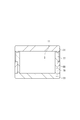
- FIG. 1 is an external view of an optical device according to an embodiment of the present invention.
- FIG. 2 is an external perspective view for explaining the lens and the waterproof elastic member according to the embodiment of the present invention.
- FIG. 3 is an exploded perspective view of the optical device shown in FIG. 4 is an exploded perspective view of the optical device shown in FIG. 1 from an angle different from that in FIG.
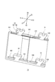
- FIG. 5 is a perspective view for explaining the shapes of the first accommodation case and the second accommodation case of the optical device shown in FIG. 6 is a cross-sectional view taken along the line AA shown in FIG. 7 is a cross-sectional view taken along the line BB shown in FIG.
- FIG. 8 is an external perspective view of the first housing case shown in FIG. 1 as viewed from the side coupled to the second housing case.
- FIG. 9 is an external perspective view of the second housing case shown in FIG. 1 as viewed from the side coupled to the first housing case.
- FIG. 1 is an external view of an optical device 1 according to an embodiment of the present invention
- FIG. 2 is an external perspective view for explaining a lens 11 and a waterproof elastic member 35 of the present embodiment
- FIG. 3 is an optical device shown in FIG. 4 is an exploded perspective view of the optical device 1 shown in FIG. 1 from an angle different from that of FIG. 3
- FIG. 5 is a perspective view of the first storage case 31 and the second storage case 33 of the optical device 1. It is a perspective view for demonstrating the shape of this. 6 is a cross-sectional view taken along the line AA shown in FIG. 1, and FIG. 7 is a cross-sectional view taken along the line BB shown in FIG.
- the optical device 1 includes, for example, a lens 11, a lens housing case 13, and a waterproof elastic member 35.
- the lens housing case 13 includes a first housing case 31 and a second housing case 33.
- the optical device 1 is fixedly mounted on a predetermined device or the like.
- the first housing case 31 and the second housing case 33 together form a lens housing space 11 a that houses the lens 11.
- the first engaging portion 51 provided in the first housing case 31 can be elastically bent and deformed in the thickness direction (X1-X2 direction) of the second housing case 33 and is orthogonal (crossed) to the thickness direction. ) Having a support portion 53 extending in the extending direction (Z1-Z2 direction) and a hook 55 positioned on the tip side thereof.
- the second engaging portion 71 provided in the second housing case 33 is formed as a recess toward the lens housing space 11 a on the outer surface of the second housing case 33.
- the second engagement portion 71 is a state in which the support portion receiving portion 73 for receiving the support portion 53, the hook receiving portion 75 for receiving (accommodating) the hook 55, and the support portion 53 are not bent and deformed in the thickness direction.
- the hook 55 accommodated in the hook receiving portion 75 has a first restricting portion 77 that restricts movement of the hook 55 outside in the Z1-Z2 direction.
- the outer surface of the first engagement portion 51 is the periphery of the second engagement portion 71 of the second housing case 33. It becomes the same as the outer surface of.
- the lens 11 has a substantially rectangular parallelepiped shape, and has a shape that is point-symmetric with respect to the central axis.
- a concave portion 11b closed along the outer periphery is formed on the outer periphery near the one end side of the lens 11, and the waterproof elastic member 35 is fitted into the concave portion 11b.
- the first storage case 31 has a first engagement portion 51 that engages with the second engagement portion 71 of the second storage case 33.
- the first engaging portion 51 extends in the Z2 direction.
- the first engaging portion 51 is fixedly coupled to the second engaging portion 71 so as to be detachable.
- the first housing case 31 has a total of four first engaging portions 51 at positions symmetrical with respect to both the central axis in the Y1-Y2 direction and the central axis in the X1-X2 direction.
- the first engaging portion 51 includes a support portion 53 and a hook 55.
- the support portion 53 is elastically bent in the thickness direction (X1-X2 direction) of the second housing case 33. It is deformable and extends in the extending direction (Z1-Z2 direction) orthogonal to (intersecting with) the thickness direction.
- the hook 55 is located on the distal end side in the extending direction (Z2 direction) with respect to the support portion 53.
- a hook portion (notch) 55a for moving the first engagement portion 51 in the thickness direction by hooking it with a finger or the like is provided at the end of the hook 55 of the first engagement portion 51 on the Z2 direction side.
- the outer surfaces of the formed support part 53 and hook 55 are flush with the outer surface of the second case.
- the second housing case 33 has second engaging portions 71 at four positions facing the four first engaging portions 51 described above, and the second engaging portions. 71 is engaged (fixedly coupled) with the first engaging portion 51.
- the second engagement portion 71 has an accommodation space for accommodating the first engagement portion 51.
- the second engaging portion 71 includes a support portion accommodating portion 73, a hook receiving portion 75, and a first restricting portion 77.
- the support part accommodation part 73 accommodates the support part 53 when the first accommodation case 31 and the second accommodation case 33 are fixedly coupled.
- the hook receiving portion 75 receives (accommodates) the hook 55 when the first accommodation case 31 and the second accommodation case 33 are fixedly coupled.
- the first restricting portion 77 is located adjacent to the hook receiving portion 75 in the supporting portion accommodating portion 73 side (Z1 direction side) and adjacent to the supporting portion accommodating portion 73 in the Y1 direction.
- the hook 55 accommodated in the hook receiving portion 75 is moved in the extending direction (Z1 direction) while the support portion 53 is not bent and deformed in the thickness direction (X1-X2 direction), that is, The movement in the direction away from the hook receiving portion 75 is restricted (becomes locked).
- the 1st control part 77 does not perform the control mentioned above, when the support part 53 carries out the said bending deformation to the predetermined
- the first restricting portion 77 is provided on the inner side in the thickness direction (X1-X2 direction) of the second housing case 33 and has a thickness smaller than that of the second housing case 33.
- the 2nd control part 79 which is is provided.
- the second restricting portion 79 restricts the movement of the hook 55 accommodated in the hook receiving portion 75 to the lens accommodating space 11a.
- the tip of the hook 55 is Engaging with the end of the restricting portion 77, the support portion 53 is bent and deformed in the thickness direction (X1-X2 direction), and the hook 55 moves to a position avoiding the restricting portion 77, and the hook 55 is moved to the hook receiving portion 75.
- the support portion 53 is deformed by the restoring force and becomes a shape before being deformed, and the hook 55 moves toward the second restricting portion 79. That is, the lock state is entered.
- FIG. 8 is an external perspective view of the first housing case 31 shown in FIG. 1 as viewed from the side coupled to the second housing case 33.
- the first storage case 31 includes third restriction portions 101, 103, 105, and 107 at a plurality of positions facing the second storage case 33.
- the third restricting portion 101 is located between the two first engaging portions 51 located along the Y1-Y2 direction, and has a tapered surface that inclines in the Z2 direction toward the outside in the X1-X2 direction. is doing.
- a third restricting portion 105 is formed on the Y2 side with respect to the third restricting portion 101.
- a third restricting portion 103 is formed in the vicinity of the Y2 side end portion of the first housing case 31. Further, a third restricting portion 107 is formed in the vicinity of the end portion in the Y1 direction with respect to the first engaging portion 51.
- the third restricting portions 103, 105, and 107 have a tapered surface that is inclined in the Z2 direction toward the center in the X1-X2 direction.
- FIG. 9 is an external perspective view of the second housing case 33 shown in FIG. 1 as viewed from the side coupled to the first housing case 31.
- the second storage case 33 includes fourth restriction portions 201, 203, 205, and 207 at a plurality of positions facing the first storage case 31.
- the fourth restricting portion 201 is located between the two second engaging portions 71 located along the Y1-Y2 direction, and has a tapered surface that inclines in the Z1 direction toward the center in the X1-X2 direction. is doing.
- the tapered surface of the fourth restricting portion 201 is surface-joined with the tapered surface of the third restricting portion 101.
- a fourth restricting portion 205 is formed on the Y2 side with respect to the fourth restricting portion 201.
- a fourth restricting portion 203 is formed in the vicinity of the Y2 side end portion of the second housing case 33.
- a fourth restricting portion 207 is formed in the vicinity of the end portion in the Y1 direction with respect to the second engaging portion 71.
- the fourth restricting portions 203, 205, and 207 have tapered surfaces that incline in the Z1 direction toward the outside in the X1-X2 direction. When the first housing case 31 and the second housing case 33 are coupled, the tapered surfaces of the fourth restricting portions 203, 205, and 207 are tapered surfaces of the third restricting portions 103, 105, and 107. And surface-join.
- the first housing case 31 is restricted from moving relative to the second housing case 33 in the X1 direction by the surface bonding of the tapered surface with the 201. Further, the taper surfaces of the third restricting portions 103.105, 107 and the fourth restricting portions 203, 205, 207 on the X2 direction side and the third restricting portion 101 on the X1 direction side and the fourth restricting surface are connected. The first housing case 31 is restricted from moving relative to the second housing case 33 in the X2 direction by surface bonding of the tapered surface with the restricting portion 201.
- the waterproof elastic member 35 is fitted into the recess 11 b near one end of the lens 11.
- the first housing case 31 and the second housing case 33 are moved closer to the Z1-Z2 direction with a part of the lens 11 including the portion to which the waterproof elastic member 35 is attached interposed therebetween.
- the first engaging portion 51 and the second engaging portion 71 are fixedly coupled.
- the tip of the hook 55 of the first engaging portion 51 of the first housing case 31 is the end of the restricting portion 77 of the second engaging portion 71 of the second housing case 33 on the Z1 direction side.
- the support portion 53 is bent and deformed outward in the thickness direction (X1-X2 direction). Due to the bending deformation of the support portion 53, the hook 55 moves to a position where the restricting portion 77 is avoided, and the hook 55 is accommodated in the hook receiving portion 75 while avoiding the restricting portion 77 of the second engaging portion 71.
- the support portion 53 becomes a shape before being deformed by the restoring force, and the hook 55 moves toward the second restricting portion 79. Retained. That is, the lock state is entered.
- the first engaging portion 51 and the second engaging portion 71 are fixedly coupled at four positions between the first housing case 31 and the second housing case 33, and the lens 11 is stabilized. It is held in the state.
- the taper surface is joined to the restricting portion 201.
- the first housing case 31 is restricted from moving relative to the second housing case 33 in the X2 direction. This restricts the hook 33 from coming off from the lens housing case 21 in the Y1 direction.
- the second engaging portion 71 is formed as a recess toward the lens housing space 11a on the outer surface of the second housing case 33, and the first
- the outer surface of the first engaging portion 51 is
- the second housing case 33 is configured to be flush with the outer surface around the second engagement portion 71. Therefore, the first storage case 31 and the second storage case 33 can be coupled with a relatively small shape. That is, the lens housing case 13 can be reduced in size.
- the hook 55 can be moved in a direction to be detached from the hook receiving portion 75 in the Z1-Z2 direction only when an external force is applied. Thereby, the 1st engagement part 51 and the 2nd engagement part 71 can be attached or detached.
- the first restricting portion 77 is provided inside the second housing case 33 in the thickness direction, and is thinner than the second housing case 33. Therefore, the second housing case 33 can be downsized by the first restricting portion 77.
- the hook 55 can be prevented from coming into contact with the lens 11 and being damaged.
- the second restricting portion 79 is provided between the lens housing space 11a and a part of the hook receiving portion 75, the area of the second restricting portion 79 that is thin in the thickness direction can be reduced. Can be easily done.
- the first accommodating case 31 is restricted from moving relative to the second accommodating case 33 in the X1 direction. it can. Further, the taper surfaces of the third restricting portions 103.105, 107 and the fourth restricting portions 203, 205, 207 on the X2 direction side and the third restricting portion 101 on the X1 direction side and the fourth restricting surface are connected.
- the present invention is not limited to the embodiment described above. That is, those skilled in the art may make various modifications, combinations, subcombinations, and alternatives regarding the components of the above-described embodiments within the technical scope of the present invention or an equivalent scope thereof.
- four combinations of the first engagement portion 51 and the second engagement portion 71 are provided to couple the first accommodation case 31 and the second accommodation case 33 together. Although illustrated, you may couple
- the lens 11 is exemplified as the optical component of the present invention, but a light guide path other than the lens may be used.
- first restricting portions 77 are formed at two locations around the hook receiving portion 75.
- the first engaging portion 51 may be provided as a separate body instead of being formed integrally with the first housing case 31.
- first restricting portion 77 and the second restricting portion 79 may be provided separately from the second housing case 33 instead of being integrated with the second housing case 33.
- the present invention can be applied to an optical component housing case such as an optical component lens.
Landscapes
- Engineering & Computer Science (AREA)
- Mechanical Engineering (AREA)
- Studio Devices (AREA)
Abstract
第1の収容ケース31に設けられた第1の係合部51は、厚み方向に弾性的に撓み変形可能であり当該厚み方向と直交する延出方向に延出した支持部53と、フック55とを有する。第2の収容ケース33の第2の係合部71は、支持部53を収容する支持部収容部73と、フック55を収容するフック受け部75と、支持部53が上記厚み方向に撓み変形していない状態で、フック受け部75に収容されたフック55がZ1方向に移動することを規制する第1の規制部77とを有する。
Description
本発明は、光学部品を固定して収容する光学部品収容ケースに関するものである。
電気機器等には、光源からの光の光路を形成するレンズ等の光学部品が搭載されることがある。
特許文献1には、蛍光板、拡散板、液晶パネルを上下2つのケース内に収容し、当該2つのケースをフックとフック受け穴で係合して固定する液晶表示装置が開示されている。
特許文献1には、蛍光板、拡散板、液晶パネルを上下2つのケース内に収容し、当該2つのケースをフックとフック受け穴で係合して固定する液晶表示装置が開示されている。
しかしながら、上記引用文献1の装置では、フックとフック受けとがケースの外側に突き出た形状で係合するため、2つのケースの側面が二重になり、ケースの厚み分だけ大きくなる。そのため、小型化が要求される製品には不利である。
本発明はかかる事情に鑑みてなされたものであり、その目的は、小型な構成で、光学部品を安定して収容可能な光学部品収容ケースを提供することにある。
上述した目的を達成するために、本発明の光学部品収容ケースは、光学部品を収容する光学部品収容ケースであって、一体となって前記光学部品を収容する収容空間を形成する第1の収容ケースおよび第2の収容ケースと、前記第1の収容ケースに設けられた第1の係合部と、前記第2の収容ケースに設けられ、前記第1の係合部と係合する第2の係合部とを有し、前記第1の係合部は、前記第2の収容ケースの厚み方向に弾性的に撓み変形可能であり前記厚み方向と交差する延出方向に延出した支持部と、前記支持部に対して前記延出方向の先端側に位置するフックとを有し、前記第2の係合部は、前記第2の収容ケースの外面に前記収容空間に向けた窪みとして形成され、前記支持部を収容する支持部収容部と、前記フックを受けるフック受け部と、前記フック受け部に対して前記支持部収容部側の一部に位置し、前記支持部が前記厚み方向に撓み変形していない状態で、前記延出方向の前記フック受け部から外れる方向に前記フックが移動することを規制する第1の規制部とを有し、前記第1の係合部と前記第2の係合部とを係合した状態で、前記第1の係合部の外面が、前記第2の収容ケースの前記第2の係合部の周辺の外面と面一となる。
この構成によれば、前記第2の収容ケースの外面に前記収容空間に向けた窪みとして前記第2の係合部を形成すると共に、前記第1の係合部と前記第2の係合部とを係合させて、前記第1の収容ケースと前記第2の収容ケースとを結合した場合に、前記第1の係合部の外面が、前記第2の収容ケースの前記第2の係合部の周辺の外面と面一となるように構成している。そのため、比較的小規模な形状で、前記第1の収容ケースと前記第2の収容ケースとを結合できる。すなわち、光学部品収容ケースの小型化を図れる。
好適には本発明の光学部品収容ケースの前記第1の規制部は、前記支持部が外力に応じて所定の形状に前記撓み変形している状態で、前記フックが前記延出方向の前記フック受け部から外れる方向に移動することを規制しない。
この構成によれば、外力を加えたときにのみ前記フックが前記延出方向の前記フック受け部から外れる方向に移動するようにできる。これにより、前記第1の係合部と前記第2の係合部との着脱が可能になる。
この構成によれば、外力を加えたときにのみ前記フックが前記延出方向の前記フック受け部から外れる方向に移動するようにできる。これにより、前記第1の係合部と前記第2の係合部との着脱が可能になる。
好適には本発明の光学部品収容ケースの前記第1の規制部は、前記第2の収容ケースの厚み方向の内側に設けられ、前記第2の収容ケースの厚みより薄い。
この構成によれば、前記第1の規制部によって、前記第2の収容ケースを小型化できる。
この構成によれば、前記第1の規制部によって、前記第2の収容ケースを小型化できる。
好適には本発明の光学部品収容ケースは、前記光学部品が収容される光学部品収容空間と前記フック受け部との間に前記フックの前記光学部品収容空間への移動を規制する第2の規制部を有する。
この構成によれば、前記フック受け部に収容された前記フックが前記光学部品に接触することを回避できる。
この構成によれば、前記フック受け部に収容された前記フックが前記光学部品に接触することを回避できる。
好適には本発明の光学部品収容ケースの記第2の規制部は、前記光学部品収容空間と、前記フック受け部の一部分との間に設けられている。
この構成によれば、厚み方向に薄い前記第2の規制部の面積を小さくでき、加工を容易にできる。
この構成によれば、厚み方向に薄い前記第2の規制部の面積を小さくでき、加工を容易にできる。
好適には本発明の光学部品収容ケースは、前記第1の係合部と前記第2の係合部とを前記延出方向に近づけて係合する過程で、前記支持部が前記厚み方向に前記撓み変形して前記フックが第1の規制部を回避して移動し、前記フックが前記フック受け部に収容されると前記支持部が復元力により前記撓み変形から変形前の形になる。
この構成によれば、前記支持部の撓み変形を利用した簡単な構造で、前記第1の係合部と前記第2の係合部とを結合できる。
この構成によれば、前記支持部の撓み変形を利用した簡単な構造で、前記第1の係合部と前記第2の係合部とを結合できる。
好適には本発明の光学部品収容ケースの前記第1の係合部には、当該第1の係合部を引っ掛けて前記厚み方向に移動させるための引っ掛け部が形成されている。
この構成によれば、簡単な構成で、前記第1の係合部と前記第2の係合部との結合を解除できる。
この構成によれば、簡単な構成で、前記第1の係合部と前記第2の係合部との結合を解除できる。
好適には本発明の光学部品収容ケースの前記第1の収容ケースは、前記第2の収容ケースに対向する異なる複数の位置のそれぞれに前記第1の係合部を有し、前記第2の収容ケースは、前記第1の収容ケースに対向する異なる複数の位置の各々に、前記第1の係合部と係合する前記第2の係合部を有する。
この構成によれば、前記第1の係合部と前記第2の係合部との組み合わせを複数設けることで、前記第1の収容ケースと前記第2の収容ケースとを安定して結合できる。
この構成によれば、前記第1の係合部と前記第2の係合部との組み合わせを複数設けることで、前記第1の収容ケースと前記第2の収容ケースとを安定して結合できる。
好適には本発明の光学部品収容ケースは、前記第1の収容ケースは、前記第2の収容ケースに対向する複数の位置に第3の規制部を有し、前記第2の収容ケースは、前記第1の収容ケースに対向する異なる複数の位置の各々に、前記第3の規制部と係合して前記第1の収容ケースと前記第2の収容ケースとの前記光学部品の光進行方向と直交する方向の相対的な移動方向を規制する前記第4の規制部を有し、一対の前記第3の規制部および前記第4の規制部が規制する前記移動方向と、他の一対の前記第3の規制部および前記第4の規制部が規制する前記移動方向とが反対方向である。
この構成によれば、前記光学部品の前記光進行方向と直交する方向における前記第1の収容ケースと前記第2の収容ケースとの相対的な移動を規制できる。
この構成によれば、前記光学部品の前記光進行方向と直交する方向における前記第1の収容ケースと前記第2の収容ケースとの相対的な移動を規制できる。
本発明によれば、小型な構成で、光学部品を安定して収容可能な光学部品収容体を提供することができる。
以下、本発明の実施形態に係る光学装置について説明する。
図1は本発明の実施形態に係る光学装置1の外観図、図2は本実施形態のレンズ11および防水用弾性部材35を説明するための外観斜視図、図3は図1に示す光学装置1の分解斜視図、図4は図1に示す光学装置1の図3とは異なる角度からの分解斜視図、図5は光学装置1の第1の収容ケース31と第2の収容ケース33との形状を説明するための斜視図である。
図6は図1に示すA-A断面図、図7は図1に示すB-B断面図である。
図1は本発明の実施形態に係る光学装置1の外観図、図2は本実施形態のレンズ11および防水用弾性部材35を説明するための外観斜視図、図3は図1に示す光学装置1の分解斜視図、図4は図1に示す光学装置1の図3とは異なる角度からの分解斜視図、図5は光学装置1の第1の収容ケース31と第2の収容ケース33との形状を説明するための斜視図である。
図6は図1に示すA-A断面図、図7は図1に示すB-B断面図である。
図1~図4に示すように、本発明の実施形態の光学装置1は、例えば、レンズ11、レンズ収容ケース13、および防水用弾性部材35を有する。
レンズ収容ケース13は、第1の収容ケース31および第2の収容ケース33を有する。
光学装置1は、所定の機器などに固定して搭載される。
レンズ収容ケース13は、第1の収容ケース31および第2の収容ケース33を有する。
光学装置1は、所定の機器などに固定して搭載される。
第1の収容ケース31および第2の収容ケース33は、一体となってレンズ11を収容するレンズ収容空間11aを形成する。
第1の収容ケース31に設けられた第1の係合部51は、第2の収容ケース33の厚み方向(X1-X2方向)に弾性的に撓み変形可能であり当該厚み方向と直交(交差)する延出方向(Z1-Z2方向)に延出した支持部53と、その先端側に位置するフック55とを有する。
第1の収容ケース31に設けられた第1の係合部51は、第2の収容ケース33の厚み方向(X1-X2方向)に弾性的に撓み変形可能であり当該厚み方向と直交(交差)する延出方向(Z1-Z2方向)に延出した支持部53と、その先端側に位置するフック55とを有する。
第2の収容ケース33に設けられた第2の係合部71は、第2の収容ケース33の外面にレンズ収容空間11aに向けた窪みとして形成されている。
第2の係合部71は、支持部53を収容する支持部収容部73と、フック55を受ける(収容する)フック受け部75と、支持部53が上記厚み方向に撓み変形していない状態で、フック受け部75に収容されたフック55がZ1-Z2方向の外側に移動することを規制する第1の規制部77とを有する。
第1の係合部51と第2の係合部71とを係合した状態で、第1の係合部51の外面が、第2の収容ケース33の第2の係合部71の周辺の外面と面一となる。
第2の係合部71は、支持部53を収容する支持部収容部73と、フック55を受ける(収容する)フック受け部75と、支持部53が上記厚み方向に撓み変形していない状態で、フック受け部75に収容されたフック55がZ1-Z2方向の外側に移動することを規制する第1の規制部77とを有する。
第1の係合部51と第2の係合部71とを係合した状態で、第1の係合部51の外面が、第2の収容ケース33の第2の係合部71の周辺の外面と面一となる。
[レンズ11]
図2に示すように、レンズ11は、略直方体形状をしており、中心軸に対して点対称となる形状を有している。
レンズ11の一端側付近の外周には、外周に沿って閉じた凹部11bが形成されており、凹部11bに防水用弾性部材35が嵌め込まれる。
図2に示すように、レンズ11は、略直方体形状をしており、中心軸に対して点対称となる形状を有している。
レンズ11の一端側付近の外周には、外周に沿って閉じた凹部11bが形成されており、凹部11bに防水用弾性部材35が嵌め込まれる。
[第1の収容ケース31]
第1の収容ケース31は、第2の収容ケース33の第2の係合部71と係合する第1の係合部51を有する。第1の係合部51は、Z2方向に延出している。第1の係合部51は、第2の係合部71と着脱可能に固定結合する。
第1の収容ケース31は、Y1-Y2方向の中心軸と、X1―X2方向の中心軸の双方に線対称となる位置に合計4つの第1の係合部51を有する。
第1の収容ケース31は、第2の収容ケース33の第2の係合部71と係合する第1の係合部51を有する。第1の係合部51は、Z2方向に延出している。第1の係合部51は、第2の係合部71と着脱可能に固定結合する。
第1の収容ケース31は、Y1-Y2方向の中心軸と、X1―X2方向の中心軸の双方に線対称となる位置に合計4つの第1の係合部51を有する。
図3に示すように、第1の係合部51は、支持部53とフック55とを有する
支持部53は、第2の収容ケース33の厚み方向(X1-X2方向)に弾性的に撓み変形可能であり、当該厚み方向と直交(交差)する延出方向(Z1-Z2方向)に延出している。
フック55は、支持部53に対して延出方向(Z2方向)の先端側に位置する。
また、第1の係合部51のフック55のZ2方向側端部には、指等で引っ掛けて第1の係合部51を上記厚み方向に移動させるための引っ掛け部(切り欠き)55aが形成されている
支持部53およびフック55の外面と、前記第2のケースの外面とは面一である。
支持部53は、第2の収容ケース33の厚み方向(X1-X2方向)に弾性的に撓み変形可能であり、当該厚み方向と直交(交差)する延出方向(Z1-Z2方向)に延出している。
フック55は、支持部53に対して延出方向(Z2方向)の先端側に位置する。
また、第1の係合部51のフック55のZ2方向側端部には、指等で引っ掛けて第1の係合部51を上記厚み方向に移動させるための引っ掛け部(切り欠き)55aが形成されている
支持部53およびフック55の外面と、前記第2のケースの外面とは面一である。
[第2の収容ケース33]
図2に示すように、第2の収容ケース33は、上述した4つの第1の係合部51と対向する4か所に第2の係合部71を有し、第2の係合部71が第1の係合部51と係合(固定結合)する。
第2の係合部71は、第1の係合部51を収容する収容空間を有する。
図2に示すように、第2の収容ケース33は、上述した4つの第1の係合部51と対向する4か所に第2の係合部71を有し、第2の係合部71が第1の係合部51と係合(固定結合)する。
第2の係合部71は、第1の係合部51を収容する収容空間を有する。
図3に示すように、第2の係合部71は、支持部収容部73、フック受け部75および第1の規制部77を有する。
支持部収容部73は、第1の収容ケース31と第2の収容ケース33との固定結合時に支持部53を収容する。
フック受け部75は、第1の収容ケース31と第2の収容ケース33との固定結合時にフック55を受ける(収容)する。
支持部収容部73は、第1の収容ケース31と第2の収容ケース33との固定結合時に支持部53を収容する。
フック受け部75は、第1の収容ケース31と第2の収容ケース33との固定結合時にフック55を受ける(収容)する。
第1の規制部77は、フック受け部75に対して支持部収容部73側(Z1方向側)、且つ支持部収容部73に対してY1方向に隣接して位置する。
第1の規制部77は、支持部53が厚み方向(X1-X2方向)に撓み変形していない状態でフック受け部75に収容されたフック55が延出方向(Z1方向)の移動、すなわちフック受け部75から外れる方向の移動を規制する(ロック状態になる)。
第1の規制部77は、支持部53が厚み方向(X1-X2方向)に撓み変形していない状態でフック受け部75に収容されたフック55が延出方向(Z1方向)の移動、すなわちフック受け部75から外れる方向の移動を規制する(ロック状態になる)。
また、第1の規制部77は、支持部53が所定の形状に上記撓み変形した場合に上述した規制をしない(非ロック状態になる)。
第1の規制部77は、第2の収容ケース33の厚み方向(X1-X2方向)の内側に設けられ、第2の収容ケース33より薄い厚みを有している。
第1の規制部77は、第2の収容ケース33の厚み方向(X1-X2方向)の内側に設けられ、第2の収容ケース33より薄い厚みを有している。
フック55を受けるフック受け部75内の第1の規制部77に対してZ2方向側には、レンズ11を収容するレンズ収容空間11aとの間に規制部77と一体となって形成された壁である第2の規制部79が設けられている。
第2の規制部79は、フック受け部75に収容されたフック55のレンズ収容空間11aへの移動を規制する。
第2の規制部79は、フック受け部75に収容されたフック55のレンズ収容空間11aへの移動を規制する。
第1の収容ケース31と第2の収容ケース33とをZ1-Z2方向に近づけて第1の係合部51と第2の係合部71とを固定結合する過程で、フック55の先端が規制部77の端部と係合して支持部53が厚み方向(X1-X2方向)に撓み変形してフック55が規制部77を回避する位置に移動し、フック55がフック受け部75に収容されると支持部53が復元力によって撓み変形前の形状になり、フック55が第2の規制部79に向けて移動する。すなわちロック状態になる。
図8は図1に示す第1の収容ケース31の第2の収容ケース33と結合する側から見た外観斜視図である。
第1の収容ケース31は、第2の収容ケース33に対向する複数の位置に第3の規制部101,103,105,107を有する。
第3の規制部101は、Y1-Y2方向に沿って位置する2つの第1の係合部51の間に位置し、X1-X2方向の外側に向かうに従ってZ2方向に傾斜するテーパ面を有している。
第1の収容ケース31は、第2の収容ケース33に対向する複数の位置に第3の規制部101,103,105,107を有する。
第3の規制部101は、Y1-Y2方向に沿って位置する2つの第1の係合部51の間に位置し、X1-X2方向の外側に向かうに従ってZ2方向に傾斜するテーパ面を有している。
第3の規制部101に対してY2側には、第3の規制部105が形成されている。また、第1の収容ケース31のY2側の端部付近には第3の規制部103が形成されている。
また、第1の係合部51に対してY1方向端部付近には第3の規制部107が形成されている。
第3の規制部103,105,107は、X1-X2方向の中央に向かうに従ってZ2方向に傾斜するテーパ面を有している。
また、第1の係合部51に対してY1方向端部付近には第3の規制部107が形成されている。
第3の規制部103,105,107は、X1-X2方向の中央に向かうに従ってZ2方向に傾斜するテーパ面を有している。
図9は図1に示す第2の収容ケース33の第1の収容ケース31と結合する側から見た外観斜視図である。
第2の収容ケース33は、第1の収容ケース31に対向する複数の位置に第4の規制部201,203,205,207を有する。
第4の規制部201は、Y1-Y2方向に沿って位置する2つの第2の係合部71の間に位置し、X1-X2方向の中央に向かうに従ってZ1方向に傾斜するテーパ面を有している。
第1の収容ケース31と第2の収容ケース33とを結合している場合に、第4の規制部201のテーパ面は、第3の規制部101のテーパ面と面接合する。
第2の収容ケース33は、第1の収容ケース31に対向する複数の位置に第4の規制部201,203,205,207を有する。
第4の規制部201は、Y1-Y2方向に沿って位置する2つの第2の係合部71の間に位置し、X1-X2方向の中央に向かうに従ってZ1方向に傾斜するテーパ面を有している。
第1の収容ケース31と第2の収容ケース33とを結合している場合に、第4の規制部201のテーパ面は、第3の規制部101のテーパ面と面接合する。
第4の規制部201に対してY2側には、第4の規制部205が形成されている。また、第2の収容ケース33のY2側の端部付近には第4の規制部203が形成されている。
また、第2の係合部71に対してY1方向端部付近には第4の規制部207が形成されている。
第4の規制部203,205,207は、X1-X2方向の外側に向かうに従ってZ1方向に傾斜するテーパ面を有している。
第1の収容ケース31と第2の収容ケース33とを結合している場合に、第4の規制部203,205,207のテーパ面は、第3の規制部103,105,107のテーパ面と面接合する。
また、第2の係合部71に対してY1方向端部付近には第4の規制部207が形成されている。
第4の規制部203,205,207は、X1-X2方向の外側に向かうに従ってZ1方向に傾斜するテーパ面を有している。
第1の収容ケース31と第2の収容ケース33とを結合している場合に、第4の規制部203,205,207のテーパ面は、第3の規制部103,105,107のテーパ面と面接合する。
X1方向側の第3の規制部103.105,107と第4の規制部203,205,207とのテーパ面の面接合、並びにX2方向側の第3の規制部101と第4の規制部201とのテーパ面の面接合によって、第1の収容ケース31が第2の収容ケース33に対してX1方向に相対的に移動することが規制される。
また、X2方向側の第3の規制部103.105,107と第4の規制部203,205,207とのテーパ面の面接合、並びにX1方向側の第3の規制部101と第4の規制部201とのテーパ面の面接合によって、第1の収容ケース31が第2の収容ケース33に対してX2方向に相対的に移動することが規制される。
また、X2方向側の第3の規制部103.105,107と第4の規制部203,205,207とのテーパ面の面接合、並びにX1方向側の第3の規制部101と第4の規制部201とのテーパ面の面接合によって、第1の収容ケース31が第2の収容ケース33に対してX2方向に相対的に移動することが規制される。
以下、レンズ11の組み立て方法について説明する。
図2に示すように、レンズ11の一端側付近の凹部11bに防水用弾性部材35が嵌め込む。
図3に示すように、防水用弾性部材35を装着した部分を含むレンズ11の一部を間に挟んで第1の収容ケース31と第2の収容ケース33とをZ1-Z2方向に近づけて第1の係合部51と第2の係合部71とを固定結合する。
図2に示すように、レンズ11の一端側付近の凹部11bに防水用弾性部材35が嵌め込む。
図3に示すように、防水用弾性部材35を装着した部分を含むレンズ11の一部を間に挟んで第1の収容ケース31と第2の収容ケース33とをZ1-Z2方向に近づけて第1の係合部51と第2の係合部71とを固定結合する。
この過程で、第1の収容ケース31の第1の係合部51のフック55の先端が、第2の収容ケース33の第2の係合部71の規制部77のZ1方向側の端部と係合して支持部53が厚み方向(X1-X2方向)の外側に撓み変形する。
当該支持部53の撓み変形により、フック55が規制部77を回避する位置に移動し、フック55が第2の係合部71の規制部77を回避してフック受け部75に収容される。
当該支持部53の撓み変形により、フック55が規制部77を回避する位置に移動し、フック55が第2の係合部71の規制部77を回避してフック受け部75に収容される。
そして、フック55がフック受け部75の位置にくると、支持部53が復元力によって撓み変形前の形状になり、フック55が第2の規制部79に向けて移動し、フック受け部75内に保持される。すなわちロック状態になる。これにより、第1の収容ケース31と第2の収容ケース33との間の4か所において、第1の係合部51と第2の係合部71とが固定結合し、レンズ11が安定した状態で保持される。
また、上述した第1の係合部51と第2の係合部71とが係合する過程で、X1方向側の第3の規制部103.105,107と第4の規制部203,205,207とのテーパ面の面接合、並びにX2方向側の第3の規制部101と第4の規制部201とのテーパ面の面接合する。これによって、第1の収容ケース31が第2の収容ケース33に対してX1方向に相対的に移動することが規制される。
それと同時に、X2方向側の第3の規制部103.105,107と第4の規制部203,205,207とのテーパ面の面接合、並びにX1方向側の第3の規制部101と第4の規制部201とのテーパ面の面接合する。これによって、第1の収容ケース31が第2の収容ケース33に対してX2方向に相対的に移動することが規制される。
これにより、フック33がレンズ収容ケース21からY1方向に外れることが規制される。
それと同時に、X2方向側の第3の規制部103.105,107と第4の規制部203,205,207とのテーパ面の面接合、並びにX1方向側の第3の規制部101と第4の規制部201とのテーパ面の面接合する。これによって、第1の収容ケース31が第2の収容ケース33に対してX2方向に相対的に移動することが規制される。
これにより、フック33がレンズ収容ケース21からY1方向に外れることが規制される。
以上説明したように、本実施形態のレンズ収容ケース13によれば、第2の収容ケース33の外面にレンズ収容空間11aに向けた窪みとして第2の係合部71を形成すると共に、第1の係合部51と第2の係合部71とを係合させて、第1の収容ケース31と第2の収容ケース33とを結合した場合に、第1の係合部51の外面が、第2の収容ケース33の第2の係合部71の周辺の外面と面一となるように構成している。そのため、比較的小規模な形状で、第1の収容ケース31と第2の収容ケース33とを結合できる。すなわち、レンズ収容ケース13の小型化を図れる。
また、レンズ収容ケース13によれば、外力を加えたときにのみフック55がZ1-Z2方向のフック受け部75から外れる方向に移動するようにできる。これにより、第1の係合部51と第2の係合部71との着脱が可能になる。
また、レンズ収容ケース13では、第1の規制部77は、第2の収容ケース33の厚み方向の内側に設けられ、第2の収容ケース33の厚みより薄い。そのため、第1の規制部77によって、第2の収容ケース33を小型化できる。
また、レンズ収容ケース13では、レンズ収容空間11aとフック受け部75との間に第2の規制部79を設けたことで、フック55がレンズ11に接触して傷を付けることを回避できる。
また、第2の規制部79は、レンズ収容空間11aと、フック受け部75の一部との間に設けられているため、厚み方向に薄い第2の規制部79の面積を小さくでき、加工を容易にできる。
また、レンズ収容ケース13では、上述したように、X1方向側の第3の規制部103.105,107と第4の規制部203,205,207とのテーパ面の面接合、並びにX2方向側の第3の規制部101と第4の規制部201とのテーパ面の面接合によって、第1の収容ケース31が第2の収容ケース33に対してX1方向に相対的に移動することを規制できる。また、X2方向側の第3の規制部103.105,107と第4の規制部203,205,207とのテーパ面の面接合、並びにX1方向側の第3の規制部101と第4の規制部201とのテーパ面の面接合によって、第1の収容ケース31が第2の収容ケース33に対してX2方向に相対的に移動することを規制できる。これにより、第1の収容ケース31と第2の収容ケース33とを安定して結合できる。
本発明は上述した実施形態には限定されない。
すなわち、当業者は、本発明の技術的範囲またはその均等の範囲内において、上述した実施形態の構成要素に関し、様々な変更、コンビネーション、サブコンビネーション、並びに代替を行ってもよい。
例えば、上述した実施形態では、第1の係合部51と第2の係合部71との組み合わせを4か所設けて、第1の収容ケース31と第2の収容ケース33とを結合する例示したが、1,2か所あるいは5か所以上で結合してもよい。
すなわち、当業者は、本発明の技術的範囲またはその均等の範囲内において、上述した実施形態の構成要素に関し、様々な変更、コンビネーション、サブコンビネーション、並びに代替を行ってもよい。
例えば、上述した実施形態では、第1の係合部51と第2の係合部71との組み合わせを4か所設けて、第1の収容ケース31と第2の収容ケース33とを結合する例示したが、1,2か所あるいは5か所以上で結合してもよい。
上述した実施形態では、本発明の光学部品としてレンズ11を例示したが、レンズ以外の導光路であってもよい。
また、上述した実施形態では、フック受け部75がL字に形成された場合を例示したが、T字形成してもよい。この場合は、フック受け部75の周囲の2か所に第1の規制部77が形成される。
また、第1の係合部51は、第1の収容ケース31と一体として形成するのではなく、別体として設けてもよい。
また、第1の規制部77および第2の規制部79は、第2の収容ケース33と一体ではなく、別体として設けてもよい。
また、第1の係合部51は、第1の収容ケース31と一体として形成するのではなく、別体として設けてもよい。
また、第1の規制部77および第2の規制部79は、第2の収容ケース33と一体ではなく、別体として設けてもよい。
本発明は光学部品のレンズ等の光学部品収容ケースに適用可能である。
1…光学装置
11…レンズ
11a…レンズ収容空間
11b…凹部
31…第1の収容ケース
51…第1の係合部
53…支持部
55…フック
55a…引っ掛け部(切り欠き)
33…第2の収容ケース
71…第2の係合部
73…支持部収容部
75…フック受け部
77…第1の規制部
79…第2の規制部
101,103.105,107…第3の規制部
201,203.205,207…第4の規制部
11…レンズ
11a…レンズ収容空間
11b…凹部
31…第1の収容ケース
51…第1の係合部
53…支持部
55…フック
55a…引っ掛け部(切り欠き)
33…第2の収容ケース
71…第2の係合部
73…支持部収容部
75…フック受け部
77…第1の規制部
79…第2の規制部
101,103.105,107…第3の規制部
201,203.205,207…第4の規制部
Claims (9)
- 光学部品を収容する光学部品収容ケースであって、
一体となって前記光学部品を収容する収容空間を形成する第1の収容ケースおよび第2の収容ケースと、
前記第1の収容ケースに設けられた第1の係合部と、
前記第2の収容ケースに設けられ、前記第1の係合部と係合する第2の係合部と
を有し、
前記第1の係合部は、
前記第2の収容ケースの厚み方向に弾性的に撓み変形可能であり前記厚み方向と交差する延出方向に延出した支持部と、前記支持部に対して前記延出方向の先端側に位置するフックとを有し、
前記第2の係合部は、
前記第2の収容ケースの外面に前記収容空間に向けた窪みとして形成され、
前記支持部を収容する支持部収容部と、
前記フックを受けるフック受け部と、
前記フック受け部に対して前記支持部収容部側の一部に位置し、前記支持部が前記厚み方向に撓み変形していない状態で、前記延出方向の前記フック受け部から外れる方向に前記フックが移動することを規制する第1の規制部と
を有し、
前記第1の係合部と前記第2の係合部とを係合した状態で、前記第1の係合部の外面が、前記第2の収容ケースの前記第2の係合部の周辺の外面と面一となる
光学部品収容ケース。 - 前記第1の規制部は、前記支持部が外力に応じて所定の形状に前記撓み変形している状態で、前記フックが前記延出方向の前記フック受け部から外れる方向に移動することを規制しない
請求項1に記載の光学部品収容ケース。 - 前記第1の規制部は、前記第2の収容ケースの厚み方向の内側に設けられ、前記第2の収容ケースの厚みより薄い
請求項1又は請求項2に記載の光学部品収容ケース。 - 前記光学部品が収容される光学部品収容空間と前記フック受け部との間に前記フックの前記光学部品収容空間への移動を規制する第2の規制部を有する
請求項1~3のいずれかに記載の光学部品収容ケース。 - 前記第2の規制部は、前記光学部品収容空間と、前記フック受け部の一部分との間に設けられている
請求項4に記載の光学部品収容ケース。 - 前記第1の係合部と前記第2の係合部とを前記延出方向に近づけて係合する過程で、前記支持部が前記厚み方向に前記撓み変形して前記フックが第1の規制部を回避して移動し、前記フックが前記フック受け部に収容されると前記支持部が復元力により前記撓み変形から変形前の形になる
請求項1~5のいずれかに記載の光学部品収容ケース。 - 前記第1の係合部には、当該第1の係合部を引っ掛けて前記厚み方向に移動させるための引っ掛け部が形成されている
請求項1~6のいずれかに記載の光学部品収容ケース。 - 前記第1の収容ケースは、前記第2の収容ケースに対向する異なる複数の位置のそれぞれに前記第1の係合部を有し、
前記第2の収容ケースは、前記第1の収容ケースに対向する異なる複数の位置の各々に、前記第1の係合部と係合する前記第2の係合部を有する
請求項1~7のいずれかに記載の光学部品収容ケース。 - 前記第1の収容ケースは、前記第2の収容ケースに対向する複数の位置に第3の規制部を有し、
前記第2の収容ケースは、前記第1の収容ケースに対向する異なる複数の位置の各々に、前記第3の規制部と係合して前記第1の収容ケースと前記第2の収容ケースとの前記光学部品の光進行方向と直交する方向の相対的な移動方向を規制する前記第4の規制部を有し、
一対の前記第3の規制部および前記第4の規制部が規制する前記移動方向と、他の一対の前記第3の規制部および前記第4の規制部が規制する前記移動方向とが反対方向である
請求項1~8のいずれかに記載の光学部品収容ケース。
Applications Claiming Priority (2)
| Application Number | Priority Date | Filing Date | Title |
|---|---|---|---|
| JP2016-047438 | 2016-03-10 | ||
| JP2016047438 | 2016-03-10 |
Publications (1)
| Publication Number | Publication Date |
|---|---|
| WO2017154483A1 true WO2017154483A1 (ja) | 2017-09-14 |
Family
ID=59790391
Family Applications (1)
| Application Number | Title | Priority Date | Filing Date |
|---|---|---|---|
| PCT/JP2017/005300 Ceased WO2017154483A1 (ja) | 2016-03-10 | 2017-02-14 | 光学部品収容ケース |
Country Status (1)
| Country | Link |
|---|---|
| WO (1) | WO2017154483A1 (ja) |
Citations (4)
| Publication number | Priority date | Publication date | Assignee | Title |
|---|---|---|---|---|
| JPS5634610Y2 (ja) * | 1977-07-11 | 1981-08-15 | ||
| JPS5827959Y2 (ja) * | 1976-12-15 | 1983-06-17 | 松下電工株式会社 | ケ−ス |
| JPS61107753U (ja) * | 1984-12-21 | 1986-07-08 | ||
| JP2013173549A (ja) * | 2012-02-24 | 2013-09-05 | Konica Minolta Inc | レンズ収納ケース |
-
2017
- 2017-02-14 WO PCT/JP2017/005300 patent/WO2017154483A1/ja not_active Ceased
Patent Citations (4)
| Publication number | Priority date | Publication date | Assignee | Title |
|---|---|---|---|---|
| JPS5827959Y2 (ja) * | 1976-12-15 | 1983-06-17 | 松下電工株式会社 | ケ−ス |
| JPS5634610Y2 (ja) * | 1977-07-11 | 1981-08-15 | ||
| JPS61107753U (ja) * | 1984-12-21 | 1986-07-08 | ||
| JP2013173549A (ja) * | 2012-02-24 | 2013-09-05 | Konica Minolta Inc | レンズ収納ケース |
Similar Documents
| Publication | Publication Date | Title |
|---|---|---|
| CN115061257B (zh) | 镜头驱动装置、照相机模块和移动电话 | |
| CN117572657A (zh) | 用于光学防抖的反射模块和包括该反射模块的相机模块 | |
| JP6691001B2 (ja) | 振れ補正機能付き光学ユニット | |
| JP2012251803A (ja) | モジュールおよび電子機器 | |
| KR20120122466A (ko) | 카메라 모듈 | |
| KR20160073763A (ko) | 렌즈 구동 장치 | |
| KR20240161620A (ko) | 렌즈 구동 장치 및 이를 포함하는 카메라 모듈 | |
| CN111258148A (zh) | 光学单元 | |
| KR20200119031A (ko) | 회전 카메라를 포함하는 전자장치 | |
| JP2021032930A (ja) | 振れ補正機能付き光学ユニット | |
| JP2020160373A (ja) | 振れ補正機能付き光学ユニット | |
| US20210373615A1 (en) | Electronic device including connector to which accessory device is attachable | |
| JP6403089B2 (ja) | 基板接続構造および電子機器 | |
| KR102837211B1 (ko) | 카메라 모듈 및 이를 포함하는 전자 장치 | |
| CN111284414B (zh) | 检测装置 | |
| JP2013004617A (ja) | 筐体部品 | |
| WO2017154483A1 (ja) | 光学部品収容ケース | |
| KR20170104837A (ko) | 이동 단말기 | |
| US20140177143A1 (en) | Electronic apparatus | |
| JP2022545600A (ja) | エッチングされた光学組立体ハウジング | |
| US20120113350A1 (en) | Back frame and display device having the same | |
| CN114217402A (zh) | 光学部件驱动装置、照相机装置以及电子设备 | |
| JP7076489B2 (ja) | 駆動装置、カメラ装置及び電子機器 | |
| WO2022000549A1 (zh) | 镜头驱动装置 | |
| JP4450041B2 (ja) | ラベル取付構造及び薄型モニタ装置 |
Legal Events
| Date | Code | Title | Description |
|---|---|---|---|
| NENP | Non-entry into the national phase |
Ref country code: DE |
|
| 121 | Ep: the epo has been informed by wipo that ep was designated in this application |
Ref document number: 17762826 Country of ref document: EP Kind code of ref document: A1 |
|
| 122 | Ep: pct application non-entry in european phase |
Ref document number: 17762826 Country of ref document: EP Kind code of ref document: A1 |
|
| NENP | Non-entry into the national phase |
Ref country code: JP |