WO2017150207A1 - Magnetic measuring device - Google Patents
Magnetic measuring device Download PDFInfo
- Publication number
- WO2017150207A1 WO2017150207A1 PCT/JP2017/005824 JP2017005824W WO2017150207A1 WO 2017150207 A1 WO2017150207 A1 WO 2017150207A1 JP 2017005824 W JP2017005824 W JP 2017005824W WO 2017150207 A1 WO2017150207 A1 WO 2017150207A1
- Authority
- WO
- WIPO (PCT)
- Prior art keywords
- sensor
- magnetic
- respect
- inclination angle
- degrees
- Prior art date
Links
Images


Classifications
-
- A—HUMAN NECESSITIES
- A61—MEDICAL OR VETERINARY SCIENCE; HYGIENE
- A61B—DIAGNOSIS; SURGERY; IDENTIFICATION
- A61B5/00—Measuring for diagnostic purposes; Identification of persons
- A61B5/24—Detecting, measuring or recording bioelectric or biomagnetic signals of the body or parts thereof
- A61B5/242—Detecting biomagnetic fields, e.g. magnetic fields produced by bioelectric currents
-
- A—HUMAN NECESSITIES
- A61—MEDICAL OR VETERINARY SCIENCE; HYGIENE
- A61B—DIAGNOSIS; SURGERY; IDENTIFICATION
- A61B5/00—Measuring for diagnostic purposes; Identification of persons
- A61B5/0033—Features or image-related aspects of imaging apparatus classified in A61B5/00, e.g. for MRI, optical tomography or impedance tomography apparatus; arrangements of imaging apparatus in a room
- A61B5/0035—Features or image-related aspects of imaging apparatus classified in A61B5/00, e.g. for MRI, optical tomography or impedance tomography apparatus; arrangements of imaging apparatus in a room adapted for acquisition of images from more than one imaging mode, e.g. combining MRI and optical tomography
-
- A—HUMAN NECESSITIES
- A61—MEDICAL OR VETERINARY SCIENCE; HYGIENE
- A61B—DIAGNOSIS; SURGERY; IDENTIFICATION
- A61B5/00—Measuring for diagnostic purposes; Identification of persons
- A61B5/05—Detecting, measuring or recording for diagnosis by means of electric currents or magnetic fields; Measuring using microwaves or radio waves
-
- A—HUMAN NECESSITIES
- A61—MEDICAL OR VETERINARY SCIENCE; HYGIENE
- A61B—DIAGNOSIS; SURGERY; IDENTIFICATION
- A61B5/00—Measuring for diagnostic purposes; Identification of persons
- A61B5/40—Detecting, measuring or recording for evaluating the nervous system
- A61B5/4029—Detecting, measuring or recording for evaluating the nervous system for evaluating the peripheral nervous systems
- A61B5/4041—Evaluating nerves condition
-
- A—HUMAN NECESSITIES
- A61—MEDICAL OR VETERINARY SCIENCE; HYGIENE
- A61B—DIAGNOSIS; SURGERY; IDENTIFICATION
- A61B5/00—Measuring for diagnostic purposes; Identification of persons
- A61B5/70—Means for positioning the patient in relation to the detecting, measuring or recording means
- A61B5/704—Tables
-
- A—HUMAN NECESSITIES
- A61—MEDICAL OR VETERINARY SCIENCE; HYGIENE
- A61B—DIAGNOSIS; SURGERY; IDENTIFICATION
- A61B6/00—Apparatus for radiation diagnosis, e.g. combined with radiation therapy equipment
- A61B6/04—Positioning of patients; Tiltable beds or the like
- A61B6/0407—Supports, e.g. tables or beds, for the body or parts of the body
- A61B6/045—Supports, e.g. tables or beds, for the body or parts of the body with heating or cooling means
-
- A—HUMAN NECESSITIES
- A61—MEDICAL OR VETERINARY SCIENCE; HYGIENE
- A61B—DIAGNOSIS; SURGERY; IDENTIFICATION
- A61B6/00—Apparatus for radiation diagnosis, e.g. combined with radiation therapy equipment
- A61B6/52—Devices using data or image processing specially adapted for radiation diagnosis
- A61B6/5211—Devices using data or image processing specially adapted for radiation diagnosis involving processing of medical diagnostic data
- A61B6/5229—Devices using data or image processing specially adapted for radiation diagnosis involving processing of medical diagnostic data combining image data of a patient, e.g. combining a functional image with an anatomical image
- A61B6/5247—Devices using data or image processing specially adapted for radiation diagnosis involving processing of medical diagnostic data combining image data of a patient, e.g. combining a functional image with an anatomical image combining images from an ionising-radiation diagnostic technique and a non-ionising radiation diagnostic technique, e.g. X-ray and ultrasound
-
- G—PHYSICS
- G01—MEASURING; TESTING
- G01R—MEASURING ELECTRIC VARIABLES; MEASURING MAGNETIC VARIABLES
- G01R33/00—Arrangements or instruments for measuring magnetic variables
- G01R33/007—Environmental aspects, e.g. temperature variations, radiation, stray fields
- G01R33/0082—Compensation, e.g. compensating for temperature changes
-
- G—PHYSICS
- G01—MEASURING; TESTING
- G01R—MEASURING ELECTRIC VARIABLES; MEASURING MAGNETIC VARIABLES
- G01R33/00—Arrangements or instruments for measuring magnetic variables
- G01R33/02—Measuring direction or magnitude of magnetic fields or magnetic flux
- G01R33/035—Measuring direction or magnitude of magnetic fields or magnetic flux using superconductive devices
-
- A—HUMAN NECESSITIES
- A61—MEDICAL OR VETERINARY SCIENCE; HYGIENE
- A61B—DIAGNOSIS; SURGERY; IDENTIFICATION
- A61B2562/00—Details of sensors; Constructional details of sensor housings or probes; Accessories for sensors
- A61B2562/02—Details of sensors specially adapted for in-vivo measurements
- A61B2562/0223—Magnetic field sensors
-
- A—HUMAN NECESSITIES
- A61—MEDICAL OR VETERINARY SCIENCE; HYGIENE
- A61B—DIAGNOSIS; SURGERY; IDENTIFICATION
- A61B2562/00—Details of sensors; Constructional details of sensor housings or probes; Accessories for sensors
- A61B2562/16—Details of sensor housings or probes; Details of structural supports for sensors
- A61B2562/164—Details of sensor housings or probes; Details of structural supports for sensors the sensor is mounted in or on a conformable substrate or carrier
-
- A—HUMAN NECESSITIES
- A61—MEDICAL OR VETERINARY SCIENCE; HYGIENE
- A61N—ELECTROTHERAPY; MAGNETOTHERAPY; RADIATION THERAPY; ULTRASOUND THERAPY
- A61N1/00—Electrotherapy; Circuits therefor
- A61N1/02—Details
- A61N1/04—Electrodes
- A61N1/0404—Electrodes for external use
- A61N1/0408—Use-related aspects
- A61N1/0456—Specially adapted for transcutaneous electrical nerve stimulation [TENS]
Definitions
- the present invention relates to a magnetic measuring device.
- the tip surface of the sensor cylinder is applied to a living body, and biomagnetism is measured by a magnetic sensor housed inside the sensor cylinder. At this time, the measurement is repeated while moving the subject with respect to the sensor tube.
- the elderly lose the mobility of the spine due to aging, and cannot freely bend the neck and waist. If the subject's neck and waist remain in a natural state, the center of the tip of the sensor cylinder is separated from the subject's neck and waist, which makes it impossible to measure well.
- the neck and waist are bent forcibly, the magnetic field due to muscle activity becomes a noise source, which hinders measurement.
- the tip portion is smoothly curved so that the center protrudes from the upper and lower ends in a predetermined direction, and the tip surface of the sensor cylinder can be attached to the subject without bending the subject's neck or waist forward.
- a technique that can be easily brought into contact with the neck and lower back and can measure weak magnetism generated in the spinal cord and spinal nerve for example, see Patent Document 2.
- the shape of the neck and waist varies greatly depending on gender, age, and physique, and there are frequent situations where the curved shape of the sensor tube does not fit well in the neck and waist.
- a gap is formed between the subject and the curved distal end, and the distance between the magnetic sensor and the spinal cord is increased, which often makes signal detection difficult. Therefore, further improvement is necessary in order to handle a larger number of subjects with the sensor cylinder having a curved shape.
- the direction in which the fitting is good is the direction in which the head is lowered, which may cause danger to the subject and is not realistic. .
- the present invention has been made in view of the above points, and an object of the present invention is to provide a magnetic measurement device that improves the signal detection rate and enables connection with a cooling mechanism.
- the magnetic measuring device includes an installation surface, an inclined gantry provided with an inclined surface inclined with respect to the installation surface, a cryogenic container installed on the inclined surface, a cooling mechanism connected to the cryogenic container, A sensor cylinder connected to a cryogenic vessel and having a curved surface that is curved so that the center protrudes from both ends in a direction orthogonal to the predetermined direction without being curved in a predetermined direction, and the sensor surface is disposed in the sensor cylinder.
- a magnetic sensor for measuring biomagnetism accommodated toward the curved surface, and the sensor surface is inclined in the same direction as the inclined surface with respect to the installation surface
- FIG. 1A is a perspective view illustrating a magnetic measuring apparatus according to this embodiment.
- FIG. 1B is a side view illustrating the magnetic measurement apparatus according to this embodiment.
- FIG. 2 is a cross-sectional view illustrating the inside of the sensor cylinder of the magnetic measurement device according to this embodiment.
- the magnetic measurement device 10 is a device that can suitably measure the weak magnetism generated in a living body, and includes an inclined gantry 11 and a cryogenic container 12 as main components. And a cooling mechanism 13 and a sensor cylinder 14. A magnetic sensor array 16 in which a plurality of magnetic sensors 15 are arranged is housed inside the sensor cylinder 14.
- the magnetic measuring device 10 will be described in detail.
- the inclined mount 11 includes an installation surface 11a and an inclined surface 11b that is inclined with respect to the installation surface 11a.
- the installation surface 11a is a flat surface that is in contact with the floor surface of the place where the magnetic measurement device 10 is used.
- the inclined surface 11b is a plane on which the cryogenic container 12 is installed.
- the inclination angle ⁇ 1 of the inclined surface 11b with respect to the installation surface 11a (hereinafter simply referred to as the inclination angle ⁇ 1 ) is a fixed value that does not have an adjustment mechanism, and can be designed to an appropriate value.
- the inclination angle ⁇ 1 can be set to about 10 degrees or more and 20 degrees or less, for example.
- the cryogenic container 12 is installed on the inclined surface 11 b of the inclined mount 11.
- the cryocontainer 12 is also referred to as a dewar, and is a container that holds liquid helium necessary for the cryogenic operation of the magnetic sensor array 16 that detects a magnetic field generated from a living body.
- the cooling mechanism 13 is a device that recondenses the vaporized helium into a liquid, and is connected to the cryogenic vessel 12 via a flow path 17.
- the sensor cylinder 14 is in contact with the subject and is connected to the cryocontainer 12.
- the sensor cylinder 14 protrudes in the horizontal direction from the side surface of the cryogenic container 12, but is not limited to this form.
- the sensor tube 14 is not curved in a predetermined direction (hereinafter referred to as x direction), and has a curved surface 14a that is curved so that the center protrudes from both ends in a direction orthogonal to the predetermined direction (hereinafter referred to as y direction). I have.
- the width in the y direction of the sensor tube 14 can be set to, for example, about 5 cm to 20 cm.
- the curved surface 14a is smoothly curved so that the center protrudes from 0.5 cm to 4 cm from both ends.
- the sensor cylinder 14 includes an inner tank 141 and an outer tank 142, and the magnetic sensor array 16 is accommodated in the inner tank 141.
- the magnetic sensor array 16 has a plurality of magnetic sensors 15 arranged with the sensor surface 15a facing the curved surface 14a.
- a sensor array in which a plurality of magnetic sensors 15 are arranged in one row in the y direction is provided.
- a structure in which a plurality of columns are arranged in the x direction can be employed.
- the magnetic sensors 15 in the sensor rows adjacent in the x direction may be arranged with their positions in the y direction shifted.
- five magnetic sensors 15 are arranged in a line in the y direction at a pitch p (for example, 20 mm) to form one sensor line, and a plurality of the sensor lines are arranged with a pitch w (for example, 20 mm) apart in the x direction.
- the magnetic sensors 15 in the sensor rows adjacent in the x direction can be arranged by shifting the position in the y direction by p / 2.
- the accommodation position in the y direction in the sensor cylinder 14 protrudes toward the curved surface 14a as the sensor surface 15a of the magnetic sensor 15 closer to the center side of the curved surface 14a than to both ends of the curved surface 14a.
- the cryogenic container 12 and the sensor cylinder 14 are connected (fixed). Therefore, when the cryogenic container 12 is installed on the inclined surface 11 b of the inclined gantry 11, the sensor surface 15 a of each magnetic sensor 15 accommodated in the sensor cylinder 14 is inclined with respect to the installation surface 11 a of the inclined gantry 11 together with the sensor cylinder 14. It inclines in the same direction as the surface 11b.
- the inclination angle ⁇ 2 (hereinafter simply referred to as the inclination angle ⁇ 2 ) of the sensor surface 15 a of each magnetic sensor 15 with respect to the installation surface 11 a of the inclination mount 11 can be made equal to the inclination angle ⁇ 1 , for example.
- the inclination angle theta 2 is a fixed value that does not have an adjustment mechanism, can be designed to an appropriate value, a suitable value is less than 20 degrees 10 degrees.
- H has shown the surface parallel to the installation surface 11a.
- FIG. 3 is a perspective view illustrating a magnetic sensor used in the magnetic measurement device according to this embodiment.
- the magnetic sensor 15 is a superconducting magnetic sensor that measures biomagnetism, for example, a SQUID sensor.
- the SQUID is a superconducting quantum interference device (Superconducting Quantum Interference Device).
- the magnetic sensor 15 is, for example, a cylindrical sensor in which SQUIDs 152a, SQUIDs 152b, and SQUIDs 152c are arranged on a cylindrical block 151 made of glass epoxy, and each pickup coil portion is formed on a cylindrical block 153 that is continuous with the cylindrical block 151. is there.
- the upper surface of the cylindrical block 153 is a sensor surface 15a.
- the diameter of the sensor surface 15a can be about 20 mm, for example.
- FIG. 4 is an explanatory diagram of biomagnetic measurement using the magnetic measurement device according to the present embodiment.
- the magnetic measurement device 10 includes a bed 21, an X-ray source 22 and an X-ray imaging film 23, and an electrical stimulation device 24.
- the bed 21 is a non-magnetic bed that lays the subject 500 so that the part to be examined of the subject 500 is in contact with the curved surface 14 a of the sensor cylinder 14.
- the X-ray source 22 and the X-ray imaging film 23 are X-ray imaging means for X-ray imaging of the space including the upper side of the curved surface 14a of the sensor cylinder 14 in the x direction.
- the electrical stimulation device 24 is a device for percutaneously electrical stimulation of a target nerve with respect to the subject 500.
- biomagnetism measurement electrical stimulation is applied to the subject 500 using the electrical stimulation device 24, and propagation of nerve activity synchronized with the electrical stimulation is measured by the magnetic sensor array 16.
- the biomagnetism measurement is performed in a magnetic shield room, and it is desirable that the X-ray source 22 and the X-ray imaging film 23 that become magnetic noise at the time of measurement be moved out of the magnetic shield room. That is not the case.
- the cooling mechanism 13 and the electrical stimulation device 24 are always installed outside the magnetic shield room.
- the bed 21 includes an inclination adjustment mechanism that can be adjusted only in a direction in which the angle of the examination site of the subject 500 with respect to the sensor surface 15a of the magnetic sensor 15 is relaxed. Even if the tilt adjustment mechanism as described above is introduced into the bed 21, the subject 500 is not adjusted in the direction in which the head is lowered, so that there is no risk of the subject 500 being in danger.
- a preferable value of the inclination angle ⁇ 2 is 10 degrees or more and 20 degrees or less, and if the upper surface of the bed 21 is horizontal (parallel to the installation surface 11 a), the inclination angle ⁇ 2 is In the head and foot direction, the angle is equal to the angle formed between the site to be examined of the subject 500 and the sensor surface 15 a of the magnetic sensor 15.
- the angle formed between the region to be examined of the subject 500 and the sensor surface 15a of the magnetic sensor 15 is preferably approximately 0 degrees. Therefore, when the tilt angle ⁇ 2 is, for example, 15 degrees, the head 21 is lifted by adjusting it to ⁇ 15 degrees by the tilt adjustment mechanism of the bed 21, and the test site of the subject 500 and the sensor of the magnetic sensor 15 are lifted.
- the angle formed with the surface 15a can be approximately 0 degrees. It is not always necessary to incline the entire bed 21. For example, an inclination adjustment mechanism that can lift only the upper body may be used.
- FIG. 5 is a cross-sectional view illustrating the correlation between the neck and the sensor tube in biomagnetic measurement according to a comparative example.
- FIG. 6 is a cross-sectional view illustrating the correlation between the neck and the sensor tube in biomagnetic measurement according to the present embodiment.
- the neck is an example of a region to be examined of the subject 500.
- 510 indicates the cervical part.
- 511 is the spinal cord
- C1 to C7 are the first to seventh cervical vertebrae
- T1 and T2 are the first and second thoracic vertebrae.
- the sensor tube 14 side of each of the first cervical vertebra C1 to the seventh cervical vertebra C7, the first thoracic vertebra T1, and the second thoracic vertebra T2 is a spinous process 512.
- Reference numeral 520 denotes a occipital protuberance.
- H indicates a plane parallel to the installation surface 11a.
- the inclination angle of the sensor surface 15 a of each magnetic sensor 15 with respect to the installation surface 11 a of the inclination mount 11 is approximately 0 degrees, and the sensor cylinder 14 is not inclined with respect to the surface H.
- a gap G is generated between the sensor tube 14 and the neck portion 510 for a person who has a hard neck portion 510 and little movement, and therefore the distance between the spinal cord 511 and the sensor surface 15a of each magnetic sensor 15 is large.
- the center of the magnetic sensor array 16 is aligned with the fifth cervical vertebra C5
- a part of the curved surface 14a of the sensor cylinder 14 hits the seventh cervical vertebra C7 and the spinous processes 512 and the occipital protuberance 520 of the first thoracic vertebra T1, and the entire cervical vertebra
- the first cervical vertebra C1 to the seventh cervical vertebra C7 are not sufficiently fitted.
- the distance between the spinal cord 511 and the sensor surface 15a of the magnetic sensor 15 facing each cervical vertebra increases.
- the detection rate of weak signals propagating through the spinal cord 511 is greatly reduced.
- the sensor tube 14 is inclined toward the subject side with the spinous process 512 of the seventh cervical vertebra C7 as a base point.
- the sensor surface 15a of each magnetic sensor 15 is inclined in the same direction as the inclined surface 11b of the inclined mount 11 with respect to the installation surface 11a of the inclined mount 11 (inclination angle ⁇ 2 ).
- Comparative Example 1 measurement was performed using a magnetic measurement device 10 x including a bed 21, an X-ray source 22, an X-ray imaging film 23, and an electrical stimulation device 24. However, the cooling mechanism 13 and the electrical stimulator 24 were installed outside the magnetic shield room, and the others were installed inside the magnetic shield room.
- the magnetic measurement device 10 x is the same as the magnetic measurement device 10 except that the inclined measurement base 11 is not provided. That is, in the magnetic measurement device 10x, the bottom surface of the cryogenic container 12 is directly installed on the horizontal plane, and the inclination angle of the sensor surface 15a of each magnetic sensor 15 with respect to the horizontal plane is 0 degree.
- the subject 500 is placed in a supine position on the horizontal bed 21 so that the neck is brought into contact with the curved surface 14 a of the sensor cylinder 14, and the fifth cervical vertebra C5 is positioned at the center of the magnetic sensor array 16. Adjustments were made so that they were nearly identical.
- distance L the distance between the vertebral body posterior wall of the fifth cervical vertebra C5 and the tip of the sensor
- biomagnetic measurement of the neck was performed. Specifically, after the X-ray source 22 and the X-ray film 23 are taken out of the magnetic shield room, the Nihon Kohden / EMG / evoked potential inspection device MEB-2306 is used as the electrical stimulation device 24.
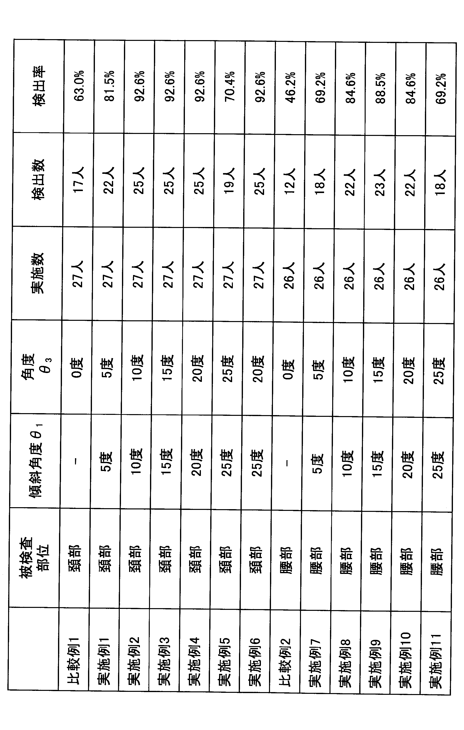
- the median nerve of the elbow was electrically stimulated (current 3 mA to 15 mA), and based on the output signal of the magnetic sensor array 16, how the nerve activity synchronized with the stimulation propagated through the nerve was measured at the neck. A total of 2000 averaged data was acquired. Only 17 out of 27 people could detect a weak propagation signal, and the signal detection rate was 63.0%.
- Example 1 X-ray imaging and cervical biomagnetism measurement are performed in the same manner as in Comparative Example 1 except that the magnetic measurement device 10 provided with the inclined gantry 11 is used instead of the magnetic measurement device 10x not provided with the inclined gantry 11. Carried out.
- the average value of the distance L was 107.1 mm, the maximum value was 151 mm, and the minimum value was 93 mm.
- the distance L was significantly shorter than that of Comparative Example 1. Note that the significant shortening of the distance L means a significant shortening of the distance between the spinal cord 511 and the sensor surface 15a of the magnetic sensor 15 facing each cervical vertebra.
- the average value of the distance L was 103.1 mm, the maximum value was 121 mm, and the minimum value was 87 mm.
- the distance L was further shortened than that of Example 1.
- the average value of the distance L was 101.1 mm, the maximum value was 120 mm, and the minimum value was 87 mm.
- the distance L was not significantly different from Example 2.
- the average value of the distance L was 100.1 mm, the maximum value was 121 mm, and the minimum value was 85 mm, and the distance L was not significantly different from Example 2 and Example 3.
- the average value of the distance L was 100.7 mm, the maximum value was 121 mm, and the minimum value was 84 mm.
- the distance L was not significantly different from those in Example 2, Example 3, and Example 4.
- the average value of the distance L was 100.7 mm, the maximum value was 124 mm, and the minimum value was 86 mm, and the distance L was not significantly different from Example 2, Example 3, and Example 4.
- Comparative Example 2 Except that the subject 500 is placed in a supine position on the horizontal bed 21, the waist is applied to the curved surface 14 a of the sensor cylinder 14, and the fifth lumbar vertebra is adjusted so as to substantially coincide with the center of the magnetic sensor array 16. Performed biomagnetism measurement in the same manner as in Comparative Example 1.
- Biomagnetic measurement was performed using the magnetic measurement device 10x, and the state of nerve activity synchronized with electrical stimulation propagating through the nerve was measured at the waist. A total of 2000 averaged data was acquired. Only 12 out of 26 people could detect a weak propagation signal, and the signal detection rate was 46.2%.
- the examination site is also the case of the waist in the case of cervical, angle theta 3 is found to be improved signal detection rate in the case of 20 degrees or less than 10 degrees.
- the case where the angle ⁇ 3 is 10 degrees or more and 20 degrees or less is, for example, the case where the inclination angle ⁇ 2 is 10 degrees or more and 20 degrees or less and the bed 21 is horizontal.
- the inclination angle ⁇ 2 is larger than 20 degrees, but the inclination angle adjusting mechanism of the bed 21 is adjusted so that the angle ⁇ 3 is 10 degrees or more and 20 degrees or less.
- the magnetic measuring device is not limited to a myelometer that detects a current traveling in the spinal cord as a magnetic field.
- the magnetic measurement apparatus can be used for a magnetoencephalograph, a magnetocardiograph, or the like.
- each magnetic sensor may be disposed along the inner surface of the curved surface.
- the inclination angle of the sensor surface of the magnetic sensor arranged at the center in the y direction with respect to the installation surface of the inclined mount is designed to be equal to the inclination angle of the inclined surface with respect to the installation surface of the inclined mount. That's fine.
Abstract
Description
(比較例1)
比較例1では、ベッド21、X線源22及びX線撮影用フィルム23、電気刺激装置24を備えた磁気計測装置10xを用いて計測を行った。但し、冷却機構13及び電気刺激装置24は磁気シールドルーム外に設置し、その他は磁気シールドルーム内に設置した。磁気計測装置10xは、傾斜架台11を備えていない点以外は、磁気計測装置10と同一である。つまり、磁気計測装置10xでは、低温容器12の底面が水平面に直接設置されており、水平面に対する各磁気センサ15のセンサ面15aの傾斜角度は0度である。 <Comparative Examples and Examples>
(Comparative Example 1)
In Comparative Example 1, measurement was performed using a magnetic measurement device 10 x including a
傾斜架台11を備えていない磁気計測装置10xに代えて、傾斜架台11を備えている磁気計測装置10を用いた以外は、比較例1と同様の方法で、X線撮影及び頚部の生体磁気計測を実施した。 Example 1
X-ray imaging and cervical biomagnetism measurement are performed in the same manner as in Comparative Example 1 except that the
傾斜角度θ1=10度、傾斜角度θ2=10度とした以外は、実施例1と同様の方法で、X線撮影及び頚部の生体磁気計測を実施した。 (Example 2)
X-ray imaging and cervical biomagnetism measurement were performed in the same manner as in Example 1 except that the inclination angle θ 1 = 10 degrees and the inclination angle θ 2 = 10 degrees.
傾斜角度θ1=15度、傾斜角度θ2=15度とした以外は、実施例1と同様の方法で、X線撮影及び頚部の生体磁気計測を実施した。 (Example 3)
X-ray imaging and cervical biomagnetism measurement were performed in the same manner as in Example 1 except that the inclination angle θ 1 = 15 degrees and the inclination angle θ 2 = 15 degrees.
傾斜角度θ1=20度、傾斜角度θ2=20度とした以外は、実施例1と同様の方法で、X線撮影及び頚部の生体磁気計測を実施した。 Example 4
X-ray imaging and cervical biomagnetic measurement were performed in the same manner as in Example 1 except that the inclination angle θ 1 = 20 degrees and the inclination angle θ 2 = 20 degrees.
傾斜角度θ1=25度、傾斜角度θ2=25度とした以外は、実施例1と同様の方法で、X線撮影及び頚部の生体磁気計測を実施した。 (Example 5)
X-ray imaging and cervical biomagnetism measurement were performed in the same manner as in Example 1 except that the inclination angle θ 1 = 25 degrees and the inclination angle θ 2 = 25 degrees.
傾斜角度θ1=25度、傾斜角度θ2=25度とした。そして、ベッド21の傾斜調整機構を利用して、傾斜が5度緩やかになる方向(被検体500の頭側を持ち上げる方向)にベッド21の傾斜角度を設定し、角度θ3を20度とした以外は、実施例1と同様の方法で、X線撮影及び頚部の生体磁気計測を実施した。 (Example 6)
The inclination angle θ 1 = 25 degrees and the inclination angle θ 2 = 25 degrees. Then, by utilizing the tilt adjustment mechanism of the
水平なベッド21上で被検体500に仰臥位となってもらい、センサ筒14の湾曲面14aに腰部を当てるようにし、第5腰椎が磁気センサアレイ16の中心と略一致するように調整した以外は、比較例1と同様の方法で、生体磁気計測を実施した。 (Comparative Example 2)
Except that the subject 500 is placed in a supine position on the
傾斜角度θ1=5度、傾斜角度θ2=5度とした以外は、比較例2と同様の方法で、X線撮影及び腰部の生体磁気計測を実施した。 (Example 7)
X-ray imaging and waist biomagnetism measurement were performed in the same manner as in Comparative Example 2 except that the inclination angle θ 1 = 5 degrees and the inclination angle θ 2 = 5 degrees.
傾斜角度θ1=10度、傾斜角度θ2=10度とした以外は、実施例7と同様の方法で、X線撮影及び腰部の生体磁気計測を実施した。 (Example 8)
X-ray imaging and waist biomagnetism measurement were performed in the same manner as in Example 7 except that the inclination angle θ 1 = 10 degrees and the inclination angle θ 2 = 10 degrees.
傾斜角度θ1=15度、傾斜角度θ2=15度とした以外は、実施例7と同様の方法で、X線撮影及び腰部の生体磁気計測を実施した。 Example 9
X-ray imaging and waist biomagnetism measurement were performed in the same manner as in Example 7 except that the inclination angle θ 1 = 15 degrees and the inclination angle θ 2 = 15 degrees.
傾斜角度θ1=20度、傾斜角度θ2=20度とした以外は、実施例7と同様の方法で、X線撮影及び腰部の生体磁気計測を実施した。 (Example 10)
X-ray imaging and waist biomagnetism measurement were performed in the same manner as in Example 7 except that the inclination angle θ 1 = 20 degrees and the inclination angle θ 2 = 20 degrees.
傾斜角度θ1=25度、傾斜角度θ2=25度とした以外は、実施例7と同様の方法で、X線撮影及び腰部の生体磁気計測を実施した。 (Example 11)
X-ray imaging and waist biomagnetism measurement were performed in the same manner as in Example 7 except that the inclination angle θ 1 = 25 degrees and the inclination angle θ 2 = 25 degrees.
各比較例及び各実施例の結果を表1にまとめた。 (Summary)
The results of each comparative example and each example are summarized in Table 1.
11 傾斜架台
11a 設置面
11b 傾斜面
12 低温容器
13 冷却機構
14 センサ筒
14a 湾曲面
15 磁気センサ
15a センサ面
16 磁気センサアレイ
17 流路
21 ベッド
22 X線源
23 X線撮影用フィルム
24 電気刺激装置
141 内槽
142 外槽
151、153 円柱状ブロック
152a、152b、152c SQUID DESCRIPTION OF
Claims (10)
- 設置面、及び前記設置面に対して傾斜する傾斜面を備えた傾斜架台と、
前記傾斜面に設置された低温容器と、
前記低温容器に接続された冷却機構と、
前記低温容器に接続され、所定方向には湾曲せず前記所定方向に直交する方向には両端より中央が飛び出すように湾曲する湾曲面を備えたセンサ筒と、
前記センサ筒内に、センサ面を前記湾曲面の側に向けて収容された、生体磁気を計測する磁気センサと、を有し、
前記センサ面が、前記設置面に対して、前記傾斜面と同一方向に傾斜している磁気計測装置。 An inclined mount with an installation surface and an inclined surface inclined with respect to the installation surface;
A cryogenic container installed on the inclined surface;
A cooling mechanism connected to the cryogenic vessel;
A sensor cylinder having a curved surface connected to the cryogenic vessel and curved so that the center protrudes from both ends in a direction orthogonal to the predetermined direction without being bent in the predetermined direction;
A magnetic sensor for measuring biomagnetism accommodated in the sensor cylinder with the sensor surface facing the curved surface;
The magnetic measurement apparatus in which the sensor surface is inclined in the same direction as the inclined surface with respect to the installation surface. - 前記設置面に対する前記センサ面の傾斜角度は、前記設置面に対する前記傾斜面の傾斜角度に等しい請求項1に記載の磁気計測装置。 The magnetic measurement device according to claim 1, wherein an inclination angle of the sensor surface with respect to the installation surface is equal to an inclination angle of the inclined surface with respect to the installation surface.
- 前記センサ筒内に、センサ面を前記湾曲面の側に向けて収容された、生体磁気を計測する複数の磁気センサを備え、
夫々の前記磁気センサのセンサ面が、前記設置面に対して、前記傾斜面と同一方向に傾斜している請求項1に記載の磁気計測装置。 A plurality of magnetic sensors for measuring biomagnetism, housed in the sensor cylinder with the sensor surface facing the curved surface,
The magnetic measurement device according to claim 1, wherein a sensor surface of each of the magnetic sensors is inclined in the same direction as the inclined surface with respect to the installation surface. - 前記設置面に対する夫々の前記磁気センサのセンサ面の傾斜角度は、前記設置面に対する前記傾斜面の傾斜角度に等しい請求項3に記載の磁気計測装置。 4. The magnetic measurement device according to claim 3, wherein an inclination angle of each of the magnetic sensors with respect to the installation surface is equal to an inclination angle of the inclined surface with respect to the installation surface.
- 前記センサ筒内の前記所定方向に直交する方向における収容位置が、前記湾曲面の両端側よりも前記湾曲面の中央側に近い前記磁気センサのセンサ面ほど、前記湾曲面の側に飛び出している請求項3に記載の磁気計測装置。 The accommodation position in the direction perpendicular to the predetermined direction in the sensor cylinder protrudes toward the curved surface as the sensor surface of the magnetic sensor is closer to the center side of the curved surface than both ends of the curved surface. The magnetic measurement apparatus according to claim 3.
- 前記傾斜角度が10度以上20度以下である請求項2に記載の磁気計測装置。 The magnetic measuring device according to claim 2, wherein the inclination angle is 10 degrees or more and 20 degrees or less.
- 前記設置面に対する前記センサ面の傾斜角度は固定値である請求項1に記載の磁気計測装置。 The magnetic measuring device according to claim 1, wherein an inclination angle of the sensor surface with respect to the installation surface is a fixed value.
- 前記湾曲面の上側を含む空間をX線撮影するX線撮影手段と、
被検体に対して経皮的に電流を送電し、目的とする神経を刺激する電気刺激装置と、を有する請求項1に記載の磁気計測装置。 X-ray imaging means for X-ray imaging of a space including the upper side of the curved surface;
The magnetic measurement device according to claim 1, further comprising: an electrical stimulation device that transcutaneously transmits a current to the subject and stimulates a target nerve. - 前記刺激に同期した神経活動の伝搬を前記磁気センサで計測する請求項8に記載の磁気計測装置。 The magnetic measurement device according to claim 8, wherein propagation of neural activity synchronized with the stimulus is measured by the magnetic sensor.
- 被検体の被検査部位が前記湾曲面に接するように、前記被検体を寝かせるベッドを有し、
前記ベッドは、前記センサ面に対する前記被検査部位の角度を緩める方向に調整可能な傾斜調整機構を備えている請求項1に記載の磁気計測装置。 A bed on which the subject is laid so that a portion to be examined of the subject contacts the curved surface;
The magnetic measurement apparatus according to claim 1, wherein the bed includes an inclination adjustment mechanism that can be adjusted in a direction of loosening an angle of the inspected portion with respect to the sensor surface.
Priority Applications (5)
| Application Number | Priority Date | Filing Date | Title |
|---|---|---|---|
| JP2018503025A JP6602456B2 (en) | 2016-03-03 | 2017-02-17 | Magnetic measuring device |
| CN201780013786.2A CN108778114B (en) | 2016-03-03 | 2017-02-17 | Magnetic measuring device |
| ES17759677T ES2809741T3 (en) | 2016-03-03 | 2017-02-17 | Magnetic measuring device |
| EP17759677.2A EP3424419B1 (en) | 2016-03-03 | 2017-02-17 | Magnetic measuring device |
| US16/116,148 US10918293B2 (en) | 2016-03-03 | 2018-08-29 | Magnetic measuring apparatus |
Applications Claiming Priority (2)
| Application Number | Priority Date | Filing Date | Title |
|---|---|---|---|
| JP2016-041406 | 2016-03-03 | ||
| JP2016041406 | 2016-03-03 |
Related Child Applications (1)
| Application Number | Title | Priority Date | Filing Date |
|---|---|---|---|
| US16/116,148 Continuation US10918293B2 (en) | 2016-03-03 | 2018-08-29 | Magnetic measuring apparatus |
Publications (1)
| Publication Number | Publication Date |
|---|---|
| WO2017150207A1 true WO2017150207A1 (en) | 2017-09-08 |
Family
ID=59744110
Family Applications (1)
| Application Number | Title | Priority Date | Filing Date |
|---|---|---|---|
| PCT/JP2017/005824 WO2017150207A1 (en) | 2016-03-03 | 2017-02-17 | Magnetic measuring device |
Country Status (6)
| Country | Link |
|---|---|
| US (1) | US10918293B2 (en) |
| EP (1) | EP3424419B1 (en) |
| JP (1) | JP6602456B2 (en) |
| CN (1) | CN108778114B (en) |
| ES (1) | ES2809741T3 (en) |
| WO (1) | WO2017150207A1 (en) |
Cited By (6)
| Publication number | Priority date | Publication date | Assignee | Title |
|---|---|---|---|---|
| JP2018051097A (en) * | 2016-09-30 | 2018-04-05 | 国立大学法人 東京医科歯科大学 | Biological information measurement device |
| JP2019098156A (en) * | 2017-12-01 | 2019-06-24 | 株式会社リコー | Biomagnetism measurement device, biological information measurement device, and biomagnetism measurement method |
| JP2019207191A (en) * | 2018-05-30 | 2019-12-05 | 独立行政法人石油天然ガス・金属鉱物資源機構 | Magnetic measuring device, cooling device and magnetic survey system |
| US11375934B2 (en) | 2017-12-01 | 2022-07-05 | Ricoh Company, Ltd. | Biomagnetic measurement apparatus, biological information measurement apparatus, and biomagnetic measurement method |
| US11437123B2 (en) | 2018-03-19 | 2022-09-06 | Ricoh Company, Ltd. | Biological information processing apparatus and biological information processing system |
| JP7385217B2 (en) | 2020-03-23 | 2023-11-22 | 株式会社リコー | Biocurrent estimation method, biocurrent estimation device, and biomagnetic measurement system |
Families Citing this family (5)
| Publication number | Priority date | Publication date | Assignee | Title |
|---|---|---|---|---|
| JP7366817B2 (en) | 2020-03-23 | 2023-10-23 | 株式会社リコー | Helium circulation system, cryogenic freezing method, and biomagnetic measurement device |
| JP2021148407A (en) | 2020-03-23 | 2021-09-27 | 株式会社リコー | Cryogenic refrigerating machine and biomagnetism measuring apparatus |
| CN117378298A (en) * | 2021-05-28 | 2024-01-09 | 株式会社有泽制作所 | Heat insulation container and spine magnetometer using same |
| CN113945608A (en) * | 2021-09-30 | 2022-01-18 | 中国计量大学 | Magnetic induction phase shift measurement system based on magnetoelectric sensor |
| USD988545S1 (en) | 2023-03-17 | 2023-06-06 | Ruihe Ying | Slab comprising particulate mineral mixture |
Citations (6)
| Publication number | Priority date | Publication date | Assignee | Title |
|---|---|---|---|---|
| JPS4834076B1 (en) | 1969-05-23 | 1973-10-18 | ||
| JPH02114941A (en) * | 1988-09-16 | 1990-04-27 | Siemens Ag | Magnetometer device |
| JP2002136493A (en) * | 2001-03-26 | 2002-05-14 | Hitachi Ltd | Magnetic field measuring instrument |
| JP2008206809A (en) * | 2007-02-27 | 2008-09-11 | Kanazawa Inst Of Technology | Biomagnetism measuring apparatus |
| JP4397276B2 (en) | 2004-05-26 | 2010-01-13 | 学校法人金沢工業大学 | Superconducting magnetometer and superconducting magnetometer system |
| JP2012020143A (en) * | 2006-02-23 | 2012-02-02 | Kanazawa Inst Of Technology | Control method of superconducting magnetism measuring apparatus |
Family Cites Families (29)
| Publication number | Priority date | Publication date | Assignee | Title |
|---|---|---|---|---|
| JPS5137149B2 (en) | 1971-10-04 | 1976-10-14 | ||
| DE8202647U1 (en) * | 1982-02-03 | 1982-08-19 | R. Jung GmbH, 6907 Nußloch | CRYOSTAT MICROTOM |
| JP2590182B2 (en) | 1987-03-07 | 1997-03-12 | 株式会社東芝 | Blackening furnace and method of manufacturing shadow mask using this blackening furnace |
| US5302831A (en) * | 1992-04-30 | 1994-04-12 | North American Philips Corporation | Dewar construction for cooling radiation detector cold finger |
| JP3106701B2 (en) | 1992-06-29 | 2000-11-06 | ダイキン工業株式会社 | Biomagnetic field measurement device |
| JP3541079B2 (en) * | 1995-03-24 | 2004-07-07 | 株式会社ミツバ | Tilt sensor |
| US6842637B2 (en) * | 1997-10-24 | 2005-01-11 | Hitachi, Ltd. | Magnetic field measurement apparatus |
| JP4034429B2 (en) | 1998-07-31 | 2008-01-16 | 株式会社東芝 | Biomagnetic measurement device |
| US6275719B1 (en) * | 1998-09-09 | 2001-08-14 | Hitachi, Ltd. | Biomagnetic field measurement apparatus |
| JP3454246B2 (en) * | 2000-10-30 | 2003-10-06 | 株式会社日立製作所 | Magnetic field measurement device |
| JP4013492B2 (en) | 2001-03-26 | 2007-11-28 | 株式会社日立製作所 | Magnetic field shielding device and biomagnetic field measuring device using the same |
| JP2003304851A (en) | 2002-04-12 | 2003-10-28 | Ishii Ind Co Ltd | Apparatus for cutting field crop to equal size |
| JP4521239B2 (en) * | 2004-09-10 | 2010-08-11 | 株式会社日立ハイテクノロジーズ | Magnetic field shielding device and biomagnetic field measuring device |
| JP4397315B2 (en) * | 2004-09-28 | 2010-01-13 | 学校法人金沢工業大学 | Superconducting magnetometer |
| JP2006228935A (en) | 2005-02-17 | 2006-08-31 | Ricoh Co Ltd | Organic thin film transistor |
| JP2006304851A (en) * | 2005-04-26 | 2006-11-09 | Tokyo Medical & Dental Univ | Method of sampling data on spinal cord evoked magnetic field and method of measuring spine induced magnetic field |
| JP5167707B2 (en) | 2006-08-04 | 2013-03-21 | 株式会社リコー | Multilayer structure, multilayer wiring board, active matrix substrate, and electronic display device |
| US20110251468A1 (en) * | 2010-04-07 | 2011-10-13 | Ivan Osorio | Responsiveness testing of a patient having brain state changes |
| JP4748231B2 (en) * | 2009-02-24 | 2011-08-17 | トヨタ自動車株式会社 | Eddy current measuring sensor and inspection method therefor |
| JP5293267B2 (en) | 2009-02-26 | 2013-09-18 | 株式会社リコー | Display device |
| CN201452400U (en) * | 2009-04-30 | 2010-05-12 | 余明月 | Multifunctional lumbar vertebra and cervical vertebra health care backrest |
| JP5446982B2 (en) | 2009-05-01 | 2014-03-19 | 株式会社リコー | Image display panel and image display device |
| US9010202B2 (en) * | 2010-07-28 | 2015-04-21 | Halina Stabacinskiene | Cryogenic specimen holder |
| CN203041467U (en) * | 2013-01-06 | 2013-07-10 | 杜传奎 | Single-vertical-column multifunctional electric bed |
| JP2014143333A (en) | 2013-01-25 | 2014-08-07 | Ricoh Co Ltd | Solid dye-sensitized solar cell and solid dye-sensitized solar cell module |
| US10222444B2 (en) * | 2014-05-09 | 2019-03-05 | The General Hospital Corporation | Systems and methods for moving magnetic resonance imaging |
| CN104068852A (en) * | 2014-06-28 | 2014-10-01 | 苏州格林泰克科技有限公司 | Bio-electricity signal sensor |
| KR101632280B1 (en) * | 2014-09-05 | 2016-07-01 | 한국표준과학연구원 | Cryocooled SQUID Measuring system |
| JP2017015620A (en) | 2015-07-03 | 2017-01-19 | 株式会社リコー | Magnetic shield device, magnetic filed noise reduction method, and spinal cord induction magnetic field measuring system |
-
2017
- 2017-02-17 CN CN201780013786.2A patent/CN108778114B/en active Active
- 2017-02-17 EP EP17759677.2A patent/EP3424419B1/en active Active
- 2017-02-17 ES ES17759677T patent/ES2809741T3/en active Active
- 2017-02-17 WO PCT/JP2017/005824 patent/WO2017150207A1/en active Application Filing
- 2017-02-17 JP JP2018503025A patent/JP6602456B2/en active Active
-
2018
- 2018-08-29 US US16/116,148 patent/US10918293B2/en active Active
Patent Citations (6)
| Publication number | Priority date | Publication date | Assignee | Title |
|---|---|---|---|---|
| JPS4834076B1 (en) | 1969-05-23 | 1973-10-18 | ||
| JPH02114941A (en) * | 1988-09-16 | 1990-04-27 | Siemens Ag | Magnetometer device |
| JP2002136493A (en) * | 2001-03-26 | 2002-05-14 | Hitachi Ltd | Magnetic field measuring instrument |
| JP4397276B2 (en) | 2004-05-26 | 2010-01-13 | 学校法人金沢工業大学 | Superconducting magnetometer and superconducting magnetometer system |
| JP2012020143A (en) * | 2006-02-23 | 2012-02-02 | Kanazawa Inst Of Technology | Control method of superconducting magnetism measuring apparatus |
| JP2008206809A (en) * | 2007-02-27 | 2008-09-11 | Kanazawa Inst Of Technology | Biomagnetism measuring apparatus |
Cited By (8)
| Publication number | Priority date | Publication date | Assignee | Title |
|---|---|---|---|---|
| JP2018051097A (en) * | 2016-09-30 | 2018-04-05 | 国立大学法人 東京医科歯科大学 | Biological information measurement device |
| JP2019098156A (en) * | 2017-12-01 | 2019-06-24 | 株式会社リコー | Biomagnetism measurement device, biological information measurement device, and biomagnetism measurement method |
| US11375934B2 (en) | 2017-12-01 | 2022-07-05 | Ricoh Company, Ltd. | Biomagnetic measurement apparatus, biological information measurement apparatus, and biomagnetic measurement method |
| JP7176689B2 (en) | 2017-12-01 | 2022-11-22 | 株式会社リコー | Biomagnetism measuring device and biomagnetism measuring method |
| US11437123B2 (en) | 2018-03-19 | 2022-09-06 | Ricoh Company, Ltd. | Biological information processing apparatus and biological information processing system |
| JP2019207191A (en) * | 2018-05-30 | 2019-12-05 | 独立行政法人石油天然ガス・金属鉱物資源機構 | Magnetic measuring device, cooling device and magnetic survey system |
| JP7116418B2 (en) | 2018-05-30 | 2022-08-10 | 独立行政法人石油天然ガス・金属鉱物資源機構 | Magnetic measuring device and magnetic exploration system |
| JP7385217B2 (en) | 2020-03-23 | 2023-11-22 | 株式会社リコー | Biocurrent estimation method, biocurrent estimation device, and biomagnetic measurement system |
Also Published As
| Publication number | Publication date |
|---|---|
| JP6602456B2 (en) | 2019-11-06 |
| ES2809741T3 (en) | 2021-03-05 |
| EP3424419A1 (en) | 2019-01-09 |
| CN108778114B (en) | 2022-03-01 |
| US20190059758A1 (en) | 2019-02-28 |
| CN108778114A (en) | 2018-11-09 |
| JPWO2017150207A1 (en) | 2019-01-24 |
| US10918293B2 (en) | 2021-02-16 |
| EP3424419B1 (en) | 2020-07-01 |
| EP3424419A4 (en) | 2019-03-20 |
Similar Documents
| Publication | Publication Date | Title |
|---|---|---|
| JP6602456B2 (en) | Magnetic measuring device | |
| KOLÁŘ et al. | Analysis of diaphragm movement during tidal breathing and during its activation while breath holding using MRI synchronized with spirometry. | |
| JP4834076B2 (en) | Superconducting magnetometer | |
| EP1274347B1 (en) | Breathing movement measurements and apparatus | |
| US20160174869A1 (en) | Electrode device for measuring impedance of human body and apparatus comprising the same | |
| EP2432384B1 (en) | Arrangement for detecting magnetic particles and for monitoring bleeding | |
| US20160296293A1 (en) | Apparatus for robotic surgery | |
| US20080194982A1 (en) | Method and Apparatus for Inductively Measuring the Bio-Impedance of a Users Body | |
| JP2006304851A (en) | Method of sampling data on spinal cord evoked magnetic field and method of measuring spine induced magnetic field | |
| Richer et al. | Eddy current based flexible sensor for contactless measurement of breathing | |
| Furlong et al. | Cortical localisation of magnetic fields evoked by oesophageal distension | |
| CN208384093U (en) | Magnetic resonance line coil assembly and magnetic resonance scanning system | |
| US9730610B1 (en) | Magnetic resonance imaging of the spine to detect scoliosis | |
| Adachi et al. | A SQUID system for measurement of spinal cord evoked field of supine subjects | |
| Kober et al. | Fit of the digitized head surface with the surface reconstructed from MRI tomography | |
| CN106137202A (en) | Magnetic resonance compatible respiratory training and independently adjusting means and using method thereof | |
| CN206063142U (en) | Magnetic resonance compatible respiratory training and autonomous adjusting means | |
| Zhang et al. | Human CT measurements of structure/electrode position changes during respiration with electrical impedance tomography | |
| Adachi et al. | A SQUID biomagnetometer system for measurement of spinal cord evoked magnetic fields | |
| Frerichs et al. | Electrical impedance tomography in acute respiratory distress syndrome | |
| WO2021070059A1 (en) | Devices, systems, and methods for assessing lung characteristics via regional impedance and patient positioning | |
| JPH01249045A (en) | Cerebral aneurysm clip | |
| Klein et al. | Magnetoneurographic registration of propagating magnetic fields in the lumbar spine after stimulation of the posterior tibial nerve | |
| Zhao et al. | EIT image reconstruction with individual thorax geometry | |
| US7438074B1 (en) | Method for assessing the condition of the spine |
Legal Events
| Date | Code | Title | Description |
|---|---|---|---|
| WWE | Wipo information: entry into national phase |
Ref document number: 2018503025 Country of ref document: JP |
|
| NENP | Non-entry into the national phase |
Ref country code: DE |
|
| WWE | Wipo information: entry into national phase |
Ref document number: 2017759677 Country of ref document: EP |
|
| ENP | Entry into the national phase |
Ref document number: 2017759677 Country of ref document: EP Effective date: 20181004 |
|
| 121 | Ep: the epo has been informed by wipo that ep was designated in this application |
Ref document number: 17759677 Country of ref document: EP Kind code of ref document: A1 |