WO2017146388A1 - 무선 통신 시스템에서 스케줄링 요청을 전송하는 방법 및 장치 - Google Patents
무선 통신 시스템에서 스케줄링 요청을 전송하는 방법 및 장치 Download PDFInfo
- Publication number
- WO2017146388A1 WO2017146388A1 PCT/KR2017/001062 KR2017001062W WO2017146388A1 WO 2017146388 A1 WO2017146388 A1 WO 2017146388A1 KR 2017001062 W KR2017001062 W KR 2017001062W WO 2017146388 A1 WO2017146388 A1 WO 2017146388A1
- Authority
- WO
- WIPO (PCT)
- Prior art keywords
- resource
- scheduling request
- information
- terminal
- resources
- Prior art date
Links
Images


Classifications
-
- H—ELECTRICITY
- H04—ELECTRIC COMMUNICATION TECHNIQUE
- H04W—WIRELESS COMMUNICATION NETWORKS
- H04W72/00—Local resource management
- H04W72/04—Wireless resource allocation
-
- H—ELECTRICITY
- H04—ELECTRIC COMMUNICATION TECHNIQUE
- H04W—WIRELESS COMMUNICATION NETWORKS
- H04W24/00—Supervisory, monitoring or testing arrangements
- H04W24/10—Scheduling measurement reports ; Arrangements for measurement reports
-
- H—ELECTRICITY
- H04—ELECTRIC COMMUNICATION TECHNIQUE
- H04L—TRANSMISSION OF DIGITAL INFORMATION, e.g. TELEGRAPHIC COMMUNICATION
- H04L5/00—Arrangements affording multiple use of the transmission path
- H04L5/003—Arrangements for allocating sub-channels of the transmission path
- H04L5/0053—Allocation of signaling, i.e. of overhead other than pilot signals
-
- H—ELECTRICITY
- H04—ELECTRIC COMMUNICATION TECHNIQUE
- H04L—TRANSMISSION OF DIGITAL INFORMATION, e.g. TELEGRAPHIC COMMUNICATION
- H04L5/00—Arrangements affording multiple use of the transmission path
- H04L5/0091—Signaling for the administration of the divided path
-
- H—ELECTRICITY
- H04—ELECTRIC COMMUNICATION TECHNIQUE
- H04W—WIRELESS COMMUNICATION NETWORKS
- H04W72/00—Local resource management
- H04W72/02—Selection of wireless resources by user or terminal
-
- H—ELECTRICITY
- H04—ELECTRIC COMMUNICATION TECHNIQUE
- H04W—WIRELESS COMMUNICATION NETWORKS
- H04W72/00—Local resource management
- H04W72/20—Control channels or signalling for resource management
-
- H—ELECTRICITY
- H04—ELECTRIC COMMUNICATION TECHNIQUE
- H04W—WIRELESS COMMUNICATION NETWORKS
- H04W72/00—Local resource management
- H04W72/20—Control channels or signalling for resource management
- H04W72/23—Control channels or signalling for resource management in the downlink direction of a wireless link, i.e. towards a terminal
-
- H—ELECTRICITY
- H04—ELECTRIC COMMUNICATION TECHNIQUE
- H04W—WIRELESS COMMUNICATION NETWORKS
- H04W72/00—Local resource management
- H04W72/50—Allocation or scheduling criteria for wireless resources
- H04W72/54—Allocation or scheduling criteria for wireless resources based on quality criteria
- H04W72/543—Allocation or scheduling criteria for wireless resources based on quality criteria based on requested quality, e.g. QoS
Definitions
- the present disclosure relates to wireless communication, and more particularly, to a method for transmitting a scheduling request in a wireless communication system and a device using the same.
- Wireless communication systems are widely deployed to provide various kinds of communication services such as voice and data.
- the purpose of a wireless communication system is to allow a large number of terminals to perform reliable communication regardless of location and mobility.
- a wireless communication system is a multiple access system capable of supporting communication with a plurality of terminals by sharing available radio resources.
- radio resources include time, frequency, code, transmit power, and the like.
- multiple access systems include time division multiple access (TDMA) systems, code division multiple access (CDMA) systems, frequency division multiple access (FDMA) systems, orthogonal frequency division multiple access (OFDMA) systems, and single carrier frequency (SC-FDMA). division multiple access) system.
- TDMA time division multiple access
- CDMA code division multiple access
- FDMA frequency division multiple access
- OFDMA orthogonal frequency division multiple access
- SC-FDMA single carrier frequency division multiple access
- the base station appropriately allocates radio resources to terminals in the cell through scheduling.
- the terminal may transmit control information or user data to the base station by using the allocated radio resource.
- the control information transmission method and the user data transmission method may be different.
- a radio resource allocation scheme for control information and a radio resource allocation scheme for user data may also be different. Therefore, the radio resource for the control information and the radio resource for the user data may be different.
- the base station may manage a radio resource reserved for control information and a radio resource reserved for user data.
- a time taken for transmission of control information or user data on one subframe is called a transmission time interval (TTI).
- TTI transmission time interval
- one subframe has a length of 1 ms.
- the latency on the user plane is 1 ms. That is, a 1ms long TTI has a structure that is not suitable for low latency requirements in next generation wireless communication systems. Accordingly, there is a need for a method of arranging a radio resource structure for satisfying lower latency by controlling a short TTI obtained by dividing an existing TTI into smaller units.
- the present disclosure provides a method and apparatus for transmitting a scheduling request in a wireless communication system.
- the present specification proposes a method for transmitting a scheduling request in a wireless communication system.
- the first scheduling request (SR) resources and the second scheduling request (SR) resources are resources for the terminal to transmit the scheduling request.
- the first and second scheduling request resources may be classified as having different resource allocation periods, and the allocation period of the first scheduling request resource is shorter than the allocation period of the second scheduling request resource.
- a dedicated scheduling request resource and a common scheduling request resource may be allocated, and in the second scheduling request resource, a dedicated scheduling request resource may be allocated.
- the first scheduling request resource has a possibility of allocating a common scheduling request resource.
- the UE periodically transmits a channel quality indicator (CQI), a precoding matrix indicator (PMI), and a sounding reference signal (SRS) to the base station.
- CQI channel quality indicator
- PMI precoding matrix indicator
- SRS sounding reference signal
- the base station can estimate the location of the terminal through the PMI information.
- the PMI information includes a PMI index.
- a common scheduling request resource or a dedicated scheduling request resource is arranged according to the PMI. That is, the base station informs the terminal of the change pattern of the scheduling request resource according to the PMI change.
- the terminal receives information on the first scheduling request resource and the second scheduling request resource broadcast from the base station. Since the information about the first and second scheduling request resources that are broadcast is delivered cell-specifically, the terminals in the cell mainly receive information about the region of the scheduling request resources.
- the information about the broadcasted first scheduling request resource includes a first indicator indicating whether a common scheduling request resource is allocated in the first scheduling request resource.
- the information on the broadcasted first scheduling request resource may further include a period in which the terminal feeds back the PMI to the base station and a period in which the terminal transmits the SRS to the base station.
- SIB system information block
- the common scheduling request resource is allocated from the first scheduling request resource, and if the first indicator does not indicate the predetermined value, the common scheduling request resource is not allocated from the first scheduling request resource. Only dedicated scheduling request resources are allocated.
- the terminal receives information on the first scheduling request resource and the second scheduling request resource transmitted from the base station to the terminal.
- the specified terminal since the information about the first and second scheduling request resources is transmitted to the terminal, the specified terminal receives the more specific information about the scheduling request resources.
- the information on the second scheduling request resource which is specifically transmitted to the terminal, may be determined in the second scheduling request resource if the common scheduling request resource is allocated from the first scheduling request resource (the first indicator indicates a predetermined value).
- a second indicator indicating that the resource is allocated.
- the terminal may receive allocation information indicating that the common scheduling request resource is allocated in the first scheduling request resource and allocation information indicating that the dedicated scheduling request resource is allocated in the second scheduling request resource according to the second indicator.
- the second indicator may further indicate that a dedicated scheduling request resource is not allocated in the second scheduling request resource if the dedicated scheduling request resource is allocated in the first scheduling request resource (as the first indicator does not indicate a predetermined value). It may be. This is because it is not necessary to allocate the dedicated scheduling request resource to the second scheduling request resource since the dedicated scheduling request resource for the specific terminal is already allocated in the first scheduling request resource.
- the terminal receives information on the first and second scheduling request resources that are specifically transmitted through the terminal through a radio resource control (RRC) or a physical downlink control channel (PDCCH).
- RRC radio resource control
- PDCH physical downlink control channel
- the terminal is based on information about the first and second scheduling request resources that are broadcast and information about the first and second scheduling request resources that are specifically transmitted to the terminal, and selects one of the first scheduling request resources and the second scheduling request resources. Select one resource.
- the terminal receives allocation information for both the first scheduling request resource and the second scheduling request resource, but actually selects one resource for transmitting the scheduling request.
- the terminal selects a resource for transmitting the scheduling request from the first scheduling request resource and the second scheduling request resource.
- the third indicator indicating how to select the scheduling request resource is included in the information on the second scheduling request resource that is specifically transmitted to the terminal.
- a method of selecting a scheduling request resource is firstly a method of selecting a second scheduling request resource if the first scheduling request resource and the second scheduling request resource are in the same subframe.
- the second scheduling request resource is selected when the second scheduling request resource exists within the maximum scheduling request delay time, and the first scheduling when the second scheduling request resource does not exist within the maximum scheduling request delay time.
- the requesting resource is selected.
- information on a service for performing a scheduling request using the first and second scheduling request resources includes a radio bearer identifier (ID) or a quality of service identifier (QoS).
- ID radio bearer identifier
- QoS quality of service identifier
- the terminal transmits a scheduling request through the selected resource.
- the base station transmits an uplink grant according to a scheduling request of the terminal, thereby allocating radio resources for transmitting the uplink data by the terminal.
- the present specification proposes a terminal (device) for transmitting a scheduling request in a wireless communication system.
- the first scheduling request (SR) resource and the second scheduling request (SR) resource are resources for transmitting a scheduling request by the terminal.
- the first and second scheduling request resources may be classified as having different resource allocation periods, and the allocation period of the first scheduling request resource is shorter than the allocation period of the second scheduling request resource.
- a dedicated scheduling request resource and a common scheduling request resource may be allocated, and in the second scheduling request resource, a dedicated scheduling request resource may be allocated.
- the first scheduling request resource has a possibility of allocating a common scheduling request resource.
- the terminal includes a radio frequency (RF) unit for transmitting and receiving a radio signal and a processor connected to the RF unit.
- RF radio frequency
- the processor receives information about the first scheduling request resource and the second scheduling request resource broadcast from the base station. Since the information about the first and second scheduling request resources that are broadcast is delivered cell-specifically, the terminals in the cell mainly receive information about the region of the scheduling request resources.
- the information about the broadcasted first scheduling request resource includes a first indicator indicating whether a common scheduling request resource is allocated in the first scheduling request resource.
- the processor receives information about the first scheduling request resource and the second scheduling request resource that are specifically transmitted from the base station to the terminal.
- the specified terminal since the information about the first and second scheduling request resources is transmitted to the terminal, the specified terminal receives the more specific information about the scheduling request resources.
- the information on the second scheduling request resource, which is specifically transmitted to the terminal may be determined in the second scheduling request resource if the common scheduling request resource is allocated from the first scheduling request resource (the first indicator indicates a predetermined value).
- a second indicator indicating that the resource is allocated.
- the terminal may receive allocation information indicating that the common scheduling request resource is allocated in the first scheduling request resource and allocation information indicating that the dedicated scheduling request resource is allocated in the second scheduling request resource according to the second indicator.
- the processor may determine which one of the first scheduling request resource and the second scheduling request resource is based on information about the first and second scheduling request resources that are broadcast and information about the first and second scheduling request resources that are specifically transmitted to the terminal. Select one resource.
- the terminal receives allocation information for both the first scheduling request resource and the second scheduling request resource, but actually selects one resource for transmitting the scheduling request.
- the processor transmits a scheduling request through the selected resource.
- Applying the technique proposed in this specification has the effect of maintaining a constant probability of successfully receiving a scheduling request for each region even when the base station receives the scheduling request simultaneously.
- the proposed scheme increases the probability of receiving a scheduling request for each region.
- 1 shows a structure of a radio frame in 3GPP LTE.
- FIG. 2 is an exemplary diagram illustrating a resource grid for one uplink slot in 3GPP LTE.
- 3 shows an example of a structure of a downlink subframe in 3GPP LTE.
- FIG. 4 shows a structure of a radio frame including subframes and special symbols.
- FIG. 5 shows an example of a radio frame structure in which special symbols are continuously arranged at the front.
- FIG. 6 shows an example of a radio frame structure in which special symbols are continuously arranged behind.
- FIG. 7 shows a TDD radio frame structure in a 3GPP LTE system.
- FIG. 8 shows a control plane structure of a radio interface protocol between a terminal and an E-UTRAN.
- FIG. 9 illustrates a user plane structure of a radio interface protocol between a terminal and an E-UTRAN.
- FIG. 10 illustrates an example in which a first scheduling request resource and a second scheduling request resource are allocated according to an embodiment of the present specification.
- 11 is an exemplary diagram illustrating a process of receiving radio resource allocation through a scheduling request according to an embodiment of the present specification.
- FIG. 12 is a flowchart illustrating a procedure for transmitting a scheduling request by a terminal according to an embodiment of the present specification.
- FIG. 13 is a block diagram illustrating a device in which an embodiment of the present specification is implemented.
- CDMA code division multiple access
- FDMA frequency division multiple access
- TDMA time division multiple access
- OFDMA orthogonal frequency division multiple access
- SC-FDMA single carrier-frequency division multiple access
- CDMA may be implemented with a radio technology such as Universal Terrestrial Radio Access (UTRA) or CDMA2000.
- TDMA may be implemented with wireless technologies such as Global System for Mobile communications (GSM) / General Packet Radio Service (GPRS) / Enhanced Data Rates for GSM Evolution (EDGE).
- GSM Global System for Mobile communications
- GPRS General Packet Radio Service
- EDGE Enhanced Data Rates for GSM Evolution
- OFDMA may be implemented in a wireless technology such as IEEE 802.11 (Wi-Fi), IEEE 802.16 (WiMAX), IEEE 802-20, Evolved UTRA (E-UTRA).
- UTRA is part of the Universal Mobile Telecommunications System (UMTS).
- 3rd Generation Partnership Project (3GPP) long term evolution (LTE) is part of an Evolved UMTS (E-UMTS) using E-UTRA, and employs OFDMA in downlink and SC-FDMA in uplink.
- 3GPP 3rd Generation Partnership Project
- LTE long term evolution
- E-UMTS Evolved UMTS
- 1 shows a structure of a radio frame in 3GPP LTE.
- a radio frame consists of 10 subframes, and one subframe consists of two slots. Slots in a radio frame are numbered from 0 to 19 slots.
- the time taken for one subframe to be transmitted is called a transmission time interval (TTI).
- TTI may be referred to as a scheduling unit for data transmission.
- one radio frame may have a length of 10 ms
- one subframe may have a length of 1 ms
- one slot may have a length of 0.5 ms.
- the structure of the radio frame is merely an example, and the number of subframes included in the radio frame or the number of slots included in the subframe may be variously changed.
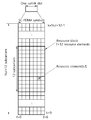
- FIG. 2 is an exemplary diagram illustrating a resource grid for one uplink slot in 3GPP LTE.
- an uplink slot includes a plurality of SC-FDMA symbols in a time domain and includes a Nul resource block (RB) in a frequency domain.
- the SC-FDMA symbol is used to represent one symbol period and may be called an OFDMA symbol or a symbol period according to a system.
- the RB includes a plurality of subcarriers in the frequency domain in resource allocation units.
- the number Nul of resource blocks included in the uplink slot depends on the uplink transmission bandwidth set in the cell.
- the uplink transmission bandwidth is system information.
- the terminal may know N ul by acquiring system information.
- Each element on the resource grid is called a resource element.
- an exemplary resource block includes 7 SC-FDMA symbols in the time domain and 7 ⁇ 12 resource elements including 12 subcarriers in the frequency domain, but the number of subcarriers in the resource block and the SC-FDMA symbol are exemplarily described.
- the number of is not limited thereto.
- the number of SC-FDMA symbols or the number of subcarriers included in the RB may be variously changed.
- the number of SC-FDMA symbols may be changed according to the length of a cyclic prefix (CP). For example, the number of SC-FDMA symbols is 7 for a normal CP and the number of SC-FDMA symbols is 6 for an extended CP.
- CP cyclic prefix
- a resource grid for one uplink slot may be applied to a resource grid for a downlink slot.
- the downlink slot includes a plurality of orthogonal frequency division multiplexing (OFDM) symbols in the time domain.
- OFDM orthogonal frequency division multiplexing
- 3 shows an example of a structure of a downlink subframe in 3GPP LTE.
- the downlink subframe includes two contiguous slots. Up to three OFDM symbols of the first slot in the downlink subframe are control regions to which a physical downlink control channel (PDCCH) is allocated, and the remaining OFDM symbols are data regions to which a physical downlink shared channel (PDSCH) is allocated. data region).
- the control region may be allocated a control channel such as a physical control format indicator channel (PCFICH) and a physical hybrid-ARQ indicator channel (PHICH).
- PCFICH physical control format indicator channel
- PHICH physical hybrid-ARQ indicator channel
- the control region includes 3 OFDM symbols.
- the number of OFDM symbols included in the control region in the subframe can be known through the PCFICH.
- the PHICH carries hybrid automatic repeat request (HARQ) acknowledgment (ACK) / not-acknowledgement (NACK) information in response to uplink data transmission.
- HARQ hybrid automatic repeat request
- ACK acknowledgment
- NACK not-acknowledgement
- the PDCCH may carry a downlink grant informing of resource allocation of downlink transmission on the PDSCH.
- the UE may read downlink user data transmitted through the PDSCH by decoding control information transmitted through the PDCCH.
- the PDCCH may carry control information used for physical uplink shared channel (PUSCH) scheduling to the UE.
- the control information used for PUSCH scheduling is an uplink grant informing of resource allocation of uplink transmission.
- the control region consists of a set of a plurality of control channel elements (CCE).
- the PDCCH is transmitted on an aggregation of one or several consecutive CCEs.
- the CCE corresponds to a plurality of resource element groups. Resource element groups are used to define control channel mappings to resource elements. If the total number of CCEs in the downlink subframe is N cce , the CCE is indexed from 0 to N cce , k-1. Since the number of OFDM symbols included in the control region in the subframe may change for each subframe, the total number of CCEs in the subframe may also change for each subframe.
- This time period resource transmission structure may be specified in units of terminals or may be specified to be commonly applied to a cell or a system-wide terminal. At the same time, it is possible to specify that the transmission structure is limited according to time or frequency band (subband).
- the terminal may be instructed by using a UE specific downlink physical control channel or UE specific RRC signaling. In case of UE common designation of a base station or a network, the UE may be instructed to the UE using UE common downlink physical control channel or UE common RRC signaling as system information.
- FIG. 4 shows a structure of a radio frame including subframes and special symbols.
- a time period transmission resource structure defining a may be illustrated.
- Each subframe has a length of 0.214 ms.
- the positions of the special symbols in the radio frame may be arranged at equal intervals, only at specific positions, or irregularly.
- the role of the special symbol is to measure, detect, or transmit information, it may be arranged at regular intervals, or may be irregularly arranged according to the number of terminals in the cell or channel characteristics.
- 5 shows an example of a radio frame structure in which special symbols are continuously arranged at the front.
- 6 shows an example of a radio frame structure in which special symbols are continuously arranged behind.
- 5 is a transmission resource structure in which special symbols 510 and 520 are successively arranged in the first two symbols in time on a radio frame.
- FIG. 6 is a transmission resource structure in which special symbols are consecutively arranged in the last two symbols 610 and 620 in a radio frame in time.
- the position of the special symbols may be differently arranged in units of radio frames or units of a plurality of radio frames according to a situation in a time interval transmission resource structure. If one or a plurality of special symbols are periodically arranged in units of radio frames, an index of a pattern may be given by patterning the positions of the special symbols within a corresponding period.
- the base station RRC signaling the control information in the form of a bit-map (bit-map) to the terminal, or delivers through the downlink physical data channel through a MAC CE (Control Element), or to the downlink physical control channel Can convey information
- the time period transmission resource structure is specified in a unit of a terminal in a frequency division duplex (FDD). Or, it may be applied to both the downlink transmission band and the uplink transmission band for the entire cell, or may be applied only in one of the transmission band.
- FDD frequency division duplex
- a time division duplex (TDD) or a full duplex for using a specific radio resource for uplink / downlink transmission may be specified in units of terminals.
- the information may be applied to both a downlink transmission time resource and an uplink transmission time resource for the entire cell, or may be applied only to one of the transmission time resources.
- a method of designating a downlink transmission resource and an uplink transmission resource in units of radio frames may be applied in view of configuring uplink / downlink time period resources of the TDD.
- a method of designating a downlink transmission resource and an uplink transmission resource in units of subframes within a radio frame may be applied.
- the time period transmission resource structure may be independently applied to uplink / downlink transmission resources by using parameters independently on a physical control channel or RRC signaling.
- a method of simultaneously applying to uplink / downlink transmission according to an application method of the system may be simultaneously applied using one parameter on a physical control channel or RRC signaling.
- the time period transmission resource structure is characterized by defining a special symbol separately from a subframe in a radio frame.
- the special symbol may be used to transmit special cell common or terminal specific control information. It may also be used for the purpose of transmitting a specific cell common or terminal specific physical signal (for example, a pilot, a reference signal, a synchronization signal, etc.) for the purpose of measuring or detecting the terminal. Possible examples of the signal or control information transmitted by the special symbol are described below by dividing them into downlink and uplink cases.
- the base station transmits a PDCCH including terminal common control information or terminal specific control information to be transmitted from the base station or any network radio node to the terminal through downlink through a special symbol.
- the terminal may receive a target physical channel in the symbol.
- the PDCCH used may be designed on a plurality of symbol resources and frequency resources when one of a plurality of special symbols is used based on designing on a frequency resource on one special symbol.
- the base station may transmit the downlink synchronization physical signal transmitted for the purpose of obtaining the downlink reception synchronization of the terminal through one or more special symbols.
- a primary synchronization signal (PSS) and a secondary synchronization signal (SSS) are targets of downlink synchronization physical signals.
- PSS primary synchronization signal
- SSS secondary synchronization signal
- the location on the time period resource of a special symbol used for the corresponding purpose in any defined radio frame may be designated to the terminal in common.
- the base station and the terminal may be permanently designated without additional signaling.
- a downlink channel measurement pilot is performed when a downlink channel measurement pilot is performed for the purpose of system downlink control including supporting time-frequency resource setting and transmission method determination of a packet scheduler adaptive to a wireless channel. Allows transmission via one or more special symbols defined separately.
- the terminal performs the radio channel measurement by using the pilot through the special symbol.
- massive MIMO may be defined as a transmission scheme utilizing at least 16 or more transmission antennas.
- a downlink channel measurement pilot may be transmitted by using a plurality of special symbols.
- the multiplexing method of the CDM-based multiple pilot resource patterns through the application of a time interval orthogonal code or a frequency interval orthogonal code may be applied.
- the UE may define an operation of measuring a downlink reception interference signal of a network wireless node or a terminal other than a network wireless node (or a base station) that is serving through one or more special symbols.
- any network radio node (or base station) excludes radio signal transmission on all subcarrier resources or on some designated subcarrier resources in special symbols on time-period transmission resources that it intends to use for transmission.
- the terminal receiving the service through the corresponding network radio node may apply a method of receiving a specific signal (which may define a pilot or reference signal) of neighboring network radio nodes (or base stations) through the corresponding symbol.
- a special symbol transmission signal on a plurality of network radio nodes may be designated as a pilot (or reference signal) for downlink channel measurement.
- a specific pilot pattern or all subcarrier resources within a corresponding symbol may be specifically defined as a null power pilot.
- the network radio node serving may also apply an operation for measuring UE interference in the first example in a situation in which a signal transmission is applied by applying a specific resource pattern of a specific pilot (or reference signal) of a specific channel. It may be.
- a downlink ACK / NACK signal for uplink data transmission is defined as a physical channel on a special symbol.
- the network radio node (or base station) receiving the uplink data transmits the corresponding special symbol.
- the terminal transmitting the uplink data may define a correction mechanism operation for detecting a system physical layer error to receive through the special symbol.
- a massive MIMO downlink transmission scheme is also applied to a wireless network node (or base station) to which a time interval transmission resource structure is applied.
- the network radio node or base station
- an uplink synchronization signal for example, a physical random access channel (PRACH) preamble in 3GPP LTE
- PRACH physical random access channel
- the transmission of the uplink channel sounding signal of the terminal can be applied by designating that the transmission is through a special symbol on the transmission time period resource structure.
- the network radio node or base station
- the network radio node instructs the transmission of the channel specific uplink data transmission grant at any point before the specified length (which can be specified in units of radio frames or subframes) than the corresponding special symbol
- the channel is transmitted to the PDCCH.
- the periodic channel sounding signal when transmitted, it may be signaled to the UE by designating it as an RRC parameter.
- a time point and a resource configuration of attempting to transmit a UE-specific channel sounding signal may be designated as an RRC parameter in advance and signaled to the UE.
- uplink control information of a terminal considered as a target may be defined as follows.
- a type of an uplink physical control channel transmitted through one or a plurality of special symbols may be designated in consideration of the required information amount of the uplink control information described above, that is, a bit size. There are two main ways.
- Method # 1 A method of defining one PUCCH that supports error occurrence constraints required for each information on a bit size of a wide range of uplink control information and commonly applying it to each control information case.
- -Method # 2 Support the maximum possible size of control information bit and error requirement for each control information for the case where the difference between the bit size of individual uplink control information and the required error occurrence rate constraint is largely defined.
- a network radio node may define an operation of measuring an uplink reception interference signal of another network radio node or a terminal through one or more special symbols.
- special symbols are used to designate any plurality of terminals or any network wireless node (or base station) to transmit a special pilot (or reference signal, or signature) for the purpose of interference measurement.
- any wireless network node can receive and detect these signals to determine the surrounding interference situation.
- any network radio node may exclude the corresponding pilot transmission through the special symbols of the terminals that are the target of receiving the uplink.
- a specific pilot pattern or an entire subcarrier resource in the symbol may be specifically defined as a null power pilot.
- a user plane latency of 1 ms is aimed to be satisfied.
- the latency of the user plane includes not only the length of the existing TTI but also the encoding time and the decoding time.
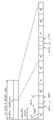
- Radio frame 7 shows a TDD radio frame structure in a 3GPP LTE system. This may be referred to Section 4.2 of 3GPP TS 36.211 V8.2.0 (2008-03) "Technical Specification Group Radio Access Network; Evolved Universal Terrestrial Radio Access (E-UTRA); Physical Channels and Modulation (Release 8)".
- One radio frame consists of two half-frames having a length of 10 ms and a length of 5 ms.
- One half frame also consists of five subframes having a length of 1 ms.
- One subframe is divided into two slots having a length of 0.5 ms.
- One subframe is designated as one of an uplink subframe (UL subframe), a downlink subframe (DL subframe), and a special subframe.
- One radio frame includes at least one uplink subframe and at least one downlink subframe.
- One slot includes a plurality of Orthogonal Frequency Division Multiplexing (OFDM) symbols in the time domain and a plurality of subcarriers in the frequency domain.
- the OFDM symbol is used to represent one symbol period since 3GPP LTE uses OFDMA in downlink, and may be called a different name according to a multiple access scheme.
- SC-FDMA when SC-FDMA is used as an uplink multiple access scheme, it may be referred to as an SC-FDMA symbol.
- a resource block (RB) includes a plurality of consecutive subcarriers in one slot in resource allocation units.
- the structure of the radio frame is merely an example. Accordingly, the number of subframes included in the radio frame, the number of slots included in the subframe, or the number of OFDM symbols included in the slot may be variously changed.
- 3GPP LTE defines that one slot includes 7 OFDM symbols in a normal cyclic prefix (CP), and one slot includes 6 OFDM symbols in an extended CP.
- CP normal cyclic prefix
- the special subframe is a specific period for separating the uplink and the downlink between the uplink subframe and the downlink subframe.
- At least one special subframe exists in one radio frame, and the special subframe includes a downlink pilot time slot (DwPTS), a guard period (GP), and an uplink pilot time slot (UpPTS).
- DwPTS is used for initial cell search, synchronization or channel estimation.
- UpPTS is used for channel estimation at the base station and synchronization of uplink transmission of the terminal.
- GP is a guard period for removing interference caused by the uplink due to the multipath delay of the downlink signal between the uplink and the downlink.
- Table 1 shows a structure of a configurable radio frame according to an arrangement of an uplink subframe and a downlink subframe in a 3GPP LTE TDD system.
- 'D' is a downlink subframe
- 'U' is an uplink subframe
- 'S' is a special subframe.
- the special subframe represents a switching point, that is, DwPTS + GP + UpPTS.
- Configurations 0 to 2 and 6 are configurations in which downlink and uplink are switched at a switching point period of 5 ms. At this time, the special subframe exists in both half frames.
- Configurations 3 to 5 are configurations in which downlink and uplink are switched at a switching point period of 10 ms. At this time, the special subframe exists only in the first half frame of the two half frames. DwPTSs of subframes 0, 5 and special subframes are always allocated for downlink transmission. In addition, the UpPTS of the special subframe and the subframe immediately after the special subframe are always allocated for uplink transmission.
- Table 2 shows a configuration method of DwPTS, GP, and UpPTS considered in 3GPP LTE system.
- T s means the sampling time and is calculated as 1 / (15000 * 2048) (sec).
- the special subframe has 9 combinations for the normal CP and 7 combinations for the extended CP.
- a guard period for subframe conversion is not necessary.
- a guard period is required. This is because each UE performs a timing advance (TA) to match uplink synchronization during uplink transmission. Therefore, if there is no guard interval, the interval in which the terminal receives the signal in downlink and the interval in which the terminal receives the signal in uplink may overlap.
- TA timing advance
- the overhead of the guard interval increases as the uplink subframe is frequently arranged after the downlink subframe. Therefore, in order to reduce the overhead of the guard interval, it is necessary to apply a technique of continuously arranging downlink subframes and then continuously arranging uplink subframes. For example, in the LTE system, one or two guard periods are arranged in ten subframes, and a downlink subframe or an uplink subframe is continuously arranged between the guard periods. In a cellular communication system in which a base station manages scheduling, when uplink subframes are continuously arranged, scheduling of uplink subframes is performed in a preceding downlink subframe.
- the wireless interface protocol of FIG. 8 horizontally consists of a physical layer, a data link layer, and a network layer, and vertically, a user plane for transmitting data information. And Control Plane for Signaling.
- the protocol layers of FIG. 8 are based on the lower three layers of the Open System Interconnection (OSI) reference model, which are well known in communication systems, and include L1 (first layer), L2 (second layer), and L3 (first layer). Three layers).
- OSI Open System Interconnection
- the physical layer which is the first layer, provides an information transfer service to an upper layer by using a physical channel.
- the physical layer is connected to the upper medium access control layer through a transport channel, and data between the medium access control layer and the physical layer moves through the transport channel. Then, data is moved between different physical layers, that is, between physical layers of a transmitting side and a receiving side through physical channels.
- MAC Medium access control
- RLC Radio link control layer
- the functionality of the RLC layer may be implemented as a functional block inside the MAC. In this case, the RLC layer may not exist.
- the PDCP layer of the second layer is a header compression that reduces the IP packet header size, which is relatively large and contains unnecessary control information, for efficient transmission in a low bandwidth wireless section when transmitting an IP packet such as IPv4 or IPv6. Compression) function.
- the radio resource control layer (hereinafter abbreviated as RRC) layer located at the bottom of the third layer is defined only in the control plane, and the configuration and resetting of radio bearers (abbreviated as RB) are performed. It is responsible for the control of logical channels, transport channels and physical channels in relation to configuration and release.
- RB means a service provided by the second layer for data transmission between the terminal and the UTRAN.
- a downlink transmission channel for transmitting data from a network to a UE includes a broadcast channel (BCH) for transmitting system information and a downlink shared channel (SCH) for transmitting user traffic or control messages.
- Traffic or control messages of a downlink multicast or broadcast service may be transmitted through a downlink SCH or may be transmitted through a separate downlink multicast channel (MCH).
- the uplink transmission channel for transmitting data from the terminal to the network includes a random access channel (RAC) for transmitting an initial control message and an uplink shared channel (SCH) for transmitting user traffic or control messages.
- RAC random access channel
- SCH uplink shared channel
- a downlink physical channel for transmitting information transmitted through a downlink channel through a radio section between a network and a terminal
- a physical broadcast channel (PBCH) for transmitting BCH information
- a physical multicast channel (PMCH) for transmitting MCH information
- Control information provided by the first layer and the second layer such as a physical downlink shared channel (PDSCH) for transmitting information of the PCH and the downlink SCH, and downlink or uplink radio resource allocation information (DL / UL Scheduling Grant).
- PDSCH physical downlink shared channel
- DL / UL Scheduling Grant downlink or uplink radio resource allocation information
- PDCCH also called a physical downlink control channel, or a DL L1 / L2 control channel
- a physical uplink shared channel (PUSCH) for transmitting uplink SCH information and a physical random access (PRACH) for transmitting RACH information are used as an uplink physical channel for transmitting information transmitted through an uplink transmission channel to a radio section between a network and a terminal.
- Channel Physical Uplink Control Channel
- PUCCH Physical Uplink Control Channel
- the terminal when the terminal needs uplink radio resources, the terminal may be allocated radio resources only when the terminal requests radio resources. If the terminal has a Physical Uplink Control Channel (PUCCH) radio resource for a scheduling request (SR) preset from the base station, the terminal may request a radio resource to the base station through the PUCCH, the base station Accordingly, an appropriate radio resource is allocated to the terminal, and the terminal transmits data to the base station using the radio resource.
- PUCCH Physical Uplink Control Channel
- SR scheduling request
- SR scheduling request
- sTTI short TTI
- the base station cannot perform scheduling to all terminals. For example, when an accident occurs in the vehicle communication, when the surrounding cars which detect the accident make a scheduling request to the base station at the same time, the base station cannot schedule all the cars at the same time.
- the base station it is necessary for the base station to distinguish the importance of information from the scheduling request step and to perform scheduling from the important information first.
- the most representative way to determine the importance of information is to utilize a Quality of Service (QoS) condition.
- QoS Quality of Service
- a base station knows QoS conditions of a service currently provided by each terminal, the scheduling priority may be determined according to the QoS when receiving a scheduling request from a plurality of terminals.
- each UE transmits a Logical Channel Group Identifier (LCGID) in which multiple QoSs are mapped in a Buffer Status Report (BSR) step to inform the base station of scheduling priority.
- LGID Logical Channel Group Identifier
- BSR Buffer Status Report
- the technique of classifying QoS when there is a scheduling request by allocating a plurality of scheduling request resources to a terminal has a disadvantage of increasing scheduling request resources allocated to the terminal.
- the scheduling request resource should be allocated to each terminal in a short period, and thus an increase in system overhead due to an increase in the scheduling request resource may be further highlighted.
- the base station may not allocate as many scheduling request resources as desired to each terminal. For example, in vehicle communication, since 15840 vehicles may exist at a radius of 1.6 km at an intersection of three highways of 10 lanes of round trip (Qualcomm, 3GPP S1-152275), the technique is difficult to apply.
- the technique of classifying the importance of information only according to QoS has a disadvantage in that duplicate information cannot be filtered out.
- all nearby vehicles that have detected the accident may request scheduling from the base station, and the vehicles all perform a scheduling request for accident notification having a high QoS.
- the base station does not need to schedule resources for all vehicles. If scheduling requests with high priority QoS on different paths are received at the same time, the base station needs to filter out duplicated information on the same path and perform scheduling on vehicles on different paths. Do. That is, if the importance of the information is similar, it is necessary to first schedule the non-overlapping information, and the base station can estimate whether the information overlaps based on the location of the terminal making the scheduling request.
- a method of estimating whether information is duplicated based on the location of a terminal there are a method of allocating scheduling request resources in consideration of the location of each terminal, and a method of creating a cluster for each region and setting a cluster head.
- the method of allocating scheduling request resources by reflecting the location of the UE has a disadvantage in that an additional scheduling request resource needs to be allocated to distinguish the locations. If the scheduling request resource is allocated to represent both the QoS and the location of the terminal, the overhead of the scheduling request resource is further increased.
- each terminal in the cluster senses and transmits sensing information to the cluster head, and the cluster head transmits a signal to the base station.
- This method has the disadvantage of increasing delay and increasing overhead of the cluster head.
- Another method is to sense only the cluster head in the cluster and transmit the corresponding information to the base station. This method has the disadvantage that the delay of signal transmission is reduced but blind spots are not detected.
- the signaling overhead is increased in the case of the mobile terminal because the cluster must be updated periodically and the cluster head is designated every time when each terminal moves.
- the present specification proposes a method of allocating scheduling request resources by reflecting location information of a terminal. Therefore, the present specification can be applied to all services that sense the surroundings and transmit the sensed information to the base station.
- the present specification divides the scheduling request resource into a first scheduling request resource and a second scheduling request resource having different resource allocation periods in order to allocate the scheduling request resource by reflecting the location information of the terminal, and proposes an operation of the terminal.
- the first scheduling request resource may correspond to a resource including the scheduling request resource and may also be called a first resource.
- the second scheduling request resource corresponds to a resource including the scheduling request resource and may also be referred to as a second resource.
- the scheduling request resource discussed herein is a logical resource.
- the logical scheduling request resource may be mapped to physically different resource blocks, resource elements, different spreading signals, different sequences, different preambles, different physical antennas, different logical antennas, and the like.
- the base station is located using PMI (Precoding Matrix Indicator) information or an uplink reference signal (for example, SRS (Sounding Reference Signal) or UL Uplink Demodulation-Reference Signal (DM-RS) of the LTE system transmitted by the UE to the base station). Can be estimated.
- PMI Precoding Matrix Indicator
- an uplink reference signal for example, SRS (Sounding Reference Signal) or UL Uplink Demodulation-Reference Signal (DM-RS) of the LTE system transmitted by the UE to the base station.
- SRS Sounding Reference Signal
- DM-RS UL Uplink Demodulation-Reference Signal
- the PMI of the present specification may correspond to a preferred analog (RF) beam index or an index of a preferred preamble (or reference signal).
- the PMI may correspond to a beam index or a corresponding antenna port index.
- the purpose of the algorithm is to allocate less resources for the scheduling request while keeping the probability of success of the scheduling request constant.
- the scheduling request resource is allocated by reflecting the location of the terminal. Advantages of reflecting the location of the terminal in the scheduling request resource are as follows.
- the scheduling request resource is insufficient as the number of terminals increases, but as the number of terminals increases, the number of terminals sensing the specific event when the number of terminals occurs increases. Therefore, when the number of terminals sensing a single event increases, even if the probability that each terminal successfully transmits a scheduling request decreases, the probability that the scheduling request for single event transmission is successfully transmitted to the base station may be kept constant.
- events occur in each region. Therefore, each region has a constant probability of successfully sending a scheduling request to the base station. The probability that the scheduling request is successfully sent to the base station can be kept constant.
- the base station should maintain the number of regions in the cell less than or equal to N.
- the base station is divided into different regions if the PMI is different, and the type of PMI transmitted by the terminal to the base station is M and M is larger than N.
- M PMIs must be mapped to N regions through quantization.
- One or more of the terminals (with PMI) located in a specific area allocate dedicated scheduling request resources that do not overlap with other terminals. This is to secure one or more independent scheduling request resources for each region.
- the terminal 1 and the terminal 3 are allocated the scheduling request resources, respectively, and the terminal 2 and the terminal 4 The same scheduling request resource is allocated.
- the terminal 1 and the danal 4 are allocated the scheduling request resources, respectively. 5 is allocated the same scheduling request resource.
- terminals in the same region are allocated to different scheduling request resources in preference to terminals in another region (different PMI).
- terminals of different regions are allocated to the same scheduling request resource. This is because the probability that the terminals in the corresponding region request scheduling at the same time is greater than the probability that the terminals in the other region request the scheduling at the same time.
- the terminals that have not been allocated the dedicated scheduling request resource may have an effect of allowing the base station to know this more than a certain probability even if an accident occurs in a region that the terminal allocated the dedicated scheduling request resource cannot sense.
- the terminal 1 and the terminal 2 should be allocated to different scheduling request resources.
- the terminal 1 and the terminal 3 are allocated to different scheduling request resources and the scheduling request resources are assigned to the terminal 2. Do not assign.
- terminals in the same region are preferentially allocated the same scheduling request resource. This is because the base station can receive the same information even if any of the terminals of the specific region is scheduled because the information in the same region is likely to be the same when the event occurs in the specific region.
- the terminal 1 and the terminal 2 are allocated to the same scheduling request resource, and the terminal 3 assigns another scheduling request resource. Assigned.
- the scheduling request resources are four
- the PMIs of the terminals 1 to 3 are the same and the PMIs of the terminals 4 to 6 are the same
- the terminal 1 and the terminal 4 are allocated a dedicated scheduling request resource
- the terminals 2 and 3 The common scheduling request resource is allocated and the terminals 5 and 6 are allocated the common scheduling request resource.
- the number of scheduling request resources is N in order to remove the terminal that is not allocated scheduling request resources under condition (1), the number of regions in the cell is N-1 or less.
- the scheduling request resources are three, the total number of PMIs is two, the PMIs of the terminals 1 to 3 are the same and the PMIs of the terminals 4 to 10 are the same, the scheduling request resources of the terminal 1 and the terminal 4 are different. And allocates terminals 2, 3, 5 to 10 to the same scheduling request resource.
- the scheduling request resource allocated to the terminals in common may be a resource for transmitting a preamble, such as a random access channel of the LTE system.
- condition (2) By reinforcing condition (2), terminals in the same region (the same PMI) are not allocated the same scheduling request resource. This has the effect of limiting the maximum number of terminals capable of scheduling requests according to the number of scheduling request resources. Applying condition (4) at the same time has the effect of reducing the collision probability of the scheduling request.
- the terminal 1 and the terminal 4 are assigned to different scheduling request resources.
- the terminal 2 and terminal 5 are allocated to the same scheduling request resource.
- the scheduling request resources are not allocated to the terminal 3 and the terminal 6 to 10.
- the base station When the base station receives a scheduling request from the common scheduling request resource (for example, the same preamble), the base station allocates the same scheduling request resource to an uplink resource to any of the terminals to which the common scheduling request resource has been allocated.
- the assigned terminals should be assigned different physical layer terminal identifiers (eg, C-RNTI (Cell-Radio Network Temporary Identifier)).
- UEs 1 to 3 are allocated the same scheduling request resource and UE 1 and UE 2 simultaneously perform the scheduling request. Since the base station does not know which one of the terminals 1 to 3 has requested scheduling, the base station may perform uplink scheduling to all three terminals (transmit uplink grant) or uplink scheduling to any terminal. Terminals 1 to 3 must have different physical layer terminal identifiers to determine whether the uplink scheduling signal transmitted by the base station is its own.
- the terminals allocated to the common scheduling request resource have a higher probability of not being allocated the resource when the scheduling request is transmitted.
- the scheduling request resource is divided into a first scheduling request resource and a second scheduling request resource, and a terminal allocated a common scheduling request resource in the first scheduling request resource allocates an additional scheduling request resource in the second scheduling request resource. Suggest a technique to receive.
- a dedicated scheduling request resource and a common scheduling request resource are allocated to the first scheduling request resource, and only a dedicated scheduling request resource is allocated to the second scheduling request resource.
- a method of allocating a scheduling request resource to a first scheduling request resource based on a location and allocating a scheduling request resource to a second scheduling request resource regardless of a location may be applied.
- FIG. 10 illustrates an example in which a first scheduling request resource and a second scheduling request resource are allocated according to an embodiment of the present specification.
- terminal 1 is allocated a dedicated scheduling request resource 1010, and terminals 2 to 4 are allocated a common scheduling request resource 1020.
- the terminals 2 to 4 are allocated the dedicated scheduling request resource 1030 from the second scheduling request resource, and the period of the second scheduling request resource is set to be three times longer than the period of the first scheduling request resource.
- the first scheduling request resource allocated by the terminal is a dedicated scheduling request resource allocated only to the terminal, it is not necessary to allocate an additional scheduling request resource to the terminal.
- a first scheduling request resource allocated by the terminal is a common scheduling request resource (for example, a random access channel) allocated in common, and thus a collision may occur, each terminal is allocated exclusively. Scheduling request resources are required.
- a terminal allocated with a scheduling request resource in the first scheduling request resource or the second scheduling request resource may apply the same operation method as that of the existing LTE.
- Terminals allocated with a common scheduling request resource in the first scheduling request resource and allocated with a dedicated scheduling request resource in the second scheduling request resource operate in the following manner.
- the terminal selects a resource for transmitting a scheduling request from among a first scheduling request resource and a second scheduling request resource. That is, both the first scheduling request resource and the second scheduling request resource are allocated or receive allocation information for both the first scheduling request resource and the second scheduling request resource, but the scheduling request is actually the first scheduling request resource and the second scheduling request resource.
- a scheduling request resource is transmitted in one selected resource. There are three ways to choose.
- the scheduling request resource is performed by using the resource closest to the point in time at which the traffic occurred among the first scheduling request resource and the second scheduling request resource.
- the scheduling request resource is performed using the second scheduling request resource.
- the scheduling request is performed using the second scheduling request resource.
- the scheduling request is performed using the first scheduling request resource.
- the base station informs the terminal of the type of the service performing the scheduling request using the first scheduling request resource and the type of the service performing the scheduling request using the second scheduling request resource.
- the terminal designates a resource to be used as a scheduling request resource among the first scheduling request resource and the second scheduling request resource according to the service based on the received information.
- the terminal determines that the base station has not received the scheduling request using the first scheduling request resource, it transmits the scheduling request using the second scheduling request resource afterwards for contention resolution.
- the order in which the terminal receives the signaling transmitted by the base station to allocate the first scheduling request resource and the second scheduling request resource to the terminal is 1) information on the first scheduling request resource broadcasted by the base station and the second scheduling request resource. 2)
- the base station is equivalent to receiving information on the first scheduling request resource and information on the second scheduling request resource transmitted by the terminal.
- the terminal receives information broadcast in the cell by the base station and receives period information on whether the first scheduling request resource and the second scheduling request resource exist, and the first scheduling request resource and the second scheduling request resource.
- each terminal receives information on a scheduling request resource allocated from the base station.
- Each terminal may be allocated a scheduling request resource from the first scheduling request resource and the second scheduling request resource. In addition, it receives from the base station what scheduling request resources are used for each service.
- the base station broadcasts information on the first scheduling request resource and the information on the second scheduling request resource, there is an effect of reducing signaling overhead for allocation of the scheduling request resource transmitted by the base station to each terminal.
- the base station Broadcasting Information about the first scheduling request resource and information about the second scheduling request resource
- information that may be included in the information is as follows.
- Resource allocation period is expressed as the number of subframes, the number of TTIs, or the number of symbols Can the common scheduling request resource be allocated? If the indicator is 0, it indicates that only dedicated scheduling request resources can be allocated from the first resource. 1 means that common scheduling request resource can be allocated.
- Uplink Reference Signal Transmission Period -Period in which the terminal transmits an uplink reference signal (eg SRS) to the base station to which the base station is allocated a location-based dedicated scheduling request resource so that the base station can track the location of the terminal; It may not be set.
- Information about the second scheduling request resource Time resource information Symbol (subframe) start point and symbol (subframe) count information or symbol (subframe) start and end points Frequency resource information
- Subcarrier start point and subcarrier count or subcarrier start point and end point Resource allocation cycle is expressed as the number of subframes, the number of TTIs, or the number of symbols
- the base station Since the first scheduling request resource allocates the scheduling request resource in a shorter period than the second scheduling request resource, the base station needs to transmit a signal to the terminal more frequently in order to allocate the scheduling request resource. Therefore, the base station may include some information about the first resource when transmitting the allocation information of the scheduling request resource in the second resource to any terminal, it is possible to reduce the signal overhead when allocating the scheduling request resource in the first resource .
- the terminal transmits information indicating which scheduling request resource to use according to the service type.
- the scheduling request resource in the first resource may correspond to the first scheduling request resource
- the scheduling request resource in the second resource may correspond to the second scheduling request resource.
- Information included in the signal for allocating the scheduling request resource in the second resource is as follows.
- Allocation indicator of the scheduling request resource in the first resource Indicator indicating that the scheduling request resource in the first resource has been allocated Indicator of how to perform scheduling request Information indicating to the terminal by the base station how to select a scheduling request resource in the method of selecting a scheduling request in 2.1.
- Allocation cycle of the scheduling request resource in the first resource Contains information indicating how often scheduling request resources are allocated Allocation indicator of the scheduling request resource in the second resource Indicator indicating that the scheduling request resource in the second resource has been allocated Allocation information of the scheduling request resource in the second resource Contains information indicating the time, frequency, and resource allocation period to which the scheduling request resource is allocated.
- Example 1 When information is generated, information about a service for transmitting a scheduling request to a first resource is transmitted.
- the service information is represented by a data radio bearer ID or QoS ID.
- services that transmit local information to the base station after sensing the local information may be instructed to perform a scheduling request with the first resource.
- Example 2 A service type indicator (eg, LCID of LTE) of a data radio bearer or MAC layer Transmit request delay time and request reliability information.
- the terminal designates which resource to perform the scheduling request resource in consideration of the information and the allocation period of the first resource and the second resource
- the information included in the signal for allocating the scheduling request resource in the first resource is as follows.
- Allocation information of the scheduling request resource in the first resource Contains information indicating the time and frequency to which the scheduling request resource is allocated
- the signal for allocating the scheduling request resource in the first resource may be transmitted as an L1, L2, or L3 signal.
- the first scheduling request resource PMI Based on each To the terminal Information broadcast by the base station if assigned
- the base station estimates the location of the terminal using the PMI
- the following technique may be applied to reduce the signaling overhead of L1, L2, or L3.
- the base station informs the terminal of the change pattern of the scheduling request resource according to the PMI change.
- the UE may change the scheduling request resource on its own, and thus has an advantage of semi-static notification of the region-based scheduling request resource. If the scheme is used for dynamically allocating a scheduling request resource, the signaling overhead of the physical layer can be reduced.
- the pattern information may be notified to the UEs in the cell in common through broadcast or multicast.
- the pattern information may inform each terminal when the base station establishes a connection with an arbitrary terminal or sets up a bearer for providing a new service.
- the pattern information may inform the terminal through a handover signal when the terminal performs handover.
- the pattern information may be notified through a paging signal when updating a tracking area (TA) unit when the terminal is in a disconnected state.
- the pattern information may simultaneously inform the terminal of uplink scheduling resources when the terminal performs data transmission in a disconnected state.
- the information in the following table may be broadcast in a cell.
- Table 6 shows an example in which all terminals having the same PMI are allocated the same scheduling request resource.
- the UE feeds back its PMI information to the base station and simultaneously changes its common scheduling request resource.
- the base station informs the terminal of the index of the scheduling request resource available for each PMI in common to each cell or for each terminal.
- Table 7 below shows an example of a case in which the number of PMI indexes is five and the number of scheduling request resource indexes is ten.
- Table 8 below shows an example in which the number of PMI indexes is five and the number of scheduling request resource indexes is twelve.
- Table 9 shows an example in which the number of PMI indexes is five and the number of scheduling request resource indexes is ten.
- Table 10 below shows an example in which the number of PMI indexes is five and the number of scheduling request resource indexes is twelve.
- the base station designates a scheduling request resource of the terminal according to the change of the terminal PMI. This has the effect of reducing the signaling overhead that the base station sends to the terminal.
- the base station may inform the terminal of one of 0 to 4 (scheduling request resource index), and then inform the total of 3 bits.
- the base station may inform the terminal which scheduling request resource has been allocated using a total of two bits.
- the scheduling request resource according to the PMI is not specified every PMI update, but has a specific period.
- the scheduling request resource may be allocated.
- the scheduling request resource may be updated for every L TTIs.
- the PMI may be grouped to map scheduling request resources. If the sensing coverage of the car is 100 meters but the beamforming change interval is 50 meters, the two PMIs can be bundled and managed.
- Table 11 shows an example of a case in which the dedicated scheduling request resource is not represented in a table and the base station does not overlap the dedicated scheduling resource through implementation. Table 11 below shows an example of a case where the number of PMI indexes is six and the number of scheduling request resource indexes is ten.
- Table 12 An example of a case where the dedicated scheduling request resource is represented in a table and the base station does not overlap the dedicated scheduling resources through implementation is shown in Table 12.
- Table 12 shows an example in which the number of PMI indexes is six and the number of scheduling request resource indexes is ten.
- the scheduling request pattern according to the PMI transmitted from the base station to the terminal varies according to the indicator for identifying the service.
- the base station transmits the terminal to the terminal according to a service indicator (for example, service classification indicator of the MAC layer such as QoS table index or LCID or information included in preamble and scheduling request).
- the scheduling request pattern changes according to the PMI.
- 11 is an exemplary diagram illustrating a process of receiving radio resource allocation through a scheduling request according to an embodiment of the present specification.
- the terminal when the terminal needs uplink radio resources, the terminal may be allocated radio resources only when the terminal requests radio resources. If the terminal has a Physical Uplink Control Channel (PUCCH) radio resource for a scheduling request (SR) preset from the base station, the terminal may request a radio resource to the base station through the PUCCH, the base station Accordingly, an appropriate radio resource is allocated to the terminal, and the terminal transmits data to the base station using the radio resource.
- PUCCH Physical Uplink Control Channel
- SR scheduling request
- FIG. 11 illustrates a process of receiving radio resources through a scheduling request according to an embodiment of the present specification.
- the first scheduling request (SR) resources and the second scheduling request (SR) resources are resources for the terminal to transmit the scheduling request.
- the first and second scheduling request resources may be classified as having different resource allocation periods, and the allocation period of the first scheduling request resource is shorter than the allocation period of the second scheduling request resource.
- the allocation period of the first scheduling request resource may be a time interval of the first scheduling request resource.
- the allocation period of the second scheduling request resource may be a time interval of the second scheduling request resource.
- a dedicated scheduling request resource and a common scheduling request resource may be allocated, and in the second scheduling request resource, a dedicated scheduling request resource may be allocated.
- the first scheduling request resource has a possibility of allocating a common scheduling request resource.
- the UE periodically transmits a channel quality indicator (CQI), a precoding matrix indicator (PMI), and a sounding reference signal (SRS) to the base station.
- CQI channel quality indicator
- PMI precoding matrix indicator
- SRS sounding reference signal
- the base station can estimate the location of the terminal through the PMI information.
- the PMI information includes a PMI index.
- a common scheduling request resource or a dedicated scheduling request resource is arranged according to the PMI. That is, the base station informs the terminal of the change pattern of the scheduling request resource according to the PMI change.
- the base station broadcasts information on the first scheduling request resource and the second scheduling request resource to the terminal. Since the information about the first and second scheduling request resources that are broadcast is delivered cell-specifically, the terminals in the cell mainly receive information about the region of the scheduling request resources.
- the information about the broadcasted first scheduling request resource includes a first indicator indicating whether a common scheduling request resource is allocated in the first scheduling request resource.
- the information on the broadcasted first scheduling request resource may further include a period in which the terminal feeds back the PMI to the base station and a period in which the terminal transmits the SRS to the base station.
- SIB system information block
- the base station may allocate the same first scheduling request resource to different terminals having different temporary identifiers.
- the common scheduling request resource is allocated from the first scheduling request resource, and if the first indicator does not indicate the predetermined value, the common scheduling request resource is not allocated from the first scheduling request resource. Only dedicated scheduling request resources are allocated.
- the base station transmits information on the first scheduling request resource and the second scheduling request resource that is specifically transmitted to the terminal to the specified terminal.
- the specified terminal since the information about the first and second scheduling request resources is transmitted to the terminal, the specified terminal receives the more specific information about the scheduling request resources.
- the information on the second scheduling request resource, which is specifically transmitted to the terminal may be determined in the second scheduling request resource if the common scheduling request resource is allocated from the first scheduling request resource (the first indicator indicates a predetermined value).
- a second indicator indicating that the resource is allocated.
- the terminal may receive allocation information indicating that the common scheduling request resource is allocated in the first scheduling request resource and allocation information indicating that the dedicated scheduling request resource is allocated in the second scheduling request resource according to the second indicator.
- the second indicator may further indicate that a dedicated scheduling request resource is not allocated in the second scheduling request resource if the dedicated scheduling request resource is allocated in the first scheduling request resource (as the first indicator does not indicate a predetermined value). It may be. This is because it is not necessary to allocate the dedicated scheduling request resource to the second scheduling request resource since the dedicated scheduling request resource for the specific terminal is already allocated in the first scheduling request resource.
- the terminal receives information on the first and second scheduling request resources that are specifically transmitted through the terminal through a radio resource control (RRC) or a physical downlink control channel (PDCCH).
- RRC radio resource control
- PDCH physical downlink control channel
- step S1140 the terminal based on the information about the first and second scheduling request resources broadcast and the information about the first and second scheduling request resources specifically transmitted to the terminal, the first scheduling request resource and the second scheduling. Select one of the request resources.
- the terminal receives allocation information for both the first scheduling request resource and the second scheduling request resource, but actually selects one resource for transmitting the scheduling request.
- the terminal selects a resource for transmitting the scheduling request from the first scheduling request resource and the second scheduling request resource.
- the third indicator indicating how to select the scheduling request resource is included in the information on the second scheduling request resource that is specifically transmitted to the terminal.
- a method of selecting a scheduling request resource is firstly a method of selecting a second scheduling request resource if the first scheduling request resource and the second scheduling request resource are in the same subframe.
- the second scheduling request resource is selected when the second scheduling request resource exists within the maximum scheduling request delay time, and the first scheduling when the second scheduling request resource does not exist within the maximum scheduling request delay time.
- the requesting resource is selected.
- information on a service for performing a scheduling request using the first and second scheduling request resources includes a radio bearer identifier (ID) or a quality of service identifier (QoS).
- ID radio bearer identifier
- QoS quality of service identifier
- step S1150 the terminal transmits a scheduling request through the selected resource.
- the base station transmits an uplink grant (or a control signal for uplink resource allocation) according to a scheduling request of the terminal and allocates radio resources for transmitting the uplink data by the terminal.
- the base station may transmit an uplink grant (or a control signal for uplink resource allocation) to all or some of the terminals allocated with the first scheduling request resource.
- FIG. 12 is a flowchart illustrating a procedure for transmitting a scheduling request by a terminal according to an embodiment of the present specification.
- the first scheduling request (SR) resource and the second scheduling request (SR) resource are resources for transmitting a scheduling request by the terminal.
- the first and second scheduling request resources may be classified as having different resource allocation periods, and the allocation period of the first scheduling request resource is shorter than the allocation period of the second scheduling request resource.
- a dedicated scheduling request resource and a common scheduling request resource may be allocated, and in the second scheduling request resource, a dedicated scheduling request resource may be allocated.
- the first scheduling request resource has a possibility of allocating a common scheduling request resource.
- step S1210 the terminal receives information about the first scheduling request resource and the second scheduling request resource broadcast from the base station. Since the information about the first and second scheduling request resources that are broadcast is delivered cell-specifically, the terminals in the cell mainly receive information about the region of the scheduling request resources.
- the information about the broadcasted first scheduling request resource includes a first indicator indicating whether a common scheduling request resource is allocated in the first scheduling request resource.
- the terminal receives information on the first scheduling request resource and the second scheduling request resource transmitted from the base station to the terminal specific.
- the specified terminal since the information about the first and second scheduling request resources is transmitted to the terminal, the specified terminal receives the more specific information about the scheduling request resources.
- the information on the second scheduling request resource, which is specifically transmitted to the terminal may be determined in the second scheduling request resource if the common scheduling request resource is allocated from the first scheduling request resource (the first indicator indicates a predetermined value).
- a second indicator indicating that the resource is allocated.
- the terminal may receive allocation information indicating that the common scheduling request resource is allocated in the first scheduling request resource and allocation information indicating that the dedicated scheduling request resource is allocated in the second scheduling request resource according to the second indicator.
- step S1220 the terminal based on the information on the first and second scheduling request resources broadcast and the information on the first and second scheduling request resources specifically transmitted, the first scheduling request resource and the second scheduling. Select one of the request resources.
- the terminal receives allocation information for both the first scheduling request resource and the second scheduling request resource, but actually selects one resource for transmitting the scheduling request.
- step S1230 the terminal transmits a scheduling request through the selected resource.
- FIG. 13 is a block diagram illustrating a device in which an embodiment of the present specification is implemented.
- the wireless device 1300 may include a processor 1310, a memory 1320, and a radio frequency (RF) unit 1330.
- the processor 1310 may be configured to implement the above-described functions, procedures, and methods. Layers of a radio interface protocol may be implemented in a processor. The processor 1310 may perform a procedure for driving the above-described operation.
- the memory 1320 is operatively connected to the processor 1310, and the RF unit 1330 is operatively connected to the processor 1310.
- the processor 1310 may include an application-specific integrated circuit (ASIC), another chipset, a logic circuit, and / or a data processing device.
- the memory 1320 may include read-only memory (ROM), random access memory (RAM), flash memory, memory card, storage medium, and / or other storage device.
- the RF unit 1330 may include a baseband circuit for processing a radio signal.
- the above-described technique may be implemented as a module (process, function, etc.) for performing the above-described function.
- the module may be stored in the memory 1320 and executed by the processor 1310.
- the memory 1320 may be inside or outside the processor 1310 and may be connected to the processor 1310 through various well-known means.
Landscapes
- Engineering & Computer Science (AREA)
- Signal Processing (AREA)
- Computer Networks & Wireless Communication (AREA)
- Mobile Radio Communication Systems (AREA)
Abstract
무선 통신 시스템에서 스케줄링 요청을 전송하는 방법 및 기기가 제공된다. 구체적으로, 단말은 기지국으로부터 브로드캐스트되는 제1 및 제2 스케줄링 요청 자원에 대한 정보를 수신한다. 단말은 기지국으로부터 단말 특정하게 전달되는 제1 및 제2 스케줄링 요청 자원에 대한 정보를 수신한다. 단말은 상기 정보를 기반으로 상기 제1 스케줄링 요청 자원 및 상기 제2 스케줄링 요청 자원 중 어느 하나의 자원을 선택한다. 단말은 선택된 자원을 통해 스케줄링 요청을 전송한다.
Description
본 명세서는 무선 통신에 관한 것으로, 보다 상세하게는 무선 통신 시스템에서 스케줄링 요청을 전송하는 방법 및 이를 사용한 기기에 관한 것이다.
무선 통신 시스템은 음성이나 데이터 등과 같은 다양한 종류의 통신 서비스를 제공하기 위해 광범위하게 전개되고 있다. 무선 통신 시스템의 목적은 다수의 단말이 위치와 이동성에 관계없이 신뢰할 수 있는(reliable) 통신을 할 수 있도록 하는 것이다.
일반적으로 무선 통신 시스템은 가용한 무선 자원을 공유하여 다수의 단말과의 통신을 지원할 수 있는 다중 접속(multiple access) 시스템이다. 무선 자원의 예로는 시간, 주파수, 코드, 전송 파워 등이 있다. 다중 접속 시스템의 예들로는 TDMA(time division multiple access) 시스템, CDMA(code division multiple access) 시스템, FDMA(frequency division multiple access) 시스템, OFDMA(orthogonal frequency division multiple access) 시스템, SC-FDMA(single carrier frequency division multiple access) 시스템 등이 있다.
기지국은 스케줄링을 통해 셀 내 단말들마다 무선 자원을 적절히 할당한다. 단말은 할당 받은 무선 자원을 이용하여 기지국에게 제어정보를 전송하거나, 사용자 데이터를 전송할 수 있다. 그런데, 제어정보 전송 방식과 사용자 데이터 전송 방식은 다를 수 있다. 또, 제어정보를 위한 무선 자원 할당 방식과 사용자 데이터를 위한 무선 자원 할당 방식 역시 다를 수 있다. 따라서, 제어정보를 위한 무선 자원과 사용자 데이터를 위한 무선 자원은 서로 다를 수 있다. 기지국은 제어정보를 위해 예약된 무선 자원과 사용자 데이터를 위해 예약된 무선 자원을 구분하여 관리할 수 있다.
3GPP LTE 시스템에서는 제어정보나 사용자 데이터가 하나의 서브프레임 상에서 전송되는 데 걸리는 시간을 TTI(transmission time interval)라 한다. 일반적으로 하나의 서브프레임의 길이는 1ms이다. 하지만, 보다 높은 데이터 레이트와 빠른 채널 환경 변화에 대응하기 위한 차세대 무선 통신 시스템에서는 사용자 평면(user plane)상에서의 레이턴시(latency)를 1ms가 되도록 달성하고자 한다. 즉, 1ms 길이의 TTI는 차세대 무선 통신 시스템에서의 낮은 레이턴시 요구(low latency requirement)에 적합하지 않는 구조를 가진다. 따라서, 기존의 TTI를 더 작은 단위로 나눈 short TTI를 제어하여 보다 낮은 레이턴시를 만족하기 위한 무선 자원 구조를 배치시키는 방법이 필요하다.
본 명세서는 무선 통신 시스템에서 스케줄링 요청을 전송하는 방법 및 장치를 제공한다.
본 명세서는 무선 통신 시스템에서 스케줄링 요청을 전송하는 방법을 제안한다.
먼저, 용어를 정리하면, 제1 스케줄링 요청(SR) 자원 및 제2 스케줄링 요청(SR) 자원은 단말이 스케줄링 요청을 전송하기 위한 자원이다. 제1 및 제2 스케줄링 요청 자원은 서로 다른 자원 할당 주기를 가지는 것으로 구분할 수 있는데, 제1 스케줄링 요청 자원의 할당 주기가 제2 스케줄링 요청 자원의 할당 주기보다 짧다. 제1 스케줄링 요청 자원에서는 전용 스케줄링 요청 자원과 공통 스케줄링 요청 자원이 할당되고, 제2 스케줄링 요청 자원에서는 전용 스케줄링 요청 자원이 할당될 수 있다. 다시 말하면, 제1 스케줄링 요청 자원에서는 공통 스케줄링 요청 자원이 할당될 가능성을 가지고 있다.
먼저, 단말은 기지국으로 CQI(Channel Quality Indicator), PMI(Precoding Matrix Indicator) 및 SRS(Sounding Reference Signal)를 주기적으로 전송한다. 기지국은 이러한 PMI 정보를 통해 단말의 위치를 추정할 수 있다. 여기서, PMI 정보는 PMI 인덱스를 포함한다. 상기 PMI에 따라 공통 스케줄링 요청 자원 또는 전용 스케줄링 요청 자원이 배치된다. 즉, 기지국은 PMI 변화에 따라 스케줄링 요청 자원의 변화 패턴을 단말에게 알려준다.
단말은 기지국으로부터 브로드캐스트되는 제1 스케줄링 요청 자원 및 제2 스케줄링 요청 자원에 대한 정보를 수신한다. 브로드캐스트되는 제1 및 제2 스케줄링 요청 자원에 대한 정보는 셀 특정(cell-specific)하게 전달되므로, 셀 내의 단말들은 주로 스케줄링 요청 자원의 영역에 대한 정보를 수신하게 된다. 브로드캐스트되는 제1 스케줄링 요청 자원에 대한 정보는 제1 스케줄링 요청 자원에서 공통 스케줄링 요청 자원이 할당되는지 여부를 지시하는 제1 지시자를 포함한다. 또한, 브로드캐스트되는 제1 스케줄링 요청 자원에 대한 정보는 단말이 기지국에 PMI를 피드백하는 주기 및 단말이 기지국에 SRS를 전송하는 주기를 더 포함할 수도 있다. 또한, 브로드캐스트되는 제1 및 제2 스케줄링 요청 자원에 대한 정보는 SIB(System Information Block)를 통해 수신된다.
상기 제1 지시자가 기지정된 값을 지시하면 제1 스케줄링 요청 자원에서 공통 스케줄링 요청 자원이 할당되고, 상기 제1 지시자가 기지정된 값을 지시하지 않으면 제1 스케줄링 요청 자원에서 공통 스케줄링 요청 자원이 할당되지 않고 전용 스케줄링 요청 자원만 할당된다.
단말은 기지국으로부터 단말 특정하게 전달되는 제1 스케줄링 요청 자원 및 제2 스케줄링 요청 자원에 대한 정보를 수신한다. 이때는, 제1 및 제2 스케줄링 요청 자원에 대한 정보가 단말 특정하게 전달되므로, 특정된 단말은 스케줄링 요청 자원에 대한 보다 구체적인 정보를 수신하게 된다. 단말 특정하게 전달되는 제2 스케줄링 요청 자원에 대한 정보는 상기 제1 스케줄링 요청 자원에서 상기 공통 스케줄링 요청 자원이 할당된다면(제1 지시자가 기지정된 값을 지시하여) 제2 스케줄링 요청 자원에서 전용 스케줄링 요청 자원이 할당되는 것을 지시하는 제2 지시자를 포함한다. 이때, 단말은 제2 지시자에 의하면 제1 스케줄링 요청 자원에서는 공통 스케줄링 요청 자원이 할당되었다는 할당 정보와 제2 스케줄링 요청 자원에서는 전용 스케줄링 요청 자원이 할당되었다는 할당 정보를 수신할 수 있다.
또한, 제2 지시자는 제1 스케줄링 요청 자원에서 전용 스케줄링 요청 자원이 할당된다면(제1 지시자가 기지정된 값을 지시하지 않아서) 제2 스케줄링 요청 자원에서 전용 스케줄링 요청 자원이 할당되지 않는 것을 더 지시할 수도 있다. 이미 제1 스케줄링 요청 자원에서 특정 단말에 대한 전용 스케줄링 요청 자원이 할당되었으므로 제2 스케줄링 요청 자원까지 전용 스케줄링 요청 자원을 할당할 필요는 없기 때문이다.
단말은 단말 특정하게 전달되는 제1 및 제2 스케줄링 요청 자원에 대한 정보를 RRC(Radio Resource Control) 또는 PDCCH(Physical Downlink Control Channel)를 통해 수신한다.
단말은 브로드캐스트되는 제1 및 제2 스케줄링 요청 자원에 대한 정보와 단말 특정하게 전달되는 제1 및 제2 스케줄링 요청 자원에 대한 정보를 기반으로, 제1 스케줄링 요청 자원 및 제2 스케줄링 요청 자원 중 어느 하나의 자원을 선택한다. 단말은 제1 스케줄링 요청 자원 및 제2 스케줄링 요청 자원 둘 다에 대한 할당 정보를 수신하나, 실제로 스케줄링 요청을 전송할 하나의 자원을 선택하게 된다.
단말이 스케줄링 요청을 전송할 자원을 제1 스케줄링 요청 자원 및 제2 스케줄링 요청 자원 중에서 선택하는 방법은 총 3가지가 있다. 이러한 스케줄링 요청 자원을 선택하는 방법을 지시하는 제3 지시자는 상기 단말 특정하게 전달되는 제2 스케줄링 요청 자원에 대한 정보에 포함된다.
스케줄링 요청 자원을 선택하는 방법은 첫째로, 제1 스케줄링 요청 자원 및 제2 스케줄링 요청 자원이 동일한 서브프레임 내에 있다면, 제2 스케줄링 요청 자원이 선택되는 방법이 있다. 둘째로, 최대 스케줄링 요청 지연 시간 내에 상기 제2 스케줄링 요청 자원이 존재하는 경우 상기 제2 스케줄링 요청 자원이 선택되고, 최대 스케줄링 요청 지연 시간 내에 상기 제2 스케줄링 요청 자원이 존재하지 않는 경우 상기 제1 스케줄링 요청 자원이 선택되는 방법이 있다. 셋째로, 상기 제1 및 제2 스케줄링 요청 자원을 사용하여 스케줄링 요청을 수행하는 서비스에 대한 정보에 따라, 상기 제1 SR 자원 및 상기 제2 SR 자원 중 어느 하나의 자원이 선택되는 방법이 있다.
세 번째 방법에서, 제1 및 제2 스케줄링 요청 자원을 사용하여 스케줄링 요청을 수행하는 서비스에 대한 정보는 무선 베어러 ID(Radio Bearer Identifier) 또는 QoS ID(Quality of Service Identifier)를 포함한다.
단말은 선택된 자원을 통해 스케줄링 요청을 전송한다.
기지국은 단말의 스케줄링 요청에 따라 상향링크 그랜트(uplink grant)를 전송하여 단말이 상향링크 데이터를 전송하기 위한 무선자원을 할당한다.
또한, 본 명세서는 무선 통신 시스템에서 스케줄링 요청을 전송하는 단말(장치)을 제안한다.
먼저 용어를 정리하면, 제1 스케줄링 요청(SR) 자원 및 제2 스케줄링 요청(SR) 자원은 단말이 스케줄링 요청을 전송하기 위한 자원이다. 제1 및 제2 스케줄링 요청 자원은 서로 다른 자원 할당 주기를 가지는 것으로 구분할 수 있는데, 제1 스케줄링 요청 자원의 할당 주기가 제2 스케줄링 요청 자원의 할당 주기보다 짧다. 제1 스케줄링 요청 자원에서는 전용 스케줄링 요청 자원과 공통 스케줄링 요청 자원이 할당되고, 제2 스케줄링 요청 자원에서는 전용 스케줄링 요청 자원이 할당될 수 있다. 다시 말하면, 제1 스케줄링 요청 자원에서는 공통 스케줄링 요청 자원이 할당될 가능성을 가지고 있다.
상기 단말은 무선신호를 전송 및 수신하는 RF(radio frequency)부와 상기 RF부에 연결되는 프로세서를 포함한다.
프로세서는 기지국으로부터 브로드캐스트되는 제1 스케줄링 요청 자원 및 제2 스케줄링 요청 자원에 대한 정보를 수신한다. 브로드캐스트되는 제1 및 제2 스케줄링 요청 자원에 대한 정보는 셀 특정(cell-specific)하게 전달되므로, 셀 내의 단말들은 주로 스케줄링 요청 자원의 영역에 대한 정보를 수신하게 된다. 브로드캐스트되는 제1 스케줄링 요청 자원에 대한 정보는 제1 스케줄링 요청 자원에서 공통 스케줄링 요청 자원이 할당되는지 여부를 지시하는 제1 지시자를 포함한다.
프로세서는 기지국으로부터 단말 특정하게 전달되는 제1 스케줄링 요청 자원 및 제2 스케줄링 요청 자원에 대한 정보를 수신한다. 이때는, 제1 및 제2 스케줄링 요청 자원에 대한 정보가 단말 특정하게 전달되므로, 특정된 단말은 스케줄링 요청 자원에 대한 보다 구체적인 정보를 수신하게 된다. 단말 특정하게 전달되는 제2 스케줄링 요청 자원에 대한 정보는 상기 제1 스케줄링 요청 자원에서 상기 공통 스케줄링 요청 자원이 할당된다면(제1 지시자가 기지정된 값을 지시하여) 제2 스케줄링 요청 자원에서 전용 스케줄링 요청 자원이 할당되는 것을 지시하는 제2 지시자를 포함한다. 이때, 단말은 제2 지시자에 의하면 제1 스케줄링 요청 자원에서는 공통 스케줄링 요청 자원이 할당되었다는 할당 정보와 제2 스케줄링 요청 자원에서는 전용 스케줄링 요청 자원이 할당되었다는 할당 정보를 수신할 수 있다.
프로세서는 브로드캐스트되는 제1 및 제2 스케줄링 요청 자원에 대한 정보와 단말 특정하게 전달되는 제1 및 제2 스케줄링 요청 자원에 대한 정보를 기반으로, 제1 스케줄링 요청 자원 및 제2 스케줄링 요청 자원 중 어느 하나의 자원을 선택한다. 단말은 제1 스케줄링 요청 자원 및 제2 스케줄링 요청 자원 둘 다에 대한 할당 정보를 수신하나, 실제로 스케줄링 요청을 전송할 하나의 자원을 선택하게 된다.
프로세서는 단말은 선택된 자원을 통해 스케줄링 요청을 전송한다.
본 명세서에서 제안하는 기법을 적용하면 기지국이 동시 다발적으로 스케줄링 요청을 수신한 경우에도 각 지역 별로 스케줄링 요청을 성공적으로 수신할 확률을 일정하게 유지하는 효과가 있다. 일반적으로 센싱을 통해 사건의 발생 여부를 파악하고 해당 정보를 전송하는 단말들의 경우에는 서로 다른 지역에서 동시 다발적으로 스케줄링을 요청하는 경우보다 동일한 지역에서 동시 다발적으로 스케줄링을 요청하는 경우가 많다. 따라서, 제안하는 기법을 이용하면 각 지역 별로 스케줄링 요청을 수신할 확률을 증가시키는 효과가 있다.
도 1은 3GPP LTE에서 무선 프레임의 구조를 나타낸다.
도 2는 3GPP LTE에서 하나의 상향링크 슬롯에 대한 자원 그리드(resource grid)를 나타낸 예시도이다.
도 3은 3GPP LTE에서 하향링크 서브프레임의 구조의 예를 나타낸다.
도 4는 서브프레임과 특수 심벌을 포함하는 무선 프레임의 구조를 나타낸다.
도 5는 특수 심벌이 앞부분에 연속적으로 배치된 무선 프레임 구조의 일례를 나타낸다.
도 6은 특수 심벌이 뒷부분에 연속적으로 배치된 무선 프레임 구조의 일례를 나타낸다.
도 7은 3GPP LTE 시스템에서 TDD 무선 프레임(radio frame) 구조를 나타낸다.
도 8은 단말과 E-UTRAN 사이의 무선인터페이스 프로토콜의 제어평면 구조를 나타낸다.
도 9는 단말과 E-UTRAN 사이의 무선인터페이스 프로토콜의 사용자평면 구조를 나타낸다.
도 10은 본 명세서의 실시예에 따른 제1 스케줄링 요청 자원 및 제2 스케줄링 요청 자원이 할당되는 일례를 나타낸다.
도 11은 본 명세서의 실시예에 따른 스케줄링 요청을 통해 무선자원을 할당받는 과정을 나타낸 예시도이다.
도 12는 본 명세서의 실시예에 따른 단말이 스케줄링 요청을 전송하는 절차를 나타낸 흐름도이다.
도 13은 본 명세서의 실시예가 구현되는 기기를 나타낸 블록도이다.
이하의 기술은 CDMA(code division multiple access), FDMA(frequency division multiple access), TDMA(time division multiple access), OFDMA(orthogonal frequency division multiple access), SC-FDMA(single carrier-frequency division multiple access) 등과 같은 다양한 무선 통신 시스템에 사용될 수 있다. CDMA는 UTRA(Universal Terrestrial Radio Access)나 CDMA2000과 같은 무선 기술(radio technology)로 구현될 수 있다. TDMA는 GSM(Global System for Mobile communications)/GPRS(General Packet Radio Service)/EDGE(Enhanced Data Rates for GSM Evolution)와 같은 무선 기술로 구현될 수 있다. OFDMA는 IEEE 802.11 (Wi-Fi), IEEE 802.16 (WiMAX), IEEE 802-20, E-UTRA(Evolved UTRA) 등과 같은 무선 기술로 구현될 수 있다. UTRA는 UMTS(Universal Mobile Telecommunications System)의 일부이다. 3GPP(3rd Generation Partnership Project) LTE(long term evolution)는 E-UTRA를 사용하는 E-UMTS(Evolved UMTS)의 일부로써, 하향링크에서 OFDMA를 채용하고 상향링크에서 SC-FDMA를 채용한다.
설명을 명확하게 하기 위해, 3GPP LTE를 위주로 기술하지만 본 발명의 기술적 사상이 이에 제한되는 것은 아니다.
도 1은 3GPP LTE에서 무선 프레임의 구조를 나타낸다.
도 1을 참조하면, 무선 프레임(radio frame)은 10개의 서브프레임(subframe)으로 구성되고, 하나의 서브프레임은 2개의 슬롯(slot)으로 구성된다. 무선 프레임 내 슬롯은 0부터 19까지 슬롯 번호가 매겨진다. 하나의 서브프레임이 전송되는 데 걸리는 시간을 TTI(transmission time interval)라 한다. TTI는 데이터 전송을 위한 스케줄링 단위라 할 수 있다. 예를 들어, 하나의 무선 프레임의 길이는 10ms이고, 하나의 서브프레임의 길이는 1ms이고, 하나의 슬롯의 길이는 0.5ms 일 수 있다.
무선 프레임의 구조는 예시에 불과하고, 무선 프레임에 포함되는 서브프레임의 수 또는 서브프레임에 포함되는 슬롯의 수 등은 다양하게 변경될 수 있다.
도 2는 3GPP LTE에서 하나의 상향링크 슬롯에 대한 자원 그리드(resource grid)를 나타낸 예시도이다.
도 2를 참조하면, 상향링크 슬롯은 시간 영역(time domain)에서 복수의 SC-FDMA 심벌을 포함하고, 주파수 영역(frequency domain)에서 Nul 자원블록(Resource Block, RB)을 포함한다. SC-FDMA 심벌은 하나의 심벌 구간(symbol period)을 표현하기 위한 것으로, 시스템에 따라 OFDMA 심벌 또는 심벌 구간이라고 할 수 있다. 자원블록은 자원 할당 단위로 주파수 영역에서 복수의 부반송파를 포함한다. 상향링크 슬롯에 포함되는 자원블록의 수 Nul은 셀에서 설정되는 상향링크 전송 대역폭(bandwidth)에 종속한다. 상향링크 전송 대역폭은 시스템 정보(system information)이다. 단말은 시스템 정보를 획득하여 Nul을 알 수 있다.
자원 그리드 상의 각 요소(element)를 자원요소(resource element)라 한다. 자원 그리드 상의 자원요소는 슬롯 내 인덱스 쌍(pair) (k, ℓ)에 의해 식별될 수 있다. 여기서, k(k=0,...,Nul×12-1)는 주파수 영역 내 부반송파 인덱스이고, ℓ(ℓ=0,...,6)은 시간 영역 내 SC-FDMA 심벌 인덱스이다.
여기서, 하나의 자원블록은 시간 영역에서 7 SC-FDMA 심벌, 주파수 영역에서 12 부반송파로 구성되는 7×12 자원요소를 포함하는 것을 예시적으로 기술하나, 자원블록 내 부반송파의 수와 SC-FDMA 심벌의 수는 이에 제한되는 것은 아니다. 자원블록이 포함하는 SC-FDMA 심벌의 수 또는 부반송파의 수는 다양하게 변경될 수 있다. SC-FDMA 심벌의 수는 CP(cyclic prefix)의 길이에 따라 변경될 수 있다. 예를 들어, 노멀(normal) CP의 경우 SC-FDMA 심벌의 수는 7이고, 확장된(extended) CP의 경우 SC-FDMA 심벌의 수는 6이다.
도 2의 3GPP LTE에서 하나의 상향링크 슬롯에 대한 자원 그리드는 하향링크 슬롯에 대한 자원 그리드에도 적용될 수 있다. 다만, 하향링크 슬롯은 시간 영역에서 복수의 OFDM(orthogonal frequency division multiplexing) 심벌을 포함한다.
도 3은 3GPP LTE에서 하향링크 서브프레임의 구조의 예를 나타낸다.
도 3을 참조하면, 하향링크 서브프레임은 2개의 연속적인(contiguous) 슬롯을 포함한다. 하향링크 서브프레임 내의 제1 슬롯의 앞선 최대 3 OFDM 심벌들이 PDCCH(physical downlink control channel)가 할당되는 제어영역(control region)이고, 나머지 OFDM 심벌들은 PDSCH(physical downlink shared channel)가 할당되는 데이터 영역(data region)이 된다. 제어영역에는 PDCCH 이외에도 PCFICH(physical control format indicator channel), PHICH(physical hybrid-ARQ indicator channel) 등의 제어채널이 할당될 수 있다. 여기서, 제어영역이 3 OFDM 심벌을 포함하는 것은 예시에 불과하다. 서브프레임 내 제어영역이 포함하는 OFDM 심벌의 수는 PCFICH를 통해 알 수 있다. PHICH는 상향링크 데이터 전송의 응답으로 HARQ(hybrid automatic repeat request) ACK(acknowledgement)/NACK(not-acknowledgement) 정보를 나른다.
PDCCH는 PDSCH 상의 하향링크 전송의 자원 할당을 알려주는 하향링크 그랜트를 나를 수 있다. 단말은 PDCCH를 통해 전송되는 제어정보를 디코딩하여 PDSCH를 통해 전송되는 하향링크 사용자 데이터를 읽을 수 있다. 또한, PDCCH는 단말에게 PUSCH(physical uplink shared channel) 스케줄링을 위해 사용되는 제어정보를 나를 수 있다. PUSCH 스케줄링을 위해 사용되는 제어정보는 상향링크 전송의 자원 할당을 알려주는 상향링크 그랜트이다.
제어영역은 복수의 CCE(control channel elements)들의 집합으로 구성된다. PDCCH는 하나 또는 몇몇 연속적인 CCE의 집단(aggregation) 상으로 전송된다. CCE는 복수의 자원요소 그룹(resource element group)에 대응된다. 자원요소 그룹은 자원요소로의 제어채널 맵핑을 정의하기 위해 사용된다. 하향링크 서브프레임에서 CCE의 총 수가 Ncce라면, CCE는 0부터 Ncce,k-1까지 CCE 인덱스가 매겨진다. 서브프레임마다 서브프레임 내 제어영역이 포함하는 OFDM 심벌의 수가 변할 수 있기 때문에, 서브프레임 내 CCE의 총 수 역시 서브프레임마다 변할 수 있다.
이하에서는, N(>=1)개의 OFDM 심벌들로 구성된 서브프레임을 정의하고, M(>=0)개의 서브프레임과 제어 물리 신호 또는 제어 정보 전송 채널을 위한 P(>=0)개의 특수 심벌(special symbol; s-symbol)들을 묶은 임의의 무선 프레임 구조를 기술한다. 이는 도 1에서 예시된 14개의 연속된 OFDM 심벌들이 하나의 서브프레임이 되고, 10개의 서브프레임이 하나의 무선 프레임 구조를 갖는 것과는 다르게 임의로 설계한 무선 프레임 구조를 나타낸다.
서브프레임에서는 데이터, 제어 물리 신호, 제어 정보의 전송 등이 가능하며, 특수 심벌에서는 데이터를 제외한 제어 물리 신호와 제어 정보의 전송이 가능하다. 이러한 시구간 자원 전송 구조는 단말 단위로 지정하거나 셀 또는 시스템 전체 단말에 대해 공통적으로 적용되도록 지정될 수 있다. 이와 동시에 시간 또는 주파수 대역(서브밴드)에 따라 한정적으로 전송 구조를 적용하도록 지정할 수도 있다. 단말 단위로 지정하는 경우 단말 특정 하향 물리 제어 채널이나 단말 특정 RRC 시그널링을 사용하여 단말에게 지시될 수 있다. 기지국 또는 네트워크의 단말 공통 지정인 경우 시스템 정보로 단말 공통 하향 물리 제어 채널이나 단말 공통 RRC 시그널링을 사용하여 단말에게 지시될 수 있다.
도 4는 서브프레임과 특수 심벌을 포함하는 무선 프레임의 구조를 나타낸다.
도 4와 같이, 3개의 OFDM 심벌(N=3)들로 하나의 서브프레임을 형성하고, 4개의 서브프레임(M=4)과 2개의 특수 심벌(P=2)들로 1ms 길이의 무선 프레임을 정의하는 시구간 전송 자원 구조를 도시할 수 있다. 각 서브프레임의 길이는 0.214ms를 가진다.
이때 무선 프레임 내의 특수 심벌의 위치는 등 간격으로 배치하거나 특정 위치에만 배치하거나 불규칙하게 배치할 수도 있다. 특수 심벌의 역할이 측정, 검출 또는 정보 전달일 때는 등 간격으로 배치할 수 있으며, 셀 내 단말 수나 채널 특성 등에 따라 불규칙하게 배치할 수도 있다. 특수 심벌이 배치되는 여러 일례들은 이하에서 기술한다.
도 5는 특수 심벌이 앞부분에 연속적으로 배치된 무선 프레임 구조의 일례를 나타낸다. 도 6은 특수 심벌이 뒷부분에 연속적으로 배치된 무선 프레임 구조의 일례를 나타낸다. 도 5는 무선 프레임 상에서 시간적으로 처음의 두 심벌에 특수 심벌(510, 520)이 연속하여 배치되는 전송 자원 구조이다. 도 6은 무선 프레임 상에서 시간적으로 마지막 두 심벌(610, 620)에 특수 심벌이 연속하여 배치되는 전송 자원 구조이다.
본 명세서에서는 시구간 전송 자원 구조에서 무선 프레임 별로 상황에 따라 무선 프레임 단위 또는 복수의 무선 프레임 단위로 특수 심벌들의 위치를 다르게 배치하는 형태로 운용할 수 있다. 만약 무선 프레임 단위로 한 개 또는 복수 개의 특수 심벌이 주기적으로 배치되는 경우, 해당 주기 내의 특수 심벌의 위치를 패턴화하여 패턴에 대한 인덱스(index)를 부여할 수 있다. 또는, 무선 프레임 단위로 비트맵(bit-map) 형태의 제어 정보를 기지국이 단말에게 RRC 시그널링하거나, MAC CE(Control Element)를 통해 하향링크 물리 데이터채널을 통해 전달하거나, 하향링크 물리 제어채널로 정보를 전달할 수 있다.
본 명세서에서 시구간 전송 자원 구조는 FDD(Frequency Division Duplex)에서 단말 단위로 특정한다. 또는, 셀 전체 단말에 대해 하향링크 전송 밴드와 상향링크 전송 밴드에 모두 적용되거나 둘 중 하나의 전송 밴드에서만 적용될 수 있다.
이와 마찬가지로 TDD(Time Division Duplex) 또는 특정 무선 자원을 상향/하향링크 전송에 사용하는 풀 듀플렉스(full duplex)에서 단말 단위로 특정할 수 있다. 또는, 셀 전체 단말에 대한 하향링크 전송 시간 자원(time resource)과 상향링크 전송 시간 자원에 모두 적용될 수도 있고 둘 중 하나의 전송 시간 자원에서만 적용될 수도 있다. TDD의 상향/하향링크 시구간 자원 구성 관점에서 무선 프레임 단위로 하향링크 전송 자원과 상향링크 전송 자원을 지정하는 방법이 적용될 수 있다. 또는, 무선 프레임 내의 서브프레임 단위로 하향링크 전송 자원과 상향링크 전송 자원을 지정하는 방법을 적용할 수도 있다.
즉, 본 명세서에서 시구간 전송 자원 구조는 상향/하향링크 전송 자원에 대하여 물리 제어 채널이나 RRC 시그널링 상에서 독립적으로 파라미터를 사용하여 독립적으로 적용시킬 수 있는 것을 기본으로 한다. 또한, 시스템의 적용 방식에 따라 상향/하향링크 전송에 동시에 적용하는 방식만을 운용하는 경우 물리 제어 채널이나 RRC 시그널링 상에서 하나의 파라미터를 사용하여 동시적으로 공통되게 적용시킬 수 있다.
본 명세서에서는 시구간 전송 자원 구조는 무선 프레임 내에서 서브프레임과 별도로 특수 심벌을 정의하는 것을 특징으로 한다. 이때 특수 심벌은 특별한 셀 공통 또는 단말 특정 제어 정보를 전송하는데 활용할 수 있다. 또한, 단말의 측정 또는 검출을 목적으로 하는 특별한 셀 공통 또는 단말 특정 물리 신호(예를 들어, 파일럿, 참조신호, 동기신호 등)를 전송하는 목적으로 사용할 수도 있다. 특수 심벌이 전송하는 신호 또는 제어 정보의 가능한 예들을 하향링크와 상향링크의 경우로 구분하여 이하와 같이 기술한다.
1. 하향링크(downlink)
(1) 하향링크 물리 제어 채널(physical downlink control channel; PDCCH) 전송
하향링크를 통해 기지국 또는 임의의 네트워크 무선 노드로부터 단말로 전달되어야 하는 단말 공통 제어 정보나 단말 특정 제어 정보들을 포함하는 PDCCH를 특수 심벌을 통해 기지국이 전송한다. 단말은 해당 심벌에서 목적이 되는 물리 채널을 수신할 수 있다. 이때 사용되는 PDCCH는 하나의 특수 심벌 상의 주파수 자원 상에서 설계하는 것을 기본으로 하나 복수의 특수 심벌이 활용하는 경우에서는 복수의 심벌 자원과 주파수 자원 상에서 설계할 수도 있다.
(2) 하향링크 동기신호 전송
기지국이 단말의 하향링크 수신 동기를 획득하기 위한 목적으로 전송하는 하향링크 동기 물리 신호를 하나 이상의 특수 심벌을 통해 전송할 수 있다. 일례로, 3GPP LTE에서 프라이머리 동기신호(primary synchronization signal; PSS)와 세컨더리 동기신호(secondary synchronization signal; SSS)가 하향링크 동기 물리 신호의 대상이 된다. 이러한 방법이 적용되는 경우 임의의 정의된 무선 프레임 내에서 해당 목적으로 사용되는 특수 심벌의 시구간 자원 상에서의 위치는 단말 공통으로 지정될 수 있다. 또한, 별도의 시그널링 없이 기지국과 단말이 영구적으로 지정하는 것을 기본으로 할 수 있다.
(3) 하향링크 채널 측정 파일럿(또는 참조신호) 전송
무선 패킷 전송 시스템 상에서 무선 채널에 적응적인 패킷 스케줄러(packet scheduler)의 시-주파수 자원 설정과 전송 방식 결정을 지원하는 것을 포함하는 시스템 하향링크 제어의 목적으로 하향링크 채널 측정 파일럿을 단말 데이터 채널 전송 시구간과 별도로 정의된 하나 이상의 특수 심벌을 통해 전송하게 한다. 또한, 단말이 해당 특수 심벌을 통해 해당 파일럿을 활용하여 무선 채널 측정을 수행하도록 한다. 본 방식은 이동통신 시스템에서 massive MIMO와 같이 매우 많은 다수 개의 전송 안테나를 사용하여 하향링크 전송을 수행하는 기술이 적용되는 경우에 기존 데이터 채널을 전송하는 자원을 과도하게 파일럿 신호 전송에 사용하게 됨에 따라 발생하는 데이터 전송 성능의 저하를 예방하는 방법으로 활용될 수 있다. 여기서, massive MIMO란 최소 16개 이상의 보다 많은 수의 전송 안테나를 활용한 전송 방식으로 정의될 수 있다. 만약 복수 개의 특수 심벌을 활용하여 하향링크 채널 측정 파일럿이 전송되는 경우가 있다 하자. 이때는 기본적인 TDM, FDM방식의 다중 파일럿 리소스 패턴의 다중화 방법에 부가하여 시구간 직교 코드 적용 또는 주파수 구간 직교 코드 적용을 매개로 한 CDM방식의 다중 파일럿 리소스 패턴의 다중화 방법을 적용할 수 있다.
(4) 단말의 간섭 신호 측정 활용
단말로 하여금 하나 이상의 특수 심벌을 통해 서비스를 하고 있는 네트워크 무선 노드(또는 기지국) 이외의 다른 네트워크 무선 노드 또는 단말의 하향링크 수신 간섭 신호를 측정하는 동작을 정의할 수 있다. 구체적인 첫 번째 일례로, 임의의 네트워크 무선 노드(또는 기지국)는 자신이 전송에 사용하고자 하는 시구간 전송 자원 상에서의 특수 심벌에서의 전체 부반송파 자원 또는 일부 지정된 부반송파 자원에서의 무선 신호 전송을 배제한다. 그리고, 해당 네트워크 무선 노드를 통해 서비스 받고 있는 단말은 해당 심벌을 통해 인접한 네트워크 무선 노드(또는 기지국)들의 특정 신호(파일럿 또는 참조신호를 정의할 수 있음)를 수신하는 방법을 적용할 수 있다. 이때 복수 네트워크 무선 노드들 상의 특수 심벌 전송 신호를 하향링크 채널 측정을 위한 파일럿(또는 참조신호)으로 지정할 수 있다. 또한, 무선 신호 전송을 배제하는 목적을 위해 특정한 파일럿 패턴 또는 해당 심벌 내 전체 부반송파 자원을 널 파워(null power) 파일럿으로 특별하게 정의할 수 있다. 두 번째 일례로, 서비스하고 있는 네트워크 무선 노드도 특정 채널의 특정 파일럿(또는 참조신호)의 특정 자원 패턴을 적용하여 신호 전송을 하도록 하는 상황에서 상기 첫 번째 일례의 단말 간섭 측정을 위한 동작을 적용할 수도 있다.
(5) 상향링크 데이터 전송에 대한 하향링크 ACK/NACK 신호 전송
상향링크 데이터 전송에 대한 하향링크 ACK/NACK 신호를 임의의 특수 심벌 상의 물리 채널로 정의한다. 이를 상향링크 데이터를 수신하는 네트워크 무선 노드(또는 기지국)가 해당 특수 심벌을 통해 전송한다. 상향링크 데이터를 전송하는 단말은 해당 특수 심벌을 통해 수신하도록 시스템 물리계층 에러를 검출하는 정정 매커니즘 동작을 정의할 수 있다.
(6) 하향링크 massive MIMO 빔 스캐닝 신호 전송
본 명세서에서 시구간 전송 자원 구조를 적용한 무선 네트워크 노드(또는 기지국)에서 massive MIMO의 하향링크 전송 방식도 같이 적용한다. 이때, massive MIMO의 단말 빔 트래킹을 지원하기 위한 시그내쳐(signature), 파일럿 또는 참조신호의 전송을 일정 주기 단위로 특수 심벌을 통해 네트워크 무선 노드(또는 기지국)가 전송하고 이를 단말이 해당 특수 심벌을 통해 수신하고 검출하는 동작을 정의하여 적용할 수 있다.
2. 상향링크(uplink)
(1) 상향링크 동기 신호 전송
본 시구간 전송 자원 구조가 상향링크 전송 프레임 구조로 적용되는 상황에서 단말의 상향링크 동기 신호(일례로, 3GPP LTE에서 physical random access channel(PRACH) 프리엠블)를 하나 또는 복수의 특수 심벌 길이에서 설계하여 전송하는 방법을 적용할 수 있다.
(2) 상향링크 채널 사운딩 신호 전송
단말의 상향링크 채널 사운딩 신호의 전송을 본 시구간 전송 자원 구조 상의 특수 심벌을 통해 전송하도록 지정하여 적용할 수 있다. 이때 만약 네트워크 무선 노드(또는 기지국)가 이의 전송을 지시하는 경우 해당 특수 심벌보다 지정된 길이(무선 프레임 또는 서브프레임 단위로 지정 가능함) 이전 임의의 시점에서의 단말 특정 상향링크 데이터 전송 그랜트를 PDCCH에 채널 사운딩 전송 지시자를 사용하여 트리거링시킬 수 있다. 이와 다르게 주기적인 채널 사운딩 신호의 전송 시 RRC 파라미터로 지정하여 단말에게 시그널링 할 수 있다. 상기 두 방법 모두에 대해 단말 특정 채널 사운딩 신호의 전송을 시도하는 시점과 자원 구성을 미리 RRC 파라미터로 지정하여 단말에게 시그널링 할 수 있다.
(3) 상향링크 물리 제어 채널(physical uplink control channel; PUCCH) 전송
본 시구간 전송 자원 구조가 상향링크 전송 프레임 구조로 적용되는 상황에서 임의의 단말의 상향링크 제어 정보를 하나 또는 복수의 특수 심벌 상에서 설계하는 PUCCH를 통해 전송하는 방식을 적용할 수 있다. 이 경우에 있어서 대상으로 고려하는 단말의 상향링크 제어 정보를 다음과 같이 정의할 수 있다.
- 단말의 전송 버퍼 상태 변화(data arrival)에 따른 상향링크 스케줄링 요청 정보
- 단말의 하향링크 채널 측정 정보
- 단말의 하향링크 데이터 수신에 대한 ACK/NACK 정보
상기에서 기술하고 있는 상향링크 제어 정보의 요구 정보량, 즉 비트 사이즈를 고려하여 하나 또는 복수의 특수 심벌을 통해 전송되는 상향링크 물리 제어 채널의 유형을 지정할 수 있다. 크게 다음의 두 가지 방안이 있다.
- 방안 #1 : 넓은 범위의 상향링크 제어 정보의 비트 사이즈 상에서 정보 별로 요구하는 에러 발생 제한 조건들을 지원하는 하나의 PUCCH를 정의하여 각 제어 정보 케이스 별로 공통으로 적용하는 방법.
- 방안 #2 : 개별적인 상향링크 제어 정보의 비트 사이즈와 요구하는 에러 발생률 제한 조건의 차이가 크게 정의되는 경우에 대하여 각 제어 정보 별로 해당 정보의 최대 발생 가능한 제어 정보 비트의 사이즈와 에러 요구 조건을 지원하는 개별적인 PUCCH(s)를 정의하여 하나 또는 복수의 특수 심벌들을 통해 전송하는 방법.
(4) 단말의 간섭 신호 측정 활용
네트워크 무선 노드(또는 기지국)로 하여금 하나 이상의 특수 심벌을 통해 다른 네트워크 무선 노드 또는 단말의 상향링크 수신 간섭 신호를 측정하는 동작을 정의할 수 있다. 구체적인 일례로, 특수 심벌을 사용하여 임의의 복수의 단말 또는 임의의 네트워크 무선 노드(또는 기지국)로 하여금 간섭 측정을 목적으로 하는 특별한 파일럿(또는 참조신호, 또는 시그내쳐)을 전송하도록 지정한다. 이때 임의의 무선 네트워크 노드(또는 기지국)가 이들 신호를 수신 하고 검출하여 주변 간섭 상황을 파악할 수 있다. 이때 임의의 네트워크 무선 노드(또는 기지국)가 상향링크의 수신 대상으로 삼고 있는 단말들의 특수 심벌을 통한 해당 파일럿 전송을 배제시킬 수 있다. 또한, 이런 목적을 위해 특정한 파일럿 패턴 또는 해당 심벌 내 전체 부반송파 자원을 널 파워(null power) 파일럿으로 특별하게 정의할 수 있다.
차세대 무선 통신 시스템에서는 낮은 레이턴시 서비스를 제공하기 위해서 사용자 평면 상에서의 레이턴시(user plane latency)가 1ms를 만족하는 것을 목표로 한다. 사용자 평면의 레이턴시는 기존 TTI의 길이뿐만 아니라 인코딩 시간(encoding time) 및 디코딩 시간(decoding time)도 포함된다. 3GPP LTE 시스템에서의 사용자 평면의 레이턴시는 약 4.8ms이다(인코딩 시간 = 디코딩 시간 = 1.5ms, 기존 TTI의 길이 = 1ms, target BLER = 10%).
이때, 기존 TTI를 줄인 sTTI가 1개부터 3개까지의 OFDM 심벌의 길이가 된다면, 사용자 평면의 레이턴시가 1ms로 달성될 수 있다. 즉, 1ms의 사용자 평면 레이턴시를 달성하기 위해서는 sTTI의 길이가 3개의 OFDM 심벌 이하여야 한다. 사용자 평면의 레이턴시가 1ms 이하가 되려면 기존 TTI가 약 1/4.8 = 0.21ms가 되어야 하는데, sTTI가 4개의 OFDM 심벌의 길이를 가지면서부터는 사용자 평면의 레이턴시가 1ms로 달성될 수 없다. 4개의 OFDM 심벌부터는 sTTI가 0.28ms 이상이 되기 때문이다. 여기서는, TTI가 짧아진만큼 인코딩/디코딩 시간도 비례해서 감소한다고 가정한다.
도 7은 3GPP LTE 시스템에서 TDD 무선 프레임(radio frame) 구조를 나타낸다. 이는 3GPP TS 36.211 V8.2.0 (2008-03) "Technical Specification Group Radio Access Network; Evolved Universal Terrestrial Radio Access (E-UTRA); Physical Channels and Modulation (Release 8)"의 4.2절을 참조할 수 있다. 하나의 무선 프레임은 10 ms의 길이를 가지며 5 ms의 길이를 가지는 2개의 반프레임(half-frame)으로 구성된다. 또한 하나의 반프레임은 1 ms의 길이를 가지는 5개의 서브프레임으로 구성된다. 하나의 서브프레임은 0.5 ms의 길이를 가지는 2개의 슬롯으로 구분된다. 하나의 서브프레임은 상향링크 서브프레임(UL subframe), 하향링크 서브프레임(DL subframe), 특수 서브프레임(special subframe) 중 어느 하나로 지정된다. 하나의 무선 프레임은 적어도 하나의 상향링크 서브프레임과 적어도 하나의 하향링크 서브프레임을 포함한다.
하나의 슬롯은 시간 영역(time domain)에서 복수의 OFDM(Orthogonal Frequency Division Multiplexing) 심벌을 포함하고, 주파수 영역에서 복수의 부반송파를 포함한다. OFDM 심벌은 3GPP LTE가 하향링크에서 OFDMA를 사용하므로 하나의 심벌 구간(symbol period)을 표현하기 위한 것으로, 다중 접속 방식에 따라 다른 명칭으로 불리울 수 있다. 예를 들어, 상향링크 다중 접속 방식으로 SC-FDMA가 사용될 경우 SC-FDMA 심벌이라고 할 수 있다. 자원 블록(RB; Resource Block)는 자원 할당 단위로 하나의 슬롯에서 복수의 연속하는 부반송파를 포함한다. 상기 무선 프레임의 구조는 일 예에 불과한 것이다. 따라서 무선 프레임에 포함되는 서브프레임의 개수나 서브프레임에 포함되는 슬롯의 개수, 또는 슬롯에 포함되는 OFDM 심벌의 개수는 다양하게 변경될 수 있다.
3GPP LTE는 노멀(normal) 순환 전치(CP; Cyclic Prefix)에서 하나의 슬롯은 7개의 OFDM 심벌을 포함하고, 확장(extended) CP에서 하나의 슬롯은 6개의 OFDM 심벌을 포함하는 것으로 정의하고 있다.
특수 서브프레임은 상향링크 서브프레임과 하향링크 서브프레임 사이에서 상향링크 및 하향링크를 분리시키는 특정 주기(period)이다. 하나의 무선 프레임에는 적어도 하나의 특수 서브프레임이 존재하며, 특수 서브프레임은 DwPTS(Downlink Pilot Time Slot), GP(Guard Period), UpPTS(Uplink Pilot Time Slot)를 포함한다. DwPTS는 초기 셀 탐색, 동기화 또는 채널 추정에 사용된다. UpPTS는 기지국에서의 채널 추정과 단말의 상향 전송 동기를 맞추는 데 사용된다. GP는 상향링크와 하향링크 사이에 하향링크 신호의 다중 경로 지연으로 인해 상향링크에서 생기는 간섭을 제거하기 위한 보호 구간이다.
표 1은 3GPP LTE TDD 시스템에서 상향링크 서브프레임과 하향링크 서브프레임의 배치에 따른 설정 가능한 무선 프레임의 구조를 나타낸다.

'D'는 하향링크 서브프레임, 'U'는 상향링크 서브프레임, 'S'는 특수 서브프레임이다. 특수 서브프레임은 스위칭 포인트 즉, DwPTS+GP+UpPTS를 나타낸다. 구성 0~2, 6은 5 ms의 스위칭 포인트 주기로 하향링크와 상향링크가 바뀌는 구성이다. 이때 특수 서브프레임은 2개의 반프레임에 모두 존재한다. 구성(configuration) 3~5는 10 ms의 스위칭 포인트 주기로 하향링크와 상향링크가 바뀌는 구성이다. 이때 특수 서브프레임은 2개의 반프레임 중 1번째 반프레임에만 존재한다. 서브프레임 0, 5 및 특수 서브프레임의 DwPTS는 항상 하향링크 전송을 위해 할당된다. 또한, 특수 서브프레임의 UpPTS와 특수 서브프레임의 바로 뒤의 서브프레임은 항상 상향링크 전송을 위해 할당된다.
표 2는 3GPP LTE 시스템에서 고려되는 DwPTS, GP, UpPTS의 구성 방법이다. Ts는 샘플링 타임(sampling time)을 의미하며 1/(15000 * 2048) (sec)으로 계산된다.
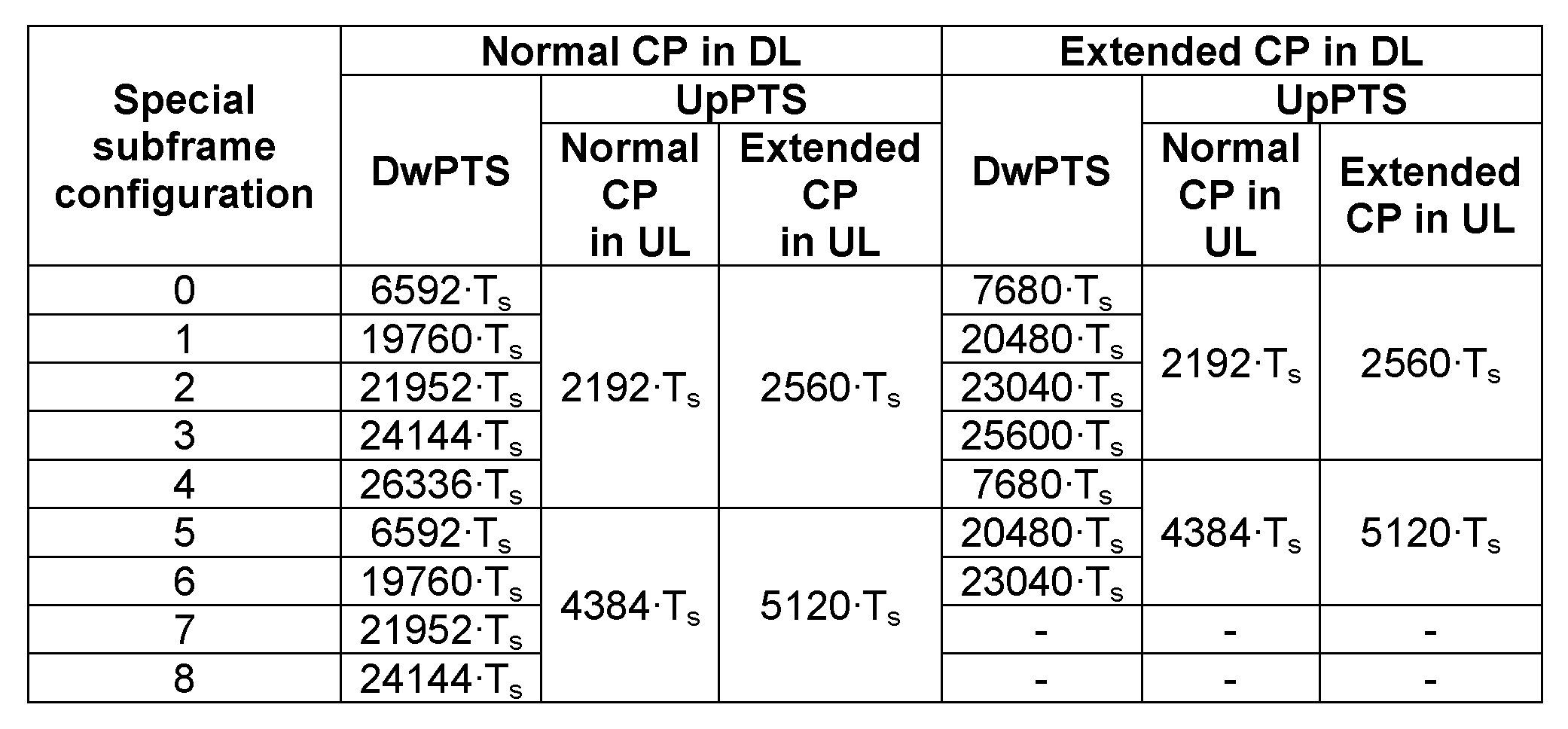
특수 서브프레임은 노멀 CP일 때 9가지 조합이, 확장 CP일 때 7가지 조합이 가능하다.
TDD 통신 시스템에서는 상술한 것처럼, 시간에 따라 특정 서브프레임을 하향링크 서브프레임 또는 상향링크 서브프레임으로 변환하는 것이 가능하다. 상향링크 서브프레임에서 하향링크 서브프레임으로 변환하는 경우에는 서브프레임 변환을 위한 보호 구간(guard period)이 필요 없다. 그러나, 하향링크 서브프레임에서 상향링크 서브프레임으로 전환하는 경우에는 보호 구간이 필요하다. 그 이유는 상향링크 전송 시 각 단말이 상향링크 동기를 일치시키기 위해 TA(Timing Advance)를 수행하기 때문이다. 그러므로 보호 구간이 없다면 단말이 하향링크로 신호를 수신하는 구간과 상향링크로 신호를 수신하는 구간이 겹칠 수 있기 때문이다.
보호 구간에서는 신호를 전송하거나 수신할 수 없으므로 하향링크 서브프레임에 이어서 상향링크 서브프레임이 배치되는 경우가 빈번할수록 보호구간의 오버헤드가 증가하게 된다. 그러므로, 보호 구간의 오버헤드를 줄이기 위해서 하향링크 서브프레임을 연속적으로 배치한 뒤 상향링크 서브프레임을 연속적으로 배치하는 기법을 적용하는 것이 필요하다. 일례로 LTE 시스템에서는 10개의 서브프레임에서 하나 또는 두 개의 보호 구간을 배치하고 보호 구간 사이에서는 하향링크 서브프레임 또는 상향링크 서브프레임을 연속적으로 배치한다. 기지국이 스케줄링을 관장하는 셀룰러 통신 시스템에서는 상향링크 서브프레임이 연속적으로 배치된 경우에 상향링크 서브프레임의 스케줄링을 앞선 하향링크 서브프레임에서 수행하게 된다.
도 8 및 도 9는 3GPP 무선접속망 규격을 기반으로 한 단말과 UTRAN (UMTS Terrestrial Radio Access Network) 사이의 무선인터페이스 프로토콜 (Radio Interface Protocol)의 구조를 나타낸다. 도 8의 무선인터페이스 프로토콜은 수평적으로 물리계층(Physical Layer), 데이터링크계층(Data Link Layer) 및 네트워크계층(Network Layer)으로 이루어지며, 수직적으로는 데이터정보 전송을 위한 사용자평면(User Plane)과 제어신호(Signaling)전달을 위한 제어평면(Control Plane)으로 구분된다. 도 8의 프로토콜 계층들은 통신시스템에서 널리 알려진 개방형시스템간 상호접속 (Open System Interconnection; OSI)기준모델의 하위 3개 계층을 바탕으로 L1 (제1계층), L2 (제2계층), L3(제3계층)로 구분될 수 있다.
이하에서 상기 도 8의 무선프로토콜 제어평면과 도 9의 무선프로토콜 사용자평면의 각 계층을 설명한다.
제1계층인 물리계층은 물리채널(Physical Channel)을 이용하여 상위 계층에게 정보전송서비스(Information Transfer Service)를 제공한다. 물리계층은 상위에 있는 매체접속제어(Medium Access Control)계층과는 전송채널(Transport Channel)을 통해 연결되어 있으며, 이 전송채널을 통해 매체접속제어계층과 물리계층 사이의 데이터가 이동한다. 그리고, 서로 다른 물리계층 사이, 즉 송신측과 수신측의 물리계층 사이는 물리채널을 통해 데이터가 이동한다.
제2계층의 매체접속제어 (Medium Access Control; 이하 MAC로 약칭)는 논리채널(Logical Channel)을 통해 상위 계층인 무선링크제어(Radio Link Control)계층에게 서비스를 제공한다. 제2계층의 무선링크제어(Radio Link Control; 이하 RLC로 약칭)계층은 신뢰성 있는 데이터의 전송을 지원한다. RLC 계층의 기능이 MAC내부의 기능 블록으로 구현될 수도 있다. 이러한 경우에는 RLC계층은 존재하지 않을 수도 있다. 제2계층의 PDCP 계층은 IPv4나 IPv6와 같은 IP 패킷 전송시에 대역폭이 작은 무선 구간에서 효율적으로 전송하기 위하여 상대적으로 크기가 크고 불필요한 제어정보를 담고 있는 IP 패킷 헤더 사이즈를 줄여주는 헤더압축 (Header Compression) 기능을 수행한다.
제3계층의 가장 하부에 위치한 무선자원제어(Radio Resource Control; 이하 RRC라 약칭함)계층은 제어평면에서만 정의되며, 무선베어러 (Radio Bearer; RB라 약칭함)들의 설정(Configuration), 재설정(Re-configuration) 및 해제(Release)와 관련되어 논리채널, 전송채널 및 물리채널들의 제어를 담당한다. 이때, RB는 단말과 UTRAN 간의 데이터 전달을 위해 제2계층에 의해 제공되는 서비스를 의미한다.
망에서 단말로 데이터를 전송하는 하향전송채널로는 시스템정보를 전송하는 BCH(Broadcast Channel)과 그 이외에 사용자 트래픽이나 제어메시지를 전송하는 하향 SCH(Shared Channel)이 있다. 하향 멀티캐스트 또는 방송 서비스의 트래픽 또는 제어메시지의 경우 하향 SCH를 통해 전송될 수도 있고, 또는 별도의 하향 MCH(Multicast Channel)을 통해 전송될 수도 있다. 한편, 단말에서 망으로 데이터를 전송하는 상향전송채널로는 초기 제어메시지를 전송하는 RACH(Random Access Channel)와 그 이외에 사용자 트래픽이나 제어메시지를 전송하는 상향 SCH(Shared Channel)가 있다.
그리고, 하향전송채널로 전달되는 정보를 망과 단말 사이의 무선구간으로 전송하는 하향물리채널로는, BCH의 정보를 전송하는 PBCH(Physical Broadcast Channel), MCH의 정보를 전송하는 PMCH(Physical Multicast Channel), PCH와 하향 SCH의 정보를 전송하는 PDSCH(Physical Downlink shared Channel), 그리고 하향 또는 상향 무선자원 할당정보(DL/UL Scheduling Grant)등과 같이 제1계층과 제2계층에서 제공하는 제어 정보를 전송하는 PDCCH(Physical Downlink Control Channel, 또는 DL L1/L2 control channel 이라고도 함)가 있다. 한편, 상향 전송채널로 전달되는 정보를 망과 단말 사이의 무선구간으로 전송하는 상향 물리채널로는 상향 SCH의 정보를 전송하는 PUSCH(Physical Uplink Shared Channel), RACH 정보를 전송하는 PRACH(Physical Random Access Channel), 그리고 HARQ ACK 또는 NACK, 스케줄링 요청(SR; Scheduling Request), CQI(Channel Quality Indicator) 보고등과 같이 제1계층과 제2계층에서 제공하는 제어 정보를 전송하는 PUCCH(Physical Uplink Control Channel)이 있다.
일반적으로, 단말이 상향링크 무선자원이 필요한 경우, 단말은 기지국에게 무선자원을 요청을 해야 무선자원을 할당 받을 수 있다. 만약 상기 단말이 상기 기지국으로부터 미리 설정된 스케줄링 요청(Scheduling Request; SR)을 위한 PUCCH(Physical Uplink Control Channel) 무선자원을 가지고 있다면, 단말은 상기 PUCCH를 통해 상기 기지국으로 무선자원을 요청할 수 있고, 상기 기지국은 이에 따라 적절한 무선자원을 상기 단말에게 할당하고, 상기 단말은 상기 무선자원을 이용하여 데이터를 상기 기지국으로 전송하게 된다.
이하에서는 고신뢰 저지연 서비스를 제공하기 위한 단말의 스케줄링 요청(scheduling request; SR)에 대해 설명한다.
고신뢰 저지연 서비스에서는 데이터 패킷을 sTTI(short TTI)에서 전송하기 때문에 대용량의 대역폭이 필요하다. 그러므로, 다수의 단말이 동일 TTI에서 스케줄링 요청을 하는 경우에 기지국이 모든 단말에게 스케줄링을 수행할 수 없다. 예를 들어, 차량 통신에서 사고가 발생하면 사고를 감지한 주변의 자동차들은 동시에 기지국에 스케줄링 요청을 하는 경우 기지국은 동시에 모든 자동차에게 스케줄링을 수행할 수 없다.
상술한 이유 때문에 기지국은 스케줄링 요청 단계에서부터 정보의 중요도를 구분하여 중요한 정보부터 우선적으로 스케줄링을 수행하는 것이 필요하다. 정보의 중요도를 결정하는 가장 대표적인 방법은 QoS(Quality of Service) 조건을 활용하는 것이다. 일례로, 기지국이 각 단말이 현재 제공받는 서비스의 QoS 조건을 알고 있다면, 다수의 단말로부터 스케줄링 요청을 수신할 때 QoS에 따라 스케줄링의 우선순위를 결정할 수 있다. 현재 LTE 시스템에서는 각 단말이 여러 개의 QoS가 맵핑된 LCGID(Logical Channel Group Identifier)를 BSR(Buffer Status Report) 단계에서 전송함으로써 스케줄링의 우선순위를 기지국에 알린다. 그러나 해당 기법은 BSR 단계를 수행해야 하므로 지연이 증가하는 단점이 있어, 차세대 무선통신의 저지연 요구 조건을 만족시키기 어렵다. 이러한 문제를 해결하기 위해 QoS에 따라 서로 다른 스케줄링 요청 자원을 각 단말에게 할당하는 기법(Mediatek Inc, Smart congestion control for RRC connected mode in LTE advanced systems, WO 2015131854 A1)이 제안된다.
단말에게 다수의 스케줄링 요청 자원을 할당해서 스케줄링 요청이 있을 때 QoS를 구분하는 기법은 단말에게 할당하는 스케줄링 요청 자원을 증가시키는 단점이 존재한다. 저지연 서비스에서는 각 단말에게 스케줄링 요청 자원을 짧은 주기로 할당해야 하므로 스케줄링 요청 자원의 증가에 따른 시스템 오버헤드의 증가가 더 부각될 수 있다. 이로써, 셀 내 단말의 수가 많은 경우에 기지국은 각 단말에게 원하는 만큼의 스케줄링 요청 자원을 할당할 수 없게 된다. 일례로, 차량 통신에서는 왕복 10차선의 3개 고속도로의 교차로에서 반경 1.6km에 15840대의 차량이 존재할 수 있으므로(Qualcomm, 3GPP S1-152275) 해당 기법을 적용하기 어렵다.
또한, QoS에 따라서만 정보의 중요도를 구분하는 기법에서는 중복된 정보를 걸러내지 못하는 단점이 있다. 일례로, 차량 사고가 감지되었을 때 사고를 감지한 주변의 차량들은 모두 기지국으로 스케줄링을 요청할 수 있는데, 차량들은 모두 높은 QoS를 갖는 사고 알림용 스케줄링 요청을 수행하게 된다. 그러나, 해당 정보는 중복된 정보이므로, 기지국은 모든 차량에게 자원을 스케줄링할 필요가 없다. 만약, 서로 다른 경로에서 중요도가 높은 QoS를 갖는 스케줄링 요청이 동시에 수신되었다면 기지국은 동일한 경로의 중복된 정보를 걸러내서 동일한 경로의 중복된 정보를 걸러내서 다른 경로의 차량들에게 스케줄링을 수행하는 것이 필요하다. 즉, 정보의 중요도가 비슷하다면 중복되지 않은 정보들을 우선적으로 스케줄링하는 것이 필요하며, 기지국은 스케줄링 요청을 하는 단말의 위치를 기반으로 정보의 중복 여부를 추정할 수 있다.
단말의 위치를 기반으로 정보의 중복여부를 추정하는 방법으로는 각 단말의 위치를 고려해서 스케줄링 요청 자원을 할당하는 방법과 각 지역별로 클러스터를 만들고 클러스터 헤드를 설정하는 방법이 있다.
단말의 위치를 반영해 스케줄링 요청 자원을 할당하는 방법에서는 위치를 구분하기 위해 추가적인 스케줄링 요청 자원을 할당해야 한다는 단점이 있다. 만약 QoS와 단말의 위치를 모두 표현할 수 있도록 스케줄링 요청 자원을 할당한다면 스케줄링 요청 자원의 오버헤드가 더욱 증가하는 문제가 있다.
각 지역 별로 클러스터를 만드는 방법은 2가지로 나눌 수 있다. 한 가지 방법은 클러스터 내 각 단말이 센싱을 하고 센싱 정보를 클러스터 헤드로 전달하면 클러스터 헤드가 기지국에 신호를 전달하는 방법이다. 이 방법은 지연이 증가하는 단점과 클러스터 헤드의 오버헤드가 커지는 단점이 있다. 다른 한 가지 방법은 클러스터 내 클러스터 헤드만 센싱을 하고 해당 정보를 기지국에 전송하는 방법이다. 해당 방법은 신호 전달의 지연은 감소하나 센싱을 하지 못하는 사각지대가 발생한다는 단점을 가지고 있다. 상기 2가지 방법 모두 각 단말이 이동하는 경우에는 주기적으로 클러스터를 업데이트하고 클러스터 헤드를 매번 지정해야하므로 이동 단말의 경우에는 시그널링 오버헤드가 증가하는 단점이 있다.
본 명세서에서는 스케줄링 요청 자원의 증가를 최소화하면서 각 단말의 위치를 고려해 스케줄링 요청 자원을 할당하는 방법을 제안한다. 즉, 본 명세서는 단말의 위치 정보를 반영해서 스케줄링 요청 자원을 할당하는 방법을 제안한다. 그러므로 본 명세서는 단말들이 주위를 센싱하고 센싱한 정보를 기지국에 전달하는 서비스에 모두 적용될 수 있다.
또한, 본 명세서는 단말의 위치 정보를 반영해서 스케줄링 요청 자원을 할당하기 위해 스케줄링 요청 자원을 서로 다른 자원 할당 주기를 갖는 제1 스케줄링 요청 자원과 제2 스케줄링 요청 자원으로 나누고 이때 단말의 동작을 제안한다. 여기서, 제1 스케줄링 요청 자원은 스케줄링 요청 자원을 포함하는 자원에 대응하고 제1 자원이라고도 부를 수 있다. 제2 스케줄링 요청 자원은 스케줄링 요청 자원을 포함하는 자원에 대응하고 제2 자원이라고도 부를 수 있다.
1. 위치 정보를 반영한 스케줄링 요청 자원을 할당하는 알고리즘
본 명세서에서 논의하는 스케줄링 요청 자원은 논리 자원이다. 논리 스케줄링 요청 자원은 물리적으로 서로 다른 자원 블록, 자원 요소, 서로 다른 스프레딩 신호, 서로 다른 시퀀스, 서로 다른 프리앰블, 서로 다른 물리 안테나 및 서로 다른 논리 안테나 등에 맵핑될 수 있다.
기지국은 단말이 기지국에 전송한 PMI(Precoding Matrix Indicator) 정보 또는 상향링크 참조신호(예를 들어, LTE 시스템의 SRS(Sounding Reference Signal) 또는 UL DM-RS(Uplink Demodulation-Reference Signal))를 이용해 위치를 추정할 수 있다. 기지국 PMI 등을 이용해서 단말의 위치를 구분하면 모뎀 외부의 센서의 도움없이 빠르게 단말의 위치를 파악할 수 있는 장점이 있다. 본 명세서의 기법은 특정 다중 안테나 용 프리코딩 매트릭스(precoding matrix)로 제한되지 않으며, 본 명세서에서 사용하는 PMI는 기지국 빔포밍(beamforming)을 위해 단말이 기지국에 궤환하는 정보를 모두 포함한다. 예를 들어, 아날로그 빔포밍(RF 빔포밍)이 적용되는 시스템에서 본 명세서의 PMI는 선호하는 아날로그(RF) 빔 인덱스 또는 선호하는 프리앰블(또는 참조신호)의 인덱스에 해당할 수 있다. 또는, 참조신호를 빔포밍된 형태로 전송하는 시스템에서도 유사하게 PMI는 빔 인덱스 또는 이에 상응하는 안테나 포트 인덱스에 해당할 수 있다.
알고리즘의 목적은 스케줄링 요청의 성공 확률은 일정하게 유지하면서 스케줄링 요청을 위한 자원은 적게 할당하는 것이다. 이를 달성하기 위해 단말의 위치를 반영하여 스케줄링 요청 자원을 할당하는 것을 특징으로 한다. 단말의 위치를 스케줄링 요청 자원에 반영하면 얻는 장점은 다음과 같다. 스케줄링 요청 자원은 단말의 수가 늘어날수록 부족하게 되지만, 단말의 수가 늘어나면 특정 이벤트가 발생한 경우에 이를 센싱하는 단말의 수도 늘어나게 된다. 그러므로 단일 이벤트를 센싱하는 단말의 수가 늘어나는 경우에는 각 단말이 스케줄링 요청을 성공적으로 전송하는 확률이 감소하더라도, 단일 이벤트 전송을 위한 스케줄링 요청이 성공적으로 기지국에 전송될 확률은 일정하게 유지될 수 있다. 자동차 사고, 화재, 홍수 등을 센싱해서 해당 정보를 상향링크로 기지국에 전송하는 서비스에서는 이벤트가 지역별로 발생하므로, 각 지역에서 스케줄링 요청을 성공적으로 기지국에 전송할 확률을 일정하게 유지함으로써 각 이벤트에 대한 스케줄링 요청이 기지국에 성공적으로 전송될 확률을 일정하게 유지할 수 있다.
단말의 수가 증가하더라도 지역별로 스케줄링 요청의 성공 확률을 일정하게 유지하는 알고리즘의 주요 특징은 다음과 같다.
(1) 임의의 서비스를 위해 사용할 수 있는 스케줄링 요청 자원이 N개인 경우에 스케줄링 요청 자원의 할당을 위해 사용되는 셀 내 지역의 수는 N개보다 작아야 한다.
- 셀 내 지역의 수가 N개보다 많으면 이를 스케줄링 요청 자원을 통해 구분할 수 없으므로 기지국은 셀 내 지역의 수를 N개보다 작거나 같게 유지해야 한다.
- 일례로, 기지국이 PMI가 다르면 서로 다른 지역으로 구분하고 단말이 기지국에 전송하는 PMI의 종류가 M개이고 M이 N보다 큰 경우를 가정하자. 이 경우 양자화(quantization)을 통해 M개의 PMI를 N개의 지역에 맵핑시켜야 한다.
(2) 특정 지역에 위치한(PMI를 갖는) 단말들 중 하나 이상은 다른 단말들과 중복되지 않는 전용 스케줄링 요청 자원을 할당한다. 이는 지역별로 독립적인 스케줄링 요청 자원을 하나 이상 확보하기 위해서이다.
- 일례로, 스케줄링 요청 자원이 3개이고 단말 1과 2의 PMI가 동일하며, 단말 3과 4의 PMI가 동일한 경우에는 단말 1과 단말 3은 각각 스케줄링 요청 자원을 할당받고, 단말 2와 단말 4는 동일한 스케줄링 요청 자원을 할당받는다.
- 일례로, 스케줄링 요청 자원이 3개이고, 단말 1 내지 단말 3의 PMI가 동일하며 단말 4와 5의 PMI가 동일한 경우에는 단말 1과 다날 4가 각각 스케줄링 요청 자원을 할당받고, 단말 2,3,5가 동일한 스케줄링 요청 자원을 할당받는다.
(3) (1)번 조건이 충족되면 동일 지역(PMI가 동일한)의 단말들은 다른 지역(PMI가 다른)의 단말들보다 우선적으로 서로 다른 스케줄링 요청 자원에 할당한다. 다시 말해서, 스케줄링 요청 자원이 중복되는 경우에는 서로 다른 지역(PMI가 다른)의 단말을 동일한 스케줄링 요청 자원에 할당한다. 이는 특정 지역 사고 발생 시 해당 지역의 단말들이 동시에 스케줄링을 요청할 확률이 다른 지역에 있는 단말이 동시에 스케줄링을 요청할 확률보다 크기 때문이다. 또한, 전용 스케줄링 요청 자원을 할당받지 못한 단말들은 전용 스케줄링 요청 자원을 할당받은 단말이 센싱하지 못하는 영역에서 사고가 발생하더라도 기지국이 이를 임의의 확률 이상으로 알 수 있도록 하는 효과가 있다.
- 일례로, 스케줄링 요청 자원이 2개이고 단말 1의 PMI와 단말 2의 PMI가 동일하다면 단말 1과 단말 2는 서로 다른 스케줄링 요청 자원에 할당되어야 한다.
- 일례로, 스케줄링 요청 자원이 2개이고 단말 1과 단말 2의 PMI는 동일하지만 단말 3은 다른 PMI를 가지고 있다면, 단말 1과 단말 3은 서로 다른 스케줄링 요청 자원에 할당되고 단말 2에게는 스케줄링 요청 자원을 할당하지 않는다.
(4) (3)번의 방식과 달리 동일 지역(PMI가 동일한)의 단말들은 우선적으로 동일한 스케줄링 요청 자원을 할당 받는다. 이는 특정 지역에서 사건이 발생한 경우에 동일 지역의 단말들이 보내고자 하는 정보가 동일할 확률이 높기 때문에 특정 지역의 단말 중 임의의 단말을 스케줄링 해줘도 기지국은 동일한 정보를 수신할 수 있기 때문이다.
- 일례로, 스케줄링 요청 자원이 2개이고 단말 1과 단말 2의 PMI는 동일하지만 단말 3은 다른 PMI를 가지고 있다면, 단말 1과 단말 2는 동일한 스케줄링 요청 자원에 할당되고 단말 3은 다른 스케줄링 요청 자원을 할당받는다.
- 일례로, 스케줄링 요청 자원이 4개이고 단말 1 내지 단말 3의 PMI는 동일하고 단말 4 내지 단말 6의 PMI가 동일한 경우에, 단말 1과 단말 4는 전용 스케줄링 요청 자원을 할당받고 단말 2와 3은 공통 스케줄링 요청 자원을 할당받고 단말 5와 6은 공통 스케줄링 요청 자원을 할당받는다.
(5) (1)번 조건에서 스케줄링 요청 자원을 할당받지 못하는 단말을 제거하기 위해서 스케줄링 요청 자원의 수가 N개이면 셀 내 지역의 수를 N-1개 이하가 되도록 한다.
- 일례로, 스케줄링 요청 자원이 3개이고 총 PMI의 개수가 2개이며 단말 1 내지 단말 3의 PMI가 동일하고 단말 4 내지 단말 10의 PMI가 동일한 경우에는 단말 1과 단말 4를 서로 다른 스케줄링 요청 자원에 할당하고 단말 2,3,5 내지 10을 동일한 스케줄링 요청 자원에 할당한다.
- 단말들이 공통으로 할당받은 스케줄링 요청 자원은 LTE 시스템의 랜덤 액세스 채널과 같이 프리앰블을 전송하는 자원일 수 있다.
(6) (2)번 조건을 강화해서 동일 지역(PMI가 동일한)의 단말들은 동일한 스케줄링 요청 자원을 할당받지 못하게 한다. 이는 스케줄링 요청 자원의 수에 따라 스케줄링 요청이 가능한 최대 단말의 수를 제한하는 효과를 갖는다. (4)번 조건을 동시에 적용하면 스케줄링 요청의 충돌 확률을 감소시키는 효과가 있다.
- 일례로, 스케줄링 요청 자원이 3개이고 총 PMI의 개수가 2개이며 단말 1 내지 단말 3의 PMI가 동일하고 단말 4 내지 10의 PMI가 동일한 경우에는 단말 1과 단말 4를 서로 다른 스케줄링 요청 자원에 할당하고 단말 2와 단말 5를 동일한 스케줄링 요청 자원에 할당한다. 단말 3, 단말 6 내지 10에는 스케줄링 요청 자원을 할당하지 않는다.
(7) 기지국이 공통 스케줄링 요청 자원(예를 들어, 동일 프리앰블)으로부터 스케줄링 요청을 받은 경우 기지국이 공통 스케줄링 요청 자원을 할당받은 단말 중 임의의 단말에게 상향링크 자원을 할당하기 위해서는 동일 스케줄링 요청 자원을 할당받은 단말들은 서로 다른 물리계층 단말 식별자(예를 들어, C-RNTI(Cell-Radio Network Temporary Identifier))를 할당받아야 한다.
- 일례로, 단말 1 내지 3이 동일한 스케줄링 요청 자원을 할당받았고 단말 1과 단말 2가 동시에 스케줄링 요청을 수행한 경우를 가정한다. 기지국은 단말 1 내지 3 중 어떤 단말이 스케줄링을 요청했는지 알 수 없기 때문에 3개의 단말에게 모두 상향링크 스케줄링을 수행(상향링크 그랜트를 전송)하거나 임의의 단말에게만 상향링크 스케줄링을 수행할 수 있다. 단말 1 내지 3은 기지국이 전송한 상향링크 스케줄링 신호가 자신의 것인지를 확인하기 위해서 서로 다른 물리계층 단말 식별자를 보유해야 한다.
2. 알고리즘을 구현을 위한 스케줄링 요청 자원을 할당하는 방법과 단말의 동작
상술한 알고리즘을 적용하면 공통 스케줄링 요청 자원을 할당받은 단말들은 스케줄링 요청을 전송한 경우에 자원을 할당받지 못할 확률이 기존보다 높아진다. 또한, 단말이 비지역 기반 서비스와 지역 기반 서비스를 동시에 받고자 하는 경우에는 공통 스케줄링 요청 자원을 두 서비스 모두에 적용하는 것이 적합하지 않다. 이러한 문제를 해결하기 위해 스케줄링 요청 자원을 제1 스케줄링 요청 자원과 제2 스케줄링 요청 자원으로 나누고 제1 스케줄링 요청 자원에서 공통 스케줄링 요청 자원을 할당받은 단말이 제2 스케줄링 요청 자원에서 추가적인 스케줄링 요청 자원을 할당받을 수 있는 기법을 제안한다. 일반적으로, 제1 스케줄링 요청 자원에는 전용 스케줄링 요청 자원과 공통 스케줄링 요청 자원을 할당하고, 제2 스케줄링 요청 자원에는 전용 스케줄링 요청 자원만 할당한다. 또한, 제1 스케줄링 요청 자원에는 위치 기반으로 스케줄링 요청 자원을 할당하고 제2 스케줄링 요청 자원에는 위치에 관계없이 스케줄링 요청 자원을 할당하는 방법을 적용할 수 있다.
도 10은 본 명세서의 실시예에 따른 제1 스케줄링 요청 자원 및 제2 스케줄링 요청 자원이 할당되는 일례를 나타낸다.
도 10에 의하면, 제1 스케줄링 요청 자원에서 단말 1은 전용 스케줄링 요청 자원(1010)을 할당받고, 단말 2 내지 4는 공통 스케줄링 요청 자원(1020)을 할당받는다. 단말 2 내지 4는 제2 스케줄링 요청 자원에서 전용 스케줄링 요청 자원(1030)을 할당받았고, 제2 스케줄링 요청 자원의 주기는 제1 스케줄링 요청 자원의 주기보다 3배가 길게 설정되었다.
단말이 할당받은 제1 스케줄링 요청 자원이 해당 단말에게만 할당된 전용 스케줄링 요청 자원(dedicated scheduling request resource)인 경우에는 단말에게 추가적인 스케줄링 요청 자원을 할당할 필요가 없다. 그러나, 단말이 할당받은 제1 스케줄링 요청 자원이 공통으로 할당받는 공통 스케줄링 요청 자원(common scheduling request resource(예를 들어, 랜덤 액세스 채널))이어서 충돌이 발생할 수 있는 경우에는 각 단말이 전용으로 할당받는 스케줄링 요청 자원이 필요하다.
2.1. 단말의 동작 방법
제1 스케줄링 요청 자원 또는 제2 스케줄링 요청 자원에서 스케줄링 요청 자원을 할당받은 단말은 기존 LTE에서와 동일한 동작 방법을 적용할 수 있다. 제1 스케줄링 요청 자원에서는 공통 스케줄링 요청 자원을 할당받고, 제2 스케줄링 요청 자원에서는 전용 스케줄링 요청 자원을 할당받은 단말들은 다음과 같은 방식으로 동작한다. 트래픽 발생 시 단말은 스케줄링 요청을 전송할 자원을 제1 스케줄링 요청 자원과 제2 스케줄링 요청 자원 중에서 선택한다. 즉, 제1 스케줄링 요청 자원과 제2 스케줄링 요청 자원 둘 다 할당받거나 제1 스케줄링 요청 자원과 제2 스케줄링 요청 자원 둘 다에 대한 할당 정보를 수신하되, 실제로 스케줄링 요청은 제1 스케줄링 요청 자원과 제2 스케줄링 요청 자원 중 선택된 하나의 자원에서 전송된다. 선택하는 방법은 총 3가지로 나눌 수 있다.
방법 1: 최단 시간 스케줄링 요청 방법
- 제1 스케줄링 요청 자원과 제2 스케줄링 요청 자원 중에서 트래픽이 발생한 시점에서 가장 가까운 자원을 사용하여 스케줄링 요청 자원을 수행한다.
- 제1 스케줄링 요청 자원과 제2 스케줄링 요청 자원이 동일한 서브프레임에 위치하면 제2 스케줄링 요청 자원을 사용하여 스케줄링 요청 자원을 수행한다.
방법 2: 신뢰도 중심 스케줄링 요청 방법
- 서비스가 요구하는 최대 스케줄링 요청 지연 시간 내에 제2 스케줄링 요청 자원이 존재하면 제2 스케줄링 요청 자원을 사용하여 스케줄링 요청을 수행한다.
- 서비스가 요구하는 최대 스케줄링 요청 지연 시간 내에 제2 스케줄링 요청 자원이 존재하지 않으면 제1 스케줄링 요청 자원을 사용하여 스케줄링 요청을 수행한다.
방법 3: 서비스 지정 스케줄링 요청 방법
- 제1 스케줄링 요청 자원을 사용해 스케줄링 요청을 수행하는 서비스와 제2 스케줄링 요청 자원을 사용해 스케줄링 요청을 수행하는 서비스의 종류를 기지국이 단말에게 알려준다. 단말은 수신한 정보를 바탕으로 서비스에 따라 제1 스케줄링 요청 자원과 제2 스케줄링 요청 자원 중 스케줄링 요청 자원으로 활용할 자원을 지정한다.
- 기지국이 제1 스케줄링 요청 자원을 사용한 스케줄링 요청을 수신하지 못했다고 단말이 판단하면, 충돌 해제(contention resolution)를 위해 이후에는 제2 스케줄링 요청 자원을 사용하여 스케줄링 요청을 전송한다.
2.2. 제1 스케줄링 요청 자원 및 제2 스케줄링 요청 자원을 할당하기 위한 시그널링
기지국이 단말에게 제1 스케줄링 요청 자원과 제2 스케줄링 요청 자원을 할당하기 위해 전송한 시그널링을 단말이 수신하는 순서는 1)기지국이 브로드캐스트하는 제1 스케줄링 요청 자원에 대한 정보 및 제2 스케줄링 요청 자원에 대한 정보를 수신 2)기지국이 단말 별로 전송하는 제1 스케줄링 요청 자원에 대한 정보 및 제2 스케줄링 요청 자원에 대한 정보를 수신과 같다.
1)에서 단말은 기지국이 셀 내 브로드캐스트하는 정보를 수신해서 제1 스케줄링 요청 자원 및 제2 스케줄링 요청 자원의 존재 여부와 제1 스케줄링 요청 자원 및 제2 스케줄링 요청 자원의 주기 정보를 수신한다.
2)에서 각 단말은 자신이 할당받은 스케줄링 요청 자원에 관한 정보를 기지국으로부터 수신한다. 각 단말은 제1 스케줄링 요청 자원 및 제2 스케줄링 요청 자원에서 각각 스케줄링 요청 자원을 할당받을 수 있다. 또한, 서비스 별로 어떤 스케줄링 요청 자원을 사용하는지를 기지국으로부터 수신한다.
위와 같이 제1 스케줄링 요청 자원에 대한 정보 및 제2 스케줄링 요청 자원에 대한 정보를 기지국이 브로드캐스트하면 기지국이 각 단말에게 전송하는 스케줄링 요청 자원의 할당을 위한 시그널링의 오버헤드를 감소시키는 효과가 있다.
2.2.1. 기지국이
브로드캐스트하는
제1 스케줄링 요청 자원에 대한 정보 및 제2 스케줄링 요청 자원에 대한 정보
기지국이 제1 스케줄링 요청 자원 및 제2 스케줄링 요청 자원에 대한 정보를 브로드캐스트하는 경우 이에 포함될 수 있는 정보는 다음과 같다.
| 제 1 스케줄링 요청 자원에 대한 정보 | 시간 자원 정보 | 심볼(서브프레임) 시작점과 심볼(서브프레임) 개수 정보 또는 심볼(서브프레임) 시작점과 끝점 |
| 주파수 자원 정보 | 부 반송파 시작점과 부 반송파 개수 또는 부 반송파의 시작점과 끝점 | |
| 자원 할당 주기 | 자원 할당 주기를 서브프레임 개수 또는 TTI 개수 또는 심볼 개수 등으로 표현 | |
| 공통 스케줄링 요청 자원의 할당 가능 여부 | 해당 지시자가 0 이면 제 1 자원에서 전용 스케줄링 요청 자원의 할당만 가능함을 나타냄. 1 이면 공통 스케줄링 요청 자원의 할당이 가능함을 의미 | |
| 채널 특성 피드백 전송 주기 | - 기지국이 단말의 위치를 추적할 수 있도록 위치 기반의 전용 스케줄링 요청 자원을 할당받은 단말이 기지국에 채널 특성(e.g. PMI)을 피드백하는 주기- 상향링크 참조신호 전송 주기를 설정한 경우 해당 주기를 설정하지 않을 수 있다. | |
| 상향링크 참조신호 전송 주기 | - 기지국이 단말의 위치를 추적할 수 있도록 위치 기반의 전용 스케줄링 요청 자원을 할당 받은 단말이 기지국에 상향링크 참조신호(e.g. SRS)를 전송하는 주기- 채널 특성 피드백 전송 주기를 설정한 경우 해당 주기를 설정하지 않을 수 있다. | |
| 제 2 스케줄링 요청 자원에 대한 정보 | 시간 자원 정보 | 심볼(서브프레임) 시작점과 심볼(서브프레임) 개수 정보 또는 심볼(서브프레임) 시작점과 끝점 |
| 주파수 자원 정보 | 부 반송파 시작점과 부 반송파 개수 또는 부 반송파의 시작점과 끝점 | |
| 자원 할당 주기 | 자원 할당 주기를 서브 프레임 개수 또는 TTI 개수 또는 심볼 개수 등으로 표현 |
2.2.2. 기지국이 단말 별로 전송하는 제1 스케줄링 요청 자원에 대한 정보 및 제2 스케줄링 요청 자원에 대한 정보
제1 스케줄링 요청 자원은 제2 스케줄링 요청 자원보다 짧은 주기로 스케줄링 요청 자원을 할당하므로 스케줄링 요청 자원의 할당을 위해 기지국이 단말에게 보다 자주 신호를 전송해야한다. 그러므로 기지국이 임의의 단말에게 제2 자원 내 스케줄링 요청 자원의 할당 정보를 전송할 때 제1 자원에 관한 정보를 일부 포함시킴으로써, 제1 자원 내 스케줄링 요청 자원을 할당할 때 시그널 오버헤드를 감소시킬 수 있다. 또한, 단말이 서비스 종류에 따라 어떤 스케줄링 요청 자원을 사용할지를 지시하는 정보를 전송한다. 여기서, 제1 자원 내 스케줄링 요청 자원은 제1 스케줄링 요청 자원에 대응하고, 제2 자원 내 스케줄링 요청 자원은 제2 스케줄링 요청 자원에 대응할 수 있다.
제2 자원 내 스케줄링 요청 자원의 할당을 위한 시그널에 포함된 정보는 다음과 같다.
| 제 1 자원 내 스케줄링 요청 자원의 할당 지시자 | 제 1 자원 내 스케줄링 요청 자원이 할당되었음을 나타내는 지시자 |
| 스케줄링 요청 수행 방법 지시자 | 2.1의 스케줄링 요청 선택 방법 중 어떤 방법으로 스케줄링 요청 자원을 선택할지를 기지국이 단말이게 지시하는 정보 |
| 제 1 자원 내 스케줄링 요청 자원의 할당 주기 | 스케줄링 요청 자원이 할당되는 주기를 나타내는 정보를 포함함 |
| 제 2 자원 내 스케줄링 요청 자원의 할당 지시자 | 제 2 자원 내 스케줄링 요청 자원이 할당되었음을 나타내는 지시자 |
| 제 2 자원 내 스케줄링 요청 자원의 할당 정보 | 스케줄링 요청 자원이 할당된 시간, 주파수와 자원 할당 주기를 나타내는 정보를 포함함 |
| 데이터 발생 시 사용할스케줄링 요청 자원의 선택을 위한 정보 | - 실시예 1: 데이터 발생 시 제 1 자원으로 스케줄링 요청을 전송하는 서비스에 대한 정보를 송신함. 서비스 정보는 데이터 라디오 베어러 ID 또는 QoS ID등으로 표현됨. 일례로, 지역 정보를 센싱 후 기지국에 전송하는 서비스들은 제 1 자원으로 스케줄링 요청을 수행하도록 지시할 수 있음.- 실시예 2: 데이터 라디오 베어러 또는 MAC계층의 서비스 종류 지시자 (e.g. LTE의 LCID)의 요구 지연 시간 및 요구 신뢰도 정보를 전송함. 단말은 해당 정보와 제 1 자원과 제 2 자원의 할당 주기를 고려하여 어떤 자원에서 스케줄링 요청 자원을 수행할지 지정함 |
제1 자원 내 스케줄링 요청 자원의 할당을 위한 시그널에 포함된 정보는 다음과 같다.
| 제 1 자원 내 스케줄링 요청 자원의 할당 정보 | 스케줄링 요청 자원이 할당된 시간, 주파수를 나타내는 정보를 포함함 |
제1 자원 내 스케줄링 요청 자원을 할당하기 위한 시그널은 L1, L2 또는 L3 시그널로 전송될 수 있다.
2.2.3. 제1 스케줄링 요청 자원이
PMI
기반으로 각
단말에게
할당되는 경우 기지국이 브로드캐스트하는 정보
기지국이 PMI를 사용해 단말의 위치를 추정하는 경우에 L1, L2 또는 L3의 시그널링 오버헤드를 줄이기 위해 다음과 같은 기법이 적용될 수 있다.
- 기지국은 PMI 변화에 따른 스케줄링 요청 자원의 변화 패턴을 단말에게 알려준다. 해당 기법을 적용하면 단말이 알아서 스케줄링 요청 자원을 변경할 수 있으므로 지역 기반 스케줄링 요청 자원을 반정적으로(semi-static) 알려줄 수 있는 장점이 있다. 만약 해당 기법이 동적으로(dynamic) 스케줄링 요청 자원을 할당하는 경우에 사용한다면 물리계층의 시그널링 오버헤드를 감소시킬 수 있다.
상기 패턴 정보는 기지국이 브로드캐스트 또는 멀티캐스트를 통해 셀 내 단말들에게 공통으로 알려줄 수 있다. 상기 패턴 정보는 기지국이 임의의 단말과 연결 설정을 수행하거나, 신규 서비스 제공을 위해 베어러를 설정할 때 각 단말에게 알려줄 수 있다. 상기 패턴 정보는 단말이 핸드오버를 수행할 때 핸드오버 신호를 통해 단말에게 알려줄 수 있다. 상기 패턴 정보는 단말이 비연결 상태에 있는 경우에는 TA(tracking area) 단위를 업데이트할 때 페이징 신호를 통해서 알려줄 수 있다. 상기 패턴 정보는 단말이 비연결 상태에서 데이터 전송을 수행할 때 상향링크 스케줄링 자원을 단말에게 알려주면서 동시에 알려줄 수 있다. 일례로, 다음 표의 정보를 셀 내에 브로드캐스트할 수 있다.
| PMI 인덱스 | 공통 스케줄링 요청 자원 인덱스 |
| 0 | 0 |
| 1 | 1 |
| 2 | 2 |
| 3 | 3 |
| 4 | 4 |
상기 표 6은, PMI가 동일한 단말들이 모두 동일한 스케줄링 요청 자원을 할당받은 예이다. 이 경우 단말은 자신의 PMI 정보를 기지국에 피드백하면서 동시에 자신의 공통 스케줄링 요청 자원을 변화시킨다.
- 각 PMI마다 사용 가능한 스케줄링 요청 자원의 인덱스를 기지국이 단말에게 셀 공통으로 또는 단말 별로 따로 알려준다.
다른 단말들과 중복 할당되지 않는 전용 스케줄링 요청 자원을 테이블에 표현하지 않고, 기지국이 구현을 통해 겹치지 않게 하는 경우의 일례는 이하의 표 7 및 표 8과 같다. 사고가 특정 지역에서 발생 시 인접한 지역에서도 사고의 감지가 가능하면 인접 지역에서도 스케줄링 요청이 발생할 수 있다. 그러므로 인접한 PMI들도 스케줄링 요청 자원이 겹치지 않도록 할당하는 것을 우선으로 한다.
이하의 표 7은 PMI 인덱스의 수는 5개이고 스케줄링 요청 자원 인덱스의 수는 10개인 경우의 일례를 나타낸다.
| PMI 인덱스 | 스케줄링 요청 자원 인덱스 |
| 0 | 0, 1, 2, 3, 4 |
| 1 | 5, 6, 7, 8, 9 |
| 2 | 0, 1, 2, 3, 4 |
| 3 | 5, 6, 7, 8, 9 |
| 4 | 0, 1, 2, 3, 4 |
이하의 표 8은 PMI 인덱스의 수는 5개이고 스케줄링 요청 자원 인덱스의 수는 12개인 경우의 일례를 나타낸다.
| PMI 인덱스 | 스케줄링 요청 자원 인덱스 |
| 0 | 0, 1, 2, 3 |
| 1 | 4, 5, 6, 7 |
| 2 | 8, 9, 10, 11 |
| 3 | 0, 1, 2, 3 |
| 4 | 4, 5, 6, 7 |
다음은 다른 단말들과 중복 할당되지 않는 스케줄링 요청 자원을 명시적으로 테이블에 표현한 경우의 일례는 이하의 표 9 및 표 10과 같다. 사고가 특정 지역에서 발생 시 인접한 지역에서도 사고의 감지가 가능하면 인접 지역에서도 스케줄링 요청이 발생할 수 있다. 그러므로 인접한 PMI들도 스케줄링 요청 자원이 겹치지 않도록 할당하는 것을 우선으로 한다.
이하의 표 9는 PMI 인덱스의 수는 5개이고 스케줄링 요청 자원 인덱스의 수는 10개인 경우의 일례를 나타낸다.
| PMI 인덱스 | 독립적인 스케줄링 요청 자원 인덱스 | 스케줄링 요청 자원 인덱스 |
| 0 | 0 | 3, 4 |
| 1 | 5 | 7, 8, 9 |
| 2 | 1 | 3, 4 |
| 3 | 6 | 7, 8, 9 |
| 4 | 2 | 3, 4 |
이하의 표 10은 PMI 인덱스의 수는 5개이고 스케줄링 요청 자원 인덱스의 수는 12개인 경우의 일례를 나타낸다.
| PMI 인덱스 | 독립적인 스케줄링 요청 자원 인덱스 | 스케줄링 요청 자원 인덱스 |
| 0 | 0 | 2, 3 |
| 1 | 4 | 4, 5, 6, 7 |
| 2 | 8 | 8, 9, 10, 11 |
| 3 | 1 | 2, 3 |
| 4 | 5 | 4, 5, 6, 7 |
- 상기 알려진 테이블을 바탕으로 기지국은 단말 PMI의 변화에 따라 단말의 스케줄링 요청 자원을 지정한다. 이는 기지국이 단말에게 보내는 시그널링 오버헤드를 감소시키는 효과가 있다.
일례로, 표 7을 기지국이 전송하고 단말이 PMI 0을 피드백했다면, 기지국은 단말에게 PMI 인덱스를 알릴 때 0 내지 4(스케줄링 요청 자원 인덱스) 중 하나인 것을 알리면 되므로 총 3비트의 정보를 알리면 된다. 표 8을 기지국이 전송하고 단말이 PMI 1을 피드백했다면, 기지국은 총 2개의 비트를 이용해서 단말에게 어떤 스케줄링 요청 자원을 할당했는지 알려줄 수 있다.
- 모든 PMI에 대해서 스케줄링 요청 자원 인덱스를 맵핑할 필요는 없다. 일례로, PMI가 수직 빔포밍과 수평 빔포밍으로 구분되고, 셀 내 자동차가 이동하는 경로에서 수직 빔포밍은 변화가 없다면 상술한 표 7 내지 표 10은 수평 빔포밍에 해당되는 PMI에 대해서만 작성될 수 있다.
- 시그널링 오버헤드를 감소하기 위해 PMI에 따른 스케줄링 요청 자원의 지정은 매 PMI 업데이트마다 하지 않고, 특정 주기를 가지고 한다. 일반적으로 이동체의 위치가 수 ms 단위로는 크게 변화하지 않으므로 매 PMI 업데이트마다 스케줄링 요청 자원을 업데이트하는 것은 비효율적일 수 있다. 일례로, PMI 피드백이 L번 수신된 다음에 스케줄링 요청 자원을 할당할 수 있다. 일례로, L개의 TTI마다 스케줄링 요청 자원을 업데이트할 수 있다.
- PMI의 레졸루션(resolution)과 사고 지역을 구분하는 레졸루션이 다른 경우에 PMI를 그룹핑(grouping)해서 스케줄링 요청 자원을 맵핑할 수 있다. 만약, 자동차의 센싱 커버리지가 100미터인데 빔포밍의 변화 간격이 50미터라면 두 개의 PMI를 하나의 지역으로 묶어서 관리할 수 있다.
전용 스케줄링 요청 자원을 테이블(table)에 표현하지 않고, 기지국이 구현을 통해 전용 스케줄링 자원을 겹치지 않게 하는 경우의 일례는 표 11과 같다. 이하의 표 11은 PMI 인덱스의 수는 6개이고 스케줄링 요청 자원 인덱스의 수는 10개인 경우의 일례를 나타낸다.
| PMI 인덱스 | 스케줄링 요청 자원 인덱스 |
| 0, 1 | 0, 1, 2, 3, 4 |
| 2, 3 | 5, 6, 7, 8, 9 |
| 4, 5 | 0, 1, 2, 3, 4 |
전용 스케줄링 요청 자원을 테이블에 표현하고, 기지국이 구현을 통해 전용 스케줄링 자원을 겹치지 않게 하는 경우의 일례는 표 12와 같다. 이하의 표 12는 PMI 인덱스의 수는 6개이고 스케줄링 요청 자원 인덱스의 수는 10개인 경우의 일례를 나타낸다.
| PMI 인덱스 | 독립적인 스케줄링 요청 자원 인덱스 | 스케줄링 요청 자원 인덱스 |
| 0, 1 | 0 | 2, 3, 4 |
| 2, 3 | 5 | 6, 7, 8, 9 |
| 4, 5 | 1 | 2, 3, 4 |
- 서비스에 따라서 사고 지역을 구분하기 위한 레졸루션이 변화할 수 있으므로, 서비스를 구별하는 지시자에 따라 기지국이 단말에게 전송하는 PMI에 따른 스케줄링 요청 패턴이 변화한다. 단말이 상향링크 통신을 요청한 경우에는 단말이 전송한 서비스 지시자(예를 들어, QoS 테이블 인덱스 또는 LCID같은 MAC 계층의 서비스 구분 지시자 또는 프리앰블 및 스케줄링 요청 시 포함된 정보)에 따라 기지국이 단말에게 전송하는 PMI에 따른 스케줄링 요청 패턴이 변화한다.
도 11은 본 명세서의 실시예에 따른 스케줄링 요청을 통해 무선자원을 할당받는 과정을 나타낸 예시도이다.
일반적으로, 단말이 상향링크 무선자원이 필요한 경우, 단말은 기지국에게 무선자원을 요청을 해야 무선자원을 할당 받을 수 있다. 만약 상기 단말이 상기 기지국으로부터 미리 설정된 스케줄링 요청(Scheduling Request; SR)을 위한 PUCCH(Physical Uplink Control Channel) 무선자원을 가지고 있다면, 단말은 상기 PUCCH를 통해 상기 기지국으로 무선자원을 요청할 수 있고, 상기 기지국은 이에 따라 적절한 무선자원을 상기 단말에게 할당하고, 상기 단말은 상기 무선자원을 이용하여 데이터를 상기 기지국으로 전송하게 된다.
이와 달리, 도 11에서는 본 명세서의 실시예에 따른 스케줄링 요청을 통해 무선자원을 할당받는 과정을 나타낸다.
먼저, 용어를 정리하면, 제1 스케줄링 요청(SR) 자원 및 제2 스케줄링 요청(SR) 자원은 단말이 스케줄링 요청을 전송하기 위한 자원이다. 제1 및 제2 스케줄링 요청 자원은 서로 다른 자원 할당 주기를 가지는 것으로 구분할 수 있는데, 제1 스케줄링 요청 자원의 할당 주기가 제2 스케줄링 요청 자원의 할당 주기보다 짧다. 제1 스케줄링 요청 자원의 할당 주기는 제1 스케줄링 요청 자원의 시간 간격이 될 수도 있다. 제2 스케줄링 요청 자원의 할당 주기는 제2 스케줄링 요청 자원의 시간 간격이 될 수도 있다. 제1 스케줄링 요청 자원에서는 전용 스케줄링 요청 자원과 공통 스케줄링 요청 자원이 할당되고, 제2 스케줄링 요청 자원에서는 전용 스케줄링 요청 자원이 할당될 수 있다. 다시 말하면, 제1 스케줄링 요청 자원에서는 공통 스케줄링 요청 자원이 할당될 가능성을 가지고 있다.
단계 S1110에서, 단말은 기지국으로 CQI(Channel Quality Indicator), PMI(Precoding Matrix Indicator) 및 SRS(Sounding Reference Signal)를 주기적으로 전송한다. 기지국은 이러한 PMI 정보를 통해 단말의 위치를 추정할 수 있다. 여기서, PMI 정보는 PMI 인덱스를 포함한다. 상기 PMI에 따라 공통 스케줄링 요청 자원 또는 전용 스케줄링 요청 자원이 배치된다. 즉, 기지국은 PMI 변화에 따라 스케줄링 요청 자원의 변화 패턴을 단말에게 알려준다.
단계 S1120에서, 기지국은 단말로 제1 스케줄링 요청 자원 및 제2 스케줄링 요청 자원에 대한 정보를 브로드캐스트한다. 브로드캐스트되는 제1 및 제2 스케줄링 요청 자원에 대한 정보는 셀 특정(cell-specific)하게 전달되므로, 셀 내의 단말들은 주로 스케줄링 요청 자원의 영역에 대한 정보를 수신하게 된다. 브로드캐스트되는 제1 스케줄링 요청 자원에 대한 정보는 제1 스케줄링 요청 자원에서 공통 스케줄링 요청 자원이 할당되는지 여부를 지시하는 제1 지시자를 포함한다. 또한, 브로드캐스트되는 제1 스케줄링 요청 자원에 대한 정보는 단말이 기지국에 PMI를 피드백하는 주기 및 단말이 기지국에 SRS를 전송하는 주기를 더 포함할 수도 있다. 또한, 브로드캐스트되는 제1 및 제2 스케줄링 요청 자원에 대한 정보는 SIB(System Information Block)를 통해 수신된다.
또한, 기지국은 서로 다른 임시 식별자를 갖는 서로 다른 단말에게 동일한 제1 스케줄링 요청 자원을 할당할 수 있다.
상기 제1 지시자가 기지정된 값을 지시하면 제1 스케줄링 요청 자원에서 공통 스케줄링 요청 자원이 할당되고, 상기 제1 지시자가 기지정된 값을 지시하지 않으면 제1 스케줄링 요청 자원에서 공통 스케줄링 요청 자원이 할당되지 않고 전용 스케줄링 요청 자원만 할당된다.
단계 S1130에서, 기지국은 단말 특정하게 전달되는 제1 스케줄링 요청 자원 및 제2 스케줄링 요청 자원에 대한 정보를 특정된 단말로 전송한다. 이때는, 제1 및 제2 스케줄링 요청 자원에 대한 정보가 단말 특정하게 전달되므로, 특정된 단말은 스케줄링 요청 자원에 대한 보다 구체적인 정보를 수신하게 된다. 단말 특정하게 전달되는 제2 스케줄링 요청 자원에 대한 정보는 상기 제1 스케줄링 요청 자원에서 상기 공통 스케줄링 요청 자원이 할당된다면(제1 지시자가 기지정된 값을 지시하여) 제2 스케줄링 요청 자원에서 전용 스케줄링 요청 자원이 할당되는 것을 지시하는 제2 지시자를 포함한다. 이때, 단말은 제2 지시자에 의하면 제1 스케줄링 요청 자원에서는 공통 스케줄링 요청 자원이 할당되었다는 할당 정보와 제2 스케줄링 요청 자원에서는 전용 스케줄링 요청 자원이 할당되었다는 할당 정보를 수신할 수 있다.
또한, 제2 지시자는 제1 스케줄링 요청 자원에서 전용 스케줄링 요청 자원이 할당된다면(제1 지시자가 기지정된 값을 지시하지 않아서) 제2 스케줄링 요청 자원에서 전용 스케줄링 요청 자원이 할당되지 않는 것을 더 지시할 수도 있다. 이미 제1 스케줄링 요청 자원에서 특정 단말에 대한 전용 스케줄링 요청 자원이 할당되었으므로 제2 스케줄링 요청 자원까지 전용 스케줄링 요청 자원을 할당할 필요는 없기 때문이다.
단말은 단말 특정하게 전달되는 제1 및 제2 스케줄링 요청 자원에 대한 정보를 RRC(Radio Resource Control) 또는 PDCCH(Physical Downlink Control Channel)를 통해 수신한다.
단계 S1140에서, 단말은 브로드캐스트되는 제1 및 제2 스케줄링 요청 자원에 대한 정보와 단말 특정하게 전달되는 제1 및 제2 스케줄링 요청 자원에 대한 정보를 기반으로, 제1 스케줄링 요청 자원 및 제2 스케줄링 요청 자원 중 어느 하나의 자원을 선택한다. 단말은 제1 스케줄링 요청 자원 및 제2 스케줄링 요청 자원 둘 다에 대한 할당 정보를 수신하나, 실제로 스케줄링 요청을 전송할 하나의 자원을 선택하게 된다.
단말이 스케줄링 요청을 전송할 자원을 제1 스케줄링 요청 자원 및 제2 스케줄링 요청 자원 중에서 선택하는 방법은 총 3가지가 있다. 이러한 스케줄링 요청 자원을 선택하는 방법을 지시하는 제3 지시자는 상기 단말 특정하게 전달되는 제2 스케줄링 요청 자원에 대한 정보에 포함된다.
스케줄링 요청 자원을 선택하는 방법은 첫째로, 제1 스케줄링 요청 자원 및 제2 스케줄링 요청 자원이 동일한 서브프레임 내에 있다면, 제2 스케줄링 요청 자원이 선택되는 방법이 있다. 둘째로, 최대 스케줄링 요청 지연 시간 내에 상기 제2 스케줄링 요청 자원이 존재하는 경우 상기 제2 스케줄링 요청 자원이 선택되고, 최대 스케줄링 요청 지연 시간 내에 상기 제2 스케줄링 요청 자원이 존재하지 않는 경우 상기 제1 스케줄링 요청 자원이 선택되는 방법이 있다. 셋째로, 상기 제1 및 제2 스케줄링 요청 자원을 사용하여 스케줄링 요청을 수행하는 서비스에 대한 정보에 따라, 상기 제1 SR 자원 및 상기 제2 SR 자원 중 어느 하나의 자원이 선택되는 방법이 있다.
세 번째 방법에서, 제1 및 제2 스케줄링 요청 자원을 사용하여 스케줄링 요청을 수행하는 서비스에 대한 정보는 무선 베어러 ID(Radio Bearer Identifier) 또는 QoS ID(Quality of Service Identifier)를 포함한다.
단계 S1150에서, 단말은 선택된 자원을 통해 스케줄링 요청을 전송한다.
단계 S1160에서, 기지국은 단말의 스케줄링 요청에 따라 상향링크 그랜트(uplink grant)(또는 상향링크 자원 할당을 위한 제어 신호)를 전송하여 단말이 상향링크 데이터를 전송하기 위한 무선자원을 할당한다. 또는, 기지국은 제1 스케줄링 요청 자원에서 스케줄링 요청을 수신한 경우 제1 스케줄링 요청 자원을 할당 받은 단말 전부 또는 일부에게 상향링크 그랜트(또는 상향링크 자원 할당을 위한 제어 신호)를 전송할 수 있다.
도 12는 본 명세서의 실시예에 따른 단말이 스케줄링 요청을 전송하는 절차를 나타낸 흐름도이다.
먼저 용어를 정리하면, 제1 스케줄링 요청(SR) 자원 및 제2 스케줄링 요청(SR) 자원은 단말이 스케줄링 요청을 전송하기 위한 자원이다. 제1 및 제2 스케줄링 요청 자원은 서로 다른 자원 할당 주기를 가지는 것으로 구분할 수 있는데, 제1 스케줄링 요청 자원의 할당 주기가 제2 스케줄링 요청 자원의 할당 주기보다 짧다. 제1 스케줄링 요청 자원에서는 전용 스케줄링 요청 자원과 공통 스케줄링 요청 자원이 할당되고, 제2 스케줄링 요청 자원에서는 전용 스케줄링 요청 자원이 할당될 수 있다. 다시 말하면, 제1 스케줄링 요청 자원에서는 공통 스케줄링 요청 자원이 할당될 가능성을 가지고 있다.
단계 S1210에서, 단말은 기지국으로부터 브로드캐스트되는 제1 스케줄링 요청 자원 및 제2 스케줄링 요청 자원에 대한 정보를 수신한다. 브로드캐스트되는 제1 및 제2 스케줄링 요청 자원에 대한 정보는 셀 특정(cell-specific)하게 전달되므로, 셀 내의 단말들은 주로 스케줄링 요청 자원의 영역에 대한 정보를 수신하게 된다. 브로드캐스트되는 제1 스케줄링 요청 자원에 대한 정보는 제1 스케줄링 요청 자원에서 공통 스케줄링 요청 자원이 할당되는지 여부를 지시하는 제1 지시자를 포함한다.
또한, 단말은 기지국으로부터 단말 특정하게 전달되는 제1 스케줄링 요청 자원 및 제2 스케줄링 요청 자원에 대한 정보를 수신한다. 이때는, 제1 및 제2 스케줄링 요청 자원에 대한 정보가 단말 특정하게 전달되므로, 특정된 단말은 스케줄링 요청 자원에 대한 보다 구체적인 정보를 수신하게 된다. 단말 특정하게 전달되는 제2 스케줄링 요청 자원에 대한 정보는 상기 제1 스케줄링 요청 자원에서 상기 공통 스케줄링 요청 자원이 할당된다면(제1 지시자가 기지정된 값을 지시하여) 제2 스케줄링 요청 자원에서 전용 스케줄링 요청 자원이 할당되는 것을 지시하는 제2 지시자를 포함한다. 이때, 단말은 제2 지시자에 의하면 제1 스케줄링 요청 자원에서는 공통 스케줄링 요청 자원이 할당되었다는 할당 정보와 제2 스케줄링 요청 자원에서는 전용 스케줄링 요청 자원이 할당되었다는 할당 정보를 수신할 수 있다.
단계 S1220에서, 단말은 브로드캐스트되는 제1 및 제2 스케줄링 요청 자원에 대한 정보와 단말 특정하게 전달되는 제1 및 제2 스케줄링 요청 자원에 대한 정보를 기반으로, 제1 스케줄링 요청 자원 및 제2 스케줄링 요청 자원 중 어느 하나의 자원을 선택한다. 단말은 제1 스케줄링 요청 자원 및 제2 스케줄링 요청 자원 둘 다에 대한 할당 정보를 수신하나, 실제로 스케줄링 요청을 전송할 하나의 자원을 선택하게 된다.
단계 S1230에서, 단말은 선택된 자원을 통해 스케줄링 요청을 전송한다.
도 13은 본 명세서의 실시예가 구현되는 기기를 나타낸 블록도이다.
무선장치(1300)는 프로세서(1310), 메모리(1320), RF(radio frequency) 유닛(1330)을 포함할 수 있다.
프로세서(1310)는 상술한 기능, 절차, 방법들을 구현하도록 설정될 수 있다. 라디오 인터페이스 프로토콜(radio interface protocol)의 계층(layer)들은 프로세서에 구현될 수 있다. 프로세서(1310)는 상술한 동작을 구동하기 위한 절차를 수행할 수 있다. 메모리(1320)는 동작적으로 프로세서(1310)에 연결되고, RF 유닛(1330)은 프로세서(1310)에 동작적으로 연결된다.
프로세서(1310)는 ASIC(application-specific integrated circuit), 다른 칩셋, 논리 회로 및/또는 데이터 처리 장치를 포함할 수 있다. 메모리(1320)는 ROM(read-only memory), RAM(random access memory), 플래쉬 메모리, 메모리 카드, 저장 매체 및/또는 다른 저장 장치를 포함할 수 있다. RF부(1330)는 무선 신호를 처리하기 위한 베이스밴드 회로를 포함할 수 있다. 실시 예가 소프트웨어로 구현될 때, 상술한 기법은 상술한 기능을 수행하는 모듈(과정, 기능 등)로 구현될 수 있다. 모듈은 메모리(1320)에 저장되고, 프로세서(1310)에 의해 실행될 수 있다. 메모리(1320)는 프로세서(1310) 내부 또는 외부에 있을 수 있고, 널리 알려진 다양한 수단으로 프로세서(1310)와 연결될 수 있다.
상술한 일례들에 기초하여 본 명세서에 따른 다양한 기법들이 도면과 도면 부호를 통해 설명되었다. 설명의 편의를 위해, 각 기법들은 특정한 순서에 따라 다수의 단계나 블록들을 설명하였으나, 이러한 단계나 블록의 구체적 순서는 청구항에 기재된 발명을 제한하는 것이 아니며, 각 단계나 블록은 다른 순서로 구현되거나, 또 다른 단계나 블록들과 동시에 수행되는 것이 가능하다. 또한, 통상의 기술자라면 간 단계나 블록이 한정적으로 기술된 것이나 아니며, 발명의 보호 범위에 영향을 주지 않는 범위 내에서 적어도 하나의 다른 단계들이 추가되거나 삭제되는 것이 가능하다는 것을 알 수 있을 것이다.
상술한 실시 예는 다양한 일례를 포함한다. 통상의 기술자라면 발명의 모든 가능한 일례의 조합이 설명될 수 없다는 점을 알 것이고, 또한 본 명세서의 기술로부터 다양한 조합이 파생될 수 있다는 점을 알 것이다. 따라서 발명의 보호범위는, 이하 청구항에 기재된 범위을 벗어나지 않는 범위 내에서, 상세한 설명에 기재된 다양한 일례를 조합하여 판단해야 할 것이다.
또한, 상기 기술된 실시 예에서의 기술적 개념들은 동일하게 적용되고 무선 프레임 내 서브프레임의 개수, 특수 심벌의 개수를 다르게 정의하는 실시 예들도 본 명세서의 기술적 범위에 포함될 수 있을 것이다.
Claims (20)
- 무선통신시스템에서 단말이 스케줄링 요청(scheduling request; SR)을 전송하는 방법에 있어서,기지국으로부터 제1 및 제2 스케줄링 요청(SR) 자원에 대한 정보를 브로드캐스트 방식 또는 단말 특정 방식으로 수신하되, 상기 제1 SR 자원에 대한 정보는 상기 제1 SR 자원에서 공통 스케줄링 요청 자원이 할당되는지 여부를 지시하는 제1 지시자를 포함하고, 상기 제2 SR 자원에 대한 정보는 상기 제1 SR 자원에서 상기 공통 스케줄링 요청 자원이 할당된다면 제2 SR 자원에서 전용 스케줄링 요청 자원이 할당되는 것을 지시하는 제2 지시자를 포함하는, 단계;상기 제1 및 제2 SR 자원에 대한 정보를 기반으로 상기 제1 SR 자원 및 상기 제2 SR 자원 중 어느 하나의 자원을 선택하는 단계; 및상기 선택된 자원을 통해 스케줄링 요청을 전송하는 단계를 포함하는 것을 특징으로 하는 방법.
- 제1항에 있어서,상기 제1 SR 자원의 할당 주기는 상기 제2 SR 자원의 할당 주기보다 짧은 것을 특징으로 하는 방법.
- 제1항에 있어서,상기 제1 SR 자원 및 상기 제2 SR 자원이 동일한 서브프레임 내에 있다면, 상기 제2 SR 자원이 선택되는 것을 특징으로 하는 방법.
- 제1항에 있어서,최대 스케줄링 요청 지연 시간 내에 상기 제2 SR 자원이 존재하는 경우 상기 제2 SR 자원이 선택되고, 최대 스케줄링 요청 지연 시간 내에 상기 제2 SR 자원이 존재하지 않는 경우 상기 제1 SR 자원이 선택되는 것을 특징으로 하는 방법.
- 제1항에 있어서,상기 제1 및 제2 SR 자원을 사용하여 스케줄링 요청을 수행하는 서비스에 대한 정보에 따라, 상기 제1 SR 자원 및 상기 제2 SR 자원 중 어느 하나의 자원이 선택되는 것을 특징으로 하는 방법.
- 제5항에 있어서,상기 제1 및 제2 SR 자원을 사용하여 스케줄링 요청을 수행하는 서비스에 대한 정보는 무선 베어러 ID(Radio Bearer Identifier) 또는 QoS ID(Quality of Service Identifier)를 포함하는 것을 특징으로 하는 방법.
- 제1항에 있어서,상기 제1 지시자가 기지정된 값을 지시하면 상기 제1 SR 자원에서 상기 공통 스케줄링 요청 자원이 할당되고, 상기 제1 지시자가 기지정된 값을 지시하지 않으면 상기 제1 SR 자원에서 상기 공통 스케줄링 요청 자원이 할당되지 않는 것을 특징으로 하는 방법.
- 제7항에 있어서,상기 제2 지시자는 상기 제1 SR 자원에서 전용 스케줄링 요청 자원이 할당된다면 상기 제2 SR 자원에서 전용 스케줄링 요청 자원이 할당되지 않는 것을 더 지시하는 것을 특징으로 하는 방법.
- 제1항에 있어서,CQI(Channel Quality Indicator), PMI(Precoding Matrix Indicator) 및 SRS(Sounding Reference Signal)를 주기적으로 상기 기지국으로 전송하는 단계를 더 포함하는 것을 특징으로 하는 방법.
- 제9항에 있어서,상기 공통 스케줄링 요청 자원 또는 상기 전용 스케줄링 요청 자원은 상기 PMI에 따라 배치되는 것을 특징으로 하는 방법.
- 제9항에 있어서,상기 제1 SR 자원에 대한 정보가 브로드캐스트 방식으로 수신된다면, 상기 제1 SR 자원에 대한 정보는 상기 PMI를 피드백하는 주기 및 상기 SRS를 전송하는 주기를 더 포함하는 것을 특징으로 하는 방법.
- 제1항에 있어서,상기 스케줄링 요청에 대한 응답으로 상향링크 그랜트를 상기 기지국으로부터 수신하는 단계를 더 포함하는 것을 특징으로 하는 방법.
- 제1항에 있어서,상기 제1 및 제2 SR 자원에 대한 정보가 브로드캐스트 방식으로 수신된다면, 상기 제1 및 제2 SR 자원에 대한 정보는 SIB(System Information Block)를 통해 수신되고,상기 제1 및 제2 SR 자원에 대한 정보가 단말 특정 방식으로 수신된다면, 상기 제1 및 제2 SR 자원에 대한 정보는 RRC(Radio Resource Control) 또는 PDCCH(Physical Downlink Control Channel)를 통해 수신되는 것을 특징으로 하는 방법.
- 무선통신시스템에서 스케줄링 요청(scheduling request; SR)을 전송하는 단말에 있어서,무선신호를 전송 및 수신하는 RF(radio frequency)부; 및상기 RF부에 연결되는 프로세서를 포함하되, 상기 프로세서는기지국으로부터 제1 및 제2 스케줄링 요청(SR) 자원에 대한 정보를 브로드캐스트 방식 또는 단말 특정 방식으로 수신하되, 상기 제1 SR 자원에 대한 정보는 상기 제1 SR 자원에서 공통 스케줄링 요청 자원이 할당되는지 여부를 지시하는 제1 지시자를 포함하고, 상기 제2 SR 자원에 대한 정보는 상기 제1 SR 자원에서 상기 공통 스케줄링 요청 자원이 할당된다면 제2 SR 자원에서 전용 스케줄링 요청 자원이 할당되는 것을 지시하는 제2 지시자를 포함하고,상기 제1 및 제2 SR 자원에 대한 정보를 기반으로 상기 제1 SR 자원 및 상기 제2 SR 자원 중 어느 하나의 자원을 선택하고, 및상기 선택된 자원을 통해 스케줄링 요청을 전송하는 것을 특징으로 하는 단말.
- 제14항에 있어서,상기 제1 SR 자원의 할당 주기는 상기 제2 SR 자원의 할당 주기보다 짧은 것을 특징으로 하는 단말.
- 제14항에 있어서,상기 제1 SR 자원 및 상기 제2 SR 자원이 동일한 서브프레임 내에 있다면, 상기 제2 SR 자원이 선택되는 것을 특징으로 하는 단말.
- 제14항에 있어서,최대 스케줄링 요청 지연 시간 내에 상기 제2 SR 자원이 존재하는 경우 상기 제2 SR 자원이 선택되고, 최대 스케줄링 요청 지연 시간 내에 상기 제2 SR 자원이 존재하지 않는 경우 상기 제1 SR 자원이 선택되는 것을 특징으로 하는 단말.
- 제14항에 있어서,상기 제1 및 제2 SR 자원을 사용하여 스케줄링 요청을 수행하는 서비스에 대한 정보에 따라, 상기 제1 SR 자원 및 상기 제2 SR 자원 중 어느 하나의 자원이 선택되는 것을 특징으로 하는 단말.
- 제14항에 있어서,상기 제1 지시자가 기지정된 값을 지시하면 상기 제1 SR 자원에서 상기 공통 스케줄링 요청 자원이 할당되고, 상기 제1 지시자가 기지정된 값을 지시하지 않으면 상기 제1 SR 자원에서 상기 공통 스케줄링 요청 자원이 할당되지 않는 것을 특징으로 하는 단말.
- 제19항에 있어서,상기 제2 지시자는 상기 제1 SR 자원에서 전용 스케줄링 요청 자원이 할당된다면 상기 제2 SR 자원에서 전용 스케줄링 요청 자원이 할당되지 않는 것을 더 지시하는 것을 특징으로 하는 단말.
Priority Applications (1)
| Application Number | Priority Date | Filing Date | Title |
|---|---|---|---|
| US16/078,391 US11206639B2 (en) | 2016-02-24 | 2017-02-01 | Method and device for transmitting scheduling request in wireless communication system |
Applications Claiming Priority (2)
| Application Number | Priority Date | Filing Date | Title |
|---|---|---|---|
| US201662299008P | 2016-02-24 | 2016-02-24 | |
| US62/299,008 | 2016-02-24 |
Publications (1)
| Publication Number | Publication Date |
|---|---|
| WO2017146388A1 true WO2017146388A1 (ko) | 2017-08-31 |
Family
ID=59685662
Family Applications (1)
| Application Number | Title | Priority Date | Filing Date |
|---|---|---|---|
| PCT/KR2017/001062 WO2017146388A1 (ko) | 2016-02-24 | 2017-02-01 | 무선 통신 시스템에서 스케줄링 요청을 전송하는 방법 및 장치 |
Country Status (2)
| Country | Link |
|---|---|
| US (1) | US11206639B2 (ko) |
| WO (1) | WO2017146388A1 (ko) |
Cited By (1)
| Publication number | Priority date | Publication date | Assignee | Title |
|---|---|---|---|---|
| CN112867168A (zh) * | 2019-11-27 | 2021-05-28 | 中国移动通信集团陕西有限公司 | 窄带物联网高并发接入方法、装置、计算设备及存储介质 |
Families Citing this family (7)
| Publication number | Priority date | Publication date | Assignee | Title |
|---|---|---|---|---|
| JP7140685B2 (ja) * | 2016-12-27 | 2022-09-21 | 株式会社Nttドコモ | 端末、無線通信方法、基地局及びシステム |
| GB2562367B (en) * | 2017-03-23 | 2021-03-10 | Samsung Electronics Co Ltd | Improvements in and relating to scheduling requests (SR) in a telecommunication system |
| WO2018201488A1 (en) * | 2017-05-05 | 2018-11-08 | Zte Corporation | Methods and apparatus for configuring a scheduling request |
| CN110312285B (zh) * | 2018-03-27 | 2023-02-07 | 华为技术有限公司 | 一种通信方法及相关设备 |
| US11109387B2 (en) * | 2019-02-15 | 2021-08-31 | Nokia Technologies Oy | Interference management |
| US11438113B2 (en) * | 2019-05-31 | 2022-09-06 | Qualcomm Incorporated | Delayed sounding reference signal (SRS) transmission |
| CN114390717A (zh) * | 2020-10-16 | 2022-04-22 | 展讯通信(上海)有限公司 | 一种随机接入方法、装置及计算机可读存储介质 |
Citations (4)
| Publication number | Priority date | Publication date | Assignee | Title |
|---|---|---|---|---|
| US20130034071A1 (en) * | 2010-04-28 | 2013-02-07 | Lg Electronics Inc. | Uplink signal transmission method using contention-based identifiers |
| WO2013096555A1 (en) * | 2011-12-23 | 2013-06-27 | Research In Motion Limited | A method implemented in an enodeb base station |
| US8797968B2 (en) * | 2008-01-04 | 2014-08-05 | Texas Instruments Incorporated | Allocation and logical to physical mapping of scheduling request indicator channel in wireless networks |
| KR101588020B1 (ko) * | 2013-04-01 | 2016-01-25 | 이노베이티브 소닉 코포레이션 | 무선 통신 시스템에서 스몰 셀 향상들의 스케줄링 요청 동작을 위한 방법 및 장치 |
Family Cites Families (2)
| Publication number | Priority date | Publication date | Assignee | Title |
|---|---|---|---|---|
| WO2013044497A1 (en) * | 2011-09-30 | 2013-04-04 | Nokia Corporation | Selection between random access and dedicated scheduling request resources |
| US9247563B2 (en) * | 2011-12-23 | 2016-01-26 | Blackberry Limited | Method implemented in a user equipment |
-
2017
- 2017-02-01 WO PCT/KR2017/001062 patent/WO2017146388A1/ko active Application Filing
- 2017-02-01 US US16/078,391 patent/US11206639B2/en active Active
Patent Citations (4)
| Publication number | Priority date | Publication date | Assignee | Title |
|---|---|---|---|---|
| US8797968B2 (en) * | 2008-01-04 | 2014-08-05 | Texas Instruments Incorporated | Allocation and logical to physical mapping of scheduling request indicator channel in wireless networks |
| US20130034071A1 (en) * | 2010-04-28 | 2013-02-07 | Lg Electronics Inc. | Uplink signal transmission method using contention-based identifiers |
| WO2013096555A1 (en) * | 2011-12-23 | 2013-06-27 | Research In Motion Limited | A method implemented in an enodeb base station |
| KR101588020B1 (ko) * | 2013-04-01 | 2016-01-25 | 이노베이티브 소닉 코포레이션 | 무선 통신 시스템에서 스몰 셀 향상들의 스케줄링 요청 동작을 위한 방법 및 장치 |
Non-Patent Citations (1)
| Title |
|---|
| "How to Realize One SR Procedure with Two PUCCH Cell", R2-156764, 3GPP TSG-RAN WG2 MEETING #92, 7 November 2015 (2015-11-07), Anaheim, USA, XP051042479 * |
Cited By (2)
| Publication number | Priority date | Publication date | Assignee | Title |
|---|---|---|---|---|
| CN112867168A (zh) * | 2019-11-27 | 2021-05-28 | 中国移动通信集团陕西有限公司 | 窄带物联网高并发接入方法、装置、计算设备及存储介质 |
| CN112867168B (zh) * | 2019-11-27 | 2024-03-22 | 中国移动通信集团陕西有限公司 | 窄带物联网高并发接入方法、装置、计算设备及存储介质 |
Also Published As
| Publication number | Publication date |
|---|---|
| US20200288436A1 (en) | 2020-09-10 |
| US11206639B2 (en) | 2021-12-21 |
Similar Documents
| Publication | Publication Date | Title |
|---|---|---|
| WO2017146388A1 (ko) | 무선 통신 시스템에서 스케줄링 요청을 전송하는 방법 및 장치 | |
| WO2016153137A1 (ko) | Short tti의 주파수 대역에 다이나믹하게 자원을 할당하는 방법 및 이를 사용한 기기 | |
| WO2018030854A1 (ko) | 무선 통신 시스템에서 단말이 다른 단말에게 데이터를 전송하는 방법 | |
| WO2016143968A1 (ko) | Short tti 내 제어 채널의 전송 자원을 감소시키는 방법 및 이를 사용한 기기 | |
| WO2018044080A1 (ko) | 무선 통신 시스템에서 하향링크 제어 정보 전송 방법 및 상기 방법을 이용하는 장치 | |
| WO2019182341A1 (ko) | 사이드링크를 지원하는 무선 통신 시스템에서 송신 빔을 결정하는 방법 및 이를 위한 단말 | |
| WO2018143738A1 (ko) | 무선 통신 시스템에서 grant-free 리소스에 관련된 신호 송수신 방법 및 장치 | |
| WO2018182263A1 (ko) | 무선 통신 시스템에서 단말의 v2x 통신 방법 및 상기 방법을 이용하는 단말 | |
| WO2017018618A1 (ko) | 무선 통신 시스템에서 통신을 수행하는 방법 및 장치 | |
| WO2016143967A1 (ko) | 제어 영역의 변화에 따른 유연한 short tti의 프레임 구조를 배치하는 방법 및 이를 이용한 기기 | |
| WO2016199989A1 (ko) | Tdd 기반의 무선 통신 시스템에서 복수의 서브프레임을 사용하여 통신을 수행하는 방법 및 장치 | |
| WO2017171284A1 (en) | Method for determining transmission timing in v2x ue | |
| WO2022071741A1 (ko) | Nr v2x에서 보조 정보를 기반으로 sl 통신을 수행하는 방법 및 장치 | |
| WO2018084660A1 (ko) | 무선 통신 시스템에서 단말과 기지국 간 물리 상향링크 제어 채널 송수신 방법 및 이를 지원하는 장치 | |
| WO2019022477A1 (en) | CARRIER SELECTION METHOD AND APPARATUS FOR LATERAL LINK TRANSMISSION IN A WIRELESS COMMUNICATION SYSTEM | |
| WO2019022504A1 (en) | CARRIER SELECTION METHOD, AND DEVICE SUPPORTING THE METHOD | |
| WO2016018068A1 (ko) | 무선 통신 시스템에서 d2d 통신을 위한 자원 정보 송신 송신 방법 및 이를 위한 장치 | |
| WO2021002736A1 (ko) | 사이드링크를 지원하는 무선통신시스템에서 단말이 데이터를 전송하는 방법 및 이를 위한 장치 | |
| WO2011162572A2 (ko) | 다중 무선 접속 기술을 지원하는 무선 통신 시스템에서의 단말 간 협력 통신 | |
| WO2018203671A1 (ko) | 무선 통신 시스템에서 단말의 물리 사이드링크 제어 채널의 블라인드 디코딩 수행 방법 및 상기 방법을 이용하는 단말 | |
| WO2017026594A1 (ko) | 무선 통신 시스템에서 전력을 제어하는 방법 및 장치 | |
| WO2021071330A1 (ko) | Nr v2x에서 harq 피드백 정보를 기지국에게 보고하는 방법 및 장치 | |
| WO2022092894A1 (ko) | Nr v2x에서 자원 충돌과 관련된 정보를 송수신하는 방법 및 장치 | |
| WO2018135913A1 (ko) | 무선 통신 시스템에서 릴레이 d2d 통신을 수행하는 방법 및 장치 | |
| WO2017010634A1 (ko) | 무선 통신 시스템에서 제어정보를 전송하는 방법 및 장치 |
Legal Events
| Date | Code | Title | Description |
|---|---|---|---|
| NENP | Non-entry into the national phase |
Ref country code: DE |
|
| 121 | Ep: the epo has been informed by wipo that ep was designated in this application |
Ref document number: 17756726 Country of ref document: EP Kind code of ref document: A1 |
|
| 122 | Ep: pct application non-entry in european phase |
Ref document number: 17756726 Country of ref document: EP Kind code of ref document: A1 |