WO2017145509A1 - 情報処理装置、通信システム、情報処理方法およびプログラム - Google Patents
情報処理装置、通信システム、情報処理方法およびプログラム Download PDFInfo
- Publication number
- WO2017145509A1 WO2017145509A1 PCT/JP2016/088021 JP2016088021W WO2017145509A1 WO 2017145509 A1 WO2017145509 A1 WO 2017145509A1 JP 2016088021 W JP2016088021 W JP 2016088021W WO 2017145509 A1 WO2017145509 A1 WO 2017145509A1
- Authority
- WO
- WIPO (PCT)
- Prior art keywords
- frame
- information processing
- processing apparatus
- suppression period
- transmission suppression
- Prior art date
Links
Images


Classifications
-
- H—ELECTRICITY
- H04—ELECTRIC COMMUNICATION TECHNIQUE
- H04W—WIRELESS COMMUNICATION NETWORKS
- H04W74/00—Wireless channel access, e.g. scheduled or random access
- H04W74/002—Transmission of channel access control information
-
- H—ELECTRICITY
- H04—ELECTRIC COMMUNICATION TECHNIQUE
- H04W—WIRELESS COMMUNICATION NETWORKS
- H04W74/00—Wireless channel access, e.g. scheduled or random access
- H04W74/04—Scheduled or contention-free access
-
- H—ELECTRICITY
- H04—ELECTRIC COMMUNICATION TECHNIQUE
- H04W—WIRELESS COMMUNICATION NETWORKS
- H04W48/00—Access restriction; Network selection; Access point selection
- H04W48/02—Access restriction performed under specific conditions
- H04W48/06—Access restriction performed under specific conditions based on traffic conditions
-
- H—ELECTRICITY
- H04—ELECTRIC COMMUNICATION TECHNIQUE
- H04W—WIRELESS COMMUNICATION NETWORKS
- H04W48/00—Access restriction; Network selection; Access point selection
- H04W48/08—Access restriction or access information delivery, e.g. discovery data delivery
- H04W48/10—Access restriction or access information delivery, e.g. discovery data delivery using broadcasted information
-
- H—ELECTRICITY
- H04—ELECTRIC COMMUNICATION TECHNIQUE
- H04W—WIRELESS COMMUNICATION NETWORKS
- H04W84/00—Network topologies
- H04W84/02—Hierarchically pre-organised networks, e.g. paging networks, cellular networks, WLAN [Wireless Local Area Network] or WLL [Wireless Local Loop]
- H04W84/10—Small scale networks; Flat hierarchical networks
- H04W84/12—WLAN [Wireless Local Area Networks]
-
- H—ELECTRICITY
- H04—ELECTRIC COMMUNICATION TECHNIQUE
- H04W—WIRELESS COMMUNICATION NETWORKS
- H04W74/00—Wireless channel access, e.g. scheduled or random access
- H04W74/08—Non-scheduled or contention based access, e.g. random access, ALOHA, CSMA [Carrier Sense Multiple Access]
- H04W74/0808—Non-scheduled or contention based access, e.g. random access, ALOHA, CSMA [Carrier Sense Multiple Access] using carrier sensing, e.g. as in CSMA
- H04W74/0816—Non-scheduled or contention based access, e.g. random access, ALOHA, CSMA [Carrier Sense Multiple Access] using carrier sensing, e.g. as in CSMA carrier sensing with collision avoidance
-
- Y—GENERAL TAGGING OF NEW TECHNOLOGICAL DEVELOPMENTS; GENERAL TAGGING OF CROSS-SECTIONAL TECHNOLOGIES SPANNING OVER SEVERAL SECTIONS OF THE IPC; TECHNICAL SUBJECTS COVERED BY FORMER USPC CROSS-REFERENCE ART COLLECTIONS [XRACs] AND DIGESTS
- Y02—TECHNOLOGIES OR APPLICATIONS FOR MITIGATION OR ADAPTATION AGAINST CLIMATE CHANGE
- Y02D—CLIMATE CHANGE MITIGATION TECHNOLOGIES IN INFORMATION AND COMMUNICATION TECHNOLOGIES [ICT], I.E. INFORMATION AND COMMUNICATION TECHNOLOGIES AIMING AT THE REDUCTION OF THEIR OWN ENERGY USE
- Y02D30/00—Reducing energy consumption in communication networks
- Y02D30/70—Reducing energy consumption in communication networks in wireless communication networks
Definitions
- the present technology relates to an information processing device, a communication system, an information processing method, and a program. More specifically, the present invention relates to an information processing apparatus that exchanges information using wireless communication, a communication system, an information processing method therefor, and a program that causes a computer to execute the method.
- a transmission suppression period is set in order to avoid collision, and communication is performed.
- the system to do is used.
- an information processing apparatus that performs reverse transmission by adding reverse direction permission information that permits reverse frame communication to each of a plurality of frames, and transmits / receives data to / from the information processing apparatus that has received the frame. It has been proposed (see, for example, Patent Document 1).
- a transmission suppression period is set for other information processing apparatuses not involved in data transmission / reception.
- the present technology has been created in view of such a situation, and an object thereof is to evenly shorten the transmission suppression period set in the information processing apparatus and eliminate inequality in the use of radio resources.
- the present technology has been made to solve the above-described problems.
- the first aspect of the present technology is an inducement for transmitting a transmission suppression period shortening frame for shortening a transmission suppression period to another communication device.
- An information processing apparatus including a control unit that transmits a frame, an information processing method thereof, and a program that causes a computer to execute the method. This brings about the effect that the transmission of the transmission suppression period shortening frame is induced in other communication devices.
- control unit may transmit the transmission suppression period shortened frame to another communication device after transmitting the invitation frame.
- the transmission suppression period shortened frame is transmitted after the invitation frame is transmitted.
- control unit may transmit the transmission suppression period shortened frame having the same configuration as the transmission suppression period shortened frame that is attracted and transmitted by the transmitted invitation frame.
- the transmission suppression period shortening frame having the same configuration is transmitted from the information processing apparatus and other communication devices.
- control unit may transmit the transmission suppression period shortened frame simultaneously with the transmission suppression period shortened frame that is attracted and transmitted by the transmitted invitation frame. This brings about the effect that the transmission suppression period shortening frame is transmitted from the information processing apparatus and other communication devices substantially simultaneously.
- the control unit transmits the transmission suppression period shortened frame based on the same transmission rate as the transmission suppression period shortened frame that is attracted and transmitted by the transmitted invitation frame. Also good. As a result, the transmission suppression period shortened frame is transmitted from the information processing apparatus and other communication devices based on substantially the same transmission rate.
- control unit may broadcast the invitation frame to a plurality of other information processing apparatuses. As a result, the invitation frame is broadcasted.
- control unit may transmit the invitation frame when a frame that sets the transmission suppression period is first transmitted in data transmission in the transmission suppression period. Thereby, when a transmission suppression period is set, the effect that an invitation frame is transmitted is brought about.
- control unit may perform control to transmit information including a trigger frame in the invitation frame. As a result, an invitation frame having information included in the trigger frame is transmitted.
- the second aspect of the present technology provides a transmission suppression period shortening frame based on the invitation frame when an invitation frame for inviting transmission of a transmission suppression period shortening frame for shortening the transmission suppression period is received.
- the transmission suppression period shortened frame is transmitted.
- control unit may transmit the transmission suppression period shortened frame when the invitation frame is received from another communication device that has transmitted the frame for setting the transmission suppression period. . Accordingly, there is an effect that the transmission suppression period shortened frame is transmitted when the invitation frame is received from another communication device that has transmitted the frame for setting the transmission suppression period.
- control unit may transmit the transmission suppression period shortened frame when receiving the invitation frame including information included in the trigger frame.
- the transmission suppression period shortened frame is transmitted when the invitation frame having the information included in the trigger frame is received.
- the first information includes a first control unit that transmits an invitation frame for causing another communication device to transmit a transmission suppression period shortened frame for shortening the transmission suppression period.
- a communication system comprising: a processing apparatus; and a second information processing apparatus including a second control unit that transmits the transmission suppression period shortening frame based on the invitation frame when the transmission invitation frame is received; The information processing method and a program for causing the computer to execute the method.
- the first information processing apparatus transmits the invitation frame
- the second information processing apparatus transmits the transmission suppression period shortened frame based on the invitation frame received.
- the transmission suppression period set in the information processing apparatus can be shortened equally, and an excellent effect of eliminating inequalities in the use of radio resources can be achieved.
- the effects described here are not necessarily limited, and may be any of the effects described in the present disclosure.
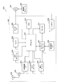
- FIG. 1 is a diagram illustrating an example of a system configuration of a communication system 10 according to an embodiment of the present technology. It is a figure which shows the example of a setting of NAV used as the foundation of this technique. It is a figure which shows the example which shortens the set NAV used as the foundation of this technique. It is a figure showing an example of shortening of NAV by transmission of an invitation frame in an embodiment of this art. It is a figure showing other examples of shortening of NAV by transmission of an invitation frame in an embodiment of this art. It is a figure showing an example of composition of an invitation frame in an embodiment of this art.
- FIG. 38 is a block diagram illustrating an example of a schematic configuration of a car navigation device 920 to which the technology according to the present disclosure can be applied. It is a block diagram which shows an example of a schematic structure of the wireless access point 950 with which the technique which concerns on this indication can be applied.
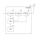
- FIG. 1 is a block diagram illustrating a functional configuration example of the information processing apparatus 100 according to the embodiment of the present technology.
- the information processing apparatus 100 includes a data processing unit 110, a signal processing unit 120, a wireless interface unit 130, an antenna 140, a storage unit 150, and a control unit 160.
- the information processing apparatus 100 can be a fixed or portable information processing apparatus having a wireless communication function.
- the fixed information processing apparatus is an information processing apparatus such as an access point or a base station in a wireless LAN (Local Area Network) system, for example.
- the portable information processing device is an information processing device such as a smartphone, a mobile phone, or a tablet terminal.
- the information processing apparatus 100 is assumed to have a communication function compliant with, for example, IEEE (Institute of Electrical and Electronic Engineers) 802.11 wireless LAN standard.
- IEEE Institute of Electrical and Electronic Engineers 802.11 wireless LAN standard.
- a communication function compliant with the IEEE802.11ax wireless LAN standard can be provided.
- a wireless LAN for example, Wi-Fi (Wireless Fidelity), Wi-Fi Direct, Wi-Fi CERTIFIED Miracast specifications (technical specification name: Wi-Fi Display) can be used. Further, wireless communication using another communication method may be performed.
- the information processing apparatus 100 may be a device that supports, for example, MU-MIMO (Multi User MIMO). In this case, the information processing apparatus 100 can simultaneously transmit to a plurality of devices. The information processing apparatus 100 can receive a CTS (Clear-to-Send) frame from a plurality of devices when transmitting to a plurality of devices simultaneously.
- CTS Carrier-to-Send
- the data processing unit 110 processes various data based on the control of the control unit 160. For example, the data processing unit 110 performs additional processing such as a MAC (Media Access Control) header or an error detection code on data from an upper layer, and generates a packet for wireless transmission. Then, the data processing unit 110 supplies the generated packet to the signal processing unit 120.
- additional processing such as a MAC (Media Access Control) header or an error detection code on data from an upper layer.
- MAC Media Access Control
- error detection code on data from an upper layer
- the data processing unit 110 supplies the generated packet to the signal processing unit 120.
- the data processing unit 110 when receiving data, the data processing unit 110 performs header analysis, packet error detection processing, and the like on the bit string received from the signal processing unit 120, and supplies the processed data to the upper layer. In addition, for example, the data processing unit 110 notifies the control unit 160 of the header analysis result, the packet error detection result, and the like.
- the signal processing unit 120 performs various signal processing based on the control of the control unit 160. For example, at the time of transmission, the signal processing unit 120 encodes input data from the data processing unit 110 based on the coding and modulation scheme set by the control unit 160, and adds a preamble and a PHY header. Then, the signal processing unit 120 supplies the transmission symbol stream obtained by the signal processing to the wireless interface unit 130.
- the signal processing unit 120 detects a preamble and a PHY header for the received symbol stream received from the wireless interface unit 130, performs decoding processing, and supplies the decoded data to the data processing unit 110. For example, the signal processing unit 120 notifies the control unit 160 of the detection result of the PHY header and the like.
- the wireless interface unit 130 is an interface for transmitting and receiving various information by connecting to another information processing apparatus using wireless communication based on the control of the control unit 160. For example, at the time of transmission, the wireless interface unit 130 converts the input from the signal processing unit 120 into an analog signal, performs amplification, filtering, up-conversion to a predetermined frequency, and sends the signal to the antenna 140.
- the wireless interface unit 130 performs reverse processing on the input from the antenna 140 and supplies the processing result to the signal processing unit 120.
- control of the transmission power of data transmitted from the wireless interface unit 130 is performed by the control unit 160.
- the storage unit 150 has a role as a work area for data processing by the control unit 160 and a function as a storage medium for holding various data.
- a storage medium such as a nonvolatile memory, a magnetic disk, an optical disk, or an MO (Magneto Optical) disk can be used.
- the nonvolatile memory for example, EEPROM (Electrically Erasable Programmable Read-Only Memory) or EPROM (Erasable Programmable ROM) can be used.
- the magnetic disk for example, a hard disk or a disk type magnetic disk can be used.
- the optical disc for example, a CD (Compact Disc), a DVD-R (Digital Versatile Disc Recordable), or a BD (Blu-ray (registered trademark) Disc) can be used.
- the control unit 160 controls the reception operation and the transmission operation of each of the data processing unit 110, the signal processing unit 120, and the wireless interface unit 130. For example, the control unit 160 exchanges information between the units, sets communication parameters, and schedules packets in the data processing unit 110.
- control unit 160 causes another communication device to transmit a transmission suppression period shortening (CF_End) frame for shortening a transmission suppression period (NAV (NetworkVAllocation Vector)) that is a period for suppressing frame transmission.
- CF_End transmission suppression period shortening
- NAV NetworkVAllocation Vector
- control unit 160 when receiving the invitation frame, performs control to transmit the CF_End frame based on the invitation frame.
- FIG. 2 is a diagram illustrating an example of a system configuration of the communication system 10 according to the embodiment of the present technology.
- the communication system 10 includes an information processing device (STA A) 210, an information processing device (STA B) 220, an information processing device (STA1) 230, an information processing device (STA2) 240, and an information processing device (STA3) 250.
- the radio wave reach 260 of the information processing apparatus (STA A) 210 is indicated by a dashed circle centering on the information processing apparatus (STA A) 210.
- the radio wave reachable range 270 of the information processing apparatus (STA B) 220 is indicated by a broken circle centering on the information processing apparatus (STA B) 220.
- the information processing apparatus (STA A) 210 transmits a frame to the information processing apparatus (STA B) 220.
- the information processing apparatus (STA2) 240 exists outside the radio wave reach 260 of the information processing apparatus (STA A) 210, the frame from the information processing apparatus (STA A) 210 can be detected. Can not.
- the information processing apparatus (STA2) 240 determines that the radio band is not used and starts frame transmission from the own apparatus. In this case, while the frame is being transmitted from the information processing apparatus (STA A) 210, the frame is also transmitted from the information processing apparatus (STA2) 240.
- the information from the information processing apparatus (STA A) 210 and the frame transmission from the information processing apparatus (STA 2) 240 are performed in the same time zone, the information from the information processing apparatus (STA A) 210 is transmitted.
- the frame and the frame from the information processing apparatus (STA2) 240 collide, and the information processing apparatus (STA B) 220 may fail to receive a desired signal.
- IEEE 802.11 adopts a system called NAV. An example of this is shown in FIG.
- FIG. 3 is a diagram illustrating a setting example of the NAV that is the basis of the present technology.
- the horizontal axis shown in FIG. 3 represents a time axis.
- the data to be transmitted is indicated by a rectangle with the content added to the upper side of the time axis corresponding to the information processing apparatus (STA A) 210 and the information processing apparatus (STA B) 220.
- the detected data is indicated by a rectangle with the contents added to the upper side of the time axis corresponding to the information processing apparatus (STA2) 240.
- FIG. 3 shows an example in which NAVs are respectively set in the information processing device (STA1) 230 and the information processing device (STA2) 240 by the RST frame and the CTS frame transmitted from the information processing device (STA B) 220. .
- the information processing apparatus (STA A) 210 transmits an RTS frame to the information processing apparatus (STA B) 220 before transmitting data addressed to the information processing apparatus (STA B) 220 (301).
- the time for setting the NAV is stored in Duration.
- the NAV based on virtual carrier sense is set for the time stored in the Duration in the RTS frame (310).
- the information processing apparatus (STA B) 220 When the information processing apparatus (STA B) 220 receives the RTS frame, the information processing apparatus (STA B) 220 transmits a CTS frame corresponding to the RTS frame to the information processing apparatus (STA A) 210 (303).
- the duration (transmission suppression time) for setting the NAV is stored in Duration in this CTS frame. Further, in the information processing apparatus (STA B) 220, the NAV based on the virtual carrier sense is set for the time stored in the Duration in the CTS frame (311).
- the RTS frame and the CTS frame are exchanged between the information processing apparatus (STA A) 210 and the information processing apparatus (STA B) 220 (301 and 303).
- the RTS frame and the CTS frame store information for the device (peripheral device) that receives each frame to set a transmission suppression period.
- the NAV is set in the information processing apparatus (STA1) 230. (310). Further, since the information processing apparatus (STA2) 240 can detect the CTS frame transmitted from the information processing apparatus (STA B) 220 (304), the NAV is set in the information processing apparatus (STA2) 240 ( 311).
- the information processing apparatus (STA2) 240 that has received the CTS frame waits until the frame exchange between the information processing apparatus (STA A) 210 and the information processing apparatus (STA B) 220 ends (311). Suppresses transmissions from. For this reason, the above-described packet collision can be avoided.
- the time required for Data transmission varies depending on the surrounding environment of the information processing apparatus (STA A) 210.
- STA B information processing apparatus
- MCS Modulation and Coding scheme
- FIG. 4 is a diagram illustrating an example of shortening the set NAV that is the basis of the present technology.
- the information processing apparatus (STA A) 210 transmits a CF_End frame to the surrounding information processing apparatuses.
- the NAV set in the information processing apparatus can be shortened.
- the information processing apparatus (STA1) 230 detects the CF_End frame (309) and cancels the NAV (310), whereby the NAV (310) is shortened. As a result, the information processing apparatus (STA1) 230 can perform transmission from the own apparatus in the subsequent period. As described above, the radio resource can be effectively used by transmitting the CF_End frame.
- the information processing apparatus (STA2) 240 that cannot receive the CF_End frame from the information processing apparatus (STA A) 210 cannot shorten the set NAV (311). For this reason, the information processing apparatus (STA2) 240 suffers a disadvantage during the period 312 in the figure as compared with the information processing apparatus (STA1) 230.
- the information processing apparatus (STA B) 220 that has received the CF_End frame makes a response to the CF_End frame, so that the NAV can be shortened in the information processing apparatus (STA B) 220.
- the NAV cannot be shortened simultaneously with the information processing apparatus (STA1) 230, and the disadvantage of the information processing apparatus (STA2) 240 is not eliminated.
- the information processing apparatus (STA A) 210 transmits the above-described invitation frame, and invites another information processing apparatus to transmit the CF_End frame.
- a CF_End frame is transmitted from a plurality of information processing apparatuses, and the above disadvantages can be solved.
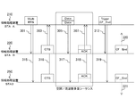
- FIG. 5 is a diagram illustrating an example of shortening the NAV by transmitting an invitation frame in the embodiment of the present technology.
- the information processing apparatus (STA A) 210 sends an invitation frame (Trigger frame) to the information processing apparatus (STA B) 220.
- the Trigger frame is a frame that induces transmission of the CF_End frame.
- the information processing apparatus (STA B) 220 that has received the trigger frame transmits a CF_End frame after a predetermined time has elapsed (314).
- the NAV of the information processing apparatus around the information processing apparatus (STA B) 220 specifically, the information processing apparatus (STA2) 240 can be shortened.
- the information processing apparatus (STA A) 210 that first transmitted the frame for setting the NAV in the transmission of the Data frame for which the NAV is set (the transmission of the RTS frame 301 and 302 in the figure) transmits the Trigger frame. .
- the information processing apparatus (STA1) 210 that has transmitted the Trigger frame can also transmit the CF_End frame after a predetermined time has elapsed (309).
- the NAV of the information processing apparatus around the information processing apparatus (STA A) 210, specifically, the information processing apparatus (STA1) 230 can be shortened.
- the information processing apparatus (STA A) 210 and the information processing apparatus (STA B) 220 simultaneously start transmission of CF_End frames (309 and 314). These are transmitted based on the same transmission rate. Further, the information processing apparatus (STA A) 210 transmits a CF_End frame having the same configuration as the CF_End frame transmitted by the information processing apparatus (STA B) 220.
- a CF_End frame having the same configuration is simultaneously transmitted from a plurality of information processing apparatuses at the same transmission rate, so that it is received as a single CF-End frame in another information processing apparatus. Can be made.
- the information processing apparatus (STA A) 210 can also transmit the Trigger frame to a plurality of information processing apparatuses. This will be described with reference to FIG.
- FIG. 6 is a diagram illustrating another example of shortening the NAV by transmitting an invitation frame in the embodiment of the present technology. This figure shows a case where frames are simultaneously transmitted to a plurality of information processing apparatuses by a spatial / frequency multiplexing sequence.
- the information processing apparatus (STA A) 210 simultaneously transmits a Multi RTS frame instead of the RST frame to the information processing apparatus (STA B) 220 and the information processing apparatus (STA3) 250 (301 and 315).
- the CTS frame is simultaneously transmitted from the information processing apparatus (STA B) 220 and the information processing apparatus (STA3) 250 to the information processing apparatus (STA A) 210 (303 and 316).
- the information processing apparatus (STA A) 210 transmits the Data frame simultaneously to the information processing apparatus (STA B) 220 and the information processing apparatus (STA3) 250 (305 and 317).
- the transmission of the Data frame is performed by spatial multiplexing or frequency multiplexing sequence.
- the information processing apparatus (STA B) 220 and the information processing apparatus (STA 3) 250 simultaneously transmit an ACK frame to the information processing apparatus (STA A) 210 (307 and 318). These ACK frames are transmitted using different channels.
- the information processing apparatus (STA A) 210 that has received these ACK frames transmits the Trigger frame simultaneously to the information processing apparatus (STA B) 220 and the information processing apparatus (STA 3) 250 (312 and 319).
- the information processing apparatus (STA B) 220 and the information processing apparatus (STA3) 250 that have received the Trigger frame simultaneously transmit the CF_End frame (320 and 321).
- FIG. 7 is a diagram illustrating a configuration example of an attracting frame according to the embodiment of the present technology.
- This figure shows a configuration example of the Trigger frame described in FIG.
- the Trigger frame shown in the figure includes a PHY Header 171, a Frame Type 172, a Duration 173, an Rx Address 174, a Tx Address 175, and an Allowed Frame 176.
- the Trigger frame shown in the figure further includes a Triggered STA 177 and an FCS 178.
- Frame Type 172, Duration 173, Rx Address 174, and Tx Address 175 constitute a MAC Header.
- the MAC header stores information (Frame Type) indicating the transmission purpose of the frame.
- information (UL Trigger) indicating that the target information processing apparatus is allowed to communicate in the reverse direction is described.
- PHY Header 171 stores BSS (Basic Service Set), Color, Length, and the like.
- Duration 173 describes duration information for setting the NAV.
- Rx Address 174 address information of an information processing apparatus that should receive the frame is described.
- a broadcast address for broadcast transmission As the address information, a plurality of information processing apparatuses can receive a Trigger frame. That is, in the Trigger frame described with reference to FIG. 6, the broadcast address is described in Rx Address 174.
- Tx Address 175 address information of the information processing apparatus that is the transmission source of the frame is described.
- the Allowed Frame 176 describes the type of frame to be transmitted in the reverse direction.
- a CF_End frame is designated.
- an address (STA ID) 179 of the information processing apparatus that transmits in the reverse direction is described.
- the addresses of the information processing apparatus (STA B) 220 and the information processing apparatus (STA 3) 250 are described.
- FCS 178 stores an error detection code.
- FIG. 8 is a diagram illustrating a configuration example of a transmission suppression period shortening frame according to the embodiment of the present technology. This figure shows a configuration example of the CF_End frame described in FIG.
- the CF_End frame shown in the drawing includes a PHY header 181, a frame type 182, a duration 183, an Rx Address 184, a Tx Address 185, and an FCS 188.
- the Frame Type 182, the Duration 183, the Rx Address 184, and the Tx Address 185 constitute a MAC Header.
- Frame Type 182 describes that the frame is a CF_End frame.
- the value “0” is described in Duration 183.
- Rx Address 184 describes the broadcast address.
- Tx Address 185 for example, the address of the information processing apparatus that has transmitted the Trigger frame is described. This is because a CF_End frame having the same content is transmitted from a plurality of information processing apparatuses. This can be defined by standards, for example.
- PHY Header 181 and FCS 188 are the same as PHY Header 171 and FCS 178 described in FIG.
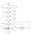
- FIG. 9 is a diagram illustrating an example of a processing procedure of data transmission processing according to the embodiment of the present technology.
- the process in FIG. 10 is a process executed when the information processing apparatus transmits data. Specifically, this is processing executed by the information processing apparatus (STA A) 210 described in FIG.
- the control unit 160 transmits an RTS frame (step S801). Thereby, the transmission suppression period (310 in FIG. 5) is set.
- the control unit 160 waits until a CTS frame is received (step S802).
- the control unit 160 transmits a data frame (step S803).
- the control unit 160 waits until an ACK frame is received (step S804).
- the control unit 160 determines whether there is transmission data (step S805). This can be determined based on, for example, whether there is data to be further sent to the transmission buffer.
- step S805 If there is transmission data (step S805: Yes), the control unit 160 determines whether or not the remaining time of the transmission suppression period is equal to or greater than the threshold 1 (step S806).
- the threshold value 1 is a remaining time threshold value for determining whether or not the transmission and reception of the Data frame and the ACK frame are possible.
- step S806: Yes the control unit 160 executes the processing from step S803 again. If the remaining time is less than the threshold value 1 (step S806: No), the control unit 160 proceeds to the process of step S807. On the other hand, if there is no transmission data in step S805 (step S805: No), the control unit 160 proceeds to the process of step S807.
- step S807 the control unit 160 determines whether or not the remaining time of the transmission suppression period is equal to or greater than the threshold 2 (step S807).
- the threshold value 2 is a remaining time threshold value for determining whether or not the invitation frame and the transmission suppression period shortened frame can be transmitted. If the remaining time is greater than or equal to the threshold 2 (step S807: Yes), the control unit 160 transmits an invitation frame (step S808). Specifically, the Trigger frame described in FIG. 7 is transmitted. Next, the control unit 160 transmits a transmission suppression period shortened frame after a predetermined time (step S809). Specifically, the CF_End frame described in FIG. 8 is transmitted. Here, as the predetermined time, a time determined by a standard can be applied. Thereafter, the control unit 160 ends the data transmission process.
- step S807 when the remaining time of the transmission suppression period is less than the threshold 2 in step S807 (step S807: No), the control unit 160 skips the processes of steps S808 and S809 and ends the data transmission process.
- FIG. 10 is a diagram illustrating an example of a processing procedure of response processing according to the embodiment of the present technology.
- the process in FIG. 5 is a process performed by the information processing apparatus that has received the RTS frame. Specifically, this is a process executed by the information processing apparatus (STA B) 220 described in FIG.
- control unit 160 waits until an RTS frame is received (step S851).
- the control unit 160 transmits the CTS frame (step S852). Thereby, a transmission suppression period (311 in FIG. 5) is set.
- control unit 160 receives the Data frame (step S853).
- control unit 160 transmits an ACK frame (step S854).
- control unit 160 determines whether an invitation frame (Trigger frame) has been received (step S858).
- the control unit 160 transmits a transmission suppression period shortened frame (CF_End frame) after a predetermined time (step S859), and ends the response process.
- CF_End frame transmission suppression period shortened frame
- the information processing apparatus can transmit the CF_End frame.
- step S858 determines whether or not the transmission suppression period has elapsed (step S855).
- step S855: No the control unit 160 executes the processing from step S858 again.
- step S855: Yes the control unit 160 ends the response process.
- the transmission suppression period set in the other information processing apparatus can be shortened equally, and the inequality in the use of radio resources can be eliminated.
- the information processing apparatus 100 is a smartphone, a tablet PC (Personal Computer), a notebook PC, a mobile terminal such as a portable game terminal or a digital camera, a fixed terminal such as a television receiver, a printer, a digital scanner, or a network storage, or You may implement
- the information processing apparatus 100 is a terminal (also referred to as an MTC (Machine Type Communication) terminal) that performs M2M (Machine To Machine) communication, such as a smart meter, a vending machine, a remote monitoring apparatus, or a POS (Point Of Sale) terminal. It may be realized as.
- the information processing apparatus 100 may be a wireless communication module (for example, an integrated circuit module configured by one die) mounted on these terminals.
- the information processing apparatus 100 may be realized as a wireless LAN access point (also referred to as a wireless base station) having a router function or not having a router function. Further, the information processing apparatus 100 and each information processing apparatus (STA) may be realized as a mobile wireless LAN router. Furthermore, the information processing apparatus 100 may be a wireless communication module (for example, an integrated circuit module configured by one die) mounted on these apparatuses.
- a wireless LAN access point also referred to as a wireless base station
- STA information processing apparatus
- the information processing apparatus 100 may be realized as a mobile wireless LAN router.
- the information processing apparatus 100 may be a wireless communication module (for example, an integrated circuit module configured by one die) mounted on these apparatuses.
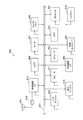
- FIG. 11 is a block diagram illustrating an example of a schematic configuration of a smartphone 900 to which the technology according to the present disclosure can be applied.
- the smartphone 900 includes a processor 901, a memory 902, a storage 903, an external connection interface 904, a camera 906, a sensor 907, a microphone 908, an input device 909, a display device 910, a speaker 911, a wireless communication interface 913, an antenna switch 914, an antenna 915, A bus 917, a battery 918, and an auxiliary controller 919 are provided.
- the processor 901 may be, for example, a CPU (Central Processing Unit) or a SoC (System on Chip), and controls the functions of the application layer and other layers of the smartphone 900.
- the memory 902 includes a RAM (Random Access Memory) and a ROM (Read Only Memory), and stores programs and data executed by the processor 901.
- the storage 903 can include a storage medium such as a semiconductor memory or a hard disk.
- the external connection interface 904 is an interface for connecting an external device such as a memory card or a USB (Universal Serial Bus) device to the smartphone 900.
- the camera 906 includes, for example, an image sensor such as a CCD (Charge Coupled Device) or a CMOS (Complementary Metal Oxide Semiconductor), and generates a captured image.
- the sensor 907 may include a sensor group such as a positioning sensor, a gyro sensor, a geomagnetic sensor, and an acceleration sensor.
- the microphone 908 converts sound input to the smartphone 900 into an audio signal.
- the input device 909 includes, for example, a touch sensor that detects a touch on the screen of the display device 910, a keypad, a keyboard, a button, or a switch, and receives an operation or information input from a user.
- the display device 910 has a screen such as a liquid crystal display (LCD) or an organic light emitting diode (OLED) display, and displays an output image of the smartphone 900.
- the speaker 911 converts an audio signal output from the smartphone 900 into audio.
- the wireless communication interface 913 supports one or more wireless LAN standards such as IEEE802.11a, 11b, 11g, 11n, 11ac, and 11ad, and executes wireless communication.
- the wireless communication interface 913 can communicate with other devices via a wireless LAN access point in the infrastructure mode.
- the wireless communication interface 913 can directly communicate with other devices in the ad-hoc mode or the direct communication mode such as Wi-Fi Direct.
- Wi-Fi Direct unlike the ad hoc mode, one of two terminals operates as an access point, but communication is performed directly between the terminals.
- the wireless communication interface 913 can typically include a baseband processor, an RF (Radio Frequency) circuit, a power amplifier, and the like.
- the wireless communication interface 913 may be a one-chip module in which a memory that stores a communication control program, a processor that executes the program, and related circuits are integrated.
- the wireless communication interface 913 may support other types of wireless communication methods such as a short-range wireless communication method, a proximity wireless communication method, or a cellular communication method in addition to the wireless LAN method.
- the antenna switch 914 switches the connection destination of the antenna 915 among a plurality of circuits (for example, circuits for different wireless communication schemes) included in the wireless communication interface 913.
- the antenna 915 includes a single antenna element or a plurality of antenna elements (for example, a plurality of antenna elements constituting a MIMO antenna), and is used for transmission and reception of radio signals by the radio communication interface 913.
- the smartphone 900 is not limited to the example in FIG. 11, and may include a plurality of antennas (for example, an antenna for a wireless LAN and an antenna for a proximity wireless communication method). In that case, the antenna switch 914 may be omitted from the configuration of the smartphone 900.
- the bus 917 connects the processor 901, memory 902, storage 903, external connection interface 904, camera 906, sensor 907, microphone 908, input device 909, display device 910, speaker 911, wireless communication interface 913, and auxiliary controller 919 to each other.
- the battery 918 supplies power to each block of the smartphone 900 illustrated in FIG. 11 through a power supply line partially illustrated by a broken line in the drawing.
- the auxiliary controller 919 operates the minimum necessary functions of the smartphone 900 in the sleep mode.
- control unit 160 described with reference to FIG. 1 may be implemented in the wireless communication interface 913.
- at least a part of these functions may be implemented in the processor 901 or the auxiliary controller 919.
- the control unit 160 transmits an invitation frame it is possible to improve the utilization efficiency of radio resources and reduce the power consumption of the battery 918.
- the smartphone 900 may operate as a wireless access point (software AP) when the processor 901 executes the access point function at the application level. Further, the wireless communication interface 913 may have a wireless access point function. [2-2. Second application example]
- FIG. 12 is a block diagram illustrating an example of a schematic configuration of a car navigation device 920 to which the technology according to the present disclosure can be applied.
- the car navigation apparatus 920 includes a processor 921, a memory 922, a GPS (Global Positioning System) module 924, a sensor 925, a data interface 926, a content player 927, a storage medium interface 928, an input device 929, a display device 930, a speaker 931, and wireless communication.
- An interface 933, an antenna switch 934, an antenna 935, and a battery 938 are provided.
- the processor 921 may be a CPU or SoC, for example, and controls the navigation function and other functions of the car navigation device 920.
- the memory 922 includes RAM and ROM, and stores programs and data executed by the processor 921.
- the GPS module 924 measures the position (for example, latitude, longitude, and altitude) of the car navigation device 920 using GPS signals received from GPS satellites.
- the sensor 925 may include a sensor group such as a gyro sensor, a geomagnetic sensor, and an atmospheric pressure sensor.
- the data interface 926 is connected to the in-vehicle network 941 through a terminal (not shown), for example, and acquires data generated on the vehicle side such as vehicle speed data.
- the content player 927 reproduces content stored in a storage medium (for example, CD or DVD) inserted into the storage medium interface 928.
- the input device 929 includes, for example, a touch sensor, a button, or a switch that detects a touch on the screen of the display device 930, and receives an operation or information input from the user.
- the display device 930 has a screen such as an LCD or an OLED display, and displays a navigation function or an image of content to be reproduced.
- the speaker 931 outputs the navigation function or the audio of the content to be played back.
- the wireless communication interface 933 supports one or more of wireless LAN standards such as IEEE802.11a, 11b, 11g, 11n, 11ac, and 11ad, and executes wireless communication.
- the wireless communication interface 933 can communicate with other devices via a wireless LAN access point in the infrastructure mode.
- the wireless communication interface 933 can directly communicate with other devices in an ad hoc mode or a direct communication mode such as Wi-Fi Direct.
- the wireless communication interface 933 may typically include a baseband processor, an RF circuit, a power amplifier, and the like.
- the wireless communication interface 933 may be a one-chip module in which a memory that stores a communication control program, a processor that executes the program, and related circuits are integrated.
- the wireless communication interface 933 may support other types of wireless communication systems such as a short-range wireless communication system, a proximity wireless communication system, or a cellular communication system.
- the antenna switch 934 switches the connection destination of the antenna 935 among a plurality of circuits included in the wireless communication interface 933.
- the antenna 935 includes a single antenna element or a plurality of antenna elements, and is used for transmission and reception of a radio signal by the radio communication interface 933.
- the car navigation device 920 is not limited to the example of FIG. 12, and may include a plurality of antennas. In that case, the antenna switch 934 may be omitted from the configuration of the car navigation device 920.
- the battery 938 supplies power to each block of the car navigation apparatus 920 shown in FIG. 12 through a power supply line partially shown by a broken line in the drawing. Further, the battery 938 stores electric power supplied from the vehicle side.
- control unit 160 described with reference to FIG. 1 may be implemented in the wireless communication interface 933. Further, at least a part of these functions may be implemented in the processor 921. For example, the use efficiency of radio resources can be improved by the car navigation device 920 transmitting an invitation frame.
- the wireless communication interface 933 may operate as the information processing apparatus 100 described above and provide a wireless connection to a terminal of a user who gets on the vehicle.
- the technology according to the present disclosure may be realized as an in-vehicle system (or vehicle) 940 including one or more blocks of the car navigation device 920 described above, an in-vehicle network 941, and a vehicle side module 942.
- vehicle-side module 942 generates vehicle-side data such as vehicle speed, engine speed, or failure information, and outputs the generated data to the in-vehicle network 941.
- FIG. 13 is a block diagram illustrating an example of a schematic configuration of a wireless access point 950 to which the technology according to the present disclosure can be applied.
- the wireless access point 950 includes a controller 951, a memory 952, an input device 954, a display device 955, a network interface 957, a wireless communication interface 963, an antenna switch 964, and an antenna 965.
- the controller 951 may be a CPU or a DSP (Digital Signal Processor), for example, and various functions (for example, access restriction, routing, encryption, firewall) of the IP (Internet Protocol) layer and higher layers of the wireless access point 950 And log management).
- the memory 952 includes a RAM and a ROM, and stores programs executed by the controller 951 and various control data (for example, a terminal list, a routing table, an encryption key, security settings, and a log).
- the input device 954 includes, for example, a button or a switch and receives an operation from the user.
- the display device 955 includes an LED lamp and the like, and displays the operation status of the wireless access point 950.
- the network interface 957 is a wired communication interface for the wireless access point 950 to connect to the wired communication network 958.
- the network interface 957 may have a plurality of connection terminals.
- the wired communication network 958 may be a LAN such as Ethernet (registered trademark), or may be a WAN (Wide Area Network).
- the wireless communication interface 963 supports one or more of wireless LAN standards such as IEEE802.11a, 11b, 11g, 11n, 11ac, and 11ad, and provides a wireless connection as an access point to nearby terminals.
- the wireless communication interface 963 typically includes a baseband processor, an RF circuit, a power amplifier, and the like.
- the wireless communication interface 963 may be a one-chip module in which a memory that stores a communication control program, a processor that executes the program, and related circuits are integrated.
- the antenna switch 964 switches the connection destination of the antenna 965 among a plurality of circuits included in the wireless communication interface 963.
- the antenna 965 includes a single antenna element or a plurality of antenna elements, and is used for transmission and reception of a radio signal by the radio communication interface 963.
- the control unit 160 described with reference to FIG. 1 may be implemented in the wireless communication interface 963.
- at least a part of these functions may be implemented in the controller 951.
- the utilization efficiency of wireless resources can be improved.
- the processing procedure described in the above embodiment may be regarded as a method having a series of these procedures, and a program for causing a computer to execute these series of procedures or a recording medium storing the program. You may catch it.
- a recording medium for example, a CD (Compact Disc), an MD (MiniDisc), a DVD (Digital Versatile Disc), a memory card, a Blu-ray disc (Blu-ray (registered trademark) Disc), or the like can be used.
- An information processing apparatus including a control unit that transmits an invitation frame for causing another communication device to transmit a transmission suppression period shortening frame for shortening a transmission suppression period.
- the information processing apparatus according to (1) wherein the control unit transmits the transmission suppression period shortening frame to another communication device after transmitting the invitation frame.
- the control unit transmits the transmission suppression period shortening frame having the same configuration as the transmission suppression period shortening frame that is attracted and transmitted by the transmitted invitation frame.
- the control unit transmits the transmission suppression period shortened frame simultaneously with the transmission suppression period shortened frame that is attracted and transmitted by the transmitted invitation frame. apparatus.
- the control unit transmits the transmission suppression period shortened frame based on the same transmission rate as the transmission suppression period shortened frame that is attracted and transmitted by the transmitted invitation frame. ).
- the control unit transmits the attraction frame when transmitting a frame that sets the transmission suppression period first in data transmission in the transmission suppression period. The information processing apparatus described.
- the information processing apparatus according to any one of (1) to (7), wherein the control unit performs control to transmit the attraction frame including information included in a trigger frame.
- the control unit When receiving an invitation frame for inviting transmission of a transmission suppression period shortened frame for shortening the transmission suppression period, the control unit transmits the transmission suppression period shortened frame based on the invitation frame.
- Information processing device (10) The information processing according to (9), wherein the control unit transmits the transmission suppression period shortened frame when the invitation frame is received from another communication device that has transmitted the frame for setting the transmission suppression period. apparatus. (11) The information processing apparatus according to (9) or (10), wherein the control unit transmits the transmission suppression period shortened frame when the invitation frame including information included in a trigger frame is received.
- a first information processing apparatus including a first control unit that transmits an invitation frame for causing another communication device to transmit a transmission suppression period shortening frame for shortening the transmission suppression period;
- a communication system comprising: a second information processing apparatus including a second control unit that transmits the transmission suppression period shortened frame based on the invitation frame when the transmitted invitation frame is received.
- An information processing method including a control procedure for transmitting an invitation frame for causing another communication device to transmit a transmission suppression period shortening frame for shortening a transmission suppression period.
- a control procedure for transmitting the transmission suppression period shortened frame based on the invitation frame is provided.
- a control procedure for transmitting the transmission suppression period shortened frame based on the invitation frame to a computer The program to be executed.
Abstract
Description
1.第1の実施の形態(送信抑制期間短縮フレームを他の通信機器に送信させるための誘引フレームを送信する場合の例)
2.応用例
[情報処理装置の機能構成例]
図1は、本技術の実施の形態における情報処理装置100の機能構成例を示すブロック図である。
図2は、本技術の実施の形態における通信システム10のシステム構成の一例を示す図である。
図3は、本技術の基礎となるNAVの設定例を示す図である。なお、図3に示す横軸は、時間軸を表す。また、図3において、情報処理装置(STA A)210および情報処理装置(STA B)220に対応する時間軸の上側には、送信対象となるデータを内部にその内容を付した矩形で示す。また、情報処理装置(STA2)240に対応する時間軸の上側には、検出したデータを内部にその内容を付した矩形で示す。
図4は、本技術の基礎となる設定されたNAVを短縮する例を示す図である。同図において、情報処理装置(STA B)220からACKフレームが送信(307)された後、情報処理装置(STA A)210は、CF_Endフレームを周囲の情報処理装置に対して送信し、これらの情報処理装置に設定されているNAVを短縮することができる。
図5は、本技術の実施の形態における誘引フレームの送信によるNAVの短縮の一例を示す図である。同図において、情報処理装置(STA B)220からACKが送信(307)された後、情報処理装置(STA A)210は、誘引フレーム(Triggerフレーム)を情報処理装置(STA B)220に対して送信する(312)。Triggerフレームは、CF_Endフレームの送信を誘引するフレームである。Triggerフレームを受信した情報処理装置(STA B)220は、所定の時間経過後にCF_Endフレームを送信する(314)。これにより、情報処理装置(STA B)220の周囲の情報処理装置、具体的には、情報処理装置(STA2)240のNAVを短縮することができる。
図7は、本技術の実施の形態における誘引フレームの構成例を示す図である。同図は、図6において説明したTriggerフレームの構成例を表したものである。同図のTriggerフレームは、PHY Header171と、Frame Type172と、Duration173と、Rx Address174と、Tx Address175と、Allowed Frame176とを備える。また、同図のTriggerフレームは、Triggered STA177と、FCS178とをさらに備える。
図8は、本技術の実施の形態における送信抑制期間短縮フレームの構成例を示す図である。同図は、図5において説明したCF_Endフレームの構成例を表したものである。同図のCF_Endフレームは、PHY Header181と、Frame Type182と、Duration183と、Rx Address184と、Tx Address185と、FCS188とを備える。
図9は、本技術の実施の形態におけるデータ送信処理の処理手順の一例を示す図である。同図の処理は、情報処理装置がデータの送信を行う際に実行される処理である。具体的には、図5において説明した情報処理装置(STA A)210が実行する処理である。
図10は、本技術の実施の形態における応答処理の処理手順の一例を示す図である。同図の処理は、RTSフレームを受信した情報処理装置が行う処理である。具体的には、図5において説明した情報処理装置(STA B)220が実行する処理である。
本開示に係る技術は、様々な製品へ応用可能である。例えば、情報処理装置100は、スマートフォン、タブレットPC(Personal Computer)、ノートPC、携帯型ゲーム端末若しくはデジタルカメラなどのモバイル端末、テレビジョン受像機、プリンタ、デジタルスキャナ若しくはネットワークストレージなどの固定端末、又はカーナビゲーション装置などの車載端末として実現されてもよい。また、情報処理装置100は、スマートメータ、自動販売機、遠隔監視装置又はPOS(Point Of Sale)端末などの、M2M(Machine To Machine)通信を行う端末(MTC(Machine Type Communication)端末ともいう)として実現されてもよい。さらに、情報処理装置100は、これら端末に搭載される無線通信モジュール(例えば、1つのダイで構成される集積回路モジュール)であってもよい。
図11は、本開示に係る技術が適用され得るスマートフォン900の概略的な構成の一例を示すブロック図である。スマートフォン900は、プロセッサ901、メモリ902、ストレージ903、外部接続インターフェース904、カメラ906、センサ907、マイクロフォン908、入力デバイス909、表示デバイス910、スピーカ911、無線通信インターフェース913、アンテナスイッチ914、アンテナ915、バス917、バッテリー918及び補助コントローラ919を備える。
[2-2.第2の応用例]
図13は、本開示に係る技術が適用され得る無線アクセスポイント950の概略的な構成の一例を示すブロック図である。無線アクセスポイント950は、コントローラ951、メモリ952、入力デバイス954、表示デバイス955、ネットワークインタフェース957、無線通信インターフェース963、アンテナスイッチ964及びアンテナ965を備える。
(1)送信抑制期間を短縮するための送信抑制期間短縮フレームを他の通信機器に送信させるための誘引フレームを送信する制御部を具備する情報処理装置。
(2)前記制御部は、前記誘引フレームの送信の後に前記送信抑制期間短縮フレームを他の通信機器に対して送信する前記(1)に記載の情報処理装置。
(3)前記制御部は、前記送信された誘引フレームにより誘引されて送信される送信抑制期間短縮フレームと同一の構成の前記送信抑制期間短縮フレームを送信する前記(2)に記載の情報処理装置。
(4)前記制御部は、前記送信された誘引フレームにより誘引されて送信される送信抑制期間短縮フレームと同時に前記送信抑制期間短縮フレームを送信する前記(2)または(3)に記載の情報処理装置。
(5)前記制御部は、前記送信された誘引フレームにより誘引されて送信される送信抑制期間短縮フレームと同一の送信レートに基づいて前記送信抑制期間短縮フレームを送信する前記(2)から(4)のいずれかに記載の情報処理装置。
(6)前記制御部は、前記誘引フレームを複数の他の情報処理装置に対してブロードキャスト送信する前記(1)から(5)のいずれかに記載の情報処理装置。
(7)前記制御部は、前記送信抑制期間におけるデータの送信において最初に前記送信抑制期間を設定するフレームを送信した場合に前記誘引フレームを送信する前記(1)から(6)のいずれかに記載の情報処理装置。
(8)前記制御部は、前記誘引フレームにトリガフレームに含まれる情報を含めて送信する制御を行う前記(1)から(7)のいずれかに記載の情報処理装置。
(9)送信抑制期間を短縮するための送信抑制期間短縮フレームの送信を誘引するための誘引フレームを受信した場合に当該誘引フレームに基づいて前記送信抑制期間短縮フレームを送信する制御部を具備する情報処理装置。
(10)前記制御部は、前記送信抑制期間を設定するフレームを送信した他の通信機器から前記誘引フレームを受信した場合に前記送信抑制期間短縮フレームを送信する前記(9)に記載の情報処理装置。
(11)前記制御部は、トリガフレームに含まれる情報を含む前記誘引フレームを受信した場合に前記送信抑制期間短縮フレームを送信する前記(9)または(10)に記載の情報処理装置。
(12)送信抑制期間を短縮するための送信抑制期間短縮フレームを他の通信機器に送信させるための誘引フレームを送信する第1の制御部を備える第1の情報処理装置と、
前記送信された誘引フレームを受信した場合に当該誘引フレームに基づいて前記送信抑制期間短縮フレームを送信する第2の制御部を備える第2の情報処理装置と
を具備する通信システム。
(13)送信抑制期間を短縮するための送信抑制期間短縮フレームを他の通信機器に送信させるための誘引フレームを送信する制御手順を具備する情報処理方法。
(14)送信抑制期間を短縮するための送信抑制期間短縮フレームの送信を誘引するための誘引フレームを受信した場合に当該誘引フレームに基づいて前記送信抑制期間短縮フレームを送信する制御手順を具備する情報処理方法。
(15)送信抑制期間を短縮するための送信抑制期間短縮フレームを他の通信機器に送信させるための誘引フレームを送信する制御手順をコンピュータに実行させるプログラム。
(16)送信抑制期間を短縮するための送信抑制期間短縮フレームの送信を誘引するための誘引フレームを受信した場合に当該誘引フレームに基づいて前記送信抑制期間短縮フレームを送信する制御手順をコンピュータに実行させるプログラム。
100、210、220、230、240、250 情報処理装置
110 データ処理部
120 信号処理部
130 無線インターフェース部
140 アンテナ
150 記憶部
160 制御部
900 スマートフォン
901 プロセッサ
902 メモリ
903 ストレージ
904 外部接続インターフェース
906 カメラ
907 センサ
908 マイクロフォン
909 入力デバイス
910 表示デバイス
911 スピーカ
913 無線通信インターフェース
914 アンテナスイッチ
915 アンテナ
917 バス
918 バッテリー
919 補助コントローラ
920 カーナビゲーション装置
921 プロセッサ
922 メモリ
924 GPSモジュール
925 センサ
926 データインタフェース
927 コンテンツプレーヤ
928 記憶媒体インターフェース
929 入力デバイス
930 表示デバイス
931 スピーカ
933 無線通信インターフェース
934 アンテナスイッチ
935 アンテナ
938 バッテリー
941 車載ネットワーク
942 車両側モジュール
950 無線アクセスポイント
951 コントローラ
952 メモリ
954 入力デバイス
955 表示デバイス
957 ネットワークインタフェース
958 有線通信ネットワーク
963 無線通信インターフェース
964 アンテナスイッチ
965 アンテナ
Claims (16)
- 送信抑制期間を短縮するための送信抑制期間短縮フレームを他の通信機器に送信させるための誘引フレームを送信する制御部を具備する情報処理装置。
- 前記制御部は、前記誘引フレームの送信の後に前記送信抑制期間短縮フレームを他の通信機器に対して送信する請求項1記載の情報処理装置。
- 前記制御部は、前記送信された誘引フレームにより誘引されて送信される送信抑制期間短縮フレームと同一の構成の前記送信抑制期間短縮フレームを送信する請求項2記載の情報処理装置。
- 前記制御部は、前記送信された誘引フレームにより誘引されて送信される送信抑制期間短縮フレームと同時に前記送信抑制期間短縮フレームを送信する請求項2記載の情報処理装置。
- 前記制御部は、前記送信された誘引フレームにより誘引されて送信される送信抑制期間短縮フレームと同一の送信レートに基づいて前記送信抑制期間短縮フレームを送信する請求項2記載の情報処理装置。
- 前記制御部は、前記誘引フレームを複数の他の情報処理装置に対してブロードキャスト送信する請求項1記載の情報処理装置。
- 前記制御部は、前記送信抑制期間におけるデータの送信において最初に前記送信抑制期間を設定するフレームを送信した場合に前記誘引フレームを送信する請求項1記載の情報処理装置。
- 前記制御部は、前記誘引フレームにトリガフレームに含まれる情報を含めて送信する制御を行う請求項1記載の情報処理装置。
- 送信抑制期間を短縮するための送信抑制期間短縮フレームの送信を誘引するための誘引フレームを受信した場合に当該誘引フレームに基づいて前記送信抑制期間短縮フレームを送信する制御部を具備する情報処理装置。
- 前記制御部は、前記送信抑制期間を設定するフレームを送信した他の通信機器から前記誘引フレームを受信した場合に前記送信抑制期間短縮フレームを送信する請求項9記載の情報処理装置。
- 前記制御部は、トリガフレームに含まれる情報を含む前記誘引フレームを受信した場合に前記送信抑制期間短縮フレームを送信する請求項9記載の情報処理装置。
- 送信抑制期間を短縮するための送信抑制期間短縮フレームを他の通信機器に送信させるための誘引フレームを送信する第1の制御部を備える第1の情報処理装置と、
前記送信された誘引フレームを受信した場合に当該誘引フレームに基づいて前記送信抑制期間短縮フレームを送信する第2の制御部を備える第2の情報処理装置と
を具備する通信システム。 - 送信抑制期間を短縮するための送信抑制期間短縮フレームを他の通信機器に送信させるための誘引フレームを送信する制御手順を具備する情報処理方法。
- 送信抑制期間を短縮するための送信抑制期間短縮フレームの送信を誘引するための誘引フレームを受信した場合に当該誘引フレームに基づいて前記送信抑制期間短縮フレームを送信する制御手順を具備する情報処理方法。
- 送信抑制期間を短縮するための送信抑制期間短縮フレームを他の通信機器に送信させるための誘引フレームを送信する制御手順をコンピュータに実行させるプログラム。
- 送信抑制期間を短縮するための送信抑制期間短縮フレームの送信を誘引するための誘引フレームを受信した場合に当該誘引フレームに基づいて前記送信抑制期間短縮フレームを送信する制御手順をコンピュータに実行させるプログラム。
Priority Applications (9)
| Application Number | Priority Date | Filing Date | Title |
|---|---|---|---|
| EP20191627.7A EP3758432A1 (en) | 2016-02-25 | 2016-12-21 | Nav reduction |
| MYPI2018702349A MY192680A (en) | 2016-02-25 | 2016-12-21 | Information processing device, communication system, information processing method, and program |
| US16/074,161 US10952244B2 (en) | 2016-02-25 | 2016-12-21 | Information processing apparatus, communication system, information processing method, and program |
| KR1020187023117A KR20180119567A (ko) | 2016-02-25 | 2016-12-21 | 정보 처리 장치, 통신 시스템, 정보 처리 방법 및 프로그램 |
| CN201680082056.3A CN108702785B (zh) | 2016-02-25 | 2016-12-21 | 信息处理装置、通信系统、信息处理方法和计算机可读介质 |
| EP16891664.1A EP3422792B1 (en) | 2016-02-25 | 2016-12-21 | Information processing device, communication system, information processing method, and program |
| CA3013424A CA3013424A1 (en) | 2016-02-25 | 2016-12-21 | Information processing apparatus, communication system, information processing method, and program |
| PH12018501774A PH12018501774A1 (en) | 2016-02-25 | 2018-08-20 | Information processing device, communication system, information processing method, and program |
| US17/179,431 US11627602B2 (en) | 2016-02-25 | 2021-02-19 | Information processing apparatus, communication system, information processing method, and program |
Applications Claiming Priority (2)
| Application Number | Priority Date | Filing Date | Title |
|---|---|---|---|
| JP2016034687A JP2017152983A (ja) | 2016-02-25 | 2016-02-25 | 情報処理装置、通信システム、情報処理方法およびプログラム |
| JP2016-034687 | 2016-02-25 |
Related Child Applications (2)
| Application Number | Title | Priority Date | Filing Date |
|---|---|---|---|
| US16/074,161 A-371-Of-International US10952244B2 (en) | 2016-02-25 | 2016-12-21 | Information processing apparatus, communication system, information processing method, and program |
| US17/179,431 Continuation US11627602B2 (en) | 2016-02-25 | 2021-02-19 | Information processing apparatus, communication system, information processing method, and program |
Publications (1)
| Publication Number | Publication Date |
|---|---|
| WO2017145509A1 true WO2017145509A1 (ja) | 2017-08-31 |
Family
ID=59684992
Family Applications (1)
| Application Number | Title | Priority Date | Filing Date |
|---|---|---|---|
| PCT/JP2016/088021 WO2017145509A1 (ja) | 2016-02-25 | 2016-12-21 | 情報処理装置、通信システム、情報処理方法およびプログラム |
Country Status (9)
| Country | Link |
|---|---|
| US (2) | US10952244B2 (ja) |
| EP (2) | EP3758432A1 (ja) |
| JP (1) | JP2017152983A (ja) |
| KR (1) | KR20180119567A (ja) |
| CN (1) | CN108702785B (ja) |
| CA (1) | CA3013424A1 (ja) |
| MY (1) | MY192680A (ja) |
| PH (1) | PH12018501774A1 (ja) |
| WO (1) | WO2017145509A1 (ja) |
Families Citing this family (3)
| Publication number | Priority date | Publication date | Assignee | Title |
|---|---|---|---|---|
| JP2017152983A (ja) | 2016-02-25 | 2017-08-31 | ソニー株式会社 | 情報処理装置、通信システム、情報処理方法およびプログラム |
| CN111366890B (zh) * | 2018-12-25 | 2022-05-31 | 任子行网络技术股份有限公司 | 一种基于wifi的对手机测向方法和系统 |
| US11856605B2 (en) | 2020-06-12 | 2023-12-26 | Huawei Technologies Co., Ltd. | Medium access control support for heterogenous physical layer data unit multiplexing |
Citations (2)
| Publication number | Priority date | Publication date | Assignee | Title |
|---|---|---|---|---|
| JP2009523371A (ja) * | 2006-01-10 | 2009-06-18 | コネクサント システムズ、インク | 対称送信機会(txop)切断処理 |
| US20120327870A1 (en) * | 2011-06-24 | 2012-12-27 | Interdigital Patent Holdings, Inc. | Method and apparatus for supporting wideband and multiple bandwidth transmission protocols |
Family Cites Families (18)
| Publication number | Priority date | Publication date | Assignee | Title |
|---|---|---|---|---|
| US7852823B2 (en) * | 2001-09-17 | 2010-12-14 | Sharp Kabushiki Kaisha | Communication management method, communication terminal, communication management program, recording medium containing the communication management program, and communication system |
| US20040151146A1 (en) * | 2003-01-30 | 2004-08-05 | Hammerschmidt Joachim S. | Multi-branch OFDM transceiver |
| US7436790B2 (en) * | 2004-03-25 | 2008-10-14 | Research In Motion Limited | Wireless access point methods and apparatus for reduced power consumption and cost |
| KR100608006B1 (ko) * | 2004-08-31 | 2006-08-02 | 삼성전자주식회사 | 무선랜상에서 데이터를 전송하는 방법, 액세스 포인트장치 및 스테이션 장치 |
| US7796566B2 (en) * | 2005-06-22 | 2010-09-14 | Texas Instruments Incorporated | Methods and apparatus to perform dynamic channel management and dynamic bandwidth changes in wireless local area networks |
| US8031661B2 (en) * | 2005-11-08 | 2011-10-04 | Intellectual Ventures I Llc | Symmetric transmit opportunity (TXOP) truncation |
| WO2010064766A1 (en) * | 2008-12-01 | 2010-06-10 | Lg Electronics Inc. | Method and device for transmission opportunity truncation |
| JP2010206574A (ja) * | 2009-03-04 | 2010-09-16 | Sony Corp | 通信装置及び通信方法、コンピューター・プログラム、並びに通信システム |
| JP5391816B2 (ja) | 2009-05-08 | 2014-01-15 | ソニー株式会社 | 通信装置及び通信方法、コンピューター・プログラム、並びに通信システム |
| JP5413071B2 (ja) * | 2009-05-08 | 2014-02-12 | ソニー株式会社 | 通信装置及び通信方法、コンピューター・プログラム、並びに通信システム |
| US9807796B2 (en) * | 2011-09-02 | 2017-10-31 | Qualcomm Incorporated | Systems and methods for resetting a network station |
| US9345026B2 (en) * | 2012-07-09 | 2016-05-17 | Qualcomm Incorporated | Methods and apparatus for requested reverse direction protocol |
| GB2507278A (en) * | 2012-10-23 | 2014-04-30 | Broadcom Corp | Generating a control message frame to instruct the end of a contention-free period |
| WO2016200182A1 (ko) * | 2015-06-10 | 2016-12-15 | 엘지전자 주식회사 | 무선랜 시스템에서 nav를 관리하는 방법 및 이를 위한 장치 |
| US10492221B1 (en) * | 2015-06-25 | 2019-11-26 | Marvell International Ltd. | Methods and apparatus for protecting transmissions in a wireless communication network |
| US10841931B2 (en) * | 2015-06-26 | 2020-11-17 | Wilus Institute Of Standards And Technology Inc. | Wireless communication method for uplink multiple-user transmission schedule and wireless communication terminal using the method |
| US10181996B2 (en) * | 2016-02-12 | 2019-01-15 | Intel IP Corporation | Trigger frame recovery |
| JP2017152983A (ja) | 2016-02-25 | 2017-08-31 | ソニー株式会社 | 情報処理装置、通信システム、情報処理方法およびプログラム |
-
2016
- 2016-02-25 JP JP2016034687A patent/JP2017152983A/ja active Pending
- 2016-12-21 CA CA3013424A patent/CA3013424A1/en active Pending
- 2016-12-21 EP EP20191627.7A patent/EP3758432A1/en active Pending
- 2016-12-21 CN CN201680082056.3A patent/CN108702785B/zh active Active
- 2016-12-21 MY MYPI2018702349A patent/MY192680A/en unknown
- 2016-12-21 EP EP16891664.1A patent/EP3422792B1/en active Active
- 2016-12-21 US US16/074,161 patent/US10952244B2/en active Active
- 2016-12-21 WO PCT/JP2016/088021 patent/WO2017145509A1/ja active Application Filing
- 2016-12-21 KR KR1020187023117A patent/KR20180119567A/ko not_active Application Discontinuation
-
2018
- 2018-08-20 PH PH12018501774A patent/PH12018501774A1/en unknown
-
2021
- 2021-02-19 US US17/179,431 patent/US11627602B2/en active Active
Patent Citations (2)
| Publication number | Priority date | Publication date | Assignee | Title |
|---|---|---|---|---|
| JP2009523371A (ja) * | 2006-01-10 | 2009-06-18 | コネクサント システムズ、インク | 対称送信機会(txop)切断処理 |
| US20120327870A1 (en) * | 2011-06-24 | 2012-12-27 | Interdigital Patent Holdings, Inc. | Method and apparatus for supporting wideband and multiple bandwidth transmission protocols |
Non-Patent Citations (2)
| Title |
|---|
| KIM, JEONGKI ET AL.: "MU TXOP truncation", IEEE 802.11-15/1067R0, 13 September 2015 (2015-09-13), pages 1 - 16, XP055530316, Retrieved from the Internet <URL:https://mentor.ieee.org/802.11/dcn/15/11-15-1067-00-00ax-mu-txop-truncation.pptx> [retrieved on 20170302] * |
| See also references of EP3422792A4 * |
Also Published As
| Publication number | Publication date |
|---|---|
| CA3013424A1 (en) | 2017-08-31 |
| US20210176782A1 (en) | 2021-06-10 |
| EP3422792A1 (en) | 2019-01-02 |
| CN108702785B (zh) | 2022-12-13 |
| KR20180119567A (ko) | 2018-11-02 |
| PH12018501774A1 (en) | 2019-05-15 |
| EP3758432A1 (en) | 2020-12-30 |
| EP3422792A4 (en) | 2019-01-23 |
| JP2017152983A (ja) | 2017-08-31 |
| EP3422792B1 (en) | 2020-08-26 |
| US10952244B2 (en) | 2021-03-16 |
| US11627602B2 (en) | 2023-04-11 |
| US20190090271A1 (en) | 2019-03-21 |
| MY192680A (en) | 2022-08-30 |
| CN108702785A (zh) | 2018-10-23 |
Similar Documents
| Publication | Publication Date | Title |
|---|---|---|
| JP6791119B2 (ja) | 情報処理装置および情報処理方法 | |
| US11627602B2 (en) | Information processing apparatus, communication system, information processing method, and program | |
| JP6962198B2 (ja) | 情報処理装置、通信システム、情報処理方法およびプログラム | |
| US10165435B2 (en) | Information processing device, communication system, information processing method, and program | |
| WO2016178338A1 (ja) | 情報処理装置、情報処理方法およびプログラム | |
| JP2022000985A (ja) | 情報処理装置、情報処理方法、および、プログラム | |
| US10897748B2 (en) | Information processing apparatus, communication system, information processing method, and program | |
| JP7088002B2 (ja) | 情報処理装置、通信システム、情報処理方法およびプログラム | |
| WO2018078966A1 (ja) | 情報処理装置および信号送信制御方法 | |
| US11240845B2 (en) | Communication device, program, and communication method related to frame exchange | |
| JPWO2019097881A1 (ja) | 通信装置、通信システム |
Legal Events
| Date | Code | Title | Description |
|---|---|---|---|
| WWE | Wipo information: entry into national phase |
Ref document number: 3013424 Country of ref document: CA |
|
| ENP | Entry into the national phase |
Ref document number: 20187023117 Country of ref document: KR Kind code of ref document: A |
|
| NENP | Non-entry into the national phase |
Ref country code: DE |
|
| WWE | Wipo information: entry into national phase |
Ref document number: 2016891664 Country of ref document: EP |
|
| ENP | Entry into the national phase |
Ref document number: 2016891664 Country of ref document: EP Effective date: 20180925 |
|
| 121 | Ep: the epo has been informed by wipo that ep was designated in this application |
Ref document number: 16891664 Country of ref document: EP Kind code of ref document: A1 |