WO2017145420A1 - Biosensor - Google Patents
Biosensor Download PDFInfo
- Publication number
- WO2017145420A1 WO2017145420A1 PCT/JP2016/077154 JP2016077154W WO2017145420A1 WO 2017145420 A1 WO2017145420 A1 WO 2017145420A1 JP 2016077154 W JP2016077154 W JP 2016077154W WO 2017145420 A1 WO2017145420 A1 WO 2017145420A1
- Authority
- WO
- WIPO (PCT)
- Prior art keywords
- opening
- substrate
- introduction
- electrode
- biosensor
- Prior art date
Links
Images


Classifications
-
- G—PHYSICS
- G01—MEASURING; TESTING
- G01N—INVESTIGATING OR ANALYSING MATERIALS BY DETERMINING THEIR CHEMICAL OR PHYSICAL PROPERTIES
- G01N27/00—Investigating or analysing materials by the use of electric, electrochemical, or magnetic means
- G01N27/26—Investigating or analysing materials by the use of electric, electrochemical, or magnetic means by investigating electrochemical variables; by using electrolysis or electrophoresis
- G01N27/28—Electrolytic cell components
- G01N27/30—Electrodes, e.g. test electrodes; Half-cells
- G01N27/327—Biochemical electrodes, e.g. electrical or mechanical details for in vitro measurements
- G01N27/3271—Amperometric enzyme electrodes for analytes in body fluids, e.g. glucose in blood
- G01N27/3272—Test elements therefor, i.e. disposable laminated substrates with electrodes, reagent and channels
-
- C—CHEMISTRY; METALLURGY
- C12—BIOCHEMISTRY; BEER; SPIRITS; WINE; VINEGAR; MICROBIOLOGY; ENZYMOLOGY; MUTATION OR GENETIC ENGINEERING
- C12Q—MEASURING OR TESTING PROCESSES INVOLVING ENZYMES, NUCLEIC ACIDS OR MICROORGANISMS; COMPOSITIONS OR TEST PAPERS THEREFOR; PROCESSES OF PREPARING SUCH COMPOSITIONS; CONDITION-RESPONSIVE CONTROL IN MICROBIOLOGICAL OR ENZYMOLOGICAL PROCESSES
- C12Q1/00—Measuring or testing processes involving enzymes, nucleic acids or microorganisms; Compositions therefor; Processes of preparing such compositions
- C12Q1/001—Enzyme electrodes
-
- G—PHYSICS
- G01—MEASURING; TESTING
- G01N—INVESTIGATING OR ANALYSING MATERIALS BY DETERMINING THEIR CHEMICAL OR PHYSICAL PROPERTIES
- G01N27/00—Investigating or analysing materials by the use of electric, electrochemical, or magnetic means
- G01N27/26—Investigating or analysing materials by the use of electric, electrochemical, or magnetic means by investigating electrochemical variables; by using electrolysis or electrophoresis
- G01N27/416—Systems
- G01N27/49—Systems involving the determination of the current at a single specific value, or small range of values, of applied voltage for producing selective measurement of one or more particular ionic species
-
- G—PHYSICS
- G01—MEASURING; TESTING
- G01N—INVESTIGATING OR ANALYSING MATERIALS BY DETERMINING THEIR CHEMICAL OR PHYSICAL PROPERTIES
- G01N33/00—Investigating or analysing materials by specific methods not covered by groups G01N1/00 - G01N31/00
- G01N33/48—Biological material, e.g. blood, urine; Haemocytometers
- G01N33/50—Chemical analysis of biological material, e.g. blood, urine; Testing involving biospecific ligand binding methods; Immunological testing
- G01N33/72—Chemical analysis of biological material, e.g. blood, urine; Testing involving biospecific ligand binding methods; Immunological testing involving blood pigments, e.g. haemoglobin, bilirubin or other porphyrins; involving occult blood
- G01N33/721—Haemoglobin
- G01N33/725—Haemoglobin using peroxidative activity
-
- G—PHYSICS
- G01—MEASURING; TESTING
- G01N—INVESTIGATING OR ANALYSING MATERIALS BY DETERMINING THEIR CHEMICAL OR PHYSICAL PROPERTIES
- G01N33/00—Investigating or analysing materials by specific methods not covered by groups G01N1/00 - G01N31/00
- G01N33/48—Biological material, e.g. blood, urine; Haemocytometers
- G01N33/50—Chemical analysis of biological material, e.g. blood, urine; Testing involving biospecific ligand binding methods; Immunological testing
- G01N33/72—Chemical analysis of biological material, e.g. blood, urine; Testing involving biospecific ligand binding methods; Immunological testing involving blood pigments, e.g. haemoglobin, bilirubin or other porphyrins; involving occult blood
- G01N33/721—Haemoglobin
- G01N33/726—Devices
-
- G—PHYSICS
- G01—MEASURING; TESTING
- G01N—INVESTIGATING OR ANALYSING MATERIALS BY DETERMINING THEIR CHEMICAL OR PHYSICAL PROPERTIES
- G01N27/00—Investigating or analysing materials by the use of electric, electrochemical, or magnetic means
- G01N27/26—Investigating or analysing materials by the use of electric, electrochemical, or magnetic means by investigating electrochemical variables; by using electrolysis or electrophoresis
- G01N27/28—Electrolytic cell components
- G01N27/30—Electrodes, e.g. test electrodes; Half-cells
- G01N27/327—Biochemical electrodes, e.g. electrical or mechanical details for in vitro measurements
-
- G—PHYSICS
- G01—MEASURING; TESTING
- G01N—INVESTIGATING OR ANALYSING MATERIALS BY DETERMINING THEIR CHEMICAL OR PHYSICAL PROPERTIES
- G01N33/00—Investigating or analysing materials by specific methods not covered by groups G01N1/00 - G01N31/00
- G01N33/48—Biological material, e.g. blood, urine; Haemocytometers
- G01N33/483—Physical analysis of biological material
- G01N33/487—Physical analysis of biological material of liquid biological material
- G01N33/49—Blood
Definitions
- This application relates to a biosensor that measures the concentration of a specific substance contained in a subject.
- Biosensors have been put into practical use in various fields including medical / clinical testing and pharmaceutical fields. For example, biosensors that measure the concentration of various substances in blood have been put into practical use and are widely used in the medical and clinical laboratory fields.
- Patent Document 1 discloses a microfluidic sensor that can be used as an electrochemical blood test strip for blood coagulation measurement and the like.
- This microfluidic sensor has a flow path having a branch through which a fluid to be measured flows by capillary action, and an electrode pair provided in a reaction zone located at the end of the two branched flow paths.
- coagulation time is important in blood coagulation measurement, and it is important to minimize factors that hinder fluid flow in the reaction zone in order to perform measurement with high accuracy and reproducibility. is doing.
- the structure of the biosensor is preferably optimized according to the characteristics of the substance to be detected and the measurement method used for detection.
- the present disclosure provides a biosensor using an electrochemical measurement method capable of more accurately measuring two or more substances.
- the biosensor of the present disclosure includes a base substrate having a main surface, an electrode layer that is located on the main surface of the base substrate and includes a first electrode pair and a second electrode pair each having a working electrode and a counter electrode, A spacer disposed on the electrode layer and having a first opening that exposes a part of the first electrode pair and a second opening that is independent of the first opening and exposes a part of the second electrode pair A second reagent that includes a substrate, a first reagent that reacts with the analyte, and that is located within the first opening; and a second reagent that reacts with the analyte and is located within the second opening.
- a top cover substrate disposed on the spacer substrate, wherein the introduction portion includes a part of the first opening of the spacer substrate and the reagent layer; and an introduction portion including at least one introduction opening. Top cover that overlaps part of the second opening And a plate.
- the electrode since the introduction opening of the top cover substrate overlaps with the first opening and the second opening, the electrode is provided without providing a branched flow path for guiding the analyte to the reaction chamber.
- the subject can be introduced into the first opening and the second opening. Therefore, by increasing the area of the first opening and / or the second opening, it is possible to increase the amount of the subject used for the measurement and to increase the length of the boundary between the working electrode and the counter electrode.
- the detection sensitivity of the biosensor can be increased. Therefore, it is possible to accurately measure two or more substances by an electrochemical measurement method.
- FIG. 1 is a block diagram which shows the structure of a measuring apparatus. It is a perspective view which shows a mode that the test object is dripped at a biosensor.
- the inventor of the present application has examined in detail the structure of a biosensor that can accurately measure two or more substances by an electrochemical measurement method.
- HbA1c hemoglobin A1c
- the HbA1c value is a test value indicated by the proportion of hemoglobin (HbA1c) bound to sugar in hemoglobin (denoted as Hb) in erythrocytes.
- HbA1c value reflects the average blood glucose level in the past 1 to 2 months, so it is less affected by the diet before the test and should be used as a more accurate indicator for managing diabetes. Is possible.
- HbA1c value In order to obtain the HbA1c value, it is necessary to obtain the concentration (amount) of HbA1c and the concentration (amount) of Hb.
- Hb means total Hb including HbA1c and other derivatives.
- the concentration of HbA1c is generally low, it is particularly difficult to electrochemically measure the concentration of HbA1c. For this reason, the HbA1c value was mainly measured using an optical spectroscopic method.
- a base substrate having a main surface;
- An electrode layer located on the main surface of the base substrate and including a first electrode pair and a second electrode pair each having a working electrode and a counter electrode;
- a spacer disposed on the electrode layer and having a first opening exposing a part of the first electrode pair and a second opening exposing a part of the second electrode pair, independent of the first opening.
- a substrate A first reagent layer that includes a first reagent that reacts with the analyte and is located within the first opening; A second reagent layer that includes a second reagent that reacts with the analyte and is located within the second opening; A top cover substrate disposed on the spacer substrate, the introduction portion including a part of the first opening and the second opening of the spacer substrate. A top cover substrate overlapping with a part, Biosensor equipped with.
- the introduction opening of the top cover substrate overlaps with the first opening and the second opening
- the first electrode provided with the electrodes is provided without providing a branched flow path for guiding the analyte to the reaction chamber.
- a subject can be introduced into the opening and the second opening. Therefore, by increasing the area of the first opening and / or the second opening, it is possible to increase the amount of the subject used for the measurement and to increase the length of the boundary between the working electrode and the counter electrode.
- the detection sensitivity of the biosensor can be increased.
- the subject can be introduced simultaneously with the first opening and the second opening provided in the spacer substrate by introducing the subject from the introduction portion, the first opening and the second opening can be introduced.
- the first opening and the second opening are independent, the size of each can be arbitrarily set, and the amount of the subject to be used can be adjusted independently. For this reason, the amount of the analyte to be used can be changed according to the concentration and detection sensitivity of the substance to be detected in the analyte, and measurement can be performed with appropriate sensitivity.
- the introduction part is provided on the top cover substrate, it is possible to fill the first opening and the second opening with the subject in a short time by increasing the dropping amount of the subject, and shorten the measurement time. it can. Further, even if the areas of the first electrode pair and the second electrode pair for detection are increased, a sufficient amount of the subject can be brought into contact with the electrode pair in a short time. For this reason, detection sensitivity can be raised.
- the measurement can be performed using a larger number of subjects, and the detection accuracy of the substance to be detected using the first substance can be increased.
- the length of the boundary between the working electrode of the first electrode pair exposed in the first opening and the adjacent counter electrode is the second electrode pair exposed in the second opening.
- the biosensor according to item 1 or 2 wherein the biosensor is longer than a boundary length between the working electrode and the counter electrode adjacent thereto.
- the detection sensitivity can be increased.
- the subject since the first discharge port and the second discharge port are provided, the subject can be reliably introduced into the first opening and the second opening by capillary force.
- the first discharge port and the second discharge port are located in the spacer substrate, have an opening on a side surface of the spacer substrate, and are connected to the first opening and the second opening, respectively.
- the first discharge port and the second discharge port are located on the top cover substrate and overlap with another part of the first opening and the other part of the second opening of the spacer substrate. 4. The biosensor according to 4.
- the introduction portion has one introduction opening, and the introduction opening overlaps a part of the first opening and a part of the second opening of the spacer substrate.
- the biosensor according to any one of 6 to 6.
- the introduction portion has two introduction openings, one introduction opening overlaps a part of the first opening of the spacer substrate, and the other introduction opening is the second introduction opening.
- the biosensor according to any one of items 1 to 6, wherein the biosensor overlaps a part of the opening.
- the introduction opening is provided in each of the first opening and the second opening of the spacer substrate, the capillary force of the first opening and the second opening can be easily adjusted independently. Therefore, even when the amount of the subject to be introduced into the first opening and the second opening is greatly different because the detection sensitivities are different, the time required for introduction is made uniform, or the subject is placed over the first opening and the second opening. Can be reliably introduced, and measurement time can be shortened and highly reproducible measurement can be performed.
- the base substrate, the spacer substrate, and the top cover substrate have a strip shape in which a length in a first direction is larger than a length in a second direction orthogonal to the first direction;
- the first opening and the second opening are arranged adjacent to each other in the first direction in the spacer substrate,
- the top cover substrate further has a first outlet and a second outlet,
- the introduction openings of the first discharge port and the introduction portion respectively overlap with both ends in the first direction of the first opening of the spacer substrate, 10.
- the biosensor according to item 9 wherein the introduction opening of the second discharge port and the introduction part overlaps both ends of the second opening of the spacer substrate in the first direction, respectively.
- the subject includes hemoglobin separated from red blood cells, The hemoglobin includes hemoglobin A1c, The first reagent specifically reacts with the hemoglobin A1c or a substance derived from the hemoglobin A1c, The biosensor according to any one of items 1 to 10, wherein the second reagent reacts with the hemoglobin.
- the biosensor of the present disclosure can electrochemically detect and / or quantify two or more different substances contained in a subject.
- one mode of a biosensor that detects a first substance and a second substance contained in a subject will be described.
- the biosensor of the present disclosure can detect a substance having a relatively low detection sensitivity with an increased sensitivity, particularly when the detection sensitivities of two or more substances contained in the subject are different.
- a biosensor that electrochemically measures the concentrations of HbA1c and Hb in a subject in which blood has been pretreated as the first substance and the second substance will be described as an example.
- the biosensor of the present disclosure can be suitably used for detecting other substances.
- the following embodiment is an exemplification, and the present invention is not limited by the embodiment.
- reference numerals are attached to the drawings, and the same description is omitted, or reference is made to components that are not referred to in the description. There are cases where no reference is given.
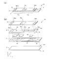
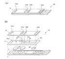
- FIG. 1A and 1B are a perspective view and an exploded perspective view of a biosensor 101 of the present embodiment.
- the biosensor 101 includes a base substrate 2, an electrode layer 4, first and second reagent layers 6 ⁇ / b> A and 6 ⁇ / b> B, a spacer substrate 8, and a top cover substrate 10.
- the base substrate 2, the spacer substrate 8, and the top cover substrate 10 have, for example, a longitudinal direction along the x direction, and are more in the x direction than the length in the y direction that is the width direction. It has a strip shape with a large length.
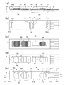
- 2A and 2B are a cross-sectional view and a plan view of the biosensor 101, respectively.
- 2C, 2D, and 2E are a plan view with the top cover substrate 10 removed, a plan view with the top cover substrate 10 and the first and second reagent layers 6A and 6B removed, and a spacer substrate, respectively. It is the top view which removed the structure above 8.
- the structure of the biosensor 101 will be described in detail with reference to these drawings.
- the base substrate 2 supports the entire structure of the biosensor 101.
- the base substrate 2 has a main surface 2m and a main surface 2r, and has a strip shape as described above.
- the main surface of the substrate means a main wide surface that supports a structure as a substrate.
- the electrode layer 4 is located on the main surface 2 m of the base substrate 2.
- the electrode layer 4 includes at least a first electrode pair 4a and a second electrode pair 4b.
- the first electrode pair 4a and the second electrode pair 4b are used to detect the first substance and the second substance, which are different substances in the subject.
- the first substance is HbA1c
- the second substance is Hb.
- the first electrode pair 4a includes a working electrode 4aw and a counter electrode 4ac.
- the first electrode pair 4a includes two working electrodes 4aw and three counter electrodes 4ac.
- the two working electrodes 4aw are connected to the terminal 4ed by the wiring part 4dd.
- the three counter electrodes 4ac are connected to the terminal 4ea by the wiring part 4da.
- the working electrode 4aw and the counter electrode 4ac are alternately arranged.
- the second electrode pair 4b includes a working electrode 4bw and a counter electrode 4bc.
- the second electrode pair 4b includes one working electrode 4bw and two counter electrodes 4bc.
- the working electrode 4bw is connected to the terminal 4ec by the wiring portion 4dc.
- the two counter electrodes 4bc are connected to the terminal 4eb by the wiring part 4db.
- the working electrode 4bw and the counter electrode 4bc are alternately arranged.
- a pair of counter electrodes 4ac sandwiching each working electrode 4aw is provided with a circular cut ca.
- a pair of counter electrodes 4bc sandwiching the working electrode 4bw is also provided with a circular cut cb.
- the above-described electrode structure in the electrode layer 4 is configured by patterning a metal film that continuously covers substantially the entire main surface 2 m of the base substrate 2.
- the spacer substrate 8 is disposed on the electrode layer 4 and includes a first opening 8a and a second opening 8b.
- the length of the spacer substrate 8 in the longitudinal direction is smaller than the length of the base substrate 2. Therefore, the terminals 4ea to 4ed of the electrode layer 4 are not covered with the spacer substrate 8, but are exposed.
- the first opening 8 a and the second opening 8 b are through holes that reach the two main surfaces 8 m and 8 r of the spacer substrate 8. Further, the first opening 8a and the second opening 8b are independent spaces and do not communicate with each other.
- the spacer substrate 8 is sandwiched between the base substrate 2 and the top cover substrate 10, the first opening 8a and the second opening 8b hold the specimen, and the specimen is connected to the first and second reagent layers 6A and 6B. It becomes a reaction chamber for detecting an electrical change of the subject caused by the reaction.
- Each of the first opening 8 a and the second opening 8 b has a rectangular shape having a length along the longitudinal direction of the spacer substrate 8, and is arranged along the longitudinal direction of the spacer substrate 8. Therefore, in the vicinity of the center of the spacer substrate 8, one end 8ac of the first opening 8a is close to one end 8bc of the second opening 8b. The other end 8ae of the first opening 8a and the other end 8be of the second opening 8b are close to both ends in the longitudinal direction of the spacer substrate 8, respectively.
- the first substance in the subject held in the first opening 8a is detected with high sensitivity. That is, the volume of the reaction chamber for detecting the first substance is larger than the volume of the reaction chamber for detecting the second substance. For this reason, it is preferable that the area of the first opening 8a is larger than the area of the second opening 8b.
- the lengths of the first opening 8a and the second opening 8b in the x direction are La and Lb, and the y direction (direction perpendicular to the longitudinal direction).
- Wa and Wb are La, L> Lb and Wa> Wb.
- the size of the first opening 8a and the second opening 8b can be determined according to the concentration of the first substance and the second substance in the subject, the required amount of the subject taking into account the detection sensitivity in the detection method used.
- the spacer substrate 8 has a thickness (z direction) at which the capillary force can act on the subject. )have.
- the spacer substrate 8 is disposed on the electrode layer 4, a part of the first electrode pair 4a and a part of the second electrode pair 4b are exposed in the first opening 8a and the second opening 8b, respectively.
- the electrical or electrochemical change of the subject held in the first opening 8a and the second opening 8b can be detected by the first electrode pair 4a and the second electrode pair 4b.
- the first opening 8a the sum of the lengths of the boundaries between the working electrode 4aw and the counter electrode 4ac of the first electrode pair 4a is 4 ⁇ Wa, and in the second opening 8b, the working electrode 4bw of the second electrode pair 4b.
- the total length of the boundary between the counter electrode 4bc and 2 ⁇ Wb That is, the total length of the boundary between the working electrode and the counter electrode is longer in the first electrode pair 4a than in the second electrode pair 4b, and the detection sensitivity of the first electrode pair 4a is enhanced.
- the first reagent layer 6A and the second reagent layer 6B include a first reagent and a second reagent, respectively.
- the first reagent and the second reagent react with the first substance and the second substance of the specimen, or the substances derived from the first substance and the second substance generated by the pretreatment, respectively, and are electrically detected by the specimen.
- the first reagent is fructosyl peptidase, which is a detection enzyme that specifically reacts with fructosylvalylhistidine generated by pretreating Hb1Ac, and is immobilized on the first reagent layer.
- the second reagent is potassium ferricyanide that is a mediator that reacts with all Hb including Hb1Ac, and is immobilized on the second reagent layer.
- the first reagent layer 6A and the second reagent layer 6B are disposed in the first opening 8a and the second opening 8b of the spacer substrate 8, respectively. More specifically, the first reagent layer 6A is located near the boundary between the working electrode 4aw and the counter electrode 4ac of the two first electrode pairs 4a, and the second reagent layer 6B is an action of the second electrode pair 4b. It is located on the vicinity of the boundary between the pole 4bw and the counter electrode 4bc. In the present embodiment, when the materials of the first reagent layer 6A and the second reagent layer 6B are dropped from above the electrode layer 4, the regions where the material spreads are defined by the circular cuts ca and cb provided in the counter electrode. Is done.
- the amount of the first reagent layer 6A and the second reagent layer 6B located in the vicinity between the working electrode and the counter electrode is constant, and variation in current during detection of the first substance and the second substance between the biosensors. Can be suppressed.
- the top cover substrate 10 is located on the spacer substrate 8.
- the top cover substrate 10 has an introduction portion including at least one introduction opening. In this embodiment, it has one introduction opening 10c.
- the introduction opening 10c overlaps a part of the first opening 8a and a part of the second opening 8b. More specifically, one end 8ac in the longitudinal direction of the first opening 8a and one end 8bc in the longitudinal direction of the second opening 8b are located in the introduction opening 10c. Therefore, the introduction opening 10c communicates with the first opening 8a and the second opening 8b, and when the subject is dropped onto the introduction opening 10c, the subject flows to the first opening 8a and the second opening 8b. .
- the top cover substrate 10 further includes a first discharge port 10ea and a second discharge port 10eb.
- the first outlet 10ea and the second outlet 10eb overlap a part of the first opening 8a and a part of the second opening 8b, and the other end 8ae of the first opening 8a and the other end 8be of the second opening 8b.
- the subject to the first opening 8a and the second opening 8b by capillary force.
- the first discharge port 10ea and the second discharge port 10eb may not be provided.
- the subject introduced from the introduction opening 10c flows into the first opening 8a and the second opening 8b according to gravity.
- the first substance that includes the introduction opening 10c, the first opening 8a, and the first discharge port 10ea is detected.
- the first cell 11a and the second cell 11b that includes the introduction opening 10c, the second opening 8b, and the second discharge port 10eb and detects the second substance are configured.
- the base substrate 2, the spacer substrate 8, and the top cover substrate 10 are made of an insulating material.
- various resin materials such as PET (polyethylene terephthalate) resin can be used.
- the electrode layer 4 is made of a conductive material. For example, it is formed by patterning a metal film such as palladium with a laser beam or the like.
- the base substrate 2, the electrode layer 4, the spacer substrate 8, and the top cover substrate 10 are bonded together by an adhesive, for example.
- FIG. 3 shows a configuration example of a measuring apparatus 201 that is loaded with the biosensor 101 and measures the first substance and the second substance of the subject.
- the measurement apparatus 201 includes a sensor mounting unit 16, a first measurement unit 17, a second measurement unit 18, and a control unit 19.
- the sensor mounting unit 16 includes connectors 16a to 16d that are in contact with the terminals 4ea to 4ed of the biosensor 101 and are electrically connected to the first measurement unit 17 and the second measurement unit 18.
- the first measurement unit 17 and the second measurement unit 18 apply predetermined voltages to the first electrode pair 4a and the second electrode pair 4b via the connectors 16a to 16d and the terminals 4ea to 4ed, respectively, and measure current values. To do.
- the measured current value is output to the control unit 19.
- the control unit 19 determines the concentrations of the first substance and the second substance from the current values (or voltage values) received from the first measurement unit 17 and the second measurement unit 18. For example, the control unit 19 stores a table in which the current value and the concentration value are related, or a function of the current value and the concentration value, and the concentrations of the first substance and the second substance based on the table or the function. Is calculated.
- the first substance is HbA1c and the second substance is Hb
- the ratio of HbA1c to Hb is calculated from the current value or concentration value to determine the HbA1c value.
- the measuring apparatus 201 further includes an operation unit 20, a timer 21, a storage unit 22, a temperature sensor 23, and a display unit 24, and the HbA1c value may be corrected with reference to information from the temperature sensor 23.
- the corrected HbA1c value is stored in the storage unit 22 together with information related to the time from the timer 21 and displayed on the display unit 24.
- the control unit 19 performs processing such as measurement, display, and measurement result storage based on a command input by the operator from the operation unit 20.
- the control unit 19 of the measuring apparatus 201 includes an arithmetic device such as a microcomputer and a storage unit.
- the storage unit stores a program that defines the measurement procedure, and the arithmetic device executes the program to measure the concentrations of the first substance and the second substance.
- the first measuring unit 17 and the second measuring unit 18 include a power supply circuit that generates a predetermined voltage and an ammeter that measures a current value. The measured current value is converted into a digital signal, for example, and the above-described processing is performed by the control unit 19.
- the display unit 24 may be a liquid crystal display device, an organic EL display device, or the like.
- Pretreatment of subject pretreatment of a blood sample collected from a subject is performed. Specifically, a hemolytic agent such as a surfactant is added to the collected blood sample, and Hb in erythrocytes of the blood sample is eluted.
- a hemolytic agent such as a surfactant
- protease which is a degrading enzyme
- HbA1c in Hb produces fructosyl valyl histidine.
- the pretreated blood sample is simply referred to as a subject.
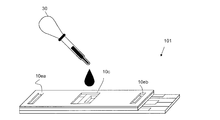
- the biosensor 101 is attached to the measuring apparatus 201.
- the subject is sucked by the dropper 30 and dropped onto the vicinity of the introduction opening 10c of the biosensor 101 as shown in FIG.
- the subject spotted in the vicinity of the introduction opening 10c is drawn from the introduction opening 10c by capillary force and is introduced into the first opening 8a and the second opening 8b simultaneously, that is, in parallel.
- fructosyl valyl histidine in the subject introduced into the first opening 8a reacts with fructosyl peptidase, which is the first reagent in the first reagent layer 6A, to generate hydrogen peroxide.
- fructosyl peptidase which is the first reagent in the first reagent layer 6A
- the conductivity of the specimen changes.
- the value of the current flowing between the working electrode 4aw and the counter electrode 4ac of the first electrode pair 4a also changes according to the amount of generated hydrogen peroxide. Since fructosyl valyl histidine is derived from HbA1c, the current value changes according to the amount of HbA1c in the subject.
- a current value corresponding to the amount of Hb can be detected.
- the measuring device 201 applies a voltage of 0.1V to 0.4V between the working electrode 4aw and the counter electrode 4ac of the first electrode pair 4a for 5 to 10 seconds, thereby working electrode. The amount of current flowing between 4aw and the counter electrode 4ac is measured. Similarly, a voltage of 0.1 V to 0.4 V is applied between the working electrode 4bw and the counter electrode 4bc of the second electrode pair 4b for 5 to 10 seconds, and flows between the working electrode 4bw and the counter electrode 4bc. Measure the amount of current.
- the current values measured by the first measuring unit 17 and the second measuring unit 18 correspond to the amount of HbA1c and the amount of Hb.
- the measuring apparatus 201 obtains the HbA1c value using these current values.
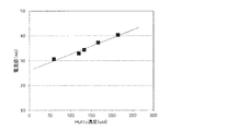
- FIG. 5 and FIG. 6 show the results of measurement using a subject whose HbA1c and Hb concentrations are known.
- the current value was measured by the first measurement unit 17 using five types of specimens whose HbA1c concentrations were known in advance.
- FIG. 5 shows a graph in which the HbA1c concentration of the subject is plotted on the horizontal axis and the measured current value is plotted on the vertical axis.
- the current value was measured by the second measurement unit 18 using five types of specimens whose Hb concentrations were known in advance.
- FIG. 6 shows a graph in which the Hb concentration of the subject is plotted on the horizontal axis and the measured current value is plotted on the vertical axis.
- the HbA1c concentration and the current value, and the Hb concentration and the current value show a linear relationship. From this, it can be seen that the HbA1c concentration and the Hb concentration are electrochemically measured using the biosensor 101 of the present disclosure, and the HbA1c value can be obtained with high accuracy.
- the electrode is provided without providing a branched flow path that guides the analyte to the reaction chamber.
- the subject can be introduced into the first opening and the second opening provided with. That is, the biosensor does not have a branched flow path. For this reason, by increasing the area of the first opening and / or the second opening, it is possible to increase the amount of the subject used for the measurement and to increase the length of the boundary between the working electrode and the counter electrode. The detection sensitivity of the biosensor can be increased.
- the subject can be introduced simultaneously with the first opening and the second opening provided in the spacer substrate by introducing the subject from the introduction portion, the first opening and the second opening can be introduced. It is possible to shorten the time until the sample is filled and the measurement is started.
- the subject by reacting the subject with the first substance and the second substance in the first opening and the second opening, respectively, two kinds of kinds in the subject are obtained using the first electrode pair and the second electrode pair. Substances can be detected or quantified. Since the first opening and the second opening are independent, the measurement of one of the first substance and the second substance does not affect the measurement of the other, and two kinds of substances are independently and highly accurately It can be detected.
- the first opening and the second opening are independent, each size can be arbitrarily set, and the amount of the subject to be used can be adjusted independently. For this reason, the amount of the analyte to be used can be changed according to the concentration and detection sensitivity of the substance to be detected in the analyte, and measurement can be performed with appropriate sensitivity. For example, by making the area of the first opening larger than the area of the second opening, the detection accuracy of the substance to be detected using the first substance can be increased. Further, by increasing the area of the first opening, the length of the boundary between the working electrode and the counter electrode in the first electrode pair can be increased, and the detection sensitivity can be further increased. Since the first opening and the second opening are independent, when the subject is introduced into the first opening and the second opening using the capillary force, the capillary force acting on each of them can be adjusted independently.
- the introduction part is provided on the top cover substrate, it is possible to fill the first opening and the second opening with the subject in a short time by increasing the dropping amount of the subject, and shorten the measurement time. it can. Further, even if the areas of the first electrode pair and the second electrode pair for detection are increased, a sufficient amount of the subject can be brought into contact with the electrode pair in a short time. For this reason, detection sensitivity can be raised.
- the subject can be introduced into the first opening and the second opening using capillary force. For this reason, the first opening and the second opening can be filled with the subject stably and reliably.
- FIGS. 7A and 7B are a perspective view and an exploded perspective view of the biosensor 101 of the present embodiment.
- the biosensor 102 differs from the biosensor 101 of the first embodiment in that the top cover substrate 10 includes an introduction portion including a first introduction opening 10ca and a second introduction opening 10cb.
- One end 8ac of the first opening 8a is located in the first introduction opening 10ca, and one end 8bc of the second opening 8b is located in the second introduction opening 10cb.
- the first introduction opening 10ca and the second introduction opening 10cb are independent from each other and do not communicate with each other. For this reason, it is possible to adjust each area (size) independently.
- the magnitude of the capillary force acting on the first opening 8a and the second opening 8b can be adjusted independently by changing the areas of the first introduction opening 10ca and the second introduction opening 10cb that overlap with each of them. Can do. Therefore, even if the areas or shapes of the first opening 8a and the second opening 8b are different, it is possible to adjust so that an appropriate capillary force acts on each of them, and the subject is more reliably placed in the biosensor 102. It is possible to introduce.
- the first introduction opening 10ca and the second introduction opening 10cb are close to each other. Therefore, for example, if the subject is dropped between the first introduction opening 10ca and the second introduction opening 10cb, the subject can be introduced into both the first introduction opening 10ca and the second introduction opening 10cb. It is possible to introduce the subject into the first opening 8a and the second opening 8b substantially simultaneously.
- FIG. 8 is an exploded perspective view of the biosensor 103 of the present embodiment.
- the biosensor 103 is different from the biosensor 101 of the first embodiment in that the first discharge port 8ad and the second discharge port 8bd are provided in the spacer substrate 8.
- the first discharge port 8ad is provided at the other end 8ae of the first opening 8a and has an opening on the side surface in the longitudinal direction of the spacer substrate 8.
- the second discharge port 8bd is provided at the other end 8be of the second opening 8b, and has an opening on the other side surface of the spacer substrate 8 in the longitudinal direction.
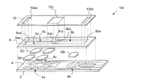
- FIG. 9 is an exploded perspective view of the biosensor 104 of the present embodiment.
- the biosensor 104 includes a first opening 8a, a second opening 8b, and a third opening 8c provided in the spacer substrate 8, a point that the electrode layer 4 further includes a third electrode pair 4c, and a third reagent. It differs from the biosensor 101 of the first embodiment in that the layer 6C is provided.
- the first opening 8a and the third opening 8c are arranged in a direction perpendicular to the longitudinal direction. Further, one end 8ac of the first opening 8a and one end 8cc of the third opening 8c are close to one end 8bc of the second opening 8b.
- the introduction opening 10c overlaps one end 8ac of the first opening 8a, one end 8cc of the third opening 8c, and one end 8bc of the second opening 8b.
- the first outlet 10ea overlaps the other end 8ae of the first opening 8a and the one end 8ce of the third opening 8c.
- a part of the third electrode pair 4c is exposed in the third opening 8c.
- the third reagent layer 6C is located in the third opening 8c.
- the subject is introduced in parallel with the first opening 8a, the second opening 8b, and the third opening 8c provided in the spacer substrate 8 by introducing the subject from the introduction portion of the top cover substrate 10.
- a substance that reacts with the third substance in the subject or a substance derived from the third substance in the third reagent layer 6C it is possible to detect three substances in the subject.
- the first to fourth embodiments can be implemented in combination as appropriate.
- the number of openings provided independently in the spacer substrate 8 is not limited to 2 or 3, but may be 4 or more.
- the subject is not limited to blood or a liquid pretreated with blood, and the first substance and the second substance are not limited to Hb1Ac and Hb, and a biosensor that detects various substances can be realized.
- the biosensor of the present disclosure can be suitably used for a biosensor used in the medical / clinical testing field, the pharmaceutical field, or various industrial fields.
Abstract
This biosensor is provided with: a base substrate 2 having a main surface; an electrode layer 4 disposed on the main surface of the base substrate 2 and including a first electrode pair 4a and a second electrode pair 4b each of which has a working electrode and a counter electrode; a spacer substrate 8 disposed on the electrode layer and having a first opening 8a from which a part of the first electrode pair is exposed and a second opening 8b which is independent of the first opening and from which a part of the second electrode pair is exposed; a first reagent layer 6A disposed in the first opening and containing a first reagent which reacts with a specimen; a second reagent layer 6B disposed in the second opening and containing a second reagent which reacts with the specimen; and a top cover substrate 10 that has an introduction section 10c including at least one introduction opening and that is disposed on the spacer substrate, the introduction section overlapping with a part of the first opening and a part of the second opening in the spacer substrate.
Description
本願は、被検体に含まれる特定物質の濃度を計測するバイオセンサに関する。
This application relates to a biosensor that measures the concentration of a specific substance contained in a subject.
医療・臨床検査分野、製薬分野をはじめとして種々の分野でバイオセンサが実用化されている。たとえば、血液中の種々の物質の濃度を測定するバイオセンサが実用化され、医療および臨床検査分野において広く利用されている。
Biosensors have been put into practical use in various fields including medical / clinical testing and pharmaceutical fields. For example, biosensors that measure the concentration of various substances in blood have been put into practical use and are widely used in the medical and clinical laboratory fields.
特許文献1は、血液凝固測定などの電気化学的血液テストストリップとして使用可能なマイクロ流体センサを開示している。このマイクロ流体センサは、毛管作用によって被測定流体が流れる分岐を有する流路と、分岐した2つの流路の末端に位置する反応ゾーンに設けられた電極対とを有する。特許文献1によれば、血液凝固の測定では凝固時間が重要であり、精度よくかつ再現性よく測定を行うために反応ゾーンにおける流体の流れを妨げる因子を最小にすることが重要であると開示している。
Patent Document 1 discloses a microfluidic sensor that can be used as an electrochemical blood test strip for blood coagulation measurement and the like. This microfluidic sensor has a flow path having a branch through which a fluid to be measured flows by capillary action, and an electrode pair provided in a reaction zone located at the end of the two branched flow paths. According to Patent Document 1, it is disclosed that coagulation time is important in blood coagulation measurement, and it is important to minimize factors that hinder fluid flow in the reaction zone in order to perform measurement with high accuracy and reproducibility. is doing.
バイオセンサの構造は、検出すべき物質の特性や検出に用いる測定方法に応じて最適化されていることが好ましい。本開示は、2種以上の物質をより精度よく測定することが可能な電気化学的測定法を用いたバイオセンサを提供する。
The structure of the biosensor is preferably optimized according to the characteristics of the substance to be detected and the measurement method used for detection. The present disclosure provides a biosensor using an electrochemical measurement method capable of more accurately measuring two or more substances.
本開示のバイオセンサは、主面を有するベース基板と、前記ベース基板の前記主面上に位置し、それぞれ作用極および対極を有する第1電極対および第2電極対を含む電極層と、前記電極層上に配置され、前記第1電極対の一部を露出する第1開口および前記第1開口と独立しており、前記第2電極対の一部を露出する第2開口とを有するスペーサ基板と、被検体と反応する第1試薬を含み、前記第1開口内に位置する第1試薬層と、前記被検体と反応する第2試薬を含み、前記第2開口内に位置する第2試薬層と、少なくとも1つの導入開口を含む導入部を有し、前記スペーサ基板上に配置されたトップカバー基板であって、前記導入部が、前記スペーサ基板の前記第1開口の一部および前記第2開口の一部と重なっているトップカバー基板とを備える。
The biosensor of the present disclosure includes a base substrate having a main surface, an electrode layer that is located on the main surface of the base substrate and includes a first electrode pair and a second electrode pair each having a working electrode and a counter electrode, A spacer disposed on the electrode layer and having a first opening that exposes a part of the first electrode pair and a second opening that is independent of the first opening and exposes a part of the second electrode pair A second reagent that includes a substrate, a first reagent that reacts with the analyte, and that is located within the first opening; and a second reagent that reacts with the analyte and is located within the second opening. A top cover substrate disposed on the spacer substrate, wherein the introduction portion includes a part of the first opening of the spacer substrate and the reagent layer; and an introduction portion including at least one introduction opening. Top cover that overlaps part of the second opening And a plate.
本開示のバイオセンサによれば、トップカバー基板の導入開口が第1開口および第2開口と重なっているため、被検体を反応室に導く分岐付きの流路を設けることなく、電極が設けられた第1開口および第2開口内に被検体を導入することができる。このため、第1開口および/または第2開口の面積を大きくすることによって、測定に用いる被検体の量を増加させ、また、作用極と対極との境界の長さを増加させることが可能となり、バイオセンサの検出感度を高めることが可能となる。よって、電気化学的測定法により2種以上の物質を精度よく測定することが可能である。
According to the biosensor of the present disclosure, since the introduction opening of the top cover substrate overlaps with the first opening and the second opening, the electrode is provided without providing a branched flow path for guiding the analyte to the reaction chamber. The subject can be introduced into the first opening and the second opening. Therefore, by increasing the area of the first opening and / or the second opening, it is possible to increase the amount of the subject used for the measurement and to increase the length of the boundary between the working electrode and the counter electrode. The detection sensitivity of the biosensor can be increased. Therefore, it is possible to accurately measure two or more substances by an electrochemical measurement method.
本願発明者は、電気化学的測定法により2種以上の物質を精度よく測定することができるバイオセンサの構造を詳細に検討した。たとえば、バイオセンサによって、ヘモグロビンA1c(以下、HbA1cと記載する。)値を電気化学的に測定する場合を考える。HbA1c値は、赤血球中のヘモグロビン(Hbと記載する。)のうち、糖と結合しているヘモグロビン(HbA1c)の割合で示される検査値である。HbA1c値は、過去1~2ヶ月の平均的な血糖値を反映するため、血中のグルコース値と比較すると、検査前の食事による影響を受けにくく、糖尿病を管理するより正確な指標として用いることが可能である。HbA1c値を求めるためには、HbA1cの濃度(量)とHbの濃度(量)とを求める必要がある。ここで、Hbは、HbA1cおよびその他の誘導体を含む総Hbを意味する。しかし、HbA1cの濃度は一般的に低いため、特に電気化学的にHbA1cの濃度を測定することは難しい。このため、主としてHbA1c値は光学的分光方法を用いて測定されていた。
The inventor of the present application has examined in detail the structure of a biosensor that can accurately measure two or more substances by an electrochemical measurement method. For example, consider a case where the hemoglobin A1c (hereinafter referred to as HbA1c) value is electrochemically measured by a biosensor. The HbA1c value is a test value indicated by the proportion of hemoglobin (HbA1c) bound to sugar in hemoglobin (denoted as Hb) in erythrocytes. The HbA1c value reflects the average blood glucose level in the past 1 to 2 months, so it is less affected by the diet before the test and should be used as a more accurate indicator for managing diabetes. Is possible. In order to obtain the HbA1c value, it is necessary to obtain the concentration (amount) of HbA1c and the concentration (amount) of Hb. Here, Hb means total Hb including HbA1c and other derivatives. However, since the concentration of HbA1c is generally low, it is particularly difficult to electrochemically measure the concentration of HbA1c. For this reason, the HbA1c value was mainly measured using an optical spectroscopic method.
電気化学的測定法を用いるバイオセンサにおいて、測定すべき物質の濃度が低い場合、できるだけ多くの量の被検体を用い、かつ、電極における検出領域を大きくし、検出精度を高めることが考えられる。従来の2種以上物質を検出するバイオセンサでは、分岐を有するマイクロ流路を用いて被検体を2以上に分割し、それぞれの反応室で電気化学反応を利用して被検体中の物質を検出していた。しかし、このような構造のバイオセンサでは、分岐を有するマイクロ流路を形成するため、電極を大きく形成できない場合がある。本願発明者はこのような課題に鑑み、新規な構造を備えたバイオセンサを想到した。本開示のバイオセンサの概要は以下のとおりである。
In a biosensor using an electrochemical measurement method, when the concentration of a substance to be measured is low, it is conceivable to increase the detection accuracy by using as much sample as possible and increasing the detection area of the electrode. In conventional biosensors that detect two or more substances, the analyte is divided into two or more using a microchannel having a branch, and the substances in the analyte are detected using an electrochemical reaction in each reaction chamber. Was. However, in the biosensor having such a structure, since the microchannel having a branch is formed, there is a case where a large electrode cannot be formed. In view of such a problem, the inventor of the present application has come up with a biosensor having a novel structure. The outline of the biosensor of the present disclosure is as follows.
[項目1]
主面を有するベース基板と、
前記ベース基板の前記主面上に位置し、それぞれ作用極および対極を有する第1電極対および第2電極対を含む電極層と、
前記電極層上に配置され、前記第1電極対の一部を露出する第1開口および前記第1開口と独立しており、前記第2電極対の一部を露出する第2開口を有するスペーサ基板と、
被検体と反応する第1試薬を含み、前記第1開口内に位置する第1試薬層と、
前記被検体と反応する第2試薬を含み、前記第2開口内に位置する第2試薬層と、
少なくとも1つの導入開口を含む導入部を有し、前記スペーサ基板上に配置されたトップカバー基板であって、前記導入部が、前記スペーサ基板の前記第1開口の一部および前記第2開口の一部と重なっているトップカバー基板と、
を備えたバイオセンサ。 [Item 1]
A base substrate having a main surface;
An electrode layer located on the main surface of the base substrate and including a first electrode pair and a second electrode pair each having a working electrode and a counter electrode;
A spacer disposed on the electrode layer and having a first opening exposing a part of the first electrode pair and a second opening exposing a part of the second electrode pair, independent of the first opening. A substrate,
A first reagent layer that includes a first reagent that reacts with the analyte and is located within the first opening;
A second reagent layer that includes a second reagent that reacts with the analyte and is located within the second opening;
A top cover substrate disposed on the spacer substrate, the introduction portion including a part of the first opening and the second opening of the spacer substrate. A top cover substrate overlapping with a part,
Biosensor equipped with.
この構成によれば、トップカバー基板の導入開口が第1開口および第2開口と重なっているため、被検体を反応室に導く分岐付きの流路を設けることなく、電極が設けられた第1開口および第2開口内に被検体を導入することができる。このため、第1開口および/または第2開口の面積を大きくすることによって、測定に用いる被検体の量を増加させ、また、作用極と対極との境界の長さを増加させることが可能となり、バイオセンサの検出感度を高めることが可能となる。また、導入部から被検体を導入することにより、スペーサ基板に設けられた第1開口および第2開口に並行して同時に被検体を導入することができるため、第1開口および第2開口を被検体で満たし、測定を開示するまでの時間を短縮することが可能となる。また、第1開口および第2開口が独立しているため、それぞれの大きさを任意に設定でき、使用する被検体の量を独立して調整できる。このため、被検体中の検出すべき物質の濃度、検出感度に応じて、使用する被検体の量を変化させることができ、適切な感度で測定を行うことができる。
According to this configuration, since the introduction opening of the top cover substrate overlaps with the first opening and the second opening, the first electrode provided with the electrodes is provided without providing a branched flow path for guiding the analyte to the reaction chamber. A subject can be introduced into the opening and the second opening. Therefore, by increasing the area of the first opening and / or the second opening, it is possible to increase the amount of the subject used for the measurement and to increase the length of the boundary between the working electrode and the counter electrode. The detection sensitivity of the biosensor can be increased. In addition, since the subject can be introduced simultaneously with the first opening and the second opening provided in the spacer substrate by introducing the subject from the introduction portion, the first opening and the second opening can be introduced. It is possible to shorten the time until the sample is filled and the measurement is disclosed. Further, since the first opening and the second opening are independent, the size of each can be arbitrarily set, and the amount of the subject to be used can be adjusted independently. For this reason, the amount of the analyte to be used can be changed according to the concentration and detection sensitivity of the substance to be detected in the analyte, and measurement can be performed with appropriate sensitivity.
また、トップカバー基板に導入部を設けるため、被検体の滴下量を多くして、短時間で第1開口および第2開口を被検体で満たすことが可能であり、測定時間を短縮することができる。また、検出のための第1電極対および第2電極対の面積を大きくしても、短時間で、かつ、十分な量の被検体を電極対に接触させることができる。このため、検出感度を高めることができる。
In addition, since the introduction part is provided on the top cover substrate, it is possible to fill the first opening and the second opening with the subject in a short time by increasing the dropping amount of the subject, and shorten the measurement time. it can. Further, even if the areas of the first electrode pair and the second electrode pair for detection are increased, a sufficient amount of the subject can be brought into contact with the electrode pair in a short time. For this reason, detection sensitivity can be raised.
[項目2]
前記スペーサ基板において、前記第1開口の面積は前記第2開口よりも大きい項目1に記載のバイオセンサ。 [Item 2]
The biosensor according to item 1, wherein the spacer substrate has an area of the first opening larger than that of the second opening.
前記スペーサ基板において、前記第1開口の面積は前記第2開口よりも大きい項目1に記載のバイオセンサ。 [Item 2]
The biosensor according to item 1, wherein the spacer substrate has an area of the first opening larger than that of the second opening.
この構成によれば、第1開口が大きいため、より多くの被検体を用いて測定を行うことができ、第1物質を用いて検出すべき物質の検出精度を高めることができる。
According to this configuration, since the first opening is large, the measurement can be performed using a larger number of subjects, and the detection accuracy of the substance to be detected using the first substance can be increased.
[項目3]
前記電極層において、前記第1開口内で露出している第1電極対の前記作用極と隣接する前記対極との境界の長さは、前記第2開口内で露出している第2電極対の前記作用極と隣接する前記対極との境界の長さよりも大きい、項目1または2に記載のバイオセンサ。 [Item 3]
In the electrode layer, the length of the boundary between the working electrode of the first electrode pair exposed in the first opening and the adjacent counter electrode is the second electrode pair exposed in the second opening. The biosensor according toitem 1 or 2, wherein the biosensor is longer than a boundary length between the working electrode and the counter electrode adjacent thereto.
前記電極層において、前記第1開口内で露出している第1電極対の前記作用極と隣接する前記対極との境界の長さは、前記第2開口内で露出している第2電極対の前記作用極と隣接する前記対極との境界の長さよりも大きい、項目1または2に記載のバイオセンサ。 [Item 3]
In the electrode layer, the length of the boundary between the working electrode of the first electrode pair exposed in the first opening and the adjacent counter electrode is the second electrode pair exposed in the second opening. The biosensor according to
この構成によれば、第1電極対における作用極と対極との境界の長さを大きくできるため、検出感度を高めることができる。
According to this configuration, since the length of the boundary between the working electrode and the counter electrode in the first electrode pair can be increased, the detection sensitivity can be increased.
[項目4]
前記スペーサ基板の前記第1開口および前記第2開口とそれぞれ連通している第1排出口および第2排出口を有する項目1に記載のバイオセンサ。 [Item 4]
The biosensor according to item 1, comprising a first discharge port and a second discharge port communicating with the first opening and the second opening of the spacer substrate, respectively.
前記スペーサ基板の前記第1開口および前記第2開口とそれぞれ連通している第1排出口および第2排出口を有する項目1に記載のバイオセンサ。 [Item 4]
The biosensor according to item 1, comprising a first discharge port and a second discharge port communicating with the first opening and the second opening of the spacer substrate, respectively.
この構成によれば、第1排出口および第2排出口を備えているため、毛細管力によって被検体を第1開口および第2開口内に確実に導入することができる。
According to this configuration, since the first discharge port and the second discharge port are provided, the subject can be reliably introduced into the first opening and the second opening by capillary force.
[項目5]
前記第1排出口および第2排出口は、前記スペーサ基板に位置しており、前記スペーサ基板の側面に開口を有し、それぞれ前記第1開口および前記第2開口に接続されている、項目4に記載のバイオセンサ。 [Item 5]
The first discharge port and the second discharge port are located in the spacer substrate, have an opening on a side surface of the spacer substrate, and are connected to the first opening and the second opening, respectively. The biosensor described in 1.
この構成によれば、トップカバー基板の主面には、導入開口しか位置していないため、第1排出口および第2排出口から何らかの異物が混入したり、操作者が第1排出口および第2排出口を導入開口と間違えて被検体を導入する可能性を低減することができる。
According to this configuration, since only the introduction opening is located on the main surface of the top cover substrate, some foreign matter is mixed in from the first discharge port and the second discharge port, or the operator can connect the first discharge port and the first discharge port. It is possible to reduce the possibility of introducing the subject by mistakenly introducing the two outlets with the introduction opening.
[項目6]
前記第1排出口および第2排出口は、前記トップカバー基板に位置しており、前記スペーサ基板の前記第1開口の他の一部および前記第2開口の他の一部と重なっている項目4に記載のバイオセンサ。 [Item 6]
The first discharge port and the second discharge port are located on the top cover substrate and overlap with another part of the first opening and the other part of the second opening of the spacer substrate. 4. The biosensor according to 4.
[項目7]
前記トップカバー基板において、前記導入部の前記導入開口は1つであり、前記導入開口が、前記スペーサ基板の前記第1開口の一部および前記第2開口の一部と重なっている、項目1から6のいずれかに記載のバイオセンサ。 [Item 7]
In the top cover substrate, the introduction portion has one introduction opening, and the introduction opening overlaps a part of the first opening and a part of the second opening of the spacer substrate. The biosensor according to any one of 6 to 6.
この構成によれば、1つの導入開口から第1開口および第2開口へ同時に被検体を導入することができるので、測定時の操作が簡略になる。
According to this configuration, since the subject can be introduced simultaneously from one introduction opening to the first opening and the second opening, the operation at the time of measurement is simplified.
[項目8]
前記トップカバー基板において、前記導入部の前記導入開口は2つであり、一方の導入開口は、前記スペーサ基板の前記第1開口の一部と重なっており、他方の導入開口は、前記第2開口の一部と重なっている、項目1から6のいずれかに記載のバイオセンサ。 [Item 8]
In the top cover substrate, the introduction portion has two introduction openings, one introduction opening overlaps a part of the first opening of the spacer substrate, and the other introduction opening is the second introduction opening. The biosensor according to any one of items 1 to 6, wherein the biosensor overlaps a part of the opening.
この構成によれば、前記スペーサ基板の前記第1開口および前記第2開口にそれぞれ導入開口が設けられるため、第1開口および第2開口の毛細管力をより独立して調整しやすくなる。よって、検出感度が異なるために、第1開口および第2開口に導入すべき被検体の量が大きく異なる場合でも、導入に要する時間を揃えたり、第1開口および第2開口の全体に被検体を確実に導入することが可能となり、測定時間の短縮や、再現性の高い測定を行うことが可能となる。
According to this configuration, since the introduction opening is provided in each of the first opening and the second opening of the spacer substrate, the capillary force of the first opening and the second opening can be easily adjusted independently. Therefore, even when the amount of the subject to be introduced into the first opening and the second opening is greatly different because the detection sensitivities are different, the time required for introduction is made uniform, or the subject is placed over the first opening and the second opening. Can be reliably introduced, and measurement time can be shortened and highly reproducible measurement can be performed.
[項目9]
前記ベース基板、前記スペーサ基板および前記トップカバー基板は、第1方向の長さが前記第1方向に直交する第2方向の長さよりも大きいストリップ形状を有し、
前記第1開口および前記第2開口は、前記スペーサ基板において、前記第1方向に隣接して配列されており、
前記トップカバー基板において、前記導入部の前記導入開口は1つであり、前記導入開口は、前記第1開口および前記第2開口の互いに隣接する部分と重なっている、項目1に記載のバイオセンサ。 [Item 9]
The base substrate, the spacer substrate, and the top cover substrate have a strip shape in which a length in a first direction is larger than a length in a second direction orthogonal to the first direction;
The first opening and the second opening are arranged adjacent to each other in the first direction in the spacer substrate,
The biosensor according to item 1, wherein, in the top cover substrate, the introduction portion has one introduction opening, and the introduction opening overlaps a portion of the first opening and the second opening that are adjacent to each other. .
[項目10]
前記トップカバー基板は、第1排出口および第2排出口をさらに有し、
前記第1排出口および前記導入部の前記導入開口は、前記スペーサ基板の前記第1開口の前記第1方向における両端とそれぞれ重なっており、
前記第2排出口および前記導入部の前記導入開口は、前記スペーサ基板の前記第2開口の前記第1方向における両端とそれぞれ重なっている、項目9に記載のバイオセンサ。 [Item 10]
The top cover substrate further has a first outlet and a second outlet,
The introduction openings of the first discharge port and the introduction portion respectively overlap with both ends in the first direction of the first opening of the spacer substrate,
10. The biosensor according to item 9, wherein the introduction opening of the second discharge port and the introduction part overlaps both ends of the second opening of the spacer substrate in the first direction, respectively.
[項目11]
前記被検体は、赤血球から分離されたヘモグロビンを含み、
前記ヘモグロビンはヘモグロビンA1cを含み、
前記第1試薬は、前記ヘモグロビンA1cまたは前記ヘモグロビンA1cに由来する物質と特異的に反応し、
前記第2試薬は前記ヘモグロビンと反応する、項目1から10のいずれかに記載のバイオセンサ。 [Item 11]
The subject includes hemoglobin separated from red blood cells,
The hemoglobin includes hemoglobin A1c,
The first reagent specifically reacts with the hemoglobin A1c or a substance derived from the hemoglobin A1c,
The biosensor according to any one of items 1 to 10, wherein the second reagent reacts with the hemoglobin.
以下、図面を参照しながら、本開示のバイオセンサの実施形態を詳細に説明する。本開示のバイオセンサは、被検体に含まれる2以上の異なる物質を、電気化学的に検出および/または定量することができる。本開示の実施形態では、被検体中に含まれる第1物質および第2物質を検出するバイオセンサの一形態を説明する。本開示のバイオセンサは特に被検体に含まれる2以上の物質の検出感度が異なる場合において、検出感度が相対的に低い物質でも、感度を高めて検出することが可能である。以下に示す実施形態では、第1物質および第2物質として血液に前処理を施した被検体中のHbA1cおよびHbの濃度を電気化学的に測定するバイオセンサを例に挙げて説明する。しかし、本開示のバイオセンサは、他の物質の検出にも好適に用いることが可能である。以下に示す実施形態は例示であって、本発明は実施形態により制限されない。また、以下の実施形態の説明において、分かり易さのため、あるいは不要な重複を避けるため、図面に参照符号を付し、同様の説明を省略する場合、あるいは、説明で参照しない構成要素に参照符号を付さない場合がある。
Hereinafter, embodiments of the biosensor of the present disclosure will be described in detail with reference to the drawings. The biosensor of the present disclosure can electrochemically detect and / or quantify two or more different substances contained in a subject. In the embodiment of the present disclosure, one mode of a biosensor that detects a first substance and a second substance contained in a subject will be described. The biosensor of the present disclosure can detect a substance having a relatively low detection sensitivity with an increased sensitivity, particularly when the detection sensitivities of two or more substances contained in the subject are different. In the embodiment described below, a biosensor that electrochemically measures the concentrations of HbA1c and Hb in a subject in which blood has been pretreated as the first substance and the second substance will be described as an example. However, the biosensor of the present disclosure can be suitably used for detecting other substances. The following embodiment is an exemplification, and the present invention is not limited by the embodiment. In the following description of the embodiments, for ease of understanding or to avoid unnecessary duplication, reference numerals are attached to the drawings, and the same description is omitted, or reference is made to components that are not referred to in the description. There are cases where no reference is given.
(第1の実施形態)
<バイオセンサの構造>
本開示のバイオセンサの第1の実施形態を説明する。図1(a)および(b)は、本実施形態のバイオセンサ101の斜視図および分解斜視図である。バイオセンサ101は、ベース基板2と、電極層4と、第1および第2試薬層6A、6Bと、スペーサ基板8と、トップカバー基板10とを備えている。図1(b)に示すように、ベース基板2、スペーサ基板8およびトップカバー基板10は、たとえば、x方向に沿って長手方向を有し、幅方向であるy方向の長さよりもx方向の長さが大きいストリップ形状を有している。 (First embodiment)
<Biosensor structure>
A first embodiment of the biosensor of the present disclosure will be described. 1A and 1B are a perspective view and an exploded perspective view of abiosensor 101 of the present embodiment. The biosensor 101 includes a base substrate 2, an electrode layer 4, first and second reagent layers 6 </ b> A and 6 </ b> B, a spacer substrate 8, and a top cover substrate 10. As shown in FIG. 1B, the base substrate 2, the spacer substrate 8, and the top cover substrate 10 have, for example, a longitudinal direction along the x direction, and are more in the x direction than the length in the y direction that is the width direction. It has a strip shape with a large length.
<バイオセンサの構造>
本開示のバイオセンサの第1の実施形態を説明する。図1(a)および(b)は、本実施形態のバイオセンサ101の斜視図および分解斜視図である。バイオセンサ101は、ベース基板2と、電極層4と、第1および第2試薬層6A、6Bと、スペーサ基板8と、トップカバー基板10とを備えている。図1(b)に示すように、ベース基板2、スペーサ基板8およびトップカバー基板10は、たとえば、x方向に沿って長手方向を有し、幅方向であるy方向の長さよりもx方向の長さが大きいストリップ形状を有している。 (First embodiment)
<Biosensor structure>
A first embodiment of the biosensor of the present disclosure will be described. 1A and 1B are a perspective view and an exploded perspective view of a
図2(a)および(b)は、バイオセンサ101の断面図および平面図である。図2(c)、(d)および(e)は、それぞれ、トップカバー基板10を取り除いた平面図、トップカバー基板10ならびに第1および第2試薬層6A、6Bを取り除いた平面図、スペーサ基板8より上の構造を取り除いた平面図である。これらの図を参照しながら、バイオセンサ101の構造を詳細に説明する。
2A and 2B are a cross-sectional view and a plan view of the biosensor 101, respectively. 2C, 2D, and 2E are a plan view with the top cover substrate 10 removed, a plan view with the top cover substrate 10 and the first and second reagent layers 6A and 6B removed, and a spacer substrate, respectively. It is the top view which removed the structure above 8. The structure of the biosensor 101 will be described in detail with reference to these drawings.
ベース基板2は、バイオセンサ101の全体の構造を支持する。ベース基板2は主面2mおよび主面2rを有し、上述したようにストリップ形状を備える。基板における主面とは、基板として構造物を支持する主要な広い面を意味する。
The base substrate 2 supports the entire structure of the biosensor 101. The base substrate 2 has a main surface 2m and a main surface 2r, and has a strip shape as described above. The main surface of the substrate means a main wide surface that supports a structure as a substrate.
電極層4はベース基板2の主面2mに位置している。電極層4は、少なくとも第1電極対4aおよび第2電極対4bを含んでいる。第1電極対4aおよび第2電極対4bは、被検体中の互いに異なる物質である第1物質および第2物質を検出するために用いられる。本実施形態では、第1物質はHbA1cであり、第2物質はHbである。
The electrode layer 4 is located on the main surface 2 m of the base substrate 2. The electrode layer 4 includes at least a first electrode pair 4a and a second electrode pair 4b. The first electrode pair 4a and the second electrode pair 4b are used to detect the first substance and the second substance, which are different substances in the subject. In the present embodiment, the first substance is HbA1c, and the second substance is Hb.
図2(e)に示すように、第1電極対4aは作用極4awおよび対極4acを含む。本実施形態では、第1電極対4aは、2つの作用極4awおよび3つの対極4acを含む。2つの作用極4awは配線部4ddによって端子4edに接続されている。3つの対極4acは配線部4daによって端子4eaに接続されている。ベース基板2の長手方向であるx方向において、作用極4awおよび対極4acは交互に配列されている。
As shown in FIG. 2 (e), the first electrode pair 4a includes a working electrode 4aw and a counter electrode 4ac. In the present embodiment, the first electrode pair 4a includes two working electrodes 4aw and three counter electrodes 4ac. The two working electrodes 4aw are connected to the terminal 4ed by the wiring part 4dd. The three counter electrodes 4ac are connected to the terminal 4ea by the wiring part 4da. In the x direction which is the longitudinal direction of the base substrate 2, the working electrode 4aw and the counter electrode 4ac are alternately arranged.
同様に、第2電極対4bは、作用極4bwおよび対極4bcを含む。本実施形態では、第2電極対4bは、1つの作用極4bwおよび2つの対極4bcを含む。作用極4bwは配線部4dcによって端子4ecに接続されている。2つの対極4bcは配線部4dbによって端子4ebに接続されている。ベース基板2の長手方向において、作用極4bwおよび対極4bcは交互に配列されている。各作用極4awを挟む一対の対極4acには、円状の切込みcaが設けられている。同様に、作用極4bwを挟む一対の対極4bcにも円状の切込みcbが設けられている。
Similarly, the second electrode pair 4b includes a working electrode 4bw and a counter electrode 4bc. In the present embodiment, the second electrode pair 4b includes one working electrode 4bw and two counter electrodes 4bc. The working electrode 4bw is connected to the terminal 4ec by the wiring portion 4dc. The two counter electrodes 4bc are connected to the terminal 4eb by the wiring part 4db. In the longitudinal direction of the base substrate 2, the working electrode 4bw and the counter electrode 4bc are alternately arranged. A pair of counter electrodes 4ac sandwiching each working electrode 4aw is provided with a circular cut ca. Similarly, a pair of counter electrodes 4bc sandwiching the working electrode 4bw is also provided with a circular cut cb.
本実施形態では、電極層4における上述した電極の構造は、ベース基板2の主面2mのほぼ全面を連続的に覆う金属膜をパターニングすることによって構成されている。
In the present embodiment, the above-described electrode structure in the electrode layer 4 is configured by patterning a metal film that continuously covers substantially the entire main surface 2 m of the base substrate 2.
スペーサ基板8は、電極層4上に配置されており、第1開口8aおよび第2開口8bを含む。スペーサ基板8の長手方向の長さは、ベース基板2の長さよりも小さい。このため、電極層4の端子4ea~4edはスペーサ基板8に覆われておらず、露出している。
The spacer substrate 8 is disposed on the electrode layer 4 and includes a first opening 8a and a second opening 8b. The length of the spacer substrate 8 in the longitudinal direction is smaller than the length of the base substrate 2. Therefore, the terminals 4ea to 4ed of the electrode layer 4 are not covered with the spacer substrate 8, but are exposed.
第1開口8aおよび第2開口8bは、スペーサ基板8の2つの主面8m、8rに達する貫通孔である。また、第1開口8aおよび第2開口8bは、独立した空間であり、連通していない。スペーサ基板8が、ベース基板2およびトップカバー基板10に挟まれることによって、第1開口8aおよび第2開口8bは、被検体を保持し、被検体が第1および第2試薬層6A、6Bと反応することにより生じる被検体の電気的変化を検出する反応室となる。
The first opening 8 a and the second opening 8 b are through holes that reach the two main surfaces 8 m and 8 r of the spacer substrate 8. Further, the first opening 8a and the second opening 8b are independent spaces and do not communicate with each other. When the spacer substrate 8 is sandwiched between the base substrate 2 and the top cover substrate 10, the first opening 8a and the second opening 8b hold the specimen, and the specimen is connected to the first and second reagent layers 6A and 6B. It becomes a reaction chamber for detecting an electrical change of the subject caused by the reaction.
第1開口8aおよび第2開口8bはそれぞれ、スペーサ基板8の長手方向に沿って長手を有する矩形形状を有しており、かつ、スペーサ基板8の長手方向に沿って配列されている。このため、スペーサ基板8の中央近傍において、第1開口8aの一端8acが第2開口8bの一端8bcと近接している。第1開口8aの他端8aeおよび第2開口8bの他端8beはそれぞれ、スペーサ基板8の長手方向の両端近傍に近接している。
Each of the first opening 8 a and the second opening 8 b has a rectangular shape having a length along the longitudinal direction of the spacer substrate 8, and is arranged along the longitudinal direction of the spacer substrate 8. Therefore, in the vicinity of the center of the spacer substrate 8, one end 8ac of the first opening 8a is close to one end 8bc of the second opening 8b. The other end 8ae of the first opening 8a and the other end 8be of the second opening 8b are close to both ends in the longitudinal direction of the spacer substrate 8, respectively.
本実施形態では、第1開口8aに保持した被検体中の第1物質を高い感度で検出する。つまり、第1物質を検出するための反応室の容積は、第2物質を検出するための反応室の容積よりも大きい。このため、第1開口8aの面積は第2開口8bの面積よりも大きい方が好ましい。本実施形態では、図2(d)に示すように、x方向(長手方向)における第1開口8aおよび第2開口8bの長さをLa、Lbとし、y方向(長手方向に垂直な方向)の幅をWa、Wbとした場合、La>Lbであり、かつ、Wa>Wbである。これにより、第1開口8aに保持し得る被検体の量を、第2開口8bに保持し得る被検体の量よりも多くすることができる。
In the present embodiment, the first substance in the subject held in the first opening 8a is detected with high sensitivity. That is, the volume of the reaction chamber for detecting the first substance is larger than the volume of the reaction chamber for detecting the second substance. For this reason, it is preferable that the area of the first opening 8a is larger than the area of the second opening 8b. In the present embodiment, as shown in FIG. 2D, the lengths of the first opening 8a and the second opening 8b in the x direction (longitudinal direction) are La and Lb, and the y direction (direction perpendicular to the longitudinal direction). When Wa and Wb are La, L> Lb and Wa> Wb. Thereby, the amount of the subject that can be held in the first opening 8a can be made larger than the amount of the subject that can be held in the second opening 8b.
第1開口8aおよび第2開口8bの大きさは、被検体中の第1物質および第2物質の濃度、用いる検出方法における検出感度等を考慮した必要な被検体量に応じて決定し得る。また、毛細管力(毛細管現象)を利用して、被検体を第1開口8aおよび第2開口8bに導入する場合には、スペーサ基板8は、毛細管力が被検体に働き得る厚さ(z方向)を有している。
The size of the first opening 8a and the second opening 8b can be determined according to the concentration of the first substance and the second substance in the subject, the required amount of the subject taking into account the detection sensitivity in the detection method used. In addition, when the subject is introduced into the first opening 8a and the second opening 8b using capillary force (capillary phenomenon), the spacer substrate 8 has a thickness (z direction) at which the capillary force can act on the subject. )have.
スペーサ基板8は電極層4上に配置されるため、第1開口8aおよび第2開口8b内において、それぞれ第1電極対4aの一部および第2電極対4bの一部が露出している。第1開口8aおよび第2開口8b内に保持される被検体の電気的あるいは電気化学的変化は第1電極対4aおよび第2電極対4bによって検出することができる。第1開口8a内において、第1電極対4aの作用極4awと対極4acとの境界の長さの総和は4×Waであり、第2開口8b内において、第2電極対4bの作用極4bwと対極4bcとの境界の長さの総和は、2×Wbである。つまり、作用極と対極との境界の長さの総和は、第1電極対4aの方が第2電極対4bよりも長く、第1電極対4aの検出感度が高められている。
Since the spacer substrate 8 is disposed on the electrode layer 4, a part of the first electrode pair 4a and a part of the second electrode pair 4b are exposed in the first opening 8a and the second opening 8b, respectively. The electrical or electrochemical change of the subject held in the first opening 8a and the second opening 8b can be detected by the first electrode pair 4a and the second electrode pair 4b. In the first opening 8a, the sum of the lengths of the boundaries between the working electrode 4aw and the counter electrode 4ac of the first electrode pair 4a is 4 × Wa, and in the second opening 8b, the working electrode 4bw of the second electrode pair 4b. And the total length of the boundary between the counter electrode 4bc and 2 × Wb. That is, the total length of the boundary between the working electrode and the counter electrode is longer in the first electrode pair 4a than in the second electrode pair 4b, and the detection sensitivity of the first electrode pair 4a is enhanced.
第1試薬層6Aおよび第2試薬層6Bはそれぞれ、第1試薬および第2試薬を含んでいる。第1試薬および第2試薬は、被検体の第1物質および第2物質、あるいは、前処理によって生成した第1物質および第2物質に由来する物質とそれぞれ反応し、被検体に電気的に検出可能な変化を生じさせる。本実施形態では、第1試薬は、Hb1Acを前処理することによって生成したフルクトシルバリルヒスチジンと特異的に反応する検出酵素であるフルクトシルペプチオキシダーゼであり、第1試薬層に固定化されている。また、第2試薬は、Hb1Acを含むすべてのHbと反応するメディエータであるフェリシアン化カリウムであり、第2試薬層に固定化されている。
The first reagent layer 6A and the second reagent layer 6B include a first reagent and a second reagent, respectively. The first reagent and the second reagent react with the first substance and the second substance of the specimen, or the substances derived from the first substance and the second substance generated by the pretreatment, respectively, and are electrically detected by the specimen. Make possible changes. In the present embodiment, the first reagent is fructosyl peptidase, which is a detection enzyme that specifically reacts with fructosylvalylhistidine generated by pretreating Hb1Ac, and is immobilized on the first reagent layer. Yes. The second reagent is potassium ferricyanide that is a mediator that reacts with all Hb including Hb1Ac, and is immobilized on the second reagent layer.
第1試薬層6Aおよび第2試薬層6Bはそれぞれ、スペーサ基板8の第1開口8aおよび第2開口8b内に配置されている。より具体的には、第1試薬層6Aは2つの第1電極対4aの作用極4awと対極4acとの境界近傍上に位置しており、第2試薬層6Bは第2電極対4bの作用極4bwと対極4bcとの境界近傍上に位置している。本実施形態では、第1試薬層6Aおよび第2試薬層6Bの材料を電極層4の上から滴下した場合に、対極に設けられた円状の切込みca、cbによって、材料が広がる領域が規定される。このため、作用極と対極との間近傍に位置する第1試薬層6Aおよび第2試薬層6Bの量が一定となり、バイオセンサ間での第1物質および第2物質の検出時の電流のばらつきを抑制することができる。
The first reagent layer 6A and the second reagent layer 6B are disposed in the first opening 8a and the second opening 8b of the spacer substrate 8, respectively. More specifically, the first reagent layer 6A is located near the boundary between the working electrode 4aw and the counter electrode 4ac of the two first electrode pairs 4a, and the second reagent layer 6B is an action of the second electrode pair 4b. It is located on the vicinity of the boundary between the pole 4bw and the counter electrode 4bc. In the present embodiment, when the materials of the first reagent layer 6A and the second reagent layer 6B are dropped from above the electrode layer 4, the regions where the material spreads are defined by the circular cuts ca and cb provided in the counter electrode. Is done. For this reason, the amount of the first reagent layer 6A and the second reagent layer 6B located in the vicinity between the working electrode and the counter electrode is constant, and variation in current during detection of the first substance and the second substance between the biosensors. Can be suppressed.
トップカバー基板10は、スペーサ基板8上に位置している。トップカバー基板10は、少なくとも1つの導入開口を含む導入部を有する。本実施形態では、1つの導入開口10cを有している。図2(a)および(b)によく示されるように、導入開口10cは、第1開口8aの一部および第2開口8bの一部と重なっている。より具体的には、第1開口8aの長手方向の一端8acおよび第2開口8bの長手方向の一端8bcが導入開口10c内に位置している。このため、導入開口10cは、第1開口8aおよび第2開口8bと連通しており、導入開口10cに被検体を滴下すると、被検体は、第1開口8aおよび第2開口8bへ流れていく。
The top cover substrate 10 is located on the spacer substrate 8. The top cover substrate 10 has an introduction portion including at least one introduction opening. In this embodiment, it has one introduction opening 10c. As well shown in FIGS. 2A and 2B, the introduction opening 10c overlaps a part of the first opening 8a and a part of the second opening 8b. More specifically, one end 8ac in the longitudinal direction of the first opening 8a and one end 8bc in the longitudinal direction of the second opening 8b are located in the introduction opening 10c. Therefore, the introduction opening 10c communicates with the first opening 8a and the second opening 8b, and when the subject is dropped onto the introduction opening 10c, the subject flows to the first opening 8a and the second opening 8b. .
本実施形態では、トップカバー基板10は、第1排出口10eaおよび第2排出口10ebをさらに有する。第1排出口10eaおよび第2排出口10ebは、第1開口8aの一部および第2開口8bの一部と重なっており、第1開口8aの他端8aeおよび第2開口8bの他端8beが第1排出口10ea内および第2排出口10eb内に位置している。第1排出口10eaおよび第2排出口10ebを設けることにより、第1開口8aおよび第2開口8bにそれぞれ毛細管力が働くように構成されている場合に、被検体がこれらの空間内へ引き込まれるにつれて、内部に存在していた気体が、第1排出口10eaおよび第2排出口10ebから排出される。よって、第1開口8aおよび第2開口8bへの毛細管力による被検体の導入が可能となる。第1開口8aおよび第2開口8bに毛細管力が実質的に働かないように構成されている場合には、第1排出口10eaおよび第2排出口10ebは設けなくてもよい。この場合、導入開口10cから導入される被検体は、重力に従って、第1開口8aおよび第2開口8b内へ流れる。
In this embodiment, the top cover substrate 10 further includes a first discharge port 10ea and a second discharge port 10eb. The first outlet 10ea and the second outlet 10eb overlap a part of the first opening 8a and a part of the second opening 8b, and the other end 8ae of the first opening 8a and the other end 8be of the second opening 8b. Are located in the first outlet 10ea and the second outlet 10eb. When the first discharge port 10ea and the second discharge port 10eb are provided so that a capillary force acts on the first opening 8a and the second opening 8b, the subject is drawn into these spaces. As a result, the gas existing inside is discharged from the first outlet 10ea and the second outlet 10eb. Therefore, it is possible to introduce the subject to the first opening 8a and the second opening 8b by capillary force. In the case where the capillary force is not substantially applied to the first opening 8a and the second opening 8b, the first discharge port 10ea and the second discharge port 10eb may not be provided. In this case, the subject introduced from the introduction opening 10c flows into the first opening 8a and the second opening 8b according to gravity.
上述した要素が積層されることによって、図1(a)および図2(a)に示すように、導入開口10c、第1開口8a、第1排出口10eaを含み、第1物質を検出する第1セル11aと、導入開口10c、第2開口8b、第2排出口10ebを含み、第2物質を検出する第2セル11bとが構成される。
By laminating the above-described elements, as shown in FIGS. 1A and 2A, the first substance that includes the introduction opening 10c, the first opening 8a, and the first discharge port 10ea is detected. The first cell 11a and the second cell 11b that includes the introduction opening 10c, the second opening 8b, and the second discharge port 10eb and detects the second substance are configured.
ベース基板2、スペーサ基板8およびトップカバー基板10は、絶縁性材料によって構成されている。たとえば、種々の樹脂材料、たとえばPET(ポリエチレンテレフタレート)樹脂等を用いることができる。この他、ガラス等の無機材料によって構成されていてもよい。電極層4は、導電性材料により構成されている。たとえば、パラジウム等の金属膜にレーザービームなどによるパターニングを行うことによって形成されている。ベース基板2、電極層4、スペーサ基板8およびトップカバー基板10はたとえば接着剤によって接合されている。
The base substrate 2, the spacer substrate 8, and the top cover substrate 10 are made of an insulating material. For example, various resin materials such as PET (polyethylene terephthalate) resin can be used. In addition, you may be comprised with inorganic materials, such as glass. The electrode layer 4 is made of a conductive material. For example, it is formed by patterning a metal film such as palladium with a laser beam or the like. The base substrate 2, the electrode layer 4, the spacer substrate 8, and the top cover substrate 10 are bonded together by an adhesive, for example.
<測定装置の構成>
図3にバイオセンサ101を装填して被検体の第1物質および第2物質の測定を行う測定装置201の一構成例を示す。測定装置201は、センサ装着部16と、第1測定部17と、第2測定部18と、制御部19とを備える。センサ装着部16は、バイオセンサ101の端子4ea~4edと接触し、第1測定部17および第2測定部18と電気的に接続されたコネクタ16a~16dを有する。第1測定部17および第2測定部18は、コネクタ16a~16dおよび端子4ea~4edを介して、第1電極対4aおよび第2電極対4bにそれぞれ所定の電圧を印加し、電流値を測定する。測定した電流値は制御部19へ出力される。 <Configuration of measuring device>
FIG. 3 shows a configuration example of a measuringapparatus 201 that is loaded with the biosensor 101 and measures the first substance and the second substance of the subject. The measurement apparatus 201 includes a sensor mounting unit 16, a first measurement unit 17, a second measurement unit 18, and a control unit 19. The sensor mounting unit 16 includes connectors 16a to 16d that are in contact with the terminals 4ea to 4ed of the biosensor 101 and are electrically connected to the first measurement unit 17 and the second measurement unit 18. The first measurement unit 17 and the second measurement unit 18 apply predetermined voltages to the first electrode pair 4a and the second electrode pair 4b via the connectors 16a to 16d and the terminals 4ea to 4ed, respectively, and measure current values. To do. The measured current value is output to the control unit 19.
図3にバイオセンサ101を装填して被検体の第1物質および第2物質の測定を行う測定装置201の一構成例を示す。測定装置201は、センサ装着部16と、第1測定部17と、第2測定部18と、制御部19とを備える。センサ装着部16は、バイオセンサ101の端子4ea~4edと接触し、第1測定部17および第2測定部18と電気的に接続されたコネクタ16a~16dを有する。第1測定部17および第2測定部18は、コネクタ16a~16dおよび端子4ea~4edを介して、第1電極対4aおよび第2電極対4bにそれぞれ所定の電圧を印加し、電流値を測定する。測定した電流値は制御部19へ出力される。 <Configuration of measuring device>
FIG. 3 shows a configuration example of a measuring
制御部19は、第1測定部17および第2測定部18から受け取る電流値(または電圧値)から、第1物質および第2物質の濃度を決定する。たとえば、制御部19は、電流値と濃度値とが関係づけられたテーブル、あるいは、電流値と濃度値との関数を記憶しており、テーブルあるいは関数に基づき第1物質および第2物質の濃度を算出する。本実施形態では、第1物質は、HbA1cであり、第2物質はHbであり、電流値または濃度値からHbA1cのHbに対する割合を算出し、HbA1c値を決定する。測定装置201は、さらに操作部20、タイマー21、記憶部22、温度センサ23および表示部24を備えており、温度センサ23からの情報を参照して、HbA1c値を補正してもよい。補正されたHbA1c値は、タイマー21からの時刻に関する情報とともに、記憶部22に格納されるとともに、表示部24に表示される。制御部19は、操作者が操作部20から入力する指令に基づき、測定、表示、測定結果の記憶などの処理を行う。
The control unit 19 determines the concentrations of the first substance and the second substance from the current values (or voltage values) received from the first measurement unit 17 and the second measurement unit 18. For example, the control unit 19 stores a table in which the current value and the concentration value are related, or a function of the current value and the concentration value, and the concentrations of the first substance and the second substance based on the table or the function. Is calculated. In the present embodiment, the first substance is HbA1c and the second substance is Hb, and the ratio of HbA1c to Hb is calculated from the current value or concentration value to determine the HbA1c value. The measuring apparatus 201 further includes an operation unit 20, a timer 21, a storage unit 22, a temperature sensor 23, and a display unit 24, and the HbA1c value may be corrected with reference to information from the temperature sensor 23. The corrected HbA1c value is stored in the storage unit 22 together with information related to the time from the timer 21 and displayed on the display unit 24. The control unit 19 performs processing such as measurement, display, and measurement result storage based on a command input by the operator from the operation unit 20.
測定装置201の制御部19は、マイコンなどの演算装置と記憶部とを含む。記憶部には、測定の手順を規定したプログラムが記憶されており、演算装置がプログラムを実行することによって、第1物質および第2物質の濃度が測定される。第1測定部17および第2測定部18は、所定の電圧を発生する電源回路と、電流値を測定する電流計とを含む。測定した電流値は、たとえば、デジタル信号に変換され、制御部19で上述した処理が行われる。表示部24は、液晶表示装置や有機EL表示装置等であってもよい。
The control unit 19 of the measuring apparatus 201 includes an arithmetic device such as a microcomputer and a storage unit. The storage unit stores a program that defines the measurement procedure, and the arithmetic device executes the program to measure the concentrations of the first substance and the second substance. The first measuring unit 17 and the second measuring unit 18 include a power supply circuit that generates a predetermined voltage and an ammeter that measures a current value. The measured current value is converted into a digital signal, for example, and the above-described processing is performed by the control unit 19. The display unit 24 may be a liquid crystal display device, an organic EL display device, or the like.
<バイオセンサ101および測定装置201によるHbA1cの測定>
以下、バイオセンサ101および測定装置201を用いたHbA1cの具体的な測定手順を説明する。 <Measurement of HbA1c bybiosensor 101 and measurement apparatus 201>
Hereinafter, a specific measurement procedure of HbA1c using thebiosensor 101 and the measurement apparatus 201 will be described.
以下、バイオセンサ101および測定装置201を用いたHbA1cの具体的な測定手順を説明する。 <Measurement of HbA1c by
Hereinafter, a specific measurement procedure of HbA1c using the
(1)被検体の前処理
まず被検者から採取した血液検体の前処理を行う。具体的には採取した血液検体に、界面活性剤等の溶血剤を添加し、血液検体の赤血球中のHbを溶出させる。 (1) Pretreatment of subject First, pretreatment of a blood sample collected from a subject is performed. Specifically, a hemolytic agent such as a surfactant is added to the collected blood sample, and Hb in erythrocytes of the blood sample is eluted.
まず被検者から採取した血液検体の前処理を行う。具体的には採取した血液検体に、界面活性剤等の溶血剤を添加し、血液検体の赤血球中のHbを溶出させる。 (1) Pretreatment of subject First, pretreatment of a blood sample collected from a subject is performed. Specifically, a hemolytic agent such as a surfactant is added to the collected blood sample, and Hb in erythrocytes of the blood sample is eluted.
次に、溶出したHbを含む血液検体に分解酵素であるプロテアーゼを加え、Hbを分解する。分解によって、Hb中のHbA1cは、フルクトシルバリルヒスチジンを生成する。以下、前処理された血液検体を単に被検体と呼ぶ。
Next, protease, which is a degrading enzyme, is added to the blood sample containing the eluted Hb to decompose Hb. By decomposition, HbA1c in Hb produces fructosyl valyl histidine. Hereinafter, the pretreated blood sample is simply referred to as a subject.
(2)バイオセンサ101での電気化学反応
バイオセンサ101を測定装置201に装着する。被検体をスポイト30で吸い取り、図4に示すように、バイオセンサ101の導入開口10c付近に滴下する。導入開口10c付近に点着された被検体は、毛細管力によって、導入開口10cから引き込まれ、第1開口8aおよび第2開口8bに同時に、つまり、並行して導入される。 (2) Electrochemical reaction in thebiosensor 101 The biosensor 101 is attached to the measuring apparatus 201. The subject is sucked by the dropper 30 and dropped onto the vicinity of the introduction opening 10c of the biosensor 101 as shown in FIG. The subject spotted in the vicinity of the introduction opening 10c is drawn from the introduction opening 10c by capillary force and is introduced into the first opening 8a and the second opening 8b simultaneously, that is, in parallel.
バイオセンサ101を測定装置201に装着する。被検体をスポイト30で吸い取り、図4に示すように、バイオセンサ101の導入開口10c付近に滴下する。導入開口10c付近に点着された被検体は、毛細管力によって、導入開口10cから引き込まれ、第1開口8aおよび第2開口8bに同時に、つまり、並行して導入される。 (2) Electrochemical reaction in the
第1開口8aに導入された被検体中のフルクトシルバリルヒスチジンは、第1試薬層6A中の第1試薬であるフルクトシルペプチオキシダーゼと反応し、過酸化水素を生成する。生成した過酸化水素の量に応じて、被検体の導電性が変化する。このため、第1電極対4aの作用極4awと対極4acとの間を流れる電流値も生成した過酸化水素の量に応じて変化する。フルクトシルバリルヒスチジンはHbA1cに由来するため、被検体中のHbA1c量に応じて電流値が変化する。
The fructosyl valyl histidine in the subject introduced into the first opening 8a reacts with fructosyl peptidase, which is the first reagent in the first reagent layer 6A, to generate hydrogen peroxide. Depending on the amount of hydrogen peroxide produced, the conductivity of the specimen changes. For this reason, the value of the current flowing between the working electrode 4aw and the counter electrode 4ac of the first electrode pair 4a also changes according to the amount of generated hydrogen peroxide. Since fructosyl valyl histidine is derived from HbA1c, the current value changes according to the amount of HbA1c in the subject.
第2開口8bに導入された被検体中のHbと第2試薬層6B中の第2試薬であるフェリシアン化カリウムとは酸化還元反応する。この電荷の移動を第2電極対4bの作用極4bwと対極4bcとの間を流れる電流として検出することにより、Hb量に応じた電流値を検出することができる。
Hb in the subject introduced into the second opening 8b and potassium ferricyanide as the second reagent in the second reagent layer 6B undergo a redox reaction. By detecting this charge movement as a current flowing between the working electrode 4bw and the counter electrode 4bc of the second electrode pair 4b, a current value corresponding to the amount of Hb can be detected.
(3)測定装置201による測定
たとえば、測定装置201によって第1電極対4aの作用極4awと対極4acとの間に0.1V~0.4Vの電圧を5秒から10秒間印加し、作用極4awと対極4acとの間に流れる電流量を測定する。また、同様に、第2電極対4bの作用極4bwと対極4bcとの間に0.1V~0.4Vの電圧を5秒から10秒間印加し、作用極4bwと対極4bcとの間に流れる電流量を測定する。 (3) Measurement by the measuringdevice 201 For example, the measuring device 201 applies a voltage of 0.1V to 0.4V between the working electrode 4aw and the counter electrode 4ac of the first electrode pair 4a for 5 to 10 seconds, thereby working electrode. The amount of current flowing between 4aw and the counter electrode 4ac is measured. Similarly, a voltage of 0.1 V to 0.4 V is applied between the working electrode 4bw and the counter electrode 4bc of the second electrode pair 4b for 5 to 10 seconds, and flows between the working electrode 4bw and the counter electrode 4bc. Measure the amount of current.
たとえば、測定装置201によって第1電極対4aの作用極4awと対極4acとの間に0.1V~0.4Vの電圧を5秒から10秒間印加し、作用極4awと対極4acとの間に流れる電流量を測定する。また、同様に、第2電極対4bの作用極4bwと対極4bcとの間に0.1V~0.4Vの電圧を5秒から10秒間印加し、作用極4bwと対極4bcとの間に流れる電流量を測定する。 (3) Measurement by the measuring
第1測定部17および第2測定部18が測定した電流値は、HbA1cの量およびHbの量に相当する。測定装置201は、これらの電流値を用いてHbA1c値を求める。
The current values measured by the first measuring unit 17 and the second measuring unit 18 correspond to the amount of HbA1c and the amount of Hb. The measuring apparatus 201 obtains the HbA1c value using these current values.
<測定結果例>
図5および図6に、HbA1cおよびHbの濃度が既知である被検体を用いて測定を行った結果を示す。予めHbA1cの濃度がわかっている5種類の被検体を用いて、第1測定部17で電流値を測定した。被検体のHbA1cの濃度を横軸にとり、測定した電流値を縦軸に取ったグラフを図5に示す。同様に、予めHbの濃度がわかっている5種類の被検体を用いて、第2測定部18で電流値を測定した。被検体のHbの濃度を横軸にとり、測定した電流値を縦軸に取ったグラフを図6に示す。 <Example of measurement results>
FIG. 5 and FIG. 6 show the results of measurement using a subject whose HbA1c and Hb concentrations are known. The current value was measured by thefirst measurement unit 17 using five types of specimens whose HbA1c concentrations were known in advance. FIG. 5 shows a graph in which the HbA1c concentration of the subject is plotted on the horizontal axis and the measured current value is plotted on the vertical axis. Similarly, the current value was measured by the second measurement unit 18 using five types of specimens whose Hb concentrations were known in advance. FIG. 6 shows a graph in which the Hb concentration of the subject is plotted on the horizontal axis and the measured current value is plotted on the vertical axis.
図5および図6に、HbA1cおよびHbの濃度が既知である被検体を用いて測定を行った結果を示す。予めHbA1cの濃度がわかっている5種類の被検体を用いて、第1測定部17で電流値を測定した。被検体のHbA1cの濃度を横軸にとり、測定した電流値を縦軸に取ったグラフを図5に示す。同様に、予めHbの濃度がわかっている5種類の被検体を用いて、第2測定部18で電流値を測定した。被検体のHbの濃度を横軸にとり、測定した電流値を縦軸に取ったグラフを図6に示す。 <Example of measurement results>
FIG. 5 and FIG. 6 show the results of measurement using a subject whose HbA1c and Hb concentrations are known. The current value was measured by the
図5および図6から分かるように、HbA1c濃度と電流値およびHb濃度と電流値はそれぞれ線形関係を示している。このことから、本開示のバイオセンサ101を用いて、電気化学的に、HbA1c濃度およびHb濃度を測定し、HbA1c値を精度よく求められることが分かる。
As can be seen from FIGS. 5 and 6, the HbA1c concentration and the current value, and the Hb concentration and the current value show a linear relationship. From this, it can be seen that the HbA1c concentration and the Hb concentration are electrochemically measured using the biosensor 101 of the present disclosure, and the HbA1c value can be obtained with high accuracy.
<効果等>
このように本開示のバイオセンサによれば、トップカバー基板の導入開口が第1開口および第2開口と重なっているため、被検体を反応室に導く分岐付きの流路を設けることなく、電極が設けられた第1開口および第2開口内に被検体を導入することができる。つまり、バイオセンサは分岐付きの流路を有していない。このため、第1開口および/または第2開口の面積を大きくすることによって、測定に用いる被検体の量を増加させ、また、作用極と対極との境界の長さを増加させることが可能となり、バイオセンサの検出感度を高めることが可能となる。また、導入部から被検体を導入することにより、スペーサ基板に設けられた第1開口および第2開口に並行して同時に被検体を導入することができるため、第1開口および第2開口を被検体で満たし、測定を開始するまでの時間を短縮することが可能となる。 <Effects>
As described above, according to the biosensor of the present disclosure, since the introduction opening of the top cover substrate overlaps the first opening and the second opening, the electrode is provided without providing a branched flow path that guides the analyte to the reaction chamber. The subject can be introduced into the first opening and the second opening provided with. That is, the biosensor does not have a branched flow path. For this reason, by increasing the area of the first opening and / or the second opening, it is possible to increase the amount of the subject used for the measurement and to increase the length of the boundary between the working electrode and the counter electrode. The detection sensitivity of the biosensor can be increased. In addition, since the subject can be introduced simultaneously with the first opening and the second opening provided in the spacer substrate by introducing the subject from the introduction portion, the first opening and the second opening can be introduced. It is possible to shorten the time until the sample is filled and the measurement is started.
また、第1開口および第2開口内において、被検体と第1物質および第2物質とをそれぞれ反応させることにより、第1電極対および第2電極対を用いて、被検体中の2種類の物質を検出あるいは定量することができる。第1開口および第2開口が独立しているため、第1物質および第2物質の内の一方の測定が他方の測定に影響を与えることがなく、独立して高い精度で2種類の物質を検出できる。
In addition, by reacting the subject with the first substance and the second substance in the first opening and the second opening, respectively, two kinds of kinds in the subject are obtained using the first electrode pair and the second electrode pair. Substances can be detected or quantified. Since the first opening and the second opening are independent, the measurement of one of the first substance and the second substance does not affect the measurement of the other, and two kinds of substances are independently and highly accurately It can be detected.
第1開口および第2開口は独立しているため、それぞれの大きさを任意に設定でき、使用する被検体の量を独立して調整できる。このため、被検体中の検出すべき物質の濃度、検出感度に応じて、使用する被検体の量を変化させることができ、適切な感度で測定を行うことができる。たとえば、第1開口の面積を第2開口の面積よりも大きくすることにより、第1物質を用いて検出すべき物質の検出精度を高めることができる。また、第1開口の面積を大きくすることによって、第1電極対における作用極と対極との境界の長さを大きくでき、検出感度をさらに高めることができる。第1開口および第2開口は独立しているため、毛細管力を利用して被検体を第1開口および第2開口へ導入する場合において、それぞれに働く毛細管力を独立して調整し得る。
Since the first opening and the second opening are independent, each size can be arbitrarily set, and the amount of the subject to be used can be adjusted independently. For this reason, the amount of the analyte to be used can be changed according to the concentration and detection sensitivity of the substance to be detected in the analyte, and measurement can be performed with appropriate sensitivity. For example, by making the area of the first opening larger than the area of the second opening, the detection accuracy of the substance to be detected using the first substance can be increased. Further, by increasing the area of the first opening, the length of the boundary between the working electrode and the counter electrode in the first electrode pair can be increased, and the detection sensitivity can be further increased. Since the first opening and the second opening are independent, when the subject is introduced into the first opening and the second opening using the capillary force, the capillary force acting on each of them can be adjusted independently.
また、トップカバー基板に導入部を設けるため、被検体の滴下量を多くして、短時間で第1開口および第2開口を被検体で満たすことが可能であり、測定時間を短縮することができる。また、検出のための第1電極対および第2電極対の面積を大きくしても、短時間で、かつ、十分な量の被検体を電極対に接触させることができる。このため、検出感度を高めることができる。
In addition, since the introduction part is provided on the top cover substrate, it is possible to fill the first opening and the second opening with the subject in a short time by increasing the dropping amount of the subject, and shorten the measurement time. it can. Further, even if the areas of the first electrode pair and the second electrode pair for detection are increased, a sufficient amount of the subject can be brought into contact with the electrode pair in a short time. For this reason, detection sensitivity can be raised.
また、第1開口および第2開口に第1排出口および第2排出口をそれぞれ設けることによって、被検体を、毛細管力を用いて第1開口および第2開口に導入することができる。このため、安定して、かつ、確実に、第1開口および第2開口を被検体で満たすことができる。
Further, by providing the first outlet and the second outlet in the first opening and the second opening, respectively, the subject can be introduced into the first opening and the second opening using capillary force. For this reason, the first opening and the second opening can be filled with the subject stably and reliably.
(第2の実施形態)
本開示のバイオセンサの第2の実施形態を説明する。図7(a)および(b)は、本実施形態のバイオセンサ101の斜視図および分解斜視図である。バイオセンサ102は、トップカバー基板10が第1導入開口10caおよび第2導入開口10cbを含む導入部を備えている点で第1の実施形態のバイオセンサ101と異なる。第1開口8aの一端8acは、第1導入開口10ca内に位置しており、第2開口8bの一端8bcは第2導入開口10cb内に位置している。第1導入開口10caおよび第2導入開口10cbは互いに独立しており、連通していない。このため、それぞれの面積(大きさ)を独立して調整することが可能である。このため、第1開口8aおよび第2開口8bに働く毛細管力の大きさを、これらとそれぞれ重なる第1導入開口10caおよび第2導入開口10cbの面積を変化させることにより、独立して調整することができる。よって、第1開口8aおよび第2開口8bの面積あるいは形状が異なっていても、それぞれに適切な毛細管力が働くように調節することが可能であり、より確実に被検体をバイオセンサ102内に導入することが可能である。 (Second Embodiment)
A second embodiment of the biosensor of the present disclosure will be described. 7A and 7B are a perspective view and an exploded perspective view of thebiosensor 101 of the present embodiment. The biosensor 102 differs from the biosensor 101 of the first embodiment in that the top cover substrate 10 includes an introduction portion including a first introduction opening 10ca and a second introduction opening 10cb. One end 8ac of the first opening 8a is located in the first introduction opening 10ca, and one end 8bc of the second opening 8b is located in the second introduction opening 10cb. The first introduction opening 10ca and the second introduction opening 10cb are independent from each other and do not communicate with each other. For this reason, it is possible to adjust each area (size) independently. For this reason, the magnitude of the capillary force acting on the first opening 8a and the second opening 8b can be adjusted independently by changing the areas of the first introduction opening 10ca and the second introduction opening 10cb that overlap with each of them. Can do. Therefore, even if the areas or shapes of the first opening 8a and the second opening 8b are different, it is possible to adjust so that an appropriate capillary force acts on each of them, and the subject is more reliably placed in the biosensor 102. It is possible to introduce.
本開示のバイオセンサの第2の実施形態を説明する。図7(a)および(b)は、本実施形態のバイオセンサ101の斜視図および分解斜視図である。バイオセンサ102は、トップカバー基板10が第1導入開口10caおよび第2導入開口10cbを含む導入部を備えている点で第1の実施形態のバイオセンサ101と異なる。第1開口8aの一端8acは、第1導入開口10ca内に位置しており、第2開口8bの一端8bcは第2導入開口10cb内に位置している。第1導入開口10caおよび第2導入開口10cbは互いに独立しており、連通していない。このため、それぞれの面積(大きさ)を独立して調整することが可能である。このため、第1開口8aおよび第2開口8bに働く毛細管力の大きさを、これらとそれぞれ重なる第1導入開口10caおよび第2導入開口10cbの面積を変化させることにより、独立して調整することができる。よって、第1開口8aおよび第2開口8bの面積あるいは形状が異なっていても、それぞれに適切な毛細管力が働くように調節することが可能であり、より確実に被検体をバイオセンサ102内に導入することが可能である。 (Second Embodiment)
A second embodiment of the biosensor of the present disclosure will be described. 7A and 7B are a perspective view and an exploded perspective view of the
第1導入開口10caおよび第2導入開口10cbは近接している。このため、たとえば、第1導入開口10caと第2導入開口10cbとの間に被検体を滴下すれば、第1導入開口10caおよび第2導入開口10cbの両方に被検体を導入することができ、実質的に同時に第1開口8aおよび第2開口8bへ被検体を導入することが可能である。
The first introduction opening 10ca and the second introduction opening 10cb are close to each other. Therefore, for example, if the subject is dropped between the first introduction opening 10ca and the second introduction opening 10cb, the subject can be introduced into both the first introduction opening 10ca and the second introduction opening 10cb. It is possible to introduce the subject into the first opening 8a and the second opening 8b substantially simultaneously.
(第3の実施形態)
本開示のバイオセンサの第3の実施形態を説明する。図8は、本実施形態のバイオセンサ103の分解斜視図である。バイオセンサ103は、スペーサ基板8に第1排出口8adおよび第2排出口8bdが設けられている点で第1の実施形態のバイオセンサ101と異なる。第1排出口8adは、第1開口8aの他端8aeに設けられており、スペーサ基板8の長手方向の側面に開口を有している。また、第2排出口8bdは、第2開口8bの他端8beに設けられており、スペーサ基板8の長手方向の他の側面に開口を有している。 (Third embodiment)
A third embodiment of the biosensor of the present disclosure will be described. FIG. 8 is an exploded perspective view of thebiosensor 103 of the present embodiment. The biosensor 103 is different from the biosensor 101 of the first embodiment in that the first discharge port 8ad and the second discharge port 8bd are provided in the spacer substrate 8. The first discharge port 8ad is provided at the other end 8ae of the first opening 8a and has an opening on the side surface in the longitudinal direction of the spacer substrate 8. The second discharge port 8bd is provided at the other end 8be of the second opening 8b, and has an opening on the other side surface of the spacer substrate 8 in the longitudinal direction.
本開示のバイオセンサの第3の実施形態を説明する。図8は、本実施形態のバイオセンサ103の分解斜視図である。バイオセンサ103は、スペーサ基板8に第1排出口8adおよび第2排出口8bdが設けられている点で第1の実施形態のバイオセンサ101と異なる。第1排出口8adは、第1開口8aの他端8aeに設けられており、スペーサ基板8の長手方向の側面に開口を有している。また、第2排出口8bdは、第2開口8bの他端8beに設けられており、スペーサ基板8の長手方向の他の側面に開口を有している。 (Third embodiment)
A third embodiment of the biosensor of the present disclosure will be described. FIG. 8 is an exploded perspective view of the
この構成によれば、トップカバー基板10の主面には、導入開口10cしか位置していないため、第1排出口10eaおよび第2排出口10ebから何らかの異物が混入したり、操作者が第1排出口10eaおよび第2排出口10ebを導入開口と間違えて被検体を導入する可能性を低減することができる。
According to this configuration, since only the introduction opening 10c is located on the main surface of the top cover substrate 10, some foreign matter is mixed in from the first discharge port 10ea and the second discharge port 10eb, or the operator can perform the first operation. It is possible to reduce the possibility of introducing the subject by mistaken the outlet 10ea and the second outlet 10eb as the inlet opening.
(第4の実施形態)
本開示のバイオセンサの第4の実施形態を説明する。図9は、本実施形態のバイオセンサ104の分解斜視図である。バイオセンサ104は、スペーサ基板8に第1開口8a、第2開口8bおよび第3開口8cが設けられている点、電極層4が、第3電極対4cをさらに含んでいる点および第3試薬層6Cを備えている点で第1の実施形態のバイオセンサ101と異なる。第1開口8aおよび第3開口8cは長手方向に垂直な方向に配列されている。また、第1開口8aの一端8acおよび第3開口8cの一端8ccは第2開口8bの一端8bcに近接している。導入開口10cは、第1開口8aの一端8ac、第3開口8cの一端8ccおよび第2開口8bの一端8bcと重なっている。第1排出口10eaは、第1開口8aの他端8aeおよび第3開口8cの一端8ceと重なっている。第3電極対4cの一部は、第3開口8c内において露出している。第3試薬層6Cは、第3開口8c内に位置している。 (Fourth embodiment)
A fourth embodiment of the biosensor of the present disclosure will be described. FIG. 9 is an exploded perspective view of thebiosensor 104 of the present embodiment. The biosensor 104 includes a first opening 8a, a second opening 8b, and a third opening 8c provided in the spacer substrate 8, a point that the electrode layer 4 further includes a third electrode pair 4c, and a third reagent. It differs from the biosensor 101 of the first embodiment in that the layer 6C is provided. The first opening 8a and the third opening 8c are arranged in a direction perpendicular to the longitudinal direction. Further, one end 8ac of the first opening 8a and one end 8cc of the third opening 8c are close to one end 8bc of the second opening 8b. The introduction opening 10c overlaps one end 8ac of the first opening 8a, one end 8cc of the third opening 8c, and one end 8bc of the second opening 8b. The first outlet 10ea overlaps the other end 8ae of the first opening 8a and the one end 8ce of the third opening 8c. A part of the third electrode pair 4c is exposed in the third opening 8c. The third reagent layer 6C is located in the third opening 8c.
本開示のバイオセンサの第4の実施形態を説明する。図9は、本実施形態のバイオセンサ104の分解斜視図である。バイオセンサ104は、スペーサ基板8に第1開口8a、第2開口8bおよび第3開口8cが設けられている点、電極層4が、第3電極対4cをさらに含んでいる点および第3試薬層6Cを備えている点で第1の実施形態のバイオセンサ101と異なる。第1開口8aおよび第3開口8cは長手方向に垂直な方向に配列されている。また、第1開口8aの一端8acおよび第3開口8cの一端8ccは第2開口8bの一端8bcに近接している。導入開口10cは、第1開口8aの一端8ac、第3開口8cの一端8ccおよび第2開口8bの一端8bcと重なっている。第1排出口10eaは、第1開口8aの他端8aeおよび第3開口8cの一端8ceと重なっている。第3電極対4cの一部は、第3開口8c内において露出している。第3試薬層6Cは、第3開口8c内に位置している。 (Fourth embodiment)
A fourth embodiment of the biosensor of the present disclosure will be described. FIG. 9 is an exploded perspective view of the
バイオセンサ104によれば、トップカバー基板10の導入部から被検体を導入することにより、スペーサ基板8に設けられた第1開口8a、第2開口8bおよび第3開口8cに並行して被検体を導入することが可能できる。第3試薬層6Cに被検体中の第3物質または第3物質に由来する物質と反応する物質を用いることによって、被検体中の3つの物質を検出することが可能である。
According to the biosensor 104, the subject is introduced in parallel with the first opening 8a, the second opening 8b, and the third opening 8c provided in the spacer substrate 8 by introducing the subject from the introduction portion of the top cover substrate 10. Can be introduced. By using a substance that reacts with the third substance in the subject or a substance derived from the third substance in the third reagent layer 6C, it is possible to detect three substances in the subject.
(その他の形態)
上記第1の実施形態から第4の実施形態は適宜組み合わせて実施することが可能である。また、スペーサ基板8に独立して設ける開口の数は2または3に限られず、4以上であってもよい。また、被検体は血液あるいは血液を前処理した液体に限られないし、第1物質および第2物質は、Hb1AcおよびHbに限られず、種々の物質を検出するバイオセンサを実現することができる。 (Other forms)
The first to fourth embodiments can be implemented in combination as appropriate. The number of openings provided independently in thespacer substrate 8 is not limited to 2 or 3, but may be 4 or more. Further, the subject is not limited to blood or a liquid pretreated with blood, and the first substance and the second substance are not limited to Hb1Ac and Hb, and a biosensor that detects various substances can be realized.
上記第1の実施形態から第4の実施形態は適宜組み合わせて実施することが可能である。また、スペーサ基板8に独立して設ける開口の数は2または3に限られず、4以上であってもよい。また、被検体は血液あるいは血液を前処理した液体に限られないし、第1物質および第2物質は、Hb1AcおよびHbに限られず、種々の物質を検出するバイオセンサを実現することができる。 (Other forms)
The first to fourth embodiments can be implemented in combination as appropriate. The number of openings provided independently in the
本開示のバイオセンサは、医療・臨床検査分野、製薬分野あるいは種々産業分野で用いられるバイオセンサに好適に用いることが可能である。
The biosensor of the present disclosure can be suitably used for a biosensor used in the medical / clinical testing field, the pharmaceutical field, or various industrial fields.
2 ベース基板
2m、2r、8m、8r 主面
4 電極層
4a 第1電極対
4ac、4bc 対極
4aw、4bw 作用極
4b 第2電極対
4c 第3電極対
4da~4dd 配線部
4ea~4ed 端子
6A 第1試薬層
6B 第2試薬層
6C 第3試薬層
8 スペーサ基板
8a 第1開口
8ac、8bc、8cc 一端
8ad 第1排出口
8ae、8be、8ce 他端
8b 第2開口
8bd 第2排出口
8c 第3開口
10 トップカバー基板
10c 導入開口
10ca 第1導入開口
10cb 第2導入開口
10ea 第1排出口
10eb 第2排出口
16 センサ装着部
16a~16d コネクタ
17 第1測定部
18 第2測定部
19 制御部
20 操作部
21 タイマー
22 記憶部
23 温度センサ
24 表示部
30 スポイト
101~104 バイオセンサ
201 測定装置
ca、cb 切込み 2 Base substrate 2m, 2r, 8m, 8r Main surface 4 Electrode layer 4a First electrode pair 4ac, 4bc Counter electrode 4aw, 4bw Working electrode 4b Second electrode pair 4c Third electrode pair 4da to 4dd Wiring section 4ea to 4ed Terminal 6A First 1 reagent layer 6B second reagent layer 6C third reagent layer 8 spacer substrate 8a first opening 8ac, 8bc, 8cc one end 8ad first outlet 8ae, 8be, 8ce other end 8b second opening 8bd second outlet 8c third Opening 10 Top cover substrate 10c Introduction opening 10ca 1st introduction opening 10cb 2nd introduction opening 10ea 1st discharge port 10eb 2nd discharge port 16 Sensor mounting part 16a-16d Connector 17 1st measurement part 18 2nd measurement part 19 Control part 20 Operation unit 21 Timer 22 Storage unit 23 Temperature sensor 24 Display unit 30 Dropper 101 104 biosensor 201 measuring device ca, cb cuts
2m、2r、8m、8r 主面
4 電極層
4a 第1電極対
4ac、4bc 対極
4aw、4bw 作用極
4b 第2電極対
4c 第3電極対
4da~4dd 配線部
4ea~4ed 端子
6A 第1試薬層
6B 第2試薬層
6C 第3試薬層
8 スペーサ基板
8a 第1開口
8ac、8bc、8cc 一端
8ad 第1排出口
8ae、8be、8ce 他端
8b 第2開口
8bd 第2排出口
8c 第3開口
10 トップカバー基板
10c 導入開口
10ca 第1導入開口
10cb 第2導入開口
10ea 第1排出口
10eb 第2排出口
16 センサ装着部
16a~16d コネクタ
17 第1測定部
18 第2測定部
19 制御部
20 操作部
21 タイマー
22 記憶部
23 温度センサ
24 表示部
30 スポイト
101~104 バイオセンサ
201 測定装置
ca、cb 切込み 2
Claims (11)
- 主面を有するベース基板と、
前記ベース基板の前記主面上に位置し、それぞれ作用極および対極を有する第1電極対および第2電極対を含む電極層と、
前記電極層上に配置され、前記第1電極対の一部を露出する第1開口および前記第1開口と独立しており、前記第2電極対の一部を露出する第2開口を有するスペーサ基板と、
被検体と反応する第1試薬を含み、前記第1開口内に位置する第1試薬層と、
前記被検体と反応する第2試薬を含み、前記第2開口内に位置する第2試薬層と、
少なくとも1つの導入開口を含む導入部を有し、前記スペーサ基板上に配置されたトップカバー基板であって、前記導入部が、前記スペーサ基板の前記第1開口の一部および前記第2開口の一部と重なっているトップカバー基板と、
を備えたバイオセンサ。 A base substrate having a main surface;
An electrode layer located on the main surface of the base substrate and including a first electrode pair and a second electrode pair each having a working electrode and a counter electrode;
A spacer disposed on the electrode layer and having a first opening exposing a part of the first electrode pair and a second opening exposing a part of the second electrode pair, independent of the first opening. A substrate,
A first reagent layer that includes a first reagent that reacts with the analyte and is located within the first opening;
A second reagent layer that includes a second reagent that reacts with the analyte and is located within the second opening;
A top cover substrate disposed on the spacer substrate, the introduction portion including a part of the first opening and the second opening of the spacer substrate. A top cover substrate overlapping with a part,
Biosensor equipped with. - 前記スペーサ基板において、前記第1開口の面積は前記第2開口よりも大きい請求項1に記載のバイオセンサ。 The biosensor according to claim 1, wherein, in the spacer substrate, an area of the first opening is larger than that of the second opening.
- 前記電極層において、前記第1開口内で露出している第1電極対の前記作用極と隣接する前記対極との境界の長さは、前記第2開口内で露出している第2電極対の前記作用極と隣接する前記対極との境界の長さよりも大きい、請求項1または2に記載のバイオセンサ。 In the electrode layer, the length of the boundary between the working electrode of the first electrode pair exposed in the first opening and the adjacent counter electrode is the second electrode pair exposed in the second opening. The biosensor according to claim 1, wherein a length of a boundary between the working electrode and an adjacent counter electrode is larger than a length of the boundary.
- 前記スペーサ基板の前記第1開口および前記第2開口とそれぞれ連通している第1排出口および第2排出口を有する請求項1から3のいずれかに記載のバイオセンサ。 The biosensor according to any one of claims 1 to 3, further comprising a first discharge port and a second discharge port communicating with the first opening and the second opening of the spacer substrate, respectively.
- 前記第1排出口および第2排出口は、前記スペーサ基板に位置しており、前記スペーサ基板の側面に開口を有し、それぞれ前記第1開口および前記第2開口に接続されている、請求項4に記載のバイオセンサ。 The first discharge port and the second discharge port are located in the spacer substrate, have an opening on a side surface of the spacer substrate, and are connected to the first opening and the second opening, respectively. 4. The biosensor according to 4.
- 前記第1排出口および第2排出口は、前記トップカバー基板に位置しており、前記スペーサ基板の前記第1開口の他の一部および前記第2開口の他の一部と重なっている請求項4に記載のバイオセンサ。 The first discharge port and the second discharge port are located on the top cover substrate, and overlap with another part of the first opening and the other part of the second opening of the spacer substrate. Item 5. The biosensor according to Item 4.
- 前記トップカバー基板において、前記導入部の前記導入開口は1つであり、前記導入開口が、前記スペーサ基板の前記第1開口の一部および前記第2開口の一部と重なっている、請求項1から6のいずれかに記載のバイオセンサ。 The top cover substrate has one introduction opening of the introduction portion, and the introduction opening overlaps a part of the first opening and a part of the second opening of the spacer substrate. The biosensor according to any one of 1 to 6.
- 前記トップカバー基板において、前記導入部の前記導入開口は2つであり、一方の導入開口は、前記スペーサ基板の前記第1開口の一部と重なっており、他方の導入開口は、前記第2開口の一部と重なっている、請求項1から6のいずれかに記載のバイオセンサ。 In the top cover substrate, the introduction portion has two introduction openings, one introduction opening overlaps a part of the first opening of the spacer substrate, and the other introduction opening is the second introduction opening. The biosensor according to claim 1, which overlaps a part of the opening.
- 前記ベース基板、前記スペーサ基板および前記トップカバー基板は、第1方向の長さが前記第1方向に直交する第2方向の長さよりも大きいストリップ形状を有し、
前記第1開口および前記第2開口は、前記スペーサ基板において、前記第1方向に隣接して配列されており、
前記トップカバー基板において、前記導入部の前記導入開口は1つであり、前記導入開口は、前記第1開口および前記第2開口の互いに隣接する部分と重なっている、請求項1から3のいずれかに記載のバイオセンサ。 The base substrate, the spacer substrate, and the top cover substrate have a strip shape in which a length in a first direction is larger than a length in a second direction orthogonal to the first direction;
The first opening and the second opening are arranged adjacent to each other in the first direction in the spacer substrate,
4. The top cover substrate according to claim 1, wherein the introduction portion has one introduction opening, and the introduction opening overlaps the adjacent portions of the first opening and the second opening. 5. The biosensor according to crab. - 前記トップカバー基板は、第1排出口および2排出口をさらに有し、
前記第1排出口および前記導入部の前記導入開口は、前記スペーサ基板の前記第1開口の前記第1方向における両端とそれぞれ重なっており、
前記第2排出口および前記導入部の前記導入開口は、前記スペーサ基板の前記第2開口の前記第1方向における両端とそれぞれ重なっている、請求項9に記載のバイオセンサ。 The top cover substrate further includes a first outlet and a second outlet,
The introduction openings of the first discharge port and the introduction portion respectively overlap with both ends in the first direction of the first opening of the spacer substrate,
The biosensor according to claim 9, wherein the introduction opening of the second discharge port and the introduction portion overlaps both ends of the second opening of the spacer substrate in the first direction, respectively. - 前記被検体は、赤血球から分離されたヘモグロビンを含み、
前記ヘモグロビンはヘモグロビンA1cを含み、
前記第1試薬は、前記ヘモグロビンA1cまたは前記ヘモグロビンA1cに由来する物質と特異的に反応し、
前記第2試薬は前記ヘモグロビンと反応する、請求項1から10のいずれかに記載のバイオセンサ。 The subject includes hemoglobin separated from red blood cells,
The hemoglobin includes hemoglobin A1c,
The first reagent specifically reacts with the hemoglobin A1c or a substance derived from the hemoglobin A1c,
The biosensor according to any one of claims 1 to 10, wherein the second reagent reacts with the hemoglobin.
Priority Applications (3)
| Application Number | Priority Date | Filing Date | Title |
|---|---|---|---|
| JP2017509798A JP6126325B1 (en) | 2016-02-25 | 2016-09-14 | Biosensor |
| EP16891576.7A EP3454056A4 (en) | 2016-02-25 | 2016-09-14 | Biosensor |
| US16/111,882 US20190017957A1 (en) | 2016-02-25 | 2018-08-24 | Biosensor |
Applications Claiming Priority (2)
| Application Number | Priority Date | Filing Date | Title |
|---|---|---|---|
| JP2016034671 | 2016-02-25 | ||
| JP2016-034671 | 2016-02-25 |
Related Child Applications (1)
| Application Number | Title | Priority Date | Filing Date |
|---|---|---|---|
| US16/111,882 Continuation US20190017957A1 (en) | 2016-02-25 | 2018-08-24 | Biosensor |
Publications (1)
| Publication Number | Publication Date |
|---|---|
| WO2017145420A1 true WO2017145420A1 (en) | 2017-08-31 |
Family
ID=59686062
Family Applications (1)
| Application Number | Title | Priority Date | Filing Date |
|---|---|---|---|
| PCT/JP2016/077154 WO2017145420A1 (en) | 2016-02-25 | 2016-09-14 | Biosensor |
Country Status (3)
| Country | Link |
|---|---|
| US (1) | US20190017957A1 (en) |
| EP (1) | EP3454056A4 (en) |
| WO (1) | WO2017145420A1 (en) |
Cited By (3)
| Publication number | Priority date | Publication date | Assignee | Title |
|---|---|---|---|---|
| WO2020166545A1 (en) * | 2019-02-15 | 2020-08-20 | Phcホールディングス株式会社 | Biosensor |
| EP3779425A4 (en) * | 2018-03-26 | 2021-12-22 | PHC Holdings Corporation | Biological substance detection sensor |
| EP3879261A4 (en) * | 2018-11-08 | 2022-08-10 | Leadway (HK) Limited | Potentiometric biosensor and detection method |
Families Citing this family (1)
| Publication number | Priority date | Publication date | Assignee | Title |
|---|---|---|---|---|
| US20190004000A1 (en) * | 2017-07-03 | 2019-01-03 | Arch Chemicals, Inc. | Sensor for analytes |
Citations (9)
| Publication number | Priority date | Publication date | Assignee | Title |
|---|---|---|---|---|
| JPH01291153A (en) * | 1988-05-18 | 1989-11-22 | Matsushita Electric Ind Co Ltd | Biosensor |
| JP2000214170A (en) * | 1999-01-27 | 2000-08-04 | Matsushita Electric Ind Co Ltd | Quantifying method for cholesterol and sensor using it |
| JP2004257944A (en) * | 2003-02-27 | 2004-09-16 | Matsushita Electric Ind Co Ltd | Biosensor |
| JP2005283192A (en) * | 2004-03-29 | 2005-10-13 | Citizen Watch Co Ltd | Biosensor |
| WO2007094354A1 (en) * | 2006-02-14 | 2007-08-23 | National Institute Of Advanced Industrial Science And Technology | HEMOGLOBIN A1c SENSOR |
| JP2008076143A (en) * | 2006-09-20 | 2008-04-03 | Citizen Holdings Co Ltd | Instrument for measuring hemoglobin concentration |
| WO2009140343A1 (en) * | 2008-05-13 | 2009-11-19 | General Atomics | Electrochemical biosensor for direct determination of percentage of glycated hemoglobin |
| JP2013061336A (en) * | 2011-09-12 | 2013-04-04 | Nova Biomedical Corp | Disposable sensor for electrochemical detection of hemoglobin |
| JP2014102144A (en) * | 2012-11-20 | 2014-06-05 | Nipro Corp | Glycosylated hemoglobin measuring kit and glycosylated hemoglobin measuring method |
Family Cites Families (26)
| Publication number | Priority date | Publication date | Assignee | Title |
|---|---|---|---|---|
| WO1989009397A1 (en) * | 1988-03-31 | 1989-10-05 | Matsushita Electric Industrial Co., Ltd. | Biosensor and process for its production |
| US20150344929A9 (en) * | 1999-11-15 | 2015-12-03 | Panasonic Corporation | Biosensor, thin film electrode forming method, quantification apparatus, and quantification method |
| WO2002086483A1 (en) * | 2001-04-16 | 2002-10-31 | Matsushita Electric Industrial Co., Ltd. | Biosensor |
| US7005273B2 (en) * | 2001-05-16 | 2006-02-28 | Therasense, Inc. | Method for the determination of glycated hemoglobin |
| WO2004001404A1 (en) * | 2002-06-19 | 2003-12-31 | Becton, Dickinson And Company | Microfabricated sensor arrays |
| EP1396717A1 (en) * | 2002-09-03 | 2004-03-10 | Matsushita Electric Industrial Co., Ltd. | Biosensor and measuring method using the same |
| US7867369B2 (en) * | 2003-06-20 | 2011-01-11 | Roche Diagnostics Operations, Inc. | Biosensor with multiple electrical functionalities |
| US8071030B2 (en) * | 2003-06-20 | 2011-12-06 | Roche Diagnostics Operations, Inc. | Test strip with flared sample receiving chamber |
| US7622026B2 (en) * | 2004-03-02 | 2009-11-24 | Panasonic Corporation | Biosensor |
| US8372600B2 (en) * | 2004-03-05 | 2013-02-12 | The Research Foundation Of State University Of New York | Method and apparatus for measuring changes in cell volume |
| EP1742045B1 (en) * | 2004-04-19 | 2016-11-02 | Panasonic Healthcare Holdings Co., Ltd. | Method for measuring blood components and biosensor and measuring instrument for use therein |
| US20080083618A1 (en) * | 2006-09-05 | 2008-04-10 | Neel Gary T | System and Methods for Determining an Analyte Concentration Incorporating a Hematocrit Correction |
| US7674616B2 (en) * | 2006-09-14 | 2010-03-09 | Hemosense, Inc. | Device and method for measuring properties of a sample |
| WO2008044530A1 (en) * | 2006-10-05 | 2008-04-17 | Panasonic Corporation | Multicomponent analysis sensor and method of measuring multiple components |
| BRPI0814306A2 (en) * | 2007-07-31 | 2015-02-03 | Bayer Healthcare Llc | TEST SENSORS AND METHOD OF USING SIDE MOUNT CONTACTS |
| TW200914826A (en) * | 2007-09-21 | 2009-04-01 | Apex Biotechnology Corp | Electrochemical quantitative analysis system and method for the same |
| WO2009060849A1 (en) * | 2007-11-05 | 2009-05-14 | Nippon Kayaku Kabushiki Kaisha | Biosensor |
| JP5405916B2 (en) * | 2008-06-24 | 2014-02-05 | パナソニック株式会社 | Biosensor, method for manufacturing the same, and detection system including the same |
| CN102317773B (en) * | 2009-01-23 | 2015-03-11 | 聚合物技术系统公司 | DIAGNOSTIC MULTI-LAYER DRY PHASE TEST STRIP WITH INTEGRATED BIOSENSORs |
| CN102608196A (en) * | 2011-01-18 | 2012-07-25 | 爱科来株式会社 | Analysis deviceand analysis method |
| US8702931B2 (en) * | 2011-04-18 | 2014-04-22 | Indian Institute Of Science | Low cost electrochemical disposable sensor for measuring glycated hemoglobin |
| WO2013015443A1 (en) * | 2011-07-28 | 2013-01-31 | 京セラ株式会社 | Biosensor |
| US20130084591A1 (en) * | 2011-09-30 | 2013-04-04 | Lifescan Scotland Ltd. | Analytical test strip with isolated bodily fluid phase-shift and analyte determination sample chambers |
| US9128038B2 (en) * | 2012-06-21 | 2015-09-08 | Lifescan Scotland Limited | Analytical test strip with capillary sample-receiving chambers separated by a physical barrier island |
| TWI477772B (en) * | 2013-02-25 | 2015-03-21 | Apex Biotechnology Corp | Electrode strip and sensor strip and system thereof |
| US20140262833A1 (en) * | 2013-03-14 | 2014-09-18 | Magellan Diagnostics, Inc. | Sensor with a bifurcated flowpath |
-
2016
- 2016-09-14 EP EP16891576.7A patent/EP3454056A4/en not_active Withdrawn
- 2016-09-14 WO PCT/JP2016/077154 patent/WO2017145420A1/en unknown
-
2018
- 2018-08-24 US US16/111,882 patent/US20190017957A1/en not_active Abandoned
Patent Citations (9)
| Publication number | Priority date | Publication date | Assignee | Title |
|---|---|---|---|---|
| JPH01291153A (en) * | 1988-05-18 | 1989-11-22 | Matsushita Electric Ind Co Ltd | Biosensor |
| JP2000214170A (en) * | 1999-01-27 | 2000-08-04 | Matsushita Electric Ind Co Ltd | Quantifying method for cholesterol and sensor using it |
| JP2004257944A (en) * | 2003-02-27 | 2004-09-16 | Matsushita Electric Ind Co Ltd | Biosensor |
| JP2005283192A (en) * | 2004-03-29 | 2005-10-13 | Citizen Watch Co Ltd | Biosensor |
| WO2007094354A1 (en) * | 2006-02-14 | 2007-08-23 | National Institute Of Advanced Industrial Science And Technology | HEMOGLOBIN A1c SENSOR |
| JP2008076143A (en) * | 2006-09-20 | 2008-04-03 | Citizen Holdings Co Ltd | Instrument for measuring hemoglobin concentration |
| WO2009140343A1 (en) * | 2008-05-13 | 2009-11-19 | General Atomics | Electrochemical biosensor for direct determination of percentage of glycated hemoglobin |
| JP2013061336A (en) * | 2011-09-12 | 2013-04-04 | Nova Biomedical Corp | Disposable sensor for electrochemical detection of hemoglobin |
| JP2014102144A (en) * | 2012-11-20 | 2014-06-05 | Nipro Corp | Glycosylated hemoglobin measuring kit and glycosylated hemoglobin measuring method |
Non-Patent Citations (1)
| Title |
|---|
| See also references of EP3454056A4 * |
Cited By (5)
| Publication number | Priority date | Publication date | Assignee | Title |
|---|---|---|---|---|
| EP3779425A4 (en) * | 2018-03-26 | 2021-12-22 | PHC Holdings Corporation | Biological substance detection sensor |
| EP3879261A4 (en) * | 2018-11-08 | 2022-08-10 | Leadway (HK) Limited | Potentiometric biosensor and detection method |
| WO2020166545A1 (en) * | 2019-02-15 | 2020-08-20 | Phcホールディングス株式会社 | Biosensor |
| JPWO2020166545A1 (en) * | 2019-02-15 | 2021-12-02 | Phcホールディングス株式会社 | Biosensor |
| JP7076015B2 (en) | 2019-02-15 | 2022-05-26 | Phcホールディングス株式会社 | Biosensor |
Also Published As
| Publication number | Publication date |
|---|---|
| EP3454056A1 (en) | 2019-03-13 |
| US20190017957A1 (en) | 2019-01-17 |
| EP3454056A4 (en) | 2019-06-26 |
Similar Documents
| Publication | Publication Date | Title |
|---|---|---|
| US8557104B2 (en) | In vitro analyte sensor, and methods | |
| US8419927B2 (en) | Analyte sensors and methods of use | |
| ES2657627T3 (en) | Electrochemical biosensors | |
| WO2017145420A1 (en) | Biosensor | |
| US20050176133A1 (en) | Measuring instrument for biosensor and measuring method using same | |
| JP2008500551A (en) | Connector configuration for an electrochemical cell and instrument for use in combination therewith | |
| WO2020166545A1 (en) | Biosensor | |
| JP6539369B2 (en) | Normalized calibration of analyte concentration determination | |
| US8182747B2 (en) | Test device for analyzing a biological sample liquid | |
| CN114646678A (en) | Sensor assembly | |
| KR101104400B1 (en) | Biosensor for measuring biomaterial | |
| JP6126325B1 (en) | Biosensor | |
| TW201818072A (en) | Progressive approximation of sample analyte concentration | |
| EP2297574B1 (en) | Bio-sensor | |
| KR20140140502A (en) | Module for detecting substances by electric chemical and apparatus for detecting substances with the same | |
| US11213228B2 (en) | Stacked sensor assembly for fluid analyzer | |
| CA3082898C (en) | Sensor assembly and method of using same | |
| US8323475B2 (en) | Apparatus and method for analytical determinations using amperometric techniques | |
| Hayashino et al. | BIOSENSOR | |
| Shigetou et al. | BIOSENSOR | |
| US20080169799A1 (en) | Method for biosensor analysis | |
| US20150068893A1 (en) | Biosensor test strip for biosensor test device | |
| JPS60174943A (en) | Probe assembly for ion activity measuring apparatus |
Legal Events
| Date | Code | Title | Description |
|---|---|---|---|
| ENP | Entry into the national phase |
Ref document number: 2017509798 Country of ref document: JP Kind code of ref document: A |
|
| NENP | Non-entry into the national phase |
Ref country code: DE |
|
| 121 | Ep: the epo has been informed by wipo that ep was designated in this application |
Ref document number: 16891576 Country of ref document: EP Kind code of ref document: A1 |
|
| ENP | Entry into the national phase |
Ref document number: 2016891576 Country of ref document: EP Effective date: 20180925 |