WO2017145328A1 - 太陽熱回収システム - Google Patents
太陽熱回収システム Download PDFInfo
- Publication number
- WO2017145328A1 WO2017145328A1 PCT/JP2016/055634 JP2016055634W WO2017145328A1 WO 2017145328 A1 WO2017145328 A1 WO 2017145328A1 JP 2016055634 W JP2016055634 W JP 2016055634W WO 2017145328 A1 WO2017145328 A1 WO 2017145328A1
- Authority
- WO
- WIPO (PCT)
- Prior art keywords
- receiver
- mirror
- recovery system
- solar heat
- east
- Prior art date
- Legal status (The legal status is an assumption and is not a legal conclusion. Google has not performed a legal analysis and makes no representation as to the accuracy of the status listed.)
- Ceased
Links
Images


Classifications
-
- F—MECHANICAL ENGINEERING; LIGHTING; HEATING; WEAPONS; BLASTING
- F24—HEATING; RANGES; VENTILATING
- F24S—SOLAR HEAT COLLECTORS; SOLAR HEAT SYSTEMS
- F24S50/00—Arrangements for controlling solar heat collectors
- F24S50/20—Arrangements for controlling solar heat collectors for tracking
-
- Y—GENERAL TAGGING OF NEW TECHNOLOGICAL DEVELOPMENTS; GENERAL TAGGING OF CROSS-SECTIONAL TECHNOLOGIES SPANNING OVER SEVERAL SECTIONS OF THE IPC; TECHNICAL SUBJECTS COVERED BY FORMER USPC CROSS-REFERENCE ART COLLECTIONS [XRACs] AND DIGESTS
- Y02—TECHNOLOGIES OR APPLICATIONS FOR MITIGATION OR ADAPTATION AGAINST CLIMATE CHANGE
- Y02E—REDUCTION OF GREENHOUSE GAS [GHG] EMISSIONS, RELATED TO ENERGY GENERATION, TRANSMISSION OR DISTRIBUTION
- Y02E10/00—Energy generation through renewable energy sources
- Y02E10/40—Solar thermal energy, e.g. solar towers
- Y02E10/47—Mountings or tracking
Definitions
- the present invention relates to a solar heat recovery system.
- Concentrating solar power generation is one method of generating power using solar energy.
- Concentrating solar power generation There are various types of concentrated solar power generation.
- a trough-type solar power generation system sunlight is collected by a trough-type reflector having a parabolic cross section, and the collected solar heat is used on a heat collecting tube disposed on the focal point of the reflector. Power generation.
- the reflecting mirror and the heat collecting tube are configured as an integral oscillating body, and the oscillating body is rotated in accordance with the sun direction. Thereby, the backlash in the mechanism for rotating the rocking body is eliminated.
- a Fresnel solar thermal power generation system sunlight is collected by a receiver fixed above a plurality of condenser mirrors by the plurality of condenser mirrors, and power is generated using the collected solar heat. .
- the luminous flux of sunlight received by the collector mirror is proportional to the cosine component of the incident angle of sunlight. For this reason, when sunlight is incident on the collector mirror at a large incident angle, such as in the morning or evening, the solar energy that can be received by the collector mirror is reduced.
- the first and second receivers are provided, and the selection is made so that the incident angle of sunlight on the selective condensing mirror becomes small.
- the object of condensing by the condensing mirror is switched between the first and second receivers. Thereby, the improvement of the condensing rate by the selective condensing mirror is achieved.
- the present invention is directed to a solar heat recovery system and aims to improve the light collection rate at the receiver.
- the Fresnel type solar heat recovery system includes a receiver, a reflector that is disposed below the receiver, reflects sunlight and collects the light on the receiver, and a reflector drive that changes the orientation of the reflector.
- the receiver extends in the north-south direction, and the reflectors are arranged in the east-west direction and each of the plurality of collections is rotatable about a mirror rotation axis extending in the north-south direction.
- An optical mirror wherein the reflection unit driving mechanism changes the direction of the reflection unit by rotating the plurality of condensing mirrors around the respective mirror rotation axes, and the receiver moving mechanism is configured by the control unit.
- the receiver moving mechanism rotates the receiver connection portion around a receiver connection portion connected to the receiver from below and a receiver rotation axis positioned below the receiver. And a connecting portion rotating mechanism that changes the position of the receiver.
- FIG. 1 It is a figure which shows the structure of the solar thermal power generation system which concerns on one embodiment. It is a top view of a solar heat recovery system. It is a front view of a solar heat recovery system. It is a figure which shows the incident energy rate of a receiver.
- FIG. 1 is a diagram showing a configuration of a solar thermal power generation system 7 according to an embodiment of the present invention.
- the solar thermal power generation system 7 includes a solar thermal recovery system 10 and a power generation unit 71.
- a heat medium flowing in the receiver 4 described later is heated using solar heat.
- the solar heat recovery system 10 recovers solar heat using the heat medium.
- the heat medium heated in the solar heat recovery system 10 is circulated with the power generation unit 71.
- power generation is performed using heat of the heat medium (that is, heat obtained by the receiver 4).
- the working fluid is vaporized using the heat of the heat medium, and the steam turbine is driven by the vaporized working fluid, thereby generating power by the generator connected to the steam turbine. .
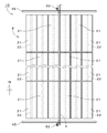
- FIG. 2 is a plan view of the solar heat recovery system 10.
- FIG. 3 is a front view of the solar heat recovery system 10.
- the solar heat recovery system 10 is a Fresnel type solar heat recovery system.
- the up-down direction and the left-right direction in FIG. 2 correspond to the actual north-south direction and east-west direction, for example.
- the lower side and the upper side in FIG. 2 correspond to the south side and the north side, respectively
- the right side and the left side in FIG. 2 correspond to the east side and the west side, respectively.
- the solar heat recovery system 10 includes a reflection unit 2, a reflection unit driving mechanism 3, a receiver 4, a receiver moving mechanism 5, and a control unit 6.
- illustration of the control part 6 is abbreviate
- the receiver 4 is a long tubular body through which a heat medium flows.
- the receiver 4 extends in the north-south direction. Both end portions of the receiver 4 in the north-south direction are supported by a pair of receiver support portions 45. Thereby, the receiver 4 is arrange
- the length and outer diameter of the receiver 4 are not particularly limited, and are, for example, about 98 m and about 70 mm. Although the specific arrangement
- the reflection unit 2 is disposed below the receiver 4.
- the reflection unit 2 reflects sunlight and collects it on the receiver 4.
- the reflection unit 2 includes a plurality of condenser mirrors 21.
- the plurality of condenser mirrors 21 are, for example, the same size and have the same structure.
- the several condensing mirror 21 is arranged in a substantially east-west direction.
- the plurality of collecting mirrors 21 are also arranged in a substantially north-south direction.
- 138 condenser mirrors 21 are arranged in a matrix along the east-west direction and the north-south direction.
- the numbers of the collecting mirrors 21 arranged in the east-west direction and the north-south direction are 6 and 23, respectively.
- the plurality of collecting mirrors 21 are collectively referred to as a “collecting mirror group”, and a central portion in the east-west direction of the collecting mirror group is referred to as a “reflection central portion”.
- the plurality of condenser mirrors 21 may be arranged strictly in the east-west direction and the north-south direction. Alternatively, the arrangement direction of the plurality of collecting mirrors 21 may be slightly deviated from the east-west direction and the north-south direction as long as it can be substantially regarded as the east-west direction and the north-south direction.
- Each condensing mirror 21 is a substantially rectangular substantially flat plate-like member that is long in the north-south direction.
- the width in the east-west direction and the length in the north-south direction of the collector mirror 21 are not particularly limited, but are, for example, about 1.2 m and about 4 m.
- the upper surface of the collector mirror 21 (that is, the main surface facing the receiver 4) is preferably a concave reflecting surface.
- the upper surface of the condensing mirror 21 is a concave surface in which the central portion in the east-west direction is bent downward from both end portions in the east-west direction.
- the cross section perpendicular to the north-south direction on the upper surface of the collector mirror 21 is substantially the same at any position in the north-south direction.
- the cross section of the upper surface of the collector mirror 21 is, for example, substantially parabolic.
- the cross section of the upper surface of the collector mirror 21 may be, for example, a substantially arc shape.
- Each condenser mirror 21 is connected to a mirror rotation shaft 22 extending substantially in the north-south direction.
- the north-south direction is also referred to as the “axial direction”.
- the mirror rotation shaft 22 is located below the condenser mirror 21 and is connected to a substantially central portion in the east-west direction of the condenser mirror 21.
- the condensing mirror 21 can rotate around the mirror rotation axis 22.
- the mirror rotation shaft 22 may extend strictly in the north-south direction, or may extend in a direction slightly shifted from the north-south direction within a range that can be substantially regarded as the north-south direction.
- the reflection unit driving mechanism 3 changes the direction of the reflection unit 2.
- the reflection unit driving mechanism 3 includes a plurality of mirror rotation mechanisms 31 corresponding to the plurality of condenser mirrors 21, respectively.
- the plurality of mirror rotation mechanisms 31 have the same structure, for example.
- the mirror rotating mechanism 31 is disposed on the ground below the condenser mirror 21.
- the mirror rotation mechanism 31 includes, for example, a cylinder portion connected to the condensing mirror 21 from below.
- the reflection unit driving mechanism 3 rotates the plurality of condensing mirrors 21 about the respective mirror rotation axes 22, thereby changing the direction of the reflection unit 2.
- the reflection unit driving mechanism 3 also changes the curvature of the reflection surface of the reflection unit 2. Specifically, the reflector drive mechanism 3 changes the curvature of the upper surface of each condenser mirror 21 (that is, the amount of bending downward of the upper surface).
- the reflection unit driving mechanism 3 includes a plurality of curvature changing mechanisms 32 respectively corresponding to the plurality of condenser mirrors 21.
- the plurality of curvature changing mechanisms 32 change the curvature of the upper surface of the collecting mirror 21 by moving both end portions in the width direction of the collecting mirror 21 upward or downward relative to the central portion. .
- the curvature changing mechanism 32 is connected to, for example, the mirror rotating mechanism 31 and changes the curvature of the upper surface of the collecting mirror 21 in synchronization with the tilt changing of the collecting mirror 21 by the mirror rotating mechanism 31.
- the reflecting portion driving mechanism 3 changes the orientation of the reflecting portion 2 and the curvature of the reflecting surface by rotating the plurality of condensing mirrors 21 about the respective mirror rotation axes 22.
- the tilt change due to the rotation of the condenser mirror 21 and the curvature change of the upper surface of the condenser mirror 21 may be performed independently of each other.
- one mirror rotating mechanism 31 may be provided for the plurality of collecting mirrors 21 arranged in the north-south direction. In this case, when the mirror rotating mechanism 31 is driven, the corresponding plurality of collecting mirrors 21 rotate integrally around the mirror rotation shaft 22, and the orientation of the plurality of collecting mirrors 21 is integrated. Be changed.
- one curvature changing mechanism 32 may be provided for the plurality of collecting mirrors 21, and the curvature of the reflecting surfaces of the plurality of collecting mirrors 21 may be changed integrally.
- the inclination of the collector mirror 21 and the curvature of the reflecting surface are changed in accordance with the movement of the sun at the installation location of the solar heat recovery system 10 so that the reflected light at each position in the width direction of the collector mirror 21 is directed to the receiver 4. Is done.
- the inclination of the collecting mirror 21 and the curvature of the reflecting surface are changed so as to approximately match a parabola set around the receiver 4 on a plane perpendicular to the axial direction in accordance with each altitude of the sun.
- the axis of symmetry of the parabola is a straight line parallel to the sunlight and passing through the receiver 4.
- the focal point of the parabola is the position of the receiver 4.
- the parabola passes through the position of the reflecting surface of the condensing mirror 21 (that is, the center in the width direction of the reflecting surface).
- the reflected light of sunlight can be efficiently guided to the receiver 4 (that is, condensed) by changing the inclination of the condenser mirror 21 and the curvature of the reflecting surface in accordance with the movement of the sun. Realized.
- the receiver moving mechanism 5 includes a receiver connecting portion 51 and a connecting portion rotating mechanism 52.
- the receiver connection unit 51 is connected to the receiver 4 from below.
- the receiver connection unit 51 includes, for example, two receiver arms 53 that extend substantially in the vertical direction. As long as the receiver arm 53 extends substantially in the vertical direction, the receiver arm 53 may extend strictly in the vertical direction, or may extend obliquely along the vertical direction in a direction slightly inclined from the vertical direction. .
- the two receiver arms 53 are disposed in the vicinity of both ends of the receiver 4 in the north-south direction. The upper ends of the two receiver arms 53 are respectively connected to both ends of the receiver 4 in the north-south direction.
- a lower end portion of the receiver arm 53 is rotatably connected to a receiver rotation shaft 54 that is positioned below the receiver 4 and faces in the north-south direction.
- the receiver rotation shaft 54 is preferably arranged near the ground.
- the receiver rotation shaft 54 is disposed approximately 17 cm above the ground.
- connection unit rotation mechanism 52 rotates the receiver connection unit 51 around the receiver rotation shaft 54.
- the connection part rotation mechanism 52 includes, for example, a cylinder part disposed on the ground, and the receiver arm 53 of the receiver connection part 51 rotates about the receiver rotation shaft 54 by expanding and contracting the cylinder part.
- the connection portion rotation mechanism 52 is preferably disposed in the vicinity of the receiver rotation shaft 54.
- the receiver 4 positioned above the above-described reflection central portion is drawn with a solid line.
- the position of the receiver 4 above the reflection central portion and the position of the receiver arm 53 connected to the receiver 4 are referred to as “reference position”.
- the position of the receiver 4 when the receiver arm 53 is rotated about 5 degrees in the clockwise direction in the drawing from the reference position is indicated by a two-dot chain line.
- the receiver 4 moves about 32 cm to the east side from the reference position and moves about 1 cm downward.
- the position of the receiver 4 when the receiver arm 53 is rotated about 5 degrees counterclockwise in the drawing from the reference position is also indicated by a two-dot chain line.
- the position of the receiver 4 indicated by a two-dot chain line is referred to as a “transition position”.
- the receiver 4 moves in the east-west direction substantially horizontally (that is, substantially parallel to the ground).
- the receiver 4 may move strictly horizontally in the east-west direction.
- the receiver 4 may move in the east-west direction while moving slightly in the vertical direction to such an extent that it can be regarded as being substantially horizontal.
- the control unit 6 has a general computer system configuration including, for example, a CPU that performs various arithmetic processes, a ROM that stores basic programs, and a RAM that stores various information.
- the function of the control unit 6 may be realized by a dedicated electrical circuit, or a partially dedicated electrical circuit may be used.
- the control unit 6 controls the reflection unit driving mechanism 3 and the receiver moving mechanism 5 based on the position of the sun. By controlling the receiver moving mechanism 5 by the control unit 6, the receiver 4 moves in the east-west direction above the reflecting unit 2. Further, the control unit 6 controls the reflecting unit driving mechanism 3 to adjust the inclination of the plurality of condensing mirrors 21 and the curvature of the reflecting surface of the reflecting unit 2, and the sunlight incident on each condensing mirror 21 is adjusted. , Reflected toward the receiver 4 and condensed on the receiver 4.
- the receiver moving mechanism 5 when the sun is located on the east side of the median position, the receiver 4 is located on the east side (that is, on the east side of the reflection center). Be placed. Further, when the sun is located at the midline position, the receiver 4 is disposed at the reference position (that is, above the reflection central portion). Furthermore, when the sun is located on the west side from the median position, the receiver 4 is disposed on the west side (that is, on the west side of the reflection central portion) from the reference position.
- the receiver 4 is arranged at a transition position on the east side of the reference position from the sunrise time to 30 minutes before the median time. Then, at 30 minutes before the median time, the receiver 4 moves from the transition position to the reference position. The receiver 4 is arranged at the reference position for one hour from 30 minutes before the mid-time to 30 minutes after the mid-time. Thereafter, at 30 minutes after the median time, the receiver 4 moves from the reference position to the transition position on the west side. The receiver 4 is arranged at a transition position on the west side of the reference position from 30 minutes after the median time to the sunset time.
- the receiver 4 is the transition position or the reference position except when moving from the transition position to the reference position 30 minutes before the median time and when moving from the reference position to the transition position 30 minutes after the median time. Still at position. In other words, the movement of the receiver 4 by the receiver moving mechanism 5 is performed intermittently.
- control of the reflection unit driving mechanism 3 and the receiver moving mechanism 5 is performed indirectly based on the position of the sun by performing the control based on the date and time. Moreover, in the control part 6, control of the reflection part drive mechanism 3 and the receiver moving mechanism 5 is carried out to the position of the sun by performing control based on the irradiation angle of sunlight measured by the solar heat recovery system 10 or the like. It may be performed indirectly. Of course, the control unit 6 may control the reflecting unit driving mechanism 3 and the receiver moving mechanism 5 based directly on the position of the sun measured by the solar heat recovery system 10 or the like.
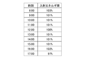
- FIG. 4 is a diagram showing solar energy incident on the receiver 4 when the above-described intermittent movement of the receiver 4 is performed.
- FIG. 4 assumes that the solar heat recovery system 10 is arranged at a position of about 27 degrees east longitude and about 50 degrees north latitude, and the solar energy incident on the receiver 4 on September 25, 2013 is simulated by a ray tracing method. It is what I have requested.
- the surface of the receiver 4 is divided into a large number of small regions, and the total of the calculated incident heat fluxes of the small regions is used as solar energy incident on the receiver 4.
- the simulation result for every hour from 8:00 to 17:00 is shown.
- FIG. 4 the simulation result for every hour from 8:00 to 17:00 is shown.
- the incident energy rate which is the ratio of the sunlight energy which injects into the receiver 4 which moves intermittently with respect to reference
- the reference incident energy is solar energy incident on the receiver 4 when it is assumed that the receiver 4 is located at the reference position at each time.
- the incident energy rate to the receiver 4 is larger than 100% at each time except for 12:00 when the receiver 4 is located at the reference position and 17:00 close to the sunset time.
- the solar energy incident on the receiver 4 is approximately equal at each time compared to the case where the receiver 4 is stationary at the reference position by intermittently moving the receiver 4 as described above. Increase by 1-3%.
- the light collection rate in the receiver 4 can be improved by moving the receiver 4 by the receiver moving mechanism 5.
- the incident energy rate is naturally 100%.
- the Fresnel type solar heat recovery system 10 includes the reflection unit 2, the reflection unit driving mechanism 3, the receiver 4, the receiver moving mechanism 5, and the control unit 6.
- the reflection unit 2 is disposed below the receiver 4 and reflects sunlight to collect the light on the receiver 4.
- the reflector drive mechanism 3 changes the direction of the reflector 2.
- the receiver moving mechanism 5 changes the position of the receiver 4.
- the control unit 6 controls the reflection unit driving mechanism 3 and the receiver moving mechanism 5 based on the position of the sun.
- the light flux of sunlight received by the collector mirror 21 (that is, the light flux proportional to the cosine component of the incident angle of sunlight) can be increased. it can. Therefore, the light collection rate in the receiver 4 can be improved. As a result, the power generation efficiency in the solar thermal power generation system 7 can be improved.
- the receiver 4 extends in the north-south direction.
- the reflection part 2 is provided with the some condensing mirror 21 arranged in the east-west direction.
- Each of the plurality of condenser mirrors 21 is rotatable around a mirror rotation axis 22 extending in the north-south direction.
- the reflection unit driving mechanism 3 changes the direction of the reflection unit 2 by rotating the plurality of condenser mirrors 21 about the respective mirror rotation axes 22.
- the receiver moving mechanism 5 is controlled by the control unit 6, when the sun is located on the east side from the median position, the receiver 4 is the central part in the east-west direction of the collecting mirror group that is the plurality of collecting mirrors 21. It is arranged on the east side of the reflection central part.
- the receiver 4 when the sun is located at the midline position, the receiver 4 is disposed above the reflection central portion. Furthermore, when the sun is located on the west side from the median position, the receiver 4 is arranged on the west side from the reflection central part. Thereby, the condensing rate in the receiver 4 can be improved while simplifying the movement of the receiver 4.
- the receiver 4 is moved intermittently by the receiver moving mechanism 5. Thereby, compared with the case where the receiver 4 is moved continuously, the power required for the movement of the receiver 4 during one day can be reduced. Further, the movement control of the receiver 4 by the control unit 6 can be facilitated.
- the receiver moving mechanism 5 includes the receiver connecting portion 51 and the connecting portion rotating mechanism 52.
- the receiver connection unit 51 is connected to the receiver 4 from below.
- the connection part rotation mechanism 52 changes the position of the receiver 4 by rotating the receiver connection part 51 around the receiver rotation shaft 54 positioned below the receiver 4. Thereby, the movement of the receiver 4 is realizable with a simple structure.
- the receiver rotation shaft 54 is positioned below the receiver 4, maintenance of the receiver rotation shaft 54 and the connection portion rotation mechanism 52 can be facilitated.
- the reflection unit 2 includes a condensing mirror 21 whose upper surface is a concave reflection surface. Thereby, the light beam of the reflected light by the condensing mirror 21 can be converged, and the condensing rate in the receiver 4 can be further improved. From the viewpoint of further improving the light collection rate, the receiver 4 is preferably arranged in the vicinity of the focal position of the light collection mirror 21.
- the curvature of the reflecting surface of each condensing mirror 21 is also changed by the control unit 6 controlling the reflecting unit drive mechanism 3 based on the position of the sun. Thereby, the condensing rate in the receiver 4 can further be improved.
- the movement mode of the receiver 4 by the receiver moving mechanism 5 is not limited to the above example, and may be variously changed.
- the movement of the receiver 4 by the receiver moving mechanism 5 may be performed continuously.
- the receiver 4 may continue to move based on the position of the sun from the sunrise time to the sunset time.
- the receiver 4 can be arrange
- the receiver 4 may be moved in the vertical direction.
- the receiver moving mechanism 5 does not necessarily have to move the receiver 4 by the rotational movement of the receiver connecting portion 51.
- the structure of the receiver moving mechanism 5 may be variously changed from the above structure.
- the number of the receivers 4 and the collecting mirrors 21 may be variously changed.
- a plurality of receivers 4 may be disposed above the reflection unit 2.
- all or some positions of the plurality of receivers 4 are changed by the receiver moving mechanism 5 based on the position of the sun.
- the plurality of condensing mirrors 21 may be arranged in a line in a substantially east-west direction and may not be arranged in a substantially north-south direction.
- the shape of the reflecting surface of the condensing mirror 21 is not necessarily concave as long as it can reflect sunlight and collect it on the receiver 4, and may be variously changed.
- the solar heat recovery system 10 may be used in various facilities other than the solar thermal power generation system 7. In other words, the solar heat recovered by the solar heat recovery system 10 may be used for purposes other than power generation.
Landscapes
- Engineering & Computer Science (AREA)
- Physics & Mathematics (AREA)
- Life Sciences & Earth Sciences (AREA)
- Sustainable Development (AREA)
- Sustainable Energy (AREA)
- Thermal Sciences (AREA)
- Chemical & Material Sciences (AREA)
- Combustion & Propulsion (AREA)
- Mechanical Engineering (AREA)
- General Engineering & Computer Science (AREA)
- Photovoltaic Devices (AREA)
- Optical Elements Other Than Lenses (AREA)
Abstract
フレネル型の太陽熱回収システム(10)は、反射部(2)と、反射部駆動機構(3)と、レシーバ(4)と、レシーバ移動機構(5)と、制御部(6)とを備える。反射部(2)は、レシーバ(4)の下方に配置され、太陽光を反射してレシーバ(4)に集光する。反射部駆動機構(3)は、反射部(2)の向きを変更する。レシーバ移動機構(5)は、レシーバ(4)の位置を変更する。制御部(6)は、太陽の位置に基づいて反射部駆動機構(3)およびレシーバ移動機構(5)を制御する。これにより、レシーバの移動が行われない従来の太陽熱回収システムに比べて、レシーバ(4)における集光率を向上することができる。その結果、太陽熱発電システムにおける発電効率を向上することができる。
Description
本発明は、太陽熱回収システムに関する。
近年、再生可能エネルギとして太陽光の利用が注目されている。集光型太陽熱発電(CSP:concentrating solar power)は、太陽光エネルギを利用して発電を行う方法の1つである。集光型太陽熱発電には、様々な種類がある。
例えば、トラフ型の太陽熱発電システムでは、断面が放物線状であるトラフ型の反射鏡により、当該反射鏡の焦点上に配置された集熱管に太陽光を集光し、集められた太陽熱を利用して発電が行われる。特開2012-117763号公報(文献1)の太陽光集光装置では、反射鏡および集熱管を一体的な揺動体として構成し、太陽の方向に合わせて当該揺動体を回転させる。これにより、揺動体を回転させる機構におけるバックラッシュの解消が図られている。
一方、フレネル型の太陽熱発電システムでは、複数の集光ミラーの上方に固定されたレシーバに、当該複数の集光ミラーにより太陽光を集光し、集められた太陽熱を利用して発電が行われる。フレネル型の太陽熱発電システムでは、集光ミラーで受ける太陽光の光束は、太陽光の入射角度のコサイン成分に比例する。このため、朝方や夕方等のように、太陽光が大きな入射角度で集光ミラーに入射する場合、集光ミラーが受けることのできる太陽光エネルギが低下する。
そこで、特開2014-20749号公報(文献2)のフレネル型の太陽熱発電システムでは、第1および第2のレシーバを設け、選択集光ミラーへの太陽光の入射角度が小さくなるように、選択集光ミラーによる集光の対象を、第1および第2のレシーバの間で切り替える。これにより、選択集光ミラーによる集光率の向上が図られている。
ところで、文献2の太陽熱発電システムでは、1つの選択集光ミラーに対して2つのレシーバを設ける必要があり、システムが大型化するおそれがある。また、太陽の位置によっては、2つのレシーバのいずれに集光したとしても、選択集光ミラーへの太陽光の入射角度があまり小さくならない場合もあり、選択集光ミラーによる集光率の向上に限界がある。
本発明は、太陽熱回収システムに向けられており、レシーバにおける集光率を向上することを目的としている。
本発明に係るフレネル型の太陽熱回収システムは、レシーバと、前記レシーバの下方に配置され、太陽光を反射して前記レシーバに集光する反射部と、前記反射部の向きを変更する反射部駆動機構と、前記レシーバの位置を変更するレシーバ移動機構と、太陽の位置に基づいて前記反射部駆動機構および前記レシーバ移動機構を制御する制御部とを備える。当該太陽熱回収システムによれば、レシーバにおける集光率を向上することができる。
本発明の一の好ましい実施の形態では、前記レシーバが、南北方向に延び、前記反射部が、東西方向に配列されるとともにそれぞれが南北方向に延びるミラー回転軸を中心として回転可能な複数の集光ミラーを備え、前記反射部駆動機構が、前記複数の集光ミラーをそれぞれの前記ミラー回転軸を中心として回転させることにより、前記反射部の向きを変更し、前記レシーバ移動機構が前記制御部により制御されることにより、太陽が正中位置よりも東側に位置するときに、前記レシーバが、前記複数の集光ミラーである集光ミラー群の東西方向の中央部である反射中央部よりも東側に配置され、太陽が前記正中位置に位置するときに、前記レシーバが前記反射中央部の上方に配置され、太陽が前記正中位置よりも西側に位置するときに、前記レシーバが前記反射中央部よりも西側に配置される。
本発明の他の好ましい実施の形態では、前記レシーバ移動機構が、前記レシーバに下方から接続されるレシーバ接続部と、前記レシーバよりも下方に位置するレシーバ回転軸を中心として前記レシーバ接続部を回転することにより、前記レシーバの位置を変更する接続部回転機構とを備える。
上述の目的および他の目的、特徴、態様および利点は、添付した図面を参照して以下に行うこの発明の詳細な説明により明らかにされる。
図1は、本発明の一の実施の形態に係る太陽熱発電システム7の構成を示す図である。太陽熱発電システム7は、太陽熱回収システム10と、発電部71とを備える。太陽熱回収システム10では、太陽熱を利用して、後述するレシーバ4内を流れる熱媒体が加熱される。換言すれば、太陽熱回収システム10により、熱媒体を利用して太陽熱が回収される。
太陽熱回収システム10において加熱された熱媒体は、発電部71との間で循環される。発電部71では、熱媒体が有する熱(すなわち、レシーバ4にて得られた熱)を利用して発電が行われる。発電部71では、例えば、熱媒体が有する熱を利用して作動流体が気化され、気化された作動流体により蒸気タービンが駆動されることにより、蒸気タービンに接続された発電機による発電が行われる。
図2は、太陽熱回収システム10の平面図である。図3は、太陽熱回収システム10の正面図である。太陽熱回収システム10は、フレネル型の太陽熱回収システムである。図2中の上下方向および左右方向は、例えば、実際の南北方向および東西方向に対応する。具体的には、図2中の下側および上側がそれぞれ南側および北側に対応し、図2中の右側および左側がそれぞれ東側および西側に対応する。
太陽熱回収システム10は、反射部2と、反射部駆動機構3と、レシーバ4と、レシーバ移動機構5と、制御部6と、を備える。なお、図2では、制御部6の図示を省略している。レシーバ4は、内部を熱媒体が流れる長い管状体である。レシーバ4は、南北方向に延びる。レシーバ4の南北方向の両端部は、一対のレシーバ支持部45により支持される。これにより、レシーバ4が、反射部2等の上方に配置される。レシーバ4の長さおよび外径は特に限定されないが、例えば、約98mおよび約70mmである。レシーバ4の具体的な配置は特に限定されないが、例えば、地面から約3.8m上方に配置される。
反射部2は、レシーバ4の下方に配置される。反射部2は、太陽光を反射してレシーバ4に集光する。反射部2は、複数の集光ミラー21を備える。複数の集光ミラー21は、例えば、同じ大きさであり、互いに同じ構造を有する。複数の集光ミラー21は、略東西方向に配列される。複数の集光ミラー21は、また、略南北方向にも配列される。図1および図2に示す例では、138個の集光ミラー21が、東西方向および南北方向に沿ってマトリクス状に配置される。東西方向および南北方向にそれぞれ並ぶ集光ミラー21の数は、6および23である。以下の説明では、当該複数の集光ミラー21をまとめて「集光ミラー群」と呼び、当該集光ミラー群の東西方向の中央部を「反射中央部」と呼ぶ。なお、複数の集光ミラー21は、厳密に東西方向および南北方向に配列されてもよい。あるいは、複数の集光ミラー21の配列方向は、実質的に東西方向および南北方向と捉えられるのであれば、東西方向および南北方向から僅かにずれていてもよい。
各集光ミラー21は、南北方向に長い略長方形の略平板状部材である。集光ミラー21の東西方向の幅、および、南北方向の長さは特に限定されないが、例えば、約1.2mおよび約4mである。集光ミラー21の上面(すなわち、レシーバ4を向く主面)は、好ましくは、凹状の反射面である。集光ミラー21の上面は、東西方向の中央部が東西方向の両端部よりも下方に向かって撓む凹面である。集光ミラー21の上面の南北方向に垂直な断面は、南北方向のいずれの位置においても略同じである。集光ミラー21の上面の上記断面は、例えば、略放物線状である。集光ミラー21の上面の上記断面は、例えば、略円弧状であってもよい。
各集光ミラー21は、略南北方向に延びるミラー回転軸22に接続される。以下の説明では、南北方向を「軸方向」ともいう。ミラー回転軸22は、集光ミラー21の下方に位置し、集光ミラー21の東西方向における略中央部に接続される。集光ミラー21は、ミラー回転軸22を中心として回転可能である。なお、ミラー回転軸22は、厳密に南北方向に延びていてもよく、実質的に南北方向と捉えられる範囲で、南北方向から僅かにずれた方向に延びていてもよい。
反射部駆動機構3は、反射部2の向きを変更する。反射部駆動機構3は、複数の集光ミラー21にそれぞれ対応する複数のミラー回転機構31を備える。複数のミラー回転機構31は、例えば、互いに同じ構造を有する。ミラー回転機構31は、集光ミラー21の下方において地面に配置される。ミラー回転機構31は、例えば、集光ミラー21に下側から接続されるシリンダ部等を備える。ミラー回転機構31が駆動されることにより、ミラー回転機構31の上方に位置する集光ミラー21が、ミラー回転軸22を中心として回転し、集光ミラー21の上面の傾きが変更される。太陽熱回収システム10では、反射部駆動機構3が、複数の集光ミラー21をそれぞれのミラー回転軸22を中心として回転させることにより、反射部2の向きが変更される。
反射部駆動機構3は、また、反射部2の反射面の曲率を変更する。具体的には、反射部駆動機構3は、各集光ミラー21の上面の曲率(すなわち、当該上面の下方への撓み量)を変更する。反射部駆動機構3は、複数の集光ミラー21にそれぞれ対応する複数の曲率変更機構32を備える。複数の曲率変更機構32は、例えば、集光ミラー21の幅方向の両端部を中央部に対して相対的に上方または下方へと移動することにより、集光ミラー21の上面の曲率を変更する。
曲率変更機構32は、例えば、ミラー回転機構31に連結され、ミラー回転機構31による集光ミラー21の傾き変更に同期して、集光ミラー21の上面の曲率を変更する。この場合、反射部駆動機構3は、複数の集光ミラー21をそれぞれのミラー回転軸22を中心として回転させることにより、反射部2の向きおよび反射面の曲率を変更する。なお、反射部駆動機構3では、集光ミラー21の回転による傾き変更と、集光ミラー21の上面の曲率変更とは、互いに独立して行われてもよい。
反射部駆動機構3では、南北方向に並ぶ複数の集光ミラー21に対して1つのミラー回転機構31が設けられてもよい。この場合、当該ミラー回転機構31が駆動されることにより、対応する複数の集光ミラー21がミラー回転軸22を中心として一体的に回転し、当該複数の集光ミラー21の向きが一体的に変更される。また、当該複数の集光ミラー21に対して1つの曲率変更機構32が設けられ、当該複数の集光ミラー21の反射面の曲率が一体的に変更されてもよい。
集光ミラー21の傾きおよび反射面の曲率は、集光ミラー21の幅方向の各位置における反射光がレシーバ4へと向かうように、太陽熱回収システム10の設置場所における太陽の動きに合わせて変更される。例えば、集光ミラー21の傾きおよび反射面の曲率は、太陽の各高度に合わせて、軸方向に垂直な面上においてレシーバ4の周囲に設定された放物線におよそ一致するように変更される。当該放物線の対称軸は、太陽光に平行、かつ、レシーバ4を通過する直線である。また、当該放物線の焦点は、レシーバ4の位置である。さらに、当該放物線は、集光ミラー21の反射面の位置(すなわち、反射面の幅方向の中央)を通る。このように、集光ミラー21の傾きおよび反射面の曲率が、太陽の動きに合わせて変更されることにより、太陽光の反射光を効率良くレシーバ4に導く(すなわち、集光する)ことが実現される。
レシーバ移動機構5は、レシーバ接続部51と、接続部回転機構52とを備える。レシーバ接続部51は、レシーバ4に下方から接続される。レシーバ接続部51は、例えば、略上下方向に延びる2つのレシーバアーム53を備える。レシーバアーム53は、実質的に上下方向に延びているのであれば、厳密に上下方向に延びていてもよく、上下方向から少し傾いた方向へと上下方向に沿って斜めに延びていてもよい。2つのレシーバアーム53はそれぞれ、レシーバ4の南北方向の両端部近傍に配置される。2つのレシーバアーム53の上端部はそれぞれ、レシーバ4の南北方向の両端部に接続される。レシーバアーム53の下端部は、レシーバ4よりも下方に位置して南北方向を向くレシーバ回転軸54に、回転可能に接続される。レシーバ回転軸54は、好ましくは、地面近傍に配置される。レシーバ回転軸54は、例えば、地面から約17cm上方に配置される。
接続部回転機構52は、レシーバ回転軸54を中心としてレシーバ接続部51を回転する。接続部回転機構52は、例えば、地面に配置されたシリンダ部等を備え、当該シリンダ部を伸縮させることにより、レシーバ接続部51のレシーバアーム53が、レシーバ回転軸54を中心として回転する。接続部回転機構52は、好ましくは、レシーバ回転軸54の近傍に配置される。レシーバ移動機構5において接続部回転機構52が駆動されてレシーバ接続部51が回転することにより、反射部2の上方においてレシーバ4の位置が東西方向に変更される。
図3では、上述の反射中央部の上方に位置するレシーバ4を実線にて描く。以下の説明では、反射中央部の上方のレシーバ4の位置、および、当該レシーバ4に接続されたレシーバアーム53の位置を「基準位置」という。図3では、レシーバアーム53を基準位置から図中の時計回り方向に約5度回転させた場合のレシーバ4の位置を二点鎖線にて示す。このとき、レシーバ4は基準位置から東側に約32cm移動し、下方に約1cm移動する。図3では、レシーバアーム53を基準位置から図中の反時計回り方向に約5度回転させた場合のレシーバ4の位置も二点鎖線にて示す。以下の説明では、二点鎖線にて示すレシーバ4の位置を「変移位置」という。図3に示す例では、レシーバ4は、略水平に(すなわち、地面に略平行に)東西方向に移動する。なお、レシーバ4は、厳密に水平に東西方向に移動してもよい。あるいは、レシーバ4は、実質的に水平と捉えられる程度に上下方向に僅かに移動しつつ東西方向に移動してもよい。
制御部6は、例えば、各種演算処理を行うCPUと、基本プログラムを記憶するROMと、各種情報を記憶するRAMとを含む一般的なコンピュータシステムの構成となっている。制御部6の機能は専用の電気的回路により実現されてもよく、部分的に専用の電気的回路が用いられてもよい。
制御部6は、太陽の位置に基づいて反射部駆動機構3およびレシーバ移動機構5を制御する。制御部6によりレシーバ移動機構5が制御されることにより、レシーバ4が反射部2の上方において東西方向に移動する。また、制御部6により反射部駆動機構3が制御されることにより、反射部2の複数の集光ミラー21の傾きおよび反射面の曲率が調整され、各集光ミラー21に入射した太陽光が、レシーバ4に向けて反射されてレシーバ4に集光される。
例えば、レシーバ移動機構5が制御部6により制御されることにより、太陽が正中位置よりも東側に位置するときに、レシーバ4は、基準位置よりも東側(すなわち、反射中央部よりも東側)に配置される。また、太陽が正中位置に位置するときに、レシーバ4は、基準位置(すなわち、反射中央部の上方)に配置される。さらに、太陽が正中位置よりも西側に位置するときに、レシーバ4は基準位置よりも西側(すなわち、反射中央部よりも西側)に配置される。
具体的には、例えば、日の出時刻から正中時刻の30分前までの間、レシーバ4は、基準位置よりも東側の変移位置に配置される。そして、正中時刻の30分前になると、レシーバ4は上記変移位置から基準位置へと移動する。レシーバ4は、正中時刻の30分前から正中時刻の30分後までの1時間の間、基準位置に配置される。その後、正中時刻の30分後になると、レシーバ4は基準位置から西側の変移位置へと移動する。レシーバ4は、正中時刻の30分後から日没時刻までの間、基準位置よりも西側の変移位置に配置される。
上記例では、レシーバ4は、正中時刻の30分前における変移位置から基準位置への移動時、および、正中時刻の30分後における基準位置から変移位置への移動時を除き、変移位置または基準位置にて静止している。換言すれば、レシーバ移動機構5によるレシーバ4の移動は、断続的に行われる。
上述の制御部6では、日時に基づいて制御が行われることにより、反射部駆動機構3およびレシーバ移動機構5の制御が、太陽の位置に間接的に基づいて行われる。また、制御部6では、太陽熱回収システム10等にて測定された太陽光の照射角度に基づいて制御が行われることにより、反射部駆動機構3およびレシーバ移動機構5の制御が、太陽の位置に間接的に基づいて行われてもよい。制御部6では、当然ながら、太陽熱回収システム10等にて測定された太陽の位置に直接的に基づいて、反射部駆動機構3およびレシーバ移動機構5の制御が行われてもよい。
図4は、レシーバ4の上述の断続的移動が行われた場合において、レシーバ4に入射する太陽光エネルギを示す図である。図4は、太陽熱回収システム10が東経約27度かつ北緯約50度の位置に配置されたと仮定し、2013年9月25日におけるレシーバ4に入射する太陽光エネルギを、光線追跡法によるシミュレーションにより求めたものである。シミュレーションでは、レシーバ4表面を多数の小領域に分割し、算出された各小領域の入射熱流束の合計を、レシーバ4に入射する太陽光エネルギとしている。図4では、8時から17時までの1時間毎のシミュレーション結果を示す。図4では、各時刻において、基準入射エネルギに対する、断続的に移動するレシーバ4に入射する太陽光エネルギの割合である入射エネルギ率を示す。基準入射エネルギは、各時刻において、レシーバ4が基準位置に位置すると仮定した場合にレシーバ4に入射する太陽光エネルギである。
図4に示すように、レシーバ4が基準位置に位置する12時、および、日没時刻に近い17時を除き、レシーバ4への入射エネルギ率は各時刻において100%よりも大きい。具体的には、レシーバ4に入射する太陽光エネルギは、上述のようにレシーバ4を断続的に移動することにより、レシーバ4を基準位置にて静止させておく場合に比べて、各時刻において約1~3%増大する。換言すれば、レシーバ移動機構5によりレシーバ4を移動することにより、レシーバ4における集光率を向上することができる。なお、レシーバ4が基準位置に位置する12時では、当然ながら、入射エネルギ率は100%である。
以上に説明したように、フレネル型の太陽熱回収システム10は、反射部2と、反射部駆動機構3と、レシーバ4と、レシーバ移動機構5と、制御部6とを備える。反射部2は、レシーバ4の下方に配置され、太陽光を反射してレシーバ4に集光する。反射部駆動機構3は、反射部2の向きを変更する。レシーバ移動機構5は、レシーバ4の位置を変更する。制御部6は、太陽の位置に基づいて反射部駆動機構3およびレシーバ移動機構5を制御する。
これにより、レシーバの移動が行われない従来の太陽熱回収システムに比べて、集光ミラー21で受ける太陽光の光束(すなわち、太陽光の入射角度のコサイン成分に比例する光束)を大きくすることができる。したがって、レシーバ4における集光率を向上することができる。その結果、太陽熱発電システム7における発電効率を向上することができる。
上述のように、レシーバ4は南北方向に延びる。また、反射部2は、東西方向に配列される複数の集光ミラー21を備える。複数の集光ミラー21のそれぞれは、南北方向に延びるミラー回転軸22を中心として回転可能である。反射部駆動機構3は、複数の集光ミラー21をそれぞれのミラー回転軸22を中心として回転させることにより、反射部2の向きを変更する。レシーバ移動機構5が制御部6により制御されることにより、太陽が正中位置よりも東側に位置するときに、レシーバ4が、複数の集光ミラー21である集光ミラー群の東西方向の中央部である反射中央部よりも東側に配置される。また、太陽が正中位置に位置するときに、レシーバ4が反射中央部の上方に配置される。さらに、太陽が正中位置よりも西側に位置するときに、レシーバ4が反射中央部よりも西側に配置される。これにより、レシーバ4の移動を簡素化しつつ、レシーバ4における集光率を向上することができる。
太陽熱回収システム10では、レシーバ移動機構5によるレシーバ4の移動が、断続的に行われる。これにより、レシーバ4を連続的に移動する場合に比べて、1日の間にレシーバ4の移動に要する動力を低減することができる。また、制御部6によるレシーバ4の移動制御を容易とすることができる。
上述のように、レシーバ移動機構5は、レシーバ接続部51と、接続部回転機構52とを備える。レシーバ接続部51は、レシーバ4に下方から接続される。接続部回転機構52は、レシーバ4よりも下方に位置するレシーバ回転軸54を中心としてレシーバ接続部51を回転することにより、レシーバ4の位置を変更する。これにより、簡素な構造によりレシーバ4の移動を実現することができる。また、レシーバ回転軸54がレシーバ4よりも下方に位置するため、レシーバ回転軸54および接続部回転機構52のメンテナンスを容易とすることもできる。
太陽熱回収システム10では、反射部2が、上面が凹状の反射面である集光ミラー21を備える。これにより、集光ミラー21による反射光の光束を収束させることができ、レシーバ4における集光率をさらに向上することができる。集光率の更なる向上という観点からは、レシーバ4は、集光ミラー21の焦点位置近傍に配置されることが好ましい。
また、太陽熱回収システム10では、制御部6が太陽の位置に基づいて反射部駆動機構3を制御することにより、各集光ミラー21の反射面の曲率も変更される。これにより、レシーバ4における集光率をさらに向上することができる。
上述の太陽熱回収システム10および太陽熱発電システム7では、様々な変更が可能である。
太陽熱回収システム10では、レシーバ移動機構5によるレシーバ4の移動態様は上述の例には限定されず、様々に変更されてよい。例えば、レシーバ移動機構5によるレシーバ4の移動は、連続的に行われてもよい。具体的には、レシーバ4は、日の出時刻から日没時刻まで、太陽の位置に基づいて移動し続けてもよい。これにより、レシーバ4を各時刻において集光に最適な位置に配置することができ、レシーバ4における集光率をさらに向上することができる。また、レシーバ4は、上下方向に移動されてもよい。
レシーバ移動機構5は、必ずしもレシーバ接続部51の回転運動によりレシーバ4を移動するものでなくてよい。レシーバ移動機構5の構造は、上述の構造から様々に変更されてよい。
太陽熱回収システム10では、レシーバ4および集光ミラー21の数は様々に変更されてよい。例えば、反射部2の上方に複数のレシーバ4が配置されてもよい。この場合、当該複数のレシーバ4の全てまたは一部の位置が、太陽の位置に基づいてレシーバ移動機構5により変更される。複数の集光ミラー21は、例えば、略東西方向に1列に配列され、略南北方向には配列されなくてもよい。
集光ミラー21の反射面の形状は、太陽光を反射してレシーバ4に集光することができるのであれば、必ずしも凹状である必要はなく、様々に変更されてよい。
太陽熱回収システム10は、太陽熱発電システム7以外の様々な設備において利用されてよい。換言すれば、太陽熱回収システム10により回収された太陽熱は、発電以外の目的に利用されてもよい。
上記実施の形態および各変形例における構成は、相互に矛盾しない限り適宜組み合わされてよい。
発明を詳細に描写して説明したが、既述の説明は例示的であって限定的なものではない。したがって、本発明の範囲を逸脱しない限り、多数の変形や態様が可能であるといえる。
2 反射部
3 反射部駆動機構
4 レシーバ
5 レシーバ移動機構
6 制御部
10 太陽熱回収システム
21 集光ミラー
22 ミラー回転軸
51 レシーバ接続部
52 接続部回転機構
3 反射部駆動機構
4 レシーバ
5 レシーバ移動機構
6 制御部
10 太陽熱回収システム
21 集光ミラー
22 ミラー回転軸
51 レシーバ接続部
52 接続部回転機構
Claims (3)
- フレネル型の太陽熱回収システムであって、
レシーバと、
前記レシーバの下方に配置され、太陽光を反射して前記レシーバに集光する反射部と、
前記反射部の向きを変更する反射部駆動機構と、
前記レシーバの位置を変更するレシーバ移動機構と、
太陽の位置に基づいて前記反射部駆動機構および前記レシーバ移動機構を制御する制御部と、
を備える。 - 請求項1に記載の太陽熱回収システムであって、
前記レシーバが、南北方向に延び、
前記反射部が、東西方向に配列されるとともにそれぞれが南北方向に延びるミラー回転軸を中心として回転可能な複数の集光ミラーを備え、
前記反射部駆動機構が、前記複数の集光ミラーをそれぞれの前記ミラー回転軸を中心として回転させることにより、前記反射部の向きを変更し、
前記レシーバ移動機構が前記制御部により制御されることにより、
太陽が正中位置よりも東側に位置するときに、前記レシーバが、前記複数の集光ミラーである集光ミラー群の東西方向の中央部である反射中央部よりも東側に配置され、
太陽が前記正中位置に位置するときに、前記レシーバが前記反射中央部の上方に配置され、
太陽が前記正中位置よりも西側に位置するときに、前記レシーバが前記反射中央部よりも西側に配置される。 - 請求項1または2に記載の太陽熱回収システムであって、
前記レシーバ移動機構が、
前記レシーバに下方から接続されるレシーバ接続部と、
前記レシーバよりも下方に位置するレシーバ回転軸を中心として前記レシーバ接続部を回転することにより、前記レシーバの位置を変更する接続部回転機構と、
を備える。
Priority Applications (1)
| Application Number | Priority Date | Filing Date | Title |
|---|---|---|---|
| PCT/JP2016/055634 WO2017145328A1 (ja) | 2016-02-25 | 2016-02-25 | 太陽熱回収システム |
Applications Claiming Priority (1)
| Application Number | Priority Date | Filing Date | Title |
|---|---|---|---|
| PCT/JP2016/055634 WO2017145328A1 (ja) | 2016-02-25 | 2016-02-25 | 太陽熱回収システム |
Publications (1)
| Publication Number | Publication Date |
|---|---|
| WO2017145328A1 true WO2017145328A1 (ja) | 2017-08-31 |
Family
ID=59686010
Family Applications (1)
| Application Number | Title | Priority Date | Filing Date |
|---|---|---|---|
| PCT/JP2016/055634 Ceased WO2017145328A1 (ja) | 2016-02-25 | 2016-02-25 | 太陽熱回収システム |
Country Status (1)
| Country | Link |
|---|---|
| WO (1) | WO2017145328A1 (ja) |
Citations (5)
| Publication number | Priority date | Publication date | Assignee | Title |
|---|---|---|---|---|
| WO1996029745A1 (en) * | 1995-03-23 | 1996-09-26 | Helfgott & Karas, P.C. | Solar collection system |
| JP2010002164A (ja) * | 2008-06-23 | 2010-01-07 | Kokusai Gijutsu Kaihatsu Co Ltd | 太陽熱収集システム |
| JP2012122642A (ja) * | 2010-12-07 | 2012-06-28 | Hitachi Plant Technologies Ltd | 太陽光集熱装置 |
| WO2013051316A1 (ja) * | 2011-10-05 | 2013-04-11 | 住友重機械工業株式会社 | 太陽集光システム及び太陽熱発電システム |
| JP2015056436A (ja) * | 2013-09-10 | 2015-03-23 | 株式会社SolarFlame | 太陽光集光発電装置 |
-
2016
- 2016-02-25 WO PCT/JP2016/055634 patent/WO2017145328A1/ja not_active Ceased
Patent Citations (5)
| Publication number | Priority date | Publication date | Assignee | Title |
|---|---|---|---|---|
| WO1996029745A1 (en) * | 1995-03-23 | 1996-09-26 | Helfgott & Karas, P.C. | Solar collection system |
| JP2010002164A (ja) * | 2008-06-23 | 2010-01-07 | Kokusai Gijutsu Kaihatsu Co Ltd | 太陽熱収集システム |
| JP2012122642A (ja) * | 2010-12-07 | 2012-06-28 | Hitachi Plant Technologies Ltd | 太陽光集熱装置 |
| WO2013051316A1 (ja) * | 2011-10-05 | 2013-04-11 | 住友重機械工業株式会社 | 太陽集光システム及び太陽熱発電システム |
| JP2015056436A (ja) * | 2013-09-10 | 2015-03-23 | 株式会社SolarFlame | 太陽光集光発電装置 |
Similar Documents
| Publication | Publication Date | Title |
|---|---|---|
| US8365719B2 (en) | Multi-receiver heliostat system architecture | |
| CN101806502B (zh) | 定目镜太阳能集热系统 | |
| CN102138046B (zh) | 线性太阳能热发电系统 | |
| US20130098354A1 (en) | Solar collectors | |
| WO2011086825A1 (ja) | 太陽光集光装置および太陽熱回収設備 | |
| CN102721195B (zh) | 太阳能聚光跟踪阵列水平定向汇集装置 | |
| IL194840A (en) | Hyperbolic system using a solar field | |
| JP6342632B2 (ja) | 太陽光集光発電装置 | |
| JP3855160B2 (ja) | 太陽放射集中装置 | |
| CN202660771U (zh) | 太阳能聚光跟踪阵列水平定向汇集装置 | |
| WO2017145328A1 (ja) | 太陽熱回収システム | |
| CN106679198A (zh) | 一种太阳能聚光装置 | |
| CN201652878U (zh) | 定目镜太阳能集热系统 | |
| JP2012169570A (ja) | 太陽光発電装置 | |
| KR20170032635A (ko) | LFR(Linear Fresnel Reflector)를 이용한 집광 방법 및 장치 | |
| JP2014135365A (ja) | 太陽光集光発電装置 | |
| JP2011129847A (ja) | 反射集光型太陽発電モジュール | |
| WO2013005479A1 (ja) | 太陽集光システム及び太陽熱発電システム | |
| JP2015049005A (ja) | 太陽熱集熱装置 | |
| JPS6127667B2 (ja) | ||
| CN112665201A (zh) | 免追踪太阳能聚光系统 | |
| RU2554168C1 (ru) | Способ получения тепловой и электрической энергии и устройство для его осуществления | |
| JP6231737B2 (ja) | 太陽熱集熱装置 | |
| JP2014163629A (ja) | 太陽光集光装置 | |
| JP2011094820A (ja) | 太陽光集光受熱システム |
Legal Events
| Date | Code | Title | Description |
|---|---|---|---|
| NENP | Non-entry into the national phase |
Ref country code: DE |
|
| 121 | Ep: the epo has been informed by wipo that ep was designated in this application |
Ref document number: 16891485 Country of ref document: EP Kind code of ref document: A1 |
|
| 122 | Ep: pct application non-entry in european phase |
Ref document number: 16891485 Country of ref document: EP Kind code of ref document: A1 |
|
| NENP | Non-entry into the national phase |
Ref country code: JP |