WO2017138486A1 - 昇圧システム - Google Patents
昇圧システム Download PDFInfo
- Publication number
- WO2017138486A1 WO2017138486A1 PCT/JP2017/004204 JP2017004204W WO2017138486A1 WO 2017138486 A1 WO2017138486 A1 WO 2017138486A1 JP 2017004204 W JP2017004204 W JP 2017004204W WO 2017138486 A1 WO2017138486 A1 WO 2017138486A1
- Authority
- WO
- WIPO (PCT)
- Prior art keywords
- pressure
- unit
- cooling
- flow rate
- compression
- Prior art date
- Legal status (The legal status is an assumption and is not a legal conclusion. Google has not performed a legal analysis and makes no representation as to the accuracy of the status listed.)
- Ceased
Links
Images



Classifications
-
- F—MECHANICAL ENGINEERING; LIGHTING; HEATING; WEAPONS; BLASTING
- F04—POSITIVE - DISPLACEMENT MACHINES FOR LIQUIDS; PUMPS FOR LIQUIDS OR ELASTIC FLUIDS
- F04D—NON-POSITIVE-DISPLACEMENT PUMPS
- F04D17/00—Radial-flow pumps, e.g. centrifugal pumps; Helico-centrifugal pumps
- F04D17/08—Centrifugal pumps
- F04D17/10—Centrifugal pumps for compressing or evacuating
- F04D17/12—Multi-stage pumps
-
- F—MECHANICAL ENGINEERING; LIGHTING; HEATING; WEAPONS; BLASTING
- F04—POSITIVE - DISPLACEMENT MACHINES FOR LIQUIDS; PUMPS FOR LIQUIDS OR ELASTIC FLUIDS
- F04D—NON-POSITIVE-DISPLACEMENT PUMPS
- F04D29/00—Details, component parts, or accessories
- F04D29/58—Cooling; Heating; Diminishing heat transfer
- F04D29/582—Cooling; Heating; Diminishing heat transfer specially adapted for elastic fluid pumps
- F04D29/5826—Cooling at least part of the working fluid in a heat exchanger
- F04D29/5833—Cooling at least part of the working fluid in a heat exchanger flow schemes and regulation thereto
-
- F—MECHANICAL ENGINEERING; LIGHTING; HEATING; WEAPONS; BLASTING
- F25—REFRIGERATION OR COOLING; COMBINED HEATING AND REFRIGERATION SYSTEMS; HEAT PUMP SYSTEMS; MANUFACTURE OR STORAGE OF ICE; LIQUEFACTION SOLIDIFICATION OF GASES
- F25J—LIQUEFACTION, SOLIDIFICATION OR SEPARATION OF GASES OR GASEOUS OR LIQUEFIED GASEOUS MIXTURES BY PRESSURE AND COLD TREATMENT OR BY BRINGING THEM INTO THE SUPERCRITICAL STATE
- F25J1/00—Processes or apparatus for liquefying or solidifying gases or gaseous mixtures
- F25J1/0002—Processes or apparatus for liquefying or solidifying gases or gaseous mixtures characterised by the fluid to be liquefied
- F25J1/0027—Oxides of carbon, e.g. CO2
-
- F—MECHANICAL ENGINEERING; LIGHTING; HEATING; WEAPONS; BLASTING
- F25—REFRIGERATION OR COOLING; COMBINED HEATING AND REFRIGERATION SYSTEMS; HEAT PUMP SYSTEMS; MANUFACTURE OR STORAGE OF ICE; LIQUEFACTION SOLIDIFICATION OF GASES
- F25J—LIQUEFACTION, SOLIDIFICATION OR SEPARATION OF GASES OR GASEOUS OR LIQUEFIED GASEOUS MIXTURES BY PRESSURE AND COLD TREATMENT OR BY BRINGING THEM INTO THE SUPERCRITICAL STATE
- F25J1/00—Processes or apparatus for liquefying or solidifying gases or gaseous mixtures
- F25J1/003—Processes or apparatus for liquefying or solidifying gases or gaseous mixtures characterised by the kind of cold generation within the liquefaction unit for compensating heat leaks and liquid production
- F25J1/0032—Processes or apparatus for liquefying or solidifying gases or gaseous mixtures characterised by the kind of cold generation within the liquefaction unit for compensating heat leaks and liquid production using the feed stream itself or separated fractions from it, i.e. "internal refrigeration"
- F25J1/0045—Processes or apparatus for liquefying or solidifying gases or gaseous mixtures characterised by the kind of cold generation within the liquefaction unit for compensating heat leaks and liquid production using the feed stream itself or separated fractions from it, i.e. "internal refrigeration" by vaporising a liquid return stream
-
- F—MECHANICAL ENGINEERING; LIGHTING; HEATING; WEAPONS; BLASTING
- F25—REFRIGERATION OR COOLING; COMBINED HEATING AND REFRIGERATION SYSTEMS; HEAT PUMP SYSTEMS; MANUFACTURE OR STORAGE OF ICE; LIQUEFACTION SOLIDIFICATION OF GASES
- F25J—LIQUEFACTION, SOLIDIFICATION OR SEPARATION OF GASES OR GASEOUS OR LIQUEFIED GASEOUS MIXTURES BY PRESSURE AND COLD TREATMENT OR BY BRINGING THEM INTO THE SUPERCRITICAL STATE
- F25J1/00—Processes or apparatus for liquefying or solidifying gases or gaseous mixtures
- F25J1/02—Processes or apparatus for liquefying or solidifying gases or gaseous mixtures requiring the use of refrigeration, e.g. of helium or hydrogen ; Details and kind of the refrigeration system used; Integration with other units or processes; Controlling aspects of the process
- F25J1/0201—Processes or apparatus for liquefying or solidifying gases or gaseous mixtures requiring the use of refrigeration, e.g. of helium or hydrogen ; Details and kind of the refrigeration system used; Integration with other units or processes; Controlling aspects of the process using only internal refrigeration means, i.e. without external refrigeration
- F25J1/0202—Processes or apparatus for liquefying or solidifying gases or gaseous mixtures requiring the use of refrigeration, e.g. of helium or hydrogen ; Details and kind of the refrigeration system used; Integration with other units or processes; Controlling aspects of the process using only internal refrigeration means, i.e. without external refrigeration in a quasi-closed internal refrigeration loop
-
- F—MECHANICAL ENGINEERING; LIGHTING; HEATING; WEAPONS; BLASTING
- F25—REFRIGERATION OR COOLING; COMBINED HEATING AND REFRIGERATION SYSTEMS; HEAT PUMP SYSTEMS; MANUFACTURE OR STORAGE OF ICE; LIQUEFACTION SOLIDIFICATION OF GASES
- F25J—LIQUEFACTION, SOLIDIFICATION OR SEPARATION OF GASES OR GASEOUS OR LIQUEFIED GASEOUS MIXTURES BY PRESSURE AND COLD TREATMENT OR BY BRINGING THEM INTO THE SUPERCRITICAL STATE
- F25J1/00—Processes or apparatus for liquefying or solidifying gases or gaseous mixtures
- F25J1/02—Processes or apparatus for liquefying or solidifying gases or gaseous mixtures requiring the use of refrigeration, e.g. of helium or hydrogen ; Details and kind of the refrigeration system used; Integration with other units or processes; Controlling aspects of the process
- F25J1/0243—Start-up or control of the process; Details of the apparatus used; Details of the refrigerant compression system used
- F25J1/0279—Compression of refrigerant or internal recycle fluid, e.g. kind of compressor, accumulator, suction drum etc.
-
- F—MECHANICAL ENGINEERING; LIGHTING; HEATING; WEAPONS; BLASTING
- F25—REFRIGERATION OR COOLING; COMBINED HEATING AND REFRIGERATION SYSTEMS; HEAT PUMP SYSTEMS; MANUFACTURE OR STORAGE OF ICE; LIQUEFACTION SOLIDIFICATION OF GASES
- F25J—LIQUEFACTION, SOLIDIFICATION OR SEPARATION OF GASES OR GASEOUS OR LIQUEFIED GASEOUS MIXTURES BY PRESSURE AND COLD TREATMENT OR BY BRINGING THEM INTO THE SUPERCRITICAL STATE
- F25J1/00—Processes or apparatus for liquefying or solidifying gases or gaseous mixtures
- F25J1/02—Processes or apparatus for liquefying or solidifying gases or gaseous mixtures requiring the use of refrigeration, e.g. of helium or hydrogen ; Details and kind of the refrigeration system used; Integration with other units or processes; Controlling aspects of the process
- F25J1/0243—Start-up or control of the process; Details of the apparatus used; Details of the refrigerant compression system used
- F25J1/0279—Compression of refrigerant or internal recycle fluid, e.g. kind of compressor, accumulator, suction drum etc.
- F25J1/0298—Safety aspects and control of the refrigerant compression system, e.g. anti-surge control
-
- F—MECHANICAL ENGINEERING; LIGHTING; HEATING; WEAPONS; BLASTING
- F25—REFRIGERATION OR COOLING; COMBINED HEATING AND REFRIGERATION SYSTEMS; HEAT PUMP SYSTEMS; MANUFACTURE OR STORAGE OF ICE; LIQUEFACTION SOLIDIFICATION OF GASES
- F25J—LIQUEFACTION, SOLIDIFICATION OR SEPARATION OF GASES OR GASEOUS OR LIQUEFIED GASEOUS MIXTURES BY PRESSURE AND COLD TREATMENT OR BY BRINGING THEM INTO THE SUPERCRITICAL STATE
- F25J3/00—Processes or apparatus for separating the constituents of gaseous or liquefied gaseous mixtures involving the use of liquefaction or solidification
- F25J3/02—Processes or apparatus for separating the constituents of gaseous or liquefied gaseous mixtures involving the use of liquefaction or solidification by rectification, i.e. by continuous interchange of heat and material between a vapour stream and a liquid stream
- F25J3/0228—Processes or apparatus for separating the constituents of gaseous or liquefied gaseous mixtures involving the use of liquefaction or solidification by rectification, i.e. by continuous interchange of heat and material between a vapour stream and a liquid stream characterised by the separated product stream
- F25J3/0266—Processes or apparatus for separating the constituents of gaseous or liquefied gaseous mixtures involving the use of liquefaction or solidification by rectification, i.e. by continuous interchange of heat and material between a vapour stream and a liquid stream characterised by the separated product stream separation of carbon dioxide
-
- F—MECHANICAL ENGINEERING; LIGHTING; HEATING; WEAPONS; BLASTING
- F25—REFRIGERATION OR COOLING; COMBINED HEATING AND REFRIGERATION SYSTEMS; HEAT PUMP SYSTEMS; MANUFACTURE OR STORAGE OF ICE; LIQUEFACTION SOLIDIFICATION OF GASES
- F25J—LIQUEFACTION, SOLIDIFICATION OR SEPARATION OF GASES OR GASEOUS OR LIQUEFIED GASEOUS MIXTURES BY PRESSURE AND COLD TREATMENT OR BY BRINGING THEM INTO THE SUPERCRITICAL STATE
- F25J3/00—Processes or apparatus for separating the constituents of gaseous or liquefied gaseous mixtures involving the use of liquefaction or solidification
- F25J3/06—Processes or apparatus for separating the constituents of gaseous or liquefied gaseous mixtures involving the use of liquefaction or solidification by partial condensation
- F25J3/063—Processes or apparatus for separating the constituents of gaseous or liquefied gaseous mixtures involving the use of liquefaction or solidification by partial condensation characterised by the separated product stream
- F25J3/067—Processes or apparatus for separating the constituents of gaseous or liquefied gaseous mixtures involving the use of liquefaction or solidification by partial condensation characterised by the separated product stream separation of carbon dioxide
-
- F—MECHANICAL ENGINEERING; LIGHTING; HEATING; WEAPONS; BLASTING
- F04—POSITIVE - DISPLACEMENT MACHINES FOR LIQUIDS; PUMPS FOR LIQUIDS OR ELASTIC FLUIDS
- F04D—NON-POSITIVE-DISPLACEMENT PUMPS
- F04D27/00—Control, e.g. regulation, of pumps, pumping installations or pumping systems specially adapted for elastic fluids
- F04D27/02—Surge control
- F04D27/0207—Surge control by bleeding, bypassing or recycling fluids
- F04D27/0215—Arrangements therefor, e.g. bleed or by-pass valves
-
- F—MECHANICAL ENGINEERING; LIGHTING; HEATING; WEAPONS; BLASTING
- F04—POSITIVE - DISPLACEMENT MACHINES FOR LIQUIDS; PUMPS FOR LIQUIDS OR ELASTIC FLUIDS
- F04D—NON-POSITIVE-DISPLACEMENT PUMPS
- F04D29/00—Details, component parts, or accessories
- F04D29/58—Cooling; Heating; Diminishing heat transfer
- F04D29/5813—Cooling the control unit
-
- F—MECHANICAL ENGINEERING; LIGHTING; HEATING; WEAPONS; BLASTING
- F25—REFRIGERATION OR COOLING; COMBINED HEATING AND REFRIGERATION SYSTEMS; HEAT PUMP SYSTEMS; MANUFACTURE OR STORAGE OF ICE; LIQUEFACTION SOLIDIFICATION OF GASES
- F25J—LIQUEFACTION, SOLIDIFICATION OR SEPARATION OF GASES OR GASEOUS OR LIQUEFIED GASEOUS MIXTURES BY PRESSURE AND COLD TREATMENT OR BY BRINGING THEM INTO THE SUPERCRITICAL STATE
- F25J2230/00—Processes or apparatus involving steps for increasing the pressure of gaseous process streams
- F25J2230/20—Integrated compressor and process expander; Gear box arrangement; Multiple compressors on a common shaft
-
- F—MECHANICAL ENGINEERING; LIGHTING; HEATING; WEAPONS; BLASTING
- F25—REFRIGERATION OR COOLING; COMBINED HEATING AND REFRIGERATION SYSTEMS; HEAT PUMP SYSTEMS; MANUFACTURE OR STORAGE OF ICE; LIQUEFACTION SOLIDIFICATION OF GASES
- F25J—LIQUEFACTION, SOLIDIFICATION OR SEPARATION OF GASES OR GASEOUS OR LIQUEFIED GASEOUS MIXTURES BY PRESSURE AND COLD TREATMENT OR BY BRINGING THEM INTO THE SUPERCRITICAL STATE
- F25J2230/00—Processes or apparatus involving steps for increasing the pressure of gaseous process streams
- F25J2230/80—Processes or apparatus involving steps for increasing the pressure of gaseous process streams the fluid being carbon dioxide
-
- F—MECHANICAL ENGINEERING; LIGHTING; HEATING; WEAPONS; BLASTING
- F25—REFRIGERATION OR COOLING; COMBINED HEATING AND REFRIGERATION SYSTEMS; HEAT PUMP SYSTEMS; MANUFACTURE OR STORAGE OF ICE; LIQUEFACTION SOLIDIFICATION OF GASES
- F25J—LIQUEFACTION, SOLIDIFICATION OR SEPARATION OF GASES OR GASEOUS OR LIQUEFIED GASEOUS MIXTURES BY PRESSURE AND COLD TREATMENT OR BY BRINGING THEM INTO THE SUPERCRITICAL STATE
- F25J2235/00—Processes or apparatus involving steps for increasing the pressure or for conveying of liquid process streams
- F25J2235/80—Processes or apparatus involving steps for increasing the pressure or for conveying of liquid process streams the fluid being carbon dioxide
-
- F—MECHANICAL ENGINEERING; LIGHTING; HEATING; WEAPONS; BLASTING
- F25—REFRIGERATION OR COOLING; COMBINED HEATING AND REFRIGERATION SYSTEMS; HEAT PUMP SYSTEMS; MANUFACTURE OR STORAGE OF ICE; LIQUEFACTION SOLIDIFICATION OF GASES
- F25J—LIQUEFACTION, SOLIDIFICATION OR SEPARATION OF GASES OR GASEOUS OR LIQUEFIED GASEOUS MIXTURES BY PRESSURE AND COLD TREATMENT OR BY BRINGING THEM INTO THE SUPERCRITICAL STATE
- F25J2270/00—Refrigeration techniques used
- F25J2270/02—Internal refrigeration with liquid vaporising loop
-
- F—MECHANICAL ENGINEERING; LIGHTING; HEATING; WEAPONS; BLASTING
- F25—REFRIGERATION OR COOLING; COMBINED HEATING AND REFRIGERATION SYSTEMS; HEAT PUMP SYSTEMS; MANUFACTURE OR STORAGE OF ICE; LIQUEFACTION SOLIDIFICATION OF GASES
- F25J—LIQUEFACTION, SOLIDIFICATION OR SEPARATION OF GASES OR GASEOUS OR LIQUEFIED GASEOUS MIXTURES BY PRESSURE AND COLD TREATMENT OR BY BRINGING THEM INTO THE SUPERCRITICAL STATE
- F25J2270/00—Refrigeration techniques used
- F25J2270/80—Quasi-closed internal or closed external carbon dioxide refrigeration cycle
Definitions
- the present invention relates to a boosting system for boosting a gas.
- the pressure boosting system is a device that boosts the target gas to the target pressure, boosts and liquefies carbon dioxide using the pressure boosting system, and stores carbon dioxide in the atmosphere by storing it on land or on the seabed. Reduction techniques are being studied. In recent years, problems such as global warming have become apparent due to an increase in carbon dioxide emissions known as greenhouse gases. For example, after separating and recovering carbon dioxide contained in exhaust gas from a thermal power plant, Boosting is being considered.
- the carbon dioxide is compressed in stages by a multi-stage compressor, and the carbon dioxide that has reached the supercritical pressure / temperature is cooled, making it the optimal target for transportation and storage. Obtaining carbon dioxide at temperature and pressure.
- systems disclosed in Patent Document 1 and Patent Document 2 are known.
- the boosting system disclosed in Patent Literature 1 and Patent Literature 2 includes a compression unit, a cooling unit, and a pump unit as main elements.
- the compression unit compresses the target gas to an intermediate pressure that is equal to or higher than the critical pressure and lower than the target pressure to generate an intermediate supercritical fluid.
- the cooling unit cools the intermediate supercritical fluid generated in the compression unit to near the critical temperature to generate an intermediate supercritical pressure liquid.
- the pump unit raises the intermediate supercritical pressure liquid generated in the cooling unit to a pressure equal to or higher than the target pressure.
- the cooling unit extracts a part of the intermediate supercritical fluid generated by the compression unit and uses it as a cooling medium.
- Patent document 2 adjusts the temperature of the intermediate supercritical pressure liquid produced
- Patent Document 2 discloses that the target supercriticality finally generated is adjusted by adjusting the temperature of the intermediate supercritical pressure liquid generated in the cooling part even when the pump rotational speed of the pump part is constant.
- the pressure of the fluid can be adjusted.
- Patent Document 2 discloses a pressure detection unit that detects the pressure of carbon dioxide heated by a heating unit provided downstream of the pump unit, and a cooling medium (intermediate supercritical fluid) that is supplied to the cooling unit.
- Patent Document 2 adjusts the temperature of the intermediate supercritical pressure liquid (pump inlet temperature) generated in the cooling unit and sucked into the pump unit.
- the pressure of carbon dioxide heated by the heating unit is the final discharge pressure of the pressure increasing system.
- the density adjustment of carbon dioxide due to a change in the pump inlet temperature that is originally planned may not be possible.
- the pump inlet pressure can be controlled to be constant by controlling the operation of the compression section, but this control and the control of the pump outlet pressure (final discharge pressure) interfere with each other, and stable operation cannot be performed.
- an object of the present invention is to provide a boosting system that can stably control the final discharge pressure even when the load fluctuates during operation, such as partial load operation.
- the pressurization system is a pressurization system that pressurizes a target gas to a pressure not lower than a target pressure higher than the critical pressure, and compresses the target gas to an intermediate pressure not lower than the critical pressure and lower than the target pressure so that the intermediate supercritical fluid is
- the cooling temperature adjusting unit is configured so that the pressure difference between the inlet pressure P1 and the outlet pressure P2 or the pressure ratio between the inlet pressure P1 and the outlet pressure P2 is within a predetermined range.
- the flow rate of the air is controlled.
- the outlet pressure P2 of the target supercritical fluid detected by the pressure detection unit exceeds the range of the dead zone based on the preset determination value Ps.
- the flow rate of the cooling medium is increased or decreased based on the deviation ⁇ P between the outlet pressure P2 and the determination value Ps.
- the cooling temperature adjusting unit maintains the previous flow rate of the cooling medium when the outlet pressure P2 is in the dead zone range.
- a 2nd compression part consists of a single or several pump.
- the compression at the front stage is performed by the compression section, and the liquid at a pressure higher than the target pressure is obtained by performing the pressurization by the pumping of the intermediate supercritical fluid at the rear stage at a higher pressure.
- a compressor can be applied to the second compression section having a high pressure, a large number of compressor casings corresponding to a high-pressure gas seal and high pressure are required. If a pump is employed on the rear stage side, elements corresponding to these high pressures are not required, so that cost reduction and reliability can be improved.
- the present invention may further include a heating unit that heats the intermediate supercritical pressure liquid pressurized by the second compression unit to near the critical temperature to generate a target supercritical fluid.
- the cooling unit includes the heating unit.
- a main cooling part that cools the intermediate supercritical fluid by exchanging heat with each other.
- a supercritical fluid having a target pressure and temperature can be obtained by heating the liquid having a pressure equal to or higher than the target pressure generated in the second compression section to near the critical temperature by the heating section.
- the intermediate supercritical pressure liquid is heated more efficiently to near the critical temperature to achieve the target pressure and temperature.
- the supercritical fluid target supercritical fluid
- the cooling temperature adjusting unit can extract a part of the intermediate supercritical fluid generated in the first compression unit and use it as a cooling medium. Then, since the cold heat of the intermediate supercritical pressure liquid introduced into the second compression section can be effectively used, a condenser necessary for generating the intermediate supercritical pressure liquid from the intermediate supercritical fluid is installed. Without providing it separately, the intermediate supercritical pressure liquid introduced into the second compression section can be reliably generated.
- the cooling temperature adjusting unit can adjust the flow rate of the cooling medium supplied to the cooling unit. In this manner, by adjusting the flow rate of the cooling medium, the temperature and pressure of the intermediate supercritical fluid generated in the cooling unit can be adjusted to desired values.
- the cooling temperature adjustment unit includes a flow rate adjustment unit that adjusts the flow rate of the cooling medium supplied to the cooling unit, and a control unit that controls the flow rate adjustment unit based on the detection value detected by the pressure detection unit.
- the control unit determines whether or not the detected value belongs to a predetermined pressure range, and based on the determination result of the determination unit, a flow rate determination unit that determines the flow rate to be adjusted by the flow rate adjustment unit, Can be provided.
- the adjustment of the opening degree of the flow rate adjusting unit is controlled so that the pressure difference between the inlet pressure and the outlet pressure of the second compression unit becomes constant. That is, the pressure increasing system of the present invention adjusts the opening of the flow rate adjusting unit based on the pressure difference in which both the inlet pressure and the outlet pressure are taken into account, and thus occurs when adjusting the flow rate adjusting unit based only on the outlet pressure. Control interference is unlikely to occur. Accordingly, even when the valve mechanism at the inlet of the first compression section or the rotation speed of the first compression section is adjusted to control the inlet pressure of the second compression section to be constant, this control and the control based on the pressure difference are different in responsiveness.
- the discharge pressure control has a dead zone, and the flow rate adjusting unit is adjusted only when the outlet pressure changes greatly. The previous flow rate is maintained without changing the opening of the adjusting unit.
- the opening degree of the flow rate adjustment unit is adjusted. By doing so, the time during which the control of the outlet pressure and the control of the second compression unit, typically the suction pressure of the pump, are simultaneously reduced, so that interference between the two can be prevented.
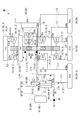
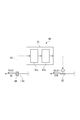
- FIG. 1 is a system diagram showing an outline of a boost system according to a first embodiment of the present invention.
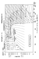
- FIG. 5 is a Ph diagram showing the state of carbon dioxide in the boosting system according to the first embodiment. It is a principal part enlarged view which shows the structure of a temperature cooling part regarding the pressure
- FIG. 5 is a QH diagram showing a change in performance characteristics of the pump unit according to the state of the fluid introduced into the pump unit in the boosting system according to the first embodiment. It is a diagram showing the performance characteristic according to the IGV opening degree of a compression part, and the flow volume of the fluid introduce
- the pressurization system 1A is a system that boosts gaseous carbon dioxide F as a target gas to a pressure higher than a target pressure higher than the critical pressure.
- the pressurization system 1A includes a compression unit 2 that takes in carbon dioxide F and compresses it, and cools the intermediate supercritical fluid generated in the compression unit 2 to near the critical temperature.
- generated by the cooling part to the pressure more than target pressure are provided.
- the pressure increasing system 1A includes a heating unit 5 that heats the carbon dioxide F that has been boosted by the pump unit 4, and a vacuum extraction unit 6 that is provided between the cooling unit 3 and the pump unit 4 to extract the carbon dioxide F.
- the pressure increasing system 1A includes a pressure detector 8A that detects the pressure (inlet pressure) P1 of the carbon dioxide F on the inlet side of the pump unit 4 and the pressure (outlet pressure) P2 of the carbon dioxide F on the outlet side, and a pressure A cooling temperature adjustment unit 9A that adjusts the flow rate of carbon dioxide F taken out by the extractor decompression unit 6 based on the pressure value of the carbon dioxide F detected by the detection unit 8A.
- the pressurizing system 1A of the present embodiment is characterized in that the cooling temperature adjusting unit 9A adjusts the flow rate of the carbon dioxide F based on the inlet pressure P1 and the outlet pressure P2 detected by the pressure detecting unit 8A.
- the compression unit 2 constitutes the first compression unit of the present invention, and is composed of a multi-shaft multi-stage geared compressor in which a plurality of impellers are linked via gears.
- the compression unit 2 includes a plurality of intercoolers provided one by one between a plurality of impellers 10 provided in multiple stages (six stages in the present embodiment), and between the adjacent impellers 10 and the cooling unit 3. 20. Then, the compression unit 2 generates the intermediate supercritical fluid F1 by compressing the captured carbon dioxide F as the introduced gas F0 to a pressure state of an intermediate pressure that is equal to or higher than the critical pressure and repeatedly lower than the target pressure while repeating compression and cooling. To do.
- the critical pressure of the carbon dioxide F is 7.4 [MPa], and as the target pressure, for example, 15 [MPa] is set as a value higher than the critical pressure. Further, as the intermediate pressure of the intermediate supercritical fluid F1 generated in the compression unit 2, for example, 10 [MPa] is set. However, the values of the target pressure and the intermediate pressure are appropriately determined according to the critical pressure of the target gas, and do not limit the present invention.
- paragraph compression impeller 12 which were provided in order toward the downstream from the upstream side into which carbon dioxide F is taken in and distribute
- the elements of the compression unit 2 are connected to each other by pipes L1, L2, L3, L4, L5, L6, L7, L8, L9, L10, and L11.
- the cooling unit 3 is connected to the downstream side of the sixth intermediate cooler 26 by a pipe L12, and cools the intermediate supercritical fluid F1 generated from the six-stage compression impeller 16 serving as the final stage of the compression unit 2 to near the critical temperature. Then, it is liquefied to generate an intermediate supercritical pressure liquid F2.
- the cooling unit 3 includes a pre-cooling unit 33 that pre-cools the intermediate supercritical fluid F1 generated by the compression unit 2, and further cools the intermediate supercritical fluid F1 that has been cooled by the pre-cooling unit 33 to generate an intermediate supercritical pressure. And a main cooling unit 31 that generates the liquid F2.
- the pre-cooling unit 33 is a heat exchanger that pre-cools the intermediate supercritical fluid F1 with an external cooling medium W supplied from a pipe line (not shown).
- the main cooling unit 31 introduces the low-temperature liquid F5 from the extraction decompression unit 6 described later, and cools the intermediate supercritical fluid F1 using this as a cooling medium.
- this embodiment performs the heating in the heating part 5 with the heat
- the main cooling unit 31 uses the low-temperature liquid F5 from the extraction / decompression unit 6 as a cooling medium.
- the pre-cooling unit 33 performs pre-cooling. By doing so, it becomes possible to reduce the amount of cold heat required in the main cooling section 31.
- the cooling capacity of the precooling unit 33 varies depending on the temperature and flow rate of the external cooling medium W taken in from the outside by the precooling unit 33.
- the intermediate supercritical fluid F1 generated in the compression unit 2 is cooled to the liquid transition region only by the sixth intermediate cooler 26, and then liquefied by the main cooling unit 31 to generate the intermediate supercritical pressure liquid F2. If possible, the precooling section 33 can be omitted.
- the intermediate supercritical fluid F1 when cooled to near the critical temperature in the cooling unit 3, it is preferably cooled to a temperature that is ⁇ 20 [° C.] of the critical temperature, and more preferably ⁇ 15 [° C.] of the critical temperature. Most preferably, it is cooled to a temperature that becomes ⁇ 10 [° C.] of the critical temperature.
- the pump unit 4 forms the second compression unit of the present invention, is connected to the downstream side of the cooling unit 3 by a pipe L13, and introduces an intermediate supercritical pressure liquid F2 generated through the cooling unit 3 Then, the pressure is increased to the target pressure state to generate the target pressure liquid F3.
- the pump unit 4 employs a two-stage configuration including a single-stage pump impeller 41 and a two-stage pump impeller 43.
- the configuration is Is optional.
- the first pressure sensor 81 is provided in the pipe line L13.
- the heating unit 5 is connected to the downstream side of the pump unit 4 by a pipe L14, introduces a target pressure liquid F3 from the pump unit 4, and a target supercritical fluid F4 having a critical temperature (31.1 [° C.]) or higher. Is generated.
- the heating unit 5 constitutes a heat exchanger together with the main cooling unit 31 of the cooling unit 3. Therefore, in this heating part 5, by performing heat exchange with the main cooling part 31, the target pressure liquid F3 is heated by the condensation heat obtained by cooling the intermediate supercritical fluid F1 in the main cooling part 31.
- a second pressure sensor 83 is provided in the pipe line L14.
- a pipe line L15 is connected to the downstream side of the heating unit 5.
- the target supercritical fluid F4 generated in the heating unit 5 flows into the pipe L15 and is supplied to external equipment connected to the downstream side.
- the extraction liquid decompression unit 6 is provided between the main cooling unit 31 and the pump unit 4, and the main cooling unit is obtained by the low temperature liquid F5 obtained by extracting a part of the intermediate supercritical pressure liquid F2 from the main cooling unit 31.
- the intermediate supercritical fluid F1 at 31 is cooled. Along with this cooling, the low temperature liquid F5 itself is heated.
- the extraction liquid decompression unit 6 has a branch line 61 having one end connected to the line L13 so as to branch from the line L13 between the main cooling unit 31 and the pump unit 4, and this The other end of the branch pipe 61 is connected, and a heat exchanging unit 62 that exchanges heat with the main cooling unit 31 is provided.
- a flow rate adjusting unit 92 is provided in the middle of the branch pipe 61.
- the flow rate adjusting unit 92 is composed of a valve capable of adjusting the opening degree, and for example, a flow rate adjusting valve is employed.
- bypass channel 7 The bypass flow path 7 returns the low-temperature liquid F5 from the extraction decompression unit 6 to the upstream side of the six-stage compression impeller 16 of the compression unit 2.
- One end of the bypass channel 7 is connected to the heat exchanging unit 62 of the extract decompression unit 6, and the other end is connected to the pipe line L ⁇ b> 10 between the six-stage compression impeller 16 and the fifth intermediate cooler 25. .
- the pressure detection unit 8A includes a first pressure sensor 81 provided in the middle of the pipe line L13 and a second pressure sensor 83 provided in the middle of the pipe line L14.
- the first pressure sensor 81 measures the pressure value of the intermediate supercritical pressure liquid F2 flowing through the line L13, that is, the inlet pressure P1 of the pump unit 4, and the second pressure sensor 83 is the target pressure liquid F3 flowing through the line L14. , That is, the outlet pressure P2 of the pump unit 4 is measured.
- the inlet pressure P1 and the outlet pressure P2 measured by the pressure detection unit 8A are transmitted to the control unit 91 of the cooling temperature adjustment unit 9A described later.
- the cooling temperature adjustment unit 9 ⁇ / b> A includes a control unit 91 electrically connected to the pressure detection unit 8 ⁇ / b> A and a flow rate adjustment unit 92 electrically connected to the control unit 91 through a control signal line 93.
- the flow rate adjusting unit 92 depressurizes the intermediate supercritical pressure liquid F2 extracted by adjusting the opening degree by the Joule-Thompson effect to generate the low temperature liquid F5.
- the opening degree of the flow rate adjusting unit 92 is adjusted by the control unit 91.
- the control unit 91 includes a determination unit 91a connected to the pressure detection unit 8A and a flow rate determination unit 91b connected to the determination unit 91a.
- the determination unit 91a is electrically connected to the pressure detection unit 8A, and whether or not the inlet pressure P1 and the outlet pressure P2, which are detection values detected by the pressure detection unit 8A, match a predetermined determination value Ps.
- the determination process is performed.
- This determination value Ps is a numerical range including the target pressure of the target supercritical fluid F4 generated by the pressure increasing system 1A, and is input to the determination unit 91a via an input unit (not shown). Memorized and retained.
- the deviation ⁇ P which is the determination result by the determination unit 91a, is transmitted to the flow rate determination unit 91b.
- the pressure difference P2-1 is P2-P1, it may be P1-P2.
- the flow rate determination unit 91b performs a predetermined calculation based on the deviation ⁇ P acquired from the determination unit 91a, and calculates the opening degree of the flow rate adjustment unit 92. More specifically, first, a pressure value deviation ⁇ P and a flow rate increase / decrease amount necessary to eliminate the deviation ⁇ P are derived from a predetermined relational expression. This relational expression is obtained empirically by the performance requirements of the boost system 1A.
- the flow rate determining unit 91b calculates the opening degree of the flow rate adjusting unit 92 based on the increase / decrease amount of the flow rate derived by this relational expression.
- the relationship between the increase / decrease amount of the flow rate and the opening degree of the flow rate adjustment unit 92 is determined by the performance requirements of the flow rate adjustment valve used in the flow rate adjustment unit 92.
- the flow rate determining unit 91b transmits instruction information related to the increase / decrease of the determined opening degree to the flow rate adjusting unit 92.
- the flow rate adjustment unit 92 (flow rate adjustment valve) that has acquired the instruction information from the flow rate determination unit 91b adjusts the opening according to the instruction information.
- the control using the pressure difference P 2-1 has been described here, the control can also be performed using the pressure ratio P 2/1 .
- the intermediate supercritical fluid F1 in the state S7b is introduced into the precooling section 33 (state S7c).
- the intermediate supercritical fluid F1 can be cooled by being further cooled in an isobaric state (cooling step).
- This intermediate supercritical fluid F1 is cooled at the same pressure by the main cooling unit 31 while maintaining the supercritical pressure, and becomes a state S8a below the critical temperature, so that the intermediate supercritical fluid F1 changes to the intermediate supercritical pressure liquid F2. And it introduce
- the intermediate supercritical pressure liquid F2 in the state S8a is boosted to a target pressure that can be stored in the ground or on the seabed, and the temperature rises so that the target pressure liquid F3 in the state S8b. (Pump process). Thereafter, the target pressure liquid F3 is heated by the heating unit 5 to raise the temperature at an equal pressure to a critical temperature or higher, and the final state S9 in which the carbon dioxide F can be stored in the ground or on the seabed. To do.
- a part of the intermediate supercritical pressure liquid F2 that has entered the state S8a in the main cooling unit 31 is extracted by adjusting the opening degree of the flow rate adjusting unit 92 of the cooling temperature adjusting unit 9A.
- the amount of the intermediate supercritical pressure liquid F2 extracted is adjusted according to the opening degree of the flow rate adjusting unit 92.
- the extracted intermediate supercritical pressure liquid F2 is depressurized to become the low temperature liquid F5 in the state S10.
- the pressure of the low temperature liquid F5 in this state S10 is a pressure corresponding to the pressure upstream of the six-stage compression impeller 16 and downstream of the fifth intermediate cooler 25.
- the low-temperature liquid F5 is heated by exchanging heat with the cooling unit 3 and is vaporized while being in an isobaric state, and becomes a gas in the state S6a on the upstream side of the six-stage compression impeller 16 or a supercritical fluid.
- This gas or supercritical fluid is returned to the upstream side of the six-stage compression impeller 16 by the bypass flow path 7 and mixed into the intermediate supercritical fluid F1 flowing through the compression section 2.
- the pressure increasing system 1A controls the opening degree of the flow rate adjusting unit 92 so that the deviation ⁇ P (P2 ⁇ P1) between the inlet pressure P1 and the outlet pressure P2 of the pump unit 4 is constant. That is, the pressure increasing system 1A adjusts the flow rate adjusting unit 92 based on the deviation ⁇ P in which both the inlet pressure P1 and the outlet pressure P2 are taken into account, so the flow rate adjusting unit 92 is adjusted based only on the outlet pressure P2. It is difficult for control interference to occur.
- valve mechanism Inlet Guide Vane
- the rotation speed of the compression unit 2 is adjusted to control the inlet pressure P1 to be constant, this control and the control by the deviation ⁇ P are responsive. Since the characteristics are different, interference between the two can be prevented. If the inlet pressure P1 is controlled to be constant, the final discharge pressure can also be controlled to be constant according to this embodiment.
- the booster system 1A if the same impeller as that of the compression unit 2 is applied to a portion on the rear stage that is at a high pressure, a large number of high-pressure gas seals and high-pressure compressor casings are required. .
- the boosting system 1A employs the pump unit 4 on the high pressure side. Since the pump unit 4 pressurizes the liquid, it is easy to seal the target fluid when the pressure is increased to a high pressure state (about 15 to 60 [MPa]), so that an increase in cost can be avoided.
- FIG. 4 is a QH diagram showing the relationship between the deviation (lift) between the inlet pressure P1 and the outlet pressure P2 of the pump unit 4 and the flow rate.
- the QH curve of the intermediate supercritical fluid F2 in the state S8x has a lower head as a whole than the QH curve of the intermediate supercritical fluid F2 in the state S8a. That is, as the temperature of the intermediate supercritical pressure liquid F2 increases and the density decreases, the pressure of the target pressure liquid F3 generated by the pump unit 4 decreases and becomes the state S8y in FIG.
- the target pressure liquid F3 in the state S8y is introduced into the heating unit 5 and heated in an isobaric state to become the target supercritical fluid F4 in the state S9x.
- the pressure of the target supercritical fluid F4 finally obtained without changing the pump rotational speed or the like of the pump unit 4 is obtained. (Target pressure) can be adjusted.
- the pressure of the finally obtained target supercritical fluid F4 can be adjusted to a constant target pressure. Therefore, the target pressure can be obtained without providing the pump unit 4 with, for example, a variable speed motor.
- the pressure of the target supercritical fluid F4 is detected at any time by the pressure detector 8A provided in the middle of the pipe line L13 and the pipe line L14.
- the detected pressure values (inlet pressure P1 and outlet pressure P2) are input to the control unit 91 of the cooling temperature adjustment unit 9A.
- the control part 91 determines the opening degree of the flow volume adjustment part 92 through a predetermined calculation, and performs the adjustment.
- the above-described operation is autonomously executed by the cooling temperature adjustment unit 9A and the pressure detection unit 8A.
- the opening degree of the flow rate adjusting unit 92 is autonomously adjusted according to the change, and the target supercritical fluid F4 The pressure is corrected towards a predetermined desired target pressure. Thereby, the pressure of the target supercritical fluid F4 can be supplied in a stabilized state.
- the low-temperature liquid F5 from the extraction / decompression unit 6 is used as the cooling medium of the main cooling unit 31.
- the pre-cooling unit 33 preliminarily By cooling, the amount of cold heat required in the main cooling unit 31 can be reduced. For example, in this case, the cooling from the state S7b to the state S7c is cooled by the pre-cooling unit 33, and the cooling from the state S7c to the state S8a is performed by the main cooling unit 31.
- an IGV not shown is adopted as a means for adjusting the flow rate of the introduced gas F0 introduced into the compression unit 2.
- the IGV is a throttle valve that is provided in the middle of the pipe and can adjust the opening. As the opening degree of the IGV becomes smaller, the flow rate of the introduced gas F0 introduced into the compression unit 2 can be reduced.
- the IGV is preferably provided at the introduction portion of the one-stage compression impeller 11.
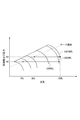
- FIG. 5 is a diagram showing performance characteristics according to changes in the IGV opening of the compression unit 2.
- the flow rate of the fluid introduced into the compression unit 2 decreases as the IGV opening decreases from 100%, which is in the fully open state, to 90% and 80%.
- the higher the discharge pressure of the compression unit 2 the higher the value of the critical flow rate that reaches the surge limit.
- two operation states of a discharge pressure H3 and a discharge pressure H4 lower than the discharge pressure H3 are shown.
- the discharge pressure H3 the surge limit is reached at a flow rate of 80%, but in the case of the discharge pressure H4, the flow rate reaching the surge limit is expanded to 70%.
- the discharge pressure of the compression unit 2 that is, the intermediate amount generated in the compression unit 2.
- the pressure of the supercritical fluid F1 can be reduced.
- the allowable flow range (operating range) can be expanded as the discharge pressure is lowered by reducing the opening of the IGV.
- the pressure range of the target supercritical fluid F4 obtained by the pressure increasing system 1A can be widened.
- a booster system 1B according to a second embodiment of the present invention will be described with reference to FIGS.
- the boosting system 1B is different from the part detected by the pressure detection unit 8B, and the boosting system 1A of the first embodiment is different except that the opening degree control method by the flow rate adjustment unit 92 of the cooling temperature adjustment unit 9B is different.
- the basic configuration is the same. Therefore, hereinafter, this difference will be mainly described.
- the booster system 1 ⁇ / b> B has a pressure detector 8 ⁇ / b> B in the middle of the pipe line L ⁇ b> 15.
- the pressure detector 8B measures an outlet pressure P2 that is a pressure value of the target supercritical fluid F4 flowing through the pipe line L15.
- the outlet pressure P2 measured by the pressure detection unit 8B is transmitted to the control unit 91 of the cooling temperature adjustment unit 9B.
- the cooling temperature adjustment unit 9B includes a control unit 91 and a flow rate adjustment unit 92, similar to the cooling temperature adjustment unit 9A, and the flow rate adjustment unit 92 generates the low-temperature liquid F5 in the same manner as in the first embodiment. .
- the control unit 91 includes a determination unit 91a and a flow rate determination unit 91b. However, as described below, the determination content of the determination unit 91a is different from that of the first embodiment.
- the determination unit 91a transmits a deviation ⁇ P that is a determination result to the flow rate determination unit 91b.
- the determination unit 91a has a dead zone DB for determination, and if the outlet pressure P2 exceeds the range of the dead zone DB, the determination unit 91a transmits a deviation ⁇ P as a determination result to the flow rate determination unit 91b. When it falls within the range of the dead zone DB, the deviation ⁇ P is not transmitted to the flow rate determining unit 91b.
- Information regarding the dead zone DB is stored in advance in the determination unit 91a. As shown in FIG. 8, the dead zone DB is set as a range sandwiched between a positive predetermined value PN and a negative predetermined value NN with reference to the determination value Ps.
- the determination unit 91a determines whether or not the outlet pressure P2 is equal to or lower than a predetermined value PN and equal to or higher than a negative predetermined value NN. For example, in the case of FIG. 8, the determination unit 91a does not transmit the deviation ⁇ P to the flow rate determination unit 91b in the periods T1 and T3, but transmits the deviation ⁇ P to the flow rate determination unit 91b in the period T2.
- the flow rate determination unit 91b calculates the opening degree of the flow rate adjustment unit 92 based on the acquired deviation ⁇ P, and transmits instruction information related to the increase / decrease of the opening degree to the flow rate adjustment unit 92, as in the first embodiment. .
- the flow rate adjustment unit 92 (flow rate adjustment valve) that has acquired the instruction information from the flow rate determination unit 91b adjusts the opening according to the instruction information.
- the dead zone DB is provided for the discharge pressure control, and the flow rate adjusting unit 92 is adjusted only when the outlet pressure P2 of the pump unit 4 is largely changed.
- the deviation ⁇ P is regarded as zero, and the previous flow rate is maintained without changing the opening degree of the flow rate adjusting unit 92.
- the outlet pressure P2 greatly deviates from the determination value Ps, the deviation ⁇ P is not zero, and at this time, the opening degree of the flow rate adjusting unit 92 is adjusted. By doing so, the time during which the control of the outlet pressure P2 and the control of the suction pressure of the pump unit 4 are simultaneously performed is shortened, so that interference between the two can be prevented.
- the configuration described in the above embodiment can be selected or changed to another configuration as appropriate.
- a geared compressor is used for the compression unit 2
- the compressor used for the compression unit 2 is not limited to a geared compressor, and other types of compressors are employed. May be.
Landscapes
- Engineering & Computer Science (AREA)
- Mechanical Engineering (AREA)
- General Engineering & Computer Science (AREA)
- Physics & Mathematics (AREA)
- Thermal Sciences (AREA)
- Chemical & Material Sciences (AREA)
- Chemical Kinetics & Catalysis (AREA)
- Structures Of Non-Positive Displacement Pumps (AREA)
- Control Of Positive-Displacement Air Blowers (AREA)
- Control Of Positive-Displacement Pumps (AREA)
- Separation By Low-Temperature Treatments (AREA)
Abstract
本発明の昇圧システム1Aは、ポンプ部4の上流において主冷却部31で冷却、生成された中間超臨界圧液体の温度を、供給する冷却媒体の流量によって調整する冷却温度調整部9Aと、ポンプ部4の入口側において中間超臨界圧液体の入口圧力P1を検出するとともに、ポンプ部4の出口側において目標超臨界流体の出口圧力P2を検出する圧力検出部と、を備える。冷却温度調整部9Aは、入口圧力P1と出口圧力P2の圧力差、又は、入口圧力P1と出口圧力P2の圧力比、に基づいて、冷却媒体の流量を制御することを特徴とする。
Description
本発明は、気体の昇圧を行う昇圧システムに関する。
昇圧システムは、対象となる気体を目標圧力まで昇圧する装置であり、昇圧システムを利用して二酸化炭素を昇圧して液化させ、陸上又は海底の地中へ貯留することで大気中の二酸化炭素を低減する技術が検討されている。近年、温室効果ガスとして知られる二酸化炭素の排出量増大によって地球温暖化等の問題が顕在化してきており、例えば火力発電所の排気ガスに含まれる二酸化炭素を分離・回収した後に、昇圧システムによって昇圧することが検討されている。
この昇圧システムにおいては、多段に構成された圧縮機によって段階的に二酸化炭素の圧縮を行い、超臨界圧力・温度以上の状態となった二酸化炭素を冷却することで、輸送・貯留に最適な目標温度・圧力の二酸化炭素を得ている。この昇圧システムとしては、特許文献1及び特許文献2に開示されたシステムが知られている。
特許文献1及び特許文献2に開示された昇圧システムは、主たる要素として圧縮部と、冷却部と、ポンプ部とを備える。圧縮部は、臨界圧以上、目標圧未満の中間圧まで対象気体を圧縮して中間超臨界流体を生成する。冷却部は、圧縮部で生成された中間超臨界流体を臨界温度近傍まで冷却して中間超臨界圧液体を生成する。また、ポンプ部は、冷却部で生成された中間超臨界圧液体を目標圧以上の圧力まで昇圧する。冷却部は、圧縮部で生成された中間超臨界流体の一部を抽液して冷却媒体として用いる。
特許文献2は、ポンプ部の上流に冷却温度調整部を設けることで、冷却部で生成される中間超臨界圧液体の温度を調整する。こうして、特許文献2は、ポンプ部のポンプ回転数が一定の状態であっても、冷却部で生成される中間超臨界圧液体の温度を調整することで、最終的に生成される目標超臨界流体の圧力を調整することができる。より具体的には、特許文献2は、ポンプ部よりも下流側に設けられる加熱部によって加熱された二酸化炭素の圧力を検出する圧力検出部と、冷却部へ供給する冷却媒体(中間超臨界流体)の量を調整する流量調整弁と、を設け、圧力検出部で検出された検出値と所定の圧力範囲との偏差に基づいて、流量調整弁の開度を調整する。こうすることで、特許文献2は、冷却部で生成され、ポンプ部に吸入される中間超臨界圧液体の温度(ポンプ入口温度)を調整する。なお、特許文献2において、加熱部によって加熱された二酸化炭素の圧力は、昇圧システムの最終吐出圧力である。
特許文献2は、ポンプ部の上流に冷却温度調整部を設けることで、冷却部で生成される中間超臨界圧液体の温度を調整する。こうして、特許文献2は、ポンプ部のポンプ回転数が一定の状態であっても、冷却部で生成される中間超臨界圧液体の温度を調整することで、最終的に生成される目標超臨界流体の圧力を調整することができる。より具体的には、特許文献2は、ポンプ部よりも下流側に設けられる加熱部によって加熱された二酸化炭素の圧力を検出する圧力検出部と、冷却部へ供給する冷却媒体(中間超臨界流体)の量を調整する流量調整弁と、を設け、圧力検出部で検出された検出値と所定の圧力範囲との偏差に基づいて、流量調整弁の開度を調整する。こうすることで、特許文献2は、冷却部で生成され、ポンプ部に吸入される中間超臨界圧液体の温度(ポンプ入口温度)を調整する。なお、特許文献2において、加熱部によって加熱された二酸化炭素の圧力は、昇圧システムの最終吐出圧力である。
以上の昇圧システムにおいて、定格運転点よりも二酸化炭素の流量が少ない部分負荷による運転が行われることがある。この部分負荷運転をする場合においても、昇圧システムの最終吐出圧力を一定に維持することが求められる。
ところが、特許文献2に開示される制御方法にしたがって冷却部へ供給する冷却媒体の量を調整すると、ポンプ部へ向かう中間超臨界流体の量が変化するために、ポンプ部の入口側の二酸化炭素の温度(ポンプ入口温度)だけでなくポンプ部の入口側の二酸化炭素の圧力(ポンプ入口圧力)も変化してしまう。密度は温度及び圧力の両方の影響を受けて変化するために、圧力変化による制御動作が加わってしまい、流量調整弁が想定している制御動作と異なる動きをすることが懸念される。例えば、ポンプ部の出口側の圧力(ポンプ出口圧力)、つまり最終吐出圧力が所定の圧力範囲よりも高い場合には、流量調整弁の開度を小さくして、冷却部への冷却媒体の流量を絞り、ポンプ入口温度を高くすることになる。そうすると、ポンプ出口圧力に基づく流量調整弁の制御においては、ポンプ部へ向かう中間超臨界流体の量が増えるために、ポンプ入口圧力が高くなるので、ポンプ出口圧力を低くしたいという要求と干渉してしまい、本来予定されていたポンプ入口温度の変化による二酸化炭素の密度調整ができなくなることがある。
また、例えば、圧縮部の動作を制御することによりポンプ入口圧力を一定に制御できるが、この制御とポンプ出口圧力(最終吐出圧力)の制御とが干渉してしまい、安定した運転ができなくなる。
ところが、特許文献2に開示される制御方法にしたがって冷却部へ供給する冷却媒体の量を調整すると、ポンプ部へ向かう中間超臨界流体の量が変化するために、ポンプ部の入口側の二酸化炭素の温度(ポンプ入口温度)だけでなくポンプ部の入口側の二酸化炭素の圧力(ポンプ入口圧力)も変化してしまう。密度は温度及び圧力の両方の影響を受けて変化するために、圧力変化による制御動作が加わってしまい、流量調整弁が想定している制御動作と異なる動きをすることが懸念される。例えば、ポンプ部の出口側の圧力(ポンプ出口圧力)、つまり最終吐出圧力が所定の圧力範囲よりも高い場合には、流量調整弁の開度を小さくして、冷却部への冷却媒体の流量を絞り、ポンプ入口温度を高くすることになる。そうすると、ポンプ出口圧力に基づく流量調整弁の制御においては、ポンプ部へ向かう中間超臨界流体の量が増えるために、ポンプ入口圧力が高くなるので、ポンプ出口圧力を低くしたいという要求と干渉してしまい、本来予定されていたポンプ入口温度の変化による二酸化炭素の密度調整ができなくなることがある。
また、例えば、圧縮部の動作を制御することによりポンプ入口圧力を一定に制御できるが、この制御とポンプ出口圧力(最終吐出圧力)の制御とが干渉してしまい、安定した運転ができなくなる。
以上より、本発明は、運転の最中に部分負荷運転のように負荷が変動する場合にも、最終吐出圧力を安定して制御できる昇圧システムを提供することを目的とする。
本発明による昇圧システムは、対象気体を臨界圧より高い目標圧以上の圧力まで昇圧する昇圧システムであって、臨界圧以上、目標圧未満の中間圧まで対象気体を圧縮して中間超臨界流体を生成する第一圧縮部と、第一圧縮部で生成された中間超臨界流体を臨界温度近傍まで冷却して中間超臨界圧液体を生成する冷却部と、冷却部で生成された中間超臨界圧液体を目標圧以上の圧力まで昇圧する第二圧縮部と、第二圧縮部の上流にて冷却部で生成された中間超臨界圧液体の温度を、供給する冷却媒体の流量によって調整する冷却温度調整部と、第二圧縮部の入口側において中間超臨界圧液体の入口圧力P1を検出するとともに、第二圧縮部の出口側における目標超臨界流体の出口圧力P2を検出する圧力検出部と、を備える。
そして、本発明の第一態様による冷却温度調整部は、入口圧力P1と出口圧力P2の圧力差、又は、入口圧力P1と出口圧力P2の圧力比、が所定の範囲に収まるように、冷却媒体の流量を制御する、ことを特徴とする。
次に、本発明の第二態様に係る冷却温度調整部は、圧力検出部で検出される目標超臨界流体の出口圧力P2が、予め設定された判定値Psを基準にする不感帯の範囲を超える場合に、出口圧力P2と判定値Psとの偏差△Pに基づいて、冷却媒体の流量を増減させる。この、冷却温度調整部は、出口圧力P2が、不感帯の範囲にある場合には、冷却媒体の従前の流量を維持する。
本発明において、第二圧縮部は、単数又は複数のポンプからなることが好ましい。
この昇圧システムによれば、前段側での圧縮を圧縮部で行い、より高圧となっている後段側での中間超臨界流体の圧送による昇圧をポンプで行って目標圧以上の圧力の液体を得ることができる。高圧となっている第二圧縮部に圧縮機を適用できるが、高圧ガスシールや高圧に対応した圧縮機ケーシングが多数必要となる。後段側にポンプを採用すれば、これら高圧に対応する要素が不要となるためコスト低減や信頼性向上が可能となる。
この昇圧システムによれば、前段側での圧縮を圧縮部で行い、より高圧となっている後段側での中間超臨界流体の圧送による昇圧をポンプで行って目標圧以上の圧力の液体を得ることができる。高圧となっている第二圧縮部に圧縮機を適用できるが、高圧ガスシールや高圧に対応した圧縮機ケーシングが多数必要となる。後段側にポンプを採用すれば、これら高圧に対応する要素が不要となるためコスト低減や信頼性向上が可能となる。
本発明において、第二圧縮部で昇圧された中間超臨界圧液体を臨界温度近傍まで加熱して目標超臨界流体を生成する加熱部をさらに備えることができ、この場合、冷却部は、加熱部との間で熱交換を行って中間超臨界流体を冷却する主冷却部を備えることができる。
この昇圧システムによれば、第二圧縮部で生成された目標圧以上の圧力の液体を加熱部によって臨界温度近傍まで加熱することで目標とする圧力、温度の超臨界流体を得ることができる。
また、冷却部における主冷却部によって、中間超臨界流体の冷却の際に回収した熱を利用することで、より効率良く臨界温度近傍まで中間超臨界圧液体を加熱して目標とする圧力、温度の超臨界流体(目標超臨界流体)を得ることができる。
この昇圧システムによれば、第二圧縮部で生成された目標圧以上の圧力の液体を加熱部によって臨界温度近傍まで加熱することで目標とする圧力、温度の超臨界流体を得ることができる。
また、冷却部における主冷却部によって、中間超臨界流体の冷却の際に回収した熱を利用することで、より効率良く臨界温度近傍まで中間超臨界圧液体を加熱して目標とする圧力、温度の超臨界流体(目標超臨界流体)を得ることができる。
本発明において、冷却温度調整部は、第一圧縮部で生成された中間超臨界流体の一部を抽液して冷却媒体として用いることができる。
そうすれば、第二圧縮部へ導入される中間超臨界圧液体自身の冷熱を有効に利用することができるため、中間超臨界流体から中間超臨界圧液体を生成するために必要な凝縮器を別途設けることなく、第二圧縮部へ導入する中間超臨界圧液体を確実に生成できる。
そうすれば、第二圧縮部へ導入される中間超臨界圧液体自身の冷熱を有効に利用することができるため、中間超臨界流体から中間超臨界圧液体を生成するために必要な凝縮器を別途設けることなく、第二圧縮部へ導入する中間超臨界圧液体を確実に生成できる。
本発明において、冷却温度調整部は、冷却部へ供給する冷却媒体の流量を調整することができる。
このように、冷却媒体の流量を調整することで、冷却部で生成される中間超臨界流体の温度、圧力を所望の値に調整することができる。
このように、冷却媒体の流量を調整することで、冷却部で生成される中間超臨界流体の温度、圧力を所望の値に調整することができる。
本発明において、冷却温度調整部は、冷却部へ供給する冷却媒体の流量を調整する流量調整部と、圧力検出部が検出した検出値に基づいて流量調整部を制御する制御部とを有し、制御部は、検出値が予め定められた圧力範囲に属するか否かを判定する判定部と、判定部の判定結果に基づいて、流量調整部で調整する流量を決定する流量決定部と、を備えることができる。
このように構成することで、目標超臨界圧流体の圧力をより安定的に維持することができる。
このように構成することで、目標超臨界圧流体の圧力をより安定的に維持することができる。
本発明の第一態様に係る昇圧システムによれば、流量調整部の開度の調節を、第二圧縮部の入口圧力と出口圧力の圧力差が一定になるように制御する。つまり、本発明の昇圧システムは、入口圧力及び出口圧力の両者が考慮された圧力差に基づいて流量調整部を開度調節するので、出口圧力だけに基づいて流量調整部を調整する際に生じる制御の干渉が生じにくい。したがって、第一圧縮部の入口の弁機構又は第一圧縮部の回転数を調整して第二圧縮部の入口圧力を一定に制御する場合でも、この制御と圧力差による制御は応答性が異なるため、両者の干渉を防止できる。また、入口圧力を一定に制御していれば、最終吐出圧力も一定に制御できる。
また、本発明の第二態様に係る昇圧システムによれば、吐出圧力制御に不感帯を持たせ、出口圧力が大きく変化したときだけ流量調整部を調節するので、出口圧力の変化が小さいときには、流量調整部の開度を変化させずに従前の流量を維持する。出口圧力が判定値から大きくずれてきたときには、流量調整部の開度を調整する。こうすることにより、出口圧力の制御と第二圧縮部、典型的にはポンプの吸入圧力の制御が同時に作用する時間が短くなるので、両者の干渉を防止できる。
また、本発明の第二態様に係る昇圧システムによれば、吐出圧力制御に不感帯を持たせ、出口圧力が大きく変化したときだけ流量調整部を調節するので、出口圧力の変化が小さいときには、流量調整部の開度を変化させずに従前の流量を維持する。出口圧力が判定値から大きくずれてきたときには、流量調整部の開度を調整する。こうすることにより、出口圧力の制御と第二圧縮部、典型的にはポンプの吸入圧力の制御が同時に作用する時間が短くなるので、両者の干渉を防止できる。
〔第1実施形態〕
以下、本発明に係る昇圧システムの第1実施形態を、添付図面を参照して説明する。
本実施形態に係る昇圧システム1Aは、対象気体として気体状態の二酸化炭素Fを臨界圧より高い目標圧以上の圧力まで昇圧するシステムである。
以下、本発明に係る昇圧システムの第1実施形態を、添付図面を参照して説明する。
本実施形態に係る昇圧システム1Aは、対象気体として気体状態の二酸化炭素Fを臨界圧より高い目標圧以上の圧力まで昇圧するシステムである。
図1に示すように、昇圧システム1Aは、二酸化炭素Fを取り込んで圧縮する圧縮部2と、圧縮部2で生成された中間超臨界流体を臨界温度近傍まで冷却して中間超臨界圧液体を生成する冷却部3と、冷却部で生成された中間超臨界圧液体を目標圧以上の圧力まで昇圧するポンプ部4と、を備えている。
また、この昇圧システム1Aは、ポンプ部4で昇圧された二酸化炭素Fを加熱する加熱部5と、冷却部3とポンプ部4との間に設けられて二酸化炭素Fを取り出す抽液減圧部6と、抽液減圧部6からの二酸化炭素Fを圧縮部2に返送するバイパス流路7と、を備えている。
加えて、この昇圧システム1Aは、ポンプ部4の入口側の二酸化炭素Fの圧力(入口圧力)P1及び出口側の二酸化炭素Fの圧力(出口圧力)P2を検出する圧力検出部8Aと、圧力検出部8Aが検出した二酸化炭素Fの圧力値に基づいて抽液減圧部6によって取り出される二酸化炭素Fの流量を調整する冷却温度調整部9Aと、を備えている。
本実施形態の昇圧システム1Aは、圧力検出部8Aで検出した入口圧力P1及び出口圧力P2に基づいて冷却温度調整部9Aが二酸化炭素Fの流量を調整するところに特徴を有している。
以下、昇圧システム1Aの各構成要素を説明した後に、昇圧システム1Aの動作、昇圧システム1Aの作用及び効果の順で説明する。
また、この昇圧システム1Aは、ポンプ部4で昇圧された二酸化炭素Fを加熱する加熱部5と、冷却部3とポンプ部4との間に設けられて二酸化炭素Fを取り出す抽液減圧部6と、抽液減圧部6からの二酸化炭素Fを圧縮部2に返送するバイパス流路7と、を備えている。
加えて、この昇圧システム1Aは、ポンプ部4の入口側の二酸化炭素Fの圧力(入口圧力)P1及び出口側の二酸化炭素Fの圧力(出口圧力)P2を検出する圧力検出部8Aと、圧力検出部8Aが検出した二酸化炭素Fの圧力値に基づいて抽液減圧部6によって取り出される二酸化炭素Fの流量を調整する冷却温度調整部9Aと、を備えている。
本実施形態の昇圧システム1Aは、圧力検出部8Aで検出した入口圧力P1及び出口圧力P2に基づいて冷却温度調整部9Aが二酸化炭素Fの流量を調整するところに特徴を有している。
以下、昇圧システム1Aの各構成要素を説明した後に、昇圧システム1Aの動作、昇圧システム1Aの作用及び効果の順で説明する。
[圧縮部2]
圧縮部2は、本発明の第一圧縮部をなすものであり、複数のインペラを、歯車を介して連動させた多軸多段構成のギアド圧縮機から構成される。
圧縮部2は、多段(本実施形態では6段)に設けられた複数のインペラ10と、相前後するインペラ10の間及び冷却部3との間に一つずつ設けられた複数の中間冷却器20とを有する。そして、圧縮部2は、取り込んだ二酸化炭素Fを導入気体F0として圧縮と冷却を繰り返しながら臨界圧以上であって、目標圧未満の中間圧の圧力状態まで圧縮して中間超臨界流体F1を生成する。
二酸化炭素Fの臨界圧は7.4[MPa]であり、目標圧としては、当該臨界圧よりも高い値として、例えば15[MPa]が設定される。また、圧縮部2で生成される中間超臨界流体F1の中間圧としては、例えば10[MPa]が設定される。ただし、目標圧及び中間圧の値は、対象気体の臨界圧に応じて適宜決定されるものであって、本発明を限定するものでない。
圧縮部2は、本発明の第一圧縮部をなすものであり、複数のインペラを、歯車を介して連動させた多軸多段構成のギアド圧縮機から構成される。
圧縮部2は、多段(本実施形態では6段)に設けられた複数のインペラ10と、相前後するインペラ10の間及び冷却部3との間に一つずつ設けられた複数の中間冷却器20とを有する。そして、圧縮部2は、取り込んだ二酸化炭素Fを導入気体F0として圧縮と冷却を繰り返しながら臨界圧以上であって、目標圧未満の中間圧の圧力状態まで圧縮して中間超臨界流体F1を生成する。
二酸化炭素Fの臨界圧は7.4[MPa]であり、目標圧としては、当該臨界圧よりも高い値として、例えば15[MPa]が設定される。また、圧縮部2で生成される中間超臨界流体F1の中間圧としては、例えば10[MPa]が設定される。ただし、目標圧及び中間圧の値は、対象気体の臨界圧に応じて適宜決定されるものであって、本発明を限定するものでない。
ここで、圧縮部2においては、二酸化炭素Fが取り込まれて流通する上流側から下流側に向かって順に設けられた一段圧縮インペラ11と、第一中間冷却器21と、二段圧縮インペラ12と、第二中間冷却器22と、三段圧縮インペラ13と、第三中間冷却器23と、四段圧縮インペラ14と、第四中間冷却器24と、五段圧縮インペラ15と、第五中間冷却器25と、六段圧縮インペラ16と、第六中間冷却器26とによって構成される。そして、これらの圧縮部2の要素が管路L1、L2、L3、L4、L5、L6、L7、L8、L9、L10、L11によって互いに接続されている。
[冷却部3]
冷却部3は、第六中間冷却器26の下流側に管路L12によって接続され、圧縮部2の最終段となる六段圧縮インペラ16から生成された中間超臨界流体F1を臨界温度近傍まで冷却して液化し、中間超臨界圧液体F2を生成する。
この冷却部3は、圧縮部2で生成された中間超臨界流体F1を予冷却する予冷却部33と、予冷却部33で冷却された中間超臨界流体F1をさらに冷却して中間超臨界圧液体F2を生成する主冷却部31とを有している。
冷却部3は、第六中間冷却器26の下流側に管路L12によって接続され、圧縮部2の最終段となる六段圧縮インペラ16から生成された中間超臨界流体F1を臨界温度近傍まで冷却して液化し、中間超臨界圧液体F2を生成する。
この冷却部3は、圧縮部2で生成された中間超臨界流体F1を予冷却する予冷却部33と、予冷却部33で冷却された中間超臨界流体F1をさらに冷却して中間超臨界圧液体F2を生成する主冷却部31とを有している。
予冷却部33は、図示を省略する管路から供給される外部冷却媒体Wによって中間超臨界流体F1を予冷却する熱交換器である。
主冷却部31は、後述する抽液減圧部6からの低温液体F5を導入し、これを冷却媒体として中間超臨界流体F1を冷却する。そして、本実施形態は、主冷却部31で中間超臨界流体F1を冷却することで得られる熱により加熱部5での加熱を行うものであり、主冷却部31と加熱部5とが一つの熱交換器を構成している。
主冷却部31は、後述する抽液減圧部6からの低温液体F5を導入し、これを冷却媒体として中間超臨界流体F1を冷却する。そして、本実施形態は、主冷却部31で中間超臨界流体F1を冷却することで得られる熱により加熱部5での加熱を行うものであり、主冷却部31と加熱部5とが一つの熱交換器を構成している。
本実施形態においては、主冷却部31は、冷却媒体として抽液減圧部6からの低温液体F5を用いるが、外部より適当な冷却媒体Wが得られる場合には、予冷却部33によって予冷却することで、主冷却部31で必要となる冷熱量の低減が可能となる。予冷却部33の冷却能力は、予冷却部33が外部から取り込む外部冷却媒体Wの温度及び流量等によって異なる。
なお、圧縮部2で生成された中間超臨界流体F1を第六中間冷却器26のみで液体への遷移領域まで冷却し、その後、主冷却部31によって液化されて中間超臨界圧液体F2を生成できるのであれば、予冷却部33を省略できる。
なお、圧縮部2で生成された中間超臨界流体F1を第六中間冷却器26のみで液体への遷移領域まで冷却し、その後、主冷却部31によって液化されて中間超臨界圧液体F2を生成できるのであれば、予冷却部33を省略できる。
また、冷却部3で中間超臨界流体F1を臨界温度近傍まで冷却する際には、好ましくは臨界温度の±20[℃]となる温度まで冷却し、より好ましくは臨界温度の±15[℃]となる温度まで冷却し、臨界温度の±10[℃]となる温度まで冷却することが最も好ましい。
[ポンプ部4]
ポンプ部4は、本発明の第二圧縮部をなすものであり、冷却部3の下流側に管路L13によって接続され、冷却部3を通過して生成された中間超臨界圧液体F2を導入して目標圧の圧力状態まで昇圧し、目標圧液体F3を生成する。本実施形態では、このポンプ部4は、一段ポンプインペラ41及び二段ポンプインペラ43からなる二段構成を採用しているが、中間超臨界圧液体F2を目標圧まで昇圧できる限り、その構成は任意である。
前述したように、管路L13には、第一圧力センサ81が設けられている。
ポンプ部4は、本発明の第二圧縮部をなすものであり、冷却部3の下流側に管路L13によって接続され、冷却部3を通過して生成された中間超臨界圧液体F2を導入して目標圧の圧力状態まで昇圧し、目標圧液体F3を生成する。本実施形態では、このポンプ部4は、一段ポンプインペラ41及び二段ポンプインペラ43からなる二段構成を採用しているが、中間超臨界圧液体F2を目標圧まで昇圧できる限り、その構成は任意である。
前述したように、管路L13には、第一圧力センサ81が設けられている。
[加熱部5]
加熱部5は、ポンプ部4の下流側に管路L14によって接続され、ポンプ部4からの目標圧液体F3を導入して、臨界温度(31.1[℃])以上の目標超臨界流体F4を生成する。
上述したように、加熱部5は、冷却部3の主冷却部31とともに熱交換器を構成している。したがって、この加熱部5では、主冷却部31との間で熱交換を行うことにより、主冷却部31で中間超臨界流体F1を冷却して得た凝縮熱によって目標圧液体F3を加熱する。
管路L14には、第二圧力センサ83が設けられている。
加熱部5は、ポンプ部4の下流側に管路L14によって接続され、ポンプ部4からの目標圧液体F3を導入して、臨界温度(31.1[℃])以上の目標超臨界流体F4を生成する。
上述したように、加熱部5は、冷却部3の主冷却部31とともに熱交換器を構成している。したがって、この加熱部5では、主冷却部31との間で熱交換を行うことにより、主冷却部31で中間超臨界流体F1を冷却して得た凝縮熱によって目標圧液体F3を加熱する。
管路L14には、第二圧力センサ83が設けられている。
さらに、加熱部5の下流側には、管路L15が接続されている。管路L15には、加熱部5にて生成された目標超臨界流体F4が流入し、下流側に接続された外部設備に供給される。
[抽液減圧部6]
抽液減圧部6は、主冷却部31とポンプ部4との間に設けられ、主冷却部31からの中間超臨界圧液体F2の一部を抽出して得た低温液体F5によって主冷却部31における中間超臨界流体F1の冷却を行う。この冷却に伴って、低温液体F5は自身が加熱される。
具体的にはこの抽液減圧部6は、主冷却部31とポンプ部4との間の管路L13から分岐するように、一端がこの管路L13に接続された分岐管路61と、この分岐管路61の他端が接続されて主冷却部31との間で熱交換を行う熱交換部62と、を有している。さらに、分岐管路61の中途位置には、流量調整部92が設けられている。流量調整部92は、その開度を調節することが可能な弁から構成され、例えば流量調節弁が採用される。
抽液減圧部6は、主冷却部31とポンプ部4との間に設けられ、主冷却部31からの中間超臨界圧液体F2の一部を抽出して得た低温液体F5によって主冷却部31における中間超臨界流体F1の冷却を行う。この冷却に伴って、低温液体F5は自身が加熱される。
具体的にはこの抽液減圧部6は、主冷却部31とポンプ部4との間の管路L13から分岐するように、一端がこの管路L13に接続された分岐管路61と、この分岐管路61の他端が接続されて主冷却部31との間で熱交換を行う熱交換部62と、を有している。さらに、分岐管路61の中途位置には、流量調整部92が設けられている。流量調整部92は、その開度を調節することが可能な弁から構成され、例えば流量調節弁が採用される。
[バイパス流路7]
バイパス流路7は、抽液減圧部6からの低温液体F5を圧縮部2の六段圧縮インペラ16の上流側に戻す。このバイパス流路7は、一端が抽液減圧部6の熱交換部62に接続され、他端が六段圧縮インペラ16と第五中間冷却器25との間の管路L10に接続されている。
バイパス流路7は、抽液減圧部6からの低温液体F5を圧縮部2の六段圧縮インペラ16の上流側に戻す。このバイパス流路7は、一端が抽液減圧部6の熱交換部62に接続され、他端が六段圧縮インペラ16と第五中間冷却器25との間の管路L10に接続されている。
[圧力検出部8A]
圧力検出部8Aは、管路L13の途中に設けられる第一圧力センサ81と、管路L14の途中に設けられる第二圧力センサ83と、を有している。第一圧力センサ81は、管路L13を流れる中間超臨界圧液体F2の圧力値、つまりポンプ部4の入口圧力P1を計測し、第二圧力センサ83は、管路L14を流れる目標圧液体F3の圧力値、つまりポンプ部4の出口圧力P2を計測する。
圧力検出部8Aで計測された入口圧力P1及び出口圧力P2は、後述する冷却温度調整部9Aの制御部91に送信される。
圧力検出部8Aは、管路L13の途中に設けられる第一圧力センサ81と、管路L14の途中に設けられる第二圧力センサ83と、を有している。第一圧力センサ81は、管路L13を流れる中間超臨界圧液体F2の圧力値、つまりポンプ部4の入口圧力P1を計測し、第二圧力センサ83は、管路L14を流れる目標圧液体F3の圧力値、つまりポンプ部4の出口圧力P2を計測する。
圧力検出部8Aで計測された入口圧力P1及び出口圧力P2は、後述する冷却温度調整部9Aの制御部91に送信される。
[冷却温度調整部9A]
冷却温度調整部9Aは、圧力検出部8Aに電気的に接続された制御部91と、制御信号線93によって制御部91と電気的に接続された流量調整部92と、を有している。
流量調整部92は、開度を調節することによって抽液した中間超臨界圧液体F2に対してジュールトムソン効果による減圧を行い、低温液体F5を生成する。流量調整部92の開度は、制御部91によって調節される。
冷却温度調整部9Aは、圧力検出部8Aに電気的に接続された制御部91と、制御信号線93によって制御部91と電気的に接続された流量調整部92と、を有している。
流量調整部92は、開度を調節することによって抽液した中間超臨界圧液体F2に対してジュールトムソン効果による減圧を行い、低温液体F5を生成する。流量調整部92の開度は、制御部91によって調節される。
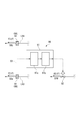
制御部91は、例えば図3に示すように、圧力検出部8Aに接続される判定部91aと、判定部91aに接続される流量決定部91bと、を有している。
判定部91aは、圧力検出部8Aに電気的に接続されるとともに、圧力検出部8Aが検出した検出値である入口圧力P1及び出口圧力P2が予め設定された判定値Psに合致するか否かの判定処理を行う。この判定値Psは、昇圧システム1Aによって生成される目標超臨界流体F4の目標圧を含む数値範囲であって、図示を省略する入力手段を介して判定部91aに入力され、判定部91aにて記憶、保持される。
判定部91aは、圧力検出部8Aに電気的に接続されるとともに、圧力検出部8Aが検出した検出値である入口圧力P1及び出口圧力P2が予め設定された判定値Psに合致するか否かの判定処理を行う。この判定値Psは、昇圧システム1Aによって生成される目標超臨界流体F4の目標圧を含む数値範囲であって、図示を省略する入力手段を介して判定部91aに入力され、判定部91aにて記憶、保持される。
判定部91aは、入口圧力P1と出口圧力P2の圧力差P2-1=P2-P1を算出し、この圧力差△Pと記憶された判定値Psとを比較して、圧力差P2-1と判定値Psとの偏差△Pを算出する。判定部91aによる判定結果である偏差△Pは、流量決定部91bに伝達される。なお、圧力差P2-1をP2-P1としたが、P1-P2としてもよい。
流量決定部91bは、判定部91aから取得した偏差△Pに基づいて所定の演算を行い、流量調整部92の開度を算出する。より詳細には、まず、圧力値の偏差△Pと、その偏差△Pを解消するために必要となる流量の増減量を所定の関係式から導出する。なお、この関係式は昇圧システム1Aの性能要件等によって経験的に求められるものである。
流量決定部91bは、この関係式によって導出された流量の増減量に基づいて、流量調整部92の開度を算出する。なお、流量の増減量と、流量調整部92の開度との関係は、流量調整部92に用いられる流量調整弁の性能要件等によって決定されるものである。
流量決定部91bは決定された開度の増減に係る指示情報を流量調整部92に伝達する。流量決定部91bからの指示情報を取得した流量調整部92(流量調節弁)はその指示情報に従って開度を調整する。
以上のとおりであり、制御部91は、P2-1=P2-P1が判定値Psと一致するように流量調整部92の開度、つまり中間超臨界圧液体F2の流量を制御する。
なお、ここでは圧力差P2-1を用いる制御を説明したが、圧力比P2/1を用いて制御することもできる。
流量決定部91bは決定された開度の増減に係る指示情報を流量調整部92に伝達する。流量決定部91bからの指示情報を取得した流量調整部92(流量調節弁)はその指示情報に従って開度を調整する。
以上のとおりであり、制御部91は、P2-1=P2-P1が判定値Psと一致するように流量調整部92の開度、つまり中間超臨界圧液体F2の流量を制御する。
なお、ここでは圧力差P2-1を用いる制御を説明したが、圧力比P2/1を用いて制御することもできる。
[二酸化炭素Fの状態変化]
次に、図2のP-h線図を参照して、二酸化炭素Fの状態変化の様子(二酸化炭素Fの昇圧方法)について説明する。
圧縮部2において、一段圧縮インペラ11に導入された導入気体F0(状態S1a)は、図2の実線の矢印に示すように、一段圧縮インペラ11によって圧縮されて状態S1aよりも高圧で高温の状態S1bとなる。その後、第一中間冷却器21によって等圧で冷却されて状態S2aとなる。そしてこのように圧縮と冷却を繰り返して、状態S2b→状態S3a→状態S3b→状態S4a→状態S4b→状態S5a→状態S5b→状態S6a→状態S6b→状態S7a→状態S7bと状態変化し、臨界圧以上の圧力の中間超臨界流体F1の状態となる(圧縮工程)。
次に、図2のP-h線図を参照して、二酸化炭素Fの状態変化の様子(二酸化炭素Fの昇圧方法)について説明する。
圧縮部2において、一段圧縮インペラ11に導入された導入気体F0(状態S1a)は、図2の実線の矢印に示すように、一段圧縮インペラ11によって圧縮されて状態S1aよりも高圧で高温の状態S1bとなる。その後、第一中間冷却器21によって等圧で冷却されて状態S2aとなる。そしてこのように圧縮と冷却を繰り返して、状態S2b→状態S3a→状態S3b→状態S4a→状態S4b→状態S5a→状態S5b→状態S6a→状態S6b→状態S7a→状態S7bと状態変化し、臨界圧以上の圧力の中間超臨界流体F1の状態となる(圧縮工程)。
その後、状態S7bとなった中間超臨界流体F1は予冷却部33へ導入(状態S7c)される。予冷却部33では等圧状態でさらに冷却されて中間超臨界流体F1の温度を下げることができる(冷却工程)。
この中間超臨界流体F1は、主冷却部31によって超臨界圧のまま等圧で冷却されて、臨界温度以下の状態S8aとなって中間超臨界流体F1は中間超臨界圧液体F2へと相変化して、ポンプ部4へ導入される(冷却工程)。
この中間超臨界流体F1は、主冷却部31によって超臨界圧のまま等圧で冷却されて、臨界温度以下の状態S8aとなって中間超臨界流体F1は中間超臨界圧液体F2へと相変化して、ポンプ部4へ導入される(冷却工程)。
ポンプ部4では、状態S8aの中間超臨界圧液体F2が、陸上の地中や海底の地中へ貯留可能となる目標圧まで昇圧されるとともに、温度が上昇して状態S8bの目標圧液体F3となる(ポンプ工程)。その後、この目標圧液体F3を加熱部5によって加熱することで、臨界温度以上まで等圧で昇温し、二酸化炭素Fを陸上の地中や海底の地中へ貯留可能となる最終状態S9とする。
ここで、主冷却部31で状態S8aとなった中間超臨界圧液体F2の一部が冷却温度調整部9Aの流量調整部92の開度を調整することで抽液される。このとき、中間超臨界圧液体F2の抽液される量は、流量調整部92の開度に応じて調整される。抽液された中間超臨界圧液体F2は減圧され、状態S10の低温液体F5となる。この状態S10における低温液体F5の圧力は、六段圧縮インペラ16の上流側であって第五中間冷却器25の下流側の圧力に相当する圧力とされている。
また、この低温液体F5は冷却部3との間で熱交換することで加熱されて等圧状態のまま気化し、六段圧縮インペラ16の上流側における状態S6aの気体又は超臨界流体となる。この気体または超臨界流体がバイパス流路7によって六段圧縮インペラ16の上流側へ返送され、圧縮部2を流通する中間超臨界流体F1に混入される。
また、この低温液体F5は冷却部3との間で熱交換することで加熱されて等圧状態のまま気化し、六段圧縮インペラ16の上流側における状態S6aの気体又は超臨界流体となる。この気体または超臨界流体がバイパス流路7によって六段圧縮インペラ16の上流側へ返送され、圧縮部2を流通する中間超臨界流体F1に混入される。
[本実施形態の効果]
以下、第1実施形態に係る昇圧システム1Aの効果を説明する。昇圧システム1Aは、流量調整部92の開度の調節を、ポンプ部4の入口圧力P1と出口圧力P2の偏差△P(P2-P1)が一定になるように制御する。つまり、昇圧システム1Aは、入口圧力P1及び出口圧力P2の両者が考慮された偏差△Pに基づいて流量調整部92を開度調節するので、出口圧力P2だけに基づいて流量調整部92を調整する際に生じる制御の干渉が生じにくい。したがって、圧縮部2の入口の弁機構(IGV(Inlet Guide Vane))又は圧縮部2の回転数を調整して入口圧力P1を一定に制御する場合でも、この制御と偏差△Pによる制御は応答性が異なるため、両者の干渉を防止できる。また、入口圧力P1を一定に制御していれば、本実施形態により、最終吐出圧力も一定に制御できる。
以下、第1実施形態に係る昇圧システム1Aの効果を説明する。昇圧システム1Aは、流量調整部92の開度の調節を、ポンプ部4の入口圧力P1と出口圧力P2の偏差△P(P2-P1)が一定になるように制御する。つまり、昇圧システム1Aは、入口圧力P1及び出口圧力P2の両者が考慮された偏差△Pに基づいて流量調整部92を開度調節するので、出口圧力P2だけに基づいて流量調整部92を調整する際に生じる制御の干渉が生じにくい。したがって、圧縮部2の入口の弁機構(IGV(Inlet Guide Vane))又は圧縮部2の回転数を調整して入口圧力P1を一定に制御する場合でも、この制御と偏差△Pによる制御は応答性が異なるため、両者の干渉を防止できる。また、入口圧力P1を一定に制御していれば、本実施形態により、最終吐出圧力も一定に制御できる。
次に、昇圧システム1Aにおいて、仮に高圧となっている後段側の部分にも圧縮部2と同様のインペラを適用した場合には、高圧ガスシールや高圧に対応した圧縮機ケーシングが多数必要となる。これに対して、昇圧システム1Aは、高圧側でポンプ部4を採用している。ポンプ部4では液体を昇圧するため、高圧状態(約15~60[MPa])まで昇圧するに際して、対象となる流体をシールすることが容易であるから、コストアップを回避できる。
ここで、図4はポンプ部4の入口圧力P1と出口圧力P2の偏差(揚程)と、流量の関係を表すQ-H線図である。図4に示すように、状態S8xにおける中間超臨界圧液体F2のQ-H曲線は、状態S8aにおける中間超臨界圧液体F2のQ-H曲線に比べて全体に揚程が小さくなる。すなわち、中間超臨界圧液体F2の温度が上昇し、密度が低下するにつれて、ポンプ部4で生成される目標圧液体F3の圧力は低下して、図2の状態S8yとなる。
状態S8yの目標圧液体F3は、加熱部5に導入されて等圧状態で加熱されて、状態S9xの目標超臨界流体F4となる。
このように、ポンプ部4に導入される中間超臨界圧液体F2の温度を調節することで、ポンプ部4のポンプ回転数等を変えることなく、最終的に得られる目標超臨界流体F4の圧力(目標圧)を調節することができる。
さらに、図4に示すように、流量が小さい条件においても、ポンプ部4に導入される中間超臨界圧液体F2の温度を調節することで、ポンプ部4のポンプ回転数等を変えることなく、最終的に得られる目標超臨界流体F4の圧力を一定の目標圧に調節することができる。
したがって、ポンプ部4に例えば可変速モータ等を設けることなく、目標の圧力を得ることができる。
このように、ポンプ部4に導入される中間超臨界圧液体F2の温度を調節することで、ポンプ部4のポンプ回転数等を変えることなく、最終的に得られる目標超臨界流体F4の圧力(目標圧)を調節することができる。
さらに、図4に示すように、流量が小さい条件においても、ポンプ部4に導入される中間超臨界圧液体F2の温度を調節することで、ポンプ部4のポンプ回転数等を変えることなく、最終的に得られる目標超臨界流体F4の圧力を一定の目標圧に調節することができる。
したがって、ポンプ部4に例えば可変速モータ等を設けることなく、目標の圧力を得ることができる。
さらに、本実施形態では、目標超臨界流体F4の圧力は、管路L13及び管路L14の中途位置に設けられた圧力検出部8Aで随時検出される。検出された圧力値(入口圧力P1及び出口圧力P2)は冷却温度調整部9Aの制御部91に入力される。制御部91は、所定の演算を経て流量調整部92の開度を決定し、調整を行う。上述の動作は冷却温度調整部9Aと圧力検出部8Aとによって自律的に実行されるものである。したがって、外乱要因等によって目標超臨界流体F4の圧力に変化が生じた場合であっても、その変化に応じて流量調整部92の開度が自律的に調節されて、目標超臨界流体F4の圧力は予め定められた所望の目標圧に向けて是正される。これにより、目標超臨界流体F4の圧力を安定化した状態で供給することができる。
なお、本実施形態では、主冷却部31の冷却媒体として抽液減圧部6からの低温液体F5を用いるが、外部より適当な外部冷却媒体Wが得られる場合には、予冷却部33によって予冷却することで、主冷却部31で必要となる冷熱量の低減が可能となる。例えばこの場合、状態S7bから状態S7cまでの冷却を予冷却部33で冷却し、状態S7cから状態S8aまでの冷却を主冷却部31で行うこととなる。
ここで、圧縮部2に導入される導入気体F0の流量を調節する手段としては、例えば図示を省略するIGVが採用される。IGVは、管路の中途に設けられ、開度を調整することが可能な絞り弁である。IGVの開度が小さくなるのにしたがって、圧縮部2に導入される導入気体F0の流量が少なくできる。なお、IGVは一段圧縮インペラ11の導入部に設けられることが好ましい。
図5は、圧縮部2のIGV開度の変化に応じた性能特性を示す線図である。図5から読み取れるように、IGV開度が全開状態である100%から90%、80%と下がるにしたがって、圧縮部2に導入される流体の流量が下がる。ここで、圧縮部2の吐出圧力が高いほど、サージ限界に達する限界流量の値が高くなる。図5の例では、吐出圧力H3と、吐出圧力H3よりも低い吐出圧力H4の2つの運転状態を示している。吐出圧力H3の場合は、流量80%でサージ限界に達するが、吐出圧力H4の場合は、サージ限界に達する流量が70%にまで拡大される。したがって、小流量下ではポンプ部4における揚程量が向上する分だけ、圧縮部2に要求される圧縮量を下げることができるので、圧縮部2の吐出圧力、すなわち圧縮部2で生成される中間超臨界流体F1の圧力を下げることができる。
このように、IGVの開度を小さくすることで吐出圧力を低くするにしたがって、許容される流量範囲(運転範囲)を拡大することができる。
これにより、昇圧システム1Aで得られる目標超臨界流体F4の圧力範囲を広くすることができる。
このように、IGVの開度を小さくすることで吐出圧力を低くするにしたがって、許容される流量範囲(運転範囲)を拡大することができる。
これにより、昇圧システム1Aで得られる目標超臨界流体F4の圧力範囲を広くすることができる。
[第2実施形態]
次に、本発明による第2実施形態による昇圧システム1Bを、図6~図8に基づいて説明する。
昇圧システム1Bは、圧力検出部8Bが検知する部位が相違するとともに、冷却温度調整部9Bの流量調整部92による開度の制御手法が相違することを除いて、第1実施形態の昇圧システム1Aと基本的な構成は同じである。したがって、以下では、この相違点を中心に説明する。
次に、本発明による第2実施形態による昇圧システム1Bを、図6~図8に基づいて説明する。
昇圧システム1Bは、圧力検出部8Bが検知する部位が相違するとともに、冷却温度調整部9Bの流量調整部92による開度の制御手法が相違することを除いて、第1実施形態の昇圧システム1Aと基本的な構成は同じである。したがって、以下では、この相違点を中心に説明する。
[圧力検出部8B]
図6及び図7に示すように、昇圧システム1Bは、管路L15の途中に圧力検出部8Bを有している。圧力検出部8Bは、管路L15を流れる目標超臨界流体F4の圧力値である出口圧力P2を計測する。
圧力検出部8Bで計測された出口圧力P2は、冷却温度調整部9Bの制御部91に送信される。
図6及び図7に示すように、昇圧システム1Bは、管路L15の途中に圧力検出部8Bを有している。圧力検出部8Bは、管路L15を流れる目標超臨界流体F4の圧力値である出口圧力P2を計測する。
圧力検出部8Bで計測された出口圧力P2は、冷却温度調整部9Bの制御部91に送信される。
[冷却温度調整部9B]
冷却温度調整部9Bは、冷却温度調整部9Aと同様に、制御部91と流量調整部92とを有しており、流量調整部92は第1実施形態と同様にして低温液体F5を生成する。
冷却温度調整部9Bは、冷却温度調整部9Aと同様に、制御部91と流量調整部92とを有しており、流量調整部92は第1実施形態と同様にして低温液体F5を生成する。
図7に示すように、制御部91は、判定部91aと流量決定部91bとを有しているが、以下説明するように、判定部91aの判定の内容が第1実施形態と相違する。
判定部91aは、圧力検出部8Aが検出した出口圧力P2と予め設定された判定値Psとを比較して偏差△P=P2-Psを算出する。判定部91aは、判定結果である偏差△Pを流量決定部91bに伝達する。
判定部91aは、圧力検出部8Aが検出した出口圧力P2と予め設定された判定値Psとを比較して偏差△P=P2-Psを算出する。判定部91aは、判定結果である偏差△Pを流量決定部91bに伝達する。
判定部91aは、図8に示すように、判定に不感帯DBを設けており、出口圧力P2がこの不感帯DBの範囲を超えれば判定結果である偏差△Pを流量決定部91bに伝達するが、不感帯DBの範囲内に属するときには偏差△Pを流量決定部91bに伝達しないことにしている。この不感帯DBに関する情報は、判定部91aに予め記憶されている。
不感帯DBは、図8に示すように、判定値Psを基準にして正の所定値PN及び負の所定値NNで挟まれる範囲として設定される。判定部91aは、出口圧力P2が所定値PN以下であり、かつ負の所定値NN以上の値であるか否かを判定する。例えば、図8の場合、判定部91aは、期間T1及び期間T3には偏差△Pを流量決定部91bに伝達しないが、期間T2には偏差△Pを流量決定部91bに伝達する。
不感帯DBは、図8に示すように、判定値Psを基準にして正の所定値PN及び負の所定値NNで挟まれる範囲として設定される。判定部91aは、出口圧力P2が所定値PN以下であり、かつ負の所定値NN以上の値であるか否かを判定する。例えば、図8の場合、判定部91aは、期間T1及び期間T3には偏差△Pを流量決定部91bに伝達しないが、期間T2には偏差△Pを流量決定部91bに伝達する。
流量決定部91bは、第1実施形態と同様にして、取得した偏差△Pに基づいて流量調整部92の開度を算出し、開度の増減に係る指示情報を流量調整部92に伝達する。流量決定部91bからの指示情報を取得した流量調整部92(流量調節弁)はその指示情報に従って開度を調整する。
以上の通りであり、吐出圧力制御に不感帯DBを持たせ、ポンプ部4の出口圧力P2が大きく変化したときだけ流量調整部92を調節する。これにより、出口圧力P2の変化が小さいときには偏差△Pはゼロと見なされ、流量調整部92の開度を変化させずに従前の流量を維持する。出口圧力P2が判定値Psから大きくずれてきたときには、偏差△Pがゼロではなくなり、このときに流量調整部92の開度を調整する。こうすることにより、出口圧力P2の制御とポンプ部4の吸入圧力の制御が同時に作用する時間が短くなるので、両者の干渉を防止できる。
上記以外にも、本発明の主旨を逸脱しない限り、上記実施形態で挙げた構成を取捨選択したり、他の構成に適宜変更したりすることが可能である。
例えば、上述の実施形態では、圧縮部2にギアド圧縮機を用いた例を説明したが、圧縮部2に用いられる圧縮機はギアド圧縮機に限定されず、他の方式の圧縮機を採用してもよい。
例えば、上述の実施形態では、圧縮部2にギアド圧縮機を用いた例を説明したが、圧縮部2に用いられる圧縮機はギアド圧縮機に限定されず、他の方式の圧縮機を採用してもよい。
1A 昇圧システム
1B 昇圧システム
2 圧縮部
3 冷却部
4 ポンプ部
5 加熱部
6 抽液減圧部
7 バイパス流路
8A 圧力検出部
8B 圧力検出部
9A 冷却温度調整部
9B 冷却温度調整部
10 インペラ
11 一段圧縮インペラ
12 二段圧縮インペラ
13 三段圧縮インペラ
14 四段圧縮インペラ
15 五段圧縮インペラ
16 六段圧縮インペラ
20 中間冷却器
21 第一中間冷却器
22 第二中間冷却器
23 第三中間冷却器
24 第四中間冷却器
25 第五中間冷却器
26 第六中間冷却器
31 主冷却部
33 予冷却部
41 一段ポンプインペラ
43 二段ポンプインペラ
61 分岐管路
62 熱交換部
81 第一圧力センサ
83 第二圧力センサ
91 制御部
91a 判定部
91b 流量決定部
92 流量調整部
93 制御信号線
1B 昇圧システム
2 圧縮部
3 冷却部
4 ポンプ部
5 加熱部
6 抽液減圧部
7 バイパス流路
8A 圧力検出部
8B 圧力検出部
9A 冷却温度調整部
9B 冷却温度調整部
10 インペラ
11 一段圧縮インペラ
12 二段圧縮インペラ
13 三段圧縮インペラ
14 四段圧縮インペラ
15 五段圧縮インペラ
16 六段圧縮インペラ
20 中間冷却器
21 第一中間冷却器
22 第二中間冷却器
23 第三中間冷却器
24 第四中間冷却器
25 第五中間冷却器
26 第六中間冷却器
31 主冷却部
33 予冷却部
41 一段ポンプインペラ
43 二段ポンプインペラ
61 分岐管路
62 熱交換部
81 第一圧力センサ
83 第二圧力センサ
91 制御部
91a 判定部
91b 流量決定部
92 流量調整部
93 制御信号線
Claims (11)
- 対象気体を臨界圧より高い目標圧以上の圧力まで昇圧する昇圧システムであって、
臨界圧以上、目標圧未満の中間圧まで前記対象気体を圧縮して中間超臨界流体を生成する第一圧縮部と、
前記第一圧縮部で生成された中間超臨界流体を臨界温度近傍まで冷却して中間超臨界圧液体を生成する冷却部と、
前記冷却部で生成された前記中間超臨界圧液体を前記目標圧以上の圧力まで昇圧する第二圧縮部と、
前記第二圧縮部の上流において前記冷却部で生成された前記中間超臨界圧液体の温度を、供給する冷却媒体の流量によって調整する冷却温度調整部と、
前記第二圧縮部の入口側において前記中間超臨界圧液体の入口圧力P1を検出するとともに、前記第二圧縮部の出口側における目標超臨界流体の出口圧力P2を検出する圧力検出部と、を備え、
前記冷却温度調整部は、
前記入口圧力P1と前記出口圧力P2の圧力差、又は、前記入口圧力P1と前記出口圧力P2の圧力比、に基づいて、前記冷却媒体の流量を制御する、
ことを特徴とする昇圧システム。 - 対象気体を臨界圧より高い目標圧以上の圧力まで昇圧する昇圧システムであって、
臨界圧以上、目標圧未満の中間圧まで前記対象気体を圧縮して中間超臨界流体を生成する第一圧縮部と、
前記第一圧縮部で生成された前記中間超臨界流体を臨界温度近傍まで冷却して中間超臨界圧液体を生成する冷却部と、
前記冷却部で生成された前記中間超臨界圧液体を前記目標圧以上の圧力まで昇圧する第二圧縮部と、
前記第二圧縮部の上流にて前記冷却部で生成された前記中間超臨界圧液体の温度を、供給する冷却媒体の流量によって調整する冷却温度調整部と、
前記第二圧縮部の出口側における目標超臨界流体の出口圧力P2を検出する圧力検出部と、を備え、
前記冷却温度調整部は、
前記出口圧力P2が、予め設定された判定値Psを基準にする不感帯の範囲を超える場合に、前記出口圧力P2と前記判定値Psとの偏差△Pに基づいて、前記冷却媒体の流量を増減させ、
前記出口圧力P2が、前記不感帯の範囲にある場合には、前記冷却媒体の従前の流量を維持する、
ことを特徴とする昇圧システム。 - 前記第二圧縮部は、単数又は複数のポンプからなる、
請求項1又は請求項2に記載の昇圧システム。 - 前記第二圧縮部で昇圧された前記中間超臨界圧液体を臨界温度近傍まで加熱して目標超臨界流体を生成する加熱部をさらに備え、
前記冷却部は、
前記加熱部との間で熱交換を行って前記第二圧縮部で昇圧された前記中間超臨界流体を冷却する主冷却部を備える、
請求項1~請求項3のいずれか一項に記載の昇圧システム。 - 前記冷却温度調整部は、
前記第一圧縮部で生成された前記中間超臨界流体の一部を抽液して前記冷却媒体として用いる、
請求項1~請求項4のいずれか一項に記載の昇圧システム。 - 前記冷却温度調整部は、
前記冷却部へ供給する前記冷却媒体の流量を調整する、
請求項1~請求項5のいずれか一項に記載の昇圧システム。 - 前記冷却温度調整部は、
前記冷却部へ供給する前記冷却媒体の流量を調整する流量調整部と、
前記圧力検出部が検出した検出値に基づいて前記流量調整部を制御する制御部とを有し、
前記制御部は、
前記検出値が予め定められた圧力範囲に属するか否かを判定する判定部と、
前記判定部の判定結果に基づいて、前記流量調整部で調整する流量を決定する流量決定部と、を備える、
請求項4に記載の昇圧システム。 - 前記冷却温度調整部は、
前記入口圧力P1と前記出口圧力P2の圧力差に基づいて、前記冷却媒体の流量を制御する、
請求項1に記載の昇圧システム。 - 前記冷却温度調整部は、
前記入口圧力P1と前記出口圧力P2の圧力比に基づいて、前記冷却媒体の流量を制御する、
請求項1に記載の昇圧システム。 - 前記対象気体は二酸化炭素である、
請求項1に記載の昇圧システム。 - 前記対象気体は二酸化炭素である、
請求項2に記載の昇圧システム。
Priority Applications (1)
| Application Number | Priority Date | Filing Date | Title |
|---|---|---|---|
| US16/075,531 US10935031B2 (en) | 2016-02-08 | 2017-02-06 | Booster system |
Applications Claiming Priority (2)
| Application Number | Priority Date | Filing Date | Title |
|---|---|---|---|
| JP2016-022223 | 2016-02-08 | ||
| JP2016022223A JP6570457B2 (ja) | 2016-02-08 | 2016-02-08 | 昇圧システム |
Publications (1)
| Publication Number | Publication Date |
|---|---|
| WO2017138486A1 true WO2017138486A1 (ja) | 2017-08-17 |
Family
ID=59563066
Family Applications (1)
| Application Number | Title | Priority Date | Filing Date |
|---|---|---|---|
| PCT/JP2017/004204 Ceased WO2017138486A1 (ja) | 2016-02-08 | 2017-02-06 | 昇圧システム |
Country Status (3)
| Country | Link |
|---|---|
| US (1) | US10935031B2 (ja) |
| JP (1) | JP6570457B2 (ja) |
| WO (1) | WO2017138486A1 (ja) |
Families Citing this family (5)
| Publication number | Priority date | Publication date | Assignee | Title |
|---|---|---|---|---|
| JP7390920B2 (ja) * | 2020-02-14 | 2023-12-04 | 三菱重工業株式会社 | 昇圧装置、二酸化炭素サイクルプラント及びコンバインドサイクルプラント |
| JP6759482B1 (ja) * | 2020-06-29 | 2020-09-23 | 株式会社神戸製鋼所 | 圧縮機ユニット |
| CN114658679B (zh) * | 2022-03-11 | 2024-08-06 | 西安热工研究院有限公司 | 一种超临界二氧化碳循环发电压缩机控制系统 |
| CN117307443A (zh) * | 2022-06-29 | 2023-12-29 | 英格索兰工业美国公司 | 用于冷却剂循环系统的节流阀 |
| DE102024203397A1 (de) * | 2024-04-12 | 2025-10-16 | Siemens Energy Global GmbH & Co. KG | Anlage und Verfahren zur Verflüssigung von Kohlenstoffdioxid |
Citations (4)
| Publication number | Priority date | Publication date | Assignee | Title |
|---|---|---|---|---|
| JPH04203397A (ja) * | 1990-11-30 | 1992-07-23 | Hitachi Ltd | 炭酸ガス用の多段圧縮機における中間ガスの冷却方法及び中間ガス冷却装置を備えた炭酸ガス用の多段圧縮機 |
| JPH06101654A (ja) * | 1991-10-01 | 1994-04-12 | Atlas Copco Energas Gmbh | 多段式中間冷却ターボコンプレッサの圧縮限界監視方法 |
| JP2013519864A (ja) * | 2010-02-17 | 2013-05-30 | ヌオーヴォ ピニォーネ ソシエタ ペル アチオニ | 統合圧縮機及びポンプを備えた単一システム及び方法 |
| WO2015107615A1 (ja) * | 2014-01-14 | 2015-07-23 | 三菱重工コンプレッサ株式会社 | 昇圧システム、及び気体の昇圧方法 |
Family Cites Families (3)
| Publication number | Priority date | Publication date | Assignee | Title |
|---|---|---|---|---|
| JP2010266154A (ja) * | 2009-05-15 | 2010-11-25 | Ebara Corp | 二酸化炭素液化装置 |
| JP6138439B2 (ja) * | 2012-09-05 | 2017-05-31 | ルネサスエレクトロニクス株式会社 | 半導体装置およびその製造方法 |
| EP2896453B1 (en) | 2012-09-13 | 2018-11-07 | Mitsubishi Heavy Industries Compressor Corporation | Compressing system, and gas compressing method |
-
2016
- 2016-02-08 JP JP2016022223A patent/JP6570457B2/ja not_active Expired - Fee Related
-
2017
- 2017-02-06 WO PCT/JP2017/004204 patent/WO2017138486A1/ja not_active Ceased
- 2017-02-06 US US16/075,531 patent/US10935031B2/en active Active
Patent Citations (4)
| Publication number | Priority date | Publication date | Assignee | Title |
|---|---|---|---|---|
| JPH04203397A (ja) * | 1990-11-30 | 1992-07-23 | Hitachi Ltd | 炭酸ガス用の多段圧縮機における中間ガスの冷却方法及び中間ガス冷却装置を備えた炭酸ガス用の多段圧縮機 |
| JPH06101654A (ja) * | 1991-10-01 | 1994-04-12 | Atlas Copco Energas Gmbh | 多段式中間冷却ターボコンプレッサの圧縮限界監視方法 |
| JP2013519864A (ja) * | 2010-02-17 | 2013-05-30 | ヌオーヴォ ピニォーネ ソシエタ ペル アチオニ | 統合圧縮機及びポンプを備えた単一システム及び方法 |
| WO2015107615A1 (ja) * | 2014-01-14 | 2015-07-23 | 三菱重工コンプレッサ株式会社 | 昇圧システム、及び気体の昇圧方法 |
Also Published As
| Publication number | Publication date |
|---|---|
| JP2017141996A (ja) | 2017-08-17 |
| US10935031B2 (en) | 2021-03-02 |
| US20190040864A1 (en) | 2019-02-07 |
| JP6570457B2 (ja) | 2019-09-04 |
Similar Documents
| Publication | Publication Date | Title |
|---|---|---|
| CN105392556B (zh) | 升压系统及气体的升压方法 | |
| JP6537639B2 (ja) | 昇圧システム | |
| JP6570457B2 (ja) | 昇圧システム | |
| US11656026B2 (en) | Compressing system, and gas compressing method | |
| KR101858648B1 (ko) | 다단 압축 시스템의 서지 제어 방법 | |
| US10190600B2 (en) | Pressure increasing system and method of increasing gas pressure | |
| US10858992B2 (en) | Turbocharger systems and method for capturing a process gas | |
| EP3051224A1 (en) | Refrigeration cycle device | |
| KR102549260B1 (ko) | 압축기 시스템 가압을 위한 방법 및 장치 | |
| CN121854397A (zh) | 一种超临界co2压缩机卸载停机系统及其运行方法 |
Legal Events
| Date | Code | Title | Description |
|---|---|---|---|
| 121 | Ep: the epo has been informed by wipo that ep was designated in this application |
Ref document number: 17750209 Country of ref document: EP Kind code of ref document: A1 |
|
| NENP | Non-entry into the national phase |
Ref country code: DE |
|
| 122 | Ep: pct application non-entry in european phase |
Ref document number: 17750209 Country of ref document: EP Kind code of ref document: A1 |