WO2017138271A1 - Abnormality monitoring device and electric power steering device using same - Google Patents
Abnormality monitoring device and electric power steering device using same Download PDFInfo
- Publication number
- WO2017138271A1 WO2017138271A1 PCT/JP2016/088609 JP2016088609W WO2017138271A1 WO 2017138271 A1 WO2017138271 A1 WO 2017138271A1 JP 2016088609 W JP2016088609 W JP 2016088609W WO 2017138271 A1 WO2017138271 A1 WO 2017138271A1
- Authority
- WO
- WIPO (PCT)
- Prior art keywords
- abnormality
- abnormality monitoring
- microcomputer
- circuit
- self
- Prior art date
Links
Images
Classifications
-
- B—PERFORMING OPERATIONS; TRANSPORTING
- B62—LAND VEHICLES FOR TRAVELLING OTHERWISE THAN ON RAILS
- B62D—MOTOR VEHICLES; TRAILERS
- B62D5/00—Power-assisted or power-driven steering
- B62D5/04—Power-assisted or power-driven steering electrical, e.g. using an electric servo-motor connected to, or forming part of, the steering gear
- B62D5/0457—Power-assisted or power-driven steering electrical, e.g. using an electric servo-motor connected to, or forming part of, the steering gear characterised by control features of the drive means as such
- B62D5/0481—Power-assisted or power-driven steering electrical, e.g. using an electric servo-motor connected to, or forming part of, the steering gear characterised by control features of the drive means as such monitoring the steering system, e.g. failures
- B62D5/0493—Power-assisted or power-driven steering electrical, e.g. using an electric servo-motor connected to, or forming part of, the steering gear characterised by control features of the drive means as such monitoring the steering system, e.g. failures detecting processor errors, e.g. plausibility of steering direction
-
- B—PERFORMING OPERATIONS; TRANSPORTING
- B60—VEHICLES IN GENERAL
- B60R—VEHICLES, VEHICLE FITTINGS, OR VEHICLE PARTS, NOT OTHERWISE PROVIDED FOR
- B60R16/00—Electric or fluid circuits specially adapted for vehicles and not otherwise provided for; Arrangement of elements of electric or fluid circuits specially adapted for vehicles and not otherwise provided for
- B60R16/02—Electric or fluid circuits specially adapted for vehicles and not otherwise provided for; Arrangement of elements of electric or fluid circuits specially adapted for vehicles and not otherwise provided for electric constitutive elements
- B60R16/023—Electric or fluid circuits specially adapted for vehicles and not otherwise provided for; Arrangement of elements of electric or fluid circuits specially adapted for vehicles and not otherwise provided for electric constitutive elements for transmission of signals between vehicle parts or subsystems
- B60R16/0231—Circuits relating to the driving or the functioning of the vehicle
- B60R16/0232—Circuits relating to the driving or the functioning of the vehicle for measuring vehicle parameters and indicating critical, abnormal or dangerous conditions
-
- B—PERFORMING OPERATIONS; TRANSPORTING
- B60—VEHICLES IN GENERAL
- B60R—VEHICLES, VEHICLE FITTINGS, OR VEHICLE PARTS, NOT OTHERWISE PROVIDED FOR
- B60R16/00—Electric or fluid circuits specially adapted for vehicles and not otherwise provided for; Arrangement of elements of electric or fluid circuits specially adapted for vehicles and not otherwise provided for
- B60R16/02—Electric or fluid circuits specially adapted for vehicles and not otherwise provided for; Arrangement of elements of electric or fluid circuits specially adapted for vehicles and not otherwise provided for electric constitutive elements
-
- B—PERFORMING OPERATIONS; TRANSPORTING
- B62—LAND VEHICLES FOR TRAVELLING OTHERWISE THAN ON RAILS
- B62D—MOTOR VEHICLES; TRAILERS
- B62D5/00—Power-assisted or power-driven steering
- B62D5/04—Power-assisted or power-driven steering electrical, e.g. using an electric servo-motor connected to, or forming part of, the steering gear
- B62D5/0457—Power-assisted or power-driven steering electrical, e.g. using an electric servo-motor connected to, or forming part of, the steering gear characterised by control features of the drive means as such
- B62D5/046—Controlling the motor
- B62D5/0463—Controlling the motor calculating assisting torque from the motor based on driver input
-
- B—PERFORMING OPERATIONS; TRANSPORTING
- B62—LAND VEHICLES FOR TRAVELLING OTHERWISE THAN ON RAILS
- B62D—MOTOR VEHICLES; TRAILERS
- B62D5/00—Power-assisted or power-driven steering
- B62D5/04—Power-assisted or power-driven steering electrical, e.g. using an electric servo-motor connected to, or forming part of, the steering gear
- B62D5/0457—Power-assisted or power-driven steering electrical, e.g. using an electric servo-motor connected to, or forming part of, the steering gear characterised by control features of the drive means as such
- B62D5/0481—Power-assisted or power-driven steering electrical, e.g. using an electric servo-motor connected to, or forming part of, the steering gear characterised by control features of the drive means as such monitoring the steering system, e.g. failures
- B62D5/0484—Power-assisted or power-driven steering electrical, e.g. using an electric servo-motor connected to, or forming part of, the steering gear characterised by control features of the drive means as such monitoring the steering system, e.g. failures for reaction to failures, e.g. limp home
-
- B—PERFORMING OPERATIONS; TRANSPORTING
- B62—LAND VEHICLES FOR TRAVELLING OTHERWISE THAN ON RAILS
- B62D—MOTOR VEHICLES; TRAILERS
- B62D6/00—Arrangements for automatically controlling steering depending on driving conditions sensed and responded to, e.g. control circuits
-
- G—PHYSICS
- G06—COMPUTING; CALCULATING OR COUNTING
- G06F—ELECTRIC DIGITAL DATA PROCESSING
- G06F1/00—Details not covered by groups G06F3/00 - G06F13/00 and G06F21/00
- G06F1/24—Resetting means
-
- G—PHYSICS
- G06—COMPUTING; CALCULATING OR COUNTING
- G06F—ELECTRIC DIGITAL DATA PROCESSING
- G06F11/00—Error detection; Error correction; Monitoring
- G06F11/07—Responding to the occurrence of a fault, e.g. fault tolerance
-
- G—PHYSICS
- G06—COMPUTING; CALCULATING OR COUNTING
- G06F—ELECTRIC DIGITAL DATA PROCESSING
- G06F11/00—Error detection; Error correction; Monitoring
- G06F11/07—Responding to the occurrence of a fault, e.g. fault tolerance
- G06F11/0703—Error or fault processing not based on redundancy, i.e. by taking additional measures to deal with the error or fault not making use of redundancy in operation, in hardware, or in data representation
- G06F11/0751—Error or fault detection not based on redundancy
- G06F11/0754—Error or fault detection not based on redundancy by exceeding limits
- G06F11/0757—Error or fault detection not based on redundancy by exceeding limits by exceeding a time limit, i.e. time-out, e.g. watchdogs
-
- G—PHYSICS
- G06—COMPUTING; CALCULATING OR COUNTING
- G06F—ELECTRIC DIGITAL DATA PROCESSING
- G06F11/00—Error detection; Error correction; Monitoring
- G06F11/07—Responding to the occurrence of a fault, e.g. fault tolerance
- G06F11/0703—Error or fault processing not based on redundancy, i.e. by taking additional measures to deal with the error or fault not making use of redundancy in operation, in hardware, or in data representation
- G06F11/0793—Remedial or corrective actions
Definitions
- the present disclosure relates to an abnormality monitoring device and an electric power steering device using the abnormality monitoring device.
- a watchdog timer circuit is used for both watchdog timeout detection and wait time measurement, and when an arbitrarily set wait time has elapsed after the watchdog timeout detection, a reset, an interrupt, a control signal, etc. Is generated.
- This disclosure is intended to provide an abnormality monitoring apparatus capable of appropriately monitoring an abnormality of a control unit, and an electric power steering apparatus using the abnormality monitoring apparatus.
- the abnormality monitoring device includes a control unit and a monitoring unit.
- the control unit has a self-diagnosis circuit that executes self-diagnosis processing, and other processing is prohibited during execution of the self-diagnosis processing.
- the monitoring unit has an abnormality monitoring circuit and a reset circuit.
- the abnormality monitoring circuit monitors the abnormality of the control unit.
- the reset circuit resets the control unit when the abnormality of the control unit is determined by the abnormality monitoring circuit.
- the abnormality monitoring circuit can determine the end of the self-diagnosis process, invalidates the abnormality monitoring of the control unit during the execution of the self-diagnosis process, and monitors the abnormality of the control unit when it is determined that the self-diagnosis process is completed. To start.
- the electric power steering apparatus includes the abnormality monitoring apparatus according to the first aspect of the present disclosure and a motor.
- the motor outputs an auxiliary torque that assists the driver in steering the steering member.
- FIG. 1 is a schematic configuration diagram illustrating a steering system according to an embodiment of the present disclosure; It is a figure explaining the communication line between integrated IC and microcomputer by one embodiment of this indication, It is a flowchart illustrating an abnormality monitoring process according to an embodiment of the present disclosure, It is a time chart explaining the abnormality monitoring processing according to an embodiment of the present disclosure, It is a time chart explaining the abnormality monitoring processing according to an embodiment of the present disclosure, It is a time chart explaining the end judgment of BIST processing by one embodiment of this indication, It is a time chart explaining the abnormality monitoring process by a comparative example.
- FIGS. 1 One embodiment of the present disclosure is shown in FIGS.
- the ECU 10 as an abnormality monitoring device is applied to an electric power steering device 8 that assists a steering operation by a driver together with a motor 80.
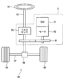
- FIG. 2 shows a configuration of a steering system 90 including the electric power steering device 8.
- the steering system 90 includes a steering wheel 91 that is a steering member, a steering shaft 92, a pinion gear 96, a rack shaft 97, wheels 98, an electric power steering device 8, and the like.
- the steering wheel 91 is connected to the steering shaft 92.
- the steering shaft 92 is provided with a torque sensor 85 that detects a steering torque Ts input by the driver operating the steering wheel 91.
- a pinion gear 96 is provided at the tip of the steering shaft 92.
- the pinion gear 96 is engaged with the rack shaft 97.
- a pair of wheels 98 are connected to both ends of the rack shaft 97 via tie rods or the like.
- the steering shaft 92 connected to the steering wheel 91 rotates.
- the rotational movement of the steering shaft 92 is converted into a linear movement of the rack shaft 97 by the pinion gear 96.
- the pair of wheels 98 are steered at an angle corresponding to the amount of displacement of the rack shaft 97.
- the electric power steering apparatus 8 includes a motor 80, a reduction gear 81 that reduces the rotation of the motor 80 and transmits the rotation to the steering shaft 92, a torque sensor 85, an ECU 10, and the like.
- the electric power steering apparatus 8 of the present embodiment is a so-called “column assist type”, but may be a so-called “rack assist type” that transmits the rotation of the motor 80 to the rack shaft 97.
- the motor 80 outputs an auxiliary torque for assisting the steering of the steering wheel 91 by the driver.
- the motor 80 is driven by power supplied from the battery 5 (see FIG. 1) as a power source. Rotate forward and reverse.
- the ECU 10 is provided with an IG terminal 11, a PIG terminal 12, and a ground terminal 13.
- the IG terminal 11 is connected to the battery 5 via a start switch 6 such as an ignition switch.
- the PIG terminal 12 is directly connected to the battery 5 without going through the start switch 6.
- the ground terminal 13 is connected to the ground.
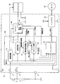
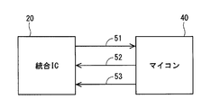
- the ECU 10 includes an integrated IC 20 as a monitoring unit, an inverter 30, and a microcomputer 40 as a control unit. As shown in FIG. 3, three communication lines 51, 52, 53 are provided between the integrated IC 20 and the microcomputer 40.
- the communication line 51 is used for information transmission from the integrated IC 20 to the microcomputer 40.
- the communication line 52 is used for information transmission from the microcomputer 40 to the integrated IC 20.
- the communication line 53 is used for outputting a clock signal for synchronizing the integrated IC 20 and the microcomputer 40.
- the clock signal is output from the microcomputer 40 to the integrated IC 20.
- Each process in the integrated IC 20 and the microcomputer 40 may be a software process by executing a program stored in advance in a substantial memory device such as a ROM by a CPU, or a hardware process by a dedicated electronic circuit. May be.
- the integrated IC 20 includes a power supply circuit 21, a communication circuit 22, an abnormality monitoring circuit 23, a reset circuit 24, a pre-driver 25 as a drive circuit, and the like.
- the power supply circuit 21 is, for example, a regulator, and adjusts the power supply voltage input via the IG terminal 11 to a predetermined voltage, and the adjusted voltage is transmitted to the communication circuit 22, the abnormality monitoring circuit 23, the reset circuit 24, This is supplied to the pre-driver 25, the microcomputer 40, the torque sensor 85, and the like.
- the communication circuit 22 communicates with the microcomputer 40 using the communication lines 51 to 53. Although the communication system of this embodiment is serial communication, parallel communication or the like may be used. When an abnormality occurs in communication with the microcomputer 40, the communication circuit 22 outputs communication abnormality information indicating that a communication abnormality has occurred to the abnormality monitoring circuit 23.
- the abnormality monitoring circuit 23 monitors the abnormality of the microcomputer 40.
- the abnormality monitoring circuit 23 determines that the microcomputer 40 is abnormal when the clock signal cannot be received based on the clock signal output from the microcomputer 40 at a predetermined interval if it is normal.
- the abnormality monitoring circuit 23 determines the abnormality of the microcomputer 40.
- the abnormality monitoring circuit 23 acquires communication abnormality information, internal abnormality information according to the result of internal monitoring executed based on the user program inside the microcomputer 40, separately from the BIST processing described later. .
- the abnormality monitoring circuit 23 outputs a reset command for resetting the microcomputer 40 to the reset circuit 24 when an abnormality of the microcomputer 40 or a communication abnormality occurs. Further, the abnormality monitoring circuit 23 outputs a stop command for stopping the motor 80 to the pre-driver 25 when an abnormality of the microcomputer 40 or a communication abnormality occurs.
- the reset circuit 24 outputs a reset signal based on the reset command to the microcomputer 40.
- the microcomputer 40 is reset when the reset signal is Lo, and the reset of the microcomputer 40 is canceled when the reset signal is Hi.
- the reset circuit 24 outputs a stop command for stopping the motor 80 to the pre-driver 25.
- the pre-driver 25 is supplied with the voltage input to the IG terminal 11 and the voltage regulated by the power supply circuit 21.
- the pre-driver 25 is a drive circuit that drives the inverter 30 based on a control signal from the microcomputer 40. Specifically, the pre-driver 25 generates a gate signal based on the control signal, and outputs the generated gate signal to the gate of each switching element of the inverter 30.
- the pre-driver 25 stops the output based on a signal from the abnormality monitoring circuit 23 or the reset circuit 24 when an abnormality of the microcomputer 40 or a communication abnormality occurs. Specifically, the output is stopped by turning off the gate signals of all the switching elements of the inverter 30. By stopping the output of the pre-driver 25 when an abnormality occurs, manual assist is provided, but self-steering due to driving of the motor 80 based on an abnormal command can be prevented.
- the inverter 30 has a switching element (not shown) that is bridge-connected. By switching on / off of the switching element, the voltage applied to the winding of the motor 80 is controlled. The inverter 30 is supplied with power from the PIG terminal 12.
- the microcomputer 40 controls driving of the motor 80 based on a signal from the torque sensor 85, a signal from a rotation angle sensor (not shown) that detects the rotation angle of the motor 80, and the like. Specifically, a control signal for controlling the on / off operation of the switching element of the inverter 30 is generated based on the steering torque, the electrical angle of the motor 80, and the like. The generated control signal is output to the pre-driver 25, and the operation of the switching element of the inverter 30 is controlled based on the control signal. The microcomputer 40 controls the driving of the motor 80 by controlling the switching element of the inverter 30.
- the microcomputer 40 has a BIST circuit 41 which is a self-diagnosis circuit and has a BIST function.
- BIST process the self-diagnosis process by the BIST circuit 41.
- user programs other than the BIST process are prohibited, and the user program does not operate. Therefore, no clock signal is output from the microcomputer 40 to the integrated IC 20 during the BIST process.
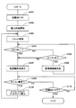
- the abnormality monitoring process of this embodiment will be described based on the flowchart shown in FIG.
- the process of FIG. 4 is mainly executed by the integrated IC 20.
- the start switch 6 is turned on.
- the power supply circuit 21 starts supplying power.
- the abnormality monitoring circuit 23 does not start the abnormality monitoring of the microcomputer 40 and disables the abnormality monitoring function.
- the reset circuit 24 sets the reset signal to Hi and releases the reset of the microcomputer 40. Also, the counting of the reset release time Xr, which is the elapsed time from the reset release, is started.
- the reset release time Xr can also be regarded as an elapsed time from the start of the BIST process.
- the BIST process is started. Further, in the microcomputer 40, when the BIST process is completed, a user program including an output of a clock signal is executed.
- the abnormality monitoring circuit 23 determines whether or not the BIST process of the microcomputer 40 has been completed. Details of the BIST processing end determination will be described later. When it is determined that the BIST process has been completed (S104: YES), the process proceeds to S107. When it is determined that the BIST process is being performed (S104: NO), the process proceeds to S105.
- the abnormality monitoring circuit 23 determines whether the reset release time Xr is less than the elapsed determination time Xr_th.
- the elapsed determination time Xr_th is set to a time longer than the time required when the BIST process is normally performed in the microcomputer 40.
- the process proceeds to S107.
- the process proceeds to S106.
- the abnormality monitoring circuit 23 continues the state where the abnormality monitoring function of the microcomputer 40 is invalidated, and returns to S104. That is, the abnormality monitoring circuit 23 does not monitor the microcomputer 40 when the microcomputer 40 is in the BIST process and the reset release time Xr is less than the elapsed determination time Xr_th.
- the abnormality monitoring circuit 23 receives the microcomputer.
- the abnormality monitoring function 40 is activated and abnormality monitoring of the microcomputer 40 is started.
- the abnormality monitoring circuit 23 determines whether or not the microcomputer 40 is abnormal. In the present embodiment, the abnormality monitoring circuit 23 determines that the microcomputer 40 is abnormal when the state in which the clock signal cannot be acquired continues for the abnormality confirmation time Xe. When it is determined that the microcomputer 40 is normal (S108: NO), the process proceeds to S110. When it is determined that the microcomputer 40 is abnormal (S108: YES), the process proceeds to S109.
- the abnormality monitoring circuit 23 outputs a reset command to the reset circuit 24.
- the reset circuit 24 switches the reset signal to Lo and resets the microcomputer 40.
- the abnormality monitoring circuit 23 and the reset circuit 24 output a stop command to the pre-driver 25. Receiving the stop command, the pre-driver 25 turns off the gate signals of all the switching elements.
- the process proceeds to S103. That is, when the reset time Xc has elapsed since the reset of the microcomputer 40, the reset signal is set to Hi and the reset of the microcomputer 40 is released. By shifting to S103 following S109, the microcomputer 40 is restarted. If the abnormality of the microcomputer 40 is not resolved even after restarting, the calculation by the microcomputer 40 may be stopped. The number of restarts until the microcomputer 40 is stopped may be set to any number.
- the abnormality monitoring circuit 23 determines whether or not the start switch 6 is turned off. When it is determined that the start switch 6 is not turned off (S110: NO), the process returns to S108. That is, the abnormality monitoring circuit 23 continues monitoring the abnormality of the microcomputer 40. When it is determined that the start switch 6 has been turned off (S110: YES), this process ends.
- the power supply circuit 21, the microcomputer 40, the abnormality monitoring circuit 23, the reset circuit 24, and the pre-driver 25 are turned off.
- the reset signal and clock signal of the reset circuit 24 are Lo.
- the power supply circuit 21 When the start switch 6 is turned on at time t10, the power supply circuit 21 is turned on at time t11. Further, when the power supply circuit 21 is turned on, the reset signal becomes Hi, thereby releasing the reset state of the microcomputer 40 and starting the BIST process. When the power supply circuit 21 is turned on, power supply to the abnormality monitoring circuit 23 is started. However, at the stage of time t11, the monitoring function of the microcomputer 40 in the abnormality monitoring circuit 23 is disabled.
- the microcomputer 40 starts the operation of the user program.
- the user program operates, output of a clock signal from the microcomputer 40 to the integrated IC 20 is started. Further, the operation of the pre-driver 25 is started based on a control signal from the microcomputer generated based on the user program.
- the abnormality monitoring of the microcomputer 40 by the abnormality monitoring circuit 23 is enabled.
- the number of times of determination is not limited to three, but may be any number, but is preferably a plurality of times.
- the clock signal may be recognized as Hi due to noise.
- the erroneous determination due to noise is prevented by clearing the count of the clock signal.
- FIG. 7B shows the count value of the clock signal.
- the abnormality monitoring circuit 23 enables the abnormality monitoring of the microcomputer 40 at time t13 when the determination number of clock signals are detected. Further, at time t14, an abnormality occurs in the microcomputer 40, and the clock signal is not output. When the period in which the clock signal is not detected continues for the abnormality confirmation time Xe, the abnormality monitoring circuit 23 determines the abnormality of the microcomputer 40 at time t15. When abnormality of the microcomputer 40 is determined by the abnormality monitoring circuit 23, the microcomputer 40 is reset and the operation of the pre-driver 25 is stopped by setting the reset signal to Lo.
- the reset signal is set to Hi at the time t16 when the reset time Xc has elapsed since the reset signal was set to Lo.
- the reset signal is set to Hi, the reset of the microcomputer 40 is released, and the BIST process is performed again. At this time, since the abnormality monitoring circuit 23 starts from the invalidation state, the reset does not occur repeatedly.
- FIG. 6 shows an example in which an abnormality occurs during the BIST process and the BIST process does not end normally.
- the operation up to time t21 is the same as the operation up to time t11 in FIG.
- the elapsed determination time Xr_th elapses after the reset of the microcomputer 40 is released, the BIST process is continued and the user program does not operate, so no clock signal is output. Therefore, at time t22 when the elapsed determination time Xr_th has elapsed from the reset cancellation, the monitoring function is disabled and the monitoring function in the abnormality monitoring circuit 23 is enabled. At this time, since the clock signal is not detected, the abnormality monitoring circuit 23 regards the microcomputer 40 as having an abnormality.
- the abnormality monitoring circuit 23 determines the abnormality of the microcomputer 40 at time t23 when the abnormality determination time Xe has elapsed from time t22, and sets the reset signal to Lo. Thereby, even when abnormality occurs in the microcomputer 40 before the end of the BIST process, the microcomputer 40 can be reset.
- the processing after the reset is the same as the example of FIG. 5, and at time t24 when the reset time Xc has elapsed, the reset signal is set to Hi, the reset of the microcomputer 40 is released, and the BIST processing is performed again. If the BIST process again ends normally, each process in the microcomputer 40 and abnormality monitoring in the abnormality monitoring circuit 23 are executed.
- FIG. 8 shows a comparative example in which the abnormality monitoring process in the abnormality monitoring circuit 23 is also performed during the BIST process.
- the processing up to time t81 in FIG. 8 is the same as the processing up to time t11 in FIG.
- the power supply circuit 21 when the power supply circuit 21 is turned on, the power supply to the abnormality monitoring circuit 23 is started, and at the same time, the abnormality monitoring process of the microcomputer 40 is started.
- the clock signal is not output from the microcomputer 40 to the integrated IC 20. Therefore, the abnormality monitoring circuit 23 considers that an abnormality has occurred in the microcomputer 40.
- the abnormality monitoring circuit 23 is the time before the BIST processing ends and at time t82 after the abnormality confirmation time Xe elapses. Confirm the abnormality.
- the microcomputer 40 is reset at time t82 and the reset of the microcomputer 40 is released at time t83, the BIST process is executed again from the beginning.
- the BIST process is repeatedly performed by confirming abnormality, resetting, and resetting of the microcomputer 40, so that the user program cannot be operated.
- the abnormality monitoring circuit 23 has a function of determining that the BIST process has ended (S104 in FIG. 4). Then, the abnormality monitoring function is invalidated during the BIST process of the microcomputer 40, and when the end of the BIST process is determined, the abnormality monitoring function is validated. Thereby, it is possible to prevent the BIST process in the microcomputer 40 from being erroneously determined as an abnormality of the microcomputer 40. For this reason, it is possible to avoid a reset caused by determining that the BIST process is abnormal in the microcomputer 40, and the user program can be appropriately started without repeating the BIST process and the reset. Further, the abnormality confirmation time Xe can be set regardless of the time required for the BIST process.
- the microcomputer 40 can be appropriately reset and restarted.
- the abnormality monitoring circuit 23 is invalidated again to prevent the user program from operating and preventing the microcomputer 40 from being reset and repeated BIST processing.
- the ECU 10 includes the microcomputer 40 and the integrated IC 20.
- the microcomputer 40 has a BIST circuit 41, and other processes such as a user program are prohibited during execution of the BIST process by the BIST circuit 41.
- the integrated IC 20 has an abnormality monitoring circuit 23 and a reset circuit 24.
- the abnormality monitoring circuit 23 monitors the abnormality of the microcomputer 40.
- the reset circuit 24 resets the microcomputer 40 when the abnormality monitoring circuit 23 determines the abnormality of the microcomputer 40.
- the abnormality monitoring circuit 23 can determine the end of the BIST process, invalidates the abnormality monitoring of the microcomputer 40 during execution of the BIST process, and starts the abnormality monitoring of the microcomputer 40 when it is determined that the BIST process has ended. To do.
- the microcomputer 40 since the microcomputer 40 is in the BIST process, it is possible to avoid erroneously determining that the other process is not executed as an abnormality of the microcomputer 40. Further, it is possible to prevent the reset of the microcomputer 40 and the BIST process from being repeated, and to appropriately start the user program.
- the abnormality monitoring circuit 23 starts monitoring the abnormality of the microcomputer 40 when an elapsed determination time Xr_th that is longer than the time required for the BIST processing has elapsed since the start of the self-diagnosis processing. Thereby, even if it is a case where abnormality arises in the microcomputer 40 during a BIST process, the microcomputer 40 can be reset appropriately.
- the microcomputer 40 outputs a clock signal to the integrated IC 20 at a predetermined interval after the BIST process is completed.
- the abnormality monitoring circuit 23 determines that the BIST process has been completed when a predetermined number of clock signals are detected within the determination time Xa.
- the abnormality monitoring circuit 23 determines the end of the BIST process based on the clock signal output by the user program. Thereby, it is possible to appropriately determine the end of the BIST process.
- the microcomputer 40 controls the driving of the motor 80.
- the abnormality monitoring circuit 23 stops the pre-driver 25 related to driving the motor 80 when the abnormality of the microcomputer 40 is confirmed. Thereby, malfunction of the motor 80 due to the abnormality of the microcomputer 40 can be prevented.
- the electric power steering device 8 includes an ECU 10 and a motor 80, and the motor 80 outputs an assist torque that assists the steering of the steering wheel 91 by the driver.
- the microcomputer 40 When the microcomputer 40 is abnormal, by stopping the pre-driver 25 and stopping the motor 80, manual steering can be performed, but self-steering in which the steering wheel 91 operates differently from the driver's intention can be prevented.
- the abnormality confirmation time Xe which is the time from the abnormality detection to the confirmation, as short as possible.
- the abnormality monitoring circuit 23 can avoid erroneously determining that the BIST process is abnormal in the microcomputer 40 by invalidating the abnormality monitoring during the BIST process of the microcomputer 40.
- the abnormality determination time Xe can be set without considering the time required. That is, by setting the abnormality confirmation time Xe short, when an abnormality occurs in the microcomputer 40, the driving of the motor 80 can be stopped quickly.
- the abnormality monitoring circuit determines whether or not the self-diagnosis process is completed based on the clock signal. In another embodiment, the abnormality monitoring circuit determines the end of the self-diagnosis process based on a signal other than the clock signal output from the control unit to the monitoring unit by a user program executed after the self-diagnosis process ends. May be. For example, the abnormality monitoring circuit is executed separately from the self-diagnosis process, and the completion of the self-diagnosis process may be determined based on the internal abnormality information according to the internal abnormality monitoring result based on the user program. Good. As a result, even when the communication between the control unit and the monitoring unit is asynchronous serial communication, the end determination of the self-diagnosis process can be appropriately performed even in an apparatus that does not use the clock signal.
- the integrated IC has a power supply circuit, a communication circuit, an abnormality monitoring circuit, a reset circuit, and a predriver.
- the power supply circuit, the communication circuit, the abnormality monitoring circuit, the reset circuit, and the predriver may be configured by a plurality of ICs.
- a self-diagnosis circuit is a BIST circuit.
- the self-diagnosis circuit is not limited to the BIST circuit, and may be any circuit that can self-monitor the control unit.
- control unit controls the driving of the motor.
- control unit may perform arithmetic processing other than motor control.
- the abnormality monitoring apparatus is applied to an electric power steering apparatus.
- the present invention may be applied to devices other than the electric power steering device.
Landscapes
- Engineering & Computer Science (AREA)
- Mechanical Engineering (AREA)
- Theoretical Computer Science (AREA)
- Transportation (AREA)
- Chemical & Material Sciences (AREA)
- Combustion & Propulsion (AREA)
- Physics & Mathematics (AREA)
- General Engineering & Computer Science (AREA)
- General Physics & Mathematics (AREA)
- Quality & Reliability (AREA)
- Automation & Control Theory (AREA)
- Steering Control In Accordance With Driving Conditions (AREA)
- Power Steering Mechanism (AREA)
- Debugging And Monitoring (AREA)
Abstract
The abnormality monitoring device is equipped with a control unit (40) and a monitoring unit (20). The control unit has a self-diagnosis circuit (41) for performing self-diagnosis processing, during which other processing is prohibited. The monitoring unit has an abnormality monitoring circuit (23) and a reset circuit (24). The abnormality monitoring circuit performs monitoring for an abnormality of the control unit. When an abnormality of the control unit is confirmed by the abnormality monitoring circuit, the reset circuit resets the control unit. The abnormality monitoring circuit determines whether or not the self-diagnosis processing has been completed, whereby the circuit disables the abnormality monitoring if the self-diagnosis processing is being executed, or starts the abnormality monitoring of the control unit if the self-diagnosis processing is determined as having been completed. Consequently, the control unit can be properly monitored for an abnormality.
Description
本出願は、2016年2月12日に出願された日本出願番号2016-24406号に基づくもので、ここにその記載内容を援用する。
This application is based on Japanese Patent Application No. 2016-24406 filed on February 12, 2016, the contents of which are incorporated herein by reference.
本開示は、異常監視装置、および、これを用いた電動パワーステアリング装置に関するものである。
The present disclosure relates to an abnormality monitoring device and an electric power steering device using the abnormality monitoring device.
従来、ウォッチドッグ信号を用いた異常監視が知られている。例えば特許文献1では、ウォッチドッグタイマ回路をウォッチドッグタイムアウト検出と、ウエイト時間測定の両方に用い、ウォッチドッグタイムアウト検出後、任意に設定されるウエイト時間が経過した場合、リセット、割り込み、制御信号等を発生させる。
Conventionally, abnormality monitoring using a watchdog signal is known. For example, in Patent Document 1, a watchdog timer circuit is used for both watchdog timeout detection and wait time measurement, and when an arbitrarily set wait time has elapsed after the watchdog timeout detection, a reset, an interrupt, a control signal, etc. Is generated.
ところで、昨今のマイコンには、BIST(Built In Self Test)機能を有しているものがある。BIST処理中にはユーザプログラムが動作しないため、例えばマイコンの外部からマイコンの異常を監視する場合、BIST処理中であることをマイコンの異常であると誤検出する虞がある。
By the way, some recent microcomputers have a BIST (Built In Self Test) function. Since the user program does not operate during the BIST process, for example, when monitoring an abnormality of the microcomputer from the outside of the microcomputer, there is a possibility that the BIST process is erroneously detected as an abnormality of the microcomputer.
本開示は、制御部の異常を適切に監視可能な異常監視装置、および、これを用いた電動パワーステアリング装置を提供することを目的とする。
This disclosure is intended to provide an abnormality monitoring apparatus capable of appropriately monitoring an abnormality of a control unit, and an electric power steering apparatus using the abnormality monitoring apparatus.
本開示の第1の態様によれば、異常監視装置は、制御部と、監視部と、を備える。制御部は、自己診断処理を実行する自己診断回路を有し、自己診断処理の実行中には他の処理が禁止される。監視部は、異常監視回路、および、リセット回路を有する。異常監視回路は、制御部の異常を監視する。リセット回路は、異常監視回路にて制御部の異常が確定された場合、制御部をリセットする。
According to the first aspect of the present disclosure, the abnormality monitoring device includes a control unit and a monitoring unit. The control unit has a self-diagnosis circuit that executes self-diagnosis processing, and other processing is prohibited during execution of the self-diagnosis processing. The monitoring unit has an abnormality monitoring circuit and a reset circuit. The abnormality monitoring circuit monitors the abnormality of the control unit. The reset circuit resets the control unit when the abnormality of the control unit is determined by the abnormality monitoring circuit.
異常監視回路は、自己診断処理の終了を判定可能であって、自己診断処理の実施中は制御部の異常監視を無効化し、自己診断処理が終了したと判定された場合、制御部の異常監視を開始する。
The abnormality monitoring circuit can determine the end of the self-diagnosis process, invalidates the abnormality monitoring of the control unit during the execution of the self-diagnosis process, and monitors the abnormality of the control unit when it is determined that the self-diagnosis process is completed. To start.
これにより、制御部が自己診断処理中であるために、他の処理が実行されていない状態を、制御部の異常であると誤判定するのを避けることができる。
This makes it possible to avoid erroneously determining that a state in which no other processing is being performed is an abnormality of the control unit because the control unit is performing self-diagnosis processing.
本開示の第2の態様によれば、電動パワーステアリング装置は、本開示の第1の態様による異常監視装置と、モータと、を備える。モータは、運転者による操舵部材の操舵を補助する補助トルクを出力する。
According to the second aspect of the present disclosure, the electric power steering apparatus includes the abnormality monitoring apparatus according to the first aspect of the present disclosure and a motor. The motor outputs an auxiliary torque that assists the driver in steering the steering member.
これにより、制御部が自己診断処理中であるために、他の処理が実行されていない状態を、制御部の異常であると誤判定するのを避けることができる。
This makes it possible to avoid erroneously determining that a state in which no other processing is being performed is an abnormality of the control unit because the control unit is performing self-diagnosis processing.
本開示についての上記目的およびその他の目的、特徴や利点は、添付の図面を参照しながら下記の詳細な記述により、より明確になる。図面において、
本開示の一実施形態による異常監視装置を示すブロック図であり、
本開示の一実施形態によるステアリングシステムを示す概略構成図であり、
本開示の一実施形態による統合ICとマイコンとの間の通信線を説明する図であり、
本開示の一実施形態による異常監視処理を説明するフローチャートであり、
本開示の一実施形態による異常監視処理を説明するタイムチャートであり、
本開示の一実施形態による異常監視処理を説明するタイムチャートであり、
本開示の一実施形態によるBIST処理の終了判定を説明するタイムチャートであり、
比較例による異常監視処理を説明するタイムチャートである。
The above and other objects, features and advantages of the present disclosure will become more apparent from the following detailed description with reference to the accompanying drawings. In the drawing
It is a block diagram showing an abnormality monitoring device according to an embodiment of the present disclosure, 1 is a schematic configuration diagram illustrating a steering system according to an embodiment of the present disclosure; It is a figure explaining the communication line between integrated IC and microcomputer by one embodiment of this indication, It is a flowchart illustrating an abnormality monitoring process according to an embodiment of the present disclosure, It is a time chart explaining the abnormality monitoring processing according to an embodiment of the present disclosure, It is a time chart explaining the abnormality monitoring processing according to an embodiment of the present disclosure, It is a time chart explaining the end judgment of BIST processing by one embodiment of this indication, It is a time chart explaining the abnormality monitoring process by a comparative example.
以下、本開示による異常監視装置、および、これを用いた電動パワーステアリング装置を図面に基づいて説明する。
Hereinafter, an abnormality monitoring apparatus according to the present disclosure and an electric power steering apparatus using the abnormality monitoring apparatus will be described with reference to the drawings.
(一実施形態)
本開示の一実施形態を図1~図7に示す。 (One embodiment)
One embodiment of the present disclosure is shown in FIGS.
本開示の一実施形態を図1~図7に示す。 (One embodiment)
One embodiment of the present disclosure is shown in FIGS.
図1および図2に示すように、異常監視装置としてのECU10は、モータ80とともに、運転者によるステアリング操作を補助する電動パワーステアリング装置8に適用される。
As shown in FIGS. 1 and 2, the ECU 10 as an abnormality monitoring device is applied to an electric power steering device 8 that assists a steering operation by a driver together with a motor 80.
図2は、電動パワーステアリング装置8を備えるステアリングシステム90の構成を示す。ステアリングシステム90は、操舵部材であるステアリングホイール91、ステアリングシャフト92、ピニオンギア96、ラック軸97、車輪98、および、電動パワーステアリング装置8等を有する。
FIG. 2 shows a configuration of a steering system 90 including the electric power steering device 8. The steering system 90 includes a steering wheel 91 that is a steering member, a steering shaft 92, a pinion gear 96, a rack shaft 97, wheels 98, an electric power steering device 8, and the like.
ステアリングホイール91は、ステアリングシャフト92と接続される。ステアリングシャフト92には、運転者がステアリングホイール91を操作することにより入力される操舵トルクTsを検出するトルクセンサ85が設けられる。ステアリングシャフト92の先端には、ピニオンギア96が設けられる。ピニオンギア96は、ラック軸97に噛み合っている。ラック軸97の両端には、タイロッド等を介して一対の車輪98が連結される。
The steering wheel 91 is connected to the steering shaft 92. The steering shaft 92 is provided with a torque sensor 85 that detects a steering torque Ts input by the driver operating the steering wheel 91. A pinion gear 96 is provided at the tip of the steering shaft 92. The pinion gear 96 is engaged with the rack shaft 97. A pair of wheels 98 are connected to both ends of the rack shaft 97 via tie rods or the like.
運転者がステアリングホイール91を回転させると、ステアリングホイール91に接続されたステアリングシャフト92が回転する。ステアリングシャフト92の回転運動は、ピニオンギア96によってラック軸97の直線運動に変換される。一対の車輪98は、ラック軸97の変位量に応じた角度に操舵される。
When the driver rotates the steering wheel 91, the steering shaft 92 connected to the steering wheel 91 rotates. The rotational movement of the steering shaft 92 is converted into a linear movement of the rack shaft 97 by the pinion gear 96. The pair of wheels 98 are steered at an angle corresponding to the amount of displacement of the rack shaft 97.
電動パワーステアリング装置8は、モータ80、モータ80の回転を減速してステアリングシャフト92に伝える減速ギア81、トルクセンサ85、および、ECU10等を備える。本実施形態の電動パワーステアリング装置8は、所謂「コラムアシストタイプ」であるが、モータ80の回転をラック軸97に伝える所謂「ラックアシストタイプ」としてもよい。
The electric power steering apparatus 8 includes a motor 80, a reduction gear 81 that reduces the rotation of the motor 80 and transmits the rotation to the steering shaft 92, a torque sensor 85, an ECU 10, and the like. The electric power steering apparatus 8 of the present embodiment is a so-called “column assist type”, but may be a so-called “rack assist type” that transmits the rotation of the motor 80 to the rack shaft 97.
モータ80は、運転者によるステアリングホイール91の操舵を補助する補助トルクを出力するものであって、電源としてのバッテリ5(図1参照)から電力が供給されることにより駆動され、減速ギア81を正逆回転させる。
The motor 80 outputs an auxiliary torque for assisting the steering of the steering wheel 91 by the driver. The motor 80 is driven by power supplied from the battery 5 (see FIG. 1) as a power source. Rotate forward and reverse.
図1に示すように、ECU10には、IG端子11、PIG端子12、および、グランド端子13が設けられる。IG端子11は、イグニッションスイッチ等である始動スイッチ6を経由して、バッテリ5と接続される。PIG端子12は、始動スイッチ6を経由せず、直接的にバッテリ5と接続される。グランド端子13は、グランドと接続される。
As shown in FIG. 1, the ECU 10 is provided with an IG terminal 11, a PIG terminal 12, and a ground terminal 13. The IG terminal 11 is connected to the battery 5 via a start switch 6 such as an ignition switch. The PIG terminal 12 is directly connected to the battery 5 without going through the start switch 6. The ground terminal 13 is connected to the ground.
ECU10は、監視部としての統合IC20、インバータ30、および、制御部としてのマイコン40等を備える。図3に示すように、統合IC20とマイコン40との間には、3本の通信線51、52、53が設けられる。通信線51は、統合IC20からマイコン40への情報伝達に用いられる。通信線52は、マイコン40から統合IC20への情報伝達に用いられる。通信線53は、統合IC20とマイコン40とを同期させるためのクロック信号の出力に用いられる。クロック信号は、マイコン40から統合IC20に出力される。
The ECU 10 includes an integrated IC 20 as a monitoring unit, an inverter 30, and a microcomputer 40 as a control unit. As shown in FIG. 3, three communication lines 51, 52, 53 are provided between the integrated IC 20 and the microcomputer 40. The communication line 51 is used for information transmission from the integrated IC 20 to the microcomputer 40. The communication line 52 is used for information transmission from the microcomputer 40 to the integrated IC 20. The communication line 53 is used for outputting a clock signal for synchronizing the integrated IC 20 and the microcomputer 40. The clock signal is output from the microcomputer 40 to the integrated IC 20.
統合IC20およびマイコン40における各処理は、ROM等の実体的なメモリ装置に予め記憶されたプログラムをCPUで実行することによるソフトウェア処理であってもよいし、専用の電子回路によるハードウェア処理であってもよい。
Each process in the integrated IC 20 and the microcomputer 40 may be a software process by executing a program stored in advance in a substantial memory device such as a ROM by a CPU, or a hardware process by a dedicated electronic circuit. May be.
図1に戻り、統合IC20は、電源回路21、通信回路22、異常監視回路23、リセット回路24、および、駆動回路としてのプリドライバ25等を有する。
1, the integrated IC 20 includes a power supply circuit 21, a communication circuit 22, an abnormality monitoring circuit 23, a reset circuit 24, a pre-driver 25 as a drive circuit, and the like.
電源回路21は、例えばレギュレータ等であって、IG端子11を経由して入力される電源電圧を所定の電圧に調圧し、調整された電圧を通信回路22、異常監視回路23、リセット回路24、プリドライバ25、マイコン40、および、トルクセンサ85等に供給する。
The power supply circuit 21 is, for example, a regulator, and adjusts the power supply voltage input via the IG terminal 11 to a predetermined voltage, and the adjusted voltage is transmitted to the communication circuit 22, the abnormality monitoring circuit 23, the reset circuit 24, This is supplied to the pre-driver 25, the microcomputer 40, the torque sensor 85, and the like.
通信回路22は、通信線51~53を用い、マイコン40と通信を行う。本実施形態の通信方式は、シリアル通信であるが、パラレル通信等であってもよい。通信回路22は、マイコン40との通信において異常が生じた場合、通信異常が生じたことを示す通信異常情報を異常監視回路23に出力する。
The communication circuit 22 communicates with the microcomputer 40 using the communication lines 51 to 53. Although the communication system of this embodiment is serial communication, parallel communication or the like may be used. When an abnormality occurs in communication with the microcomputer 40, the communication circuit 22 outputs communication abnormality information indicating that a communication abnormality has occurred to the abnormality monitoring circuit 23.
異常監視回路23は、マイコン40の異常を監視する。異常監視回路23は、正常であれば所定の間隔でマイコン40から出力されるクロック信号に基づき、クロック信号が受信できない場合、マイコン40の異常であると判定する。マイコン40が異常であると判定された状態、すなわちクロック信号が受信されない状態が異常確定時間Xeに亘って継続された場合、異常監視回路23は、マイコン40の異常を確定する。
The abnormality monitoring circuit 23 monitors the abnormality of the microcomputer 40. The abnormality monitoring circuit 23 determines that the microcomputer 40 is abnormal when the clock signal cannot be received based on the clock signal output from the microcomputer 40 at a predetermined interval if it is normal. When the state in which the microcomputer 40 is determined to be abnormal, that is, the state in which no clock signal is received continues for the abnormality determination time Xe, the abnormality monitoring circuit 23 determines the abnormality of the microcomputer 40.
また、異常監視回路23は、通信異常情報、および、後述するBIST処理とは別途にマイコン40の内部にてユーザプログラムに基づいて実行される内部監視の結果に応じた内部異常情報等を取得する。
Further, the abnormality monitoring circuit 23 acquires communication abnormality information, internal abnormality information according to the result of internal monitoring executed based on the user program inside the microcomputer 40, separately from the BIST processing described later. .
異常監視回路23は、マイコン40の異常や通信異常等が生じた場合、マイコン40をリセットするためのリセット指令をリセット回路24に出力する。また、異常監視回路23は、マイコン40の異常や通信異常等が生じた場合、モータ80を停止するための停止指令をプリドライバ25に出力する。
The abnormality monitoring circuit 23 outputs a reset command for resetting the microcomputer 40 to the reset circuit 24 when an abnormality of the microcomputer 40 or a communication abnormality occurs. Further, the abnormality monitoring circuit 23 outputs a stop command for stopping the motor 80 to the pre-driver 25 when an abnormality of the microcomputer 40 or a communication abnormality occurs.
リセット回路24は、リセット指令に基づくリセット信号を、マイコン40に出力する。本実施形態では、リセット信号がLoのとき、マイコン40をリセットし、リセット信号がHiのとき、マイコン40のリセットを解除するものとする。
The reset circuit 24 outputs a reset signal based on the reset command to the microcomputer 40. In the present embodiment, the microcomputer 40 is reset when the reset signal is Lo, and the reset of the microcomputer 40 is canceled when the reset signal is Hi.
また、リセット回路24は、モータ80を停止するための停止指令をプリドライバ25に出力する。
Also, the reset circuit 24 outputs a stop command for stopping the motor 80 to the pre-driver 25.
プリドライバ25には、IG端子11に入力された電圧、および、電源回路21にて調圧された電圧が供給される。プリドライバ25は、マイコン40からの制御信号に基づき、インバータ30を駆動させる駆動回路である。詳細には、プリドライバ25は、制御信号に基づいてゲート信号を生成し、生成されたゲート信号を、インバータ30の各スイッチング素子のゲートに出力する。
The pre-driver 25 is supplied with the voltage input to the IG terminal 11 and the voltage regulated by the power supply circuit 21. The pre-driver 25 is a drive circuit that drives the inverter 30 based on a control signal from the microcomputer 40. Specifically, the pre-driver 25 generates a gate signal based on the control signal, and outputs the generated gate signal to the gate of each switching element of the inverter 30.
プリドライバ25は、マイコン40の異常や通信異常等が生じた場合、異常監視回路23またはリセット回路24からの信号に基づき、出力を停止する。具体的には、インバータ30の全てのスイッチング素子のゲート信号を、オフ指令にすることで、出力を停止する。異常発生時にプリドライバ25の出力を停止することで、マニュアルアシストにはなるが、正常ではない指令に基づいてモータ80が駆動されることによるセルフステアリングを防ぐことができる。
The pre-driver 25 stops the output based on a signal from the abnormality monitoring circuit 23 or the reset circuit 24 when an abnormality of the microcomputer 40 or a communication abnormality occurs. Specifically, the output is stopped by turning off the gate signals of all the switching elements of the inverter 30. By stopping the output of the pre-driver 25 when an abnormality occurs, manual assist is provided, but self-steering due to driving of the motor 80 based on an abnormal command can be prevented.
インバータ30は、ブリッジ接続される図示しないスイッチング素子を有する。スイッチング素子のオンオフを切り替えることで、モータ80の巻線に印加される電圧が制御される。インバータ30には、PIG端子12からの電力が供給される。
The inverter 30 has a switching element (not shown) that is bridge-connected. By switching on / off of the switching element, the voltage applied to the winding of the motor 80 is controlled. The inverter 30 is supplied with power from the PIG terminal 12.
マイコン40は、トルクセンサ85からの信号、および、モータ80の回転角を検出する図示しない回転角センサからの信号等に基づき、モータ80の駆動を制御する。具体的には、操舵トルクおよびモータ80の電気角等に基づき、インバータ30のスイッチング素子のオンオフ作動を制御する制御信号を生成する。生成された制御信号は、プリドライバ25に出力され、制御信号に基づいてインバータ30のスイッチング素子の作動が制御される。マイコン40は、インバータ30のスイッチング素子を制御することで、モータ80の駆動を制御する。
The microcomputer 40 controls driving of the motor 80 based on a signal from the torque sensor 85, a signal from a rotation angle sensor (not shown) that detects the rotation angle of the motor 80, and the like. Specifically, a control signal for controlling the on / off operation of the switching element of the inverter 30 is generated based on the steering torque, the electrical angle of the motor 80, and the like. The generated control signal is output to the pre-driver 25, and the operation of the switching element of the inverter 30 is controlled based on the control signal. The microcomputer 40 controls the driving of the motor 80 by controlling the switching element of the inverter 30.
マイコン40は、自己診断回路であるBIST回路41を有し、BIST機能を有する。以下、BIST回路41による自己診断処理を、「BIST処理」という。マイコン40では、BIST処理中は、BIST処理以外のユーザプログラムが禁止され、ユーザプログラムが動作しない。そのため、BIST処理中には、マイコン40から統合IC20へのクロック信号の出力が行われない。
The microcomputer 40 has a BIST circuit 41 which is a self-diagnosis circuit and has a BIST function. Hereinafter, the self-diagnosis process by the BIST circuit 41 is referred to as “BIST process”. In the microcomputer 40, during the BIST process, user programs other than the BIST process are prohibited, and the user program does not operate. Therefore, no clock signal is output from the microcomputer 40 to the integrated IC 20 during the BIST process.
本実施形態の異常監視処理を図4に示すフローチャートに基づいて説明する。図4の処理は、主に統合IC20にて実行される。
The abnormality monitoring process of this embodiment will be described based on the flowchart shown in FIG. The process of FIG. 4 is mainly executed by the integrated IC 20.
S101にて、始動スイッチ6がオンされる。S102では、電源回路21は電力供給を開始する。ここで、異常監視回路23は、電源回路21からの電力供給が開始されたとしても、マイコン40の異常監視を開始せず、異常監視機能を無効化しておく。
In S101, the start switch 6 is turned on. In S102, the power supply circuit 21 starts supplying power. Here, even if the power supply from the power supply circuit 21 is started, the abnormality monitoring circuit 23 does not start the abnormality monitoring of the microcomputer 40 and disables the abnormality monitoring function.
本実施形態では、異常監視回路23に電力が供給されているが、マイコン40の異常監視を行っていないことを、「異常監視機能の無効化」とする。また、異常監視回路23にてマイコン40の異常監視を行っていることを、「異常監視機能の有効化」とする。
In the present embodiment, power is supplied to the abnormality monitoring circuit 23, but failure monitoring of the microcomputer 40 is referred to as "invalidation of abnormality monitoring function". Further, the fact that the abnormality monitoring circuit 23 monitors the abnormality of the microcomputer 40 is referred to as “validation of the abnormality monitoring function”.
S103では、リセット回路24は、リセット信号をHiとし、マイコン40のリセットを解除する。また、リセット解除からの経過時間であるリセット解除時間Xrの計時を開始する。リセット解除時間Xrは、BIST処理が開始してからの経過時間と捉えることもできる。
In S103, the reset circuit 24 sets the reset signal to Hi and releases the reset of the microcomputer 40. Also, the counting of the reset release time Xr, which is the elapsed time from the reset release, is started. The reset release time Xr can also be regarded as an elapsed time from the start of the BIST process.
マイコン40では、リセット信号がLoからHiに切り替わることでリセットが解除されると、BIST処理が開始される。また、マイコン40では、BIST処理が終了すると、クロック信号の出力を含むユーザプログラムが実行される。
In the microcomputer 40, when the reset is released by switching the reset signal from Lo to Hi, the BIST process is started. Further, in the microcomputer 40, when the BIST process is completed, a user program including an output of a clock signal is executed.
S104では、異常監視回路23は、マイコン40のBIST処理が終了したか否かを判断する。BIST処理の終了判定の詳細は、後述する。BIST処理が終了したと判断された場合(S104:YES)、S107へ移行する。BIST処理中であると判断された場合(S104:NO)、S105へ移行する。
In S104, the abnormality monitoring circuit 23 determines whether or not the BIST process of the microcomputer 40 has been completed. Details of the BIST processing end determination will be described later. When it is determined that the BIST process has been completed (S104: YES), the process proceeds to S107. When it is determined that the BIST process is being performed (S104: NO), the process proceeds to S105.
S105では、異常監視回路23は、リセット解除時間Xrが経過判定時間Xr_th未満か否かを判断する。経過判定時間Xr_thは、マイコン40での正常にBIST処理が行われる場合に要する時間よりも長い時間に設定される。リセット解除時間Xrが経過判定時間Xr_th以上であると判断された場合(S105:NO)、S107へ移行する。リセット解除時間Xrが経過判定時間Xr_th未満であると判断された場合(S105:YES)、S106へ移行する。
In S105, the abnormality monitoring circuit 23 determines whether the reset release time Xr is less than the elapsed determination time Xr_th. The elapsed determination time Xr_th is set to a time longer than the time required when the BIST process is normally performed in the microcomputer 40. When it is determined that the reset release time Xr is equal to or longer than the elapsed determination time Xr_th (S105: NO), the process proceeds to S107. When it is determined that the reset release time Xr is less than the elapsed determination time Xr_th (S105: YES), the process proceeds to S106.
S106では、異常監視回路23は、マイコン40の異常監視機能が無効化されている状態を継続し、S104に戻る。すなわち、異常監視回路23は、マイコン40がBIST処理中であって、リセット解除時間Xrが経過判定時間Xr_th未満の場合、マイコン40の異常監視を行わない。
In S106, the abnormality monitoring circuit 23 continues the state where the abnormality monitoring function of the microcomputer 40 is invalidated, and returns to S104. That is, the abnormality monitoring circuit 23 does not monitor the microcomputer 40 when the microcomputer 40 is in the BIST process and the reset release time Xr is less than the elapsed determination time Xr_th.
BIST処理が終了したと判断された場合(S104:YES)、または、リセット解除時間Xrが経過判定時間Xr_th以上の場合(S105:NO)に続いて移行するS107では、異常監視回路23は、マイコン40の異常監視機能を有効化し、マイコン40の異常監視を開始する。
When it is determined that the BIST process has been completed (S104: YES), or when the reset release time Xr is equal to or greater than the elapsed determination time Xr_th (S105: NO), the abnormality monitoring circuit 23 receives the microcomputer. The abnormality monitoring function 40 is activated and abnormality monitoring of the microcomputer 40 is started.
S108では、異常監視回路23は、マイコン40が異常か否かを判断する。本実施形態では、異常監視回路23は、クロック信号が取得できない状態が異常確定時間Xeに亘って継続された場合、マイコン40の異常と判定する。マイコン40が正常であると判断された場合(S108:NO)、S110へ移行する。マイコン40が異常であると判断された場合(S108:YES)、S109へ移行する。
In S108, the abnormality monitoring circuit 23 determines whether or not the microcomputer 40 is abnormal. In the present embodiment, the abnormality monitoring circuit 23 determines that the microcomputer 40 is abnormal when the state in which the clock signal cannot be acquired continues for the abnormality confirmation time Xe. When it is determined that the microcomputer 40 is normal (S108: NO), the process proceeds to S110. When it is determined that the microcomputer 40 is abnormal (S108: YES), the process proceeds to S109.
S109では、異常監視回路23は、リセット指令をリセット回路24に出力する。リセット回路24は、リセット信号をLoに切り替え、マイコン40をリセットする。また、異常監視回路23およびリセット回路24は、停止指令をプリドライバ25に出力する。停止指令を受けたプリドライバ25は、全てのスイッチング素子のゲート信号を、オフ指令にする。
In S109, the abnormality monitoring circuit 23 outputs a reset command to the reset circuit 24. The reset circuit 24 switches the reset signal to Lo and resets the microcomputer 40. In addition, the abnormality monitoring circuit 23 and the reset circuit 24 output a stop command to the pre-driver 25. Receiving the stop command, the pre-driver 25 turns off the gate signals of all the switching elements.
マイコン40のリセットからリセット時間Xcが経過した後、S103に移行する。すなわち、マイコン40のリセットからリセット時間Xcが経過した場合、リセット信号をHiとし、マイコン40のリセットを解除する。S109に続いてS103に移行することで、マイコン40が再起動される。再起動してもマイコン40の異常が解消されない場合、マイコン40による演算を停止するようにしてもよい。マイコン40を停止するまでの再起動回数は、何回に設定してもよい。
After the reset time Xc has elapsed since the reset of the microcomputer 40, the process proceeds to S103. That is, when the reset time Xc has elapsed since the reset of the microcomputer 40, the reset signal is set to Hi and the reset of the microcomputer 40 is released. By shifting to S103 following S109, the microcomputer 40 is restarted. If the abnormality of the microcomputer 40 is not resolved even after restarting, the calculation by the microcomputer 40 may be stopped. The number of restarts until the microcomputer 40 is stopped may be set to any number.
マイコン40が正常であると判断された場合(S108:NO)に移行するS110では、異常監視回路23は、始動スイッチ6がオフされたか否かを判断する。始動スイッチ6がオフされていないと判断された場合(S110:NO)、S108に戻る。すなわち、異常監視回路23は、マイコン40の異常監視を継続する。始動スイッチ6がオフされたと判断された場合(S110:YES)、本処理を終了する。
When it is determined that the microcomputer 40 is normal (S108: NO), the abnormality monitoring circuit 23 determines whether or not the start switch 6 is turned off. When it is determined that the start switch 6 is not turned off (S110: NO), the process returns to S108. That is, the abnormality monitoring circuit 23 continues monitoring the abnormality of the microcomputer 40. When it is determined that the start switch 6 has been turned off (S110: YES), this process ends.
本実施形態の異常監視処理を図5~図7のタイムチャートに基づいて説明する。
The abnormality monitoring process of the present embodiment will be described based on the time charts of FIGS.
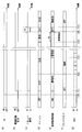
図5では、(a)が始動スイッチ6のオンオフ状態、(b)が電源回路21の出力状態、(c)がリセット信号、(d)がマイコン40の状態、(e)が異常監視回路23の状態、(f)がプリドライバの状態、(g)がマイコン40からのクロック信号を示す。図6および図8も同様である。また、図5~図8では、始動スイッチ6を「IG」、クロック信号を「CLK」と記載する。なお、説明のため、タイムスケールを適宜変更しているため、図におけるタイムスケールは、必ずしも実際のタイムスケールとは一致しない。
5, (a) is an on / off state of the start switch 6, (b) is an output state of the power supply circuit 21, (c) is a reset signal, (d) is a state of the microcomputer 40, and (e) is an abnormality monitoring circuit 23. (F) shows the state of the pre-driver, and (g) shows the clock signal from the microcomputer 40. The same applies to FIGS. 6 and 8. In FIGS. 5 to 8, the start switch 6 is described as “IG”, and the clock signal is described as “CLK”. For the sake of explanation, the time scale is changed as appropriate, so the time scale in the figure does not necessarily match the actual time scale.
図5に示すように、始動スイッチ6がオンされる時刻t10以前は、電源回路21、マイコン40、異常監視回路23、リセット回路24、および、プリドライバ25はオフされている。また、リセット回路24のリセット信号およびクロック信号はLoである。
As shown in FIG. 5, before the time t10 when the start switch 6 is turned on, the power supply circuit 21, the microcomputer 40, the abnormality monitoring circuit 23, the reset circuit 24, and the pre-driver 25 are turned off. The reset signal and clock signal of the reset circuit 24 are Lo.
時刻t10にて、始動スイッチ6がオンされると、時刻t11にて、電源回路21がオンされる。また、電源回路21がオンされると、リセット信号がHiとなることでマイコン40のリセット状態が解除され、BIST処理が開始される。また、電源回路21がオンされると、異常監視回路23への電力供給が開始されるが、時刻t11の段階では、異常監視回路23におけるマイコン40の監視機能は無効化されている。
When the start switch 6 is turned on at time t10, the power supply circuit 21 is turned on at time t11. Further, when the power supply circuit 21 is turned on, the reset signal becomes Hi, thereby releasing the reset state of the microcomputer 40 and starting the BIST process. When the power supply circuit 21 is turned on, power supply to the abnormality monitoring circuit 23 is started. However, at the stage of time t11, the monitoring function of the microcomputer 40 in the abnormality monitoring circuit 23 is disabled.
時刻t12にて、正常にBIST処理が終了すると、マイコン40では、ユーザプログラムの動作が開始される。ユーザプログラムが動作すると、マイコン40から統合IC20へのクロック信号の出力が開始される。また、ユーザプログラムに基づいて生成されるマイコンからの制御信号に基づき、プリドライバ25の動作を開始する。
When the BIST process ends normally at time t12, the microcomputer 40 starts the operation of the user program. When the user program operates, output of a clock signal from the microcomputer 40 to the integrated IC 20 is started. Further, the operation of the pre-driver 25 is started based on a control signal from the microcomputer generated based on the user program.
本実施形態では、BIST処理中は、ユーザプログラムが実行されないという性質を利用し、クロック信号を判定時間Xa内に判定回数(例えば3回)受信すると、ユーザプログラムの動作が開始されたと判断し、異常監視回路23でのマイコン40の異常監視を有効にする。
In the present embodiment, using the property that the user program is not executed during the BIST process, it is determined that the operation of the user program is started when the clock signal is received the determination times (for example, 3 times) within the determination time Xa, The abnormality monitoring of the microcomputer 40 by the abnormality monitoring circuit 23 is enabled.
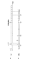
判定回数は、3回に限らず何回でもよいが、複数回であることが望ましい。例えば図7(a)に示すように、ノイズにより、クロック信号がHiと認識される虞がある。判定時間Xa内に判定回数のクロック信号が受信されなかった場合、クロック信号のカウントをクリアすることで、ノイズによる誤判定を防いでいる。なお、図7(b)は、クロック信号のカウント値を示している。
* The number of times of determination is not limited to three, but may be any number, but is preferably a plurality of times. For example, as shown in FIG. 7A, the clock signal may be recognized as Hi due to noise. When the number of determinations of the clock signal is not received within the determination time Xa, the erroneous determination due to noise is prevented by clearing the count of the clock signal. FIG. 7B shows the count value of the clock signal.
具体的には、図7に示すように、時刻t31にてクロック信号が検出されてから、判定時間Xaが経過するまでに、判定回数のクロック信号が検出されなかった場合、時刻t31のクロック信号をノイズとみなし、判定時間Xaが経過した時刻t33にてクロック信号のカウントをクリアする。
Specifically, as shown in FIG. 7, when the determination number of clock signals is not detected before the determination time Xa elapses after the clock signal is detected at time t31, the clock signal at time t31 is detected. Is counted as noise, and the clock signal count is cleared at time t33 when the determination time Xa has elapsed.
また、時刻t35にて、マイコン40にてBIST処理が終了し、ユーザプログラムが正常に動き出すと、所定の間隔でクロック信号が送信されるので、異常監視回路23は、判定回数のクロック信号を受信した時刻t37にて、マイコン40のBIST処理が終了したと判定し、監視機能を有効化し、マイコン40の異常監視を開始する。
At time t35, when the BIST process is completed in the microcomputer 40 and the user program starts operating normally, a clock signal is transmitted at a predetermined interval, so that the abnormality monitoring circuit 23 receives the clock signal of the number of determinations. At the time t37, it is determined that the BIST process of the microcomputer 40 has been completed, the monitoring function is validated, and abnormality monitoring of the microcomputer 40 is started.
図5に戻り、異常監視回路23は、判定回数のクロック信号が検出された時刻t13にて、マイコン40の異常監視を有効にする。また、時刻t14にて、マイコン40に異常が発生し、クロック信号が出力されなくなるものとする。異常監視回路23は、クロック信号が検出されない期間が異常確定時間Xeに亘って継続されると、時刻t15にて、マイコン40の異常を確定する。異常監視回路23にてマイコン40の異常が確定されると、リセット信号をLoにすることで、マイコン40をリセットするとともに、プリドライバ25の動作を停止する。
Referring back to FIG. 5, the abnormality monitoring circuit 23 enables the abnormality monitoring of the microcomputer 40 at time t13 when the determination number of clock signals are detected. Further, at time t14, an abnormality occurs in the microcomputer 40, and the clock signal is not output. When the period in which the clock signal is not detected continues for the abnormality confirmation time Xe, the abnormality monitoring circuit 23 determines the abnormality of the microcomputer 40 at time t15. When abnormality of the microcomputer 40 is determined by the abnormality monitoring circuit 23, the microcomputer 40 is reset and the operation of the pre-driver 25 is stopped by setting the reset signal to Lo.
また、リセット信号をLoにしてから、リセット時間Xcが経過した時刻t16にて、リセット信号をHiにする。リセット信号をHiにすると、マイコン40のリセットが解除され、再度、BIST処理が行われる。このとき、異常監視回路23は、無効化状態から始まるので、リセットが繰り返し起こることはない。
Also, the reset signal is set to Hi at the time t16 when the reset time Xc has elapsed since the reset signal was set to Lo. When the reset signal is set to Hi, the reset of the microcomputer 40 is released, and the BIST process is performed again. At this time, since the abnormality monitoring circuit 23 starts from the invalidation state, the reset does not occur repeatedly.
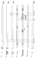
図6は、BIST処理中に異常が生じ、BIST処理が正常に終了しない場合の例である。
FIG. 6 shows an example in which an abnormality occurs during the BIST process and the BIST process does not end normally.
時刻t21までの動作は、図5の時刻t11までの動作と同様である。図6の例では、マイコン40のリセットが解除されてから経過判定時間Xr_thが経過しても、BIST処理が継続されており、ユーザプログラムが動作しないので、クロック信号が出力されない。そのため、リセット解除から経過判定時間Xr_thが経過した時刻t22にて、監視機能の無効化を解除し、異常監視回路23における監視機能を有効化する。このとき、クロック信号が検出されないので、異常監視回路23は、マイコン40に異常が生じているとみなす。
The operation up to time t21 is the same as the operation up to time t11 in FIG. In the example of FIG. 6, even if the elapsed determination time Xr_th elapses after the reset of the microcomputer 40 is released, the BIST process is continued and the user program does not operate, so no clock signal is output. Therefore, at time t22 when the elapsed determination time Xr_th has elapsed from the reset cancellation, the monitoring function is disabled and the monitoring function in the abnormality monitoring circuit 23 is enabled. At this time, since the clock signal is not detected, the abnormality monitoring circuit 23 regards the microcomputer 40 as having an abnormality.
また、異常監視回路23は、時刻t22から異常確定時間Xeが経過した時刻t23にて、マイコン40の異常を確定し、リセット信号をLoにする。これにより、BIST処理の終了前にマイコン40に異常が生じた場合においても、マイコン40をリセットすることができる。
Further, the abnormality monitoring circuit 23 determines the abnormality of the microcomputer 40 at time t23 when the abnormality determination time Xe has elapsed from time t22, and sets the reset signal to Lo. Thereby, even when abnormality occurs in the microcomputer 40 before the end of the BIST process, the microcomputer 40 can be reset.
リセット後の処理は、図5の例と同様であり、リセット時間Xcが経過した時刻t24にて、リセット信号をHiとし、マイコン40のリセットを解除し、再度、BIST処理を行う。再度のBIST処理が正常に終了すれば、マイコン40における各処理、異常監視回路23における異常監視が実行される。
The processing after the reset is the same as the example of FIG. 5, and at time t24 when the reset time Xc has elapsed, the reset signal is set to Hi, the reset of the microcomputer 40 is released, and the BIST processing is performed again. If the BIST process again ends normally, each process in the microcomputer 40 and abnormality monitoring in the abnormality monitoring circuit 23 are executed.
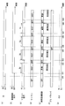
図8は、異常監視回路23における異常監視処理が、BIST処理中にも行われる場合の比較例である。
FIG. 8 shows a comparative example in which the abnormality monitoring process in the abnormality monitoring circuit 23 is also performed during the BIST process.
図8の時刻t81までの処理は、図5の時刻t11までの処理と同様である。比較例では、電源回路21のオンに伴って異常監視回路23への電力供給が開始されると同時に、マイコン40の異常監視処理が開始される。このとき、マイコン40はBIST処理中であり、ユーザプログラムが動作していないので、マイコン40から統合IC20へのクロック信号の出力が行われない。そのため、異常監視回路23は、マイコン40に異常が生じているとみなす。
The processing up to time t81 in FIG. 8 is the same as the processing up to time t11 in FIG. In the comparative example, when the power supply circuit 21 is turned on, the power supply to the abnormality monitoring circuit 23 is started, and at the same time, the abnormality monitoring process of the microcomputer 40 is started. At this time, since the microcomputer 40 is in the BIST process and the user program is not operating, the clock signal is not output from the microcomputer 40 to the integrated IC 20. Therefore, the abnormality monitoring circuit 23 considers that an abnormality has occurred in the microcomputer 40.
ここで、異常確定時間Xeが、マイコン40におけるBIST処理に要する時間より短いと、異常監視回路23は、BIST処理終了前であって、異常確定時間Xe経過後の時刻t82にて、マイコン40の異常を確定する。また、マイコン40の異常確定に伴い、時刻t82にてマイコン40をリセットし、時刻t83にてマイコン40のリセットを解除すると、再度、BIST処理が最初から実行される。
Here, if the abnormality confirmation time Xe is shorter than the time required for the BIST processing in the microcomputer 40, the abnormality monitoring circuit 23 is the time before the BIST processing ends and at time t82 after the abnormality confirmation time Xe elapses. Confirm the abnormality. When the microcomputer 40 is reset at time t82 and the reset of the microcomputer 40 is released at time t83, the BIST process is executed again from the beginning.
時刻t84~時刻t85、時刻t86~時刻t87、時刻t88~時刻t89においても、同様に、マイコン40の異常確定、リセット、リセット解除によるBIST処理が繰り返されるので、ユーザプログラムを動作させることができない。
Similarly, from time t84 to time t85, from time t86 to time t87, and from time t88 to time t89, the BIST process is repeatedly performed by confirming abnormality, resetting, and resetting of the microcomputer 40, so that the user program cannot be operated.
これに対し、本実施形態では、異常監視回路23は、BIST処理が終了したことを判定する機能(図4中のS104)を有している。そして、マイコン40のBIST処理中は異常監視機能を無効化し、BIST処理の終了が判定された場合、異常監視機能を有効にしている。これにより、マイコン40におけるBIST処理を、マイコン40の異常と誤判定するのを防ぐことができる。そのため、BIST処理をマイコン40の異常と判定することで生じるリセットを回避することができ、BIST処理およびリセットが繰り返されることがなく、適切にユーザプログラムを開始することができる。また、BIST処理に要する時間によらず、異常確定時間Xeを設定することができる。
On the other hand, in the present embodiment, the abnormality monitoring circuit 23 has a function of determining that the BIST process has ended (S104 in FIG. 4). Then, the abnormality monitoring function is invalidated during the BIST process of the microcomputer 40, and when the end of the BIST process is determined, the abnormality monitoring function is validated. Thereby, it is possible to prevent the BIST process in the microcomputer 40 from being erroneously determined as an abnormality of the microcomputer 40. For this reason, it is possible to avoid a reset caused by determining that the BIST process is abnormal in the microcomputer 40, and the user program can be appropriately started without repeating the BIST process and the reset. Further, the abnormality confirmation time Xe can be set regardless of the time required for the BIST process.
また、マイコン40のリセットが解除され、BIST処理が開始されてから、経過判定時間Xr_thが経過した場合、異常監視回路23の監視機能を有効化するので、BIST処理中にマイコン40に異常が生じた場合においても、マイコン40のリセットおよび再起動を適切に行うことができる。
Further, when the elapsed determination time Xr_th has elapsed since the reset of the microcomputer 40 was released and the BIST process was started, the monitoring function of the abnormality monitoring circuit 23 is validated, so that an abnormality occurs in the microcomputer 40 during the BIST process. Even in this case, the microcomputer 40 can be appropriately reset and restarted.
マイコン40のリセット後は、異常監視回路23を再度無効化することで、ユーザプログラムが動作せず、マイコン40のリセット、BIST処理が繰り返されるのを防ぐことができる。
After resetting the microcomputer 40, the abnormality monitoring circuit 23 is invalidated again to prevent the user program from operating and preventing the microcomputer 40 from being reset and repeated BIST processing.
以上説明したように、ECU10は、マイコン40と、統合IC20と、を備える。
As described above, the ECU 10 includes the microcomputer 40 and the integrated IC 20.
マイコン40は、BIST回路41を有し、BIST回路41によるBIST処理の実行中には、ユーザプログラム等の他の処理が禁止される。
The microcomputer 40 has a BIST circuit 41, and other processes such as a user program are prohibited during execution of the BIST process by the BIST circuit 41.
統合IC20は、異常監視回路23、および、リセット回路24を有する。異常監視回路23は、マイコン40の異常を監視する。リセット回路24は、異常監視回路23にてマイコン40の異常が確定された場合、マイコン40をリセットする。
The integrated IC 20 has an abnormality monitoring circuit 23 and a reset circuit 24. The abnormality monitoring circuit 23 monitors the abnormality of the microcomputer 40. The reset circuit 24 resets the microcomputer 40 when the abnormality monitoring circuit 23 determines the abnormality of the microcomputer 40.
異常監視回路23は、BIST処理の終了を判定可能であって、BIST処理の実行中はマイコン40の異常監視を無効化し、BIST処理が終了したと判定された場合、マイコン40の異常監視を開始する。
The abnormality monitoring circuit 23 can determine the end of the BIST process, invalidates the abnormality monitoring of the microcomputer 40 during execution of the BIST process, and starts the abnormality monitoring of the microcomputer 40 when it is determined that the BIST process has ended. To do.
これにより、マイコン40がBIST処理中であるために、他の処理が実行されていない状態を、マイコン40の異常であると誤判定するのを避けることができる。また、マイコン40のリセットとBIST処理とが繰り返されるのを防ぎ、ユーザプログラムを適切に開始させることができる。
Thereby, since the microcomputer 40 is in the BIST process, it is possible to avoid erroneously determining that the other process is not executed as an abnormality of the microcomputer 40. Further, it is possible to prevent the reset of the microcomputer 40 and the BIST process from being repeated, and to appropriately start the user program.
異常監視回路23は、自己診断処理の開始から、BIST処理に要する時間より長い経過判定時間Xr_thが経過した場合、マイコン40の異常監視を開始する。これにより、BIST処理中にマイコン40に異常が生じた場合であっても、適切にマイコン40をリセットすることができる。
The abnormality monitoring circuit 23 starts monitoring the abnormality of the microcomputer 40 when an elapsed determination time Xr_th that is longer than the time required for the BIST processing has elapsed since the start of the self-diagnosis processing. Thereby, even if it is a case where abnormality arises in the microcomputer 40 during a BIST process, the microcomputer 40 can be reset appropriately.
マイコン40は、BIST処理が終了した後、クロック信号を所定の間隔で統合IC20に出力する。
The microcomputer 40 outputs a clock signal to the integrated IC 20 at a predetermined interval after the BIST process is completed.
異常監視回路23は、判定時間Xa内に所定回数のクロック信号を検出した場合、BIST処理が終了したと判定する。
The abnormality monitoring circuit 23 determines that the BIST process has been completed when a predetermined number of clock signals are detected within the determination time Xa.
BIST処理中はユーザプログラムが動作しない性質を利用し、異常監視回路23は、ユーザプログラムにて出力されるクロック信号に基づいて、BIST処理の終了判定を行う。これにより、BIST処理の終了を適切に判定することができる。
Using the property that the user program does not operate during the BIST process, the abnormality monitoring circuit 23 determines the end of the BIST process based on the clock signal output by the user program. Thereby, it is possible to appropriately determine the end of the BIST process.
マイコン40は、モータ80の駆動を制御するものである。異常監視回路23は、マイコン40の異常が確定された場合、モータ80の駆動に係るプリドライバ25を停止する。これにより、マイコン40の異常によるモータ80の誤作動を防ぐことができる。
The microcomputer 40 controls the driving of the motor 80. The abnormality monitoring circuit 23 stops the pre-driver 25 related to driving the motor 80 when the abnormality of the microcomputer 40 is confirmed. Thereby, malfunction of the motor 80 due to the abnormality of the microcomputer 40 can be prevented.
電動パワーステアリング装置8は、ECU10と、モータ80と、を備え、モータ80は、運転者によるステアリングホイール91の操舵を補助する補助トルクを出力する。マイコン40の異常時に、プリドライバ25を停止してモータ80を停止することで、マニュアルアシストにはなるが、ステアリングホイール91が運転者の意図と異なる動作となるセルフステアリングを防ぐことができる。
The electric power steering device 8 includes an ECU 10 and a motor 80, and the motor 80 outputs an assist torque that assists the steering of the steering wheel 91 by the driver. When the microcomputer 40 is abnormal, by stopping the pre-driver 25 and stopping the motor 80, manual steering can be performed, but self-steering in which the steering wheel 91 operates differently from the driver's intention can be prevented.
電動パワーステアリング装置8では、セルフステアリング等の誤動作を防ぐべく、マイコン40に異常が生じた場合、異常検出から確定までの時間である異常確定時間Xeを可及的短く設定することが望ましい。本実施形態では、異常監視回路23は、マイコン40のBIST処理中には異常監視を無効化することで、BIST処理をマイコン40の異常と誤判定するのを避けることができるので、BIST処理に要する時間を考慮せず、異常確定時間Xeを設定可能である。すなわち、異常確定時間Xeを短く設定することで、マイコン40に異常が生じた場合、モータ80の駆動を速やかに停止させることができる。
In the electric power steering device 8, in order to prevent malfunction such as self-steering, when an abnormality occurs in the microcomputer 40, it is desirable to set the abnormality confirmation time Xe, which is the time from the abnormality detection to the confirmation, as short as possible. In the present embodiment, the abnormality monitoring circuit 23 can avoid erroneously determining that the BIST process is abnormal in the microcomputer 40 by invalidating the abnormality monitoring during the BIST process of the microcomputer 40. The abnormality determination time Xe can be set without considering the time required. That is, by setting the abnormality confirmation time Xe short, when an abnormality occurs in the microcomputer 40, the driving of the motor 80 can be stopped quickly.
(他の実施形態)
(ア)異常監視回路
上記実施形態では、異常監視回路は、クロック信号に基づき、自己診断処理の終了判定を行っている。他の実施形態では、異常監視回路は、自己診断処理終了後に実行されるユーザプログラムにより制御部から監視部に出力されるクロック信号以外の他の信号に基づいて、自己診断処理の終了判定を行ってもよい。例えば、異常監視回路は、自己診断処理とは別途に実行されるものであって、ユーザプログラムに基づく内部異常監視結果に応じた内部異常情報に基づいて、自己診断処理の終了判定を行ってもよい。これにより、制御部と監視部との通信が非同期のシリアル通信である場合等、クロック信号を用いない装置においても、自己診断処理の終了判定を適切に行うことができる。 (Other embodiments)
(A) Abnormality monitoring circuit In the above-described embodiment, the abnormality monitoring circuit determines whether or not the self-diagnosis process is completed based on the clock signal. In another embodiment, the abnormality monitoring circuit determines the end of the self-diagnosis process based on a signal other than the clock signal output from the control unit to the monitoring unit by a user program executed after the self-diagnosis process ends. May be. For example, the abnormality monitoring circuit is executed separately from the self-diagnosis process, and the completion of the self-diagnosis process may be determined based on the internal abnormality information according to the internal abnormality monitoring result based on the user program. Good. As a result, even when the communication between the control unit and the monitoring unit is asynchronous serial communication, the end determination of the self-diagnosis process can be appropriately performed even in an apparatus that does not use the clock signal.
(イ)統合IC
上記実施形態では、統合ICが、電源回路、通信回路、異常監視回路、リセット回路、および、プリドライバを有する。他の実施形態では、電源回路、通信回路、異常監視回路、リセット回路、および、プリドライバが、複数のICにより構成されていてもよい。 (A) Integrated IC
In the above embodiment, the integrated IC has a power supply circuit, a communication circuit, an abnormality monitoring circuit, a reset circuit, and a predriver. In another embodiment, the power supply circuit, the communication circuit, the abnormality monitoring circuit, the reset circuit, and the predriver may be configured by a plurality of ICs.
(ウ)制御部
上記実施形態では、自己診断回路は、BIST回路である。他の実施形態では、自己診断回路は、BIST回路に限らず、制御部を自己監視できるどのような回路であってもよい。 (C) Control part In the said embodiment, a self-diagnosis circuit is a BIST circuit. In another embodiment, the self-diagnosis circuit is not limited to the BIST circuit, and may be any circuit that can self-monitor the control unit.
上記実施形態では、自己診断回路は、BIST回路である。他の実施形態では、自己診断回路は、BIST回路に限らず、制御部を自己監視できるどのような回路であってもよい。 (C) Control part In the said embodiment, a self-diagnosis circuit is a BIST circuit. In another embodiment, the self-diagnosis circuit is not limited to the BIST circuit, and may be any circuit that can self-monitor the control unit.
上記実施形態では、制御部は、モータの駆動を制御するものである。他の実施形態では、制御部は、モータ制御以外の演算処理を行うものであってもよい。
In the above embodiment, the control unit controls the driving of the motor. In other embodiments, the control unit may perform arithmetic processing other than motor control.
(エ)異常監視装置
上記実施形態では、異常監視装置は、電動パワーステアリング装置に適用される。他の実施形態では、電動パワーステアリング装置以外の装置に適用してもよい。 (D) Abnormality monitoring apparatus In the above embodiment, the abnormality monitoring apparatus is applied to an electric power steering apparatus. In other embodiments, the present invention may be applied to devices other than the electric power steering device.
上記実施形態では、異常監視装置は、電動パワーステアリング装置に適用される。他の実施形態では、電動パワーステアリング装置以外の装置に適用してもよい。 (D) Abnormality monitoring apparatus In the above embodiment, the abnormality monitoring apparatus is applied to an electric power steering apparatus. In other embodiments, the present invention may be applied to devices other than the electric power steering device.
本開示は、実施例に準拠して記述されたが、本開示は当該実施例や構造に限定されるものではないと理解される。本開示は、様々な変形例や均等範囲内の変形をも包含する。加えて、様々な組み合わせや形態、さらには、それらに一要素のみ、それ以上、あるいはそれ以下、を含む他の組み合わせや形態をも、本開示の範疇や思想範囲に入るものである。
Although the present disclosure has been described based on the embodiments, it is understood that the present disclosure is not limited to the embodiments and structures. The present disclosure includes various modifications and modifications within the equivalent range. In addition, various combinations and forms, as well as other combinations and forms including only one element, more or less, are within the scope and spirit of the present disclosure.
Claims (5)
- 自己診断処理を実行する自己診断回路(41)を有し、前記自己診断処理の実行中には他の処理が禁止される制御部(40)と、
前記制御部の異常を監視する異常監視回路(23)、および、前記異常監視回路にて前記制御部の異常が確定された場合、前記制御部をリセットするリセット回路(24)を有する監視部(20)と、
を備え、
前記異常監視回路は、前記自己診断処理の終了を判定し、前記自己診断処理の実行中は前記制御部の異常監視を無効化し、前記自己診断処理が終了したと判定された場合、前記制御部の異常監視を開始する異常監視装置。 A control unit (40) having a self-diagnosis circuit (41) for executing self-diagnosis processing, and other processing is prohibited during execution of the self-diagnosis processing;
An abnormality monitoring circuit (23) for monitoring an abnormality of the control unit, and a monitoring unit (23) having a reset circuit (24) for resetting the control unit when the abnormality of the control unit is determined by the abnormality monitoring circuit ( 20)
With
The abnormality monitoring circuit determines the end of the self-diagnosis process, invalidates the abnormality monitoring of the control unit during the execution of the self-diagnosis process, and determines that the self-diagnosis process has ended. An error monitoring device that starts anomaly monitoring. - 前記異常監視回路は、前記自己診断処理の開始から、前記自己診断処理に要する時間より長い経過判定時間が経過した場合、前記制御部の異常監視を開始する請求項1に記載の異常監視装置。 The abnormality monitoring device according to claim 1, wherein the abnormality monitoring circuit starts abnormality monitoring of the control unit when an elapsed determination time longer than a time required for the self-diagnosis processing has elapsed since the start of the self-diagnosis processing.
- 前記制御部は、前記自己診断処理が終了した後、クロック信号を所定の間隔で前記監視部に出力し、
前記異常監視回路は、所定の判定時間内に所定回数の前記クロック信号を検出した場合、前記自己診断処理が終了したと判定する請求項1または2に記載の異常監視装置。 The control unit outputs a clock signal to the monitoring unit at a predetermined interval after the self-diagnosis process is completed,
3. The abnormality monitoring device according to claim 1, wherein the abnormality monitoring circuit determines that the self-diagnosis process is completed when the clock signal is detected a predetermined number of times within a predetermined determination time. - 前記制御部は、モータ(80)の駆動を制御するものであって、
前記異常監視回路は、前記制御部の異常が確定された場合、前記モータの駆動に係る駆動回路(25)を停止する請求項1~3のいずれか一項に記載の異常監視装置。 The control unit controls driving of the motor (80),
The abnormality monitoring device according to any one of claims 1 to 3, wherein the abnormality monitoring circuit stops a drive circuit (25) relating to driving of the motor when an abnormality of the control unit is determined. - 請求項4に記載の異常監視装置と、
前記モータと、
を備え、
前記モータは、運転者による操舵部材(91)の操舵を補助する補助トルクを出力する電動パワーステアリング装置。 An abnormality monitoring device according to claim 4;
The motor;
With
The motor is an electric power steering device that outputs an assist torque for assisting a driver to steer the steering member (91).
Priority Applications (3)
| Application Number | Priority Date | Filing Date | Title |
|---|---|---|---|
| US16/076,902 US10710521B2 (en) | 2016-02-12 | 2016-12-26 | Abnormality monitoring device and electric power steering device using same |
| DE112016006414.4T DE112016006414B4 (en) | 2016-02-12 | 2016-12-26 | Anormity monitoring device and electric power steering device using the same |
| CN201680081579.6A CN108701069B (en) | 2016-02-12 | 2016-12-26 | Abnormality monitoring device and electric power steering device using same |
Applications Claiming Priority (2)
| Application Number | Priority Date | Filing Date | Title |
|---|---|---|---|
| JP2016024406A JP6531661B2 (en) | 2016-02-12 | 2016-02-12 | Abnormality monitoring apparatus and electric power steering apparatus using the same |
| JP2016-024406 | 2016-02-12 |
Publications (1)
| Publication Number | Publication Date |
|---|---|
| WO2017138271A1 true WO2017138271A1 (en) | 2017-08-17 |
Family
ID=59564050
Family Applications (1)
| Application Number | Title | Priority Date | Filing Date |
|---|---|---|---|
| PCT/JP2016/088609 WO2017138271A1 (en) | 2016-02-12 | 2016-12-26 | Abnormality monitoring device and electric power steering device using same |
Country Status (5)
| Country | Link |
|---|---|
| US (1) | US10710521B2 (en) |
| JP (1) | JP6531661B2 (en) |
| CN (1) | CN108701069B (en) |
| DE (1) | DE112016006414B4 (en) |
| WO (1) | WO2017138271A1 (en) |
Cited By (1)
| Publication number | Priority date | Publication date | Assignee | Title |
|---|---|---|---|---|
| CN109144314A (en) * | 2018-08-09 | 2019-01-04 | 广东天波信息技术股份有限公司 | The control method and device of USB touch screen |
Families Citing this family (3)
| Publication number | Priority date | Publication date | Assignee | Title |
|---|---|---|---|---|
| JP6838395B2 (en) | 2016-12-27 | 2021-03-03 | 株式会社ジェイテクト | Steering control device |
| JP6812788B2 (en) * | 2016-12-27 | 2021-01-13 | 株式会社ジェイテクト | Steering control device |
| JP7318579B2 (en) * | 2020-03-30 | 2023-08-01 | 株式会社デンソー | electronic controller |
Citations (6)
| Publication number | Priority date | Publication date | Assignee | Title |
|---|---|---|---|---|
| JPS60118941A (en) * | 1983-11-30 | 1985-06-26 | Nec Home Electronics Ltd | Runaway control circuit |
| JPH0331065A (en) * | 1989-06-28 | 1991-02-08 | Matsushita Electric Ind Co Ltd | Fail safe circuit for electrically-driven power steering |
| JP2010200552A (en) * | 2009-02-26 | 2010-09-09 | Sanyo Electric Co Ltd | Battery controller for electric automobile and battery system |
| WO2013137425A1 (en) * | 2012-03-16 | 2013-09-19 | 株式会社デンソー | Circuit for monitoring abnormalities in ecu |
| JP2015215743A (en) * | 2014-05-09 | 2015-12-03 | 株式会社デンソー | Electronic control unit |
| JP2016071635A (en) * | 2014-09-30 | 2016-05-09 | 株式会社アドヴィックス | Abnormality monitoring circuit of ECU |
Family Cites Families (5)
| Publication number | Priority date | Publication date | Assignee | Title |
|---|---|---|---|---|
| JPH1165893A (en) | 1997-08-25 | 1999-03-09 | Hitachi Ltd | Watchdog time-out detection time reset system |
| KR101221081B1 (en) * | 2007-07-17 | 2013-01-11 | 가부시키가이샤 어드밴티스트 | Host device |
| JP2011043957A (en) * | 2009-08-20 | 2011-03-03 | Renesas Electronics Corp | Fault monitoring circuit, semiconductor integrated circuit, and faulty part locating method |
| JP5744855B2 (en) * | 2010-04-26 | 2015-07-08 | パナソニック株式会社 | Tamper monitoring system, management device, and tamper management method |
| JP5861991B2 (en) * | 2013-08-02 | 2016-02-16 | 株式会社デンソー | Vehicle control device |
-
2016
- 2016-02-12 JP JP2016024406A patent/JP6531661B2/en active Active
- 2016-12-26 US US16/076,902 patent/US10710521B2/en active Active
- 2016-12-26 DE DE112016006414.4T patent/DE112016006414B4/en active Active
- 2016-12-26 WO PCT/JP2016/088609 patent/WO2017138271A1/en active Application Filing
- 2016-12-26 CN CN201680081579.6A patent/CN108701069B/en active Active
Patent Citations (6)
| Publication number | Priority date | Publication date | Assignee | Title |
|---|---|---|---|---|
| JPS60118941A (en) * | 1983-11-30 | 1985-06-26 | Nec Home Electronics Ltd | Runaway control circuit |
| JPH0331065A (en) * | 1989-06-28 | 1991-02-08 | Matsushita Electric Ind Co Ltd | Fail safe circuit for electrically-driven power steering |
| JP2010200552A (en) * | 2009-02-26 | 2010-09-09 | Sanyo Electric Co Ltd | Battery controller for electric automobile and battery system |
| WO2013137425A1 (en) * | 2012-03-16 | 2013-09-19 | 株式会社デンソー | Circuit for monitoring abnormalities in ecu |
| JP2015215743A (en) * | 2014-05-09 | 2015-12-03 | 株式会社デンソー | Electronic control unit |
| JP2016071635A (en) * | 2014-09-30 | 2016-05-09 | 株式会社アドヴィックス | Abnormality monitoring circuit of ECU |
Cited By (1)
| Publication number | Priority date | Publication date | Assignee | Title |
|---|---|---|---|---|
| CN109144314A (en) * | 2018-08-09 | 2019-01-04 | 广东天波信息技术股份有限公司 | The control method and device of USB touch screen |
Also Published As
| Publication number | Publication date |
|---|---|
| JP2017142706A (en) | 2017-08-17 |
| DE112016006414B4 (en) | 2019-12-05 |
| JP6531661B2 (en) | 2019-06-19 |
| CN108701069B (en) | 2021-10-22 |
| DE112016006414T5 (en) | 2018-11-15 |
| CN108701069A (en) | 2018-10-23 |
| US20190047492A1 (en) | 2019-02-14 |
| US10710521B2 (en) | 2020-07-14 |
Similar Documents
| Publication | Publication Date | Title |
|---|---|---|
| WO2017138271A1 (en) | Abnormality monitoring device and electric power steering device using same | |
| JP6311828B2 (en) | Control device and control method for in-vehicle electronic device | |
| JP5406377B2 (en) | Control system and electric power steering control device | |
| JP5267186B2 (en) | Electric power steering device | |
| US9988072B2 (en) | Steering apparatus | |
| JP7139616B2 (en) | steering controller | |
| JP2015034737A (en) | Sensor device, motor control device and electrical power steering device | |
| US11465683B2 (en) | Steering angle detection device | |
| JP2013159120A (en) | Electronic control device and electric power steering device using the same | |
| JP6550469B2 (en) | Vehicle-mounted electronic control apparatus and electric power steering apparatus equipped with the same | |
| US9896125B2 (en) | Control apparatus and control method of on-vehicle electronic equipment | |
| CN107531271B (en) | Electric power steering apparatus | |
| EP3095674B1 (en) | Vehicular control apparatus | |
| US8660753B2 (en) | Control method of wheel alignment apparatus using motor driven power steering | |
| JP5494430B2 (en) | Information processing apparatus, motor driving apparatus using the same, and information processing method | |
| CN115503811A (en) | Steering control device | |
| JP6679861B2 (en) | Sensor device and electric power steering device using the same | |
| JP2015103054A (en) | Electronic control device and electrically-driven power steering device using the same device | |
| JP2014076722A (en) | Motor controller | |
| JP2010184609A (en) | Electric power steering device | |
| JP2007022101A (en) | Control device of electric power steering device | |
| JP2016120757A (en) | Control method for electric power steering |
Legal Events
| Date | Code | Title | Description |
|---|---|---|---|
| 121 | Ep: the epo has been informed by wipo that ep was designated in this application |
Ref document number: 16889971 Country of ref document: EP Kind code of ref document: A1 |
|
| 122 | Ep: pct application non-entry in european phase |
Ref document number: 16889971 Country of ref document: EP Kind code of ref document: A1 |