WO2017138134A1 - Pressure application control device for bedding - Google Patents
Pressure application control device for bedding Download PDFInfo
- Publication number
- WO2017138134A1 WO2017138134A1 PCT/JP2016/054055 JP2016054055W WO2017138134A1 WO 2017138134 A1 WO2017138134 A1 WO 2017138134A1 JP 2016054055 W JP2016054055 W JP 2016054055W WO 2017138134 A1 WO2017138134 A1 WO 2017138134A1
- Authority
- WO
- WIPO (PCT)
- Prior art keywords
- pressure
- bedding
- unit
- control circuit
- air
- Prior art date
Links
Images


Classifications
-
- A—HUMAN NECESSITIES
- A47—FURNITURE; DOMESTIC ARTICLES OR APPLIANCES; COFFEE MILLS; SPICE MILLS; SUCTION CLEANERS IN GENERAL
- A47C—CHAIRS; SOFAS; BEDS
- A47C27/00—Spring, stuffed or fluid mattresses or cushions specially adapted for chairs, beds or sofas
- A47C27/08—Fluid mattresses or cushions
- A47C27/10—Fluid mattresses or cushions with two or more independently-fillable chambers
Definitions
- the present invention relates to a pressure control device for bedding that supports a user's body.
- Patent Document 1 a pressurizable bedding that performs massage or the like by applying pressure to each part of a user's body is known (for example, Patent Document 1).
- the bedding disclosed in Patent Document 1 includes a plurality of actuators arranged in a matrix and a control device that centrally controls the plurality of actuators.
- a predetermined pressure is applied to each part of the body by controlling each of the plurality of actuators.
- an object of the present invention is to provide a pressure control device for bedding that applies pressure to each part of a user's body, and is lightweight and low-cost.
- a pressure control device for bedding is a pressure control device for bedding that supports the body of a user, and is a plurality of daisy chain connected and parallel computing devices. And a plurality of pressurizing units that are respectively controlled by the plurality of control circuits and apply pressure to the body.
- each of the plurality of pressurizing units is controlled by one control circuit corresponding to the pressurizing unit among the plurality of control circuits, the control device for centrally controlling the plurality of pressurizing units. Is unnecessary. Further, the communication wires connected to each control circuit need only be wires for daisy chain connection. Therefore, the cost required for the electric wires and the weight of the pressure control device for bedding can be suppressed.
- Each control circuit only needs to control one pressurizing unit. Therefore, since the processing load of each control circuit is small, the processing capability required for each control circuit can be reduced. For this reason, the cost which a control circuit requires can be suppressed.
- the plurality of control circuits are daisy chain connected by a single-core electric wire, and each of the plurality of control circuits is connected to a common ground. May be.
- the weight and cost of the wire used for daisy chain connection can be further suppressed.
- each of the plurality of pressure units includes an air ball disposed at an end on the body side, and the air pressure inside the air ball is controlled. You may adjust.
- the pressure control device for bedding supports the body in the air ball, when the body contacts the pressure control device for bedding, the impact applied to both the body and the pressure unit is reduced. Can do.
- the apparatus may further include a single hose that supplies air to the plurality of pressure units.
- each of the plurality of pressure units may include a linear actuator that adjusts the position of the end portion on the body side.
- the pressure control device for bedding may further include a pressure sensor that detects a pressure applied to the pressure unit.
- the pressure applied to each pressurizing part can be adjusted based on the detection value of the pressure sensor. Moreover, a user's weight can be measured using the detection value of a some pressure sensor.
- each of the plurality of control circuits may detect the respiration rate information of the user based on a detection result of the pressure sensor.
- based on the user's breathing information for example, it can be detected that the user is in an apnea state.
- the pressure applied to the body may be varied by at least one of the plurality of pressurizing units.
- the user who is in an apnea state can be awakened and respiration can be resumed.
- each of the plurality of control circuits may detect the heart rate information of the user based on a detection result of the pressure sensor.
- the user's arrhythmia can be recorded and an alarm can be issued when cardiac arrest is detected.
- the plurality of control circuits may perform pipeline processing.
- the weight of the user can be calculated by using a plurality of control circuits using, for example, a pressure sensor.
- a pressure control device for bedding that applies pressure to each part of the user's body, and is lightweight and low-cost.
- FIG. 1 is a perspective view showing an outline of a configuration of a pressure control device for bedding according to an embodiment.
- FIG. 2 is a schematic diagram illustrating a connection mode of each component of the pressure control device for bedding according to the embodiment.
- FIG. 3 is a block diagram illustrating a functional configuration of the operation unit according to the embodiment.
- FIG. 4 is a block diagram illustrating a functional configuration of the arrangement specifying unit according to the embodiment.
- FIG. 5 is a side view showing the appearance of the pressure unit according to the embodiment.
- FIG. 6 is an exploded perspective view showing the configuration of the pressurizing unit according to the embodiment.
- FIG. 7 is a cross-sectional view illustrating a configuration of the pressurizing unit according to the embodiment.
- FIG. 8 is a piping diagram illustrating a schematic configuration of the air pressure adjusting unit according to the embodiment.
- FIG. 9 is a schematic circuit diagram illustrating a configuration of a control circuit according to the embodiment.
- FIG. 10 is a schematic diagram illustrating a connection mode of the control circuit according to the embodiment.
- FIG. 11 is a schematic diagram illustrating a state of the pressurizing unit before the pressure equalizing operation is performed in the pressure control device for bedding according to the embodiment.
- FIG. 12 is a schematic diagram illustrating a state of the pressurizing unit after performing the pressure equalizing operation in the pressure control device for bedding according to the embodiment.
- FIG. 13 is a flowchart illustrating a control procedure in the pressure equalizing operation of the control circuit according to the embodiment.
- FIG. 14 is a flowchart illustrating a control procedure in the average pressure value calculating operation of the control circuit according to the embodiment.
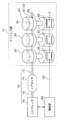
- FIG. 1 is a perspective view showing an outline of the configuration of a pressure control apparatus 10 for bedding according to the present embodiment.
- FIG. 2 is a schematic diagram showing a connection mode of each component of the pressure control apparatus 10 for bedding according to the present embodiment.
- the pressure control device 10 for bedding is a device that supports the user's body. As shown in FIG. 1, the bedding pressure control apparatus 10 according to the present embodiment includes a mattress unit 12 and an air supply unit 70. In the present embodiment, the bedding pressure control apparatus 10 further includes an operation unit 80, a headboard 16, and an arrangement specifying unit 90.
- the mattress portion 12 is a mattress-like portion that supports the user's body.
- the mattress unit 12 includes a plurality of control circuits 60 and a plurality of pressure units 20 as shown in FIG. Further, in the present embodiment, as shown in FIG. 1, the mattress unit 12 further includes a cover 14 that covers the plurality of pressure units 20 and the plurality of control circuits 60.
- the plurality of control circuits 60 are circuits that are connected in a daisy chain and perform parallel computing, and control the driving of the pressure unit 20.
- the detailed configuration of each control circuit 60 will be described later.
- the plurality of pressurizing units 20 are devices that are respectively controlled by the plurality of control circuits 60 and apply pressure to the user's body.
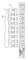
- the pressurizing unit 20 is arranged in a 40 ⁇ 20 matrix, for example. As shown in FIG. 2, the pressurizing unit 20 includes an air ball 30, an air pressure adjusting unit 40, a linear actuator 50, and a control circuit 60. The detailed configuration of each pressure unit 20 will be described later.
- the cover 14 shown in FIG. 1 is a bag-like member that covers the plurality of pressure units 20.
- the material of the cover 14 is not particularly limited.
- a material of the cover 14 for example, a polyester-based synthetic fiber can be used.
- the air supply unit 70 shown in FIGS. 1 and 2 is a device that supplies air (air) to the air ball 30 and the air pressure adjustment unit 40 of each of the plurality of pressurizing units 20.
- the configuration of the air supply unit 70 is not particularly limited as long as air can be supplied. Further, the air supply unit 70 may supply a gas such as nitrogen other than air.
- the air supply unit 70 includes a compressor 76, an air tank 74, and hoses 72 and 75.
- the compressor 76 shown in FIGS. 1 and 2 is a device that supplies pressurized air to the plurality of pressurizing units 20.
- the air discharged from the compressor 76 is supplied to the air tank 74 via the hose 75.
- the configuration of the compressor 76 is not particularly limited. Any known compressor can be used as the compressor 76.
- the air tank 74 shown in FIGS. 1 and 2 is a tank that temporarily stores the air discharged from the compressor 76.
- the air tank 74 has a function as a buffer for suppressing the pressure fluctuation of the air discharged from the compressor 76 from being transmitted to the pressurizing unit 20, and also has a function of storing the pressurized air.
- air can be stored in the air tank 74 by driving the compressor 76 before using the bedding pressure control device 10.
- the pressure applied to the body by the pressurizing unit 20 can be adjusted by stopping the compressor 76 and supplying the air stored in the air tank 74 to the pressurizing unit 20. .
- the compressor 76 can be stopped when using the pressure control apparatus 10 for bedding, noise caused by the compressor 76 can be reduced.
- the material of the hose 72 is not particularly limited. As the hose 72, any known hose suitable for air pressure can be used.
- the hose 75 shown in FIGS. 1 and 2 is a hose for supplying air from the compressor 76 to the air tank 74.
- the configuration of the hose 75 is the same as that of the hose 72.
- the operation unit 80 shown in FIGS. 1 and 2 is a device for operating the pressure control device 10 for bedding. As shown in FIG. 2, the operation unit 80 is connected to the control circuit 60 by an electric wire 82. In the present embodiment, as shown in FIG. 1, the operation unit 80 includes a display unit 84 that is a user interface and an operation button 86 that is an input unit.
- the functional configuration of the operation unit 80 will be described with reference to FIG. 3 in addition to FIGS. 1 and 2.
- FIG. 3 is a block diagram showing a functional configuration of the operation unit 80 according to the present embodiment. 3 also shows a control circuit 60 and a compressor 76 operated by the operation unit 80, and an arrangement specifying unit 90 that outputs a signal to the operation unit 80.
- the operation unit 80 functionally includes an input unit 85, a display unit 84, an operation unit control circuit 88, and a communication unit 89.
- the input unit 85 is a functional unit for a user to input an operation signal.
- the input unit 85 includes a plurality of operation buttons 86 shown in FIG.
- the display unit 84 is a user interface that displays an operation status and the like.
- the display unit 84 is composed of, for example, a liquid crystal panel.
- the operation unit control circuit 88 is a processing unit that generates an image signal based on an operation signal input by the user using the input unit 85 and transmits the image signal to the display unit 84.
- the operation unit control circuit 88 generates a control signal to be transmitted to each of the compressor 76 and the control circuit 60 based on the operation signal, and transmits the control signal to the communication unit 89.
- the communication unit 89 is a processing unit that transmits the control signal transmitted from the operation unit control circuit 88 to the compressor 76, the control circuit 60, and the arrangement specifying unit 90.
- Each processing unit of the operation unit 80 is realized by, for example, a microcomputer including a program, a memory, and a processor.
- the operation unit 80 Since the operation unit 80 is configured as described above, the user can operate the bedding pressure control apparatus 10 by pressing the operation button 86.
- the headboard 16 shown in FIG. 1 is a plate-like member disposed at the end of the mattress portion 12 in the longitudinal direction.
- the material of the head board 16 is not particularly limited.
- an arrangement specifying unit 90 is arranged on the headboard 16.
- the arrangement specifying unit 90 is a processing unit that specifies the arrangement of the user's body.
- the arrangement specifying unit 90 includes an imaging unit 92, and pressurization corresponding to each part of the body among the plurality of pressurization units 20 based on the user's body imaged by the imaging unit 92 and the image of the mattress unit 12.
- the part 20 is specified.
- the arrangement specifying unit 90 will be described with reference to the drawings.
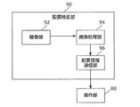
- FIG. 4 is a block diagram showing a functional configuration of the arrangement specifying unit 90 according to the present embodiment.
- the operation unit 80 is also shown together with the arrangement specifying unit 90.
- the arrangement specifying unit 90 functionally includes an imaging unit 92, an image processing unit 94, and an arrangement information communication unit 96.
- the imaging unit 92 is a camera that captures images of the user's body and the mattress unit 12.
- the image processing unit 94 is a processing unit that identifies the pressing unit 20 corresponding to each part of the body among the plurality of pressing units 20 based on the image captured by the imaging unit 92.
- the image processing unit 94 includes arrangement information of each pressing unit 20 in the mattress unit 12 in advance.
- the image processing unit 94 detects that the user's body exists on the mattress unit 12 by performing image processing, the image processing unit 94 indicates the correspondence between the position of each part of the body and the position of each pressurizing unit 20. Arrangement information is generated, and the arrangement information is transmitted to the arrangement information communication unit 96.
- the arrangement information communication unit 96 is a processing unit that transmits the arrangement information transmitted from the image processing unit 94 to the operation unit 80.
- Each processing unit of the arrangement specifying unit 90 is realized by, for example, a microcomputer including a program, a memory, and a processor.
- the arrangement information transmitted from the arrangement specifying unit 90 may be directly transmitted to the control circuit 60 without passing through the operation unit 80.
- FIG. 5 is a side view showing an appearance of the pressurizing unit 20 according to the present embodiment.
- FIG. 6 is an exploded perspective view showing the configuration of the pressure unit 20 according to the present embodiment.
- FIG. 7 is a cross-sectional view showing the configuration of the pressure unit 20 according to the present embodiment.
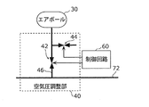
- FIG. 8 is a piping diagram showing a schematic configuration of the air pressure adjusting unit 40 according to the present embodiment.
- the pressurizing unit 20 includes the air ball 30, the air pressure adjusting unit 40, and the linear actuator 50 as described above.
- the pressurizing unit 20 further includes a pressure sensor 18 and a vibration sensor 19.
- the air ball 30 is a bag-like member arranged at the end of the pressurizing unit 20 on the body side of the user.
- a vent 32 is formed in the air ball 30. Air having a pressure adjusted by the air pressure adjusting unit 40 is sealed from the vent 32. Accordingly, the pressure control device 10 for bedding supports the body with the elastic air ball 30, and therefore, when the body abuts on the pressure control device 10 for bedding, both the body and the pressure unit 20 are supported. The applied impact can be reduced.
- the material of the air ball 30 is not particularly limited as long as the material can ensure airtightness.
- the air ball 30 can be formed of a laminated material including, for example, vinyl chloride.
- the air pressure adjusting unit 40 is a device that adjusts the pressure of the air sealed in the air ball 30. High pressure air is supplied from the hose 72 to the air pressure adjusting unit 40. The air pressure adjusting unit 40 receives a control signal from the control circuit 60 and adjusts the pressure of air sealed in the air ball 30 based on the control signal. As shown in FIG. 8, the air pressure adjusting unit 40 includes a hose 46, a pressurizing valve 42, and a pressure reducing valve 44.
- the hose 46 is a hose connected to the hose 72 and the air ball 30, and air is supplied from the hose 72 to the air ball 30 via the hose 46.
- the material of the hose 46 is not particularly limited.
- any known hose suitable for the pressure of air can be used.
- the pressurizing valve 42 is an electromagnetic valve for increasing the pressure of air sealed in the air ball 30.
- the pressurizing valve 42 is inserted into the hose 46 and opened and closed based on a control signal from the control circuit 60. In the present embodiment, by opening the pressurizing valve 42, air is supplied from the hose 72 to the air ball 30, and the pressure of the air enclosed in the air ball 30 increases. Further, by closing the pressurizing valve 42, the supply of air from the hose 72 to the air ball 30 is stopped, and the pressure of the air sealed in the air ball 30 is maintained.
- the pressure reducing valve 44 is an electromagnetic valve for reducing the pressure of air sealed in the air ball 30.
- the pressure reducing valve 44 is attached to a portion of the hose 46 between the pressurizing valve 42 and the air ball 30, and is opened and closed based on a control signal from the control circuit 60. In the present embodiment, by opening the pressure reducing valve 44, air is discharged from the hose 46 to the outside, and the pressure of the air sealed in the air ball 30 is reduced. Further, the pressure of the air enclosed in the air ball 30 is maintained by closing the pressure reducing valve 44.
- the linear actuator 50 is a device that adjusts the position of the end of the pressing unit 20 on the body side of the user.
- the linear actuator 50 can support the user's body with a stronger force than the air ball 30. That is, the position holding force of the body side end of each pressurizing unit 20 can be improved by the linear actuator 50.
- the linear actuator 50 includes a ball screw 51, a first gear 52, a bearing 53, a spacer 54, a second gear 55, and a motor 56.
- the ball screw 51 is a substantially rod-shaped part in which a thread is formed.
- the ball screw 51 has a disk-like portion that is attached to the air pressure adjusting unit 40.
- the ball screw 51 is attached to the air pressure adjustment unit 40 and moves integrally with the air pressure adjustment unit 40 in the vertical direction of FIG. 5 as the first gear 52 rotates.
- the pressurizing unit 20 includes a regulating unit that regulates the ball screw 51 from rotating as the first gear 52 rotates.
- the restriction portion may be provided in the spacer 54.
- the restricting portion may be a fixing member that fixes the air ball 30 to the cover 14. In this case, the rotation of the air pressure adjusting unit 40 and the ball screw 51 fixed to the air ball 30 is restricted by fixing the air ball 30 to the cover 14.
- a bolt may be used as the ball screw 51.
- the first gear 52 is a component that moves the ball screw 51 in the vertical direction of FIG.
- the first gear 52 rotates in accordance with the rotation of the second gear 55, thereby moving the ball screw 51 whose rotation is restricted in the vertical direction.
- the bearing 53 is a component for reducing the frictional resistance between the first gear 52 and the spacer 54.
- the bearing 53 is a ball bearing including a first plate 53a, balls 53b, and a second plate 53c, as shown in FIG.
- the first plate 53a and the second plate 53c are fixed to the first gear 52 and the spacer 54, respectively.
- the ball 53b is disposed in an annular groove formed in each of the first plate 53a and the second plate 53c. Thereby, the frictional resistance between the 1st board 53a and the 2nd board 53c can be reduced.
- the spacer 54 is a component for suppressing interference between the ball screw 51 and other members. As shown in FIGS. 5 to 7, the spacer 54 is a cylindrical member, and the ball screw 51 enters and leaves the space inside the spacer 54.
- the second gear 55 is a component that transmits the power of the motor 56 to the first gear 52.
- the second gear 55 is attached to the shaft of the motor 56.
- the teeth of the second gear 55 are meshed with the teeth of the first gear 52.
- the first gear 52 rotates as the second gear 55 rotates.
- the motor 56 is a device that rotates the second gear 55.
- the main body of the motor 56 is fixed to the spacer 54, for example. Thereby, only the shaft rotates without rotating the main body of the motor 56.
- the driving of the motor 56 is controlled by the control circuit 60.
- each part which comprises the linear actuator 50 is not specifically limited, For example, metals, such as stainless steel and aluminum, can be used.
- the pressure sensor 18 is a sensor that detects the pressure applied to the pressurizing unit 20.
- the pressure applied to the pressurizing unit 20 corresponds to the pressure applied to the user's body by the pressurizing unit 20. Therefore, the pressure sensor 18 can detect the pressure applied by the pressurizing unit 20 to the user's body.
- the control circuit 60 controls the pressurizing unit 20 based on the detection value of the pressure sensor 18 so that a desired pressure can be applied to the user's body. Moreover, a user's weight can be measured using the detection value of the some pressure sensor 18.
- the sensor used as the pressure sensor 18 is not particularly limited. For example, a strain sensor can be used as the pressure sensor 18.
- the vibration sensor 19 is a sensor that detects the vibration of the pressure unit 20. Since the vibration of the user's body is transmitted to the pressure unit 20, the vibration of the user's body can be detected by the vibration sensor 19.
- the vibration sensor 19 has such a high sensitivity that it can detect the heart rate and respiration rate per unit time of the user.
- the heart rate and respiration rate detected by the vibration sensor 19 are determined by the control circuit 60 to which the output signal of the vibration sensor 19 is input (that is, the control circuit 60 that controls the pressurizing unit 20 including the vibration sensor 19). Broadcast to all the control circuits 60.
- the sensor used as the vibration sensor 19 is not particularly limited. As the vibration sensor 19, for example, a piezoelectric element or the like can be used.
- control circuit 60 [3. Control circuit] Next, the control circuit 60 according to the present embodiment will be described in detail with reference to the drawings.
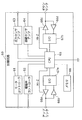
- FIG. 9 is a schematic circuit diagram showing a configuration of the control circuit 60 according to the present embodiment.
- FIG. 10 is a schematic diagram showing a connection mode of the control circuit 60 according to the present embodiment.
- the control circuit 60 is a circuit that is connected in a daisy chain and performs parallel computing, and controls the driving of the pressure unit 20. As shown in FIG. 9, the control circuit 60 includes a motor controller 61, a solenoid valve controller 62, a pressure sensor amplifier 63, a vibration sensor amplifier 64, a CPU (Central Processing Unit) 65, and buffers 66a to 66d. , Input / output units (I / O) 67a and 67b, and a memory 68.
- I / O Input / output units
- the motor controller 61 is a driver that drives the motor 56 of the linear actuator 50.
- the motor controller 61 drives the motor 56 based on a control signal input from the CPU 65.
- the electromagnetic valve controller 62 is a driver that drives the pressurizing valve 42 and the pressure reducing valve 44 of the air pressure adjusting unit 40.
- the electromagnetic valve controller 62 drives the pressurizing valve 42 and the pressure reducing valve 44 based on a control signal input from the CPU 65.
- the pressure sensor amplifier 63 is an amplifier that amplifies the signal input from the pressure sensor 18 and outputs the amplified signal to the CPU 65.
- the vibration sensor amplifier 64 is an amplifier that amplifies the signal input from the vibration sensor 19 and outputs the amplified signal to the CPU 65.
- the CPU 65 is a processor that performs an operation based on a signal input to the control circuit 60.
- Buffers 66a and 66c are storage media that temporarily store signals output from input / output units 67a and 67b, respectively.
- the buffers 66a and 66c are three-state buffers, and are switched between a high impedance (Hi-Z) on state and a high impedance off state by the CPU 65.
- the buffer 66a is maintained in a high impedance off state when a signal is output from the control circuit 60 to the control circuit 60 connected to the uplink side, and is maintained in a high impedance on state at other times.
- the uplink side means the operation unit 80 side with respect to the control circuit 60 in a signal transmission path including a plurality of control circuits 60 connected in a daisy chain.
- the buffer 66c is also maintained in a high impedance off state when a signal is output from the control circuit 60 to the control circuit 60 connected to the downlink side, and in other cases, the high impedance It remains on.
- the downlink side means a side opposite to the operation unit 80 with respect to the control circuit 60 in a signal transmission path including a plurality of control circuits 60 connected in a daisy chain.
- Buffers 66b and 66d are storage media that temporarily store signals input from the uplink side and the downlink side, respectively.
- the buffers 66b and 66d output the input signals to the input / output units 67a and 67b, respectively.
- the input / output unit 67a is a processing unit that outputs a signal output from the CPU 65 to the buffer 66a and outputs a signal input from the buffer 66b to the CPU 65.
- the input / output unit 67b is a processing unit that outputs a signal output from the CPU 65 to the buffer 66c and outputs a signal input from the buffer 66d to the CPU 65.
- the memory 68 is a storage unit in which data used for calculation in the CPU 65 is stored.
- the control circuit 60 can control the driving of the motor 56, the pressurizing valve 42, and the pressure reducing valve 44 of the pressurizing unit 20 based on the output signals of the pressure sensor 18 and the vibration sensor 19 by providing the configuration as described above. .
- the control circuit 60 is daisy chain connected as shown in FIG.
- a control circuit 60 s shown in FIG. 10 is a control circuit arranged at one end of a plurality of control circuits 60 connected in a daisy chain, and a control signal is input from the operation unit 80.
- the control circuit 60e at the right end shown in FIG. 10 is a control circuit at the end on the downlink side.
- the electric wire used for daisy chain connection may be a single electric wire. That is, the plurality of control circuits 60, 60s, and 60e may be daisy chain connected by, for example, a single core electric wire. Thereby, the weight and cost of the electric wire used for daisy chain connection can be suppressed.
- FIG. 11 is a schematic diagram showing a state of the pressurizing unit 20 before performing the pressure equalizing operation in the bedding pressurization control apparatus 10 according to the present embodiment.
- FIG. 12 is a schematic diagram illustrating a state of the pressurizing unit 20 after performing a pressure equalizing operation in the bedding pressurization control apparatus 10 according to the present embodiment.
- the user's body 200 is placed on the mattress unit 12 before performing the pressure equalization operation.
- the body 200 is supported by nine pressurizing units with pressurizing unit numbers 1 to 9.
- the actuator position of each pressurizing unit 20 (that is, the position of the body 200 side end of the linear actuator 50) is the initial value ( ⁇ 0).
- the pressure applied to each part of the body 200 in the example shown in FIG. 11 is the same as the pressure applied to each part of the body 200 in a normal bedding. Therefore, in a normal bedding, pressure concentrates on the convex part of the body 200, and a load is applied to the part.
- the linear actuator 50 of each pressurizing unit 20 is driven so that each pressurizing unit 20 corresponds to each part of the body 200.
- the pressure applied to is made uniform.
- the actuator position is raised in the pressurizing unit 20 disposed at a position corresponding to the concave portion of the body 200 (for example, the pressurizing unit numbers 2, 7, and 8).
- the pressurization part 20 arrange
- the pressure value applied to the pressurizing unit 20 by the pressure sensor 18 (that is, the pressure value applied to the body 200) is detected, and the total value of the pressure values detected by each pressurizing unit 20 is calculated. calculate. Since the total value is a value corresponding to the weight of the body 200, the total value may be hereinafter referred to as “total weight”. Subsequently, an average pressure value that is an average value of pressure values applied to each pressurizing unit 20 is calculated by dividing the total body weight by the number of pressurizing units 20 on which a part of the body 200 is placed.
- the number of the pressure parts 20 on which a part of the body 200 is placed is a value corresponding to the area where the body 200 is in contact with the mattress part 12, the number of the pressure parts 20 is hereinafter referred to as "total area”. " Then, by driving the linear actuator 50 of each pressurizing unit 20, the pressure value applied to each pressurizing unit 20 is brought close to the average pressure value. In this way, the pressure equalizing operation is performed by the pressure control device 10 for bedding. In the example shown in FIG. 12, the example in which only the linear actuator 50 is driven is shown, but the air pressure adjusting unit 40 may also be driven.
- the control circuit 60 outputs a signal input from another control circuit 60, 60s or 60e connected to the uplink side and the downlink side in the traveling direction of the signal.
- the control circuit 60 outputs a signal input from the control circuit 60 (or control circuit 60s) on the uplink side to the control circuit 60 (or control circuit 60e) on the downlink side.
- the control circuit 60 outputs a signal input from the control circuit 60 (or control circuit 60e) on the downlink side to the control circuit 60 (or control circuit 60s) on the uplink side.
- the downlink-side end control circuit 60e When receiving a signal from the uplink-side control circuit 60, the downlink-side end control circuit 60e outputs the signal to the uplink-side.
- the signal is propagated to each control circuit 60. Further, when a signal from the control circuit 60 on the downlink side is input, the control circuit 60s on the uplink side end does not output the signal. Thus, when a signal is input to the control circuit 60s from the downlink side, signal propagation stops.
- control circuit 60s and the control circuit 60e differ from the control circuit 60 in some functions. For this reason, the configurations of the control circuit 60s and the control circuit 60e are partially different.
- the control circuit 60s and the control circuit 60e can be realized by partially changing the processing in the CPU 65 of the control circuit 60. Therefore, the control circuit 60 may be provided with switching means such as a jumper pin for changing the setting so as to function as the control circuit 60s or the control circuit 60e.
- switching means such as a jumper pin for changing the setting so as to function as the control circuit 60s or the control circuit 60e.
- the initialization operation of the control circuits 60, 60s and 60e is performed using the basic operation by the control circuits 60, 60s and 60e described above.
- a reset signal is input from the operation unit 80 to the control circuit 60s at the uplink side end.
- Each of the control circuits 60, 60 s and 60 e resets values such as the total weight stored in the memory 68 when a reset signal is input. That is, all values such as total weight are set to zero.
- the total weight and the like stored in all the control circuits 60, 60s and 60e The value is reset.
- a trigger signal for starting the pressure equalization operation is generated in the control circuit 60s at the end portion on the uplink side.
- the trigger signal may be periodically generated in the control circuit 60s.
- signals indicating the total weight and total area are transmitted from the control circuit 60s to the control circuits 60 and 60e on the downlink side.
- the control circuit 60 performs an operation different from the basic operation.
- the operation when a signal indicating the total weight is input to the control circuit 60 will be described in detail with reference to the drawings.
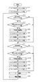
- FIG. 13 is a flowchart showing a control procedure in the pressure equalizing operation of the control circuit 60 according to the present embodiment.
- the CPU 65 of the control circuit 60 maintains the uplink-side buffer 66a in a high impedance on (Hi-Z on) state (S11). Further, the CPU 65 maintains the downlink-side buffer 66c in a high impedance on (Hi-Z on) state (S12). As a result, no signal is output from the control circuit 60.
- the CPU 65 determines whether or not a signal indicating the total weight and the total area is received at the input / output unit 67b on the downlink side (S21).
- Step S31 described later is performed.
- the CPU 65 determines whether there is an error in the signal (S22).
- the presence or absence of an error in the signal indicating the total weight may be determined using an error detection code such as a checksum. If the CPU 65 determines that there is an error in the signal (Yes in S22), step S31 described later is performed. On the other hand, when the CPU 65 determines that there is no error in the signal (No in S22), the average pressure value is calculated (S50).
- FIG. 14 is a flowchart showing a control procedure in the average pressure value calculating operation of the control circuit 60 according to the present embodiment.
- the control circuit 60 when calculating the average pressure value, first, it is determined whether the detected value (that is, the pressure value) of the pressure sensor 18 in the pressurizing unit 20 controlled by the control circuit 60 is greater than a predetermined value. (S51).
- the predetermined value is a detection value output from the pressure sensor 18 when the body 200 is not placed on the pressurizing unit 20. Thereby, it can be determined whether or not a part of the body 200 is placed on the pressurization unit 20, that is, whether or not the pressurization unit 20 applies pressure to the body 200.
- the CPU 65 backs up the area addition amount for calculating the area where the body 200 is in contact with the mattress part 12 as zero (S57), and FIG. Return to the pressure equalization operation shown.
- the CPU 65 performs area addition (S52). Specifically, the CPU 65 adds 1 to the received total area (area_rec) and subtracts the previously added area addition amount (area_bk) stored in the memory 68 to obtain the updated total area (area_data). calculate.
- the total area is calculated as the number of the pressurizing units 20 on which a part of the body 200 is placed.
- the CPU 65 backs up the area addition amount as 1 (S53).
- the control circuit 60 first performs area addition, zero is stored in the memory 68 as the area addition amount.
- the CPU 65 performs weight addition (S54). Specifically, the CPU 65 adds the pressure value (pres) to the received total body weight (weight_rec), and subtracts the weight addition amount (pres_bk) that is the previously added pressure value stored in the memory 68. Calculate the calculated total body weight (weight_data).
- the CPU 65 backs up the weight addition amount (S55).
- the control circuit 60 performs weight addition for the first time, zero is stored in the memory as the area addition amount.
- the CPU 65 calculates an average pressure value (S56). Specifically, the CPU 65 calculates the average pressure value (pres_ave) by dividing the total body weight (weight_data) by the total area (area_data). And it returns to pressure equalization operation.
- the CPU 65 switches the uplink-side buffer 66a to a high impedance off (Hi-Z off) state (S23).
- the CPU 65 transmits a signal indicating data of the calculated total weight and total area to the control circuit 60 (or control circuit 60s) on the uplink side (S24).
- the CPU 65 switches the uplink-side buffer 66a to a high impedance on (Hi-Z on) state (S25).
- the CPU 65 determines whether or not a signal indicating the total weight and the total area has been received at the uplink input / output unit 67a (S31).
- step S41 described later is performed.
- the CPU 65 determines whether there is an error in the signal (S32). If the CPU 65 determines that there is an error in the signal (Yes in S32), step S41 described later is performed.
- the CPU 65 determines that there is no error in the signal (No in S32), the average pressure value is calculated (S150).
- step S150 for calculating the average pressure value is the same as step S50 described above, description thereof is omitted.
- step S150 the CPU 65 switches the downlink side buffer 66c to a high impedance off (Hi-Z off) state (S33).
- the CPU 65 transmits a signal indicating the calculated total weight and total area data to the control circuit 60 (or control circuit 60e) on the downlink side (S34).
- the CPU 65 switches the downlink side buffer 66c to a high impedance on (Hi-Z on) state (S35).
- the CPU 65 drives the motor 56 of the pressurizing unit 20 based on the calculated average pressure value and the pressure value detected by the pressure sensor 18 (S41). Specifically, a control signal is output to the motor controller 61 so that the difference between the pressure value detected by the pressure sensor 18 and the average pressure value approaches zero. For example, when the pressure value detected by the pressure sensor 18 is smaller than the average pressure value, the CPU 65 outputs a control signal for moving the linear actuator 50 upward to the motor controller 61. The amount of movement of the linear actuator 50 can be appropriately calculated based on the difference between the pressure value detected by the pressure sensor 18 and the average pressure value.
- the CPU 65 drives the motor 56 that drives the electromagnetic valves (the pressurizing valve 42 and the pressure reducing valve 44) of the pressurizing unit 20 based on the calculated average pressure value and the like (S42). Specifically, for example, a control signal is output to the solenoid valve controller 62 so that the pressure value and the average pressure value detected by the pressure sensor 18 are lower than the air pressure in the air ball 30. When the pressure value detected by the pressure sensor 18 is relatively high, the CPU 65 outputs a control signal for opening the pressurizing valve 42 to the electromagnetic valve controller 62. Thereby, it can reduce that the air ball 30 is crushed by the body 200, and a buffer function is impaired.
- control circuit 60 can perform the pressure equalizing operation.
- the output signal of the control circuit 60 becomes the input signal of the adjacent control circuit 60, 60s or 60e. That is, the plurality of control circuits 60, 60s, and 60e perform so-called pipeline processing. As a result, the total body weight of the body 200 can be calculated.
- an operation for preventing pressure sores can be performed.
- the operation is an operation in which each of the plurality of pressurizing units 20 varies the pressure applied to the body 200 over time.
- each control circuit 60, 60 s and 60 e has a coordinate value indicating the physical position of the corresponding pressure unit 20.
- the operation unit 80 transmits a signal indicating the coordinate value and a time when a predetermined pressure is applied to the body by the pressurizing unit 20 corresponding to the coordinate value to the control circuit 60s.
- the signal is propagated to the control circuit corresponding to the coordinate value, and the control circuit corresponding to the coordinate value controls the pressurizing unit 20 according to the signal.
- the operation unit 80 can temporally vary the part of the body 200 to which a strong pressure is applied by the pressurization unit 20 by propagating the signal to the plurality of control circuits 60, 60s, and 60e. Thereby, the pressure ulcer produced in the body 200 can be suppressed.
- massage can be performed in the pressure control device 10 for bedding.
- the outline of the operation is the same as the pressure ulcer prevention operation described above, but the arrangement information from the arrangement specifying unit 90 can be used to massage a predetermined part of the body 200.
- the pressurizing unit 20 and the control circuit 60, 60s, or 60e corresponding to the waist of the body 200 are specified, and the pressurizing unit 20 applies time-varying pressure to the waist of the body 200. By applying, the waist can be massaged.
- the pressure control apparatus 10 for bedding can apply time-varying pressure to a specific part of the body, and thus, for example, lymph massage can be performed.
- the bedding pressure control device 10 can also perform an operation corresponding to a user who needs a massage of a specific part such as an athlete.
- the bedding pressure control device 10 can apply a weak pressure to each part of the body 200 in a slow rhythm, thereby performing an operation that encourages the user to sleep well.
- the arrangement specifying unit 90 is not an essential component.
- the pressure control apparatus 10 for bedding may not include the arrangement specifying unit 90 when arrangement information of the body 200 is unnecessary.
- the arrangement of the plurality of pressure units 20 is not limited to a matrix.
- a honeycomb shape may be used. By disposing the plurality of pressurizing units 20 in a honeycomb shape, the plurality of pressurizing units 20 can be arranged more densely, so that a more precise pressurizing operation can be performed.
- the shape of the air ball 30 is a barrel shape, but other shapes may be used.
- various shapes such as a sphere, a cube, and a hexagonal column can be used.
- the plurality of air balls 30 can be densely arranged by making the shape of the air balls 30 substantially hexagonal columns.
- the pressure control device 10 for bedding always measures a change in weight applied to each pressurizing unit 20 by the pressure sensor 18 included in each pressurizing unit 20, and performs posture control based on the measurement data. It is a system to do. For this reason, the pressure sensor 18 also includes weighted changes to the load pressurizing unit 20 due to the user's breathing and heartbeat in the measurement data. By calculating the measurement data, it is possible to detect not only the weight and weighted balance but also the respiration rate and heart rate per unit time. That is, each of the plurality of control circuits 60 can detect the user's respiration rate information based on the detection result of the pressure sensor 18. Therefore, the user's sleep apnea can be detected using this respiration rate information.
- each of the plurality of control circuits 60 applies a pressure applied to the user's body by at least one of the plurality of pressurizing units 20 when detecting that the user is in an apnea state based on the respiration rate information. It may be varied. For example, when the bedding pressurization control device 10 detects that the user is in an apnea state, the control circuit 60 may change the pressure of the air ball 30 abruptly. Thereby, the user can be awakened and respiration can be resumed. Further, by using the heart rate information, the bedding pressurization control device 10 can record arrhythmia, issue an alarm when detecting cardiac arrest, and the like.
- a temperature sensor may be attached to the surface of the plurality of air balls 30 on the body 200 side to measure the temperature of each part of the body.
- a temperature sensor may be attached to the surface of the plurality of air balls 30 on the body 200 side to measure the temperature of each part of the body.
- the pressurizing unit 20 includes the air ball 30 and the linear actuator 50, but may include only one of them.
- a cushioning material may be inserted between the pressure unit 20 and the cover 14.
- the present invention can be used as bedding that can adjust the pressure applied to the body, bedding that can massage the body, and the like.
Landscapes
- Invalid Beds And Related Equipment (AREA)
Abstract
Provided is a pressure application control device for bedding (10) which supports a user's body (200), said device comprising: a plurality of control circuits (60) which are connected in a daisy chain and which carry out parallel computing; and a plurality of pressure application parts (20) which are respectively controlled by the plurality of control circuits (60) and which impart pressure to the body (200).
Description
本発明は、ユーザの身体を支持する寝具用加圧制御装置に関する。
The present invention relates to a pressure control device for bedding that supports a user's body.
従来、ユーザの身体の各部位に圧力を加えることにより、マッサージなどを行う加圧可能な寝具が知られている(例えば、特許文献1)。
2. Description of the Related Art Conventionally, a pressurizable bedding that performs massage or the like by applying pressure to each part of a user's body is known (for example, Patent Document 1).
特許文献1に開示された寝具では、マトリクス状に配置された複数のアクチュエータと、複数のアクチュエータを集中制御する制御装置とを備える。特許文献1に開示された寝具では、複数のアクチュエータの各々を制御することによって、身体の各部位に所定の圧力を加えようとしている。
The bedding disclosed in Patent Document 1 includes a plurality of actuators arranged in a matrix and a control device that centrally controls the plurality of actuators. In the bedding disclosed in Patent Document 1, a predetermined pressure is applied to each part of the body by controlling each of the plurality of actuators.
しかしながら、特許文献1に開示された寝具では、多数のアクチュエータを身体の動きなどに応じて速やかに制御するために、制御装置には高い処理能力が要求される。そのため、制御装置に要するコストが高い。また、制御装置が多数のアクチュエータの各々を制御するために、制御装置と各アクチュエータとを通信ケーブルで接続する必要がある。このように、特許文献1に開示された寝具では通信ケーブルを大量に用いているため、寝具の重量が大きくなり、取り扱いが困難である。また、通信ケーブルに要するコストも高い。
However, in the bedding disclosed in Patent Document 1, a high processing capability is required for the control device in order to quickly control a large number of actuators according to the movement of the body. Therefore, the cost required for the control device is high. Further, in order for the control device to control each of a large number of actuators, it is necessary to connect the control device and each actuator with a communication cable. Thus, since the bedding disclosed in Patent Document 1 uses a large amount of communication cables, the weight of the bedding increases, making it difficult to handle. Moreover, the cost required for the communication cable is high.
そこで、本発明は、ユーザの身体の各部位に圧力を加える寝具用加圧制御装置であって、軽量で、かつ、低コストである寝具用加圧制御装置を提供することを目的とする。
Therefore, an object of the present invention is to provide a pressure control device for bedding that applies pressure to each part of a user's body, and is lightweight and low-cost.
上記課題を解決するために、本発明の一態様に係る寝具用加圧制御装置は、ユーザの身体を支持する寝具用加圧制御装置であって、デイジーチェーン接続され、並列コンピューティングを行う複数の制御回路と、前記複数の制御回路によってそれぞれ制御され、前記身体に圧力を加える複数の加圧部とを備える。
In order to solve the above-described problem, a pressure control device for bedding according to an aspect of the present invention is a pressure control device for bedding that supports the body of a user, and is a plurality of daisy chain connected and parallel computing devices. And a plurality of pressurizing units that are respectively controlled by the plurality of control circuits and apply pressure to the body.
これによれば、複数の加圧部の各々が、複数の制御回路のうち当該加圧部に対応する一つの制御回路によって制御されるため、複数の加圧部を集中制御するための制御装置が不要である。また、各制御回路に接続される通信用の電線は、デイジーチェーン接続のための電線だけでよい。したがって、電線に要するコスト、及び、寝具用加圧制御装置の重量を抑制することができる。また、各制御回路は、一つの加圧部だけを制御すればよい。したがって、各制御回路の処理負荷は小さいため、各制御回路に要求される処理能力を低減できる。このため、制御回路に要するコストを抑制できる。
According to this, since each of the plurality of pressurizing units is controlled by one control circuit corresponding to the pressurizing unit among the plurality of control circuits, the control device for centrally controlling the plurality of pressurizing units. Is unnecessary. Further, the communication wires connected to each control circuit need only be wires for daisy chain connection. Therefore, the cost required for the electric wires and the weight of the pressure control device for bedding can be suppressed. Each control circuit only needs to control one pressurizing unit. Therefore, since the processing load of each control circuit is small, the processing capability required for each control circuit can be reduced. For this reason, the cost which a control circuit requires can be suppressed.
また、本発明の一態様に係る寝具用加圧制御装置において、前記複数の制御回路は、単芯の電線によってデイジーチェーン接続されており、前記複数の制御回路の各々は、共通のグランドに接続されていてもよい。
Further, in the pressure control device for bedding according to one aspect of the present invention, the plurality of control circuits are daisy chain connected by a single-core electric wire, and each of the plurality of control circuits is connected to a common ground. May be.
これによれば、デイジーチェーン接続に用いられる電線の重量及びコストをより一層抑制できる。
According to this, the weight and cost of the wire used for daisy chain connection can be further suppressed.
また、本発明の一態様に係る寝具用加圧制御装置において、前記複数の加圧部の各々は、前記身体側の端部に配置されたエアボールを備え、前記エアボールの内部の気圧を調整してもよい。
Further, in the pressure control device for bedding according to one aspect of the present invention, each of the plurality of pressure units includes an air ball disposed at an end on the body side, and the air pressure inside the air ball is controlled. You may adjust.
これによれば、寝具用加圧制御装置は、エアボールにおいて身体を支持するため、身体が寝具用加圧制御装置に当接する際に、身体及び加圧部の双方に加わる衝撃を低減することができる。
According to this, since the pressure control device for bedding supports the body in the air ball, when the body contacts the pressure control device for bedding, the impact applied to both the body and the pressure unit is reduced. Can do.
また、本発明の一態様に係る寝具用加圧制御装置において、前記複数の加圧部にエアを供給する一本のホースをさらに備えてもよい。
In the pressure control apparatus for bedding according to an aspect of the present invention, the apparatus may further include a single hose that supplies air to the plurality of pressure units.
これによれば、一本のホースを介して複数の加圧部にエアを供給できるため、エア供給用の部品に要する重量及びコストを抑制できる。
According to this, since air can be supplied to a plurality of pressurizing parts via one hose, the weight and cost required for air supply parts can be suppressed.
また、本発明の一態様に係る寝具用加圧制御装置において、前記複数の加圧部の各々は、前記身体側の端部の位置を調整するリニアアクチュエータを備えてもよい。
Further, in the pressure control device for bedding according to one aspect of the present invention, each of the plurality of pressure units may include a linear actuator that adjusts the position of the end portion on the body side.
これによれば、各加圧部の身体側端部の位置保持力を向上させることができる。
According to this, it is possible to improve the position holding force of the body side end of each pressurizing unit.
また、本発明の一態様に係る寝具用加圧制御装置において、当該加圧部に印加される圧力を検出する圧力センサをさらに備えてもよい。
Moreover, the pressure control device for bedding according to an aspect of the present invention may further include a pressure sensor that detects a pressure applied to the pressure unit.
これによれば、圧力センサの検出値に基づいて、各加圧部に印加される圧力を調整することができる。また、複数の圧力センサの検出値を用いて、ユーザの体重を計測することができる。
According to this, the pressure applied to each pressurizing part can be adjusted based on the detection value of the pressure sensor. Moreover, a user's weight can be measured using the detection value of a some pressure sensor.
また、本発明の一態様に係る寝具用加圧制御装置において、前記複数の制御回路の各々は、前記圧力センサの検出結果に基づいて、前記ユーザの呼吸数情報を検出してもよい。
In the pressure control apparatus for bedding according to one aspect of the present invention, each of the plurality of control circuits may detect the respiration rate information of the user based on a detection result of the pressure sensor.
これによれば、ユーザの呼吸情報に基づいて、例えば、ユーザが無呼吸状態であることを検知することができる。
According to this, based on the user's breathing information, for example, it can be detected that the user is in an apnea state.
また、本発明の一態様に係る寝具用加圧制御装置において、前記複数の制御回路の各々は、前記呼吸数情報に基づいて、前記ユーザが無呼吸状態であることを検知した場合に、前記複数の加圧部の少なくとも一つによって前記身体に加える圧力を変動させてもよい。
Further, in the pressure control device for bedding according to one aspect of the present invention, when each of the plurality of control circuits detects that the user is in an apnea state based on the respiratory rate information, The pressure applied to the body may be varied by at least one of the plurality of pressurizing units.
これによれば、無呼吸状態であるユーザを覚醒させ、呼吸を再開させることができる。
According to this, the user who is in an apnea state can be awakened and respiration can be resumed.
また、本発明の一態様に係る寝具用加圧制御装置において、前記複数の制御回路の各々は、前記圧力センサの検出結果に基づいて、前記ユーザの心拍数情報を検出してもよい。
In the pressure control apparatus for bedding according to one aspect of the present invention, each of the plurality of control circuits may detect the heart rate information of the user based on a detection result of the pressure sensor.
これによれば、ユーザの心拍数情報に基づいて、例えば、ユーザの不整脈の記録、心停止検知時の警報発報を行うことができる。
According to this, based on the user's heart rate information, for example, the user's arrhythmia can be recorded and an alarm can be issued when cardiac arrest is detected.
また、本発明の一態様に係る寝具用加圧制御装置において、前記複数の制御回路は、パイプライン処理を行ってもよい。
In the pressure control apparatus for bedding according to one embodiment of the present invention, the plurality of control circuits may perform pipeline processing.
これによれば、複数の制御回路によって、例えば、圧力センサなどを用いてユーザの体重などを算出することができる。
According to this, the weight of the user can be calculated by using a plurality of control circuits using, for example, a pressure sensor.
本発明により、ユーザの身体の各部位に圧力を加える寝具用加圧制御装置であって、軽量で、かつ、低コストである寝具用加圧制御装置を提供できる。
According to the present invention, it is possible to provide a pressure control device for bedding that applies pressure to each part of the user's body, and is lightweight and low-cost.
なお、以下で説明する実施の形態は、いずれも本発明の一具体例を示すものである。以下の実施の形態で示される数値、形状、材料、構成要素、構成要素の配置位置及び接続形態、ステップ、ステップの順序などは、一例であり、本発明を限定する主旨ではない。また、以下の実施の形態における構成要素のうち、本発明の最上位概念を示す独立請求項に記載されていない構成要素については、より好ましい形態を構成する任意の構成要素として説明される。
Note that each of the embodiments described below shows a specific example of the present invention. The numerical values, shapes, materials, constituent elements, arrangement positions and connecting forms of the constituent elements, steps, order of steps, and the like shown in the following embodiments are merely examples, and are not intended to limit the present invention. In addition, among the constituent elements in the following embodiments, constituent elements that are not described in the independent claims indicating the highest concept of the present invention are described as optional constituent elements that constitute a more preferable embodiment.
なお、同一の構成要素には同一の符号を付し、説明を省略する場合がある。
In addition, the same code | symbol is attached | subjected to the same component and description may be abbreviate | omitted.
(実施の形態)
[1.全体構成]
まず、実施の形態に係る寝具用加圧制御装置の全体構成について図面を用いて説明する。 (Embodiment)
[1. overall structure]
First, the overall configuration of a pressure control device for bedding according to an embodiment will be described with reference to the drawings.
[1.全体構成]
まず、実施の形態に係る寝具用加圧制御装置の全体構成について図面を用いて説明する。 (Embodiment)
[1. overall structure]
First, the overall configuration of a pressure control device for bedding according to an embodiment will be described with reference to the drawings.
図1は、本実施の形態に係る寝具用加圧制御装置10の構成の概要を示す斜視図である。
FIG. 1 is a perspective view showing an outline of the configuration of a pressure control apparatus 10 for bedding according to the present embodiment.
図2は、本実施の形態に係る寝具用加圧制御装置10の各構成要素の接続態様を示す概略図である。
FIG. 2 is a schematic diagram showing a connection mode of each component of the pressure control apparatus 10 for bedding according to the present embodiment.
本実施の形態に係る寝具用加圧制御装置10は、ユーザの身体を支持する装置である。図1に示されるように、本実施の形態に係る寝具用加圧制御装置10は、マットレス部12と、エア供給部70とを備える。本実施の形態では、寝具用加圧制御装置10は、さらに、操作部80と、ヘッドボード16と、配置特定部90とを備える。
The pressure control device 10 for bedding according to the present embodiment is a device that supports the user's body. As shown in FIG. 1, the bedding pressure control apparatus 10 according to the present embodiment includes a mattress unit 12 and an air supply unit 70. In the present embodiment, the bedding pressure control apparatus 10 further includes an operation unit 80, a headboard 16, and an arrangement specifying unit 90.
マットレス部12は、ユーザの身体を支持するマットレス状の部分である。本実施の形態では、マットレス部12は、図2に示されるように、複数の制御回路60と、複数の加圧部20とを備える。さらに、本実施の形態では、図1に示されるように、マットレス部12は、複数の加圧部20及び複数の制御回路60を覆うカバー14をさらに備える。
The mattress portion 12 is a mattress-like portion that supports the user's body. In the present embodiment, the mattress unit 12 includes a plurality of control circuits 60 and a plurality of pressure units 20 as shown in FIG. Further, in the present embodiment, as shown in FIG. 1, the mattress unit 12 further includes a cover 14 that covers the plurality of pressure units 20 and the plurality of control circuits 60.
複数の制御回路60は、デイジーチェーン接続され、並列コンピューティングを行う回路であり、加圧部20の駆動を制御する。各制御回路60の詳細構成については後述する。
The plurality of control circuits 60 are circuits that are connected in a daisy chain and perform parallel computing, and control the driving of the pressure unit 20. The detailed configuration of each control circuit 60 will be described later.
複数の加圧部20は、複数の制御回路60によってそれぞれ制御され、ユーザの身体に圧力を加える機器である。加圧部20は、例えば、40×20のマトリクス状に配置されている。図2に示されるように、加圧部20は、エアボール30と、空気圧調整部40と、リニアアクチュエータ50と、制御回路60とを備える。各加圧部20の詳細構成については後述する。
The plurality of pressurizing units 20 are devices that are respectively controlled by the plurality of control circuits 60 and apply pressure to the user's body. The pressurizing unit 20 is arranged in a 40 × 20 matrix, for example. As shown in FIG. 2, the pressurizing unit 20 includes an air ball 30, an air pressure adjusting unit 40, a linear actuator 50, and a control circuit 60. The detailed configuration of each pressure unit 20 will be described later.
図1に示されるカバー14は、複数の加圧部20を覆う袋状の部材である。カバー14の材質は、特に限定されない。カバー14の材質としては、例えば、ポリエステル系合成繊維などを用いることができる。
The cover 14 shown in FIG. 1 is a bag-like member that covers the plurality of pressure units 20. The material of the cover 14 is not particularly limited. As a material of the cover 14, for example, a polyester-based synthetic fiber can be used.
図1及び図2に示されるエア供給部70は、複数の加圧部20の各々のエアボール30及び空気圧調整部40にエア(空気)を供給する機器である。エア供給部70の構成は、エアを供給できれば特に限定されない。また、エア供給部70がエア以外の窒素などの気体を供給してもよい。本実施の形態では、エア供給部70は、コンプレッサ76とエアタンク74とホース72及び75を備える。
The air supply unit 70 shown in FIGS. 1 and 2 is a device that supplies air (air) to the air ball 30 and the air pressure adjustment unit 40 of each of the plurality of pressurizing units 20. The configuration of the air supply unit 70 is not particularly limited as long as air can be supplied. Further, the air supply unit 70 may supply a gas such as nitrogen other than air. In the present embodiment, the air supply unit 70 includes a compressor 76, an air tank 74, and hoses 72 and 75.
図1及び図2に示されるコンプレッサ76は、加圧されたエアを複数の加圧部20に供給する機器である。本実施の形態では、コンプレッサ76から吐出されたエアは、ホース75を介してエアタンク74に供給される。コンプレッサ76の構成は特に限定されない。コンプレッサ76として、任意の公知のコンプレッサを用いることができる。
The compressor 76 shown in FIGS. 1 and 2 is a device that supplies pressurized air to the plurality of pressurizing units 20. In the present embodiment, the air discharged from the compressor 76 is supplied to the air tank 74 via the hose 75. The configuration of the compressor 76 is not particularly limited. Any known compressor can be used as the compressor 76.
図1及び図2に示されるエアタンク74は、コンプレッサ76から吐出されたエアを一時的に蓄えるタンクである。エアタンク74は、コンプレッサ76から吐出されたエアの圧力変動が加圧部20に伝わることを抑制するための緩衝器としての機能を有し、かつ、加圧されたエアを蓄える機能も有する。これにより、寝具用加圧制御装置10の使用前に、コンプレッサ76を駆動することによって、エアタンク74にエアを蓄えることができる。このため、寝具用加圧制御装置10の使用時には、コンプレッサ76を停止させ、エアタンク74に蓄えられたエアを加圧部20に供給することで、加圧部20が身体に加える圧力を調整できる。このように、寝具用加圧制御装置10の使用時にコンプレッサ76を停止させることができるため、コンプレッサ76に起因する騒音を低減することができる。
The air tank 74 shown in FIGS. 1 and 2 is a tank that temporarily stores the air discharged from the compressor 76. The air tank 74 has a function as a buffer for suppressing the pressure fluctuation of the air discharged from the compressor 76 from being transmitted to the pressurizing unit 20, and also has a function of storing the pressurized air. Thus, air can be stored in the air tank 74 by driving the compressor 76 before using the bedding pressure control device 10. For this reason, when using the pressure control device 10 for bedding, the pressure applied to the body by the pressurizing unit 20 can be adjusted by stopping the compressor 76 and supplying the air stored in the air tank 74 to the pressurizing unit 20. . Thus, since the compressor 76 can be stopped when using the pressure control apparatus 10 for bedding, noise caused by the compressor 76 can be reduced.
図1及び図2に示されるホース72は、複数の加圧部20にエアを供給する一本のホースである。本実施の形態では、すべての加圧部20が、ホース72からエアを供給される。これにより、エア供給用の部品に要する重量及びコストを抑制できる。ホース72の材質は、特に限定されない。ホース72として、エアの圧力に適した任意の公知のホースを用いることができる。
1 and 2 is a single hose that supplies air to the plurality of pressurizing units 20. In the present embodiment, all the pressurizing units 20 are supplied with air from the hose 72. Thereby, the weight and cost which an air supply component requires can be suppressed. The material of the hose 72 is not particularly limited. As the hose 72, any known hose suitable for air pressure can be used.
図1及び図2に示されるホース75は、コンプレッサ76からエアタンク74にエアを供給するためのホースである。ホース75の構成はホース72と同様である。
The hose 75 shown in FIGS. 1 and 2 is a hose for supplying air from the compressor 76 to the air tank 74. The configuration of the hose 75 is the same as that of the hose 72.
図1及び図2に示される操作部80は、寝具用加圧制御装置10を操作するための機器である。図2に示されるように、操作部80は、電線82によって制御回路60と接続されている。本実施の形態では、操作部80は、図1に示されるように、ユーザインターフェースである表示部84と、入力部である操作ボタン86を備える。以下、操作部80の機能構成について図1及び図2に加えて図3を用いて説明する。
The operation unit 80 shown in FIGS. 1 and 2 is a device for operating the pressure control device 10 for bedding. As shown in FIG. 2, the operation unit 80 is connected to the control circuit 60 by an electric wire 82. In the present embodiment, as shown in FIG. 1, the operation unit 80 includes a display unit 84 that is a user interface and an operation button 86 that is an input unit. Hereinafter, the functional configuration of the operation unit 80 will be described with reference to FIG. 3 in addition to FIGS. 1 and 2.
図3は、本実施の形態に係る操作部80の機能構成を示すブロック図である。なお、図3には、操作部80によって操作される制御回路60及びコンプレッサ76と、操作部80に信号を出力する配置特定部90も併せて示されている。
FIG. 3 is a block diagram showing a functional configuration of the operation unit 80 according to the present embodiment. 3 also shows a control circuit 60 and a compressor 76 operated by the operation unit 80, and an arrangement specifying unit 90 that outputs a signal to the operation unit 80.
図3に示されるように、操作部80は、機能的には、入力部85と、表示部84と、操作部用制御回路88と、通信部89とを備える。
As shown in FIG. 3, the operation unit 80 functionally includes an input unit 85, a display unit 84, an operation unit control circuit 88, and a communication unit 89.
入力部85は、ユーザが操作信号を入力するための機能部である。本実施の形態では、入力部85は、図1に示される複数の操作ボタン86で構成される。
The input unit 85 is a functional unit for a user to input an operation signal. In the present embodiment, the input unit 85 includes a plurality of operation buttons 86 shown in FIG.
表示部84は、操作状況などが示されるユーザインターフェースである。表示部84は、例えば、液晶パネルなどで構成される。
The display unit 84 is a user interface that displays an operation status and the like. The display unit 84 is composed of, for example, a liquid crystal panel.
操作部用制御回路88は、ユーザが入力部85を用いて入力する操作信号に基づいて、画像信号を生成して表示部84に当該画像信号を送信する処理部である。また、操作部用制御回路88は、操作信号に基づいてコンプレッサ76及び制御回路60のそれぞれに送信する制御信号を生成し、通信部89に送信する。
The operation unit control circuit 88 is a processing unit that generates an image signal based on an operation signal input by the user using the input unit 85 and transmits the image signal to the display unit 84. The operation unit control circuit 88 generates a control signal to be transmitted to each of the compressor 76 and the control circuit 60 based on the operation signal, and transmits the control signal to the communication unit 89.
通信部89は、操作部用制御回路88から送信された制御信号を、コンプレッサ76、制御回路60及び配置特定部90に送信する処理部である。
The communication unit 89 is a processing unit that transmits the control signal transmitted from the operation unit control circuit 88 to the compressor 76, the control circuit 60, and the arrangement specifying unit 90.
操作部80の各処理部は、例えば、プログラム、メモリ及びプロセッサを含むマイクロコンピュータなどで実現される。
Each processing unit of the operation unit 80 is realized by, for example, a microcomputer including a program, a memory, and a processor.
操作部80が以上のような構成を備えていることにより、ユーザは、操作ボタン86を押すことで、寝具用加圧制御装置10を操作することができる。
Since the operation unit 80 is configured as described above, the user can operate the bedding pressure control apparatus 10 by pressing the operation button 86.
図1に示されるヘッドボード16は、マットレス部12の長手方向端部に配置された板状部材である。ヘッドボード16の材質は特に限定されない。ヘッドボード16の材質として、例えば木材などを用いることができる。本実施の形態では、ヘッドボード16には配置特定部90が配置される。
The headboard 16 shown in FIG. 1 is a plate-like member disposed at the end of the mattress portion 12 in the longitudinal direction. The material of the head board 16 is not particularly limited. As a material of the headboard 16, for example, wood can be used. In the present embodiment, an arrangement specifying unit 90 is arranged on the headboard 16.
配置特定部90は、ユーザの身体の配置を特定する処理部である。配置特定部90は、撮像部92を備え、撮像部92によって撮像されたユーザの身体及びマットレス部12の画像に基づいて、複数の加圧部20のうち、身体の各部位に対応する加圧部20を特定する。ここで、配置特定部90について図面を用いて説明する。
The arrangement specifying unit 90 is a processing unit that specifies the arrangement of the user's body. The arrangement specifying unit 90 includes an imaging unit 92, and pressurization corresponding to each part of the body among the plurality of pressurization units 20 based on the user's body imaged by the imaging unit 92 and the image of the mattress unit 12. The part 20 is specified. Here, the arrangement specifying unit 90 will be described with reference to the drawings.
図4は、本実施の形態に係る配置特定部90の機能構成を示すブロック図である。なお、図4には、配置特定部90と併せて操作部80も示されている。
FIG. 4 is a block diagram showing a functional configuration of the arrangement specifying unit 90 according to the present embodiment. In FIG. 4, the operation unit 80 is also shown together with the arrangement specifying unit 90.
図4に示されるように、本実施の形態に係る配置特定部90は、機能的には、撮像部92と、画像処理部94と、配置情報通信部96とを備える。
4, the arrangement specifying unit 90 according to the present embodiment functionally includes an imaging unit 92, an image processing unit 94, and an arrangement information communication unit 96.
撮像部92は、ユーザの身体及びマットレス部12の画像を撮像するカメラである。
The imaging unit 92 is a camera that captures images of the user's body and the mattress unit 12.
画像処理部94は、撮像部92によって撮像された画像に基づいて、複数の加圧部20のうち、身体の各部位に対応する加圧部20を特定する処理部である。画像処理部94は、予めマットレス部12における各加圧部20の配置情報を備えている。画像処理部94は、画像処理を行うことによって、ユーザの身体がマットレス部12上に存在することを検知した場合、身体の各部位の位置と、各加圧部20の位置との対応を示す配置情報を生成し、当該配置情報を配置情報通信部96に送信する。
The image processing unit 94 is a processing unit that identifies the pressing unit 20 corresponding to each part of the body among the plurality of pressing units 20 based on the image captured by the imaging unit 92. The image processing unit 94 includes arrangement information of each pressing unit 20 in the mattress unit 12 in advance. When the image processing unit 94 detects that the user's body exists on the mattress unit 12 by performing image processing, the image processing unit 94 indicates the correspondence between the position of each part of the body and the position of each pressurizing unit 20. Arrangement information is generated, and the arrangement information is transmitted to the arrangement information communication unit 96.
配置情報通信部96は、画像処理部94から送信された配置情報を操作部80に送信する処理部である。
The arrangement information communication unit 96 is a processing unit that transmits the arrangement information transmitted from the image processing unit 94 to the operation unit 80.
配置特定部90の各処理部は、例えば、プログラム、メモリ及びプロセッサを含むマイクロコンピュータなどで実現される。
Each processing unit of the arrangement specifying unit 90 is realized by, for example, a microcomputer including a program, a memory, and a processor.
なお、配置特定部90から送信される配置情報は、操作部80を経由させずに制御回路60に直接送信されてもよい。
The arrangement information transmitted from the arrangement specifying unit 90 may be directly transmitted to the control circuit 60 without passing through the operation unit 80.
[2.加圧部]
次に、本実施の形態に係る加圧部20について図面を用いて詳細に説明する。 [2. Pressure unit]
Next, the pressurizingunit 20 according to the present embodiment will be described in detail with reference to the drawings.
次に、本実施の形態に係る加圧部20について図面を用いて詳細に説明する。 [2. Pressure unit]
Next, the pressurizing
図5は、本実施の形態に係る加圧部20の外観を示す側面図である。
FIG. 5 is a side view showing an appearance of the pressurizing unit 20 according to the present embodiment.
図6は、本実施の形態に係る加圧部20の構成を示す分解斜視図である。
FIG. 6 is an exploded perspective view showing the configuration of the pressure unit 20 according to the present embodiment.
図7は、本実施の形態に係る加圧部20の構成を示す断面図である。
FIG. 7 is a cross-sectional view showing the configuration of the pressure unit 20 according to the present embodiment.
図8は、本実施の形態に係る空気圧調整部40の概略構成を示す配管図である。
FIG. 8 is a piping diagram showing a schematic configuration of the air pressure adjusting unit 40 according to the present embodiment.
図5~図7に示されるように、本実施の形態に係る加圧部20は、上述のとおり、エアボール30と、空気圧調整部40とリニアアクチュエータ50とを備える。本実施の形態では、加圧部20は、さらに、圧力センサ18と、振動センサ19とを備える。
As shown in FIGS. 5 to 7, the pressurizing unit 20 according to the present embodiment includes the air ball 30, the air pressure adjusting unit 40, and the linear actuator 50 as described above. In the present embodiment, the pressurizing unit 20 further includes a pressure sensor 18 and a vibration sensor 19.
エアボール30は、加圧部20のユーザの身体側の端部に配置された袋状の部材である。エアボール30には、通気口32が形成されている。通気口32から空気圧調整部40によって調整された圧力のエアが封入される。これにより、寝具用加圧制御装置10は、弾力性のあるエアボール30において身体を支持するため、身体が寝具用加圧制御装置10に当接する際に、身体及び加圧部20の双方に加わる衝撃を低減することができる。
The air ball 30 is a bag-like member arranged at the end of the pressurizing unit 20 on the body side of the user. A vent 32 is formed in the air ball 30. Air having a pressure adjusted by the air pressure adjusting unit 40 is sealed from the vent 32. Accordingly, the pressure control device 10 for bedding supports the body with the elastic air ball 30, and therefore, when the body abuts on the pressure control device 10 for bedding, both the body and the pressure unit 20 are supported. The applied impact can be reduced.
エアボール30の材質は、気密性を確保できる材質であれば特に限定されない。エアボール30は、例えば、塩化ビニルなどを含む積層素材で形成することができる。
The material of the air ball 30 is not particularly limited as long as the material can ensure airtightness. The air ball 30 can be formed of a laminated material including, for example, vinyl chloride.
空気圧調整部40は、エアボール30に封入されるエアの圧力を調整する機器である。空気圧調整部40には、ホース72から高圧のエアが供給される。空気圧調整部40は、制御回路60からの制御信号を受信し、制御信号に基づいて、エアボール30内に封入されるエアの圧力を調整する。図8に示されるように、空気圧調整部40は、ホース46、加圧弁42と、減圧弁44とを備える。
The air pressure adjusting unit 40 is a device that adjusts the pressure of the air sealed in the air ball 30. High pressure air is supplied from the hose 72 to the air pressure adjusting unit 40. The air pressure adjusting unit 40 receives a control signal from the control circuit 60 and adjusts the pressure of air sealed in the air ball 30 based on the control signal. As shown in FIG. 8, the air pressure adjusting unit 40 includes a hose 46, a pressurizing valve 42, and a pressure reducing valve 44.
ホース46は、ホース72及びエアボール30に接続されるホースであり、ホース46を介して、ホース72からエアボール30にエアが供給される。ホース46の材質は、特に限定されない。ホース46として、エアの圧力に適した任意の公知のホースを用いることができる。
The hose 46 is a hose connected to the hose 72 and the air ball 30, and air is supplied from the hose 72 to the air ball 30 via the hose 46. The material of the hose 46 is not particularly limited. As the hose 46, any known hose suitable for the pressure of air can be used.
加圧弁42は、エアボール30に封入されるエアの圧力を上昇させるための電磁弁である。加圧弁42は、ホース46に挿入され、制御回路60からの制御信号に基づいて開閉される。本実施の形態では、加圧弁42を開くことにより、ホース72からエアボール30にエアが供給され、エアボール30に封入されたエアの圧力が上昇する。また、加圧弁42を閉じることにより、ホース72からエアボール30へのエアの供給が停止され、エアボール30に封入されたエアの圧力が維持される。
The pressurizing valve 42 is an electromagnetic valve for increasing the pressure of air sealed in the air ball 30. The pressurizing valve 42 is inserted into the hose 46 and opened and closed based on a control signal from the control circuit 60. In the present embodiment, by opening the pressurizing valve 42, air is supplied from the hose 72 to the air ball 30, and the pressure of the air enclosed in the air ball 30 increases. Further, by closing the pressurizing valve 42, the supply of air from the hose 72 to the air ball 30 is stopped, and the pressure of the air sealed in the air ball 30 is maintained.
減圧弁44は、エアボール30に封入されるエアの圧力を低下させるための電磁弁である。減圧弁44は、ホース46のうち、加圧弁42とエアボール30との間の部分に取り付けられ、制御回路60からの制御信号に基づいて開閉される。本実施の形態では、減圧弁44を開くことにより、ホース46から外部にエアが放出され、エアボール30に封入されたエアの圧力が減少する。また、減圧弁44を閉じることにより、エアボール30に封入されたエアの圧力が維持される。
The pressure reducing valve 44 is an electromagnetic valve for reducing the pressure of air sealed in the air ball 30. The pressure reducing valve 44 is attached to a portion of the hose 46 between the pressurizing valve 42 and the air ball 30, and is opened and closed based on a control signal from the control circuit 60. In the present embodiment, by opening the pressure reducing valve 44, air is discharged from the hose 46 to the outside, and the pressure of the air sealed in the air ball 30 is reduced. Further, the pressure of the air enclosed in the air ball 30 is maintained by closing the pressure reducing valve 44.
リニアアクチュエータ50は、加圧部20のユーザの身体側の端部の位置を調整する機器である。リニアアクチュエータ50により、ユーザの身体をエアボール30より強い力で支持することができる。つまり、リニアアクチュエータ50により、各加圧部20の身体側端部の位置保持力を向上させることができる。図5~図7に示されるように、リニアアクチュエータ50は、ボールねじ51と、第一歯車52と、軸受53と、スペーサ54と、第二歯車55と、モータ56とを備える。
The linear actuator 50 is a device that adjusts the position of the end of the pressing unit 20 on the body side of the user. The linear actuator 50 can support the user's body with a stronger force than the air ball 30. That is, the position holding force of the body side end of each pressurizing unit 20 can be improved by the linear actuator 50. As shown in FIGS. 5 to 7, the linear actuator 50 includes a ball screw 51, a first gear 52, a bearing 53, a spacer 54, a second gear 55, and a motor 56.
ボールねじ51は、ねじ山が形成された略棒状の部品である。本実施の形態では、ボールねじ51は、空気圧調整部40に取り付けられる円板状部分を有する。ボールねじ51は、空気圧調整部40に取り付けられ、第一歯車52の回転に伴って、図5の上下方向に空気圧調整部40と一体的に移動する。なお、図示しないが、加圧部20は、ボールねじ51が、第一歯車52の回転に伴って回転することを規制する規制部を備える。当該規制部は、例えば、スペーサ54に設けられてもよい。また、当該規制部は、エアボール30をカバー14に固定する固定部材であってもよい。この場合、エアボール30がカバー14に固定されることで、エアボール30に固定された空気圧調整部40及びボールねじ51の回転が規制される。なお、ボールねじ51として、ボルトを用いてもよい。
The ball screw 51 is a substantially rod-shaped part in which a thread is formed. In the present embodiment, the ball screw 51 has a disk-like portion that is attached to the air pressure adjusting unit 40. The ball screw 51 is attached to the air pressure adjustment unit 40 and moves integrally with the air pressure adjustment unit 40 in the vertical direction of FIG. 5 as the first gear 52 rotates. Although not shown, the pressurizing unit 20 includes a regulating unit that regulates the ball screw 51 from rotating as the first gear 52 rotates. For example, the restriction portion may be provided in the spacer 54. Further, the restricting portion may be a fixing member that fixes the air ball 30 to the cover 14. In this case, the rotation of the air pressure adjusting unit 40 and the ball screw 51 fixed to the air ball 30 is restricted by fixing the air ball 30 to the cover 14. Note that a bolt may be used as the ball screw 51.
第一歯車52は、ボールねじ51を図5の上下方向に移動させる部品である。第一歯車52は、第二歯車55の回転に伴って回転することにより、回転が規制されたボールねじ51を上下方向に移動させる。
The first gear 52 is a component that moves the ball screw 51 in the vertical direction of FIG. The first gear 52 rotates in accordance with the rotation of the second gear 55, thereby moving the ball screw 51 whose rotation is restricted in the vertical direction.
軸受53は、第一歯車52とスペーサ54との間の摩擦抵抗を低減させるための部品である。本実施の形態では、軸受53は、図6に示されるように、第一板53aと、ボール53bと第二板53cとを備える玉軸受である。第一板53a及び第二板53cは、それぞれ、第一歯車52及びスペーサ54に固定される。ボール53bは、第一板53a及び第二板53cの各々に形成された円環状の溝に配置される。これにより、第一板53aと第二板53cとの間の摩擦抵抗を低減することができる。
The bearing 53 is a component for reducing the frictional resistance between the first gear 52 and the spacer 54. In the present embodiment, the bearing 53 is a ball bearing including a first plate 53a, balls 53b, and a second plate 53c, as shown in FIG. The first plate 53a and the second plate 53c are fixed to the first gear 52 and the spacer 54, respectively. The ball 53b is disposed in an annular groove formed in each of the first plate 53a and the second plate 53c. Thereby, the frictional resistance between the 1st board 53a and the 2nd board 53c can be reduced.
スペーサ54は、ボールねじ51と他の部材との干渉を抑制するための部品である。図5~図7に示されるように、スペーサ54は、筒状の部材であり、スペーサ54の内側の空間にボールねじ51が出入りする。
The spacer 54 is a component for suppressing interference between the ball screw 51 and other members. As shown in FIGS. 5 to 7, the spacer 54 is a cylindrical member, and the ball screw 51 enters and leaves the space inside the spacer 54.
第二歯車55は、モータ56の動力を第一歯車52に伝達する部品である。第二歯車55は、モータ56の軸に取り付けられる。第二歯車55の歯は、第一歯車52の歯と噛み合わされる。これにより、第二歯車55の回転に伴って第一歯車52が回転する。
The second gear 55 is a component that transmits the power of the motor 56 to the first gear 52. The second gear 55 is attached to the shaft of the motor 56. The teeth of the second gear 55 are meshed with the teeth of the first gear 52. As a result, the first gear 52 rotates as the second gear 55 rotates.
モータ56は、第二歯車55を回転させる機器である。モータ56の本体は、例えば、スペーサ54に固定される。これにより、モータ56の本体が回転することなく、軸だけが回転する。モータ56の駆動は、制御回路60によって制御される。
The motor 56 is a device that rotates the second gear 55. The main body of the motor 56 is fixed to the spacer 54, for example. Thereby, only the shaft rotates without rotating the main body of the motor 56. The driving of the motor 56 is controlled by the control circuit 60.
なお、リニアアクチュエータ50を構成する各部品の材質は、特に限定されないが、例えば、ステンレス、アルミニウムなどの金属を用いることができる。
In addition, the material of each part which comprises the linear actuator 50 is not specifically limited, For example, metals, such as stainless steel and aluminum, can be used.
圧力センサ18は、加圧部20に印加される圧力を検出するセンサである。加圧部20に印加される圧力は、加圧部20によってユーザの身体に印加される圧力に対応する。したがって、圧力センサ18によって、加圧部20がユーザの身体に加える圧力を検出することができる。また、圧力センサ18の検出値に基づいて、制御回路60が加圧部20を制御することによって、ユーザの身体に所望の圧力を加えることができる。また、複数の圧力センサ18の検出値を用いて、ユーザの体重を計測することができる。圧力センサ18として用いられるセンサは、特に限定されない。圧力センサ18として、例えば、歪みセンサなどを用いることができる。
The pressure sensor 18 is a sensor that detects the pressure applied to the pressurizing unit 20. The pressure applied to the pressurizing unit 20 corresponds to the pressure applied to the user's body by the pressurizing unit 20. Therefore, the pressure sensor 18 can detect the pressure applied by the pressurizing unit 20 to the user's body. Further, the control circuit 60 controls the pressurizing unit 20 based on the detection value of the pressure sensor 18 so that a desired pressure can be applied to the user's body. Moreover, a user's weight can be measured using the detection value of the some pressure sensor 18. FIG. The sensor used as the pressure sensor 18 is not particularly limited. For example, a strain sensor can be used as the pressure sensor 18.
振動センサ19は、加圧部20の振動を検出するセンサである。加圧部20には、ユーザの身体の振動が伝達されるため、振動センサ19によって、ユーザの身体の振動を検出することができる。振動センサ19は、ユーザの単位時間当たりの心拍数及び呼吸数を検出できる程度に高い感度を有する。振動センサ19によって検出された心拍数及び呼吸数は、振動センサ19の出力信号が入力される制御回路60(つまり、当該振動センサ19を備える加圧部20を制御する制御回路60)によって、他の全ての制御回路60に放送される。振動センサ19として用いられるセンサは、特に限定されない。振動センサ19として、例えば、圧電素子などを用いることができる。
The vibration sensor 19 is a sensor that detects the vibration of the pressure unit 20. Since the vibration of the user's body is transmitted to the pressure unit 20, the vibration of the user's body can be detected by the vibration sensor 19. The vibration sensor 19 has such a high sensitivity that it can detect the heart rate and respiration rate per unit time of the user. The heart rate and respiration rate detected by the vibration sensor 19 are determined by the control circuit 60 to which the output signal of the vibration sensor 19 is input (that is, the control circuit 60 that controls the pressurizing unit 20 including the vibration sensor 19). Broadcast to all the control circuits 60. The sensor used as the vibration sensor 19 is not particularly limited. As the vibration sensor 19, for example, a piezoelectric element or the like can be used.
[3.制御回路]
次に、本実施の形態に係る制御回路60について図面を用いて詳細に説明する。 [3. Control circuit]
Next, thecontrol circuit 60 according to the present embodiment will be described in detail with reference to the drawings.
次に、本実施の形態に係る制御回路60について図面を用いて詳細に説明する。 [3. Control circuit]
Next, the
図9は、本実施の形態に係る制御回路60の構成を示す概略回路図である。
FIG. 9 is a schematic circuit diagram showing a configuration of the control circuit 60 according to the present embodiment.
図10は、本実施の形態に係る制御回路60の接続態様を示す概略図である。
FIG. 10 is a schematic diagram showing a connection mode of the control circuit 60 according to the present embodiment.
制御回路60は、デイジーチェーン接続され、並列コンピューティングを行う回路であり、加圧部20の駆動を制御する。図9に示されるように、制御回路60は、モータコントローラ61と、電磁弁コントローラ62と、圧力センサアンプ63と、振動センサアンプ64と、CPU(Central Processing Unit)65と、バッファ66a~66dと、入出力部(I/O)67a及び67bと、メモリ68とを備える。
The control circuit 60 is a circuit that is connected in a daisy chain and performs parallel computing, and controls the driving of the pressure unit 20. As shown in FIG. 9, the control circuit 60 includes a motor controller 61, a solenoid valve controller 62, a pressure sensor amplifier 63, a vibration sensor amplifier 64, a CPU (Central Processing Unit) 65, and buffers 66a to 66d. , Input / output units (I / O) 67a and 67b, and a memory 68.
モータコントローラ61は、リニアアクチュエータ50のモータ56を駆動するドライバである。モータコントローラ61は、CPU65から入力される制御信号に基づいてモータ56を駆動する。
The motor controller 61 is a driver that drives the motor 56 of the linear actuator 50. The motor controller 61 drives the motor 56 based on a control signal input from the CPU 65.
電磁弁コントローラ62は、空気圧調整部40の加圧弁42及び減圧弁44を駆動するドライバである。電磁弁コントローラ62は、CPU65から入力される制御信号に基づいて加圧弁42及び減圧弁44を駆動する。
The electromagnetic valve controller 62 is a driver that drives the pressurizing valve 42 and the pressure reducing valve 44 of the air pressure adjusting unit 40. The electromagnetic valve controller 62 drives the pressurizing valve 42 and the pressure reducing valve 44 based on a control signal input from the CPU 65.
圧力センサアンプ63は、圧力センサ18から入力される信号を増幅し、CPU65に出力するアンプである。
The pressure sensor amplifier 63 is an amplifier that amplifies the signal input from the pressure sensor 18 and outputs the amplified signal to the CPU 65.
振動センサアンプ64は、振動センサ19から入力される信号を増幅し、CPU65に出力するアンプである。
The vibration sensor amplifier 64 is an amplifier that amplifies the signal input from the vibration sensor 19 and outputs the amplified signal to the CPU 65.
CPU65は、制御回路60に入力される信号に基づいて演算を行うプロセッサである。
The CPU 65 is a processor that performs an operation based on a signal input to the control circuit 60.
バッファ66a及び66cは、それぞれ入出力部67a及び67bから出力される信号を一時的に保存する記憶媒体である。バッファ66a及び66cは、スリーステートバッファであり、CPU65によってハイインピーダンス(Hi-Z)オン状態、及び、ハイインピーダンスオフ状態に切り替えられる。バッファ66aは、制御回路60から、アップリンク側に接続された制御回路60に信号を出力するときに、ハイインピーダンスオフ状態に維持され、それ以外のときには、ハイインピーダンスオン状態に維持される。なお、ここで、アップリンク側とは、デイジーチェーン接続された複数の制御回路60を含む信号伝達経路において、当該制御回路60に対して操作部80側を意味する。また、バッファ66cも、バッファ66aと同様に、制御回路60から、ダウンリンク側に接続された制御回路60に信号を出力するときに、ハイインピーダンスオフ状態に維持され、それ以外のときには、ハイインピーダンスオン状態に維持される。なお、ここで、ダウンリンク側とは、デイジーチェーン接続された複数の制御回路60を含む信号伝達経路において、制御回路60に対して操作部80の反対側を意味する。
Buffers 66a and 66c are storage media that temporarily store signals output from input / output units 67a and 67b, respectively. The buffers 66a and 66c are three-state buffers, and are switched between a high impedance (Hi-Z) on state and a high impedance off state by the CPU 65. The buffer 66a is maintained in a high impedance off state when a signal is output from the control circuit 60 to the control circuit 60 connected to the uplink side, and is maintained in a high impedance on state at other times. Here, the uplink side means the operation unit 80 side with respect to the control circuit 60 in a signal transmission path including a plurality of control circuits 60 connected in a daisy chain. Similarly to the buffer 66a, the buffer 66c is also maintained in a high impedance off state when a signal is output from the control circuit 60 to the control circuit 60 connected to the downlink side, and in other cases, the high impedance It remains on. Here, the downlink side means a side opposite to the operation unit 80 with respect to the control circuit 60 in a signal transmission path including a plurality of control circuits 60 connected in a daisy chain.
バッファ66b及び66dは、それぞれアップリンク側及びダウンリンク側から入力された信号を一時的に保存する記憶媒体である。バッファ66b及び66dは、入力された信号を、それぞれ入出力部67a及び67bに出力する。
Buffers 66b and 66d are storage media that temporarily store signals input from the uplink side and the downlink side, respectively. The buffers 66b and 66d output the input signals to the input / output units 67a and 67b, respectively.
入出力部67aは、CPU65から出力された信号をバッファ66aに出力し、バッファ66bから入力された信号をCPU65に出力する処理部である。
The input / output unit 67a is a processing unit that outputs a signal output from the CPU 65 to the buffer 66a and outputs a signal input from the buffer 66b to the CPU 65.
入出力部67bは、CPU65から出力された信号をバッファ66cに出力し、バッファ66dから入力された信号をCPU65に出力する処理部である。
The input / output unit 67b is a processing unit that outputs a signal output from the CPU 65 to the buffer 66c and outputs a signal input from the buffer 66d to the CPU 65.
メモリ68は、CPU65における演算に用いられるデータが保存される記憶部である。
The memory 68 is a storage unit in which data used for calculation in the CPU 65 is stored.
制御回路60は、以上のような構成を備えることにより、圧力センサ18及び振動センサ19の出力信号などに基づいて、加圧部20のモータ56及び加圧弁42及び減圧弁44の駆動を制御できる。
The control circuit 60 can control the driving of the motor 56, the pressurizing valve 42, and the pressure reducing valve 44 of the pressurizing unit 20 based on the output signals of the pressure sensor 18 and the vibration sensor 19 by providing the configuration as described above. .
制御回路60は、図10に示されるようにデイジーチェーン接続される。図10に示される制御回路60sは、デイジーチェーン接続された複数の制御回路60の一方の端部に配置された制御回路であり、操作部80から制御信号が入力される。図10に示される右端の制御回路60eは、ダウンリンク側端部の制御回路である。
The control circuit 60 is daisy chain connected as shown in FIG. A control circuit 60 s shown in FIG. 10 is a control circuit arranged at one end of a plurality of control circuits 60 connected in a daisy chain, and a control signal is input from the operation unit 80. The control circuit 60e at the right end shown in FIG. 10 is a control circuit at the end on the downlink side.
また、複数の制御回路60、60s及び60eは、共通のグランドに接続されているため、デイジーチェーン接続に用いられる電線は、一本の電線でよい。つまり、複数の制御回路60、60s及び60eは、例えば、単芯の電線によってデイジーチェーン接続されてもよい。これにより、デイジーチェーン接続に用いられる電線の重量及びコストを抑制することができる。
In addition, since the plurality of control circuits 60, 60s and 60e are connected to a common ground, the electric wire used for daisy chain connection may be a single electric wire. That is, the plurality of control circuits 60, 60s, and 60e may be daisy chain connected by, for example, a single core electric wire. Thereby, the weight and cost of the electric wire used for daisy chain connection can be suppressed.
[4.動作例]
次に、本実施の形態に係る寝具用加圧制御装置10の複数の制御回路60の動作概要について説明する。ここでは、動作例として、ユーザの身体の各部位に印加する圧力を均一化する動作(以下、「圧力均一化動作」という)について詳細に説明し、他の動作例については概要を説明する。 [4. Example of operation]
Next, the operation | movement outline | summary of the somecontrol circuit 60 of the pressurization control apparatus 10 for bedding based on this Embodiment is demonstrated. Here, as an operation example, an operation for equalizing the pressure applied to each part of the user's body (hereinafter referred to as “pressure equalization operation”) will be described in detail, and an outline of another operation example will be described.
次に、本実施の形態に係る寝具用加圧制御装置10の複数の制御回路60の動作概要について説明する。ここでは、動作例として、ユーザの身体の各部位に印加する圧力を均一化する動作(以下、「圧力均一化動作」という)について詳細に説明し、他の動作例については概要を説明する。 [4. Example of operation]
Next, the operation | movement outline | summary of the some
[4-1.圧力均一化動作]
[4-1-1.動作概要]
本実施の形態に係る寝具用加圧制御装置10による圧力均一化動作の概要について図面を用いて説明する。 [4-1. Pressure equalization operation]
[4-1-1. Outline of operation]
An outline of the pressure equalizing operation by thepressure control apparatus 10 for bedding according to the present embodiment will be described with reference to the drawings.
[4-1-1.動作概要]
本実施の形態に係る寝具用加圧制御装置10による圧力均一化動作の概要について図面を用いて説明する。 [4-1. Pressure equalization operation]
[4-1-1. Outline of operation]
An outline of the pressure equalizing operation by the
図11は、本実施の形態に係る寝具用加圧制御装置10において圧力均一化動作を行う前の加圧部20の状態を示す概略図である。
FIG. 11 is a schematic diagram showing a state of the pressurizing unit 20 before performing the pressure equalizing operation in the bedding pressurization control apparatus 10 according to the present embodiment.
図12は、本実施の形態に係る寝具用加圧制御装置10において圧力均一化動作を行った後の加圧部20の状態を示す概略図である。
FIG. 12 is a schematic diagram illustrating a state of the pressurizing unit 20 after performing a pressure equalizing operation in the bedding pressurization control apparatus 10 according to the present embodiment.
図11に示されるように、寝具用加圧制御装置10において、圧力均一化動作を行う前に、マットレス部12にユーザの身体200が載せられる。図11に示される例では、加圧部番号1~9の9個の加圧部で身体200を支持している。図11に示されるように、圧力均一化動作前には、各加圧部20のアクチュエータ位置(つまり、リニアアクチュエータ50の身体200側端部の位置)が初期値(±0)である。このため、身体200のうち加圧部20側に凸状の部分(図11の加圧部番号1、3及び5などに対応する部分など)に圧力が集中している。図11に示される例における身体200の各部位に印加される圧力は、通常の寝具において、身体200の各部位に印加される圧力と同様である。したがって、通常の寝具では、身体200の凸状の部位に圧力が集中し、当該部位に負担が掛かる。
As shown in FIG. 11, in the pressure control apparatus 10 for bedding, the user's body 200 is placed on the mattress unit 12 before performing the pressure equalization operation. In the example shown in FIG. 11, the body 200 is supported by nine pressurizing units with pressurizing unit numbers 1 to 9. As shown in FIG. 11, before the pressure equalization operation, the actuator position of each pressurizing unit 20 (that is, the position of the body 200 side end of the linear actuator 50) is the initial value (± 0). For this reason, the pressure is concentrated on a portion of the body 200 that protrudes toward the pressurizing unit 20 (such as portions corresponding to the pressurizing unit numbers 1, 3, and 5 in FIG. 11). The pressure applied to each part of the body 200 in the example shown in FIG. 11 is the same as the pressure applied to each part of the body 200 in a normal bedding. Therefore, in a normal bedding, pressure concentrates on the convex part of the body 200, and a load is applied to the part.
そこで、本実施の形態に係る寝具用加圧制御装置10では、図12に示されるように、各加圧部20のリニアアクチュエータ50を駆動して、各加圧部20が身体200の各部位に印加する圧力を均一化する。図12に示されるように、身体200の凹部に対応する位置に配置された加圧部20では、アクチュエータ位置が上昇されている(例えば、加圧部番号2、7及び8など)。一方、身体200の凸部に対応する位置に配置された加圧部20では、アクチュエータ位置が低下されている(例えば、加圧部番号3、5及び9など)。これにより、各加圧部20が身体200に加える圧力が均一化される。
Therefore, in the pressure control device 10 for bedding according to the present embodiment, as shown in FIG. 12, the linear actuator 50 of each pressurizing unit 20 is driven so that each pressurizing unit 20 corresponds to each part of the body 200. The pressure applied to is made uniform. As shown in FIG. 12, the actuator position is raised in the pressurizing unit 20 disposed at a position corresponding to the concave portion of the body 200 (for example, the pressurizing unit numbers 2, 7, and 8). On the other hand, in the pressurization part 20 arrange | positioned in the position corresponding to the convex part of the body 200, the actuator position is lowered | hung (for example, pressurization part number 3, 5, 9 etc.). Thereby, the pressure which each pressurization part 20 applies to body 200 is equalized.
圧力均一化動作において、圧力センサ18によって加圧部20に印加される圧力値(すなわち、身体200に印加する圧力値)を検出し、各加圧部20で検出された圧力値の合計値を計算する。当該合計値は、身体200の体重に対応する値であるため、以下、当該合計値を「合計体重」と言うことがある。続いて、合計体重を、身体200の一部が載せられた加圧部20の個数で割ることによって、各加圧部20に印加される圧力値の平均値である平均圧力値を計算する。なお、身体200の一部が載せられた加圧部20の個数は、身体200がマットレス部12に接する面積に対応する値であることから、以下、当該加圧部20の個数を「合計面積」と言うことがある。そして、各加圧部20のリニアアクチュエータ50を駆動することによって、各加圧部20に印加される圧力値を上記平均圧力値に近づける。このように、寝具用加圧制御装置10によって、圧力均一化動作が行われる。なお、図12に示される例では、リニアアクチュエータ50だけを駆動する例を示したが、空気圧調整部40も併せて駆動してもよい。
In the pressure equalization operation, the pressure value applied to the pressurizing unit 20 by the pressure sensor 18 (that is, the pressure value applied to the body 200) is detected, and the total value of the pressure values detected by each pressurizing unit 20 is calculated. calculate. Since the total value is a value corresponding to the weight of the body 200, the total value may be hereinafter referred to as “total weight”. Subsequently, an average pressure value that is an average value of pressure values applied to each pressurizing unit 20 is calculated by dividing the total body weight by the number of pressurizing units 20 on which a part of the body 200 is placed. In addition, since the number of the pressure parts 20 on which a part of the body 200 is placed is a value corresponding to the area where the body 200 is in contact with the mattress part 12, the number of the pressure parts 20 is hereinafter referred to as "total area". " Then, by driving the linear actuator 50 of each pressurizing unit 20, the pressure value applied to each pressurizing unit 20 is brought close to the average pressure value. In this way, the pressure equalizing operation is performed by the pressure control device 10 for bedding. In the example shown in FIG. 12, the example in which only the linear actuator 50 is driven is shown, but the air pressure adjusting unit 40 may also be driven.
[4-1-2.制御回路の動作]
続いて、本実施の形態に係る寝具用加圧制御装置10の圧力均一化動作における制御回路60の動作について説明する。 [4-1-2. Operation of control circuit]
Subsequently, the operation of thecontrol circuit 60 in the pressure equalizing operation of the pressure control apparatus 10 for bedding according to the present embodiment will be described.
続いて、本実施の形態に係る寝具用加圧制御装置10の圧力均一化動作における制御回路60の動作について説明する。 [4-1-2. Operation of control circuit]
Subsequently, the operation of the
制御回路60は、基本動作として、アップリンク側及びダウンリンク側に接続された他の制御回路60、60s又は60eから入力された信号を当該信号の進行方向に出力する。例えば、制御回路60は、アップリンク側の制御回路60(又は制御回路60s)から入力された信号を、ダウンリンク側の制御回路60(又は制御回路60e)に出力する。一方、制御回路60は、ダウンリンク側の制御回路60(又は制御回路60e)から入力された信号を、アップリンク側の制御回路60(又は制御回路60s)に出力する。なお、ダウンリンク側端部の制御回路60eは、アップリンク側の制御回路60から信号を受けた場合、アップリンク側に当該信号を出力する。このように、信号は各制御回路60に伝播される。また、アップリンク側端部の制御回路60sは、ダウンリンク側の制御回路60からの信号が入力された場合、当該信号を出力しない。このように、制御回路60sにダウンリンク側から信号が入力されると信号の伝播は停止する。
As a basic operation, the control circuit 60 outputs a signal input from another control circuit 60, 60s or 60e connected to the uplink side and the downlink side in the traveling direction of the signal. For example, the control circuit 60 outputs a signal input from the control circuit 60 (or control circuit 60s) on the uplink side to the control circuit 60 (or control circuit 60e) on the downlink side. On the other hand, the control circuit 60 outputs a signal input from the control circuit 60 (or control circuit 60e) on the downlink side to the control circuit 60 (or control circuit 60s) on the uplink side. When receiving a signal from the uplink-side control circuit 60, the downlink-side end control circuit 60e outputs the signal to the uplink-side. In this way, the signal is propagated to each control circuit 60. Further, when a signal from the control circuit 60 on the downlink side is input, the control circuit 60s on the uplink side end does not output the signal. Thus, when a signal is input to the control circuit 60s from the downlink side, signal propagation stops.
以上のように、制御回路60s及び制御回路60eは、制御回路60と一部の機能が異なる。このため制御回路60s及び制御回路60eの構成も一部異なる。制御回路60s及び制御回路60eは、制御回路60のCPU65における処理を一部変更することで実現できる。そこで、制御回路60に、制御回路60s又は制御回路60eとして機能させるように設定を変更するためのジャンパーピンなどの切替手段を設けてもよい。これにより、制御回路60、60s及び60eを同一の回路を用いて形成できるため、製造コストを低減できる。
As described above, the control circuit 60s and the control circuit 60e differ from the control circuit 60 in some functions. For this reason, the configurations of the control circuit 60s and the control circuit 60e are partially different. The control circuit 60s and the control circuit 60e can be realized by partially changing the processing in the CPU 65 of the control circuit 60. Therefore, the control circuit 60 may be provided with switching means such as a jumper pin for changing the setting so as to function as the control circuit 60s or the control circuit 60e. Thereby, since the control circuits 60, 60s and 60e can be formed using the same circuit, the manufacturing cost can be reduced.
以上に述べた制御回路60、60s及び60eによる基本動作を用いて、制御回路60、60s及び60eの初期化動作が行われる。本実施の形態では、初期化動作として、操作部80からアップリンク側端部の制御回路60sにリセット信号が入力される。制御回路60、60s及び60eの各々は、リセット信号が入力された場合、メモリ68に記憶された合計体重などの値をリセットする。つまり、合計体重などの値をすべてゼロとする。上述のとおり、制御回路60の基本動作において、信号はデイジーチェーン接続されたすべての制御回路60、60s及び60eに伝播されるため、すべての制御回路60、60s及び60eが記憶する合計体重などの値がリセットされる。
The initialization operation of the control circuits 60, 60s and 60e is performed using the basic operation by the control circuits 60, 60s and 60e described above. In the present embodiment, as an initialization operation, a reset signal is input from the operation unit 80 to the control circuit 60s at the uplink side end. Each of the control circuits 60, 60 s and 60 e resets values such as the total weight stored in the memory 68 when a reset signal is input. That is, all values such as total weight are set to zero. As described above, in the basic operation of the control circuit 60, since the signal is propagated to all the control circuits 60, 60s and 60e connected in a daisy chain, the total weight and the like stored in all the control circuits 60, 60s and 60e The value is reset.
続いて、制御回路60、60s及び60eにおける圧力均一化動作について説明する。
Subsequently, the pressure equalizing operation in the control circuits 60, 60s and 60e will be described.
まず、アップリンク側端部の制御回路60sにおいて、圧力均一化動作を開始するためのトリガ信号が生成される。当該トリガ信号は、制御回路60sにおいて定期的に生成されてもよい。この場合、制御回路60sから、合計体重及び合計面積を示す信号がダウンリンク側の制御回路60及び60eに伝播される。合計体重及び合計面積を示す信号が制御回路60に入力された場合、制御回路60は、基本動作と異なる動作を行う。以下、制御回路60に合計体重を示す信号が入力された場合の動作について図面を用いて詳細に説明する。
First, a trigger signal for starting the pressure equalization operation is generated in the control circuit 60s at the end portion on the uplink side. The trigger signal may be periodically generated in the control circuit 60s. In this case, signals indicating the total weight and total area are transmitted from the control circuit 60s to the control circuits 60 and 60e on the downlink side. When signals indicating the total weight and the total area are input to the control circuit 60, the control circuit 60 performs an operation different from the basic operation. Hereinafter, the operation when a signal indicating the total weight is input to the control circuit 60 will be described in detail with reference to the drawings.
図13は、本実施の形態に係る制御回路60の圧力均一化動作における制御手順を示すフローチャートである。
FIG. 13 is a flowchart showing a control procedure in the pressure equalizing operation of the control circuit 60 according to the present embodiment.
図13に示されるように、制御回路60のCPU65は、アップリンク側のバッファ66aをハイインピーダンスオン(Hi-Z on)状態に維持する(S11)。また、CPU65は、ダウンリンク側のバッファ66cをハイインピーダンスオン(Hi-Z on)状態に維持する(S12)。これにより、制御回路60から信号が出力されない状態となる。
As shown in FIG. 13, the CPU 65 of the control circuit 60 maintains the uplink-side buffer 66a in a high impedance on (Hi-Z on) state (S11). Further, the CPU 65 maintains the downlink-side buffer 66c in a high impedance on (Hi-Z on) state (S12). As a result, no signal is output from the control circuit 60.
次に、CPU65は、ダウンリンク側の入出力部67bにおいて、合計体重及び合計面積を示す信号を受信したか否かを判断する(S21)。ここで、CPU65が、合計体重及び合計面積を示す信号を受信していないと判断した場合(S21でNo)、後述するステップS31を行う。一方、CPU65が、合計体重及び合計面積を示す信号を受信したと判断した場合(S21でYes)、当該信号に誤りがあるかを判断する(S22)。なお、合計体重を示す信号(デジタル信号)における誤りの有無は、例えば、チェックサムなどの誤り検出符号を用いて判断してよい。ここで、CPU65が、信号に誤りがあると判断した場合(S22でYes)、後述するステップS31を行う。一方、CPU65が、信号に誤りがないと判断した場合(S22でNo)、平均圧力値を算出する(S50)。
Next, the CPU 65 determines whether or not a signal indicating the total weight and the total area is received at the input / output unit 67b on the downlink side (S21). Here, when the CPU 65 determines that the signal indicating the total weight and the total area has not been received (No in S21), Step S31 described later is performed. On the other hand, when the CPU 65 determines that the signal indicating the total weight and the total area has been received (Yes in S21), it determines whether there is an error in the signal (S22). Note that the presence or absence of an error in the signal indicating the total weight (digital signal) may be determined using an error detection code such as a checksum. If the CPU 65 determines that there is an error in the signal (Yes in S22), step S31 described later is performed. On the other hand, when the CPU 65 determines that there is no error in the signal (No in S22), the average pressure value is calculated (S50).
ここで、平均圧力値を算出する手順について図面を用いて説明する。
Here, the procedure for calculating the average pressure value will be described with reference to the drawings.
図14は、本実施の形態に係る制御回路60の平均圧力値算出動作における制御手順を示すフローチャートである。
FIG. 14 is a flowchart showing a control procedure in the average pressure value calculating operation of the control circuit 60 according to the present embodiment.
図14に示されるように、平均圧力値を算出する際、まず、当該制御回路60が制御する加圧部20における圧力センサ18の検出値(つまり圧力値)が、所定値より大きいかを判断する(S51)。当該所定値は、加圧部20上に身体200が載せられていない場合において圧力センサ18が出力する検出値である。これにより、加圧部20に身体200の一部が載せられているか否か、すなわち、当該加圧部20が身体200に圧力を印加しているか否かを判断することができる。
As shown in FIG. 14, when calculating the average pressure value, first, it is determined whether the detected value (that is, the pressure value) of the pressure sensor 18 in the pressurizing unit 20 controlled by the control circuit 60 is greater than a predetermined value. (S51). The predetermined value is a detection value output from the pressure sensor 18 when the body 200 is not placed on the pressurizing unit 20. Thereby, it can be determined whether or not a part of the body 200 is placed on the pressurization unit 20, that is, whether or not the pressurization unit 20 applies pressure to the body 200.
圧力値が所定値より大きくない場合(S51でNo)、CPU65は、身体200がマットレス部12に接触している面積を計算するための面積加算量をゼロとしてバックアップし(S57)、図13に示される圧力均一化動作に戻る。
When the pressure value is not larger than the predetermined value (No in S51), the CPU 65 backs up the area addition amount for calculating the area where the body 200 is in contact with the mattress part 12 as zero (S57), and FIG. Return to the pressure equalization operation shown.
一方、圧力値が所定値より大きい場合(S51でYes)、CPU65は、面積加算を行う(S52)。具体的には、CPU65は、受信した合計面積(area_rec)に、1を加え、メモリ68に記憶された前回加えた面積加算量(area_bk)を引くことによって、更新された合計面積(area_data)を算出する。このように本実施の形態では、合計面積は身体200の一部が載せられている加圧部20の個数として計算される。
On the other hand, when the pressure value is larger than the predetermined value (Yes in S51), the CPU 65 performs area addition (S52). Specifically, the CPU 65 adds 1 to the received total area (area_rec) and subtracts the previously added area addition amount (area_bk) stored in the memory 68 to obtain the updated total area (area_data). calculate. Thus, in the present embodiment, the total area is calculated as the number of the pressurizing units 20 on which a part of the body 200 is placed.
次に、CPU65は、面積加算量を1としてバックアップする(S53)。なお、制御回路60において、最初に面積加算を行う場合には、面積加算量としてゼロがメモリ68に記憶されている。
Next, the CPU 65 backs up the area addition amount as 1 (S53). When the control circuit 60 first performs area addition, zero is stored in the memory 68 as the area addition amount.
次に、CPU65は、体重加算を行う(S54)。具体的には、CPU65は、受信した合計体重(weigh_rec)に、圧力値(pres)を加え、メモリ68に記憶された前回加えた圧力値である体重加算量(pres_bk)を引くことによって、更新された合計体重(weigh_data)を算出する。
Next, the CPU 65 performs weight addition (S54). Specifically, the CPU 65 adds the pressure value (pres) to the received total body weight (weight_rec), and subtracts the weight addition amount (pres_bk) that is the previously added pressure value stored in the memory 68. Calculate the calculated total body weight (weight_data).
次に、CPU65は、体重加算量をバックアップする(S55)。なお、制御回路60において、最初に体重加算を行う場合には、面積加算量としてゼロがメモリに記憶されている。
Next, the CPU 65 backs up the weight addition amount (S55). When the control circuit 60 performs weight addition for the first time, zero is stored in the memory as the area addition amount.
次に、CPU65は、平均圧力値を算出する(S56)。具体的には、CPU65は、合計体重(weigh_data)を合計面積(area_data)で割ることによって、平均圧力値(pres_ave)を算出する。そして、圧力均一化動作に戻る。
Next, the CPU 65 calculates an average pressure value (S56). Specifically, the CPU 65 calculates the average pressure value (pres_ave) by dividing the total body weight (weight_data) by the total area (area_data). And it returns to pressure equalization operation.
次に、CPU65は、アップリンク側のバッファ66aをハイインピーダンスオフ(Hi-Z off)状態に切り替える(S23)。
Next, the CPU 65 switches the uplink-side buffer 66a to a high impedance off (Hi-Z off) state (S23).
次に、CPU65は、算出した合計体重及び合計面積のデータを示す信号をアップリンク側の制御回路60(又は制御回路60s)に送信する(S24)。
Next, the CPU 65 transmits a signal indicating data of the calculated total weight and total area to the control circuit 60 (or control circuit 60s) on the uplink side (S24).
次に、CPU65は、アップリンク側のバッファ66aをハイインピーダンスオン(Hi-Z on)状態に切り替える(S25)。
Next, the CPU 65 switches the uplink-side buffer 66a to a high impedance on (Hi-Z on) state (S25).
次に、CPU65は、アップリンク側の入出力部67aにおいて、合計体重及び合計面積を示す信号を受信したか否かを判断する(S31)。ここで、CPU65が、合計体重及び合計面積を示す信号を受信していないと判断した場合(S31でNo)、後述するステップS41を行う。一方、CPU65が、合計体重及び合計面積を示す信号を受信したと判断した場合(S31でYes)、当該信号に誤りがあるかを判断する(S32)。ここで、CPU65が、信号に誤りがあると判断した場合(S32でYes)、後述するステップS41を行う。一方、CPU65が、信号に誤りがないと判断した場合(S32でNo)、平均圧力値を算出する(S150)。
Next, the CPU 65 determines whether or not a signal indicating the total weight and the total area has been received at the uplink input / output unit 67a (S31). Here, when the CPU 65 determines that the signal indicating the total weight and the total area has not been received (No in S31), step S41 described later is performed. On the other hand, when the CPU 65 determines that the signal indicating the total weight and the total area has been received (Yes in S31), it determines whether there is an error in the signal (S32). If the CPU 65 determines that there is an error in the signal (Yes in S32), step S41 described later is performed. On the other hand, when the CPU 65 determines that there is no error in the signal (No in S32), the average pressure value is calculated (S150).
平均圧力値を算出するステップS150は、上述のステップS50と同様であるため、説明を省略する。
Since step S150 for calculating the average pressure value is the same as step S50 described above, description thereof is omitted.
ステップS150の後、CPU65は、ダウンリンク側のバッファ66cをハイインピーダンスオフ(Hi-Z off)状態に切り替える(S33)。
After step S150, the CPU 65 switches the downlink side buffer 66c to a high impedance off (Hi-Z off) state (S33).
次に、CPU65は、算出した合計体重及び合計面積のデータを示す信号をダウンリンク側の制御回路60(又は制御回路60e)に送信する(S34)。
Next, the CPU 65 transmits a signal indicating the calculated total weight and total area data to the control circuit 60 (or control circuit 60e) on the downlink side (S34).
次に、CPU65は、ダウンリンク側のバッファ66cをハイインピーダンスオン(Hi-Z on)状態に切り替える(S35)。
Next, the CPU 65 switches the downlink side buffer 66c to a high impedance on (Hi-Z on) state (S35).
次に、CPU65は、算出された平均圧力値と圧力センサ18によって検出された圧力値とに基づいて、加圧部20のモータ56を駆動する(S41)。具体的には、圧力センサ18によって検出された圧力値と平均圧力値との差をゼロに近づけるように、モータコントローラ61に制御信号を出力する。例えば、圧力センサ18によって検出された圧力値が平均圧力値より小さい場合は、CPU65はリニアアクチュエータ50を上向きに移動させるような制御信号をモータコントローラ61に出力する。リニアアクチュエータ50の移動量は、圧力センサ18によって検出された圧力値と平均圧力値との差に基づいて適宜算出することができる。
Next, the CPU 65 drives the motor 56 of the pressurizing unit 20 based on the calculated average pressure value and the pressure value detected by the pressure sensor 18 (S41). Specifically, a control signal is output to the motor controller 61 so that the difference between the pressure value detected by the pressure sensor 18 and the average pressure value approaches zero. For example, when the pressure value detected by the pressure sensor 18 is smaller than the average pressure value, the CPU 65 outputs a control signal for moving the linear actuator 50 upward to the motor controller 61. The amount of movement of the linear actuator 50 can be appropriately calculated based on the difference between the pressure value detected by the pressure sensor 18 and the average pressure value.
次に、CPU65は、算出された平均圧力値などに基づいて、加圧部20の電磁弁(加圧弁42及び減圧弁44)を駆動するモータ56を駆動する(S42)。具体的には、例えば、圧力センサ18によって検出された圧力値及び平均圧力値が、エアボール30内の空気圧より低くなるように、電磁弁コントローラ62に制御信号を出力する。圧力センサ18によって検出された圧力値が、比較的高い場合には、CPU65は加圧弁42を開くための制御信号を電磁弁コントローラ62に出力する。これにより、エアボール30が身体200によって押しつぶされ、緩衝機能が損なわれることを低減できる。
Next, the CPU 65 drives the motor 56 that drives the electromagnetic valves (the pressurizing valve 42 and the pressure reducing valve 44) of the pressurizing unit 20 based on the calculated average pressure value and the like (S42). Specifically, for example, a control signal is output to the solenoid valve controller 62 so that the pressure value and the average pressure value detected by the pressure sensor 18 are lower than the air pressure in the air ball 30. When the pressure value detected by the pressure sensor 18 is relatively high, the CPU 65 outputs a control signal for opening the pressurizing valve 42 to the electromagnetic valve controller 62. Thereby, it can reduce that the air ball 30 is crushed by the body 200, and a buffer function is impaired.
続いて、ステップS21に戻り、同様の制御を繰り返す。
Subsequently, the process returns to step S21 and the same control is repeated.
以上のように、制御回路60は、圧力均一化動作を行うことができる。本実施の形態では、デイジーチェーン接続された複数の制御回路60、60s及び60eにおいて、制御回路60の出力信号が、隣接する制御回路60、60s又は60eの入力信号となる。つまり、複数の制御回路60、60s及び60eは、いわゆるパイプライン処理を行う。これにより、身体200の合計体重などを算出することができる。
As described above, the control circuit 60 can perform the pressure equalizing operation. In the present embodiment, in the plurality of control circuits 60, 60s and 60e connected in a daisy chain, the output signal of the control circuit 60 becomes the input signal of the adjacent control circuit 60, 60s or 60e. That is, the plurality of control circuits 60, 60s, and 60e perform so-called pipeline processing. As a result, the total body weight of the body 200 can be calculated.
[4-2.その他の動作例]
次に、寝具用加圧制御装置10における圧力均一化動作以外の動作例について、概要を説明する。 [4-2. Other operation examples]
Next, an outline of an operation example other than the pressure equalization operation in thepressure control apparatus 10 for bedding will be described.
次に、寝具用加圧制御装置10における圧力均一化動作以外の動作例について、概要を説明する。 [4-2. Other operation examples]
Next, an outline of an operation example other than the pressure equalization operation in the
寝具用加圧制御装置10において、例えば、褥瘡(床ずれ)を予防するための動作を行うことができる。当該動作は、具体的には、複数の加圧部20の各々が、身体200に印加する圧力を時間的に変動させる動作である。当該動作を行うために、各制御回路60、60s及び60eは、対応する加圧部20の物理的な位置を示す座標値を有する。操作部80は、当該座標値と、当該座標値に対応する加圧部20によって身体に所定の圧力を加える時刻とを示す信号を制御回路60sに送信する。当該信号が、当該座標値に対応する制御回路に伝播し、当該座標値に対応する制御回路は、当該信号に従って加圧部20を制御する。操作部80は、上記信号を複数の制御回路60、60s及び60eに伝播させることによって、加圧部20によって強い圧力が印加される身体200の部位を時間的に変動させることができる。これにより、身体200に生じる褥瘡を抑制することができる。
In the pressure control apparatus 10 for bedding, for example, an operation for preventing pressure sores (bed slip) can be performed. Specifically, the operation is an operation in which each of the plurality of pressurizing units 20 varies the pressure applied to the body 200 over time. In order to perform the operation, each control circuit 60, 60 s and 60 e has a coordinate value indicating the physical position of the corresponding pressure unit 20. The operation unit 80 transmits a signal indicating the coordinate value and a time when a predetermined pressure is applied to the body by the pressurizing unit 20 corresponding to the coordinate value to the control circuit 60s. The signal is propagated to the control circuit corresponding to the coordinate value, and the control circuit corresponding to the coordinate value controls the pressurizing unit 20 according to the signal. The operation unit 80 can temporally vary the part of the body 200 to which a strong pressure is applied by the pressurization unit 20 by propagating the signal to the plurality of control circuits 60, 60s, and 60e. Thereby, the pressure ulcer produced in the body 200 can be suppressed.
また同様に、寝具用加圧制御装置10において、マッサージを行うことができる。動作の概要は、上記褥瘡予防動作と同様であるが、身体200の所定の部位にマッサージを行うために、配置特定部90からの配置情報を用いることができる。例えば、配置情報に基づいて、身体200の腰部に対応する加圧部20及び制御回路60、60s又は60eを特定し、当該加圧部20によって、身体200の腰部に時間的に変動する圧力を印加することによって、腰部をマッサージすることができる。
Similarly, massage can be performed in the pressure control device 10 for bedding. The outline of the operation is the same as the pressure ulcer prevention operation described above, but the arrangement information from the arrangement specifying unit 90 can be used to massage a predetermined part of the body 200. For example, based on the arrangement information, the pressurizing unit 20 and the control circuit 60, 60s, or 60e corresponding to the waist of the body 200 are specified, and the pressurizing unit 20 applies time-varying pressure to the waist of the body 200. By applying, the waist can be massaged.
上述のとおり、本実施の形態に係る寝具用加圧制御装置10によって、身体の特定の部位に、時間的に変動する圧力を印加することができるため、例えば、リンパマッサージなどを行うこともできる。また、寝具用加圧制御装置10によって、スポーツ選手など特定の部位のマッサージが必要なユーザに対応する動作を行うこともできる。また、寝具用加圧制御装置10によって、弱い圧力をゆっくりとしたリズムで身体200の各部位に印加することによって、ユーザの安眠を促す動作を行うこともできる。また、ユーザの状態に応じた動作を行うために、振動センサ19によって検出された心拍数及び呼吸数を用いてもよい。
As described above, the pressure control apparatus 10 for bedding according to the present embodiment can apply time-varying pressure to a specific part of the body, and thus, for example, lymph massage can be performed. . The bedding pressure control device 10 can also perform an operation corresponding to a user who needs a massage of a specific part such as an athlete. In addition, the bedding pressure control device 10 can apply a weak pressure to each part of the body 200 in a slow rhythm, thereby performing an operation that encourages the user to sleep well. Moreover, in order to perform the operation | movement according to a user's state, you may use the heart rate and respiration rate detected by the vibration sensor 19. FIG.
(変形例等)
以上、本発明について、実施の形態に基づいて説明したが、本発明は、この実施の形態に限定されるものではない。本発明の趣旨を逸脱しない限り、当業者が思いつく各種変形を本実施の形態に施したものや、異なる実施の形態における構成要素を組み合わせて構築される形態も、本発明の範囲内に含まれる。 (Modifications, etc.)
Although the present invention has been described based on the embodiment, the present invention is not limited to this embodiment. Unless it deviates from the meaning of this invention, the form which carried out the various deformation | transformation which those skilled in the art can think to this embodiment, and the structure constructed | assembled combining the component in different embodiment is also contained in the scope of the present invention. .
例えば、実施の形態に係る寝具用加圧制御装置10において、配置特定部90は必須の構成要素ではない。寝具用加圧制御装置10は、身体200の配置情報が不要な場合には、配置特定部90を備えなくてもよい。
For example, in the pressure control apparatus 10 for bedding according to the embodiment, the arrangement specifying unit 90 is not an essential component. The pressure control apparatus 10 for bedding may not include the arrangement specifying unit 90 when arrangement information of the body 200 is unnecessary.
また、複数の加圧部20の配置は、マトリクス状に限定されない。例えば、ハニカム状であってもよい。複数の加圧部20をハニカム状に配置することによって、複数の加圧部20をより緻密に配置することができるため、より精細な加圧動作を行うことができる。
Further, the arrangement of the plurality of pressure units 20 is not limited to a matrix. For example, a honeycomb shape may be used. By disposing the plurality of pressurizing units 20 in a honeycomb shape, the plurality of pressurizing units 20 can be arranged more densely, so that a more precise pressurizing operation can be performed.
また、実施の形態に係る寝具用加圧制御装置10では、エアボール30の形状は、樽型の形状であったが、他の形状でもよい。例えば、エアボール30の形状として、球、立方体、六角柱などの様々な形状を用いることができる。例えば、複数の加圧部20がハニカム状に配置される場合は、エアボール30の形状を略六角柱とすることによって、複数のエアボール30を緻密に配列することができる。
Further, in the pressure control device 10 for bedding according to the embodiment, the shape of the air ball 30 is a barrel shape, but other shapes may be used. For example, as the shape of the air ball 30, various shapes such as a sphere, a cube, and a hexagonal column can be used. For example, when the plurality of pressure units 20 are arranged in a honeycomb shape, the plurality of air balls 30 can be densely arranged by making the shape of the air balls 30 substantially hexagonal columns.
また、実施の形態に係る寝具用加圧制御装置10は、各加圧部20が備える圧力センサ18によって、各加圧部20への加重変化を常に計測し、計測データに基づいて姿勢制御を行うシステムである。そのため、圧力センサ18によって、ユーザの呼吸及び心拍による荷加圧部20への加重変化も計測データに含まれている。この計測データを計算処理することにより体重及び加重バランスだけでなく、単位時間当たりの呼吸数及び心拍数を検出することができる。つまり、複数の制御回路60の各々は、圧力センサ18の検出結果に基づいて、ユーザの呼吸数情報を検出することができる。そこで、この呼吸数情報を利用してユーザの睡眠時無呼吸を検知することができる。例えば、複数の制御回路60の各々は、呼吸数情報に基づいて、ユーザが無呼吸状態であることを検知した場合に、複数の加圧部20の少なくとも一つによってユーザの身体に加える圧力を変動させてもよい。例えば、制御回路60は、ユーザが無呼吸状態であることを寝具用加圧制御装置10が検知した場合、エアボール30の圧力を急激に変動させてもよい。これにより、利用者を覚醒させ、呼吸を再開させることができる。また、心拍数情報を利用して、寝具用加圧制御装置10によって、不整脈の記録、心停止検知時の警報発報などを行うこともできる。
Further, the pressure control device 10 for bedding according to the embodiment always measures a change in weight applied to each pressurizing unit 20 by the pressure sensor 18 included in each pressurizing unit 20, and performs posture control based on the measurement data. It is a system to do. For this reason, the pressure sensor 18 also includes weighted changes to the load pressurizing unit 20 due to the user's breathing and heartbeat in the measurement data. By calculating the measurement data, it is possible to detect not only the weight and weighted balance but also the respiration rate and heart rate per unit time. That is, each of the plurality of control circuits 60 can detect the user's respiration rate information based on the detection result of the pressure sensor 18. Therefore, the user's sleep apnea can be detected using this respiration rate information. For example, each of the plurality of control circuits 60 applies a pressure applied to the user's body by at least one of the plurality of pressurizing units 20 when detecting that the user is in an apnea state based on the respiration rate information. It may be varied. For example, when the bedding pressurization control device 10 detects that the user is in an apnea state, the control circuit 60 may change the pressure of the air ball 30 abruptly. Thereby, the user can be awakened and respiration can be resumed. Further, by using the heart rate information, the bedding pressurization control device 10 can record arrhythmia, issue an alarm when detecting cardiac arrest, and the like.
また、複数のエアボール30の身体200側の表面に温度センサを取り付けて体の各部位の温度を測定してもよい。これにより、例えば、温度が低い部位を、血行不良が発生している部位として検知し、当該部位を例えばエアボール30の圧力制御によりマッサージすることによって、血行促進を促す加圧動作を行うことができる。
Alternatively, a temperature sensor may be attached to the surface of the plurality of air balls 30 on the body 200 side to measure the temperature of each part of the body. As a result, for example, by detecting a part having a low temperature as a part where poor circulation occurs, and performing a pressurizing operation for promoting blood circulation by massaging the part by pressure control of the air ball 30, for example. it can.
また、上記実施の形態に係る寝具用加圧制御装置10では、加圧部20が、エアボール30とリニアアクチュエータ50とを備えたが、いずれか一方だけを備えてもよい。例えば、リニアアクチュエータ50だけを備える場合には、加圧部20とカバー14との間に緩衝材を挿入してもよい。
Further, in the pressure control device 10 for bedding according to the above embodiment, the pressurizing unit 20 includes the air ball 30 and the linear actuator 50, but may include only one of them. For example, when only the linear actuator 50 is provided, a cushioning material may be inserted between the pressure unit 20 and the cover 14.
本発明は、身体に印加される圧力を調整できる寝具、身体にマッサージを施すことができる寝具などとして利用可能である。
The present invention can be used as bedding that can adjust the pressure applied to the body, bedding that can massage the body, and the like.
10 寝具用加圧制御装置
12 マットレス部
14 カバー
16 ヘッドボード
18 圧力センサ
19 振動センサ
20 加圧部
30 エアボール
32 通気口
40 空気圧調整部
42 加圧弁
44 減圧弁
46 ホース
50 リニアアクチュエータ
51 ボールねじ
52 第一歯車
53 軸受
53a 第一板
53b ボール
53c 第二板
54 スペーサ
55 第二歯車
56 モータ
60、60e、60s 制御回路
61 モータコントローラ
62 電磁弁コントローラ
63 圧力センサアンプ
64 振動センサアンプ
65 CPU
66a、66b、66c、66d バッファ
67a、67b 入出力部
68 メモリ
70 エア供給部
72、75 ホース
74 エアタンク
76 コンプレッサ
80 操作部
82 電線
84 表示部
85 入力部
86 操作ボタン
88 操作部用制御回路
89 通信部
90 配置特定部
92 撮像部
94 画像処理部
96 配置情報通信部
200 身体 DESCRIPTION OFSYMBOLS 10 Pressurization control apparatus for bedding 12 Mattress part 14 Cover 16 Headboard 18 Pressure sensor 19 Vibration sensor 20 Pressurization part 30 Air ball 32 Ventilation hole 40 Air pressure adjustment part 42 Pressurization valve 44 Pressure-reduction valve 46 Hose 50 Linear actuator 51 Ball screw 52 First gear 53 Bearing 53a First plate 53b Ball 53c Second plate 54 Spacer 55 Second gear 56 Motor 60, 60e, 60s Control circuit 61 Motor controller 62 Solenoid valve controller 63 Pressure sensor amplifier 64 Vibration sensor amplifier 65 CPU
66a, 66b, 66c, 66d Buffer 67a, 67b Input / output unit 68 Memory 70 Air supply unit 72, 75 Hose 74 Air tank 76 Compressor 80 Operation unit 82 Electric wire 84 Display unit 85 Input unit 86 Operation button 88 Operation unit control circuit 89 Communication Unit 90 arrangement specifying unit 92 imaging unit 94 image processing unit 96 arrangement information communication unit 200 body
12 マットレス部
14 カバー
16 ヘッドボード
18 圧力センサ
19 振動センサ
20 加圧部
30 エアボール
32 通気口
40 空気圧調整部
42 加圧弁
44 減圧弁
46 ホース
50 リニアアクチュエータ
51 ボールねじ
52 第一歯車
53 軸受
53a 第一板
53b ボール
53c 第二板
54 スペーサ
55 第二歯車
56 モータ
60、60e、60s 制御回路
61 モータコントローラ
62 電磁弁コントローラ
63 圧力センサアンプ
64 振動センサアンプ
65 CPU
66a、66b、66c、66d バッファ
67a、67b 入出力部
68 メモリ
70 エア供給部
72、75 ホース
74 エアタンク
76 コンプレッサ
80 操作部
82 電線
84 表示部
85 入力部
86 操作ボタン
88 操作部用制御回路
89 通信部
90 配置特定部
92 撮像部
94 画像処理部
96 配置情報通信部
200 身体 DESCRIPTION OF
66a, 66b, 66c,
Claims (10)
- ユーザの身体を支持する寝具用加圧制御装置であって、
デイジーチェーン接続され、並列コンピューティングを行う複数の制御回路と、
前記複数の制御回路によってそれぞれ制御され、前記身体に圧力を加える複数の加圧部とを備える
寝具用加圧制御装置。 A pressure control device for bedding supporting a user's body,
Daisy-chain connected, multiple control circuits for parallel computing,
A pressure control device for bedding comprising a plurality of pressurization units that are respectively controlled by the plurality of control circuits and apply pressure to the body. - 前記複数の制御回路は、単芯の電線によってデイジーチェーン接続されており、
前記複数の制御回路の各々は、共通のグランドに接続されている
請求項1に記載の寝具用加圧制御装置。 The plurality of control circuits are daisy chain connected by a single-core electric wire,
The bedding pressure control apparatus according to claim 1, wherein each of the plurality of control circuits is connected to a common ground. - 前記複数の加圧部の各々は、前記身体側の端部に配置されたエアボールを備え、前記エアボールの内部の気圧を調整する
請求項1又は2に記載の寝具用加圧制御装置。 The bedding pressure control apparatus according to claim 1, wherein each of the plurality of pressurizing units includes an air ball disposed at an end on the body side, and adjusts an air pressure inside the air ball. - 前記複数の加圧部にエアを供給する一本のホースをさらに備える
請求項3に記載の寝具用加圧制御装置。 The bedding pressure control apparatus according to claim 3, further comprising a single hose that supplies air to the plurality of pressure units. - 前記複数の加圧部の各々は、前記身体側の端部の位置を調整するリニアアクチュエータを備える
請求項1~4のいずれか1項に記載の寝具用加圧制御装置。 The bedding pressure control apparatus according to any one of claims 1 to 4, wherein each of the plurality of pressurizing units includes a linear actuator that adjusts a position of an end on the body side. - 前記複数の加圧部の各々は、当該加圧部に印加される圧力を検出する圧力センサをさらに備える
請求項1~5のいずれか1項に記載の寝具用加圧制御装置。 The bedding pressure control apparatus according to any one of claims 1 to 5, wherein each of the plurality of pressurizing units further includes a pressure sensor that detects a pressure applied to the pressurizing unit. - 前記複数の制御回路の各々は、前記圧力センサの検出結果に基づいて、前記ユーザの呼吸数情報を検出する
請求項6に記載の寝具用加圧制御装置。 The bedding pressure control apparatus according to claim 6, wherein each of the plurality of control circuits detects respiratory rate information of the user based on a detection result of the pressure sensor. - 前記複数の制御回路の各々は、前記呼吸数情報に基づいて、前記ユーザが無呼吸状態であることを検知した場合に、前記複数の加圧部の少なくとも一つによって前記身体に加える圧力を変動させる
請求項7に記載の寝具用加圧制御装置。 Each of the plurality of control circuits varies the pressure applied to the body by at least one of the plurality of pressurizing units when detecting that the user is in an apnea state based on the respiration rate information. The bedding pressure control apparatus according to claim 7. - 前記複数の制御回路の各々は、前記圧力センサの検出結果に基づいて、前記ユーザの心拍数情報を検出する
請求項6~8のいずれか1項に記載の寝具用加圧制御装置。 The bedding pressure control apparatus according to any one of claims 6 to 8, wherein each of the plurality of control circuits detects heart rate information of the user based on a detection result of the pressure sensor. - 前記複数の制御回路は、パイプライン処理を行う
請求項1~9のいずれか1項に記載の寝具用加圧制御装置。 The bedding pressure control apparatus according to any one of claims 1 to 9, wherein the plurality of control circuits perform pipeline processing.
Priority Applications (1)
| Application Number | Priority Date | Filing Date | Title |
|---|---|---|---|
| PCT/JP2016/054055 WO2017138134A1 (en) | 2016-02-12 | 2016-02-12 | Pressure application control device for bedding |
Applications Claiming Priority (1)
| Application Number | Priority Date | Filing Date | Title |
|---|---|---|---|
| PCT/JP2016/054055 WO2017138134A1 (en) | 2016-02-12 | 2016-02-12 | Pressure application control device for bedding |
Publications (1)
| Publication Number | Publication Date |
|---|---|
| WO2017138134A1 true WO2017138134A1 (en) | 2017-08-17 |
Family
ID=59563520
Family Applications (1)
| Application Number | Title | Priority Date | Filing Date |
|---|---|---|---|
| PCT/JP2016/054055 WO2017138134A1 (en) | 2016-02-12 | 2016-02-12 | Pressure application control device for bedding |
Country Status (1)
| Country | Link |
|---|---|
| WO (1) | WO2017138134A1 (en) |
Cited By (1)
| Publication number | Priority date | Publication date | Assignee | Title |
|---|---|---|---|---|
| CN110292277A (en) * | 2019-07-31 | 2019-10-01 | 安徽职业技术学院 | A kind of Intellisense regulating mattress |
Citations (6)
| Publication number | Priority date | Publication date | Assignee | Title |
|---|---|---|---|---|
| JP2000197670A (en) * | 1998-12-28 | 2000-07-18 | Arata Nemoto | Sleep monitoring device |
| JP2002501329A (en) * | 1998-01-10 | 2002-01-15 | ニュー トランスデューサーズ リミテッド | Impedance modulation communication |
| JP2006204561A (en) * | 2005-01-28 | 2006-08-10 | Yokohama Rubber Co Ltd:The | Air mat, its control device and air mat device |
| JP2008509793A (en) * | 2004-08-16 | 2008-04-03 | ヒル−ロム サービシーズ,インコーポレイティド | Dynamic cellular support surface |
| JP2011136145A (en) * | 2009-09-18 | 2011-07-14 | Hill-Rom Services Inc | Sensor control for apparatus for supporting and monitoring person |
| JP2011155356A (en) * | 2010-01-26 | 2011-08-11 | Denso Corp | Communication slave and communication network system |
-
2016
- 2016-02-12 WO PCT/JP2016/054055 patent/WO2017138134A1/en active Application Filing
Patent Citations (6)
| Publication number | Priority date | Publication date | Assignee | Title |
|---|---|---|---|---|
| JP2002501329A (en) * | 1998-01-10 | 2002-01-15 | ニュー トランスデューサーズ リミテッド | Impedance modulation communication |
| JP2000197670A (en) * | 1998-12-28 | 2000-07-18 | Arata Nemoto | Sleep monitoring device |
| JP2008509793A (en) * | 2004-08-16 | 2008-04-03 | ヒル−ロム サービシーズ,インコーポレイティド | Dynamic cellular support surface |
| JP2006204561A (en) * | 2005-01-28 | 2006-08-10 | Yokohama Rubber Co Ltd:The | Air mat, its control device and air mat device |
| JP2011136145A (en) * | 2009-09-18 | 2011-07-14 | Hill-Rom Services Inc | Sensor control for apparatus for supporting and monitoring person |
| JP2011155356A (en) * | 2010-01-26 | 2011-08-11 | Denso Corp | Communication slave and communication network system |
Cited By (1)
| Publication number | Priority date | Publication date | Assignee | Title |
|---|---|---|---|---|
| CN110292277A (en) * | 2019-07-31 | 2019-10-01 | 安徽职业技术学院 | A kind of Intellisense regulating mattress |
Similar Documents
| Publication | Publication Date | Title |
|---|---|---|
| US8832887B2 (en) | Anti-snore bed having inflatable members | |
| US20100174198A1 (en) | Apparatus for monitoring vital signs having fluid bladder beneath padding | |
| US10413464B2 (en) | Multi-mode sacral unloading pressure relief in a patient support surface | |
| US10751247B2 (en) | Compensation for deflection in an automated cardiopulmonary compression device | |
| US20130000041A1 (en) | Occupant Support with a Cyclically Variable Profile | |
| US20060272097A1 (en) | Vibrating patient support apparatus with a resonant referencing percussion device | |
| US11730400B2 (en) | Patient support apparatus with multi-sensor fusion | |
| JP6208014B2 (en) | Bed equipment | |
| JP2011512191A5 (en) | ||
| JP2022541737A (en) | Cardiac monitoring system and method | |
| JP6764747B2 (en) | Massage machine and remote diagnostic system equipped with it | |
| US20190298074A1 (en) | Mattress with an integrated mattress adjustment apparatus | |
| US20240180337A1 (en) | Controllable beds | |
| WO2017138134A1 (en) | Pressure application control device for bedding | |
| CN112384182B (en) | Mattress with integrated mattress adjusting device | |
| US20160353900A1 (en) | Feedback Control for a Person Support Apparatus with a Mattress Replacement System and Methods for Automatically Pausing a Turn and Hold Operation | |
| US20230389717A1 (en) | Mattress with accessible cores | |
| US20130205508A1 (en) | Device for automatically adjusting the hardness of an air bed based on front lying or side lying and method thereof | |
| KR20170043811A (en) | Method of monitoring user's status, monitoring system performing the same | |
| JP5667551B2 (en) | Mattress and method of adjusting human body angle | |
| JPWO2008139583A1 (en) | Biological vibration detection device and biological physiology detection device using the same | |
| CN215738044U (en) | Adjustable mattress | |
| JP7250812B2 (en) | Pressurization of support structures for manipulating people | |
| JP4669686B2 (en) | Vibratory device for pressure ulcer recovery or prevention | |
| JP2020175115A (en) | Method for controlling mattress with adjustment function |
Legal Events
| Date | Code | Title | Description |
|---|---|---|---|
| 121 | Ep: the epo has been informed by wipo that ep was designated in this application |
Ref document number: 16889836 Country of ref document: EP Kind code of ref document: A1 |
|
| NENP | Non-entry into the national phase |
Ref country code: DE |
|
| 122 | Ep: pct application non-entry in european phase |
Ref document number: 16889836 Country of ref document: EP Kind code of ref document: A1 |
|
| NENP | Non-entry into the national phase |
Ref country code: JP |