WO2017138063A1 - Air conditioner indoor unit - Google Patents
Air conditioner indoor unit Download PDFInfo
- Publication number
- WO2017138063A1 WO2017138063A1 PCT/JP2016/053636 JP2016053636W WO2017138063A1 WO 2017138063 A1 WO2017138063 A1 WO 2017138063A1 JP 2016053636 W JP2016053636 W JP 2016053636W WO 2017138063 A1 WO2017138063 A1 WO 2017138063A1
- Authority
- WO
- WIPO (PCT)
- Prior art keywords
- indoor unit
- air
- housing
- room temperature
- temperature sensor
- Prior art date
Links
Images


Classifications
-
- F—MECHANICAL ENGINEERING; LIGHTING; HEATING; WEAPONS; BLASTING
- F24—HEATING; RANGES; VENTILATING
- F24F—AIR-CONDITIONING; AIR-HUMIDIFICATION; VENTILATION; USE OF AIR CURRENTS FOR SCREENING
- F24F1/00—Room units for air-conditioning, e.g. separate or self-contained units or units receiving primary air from a central station
- F24F1/0007—Indoor units, e.g. fan coil units
- F24F1/0059—Indoor units, e.g. fan coil units characterised by heat exchangers
-
- F—MECHANICAL ENGINEERING; LIGHTING; HEATING; WEAPONS; BLASTING
- F24—HEATING; RANGES; VENTILATING
- F24F—AIR-CONDITIONING; AIR-HUMIDIFICATION; VENTILATION; USE OF AIR CURRENTS FOR SCREENING
- F24F1/00—Room units for air-conditioning, e.g. separate or self-contained units or units receiving primary air from a central station
- F24F1/0007—Indoor units, e.g. fan coil units
- F24F1/0018—Indoor units, e.g. fan coil units characterised by fans
- F24F1/0025—Cross-flow or tangential fans
-
- F—MECHANICAL ENGINEERING; LIGHTING; HEATING; WEAPONS; BLASTING
- F24—HEATING; RANGES; VENTILATING
- F24F—AIR-CONDITIONING; AIR-HUMIDIFICATION; VENTILATION; USE OF AIR CURRENTS FOR SCREENING
- F24F1/00—Room units for air-conditioning, e.g. separate or self-contained units or units receiving primary air from a central station
- F24F1/0007—Indoor units, e.g. fan coil units
- F24F1/0043—Indoor units, e.g. fan coil units characterised by mounting arrangements
- F24F1/0057—Indoor units, e.g. fan coil units characterised by mounting arrangements mounted in or on a wall
-
- F—MECHANICAL ENGINEERING; LIGHTING; HEATING; WEAPONS; BLASTING
- F24—HEATING; RANGES; VENTILATING
- F24F—AIR-CONDITIONING; AIR-HUMIDIFICATION; VENTILATION; USE OF AIR CURRENTS FOR SCREENING
- F24F1/00—Room units for air-conditioning, e.g. separate or self-contained units or units receiving primary air from a central station
- F24F1/0007—Indoor units, e.g. fan coil units
- F24F1/0059—Indoor units, e.g. fan coil units characterised by heat exchangers
- F24F1/0063—Indoor units, e.g. fan coil units characterised by heat exchangers by the mounting or arrangement of the heat exchangers
-
- F—MECHANICAL ENGINEERING; LIGHTING; HEATING; WEAPONS; BLASTING
- F24—HEATING; RANGES; VENTILATING
- F24F—AIR-CONDITIONING; AIR-HUMIDIFICATION; VENTILATION; USE OF AIR CURRENTS FOR SCREENING
- F24F11/00—Control or safety arrangements
- F24F11/89—Arrangement or mounting of control or safety devices
-
- F—MECHANICAL ENGINEERING; LIGHTING; HEATING; WEAPONS; BLASTING
- F24—HEATING; RANGES; VENTILATING
- F24F—AIR-CONDITIONING; AIR-HUMIDIFICATION; VENTILATION; USE OF AIR CURRENTS FOR SCREENING
- F24F13/00—Details common to, or for air-conditioning, air-humidification, ventilation or use of air currents for screening
- F24F13/20—Casings or covers
-
- F—MECHANICAL ENGINEERING; LIGHTING; HEATING; WEAPONS; BLASTING
- F24—HEATING; RANGES; VENTILATING
- F24F—AIR-CONDITIONING; AIR-HUMIDIFICATION; VENTILATION; USE OF AIR CURRENTS FOR SCREENING
- F24F2110/00—Control inputs relating to air properties
- F24F2110/10—Temperature
Definitions
- the present invention relates to an indoor unit of an air conditioner, and more particularly to the arrangement of a room temperature sensor.
- Conventional air conditioner indoor units are equipped with a room temperature sensor for measuring the temperature of indoor air.
- the room temperature sensor is disposed at a position where there is no thermal influence of the heat exchanger installed inside the indoor unit in order to detect the correct room temperature. Therefore, a room temperature sensor is arranged at one end in the left-right direction inside the casing of the indoor unit, and a vent is provided to introduce room air at a position corresponding to the room temperature sensor of the casing covering the end. Yes.
- the room temperature sensor detects the temperature of the indoor air flowing in from the vent and uses it for air conditioning control.
- an outside air communication port corresponding to a room temperature sensor is formed on the wall surface of the housing, and the room temperature sensor is located inside the outside air communication port of the housing. Since it is provided in the vicinity, the room temperature can be detected by the room temperature sensor without being affected by the heat exchanger by bringing the room temperature sensor into contact with the room temperature sensor through the outside air communication port of the housing. .
- a vent is opened on one side surface of the casing of the indoor unit of the air conditioner.
- the opening area of a vent hole is required.
- the vent is exposed on the surface of the housing, it is necessary to form the vent in a slit shape so that a human fingertip does not enter the indoor unit from the vent.
- the vent needs to be formed in a shape that makes it difficult to see the inside. Then, in order to increase the opening area of a vent hole, there exists a subject that the number of slits of a vent hole must be increased.
- the present invention has been made in order to solve the above-described problems.
- the room temperature sensor is arranged without being affected by the heat of the heat exchanger, and the air amount necessary for room temperature detection is secured while externally. Therefore, the indoor unit of an air conditioner that does not impair the appearance of the air conditioner is provided by disposing the vent in a position that is difficult for the user to visually recognize.
- An indoor unit of an air conditioner includes a housing having a rear surface attached to a wall and formed with an inlet and an outlet, and a heat exchanger disposed in a main air passage extending from the inlet to the outlet. And a room temperature sensor for detecting the temperature of the taken-in air, and the housing has an air inlet for taking in air to be sent to the room temperature sensor on a side surface adjacent to the back surface, and the room temperature sensor Is provided in an air passage connecting the air inlet to the main air passage, and the air inlet is open toward the back side.
- the room temperature sensor when the air conditioner is in operation, can detect an accurate temperature without being affected by the heat exchanger. Moreover, since the vent is provided at a position that is difficult for the user to visually recognize, the opening area can be increased, and a sufficient amount of air can be sent to the room temperature sensor for detecting the room temperature. Moreover, even if the opening area is increased, it is difficult for the user to touch the eyes, and therefore the internal structure of the indoor unit cannot be visually recognized, and the vents can be installed without impairing the design of the indoor unit.
- FIG. 5 is an enlarged view around a room temperature sensor in FIG. 4.
- FIG. 5 is an enlarged view around a room temperature sensor in FIG. 4.
- FIG. 5 is an enlarged view around a room temperature sensor in FIG. 4.
- FIG. 5 is a perspective view of the housing
- FIG. 2 is a diagram showing a BB cross section of FIG. 1 in the first embodiment of the present invention. It is the figure which changed the positional relationship of a vent hole and an air inflow port with respect to FIG. It is the perspective view which looked at the side panel on the right side of the indoor unit in Embodiment 2 of this invention from the back side. It is a perspective view of the housing
- FIG. 1 is an external perspective view of an air conditioner indoor unit 100 according to Embodiment 1 of the present invention.
- the suction port 11 is disposed on the upper surface of a rectangular parallelepiped housing 30, and the air outlet 12 is disposed on the lower surface.
- the front surface of the housing 30 is covered with a front panel 33.
- the side surface of the housing 30 covers the right side surface from the front side with a side panel 31a and the left side surface from the front side with a side panel 31b.
- the upper surface of the housing 30 is covered with an upper panel 32, and an opening is provided in the upper panel 32 to form the suction port 11.
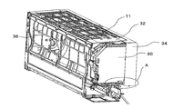
- FIG. 2 is an exploded perspective view of the indoor unit 100 of the air conditioner of FIG.
- the front panel 33 and the side panel 31 are removed, and the housing side surface portion 35 a that is the internal structure on the right side surface of the housing 30 and the internal structure on the left side surface of the housing 30. It is a figure of the state which removed the case side part 35b which is.
- a housing front portion 36 is arranged on the front side from which the front panel 33 is removed.
- An electrical component box 20 in which a control device for controlling the indoor unit 100 is incorporated is disposed on the right side surface of the housing front portion 36.
- casing 30 may comprise a some component integrally.
- the top panel 32 and the housing front part 36 may be integrated into a single component.
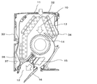
- FIG. 3 is a cross-sectional view of the indoor unit 100 of the air conditioner of FIG.
- FIG. 3 is a view of the cross section of the indoor unit 100 as viewed from the right side of the housing 30.
- the front surface portion 36 is disposed on the front surface side
- the rear casing 34 is disposed on the rear surface surface, so that the main air passage 10 is formed.
- the air outlet 12 is provided in a housing bottom portion 37 located at a lower portion of the housing front portion 36.
- the housing bottom 37 also constitutes the main air passage 10 around the outlet 12.
- a left and right wind direction plate 15 is installed inside the air outlet 12 in order to adjust the left and right wind directions.
- an up and down air direction plate 16 is provided so as to open and close the air outlet 12 in order to adjust the vertical air direction.
- a heat exchanger 13 is arranged on the upstream side of the main air passage 10, that is, on the suction port 11 side.
- a blower 14 is disposed downstream of the heat exchanger 13.
- the heat exchanger 13 corresponds to the heat exchanger of the present invention, and the blower 14 corresponds to the blower of the present invention.
- the heat exchanger 13 is arranged so as to surround the front side from the upper side of the blower 14.
- the blower 14 When the blower 14 generates an air flow by driving a motor (not shown), the air sucked from the suction port 11 passes through the heat exchanger 13 and is sent to the blower port 12.
- the heat exchanger 13 exchanges heat between the refrigerant flowing in the heat exchanger pipe and the indoor air supplied by the blower 14.
- the blower 14 uses a cross flow fan in the first embodiment, but is not limited to this.
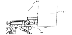
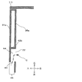
- FIG. 4 is a diagram of the air conditioner indoor unit 100 shown in FIG. 1 with the front panel 33 and the right casing side surface 35a removed.
- FIG. 5 is an enlarged view around the room temperature sensor 50 of FIG.
- An enlarged view of the room temperature sensor peripheral portion A of FIG. 4 corresponds to FIG. 4 and 5, a room temperature sensor 50 for detecting the room temperature is attached to the bottom of the electrical component box 20.
- the room temperature sensor 50 is disposed inside the housing side surface portion 35a. Note that the room temperature sensor 50 is formed of, for example, a thermistor.
- the room temperature sensor 50 By not arranging the room temperature sensor 50 adjacent to the heat exchanger 13, the room temperature sensor 50 is not affected by the heat of the heat exchanger 13. Therefore, the room temperature sensor 50 can detect the correct room temperature.
- the room temperature sensor 50 is disposed at a location near the electrical component box 20 below the electrical component box 20.
- the room temperature detected by the room temperature sensor 50 is used for air conditioning control. Therefore, the room temperature sensor 50 is connected to a control device (not shown) in the electrical component box 20 by wiring. In order to shorten the wiring between the room temperature sensor 50 and the control device, the room temperature sensor 50 is desirably arranged in the vicinity of the electrical component box 20.
- heat is generated in the control device by performing air conditioning control.
- the electrical component box 20 also generates heat during operation of the air conditioner. Since the heat generated in the electrical component box 20 is likely to move upward, the room temperature sensor 50 is desirably disposed below the electrical component box 20. However, the arrangement of the room temperature sensor 50 is not limited to the above arrangement as long as the influence of heat of the electrical component box 20 can be suppressed.
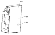
- FIG. 6 is a perspective view of the casing side surface portion 35a of the indoor unit 100 of the air conditioner according to Embodiment 1 of the present invention.
- a ventilation port 22 corresponding to the position of the room temperature sensor 50 disposed inside the housing 30 is formed in the housing side surface portion 35 a.
- the room temperature sensor 50 is located inside the vent hole 22 of the housing side surface portion 35a.
- the room temperature sensor 50 is arranged as close to the indoor space as possible inside the housing 30 in order to detect a more accurate room temperature.
- it is arrange
- the vent 22 is opened toward the side surface of the indoor unit 100 and is covered with the side panel 31a.
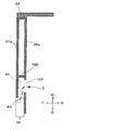
- FIG. 7 is a diagram in which the side panel 31a of the indoor unit 100 of FIG. 1 is removed.
- FIG. 7 is a diagram illustrating the right side of the indoor unit 100 as viewed from the front.
- a vent 22 corresponding to the room temperature sensor 50 is formed in the right side surface 35 a of the indoor unit 100 when viewed from the front.
- a side panel 31 a is attached so as to cover a casing side surface portion 35 a including the vent hole 22.
- the vent 22 is not exposed on the surface of the indoor unit 100 on the right side when viewed from the front of the indoor unit 100 shown in FIG. Since no hole is seen, the vent 22 does not affect the design of the indoor unit 100.
- the vent hole 22 is covered with the side panel 31a and does not affect the design of the indoor unit 100, the opening area can be increased within a range that does not protrude from the side panel 31a.
- FIG. 8 is a perspective view of the right side panel 31a of the indoor unit 100 of FIG. 1 viewed from the back side. That is, FIG. 8 is a perspective view when the side panel 31a is viewed from the inside of the indoor unit 100 to the outside.
- the side panel 31a includes a flat base 40 and outer peripheral walls 41a to 41d rising from the outer edge of the base 40 in the normal direction of the base 40. That is, the side panel 31a is not a mere flat plate, but has a box-like structure in which excess meat is removed.
- outer peripheral wall 41b turns into the front side of indoor unit 100, and outer peripheral wall 41d faces the back side of indoor unit 100.
- the outer peripheral wall 41a is on the top surface side of the indoor unit 100, and the outer peripheral wall 41c is on the bottom surface side.
- a part of the outer peripheral wall 41 d is cut out into a rectangular shape and serves as an air inlet 43.
- a flow path wall 42 a and a flow path wall 42 c extend from the air inlet 43 toward the inner side from the outer edge of the base 40.
- a flow path wall 42b is installed at an end portion where the flow path wall 42a and the flow path wall 42c extend so as to connect the flow path wall 42a and the flow path wall 42c. That is, the flow path walls 42a to 42c are provided in a bag shape with the air inlet 43 as the inlet side.
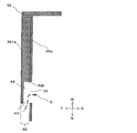
- FIG. 9 is a schematic view of the right side surface of the indoor unit 100 of FIG.
- the side surface of the housing 30 has a first surface 38 located outside the housing 30 and a second surface 39 located away from the first surface 38 toward the inside of the housing. .
- a step surface 45 formed perpendicular to the first surface 38 and the second surface.
- the first surface 38 is a part of the side panel 31a.
- the second surface 39 is configured by the housing side surface portion 35a and the back casing 34.
- the step surface 45 faces the back side of the housing 30.
- the step surface 45 is provided with a concave portion opened toward the back side, and the opening of the concave portion is an air inlet 43.
- a hole is formed in the concave portion toward the inside of the housing 30, and the hole is a vent 22.
- FIG. 10 is a view showing a BB cross section of FIG. 1 in the first embodiment of the present invention.
- FIG. 10 is a diagram illustrating the side panel 31 a, the casing side surface 35 a, and the front panel 33 in the casing 30 of the indoor unit 100 in a cross section including the air inlet 43 and the vent 22.
- the side panel 31a and the casing side surface 35a are assembled in contact with each other as shown in FIG.
- a step 46 is formed by the side panel 31a and the casing side surface 35a.
- the step 46 is formed so that the back side of the indoor unit 100 becomes the step surface 45.
- the air inlet 43 is provided on the step surface 45 and is open.
- the step surface 45 of the step 46 is disposed at a predetermined distance from the back surface of the housing 30 attached to the indoor wall to the front surface side. If the stepped surface 45 is too close to the back surface of the housing 30, when the indoor unit 100 is installed on the indoor wall, the air inlet 43 and the wall surface may be close to each other, and the air suction amount may be reduced. is there.
- the air flow path 44 surrounded by the flow path walls 42a to 42c is provided so as to cover the vent hole 22 provided in the side surface portion 35a of the casing from the side surface side.
- the flow path walls 42 a to 42 c forming the air flow path 44 are installed so as to surround the three directions around the opening of the vent hole 22.
- the flow path walls 42 a to 42 c are open toward the back side of the housing 30.
- the flow path walls 42a to 42c are assembled in contact with the surface of the housing side surface portion 35a where the vent hole 22 is opened.
- the air flowing from the air inlet 43 due to the rotation of the blower 14 is air It collects in the flow path 44 and is introduced into the vent 22. That is, a path is formed between the side panel 31a and the casing side surface portion 35a from the air inlet 43 to the vent 22 via the air flow path 44.
- Air in the room in which the indoor unit 100 of the air conditioner is installed flows into the housing 30 as an air flow C shown in FIG.
- the flow path walls 42a to 42c surround the vent hole 22 in a rectangular shape.
- the flow path walls 42a to 42c may have a U shape and a triangular shape surrounding the vent hole 22 by two walls.
- the direction in which the air inlet 43 is opened and the direction in which the vent 22 is opened are in a perpendicular relationship. That is, since the air vent 22 is opened in the direction perpendicular to the side surface of the indoor unit 100, the air inflow port 43 is opened toward the back side of the indoor unit 100.
- a room temperature sensor 50 is disposed on the back side of the vent 22.
- the vent 22 is not limited to a form that opens in a direction perpendicular to the side surface of the indoor unit 100. It is only necessary that the vent 22 has a flow path wall 42 around it and an air flow path 44 is formed so that air can be introduced into the room temperature sensor 50.
- the air inlet 43 is provided toward the back side of the indoor unit 100. As a result, the air inlet 43 cannot be seen from the front, bottom, and side directions of the indoor unit 100, so the air inlet 43 does not affect the appearance of the indoor unit 100. Thereby, the designability of the indoor unit 100 can be improved.
- the step 46 formed by the side panel 31a and the casing side surface 35a is provided at a predetermined distance from the back of the indoor unit 100 toward the front. And since the air inlet 43 provided in the step 46 is directed to the back side of the indoor unit 100, even if the indoor unit 100 is installed indoors with the right side surface of the indoor unit 100 close to the wall surface, Since the air inlet 43 is not blocked by the wall surface, the air flow to the air inlet 43 can be ensured.
- the air inflow port 43 is opened toward the back surface of the indoor unit 100, and the vent 22 is opened toward the side surface and covered with the side panel 31a. With this structure, the air inlet 43 and the vent 22 are not visible from the side surface side. Therefore, the opening area of the air inlet 43 and the vent 22 can be increased. Therefore, since the air flow rate to the room temperature sensor 50 can be increased freely, the accuracy of room temperature detection of the room temperature sensor 50 can be improved.
- Air flow for room temperature detection> 11 is a diagram in which the positional relationship between the vent 22 and the air inlet 43 is changed with respect to FIG.
- the air flow C through which the air flowing in from the air inlet 43 flows has an L shape.
- the vent 122 is disposed on the far side with a distance from the air inlet 43.
- the edge part of the indoor unit front side of the vent hole 22 is located in the indoor unit back side rather than the flow-path wall 42b arrange
- FIG. On the other hand, in FIG.
- the end of the vent unit 22 on the rear side of the vent unit 22 is disposed at the same position as the opening of the air inlet 43.
- the front side end is disposed at the same position as the wall surface of the flow path wall 42b. That is, the air vent 22 is surrounded by the base 40 of the side panel 31a and the flow path walls 42a to 42c, and the air flow path 44 is formed so that the air flowing from the air inflow port 43 is passed through the side panel. It is possible to flow from the air vent 22 to the room temperature sensor 50 without diffusing between 31a and the casing side surface portion 35a.
- a secondary air passage is formed between the air vent 22 and the main air passage 10, and when the blower 14 of the main air passage 10 is activated, not only the air inlet 11 but also the air in the auxiliary air passage 10 Be drawn into.
- the indoor air also flows into the air inlet 43.
- the room temperature is detected by arranging the room temperature sensor 50 in the air flow. Since the room temperature sensor 50 is disposed near the air inlet 43, the room temperature can be accurately detected without being affected by the temperature inside the indoor unit 100. That is, the air flow introduced into the indoor unit 100 from the air inlet 43 enters the main air passage 10 from the air inlet 43 via the air flow path 44, the vent 22, and the auxiliary air passage.
- the room temperature sensor 50 is arranged upstream, and the electrical component box 20 is arranged downstream thereof.
- the temperature of the air flowing through the auxiliary air passage is detected upstream by the room temperature sensor 50, and after passing therethrough, the air is introduced into the main air passage 10 while cooling the electric component box 20.
- the air flowing through the air flow path 44 exchanges heat with the side panel 31a and the casing side surface portion 35a. Therefore, if the dimension from the air inlet 43 to the vent 22 is long, the temperature of the air changes in the air flow path 44, and the room temperature sensor 50 cannot detect the accurate room temperature. Therefore, it is desirable that the dimension from the air inlet 43 to the room temperature sensor 50 is configured to be short. That is, as shown in FIG. 10, a configuration in which the end of the vent 22 on the rear side of the indoor unit is arranged at the same position as the opening of the air inlet 43 at the position in the front-rear direction of the indoor unit 100 is desirable. It is.
- the indoor unit 100 can detect an accurate room temperature and does not have a hole for detecting the room temperature on the side surface of the indoor unit 100, and thus is not affected by the appearance design.
- Embodiment 1 the configuration in which the room temperature sensor 50 is arranged on the right side surface when viewed from the front of the indoor unit 100 has been described.
- the room temperature sensor 50 is not limited to the right side of the indoor unit 100.
- Embodiment 2 the structure of the side panel 31a is changed from that of the first embodiment.
- the description will focus on changes from the first embodiment. Parts having the same configuration as the indoor unit 100 of the air conditioner according to Embodiment 1 are assigned the same reference numerals, and the description thereof is omitted.
- FIG. 12 is a perspective view of the right side panel 231a of the indoor unit 200 according to the second embodiment of the present invention as viewed from the back side.
- the indoor unit 200 is different from the indoor unit 100 of the first embodiment in the structure of the side panel 31a and the casing side surface part 35a.
- the side panel 231 a according to the second embodiment includes outer peripheral walls 41 b and 41 c that rise from the outer edge of the base 40 in the normal direction of the base 40. That is, in the first embodiment, the side panel 231a has a structure without the outer peripheral wall 41a on the top surface side and the outer peripheral wall 41d on the back surface side.
- the side panel 231a does not include the outer peripheral wall 41a on the top surface side and the outer peripheral wall 41d on the rear surface side, but has a structure in which the outer peripheral wall 41 is not provided in a portion that is difficult for the user of the indoor unit 200 to visually recognize. It does not affect the appearance design of 200. Since the indoor unit 200 including the side panel 231a having such a structure does not have the outer peripheral wall 41, the amount of resin for molding the side panel 231a can be reduced, and the cost can be reduced.
- the side panel 231a includes flow path walls 42a to 42c.
- the air flow path 44 surrounded by the flow path walls 42a to 42c and the base portion 40 is provided so as to cover the vent hole 22 provided in the housing side surface portion 35a from the side surface side.
- the flow path walls 42 a to 42 c forming the air flow path 44 are installed so as to surround the three directions around the opening of the vent hole 22.
- the side panel 231a does not have an outer peripheral wall 41d on the back side, and the flow path wall 42a and the flow path wall 42c extend from the outer edge of the base 40 toward the inside.
- An air inflow port 43 is formed by the end surface of the flow path wall 42 a and the flow path wall 42 c located on the outer edge side of the base portion 40 and the end surface of the base portion 40.
- FIG. 13 is a perspective view of the housing side surface portion 235a on the right side of the indoor unit 200 according to Embodiment 2 of the present invention.
- the casing side surface portion 235a may be provided with a hole 25 on a surface covered with the side panel 231a.
- the hole 25 is provided on a surface other than the surface constituting the air flow path 44 in contact with the flow path walls 42 a to 42 c provided on the side panel 231 a around the vent hole 22.
- the air flow C (see FIGS. 10 and 11) that introduces indoor air to the room temperature sensor 50 in the portion from the air inlet 43 to the vent 22 is the same as in the first embodiment. It is formed.
- the openings on the top side and the back side where the outer peripheral wall 41 of the side panel 231 a is not provided are openings for introducing air into the holes 25.
- a space between the base 40 and the housing side surface portion 235a is formed, and the space serves as a path for introducing air into the hole 25.
- the side panel 231a and the housing side surface portion 235a on the right side of the indoor unit 200 have been described above, on the left side of the indoor unit 200, the side panel 31b is mounted on the top side and the back side in the same manner as the side panel 231a.
- a structure in which the outer peripheral wall 41 is not provided may be provided, and the hole 25 may be provided in the housing side surface portion 35b similarly to the housing side surface portion 235a.
- Embodiment 3 FIG.
- the structure of the side panel 31a is changed from that of the first embodiment.
- the description will focus on the changes made to the first embodiment.
- Parts having the same configuration as the indoor unit 100 of the air conditioner according to Embodiment 1 are assigned the same reference numerals, and the description thereof is omitted.
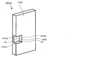
- FIG. 14 is a perspective view of the right side panel 331a of the indoor unit 300 according to Embodiment 3 of the present invention as seen from the back side.
- the indoor unit 300 is obtained by changing the side panel 31a with respect to the indoor unit 100 of the first embodiment, and the other structures are the same.
- the side panel 331a does not have to have a hollow structure and the flow path walls 42a to 42c as in the side panel 31a of the first embodiment.
- a concave portion 348 is provided in a part of the plate portion 340, and vertical walls formed by providing the concave portion 348 can be flow path walls 342a to 342c.
- the flow path wall 342 does not necessarily have to be perpendicular to the surface of the flat plate portion of the plate portion 340, that is, the external side surface of the indoor unit 300, and may be inclined.
- FIG. 15 is a view showing a cross section BB of FIG. 1 of the indoor unit according to Embodiment 3 of the present invention.
- the concave shape portion 348 covers the vent hole 22 provided in the housing side surface portion 35 a from the side surface side of the indoor unit 300, and forms the air flow path 44.
- An opening facing the back side of the indoor unit 300 of the concave shaped portion 348 serves as an air inlet 43.
- the indoor unit 100 of the first embodiment is further improved.
- the structure of the side panel 31a can be changed.
- Embodiment 4 FIG.
- the structure of the casing side surface portion 35a is changed from that of the first embodiment.
- the description will focus on the changes made to the first embodiment.
- Parts having the same configuration as the indoor unit 100 of the air conditioner according to Embodiment 1 are assigned the same reference numerals, and the description thereof is omitted.
- FIG. 16 is a perspective view of the right housing side surface portion 435a of the indoor unit 400 according to Embodiment 4 of the present invention.
- FIG. 16 schematically shows the surface of the housing side surface portion 35a shown in FIG. 6 around the surface on which the vent hole 22 is provided.
- the indoor unit 400 is obtained by changing the side panel 31a and the casing side surface 35a with respect to the indoor unit 100 of the first embodiment, and the other structures are the same.
- a step is provided on the housing side surface portion 435a.
- the step surface 439 is formed facing the back side of the indoor unit 400.
- the housing side surface portion 435a has a surface 437 provided with the vent hole 22 and a surface 437 that is separated from the surface 438 by a predetermined distance in the side surface direction of the indoor unit 400, for example, 5 mm in the fourth embodiment. That is, a step of 5 mm is generated between the surface 438 and the surface 437.
- the surface 437 is recessed only in the periphery of the vent 22, and walls are provided around the vent 22 perpendicular to the surface 438 to form flow path walls 442 a to 442 c.
- the flow path wall 442 does not necessarily have to be perpendicular to the surface 438 on which the vent hole 22 is provided, and may be inclined.
- FIG. 17 is a diagram showing a BB cross section of FIG. 1 according to the fourth embodiment of the present invention.
- a side panel 431a is assembled to the surface 437 shown in FIG.
- the side panel 431a has a flat plate shape and covers the channel wall 442 around the vent hole 22 provided in the casing side surface 435a to form the air channel 44.
- An opening portion of the flow path wall 442 around the vent 22 facing the back side of the indoor unit 400 serves as an air inflow port 43.
- the path for introducing indoor air into the room temperature sensor 50 has the same configuration as in the first embodiment. Therefore, also in Embodiment 4, indoor air flows into the housing 30 in the same manner as the airflow C shown in FIG.
- the indoor unit 100 of the first embodiment is further improved.
- the structure of the case side surface portion 35a can be changed. Note that in the housing side surface portion 435a, the surface 437 shown in FIG. 16 may be formed in a box shape by hollowing out meat. If the flow path walls 442a to 442c around the vent hole 22 are provided even in the box shape, the air flow path 44 and the air inflow port 43 are formed by being covered with the side panel 431a.
- the opening of the air inlet 43 is not limited to being formed on the back side, but may be formed on the top side, the bottom side, or the front side.
- the direction of the air flow path 44 and the flow path walls 42, 242, 342, and 442 constituting the air flow path 44 may be changed according to the surface on which the air inlet 43 is formed.
- the configuration described in the first to fourth embodiments of the present invention in which the air inlet 43 is provided on the back side of the indoor unit is convenient for efficiently taking in the indoor air into the indoor unit.
- the air flow path is formed in the same manner as in the first to fourth embodiments, so that the temperature of the indoor air can be detected.
- the indoor units 100, 200, 300, and 400 of the air conditioner according to Embodiments 1 to 4 of the present invention include a housing 30 whose back surface is attached to a wall, and a suction port 11 and an air outlet provided in the housing 30. 12, a heat exchanger 13 and a blower 14 disposed in the main air passage 10 from the suction port 11 to the blower outlet 12, and a room temperature sensor 50 that detects the temperature of the taken-in air,
- the air inlet 43 for taking in the air sent to the room temperature sensor 50 is provided on the side surface adjacent to the rear surface.
- the room temperature sensor 50 is provided in an air passage connecting the air inlet 43 to the main air passage 10, and the air inlet 43 is opened toward the back side.
- the indoor units 100, 200, 300, and 400 of the air conditioner are configured so that the indoor air to be sent to the room temperature sensor 50 can be transmitted from the air inlet 43 at a position that is difficult for the user to visually recognize. Can be captured. Since the air inlet 43 is provided at a position where it is difficult for the user to visually recognize the air inlet 43, the opening area of the air inlet 43 can be freely set. Therefore, the indoor units 100, 200, 300, and 400 can accurately detect the room temperature and can be provided with the air inlet 43 so as not to affect the appearance design.
- the side surface of the housing 30 includes a first surface 38 that is located outside the housing 30, and a first surface 38 has a step surface 45 formed between the second surface 39 and the second surface 39 located away from the inner side of the housing 30.
- the step surface 45 faces the back surface side of the housing 30 and is on the back surface of the step surface 45.
- the air inflow port 43 is an opening part of a concave-shaped part provided with the concave-shaped part opened toward the side.
- Air conditioner indoor units 100, 200, 300, and 400 according to Embodiments 1 to 4 of the present invention include a vent 22 that communicates with the inside of the housing 30 inside the concave portion, and an air inlet 43 To the room temperature sensor 50 through the recessed portion and the vent hole 22.
- the indoor units 100, 200, 300, and 400 can prevent the air guided to the room temperature sensor from being affected by the heat inside the housing 30 in addition to the above effects. it can.
- the casing 30 of the indoor units 100, 200, 300, and 400 of the air conditioner according to Embodiments 1 to 4 of the present invention covers the casing side surface portion 35a having the side structure and the casing side surface portion 35a.
- a side surface panel 31a, the housing side surface portion 35a has a second surface 39 and a vent 22, and the side surface panel 31 has a first surface 38 and is assembled to the housing side surface portion 35a.
- the step surface 45 is formed.
- the concave portion includes a flow path wall 42 standing around the vent 22, the flow path wall 42 is opened on the back side of the housing 30, and the side panel 31 a covers the first surface 38.
- a base 40 on the outside of the body 30, and an outer peripheral wall 41 standing from the outer edge of the base 40.
- the air flow path 44 includes a vent hole 22, a surface provided with the vent hole 22, and a flow path.
- a wall 42 and a base 40 are formed. Furthermore, the flow path wall 42 is erected on the casing side surface portion 35a, or is erected on the base portion of the side panel 31a.
- the indoor units 100, 200, 300, and 400 have the side panel 31 or the casing side surface 35a, which is a component constituting the casing 30, having a hollow structure. , Can be manufactured at low material costs.
- the room temperature sensors 50 of the indoor units 100, 200, 300, and 400 of the air conditioners according to Embodiments 1 to 4 of the present invention are installed in the auxiliary air passage that connects the vent 22 and the main air passage 10.
- the electric component box 20 which accommodates the control board which controls an indoor unit is further provided, the electric component box 20 is installed in a subair path, and the room temperature sensor 50 is installed in the lower part of the electric component box 20.
- the indoor units 100, 200, 300, and 400 are configured so that the indoor air is guided to the room temperature sensor 50 along with the operation of the air conditioner and the room temperature is detected while the room temperature is detected. It becomes possible to cool the internal structure of the component box 20 or the like. Thereby, the temperature detection by the room temperature sensor 50 is possible, suppressing the temperature influence of the electrical component box 20.
Abstract
Description
<空気調和機の室内機100>
図1は、本発明の実施の形態1における空気調和機の室内機100の外観斜視図である。図1に示されるように、室内機100は、直方体の筐体30の上面に吸込口11が配置され、下面に吹出口12が配置されている。筐体30の正面は、前面パネル33で覆われている。また、筐体30の側面は、正面から向かって右側の側面を側面パネル31a、正面から向かって左側の側面を側面パネル31bで覆っている。筐体30の上面は、上面パネル32で覆われており、上面パネル32に開口が設けられており吸込口11となっている。筐体30の背面側は、背面ケーシング34があり、背面ケーシング34を室内の壁面に固定して室内機100が設置される。 Embodiment 1.
<Air conditioner
FIG. 1 is an external perspective view of an air conditioner
図2は、図1の空気調和機の室内機100の分解斜視図である。筐体30を構成する部品のうち、前面パネル33、側面パネル31、を外し、さらに筐体30の右側の側面の内部構造である筐体側面部35a及び筐体30の左側の側面の内部構造である筐体側面部35bを外した状態の図である。前面パネル33を外した正面側は、筐体正面部36が配置されている。筐体正面部36の右側の側面には、内部に室内機100を制御する制御装置が内蔵された電気部品箱20が配置されている。なお、筐体30を構成する各部品は、複数の部品を一体に構成してもよい。例えば、上面パネル32と筐体正面部36とを一体にして1つの部品として構成してもよい。 <Structure of
FIG. 2 is an exploded perspective view of the
図3は、図1の空気調和機の室内機100の断面図である。図3は、室内機100の断面を筐体30の右側から見た図である。図3に示されるように、筐体30の上面にある吸込口11から吹出口12の間は、前面側が筐体正面部36、背面側が背面ケーシング34が配置され、主風路10が形成されている。また、吹出口12は、筐体正面部36の下部に位置する筐体底部37に設けられている。筐体底部37も吹出口12の周辺の主風路10を構成している。吹出口12の内部には、左右の風向を調整するために左右風向板15が、設置されている。吹出口12の開口部には、上下の風向を調整するために上下風向板16が吹出口12を開閉できる様に設けられている。主風路10の上流側、つまり吸込口11側には、熱交換器13が配置されている。熱交換器13の下流には送風機14が配置されている。なお、熱交換器13は、本願発明の熱交換器に相当し、送風機14は、本願発明の送風機に相当する。熱交換器13は、送風機14の上側から前面側を囲む様に配置されている。送風機14が図略のモータの駆動によって空気の流れを生じさせると、吸込口11から吸入された空気は、熱交換器13を通過し、吹出口12へと送られる。熱交換器13は、熱交換器配管内を流れる冷媒と送風機14によって供給される室内空気との間で熱交換させる。送風機14は、実施の形態1においてはクロスフローファンが用いられているが、これに限定されるものでは無い。 <Internal structure of
FIG. 3 is a cross-sectional view of the
図4は、図1に示す空気調和機の室内機100の前面パネル33と右側の筐体側面部35aを取り外した状態の図である。図5は、図4の室温センサ50周辺の拡大図である。図4の室温センサ周辺部Aの拡大図が図5に相当する。図4及び図5において電気部品箱20の底部に、室内温度を検出するための室温センサ50が取り付けられている。この室温センサ50は筐体側面部35aの内側に配置されている。なお、室温センサ50は、例えばサーミスタにより構成される。 <Structure on the side of
FIG. 4 is a diagram of the air conditioner
図7は、図1の室内機100の側面パネル31aを取り外した図である。図7は、室内機100の正面から見ての右側を示した図である。図6及び図7に示されるように、室内機100の正面から見て右側の筐体側面部35aに室温センサ50に対応する通気口22が形成されている。 <Structure of
FIG. 7 is a diagram in which the
図9は、図1の室内機100の右側側面を背面上方から見た模式図である。筐体30の側面は、図9に示される様に、筐体30の外側に位置する第1面38と、第1面38から筐体の内側方向に離れて位置する第2面39を有する。第1面38と第2面39との間には、第1面38及び第2面に対し垂直に形成された段差面45を有する。第1面38は、側面パネル31aの一部である。第2面39は、実施の形態1においては筐体側面部35a及び背面ケーシング34により構成される。段差面45は、筐体30の背面側に向いている。段差面45には、背面側に向いて開口された凹形状部を備え、その凹形状部の開口部が空気流入口43になっている。凹形状部の内部には、筐体30の内側に向かって穴が開けられており、その穴が通気口22である。 <Air flow path for temperature detection>
FIG. 9 is a schematic view of the right side surface of the
図11は、図10に対し通気口22と空気流入口43の位置関係を変更した図である。図10及び図11に示される様に、空気流入口43から流入する空気の流れる空気流CはL字状になっている。図11においては、通気口122は、空気流入口43から距離をおいて奥側に配置されている。そして、空気流路44の室内機正面側に配置されている流路壁42bよりも室内機背面側に、通気口22の室内機正面側の端部が位置している。一方、図10においては、室内機100の前後方向の位置において、空気流入口43の開口と同じ位置に通気口22の室内機背面側の端部が配置されており、通気口22の室内機正面側の端部は、流路壁42bの壁面と同じ位置に配置されている。つまり、通気口22は、側面パネル31aの基部40と流路壁42a~42cとにより囲まれており、空気流路44が形成されることにより、空気流入口43から流れてきた空気を側面パネル31aと筐体側面部35aとの間で拡散させることなく、通気口22から室温センサ50へ流すことができる。 <Air flow for room temperature detection>
11 is a diagram in which the positional relationship between the
実施の形態2は、実施の形態1に対し側面パネル31aの構造を変更したものである。なお、実施の形態2においては、実施の形態1に対する変更点を中心に説明する。実施の形態1の空気調和機の室内機100と同一の構成を有する部位には同一の符号を付してその説明を省略する。 Embodiment 2. FIG.
In the second embodiment, the structure of the
実施の形態3は、実施の形態1に対し側面パネル31aの構造を変更したものである。なお、実施の形態3においては、実施の形態1に対する変更点を中心に説明する。実施の形態1の空気調和機の室内機100と同一の構成を有する部位には同一の符号を付してその説明を省略する。
In the third embodiment, the structure of the
実施の形態4は、実施の形態1に対し筐体側面部35aの構造を変更したものである。なお、実施の形態4においては、実施の形態1に対する変更点を中心に説明する。実施の形態1の空気調和機の室内機100と同一の構成を有する部位には同一の符号を付してその説明を省略する。 Embodiment 4 FIG.
In the fourth embodiment, the structure of the casing
本発明の実施の形態1~4に係る空気調和機の室内機100、200、300、400は、背面が壁に取り付けられる筐体30と、筐体30に設けられた吸込口11及び吹出口12と、吸込口11から吹出口12に至る主風路10に配置された熱交換器13及び送風機14と、取り込まれた空気の温度を検知する室温センサ50と、を備え、筐体30は、背面に隣接した側面に、室温センサ50に送る空気を取り込む空気流入口43を有する。室温センサ50は、空気流入口43から主風路10までを接続する風路に設けられ、空気流入口43は、背面側に向いて開口されている。
このように構成されることにより、空気調和機の室内機100、200、300、400は、室温センサ50に送り込むための室内の空気を、使用者から視認しにくい位置にある空気流入口43から取り込むことができる。使用者から視認しにくい位置に空気流入口43が設けられているため、空気流入口43はその開口面積を自由に設定することができる。そのため、室内機100、200、300、400は、正確に室温を検知することができ、かつ外観デザインに影響しないように空気流入口43を設けることができる。 <Effect of the present invention>
The
With this configuration, the
このように構成されることにより、室内機100、200、300、400は、上記の効果に加えて、筐体30にスペースの効率よく空気流入口43を設けることができる。 In the
With this configuration, the
このように構成されることにより、室内機100、200、300、400は、上記の効果に加えて、室温センサに導かれる空気を筐体30の内部の熱影響を受けることを防止することができる。 Air conditioner
With this configuration, the
このように構成されることにより、室内機100、200、300、400は、上記の効果に加えて、筐体30を構成する部品である側面パネル31又は筐体側面部35aを中空構造にして、材料費を抑えて製作することができる。 The
With this configuration, in addition to the above effects, the
このように構成されることにより、室内機100、200、300、400は、空気調和機の運転とともに室温センサ50に室内の空気が導かれ室温検知しつつ、室温を測定した後の空気は電気部品箱20等の内部構造を冷却することが可能となる。これにより、電気部品箱20の温度影響も抑えつつ、室温センサ50による温度検知が可能となっている。 The
With this configuration, the
Claims (9)
- 背面が壁に取り付けられ吸込口及び吹出口が形成された筐体と、
前記吸込口から前記吹出口に至る主風路に配置された熱交換器及び送風機と、
取り込んだ空気の温度を検知する室温センサと、を備え、
前記筐体は、
前記背面に隣接した側面に、前記室温センサに送る空気を取り込む空気流入口を有し、
前記室温センサは、
前記空気流入口から前記主風路までを接続する風路に設けられ、
前記空気流入口は、
背面側に向いて開口されている、空気調和機の室内機。 A case where the back is attached to the wall and a suction port and a blowout port are formed;
A heat exchanger and a blower arranged in a main air passage from the suction port to the blowout port;
A room temperature sensor that detects the temperature of the air taken in, and
The housing is
An air inlet that takes in air to be sent to the room temperature sensor on a side surface adjacent to the back surface;
The room temperature sensor is
Provided in the air passage connecting the air inlet to the main air passage;
The air inlet is
An indoor unit of an air conditioner that opens toward the back side. - 前記筐体の前記側面は、
前記筐体の外側に位置する第1面と、該第1面から前記筐体の内側方向に離れて位置する第2面との間に形成された段差面を有し、
前記段差面は、
前記筐体の背面側に向き、
当該段差面に背面側に向いて開口された凹形状部を備え、
前記凹形状部の開口は、
前記空気流入口である、請求項1に記載の空気調和機の室内機。 The side surface of the housing is
A step surface formed between a first surface located outside the housing and a second surface located away from the first surface in the inner direction of the housing;
The step surface is
Facing the back side of the housing,
The stepped surface has a concave portion that opens toward the back side,
The opening of the concave portion is
The indoor unit of an air conditioner according to claim 1, which is the air inlet. - 前記凹形状部の内部に前記筐体の内部に連通する通気口を備え、
前記空気流入口から前記凹形状部、前記通気口を経て前記室温センサに至る空気流路を有する、請求項2に記載の空気調和機の室内機。 Provided with a vent hole communicating with the inside of the housing inside the concave portion,
The indoor unit of the air conditioner according to claim 2, further comprising an air flow path from the air inlet to the room temperature sensor through the concave portion and the vent. - 前記筐体は、
側面側の構造となる筐体側面部と、
該筐体側面部を覆う側面パネルと、を備え、
前記筐体側面部は、
前記第2面と
前記通気口と、を有し、
前記側面パネルは、
前記第1面を有し、
前記筐体側面部に組み付けられて前記段差面を形成する、請求項3に記載された空気調和機の室内機。 The housing is
A side surface of the housing that is the structure of the side surface;
A side panel covering the side surface of the housing,
The housing side surface portion is
The second surface and the vent,
The side panel is
Having the first surface;
The indoor unit of an air conditioner according to claim 3, wherein the stepped surface is formed by being assembled to the side surface of the casing. - 前記凹形状部は、
前記通気口の周囲に立設される流路壁を備え、
前記流路壁は、
前記筐体の背面側が開放され、
前記側面パネルは、
前記第1面を前記筐体の外側に有する基部と、
該基部の外縁部から立設する外周壁と、を備え、
前記空気流路は、
前記通気口と、前記通気口が設けられた面と、前記流路壁と、前記基部と、により形成される、請求項4に記載の空気調和機の室内機。 The concave portion is
Comprising a flow path wall standing around the vent,
The channel wall is
The back side of the housing is opened,
The side panel is
A base having the first surface outside the housing;
An outer peripheral wall standing from the outer edge of the base, and
The air flow path is
The indoor unit of the air conditioner according to claim 4, wherein the indoor unit is formed by the vent, the surface on which the vent is provided, the flow path wall, and the base. - 前記流路壁は、
前記筐体側面部に立設される、請求項5に記載の空気調和機の室内機。 The channel wall is
The indoor unit of an air conditioner according to claim 5, wherein the indoor unit is erected on the side surface of the casing. - 前記流路壁は、
前記側面パネルの前記基部に立設される、請求項5に記載の空気調和機の室内機。 The channel wall is
The indoor unit of the air conditioner according to claim 5, wherein the indoor unit is erected on the base of the side panel. - 前記室温センサは、
前記通気口と前記主風路とを接続する副風路に設置される、請求項3~7の何れか1項に記載の空気調和機の室内機。 The room temperature sensor is
The indoor unit of an air conditioner according to any one of claims 3 to 7, wherein the indoor unit is installed in a sub air passage connecting the vent hole and the main air passage. - 室内機を制御する制御基板を収納する電気部品箱をさらに備え、
前記電気部品箱は、
前記副風路に設置され、
前記室温センサは、
前記電気部品箱の下部に設置される、請求項8に記載の空気調和機の室内機。 It further includes an electrical component box that houses a control board that controls the indoor unit.
The electrical component box is
Installed in the secondary airway,
The room temperature sensor is
The indoor unit of the air conditioner according to claim 8, which is installed at a lower part of the electric component box.
Priority Applications (7)
| Application Number | Priority Date | Filing Date | Title |
|---|---|---|---|
| AU2016392646A AU2016392646B2 (en) | 2016-02-08 | 2016-02-08 | Indoor unit for air-conditioning apparatus |
| CN201680004008.2A CN107278254B (en) | 2016-02-08 | 2016-02-08 | The indoor unit of air conditioner |
| US15/781,574 US10663180B2 (en) | 2016-02-08 | 2016-02-08 | Indoor unit for air-conditioning apparatus |
| RU2018131348A RU2690641C1 (en) | 2016-02-08 | 2016-02-08 | Indoor unit for air conditioning installation |
| PCT/JP2016/053636 WO2017138063A1 (en) | 2016-02-08 | 2016-02-08 | Air conditioner indoor unit |
| EP16863210.7A EP3236170B1 (en) | 2016-02-08 | 2016-02-08 | Air conditioner indoor unit |
| JP2017566249A JP6541806B2 (en) | 2016-02-08 | 2016-02-08 | Indoor unit of air conditioner |
Applications Claiming Priority (1)
| Application Number | Priority Date | Filing Date | Title |
|---|---|---|---|
| PCT/JP2016/053636 WO2017138063A1 (en) | 2016-02-08 | 2016-02-08 | Air conditioner indoor unit |
Publications (1)
| Publication Number | Publication Date |
|---|---|
| WO2017138063A1 true WO2017138063A1 (en) | 2017-08-17 |
Family
ID=59563048
Family Applications (1)
| Application Number | Title | Priority Date | Filing Date |
|---|---|---|---|
| PCT/JP2016/053636 WO2017138063A1 (en) | 2016-02-08 | 2016-02-08 | Air conditioner indoor unit |
Country Status (7)
| Country | Link |
|---|---|
| US (1) | US10663180B2 (en) |
| EP (1) | EP3236170B1 (en) |
| JP (1) | JP6541806B2 (en) |
| CN (1) | CN107278254B (en) |
| AU (1) | AU2016392646B2 (en) |
| RU (1) | RU2690641C1 (en) |
| WO (1) | WO2017138063A1 (en) |
Families Citing this family (7)
| Publication number | Priority date | Publication date | Assignee | Title |
|---|---|---|---|---|
| CN107923651B (en) * | 2015-08-24 | 2020-10-09 | 三菱电机株式会社 | Indoor unit of air conditioner |
| CN107830581A (en) * | 2017-11-30 | 2018-03-23 | 广东美的制冷设备有限公司 | Wall-hanging air conditioner indoor unit and there is its air conditioner |
| CN107741057A (en) * | 2017-11-30 | 2018-02-27 | 广东美的制冷设备有限公司 | Wall-hanging air conditioner indoor unit and there is its air conditioner |
| CN109864679B (en) * | 2017-12-01 | 2020-10-30 | 青岛海尔股份有限公司 | Refrigerator, air conditioner and dish washing machine integrated machine |
| CN109238370A (en) * | 2018-10-16 | 2019-01-18 | 珠海格力电器股份有限公司 | Detection device and dehumidification device with it |
| JP7022287B2 (en) * | 2019-12-23 | 2022-02-18 | ダイキン工業株式会社 | Air conditioner with antistatic structure |
| US11846453B2 (en) | 2021-01-26 | 2023-12-19 | Rheem Manufacturing Company | Evaporator assemblies and heat pump systems including the same |
Citations (2)
| Publication number | Priority date | Publication date | Assignee | Title |
|---|---|---|---|---|
| JPH11230601A (en) | 1998-02-16 | 1999-08-27 | Toshiba Corp | Air conditioner |
| JP2012112599A (en) * | 2010-11-26 | 2012-06-14 | Hitachi Appliances Inc | Indoor unit of air conditioner |
Family Cites Families (12)
| Publication number | Priority date | Publication date | Assignee | Title |
|---|---|---|---|---|
| JPH0599490A (en) * | 1991-10-04 | 1993-04-20 | Mitsubishi Electric Corp | Cooling/heating machine |
| US5987911A (en) * | 1997-11-13 | 1999-11-23 | Mitsubishi Denki Kabushiki Kaisha | Air conditioner |
| JP4560868B2 (en) * | 1999-12-20 | 2010-10-13 | 株式会社富士通ゼネラル | Air conditioner |
| CN1900605A (en) * | 2005-07-20 | 2007-01-24 | 湖南迅达集团有限公司 | Fume exhaust fan of fume focusing cover with air inlet concave chamber |
| WO2007081083A1 (en) * | 2006-01-16 | 2007-07-19 | Lg Electronics, Inc. | Indoor unit for air conditioner |
| JP2008116103A (en) * | 2006-11-02 | 2008-05-22 | Mitsubishi Electric Corp | Air conditioner |
| JP2008145062A (en) * | 2006-12-11 | 2008-06-26 | Daikin Ind Ltd | Indoor unit of air conditioner |
| JP2010078255A (en) * | 2008-09-26 | 2010-04-08 | Mitsubishi Heavy Ind Ltd | Air conditioner |
| EP2299191A3 (en) * | 2009-09-10 | 2012-05-02 | LG Electronics Inc. | Indoor unit of air conditioner |
| JP5510669B2 (en) * | 2010-10-12 | 2014-06-04 | 株式会社富士通ゼネラル | Air conditioner indoor unit |
| CN103486658B (en) * | 2012-06-12 | 2016-06-08 | 珠海格力电器股份有限公司 | Machine and comprise the conditioner of machine in this air conditioner chamber in air conditioner chamber |
| JP5790621B2 (en) * | 2012-10-31 | 2015-10-07 | ダイキン工業株式会社 | Air conditioning indoor unit |
-
2016
- 2016-02-08 WO PCT/JP2016/053636 patent/WO2017138063A1/en active Application Filing
- 2016-02-08 EP EP16863210.7A patent/EP3236170B1/en active Active
- 2016-02-08 RU RU2018131348A patent/RU2690641C1/en active
- 2016-02-08 CN CN201680004008.2A patent/CN107278254B/en active Active
- 2016-02-08 US US15/781,574 patent/US10663180B2/en active Active
- 2016-02-08 JP JP2017566249A patent/JP6541806B2/en active Active
- 2016-02-08 AU AU2016392646A patent/AU2016392646B2/en active Active
Patent Citations (2)
| Publication number | Priority date | Publication date | Assignee | Title |
|---|---|---|---|---|
| JPH11230601A (en) | 1998-02-16 | 1999-08-27 | Toshiba Corp | Air conditioner |
| JP2012112599A (en) * | 2010-11-26 | 2012-06-14 | Hitachi Appliances Inc | Indoor unit of air conditioner |
Non-Patent Citations (1)
| Title |
|---|
| See also references of EP3236170A4 |
Also Published As
| Publication number | Publication date |
|---|---|
| AU2016392646A1 (en) | 2018-08-02 |
| CN107278254A (en) | 2017-10-20 |
| JP6541806B2 (en) | 2019-07-10 |
| US10663180B2 (en) | 2020-05-26 |
| AU2016392646B2 (en) | 2019-05-02 |
| RU2690641C1 (en) | 2019-06-04 |
| CN107278254B (en) | 2019-11-19 |
| US20190113243A1 (en) | 2019-04-18 |
| EP3236170A4 (en) | 2018-01-10 |
| EP3236170A1 (en) | 2017-10-25 |
| EP3236170B1 (en) | 2018-11-07 |
| JPWO2017138063A1 (en) | 2018-08-30 |
Similar Documents
| Publication | Publication Date | Title |
|---|---|---|
| WO2017138063A1 (en) | Air conditioner indoor unit | |
| JP5218689B2 (en) | Refrigeration unit outdoor unit | |
| JPWO2016139729A1 (en) | Air conditioner indoor unit | |
| JP2009520175A (en) | Fan intake sensor | |
| JP6475040B2 (en) | Air conditioner outdoor unit | |
| JP5994101B2 (en) | Heat exchange ventilator | |
| JP5790621B2 (en) | Air conditioning indoor unit | |
| JP2019203629A (en) | Ceiling embedded type air conditioner | |
| JP5549817B2 (en) | Duct type air conditioner indoor unit | |
| JP6954814B2 (en) | Dehumidifier | |
| JPH11118200A (en) | Outdoor unit of air conditioner | |
| JP5668739B2 (en) | Air conditioning indoor unit | |
| CN210463496U (en) | Indoor unit of air conditioner | |
| JP5557110B2 (en) | Duct type air conditioner indoor unit | |
| JP3894174B2 (en) | Air conditioner electrical component box and air conditioner | |
| JP5495977B2 (en) | Air conditioning ventilator | |
| JP2018119783A (en) | Indoor machine of air conditioner | |
| JP2001132981A (en) | Ceiling embedded air conditioner | |
| JP2010210131A (en) | Air conditioner | |
| JP5096505B2 (en) | Duct unit and environmental test apparatus having the same | |
| JP4882450B2 (en) | Air conditioner | |
| JP6755404B2 (en) | Indoor unit of air conditioner | |
| JP6257335B2 (en) | Air conditioner indoor unit | |
| WO2018189894A1 (en) | Indoor unit for air conditioner | |
| JP2021051005A (en) | Sensor device |
Legal Events
| Date | Code | Title | Description |
|---|---|---|---|
| REEP | Request for entry into the european phase |
Ref document number: 2016863210 Country of ref document: EP |
|
| 121 | Ep: the epo has been informed by wipo that ep was designated in this application |
Ref document number: 16863210 Country of ref document: EP Kind code of ref document: A1 |
|
| ENP | Entry into the national phase |
Ref document number: 2017566249 Country of ref document: JP Kind code of ref document: A |
|
| ENP | Entry into the national phase |
Ref document number: 2016392646 Country of ref document: AU Date of ref document: 20160208 Kind code of ref document: A |
|
| NENP | Non-entry into the national phase |
Ref country code: DE |