WO2017135319A1 - Reactor - Google Patents
Reactor Download PDFInfo
- Publication number
- WO2017135319A1 WO2017135319A1 PCT/JP2017/003651 JP2017003651W WO2017135319A1 WO 2017135319 A1 WO2017135319 A1 WO 2017135319A1 JP 2017003651 W JP2017003651 W JP 2017003651W WO 2017135319 A1 WO2017135319 A1 WO 2017135319A1
- Authority
- WO
- WIPO (PCT)
- Prior art keywords
- resin
- winding
- core
- gap
- coil
- Prior art date
Links
Images

Classifications
-
- H—ELECTRICITY
- H01—ELECTRIC ELEMENTS
- H01F—MAGNETS; INDUCTANCES; TRANSFORMERS; SELECTION OF MATERIALS FOR THEIR MAGNETIC PROPERTIES
- H01F27/00—Details of transformers or inductances, in general
- H01F27/02—Casings
- H01F27/022—Encapsulation
-
- H—ELECTRICITY
- H01—ELECTRIC ELEMENTS
- H01F—MAGNETS; INDUCTANCES; TRANSFORMERS; SELECTION OF MATERIALS FOR THEIR MAGNETIC PROPERTIES
- H01F27/00—Details of transformers or inductances, in general
- H01F27/24—Magnetic cores
- H01F27/255—Magnetic cores made from particles
-
- H—ELECTRICITY
- H01—ELECTRIC ELEMENTS
- H01F—MAGNETS; INDUCTANCES; TRANSFORMERS; SELECTION OF MATERIALS FOR THEIR MAGNETIC PROPERTIES
- H01F27/00—Details of transformers or inductances, in general
- H01F27/28—Coils; Windings; Conductive connections
- H01F27/2823—Wires
-
- H—ELECTRICITY
- H01—ELECTRIC ELEMENTS
- H01F—MAGNETS; INDUCTANCES; TRANSFORMERS; SELECTION OF MATERIALS FOR THEIR MAGNETIC PROPERTIES
- H01F27/00—Details of transformers or inductances, in general
- H01F27/28—Coils; Windings; Conductive connections
- H01F27/30—Fastening or clamping coils, windings, or parts thereof together; Fastening or mounting coils or windings on core, casing, or other support
- H01F27/306—Fastening or mounting coils or windings on core, casing or other support
-
- H—ELECTRICITY
- H01—ELECTRIC ELEMENTS
- H01F—MAGNETS; INDUCTANCES; TRANSFORMERS; SELECTION OF MATERIALS FOR THEIR MAGNETIC PROPERTIES
- H01F27/00—Details of transformers or inductances, in general
- H01F27/28—Coils; Windings; Conductive connections
- H01F27/32—Insulating of coils, windings, or parts thereof
- H01F27/323—Insulation between winding turns, between winding layers
-
- H—ELECTRICITY
- H01—ELECTRIC ELEMENTS
- H01F—MAGNETS; INDUCTANCES; TRANSFORMERS; SELECTION OF MATERIALS FOR THEIR MAGNETIC PROPERTIES
- H01F27/00—Details of transformers or inductances, in general
- H01F27/28—Coils; Windings; Conductive connections
- H01F27/32—Insulating of coils, windings, or parts thereof
- H01F27/324—Insulation between coil and core, between different winding sections, around the coil; Other insulation structures
-
- H—ELECTRICITY
- H01—ELECTRIC ELEMENTS
- H01F—MAGNETS; INDUCTANCES; TRANSFORMERS; SELECTION OF MATERIALS FOR THEIR MAGNETIC PROPERTIES
- H01F27/00—Details of transformers or inductances, in general
- H01F27/34—Special means for preventing or reducing unwanted electric or magnetic effects, e.g. no-load losses, reactive currents, harmonics, oscillations, leakage fields
- H01F27/346—Preventing or reducing leakage fields
-
- H—ELECTRICITY
- H01—ELECTRIC ELEMENTS
- H01F—MAGNETS; INDUCTANCES; TRANSFORMERS; SELECTION OF MATERIALS FOR THEIR MAGNETIC PROPERTIES
- H01F3/00—Cores, Yokes, or armatures
- H01F3/10—Composite arrangements of magnetic circuits
- H01F3/14—Constrictions; Gaps, e.g. air-gaps
-
- H—ELECTRICITY
- H01—ELECTRIC ELEMENTS
- H01F—MAGNETS; INDUCTANCES; TRANSFORMERS; SELECTION OF MATERIALS FOR THEIR MAGNETIC PROPERTIES
- H01F37/00—Fixed inductances not covered by group H01F17/00
-
- H—ELECTRICITY
- H01—ELECTRIC ELEMENTS
- H01F—MAGNETS; INDUCTANCES; TRANSFORMERS; SELECTION OF MATERIALS FOR THEIR MAGNETIC PROPERTIES
- H01F41/00—Apparatus or processes specially adapted for manufacturing or assembling magnets, inductances or transformers; Apparatus or processes specially adapted for manufacturing materials characterised by their magnetic properties
- H01F41/02—Apparatus or processes specially adapted for manufacturing or assembling magnets, inductances or transformers; Apparatus or processes specially adapted for manufacturing materials characterised by their magnetic properties for manufacturing cores, coils, or magnets
- H01F41/04—Apparatus or processes specially adapted for manufacturing or assembling magnets, inductances or transformers; Apparatus or processes specially adapted for manufacturing materials characterised by their magnetic properties for manufacturing cores, coils, or magnets for manufacturing coils
- H01F41/06—Coil winding
-
- H—ELECTRICITY
- H01—ELECTRIC ELEMENTS
- H01F—MAGNETS; INDUCTANCES; TRANSFORMERS; SELECTION OF MATERIALS FOR THEIR MAGNETIC PROPERTIES
- H01F41/00—Apparatus or processes specially adapted for manufacturing or assembling magnets, inductances or transformers; Apparatus or processes specially adapted for manufacturing materials characterised by their magnetic properties
- H01F41/02—Apparatus or processes specially adapted for manufacturing or assembling magnets, inductances or transformers; Apparatus or processes specially adapted for manufacturing materials characterised by their magnetic properties for manufacturing cores, coils, or magnets
- H01F41/04—Apparatus or processes specially adapted for manufacturing or assembling magnets, inductances or transformers; Apparatus or processes specially adapted for manufacturing materials characterised by their magnetic properties for manufacturing cores, coils, or magnets for manufacturing coils
- H01F41/12—Insulating of windings
- H01F41/127—Encapsulating or impregnating
Definitions
- the present invention relates to a reactor.
- This application claims priority based on Japanese Patent Application No. 2016-0119195 filed on Feb. 3, 2016, and incorporates all the contents described in the aforementioned Japanese application.
- Patent Document 1 discloses a reactor in which a coil, a magnetic core, and an insulating intervening member are combined, and then a coil is wound with resin inside. By adopting such a configuration, it is considered that the manufacturing process of the reactor can be simplified rather than coating a plurality of core pieces constituting the magnetic core with a resin and combining the coated core pieces with a coil.
- the reactor of the present disclosure is A magnet that forms a closed magnetic path by a coil having a winding part formed by winding a winding, an inner core part arranged inside the winding part, and an outer core part arranged outside the winding part
- a reactor comprising a core, An inner resin portion that joins the inner peripheral surface of the winding portion and the outer peripheral surface of the inner core portion;
- the inner core portion includes a plurality of core pieces and a gap portion constituted by a part of the inner resin portion,
- the core piece is A gap facing surface facing the gap portion; A coil facing surface facing the inner peripheral surface of the winding portion; A notch-shaped resin flow portion provided at a corner between the gap facing surface and the coil facing surface.
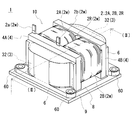
- FIG. 1 is a schematic perspective view of a reactor according to a first embodiment.
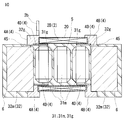
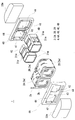
- FIG. 2 is a sectional view taken along the line II-II in FIG. It is a disassembled perspective view of the assembly shown in Embodiment 1 except an inner side resin part and an outer side resin part.
- FIG. 3 is a partially enlarged view of FIG. 2.
- It is a schematic front view of the combination shown in Embodiment 1 before forming an inner side resin part and an outer side resin part.
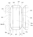
- It is a schematic perspective view of the core piece which comprises the inner core part shown in Embodiment 1.
- FIG. It is a schematic perspective view of the core piece of a form different from FIG.
- FIG. FIG. 9 is a sectional view taken along line IX-IX in FIG. 8.
- Patent Literature 1 when the gap portion is formed between the core pieces with the resin filled in the winding portion, the gap between the core pieces may not be sufficiently filled with the resin. If the resin filling between the core pieces is insufficient, the core pieces are likely to rattle inside the winding part, and noise is generated, the core pieces are in contact with each other, or the core piece is There is a risk of contact with the inner peripheral surface.
- an object of the present disclosure is to provide a reactor in which the resin is sufficiently filled between the core pieces even when the gap is formed between the core pieces with the resin filled in the winding part.
- the reactor of the embodiment is A magnet that forms a closed magnetic path with a coil having a winding part formed by winding a winding, an inner core part arranged inside the winding part, and an outer core part arranged outside the winding part
- a reactor comprising a core, An inner resin portion that joins the inner peripheral surface of the winding portion and the outer peripheral surface of the inner core portion;
- the inner core portion includes a plurality of core pieces and a gap portion constituted by a part of the inner resin portion,
- the core piece is A gap facing surface facing the gap portion; A coil facing surface facing the inner peripheral surface of the winding portion; A notch-shaped resin flow portion provided at a corner between the gap facing surface and the coil facing surface.
- the reactor provided with the resin flow part in the core piece is a reactor in which a large gap is not formed at the position of the gap part.
- the resin flow portion is made wider than the gap between the core pieces serving as gap portions, so that the resin serving as the inner resin portion is filled in the gap between the core pieces serving as gap portions when filling the inside of the winding portion. Becomes sufficiently easy to wrap around. As a result, it is difficult to form a large gap at the gap portion.
- Integrating the winding portion with the integrated resin can suppress the resin from leaking between the turns when filling the inside of the winding portion with the resin that becomes the inner resin portion. If the resin leakage from between the turns can be suppressed, the resin can easily sufficiently wrap around the gap between the core pieces to be the gap portion, and as a result, it is difficult to form a large gap at the position of the gap portion.
- the said core piece can mention the form which is a compacting body of a soft magnetic powder.
- a compacting body can be manufactured with high productivity by press-molding soft magnetic powder, the productivity of a reactor using the core piece of the compacting body can also be improved. Moreover, since the ratio of the soft magnetic powder which occupies for a core piece can be made high by comprising a core piece with a compacting body, the magnetic characteristic (relative magnetic permeability and saturation magnetic flux density) of a core piece can be improved. Therefore, the performance of the reactor using the core piece of the green compact can be improved.
- the said core piece can mention the form which is a composite material containing resin and the soft-magnetic powder disperse
- the composite material is easy to adjust the content of soft magnetic powder in the resin. Therefore, it is easy to adjust the performance of the reactor using the core piece of the composite material.
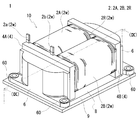
- a reactor 1 shown in FIG. 1 includes a combined body 10 in which a coil 2, a magnetic core 3, and an insulating interposed member 4 are combined, and a mounting plate 9 on which the combined body 10 is mounted.
- the combined body 10 further includes an inner resin portion 5 (see FIG. 2) disposed inside the winding portions 2 ⁇ / b> A and 2 ⁇ / b> B of the coil 2 and an outer resin portion that covers the outer core portion 32 constituting a part of the magnetic core 3. 6.
- each component with which the reactor 1 is provided is demonstrated in detail.
- the coil 2 of this example includes a single winding 2 w, and a pair of winding portions 2 ⁇ / b> A and 2 ⁇ / b> B and a connecting portion 2 ⁇ / b> R that connects both the winding portions 2 ⁇ / b> A and 2 ⁇ / b> B.
- Each winding part 2A, 2B is formed in a hollow cylindrical shape with the same number of turns and the same winding direction, and is arranged in parallel so that the respective axial directions are parallel. You may manufacture the coil 2 by connecting the winding parts 2A and 2B produced with the separate coil
- Each winding part 2A, 2B of this example is formed in a rectangular tube shape.
- the rectangular tube-shaped winding parts 2A and 2B are winding parts whose end face shape is a square shape (including a square shape) with rounded corners.
- the winding portions 2A and 2B may be formed in a cylindrical shape.
- the cylindrical winding portion is a winding portion whose end face shape is a closed curved surface shape (an elliptical shape, a perfect circle shape, a race track shape, etc.).
- the coil 2 including the winding portions 2A and 2B is a coated wire having an insulating coating made of an insulating material on the outer periphery of a conductor such as a flat wire or a round wire made of a conductive material such as copper, aluminum, magnesium, or an alloy thereof.
- a conductor such as a flat wire or a round wire made of a conductive material such as copper, aluminum, magnesium, or an alloy thereof.
- the conductor is made of a copper rectangular wire (winding 2w)
- the insulating coating is made of enamel (typically polyamideimide) by edgewise winding, whereby each winding portion 2A, 2B is formed.
- Both end portions 2a and 2b of the coil 2 are extended from the winding portions 2A and 2B and connected to a terminal member (not shown).
- the insulating coating such as enamel is peeled off at both ends 2a and 2b.
- An external device such as a power source for supplying power is connected to the coil 2 through the terminal member.
- the coil 2 having the above configuration is preferably integrated with resin as shown in FIG.
- the winding portions 2 ⁇ / b> A and 2 ⁇ / b> B of the coil 2 are individually integrated by the integrated resin 20.
- the integrated resin 20 of this example is configured by fusing a coating layer of heat-sealing resin formed on the outer periphery of the winding (further outer periphery of the insulating coating such as enamel), and is very thin. Therefore, even if winding part 2A, 2B is integrated with integral resin, the shape of the turn of winding part 2A, 2B and the boundary of a turn are in the state which can be understood from an external appearance.
- the material of the integrated resin 20 include resins that are fused by heat, for example, thermosetting resins such as epoxy resins, silicone resins, and unsaturated polyesters.
- the integrated resin 20 is exaggerated, but actually it is formed very thin.
- the integrated resin 20 integrates the turns constituting the winding part 2B (the same applies to the winding part 2A) and suppresses the expansion and contraction of the winding part 2B in the axial direction.
- the integrated resin 20 since the integrated resin 20 is formed by fusing the heat-sealing resin formed on the winding 2w, the integrated resin 20 uniformly enters the gaps between the turns.
- the thickness t1 of the integrated resin 20 between the turns is about twice the thickness of the heat-sealing resin formed on the surface of the winding 2w before winding, specifically, 20 ⁇ m or more and 2 mm or less. Can be mentioned. By increasing the thickness t1, the turns can be firmly integrated, and by reducing the thickness t1, it is possible to suppress the axial length of the winding portion 2B from becoming too long.
- the winding portions 2A and 2B of the rectangular tube-shaped coil 2 are divided into four corner portions formed by bending the winding 2w and a flat portion where the winding 2w is not bent. .
- the turns are integrated with the integrated resin 20 in the corner portions and flat portions of the winding portions 2 ⁇ / b> A and 2 ⁇ / b> B.
- the inner side of the bending tends to be thicker than the outer side of the bending.
- the winding portions 2A and 2B having a thick inside of the bend are heat-treated and the heat-sealing resin on the surface of the winding 2w is melted, the turns are integrated with the integrated resin 20 inside the bend. Each turn can be separated outside the bend.
- fusion resin exists in the outer periphery of the coil
- the magnetic core 3 is configured by combining a plurality of core pieces 31m and 32m, and can be divided into inner core portions 31 and 31 and outer core portions 32 and 32 for convenience (see FIGS. 1 and 2). See).
- the inner core part 31 is a part arrange
- the inner core portion 31 means a portion of the magnetic core 3 along the axial direction of the winding portions 2A and 2B of the coil 2.
- the end portions of the winding portions 2A and 2B along the axial direction protrude outside the winding portions 2A and 2B from the end surfaces of the winding portions 2A and 2B, but the protrusions protrude.
- the portion is also a part of the inner core portion 31.
- the inner core portion 31 of this example includes three core pieces 31m, a gap portion 31g formed between the core pieces 31m, and a gap portion 32g formed between the core piece 31m and a core piece 32m described later. And is composed of.
- the gap portions 31g and 32g in this example are formed by an inner resin portion 5 described later.
- the shape of the inner core portion 31 is a shape along the inner shape of the winding portion 2A (2B), and in the case of this example, is a substantially rectangular parallelepiped shape.
- the outer core portion 32 is a portion disposed outside the winding portions 2A and 2B, and has a shape connecting the ends of the pair of inner core portions 31 and 31 (see FIG. 1).
- the outer core portion 32 of the present example is composed of a columnar core piece 32m having a substantially dome shape on the upper and lower surfaces.
- the lower surface of the outer core portion 32 (the lower surface of the core piece 32m) is substantially flush with the lower surfaces of the winding portions 2A and 2B of the coil 2 (see FIG. 2).
- the core pieces 31m and 32m are compacted bodies formed by pressure-molding raw material powder containing soft magnetic powder.
- Soft magnetic powder is an aggregate of magnetic particles composed of an iron group metal such as iron or an alloy thereof (Fe—Si alloy, Fe—Ni alloy, etc.).
- the raw material powder may contain a lubricant.
- the core pieces 31m and 32m can be formed of a molded body of a composite material containing soft magnetic powder and resin.
- the soft magnetic powder and resin of the composite material the same soft magnetic powder and resin that can be used for the powder compact can be used.
- An insulating coating made of phosphate or the like may be formed on the surface of the magnetic particles.
- the core piece 31m of this example has a characteristic shape different from the conventional one.
- the characteristic shape will be described with reference to FIG. 4 (partially enlarged view of FIG. 2).
- the core piece 31m of this example includes a pair of gap facing surfaces 31X and 31X, and a coil facing surface 31Y facing the inner peripheral surface of the winding portion 2B (FIG. 2).
- the gap facing surface 31X on the right side of the paper is a surface facing the gap portion 31g formed between the adjacent core pieces 31m and 31m, and the gap facing surface 31X on the left side of the paper is the core facing 31m and the core piece. This is a surface facing the gap portion 32g formed between 32m (outer core portion 32).
- the core piece 31m of this example further includes a notch-shaped resin flow portion 31Z provided at a corner between the gap facing surface 31X and the coil facing surface 31Y.
- the resin flow part 31Z may be an inclined surface as shown or a curved surface. Since the resin flow part 31Z is formed, it is difficult to form a large gap in the gap parts 31g and 32g. In fact, no large gap is formed in the gap parts 31g and 32g of this example.
- the mechanism for suppressing the air gap by the resin flow part 31Z will be described in the item of the reactor manufacturing method.
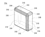
- the core piece 31m in FIG. 6 has a substantially rectangular parallelepiped shape, and includes flat surfaces 31A and 31B parallel to each other and four peripheral surfaces 31C to 31F.
- the core piece 31m when the flat surface 31A (31B) is viewed from the front, an inclined portion 31G that is inclined toward the peripheral surfaces 31C to 31F is formed over the entire outer periphery of the flat surface 31A (31B). (See the section shown with cross-hatching).
- the core piece 31m has a rounded portion 31H formed by rounding the ridge lines of the circumferential surfaces 31C, 31D (31D, 31E) (31E, 31F) (31F, 31C) adjacent in the circumferential direction (135 °). Indicated by diagonal hatching). 2 and 4, the core pieces 31m having such a configuration are arranged so that the flat surface 31A (31B) becomes the gap facing surface 31X. That is, the inclined portion 31G of the core piece 31m functions as the resin flow portion 31Z in FIG.
- the inclined portion 31G may have a curved shape.
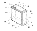
- the core piece 31m of the reactor 1 As the core piece 31m of the reactor 1, the core piece 31m having the shape shown in FIG. 7 can be used.
- the core piece 31m of FIG. 7 includes flat surfaces 31A and 31B, peripheral surfaces 31C to 31F, an inclined portion 31G, and a rounding portion 31H, similarly to the core piece 31m of FIG.
- the core piece 31m further includes an annular portion 31J that connects the inclined portion 31G and the peripheral surfaces 31C to 31F.
- the annular portion 31J is provided in parallel to the flat surface 31A (31B).
- the insulating intervening member 4 is a member that ensures insulation between the coil 2 and the magnetic core 3, and includes end surface interposing members 4 ⁇ / b> A and 4 ⁇ / b> B, inner interposing members 4 ⁇ / b> C and 4 ⁇ / b> D, It consists of
- the insulating interposition member 4 includes, for example, polyphenylene sulfide (PPS) resin, polytetrafluoroethylene (PTFE) resin, liquid crystal polymer (LCP), polyamide (PA) resin such as nylon 6 and nylon 66, polybutylene terephthalate (PBT) resin, It can be composed of a thermoplastic resin such as acrylonitrile / butadiene / styrene (ABS) resin.
- the insulating interposed member 4 can be formed of a thermosetting resin such as an unsaturated polyester resin, an epoxy resin, a urethane resin, or a silicone resin.
- the resin may contain a ceramic filler to improve the heat dissipation property of the insulating interposed member 4.
- the ceramic filler for example, nonmagnetic powder such as alumina or silica can be used.
- [[End face interposed member]] 3 is mainly used for the description of the end surface interposed members 4A and 4B.
- Two turn storage portions 41 for storing at least a part of the axial ends of the winding portions 2A and 2B are formed on the coil side surface of the end surface interposed members 4A and 4B (the turn of the end surface interposed member 4A). The storage is in an invisible position).
- the turn accommodating part 41 is formed to bring the entire axial end faces of the winding parts 2A and 2B into surface contact with the end face interposed member 4A.
- each turn storage part 41 is formed in a quadrangular annular shape surrounding the periphery of a through-hole 42 to be described later, and has an uneven shape corresponding to the unevenness of the end faces of the winding parts 2A and 2B.
- the end surface interposed members 4A and 4B include a pair of through holes 42 and 42 and a fitting portion 43 (see the end surface interposed member 4A) in addition to the turn storage portion 41 described above.
- the through hole 42 is a hole for fitting an assembly of the inner interposed members 4C and 4D and the core piece 31m.
- the fitting part 43 is a recessed part for fitting the core piece 32 m to be the outer core part 32.
- a stopper 44 for stopping the assembly is formed on the lower portion near the center of the through hole 42 and above the outer portion. By this stopper 44, the assembly is separated from the core piece 32m without being in direct contact.
- the side portion and the upper portion of the through hole 42 are recessed outward. As shown in FIG. 5, when the core piece 32m is fitted into the fitting portion 43 (FIG. 3) of the end surface interposing member 4A, the recessed portion is located at the position of the side edge and the upper edge of the core piece 32m.
- a resin filling hole 45 is formed.
- the resin filling hole 45 is a hole that penetrates in the thickness direction of the end surface interposed member 4A from the outer core portion 32 (core piece 32m) side in front of the paper surface toward the axial end surface side of the winding portions 2A and 2B on the back surface of the paper surface. Yes, it communicates with the space between the inner peripheral surface of the winding portions 2A and 2B and the outer peripheral surface of the inner core portion 31 (core piece 31m) on the back side of the paper (see also FIG. 2).
- the inner interposition members 4C and 4D When filling the winding portions 2A and 2B with the resin that becomes the inner resin portion 5 to be described later, the inner interposition members 4C and 4D set the interval between the adjacent core pieces 31m and 31m to a predetermined value, and the winding between the core piece 31m and the winding portion 2 There is no particular limitation as long as the distance between the turning portions 2A and 2B and the inner peripheral surface can be maintained at a predetermined value.
- the inner interposed members 4C and 4D in this example are bowl-shaped members having the same shape, and the inner interposed member 4D is formed by rotating the inner interposed member 4C in the 180 ° horizontal direction.
- the inside of the inner interposed members 4C and 4D is divided into three in the axial direction, and the core piece 31m can be accommodated in the divided portion.
- the core pieces 31m housed in the inner interposed members 4C and 4D are in a state of being separated from each other.
- the inner resin portion 5 is arranged inside a winding portion 2B (the same applies to the winding portion 2A not shown), and the inner peripheral surface of the winding portion 2B and the core piece 31m (the inner core portion 31). ).
- the winding portion 2B Since the winding portion 2B is integrated with the integrated resin 20 in the inner resin portion 5, the winding portion does not straddle between the inner peripheral surface and the outer peripheral surface of each turn of the winding portion 2B. It stays inside 2B. Further, a part of the inner resin portion 5 enters between the core piece 31m and the core piece 31m and between the core piece 31m and the core piece 32m to form gap portions 31g and 32g.
- the inner resin part 5 is, for example, a thermosetting resin such as an epoxy resin, a phenol resin, a silicone resin, or a urethane resin, a thermoplastic resin such as a PPS resin, a PA resin, a polyimide resin, or a fluorine resin, a room temperature curable resin, or A low temperature curable resin can be used. These resins may contain ceramic fillers such as alumina and silica to improve the heat dissipation of the inner resin portion 5.
- the inner resin portion 5 is preferably made of the same material as the end surface interposed members 4A and 4B and the inner interposed members 4C and 4D. By configuring the three members with the same material, the linear expansion coefficients of the three members can be made the same, and damage to each member due to thermal expansion / contraction can be suppressed.
- the outer resin portion 6 is disposed so as to cover the entire outer periphery of the core piece 32 m (outer core portion 32), and fixes the core piece 32 m to the end surface interposed members 4 ⁇ / b> A and 4 ⁇ / b> B.
- the piece 32m is protected from the external environment.
- the lower surface of the core piece 32 m may be exposed from the outer resin portion 6. In that case, it is preferable to extend the lower part of the core piece 32m so as to be substantially flush with the lower surfaces of the end surface interposed members 4A and 4B.
- a magnetic core including the core piece 32m by bringing the lower surface of the core piece 32m into direct contact with the mounting plate 9 to be described later, or by interposing an adhesive or an insulating sheet between the mounting plate 9 and the lower surface of the core piece 32m.
- the heat dissipation of 3 can be improved.
- the outer resin portion 6 of this example is provided on the side where the core piece 32m is disposed in the end surface interposed members 4A and 4B, and does not reach the outer peripheral surface of the winding portions 2A and 2B.
- the formation range of the outer resin portion 6 is sufficient as shown in the figure, and is preferable in that the amount of resin used can be reduced.
- the outer resin portion 6 may extend to the winding portions 2A and 2B.
- the outer resin portion 6 of this example is connected to the inner resin portion 5 through the resin filling holes 45 of the end surface interposed members 4A and 4B. That is, the outer resin part 6 and the inner resin part 5 are formed of the same resin at a time. Unlike this example, the outer resin part 6 and the inner resin part 5 can be formed separately.
- the outer resin portion 6 can be made of a resin similar to the resin that can be used for forming the inner resin portion 5. When the outer resin part 6 and the inner resin part 5 are connected as in this example, both the resin parts 6 and 5 are made of the same resin.
- the outer resin portion 6 is formed with a fixing portion 60 (see FIG. 1) for fixing the assembly 10 to the mounting plate 9 or the like.
- a fixing portion 60 for fixing the assembly 10 to the mounting plate 9 or the like.
- the reactor 1 of the present embodiment further includes a mounting plate 9 on which the combined body 10 is mounted. Between the mounting plate 9 and the combined body 10, a bonding layer 8 for bonding the both 9 and 10 is formed.
- the mounting plate 9 is preferably made of a material having excellent mechanical strength and thermal conductivity, and can be made of, for example, aluminum or an alloy thereof.
- the bonding layer 8 is preferably made of a material having excellent insulating properties, and can be made of, for example, a thermosetting resin such as epoxy resin, silicone resin, or unsaturated polyester, or a thermoplastic resin such as PPS resin or LCP. . You may improve the heat dissipation of the joining layer 8 by making these insulating resins contain a ceramic filler.
- the reactor manufacturing method generally includes the following steps. Refer to FIG. 3 mainly in description of the manufacturing method of a reactor. ⁇ Coil manufacturing process ⁇ Integration process ⁇ Assembly process ⁇ Filling process ⁇ Curing process
- the coil 2 is produced by preparing the winding 2w and winding a part of the winding 2w.
- a known winding machine can be used for winding the winding 2w.
- a coating layer of the heat-sealing resin that becomes the integrated resin 20 described with reference to FIG. 2 can be formed. The thickness of the coating layer can be appropriately selected.
- the winding portions 2A and 2B are integrated with the integrated resin 20 (see FIG. 2).
- the integrated resin 20 can be formed by heat-treating the coil 2.
- a resin is applied to the outer periphery and inner periphery of the winding portions 2A and 2B of the coil 2, and the resin is cured, thereby integrating the resin 20 It is good to form.
- This integration step can also be performed after the assembly step described below and before the filling step.
- the coil 2, the core pieces 31 m and 32 m constituting the magnetic core 3, and the insulating interposed member 4 are combined.
- a first assembly in which the core pieces 31m are arranged in the storage portions of the inner interposed members 4C and 4D is manufactured, and the first assembly is arranged inside the winding portions 2A and 2B.
- the end surface interposing members 4A and 4B are brought into contact with the one end side end surface and the other end side end surface in the axial direction of the winding portions 2A and 2B and sandwiched between the pair of core pieces 32m, and the coil 2 and the core pieces 31m and 32m
- the 2nd assembly which combined the insulating interposition member 4 is produced.
- the side and upper edges of the core piece 32m are formed.
- the resin filling hole 45 is formed by a gap between the through hole 42 of the end surface interposed members 4A and 4B and the outer core portion 32 fitted in the fitting portion 43 (see also FIG. 3).
- the resin is filled into the winding parts 2A and 2B in the second assembly.
- the second assembly is placed in a mold, and injection molding is performed in which a resin is injected into the mold.
- the resin is injected from the end face side (the opposite side of the coil 2) of one of the core pieces 32m.
- the resin filled in the mold covers the outer periphery of the core piece 32m and flows into the winding portions 2A and 2B through the resin filling holes 45 (FIGS. 2 and 5). In that case, the air in winding part 2A, 2B is exhausted outside from the resin filling hole 45 by the side of the other core piece 32m.
- the resin filled in the winding parts 2A and 2B not only enters between the inner peripheral surface of the winding part 2B and the outer peripheral surface of the core piece 31m, but also two adjacent ones.
- the gaps 31g and 32g are formed between the core pieces 31m and 31m and between the core piece 31m and the outer core part 32 (core piece 32m).
- the resin flow part 31Z is formed in the core piece 31m of this example as shown in FIG. 4, the gap between the core piece 31m and the core piece 31m, and the core piece 31m and the core piece 32m
- the resin is easy to enter the gap. For this reason, the gap is not sufficiently filled with the resin, and it is difficult to form large gaps in the gap portions 31g and 32g, or not formed at all.
- the gap part 31g (32g) As shown in FIG. 4, by making the width W of the resin flow part 31Z wider than the interval between the core pieces 31m, 32m (31m, 32m) to be the gap part 31g (32g), the gap part 31g (32g) It becomes easy for the resin to go into the gap between the core pieces 31m and 32m (31m and 32m).
- the resin filled in the winding portions 2A and 2B from the resin filling hole 45 by applying pressure by injection molding is sufficiently distributed in the narrow gap between the winding portions 2A and 2B and the inner core portion 31, but the winding portion There is almost no leakage to the outside of 2A and 2B.
- the axial end surface of the winding portion 2 ⁇ / b> B and the end surface interposed members 4 ⁇ / b> A and 4 ⁇ / b> B are in surface contact, and the winding portion 2 ⁇ / b> B is integrated with the integrated resin 20.
- the turns are integrated at the corners of the bending of the rectangular cylindrical winding parts 2A and 2B, and a minute gap is formed in the flat part.
- the resin can be filled from both the outside of the one core piece 32m and the outside of the other core piece 32m. In that case, it exhausts out of winding part 2A, 2B from the micro clearance gap formed in a flat part. Due to the viscosity and surface tension of the resin, the resin hardly leaks outside the winding portions 2A and 2B through a minute gap in the flat portion.
- the resin is cured by heat treatment or time passage.
- the one inside the winding parts 2A and 2B is the inner resin part 5 as shown in FIG. 2, and the one covering the core piece 32m is the outer resin part 6.
- the combined body 10 of the reactor 1 shown in FIG. 1 can be manufactured.
- the filling process and the curing process are performed only once, so that the assembly 10 can be manufactured with high productivity.
- the completed assembly 10 may be fixed on the mounting plate 9 via the bonding layer 8.
- the outer periphery of winding part 2A, 2B of the coil 2 is not molded with resin, it is in the state of being directly exposed to the external environment. It becomes the reactor 1 excellent in property. If the combination 10 of the reactor 1 is immersed in the liquid refrigerant, the heat dissipation of the reactor 1 can be further improved.
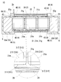
- the reactor 1 of the second embodiment includes winding portions 2A and 2B having a longer axial length than the winding portions 2A and 2B of the reactor 1 of the first embodiment.
- the inner core portion 31 is formed by horizontally connecting the core pieces 31 m having a thickness larger than that of the core pieces 31 m of FIG. 6. More specifically, as shown in the encircled enlarged view of FIG. 9, the core piece 31m is arranged such that the flat surface 31A of the core piece 31m faces in a direction (front side of the sheet) perpendicular to the axial direction of the winding portion 2B. Are arranged (see also FIG. 6).
- the peripheral surface 31F of the core piece 31m is a gap facing surface 31X that faces the gap portion 31g, and the flat surface 31A and the peripheral surface 31E are coil facing surfaces 31Y.
- the inclined portion 31G and the rounded portion 31H form a resin flow portion 31Z.
- the core piece 31m in which the thickness of the core piece 31m in FIG. 7 is increased can also be used.
- the reactor according to each embodiment can be used as a component of a power conversion device such as a bidirectional DC-DC converter mounted on an electric vehicle such as a hybrid vehicle, an electric vehicle, or a fuel cell vehicle.
- a power conversion device such as a bidirectional DC-DC converter mounted on an electric vehicle such as a hybrid vehicle, an electric vehicle, or a fuel cell vehicle.
Landscapes
- Engineering & Computer Science (AREA)
- Power Engineering (AREA)
- Manufacturing & Machinery (AREA)
- Chemical & Material Sciences (AREA)
- Composite Materials (AREA)
- Insulating Of Coils (AREA)
Abstract
A reactor that comprises: a coil that has a wound section that is formed by winding a winding; a magnetic core that forms a closed magnetic circuit by means of an inside core section that is arranged inside the wound section and an outside core section that is arranged outside the wound section; and an inside resin section that joins an inner peripheral surface of the wound section and an outer peripheral surface of the inside core section. The inside core section comprises a gap section that is configured from a plurality of core pieces and one section of the inside resin section. The core pieces comprise: a gap-facing surface that faces the gap section; a coil-facing surface that faces the inner peripheral surface of the wound section; and a notch-shaped resin flow section that is provided at a corner section that is between the gap-facing surface and the coil-facing surface.
Description
本発明は、リアクトルに関する。
本出願は、2016年2月3日付の日本国出願の特願2016-019195に基づく優先権を主張し、前記日本国出願に記載された全ての記載内容を援用するものである。 The present invention relates to a reactor.
This application claims priority based on Japanese Patent Application No. 2016-0119195 filed on Feb. 3, 2016, and incorporates all the contents described in the aforementioned Japanese application.
特許文献1には、コイルと磁性コアと絶縁介在部材とを組み合わせた後、コイルの巻回部の内部に樹脂を充填したリアクトルが開示されている。このような構成とすることで、磁性コアを構成する複数のコア片を樹脂で被覆し、その被覆コア片をコイルと組み合わせるよりも、リアクトルの製造工程を簡素化できると考えられる。
Patent Document 1 discloses a reactor in which a coil, a magnetic core, and an insulating intervening member are combined, and then a coil is wound with resin inside. By adopting such a configuration, it is considered that the manufacturing process of the reactor can be simplified rather than coating a plurality of core pieces constituting the magnetic core with a resin and combining the coated core pieces with a coil.
本開示のリアクトルは、
巻線を巻回してなる巻回部を有するコイルと、前記巻回部の内部に配置される内側コア部と前記巻回部の外部に配置される外側コア部とで閉磁路を形成する磁性コアと、を備えるリアクトルであって、
前記巻回部の内周面と前記内側コア部の外周面とを接合する内側樹脂部を備え、
前記内側コア部は、複数のコア片と前記内側樹脂部の一部で構成されるギャップ部とを備え、
前記コア片は、
前記ギャップ部に対向するギャップ対向面と、
前記巻回部の内周面に対向するコイル対向面と、
前記ギャップ対向面と前記コイル対向面との角部に設けられた切欠き状の樹脂流れ部と、を備える。 The reactor of the present disclosure is
A magnet that forms a closed magnetic path by a coil having a winding part formed by winding a winding, an inner core part arranged inside the winding part, and an outer core part arranged outside the winding part A reactor comprising a core,
An inner resin portion that joins the inner peripheral surface of the winding portion and the outer peripheral surface of the inner core portion;
The inner core portion includes a plurality of core pieces and a gap portion constituted by a part of the inner resin portion,
The core piece is
A gap facing surface facing the gap portion;
A coil facing surface facing the inner peripheral surface of the winding portion;
A notch-shaped resin flow portion provided at a corner between the gap facing surface and the coil facing surface.
[本開示が解決しようとする課題]
特許文献1の構成では、巻回部の内部に充填した樹脂でコア片間にギャップ部を形成する場合、コア片間の隙間に十分に樹脂を充填することができない場合がある。コア片間への樹脂の充填が不十分であると、巻回部の内部でコア片ががたつき易く、騒音が発生したり、コア片同士が接触したり、コア片が巻回部の内周面に接触したりする虞がある。 [Problems to be solved by the present disclosure]
In the configuration ofPatent Literature 1, when the gap portion is formed between the core pieces with the resin filled in the winding portion, the gap between the core pieces may not be sufficiently filled with the resin. If the resin filling between the core pieces is insufficient, the core pieces are likely to rattle inside the winding part, and noise is generated, the core pieces are in contact with each other, or the core piece is There is a risk of contact with the inner peripheral surface.
特許文献1の構成では、巻回部の内部に充填した樹脂でコア片間にギャップ部を形成する場合、コア片間の隙間に十分に樹脂を充填することができない場合がある。コア片間への樹脂の充填が不十分であると、巻回部の内部でコア片ががたつき易く、騒音が発生したり、コア片同士が接触したり、コア片が巻回部の内周面に接触したりする虞がある。 [Problems to be solved by the present disclosure]
In the configuration of
そこで、本開示は、巻回部の内部に充填した樹脂でコア片間にギャップ部を形成した場合でもコア片間に十分に樹脂が充填されたリアクトルを提供することを目的の一つとする。
Therefore, an object of the present disclosure is to provide a reactor in which the resin is sufficiently filled between the core pieces even when the gap is formed between the core pieces with the resin filled in the winding part.
[本開示の効果]
本開示のリアクトルによれば、巻回部の内部に充填した樹脂でコア片間にギャップ部を形成した場合でも、コア片間に十分に樹脂(内側樹脂部)が充填されたリアクトルとすることができる。 [Effects of the present disclosure]
According to the reactor of the present disclosure, even when the gap portion is formed between the core pieces with the resin filled in the winding portion, the reactor is sufficiently filled with the resin (inner resin portion) between the core pieces. Can do.
[本願発明の実施形態の説明]
最初に本願発明の実施態様を列記して説明する。 [Description of Embodiment of Present Invention]
First, embodiments of the present invention will be listed and described.
最初に本願発明の実施態様を列記して説明する。 [Description of Embodiment of Present Invention]
First, embodiments of the present invention will be listed and described.
<1>実施形態のリアクトルは、
巻線を巻回してなる巻回部を有するコイルと、前記巻回部の内部に配置される内側コア部と前記巻回部の外部に配置される外側コア部とで閉磁路を形成する磁性コアと、を備えるリアクトルであって、
前記巻回部の内周面と前記内側コア部の外周面とを接合する内側樹脂部を備え、
前記内側コア部は、複数のコア片と前記内側樹脂部の一部で構成されるギャップ部とを備え、
前記コア片は、
前記ギャップ部に対向するギャップ対向面と、
前記巻回部の内周面に対向するコイル対向面と、
前記ギャップ対向面と前記コイル対向面との角部に設けられた切欠き状の樹脂流れ部と、を備える。 <1> The reactor of the embodiment is
A magnet that forms a closed magnetic path with a coil having a winding part formed by winding a winding, an inner core part arranged inside the winding part, and an outer core part arranged outside the winding part A reactor comprising a core,
An inner resin portion that joins the inner peripheral surface of the winding portion and the outer peripheral surface of the inner core portion;
The inner core portion includes a plurality of core pieces and a gap portion constituted by a part of the inner resin portion,
The core piece is
A gap facing surface facing the gap portion;
A coil facing surface facing the inner peripheral surface of the winding portion;
A notch-shaped resin flow portion provided at a corner between the gap facing surface and the coil facing surface.
コア片のギャップ対向面とコイル対向面との角部に樹脂流れ部を形成することで、内側樹脂部となる樹脂を巻回部の内部に充填する際、ギャップ部となるコア片間の隙間(コア片と外側コア部との隙間を含む)に樹脂が十分に回り込み易くなる。その結果、リアクトルにおけるギャップ部の位置に大きな空隙が形成され難くなる。つまり、コア片に樹脂流れ部を備えるリアクトルは、ギャップ部の位置に大きな空隙が形成されていないリアクトルとなる。
By forming a resin flow part at the corner between the gap facing surface and the coil facing surface of the core piece, when filling the inside of the winding part with the resin that becomes the inner resin part, the gap between the core pieces that become the gap part The resin is sufficiently easily wrapped around (including the gap between the core piece and the outer core portion). As a result, it is difficult to form a large gap at the position of the gap portion in the reactor. That is, the reactor provided with the resin flow part in the core piece is a reactor in which a large gap is not formed at the position of the gap part.
<2>実施形態のリアクトルとして、
前記ギャップ対向面の外周縁部の全周に亘って前記樹脂流れ部が形成されている形態を挙げることができる。 <2> As the reactor of the embodiment,
The form which the said resin flow part is formed over the perimeter of the outer peripheral edge part of the said gap opposing surface can be mentioned.
前記ギャップ対向面の外周縁部の全周に亘って前記樹脂流れ部が形成されている形態を挙げることができる。 <2> As the reactor of the embodiment,
The form which the said resin flow part is formed over the perimeter of the outer peripheral edge part of the said gap opposing surface can be mentioned.
コア片のギャップ対向面の外周縁部の全周に亘って樹脂流れ部を形成することで、内側樹脂部となる樹脂を巻回部の内側に充填する際、ギャップ部となるコア片間の隙間に樹脂が十分に回り込み易くなる。その結果、リアクトルにおけるギャップ部の位置に大きな空隙が形成され難くなる。
By forming the resin flow part over the entire circumference of the outer peripheral edge of the gap facing surface of the core piece, when filling the resin that becomes the inner resin part inside the winding part, between the core pieces that become the gap part It becomes easy for the resin to sufficiently wrap around the gap. As a result, it is difficult to form a large gap at the position of the gap portion in the reactor.
<3>実施形態のリアクトルとして、
前記巻回部の軸方向に直交する方向から見たとき、前記樹脂流れ部の幅が前記ギャップ部の幅よりも広い形態を挙げることができる。 <3> As the reactor of the embodiment,
When viewed from a direction orthogonal to the axial direction of the winding part, a form in which the width of the resin flow part is wider than the width of the gap part can be exemplified.
前記巻回部の軸方向に直交する方向から見たとき、前記樹脂流れ部の幅が前記ギャップ部の幅よりも広い形態を挙げることができる。 <3> As the reactor of the embodiment,
When viewed from a direction orthogonal to the axial direction of the winding part, a form in which the width of the resin flow part is wider than the width of the gap part can be exemplified.
ギャップ部となるコア片間の間隔よりも樹脂流れ部の幅を広くすることで、内側樹脂部となる樹脂を巻回部の内側に充填する際、ギャップ部となるコア片間の隙間に樹脂が十分に回り込み易くなる。その結果、ギャップ部の位置に大きな空隙が形成され難くなる。
The resin flow portion is made wider than the gap between the core pieces serving as gap portions, so that the resin serving as the inner resin portion is filled in the gap between the core pieces serving as gap portions when filling the inside of the winding portion. Becomes sufficiently easy to wrap around. As a result, it is difficult to form a large gap at the gap portion.
<4>実施形態のリアクトルとして、
前記コイルは、前記内側樹脂部とは別に設けられ、前記巻回部の各ターンを一体化させる一体化樹脂を備える形態を挙げることができる。 <4> As the reactor of the embodiment,
The said coil is provided separately from the said inner side resin part, The form provided with the integrated resin which integrates each turn of the said winding part can be mentioned.
前記コイルは、前記内側樹脂部とは別に設けられ、前記巻回部の各ターンを一体化させる一体化樹脂を備える形態を挙げることができる。 <4> As the reactor of the embodiment,
The said coil is provided separately from the said inner side resin part, The form provided with the integrated resin which integrates each turn of the said winding part can be mentioned.
一体化樹脂で巻回部を一体化することで、内側樹脂部となる樹脂を巻回部の内部に充填する際、ターン間から樹脂が漏れることを抑制することができる。ターン間からの樹脂漏れを抑制できれば、ギャップ部となるコア片間の隙間に樹脂が十分に回り込み易く、その結果、ギャップ部の位置に大きな空隙が形成され難くなる。
Integrating the winding portion with the integrated resin can suppress the resin from leaking between the turns when filling the inside of the winding portion with the resin that becomes the inner resin portion. If the resin leakage from between the turns can be suppressed, the resin can easily sufficiently wrap around the gap between the core pieces to be the gap portion, and as a result, it is difficult to form a large gap at the position of the gap portion.
<5>実施形態のリアクトルとして、
前記コア片は、軟磁性粉末の圧粉成形体である形態を挙げることができる。 <5> As the reactor of the embodiment,
The said core piece can mention the form which is a compacting body of a soft magnetic powder.
前記コア片は、軟磁性粉末の圧粉成形体である形態を挙げることができる。 <5> As the reactor of the embodiment,
The said core piece can mention the form which is a compacting body of a soft magnetic powder.
圧粉成形体は、軟磁性粉末を加圧成形することで生産性良く製造することができるので、この圧粉成形体のコア片を用いたリアクトルの生産性も向上することができる。また、コア片を圧粉成形体で構成することで、コア片に占める軟磁性粉末の割合を高くできるので、コア片の磁気特性(比透磁率や飽和磁束密度)を高めることができる。そのため、圧粉成形体のコア片を用いたリアクトルの性能を向上させることができる。
Since a compacting body can be manufactured with high productivity by press-molding soft magnetic powder, the productivity of a reactor using the core piece of the compacting body can also be improved. Moreover, since the ratio of the soft magnetic powder which occupies for a core piece can be made high by comprising a core piece with a compacting body, the magnetic characteristic (relative magnetic permeability and saturation magnetic flux density) of a core piece can be improved. Therefore, the performance of the reactor using the core piece of the green compact can be improved.
<6>実施形態のリアクトルとして、
前記コア片は、樹脂と、前記樹脂中に分散した軟磁性粉末と、を含む複合材料である形態を挙げることができる。 <6> As the reactor of the embodiment,
The said core piece can mention the form which is a composite material containing resin and the soft-magnetic powder disperse | distributed in the said resin.
前記コア片は、樹脂と、前記樹脂中に分散した軟磁性粉末と、を含む複合材料である形態を挙げることができる。 <6> As the reactor of the embodiment,
The said core piece can mention the form which is a composite material containing resin and the soft-magnetic powder disperse | distributed in the said resin.
複合材料は、樹脂中の軟磁性粉末の含有量を調整し易い。そのため、複合材料のコア片を用いたリアクトルの性能を調整し易い。
The composite material is easy to adjust the content of soft magnetic powder in the resin. Therefore, it is easy to adjust the performance of the reactor using the core piece of the composite material.
[本願発明の実施形態の詳細]
以下、本願発明のリアクトルの実施形態を図面に基づいて説明する。図中の同一符号は同一名称物を示す。なお、本願発明は実施形態に示される構成に限定されるわけではなく、請求の範囲によって示され、請求の範囲と均等の意味および範囲内の全ての変更が含まれることを意図する。 [Details of the embodiment of the present invention]
Hereinafter, an embodiment of a reactor of the present invention will be described based on the drawings. The same reference numerals in the figure indicate the same names. Note that the present invention is not limited to the configuration shown in the embodiment, but is shown by the scope of claims and is intended to include meanings equivalent to the scope of claims and all modifications within the scope.
<実施形態1>
実施形態1では、図1~図7に基づいてリアクトル1の構成を説明する。図1に示すリアクトル1は、コイル2と磁性コア3と絶縁介在部材4とを組み合わせた組合体10と、組合体10を載置する載置板9と、を備える。組合体10はさらに、コイル2の巻回部2A,2Bの内部に配置される内側樹脂部5(図2参照)と、磁性コア3の一部を構成する外側コア部32を覆う外側樹脂部6と、を備える。以下、リアクトル1に備わる各構成を詳細に説明する。 <Embodiment 1>
In the first embodiment, the configuration of thereactor 1 will be described based on FIGS. 1 to 7. A reactor 1 shown in FIG. 1 includes a combined body 10 in which a coil 2, a magnetic core 3, and an insulating interposed member 4 are combined, and a mounting plate 9 on which the combined body 10 is mounted. The combined body 10 further includes an inner resin portion 5 (see FIG. 2) disposed inside the winding portions 2 </ b> A and 2 </ b> B of the coil 2 and an outer resin portion that covers the outer core portion 32 constituting a part of the magnetic core 3. 6. Hereinafter, each component with which the reactor 1 is provided is demonstrated in detail.
実施形態1では、図1~図7に基づいてリアクトル1の構成を説明する。図1に示すリアクトル1は、コイル2と磁性コア3と絶縁介在部材4とを組み合わせた組合体10と、組合体10を載置する載置板9と、を備える。組合体10はさらに、コイル2の巻回部2A,2Bの内部に配置される内側樹脂部5(図2参照)と、磁性コア3の一部を構成する外側コア部32を覆う外側樹脂部6と、を備える。以下、リアクトル1に備わる各構成を詳細に説明する。 <
In the first embodiment, the configuration of the
≪組合体≫
コイル2、磁性コア3、および絶縁介在部材4を備える組合体10の説明には主として図3の分解斜視図、および図2の概略縦断面図を用いる。図2では、コア片31mは断面ではなく、側面を示している(この点は、図9においても同様)。 ≪Union body≫
For the description of the combinedbody 10 including the coil 2, the magnetic core 3, and the insulating interposed member 4, the exploded perspective view of FIG. 3 and the schematic longitudinal sectional view of FIG. 2 are mainly used. In FIG. 2, the core piece 31m shows a side surface instead of a cross section (this also applies to FIG. 9).
コイル2、磁性コア3、および絶縁介在部材4を備える組合体10の説明には主として図3の分解斜視図、および図2の概略縦断面図を用いる。図2では、コア片31mは断面ではなく、側面を示している(この点は、図9においても同様)。 ≪Union body≫
For the description of the combined
[コイル]
図3に示すように、本例のコイル2は、一本の巻線2wで構成されており、一対の巻回部2A,2Bと、両巻回部2A,2Bを連結する連結部2Rと、を備える。各巻回部2A,2Bは、互いに同一の巻数、同一の巻回方向で中空筒状に形成され、各軸方向が平行になるように並列されている。別々の巻線により作製した巻回部2A,2Bを連結することでコイル2を製造しても良い。 [coil]
As shown in FIG. 3, thecoil 2 of this example includes a single winding 2 w, and a pair of winding portions 2 </ b> A and 2 </ b> B and a connecting portion 2 </ b> R that connects both the winding portions 2 </ b> A and 2 </ b> B. . Each winding part 2A, 2B is formed in a hollow cylindrical shape with the same number of turns and the same winding direction, and is arranged in parallel so that the respective axial directions are parallel. You may manufacture the coil 2 by connecting the winding parts 2A and 2B produced with the separate coil | winding.
図3に示すように、本例のコイル2は、一本の巻線2wで構成されており、一対の巻回部2A,2Bと、両巻回部2A,2Bを連結する連結部2Rと、を備える。各巻回部2A,2Bは、互いに同一の巻数、同一の巻回方向で中空筒状に形成され、各軸方向が平行になるように並列されている。別々の巻線により作製した巻回部2A,2Bを連結することでコイル2を製造しても良い。 [coil]
As shown in FIG. 3, the
本例の各巻回部2A,2Bは角筒状に形成されている。角筒状の巻回部2A,2Bとは、その端面形状が四角形状(正方形状を含む)の角を丸めた形状の巻回部のことである。もちろん、巻回部2A,2Bは円筒状に形成しても構わない。円筒状の巻回部とは、その端面形状が閉曲面形状(楕円形状や真円形状、レーストラック形状など)の巻回部のことである。
Each winding part 2A, 2B of this example is formed in a rectangular tube shape. The rectangular tube-shaped winding parts 2A and 2B are winding parts whose end face shape is a square shape (including a square shape) with rounded corners. Of course, the winding portions 2A and 2B may be formed in a cylindrical shape. The cylindrical winding portion is a winding portion whose end face shape is a closed curved surface shape (an elliptical shape, a perfect circle shape, a race track shape, etc.).
巻回部2A,2Bを含むコイル2は、銅やアルミニウム、マグネシウム、あるいはその合金といった導電性材料からなる平角線や丸線などの導体の外周に、絶縁性材料からなる絶縁被覆を備える被覆線によって構成することができる。本実施形態では、導体が銅製の平角線(巻線2w)からなり、絶縁被覆がエナメル(代表的にはポリアミドイミド)からなる被覆平角線をエッジワイズ巻きにすることで、各巻回部2A,2Bを形成している。
The coil 2 including the winding portions 2A and 2B is a coated wire having an insulating coating made of an insulating material on the outer periphery of a conductor such as a flat wire or a round wire made of a conductive material such as copper, aluminum, magnesium, or an alloy thereof. Can be configured. In this embodiment, the conductor is made of a copper rectangular wire (winding 2w), and the insulating coating is made of enamel (typically polyamideimide) by edgewise winding, whereby each winding portion 2A, 2B is formed.
コイル2の両端部2a,2bは、巻回部2A,2Bから引き延ばされて、図示しない端子部材に接続される。両端部2a,2bではエナメルなどの絶縁被覆は剥がされている。この端子部材を介して、コイル2に電力供給を行なう電源などの外部装置が接続される。
Both end portions 2a and 2b of the coil 2 are extended from the winding portions 2A and 2B and connected to a terminal member (not shown). The insulating coating such as enamel is peeled off at both ends 2a and 2b. An external device such as a power source for supplying power is connected to the coil 2 through the terminal member.
上記構成を備えるコイル2は、図2に示すように樹脂によって一体化されていることが好ましい。本例の場合、コイル2の巻回部2A,2Bはそれぞれ、一体化樹脂20によって個別に一体化されている。本例の一体化樹脂20は、巻線の外周(エナメルなどの絶縁被覆のさらに外周)に形成される熱融着樹脂の被覆層を融着させることで構成されており、非常に薄い。そのため、巻回部2A,2Bが一体化樹脂で一体化されていても、巻回部2A,2Bのターンの形状や、ターンの境界が外観上から分かる状態になっている。一体化樹脂20の材質としては、熱によって融着する樹脂、例えば、エポキシ樹脂、シリコーン樹脂、不飽和ポリエステルなどの熱硬化性樹脂を挙げることができる。
The coil 2 having the above configuration is preferably integrated with resin as shown in FIG. In the case of this example, the winding portions 2 </ b> A and 2 </ b> B of the coil 2 are individually integrated by the integrated resin 20. The integrated resin 20 of this example is configured by fusing a coating layer of heat-sealing resin formed on the outer periphery of the winding (further outer periphery of the insulating coating such as enamel), and is very thin. Therefore, even if winding part 2A, 2B is integrated with integral resin, the shape of the turn of winding part 2A, 2B and the boundary of a turn are in the state which can be understood from an external appearance. Examples of the material of the integrated resin 20 include resins that are fused by heat, for example, thermosetting resins such as epoxy resins, silicone resins, and unsaturated polyesters.
図2では一体化樹脂20を誇張して示しているが、実際には非常に薄く形成されている。一体化樹脂20は、巻回部2B(巻回部2Aでも同様)を構成する各ターンを一体化し、巻回部2Bの軸方向の伸縮を抑制する。本例では、巻線2wに形成される熱融着樹脂を融着させて一体化樹脂20を形成しているため、各ターン間の隙間にも均一的に一体化樹脂20が入り込んでいる。ターン間における一体化樹脂20の厚さt1は、巻回前の巻線2wの表面に形成される熱融着樹脂の厚さの約二倍であり、具体的には20μm以上2mm以下とすることが挙げられる。厚さt1を厚くすることで、各ターンを強固に一体化させることができ、厚さt1を薄くすることで巻回部2Bの軸方向長さが長くなり過ぎることを抑制できる。
In FIG. 2, the integrated resin 20 is exaggerated, but actually it is formed very thin. The integrated resin 20 integrates the turns constituting the winding part 2B (the same applies to the winding part 2A) and suppresses the expansion and contraction of the winding part 2B in the axial direction. In this example, since the integrated resin 20 is formed by fusing the heat-sealing resin formed on the winding 2w, the integrated resin 20 uniformly enters the gaps between the turns. The thickness t1 of the integrated resin 20 between the turns is about twice the thickness of the heat-sealing resin formed on the surface of the winding 2w before winding, specifically, 20 μm or more and 2 mm or less. Can be mentioned. By increasing the thickness t1, the turns can be firmly integrated, and by reducing the thickness t1, it is possible to suppress the axial length of the winding portion 2B from becoming too long.
ここで、角筒状のコイル2の巻回部2A,2Bは、巻線2wが曲げられることで形成される四つの角部と、巻線2wが曲げられていない平坦部と、に分けられる。図1,2では巻回部2A,2Bの角部においても平坦部においても各ターン同士を一体化樹脂20で一体化した構成である。これに対して、巻回部2A,2Bの一部、例えば角部においてのみ各ターン同士が一体化樹脂20で一体化されている構成としても良い。
Here, the winding portions 2A and 2B of the rectangular tube-shaped coil 2 are divided into four corner portions formed by bending the winding 2w and a flat portion where the winding 2w is not bent. . In FIGS. 1 and 2, the turns are integrated with the integrated resin 20 in the corner portions and flat portions of the winding portions 2 </ b> A and 2 </ b> B. On the other hand, it is good also as a structure by which each turn is integrated with the integrated resin 20 only in part of winding part 2A, 2B, for example, a corner | angular part.
巻線2wをエッジワイズ巻きすることで形成される巻回部2A,2Bの角部では、曲げの内側が曲げの外側よりも厚くなり易い。このような曲げの内側が厚くなった巻回部2A,2Bを熱処理し、巻線2w表面の熱融着樹脂を溶融させると、曲げの内側では各ターンを一体化樹脂20で一体化させることができ、曲げの外側では各ターンを離隔させることができる。この場合、巻回部2A,2Bの平坦部では、巻線2wの外周に熱融着樹脂があるが、各ターン間は一体化されずに離隔する。この平坦部における隙間が十分に小さければ、巻回部2A,2Bの内部に樹脂を充填してもその樹脂は表面張力によって平坦部の隙間を通過できない。
At the corners of the winding portions 2A and 2B formed by edgewise winding the winding 2w, the inner side of the bending tends to be thicker than the outer side of the bending. When the winding portions 2A and 2B having a thick inside of the bend are heat-treated and the heat-sealing resin on the surface of the winding 2w is melted, the turns are integrated with the integrated resin 20 inside the bend. Each turn can be separated outside the bend. In this case, in the flat part of winding part 2A, 2B, although heat sealing | fusion resin exists in the outer periphery of the coil | winding 2w, it is spaced apart without integrating between each turn. If the gap in the flat portion is sufficiently small, the resin cannot pass through the gap in the flat portion due to surface tension even if the winding portions 2A and 2B are filled with resin.
[磁性コア]
磁性コア3は、複数のコア片31m,32mを組み合わせて構成されており、便宜上、内側コア部31,31と、外側コア部32,32と、に分けることができる(図1,2を合わせて参照)。 [Magnetic core]
Themagnetic core 3 is configured by combining a plurality of core pieces 31m and 32m, and can be divided into inner core portions 31 and 31 and outer core portions 32 and 32 for convenience (see FIGS. 1 and 2). See).
磁性コア3は、複数のコア片31m,32mを組み合わせて構成されており、便宜上、内側コア部31,31と、外側コア部32,32と、に分けることができる(図1,2を合わせて参照)。 [Magnetic core]
The
内側コア部31は、図2に示すようにコイル2の巻回部2B(巻回部2Aでも同様)の内部に配置される部分である。ここで、内側コア部31とは、磁性コア3のうち、コイル2の巻回部2A,2Bの軸方向に沿った部分を意味する。例えば、図2では、巻回部2A,2Bの軸方向に沿った部分の端部が巻回部2A,2Bの端面よりも巻回部2A,2Bの外側に突出しているものの、その突出する部分も内側コア部31の一部である。
The inner core part 31 is a part arrange | positioned inside the winding part 2B (same also in the winding part 2A) of the coil 2, as shown in FIG. Here, the inner core portion 31 means a portion of the magnetic core 3 along the axial direction of the winding portions 2A and 2B of the coil 2. For example, in FIG. 2, the end portions of the winding portions 2A and 2B along the axial direction protrude outside the winding portions 2A and 2B from the end surfaces of the winding portions 2A and 2B, but the protrusions protrude. The portion is also a part of the inner core portion 31.
本例の内側コア部31は、三つのコア片31mと、各コア片31mの間に形成されるギャップ部31gと、コア片31mと後述するコア片32mとの間に形成されるギャップ部32gと、で構成されている。本例のギャップ部31g,32gは、後述する内側樹脂部5によって形成されている。この内側コア部31の形状は、巻回部2A(2B)の内部形状に沿った形状であって、本例の場合、略直方体状である。
The inner core portion 31 of this example includes three core pieces 31m, a gap portion 31g formed between the core pieces 31m, and a gap portion 32g formed between the core piece 31m and a core piece 32m described later. And is composed of. The gap portions 31g and 32g in this example are formed by an inner resin portion 5 described later. The shape of the inner core portion 31 is a shape along the inner shape of the winding portion 2A (2B), and in the case of this example, is a substantially rectangular parallelepiped shape.
一方、外側コア部32は、巻回部2A,2Bの外部に配置される部分であって、一対の内側コア部31,31の端部を繋ぐ形状を備える(図1参照)。本例の外側コア部32は、上面と下面が略ドーム形状の柱状のコア片32mで構成されている。この外側コア部32の下面(コア片32mの下面)は、コイル2の巻回部2A,2Bの下面とほぼ面一になっている(図2参照)。
On the other hand, the outer core portion 32 is a portion disposed outside the winding portions 2A and 2B, and has a shape connecting the ends of the pair of inner core portions 31 and 31 (see FIG. 1). The outer core portion 32 of the present example is composed of a columnar core piece 32m having a substantially dome shape on the upper and lower surfaces. The lower surface of the outer core portion 32 (the lower surface of the core piece 32m) is substantially flush with the lower surfaces of the winding portions 2A and 2B of the coil 2 (see FIG. 2).
コア片31m,32mは、軟磁性粉末を含む原料粉末を加圧成形してなる圧粉成形体である。軟磁性粉末は、鉄などの鉄族金属やその合金(Fe-Si合金、Fe-Ni合金など)などで構成される磁性粒子の集合体である。原料粉末には潤滑剤が含有されていても良い。本例とは異なり、コア片31m,32mは、軟磁性粉末と樹脂とを含む複合材料の成形体で構成することもできる。複合材料の軟磁性粉末と樹脂には、圧粉成形体に使用できる軟磁性粉末と樹脂と同じものを利用することができる。磁性粒子の表面には、リン酸塩などで構成される絶縁被覆が形成されていても良い。
The core pieces 31m and 32m are compacted bodies formed by pressure-molding raw material powder containing soft magnetic powder. Soft magnetic powder is an aggregate of magnetic particles composed of an iron group metal such as iron or an alloy thereof (Fe—Si alloy, Fe—Ni alloy, etc.). The raw material powder may contain a lubricant. Unlike this example, the core pieces 31m and 32m can be formed of a molded body of a composite material containing soft magnetic powder and resin. As the soft magnetic powder and resin of the composite material, the same soft magnetic powder and resin that can be used for the powder compact can be used. An insulating coating made of phosphate or the like may be formed on the surface of the magnetic particles.
ここで、本例のコア片31mは、従来とは異なる特徴的な形状を備える。その特徴的な形状について、図4(図2の部分拡大図)を参照して説明する。本例のコア片31mは、一対のギャップ対向面31X,31Xと、巻回部2B(図2)の内周面に対向するコイル対向面31Yと、を備える。紙面右側のギャップ対向面31Xは、隣接するコア片31mとコア片31mとの間に形成されるギャップ部31gに対向する面であり、紙面左側のギャップ対向面31Xは、コア片31mとコア片32m(外側コア部32)との間に形成されるギャップ部32gに対向する面である。本例のコア片31mはさらに、ギャップ対向面31Xとコイル対向面31Yとの角部に設けられる切欠き状の樹脂流れ部31Zを備える。樹脂流れ部31Zは図示するような傾斜面でも良いし湾曲面でも良い。この樹脂流れ部31Zが形成されていることで、ギャップ部31g,32gに大きな空隙が形成され難くなり、実際、本例のギャップ部31g,32gには大きな空隙が形成されていない。樹脂流れ部31Zによる空隙の抑制のメカニズムについては、リアクトルの製造方法の項目で説明する。
Here, the core piece 31m of this example has a characteristic shape different from the conventional one. The characteristic shape will be described with reference to FIG. 4 (partially enlarged view of FIG. 2). The core piece 31m of this example includes a pair of gap facing surfaces 31X and 31X, and a coil facing surface 31Y facing the inner peripheral surface of the winding portion 2B (FIG. 2). The gap facing surface 31X on the right side of the paper is a surface facing the gap portion 31g formed between the adjacent core pieces 31m and 31m, and the gap facing surface 31X on the left side of the paper is the core facing 31m and the core piece. This is a surface facing the gap portion 32g formed between 32m (outer core portion 32). The core piece 31m of this example further includes a notch-shaped resin flow portion 31Z provided at a corner between the gap facing surface 31X and the coil facing surface 31Y. The resin flow part 31Z may be an inclined surface as shown or a curved surface. Since the resin flow part 31Z is formed, it is difficult to form a large gap in the gap parts 31g and 32g. In fact, no large gap is formed in the gap parts 31g and 32g of this example. The mechanism for suppressing the air gap by the resin flow part 31Z will be described in the item of the reactor manufacturing method.
次に、樹脂流れ部31Zを有するコア片31mの全体形状を図6に基づいて説明する。図6のコア片31mは、略直方体状であって、互いに平行な平坦面31A,31Bと、四つの周面31C~31Fと、を備える。このコア片31mには、平坦面31A(31B)を正面視したとき、平坦面31A(31B)の外周縁部の全周に亘って周面31C~31F側に傾斜する傾斜部31Gが形成されている(クロスハッチングで示す部分を参照)。また、このコア片31mには、周方向に隣接する周面31C,31D(31D,31E)(31E,31F)(31F,31C)の稜線を丸めた丸め部31Hが形成されている(135°の斜めハッチングで示す)。図2,4では、このような構成を備えるコア片31mを、平坦面31A(31B)がギャップ対向面31Xとなるように並べている。つまり、コア片31mの傾斜部31Gが、図4の樹脂流れ部31Zとして機能する。傾斜部31Gは湾曲形状であっても構わない。
Next, the overall shape of the core piece 31m having the resin flow part 31Z will be described with reference to FIG. The core piece 31m in FIG. 6 has a substantially rectangular parallelepiped shape, and includes flat surfaces 31A and 31B parallel to each other and four peripheral surfaces 31C to 31F. In the core piece 31m, when the flat surface 31A (31B) is viewed from the front, an inclined portion 31G that is inclined toward the peripheral surfaces 31C to 31F is formed over the entire outer periphery of the flat surface 31A (31B). (See the section shown with cross-hatching). The core piece 31m has a rounded portion 31H formed by rounding the ridge lines of the circumferential surfaces 31C, 31D (31D, 31E) (31E, 31F) (31F, 31C) adjacent in the circumferential direction (135 °). Indicated by diagonal hatching). 2 and 4, the core pieces 31m having such a configuration are arranged so that the flat surface 31A (31B) becomes the gap facing surface 31X. That is, the inclined portion 31G of the core piece 31m functions as the resin flow portion 31Z in FIG. The inclined portion 31G may have a curved shape.
リアクトル1のコア片31mとして、図7に示す形状のコア片31mを利用することもできる。図7のコア片31mは、図6のコア片31mと同様に、平坦面31A,31B、周面31C~31F、傾斜部31G、および丸め部31Hを備える。このコア片31mはさらに、傾斜部31Gと周面31C~31Fとの間を繋ぐ環状部31Jを備える。環状部31Jは、平坦面31A(31B)に平行に設けられる。
As the core piece 31m of the reactor 1, the core piece 31m having the shape shown in FIG. 7 can be used. The core piece 31m of FIG. 7 includes flat surfaces 31A and 31B, peripheral surfaces 31C to 31F, an inclined portion 31G, and a rounding portion 31H, similarly to the core piece 31m of FIG. The core piece 31m further includes an annular portion 31J that connects the inclined portion 31G and the peripheral surfaces 31C to 31F. The annular portion 31J is provided in parallel to the flat surface 31A (31B).
[絶縁介在部材]
絶縁介在部材4は、図2,3に示すように、コイル2と磁性コア3との間の絶縁を確保する部材であって、端面介在部材4A,4Bと、内側介在部材4C,4Dと、で構成されている。絶縁介在部材4は、例えば、ポリフェニレンスルフィド(PPS)樹脂、ポリテトラフルオロエチレン(PTFE)樹脂、液晶ポリマー(LCP)、ナイロン6やナイロン66といったポリアミド(PA)樹脂、ポリブチレンテレフタレート(PBT)樹脂、アクリロニトリル・ブタジエン・スチレン(ABS)樹脂などの熱可塑性樹脂で構成することができる。その他、不飽和ポリエステル樹脂、エポキシ樹脂、ウレタン樹脂、シリコーン樹脂などの熱硬化性樹脂などで絶縁介在部材4を形成することができる。上記樹脂にセラミックスフィラーを含有させて、絶縁介在部材4の放熱性を向上させても良い。セラミックスフィラーとしては、例えば、アルミナやシリカなどの非磁性粉末を利用することができる。 [Insulating interposer]
As shown in FIGS. 2 and 3, the insulating interveningmember 4 is a member that ensures insulation between the coil 2 and the magnetic core 3, and includes end surface interposing members 4 </ b> A and 4 </ b> B, inner interposing members 4 </ b> C and 4 </ b> D, It consists of The insulating interposition member 4 includes, for example, polyphenylene sulfide (PPS) resin, polytetrafluoroethylene (PTFE) resin, liquid crystal polymer (LCP), polyamide (PA) resin such as nylon 6 and nylon 66, polybutylene terephthalate (PBT) resin, It can be composed of a thermoplastic resin such as acrylonitrile / butadiene / styrene (ABS) resin. In addition, the insulating interposed member 4 can be formed of a thermosetting resin such as an unsaturated polyester resin, an epoxy resin, a urethane resin, or a silicone resin. The resin may contain a ceramic filler to improve the heat dissipation property of the insulating interposed member 4. As the ceramic filler, for example, nonmagnetic powder such as alumina or silica can be used.
絶縁介在部材4は、図2,3に示すように、コイル2と磁性コア3との間の絶縁を確保する部材であって、端面介在部材4A,4Bと、内側介在部材4C,4Dと、で構成されている。絶縁介在部材4は、例えば、ポリフェニレンスルフィド(PPS)樹脂、ポリテトラフルオロエチレン(PTFE)樹脂、液晶ポリマー(LCP)、ナイロン6やナイロン66といったポリアミド(PA)樹脂、ポリブチレンテレフタレート(PBT)樹脂、アクリロニトリル・ブタジエン・スチレン(ABS)樹脂などの熱可塑性樹脂で構成することができる。その他、不飽和ポリエステル樹脂、エポキシ樹脂、ウレタン樹脂、シリコーン樹脂などの熱硬化性樹脂などで絶縁介在部材4を形成することができる。上記樹脂にセラミックスフィラーを含有させて、絶縁介在部材4の放熱性を向上させても良い。セラミックスフィラーとしては、例えば、アルミナやシリカなどの非磁性粉末を利用することができる。 [Insulating interposer]
As shown in FIGS. 2 and 3, the insulating intervening
[[端面介在部材]]
端面介在部材4A,4Bの説明には主として図3を用いる。端面介在部材4A,4Bのコイル側の面には、巻回部2A,2Bの軸方向端部の少なくとも一部を収納する二つのターン収納部41が形成されている(端面介在部材4Aのターン収納部は見えない位置にある)。ターン収納部41は、巻回部2A,2Bの軸方向端面全体を、端面介在部材4Aに面接触させるために形成されている。より具体的には、各ターン収納部41は、後述する貫通孔42の周囲を取り囲む四角環状に形成されており、巻回部2A,2Bの端面の凹凸に対応する凹凸形状を備えている。ターン収納部41によって巻回部2A,2Bの軸方向端面と端面介在部材4Aとを面接触させることで、接触部分からの樹脂漏れを抑制することができる。 [[End face interposed member]]
3 is mainly used for the description of the end surface interposed members 4A and 4B. Two turn storage portions 41 for storing at least a part of the axial ends of the winding portions 2A and 2B are formed on the coil side surface of the end surface interposed members 4A and 4B (the turn of the end surface interposed member 4A). The storage is in an invisible position). The turn accommodating part 41 is formed to bring the entire axial end faces of the winding parts 2A and 2B into surface contact with the end face interposed member 4A. More specifically, each turn storage part 41 is formed in a quadrangular annular shape surrounding the periphery of a through-hole 42 to be described later, and has an uneven shape corresponding to the unevenness of the end faces of the winding parts 2A and 2B. By causing the turn storage portion 41 to bring the axial end surfaces of the winding portions 2A and 2B into surface contact with the end surface interposed member 4A, resin leakage from the contact portion can be suppressed.
端面介在部材4A,4Bの説明には主として図3を用いる。端面介在部材4A,4Bのコイル側の面には、巻回部2A,2Bの軸方向端部の少なくとも一部を収納する二つのターン収納部41が形成されている(端面介在部材4Aのターン収納部は見えない位置にある)。ターン収納部41は、巻回部2A,2Bの軸方向端面全体を、端面介在部材4Aに面接触させるために形成されている。より具体的には、各ターン収納部41は、後述する貫通孔42の周囲を取り囲む四角環状に形成されており、巻回部2A,2Bの端面の凹凸に対応する凹凸形状を備えている。ターン収納部41によって巻回部2A,2Bの軸方向端面と端面介在部材4Aとを面接触させることで、接触部分からの樹脂漏れを抑制することができる。 [[End face interposed member]]
3 is mainly used for the description of the end surface interposed
端面介在部材4A,4Bは、上述したターン収納部41の他に、一対の貫通孔42,42と、嵌合部43(端面介在部材4Aを参照)と、を備える。貫通孔42は、内側介在部材4C,4Dとコア片31mとの組物を嵌め込むための孔である。一方、嵌合部43は、外側コア部32となるコア片32mを嵌め込むための凹部である。
The end surface interposed members 4A and 4B include a pair of through holes 42 and 42 and a fitting portion 43 (see the end surface interposed member 4A) in addition to the turn storage portion 41 described above. The through hole 42 is a hole for fitting an assembly of the inner interposed members 4C and 4D and the core piece 31m. On the other hand, the fitting part 43 is a recessed part for fitting the core piece 32 m to be the outer core part 32.
上記貫通孔42の中央寄りの下部と外側寄りの上方には、上記組物を当て止めするための当て止め部44が形成されている。この当て止め部44によって、組物とコア片32mとが直接接触することなく離隔される。
A stopper 44 for stopping the assembly is formed on the lower portion near the center of the through hole 42 and above the outer portion. By this stopper 44, the assembly is separated from the core piece 32m without being in direct contact.
上記貫通孔42の側方寄りの部分、および上方寄りの部分には、外方に向って凹んでいる。この凹んでいる部分は、図5に示すように、端面介在部材4Aの嵌合部43(図3)にコア片32mを嵌め込んだときに、コア片32mの側縁および上縁の位置に樹脂充填孔45を形成する。樹脂充填孔45は、紙面手前の外側コア部32(コア片32m)側から紙面奥側の巻回部2A,2Bの軸方向端面側に向って端面介在部材4Aの厚み方向に貫通する孔であり、紙面奥側で巻回部2A,2Bの内周面と内側コア部31(コア片31m)の外周面との間の空間に連通している(図2を合わせて参照)。
The side portion and the upper portion of the through hole 42 are recessed outward. As shown in FIG. 5, when the core piece 32m is fitted into the fitting portion 43 (FIG. 3) of the end surface interposing member 4A, the recessed portion is located at the position of the side edge and the upper edge of the core piece 32m. A resin filling hole 45 is formed. The resin filling hole 45 is a hole that penetrates in the thickness direction of the end surface interposed member 4A from the outer core portion 32 (core piece 32m) side in front of the paper surface toward the axial end surface side of the winding portions 2A and 2B on the back surface of the paper surface. Yes, it communicates with the space between the inner peripheral surface of the winding portions 2A and 2B and the outer peripheral surface of the inner core portion 31 (core piece 31m) on the back side of the paper (see also FIG. 2).
[[内側介在部材]]
内側介在部材4C,4Dは、後述する内側樹脂部5となる樹脂を巻回部2A,2Bに充填する際、隣接するコア片31m,31mの間隔を所定値とすると共に、コア片31mと巻回部2A,2Bの内周面との間隔を所定値に保持できる形態であれば特に限定されない。例えば、本例の内側介在部材4C,4Dは同一形状を備える籠状の部材であって、内側介在部材4Cを180°水平方向に回転させれば内側介在部材4Dとなる。内側介在部材4C,4Dの内部は、その軸方向に3つに区画されており、その区画された部分にコア片31mを収納できるようになっている。内側介在部材4C,4Dに収納された各コア片31mは互いに離隔された状態になる。 [[Inner interposed member]]
When filling the winding portions 2A and 2B with the resin that becomes the inner resin portion 5 to be described later, the inner interposition members 4C and 4D set the interval between the adjacent core pieces 31m and 31m to a predetermined value, and the winding between the core piece 31m and the winding portion 2 There is no particular limitation as long as the distance between the turning portions 2A and 2B and the inner peripheral surface can be maintained at a predetermined value. For example, the inner interposed members 4C and 4D in this example are bowl-shaped members having the same shape, and the inner interposed member 4D is formed by rotating the inner interposed member 4C in the 180 ° horizontal direction. The inside of the inner interposed members 4C and 4D is divided into three in the axial direction, and the core piece 31m can be accommodated in the divided portion. The core pieces 31m housed in the inner interposed members 4C and 4D are in a state of being separated from each other.
内側介在部材4C,4Dは、後述する内側樹脂部5となる樹脂を巻回部2A,2Bに充填する際、隣接するコア片31m,31mの間隔を所定値とすると共に、コア片31mと巻回部2A,2Bの内周面との間隔を所定値に保持できる形態であれば特に限定されない。例えば、本例の内側介在部材4C,4Dは同一形状を備える籠状の部材であって、内側介在部材4Cを180°水平方向に回転させれば内側介在部材4Dとなる。内側介在部材4C,4Dの内部は、その軸方向に3つに区画されており、その区画された部分にコア片31mを収納できるようになっている。内側介在部材4C,4Dに収納された各コア片31mは互いに離隔された状態になる。 [[Inner interposed member]]
When filling the winding
[内側樹脂部]
内側樹脂部5は、図2に示すように、巻回部2B(図示しない巻回部2Aでも同様)の内部に配置され、巻回部2Bの内周面とコア片31m(内側コア部31)の外周面とを接合する。 [Inner resin part]
As shown in FIG. 2, theinner resin portion 5 is arranged inside a winding portion 2B (the same applies to the winding portion 2A not shown), and the inner peripheral surface of the winding portion 2B and the core piece 31m (the inner core portion 31). ).
内側樹脂部5は、図2に示すように、巻回部2B(図示しない巻回部2Aでも同様)の内部に配置され、巻回部2Bの内周面とコア片31m(内側コア部31)の外周面とを接合する。 [Inner resin part]
As shown in FIG. 2, the
内側樹脂部5は、巻回部2Bが一体化樹脂20によって一体化されているため、巻回部2Bの各ターンの内周面と外周面との間に跨がることなく、巻回部2Bの内部に留まっている。また、この内側樹脂部5の一部は、コア片31mとコア片31mとの間、およびコア片31mとコア片32mとの間に入り込み、ギャップ部31g,32gを形成している。
Since the winding portion 2B is integrated with the integrated resin 20 in the inner resin portion 5, the winding portion does not straddle between the inner peripheral surface and the outer peripheral surface of each turn of the winding portion 2B. It stays inside 2B. Further, a part of the inner resin portion 5 enters between the core piece 31m and the core piece 31m and between the core piece 31m and the core piece 32m to form gap portions 31g and 32g.
内側樹脂部5は、例えば、エポキシ樹脂、フェノール樹脂、シリコーン樹脂、ウレタン樹脂などの熱硬化性樹脂や、PPS樹脂、PA樹脂、ポリイミド樹脂、フッ素樹脂などの熱可塑性樹脂、常温硬化性樹脂、あるいは低温硬化性樹脂を利用することができる。これらの樹脂にアルミナやシリカなどのセラミックスフィラーを含有させて、内側樹脂部5の放熱性を向上させても良い。内側樹脂部5は、端面介在部材4A,4Bおよび内側介在部材4C,4Dと同じ材料で構成することが好ましい。三つの部材を同じ材料で構成することで、三つの部材の線膨張係数を同じにすることができ、熱膨張・収縮に伴う各部材の損傷を抑制することができる。
The inner resin part 5 is, for example, a thermosetting resin such as an epoxy resin, a phenol resin, a silicone resin, or a urethane resin, a thermoplastic resin such as a PPS resin, a PA resin, a polyimide resin, or a fluorine resin, a room temperature curable resin, or A low temperature curable resin can be used. These resins may contain ceramic fillers such as alumina and silica to improve the heat dissipation of the inner resin portion 5. The inner resin portion 5 is preferably made of the same material as the end surface interposed members 4A and 4B and the inner interposed members 4C and 4D. By configuring the three members with the same material, the linear expansion coefficients of the three members can be made the same, and damage to each member due to thermal expansion / contraction can be suppressed.
[外側樹脂部]
外側樹脂部6は、図1,2に示すように、コア片32m(外側コア部32)の外周全体を覆うように配置され、コア片32mを端面介在部材4A,4Bに固定すると共に、コア片32mを外部環境から保護する。ここで、コア片32mの下面は、外側樹脂部6から露出していても構わない。その場合、コア片32mの下方部分を、端面介在部材4A,4Bの下面とほぼ面一となるように延設することが好ましい。後述する載置板9にコア片32mの下面を直接接触させる、あるいは載置板9とコア片32mの下面との間に接着剤や絶縁シートを介在させることで、コア片32mを含む磁性コア3の放熱性を高めることができる。 [Outside resin part]
As shown in FIGS. 1 and 2, theouter resin portion 6 is disposed so as to cover the entire outer periphery of the core piece 32 m (outer core portion 32), and fixes the core piece 32 m to the end surface interposed members 4 </ b> A and 4 </ b> B. The piece 32m is protected from the external environment. Here, the lower surface of the core piece 32 m may be exposed from the outer resin portion 6. In that case, it is preferable to extend the lower part of the core piece 32m so as to be substantially flush with the lower surfaces of the end surface interposed members 4A and 4B. A magnetic core including the core piece 32m by bringing the lower surface of the core piece 32m into direct contact with the mounting plate 9 to be described later, or by interposing an adhesive or an insulating sheet between the mounting plate 9 and the lower surface of the core piece 32m. The heat dissipation of 3 can be improved.
外側樹脂部6は、図1,2に示すように、コア片32m(外側コア部32)の外周全体を覆うように配置され、コア片32mを端面介在部材4A,4Bに固定すると共に、コア片32mを外部環境から保護する。ここで、コア片32mの下面は、外側樹脂部6から露出していても構わない。その場合、コア片32mの下方部分を、端面介在部材4A,4Bの下面とほぼ面一となるように延設することが好ましい。後述する載置板9にコア片32mの下面を直接接触させる、あるいは載置板9とコア片32mの下面との間に接着剤や絶縁シートを介在させることで、コア片32mを含む磁性コア3の放熱性を高めることができる。 [Outside resin part]
As shown in FIGS. 1 and 2, the
本例の外側樹脂部6は、端面介在部材4A,4Bにおけるコア片32mが配置される側に設けられ、巻回部2A,2Bの外周面に及んでいない。コア片32mの固定と保護を行なうという外側樹脂部6の機能に鑑みれば、外側樹脂部6の形成範囲は図示する程度で十分であり、樹脂の使用量を低減できる点で好ましいと言える。もちろん、図示する例とは異なり、外側樹脂部6が巻回部2A,2B側に及んでいても構わない。
The outer resin portion 6 of this example is provided on the side where the core piece 32m is disposed in the end surface interposed members 4A and 4B, and does not reach the outer peripheral surface of the winding portions 2A and 2B. In view of the function of the outer resin portion 6 for fixing and protecting the core piece 32m, it can be said that the formation range of the outer resin portion 6 is sufficient as shown in the figure, and is preferable in that the amount of resin used can be reduced. Of course, unlike the illustrated example, the outer resin portion 6 may extend to the winding portions 2A and 2B.
本例の外側樹脂部6は、図2に示すように、端面介在部材4A,4Bの樹脂充填孔45を介して内側樹脂部5と繋がっている。つまり、外側樹脂部6と内側樹脂部5とは同じ樹脂で一度に形成されたものである。本例と異なり、外側樹脂部6と内側樹脂部5とを個別に形成することも可能である。外側樹脂部6は、内側樹脂部5の形成に利用できる樹脂と同様の樹脂で構成することができる。本例のように外側樹脂部6と内側樹脂部5とが繋がっている場合、両樹脂部6,5は同じ樹脂で構成される。
As shown in FIG. 2, the outer resin portion 6 of this example is connected to the inner resin portion 5 through the resin filling holes 45 of the end surface interposed members 4A and 4B. That is, the outer resin part 6 and the inner resin part 5 are formed of the same resin at a time. Unlike this example, the outer resin part 6 and the inner resin part 5 can be formed separately. The outer resin portion 6 can be made of a resin similar to the resin that can be used for forming the inner resin portion 5. When the outer resin part 6 and the inner resin part 5 are connected as in this example, both the resin parts 6 and 5 are made of the same resin.
その他、図1に示すように、外側樹脂部6には、組合体10を載置板9などに固定するための固定部60(図1参照)が形成されている。例えば、高剛性の金属や樹脂で構成されるカラーを外側樹脂部6に埋設することで、組合体10を載置板9にボルトで固定するための固定部60を形成することができる。
In addition, as shown in FIG. 1, the outer resin portion 6 is formed with a fixing portion 60 (see FIG. 1) for fixing the assembly 10 to the mounting plate 9 or the like. For example, by embedding a collar made of a highly rigid metal or resin in the outer resin portion 6, the fixing portion 60 for fixing the combined body 10 to the mounting plate 9 with a bolt can be formed.
≪載置板≫
図1に示すように、本実施形態のリアクトル1はさらに、組合体10を載置する載置板9を備える。載置板9と組合体10との間には、両者9,10を接合させる接合層8が形成されている。載置板9は、機械的強度と熱伝導性に優れる材料で構成することが好ましく、例えばアルミニウムやその合金で構成することができる。接合層8は、絶縁性に優れる材料で構成することが好ましく、例えばエポキシ樹脂、シリコーン樹脂、不飽和ポリエステルなどの熱硬化性樹脂や、PPS樹脂、LCPなどの熱可塑性樹脂で構成することができる。これら絶縁性樹脂に、セラミックスフィラーなどを含有させることで、接合層8の放熱性を向上させても良い。 ≪Mounting board≫
As shown in FIG. 1, thereactor 1 of the present embodiment further includes a mounting plate 9 on which the combined body 10 is mounted. Between the mounting plate 9 and the combined body 10, a bonding layer 8 for bonding the both 9 and 10 is formed. The mounting plate 9 is preferably made of a material having excellent mechanical strength and thermal conductivity, and can be made of, for example, aluminum or an alloy thereof. The bonding layer 8 is preferably made of a material having excellent insulating properties, and can be made of, for example, a thermosetting resin such as epoxy resin, silicone resin, or unsaturated polyester, or a thermoplastic resin such as PPS resin or LCP. . You may improve the heat dissipation of the joining layer 8 by making these insulating resins contain a ceramic filler.
図1に示すように、本実施形態のリアクトル1はさらに、組合体10を載置する載置板9を備える。載置板9と組合体10との間には、両者9,10を接合させる接合層8が形成されている。載置板9は、機械的強度と熱伝導性に優れる材料で構成することが好ましく、例えばアルミニウムやその合金で構成することができる。接合層8は、絶縁性に優れる材料で構成することが好ましく、例えばエポキシ樹脂、シリコーン樹脂、不飽和ポリエステルなどの熱硬化性樹脂や、PPS樹脂、LCPなどの熱可塑性樹脂で構成することができる。これら絶縁性樹脂に、セラミックスフィラーなどを含有させることで、接合層8の放熱性を向上させても良い。 ≪Mounting board≫
As shown in FIG. 1, the
≪リアクトルの製造方法≫
次に、実施形態1に係るリアクトル1を製造するためのリアクトルの製造方法の一例を説明する。リアクトルの製造方法は、大略、次の工程を備える。リアクトルの製造方法の説明にあたっては主として図3を参照する。
・コイル作製工程
・一体化工程
・組付工程
・充填工程
・硬化工程 ≪Reactor manufacturing method≫
Next, an example of the manufacturing method of the reactor for manufacturing thereactor 1 which concerns on Embodiment 1 is demonstrated. The reactor manufacturing method generally includes the following steps. Refer to FIG. 3 mainly in description of the manufacturing method of a reactor.
・ Coil manufacturing process ・ Integration process ・ Assembly process ・ Filling process ・ Curing process
次に、実施形態1に係るリアクトル1を製造するためのリアクトルの製造方法の一例を説明する。リアクトルの製造方法は、大略、次の工程を備える。リアクトルの製造方法の説明にあたっては主として図3を参照する。
・コイル作製工程
・一体化工程
・組付工程
・充填工程
・硬化工程 ≪Reactor manufacturing method≫
Next, an example of the manufacturing method of the reactor for manufacturing the
・ Coil manufacturing process ・ Integration process ・ Assembly process ・ Filling process ・ Curing process
[コイル作製工程]
この工程では、巻線2wを用意し、巻線2wの一部を巻回することでコイル2を作製する。巻線2wの巻回には、公知の巻線機を利用することができる。巻線2wの外周には、図2を参照して説明した一体化樹脂20となる熱融着樹脂の被覆層を形成することができる。被覆層の厚さは適宜選択することができる。 [Coil manufacturing process]
In this step, thecoil 2 is produced by preparing the winding 2w and winding a part of the winding 2w. A known winding machine can be used for winding the winding 2w. On the outer periphery of the winding 2w, a coating layer of the heat-sealing resin that becomes the integrated resin 20 described with reference to FIG. 2 can be formed. The thickness of the coating layer can be appropriately selected.
この工程では、巻線2wを用意し、巻線2wの一部を巻回することでコイル2を作製する。巻線2wの巻回には、公知の巻線機を利用することができる。巻線2wの外周には、図2を参照して説明した一体化樹脂20となる熱融着樹脂の被覆層を形成することができる。被覆層の厚さは適宜選択することができる。 [Coil manufacturing process]
In this step, the
[一体化工程]
この工程では、コイル作製工程で作製したコイル2のうち、巻回部2A,2Bを一体化樹脂20(図2参照)で一体化する。巻線2wの外周に熱融着樹脂の被覆層を形成している場合、コイル2を熱処理することで、一体化樹脂20を形成することができる。これに対して、巻線2wの外周に被覆層を形成していない場合、コイル2の巻回部2A,2Bの外周や内周に樹脂を塗布し、樹脂を硬化させることで一体化樹脂20を形成すると良い。この一体化工程は、次に説明する組付工程の後で、かつ充填工程の前に行なうこともできる。 [Integration process]
In this step, of thecoil 2 produced in the coil production step, the winding portions 2A and 2B are integrated with the integrated resin 20 (see FIG. 2). When the coating layer of the heat sealing resin is formed on the outer periphery of the winding 2w, the integrated resin 20 can be formed by heat-treating the coil 2. On the other hand, when a coating layer is not formed on the outer periphery of the winding 2w, a resin is applied to the outer periphery and inner periphery of the winding portions 2A and 2B of the coil 2, and the resin is cured, thereby integrating the resin 20 It is good to form. This integration step can also be performed after the assembly step described below and before the filling step.
この工程では、コイル作製工程で作製したコイル2のうち、巻回部2A,2Bを一体化樹脂20(図2参照)で一体化する。巻線2wの外周に熱融着樹脂の被覆層を形成している場合、コイル2を熱処理することで、一体化樹脂20を形成することができる。これに対して、巻線2wの外周に被覆層を形成していない場合、コイル2の巻回部2A,2Bの外周や内周に樹脂を塗布し、樹脂を硬化させることで一体化樹脂20を形成すると良い。この一体化工程は、次に説明する組付工程の後で、かつ充填工程の前に行なうこともできる。 [Integration process]
In this step, of the
[組付工程]
この工程では、コイル2と、磁性コア3を構成するコア片31m,32mと、絶縁介在部材4と、を組み合わる。例えば、内側介在部材4C,4Dの各収納部にコア片31mを配置した第一組物を作製し、その第一組物を巻回部2A,2Bの内部に配置する。そして、端面介在部材4A,4Bを巻回部2A,2Bの軸方向の一端側端面と他端側端面に当接させ、一対のコア片32mで挟み込んで、コイル2とコア片31m,32mと絶縁介在部材4とを組み合わせた第二組物を作製する。 [Assembly process]
In this step, thecoil 2, the core pieces 31 m and 32 m constituting the magnetic core 3, and the insulating interposed member 4 are combined. For example, a first assembly in which the core pieces 31m are arranged in the storage portions of the inner interposed members 4C and 4D is manufactured, and the first assembly is arranged inside the winding portions 2A and 2B. Then, the end surface interposing members 4A and 4B are brought into contact with the one end side end surface and the other end side end surface in the axial direction of the winding portions 2A and 2B and sandwiched between the pair of core pieces 32m, and the coil 2 and the core pieces 31m and 32m The 2nd assembly which combined the insulating interposition member 4 is produced.
この工程では、コイル2と、磁性コア3を構成するコア片31m,32mと、絶縁介在部材4と、を組み合わる。例えば、内側介在部材4C,4Dの各収納部にコア片31mを配置した第一組物を作製し、その第一組物を巻回部2A,2Bの内部に配置する。そして、端面介在部材4A,4Bを巻回部2A,2Bの軸方向の一端側端面と他端側端面に当接させ、一対のコア片32mで挟み込んで、コイル2とコア片31m,32mと絶縁介在部材4とを組み合わせた第二組物を作製する。 [Assembly process]
In this step, the
ここで、図5に示すように、コア片32mの巻回部2A,2Bの軸方向から第二組物を見たときに、コア片32m(外側コア部32)の側縁と上縁には、巻回部2A,2Bの内部に樹脂を充填するための樹脂充填孔45が形成されている。樹脂充填孔45は、端面介在部材4A,4Bの貫通孔42と、嵌合部43に嵌め込まれた外側コア部32と、の隙間によって形成される(図3を合わせて参照)。
Here, as shown in FIG. 5, when the second assembly is viewed from the axial direction of the winding portions 2A and 2B of the core piece 32m, the side and upper edges of the core piece 32m (outer core portion 32) are formed. Are formed with resin filling holes 45 for filling the inside of the winding portions 2A and 2B. The resin filling hole 45 is formed by a gap between the through hole 42 of the end surface interposed members 4A and 4B and the outer core portion 32 fitted in the fitting portion 43 (see also FIG. 3).
[充填工程]
充填工程では、第二組物における巻回部2A,2Bの内部に樹脂を充填する。本例では、第二組物を金型内に配置し、金型内に樹脂を注入する射出成形を行なう。樹脂の注入は、いずれかの一方のコア片32mの端面側(コイル2の反対側)から行なう。金型内に充填された樹脂は、コア片32mの外周を覆い、樹脂充填孔45(図2,5)を介して巻回部2A,2Bの内部に流入する。その際、巻回部2A,2B内の空気は、他方のコア片32m側の樹脂充填孔45から外部に排気される。 [Filling process]
In the filling step, the resin is filled into the winding parts 2A and 2B in the second assembly. In this example, the second assembly is placed in a mold, and injection molding is performed in which a resin is injected into the mold. The resin is injected from the end face side (the opposite side of the coil 2) of one of the core pieces 32m. The resin filled in the mold covers the outer periphery of the core piece 32m and flows into the winding portions 2A and 2B through the resin filling holes 45 (FIGS. 2 and 5). In that case, the air in winding part 2A, 2B is exhausted outside from the resin filling hole 45 by the side of the other core piece 32m.
充填工程では、第二組物における巻回部2A,2Bの内部に樹脂を充填する。本例では、第二組物を金型内に配置し、金型内に樹脂を注入する射出成形を行なう。樹脂の注入は、いずれかの一方のコア片32mの端面側(コイル2の反対側)から行なう。金型内に充填された樹脂は、コア片32mの外周を覆い、樹脂充填孔45(図2,5)を介して巻回部2A,2Bの内部に流入する。その際、巻回部2A,2B内の空気は、他方のコア片32m側の樹脂充填孔45から外部に排気される。 [Filling process]
In the filling step, the resin is filled into the winding
巻回部2A,2Bの内部に充填された樹脂は、図2に示すように、巻回部2Bの内周面とコア片31mの外周面との間に入り込むだけでなく、隣接する二つのコア片31m,31mの間、およびコア片31mと外側コア部32(コア片32m)との間にも入り込み、ギャップ部31g,32gを形成する。ここで、本例のコア片31mには、図4に示すように、樹脂流れ部31Zが形成されているため、コア片31mとコア片31m間の隙間、およびコア片31mとコア片32mとの隙間に樹脂が入り込み易くなっている。そのため、当該隙間への樹脂の充填が不十分となって、ギャップ部31g,32gに大きな空隙が形成され難い、もしくは全く形成されない。図4に示すように、ギャップ部31g(32g)となるコア片31m,32m(31m,32m)間の間隔よりも樹脂流れ部31Zの幅Wを広くすることで、ギャップ部31g(32g)となるコア片31m,32m(31m,32m)間の隙間に樹脂が回り込み易くなる。
As shown in FIG. 2, the resin filled in the winding parts 2A and 2B not only enters between the inner peripheral surface of the winding part 2B and the outer peripheral surface of the core piece 31m, but also two adjacent ones. The gaps 31g and 32g are formed between the core pieces 31m and 31m and between the core piece 31m and the outer core part 32 (core piece 32m). Here, since the resin flow part 31Z is formed in the core piece 31m of this example as shown in FIG. 4, the gap between the core piece 31m and the core piece 31m, and the core piece 31m and the core piece 32m The resin is easy to enter the gap. For this reason, the gap is not sufficiently filled with the resin, and it is difficult to form large gaps in the gap portions 31g and 32g, or not formed at all. As shown in FIG. 4, by making the width W of the resin flow part 31Z wider than the interval between the core pieces 31m, 32m (31m, 32m) to be the gap part 31g (32g), the gap part 31g (32g) It becomes easy for the resin to go into the gap between the core pieces 31m and 32m (31m and 32m).
射出成形によって圧力をかけて樹脂充填孔45から巻回部2A,2B内に充填された樹脂は、巻回部2A,2Bと内側コア部31との狭い隙間に十分に行き渡るが、巻回部2A,2Bの外部に漏れることは殆どない。図2に示すように、巻回部2Bの軸方向端面と端面介在部材4A,4Bとが面接触すると共に、巻回部2Bが一体化樹脂20で一体化されているからである。
The resin filled in the winding portions 2A and 2B from the resin filling hole 45 by applying pressure by injection molding is sufficiently distributed in the narrow gap between the winding portions 2A and 2B and the inner core portion 31, but the winding portion There is almost no leakage to the outside of 2A and 2B. As shown in FIG. 2, the axial end surface of the winding portion 2 </ b> B and the end surface interposed members 4 </ b> A and 4 </ b> B are in surface contact, and the winding portion 2 </ b> B is integrated with the integrated resin 20.
ここで、巻回部2A,2Bの説明の際に述べたように、角筒状の巻回部2A,2Bの曲げの角部において各ターンを一体化し、平坦部に微小な隙間が形成されるようにしたコイル2を利用する場合、一方のコア片32mの外側と他方のコア片32mの外側の両方から樹脂を充填することができる。その場合、平坦部に形成される微小な隙間から巻回部2A,2Bの外に排気される。樹脂は、その粘度と表面張力によって、平坦部の微小な隙間から巻回部2A,2Bの外側に漏れることは殆どない。
Here, as described in the description of the winding parts 2A and 2B, the turns are integrated at the corners of the bending of the rectangular cylindrical winding parts 2A and 2B, and a minute gap is formed in the flat part. When the coil 2 is used, the resin can be filled from both the outside of the one core piece 32m and the outside of the other core piece 32m. In that case, it exhausts out of winding part 2A, 2B from the micro clearance gap formed in a flat part. Due to the viscosity and surface tension of the resin, the resin hardly leaks outside the winding portions 2A and 2B through a minute gap in the flat portion.
[硬化工程]
硬化工程では、熱処理や時間経過などで樹脂を硬化させる。硬化した樹脂のうち、巻回部2A,2Bの内部にあるものは図2に示すように内側樹脂部5となり、コア片32mを覆うものは外側樹脂部6となる。 [Curing process]
In the curing step, the resin is cured by heat treatment or time passage. Of the cured resin, the one inside the winding parts 2A and 2B is the inner resin part 5 as shown in FIG. 2, and the one covering the core piece 32m is the outer resin part 6.
硬化工程では、熱処理や時間経過などで樹脂を硬化させる。硬化した樹脂のうち、巻回部2A,2Bの内部にあるものは図2に示すように内側樹脂部5となり、コア片32mを覆うものは外側樹脂部6となる。 [Curing process]
In the curing step, the resin is cured by heat treatment or time passage. Of the cured resin, the one inside the winding
以上説明したリアクトルの製造方法によれば、図1に示すリアクトル1の組合体10を製造することができる。内側樹脂部5と外側樹脂部6とを一体に形成することで、充填工程と硬化工程が1回ずつで済むので、生産性良く組合体10を製造することができる。完成した組合体10は、接合層8を介して載置板9上に固定すれば良い。
According to the reactor manufacturing method described above, the combined body 10 of the reactor 1 shown in FIG. 1 can be manufactured. By forming the inner resin part 5 and the outer resin part 6 integrally, the filling process and the curing process are performed only once, so that the assembly 10 can be manufactured with high productivity. The completed assembly 10 may be fixed on the mounting plate 9 via the bonding layer 8.
≪リアクトルの効果≫
本例のリアクトル1では、コア片31mに樹脂流れ部31Zを形成したことにより、ギャップ部31g,32gに大きな空隙が形成されていない。そのため、巻回部2A,2Bの内部で内側コア部31,31ががたつくことを抑制でき、騒音の発生や、巻回部2A,2Bと内側コア部31,31との接触を抑制できる。 ≪Reactor effect≫
In thereactor 1 of this example, since the resin flow portion 31Z is formed in the core piece 31m, no large gap is formed in the gap portions 31g and 32g. Therefore, it can suppress that the inner core parts 31 and 31 rattle inside winding part 2A, 2B, generation | occurrence | production of noise and contact with winding part 2A, 2B and the inner core parts 31 and 31 can be suppressed.
本例のリアクトル1では、コア片31mに樹脂流れ部31Zを形成したことにより、ギャップ部31g,32gに大きな空隙が形成されていない。そのため、巻回部2A,2Bの内部で内側コア部31,31ががたつくことを抑制でき、騒音の発生や、巻回部2A,2Bと内側コア部31,31との接触を抑制できる。 ≪Reactor effect≫
In the
また、本例のリアクトル1では、コイル2の巻回部2A,2Bの外周が樹脂でモールドされておらず、外部環境に直接曝された状態となっているため、本例のリアクトル1は放熱性に優れたリアクトル1となる。リアクトル1の組合体10を液体冷媒に浸漬された状態とすれば、リアクトル1の放熱性をより向上させることができる。
Moreover, in the reactor 1 of this example, since the outer periphery of winding part 2A, 2B of the coil 2 is not molded with resin, it is in the state of being directly exposed to the external environment. It becomes the reactor 1 excellent in property. If the combination 10 of the reactor 1 is immersed in the liquid refrigerant, the heat dissipation of the reactor 1 can be further improved.
<実施形態2>
実施形態2では、コア片31mの連結の仕方が実施形態1と異なるリアクトル1を図8,9に基づいて説明する。 <Embodiment 2>
In the second embodiment, areactor 1 that is different from the first embodiment in how the core pieces 31m are connected will be described with reference to FIGS.
実施形態2では、コア片31mの連結の仕方が実施形態1と異なるリアクトル1を図8,9に基づいて説明する。 <
In the second embodiment, a
図8に示すように、実施形態2のリアクトル1は、実施形態1のリアクトル1の巻回部2A,2Bよりも軸方向長さが長い巻回部2A,2Bを備える。この実施形態2のリアクトル1では、図9の部分断面図に示すように、図6のコア片31mよりも厚みが大きいコア片31mを横向きに連結して内側コア部31を形成している。より具体的には、図9の丸囲み拡大図に示すように、コア片31mの平坦面31Aが、巻回部2Bの軸方向と直交する方向(紙面手前側)に向くようにコア片31mを並べている(図6を合わせて参照)。この構成では、コア片31mの周面31Fがギャップ部31gに対向するギャップ対向面31Xとなり、平坦面31Aと周面31Eがコイル対向面31Yとなる。そして、傾斜部31Gと丸め部31Hとで、樹脂流れ部31Zが形成される。
As shown in FIG. 8, the reactor 1 of the second embodiment includes winding portions 2A and 2B having a longer axial length than the winding portions 2A and 2B of the reactor 1 of the first embodiment. In the reactor 1 of the second embodiment, as shown in the partial cross-sectional view of FIG. 9, the inner core portion 31 is formed by horizontally connecting the core pieces 31 m having a thickness larger than that of the core pieces 31 m of FIG. 6. More specifically, as shown in the encircled enlarged view of FIG. 9, the core piece 31m is arranged such that the flat surface 31A of the core piece 31m faces in a direction (front side of the sheet) perpendicular to the axial direction of the winding portion 2B. Are arranged (see also FIG. 6). In this configuration, the peripheral surface 31F of the core piece 31m is a gap facing surface 31X that faces the gap portion 31g, and the flat surface 31A and the peripheral surface 31E are coil facing surfaces 31Y. The inclined portion 31G and the rounded portion 31H form a resin flow portion 31Z.
実施形態2のリアクトル1において、図7のコア片31mの厚みを大きくしたコア片31mを利用することもできる。
In the reactor 1 of the second embodiment, the core piece 31m in which the thickness of the core piece 31m in FIG. 7 is increased can also be used.
<実施形態のリアクトルの用途>
各実施形態に係るリアクトルは、ハイブリッド自動車や電気自動車、燃料電池自動車といった電動車両に搭載される双方向DC-DCコンバータなどの電力変換装置の構成部材に利用することができる。 <Use of reactor of embodiment>
The reactor according to each embodiment can be used as a component of a power conversion device such as a bidirectional DC-DC converter mounted on an electric vehicle such as a hybrid vehicle, an electric vehicle, or a fuel cell vehicle.
1 リアクトル
10 組合体
2 コイル 2w 巻線
2A,2B 巻回部 2R 連結部 2a,2b 端部
20 一体化樹脂
3 磁性コア
31 内側コア部 32 外側コア部
31m,32m コア片 31g,32g ギャップ部
31X ギャップ対向面 31Y コイル対向面 31Z 樹脂流れ部
31A,31B 平坦面 31C,31D,31E,31F 周面
31G 傾斜部 31H 丸め部 31J 環状部
4 絶縁介在部材
4A,4B 端面介在部材
41 ターン収納部 42 貫通孔 43 嵌合部 44 当て止め部
45 樹脂充填孔
4C,4D 内側介在部材
5 内側樹脂部
6 外側樹脂部 60 固定部
8 接合層
9 載置板 DESCRIPTION OFSYMBOLS 1 Reactor 10 Combination 2 Coil 2w Winding 2A, 2B Winding part 2R Connection part 2a, 2b End part 20 Integrated resin 3 Magnetic core 31 Inner core part 32 Outer core part 31m, 32m Core piece 31g, 32g Gap part 31X Gap facing surface 31Y Coil facing surface 31Z Resin flow portion 31A, 31B Flat surface 31C, 31D, 31E, 31F Peripheral surface 31G Inclined portion 31H Rounding portion 31J Annular portion 4 Insulating interposed member 4A, 4B End surface interposed member 41 Turn storage portion 42 Through Hole 43 Fitting portion 44 Stopping portion 45 Resin filling hole 4C, 4D Inner interposed member 5 Inner resin portion 6 Outer resin portion 60 Fixing portion 8 Bonding layer 9 Mounting plate
10 組合体
2 コイル 2w 巻線
2A,2B 巻回部 2R 連結部 2a,2b 端部
20 一体化樹脂
3 磁性コア
31 内側コア部 32 外側コア部
31m,32m コア片 31g,32g ギャップ部
31X ギャップ対向面 31Y コイル対向面 31Z 樹脂流れ部
31A,31B 平坦面 31C,31D,31E,31F 周面
31G 傾斜部 31H 丸め部 31J 環状部
4 絶縁介在部材
4A,4B 端面介在部材
41 ターン収納部 42 貫通孔 43 嵌合部 44 当て止め部
45 樹脂充填孔
4C,4D 内側介在部材
5 内側樹脂部
6 外側樹脂部 60 固定部
8 接合層
9 載置板 DESCRIPTION OF
Claims (6)
- 巻線を巻回してなる巻回部を有するコイルと、前記巻回部の内部に配置される内側コア部と前記巻回部の外部に配置される外側コア部とで閉磁路を形成する磁性コアと、を備えるリアクトルであって、
前記巻回部の内周面と前記内側コア部の外周面とを接合する内側樹脂部を備え、
前記内側コア部は、複数のコア片と前記内側樹脂部の一部で構成されるギャップ部とを備え、
前記コア片は、
前記ギャップ部に対向するギャップ対向面と、
前記巻回部の内周面に対向するコイル対向面と、
前記ギャップ対向面と前記コイル対向面との角部に設けられた切欠き状の樹脂流れ部と、を備えるリアクトル。 A magnet that forms a closed magnetic path with a coil having a winding part formed by winding a winding, an inner core part arranged inside the winding part, and an outer core part arranged outside the winding part A reactor comprising a core,
An inner resin portion that joins the inner peripheral surface of the winding portion and the outer peripheral surface of the inner core portion;
The inner core portion includes a plurality of core pieces and a gap portion constituted by a part of the inner resin portion,
The core piece is
A gap facing surface facing the gap portion;
A coil facing surface facing the inner peripheral surface of the winding portion;
A reactor comprising: a notch-shaped resin flow portion provided at a corner between the gap facing surface and the coil facing surface. - 前記ギャップ対向面の外周縁部の全周に亘って前記樹脂流れ部が形成されている請求項1に記載のリアクトル。 The reactor according to claim 1, wherein the resin flow portion is formed over the entire circumference of the outer peripheral edge portion of the gap facing surface.
- 前記巻回部の軸方向に直交する方向から見たとき、前記樹脂流れ部の幅が前記ギャップ部の幅よりも広い請求項1または請求項2に記載のリアクトル。 The reactor according to claim 1 or 2, wherein a width of the resin flow part is wider than a width of the gap part when viewed from a direction orthogonal to the axial direction of the winding part.
- 前記コイルは、前記内側樹脂部とは別に設けられ、前記巻回部の各ターンを一体化させる一体化樹脂を備える請求項1から請求項3のいずれか1項に記載のリアクトル。 The reactor according to any one of claims 1 to 3, wherein the coil is provided separately from the inner resin portion and includes an integrated resin that integrates the turns of the winding portion.
- 前記コア片は、軟磁性粉末の圧粉成形体である請求項1から請求項4のいずれか1項に記載のリアクトル。 The reactor according to any one of claims 1 to 4, wherein the core piece is a compacted body of soft magnetic powder.
- 前記コア片は、樹脂と、前記樹脂中に分散した軟磁性粉末と、を含む複合材料である請求項1から請求項4のいずれか1項に記載のリアクトル。 The reactor according to any one of claims 1 to 4, wherein the core piece is a composite material including a resin and a soft magnetic powder dispersed in the resin.
Priority Applications (2)
| Application Number | Priority Date | Filing Date | Title |
|---|---|---|---|
| US16/075,516 US11017935B2 (en) | 2016-02-03 | 2017-02-01 | Reactor |
| CN201780006920.6A CN108604495B (en) | 2016-02-03 | 2017-02-01 | Electric reactor |
Applications Claiming Priority (2)
| Application Number | Priority Date | Filing Date | Title |
|---|---|---|---|
| JP2016019195A JP6651879B2 (en) | 2016-02-03 | 2016-02-03 | Reactor |
| JP2016-019195 | 2016-02-03 |
Publications (1)
| Publication Number | Publication Date |
|---|---|
| WO2017135319A1 true WO2017135319A1 (en) | 2017-08-10 |
Family
ID=59499634
Family Applications (1)
| Application Number | Title | Priority Date | Filing Date |
|---|---|---|---|
| PCT/JP2017/003651 WO2017135319A1 (en) | 2016-02-03 | 2017-02-01 | Reactor |
Country Status (4)
| Country | Link |
|---|---|
| US (1) | US11017935B2 (en) |
| JP (1) | JP6651879B2 (en) |
| CN (1) | CN108604495B (en) |
| WO (1) | WO2017135319A1 (en) |
Cited By (1)
| Publication number | Priority date | Publication date | Assignee | Title |
|---|---|---|---|---|
| CN111316390A (en) * | 2017-11-21 | 2020-06-19 | 株式会社自动网络技术研究所 | Electric reactor |
Families Citing this family (2)
| Publication number | Priority date | Publication date | Assignee | Title |
|---|---|---|---|---|
| JP6808177B2 (en) * | 2017-11-21 | 2021-01-06 | 株式会社オートネットワーク技術研究所 | Reactor |
| US12009130B2 (en) * | 2018-11-29 | 2024-06-11 | Autonetworks Technologies, Ltd. | Reactor |
Citations (2)
| Publication number | Priority date | Publication date | Assignee | Title |
|---|---|---|---|---|
| JP2011071485A (en) * | 2009-07-31 | 2011-04-07 | Sumitomo Electric Ind Ltd | Reactor, and reactor-use components |
| WO2013168538A1 (en) * | 2012-05-09 | 2013-11-14 | 住友電気工業株式会社 | Reactor, converter, electric power conversion device, and manufacturing method for resin core piece |
Family Cites Families (12)
| Publication number | Priority date | Publication date | Assignee | Title |
|---|---|---|---|---|
| JP4387857B2 (en) * | 2004-04-08 | 2009-12-24 | 株式会社エス・エッチ・ティ | Coil device and manufacturing method thereof |
| JP2009027007A (en) * | 2007-07-20 | 2009-02-05 | Toyota Motor Corp | Reactor core and reactor |
| EP2315220B1 (en) * | 2008-08-22 | 2016-03-30 | Sumitomo Electric Industries, Ltd. | Reactor component and reactor |
| JP2011086801A (en) * | 2009-10-16 | 2011-04-28 | Toyota Motor Corp | Reactor, and method of manufacturing the same |
| JP5521792B2 (en) * | 2010-06-03 | 2014-06-18 | トヨタ自動車株式会社 | Reactor |
| JP5120679B1 (en) * | 2011-05-10 | 2013-01-16 | 住友電気工業株式会社 | Reactor |
| JP5928974B2 (en) * | 2011-10-19 | 2016-06-01 | 住友電気工業株式会社 | Reactor, converter, and power converter |
| JP2014003125A (en) | 2012-06-18 | 2014-01-09 | Toyota Motor Corp | Reactor |
| JP5782017B2 (en) * | 2012-12-21 | 2015-09-24 | トヨタ自動車株式会社 | Reactor and manufacturing method thereof |
| JP5881015B2 (en) * | 2012-12-28 | 2016-03-09 | 株式会社オートネットワーク技術研究所 | Reactor, converter, and power converter |
| JP5983942B2 (en) * | 2013-01-25 | 2016-09-06 | 住友電気工業株式会社 | Reactor, converter, and power converter |
| JP2016015389A (en) * | 2014-07-01 | 2016-01-28 | 株式会社オートネットワーク技術研究所 | Core piece, and reactor |
-
2016
- 2016-02-03 JP JP2016019195A patent/JP6651879B2/en active Active
-
2017
- 2017-02-01 WO PCT/JP2017/003651 patent/WO2017135319A1/en active Application Filing
- 2017-02-01 US US16/075,516 patent/US11017935B2/en active Active
- 2017-02-01 CN CN201780006920.6A patent/CN108604495B/en active Active
Patent Citations (2)
| Publication number | Priority date | Publication date | Assignee | Title |
|---|---|---|---|---|
| JP2011071485A (en) * | 2009-07-31 | 2011-04-07 | Sumitomo Electric Ind Ltd | Reactor, and reactor-use components |
| WO2013168538A1 (en) * | 2012-05-09 | 2013-11-14 | 住友電気工業株式会社 | Reactor, converter, electric power conversion device, and manufacturing method for resin core piece |
Cited By (1)
| Publication number | Priority date | Publication date | Assignee | Title |
|---|---|---|---|---|
| CN111316390A (en) * | 2017-11-21 | 2020-06-19 | 株式会社自动网络技术研究所 | Electric reactor |
Also Published As
| Publication number | Publication date |
|---|---|
| CN108604495A (en) | 2018-09-28 |
| JP2017139327A (en) | 2017-08-10 |
| US11017935B2 (en) | 2021-05-25 |
| JP6651879B2 (en) | 2020-02-19 |
| US20190122803A1 (en) | 2019-04-25 |
| CN108604495B (en) | 2020-09-18 |
Similar Documents
| Publication | Publication Date | Title |
|---|---|---|
| JP6358565B2 (en) | Reactor and manufacturing method of reactor | |
| JP6478065B2 (en) | Reactor and manufacturing method of reactor | |
| JP6570876B2 (en) | Reactor | |
| WO2017135319A1 (en) | Reactor | |
| JP6621056B2 (en) | Reactor and manufacturing method of reactor | |
| JP2011129593A (en) | Reactor | |
| WO2019235368A1 (en) | Reactor | |
| JP6880456B2 (en) | Reactor | |
| WO2018193853A1 (en) | Reactor | |
| WO2018163869A1 (en) | Coil molding and reactor | |
| JP2011054612A (en) | Method of manufacturing reactor structure, and reactor structure | |
| JP7255153B2 (en) | Reactor and manufacturing method thereof | |
| WO2017213196A1 (en) | Reactor and method for manufacturing reactor | |
| JP2020043355A (en) | Reactor | |
| JP6508622B2 (en) | Reactor, and method of manufacturing reactor | |
| JP2020053432A (en) | Reactor | |
| JP6808177B2 (en) | Reactor | |
| JP2018186253A (en) | Reactor | |
| JP6809439B2 (en) | Reactor | |
| JP6655209B2 (en) | Reactor | |
| JP6655210B2 (en) | Reactor | |
| WO2019102840A1 (en) | Reactor | |
| WO2016060000A1 (en) | Reactor | |
| WO2019171940A1 (en) | Reactor | |
| JP2016100539A (en) | Choke coil, and method for producing choke coil |
Legal Events
| Date | Code | Title | Description |
|---|---|---|---|
| 121 | Ep: the epo has been informed by wipo that ep was designated in this application |
Ref document number: 17747474 Country of ref document: EP Kind code of ref document: A1 |
|
| NENP | Non-entry into the national phase |
Ref country code: DE |
|
| 122 | Ep: pct application non-entry in european phase |
Ref document number: 17747474 Country of ref document: EP Kind code of ref document: A1 |