WO2017135151A1 - Prediction image generation device, moving image decoding device, and moving image encoding device - Google Patents
Prediction image generation device, moving image decoding device, and moving image encoding device Download PDFInfo
- Publication number
- WO2017135151A1 WO2017135151A1 PCT/JP2017/002764 JP2017002764W WO2017135151A1 WO 2017135151 A1 WO2017135151 A1 WO 2017135151A1 JP 2017002764 W JP2017002764 W JP 2017002764W WO 2017135151 A1 WO2017135151 A1 WO 2017135151A1
- Authority
- WO
- WIPO (PCT)
- Prior art keywords
- motion vector
- prediction
- vector
- accuracy
- unit
- Prior art date
Links
Images


Classifications
-
- H—ELECTRICITY
- H04—ELECTRIC COMMUNICATION TECHNIQUE
- H04N—PICTORIAL COMMUNICATION, e.g. TELEVISION
- H04N19/00—Methods or arrangements for coding, decoding, compressing or decompressing digital video signals
- H04N19/44—Decoders specially adapted therefor, e.g. video decoders which are asymmetric with respect to the encoder
- H04N19/45—Decoders specially adapted therefor, e.g. video decoders which are asymmetric with respect to the encoder performing compensation of the inverse transform mismatch, e.g. Inverse Discrete Cosine Transform [IDCT] mismatch
-
- H—ELECTRICITY
- H04—ELECTRIC COMMUNICATION TECHNIQUE
- H04N—PICTORIAL COMMUNICATION, e.g. TELEVISION
- H04N19/00—Methods or arrangements for coding, decoding, compressing or decompressing digital video signals
- H04N19/50—Methods or arrangements for coding, decoding, compressing or decompressing digital video signals using predictive coding
- H04N19/503—Methods or arrangements for coding, decoding, compressing or decompressing digital video signals using predictive coding involving temporal prediction
- H04N19/51—Motion estimation or motion compensation
- H04N19/513—Processing of motion vectors
- H04N19/517—Processing of motion vectors by encoding
- H04N19/52—Processing of motion vectors by encoding by predictive encoding
-
- H—ELECTRICITY
- H04—ELECTRIC COMMUNICATION TECHNIQUE
- H04N—PICTORIAL COMMUNICATION, e.g. TELEVISION
- H04N19/00—Methods or arrangements for coding, decoding, compressing or decompressing digital video signals
- H04N19/50—Methods or arrangements for coding, decoding, compressing or decompressing digital video signals using predictive coding
- H04N19/503—Methods or arrangements for coding, decoding, compressing or decompressing digital video signals using predictive coding involving temporal prediction
- H04N19/51—Motion estimation or motion compensation
- H04N19/523—Motion estimation or motion compensation with sub-pixel accuracy
-
- H—ELECTRICITY
- H04—ELECTRIC COMMUNICATION TECHNIQUE
- H04N—PICTORIAL COMMUNICATION, e.g. TELEVISION
- H04N19/00—Methods or arrangements for coding, decoding, compressing or decompressing digital video signals
- H04N19/50—Methods or arrangements for coding, decoding, compressing or decompressing digital video signals using predictive coding
- H04N19/59—Methods or arrangements for coding, decoding, compressing or decompressing digital video signals using predictive coding involving spatial sub-sampling or interpolation, e.g. alteration of picture size or resolution
Definitions
- the present invention relates to a predicted image generation device, a moving image decoding device, and a moving image encoding device.
- a moving image encoding device that generates encoded data by encoding the moving image, and a moving image that generates a decoded image by decoding the encoded data
- An image decoding device is used.
- the moving image encoding method include a method proposed in H.264 / MPEG-4.AVC and HEVC (High-Efficiency Video Coding).
- an image (picture) constituting a moving image is a slice obtained by dividing the image, a coding unit obtained by dividing the slice (coding unit (Coding Unit )), And a hierarchical structure composed of prediction units (PU) and transform units (TU), which are blocks obtained by dividing the coding unit, and is encoded / decoded for each block.
- PU prediction units
- TU transform units
- a predicted image is usually generated based on a local decoded image obtained by encoding / decoding an input image, and the predicted image is generated from the input image (original image).
- a prediction residual obtained by subtraction (sometimes referred to as “difference image” or “residual image”) is encoded. Examples of the method for generating a predicted image include inter-screen prediction (inter prediction) and intra-screen prediction (intra prediction).
- Non-Patent Document 1 can be cited as a technique for encoding and decoding moving images in recent years.
- a motion compensation filter is used in motion compensation processing when generating a predicted image.
- the required filter coefficient increases, and a first problem has arisen that the amount of memory required to store the filter coefficient increases.
- the present invention is to provide an image decoding device, an image encoding device, and a predicted image generation device capable of solving at least one of the first and second problems.
- a predicted image generation apparatus is a predicted image generation apparatus that generates a predicted image by performing motion compensation on a reference image.
- a filter unit that operates on a motion vector applied image with 1 / Mac pixel accuracy obtained by applying a motion vector, and the filter unit has a phase i (i is an integer of 0 to Mac-1) and Filter processing using the filter coefficient mcFilter [i] [k] specified by the filter coefficient position k (k is an integer of 0 to Ntaps-1 and Ntaps is the number of taps) is applied to the motion vector applied image.
- the filter coefficient mcFilter [i] [k] is weighted with the filter coefficient mcFilter [p] [k] (P ⁇ i) and the filter coefficient mcFilter [q] [k] (Q ⁇ i). There is an average relationship.
- a predicted image generation apparatus is a predicted image generation apparatus that generates a predicted image for each predicted block by performing motion compensation on a reference image.
- a motion vector deriving unit for deriving a motion vector by adding or subtracting a difference vector to or from a prediction vector for each prediction block, the motion vector deriving unit corresponding to the size of the prediction block Switch the accuracy of the motion vector derived for.
- a predicted image generation apparatus is a predicted image generation apparatus that generates a predicted image for each predicted block by performing motion compensation on a reference image.
- a motion vector deriving unit for deriving a motion vector by adding or subtracting a difference vector to or from a prediction vector for each prediction block, the motion vector deriving unit corresponding to the size of a quantization parameter related to the prediction block thus, the accuracy of the motion vector derived for the prediction block is switched.
- a predicted image generation apparatus is a predicted image generation apparatus that generates a predicted image by performing motion compensation on a reference image, and performs inverse quantization.
- a predicted image generation apparatus is a predicted image generation apparatus that generates a predicted image by performing motion compensation on a reference image.
- a motion vector deriving unit for deriving a motion vector by adding or subtracting a difference vector to the motion vector, and the motion vector deriving unit performs quantization when a flag indicating the accuracy of the motion vector indicates a first value
- the accuracy of the inverse quantization process for the difference vector is switched according to the quantized value of the difference vector, and the flag indicating the accuracy of the motion vector indicates the second value
- the quantization of the quantized difference vector Regardless of the quantization value, the inverse quantization process is performed on the difference vector with a certain accuracy.
- a predicted image generation apparatus is a predicted image generation apparatus that generates a predicted image by performing motion compensation on a reference image.
- FIG. 1 It is a figure which shows the hierarchical structure of the data of the encoding stream which concerns on this embodiment. It is a figure which shows the pattern of PU division
- (A) to (h) are PU partition modes of 2N ⁇ 2N, 2N ⁇ N, 2N ⁇ nU, 2N ⁇ nD, N ⁇ 2N, nL ⁇ 2N, nR ⁇ 2N, and N ⁇ N, respectively.
- the partition shape in case is shown.
- FIG. 1 is a schematic diagram illustrating a configuration of an image transmission system according to an embodiment of the present invention. It is a flowchart which shows the flow of the inter prediction syntax decoding process performed by the inter prediction parameter decoding control part which concerns on this embodiment. It is a flowchart which shows the example of the difference vector decoding process which concerns on this embodiment. It is a flowchart which shows the other example of the difference vector decoding process which concerns on this embodiment. It is a flowchart which shows the flow of the motion vector derivation process performed by the inter prediction parameter decoding part which concerns on this embodiment. It is a flowchart which shows the example of the difference vector derivation process which concerns on this embodiment. It is a flowchart which shows the example of the prediction vector round process which concerns on this embodiment.
- FIG. 5 is a flowchart specifically illustrating an example of motion vector scale derivation processing according to the present embodiment. It is a flowchart which shows more specifically the other example of the motion vector scale derivation processing concerning this embodiment. It is a flowchart which shows more specifically the other example of the motion vector scale derivation processing concerning this embodiment.
- (A) to (c) are tables showing the relationship between the basic vector accuracy according to the present embodiment and a parameter (shiftS) indicating motion vector accuracy set (switched) by the block size of the target block.
- (A) to (c) are tables showing the relationship between the block size of the target block and the parameter (shiftS) indicating the motion vector accuracy set (switched) by the motion vector accuracy flag according to the present embodiment. .
- (A) to (c) are tables showing parameters (shiftS) indicating motion vector accuracy set (switched) by QP according to the present embodiment.
- (A) And (b) is a table which shows the motion vector precision (shiftS) set (switched) by QP and the motion vector precision flag which concern on this embodiment. It is a graph which shows the relationship between the quantized difference vector and dequantized difference vector which concern on this embodiment. It is a flowchart which shows more specifically the other example of the motion vector scale derivation processing concerning this embodiment.
- It is a block diagram which shows the specific structure of the motion compensation part which concerns on this embodiment. It is a figure which shows an example of the filter coefficient which concerns on this embodiment.
- (A) is a figure which shows the example which the motion compensation filter part which concerns on this embodiment calculates the filter coefficient of an odd phase from the filter coefficient of an even phase.
- (B) is a figure which shows the example in which the motion compensation filter part which concerns on this embodiment calculates the filter coefficient of an even-numbered phase from the filter coefficient of an odd-numbered phase. It is the figure shown about the structure of the transmitter which mounts the said image coding apparatus, and the receiver which mounts the said image decoding apparatus.
- (A) shows a transmission device equipped with an image encoding device, and (b) shows a reception device equipped with an image decoding device. It is the figure which showed about the structure of the recording device carrying the said image coding apparatus, and the reproducing
- (A) shows a recording device equipped with an image encoding device, and (b) shows a playback device equipped with an image decoding device.
- FIG. 14 is a schematic diagram showing the configuration of the image transmission system 1 according to the present embodiment.
- the image transmission system 1 is a system that transmits a code obtained by encoding an image to be encoded and displays an image obtained by decoding the transmitted code.
- the image transmission system 1 includes an image encoding device (moving image encoding device) 11, a network 21, an image decoding device (moving image decoding device) 31, and an image display device 41.
- a signal T indicating a single layer image or a plurality of layers of images is input to the image encoding device 11.
- a layer is a concept used to distinguish a plurality of pictures when there are one or more pictures constituting a certain time. For example, when the same picture is encoded with a plurality of layers having different image quality and resolution, scalable encoding is performed, and when a picture of a different viewpoint is encoded with a plurality of layers, view scalable encoding is performed.
- inter-layer prediction, inter-view prediction When prediction is performed between pictures of a plurality of layers (inter-layer prediction, inter-view prediction), encoding efficiency is greatly improved. Further, even when prediction is not performed (simultaneous casting), encoded data can be collected.
- the network 21 transmits the encoded stream Te generated by the image encoding device 11 to the image decoding device 31.
- the network 21 is the Internet, a wide area network (WAN: Wide Area Network), a small network (LAN: Local Area Network), or a combination thereof.
- the network 21 is not necessarily limited to a bidirectional communication network, and may be a one-way or bidirectional communication network that transmits broadcast waves such as terrestrial digital broadcasting and satellite broadcasting.
- the network 21 may be replaced with a storage medium that records an encoded stream Te such as a DVD (Digital Versatile Disc) or a BD (Blue-ray Disc: registered trademark).
- the image decoding device 31 decodes each of the encoded streams Te transmitted by the network 21, and generates one or a plurality of decoded layer images Td (decoded viewpoint images Td) respectively decoded.
- the image display device 41 displays all or part of one or a plurality of decoded layer images Td generated by the image decoding device 31. For example, in view scalable coding, a 3D image (stereoscopic image) and a free viewpoint image are displayed in all cases, and a 2D image is displayed in some cases.
- the image display device 41 includes, for example, a display device such as a liquid crystal display or an organic EL (Electro-luminescence) display.
- a display device such as a liquid crystal display or an organic EL (Electro-luminescence) display.
- an enhancement layer image with high image quality is displayed.
- a base layer image that does not require higher processing capability and display capability is displayed as the enhancement layer.
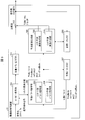
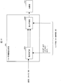
- FIG. 1 is a diagram showing a hierarchical structure of data in the encoded stream Te.
- the encoded stream Te illustratively includes a sequence and a plurality of pictures constituting the sequence.
- (A) to (f) of FIG. 1 respectively show a sequence layer that defines a sequence SEQ, a picture layer that defines a picture PICT, a slice layer that defines a slice S, a slice data layer that defines slice data, and a slice data.
- CU encoding unit
- Sequence layer In the sequence layer, a set of data referred to by the image decoding device 31 in order to decode a sequence SEQ to be processed (hereinafter also referred to as a target sequence) is defined.
- the sequence SEQ includes a video parameter set (Sequence Parameter Set), a picture parameter set PPS (Picture Parameter Set), a picture PICT, and an additional extension as shown in FIG.
- Information SEI Supplemental Enhancement Information
- # indicates the layer ID.
- FIG. 1 shows an example in which encoded data of # 0 and # 1, that is, layer 0 and layer 1, exists, the type of layer and the number of layers are not dependent on this.
- the video parameter set VPS is a set of encoding parameters common to a plurality of moving images, a plurality of layers included in the moving image, and encoding parameters related to individual layers in a moving image composed of a plurality of layers.
- a set is defined.
- the sequence parameter set SPS defines a set of encoding parameters that the image decoding device 31 refers to in order to decode the target sequence. For example, the width and height of the picture are defined. A plurality of SPSs may exist. In that case, one of a plurality of SPSs is selected from the PPS.
- a set of encoding parameters referred to by the image decoding device 31 in order to decode each picture in the target sequence is defined.
- a quantization width reference value (pic_init_qp_minus26) used for picture decoding and a flag (weighted_pred_flag) indicating application of weighted prediction are included.
- Picture layer In the picture layer, a set of data referred to by the image decoding device 31 for decoding a picture PICT to be processed (hereinafter also referred to as a target picture) is defined.
- the picture PICT includes slices S0 to SNS-1 as shown in FIG. 1B (NS is the total number of slices included in the picture PICT).
- slice layer In the slice layer, a set of data referred to by the image decoding device 31 for decoding the slice S to be processed (also referred to as a target slice) is defined. As shown in FIG. 1C, the slice S includes a slice header SH and slice data SDATA.
- the slice header SH includes an encoding parameter group that is referred to by the image decoding device 31 in order to determine a decoding method of the target slice.
- Slice type designation information (slice_type) for designating a slice type is an example of an encoding parameter included in the slice header SH.
- I slice using only intra prediction at the time of encoding (2) P slice using unidirectional prediction or intra prediction at the time of encoding, (3) B-slice using unidirectional prediction, bidirectional prediction, or intra prediction at the time of encoding may be used.
- the slice header SH may include a reference (pic_parameter_set_id) to the picture parameter set PPS included in the sequence layer.
- the slice data layer a set of data referred to by the image decoding device 31 for decoding the slice data SDATA to be processed is defined.
- the slice data SDATA includes a coded tree block (CTB) as shown in FIG.
- the CTB is a fixed-size block (for example, 64 ⁇ 64) constituting a slice, and may be called a maximum coding unit (LCU) and a coding tree unit (CTU).
- LCU maximum coding unit
- CTU coding tree unit
- the coding tree layer defines a set of data that the image decoding device 31 refers to in order to decode a coding tree block to be processed.
- the coding tree block is divided by recursive quadtree division.
- a tree-structured node obtained by recursive quadtree partitioning is called a coding tree.
- An intermediate node of the quadtree is a coded quadtree (CQT), and the coded tree block itself is also defined as the highest CQT.
- the CQT includes a split flag (split_flag). When the split_flag is 1, the CQT is split into four coding tree units CQT.
- the coding tree unit CQT is not divided and has one coding unit (CU: Coded Unit) as a node.
- the coding unit CU is a terminal node of the coding tree layer and is not further divided in this layer.
- the encoding unit CU is a basic unit of the encoding process.
- the size of the encoding unit is any of 64 ⁇ 64 pixels, 32 ⁇ 32 pixels, 16 ⁇ 16 pixels, and 8 ⁇ 8 pixels. It can take.
- the encoding unit layer defines a set of data referred to by the image decoding device 31 in order to decode the processing target encoding unit.
- the encoding unit includes an encoding tree, a prediction tree, a conversion tree, and a CU header CUF.
- a division flag, a division pattern, a prediction mode, and the like are defined.
- the prediction tree defines prediction information (reference picture index, motion vector, etc.) of each prediction block obtained by dividing the coding unit into one or a plurality.
- the prediction block is one or a plurality of non-overlapping areas constituting the coding unit.
- the prediction tree includes one or a plurality of prediction blocks obtained by the above division.
- a prediction unit obtained by further dividing the prediction block is referred to as a “sub-block”.
- a sub-block (prediction block) is composed of one or a plurality of pixels. When the sizes of the prediction block and the sub block are equal, the number of sub blocks in the prediction block is one. If the prediction block is larger than the size of the sub-block, the prediction block is divided into sub-blocks. For example, when the prediction block is 8 ⁇ 8 and the sub-block is 4 ⁇ 4, the prediction block is horizontally divided into two and vertically divided into two, and is divided into four sub-blocks.
- Prediction processing is performed for each prediction block (sub-block).
- a prediction block which is a unit of prediction is also referred to as a prediction unit (PU, prediction unit).
- Intra prediction is prediction within the same picture
- inter prediction refers to prediction processing performed between different pictures (for example, between display times and between layer images).
- the division method is encoded by the PU division mode (part_mode) of the encoded data.
- the division includes 2N ⁇ 2N (the same size as the encoding unit), 2N ⁇ N, 2N ⁇ nU, 2N ⁇ nD, N ⁇ 2N, nL ⁇ 2N, nR ⁇ 2N, and N ⁇ N.
- 2N ⁇ nU indicates that a 2N ⁇ 2N encoding unit is divided into two regions of 2N ⁇ 0.5N and 2N ⁇ 1.5N in order from the top.
- 2N ⁇ nD indicates that a 2N ⁇ 2N encoding unit is divided into two regions of 2N ⁇ 1.5N and 2N ⁇ 0.5N in order from the top.
- nL ⁇ 2N indicates that a 2N ⁇ 2N encoding unit is divided into two regions of 0.5N ⁇ 2N and 1.5N ⁇ 2N in order from the left.
- nR ⁇ 2N indicates that a 2N ⁇ 2N encoding unit is divided into two regions of 1.5N ⁇ 2N and 0.5N ⁇ 1.5N in order from the left. Since the number of divisions is one of 1, 2, and 4, the number of PUs included in the CU is 1 to 4. These PUs are expressed in order as PU0, PU1, PU2, and PU3.
- FIG. 2 specifically show the positions of the PU partition boundaries in the CU for each partition type.
- FIG. 2A shows a 2N ⁇ 2N PU partitioning mode in which CU partitioning is not performed.
- 2B, 2C, and 2D show the partition shapes when the PU partition modes are 2N ⁇ N, 2N ⁇ nU, and 2N ⁇ nD, respectively. ing.
- partitions when the PU partition mode is 2N ⁇ N, 2N ⁇ nU, and 2N ⁇ nD are collectively referred to as a horizontally long partition.
- FIG. 2 show the shapes of partitions when the PU partition modes are N ⁇ 2N, nL ⁇ 2N, and nR ⁇ 2N, respectively.
- partitions when the PU partition type is N ⁇ 2N, nL ⁇ 2N, and nR ⁇ 2N are collectively referred to as a vertically long partition.
- the horizontally long partition and the vertically long partition are collectively referred to as a rectangular partition.
- FIG. 2 shows the shape of the partition when the PU partition mode is N ⁇ N.
- the PU partitioning modes shown in FIGS. 2A and 2H are also referred to as square partitioning based on the shape of the partition.
- the PU division modes in FIGS. 2B to 2G are also referred to as non-square divisions.
- the numbers given to the respective regions indicate the identification numbers of the regions, and the processing is performed on the regions in the order of the identification numbers. That is, the identification number represents the scan order of the partitions.
- FIGS. 2A to 2H the upper left is the CU reference point (origin).
- the encoding unit is divided into one or a plurality of transform blocks, and the position and size of each transform block are defined.
- the transform block is one or a plurality of non-overlapping areas constituting the encoding unit.
- the conversion tree includes one or a plurality of conversion blocks obtained by the above division.
- the division in the transformation tree includes the one in which an area having the same size as that of the encoding unit is assigned as the transformation block, and the one in the recursive quadtree division like the above-described division in the tree block.
- a transform block that is a unit of transformation is also referred to as a transform unit (TU).
- the prediction image of the prediction unit is derived by a prediction parameter associated with the prediction unit.
- the prediction parameters include a prediction parameter for intra prediction or a prediction parameter for inter prediction.
- prediction parameters for inter prediction inter prediction (inter prediction parameters) will be described.
- the inter prediction parameter includes prediction list use flags predFlagL0 and predFlagL1, reference picture indexes refIdxL0 and refIdxL1, and vectors mvL0 and mvL1.
- the prediction list use flags predFlagL0 and predFlagL1 are flags indicating whether or not reference picture lists called L0 list and L1 list are used, respectively, and a reference picture list corresponding to a value of 1 is used.
- the prediction list use flag information can also be expressed by an inter prediction flag inter_pred_idc described later.
- a prediction list use flag is used in a prediction image generation unit (prediction image generation device) 308 and a prediction parameter memory 307 described later.
- an inter prediction flag inter_pred_idc is used when decoding information about which reference picture list is used from encoded data.
- Syntax elements for deriving inter prediction parameters included in the encoded data include, for example, a partition mode part_mode, a merge flag merge_flag, a merge index merge_idx, an inter prediction flag inter_pred_idc, a reference picture index refIdxLX, a prediction vector index mvp_LX_idx, and a difference There is a vector mvdLX.
- FIG. 3 is a conceptual diagram illustrating an example of a reference picture list.
- the reference picture list 601 five rectangles arranged in a line on the left and right indicate reference pictures, respectively.
- the codes P1, P2, Q0, P3, and P4 shown in order from the left end to the right are codes indicating respective reference pictures.
- P such as P1 indicates the viewpoint P
- Q of Q0 indicates a viewpoint Q different from the viewpoint P.
- the subscripts P and Q indicate the picture order number POC.
- a downward arrow directly below refIdxLX indicates that the reference picture index refIdxLX is an index that refers to the reference picture Q0 in the reference picture memory 306.
- FIG. 4 is a conceptual diagram illustrating an example of a reference picture.
- the horizontal axis indicates the display time
- the vertical axis indicates the viewpoint.
- the rectangles shown in FIG. 4 with 2 rows and 3 columns (6 in total) indicate pictures.
- the rectangle in the second column from the left in the lower row indicates a picture to be decoded (target picture), and the remaining five rectangles indicate reference pictures.
- a reference picture Q0 indicated by an upward arrow from the target picture is a picture that has the same display time as the target picture and a different viewpoint. In the displacement prediction based on the target picture, the reference picture Q0 is used.
- a reference picture P1 indicated by a left-pointing arrow from the target picture is a past picture at the same viewpoint as the target picture.
- a reference picture P2 indicated by a right-pointing arrow from the target picture is a future picture at the same viewpoint as the target picture. In motion prediction based on the target picture, the reference picture P1 or P2 is used.
- Inter prediction flag and prediction list usage flag The relationship between the inter prediction flag and the prediction list use flags predFlagL0 and predFlagL1 can be mutually converted as follows. Therefore, as an inter prediction parameter, a prediction list use flag may be used, or an inter prediction flag may be used. Hereinafter, the determination using the prediction list use flag may be replaced with the inter prediction flag. Conversely, the determination using the inter prediction flag may be replaced with a prediction list use flag.
- >> is a right shift
- ⁇ is a left shift.
- the prediction parameter decoding (encoding) method includes a merge prediction (merge) mode and an AMVP (Adaptive Motion Vector Prediction) mode.
- the merge flag merge_flag is a flag for identifying these.
- the prediction parameter of the target PU is derived using the prediction parameter of the already processed block.
- the merge prediction mode is a mode in which the prediction parameters of the neighboring PUs already derived are used as they are without including the prediction list use flag predFlagLX (or the inter prediction flag inter_pred_idc), the reference picture index refIdxLX, and the motion vector mvLX in the encoded data.
- the AMVP mode is a mode in which the inter prediction flag inter_pred_idc, the reference picture index refIdxLX, and the motion vector mvLX are included in the encoded data.
- the motion vector mvLX is encoded as a prediction vector index mvp_LX_idx for identifying the prediction vector mvpLX and a difference vector mvdLX.
- the inter prediction flag inter_pred_idc is data indicating the type and number of reference pictures, and takes any value of Pred_L0, Pred_L1, and Pred_Bi.
- Pred_L0 and Pred_L1 indicate that reference pictures stored in reference picture lists called an L0 list and an L1 list are used, respectively, and that both use one reference picture (single prediction). Prediction using the L0 list and the L1 list are referred to as L0 prediction and L1 prediction, respectively.
- Pred_Bi indicates that two reference pictures are used (bi-prediction), and indicates that two reference pictures stored in the L0 list and the L1 list are used.
- the prediction vector index mvp_LX_idx is an index indicating a prediction vector
- the reference picture index refIdxLX is an index indicating a reference picture stored in the reference picture list.
- LX is a description method used when L0 prediction and L1 prediction are not distinguished.
- refIdxL0 is a reference picture index used for L0 prediction
- refIdxL1 is a reference picture index used for L1 prediction
- refIdx (refIdxLX) is a notation used when refIdxL0 and refIdxL1 are not distinguished.
- the merge index merge_idx is an index indicating which one of the prediction parameter candidates (merge candidates) derived from the processed block is used as the prediction parameter of the decoding target block.
- target block may be a prediction block that is one level higher than a plurality of prediction blocks, or may be an encoding unit including the plurality of prediction blocks.
- the motion vector mvLX includes a displacement vector (disparity vector, indicating a shift amount between two blocks at the same time as a motion vector in a narrow sense (motion vector in a narrow sense) indicating a shift amount between blocks on two pictures at different times. (Parallax vector).
- the motion vector and the displacement vector are not distinguished, and are simply referred to as a motion vector mvLX.
- a prediction vector and a difference vector related to the motion vector mvLX are referred to as a prediction vector mvpLX and a difference vector mvdLX, respectively. Whether the motion vector mvLX and the difference vector mvdLX are motion vectors or displacement vectors is identified using a reference picture index refIdxLX attached to the vectors.
- FIG. 5 is a schematic diagram illustrating a configuration of the image decoding device 31 according to the present embodiment.
- the image decoding device 31 includes an entropy decoding unit 301, a prediction parameter decoding unit (prediction image generation device) 302, a reference picture memory (reference image storage unit, frame memory) 306, and a prediction parameter memory (prediction parameter storage unit, frame memory) 307.
- the prediction parameter decoding unit 302 includes an inter prediction parameter decoding unit (motion vector derivation unit) 303 and an intra prediction parameter decoding unit 304.
- the predicted image generation unit 308 includes an inter predicted image generation unit 309 and an intra predicted image generation unit 310.
- the entropy decoding unit 301 performs entropy decoding on the encoded stream Te input from the outside, and separates and decodes individual codes (syntax elements).
- the separated codes include prediction information for generating a prediction image and residual information for generating a difference image.
- the entropy decoding unit 301 outputs a part of the separated code to the prediction parameter decoding unit 302.
- Some of the separated codes are, for example, a prediction mode PredMode, a partition mode part_mode, a merge flag merge_flag, a merge index merge_idx, an inter prediction flag inter_pred_idc, a reference picture index refIdxLX, a prediction vector index mvp_LX_idx, and a difference vector mvdLX.
- Control of which code to decode is performed based on an instruction from the prediction parameter decoding unit 302.
- the entropy decoding unit 301 outputs the quantization coefficient to the inverse quantization / inverse DCT unit 311.
- the quantization coefficient is a coefficient obtained by performing quantization by performing DCT (Discrete Cosine Transform) on the residual signal in the encoding process.
- the inter prediction parameter decoding unit 303 decodes the inter prediction parameter with reference to the prediction parameter stored in the prediction parameter memory 307 based on the code input from the entropy decoding unit 301.
- the inter prediction parameter decoding unit 303 outputs the decoded inter prediction parameter to the prediction image generation unit 308 and stores it in the prediction parameter memory 307. Details of the inter prediction parameter decoding unit 303 will be described later.
- the intra prediction parameter decoding unit 304 refers to the prediction parameter stored in the prediction parameter memory 307 on the basis of the code input from the entropy decoding unit 301 and decodes the intra prediction parameter.
- the intra prediction parameter is a parameter used in a process of predicting a picture block within one picture, for example, an intra prediction mode IntraPredMode.
- the intra prediction parameter decoding unit 304 outputs the decoded intra prediction parameter to the prediction image generation unit 308 and stores it in the prediction parameter memory 307.
- the intra prediction parameter decoding unit 304 may derive different intra prediction modes depending on luminance and color difference.
- the intra prediction parameter decoding unit 304 decodes the luminance prediction mode IntraPredModeY as the luminance prediction parameter and the color difference prediction mode IntraPredModeC as the color difference prediction parameter.
- the luminance prediction mode IntraPredModeY is a 35 mode, and corresponds to planar prediction (0), DC prediction (1), and direction prediction (2 to 34).
- the color difference prediction mode IntraPredModeC uses one of the planar prediction (0), the DC prediction (1), the direction prediction (2 to 34), and the LM mode (35).
- the intra prediction parameter decoding unit 304 decodes a flag indicating whether IntraPredModeC is the same mode as the luminance mode, and assigns IntraPredModeY to IntraPredModeC if it indicates that the flag is the same mode as the luminance mode. If the flag indicates that the mode is different from the luminance mode, the intra prediction parameter decoding unit 304 uses IntraPredModeC as planar prediction (0), DC prediction (1), direction prediction (2 to 34), and LM mode (35 ) May be decrypted.
- the reference picture memory 306 stores the reference picture block (reference picture block) generated by the adding unit 312 at a predetermined position for each picture and block to be decoded.
- the prediction parameter memory 307 stores the prediction parameter in a predetermined position for each decoding target picture and block. Specifically, the prediction parameter memory 307 stores the inter prediction parameter decoded by the inter prediction parameter decoding unit 303, the intra prediction parameter decoded by the intra prediction parameter decoding unit 304, and the prediction mode predMode separated by the entropy decoding unit 301. .
- the stored inter prediction parameters include, for example, a prediction list use flag predFlagLX (inter prediction flag inter_pred_idc), a reference picture index refIdxLX, and a motion vector mvLX.
- the prediction image generation unit 308 receives the prediction mode predMode input from the entropy decoding unit 301 and the prediction parameter from the prediction parameter decoding unit 302. Further, the predicted image generation unit 308 reads a reference picture from the reference picture memory 306. The predicted image generation unit 308 generates a predicted picture block P (predicted image) using the input prediction parameter and the read reference picture in the prediction mode indicated by the prediction mode predMode.
- the inter prediction image generation unit 309 uses the inter prediction parameter input from the inter prediction parameter decoding unit 303 and the read reference picture to perform a prediction picture block by inter prediction. P is generated.
- the prediction picture block P corresponds to the prediction unit PU.
- the PU corresponds to a part of a picture composed of a plurality of pixels as a unit for performing the prediction process as described above, that is, a decoding target block on which the prediction process is performed at a time.
- the inter predicted image generation unit 309 uses the decoding target block as a reference from the reference picture indicated by the reference picture index refIdxLX.
- the reference picture block at the position indicated by mvLX is read from the reference picture memory 306.
- the inter prediction image generation unit 309 performs prediction on the read reference picture block to generate a prediction picture block P.
- the inter prediction image generation unit 309 outputs the generated prediction picture block P to the addition unit 312.
- the intra predicted image generation unit 310 When the prediction mode predMode indicates the intra prediction mode, the intra predicted image generation unit 310 performs intra prediction using the intra prediction parameter input from the intra prediction parameter decoding unit 304 and the read reference picture. Specifically, the intra predicted image generation unit 310 reads, from the reference picture memory 306, a reference picture block that is a decoding target picture and is in a predetermined range from the decoding target block among blocks that have already been decoded.
- the predetermined range is, for example, any of the left, upper left, upper, and upper right adjacent blocks when the decoding target block sequentially moves in a so-called raster scan order, and varies depending on the intra prediction mode.
- the raster scan order is an order in which each row is sequentially moved from the left end to the right end in each picture from the upper end to the lower end.
- the intra-predicted image generation unit 310 generates a predicted picture block by performing prediction in the prediction mode indicated by the intra-prediction mode IntraPredMode for the read reference picture block.
- the intra predicted image generation unit 310 outputs the generated predicted picture block P to the addition unit 312.
- the intra prediction image generation unit 310 When the intra prediction parameter decoding unit 304 derives different intra prediction modes for luminance and color difference, the intra prediction image generation unit 310 performs planar prediction (0), DC prediction (1), and so on according to the luminance prediction mode IntraPredModeY. A luminance prediction picture block is generated by any of the direction predictions (2 to 34). Further, the intra predicted image generation unit 310 predicts the color difference by any one of the planar prediction (0), the DC prediction (1), the direction prediction (2 to 344), and the LM mode (35) according to the color difference prediction mode IntraPredModeC. Generate a picture block.
- the inverse quantization / inverse DCT unit 311 inversely quantizes the quantization coefficient input from the entropy decoding unit 301 to obtain a DCT coefficient.
- the inverse quantization / inverse DCT unit 311 performs inverse DCT (Inverse Discrete Cosine Transform) on the obtained DCT coefficient to calculate a decoded residual signal.
- the inverse quantization / inverse DCT unit 311 outputs the calculated decoded residual signal to the addition unit 312 and the residual storage unit 313.
- the adder 312 outputs, for each pixel, the prediction picture block P input from the inter predicted image generator 309 and the intra predicted image generator 310 and the signal value of the decoded residual signal input from the inverse quantization / inverse DCT unit 311. Addition to generate a reference picture block.
- the adder 312 stores the generated reference picture block in the reference picture memory 306, and outputs a decoded layer image Td in which the generated reference picture block is integrated for each picture to the outside.
- FIG. 6 is a schematic diagram illustrating a configuration of the inter prediction parameter decoding unit 303 according to the present embodiment.
- the inter prediction parameter decoding unit 303 includes an inter prediction parameter decoding control unit (motion vector deriving unit) 3031, an AMVP prediction parameter deriving unit 3032, an adding unit 3035, and a merge prediction parameter deriving unit 3036.
- the inter prediction parameter decoding control unit 3031 instructs the entropy decoding unit 301 to decode a code (syntax element) related to inter prediction, and a code (syntax element) included in the encoded data, for example, a division mode part_mode, Merge flag merge_flag, merge index merge_idx, inter prediction flag inter_pred_idc, reference picture index refIdxLX, prediction vector index mvp_LX_idx, and difference vector mvdLX are extracted.
- the inter prediction parameter decoding control unit 3031 first extracts a merge flag.
- the inter prediction parameter decoding control unit 3031 expresses that a certain syntax element is to be extracted, it means that the entropy decoding unit 301 is instructed to decode a certain syntax element, and the corresponding syntax element is read from the encoded data. To do.
- the inter prediction parameter decoding control unit 3031 extracts the merge index merge_idx as a prediction parameter related to merge prediction.
- the inter prediction parameter decoding control unit 3031 outputs the extracted merge index merge_idx to the merge prediction parameter derivation unit 3036.
- the inter prediction parameter decoding control unit 3031 uses the entropy decoding unit 301 to extract the AMVP prediction parameter from the encoded data.
- AMVP prediction parameters include an inter prediction flag inter_pred_idc, a reference picture index refIdxLX, a prediction vector index mvp_LX_idx, and a difference vector mvdLX.
- the inter prediction parameter decoding control unit 3031 outputs the prediction list use flag predFlagLX derived from the extracted inter prediction flag inter_pred_idc and the reference picture index refIdxLX to the AMVP prediction parameter derivation unit 3032 and the prediction image generation unit 308 (FIG. 5).
- the inter prediction parameter decoding control unit 3031 outputs the extracted prediction vector index mvp_LX_idx to the AMVP prediction parameter derivation unit 3032.
- the inter prediction parameter decoding control unit 3031 outputs the extracted difference vector mvdLX to the addition unit 3035.
- FIG. 7 is a schematic diagram illustrating the configuration of the merge prediction parameter deriving unit 3036 according to the present embodiment.
- the merge prediction parameter derivation unit 3036 includes a merge candidate derivation unit 30361 (prediction vector calculation unit) and a merge candidate selection unit 30362.
- the merge candidate storage unit 303611 stores the merge candidates input from the merge candidate derivation unit 30361.
- the merge candidate includes a prediction list use flag predFlagLX, a motion vector mvLX, and a reference picture index refIdxLX.
- an index is assigned to the stored merge candidates according to a predetermined rule.
- the merge candidate derivation unit 30361 derives a merge candidate using the motion vector of the adjacent block that has already been decoded and the reference picture index refIdxLX as they are.
- merge candidates may be derived using affine prediction. This method is described in detail below.
- the merge candidate derivation unit 30361 may use affine prediction for a spatial merge candidate derivation process, a temporal merge (inter-frame merge) candidate derivation process, a merge merge candidate derivation process, and a zero merge candidate derivation process described later.
- Affine prediction is performed in units of sub-blocks, and prediction parameters are stored in the prediction parameter memory 307 for each sub-block.
- the affine prediction may be performed on a pixel basis.
- the merge candidate derivation unit 30361 reads and reads the prediction parameters (prediction list use flag predFlagLX, motion vector mvLX, reference picture index refIdxLX) stored in the prediction parameter memory 307 according to a predetermined rule.
- the predicted parameters are derived as merge candidates.
- the prediction parameter to be read is a prediction parameter related to each of the blocks within a predetermined range from the decoding target block (for example, all or a part of the blocks in contact with the lower left end, the upper left upper end, and the upper right end of the decoding target block). is there.
- the merge candidates derived by the merge candidate deriving unit 30361 are stored in the merge candidate storage unit 303611.
- the merge candidate derivation unit 30361 reads the prediction parameter of the block in the reference image including the lower right coordinate of the decoding target block from the prediction parameter memory 307 and sets it as a merge candidate.
- the reference picture designation method may be, for example, the reference picture index refIdxLX designated in the slice header, or may be designated using the smallest reference picture index refIdxLX of the block adjacent to the decoding target block.
- the merge candidates derived by the merge candidate deriving unit 30361 are stored in the merge candidate storage unit 303611.
- the merge candidate derivation unit 30361 combines two different derived merge candidate vectors and reference picture indexes that have already been derived and stored in the merge candidate storage unit 303611 as L0 and L1 vectors, respectively. Thus, a merge merge candidate is derived.
- the merge candidates derived by the merge candidate deriving unit 30361 are stored in the merge candidate storage unit 303611.
- the merge candidate derivation unit 30361 derives a merge candidate in which the reference picture index refIdxLX is 0 and both the X component and the Y component of the motion vector mvLX are 0.
- the merge candidates derived by the merge candidate deriving unit 30361 are stored in the merge candidate storage unit 303611.
- the merge candidate selection unit 30362 selects a merge candidate assigned with an index corresponding to the merge index merge_idx input from the inter prediction parameter decoding control unit 3031 among the merge candidates stored in the merge candidate storage unit 303611. As an inter prediction parameter.
- the merge candidate selection unit 30362 stores the selected merge candidate in the prediction parameter memory 307 and outputs it to the prediction image generation unit 308 (FIG. 5).
- FIG. 8 is a schematic diagram showing the configuration of the AMVP prediction parameter derivation unit 3032 according to this embodiment.
- the AMVP prediction parameter derivation unit 3032 includes a vector candidate derivation unit 3033 (vector calculation unit) and a vector candidate selection unit 3034.
- the vector candidate derivation unit 3033 reads a vector (motion vector or displacement vector) stored in the prediction parameter memory 307 based on the reference picture index refIdx as a prediction vector mvpLX.
- the vector to be read is a vector related to each of the blocks within a predetermined range from the decoding target block (for example, all or a part of the blocks in contact with the lower left end, the upper left upper end, and the upper right end of the decoding target block, respectively).
- the vector candidate selection unit 3034 selects the vector candidate indicated by the prediction vector index mvp_LX_idx input from the inter prediction parameter decoding control unit 3031 among the vector candidates read by the vector candidate derivation unit 3033 as the prediction vector mvpLX.
- the vector candidate selection unit 3034 outputs the selected prediction vector mvpLX to the addition unit 3035.
- the vector candidate selection unit 3034 may be configured to perform a round process described later on the selected prediction vector mvpLX.
- the vector candidate storage unit 30331 stores the vector candidates input from the vector candidate derivation unit 3033.
- the vector candidate is configured to include the prediction vector mvpLX.
- the stored vector candidates are assigned indexes according to a predetermined rule.
- the vector candidate derivation unit 3033 derives a vector candidate using affine prediction.
- the vector candidate derivation unit 3033 may use the affine prediction for a space vector candidate derivation process, a time vector (interframe vector) candidate derivation process, a combined vector candidate derivation process, and a zero vector candidate derivation process, which will be described later.
- Affine prediction is performed in units of sub-blocks, and the prediction parameters are stored in the prediction parameter memory 307 for each sub-block. Alternatively, the affine prediction may be performed on a pixel basis.
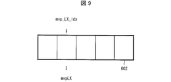
- FIG. 9 is a conceptual diagram showing an example of vector candidates.
- a predicted vector list 602 illustrated in FIG. 9 is a list including a plurality of vector candidates derived by the vector candidate deriving unit 3033.
- five rectangles arranged in a line on the left and right indicate areas indicating prediction vectors, respectively.
- the downward arrow directly below the second mvp_LX_idx from the left end and mvpLX below the mvp_LX_idx indicate that the prediction vector index mvp_LX_idx is an index that refers to the vector mvpLX in the prediction parameter memory 307.
- the vector candidate is generated based on the vector related to the block referred to by the vector candidate selection unit 3034.
- the block referred to by the vector candidate selection unit 3034 is a block for which decoding processing has been completed, and may be a block in a predetermined range from the decoding target block (for example, an adjacent block).
- the adjacent block is a block spatially adjacent to the decoding target block, for example, the left block, the upper block, or a block temporally adjacent to the decoding target block, for example, the same position as the decoding target block, at the display time. Includes blocks obtained from different blocks.
- the addition unit 3035 adds the prediction vector mvpLX input from the AMVP prediction parameter derivation unit 3032 and the difference vector mvdLX input from the inter prediction parameter decoding control unit 3031 to calculate a motion vector mvLX.
- the adding unit 3035 outputs the calculated motion vector mvLX to the predicted image generation unit 308 (FIG. 5).
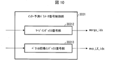
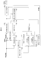
- FIG. 10 is a schematic diagram illustrating a configuration of the inter prediction parameter decoding control unit 3031 according to the present embodiment.
- the inter prediction parameter decoding control unit 3031 includes an additional prediction flag decoding unit 30311, a merge index decoding unit 30312, a vector candidate index decoding unit 30313, and a partition mode decoding unit, a merge flag decoding unit, an inter prediction flag decoding unit, not shown. It includes a picture index decoding unit, a vector difference decoding unit, and the like.
- the partition mode decoding unit, the merge flag decoding unit, the merge index decoding unit, the inter prediction flag decoding unit, the reference picture index decoding unit, the vector candidate index decoding unit 30313, and the vector difference decoding unit are respectively divided mode part_mode, merge flag merge_flag, merge The index merge_idx, inter prediction flag inter_pred_idc, reference picture index refIdxLX, prediction vector index mvp_LX_idx, and difference vector mvdLX are decoded.
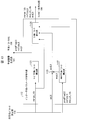
- FIG. 11 is a schematic diagram illustrating a configuration of the inter predicted image generation unit 309 according to the present embodiment.
- the inter prediction image generation unit 309 includes a motion compensation unit 3091 and a weight prediction unit 3094.
- the motion compensation unit 3091 Based on the prediction list use flag predFlagLX, the reference picture index refIdxLX, and the motion vector mvLX input from the inter prediction parameter decoding unit 303, the motion compensation unit 3091 refers to the reference specified by the reference picture index refIdxLX from the reference picture memory 306.
- a motion compensated image is generated by reading out a block at a position shifted by the motion vector mvLX, starting from the position of the decoding target block of the picture.
- a motion compensation image is generated by applying a filter for generating a pixel at a decimal position called a motion compensation filter.
- predSamplesL0 the motion compensation image for L0 prediction
- predSamplesL1 the motion compensation image for L1 prediction
- predSamplesLX the motion compensation image for L1 prediction
- the weight prediction unit 3094 generates a prediction picture block P (prediction image) by multiplying the input motion displacement image predSamplesLX by a weight coefficient.
- the input motion displacement images predSamplesLX are images on which residual prediction is performed when residual prediction is performed.
- the input motion displacement image predSamplesLX (LX is L0 or L1) is set to the number of pixel bits. The following formula is processed.
- predSamples [x] [y] Clip3 (0, (1 ⁇ bitDepth)-1, (predSamplesLX [x] [y] + offset1) >> shift1)
- shift1 14-bitDepth
- offset1 1 ⁇ (shift1-1).
- predFlagL0 or predFlagL1 are 1 (in the case of bi-prediction) and weight prediction is not used
- the input motion displacement images predSamplesL0 and predSamplesL1 are averaged to obtain the number of pixel bits.
- the following formula is processed.
- predSamples [x] [y] Clip3 (0, (1 ⁇ bitDepth)-1, (predSamplesL0 [x] [y] + predSamplesL1 [x] [y] + offset2) >> shift2)
- shift2 15-bitDepth
- offset2 1 ⁇ (shift2-1).
- the weight prediction unit 3094 when performing weight prediction, derives the weight prediction coefficient w0 and the offset o0 from the encoded data, and performs the processing of the following equation.
- predSamples [x] [y] Clip3 (0, (1 ⁇ bitDepth)-1, ((predSamplesLX [x] [y] * w0 + 2log2WD-1) >> log2WD) + o0)
- log2WD is a variable indicating a predetermined shift amount.
- the weight prediction unit 3094 when performing weight prediction, derives the heavy weight prediction coefficients w0, w1, o0, o1 from the encoded data, and performs the processing of the following equation.
- predSamples [x] [y] Clip3 (0, (1 ⁇ bitDepth)-1, (predSamplesL0 [x] [y] * w0 + predSamplesL1 [x] [y] * w1 + ((o0 + o1 + 1) ⁇ log2WD)) >> (log2WD + 1)) ⁇ Motion vector decoding process>
- predSamplesL0 [x] [y] * w0 + predSamplesL1 [x] [y] * w1 + ((o0 + o1 + 1) ⁇ log2WD)) >> (log2WD + 1))
- the motion vector decoding process includes a process of decoding syntax elements related to inter prediction (also referred to as motion syntax decoding process) and a process of deriving a motion vector ( Motion vector derivation process).
- FIG. 15 is a flowchart illustrating a flow of inter prediction syntax decoding processing performed by the inter prediction parameter decoding control unit 3031. In the following description in the description of FIG. 15, each process is performed by the inter prediction parameter decoding control unit 3031 unless otherwise specified.
- merge_flag! 0 is true (Y in S102)
- merge index merge_idx is decoded in S103, and the process proceeds to the motion vector derivation process (S201) in merge mode (FIG. 18A).
- inter prediction flag inter_pred_idc is decoded in S104
- the reference picture index refIdxL0 is decoded in S105
- the syntax mvdL0 of the difference vector is decoded in S106
- S107 The prediction vector index mvp_L0_idx is decoded.
- the reference picture index refIdxL1 is decoded.
- the difference vector syntax mvdL1 is decoded.
- the prediction vector index mvp_L1_idx is decoded.
- inter prediction flag inter_pred_idc is 0, that is, indicates L0 prediction (PRED_L0), the processing of S108 to S110 is not necessary.
- the inter prediction flag inter_pred_idc is 1, that is, indicates L1 prediction (PRED_L1), the processing of S105 to S107 is unnecessary.
- the inter prediction flag inter_pred_idc is 2, that is, indicates bi-prediction (PRED_B), steps S105 to S110 are executed.
- FIG. 16 is a flowchart showing more specifically the difference vector decoding process in steps S106 and S109 described above. So far, the horizontal and vertical components of the motion vector and the difference vector mvdLX have not been distinguished from each other, and are expressed as mvLX and mvdLX. Here, in order to clarify that the syntax of the horizontal component and the vertical component is required and that the processing of the horizontal component and the vertical component is necessary, using [0] and [1], Each component is indicated.
- step S10611 the syntax mvdAbsVal [0] indicating the horizontal motion vector difference absolute value is decoded from the encoded data.
- step S10615 the syntax mvdAbsVal [1] indicating the absolute value of the vertical motion vector difference is decoded.
- each of the motion vector difference absolute value mvdAbsVal and the motion vector difference code mvd_sign_flag is represented by a vector consisting of ⁇ horizontal component, vertical component ⁇ , the horizontal component is accessed with [0], and the vertical component is accessed with [1]. Yes.
- the vertical component may be [0] and the horizontal component may be [1].
- the vertical component is processed next to the horizontal component, but the processing order is not limited to this.
- the vertical component may be processed first and the horizontal component processed later (the same applies hereinafter).
- FIG. 17 is a flowchart illustrating an example in which the difference vector is decoded in steps S106 and S109 by a method different from the process illustrated in FIG.
- the steps already described in FIG. 16 are denoted by the same reference numerals in FIG.
- FIG. 17 differs from FIG. 16 in that the motion vector accuracy flag mvd_dequant_flag is further decoded.
- nonZeroMV 0? Is judged.
- variable nonZeroMV can be derived as follows.
- the motion vector accuracy flag mvd_dequant_flag is used to switch the accuracy of the motion vector. Further, when the flag is a flag for selecting whether or not the motion vector accuracy is full pel, it may be written as integer_mv_flag (may be described).
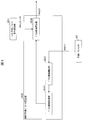
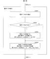
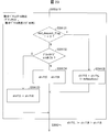
- FIG. 18 is a flowchart showing the flow of motion vector derivation processing performed by the inter prediction parameter decoding unit 303 according to this embodiment.
- FIG. 18A is a flowchart showing the flow of motion vector derivation processing in the merge prediction mode.
- the merge candidate derivation unit 30361 derives a merge candidate list mergeCandList.
- a differential motion vector mvdLX is derived from the decoded syntaxes mvdAbsVal and mv_sign_flag, and the motion vector mvLX is derived by adding the differential motion vector mvdLX to the prediction vector mvpLX.
- mvdAbsVal [0], mvdAbsVal [1], etc. and [0], [1] are used to distinguish the horizontal component from the vertical component. Without distinguishing components, it is simply described as mvdAbsVal. Actually, since the motion vector has a horizontal component and a vertical component, the processing described without distinguishing the components may be executed in order for each component.
- FIG. 18B is a flowchart showing the flow of motion vector derivation processing in the AMVP mode.
- the vector candidate deriving unit 3033 derives a motion vector predictor list mvpListLX.
- the inter prediction parameter decoding control unit 3031 derives a difference vector mvdLX.
- the vector candidate selection unit 3034 may round the selected prediction vector.
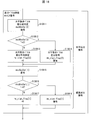
- FIG. 19 is a flowchart more specifically showing the difference vector deriving process in step S303 described above.
- the difference vector derivation process includes the following two processes. Inverse quantization process (PS_DQMV): A value decoded from encoded data, and the motion vector difference absolute value mvdAbsVal (quantized value), which is the quantized value, is inversely quantized to a specific accuracy (for example, described later) Processing to derive the motion vector difference absolute value mvdAbsVal (basic vector accuracy).
- Sign addition process PS_SIGN: A process for determining the sign of the derived motion vector difference absolute value mvdAbsVal and deriving the motion vector difference mvdLX.
- each process is performed by the inter prediction parameter decoding control unit 3031 unless otherwise specified.
- a motion vector scale shiftS which is a parameter for designating motion vector accuracy, is derived in S3031, and in S3032, it is determined whether or not motion vector scale> 0. If the motion vector scale> 0 is true, that is, shiftS> 0 (Y in S3032), in S3033, for example, the difference vector is inversely quantized by bit shift processing using shiftS.
- step S ⁇ b> 3034 a difference vector signing process is performed, and the process proceeds to step S ⁇ b> 3041.
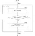
- FIG. 20 is a flowchart more specifically showing the prediction vector round process in step S304 described above.
- each process is performed by the vector candidate selection unit 3034 unless otherwise specified.
- a motion vector scale is derived in S3041, and a motion vector scale> 0 is determined in S3042. If the motion vector scale> 0 is true (Y in S3042), that is, if the difference vector is inversely quantized by the motion vector scale, the predicted motion vector mvpLX is rounded based on the motion vector scale in S3043.
- mvpLX round (mvpLX, shiftS) May be rounded (processing PS_PMVROUND).
- round (mvpLX, shiftS) represents a function that performs round processing using shiftS on the predicted motion vector mvpLX.
- the round process may use a formula (SHIFT-1) to (SHIFT-4), which will be described later, and the predicted motion vector mvpLX may be a value in 1 ⁇ shiftS units (separate value).
- a motion vector mvLX is derived from the prediction vector mvpLX and the difference vector mvdLX.
- the motion vector scale> 0 is false (N in S3042)
- the predicted motion vector mvpLX is not rounded but proceeds to S305, and the motion vector mvLX is derived.
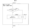
- FIG. 21 is a flowchart showing more specifically the motion vector scale derivation process in S3031 (see FIG. 19) and S3041 (see FIG. 20) described above.
- the process of S3041 is specifically illustrated for convenience of explanation, but the process shown in FIG. 21 may be applied to S3031.
- each process is performed by the inter prediction parameter decoding control unit 3031 unless otherwise specified.
- the value of mvBaseAccu is 2, for example. It progresses to S3042 after S304112.
- the accuracy of the motion vector is reduced when mvd_dequant_flag is 1, and the accuracy of the motion vector is maintained when mvd_dequant_flag is 0.
- the motion vector accuracy may be reduced, and 1 may maintain the motion vector accuracy. That is, for the flags shown in this specification, the numerical values and the contents indicated by the flags can be arbitrarily combined.
- the motion vector accuracy is switched with reference to the motion vector accuracy flag, so that a motion vector having more appropriate accuracy can be used.
- the amount of codes increases, and the encoding efficiency may not be improved as expected.
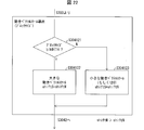
- FIG. 22 is a flowchart showing more specifically the motion vector scale derivation processing in S3031 (see FIG. 19) and S3041 (see FIG. 20) described above. In FIG. 22, for convenience of explanation, the process of S3041 is specifically illustrated, but the process shown in FIG. 22 may be applied to S3031.
- each process is performed by the inter prediction parameter decoding control unit 3031 unless otherwise specified.
- shiftS (blkW ⁇ TH)? shiftM: shiftN (Formula P1A)
- blkW + blkH ⁇ TH may be used instead of blkW ⁇ TH as a block size threshold value determination.
- the branch determination may use ⁇ (below) regardless of ⁇ (greater than), or may have an equivalent configuration in which the branches of Y and N are reversed as> and ⁇ . Note that the above-described changes may be applied as appropriate in other processes in this specification.
- the motion vector scale is derived so that the value of the motion vector scale is smaller (the motion vector accuracy is higher) as the block size is larger according to the block size.
- the number of block size classifications is not limited to 2, and may be 3 or more. .
- the accuracy of the difference vector can be switched according to the block size. For example, when the block size is larger than a predetermined value, it can be switched to a high-precision vector, and when the block size is smaller than a predetermined value, it can be switched to a low-precision motion vector.
- a motion vector with more appropriate accuracy can be used.
- the accuracy of the difference vector can be switched without using the motion vector accuracy flag. Therefore, it is not necessary to encode and decode the motion vector accuracy flag, and the code amount of the encoded data is reduced. This can also improve the encoding efficiency.
- FIG. 23 is a flowchart showing more specifically the motion vector scale derivation processing in S3031 and S3041 described above.
- the process of S3041 is specifically illustrated for convenience of explanation, but the process shown in FIG. 23 may be applied to S3031.
- the block size classification may be classified into three or more, regardless of the two classifications.
- the accuracy of the motion vector is determined with reference to both the block size and the motion vector accuracy flag, a motion vector having a more appropriate accuracy can be used.
- the motion vector accuracy flag indicates the accuracy of the motion vector in integer accuracy (low accuracy)
- the accuracy of the difference vector is set to integer accuracy (low accuracy) regardless of the block size.
- the motion vector accuracy flag indicates the accuracy of the motion vector with decimal accuracy (high accuracy)
- the accuracy of the difference vector can be further switched according to the block size.
- the inter prediction parameter decoding unit 303 (motion vector deriving unit) derives a motion vector by adding or subtracting a difference vector to or from a prediction vector for each prediction block.
- the inter prediction parameter decoding unit 303 switches the accuracy of the motion vector derived for the prediction block (particularly the shift value used for deriving the motion vector difference absolute value) according to the size of the prediction block.
- the motion vector derived by the above-described motion vector derivation processing can be expressed by the following equation.
- the inverse quantization of the difference vector mvdLX shown in the above section may be performed on the motion vector difference absolute value.
- the motion vector difference absolute value mvdAbsVal may be inversely quantized to perform a coding process.
- the variables mvdAbsVal and mvdLX are represented by a configuration that is updated. However, in order to clarify the processing, they can be represented as follows by using “′”.
- the absolute value of the difference motion vector before dequantization (quantized) may be represented by qmvd instead of mvdAbsVal.
- round processing In the above description, the round process is mentioned. A specific example of the round process does not limit the present embodiment.
- round (mvpLX) (mvpLX >> shiftS ⁇ shiftS) ... (SHIFT-1) May be used.
- the variable in round () is not limited to mvpLX.
- offset value offsetS 1 ⁇ (shiftS-1)
- round (mvpLX) ((mvpLX + offsetS) >> shiftS) ⁇ shiftS ... (SHIFT-2) It is good.
- round (mvpLX) mvpLX> 0?
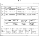
- FIG. 24A to 24C are tables showing the relationship between the basic vector accuracy and the parameter (shiftS) indicating the motion vector accuracy set (switched) by the block size of the target block.
- the inter prediction parameter decoding control unit 3031 may perform the above-described processing from S304121 to S304123 shown in FIG. 22 as in the examples shown in (a) to (c) of FIG.
- the concept of “basic vector” is introduced, and a parameter that specifies the accuracy of this basic vector is represented by mvBaseAccu.
- the “basic vector” is virtually decoded with the accuracy of 1 ⁇ mvBaseAccu.
- the name “basic vector” is merely for convenience, and “basic vector” is merely introduced as a reference for specifying the accuracy of the motion vector.
- FIG. 24 (a) is a table showing the relationship between the block size of the target block, the basic vector accuracy, and the parameter shiftS indicating the motion vector accuracy when the motion vector accuracy is switched between two values.
- mvBaseAccu 3
- the accuracy of the basic vector is 1/8 pel.
- shiftS 0
- the motion vector accuracy is 1/8 pel.
- FIG. 24B is a table showing the relationship between the block size of the target block, the basic vector accuracy, and the parameter (shiftS) indicating the motion vector accuracy when the motion vector accuracy is switched to three values.
- FIG. 24C is a table showing the relationship among the block size of the target block, the basic vector accuracy, and the parameter (shiftS) indicating the motion vector accuracy when the motion vector accuracy is switched to five values.
- the inter prediction parameter decoding control unit 3031 may be configured to perform inverse quantization by a product of the motion vector quantization step size MVQStep instead of the left shift by the motion vector scale shiftS. That is, inverse quantization may be performed by the following equation instead of the equation (Scale).
- MVQStep mvdAbsVal * MVQStep expression (QStep)
- the accuracy of the basic motion vector is 1/8
- the accuracy of the motion vector to be encoded is 1/8
- the quantization step MVQStep is 2, it is encoded.
- the accuracy of the motion vector (MVStep) is 1/4. Therefore, if the accuracy of the basic motion vector is 1 / mvBaseAccu, the accuracy MVStep of the motion vector to be encoded in the quantization step MVQStep is 1 / mvBaseAccu * MVQStep.
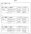
- FIG. 25 (Example of motion vector accuracy switched using block size and motion vector accuracy flag)
- mvd_dequant_flag a specific example of motion vector accuracy (derivation processing PS_P1B) that is switched using the block size and the motion vector accuracy flag mvd_dequant_flag
- FIGS. 25A to 25C an example in which the basic vector accuracy is 1/16 is shown, but any value can be applied as the value of the basic vector accuracy.
- the inter prediction parameter decoding control unit 3031 may perform the above-described processing from S304131 to S304135 shown in FIG. 23 as in the examples shown in (a) to (c) of FIG.
- shiftS 0 is set, and the motion vector accuracy MVStep is 1. / 16pel.
- shiftS 2 is set, and the motion vector accuracy is 1/4 pel.
- the inter prediction parameter decoding control unit 3031 may derive shiftS based on QP (Quantization Parameter) that is a quantization parameter instead of the block size of the target block (derivation).
- QP Quantization Parameter
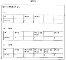
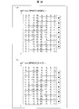
- FIG. 26A to 26C are tables showing parameters (shiftS) indicating motion vector accuracy set (switched) by QP.
- the inter prediction parameter decoding control unit 3031 may perform the difference vector derivation process as in the examples illustrated in (a) to (c) of FIG.
- the basic vector accuracy value is not particularly mentioned, but an arbitrary basic vector accuracy value can be used.
- 26 (a), (b), and (c) show examples in which two, three, and five values are switched according to QP, respectively, the number of switching (number of QP classifications) is not limited to this. .
- the threshold value used for QP classification is not limited to the example shown in the figure.
- FIG. 26 (a) is a table showing the relationship between QP and motion vector accuracy (shiftS) when the motion vector accuracy is switched between two values.
- shiftS motion vector accuracy
- 26B is a table showing the relationship between the QP and the parameter (shiftS) indicating the motion vector accuracy when the motion vector accuracy is switched to three values.
- shiftS the parameter
- FIG. 26C is a table showing the correspondence between the QP and the parameter (shiftS) indicating the motion vector accuracy when the motion vector accuracy is switched to five values.
- the accuracy of the motion vector derived with respect to the prediction block is switched according to the size of the quantization parameter, so that a prediction image can be generated using a motion vector having appropriate accuracy.
- the inter prediction parameter decoding control unit 3031 may be configured to derive MVQStep instead of the above-described shiftS as the motion vector accuracy according to the block size of the target block.
- FIGS. 27A and 27B are tables showing motion vector accuracy (shiftS) set (switched) by the QP and the motion vector accuracy flag.
- the inter prediction parameter decoding control unit 3031 may perform the difference vector derivation process as in the example illustrated in FIGS.
- the motion vector accuracy flag mvd_dequant_flag 1 (other than 0)
- FIG. 27B shows an example in which the motion vector scale shiftS is derived according to QP even when the motion vector accuracy flag is 1 (other than 0).
- the processing described below is performed by the inter prediction parameter decoding control unit 3031 unless otherwise specified.
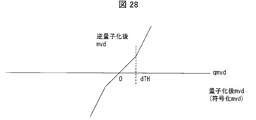
- the quantized difference vector is equivalent to the value mvdAbsVal of the difference vector absolute value at the time point obtained by decoding the syntax of the encoded data (the time point before inverse quantization), and the absolute value of qmvd is mvdAbsVal.
- the difference vector quantization value qmvd can be either positive or negative in order to clarify the image regardless of whether the difference vector is negative or positive.
- FIG. 28 is a graph showing the relationship between the quantized difference vector and the dequantized difference vector in this processing example.
- the horizontal axis of the graph shown in FIG. 28 is qmvd which is a quantized difference vector (decoded difference vector quantized and encoded by the encoding device and not dequantized, that is, ,
- the inter prediction parameter decoding control unit 3031 performs an inverse quantization process on the quantized difference vector qmvd as shown in the graph of FIG.
- the addition unit 3035 derives a motion vector by adding or subtracting the dequantized difference vector to the prediction vector.
- mvdLX mvdAbsVal * (1-2 * mv_sign_flag)
- mvLX round (mvpLX) + mvdLX Derived by
- the inter prediction parameter decoding control unit 3031 performs inverse quantization of the quantized motion vector according to the magnitude relationship between the quantized motion vector difference decoded from the encoded data and a predetermined value (dTH). Switch the accuracy of processing.
- the accuracy of the motion vector is set high, and when the absolute value of the difference vector mvd is large, the accuracy of the motion vector is set low.
- the quantized difference vector qmvd is changed compared to when the absolute value of the difference vector mvd is far from the vicinity of the zero point.
- the inverse quantization difference vector mvd changes small.
- the inter prediction parameter decoding control unit 3031 has a predetermined inclination with respect to the quantized difference vector qmvd.
- the predetermined inclination may be 1, for example.
- mvdAbsVal is the absolute value of the difference vector after inverse quantization
- K represents a predetermined proportional coefficient.
- the product by K may be realized by a left shift by log2 (K).
- the quantized difference vector qmvd is 16 or more (the motion vector accuracy is equivalent to 2 pel or more)
- the quantization difference vector qmvd is 16 or more (the motion vector accuracy is equivalent to 1 pel or more)
- the inter-prediction parameter decoding control unit 3031 performs inverse quantization specified by the gradient obtained by the above. If the quantized difference vector qmvd is greater than or equal to the threshold value dTH (or greater than dTH), 1 ⁇ shiftS2 The inter-prediction parameter decoding control unit 3031 performs inverse quantization specified by the gradient obtained by the above.
- shiftS1 and shiftS2 may or may not be equal to each other.
- the motion vector accuracy flag mvd_dequant_flag 0 is satisfied
- the predetermined threshold value qmvd 16 (equivalent to 1 pel) or more
- shiftS 2 bits
- a predicted image can be generated using a motion vector with more appropriate accuracy. For this reason, since prediction accuracy improves, encoding efficiency improves.
- the quantized value of the quantized difference vector indicates whether the accuracy of the inverse quantization process for the difference vector is the third accuracy or the fourth accuracy. Switch according to. At least one of the first accuracy and the second accuracy is higher than the third accuracy and the fourth accuracy.
- the inter prediction parameter decoding control unit 3031 sets the motion vector accuracy to the basic vector accuracy 1/8 Set to.
- a predicted image can be generated using a motion vector with more appropriate accuracy. For this reason, since prediction accuracy improves, encoding efficiency improves.
- the vector candidate selection unit 3034 performs round processing on the inversely quantized difference vector.
- a motion vector is derived by adding or subtracting to the prediction vector.
- the motion vector accuracy of mvpLX is reduced to the accuracy of 1 ⁇ shiftS units.
- the process of deriving mvdLX from mvdAbsVal is as described for the sign assignment process PS_SIGN.
- the inter prediction parameter decoding control unit 3031 converts the difference vector obtained by inverse quantization according to the motion vector accuracy flag and the quantized difference vector to the prediction vector subjected to the round processing by the vector candidate selection unit 3034.
- a motion vector is derived by addition or subtraction.
- mvdAbsVal qmvd ⁇ shiftA Derives mvdAbs.
- the motion vector accuracy of mvpLX is lowered to the accuracy of 1 ⁇ shiftA units.
- the process of deriving mvdLX from mvdAbsVal is as described for the sign assignment process PS_SIGN.
- the quantized difference vector qmvd is less than the predetermined value dTH
- the motion vector mvLX is the sum of the prediction vector mvpLX and the difference vector mvdLX.
- mvLX round (mvpLX, shiftS) + mvdLX Is derived by
- the motion vector accuracy of mvpLX is reduced to the accuracy of 1 ⁇ shiftS units.
- the process of deriving mvdLX from mvdAbsVal is as described for the sign assignment process PS_SIGN.
- the inter prediction parameter decoding control unit 3031 performs inverse operation on the difference vector with accuracy other than the highest accuracy among the first accuracy, the second accuracy, the third accuracy, and the fourth accuracy.
- the addition unit 3035 derives a motion vector by adding or subtracting the dequantized difference vector to the prediction vector subjected to the round process by the vector candidate selection unit 3034. .
- round (mvpLX, shiftA1) the motion vector accuracy of mvpLX is reduced to the accuracy of 1 ⁇ shiftA1 unit.
- mvd_dequant_flag 1
- mvdAbsVal predetermined value dTHA ⁇ shiftA1 + (qmvd-dTHA) ⁇ shiftA2 Yields mvdAbsVal.
- round (mvpLX, shiftA2) the motion vector accuracy of mvpLX is reduced to the accuracy of 1 ⁇ shiftA2.
- the process of deriving mvdLX from mvdAbsVal is as described for the sign assignment process PS_SIGN.
- the quantized difference vector qmvd is less than the predetermined value dTH
- the motion vector mvLX is the sum of the prediction vector mvpLX and the difference vector mvdLX.
- mvLX round (mvpLX, shiftS) + mvdLX Is derived by
- the motion vector accuracy of mvpLX is reduced to the accuracy of 1 ⁇ shiftS units.
- the process of deriving mvdLX from mvdAbsVal is as described for the sign assignment process PS_SIGN.
- FIG. 29 is a flowchart showing more specifically the motion vector scale derivation processing in S3031 (see FIG. 19) and S3041 (see FIG. 20) described above.
- the process of S3041 is specifically illustrated for convenience of explanation, but the process shown in FIG. 22 may be applied to S3031.
- FIG. 30 is a block diagram showing a specific configuration of the motion compensation unit 3091.
- the motion compensation unit 3091 includes a motion vector application unit 30911, a motion compensation filter unit (filter unit) 30912, and a filter coefficient memory 30913.
- the motion vector application unit 3091 is designated by the reference picture index refIdxLX from the reference picture memory 306 based on the prediction list use flag predFlagLX, the reference picture index refIdxLX, and the motion vector mvLX input from the inter prediction parameter decoding unit 303.
- a motion vector applied image is generated by reading a block at a position shifted by the motion vector mvLX, starting from the position of the decoding target block of the reference picture.
- the motion vector applied image also has 1 / M pixel accuracy.
- the motion compensation filter 30912 uses the filter coefficient mcFilter [i] [k] (where i is an integer between 0 and M-1, and k is an integer between 0 and Ntaps-1). Is applied to a motion vector-applied image to distinguish between the above-described motion compensated images (predSamplesL0 for a motion compensated image for L0 prediction and predSamplesL1 for a motion compensated image for L1 prediction). If not, generate predSamplesLX).
- the motion compensation filter 30912 does not act on the motion vector applied image, and the motion vector applied image becomes the motion compensated image as it is.
- the filter coefficient memory 30913 stores motion compensation filter coefficients decoded from the encoded data. More specifically, the filter coefficient memory 30913 is a filter coefficient mcFilter [i] [k] used by the motion compensation filter 30912 (where i is an integer from 0 to M ⁇ 1, and k is from 0 to Ntaps ⁇ 1). Among the following integers), at least some of the filter coefficients relating to i are stored.
- FIG. 31 is a diagram illustrating an example of filter coefficients according to the present embodiment.
- the accuracy of the motion vector is 1/16 pixel accuracy. That is, when the total number of phases is M, the accuracy of the motion vector is 1 / M pixel accuracy.
- the coefficient position means the relative position of the pixel on which the filter coefficient is applied.
- the total number of filter coefficients is a value obtained by multiplying the number of taps of the filter and the number of phases (that is, the reciprocal of the accuracy of the motion vector).
- the filter coefficient mcFilter [i] [k] used by the motion compensation filter unit (filter unit) 30912 includes a filter coefficient mcFilter [p] [k] (p ⁇ i) and a filter coefficient mcFilter [q] [k] (q The filter coefficient calculated using ⁇ i) may be included. Details of a calculation example of the filter coefficient mcFilter [i] [k] are as follows.
- the motion compensation filter unit 30912 calculates a filter coefficient of another phase (here, odd number) from a filter coefficient of a part (even number here) phase, and uses the calculated filter coefficient.
- a filter coefficient of another phase here, odd number
- even-phase filter coefficients are shown with an underline.
- the filter coefficient memory 30913 stores even-numbered phase filter coefficients.
- filter coefficients of odd-numbered phases may be stored in the filter coefficient memory 30913, and the stored filter coefficients may be used as the filter coefficients by the motion compensation filter unit 30912.
- the division described by / 2 may be >> 1.
- the following table may be used as mcFilterC.
- FIG. 32B shows an example in which the motion compensation filter unit 30912 calculates a filter coefficient of another phase (even phase) from a part (here, odd phase) of filter coefficients.
- the odd phase filter coefficients are shown with an underline.
- the filter coefficient memory 30913 stores odd-numbered phase filter coefficients.
- / 2 may be >> 1.
- the following table may be used as mcFilterC.
- mcFilterC [] ⁇ ⁇ 0, 0, 0, 64, 0, 0, 0, 0 ⁇ , ⁇ 0, 1, -3, 63, 4, -2, 1, 0 ⁇ , ⁇ -1, 3, -8, 60, 13, -4, 1, 0 ⁇ , ⁇ -1, 4, -11, 52, 26, -8, 3, -1 ⁇ , ⁇ -1, 4, -11, 45, 34, -10, 4, -1 ⁇ , ⁇ -1, 4, -10, 34, 45, -11, 4, -1 ⁇ , ⁇ -1, 3, -8, 26, 52, -11, 4, -1 ⁇ , ⁇ 0, 1, -4, 13, 60, -8, 3, -1 ⁇ , ⁇ 0, 1, -2, 4, 63, -3, 1, 0 ⁇ ⁇
- even partial filter coefficients of some phases may be stored in the filter coefficient memory 30913, and the motion compensation filter unit 30912 may use the stored filter coefficients as filter coefficients.
- mcFilter [i] [k] ((Nw) * mcFilter [i0] [k] + w * mcFilter [i1] [k]) >> log (N)
- i0 (i / N) * N
- i1 i0 + N
- w (i% N)
- N is an integer of 2 or more.
- the following structures may be sufficient.
- FIG. 12 is a block diagram illustrating a configuration of the image encoding device 11 according to the present embodiment.
- the image encoding device 11 includes a prediction image generation unit 101, a subtraction unit 102, a DCT / quantization unit 103, an entropy encoding unit 104, an inverse quantization / inverse DCT unit 105, an addition unit 106, a prediction parameter memory (prediction parameter storage) Unit, frame memory) 108, reference picture memory (reference image storage unit, frame memory) 109, coding parameter determination unit 110, prediction parameter coding unit 111, and residual storage unit 313 (residual recording unit). Is done.
- the prediction parameter encoding unit 111 includes an inter prediction parameter encoding unit 112 and an intra prediction parameter encoding unit 113.
- the predicted image generation unit 101 generates a predicted picture block P for each block which is an area obtained by dividing the picture for each viewpoint of the layer image T input from the outside.
- the predicted image generation unit 101 reads the reference picture block from the reference picture memory 109 based on the prediction parameter input from the prediction parameter encoding unit 111.
- the prediction parameter input from the prediction parameter encoding unit 111 is, for example, a motion vector or a displacement vector.
- the predicted image generation unit 101 reads the reference picture block of the block at the position indicated by the motion vector or the displacement vector predicted from the encoding target block.
- the prediction image generation unit 101 generates a prediction picture block P using one prediction method among a plurality of prediction methods for the read reference picture block.
- the predicted image generation unit 101 outputs the generated predicted picture block P to the subtraction unit 102. Note that since the predicted image generation unit 101 performs the same operation as the predicted image generation unit 308 already described, details of generation of the predicted picture block P are omitted.
- the predicted image generation unit 101 minimizes an error value based on a difference between a signal value for each pixel of a block included in an image and a signal value for each corresponding pixel of the predicted picture block P. Select the prediction method to use. The method for selecting the prediction method is not limited to this.
- the multiple prediction methods are intra prediction, motion prediction, and merge prediction.
- Motion prediction is prediction between display times among the above-mentioned inter predictions.
- the merge prediction is a prediction that uses the same reference picture block and prediction parameter as a block that has already been encoded and is within a predetermined range from the encoding target block.
- the prediction image generation unit 101 When the intra prediction is selected, the prediction image generation unit 101 outputs a prediction mode IntrapredMode indicating the intra prediction mode used when generating the prediction picture block P to the prediction parameter encoding unit 111.
- the predicted image generation unit 101 when selecting motion prediction, stores the motion vector mvLX used when generating the predicted picture block P in the prediction parameter memory 108 and outputs the motion vector mvLX to the inter prediction parameter encoding unit 112.
- the motion vector mvLX indicates a vector from the position of the encoding target block to the position of the reference picture block when the predicted picture block P is generated.
- the information indicating the motion vector mvLX may include information indicating a reference picture (for example, a reference picture index refIdxLX, a picture order number POC), and may represent a prediction parameter.
- the predicted image generation unit 101 outputs a prediction mode predMode indicating the inter prediction mode to the prediction parameter encoding unit 111.
- the prediction image generation unit 101 selects merge prediction
- the prediction image generation unit 101 outputs a merge index merge_idx indicating the selected reference picture block to the inter prediction parameter encoding unit 112. Further, the predicted image generation unit 101 outputs a prediction mode predMode indicating the merge prediction mode to the prediction parameter encoding unit 111.
- the predicted image generation unit 101 may have a configuration for generating a motion compensation filter coefficient referred to by the motion compensation unit 3091 provided in the image decoding device 31.
- the predicted image generation unit 101 may have a configuration corresponding to the motion vector accuracy switching described in the image decoding device 31. That is, the predicted image generation unit 101 may switch the accuracy of the motion vector according to the block size, QP, and the like.
- the image decoding device 31 may be configured to encode a motion vector accuracy flag mvd_dequant_flag that is referred to when the accuracy of the motion vector is switched.
- the subtraction unit 102 subtracts the signal value of the prediction picture block P input from the prediction image generation unit 101 for each pixel from the signal value of the corresponding block of the layer image T input from the outside, and generates a residual signal. Generate.
- the subtraction unit 102 outputs the generated residual signal to the DCT / quantization unit 103 and the encoding parameter determination unit 110.
- the DCT / quantization unit 103 performs DCT on the residual signal input from the subtraction unit 102 and calculates a DCT coefficient.
- the DCT / quantization unit 103 quantizes the calculated DCT coefficient to obtain a quantization coefficient.
- the DCT / quantization unit 103 outputs the obtained quantization coefficient to the entropy coding unit 104 and the inverse quantization / inverse DCT unit 105.
- the entropy encoding unit 104 receives a quantization coefficient from the DCT / quantization unit 103 and receives an encoding parameter from the encoding parameter determination unit 110.
- input encoding parameters include codes such as a reference picture index refIdxLX, a prediction vector index mvp_LX_idx, a difference vector mvdLX, a prediction mode predMode, and a merge index merge_idx.
- the entropy encoding unit 104 may be configured to perform a process corresponding to the nonlinear inverse quantization process described in the image decoding device 31, that is, a nonlinear quantization process for the difference vector, before encoding the difference vector mvdLX. Good.
- the entropy encoding unit 104 generates an encoded stream Te by entropy encoding the input quantization coefficient and encoding parameter, and outputs the generated encoded stream Te to the outside.
- the inverse quantization / inverse DCT unit 105 inversely quantizes the quantization coefficient input from the DCT / quantization unit 103 to obtain a DCT coefficient.
- the inverse quantization / inverse DCT unit 105 performs inverse DCT on the obtained DCT coefficient to calculate a decoded residual signal.
- the inverse quantization / inverse DCT unit 105 outputs the calculated decoded residual signal to the addition unit 106.
- the adding unit 106 adds the signal value of the predicted picture block P input from the predicted image generation unit 101 and the signal value of the decoded residual signal input from the inverse quantization / inverse DCT unit 105 for each pixel, and refers to Generate a picture block.
- the adding unit 106 stores the generated reference picture block in the reference picture memory 109.
- the prediction parameter memory 108 stores the prediction parameter generated by the prediction parameter encoding unit 111 at a predetermined position for each picture and block to be encoded.
- the reference picture memory 109 stores the reference picture block generated by the adding unit 106 at a predetermined position for each picture and block to be encoded.
- the encoding parameter determination unit 110 selects one set from among a plurality of sets of encoding parameters.
- the encoding parameter is a parameter to be encoded that is generated in association with the above-described prediction parameter or the prediction parameter.
- the predicted image generation unit 101 generates a predicted picture block P using each of these sets of encoding parameters.
- the encoding parameter determination unit 110 calculates a cost value indicating the amount of information and the encoding error for each of a plurality of sets.
- the cost value is, for example, the sum of a code amount and a square error multiplied by a coefficient ⁇ .
- the code amount is the information amount of the encoded stream Te obtained by entropy encoding the quantization error and the encoding parameter.
- the square error is the sum between pixels regarding the square value of the residual value of the residual signal calculated by the subtracting unit 102.
- the coefficient ⁇ is a real number larger than a preset zero.
- the encoding parameter determination unit 110 selects a set of encoding parameters that minimizes the calculated cost value. As a result, the entropy encoding unit 104 outputs the selected set of encoding parameters to the outside as the encoded stream Te, and does not output the set of unselected encoding parameters.
- the prediction parameter encoding unit 111 derives a prediction parameter used when generating a prediction picture based on the parameter input from the prediction image generation unit 101, and encodes the derived prediction parameter to generate a set of encoding parameters. To do.
- the prediction parameter encoding unit 111 outputs the generated set of encoding parameters to the entropy encoding unit 104.
- the prediction parameter encoding unit 111 stores, in the prediction parameter memory 108, a prediction parameter corresponding to the set of the generated encoding parameters selected by the encoding parameter determination unit 110.
- the prediction parameter encoding unit 111 operates the inter prediction parameter encoding unit 112 when the prediction mode predMode input from the prediction image generation unit 101 indicates the inter prediction mode.
- the prediction parameter encoding unit 111 operates the intra prediction parameter encoding unit 113 when the prediction mode predMode indicates the intra prediction mode.
- the inter prediction parameter encoding unit 112 derives an inter prediction parameter based on the prediction parameter input from the encoding parameter determination unit 110.
- the inter prediction parameter encoding unit 112 includes the same configuration as the configuration in which the inter prediction parameter decoding unit 303 (see FIG. 5 and the like) derives the inter prediction parameter as a configuration for deriving the inter prediction parameter.
- the configuration of the inter prediction parameter encoding unit 112 will be described later.
- the intra prediction parameter encoding unit 113 determines the intra prediction mode IntraPredMode indicated by the prediction mode predMode input from the encoding parameter determination unit 110 as a set of inter prediction parameters.
- the inter prediction parameter encoding unit 112 is means corresponding to the inter prediction parameter decoding unit 303.
- FIG. 13 is a schematic diagram illustrating a configuration of the inter prediction parameter encoding unit 112 according to the present embodiment.
- the inter prediction parameter encoding unit 112 includes a merge prediction parameter derivation unit 1121, an AMVP prediction parameter derivation unit 1122, a subtraction unit 1123, and a prediction parameter integration unit 1126.
- the merge prediction parameter derivation unit 1121 has the same configuration as the merge prediction parameter derivation unit 3036 (see FIG. 7) described above, and the AMVP prediction parameter derivation unit 1122 includes the AMVP prediction parameter derivation unit 3032 (see FIG. 8). It has the same configuration as.
- the merge index merge_idx is input from the encoding parameter determination unit 110 to the merge prediction parameter derivation unit 1121 when the prediction mode predMode input from the prediction image generation unit 101 indicates the merge prediction mode.
- the merge index merge_idx is output to the prediction parameter integration unit 1126.
- the merge prediction parameter derivation unit 1121 reads the reference picture index refIdxLX and the motion vector mvLX of the reference block indicated by the merge index merge_idx from the prediction candidates from the prediction parameter memory 108.
- a merge candidate is a reference block within a predetermined range from an encoding target block to be encoded (for example, a reference block in contact with the lower left end, upper left upper end, and upper right end of the encoding target block). This is a reference block that has been processed.
- the AMVP prediction parameter derivation unit 1122 has the same configuration as the AMVP prediction parameter derivation unit 3032 (see FIG. 8).
- the motion vector mvLX is input from the coding parameter determination unit 110 to the AMVP prediction parameter derivation unit 1122.
- the AMVP prediction parameter derivation unit 1122 derives a prediction vector mvpLX based on the input motion vector mvLX.
- the AMVP prediction parameter derivation unit 1122 outputs the derived prediction vector mvpLX to the subtraction unit 1123. Note that the reference picture index refIdx and the prediction vector index mvp_LX_idx are output to the prediction parameter integration unit 1126.
- the subtraction unit 1123 subtracts the prediction vector mvpLX input from the AMVP prediction parameter derivation unit 1122 from the motion vector mvLX input from the coding parameter determination unit 110 to generate a difference vector mvdLX.
- the difference vector mvdLX is output to the prediction parameter integration unit 1126.
- the prediction parameter integration unit 1126 When the prediction mode predMode input from the predicted image generation unit 101 indicates the merge prediction mode, the prediction parameter integration unit 1126 outputs the merge index merge_idx input from the encoding parameter determination unit 110 to the entropy encoding unit 104. To do.
- the prediction parameter integration unit 1126 performs the following process.
- the prediction parameter integration unit 1126 integrates the reference picture index refIdxLX and the prediction vector index mvp_LX_idx input from the encoding parameter determination unit 110 and the difference vector mvdLX input from the subtraction unit 1123.
- the prediction parameter integration unit 1126 outputs the integrated code to the entropy encoding unit 104.
- the inter prediction parameter encoding unit 112 instructs the entropy encoding unit 104 to decode a code (syntax element) related to inter prediction, and divides the code (syntax element) included in the encoded data, for example It may also include an inter prediction parameter encoding control unit (not shown) that encodes mode part_mode, merge flag merge_flag, merge index merge_idx, inter prediction flag inter_pred_idc, reference picture index refIdxLX, prediction vector index mvp_LX_idx, and difference vector mvdLX Good.
- the inter prediction parameter encoding control unit 1031 includes a merge index encoding unit (corresponding to the merge index decoding unit 30312 in FIG. 10) and a vector candidate index encoding unit (corresponding to the vector candidate index decoding unit 30313 in FIG. 10).
- the partition mode coding unit, the merge flag coding unit, the merge index coding unit, the inter prediction flag coding unit, the reference picture index coding unit, the vector candidate index coding unit, and the vector difference coding unit are each divided mode part_mode , Merge flag merge_flag, merge index merge_idx, inter prediction flag inter_pred_idc, reference picture index refIdxLX, prediction vector index mvp_LX_idx, and difference vector mvdLX are encoded.
- a part of the image encoding device 11 and the image decoding device 31 in the above-described embodiment for example, the entropy decoding unit 301, the prediction parameter decoding unit 302, the predicted image generation unit 101, the DCT / quantization unit 103, and entropy encoding.
- Unit 104, inverse quantization / inverse DCT unit 105, encoding parameter determination unit 110, prediction parameter encoding unit 111, entropy decoding unit 301, prediction parameter decoding unit 302, prediction image generation unit 308, inverse quantization / inverse DCT unit 311 may be realized by a computer.
- the program for realizing the control function may be recorded on a computer-readable recording medium, and the program recorded on the recording medium may be read by a computer system and executed.
- the “computer system” is a computer system built in either the image encoding device 11-11h or the image decoding device 31-31h, and includes an OS and hardware such as peripheral devices.
- the “computer-readable recording medium” refers to a storage device such as a portable medium such as a flexible disk, a magneto-optical disk, a ROM, a CD-ROM, or a hard disk built in a computer system.
- the “computer-readable recording medium” is a medium that dynamically holds a program for a short time, such as a communication line when transmitting a program via a network such as the Internet or a communication line such as a telephone line,
- a volatile memory inside a computer system serving as a server or a client may be included and a program that holds a program for a certain period of time.
- the program may be a program for realizing a part of the functions described above, and may be a program capable of realizing the functions described above in combination with a program already recorded in a computer system.
- part or all of the image encoding device 11 and the image decoding device 31 in the above-described embodiment may be realized as an integrated circuit such as an LSI (Large Scale Integration).
- LSI Large Scale Integration
- Each functional block of the image encoding device 11 and the image decoding device 31 may be individually made into a processor, or a part or all of them may be integrated into a processor.
- the method of circuit integration is not limited to LSI, and may be realized by a dedicated circuit or a general-purpose processor. Further, in the case where an integrated circuit technology that replaces LSI appears due to progress in semiconductor technology, an integrated circuit based on the technology may be used.
- the image encoding device 11 and the image decoding device 31 described above can be used by being mounted on various devices that perform transmission, reception, recording, and reproduction of moving images.
- the moving image may be a natural moving image captured by a camera or the like, or may be an artificial moving image (including CG and GUI) generated by a computer or the like.
- the image encoding device 11 and the image decoding device 31 described above can be used for transmission and reception of moving images.
- FIG. 33 (a) is a block diagram showing a configuration of a transmission device PROD_A in which the image encoding device 11 is mounted.
- the transmission apparatus PROD_A modulates a carrier wave with an encoding unit PROD_A1 that obtains encoded data by encoding a moving image, and with the encoded data obtained by the encoding unit PROD_A1.
- a modulation unit PROD_A2 that obtains a modulation signal and a transmission unit PROD_A3 that transmits the modulation signal obtained by the modulation unit PROD_A2 are provided.
- the above-described image encoding device 11 is used as the encoding unit PROD_A1.
- Transmission device PROD_A as a source of moving images to be input to the encoding unit PROD_A1, a camera PROD_A4 that captures moving images, a recording medium PROD_A5 that records moving images, an input terminal PROD_A6 for inputting moving images from the outside, and An image processing unit A7 that generates or processes an image may be further provided.
- FIG. 33A illustrates a configuration in which the transmission apparatus PROD_A includes all of these, but a part of the configuration may be omitted.
- the recording medium PROD_A5 may be a recording of a non-encoded moving image, or a recording of a moving image encoded by a recording encoding scheme different from the transmission encoding scheme. It may be a thing. In the latter case, a decoding unit (not shown) for decoding the encoded data read from the recording medium PROD_A5 in accordance with the recording encoding method may be interposed between the recording medium PROD_A5 and the encoding unit PROD_A1.
- FIG. 33B is a block diagram illustrating a configuration of a receiving device PROD_B in which the image decoding device 31 is mounted.
- the reception device PROD_B includes a reception unit PROD_B1 that receives a modulation signal, a demodulation unit PROD_B2 that obtains encoded data by demodulating the modulation signal received by the reception unit PROD_B1, and a demodulation A decoding unit PROD_B3 that obtains a moving image by decoding the encoded data obtained by the unit PROD_B2.
- the above-described image decoding device 31 is used as the decoding unit PROD_B3.
- the receiving device PROD_B is a display destination PROD_B4 for displaying a moving image, a recording medium PROD_B5 for recording a moving image, and an output terminal for outputting the moving image to the outside as a supply destination of the moving image output by the decoding unit PROD_B3 PROD_B6 may be further provided.
- FIG. 33B illustrates a configuration in which the reception apparatus PROD_B includes all of these, but a part may be omitted.
- the recording medium PROD_B5 may be used for recording a non-encoded moving image, or is encoded using a recording encoding method different from the transmission encoding method. May be. In the latter case, an encoding unit (not shown) for encoding the moving image acquired from the decoding unit PROD_B3 according to the recording encoding method may be interposed between the decoding unit PROD_B3 and the recording medium PROD_B5.
- the transmission medium for transmitting the modulation signal may be wireless or wired.
- the transmission mode for transmitting the modulated signal may be broadcasting (here, a transmission mode in which the transmission destination is not specified in advance) or communication (here, transmission in which the transmission destination is specified in advance). Refers to the embodiment). That is, the transmission of the modulation signal may be realized by any of wireless broadcasting, wired broadcasting, wireless communication, and wired communication.
- a terrestrial digital broadcast broadcasting station (broadcasting equipment, etc.) / Receiving station (such as a television receiver) is an example of a transmitting device PROD_A / receiving device PROD_B that transmits and receives a modulated signal by wireless broadcasting.
- a broadcasting station (such as broadcasting equipment) / receiving station (such as a television receiver) of cable television broadcasting is an example of a transmitting device PROD_A / receiving device PROD_B that transmits and receives a modulated signal by cable broadcasting.
- a server workstation, etc.
- Client television receiver, personal computer, smartphone, etc.
- VOD Video On Demand
- video sharing service using the Internet is a transmission device that transmits and receives modulated signals via communication.
- PROD_A / receiving device PROD_B usually, either a wireless or wired transmission medium is used in a LAN, and a wired transmission medium is used in a WAN.
- the personal computer includes a desktop PC, a laptop PC, and a tablet PC.
- the smartphone also includes a multi-function mobile phone terminal.
- the video sharing service client has a function of encoding a moving image captured by the camera and uploading it to the server. That is, the client of the video sharing service functions as both the transmission device PROD_A and the reception device PROD_B.
- FIG. 34 (a) is a block diagram showing a configuration of a recording apparatus PROD_C in which the above-described image encoding device 11 is mounted.
- the recording apparatus PROD_C includes an encoding unit PROD_C1 that obtains encoded data by encoding a moving image, and the encoded data obtained by the encoding unit PROD_C1 on the recording medium PROD_M.
- the above-described image encoding device 11 is used as the encoding unit PROD_C1.
- the recording medium PROD_M may be of a type built into the recording device PROD_C, such as (1) HDD (Hard Disk Drive) or SSD (Solid State Drive), or (2) SD memory. It may be of the type connected to the recording device PROD_C, such as a card or USB (Universal Serial Bus) flash memory, or (3) DVD (Digital Versatile Disc) or BD (Blu-ray Disc: registration) Or a drive device (not shown) built in the recording device PROD_C.
- HDD Hard Disk Drive
- SSD Solid State Drive
- SD memory such as a card or USB (Universal Serial Bus) flash memory, or (3) DVD (Digital Versatile Disc) or BD (Blu-ray Disc: registration) Or a drive device (not shown) built in the recording device PROD_C.
- the recording device PROD_C is a camera PROD_C3 that captures moving images as a source of moving images to be input to the encoding unit PROD_C1, an input terminal PROD_C4 for inputting moving images from the outside, and a reception for receiving moving images
- a unit PROD_C5 and an image processing unit C6 that generates or processes an image may be further provided.
- FIG. 34A illustrates a configuration in which the recording apparatus PROD_C includes all of these, but some of them may be omitted.
- the receiving unit PROD_C5 may receive a non-encoded moving image, or may receive encoded data encoded by a transmission encoding scheme different from the recording encoding scheme. You may do. In the latter case, a transmission decoding unit (not shown) that decodes encoded data encoded by the transmission encoding method may be interposed between the reception unit PROD_C5 and the encoding unit PROD_C1.
- Examples of such a recording device PROD_C include a DVD recorder, a BD recorder, an HDD (Hard Disk Drive) recorder, and the like (in this case, the input terminal PROD_C4 or the receiver PROD_C5 is a main source of moving images). .
- a camcorder in this case, the camera PROD_C3 is a main source of moving images
- a personal computer in this case, the receiving unit PROD_C5 or the image processing unit C6 is a main source of moving images
- a smartphone this In this case, the camera PROD_C3 or the receiving unit PROD_C5 is a main source of moving images).
- FIG. 34 (b) is a block diagram showing a configuration of a playback device PROD_D in which the above-described image decoding device 31 is mounted.
- the playback device PROD_D reads a moving image by decoding a read unit PROD_D1 that reads encoded data written on the recording medium PROD_M and a read unit PROD_D1 that reads the encoded data. And a decoding unit PROD_D2 to obtain.
- the above-described image decoding device 31 is used as the decoding unit PROD_D2.
- the recording medium PROD_M may be of the type built into the playback device PROD_D, such as (1) HDD or SSD, or (2) such as an SD memory card or USB flash memory. It may be of the type connected to the playback device PROD_D, or (3) may be loaded into a drive device (not shown) built in the playback device PROD_D, such as a DVD or BD. Good.
- the playback device PROD_D has a display unit PROD_D3 that displays a moving image as a supply destination of the moving image output by the decoding unit PROD_D2, an output terminal PROD_D4 that outputs the moving image to the outside, and a transmission unit that transmits the moving image.
- PROD_D5 may be further provided.
- FIG. 34B illustrates a configuration in which the playback apparatus PROD_D includes all of these, but a part of the configuration may be omitted.
- the transmission unit PROD_D5 may transmit a non-encoded moving image, or transmits encoded data encoded by a transmission encoding scheme different from the recording encoding scheme. You may do. In the latter case, it is preferable to interpose an encoding unit (not shown) that encodes a moving image using a transmission encoding method between the decoding unit PROD_D2 and the transmission unit PROD_D5.
- Examples of such a playback device PROD_D include a DVD player, a BD player, and an HDD player (in this case, an output terminal PROD_D4 to which a television receiver or the like is connected is a main moving image supply destination).
- a television receiver in this case, the display PROD_D3 is a main supply destination of moving images
- a digital signage also referred to as an electronic signboard or an electronic bulletin board
- the display PROD_D3 or the transmission unit PROD_D5 is the main supply of moving images.
- Display PROD_D3 or transmission unit PROD_D5 is a video
- a smartphone which is a main image supply destination
- a smartphone in this case, the display PROD_D3 or the transmission unit PROD_D5 is a main moving image supply destination
- the like are also examples of such a playback device PROD_D.
- Each block of the image decoding device 31 and the image encoding device 11 described above may be realized in hardware by a logic circuit formed on an integrated circuit (IC chip), or may be a CPU (Central Processing Unit). You may implement
- IC chip integrated circuit
- CPU Central Processing Unit
- each of the above devices includes a CPU that executes instructions of a program that realizes each function, a ROM (Read Memory) that stores the program, a RAM (Random Access Memory) that expands the program, the program, and various types
- a storage device such as a memory for storing data.
- An object of the present invention is to provide a recording medium in which a program code (execution format program, intermediate code program, source program) of a control program for each of the above devices, which is software that realizes the above-described functions, is recorded so as to be readable by a computer. This can also be achieved by supplying to each of the above devices and reading and executing the program code recorded on the recording medium by the computer (or CPU or MPU).
- Examples of the recording medium include tapes such as magnetic tapes and cassette tapes, magnetic disks such as floppy (registered trademark) disks / hard disks, CD-ROMs (Compact Disc Read-Only Memory) / MO discs (Magneto-Optical discs).
- tapes such as magnetic tapes and cassette tapes
- magnetic disks such as floppy (registered trademark) disks / hard disks
- CD-ROMs Compact Disc Read-Only Memory
- MO discs Magnetic-Optical discs
- IC cards including memory cards
- Cards such as optical cards
- Semiconductor memories such as flash ROM, or PLD (Programmable logic device ) Or FPGA (Field Programmable Gate Gate Array) or the like.
- each of the above devices may be configured to be connectable to a communication network, and the program code may be supplied via the communication network.
- the communication network is not particularly limited as long as it can transmit the program code.
- Internet intranet, extranet, LAN (Local Area Network), ISDN (Integrated Services Digital Network), VAN (Value-Added Network), CATV (Community Area Antenna / television / Cable Television), Virtual Private Network (Virtual Private Network) Network), telephone line network, mobile communication network, satellite communication network, and the like.
- the transmission medium constituting the communication network may be any medium that can transmit the program code, and is not limited to a specific configuration or type.
- IEEE Institute of Electrical and Electronic Engineers 1394, USB, power line carrier, cable TV line, telephone line, ADSL (Asymmetric Digital Subscriber Line) line, etc. wired, such as IrDA (Infrared Data Association) and remote control, Wireless such as Bluetooth (registered trademark), IEEE802.11 wireless, HDR (High Data Rate), NFC (Near Field Communication), DLNA (Digital Living Network Alliance: registered trademark), mobile phone network, satellite line, terrestrial digital network, etc. But it is available.
- the present invention can also be realized in the form of a computer data signal embedded in a carrier wave in which the program code is embodied by electronic transmission.
- the present invention can be suitably applied to an image decoding apparatus that decodes encoded data obtained by encoding image data and an image encoding apparatus that generates encoded data obtained by encoding image data. Further, the present invention can be suitably applied to the data structure of encoded data generated by an image encoding device and referenced by the image decoding device.
- Image encoding device (moving image encoding device) 31 ... Image decoding device (moving image decoding device) 302 ... Prediction parameter decoding unit (predicted image generation device) 303 ... Inter prediction parameter decoding unit (motion vector deriving unit) 308 ... Predictive image generation unit (predictive image generation device) 3031 ... Inter prediction parameter decoding control unit (motion vector deriving unit) 30912... Compensation filter unit (filter unit)
Abstract
In order to improve encoding efficiency, a movement compensation filter unit (30912) for acting on an image to which a movement vector has been applied and which is obtained by causing the movement vector to act on a reference image causes a filter coefficient mcFilter[i][k] designated by a phase (i) and a filter coefficient position (k) to act on the image to which a movement vector has been applied, and a filter coefficient calculated using a filter coefficient mcFilter[p][k] (p ≠ i) and a filter coefficient mcFilter[q][k] (q ≠ i) are included in the filter coefficient mcFilter[i][k].
Description
本発明は、予測画像生成装置、動画像復号装置、および動画像符号化装置に関する。
The present invention relates to a predicted image generation device, a moving image decoding device, and a moving image encoding device.
動画像を効率的に伝送または記録するために、動画像を符号化することによって符号化データを生成する動画像符号化装置、および、当該符号化データを復号することによって復号画像を生成する動画像復号装置が用いられている。
In order to efficiently transmit or record a moving image, a moving image encoding device that generates encoded data by encoding the moving image, and a moving image that generates a decoded image by decoding the encoded data An image decoding device is used.
具体的な動画像符号化方式としては、例えば、H.264/MPEG-4.AVCやHEVC(High-Efficiency Video Coding)にて提案されている方式などが挙げられる。
Specific examples of the moving image encoding method include a method proposed in H.264 / MPEG-4.AVC and HEVC (High-Efficiency Video Coding).
このような動画像符号化方式においては、動画像を構成する画像(ピクチャ)は、画像を分割することにより得られるスライス、スライスを分割することにより得られる符号化単位(符号化ユニット(Coding Unit)と呼ばれることもある)、及び、符号化単位を分割することより得られるブロックである予測ユニット(PU)、変換ユニット(TU)からなる階層構造により管理され、ブロックごとに符号化/復号される。
In such a moving image coding system, an image (picture) constituting a moving image is a slice obtained by dividing the image, a coding unit obtained by dividing the slice (coding unit (Coding Unit )), And a hierarchical structure composed of prediction units (PU) and transform units (TU), which are blocks obtained by dividing the coding unit, and is encoded / decoded for each block. The
また、このような動画像符号化方式においては、通常、入力画像を符号化/復号することによって得られる局所復号画像に基づいて予測画像が生成され、当該予測画像を入力画像(原画像)から減算して得られる予測残差(「差分画像」または「残差画像」と呼ぶこともある)が符号化される。予測画像の生成方法としては、画面間予測(インター予測)、および、画面内予測(イントラ予測)が挙げられる。
In such a moving image coding method, a predicted image is usually generated based on a local decoded image obtained by encoding / decoding an input image, and the predicted image is generated from the input image (original image). A prediction residual obtained by subtraction (sometimes referred to as “difference image” or “residual image”) is encoded. Examples of the method for generating a predicted image include inter-screen prediction (inter prediction) and intra-screen prediction (intra prediction).
また、近年の動画像符号化及び復号の技術として非特許文献1が挙げられる。
Also, Non-Patent Document 1 can be cited as a technique for encoding and decoding moving images in recent years.
近年の動画像符号化及び復号技術においては、予測画像を生成する際の動き補償処理において、動き補償フィルタを用いることが行われている。一方で、動き補償の精度が上がるほど必要なフィルタ係数が増加し、フィルタ係数を格納しておくために必要なメモリ量が増加するという第1の課題が生じていた。
In recent video encoding and decoding techniques, a motion compensation filter is used in motion compensation processing when generating a predicted image. On the other hand, as the accuracy of motion compensation increases, the required filter coefficient increases, and a first problem has arisen that the amount of memory required to store the filter coefficient increases.
また、近年の動画像符号化及び復号技術においては、高精度の動きベクトルを用いて予測画像を生成することが行われている。一方で、高精度の動きベクトルを用いるためには差分ベクトルの符号量が増大するので、符号化効率が必ずしも向上しないという第2の課題が生じていた。
Also, in recent video encoding and decoding techniques, a predicted image is generated using a highly accurate motion vector. On the other hand, in order to use a highly accurate motion vector, the code amount of the difference vector increases, so that a second problem has arisen that the encoding efficiency is not necessarily improved.
本発明は、上記の第1及び第2の課題の少なくとも何れかの解決を図ることのできる画像復号装置、画像符号化装置、および予測画像生成装置を提供することである。
The present invention is to provide an image decoding device, an image encoding device, and a predicted image generation device capable of solving at least one of the first and second problems.
上記課題を解決するために、本発明の一態様に係る予測画像生成装置は、参照画像に対して動き補償を行うことによって予測画像を生成する予測画像生成装置であって、上記参照画像に対して動きベクトルを作用させて得られる1/Mac画素精度の動きベクトル適用済画像に対して作用するフィルタ部を備え、上記フィルタ部は、位相i(iは0以上Mac-1以下の整数)と、フィルタ係数位置k(kは0以上Ntaps-1以下の整数、Ntapsはタップ数)とによって指定されるフィルタ係数mcFilter[i][k]を用いたフィルタ処理を、上記動きベクトル適用済画像に作用させるものであり、上記フィルタ係数mcFilter[i][k]は、フィルタ係数mcFilter[p][k](P≠i)及びフィルタ係数mcFilter[q][k](Q≠i)の重み付き平均の関係にある。
In order to solve the above-described problem, a predicted image generation apparatus according to an aspect of the present invention is a predicted image generation apparatus that generates a predicted image by performing motion compensation on a reference image. And a filter unit that operates on a motion vector applied image with 1 / Mac pixel accuracy obtained by applying a motion vector, and the filter unit has a phase i (i is an integer of 0 to Mac-1) and Filter processing using the filter coefficient mcFilter [i] [k] specified by the filter coefficient position k (k is an integer of 0 to Ntaps-1 and Ntaps is the number of taps) is applied to the motion vector applied image. The filter coefficient mcFilter [i] [k] is weighted with the filter coefficient mcFilter [p] [k] (P ≠ i) and the filter coefficient mcFilter [q] [k] (Q ≠ i). There is an average relationship.
また、上記課題を解決するために、本発明の一態様に係る予測画像生成装置は、参照画像に対して動き補償を行うことによって予測ブロック毎に予測画像を生成する予測画像生成装置であって、予測ブロック毎に、予測ベクトルに対して差分ベクトルを加算又は減算することによって動きベクトルを導出する動きベクトル導出部を備え、上記動きベクトル導出部は、予測ブロックのサイズに応じて、当該予測ブロックに関して導出する動きベクトルの精度を切り替える。
In order to solve the above problem, a predicted image generation apparatus according to an aspect of the present invention is a predicted image generation apparatus that generates a predicted image for each predicted block by performing motion compensation on a reference image. A motion vector deriving unit for deriving a motion vector by adding or subtracting a difference vector to or from a prediction vector for each prediction block, the motion vector deriving unit corresponding to the size of the prediction block Switch the accuracy of the motion vector derived for.
また、上記課題を解決するために、本発明の一態様に係る予測画像生成装置は、参照画像に対して動き補償を行うことによって予測ブロック毎に予測画像を生成する予測画像生成装置であって、予測ブロック毎に、予測ベクトルに対して差分ベクトルを加算又は減算することによって動きベクトルを導出する動きベクトル導出部を備え、上記動きベクトル導出部は、予測ブロックに関する量子化パラメータの大きさに応じて、当該予測ブロックに関して導出する動きベクトルの精度を切り替える。
In order to solve the above problem, a predicted image generation apparatus according to an aspect of the present invention is a predicted image generation apparatus that generates a predicted image for each predicted block by performing motion compensation on a reference image. A motion vector deriving unit for deriving a motion vector by adding or subtracting a difference vector to or from a prediction vector for each prediction block, the motion vector deriving unit corresponding to the size of a quantization parameter related to the prediction block Thus, the accuracy of the motion vector derived for the prediction block is switched.
また、上記課題を解決するために、本発明の一態様に係る予測画像生成装置は、参照画像に対して動き補償を行うことによって予測画像を生成する予測画像生成装置であって、逆量子化された差分ベクトルを予測ベクトルに対して加算又は減算することによって動きベクトルを導出する動きベクトル導出部を備え、上記動きベクトル導出部は、量子化された差分ベクトルの量子化値に応じて、差分ベクトルに対する逆量子化処理の精度を切り替える。
In order to solve the above problem, a predicted image generation apparatus according to an aspect of the present invention is a predicted image generation apparatus that generates a predicted image by performing motion compensation on a reference image, and performs inverse quantization. A motion vector deriving unit for deriving a motion vector by adding or subtracting the calculated difference vector to or from the prediction vector, and the motion vector deriving unit generates a difference according to a quantized value of the quantized difference vector Switches the accuracy of inverse quantization processing for vectors.
また、上記課題を解決するために、本発明の一態様に係る予測画像生成装置は、参照画像に対して動き補償を行うことによって予測画像を生成する予測画像生成装置であって、予測ベクトルに対して差分ベクトルを加算又は減算することによって動きベクトルを導出する動きベクトル導出部を備え、上記動きベクトル導出部は、動きベクトルの精度を示すフラグが第1の値を示している場合、量子化された差分ベクトルの量子化値に応じて、差分ベクトルに対する逆量子化処理の精度を切り替え、動きベクトルの精度を示すフラグが第2の値を示している場合、量子化された差分ベクトルの量子化値にかかわらず、一定の精度にて差分ベクトルに対する逆量子化処理を行う。
In order to solve the above-described problem, a predicted image generation apparatus according to an aspect of the present invention is a predicted image generation apparatus that generates a predicted image by performing motion compensation on a reference image. A motion vector deriving unit for deriving a motion vector by adding or subtracting a difference vector to the motion vector, and the motion vector deriving unit performs quantization when a flag indicating the accuracy of the motion vector indicates a first value When the accuracy of the inverse quantization process for the difference vector is switched according to the quantized value of the difference vector, and the flag indicating the accuracy of the motion vector indicates the second value, the quantization of the quantized difference vector Regardless of the quantization value, the inverse quantization process is performed on the difference vector with a certain accuracy.
また、上記課題を解決するために、本発明の一態様に係る予測画像生成装置は、参照画像に対して動き補償を行うことによって予測画像を生成する予測画像生成装置であって、予測ベクトルに対して差分ベクトルを加算又は減算することによって動きベクトルを導出する動きベクトル導出部を備え、上記動きベクトル導出部は、動きベクトルの精度を示すフラグが第1の値を示している場合、差分ベクトルに対する逆量子化処理の精度を第1の精度とするか第2の精度とするかを、量子化された差分ベクトルの量子化値に応じて切り替え、動きベクトルの精度を示すフラグが第2の値を示している場合、差分ベクトルに対する逆量子化処理の精度を第3の精度とするか第4の精度とするかを、量子化された差分ベクトルの量子化値に応じて切り替え、上記第1の精度及び第2の精度の少なくとも何れかは、上記第3の精度及び第4の精度よりも精度が高い。
In order to solve the above-described problem, a predicted image generation apparatus according to an aspect of the present invention is a predicted image generation apparatus that generates a predicted image by performing motion compensation on a reference image. A motion vector deriving unit for deriving a motion vector by adding or subtracting the difference vector to the difference vector, and the motion vector deriving unit includes a difference vector when the flag indicating the accuracy of the motion vector indicates the first value. Whether the accuracy of the inverse quantization process for the first or second accuracy is switched according to the quantization value of the quantized difference vector, and a flag indicating the accuracy of the motion vector is the second When the value is indicated, whether the accuracy of the inverse quantization process for the difference vector is the third accuracy or the fourth accuracy is determined according to the quantized value of the quantized difference vector. Toggles, said at least one of the first accuracy and a second precision, higher accuracy than the third accuracy and fourth accuracy.
以上の構成によれば、上記の第1及び第2の課題の少なくとも何れかの解決を図ることができる。
According to the above configuration, at least one of the first and second problems can be solved.
(第1の実施形態)
以下、図面を参照しながら本発明の実施形態について説明する。 (First embodiment)
Hereinafter, embodiments of the present invention will be described with reference to the drawings.
以下、図面を参照しながら本発明の実施形態について説明する。 (First embodiment)
Hereinafter, embodiments of the present invention will be described with reference to the drawings.
図14は、本実施形態に係る画像伝送システム1の構成を示す概略図である。
FIG. 14 is a schematic diagram showing the configuration of the image transmission system 1 according to the present embodiment.
画像伝送システム1は、符号化対象画像を符号化した符号を伝送し、伝送された符号を復号した画像を表示するシステムである。画像伝送システム1は、画像符号化装置(動画像符号化装置)11、ネットワーク21、画像復号装置(動画像復号装置)31及び画像表示装置41を含んで構成される。
The image transmission system 1 is a system that transmits a code obtained by encoding an image to be encoded and displays an image obtained by decoding the transmitted code. The image transmission system 1 includes an image encoding device (moving image encoding device) 11, a network 21, an image decoding device (moving image decoding device) 31, and an image display device 41.
画像符号化装置11には、単一レイヤもしくは複数レイヤの画像を示す信号Tが入力される。レイヤとは、ある時間を構成するピクチャが1つ以上ある場合に、複数のピクチャを区別するために用いられる概念である。たとえば、同一ピクチャを、画質や解像度の異なる複数のレイヤで符号化するとスケーラブル符号化になり、異なる視点のピクチャを複数のレイヤで符号化するとビュースケーラブル符号化となる。複数のレイヤのピクチャ間で予測(インターレイヤ予測、インタービュー予測)を行う場合には、符号化効率が大きく向上する。また予測を行わない場合(サイマルキャスト)の場合にも、符号化データをまとめることができる。
A signal T indicating a single layer image or a plurality of layers of images is input to the image encoding device 11. A layer is a concept used to distinguish a plurality of pictures when there are one or more pictures constituting a certain time. For example, when the same picture is encoded with a plurality of layers having different image quality and resolution, scalable encoding is performed, and when a picture of a different viewpoint is encoded with a plurality of layers, view scalable encoding is performed. When prediction is performed between pictures of a plurality of layers (inter-layer prediction, inter-view prediction), encoding efficiency is greatly improved. Further, even when prediction is not performed (simultaneous casting), encoded data can be collected.
ネットワーク21は、画像符号化装置11が生成した符号化ストリームTeを画像復号装置31に伝送する。ネットワーク21は、インターネット(internet)、広域ネットワーク(WAN:Wide Area Network)、小規模ネットワーク(LAN:Local Area Network)またはこれらの組み合わせである。ネットワーク21は、必ずしも双方向の通信網に限らず、地上波ディジタル放送、衛星放送等の放送波を伝送する一方向または双方向の通信網であっても良い。また、ネットワーク21は、DVD(Digital Versatile Disc)、BD(Blue-ray Disc:登録商標)等の符号化ストリームTeを記録した記憶媒体で代替されても良い。
The network 21 transmits the encoded stream Te generated by the image encoding device 11 to the image decoding device 31. The network 21 is the Internet, a wide area network (WAN: Wide Area Network), a small network (LAN: Local Area Network), or a combination thereof. The network 21 is not necessarily limited to a bidirectional communication network, and may be a one-way or bidirectional communication network that transmits broadcast waves such as terrestrial digital broadcasting and satellite broadcasting. The network 21 may be replaced with a storage medium that records an encoded stream Te such as a DVD (Digital Versatile Disc) or a BD (Blue-ray Disc: registered trademark).
画像復号装置31は、ネットワーク21が伝送した符号化ストリームTeのそれぞれを復号し、それぞれ復号した1または複数の復号レイヤ画像Td(復号視点画像Td)を生成する。
The image decoding device 31 decodes each of the encoded streams Te transmitted by the network 21, and generates one or a plurality of decoded layer images Td (decoded viewpoint images Td) respectively decoded.
画像表示装置41は、画像復号装置31が生成した1または複数の復号レイヤ画像Tdの全部または一部を表示する。例えば、ビュースケーラブル符号化においては、全部の場合、3次元画像(立体画像)や自由視点画像が表示され、一部の場合、2次元画像が表示される。画像表示装置41は、例えば、液晶ディスプレイ、有機EL(Electro-luminescence)ディスプレイ等の表示デバイスを備える。また、空間スケーラブル符号化、SNRスケーラブル符号化では、画像復号装置31、画像表示装置41が高い処理能力を有する場合には、画質の高い拡張レイヤ画像を表示する。また、画像復号装置31、画像表示装置41が低い処理能力しか有しない場合には、拡張レイヤほど高い処理能力、表示能力を必要としないベースレイヤ画像を表示する。
The image display device 41 displays all or part of one or a plurality of decoded layer images Td generated by the image decoding device 31. For example, in view scalable coding, a 3D image (stereoscopic image) and a free viewpoint image are displayed in all cases, and a 2D image is displayed in some cases. The image display device 41 includes, for example, a display device such as a liquid crystal display or an organic EL (Electro-luminescence) display. Further, in spatial scalable coding and SNR scalable coding, when the image decoding device 31 and the image display device 41 have high processing capabilities, an enhancement layer image with high image quality is displayed. When the image decoding device 31 and the image display device 41 have only a low processing capability, a base layer image that does not require higher processing capability and display capability is displayed as the enhancement layer.
<符号化ストリームTeの構造>
本実施形態に係る画像符号化装置11および画像復号装置31の詳細な説明に先立って、画像符号化装置11によって生成され、画像復号装置31によって復号される符号化ストリームTeのデータ構造について説明する。 <Structure of encoded stream Te>
Prior to detailed description of theimage encoding device 11 and the image decoding device 31 according to the present embodiment, a data structure of an encoded stream Te generated by the image encoding device 11 and decoded by the image decoding device 31 will be described. .
本実施形態に係る画像符号化装置11および画像復号装置31の詳細な説明に先立って、画像符号化装置11によって生成され、画像復号装置31によって復号される符号化ストリームTeのデータ構造について説明する。 <Structure of encoded stream Te>
Prior to detailed description of the
図1は、符号化ストリームTeにおけるデータの階層構造を示す図である。符号化ストリームTeは、例示的に、シーケンス、およびシーケンスを構成する複数のピクチャを含む。図1の(a)~(f)は、それぞれ、シーケンスSEQを既定するシーケンスレイヤ、ピクチャPICTを規定するピクチャレイヤ、スライスSを規定するスライスレイヤ、スライスデータを規定するスライスデータレイヤ、スライスデータに含まれる符号化ツリーユニットを規定する符号化ツリーレイヤ、符号化ツリーに含まれる符号化単位(Coding Unit;CU)を規定する符号化ユニットレイヤを示す図である。
FIG. 1 is a diagram showing a hierarchical structure of data in the encoded stream Te. The encoded stream Te illustratively includes a sequence and a plurality of pictures constituting the sequence. (A) to (f) of FIG. 1 respectively show a sequence layer that defines a sequence SEQ, a picture layer that defines a picture PICT, a slice layer that defines a slice S, a slice data layer that defines slice data, and a slice data. It is a figure which shows the encoding unit layer which prescribes | regulates the encoding tree layer which prescribes | regulates the encoding tree unit contained, and the encoding unit (Coding Unit; CU) contained in a coding tree.
(シーケンスレイヤ)
シーケンスレイヤでは、処理対象のシーケンスSEQ(以下、対象シーケンスとも称する)を復号するために画像復号装置31が参照するデータの集合が規定されている。シーケンスSEQは、図1の(a)に示すように、ビデオパラメータセット(Video Parameter Set)シーケンスパラメータセットSPS(Sequence Parameter Set)、ピクチャパラメータセットPPS(Picture Parameter Set)、ピクチャPICT、及び、付加拡張情報SEI(Supplemental Enhancement Information)を含んでいる。ここで#の後に示される値はレイヤIDを示す。図1では、#0と#1すなわちレイヤ0とレイヤ1の符号化データが存在する例を示すが、レイヤの種類およびレイヤの数はこれによらない。 (Sequence layer)
In the sequence layer, a set of data referred to by theimage decoding device 31 in order to decode a sequence SEQ to be processed (hereinafter also referred to as a target sequence) is defined. The sequence SEQ includes a video parameter set (Sequence Parameter Set), a picture parameter set PPS (Picture Parameter Set), a picture PICT, and an additional extension as shown in FIG. Information SEI (Supplemental Enhancement Information) is included. Here, the value indicated after # indicates the layer ID. Although FIG. 1 shows an example in which encoded data of # 0 and # 1, that is, layer 0 and layer 1, exists, the type of layer and the number of layers are not dependent on this.
シーケンスレイヤでは、処理対象のシーケンスSEQ(以下、対象シーケンスとも称する)を復号するために画像復号装置31が参照するデータの集合が規定されている。シーケンスSEQは、図1の(a)に示すように、ビデオパラメータセット(Video Parameter Set)シーケンスパラメータセットSPS(Sequence Parameter Set)、ピクチャパラメータセットPPS(Picture Parameter Set)、ピクチャPICT、及び、付加拡張情報SEI(Supplemental Enhancement Information)を含んでいる。ここで#の後に示される値はレイヤIDを示す。図1では、#0と#1すなわちレイヤ0とレイヤ1の符号化データが存在する例を示すが、レイヤの種類およびレイヤの数はこれによらない。 (Sequence layer)
In the sequence layer, a set of data referred to by the
ビデオパラメータセットVPSは、複数のレイヤから構成されている動画像において、複数の動画像に共通する符号化パラメータの集合および動画像に含まれる複数のレイヤおよび個々のレイヤに関連する符号化パラメータの集合が規定されている。
The video parameter set VPS is a set of encoding parameters common to a plurality of moving images, a plurality of layers included in the moving image, and encoding parameters related to individual layers in a moving image composed of a plurality of layers. A set is defined.
シーケンスパラメータセットSPSでは、対象シーケンスを復号するために画像復号装置31が参照する符号化パラメータの集合が規定されている。例えば、ピクチャの幅や高さが規定される。なお、SPSは複数存在してもよい。その場合、PPSから複数のSPSの何れかを選択する。
The sequence parameter set SPS defines a set of encoding parameters that the image decoding device 31 refers to in order to decode the target sequence. For example, the width and height of the picture are defined. A plurality of SPSs may exist. In that case, one of a plurality of SPSs is selected from the PPS.
ピクチャパラメータセットPPSでは、対象シーケンス内の各ピクチャを復号するために画像復号装置31が参照する符号化パラメータの集合が規定されている。例えば、ピクチャの復号に用いられる量子化幅の基準値(pic_init_qp_minus26)や重み付き予測の適用を示すフラグ(weighted_pred_flag)が含まれる。なお、PPSは複数存在してもよい。その場合、対象シーケンス内の各ピクチャから複数のPPSの何れかを選択する。
In the picture parameter set PPS, a set of encoding parameters referred to by the image decoding device 31 in order to decode each picture in the target sequence is defined. For example, a quantization width reference value (pic_init_qp_minus26) used for picture decoding and a flag (weighted_pred_flag) indicating application of weighted prediction are included. There may be a plurality of PPSs. In that case, one of a plurality of PPSs is selected from each picture in the target sequence.
(ピクチャレイヤ)
ピクチャレイヤでは、処理対象のピクチャPICT(以下、対象ピクチャとも称する)を復号するために画像復号装置31が参照するデータの集合が規定されている。ピクチャPICTは、図1の(b)に示すように、スライスS0~SNS-1を含んでいる(NSはピクチャPICTに含まれるスライスの総数)。 (Picture layer)
In the picture layer, a set of data referred to by theimage decoding device 31 for decoding a picture PICT to be processed (hereinafter also referred to as a target picture) is defined. The picture PICT includes slices S0 to SNS-1 as shown in FIG. 1B (NS is the total number of slices included in the picture PICT).
ピクチャレイヤでは、処理対象のピクチャPICT(以下、対象ピクチャとも称する)を復号するために画像復号装置31が参照するデータの集合が規定されている。ピクチャPICTは、図1の(b)に示すように、スライスS0~SNS-1を含んでいる(NSはピクチャPICTに含まれるスライスの総数)。 (Picture layer)
In the picture layer, a set of data referred to by the
なお、以下、スライスS0~SNS-1のそれぞれを区別する必要が無い場合、符号の添え字を省略して記述することがある。また、以下に説明する符号化ストリームTeに含まれるデータであって、添え字を付している他のデータについても同様である。
In addition, hereinafter, when it is not necessary to distinguish each of the slices S0 to SNS-1, the subscripts may be omitted. The same applies to data included in an encoded stream Te described below and to which other subscripts are attached.
(スライスレイヤ)
スライスレイヤでは、処理対象のスライスS(対象スライスとも称する)を復号するために画像復号装置31が参照するデータの集合が規定されている。スライスSは、図1の(c)に示すように、スライスヘッダSH、および、スライスデータSDATAを含んでいる。 (Slice layer)
In the slice layer, a set of data referred to by theimage decoding device 31 for decoding the slice S to be processed (also referred to as a target slice) is defined. As shown in FIG. 1C, the slice S includes a slice header SH and slice data SDATA.
スライスレイヤでは、処理対象のスライスS(対象スライスとも称する)を復号するために画像復号装置31が参照するデータの集合が規定されている。スライスSは、図1の(c)に示すように、スライスヘッダSH、および、スライスデータSDATAを含んでいる。 (Slice layer)
In the slice layer, a set of data referred to by the
スライスヘッダSHには、対象スライスの復号方法を決定するために画像復号装置31が参照する符号化パラメータ群が含まれる。スライスタイプを指定するスライスタイプ指定情報(slice_type)は、スライスヘッダSHに含まれる符号化パラメータの一例である。
The slice header SH includes an encoding parameter group that is referred to by the image decoding device 31 in order to determine a decoding method of the target slice. Slice type designation information (slice_type) for designating a slice type is an example of an encoding parameter included in the slice header SH.
スライスタイプ指定情報により指定可能なスライスタイプとしては、(1)符号化の際にイントラ予測のみを用いるIスライス、(2)符号化の際に単方向予測、または、イントラ予測を用いるPスライス、(3)符号化の際に単方向予測、双方向予測、または、イントラ予測を用いるBスライスなどが挙げられる。
As slice types that can be specified by the slice type specification information, (1) I slice using only intra prediction at the time of encoding, (2) P slice using unidirectional prediction or intra prediction at the time of encoding, (3) B-slice using unidirectional prediction, bidirectional prediction, or intra prediction at the time of encoding may be used.
なお、スライスヘッダSHには、上記シーケンスレイヤに含まれる、ピクチャパラメータセットPPSへの参照(pic_parameter_set_id)を含んでいても良い。
Note that the slice header SH may include a reference (pic_parameter_set_id) to the picture parameter set PPS included in the sequence layer.
(スライスデータレイヤ)
スライスデータレイヤでは、処理対象のスライスデータSDATAを復号するために画像復号装置31が参照するデータの集合が規定されている。スライスデータSDATAは、図1の(d)に示すように、符号化ツリーブロック(CTB:Coded Tree Block)を含んでいる。CTBは、スライスを構成する固定サイズ(例えば64×64)のブロックであり、最大符号化単位(LCU:Largest Cording Unit)、符号化ツリーユニット(CTU:Coded Tree Unit)と呼ぶこともある。 (Slice data layer)
In the slice data layer, a set of data referred to by theimage decoding device 31 for decoding the slice data SDATA to be processed is defined. The slice data SDATA includes a coded tree block (CTB) as shown in FIG. The CTB is a fixed-size block (for example, 64 × 64) constituting a slice, and may be called a maximum coding unit (LCU) and a coding tree unit (CTU).
スライスデータレイヤでは、処理対象のスライスデータSDATAを復号するために画像復号装置31が参照するデータの集合が規定されている。スライスデータSDATAは、図1の(d)に示すように、符号化ツリーブロック(CTB:Coded Tree Block)を含んでいる。CTBは、スライスを構成する固定サイズ(例えば64×64)のブロックであり、最大符号化単位(LCU:Largest Cording Unit)、符号化ツリーユニット(CTU:Coded Tree Unit)と呼ぶこともある。 (Slice data layer)
In the slice data layer, a set of data referred to by the
(符号化ツリーレイヤ)
符号化ツリーレイヤは、図1の(e)に示すように、処理対象の符号化ツリーブロックを復号するために画像復号装置31が参照するデータの集合が規定されている。符号化ツリーブロックは、再帰的な4分木分割により分割される。再帰的な4分木分割により得られる木構造のノードのことを符号化ツリー(coding tree)と称する。4分木の中間ノードは、符号化4分木(CQT:Coded Quad Tree)であり、符号化ツリーブロック自身も最上位のCQTとして規定される。CQTは、分割フラグ(split_flag)を含み、split_flagが1の場合には、4つの符号化ツリーユニットCQTに分割される。split_flagが0の場合には、符号化ツリーユニットCQTは分割されず、1つの符号化ユニット(CU:Coded Unit)をノードとして持つ。符号化ユニットCUは符号化ツリーレイヤの末端ノードであり、このレイヤではこれ以上分割されない。符号化ユニットCUは、符号化処理の基本的な単位となる。 (Encoding tree layer)
As shown in FIG. 1E, the coding tree layer defines a set of data that theimage decoding device 31 refers to in order to decode a coding tree block to be processed. The coding tree block is divided by recursive quadtree division. A tree-structured node obtained by recursive quadtree partitioning is called a coding tree. An intermediate node of the quadtree is a coded quadtree (CQT), and the coded tree block itself is also defined as the highest CQT. The CQT includes a split flag (split_flag). When the split_flag is 1, the CQT is split into four coding tree units CQT. When split_flag is 0, the coding tree unit CQT is not divided and has one coding unit (CU: Coded Unit) as a node. The coding unit CU is a terminal node of the coding tree layer and is not further divided in this layer. The encoding unit CU is a basic unit of the encoding process.
符号化ツリーレイヤは、図1の(e)に示すように、処理対象の符号化ツリーブロックを復号するために画像復号装置31が参照するデータの集合が規定されている。符号化ツリーブロックは、再帰的な4分木分割により分割される。再帰的な4分木分割により得られる木構造のノードのことを符号化ツリー(coding tree)と称する。4分木の中間ノードは、符号化4分木(CQT:Coded Quad Tree)であり、符号化ツリーブロック自身も最上位のCQTとして規定される。CQTは、分割フラグ(split_flag)を含み、split_flagが1の場合には、4つの符号化ツリーユニットCQTに分割される。split_flagが0の場合には、符号化ツリーユニットCQTは分割されず、1つの符号化ユニット(CU:Coded Unit)をノードとして持つ。符号化ユニットCUは符号化ツリーレイヤの末端ノードであり、このレイヤではこれ以上分割されない。符号化ユニットCUは、符号化処理の基本的な単位となる。 (Encoding tree layer)
As shown in FIG. 1E, the coding tree layer defines a set of data that the
また、符号化ツリーブロックCTBのサイズ64×64画素の場合には、符号化ユニットのサイズは、64×64画素、32×32画素、16×16画素、および、8×8画素の何れかをとり得る。
In the case where the size of the encoding tree block CTB is 64 × 64 pixels, the size of the encoding unit is any of 64 × 64 pixels, 32 × 32 pixels, 16 × 16 pixels, and 8 × 8 pixels. It can take.
(符号化ユニットレイヤ)
符号化ユニットレイヤは、図1の(f)に示すように、処理対象の符号化ユニットを復号するために画像復号装置31が参照するデータの集合が規定されている。具体的には、符号化ユニットは、符号化ツリー、予測ツリー、変換ツリー、CUヘッダCUFから構成される。符号化ツリーでは分割フラグ、分割パターン、予測モード等が規定される。 (Encoding unit layer)
As shown in (f) of FIG. 1, the encoding unit layer defines a set of data referred to by theimage decoding device 31 in order to decode the processing target encoding unit. Specifically, the encoding unit includes an encoding tree, a prediction tree, a conversion tree, and a CU header CUF. In the coding tree, a division flag, a division pattern, a prediction mode, and the like are defined.
符号化ユニットレイヤは、図1の(f)に示すように、処理対象の符号化ユニットを復号するために画像復号装置31が参照するデータの集合が規定されている。具体的には、符号化ユニットは、符号化ツリー、予測ツリー、変換ツリー、CUヘッダCUFから構成される。符号化ツリーでは分割フラグ、分割パターン、予測モード等が規定される。 (Encoding unit layer)
As shown in (f) of FIG. 1, the encoding unit layer defines a set of data referred to by the
予測ツリーは、符号化ユニットを1または複数に分割した各予測ブロックの予測情報(参照ピクチャインデックス、動きベクトル等)が規定される。別の表現でいえば、予測ブロックは、符号化ユニットを構成する1または複数の重複しない領域である。また、予測ツリーは、上述の分割により得られた1または複数の予測ブロックを含む。なお、以下では、予測ブロックをさらに分割した予測単位を「サブブロック」と呼ぶ。サブブロック(予測ブロック)は、1または複数の画素によって構成されている。予測ブロックとサブブロックのサイズが等しい場合には、予測ブロック中のサブブロックは1つである。予測ブロックがサブブロックのサイズよりも大きい場合には、予測ブロックは、サブブロックに分割される。たとえば予測ブロックが8x8、サブブロックが4x4の場合には、予測ブロックは水平に2分割、垂直に2分割され、4つのサブブロックに分割される。
The prediction tree defines prediction information (reference picture index, motion vector, etc.) of each prediction block obtained by dividing the coding unit into one or a plurality. In other words, the prediction block is one or a plurality of non-overlapping areas constituting the coding unit. The prediction tree includes one or a plurality of prediction blocks obtained by the above division. Hereinafter, a prediction unit obtained by further dividing the prediction block is referred to as a “sub-block”. A sub-block (prediction block) is composed of one or a plurality of pixels. When the sizes of the prediction block and the sub block are equal, the number of sub blocks in the prediction block is one. If the prediction block is larger than the size of the sub-block, the prediction block is divided into sub-blocks. For example, when the prediction block is 8 × 8 and the sub-block is 4 × 4, the prediction block is horizontally divided into two and vertically divided into two, and is divided into four sub-blocks.
予測処理は、この予測ブロック(サブブロック)ごとに行われる。以下、予測の単位である予測ブロックのことを、予測単位(prediction unit;PU、予測ユニット)とも称する。
Prediction processing is performed for each prediction block (sub-block). Hereinafter, a prediction block which is a unit of prediction is also referred to as a prediction unit (PU, prediction unit).
予測ツリーにおける分割の種類は、大まかにいえば、イントラ予測の場合と、インター予測の場合との2つがある。イントラ予測とは、同一ピクチャ内の予測であり、インター予測とは、互いに異なるピクチャ間(例えば、表示時刻間、レイヤ画像間)で行われる予測処理を指す。
There are roughly two types of division in the prediction tree: intra prediction and inter prediction. Intra prediction is prediction within the same picture, and inter prediction refers to prediction processing performed between different pictures (for example, between display times and between layer images).
イントラ予測の場合、分割方法は、2N×2N(符号化ユニットと同一サイズ)と、N×Nとがある。
In the case of intra prediction, there are 2N × 2N (the same size as the encoding unit) and N × N division methods.
また、インター予測の場合、分割方法は、符号化データのPU分割モード(part_mode)により符号化される。分割には、2N×2N(符号化ユニットと同一サイズ)、2N×N、2N×nU、2N×nD、N×2N、nL×2N、nR×2N、および、N×Nなどがある。なお、2N×nUは、2N×2Nの符号化ユニットを上から順に2N×0.5Nと2N×1.5Nの2領域に分割することを示す。2N×nDは、2N×2Nの符号化ユニットを上から順に2N×1.5Nと2N×0.5Nの2領域に分割することを示す。nL×2Nは、2N×2Nの符号化ユニットを左から順に0.5N×2Nと1.5N×2Nの2領域に分割することを示す。nR×2Nは、2N×2Nの符号化ユニットを左から順に1.5N×2Nと0.5N×1.5Nの2領域に分割することを示す。分割数は1、2、4のいずれかであるため、CUに含まれるPUは1個から4個である。これらのPUを順にPU0、PU1、PU2、PU3と表現する。
Also, in the case of inter prediction, the division method is encoded by the PU division mode (part_mode) of the encoded data. The division includes 2N × 2N (the same size as the encoding unit), 2N × N, 2N × nU, 2N × nD, N × 2N, nL × 2N, nR × 2N, and N × N. Note that 2N × nU indicates that a 2N × 2N encoding unit is divided into two regions of 2N × 0.5N and 2N × 1.5N in order from the top. 2N × nD indicates that a 2N × 2N encoding unit is divided into two regions of 2N × 1.5N and 2N × 0.5N in order from the top. nL × 2N indicates that a 2N × 2N encoding unit is divided into two regions of 0.5N × 2N and 1.5N × 2N in order from the left. nR × 2N indicates that a 2N × 2N encoding unit is divided into two regions of 1.5N × 2N and 0.5N × 1.5N in order from the left. Since the number of divisions is one of 1, 2, and 4, the number of PUs included in the CU is 1 to 4. These PUs are expressed in order as PU0, PU1, PU2, and PU3.
図2の(a)~(h)に、それぞれの分割タイプについて、CUにおけるPU分割の境界の位置を具体的に図示している。
2 (a) to (h) in FIG. 2 specifically show the positions of the PU partition boundaries in the CU for each partition type.
なお、図2の(a)は、CUの分割を行わない2N×2NのPU分割モードを示している。
Note that FIG. 2A shows a 2N × 2N PU partitioning mode in which CU partitioning is not performed.
また、図2の(b)、(c)、および(d)は、それぞれ、PU分割モードが、それぞれ、2N×N、2N×nU、および、2N×nDである場合のパーティションの形状について示している。以下、PU分割モードが、2N×N、2N×nU、および、2N×nDである場合のパーティションを、まとめて横長パーティションと称する。
2B, 2C, and 2D show the partition shapes when the PU partition modes are 2N × N, 2N × nU, and 2N × nD, respectively. ing. Hereinafter, partitions when the PU partition mode is 2N × N, 2N × nU, and 2N × nD are collectively referred to as a horizontally long partition.
また、図2の(e)、(f)、および(g)は、それぞれ、PU分割モードが、N×2N、nL×2N、および、nR×2Nである場合のパーティションの形状について示している。以下、PU分割タイプが、N×2N、nL×2N、および、nR×2Nである場合のパーティションを、まとめて縦長パーティションと称する。
Moreover, (e), (f), and (g) of FIG. 2 show the shapes of partitions when the PU partition modes are N × 2N, nL × 2N, and nR × 2N, respectively. . Hereinafter, partitions when the PU partition type is N × 2N, nL × 2N, and nR × 2N are collectively referred to as a vertically long partition.
また、横長パーティションおよび縦長パーティションをまとめて長方形パーティションと称する。
Also, the horizontally long partition and the vertically long partition are collectively referred to as a rectangular partition.
また、図2の(h)は、PU分割モードが、N×Nである場合のパーティションの形状を示している。図2の(a)および(h)のPU分割モードのことを、そのパーティションの形状に基づいて、正方形分割とも称する。また、図2の(b)~(g)のPU分割モードのことは、非正方形分割とも称する。
(H) in FIG. 2 shows the shape of the partition when the PU partition mode is N × N. The PU partitioning modes shown in FIGS. 2A and 2H are also referred to as square partitioning based on the shape of the partition. In addition, the PU division modes in FIGS. 2B to 2G are also referred to as non-square divisions.
また、図2の(a)~(h)において、各領域に付した番号は、領域の識別番号を示しており、この識別番号順に、領域に対して処理が行われる。すなわち、当該識別番号は、パーティションのスキャン順を表している。
Further, in FIGS. 2A to 2H, the numbers given to the respective regions indicate the identification numbers of the regions, and the processing is performed on the regions in the order of the identification numbers. That is, the identification number represents the scan order of the partitions.
また、図2の(a)~(h)において、左上がCUの基準点(原点)であるとする。
In FIGS. 2A to 2H, the upper left is the CU reference point (origin).
また、変換ツリーにおいては、符号化ユニットが1または複数の変換ブロックに分割され、各変換ブロックの位置とサイズとが規定される。別の表現でいえば、変換ブロックは、符号化ユニットを構成する1または複数の重複しない領域のことである。また、変換ツリーは、上述の分割より得られた1または複数の変換ブロックを含む。
Also, in the transform tree, the encoding unit is divided into one or a plurality of transform blocks, and the position and size of each transform block are defined. In other words, the transform block is one or a plurality of non-overlapping areas constituting the encoding unit. The conversion tree includes one or a plurality of conversion blocks obtained by the above division.
変換ツリーにおける分割には、符号化ユニットと同一のサイズの領域を変換ブロックとして割り付けるものと、上述したツリーブロックの分割と同様、再帰的な4分木分割によるものがある。
The division in the transformation tree includes the one in which an area having the same size as that of the encoding unit is assigned as the transformation block, and the one in the recursive quadtree division like the above-described division in the tree block.
変換処理は、この変換ブロックごとに行われる。以下、変換の単位である変換ブロックのことを、変換単位(transform unit;TU)とも称する。
Conversion processing is performed for each conversion block. Hereinafter, a transform block that is a unit of transformation is also referred to as a transform unit (TU).
(予測パラメータ)
予測ユニットの予測画像は、予測ユニットに付随する予測パラメータによって導出される。予測パラメータには、イントラ予測の予測パラメータもしくはインター予測の予測パラメータがある。以下、インター予測の予測パラメータ(インター予測パラメータ)について説明する。インター予測パラメータは、予測リスト利用フラグpredFlagL0、predFlagL1と、参照ピクチャインデックスrefIdxL0、refIdxL1と、ベクトルmvL0、mvL1から構成される。予測リスト利用フラグpredFlagL0、predFlagL1は、各々L0リスト、L1リストと呼ばれる参照ピクチャリストが用いられるか否かを示すフラグであり、値が1の場合に対応する参照ピクチャリストが用いられる。なお、本明細書中「XXであるか否かを示すフラグ」と記す場合、1をXXである場合、0をXXではない場合とし、論理否定、論理積などでは1を真、0を偽と扱う(以下同様)。但し、実際の装置や方法では真値、偽値として他の値を用いることもできる。2つの参照ピクチャリストが用いられる場合、つまり、predFlagL0=1,predFlagL1=1の場合が、双予測に対応する。また、1つの参照ピクチャリストを用いる場合、すなわち(predFlagL0, predFlagL1) = (1, 0)もしくは(predFlagL0, predFlagL1) = (0, 1)の場合が単予測に対応する。なお、予測リスト利用フラグの情報は、後述のインター予測フラグinter_pred_idcで表現することもできる。通常、後述の予測画像生成部(予測画像生成装置)308、予測パラメータメモリ307では、予測リスト利用フラグが用いられる。また、符号化データから、どの参照ピクチャリストが用いられるか否かの情報を復号する場合にはインター予測フラグinter_pred_idcが用いられる。 (Prediction parameter)
The prediction image of the prediction unit is derived by a prediction parameter associated with the prediction unit. The prediction parameters include a prediction parameter for intra prediction or a prediction parameter for inter prediction. Hereinafter, prediction parameters for inter prediction (inter prediction parameters) will be described. The inter prediction parameter includes prediction list use flags predFlagL0 and predFlagL1, reference picture indexes refIdxL0 and refIdxL1, and vectors mvL0 and mvL1. The prediction list use flags predFlagL0 and predFlagL1 are flags indicating whether or not reference picture lists called L0 list and L1 list are used, respectively, and a reference picture list corresponding to a value of 1 is used. In this specification, when “flag indicating whether or not XX” is described, 1 is XX, 0 is not XX, 1 is true and 0 is false in logical negation and logical product. (The same applies hereinafter). However, other values can be used as true values and false values in an actual apparatus or method. The case where two reference picture lists are used, that is, the case where predFlagL0 = 1 and predFlagL1 = 1, corresponds to bi-prediction. When one reference picture list is used, that is, (predFlagL0, predFlagL1) = (1, 0) or (predFlagL0, predFlagL1) = (0, 1) corresponds to single prediction. Note that the prediction list use flag information can also be expressed by an inter prediction flag inter_pred_idc described later. Usually, a prediction list use flag is used in a prediction image generation unit (prediction image generation device) 308 and aprediction parameter memory 307 described later. In addition, when decoding information about which reference picture list is used from encoded data, an inter prediction flag inter_pred_idc is used.
予測ユニットの予測画像は、予測ユニットに付随する予測パラメータによって導出される。予測パラメータには、イントラ予測の予測パラメータもしくはインター予測の予測パラメータがある。以下、インター予測の予測パラメータ(インター予測パラメータ)について説明する。インター予測パラメータは、予測リスト利用フラグpredFlagL0、predFlagL1と、参照ピクチャインデックスrefIdxL0、refIdxL1と、ベクトルmvL0、mvL1から構成される。予測リスト利用フラグpredFlagL0、predFlagL1は、各々L0リスト、L1リストと呼ばれる参照ピクチャリストが用いられるか否かを示すフラグであり、値が1の場合に対応する参照ピクチャリストが用いられる。なお、本明細書中「XXであるか否かを示すフラグ」と記す場合、1をXXである場合、0をXXではない場合とし、論理否定、論理積などでは1を真、0を偽と扱う(以下同様)。但し、実際の装置や方法では真値、偽値として他の値を用いることもできる。2つの参照ピクチャリストが用いられる場合、つまり、predFlagL0=1,predFlagL1=1の場合が、双予測に対応する。また、1つの参照ピクチャリストを用いる場合、すなわち(predFlagL0, predFlagL1) = (1, 0)もしくは(predFlagL0, predFlagL1) = (0, 1)の場合が単予測に対応する。なお、予測リスト利用フラグの情報は、後述のインター予測フラグinter_pred_idcで表現することもできる。通常、後述の予測画像生成部(予測画像生成装置)308、予測パラメータメモリ307では、予測リスト利用フラグが用いられる。また、符号化データから、どの参照ピクチャリストが用いられるか否かの情報を復号する場合にはインター予測フラグinter_pred_idcが用いられる。 (Prediction parameter)
The prediction image of the prediction unit is derived by a prediction parameter associated with the prediction unit. The prediction parameters include a prediction parameter for intra prediction or a prediction parameter for inter prediction. Hereinafter, prediction parameters for inter prediction (inter prediction parameters) will be described. The inter prediction parameter includes prediction list use flags predFlagL0 and predFlagL1, reference picture indexes refIdxL0 and refIdxL1, and vectors mvL0 and mvL1. The prediction list use flags predFlagL0 and predFlagL1 are flags indicating whether or not reference picture lists called L0 list and L1 list are used, respectively, and a reference picture list corresponding to a value of 1 is used. In this specification, when “flag indicating whether or not XX” is described, 1 is XX, 0 is not XX, 1 is true and 0 is false in logical negation and logical product. (The same applies hereinafter). However, other values can be used as true values and false values in an actual apparatus or method. The case where two reference picture lists are used, that is, the case where predFlagL0 = 1 and predFlagL1 = 1, corresponds to bi-prediction. When one reference picture list is used, that is, (predFlagL0, predFlagL1) = (1, 0) or (predFlagL0, predFlagL1) = (0, 1) corresponds to single prediction. Note that the prediction list use flag information can also be expressed by an inter prediction flag inter_pred_idc described later. Usually, a prediction list use flag is used in a prediction image generation unit (prediction image generation device) 308 and a
符号化データに含まれるインター予測パラメータを導出するためのシンタックス要素には、例えば、分割モードpart_mode、マージフラグmerge_flag、マージインデックスmerge_idx、インター予測フラグinter_pred_idc、参照ピクチャインデックスrefIdxLX、予測ベクトルインデックスmvp_LX_idx、差分ベクトルmvdLXがある。
Syntax elements for deriving inter prediction parameters included in the encoded data include, for example, a partition mode part_mode, a merge flag merge_flag, a merge index merge_idx, an inter prediction flag inter_pred_idc, a reference picture index refIdxLX, a prediction vector index mvp_LX_idx, and a difference There is a vector mvdLX.
(参照ピクチャリストの一例)
次に、参照ピクチャリストの一例について説明する。参照ピクチャリストとは、参照ピクチャメモリ306(図5)に記憶された参照ピクチャからなる列である。図3は、参照ピクチャリストの一例を示す概念図である。参照ピクチャリスト601において、左右に一列に配列された5個の長方形は、それぞれ参照ピクチャを示す。左端から右へ順に示されている符号、P1、P2、Q0、P3、P4は、それぞれの参照ピクチャを示す符号である。P1等のPとは、視点Pを示し、そしてQ0のQとは、視点Pとは異なる視点Qを示す。P及びQの添字は、ピクチャ順序番号POCを示す。refIdxLXの真下の下向きの矢印は、参照ピクチャインデックスrefIdxLXが、参照ピクチャメモリ306において参照ピクチャQ0を参照するインデックスであることを示す。 (Example of reference picture list)
Next, an example of the reference picture list will be described. The reference picture list is a sequence of reference pictures stored in the reference picture memory 306 (FIG. 5). FIG. 3 is a conceptual diagram illustrating an example of a reference picture list. In thereference picture list 601, five rectangles arranged in a line on the left and right indicate reference pictures, respectively. The codes P1, P2, Q0, P3, and P4 shown in order from the left end to the right are codes indicating respective reference pictures. P such as P1 indicates the viewpoint P, and Q of Q0 indicates a viewpoint Q different from the viewpoint P. The subscripts P and Q indicate the picture order number POC. A downward arrow directly below refIdxLX indicates that the reference picture index refIdxLX is an index that refers to the reference picture Q0 in the reference picture memory 306.
次に、参照ピクチャリストの一例について説明する。参照ピクチャリストとは、参照ピクチャメモリ306(図5)に記憶された参照ピクチャからなる列である。図3は、参照ピクチャリストの一例を示す概念図である。参照ピクチャリスト601において、左右に一列に配列された5個の長方形は、それぞれ参照ピクチャを示す。左端から右へ順に示されている符号、P1、P2、Q0、P3、P4は、それぞれの参照ピクチャを示す符号である。P1等のPとは、視点Pを示し、そしてQ0のQとは、視点Pとは異なる視点Qを示す。P及びQの添字は、ピクチャ順序番号POCを示す。refIdxLXの真下の下向きの矢印は、参照ピクチャインデックスrefIdxLXが、参照ピクチャメモリ306において参照ピクチャQ0を参照するインデックスであることを示す。 (Example of reference picture list)
Next, an example of the reference picture list will be described. The reference picture list is a sequence of reference pictures stored in the reference picture memory 306 (FIG. 5). FIG. 3 is a conceptual diagram illustrating an example of a reference picture list. In the
(参照ピクチャの例)
次に、ベクトルを導出する際に用いる参照ピクチャの例について説明する。図4は、参照ピクチャの例を示す概念図である。図4において、横軸は表示時刻を示し、縦軸は視点を示す。図4に示されている、縦2行、横3列(計6個)の長方形は、それぞれピクチャを示す。6個の長方形のうち、下行の左から2列目の長方形は復号対象のピクチャ(対象ピクチャ)を示し、残りの5個の長方形がそれぞれ参照ピクチャを示す。対象ピクチャから上向きの矢印で示される参照ピクチャQ0は対象ピクチャと同表示時刻であって視点が異なるピクチャである。対象ピクチャを基準とする変位予測においては、参照ピクチャQ0が用いられる。対象ピクチャから左向きの矢印で示される参照ピクチャP1は、対象ピクチャと同じ視点であって、過去のピクチャである。対象ピクチャから右向きの矢印で示される参照ピクチャP2は、対象ピクチャと同じ視点であって、未来のピクチャである。対象ピクチャを基準とする動き予測においては、参照ピクチャP1またはP2が用いられる。 (Reference picture example)
Next, an example of a reference picture used for deriving a vector will be described. FIG. 4 is a conceptual diagram illustrating an example of a reference picture. In FIG. 4, the horizontal axis indicates the display time, and the vertical axis indicates the viewpoint. The rectangles shown in FIG. 4 with 2 rows and 3 columns (6 in total) indicate pictures. Among the six rectangles, the rectangle in the second column from the left in the lower row indicates a picture to be decoded (target picture), and the remaining five rectangles indicate reference pictures. A reference picture Q0 indicated by an upward arrow from the target picture is a picture that has the same display time as the target picture and a different viewpoint. In the displacement prediction based on the target picture, the reference picture Q0 is used. A reference picture P1 indicated by a left-pointing arrow from the target picture is a past picture at the same viewpoint as the target picture. A reference picture P2 indicated by a right-pointing arrow from the target picture is a future picture at the same viewpoint as the target picture. In motion prediction based on the target picture, the reference picture P1 or P2 is used.
(インター予測フラグと予測リスト利用フラグ)
インター予測フラグと、予測リスト利用フラグpredFlagL0、predFlagL1の関係は以下のように相互に変換可能である。そのため、インター予測パラメータとしては、予測リスト利用フラグを用いても良いし、インター予測フラグを用いてもよい。また、以下、予測リスト利用フラグを用いた判定は、インター予測フラグに置き替えてもよい。逆に、インター予測フラグを用いた判定は、予測リスト利用フラグに置き替えてもよい。 (Inter prediction flag and prediction list usage flag)
The relationship between the inter prediction flag and the prediction list use flags predFlagL0 and predFlagL1 can be mutually converted as follows. Therefore, as an inter prediction parameter, a prediction list use flag may be used, or an inter prediction flag may be used. Hereinafter, the determination using the prediction list use flag may be replaced with the inter prediction flag. Conversely, the determination using the inter prediction flag may be replaced with a prediction list use flag.
インター予測フラグ = (predFlagL1<<1) + predFlagL0
predFlagL0 =インター予測フラグ & 1
predFlagL1 =インター予測フラグ >> 1
ここで、>>は右シフト、<<は左シフトである。 Inter prediction flag = (predFlagL1 << 1) + predFlagL0
predFlagL0 = Inter prediction flag & 1
predFlagL1 = Inter prediction flag >> 1
Here, >> is a right shift, and << is a left shift.
predFlagL0 =インター予測フラグ & 1
predFlagL1 =インター予測フラグ >> 1
ここで、>>は右シフト、<<は左シフトである。 Inter prediction flag = (predFlagL1 << 1) + predFlagL0
predFlagL0 = Inter prediction flag & 1
predFlagL1 = Inter prediction flag >> 1
Here, >> is a right shift, and << is a left shift.
(マージ予測とAMVP予測)
予測パラメータの復号(符号化)方法には、マージ予測(merge)モードとAMVP(Adaptive Motion Vector Prediction、適応動きベクトル予測)モードがある。マージフラグmerge_flagは、これらを識別するためのフラグである。マージ予測モードでも、AMVPモードでも、既に処理済みのブロックの予測パラメータを用いて、対象PUの予測パラメータが導出される。マージ予測モードは、予測リスト利用フラグpredFlagLX(またはインター予測フラグinter_pred_idc)、参照ピクチャインデックスrefIdxLX、動きベクトルmvLXを符号化データに含めずに、既に導出した近傍PUの予測パラメータをそのまま用いるモードである。また、AMVPモードは、インター予測フラグinter_pred_idc、参照ピクチャインデックスrefIdxLX、動きベクトルmvLXを符号化データに含めるモードである。なお、動きベクトルmvLXは、予測ベクトルmvpLXを識別する予測ベクトルインデックスmvp_LX_idxと差分ベクトルmvdLXとして符号化される。 (Merge prediction and AMVP prediction)
The prediction parameter decoding (encoding) method includes a merge prediction (merge) mode and an AMVP (Adaptive Motion Vector Prediction) mode. The merge flag merge_flag is a flag for identifying these. In both the merge prediction mode and the AMVP mode, the prediction parameter of the target PU is derived using the prediction parameter of the already processed block. The merge prediction mode is a mode in which the prediction parameters of the neighboring PUs already derived are used as they are without including the prediction list use flag predFlagLX (or the inter prediction flag inter_pred_idc), the reference picture index refIdxLX, and the motion vector mvLX in the encoded data. The AMVP mode is a mode in which the inter prediction flag inter_pred_idc, the reference picture index refIdxLX, and the motion vector mvLX are included in the encoded data. The motion vector mvLX is encoded as a prediction vector index mvp_LX_idx for identifying the prediction vector mvpLX and a difference vector mvdLX.
インター予測フラグinter_pred_idcは、参照ピクチャの種類および数を示すデータであり、Pred_L0、Pred_L1、Pred_Biの何れかの値をとる。Pred_L0、Pred_L1は、各々L0リスト、L1リストと呼ばれる参照ピクチャリストに記憶された参照ピクチャが用いられることを示し、共に1枚の参照ピクチャを用いること(単予測)を示す。L0リスト、L1リストを用いた予測を各々L0予測、L1予測と呼ぶ。Pred_Biは2枚の参照ピクチャを用いること(双予測)を示し、L0リストとL1リストに記憶された参照ピクチャの2つを用いることを示す。予測ベクトルインデックスmvp_LX_idxは予測ベクトルを示すインデックスであり、参照ピクチャインデックスrefIdxLXは、参照ピクチャリストに記憶された参照ピクチャを示すインデックスである。なお、LXは、L0予測とL1予測を区別しない場合に用いられる記述方法であり、LXをL0、L1に置き換えることでL0リストに対するパラメータとL1リストに対するパラメータを区別する。例えば、refIdxL0はL0予測に用いる参照ピクチャインデックス、refIdxL1はL1予測に用いる参照ピクチャインデックス、refIdx(refIdxLX)は、refIdxL0とrefIdxL1を区別しない場合に用いられる表記である。
The inter prediction flag inter_pred_idc is data indicating the type and number of reference pictures, and takes any value of Pred_L0, Pred_L1, and Pred_Bi. Pred_L0 and Pred_L1 indicate that reference pictures stored in reference picture lists called an L0 list and an L1 list are used, respectively, and that both use one reference picture (single prediction). Prediction using the L0 list and the L1 list are referred to as L0 prediction and L1 prediction, respectively. Pred_Bi indicates that two reference pictures are used (bi-prediction), and indicates that two reference pictures stored in the L0 list and the L1 list are used. The prediction vector index mvp_LX_idx is an index indicating a prediction vector, and the reference picture index refIdxLX is an index indicating a reference picture stored in the reference picture list. Note that LX is a description method used when L0 prediction and L1 prediction are not distinguished. By replacing LX with L0 and L1, parameters for the L0 list and parameters for the L1 list are distinguished. For example, refIdxL0 is a reference picture index used for L0 prediction, refIdxL1 is a reference picture index used for L1 prediction, and refIdx (refIdxLX) is a notation used when refIdxL0 and refIdxL1 are not distinguished.
マージインデックスmerge_idxは、処理が完了したブロックから導出される予測パラメータ候補(マージ候補)のうち、いずれかの予測パラメータを復号対象ブロックの予測パラメータとして用いるかを示すインデックスである。
The merge index merge_idx is an index indicating which one of the prediction parameter candidates (merge candidates) derived from the processed block is used as the prediction parameter of the decoding target block.
なお、「対象ブロック」は複数の予測ブロックよりも一階層上の予測ブロックでもよいし、上記複数の予測ブロックを含む符号化ユニットでもよい。
Note that the “target block” may be a prediction block that is one level higher than a plurality of prediction blocks, or may be an encoding unit including the plurality of prediction blocks.
(動きベクトルと変位ベクトル)
動きベクトルmvLXには、異なる時間の2つのピクチャ上のブロック間のずれ量を示す狭義の動きベクトル(狭義の動きベクトル)と同じ時間の2つのブロック間のずれ量を示す変位ベクトル(disparity vector、視差ベクトル)に分けることもできる。以下の説明では、動きベクトルと変位ベクトルを区別せず、単に動きベクトルmvLXと呼ぶ。動きベクトルmvLXに関する予測ベクトル、差分ベクトルを、それぞれ予測ベクトルmvpLX、差分ベクトルmvdLXと呼ぶ。動きベクトルmvLXおよび差分ベクトルmvdLXが、動きベクトルであるか、変位ベクトルであるかは、ベクトルに付随する参照ピクチャインデックスrefIdxLXを用いて識別される。 (Motion vector and displacement vector)
The motion vector mvLX includes a displacement vector (disparity vector, indicating a shift amount between two blocks at the same time as a motion vector in a narrow sense (motion vector in a narrow sense) indicating a shift amount between blocks on two pictures at different times. (Parallax vector). In the following description, the motion vector and the displacement vector are not distinguished, and are simply referred to as a motion vector mvLX. A prediction vector and a difference vector related to the motion vector mvLX are referred to as a prediction vector mvpLX and a difference vector mvdLX, respectively. Whether the motion vector mvLX and the difference vector mvdLX are motion vectors or displacement vectors is identified using a reference picture index refIdxLX attached to the vectors.
(画像復号装置の構成)
次に、本実施形態に係る画像復号装置31の構成について説明する。図5は、本実施形態に係る画像復号装置31の構成を示す概略図である。画像復号装置31は、エントロピー復号部301、予測パラメータ復号部(予測画像生成装置)302、参照ピクチャメモリ(参照画像記憶部、フレームメモリ)306、予測パラメータメモリ(予測パラメータ記憶部、フレームメモリ)307、予測画像生成部308、逆量子化・逆DCT部311、及び加算部312、残差格納部313(残差記録部)を含んで構成される。 (Configuration of image decoding device)
Next, the configuration of theimage decoding device 31 according to the present embodiment will be described. FIG. 5 is a schematic diagram illustrating a configuration of the image decoding device 31 according to the present embodiment. The image decoding device 31 includes an entropy decoding unit 301, a prediction parameter decoding unit (prediction image generation device) 302, a reference picture memory (reference image storage unit, frame memory) 306, and a prediction parameter memory (prediction parameter storage unit, frame memory) 307. A prediction image generation unit 308, an inverse quantization / inverse DCT unit 311, an addition unit 312, and a residual storage unit 313 (residual recording unit).
次に、本実施形態に係る画像復号装置31の構成について説明する。図5は、本実施形態に係る画像復号装置31の構成を示す概略図である。画像復号装置31は、エントロピー復号部301、予測パラメータ復号部(予測画像生成装置)302、参照ピクチャメモリ(参照画像記憶部、フレームメモリ)306、予測パラメータメモリ(予測パラメータ記憶部、フレームメモリ)307、予測画像生成部308、逆量子化・逆DCT部311、及び加算部312、残差格納部313(残差記録部)を含んで構成される。 (Configuration of image decoding device)
Next, the configuration of the
また、予測パラメータ復号部302は、インター予測パラメータ復号部(動きベクトル導出部)303及びイントラ予測パラメータ復号部304を含んで構成される。予測画像生成部308は、インター予測画像生成部309及びイントラ予測画像生成部310を含んで構成される。
The prediction parameter decoding unit 302 includes an inter prediction parameter decoding unit (motion vector derivation unit) 303 and an intra prediction parameter decoding unit 304. The predicted image generation unit 308 includes an inter predicted image generation unit 309 and an intra predicted image generation unit 310.
エントロピー復号部301は、外部から入力された符号化ストリームTeに対してエントロピー復号を行って、個々の符号(シンタックス要素)を分離し復号する。分離された符号には、予測画像を生成するための予測情報および、差分画像を生成するための残差情報などがある。
The entropy decoding unit 301 performs entropy decoding on the encoded stream Te input from the outside, and separates and decodes individual codes (syntax elements). The separated codes include prediction information for generating a prediction image and residual information for generating a difference image.
エントロピー復号部301は、分離した符号の一部を予測パラメータ復号部302に出力する。分離した符号の一部とは、例えば、予測モードPredMode、分割モードpart_mode、マージフラグmerge_flag、マージインデックスmerge_idx、インター予測フラグinter_pred_idc、参照ピクチャインデックスrefIdxLX、予測ベクトルインデックmvp_LX_idx、差分ベクトルmvdLXである。どの符号を復号するか否かの制御は、予測パラメータ復号部302の指示に基づいて行われる。エントロピー復号部301は、量子化係数を逆量子化・逆DCT部311に出力する。この量子化係数は、符号化処理において、残差信号に対してDCT(Discrete Cosine Transform、離散コサイン変換)を行い量子化して得られる係数である。
The entropy decoding unit 301 outputs a part of the separated code to the prediction parameter decoding unit 302. Some of the separated codes are, for example, a prediction mode PredMode, a partition mode part_mode, a merge flag merge_flag, a merge index merge_idx, an inter prediction flag inter_pred_idc, a reference picture index refIdxLX, a prediction vector index mvp_LX_idx, and a difference vector mvdLX. Control of which code to decode is performed based on an instruction from the prediction parameter decoding unit 302. The entropy decoding unit 301 outputs the quantization coefficient to the inverse quantization / inverse DCT unit 311. The quantization coefficient is a coefficient obtained by performing quantization by performing DCT (Discrete Cosine Transform) on the residual signal in the encoding process.
インター予測パラメータ復号部303は、エントロピー復号部301から入力された符号に基づいて、予測パラメータメモリ307に記憶された予測パラメータを参照してインター予測パラメータを復号する。
The inter prediction parameter decoding unit 303 decodes the inter prediction parameter with reference to the prediction parameter stored in the prediction parameter memory 307 based on the code input from the entropy decoding unit 301.
インター予測パラメータ復号部303は、復号したインター予測パラメータを予測画像生成部308に出力し、また予測パラメータメモリ307に記憶する。インター予測パラメータ復号部303の詳細については後述する。
The inter prediction parameter decoding unit 303 outputs the decoded inter prediction parameter to the prediction image generation unit 308 and stores it in the prediction parameter memory 307. Details of the inter prediction parameter decoding unit 303 will be described later.
イントラ予測パラメータ復号部304は、エントロピー復号部301から入力された符号に基づいて、予測パラメータメモリ307に記憶された予測パラメータを参照してイントラ予測パラメータを復号する。イントラ予測パラメータとは、ピクチャブロックを1つのピクチャ内で予測する処理で用いるパラメータ、例えば、イントラ予測モードIntraPredModeである。イントラ予測パラメータ復号部304は、復号したイントラ予測パラメータを予測画像生成部308に出力し、また予測パラメータメモリ307に記憶する。
The intra prediction parameter decoding unit 304 refers to the prediction parameter stored in the prediction parameter memory 307 on the basis of the code input from the entropy decoding unit 301 and decodes the intra prediction parameter. The intra prediction parameter is a parameter used in a process of predicting a picture block within one picture, for example, an intra prediction mode IntraPredMode. The intra prediction parameter decoding unit 304 outputs the decoded intra prediction parameter to the prediction image generation unit 308 and stores it in the prediction parameter memory 307.
イントラ予測パラメータ復号部304は、輝度と色差で異なるイントラ予測モードを導出しても良い。この場合、イントラ予測パラメータ復号部304は、輝度の予測パラメータとして輝度予測モードIntraPredModeY、色差の予測パラメータとして、色差予測モードIntraPredModeCを復号する。輝度予測モードIntraPredModeYは、35モードであり、プレーナ予測(0)、DC予測(1)、方向予測(2~34)が対応する。色差予測モードIntraPredModeCは、プレーナ予測(0)、DC予測(1)、方向予測(2~34)、LMモード(35)の何れかを用いるものである。イントラ予測パラメータ復号部304は、IntraPredModeCは輝度モードと同じモードであるか否かを示すフラグを復号し、フラグが輝度モードと同じモードであることを示せば、IntraPredModeCにIntraPredModeYを割り当てる。また、フラグが輝度モードと異なるモードであることを示せば、イントラ予測パラメータ復号部304はIntraPredModeCとして、プレーナ予測(0)、DC予測(1)、方向予測(2~34)、LMモード(35)を復号しても良い。
The intra prediction parameter decoding unit 304 may derive different intra prediction modes depending on luminance and color difference. In this case, the intra prediction parameter decoding unit 304 decodes the luminance prediction mode IntraPredModeY as the luminance prediction parameter and the color difference prediction mode IntraPredModeC as the color difference prediction parameter. The luminance prediction mode IntraPredModeY is a 35 mode, and corresponds to planar prediction (0), DC prediction (1), and direction prediction (2 to 34). The color difference prediction mode IntraPredModeC uses one of the planar prediction (0), the DC prediction (1), the direction prediction (2 to 34), and the LM mode (35). The intra prediction parameter decoding unit 304 decodes a flag indicating whether IntraPredModeC is the same mode as the luminance mode, and assigns IntraPredModeY to IntraPredModeC if it indicates that the flag is the same mode as the luminance mode. If the flag indicates that the mode is different from the luminance mode, the intra prediction parameter decoding unit 304 uses IntraPredModeC as planar prediction (0), DC prediction (1), direction prediction (2 to 34), and LM mode (35 ) May be decrypted.
参照ピクチャメモリ306は、加算部312が生成した参照ピクチャのブロック(参照ピクチャブロック)を、復号対象のピクチャ及びブロック毎に予め定めた位置に記憶する。
The reference picture memory 306 stores the reference picture block (reference picture block) generated by the adding unit 312 at a predetermined position for each picture and block to be decoded.
予測パラメータメモリ307は、予測パラメータを、復号対象のピクチャ及びブロック毎に予め定めた位置に記憶する。具体的には、予測パラメータメモリ307は、インター予測パラメータ復号部303が復号したインター予測パラメータ、イントラ予測パラメータ復号部304が復号したイントラ予測パラメータ及びエントロピー復号部301が分離した予測モードpredModeを記憶する。記憶されるインター予測パラメータには、例えば、予測リスト利用フラグpredFlagLX(インター予測フラグinter_pred_idc)、参照ピクチャインデックスrefIdxLX、動きベクトルmvLXがある。
The prediction parameter memory 307 stores the prediction parameter in a predetermined position for each decoding target picture and block. Specifically, the prediction parameter memory 307 stores the inter prediction parameter decoded by the inter prediction parameter decoding unit 303, the intra prediction parameter decoded by the intra prediction parameter decoding unit 304, and the prediction mode predMode separated by the entropy decoding unit 301. . The stored inter prediction parameters include, for example, a prediction list use flag predFlagLX (inter prediction flag inter_pred_idc), a reference picture index refIdxLX, and a motion vector mvLX.
予測画像生成部308には、エントロピー復号部301から入力された予測モードpredModeが入力され、また予測パラメータ復号部302から予測パラメータが入力される。また、予測画像生成部308は、参照ピクチャメモリ306から参照ピクチャを読み出す。予測画像生成部308は、予測モードpredModeが示す予測モードで、入力された予測パラメータと読み出した参照ピクチャを用いて予測ピクチャブロックP(予測画像)を生成する。
The prediction image generation unit 308 receives the prediction mode predMode input from the entropy decoding unit 301 and the prediction parameter from the prediction parameter decoding unit 302. Further, the predicted image generation unit 308 reads a reference picture from the reference picture memory 306. The predicted image generation unit 308 generates a predicted picture block P (predicted image) using the input prediction parameter and the read reference picture in the prediction mode indicated by the prediction mode predMode.
ここで、予測モードpredModeがインター予測モードを示す場合、インター予測画像生成部309は、インター予測パラメータ復号部303から入力されたインター予測パラメータと読み出した参照ピクチャとを用いてインター予測により予測ピクチャブロックPを生成する。予測ピクチャブロックPは予測単位PUに対応する。PUは、上述したように予測処理を行う単位となる複数の画素からなるピクチャの一部分、つまり1度に予測処理が行われる復号対象ブロックに相当する。
Here, when the prediction mode predMode indicates the inter prediction mode, the inter prediction image generation unit 309 uses the inter prediction parameter input from the inter prediction parameter decoding unit 303 and the read reference picture to perform a prediction picture block by inter prediction. P is generated. The prediction picture block P corresponds to the prediction unit PU. The PU corresponds to a part of a picture composed of a plurality of pixels as a unit for performing the prediction process as described above, that is, a decoding target block on which the prediction process is performed at a time.
インター予測画像生成部309は、予測リスト利用フラグpredFlagLXが1である参照ピクチャリスト(L0リスト、もしくはL1リスト)に対し、参照ピクチャインデックスrefIdxLXで示される参照ピクチャから、復号対象ブロックを基準として動きベクトルmvLXが示す位置にある参照ピクチャブロックを参照ピクチャメモリ306から読み出す。インター予測画像生成部309は、読み出した参照ピクチャブロックについて予測を行って予測ピクチャブロックPを生成する。インター予測画像生成部309は、生成した予測ピクチャブロックPを加算部312に出力する。
For the reference picture list (L0 list or L1 list) in which the prediction list use flag predFlagLX is 1, the inter predicted image generation unit 309 uses the decoding target block as a reference from the reference picture indicated by the reference picture index refIdxLX. The reference picture block at the position indicated by mvLX is read from the reference picture memory 306. The inter prediction image generation unit 309 performs prediction on the read reference picture block to generate a prediction picture block P. The inter prediction image generation unit 309 outputs the generated prediction picture block P to the addition unit 312.
予測モードpredModeがイントラ予測モードを示す場合、イントラ予測画像生成部310は、イントラ予測パラメータ復号部304から入力されたイントラ予測パラメータと読み出した参照ピクチャを用いてイントラ予測を行う。具体的には、イントラ予測画像生成部310は、復号対象のピクチャであって、既に復号されたブロックのうち復号対象ブロックから予め定めた範囲にある参照ピクチャブロックを参照ピクチャメモリ306から読み出す。予め定めた範囲とは、復号対象ブロックがいわゆるラスタースキャンの順序で順次移動する場合、例えば、左、左上、上、右上の隣接ブロックのうちのいずれかであり、イントラ予測モードによって異なる。ラスタースキャンの順序とは、各ピクチャにおいて、上端から下端まで各行について、順次左端から右端まで移動させる順序である。
When the prediction mode predMode indicates the intra prediction mode, the intra predicted image generation unit 310 performs intra prediction using the intra prediction parameter input from the intra prediction parameter decoding unit 304 and the read reference picture. Specifically, the intra predicted image generation unit 310 reads, from the reference picture memory 306, a reference picture block that is a decoding target picture and is in a predetermined range from the decoding target block among blocks that have already been decoded. The predetermined range is, for example, any of the left, upper left, upper, and upper right adjacent blocks when the decoding target block sequentially moves in a so-called raster scan order, and varies depending on the intra prediction mode. The raster scan order is an order in which each row is sequentially moved from the left end to the right end in each picture from the upper end to the lower end.
イントラ予測画像生成部310は、読み出した参照ピクチャブロックについてイントラ予測モードIntraPredModeが示す予測モードで予測を行って予測ピクチャブロックを生成する。イントラ予測画像生成部310は、生成した予測ピクチャブロックPを加算部312に出力する。
The intra-predicted image generation unit 310 generates a predicted picture block by performing prediction in the prediction mode indicated by the intra-prediction mode IntraPredMode for the read reference picture block. The intra predicted image generation unit 310 outputs the generated predicted picture block P to the addition unit 312.
イントラ予測パラメータ復号部304において、輝度と色差とで異なるイントラ予測モードを導出する場合、イントラ予測画像生成部310は、輝度予測モードIntraPredModeYに応じて、プレーナ予測(0)、DC予測(1)、方向予測(2~34)の何れかによって輝度の予測ピクチャブロックを生成する。また、イントラ予測画像生成部310は、色差予測モードIntraPredModeCに応じて、プレーナ予測(0)、DC予測(1)、方向予測(2~344)、LMモード(35)の何れかによって色差の予測ピクチャブロックを生成する。
When the intra prediction parameter decoding unit 304 derives different intra prediction modes for luminance and color difference, the intra prediction image generation unit 310 performs planar prediction (0), DC prediction (1), and so on according to the luminance prediction mode IntraPredModeY. A luminance prediction picture block is generated by any of the direction predictions (2 to 34). Further, the intra predicted image generation unit 310 predicts the color difference by any one of the planar prediction (0), the DC prediction (1), the direction prediction (2 to 344), and the LM mode (35) according to the color difference prediction mode IntraPredModeC. Generate a picture block.
逆量子化・逆DCT部311は、エントロピー復号部301から入力された量子化係数を逆量子化してDCT係数を求める。逆量子化・逆DCT部311は、求めたDCT係数について逆DCT(Inverse Discrete Cosine Transform、逆離散コサイン変換)を行い、復号残差信号を算出する。逆量子化・逆DCT部311は、算出した復号残差信号を加算部312および残差格納部313に出力する。
The inverse quantization / inverse DCT unit 311 inversely quantizes the quantization coefficient input from the entropy decoding unit 301 to obtain a DCT coefficient. The inverse quantization / inverse DCT unit 311 performs inverse DCT (Inverse Discrete Cosine Transform) on the obtained DCT coefficient to calculate a decoded residual signal. The inverse quantization / inverse DCT unit 311 outputs the calculated decoded residual signal to the addition unit 312 and the residual storage unit 313.
加算部312は、インター予測画像生成部309及びイントラ予測画像生成部310から入力された予測ピクチャブロックPと逆量子化・逆DCT部311から入力された復号残差信号の信号値を画素毎に加算して、参照ピクチャブロックを生成する。加算部312は、生成した参照ピクチャブロックを参照ピクチャメモリ306に記憶し、生成した参照ピクチャブロックをピクチャ毎に統合した復号レイヤ画像Tdを外部に出力する。
The adder 312 outputs, for each pixel, the prediction picture block P input from the inter predicted image generator 309 and the intra predicted image generator 310 and the signal value of the decoded residual signal input from the inverse quantization / inverse DCT unit 311. Addition to generate a reference picture block. The adder 312 stores the generated reference picture block in the reference picture memory 306, and outputs a decoded layer image Td in which the generated reference picture block is integrated for each picture to the outside.
(インター予測パラメータ復号部の構成)
次に、インター予測パラメータ復号部303の構成について説明する。 (Configuration of inter prediction parameter decoding unit)
Next, the configuration of the inter predictionparameter decoding unit 303 will be described.
次に、インター予測パラメータ復号部303の構成について説明する。 (Configuration of inter prediction parameter decoding unit)
Next, the configuration of the inter prediction
図6は、本実施形態に係るインター予測パラメータ復号部303の構成を示す概略図である。インター予測パラメータ復号部303は、インター予測パラメータ復号制御部(動きベクトル導出部)3031、AMVP予測パラメータ導出部3032、加算部3035及びマージ予測パラメータ導出部3036を含んで構成される。
FIG. 6 is a schematic diagram illustrating a configuration of the inter prediction parameter decoding unit 303 according to the present embodiment. The inter prediction parameter decoding unit 303 includes an inter prediction parameter decoding control unit (motion vector deriving unit) 3031, an AMVP prediction parameter deriving unit 3032, an adding unit 3035, and a merge prediction parameter deriving unit 3036.
インター予測パラメータ復号制御部3031は、インター予測に関連する符号(シンタックス要素)の復号をエントロピー復号部301に指示し、符号化データに含まれる符号(シンタックス要素)、例えば、分割モードpart_mode、マージフラグmerge_flag、マージインデックスmerge_idx、インター予測フラグinter_pred_idc、参照ピクチャインデックスrefIdxLX、予測ベクトルインデックスmvp_LX_idx、差分ベクトルmvdLXを抽出する。
The inter prediction parameter decoding control unit 3031 instructs the entropy decoding unit 301 to decode a code (syntax element) related to inter prediction, and a code (syntax element) included in the encoded data, for example, a division mode part_mode, Merge flag merge_flag, merge index merge_idx, inter prediction flag inter_pred_idc, reference picture index refIdxLX, prediction vector index mvp_LX_idx, and difference vector mvdLX are extracted.
インター予測パラメータ復号制御部3031は、まず、マージフラグを抽出する。インター予測パラメータ復号制御部3031が、あるシンタックス要素を抽出すると表現する場合は、あるシンタックス要素の復号をエントロピー復号部301に指示し、該当のシンタックス要素を符号化データから読み出すことを意味する。ここで、マージフラグが示す値が1、すなわち、マージ予測モードを示す場合、インター予測パラメータ復号制御部3031は、マージ予測に係る予測パラメータとして、マージインデックスmerge_idxを抽出する。インター予測パラメータ復号制御部3031は、抽出したマージインデックスmerge_idxをマージ予測パラメータ導出部3036に出力する。
The inter prediction parameter decoding control unit 3031 first extracts a merge flag. When the inter prediction parameter decoding control unit 3031 expresses that a certain syntax element is to be extracted, it means that the entropy decoding unit 301 is instructed to decode a certain syntax element, and the corresponding syntax element is read from the encoded data. To do. Here, when the value indicated by the merge flag is 1, that is, indicates the merge prediction mode, the inter prediction parameter decoding control unit 3031 extracts the merge index merge_idx as a prediction parameter related to merge prediction. The inter prediction parameter decoding control unit 3031 outputs the extracted merge index merge_idx to the merge prediction parameter derivation unit 3036.
マージフラグmerge_flagが0、すなわち、AMVP予測モードを示す場合、インター予測パラメータ復号制御部3031は、エントロピー復号部301を用いて符号化データからAMVP予測パラメータを抽出する。AMVP予測パラメータとして、例えば、インター予測フラグinter_pred_idc、参照ピクチャインデックスrefIdxLX、予測ベクトルインデックスmvp_LX_idx、差分ベクトルmvdLXがある。インター予測パラメータ復号制御部3031は、抽出したインター予測フラグinter_pred_idcから導出した予測リスト利用フラグpredFlagLXと、参照ピクチャインデックスrefIdxLXとをAMVP予測パラメータ導出部3032及び予測画像生成部308(図5)に出力し、また予測パラメータメモリ307(図5)に記憶する。インター予測パラメータ復号制御部3031は、抽出した予測ベクトルインデックスmvp_LX_idxをAMVP予測パラメータ導出部3032に出力する。インター予測パラメータ復号制御部3031は、抽出した差分ベクトルmvdLXを加算部3035に出力する。
When the merge flag merge_flag is 0, that is, indicates the AMVP prediction mode, the inter prediction parameter decoding control unit 3031 uses the entropy decoding unit 301 to extract the AMVP prediction parameter from the encoded data. Examples of AMVP prediction parameters include an inter prediction flag inter_pred_idc, a reference picture index refIdxLX, a prediction vector index mvp_LX_idx, and a difference vector mvdLX. The inter prediction parameter decoding control unit 3031 outputs the prediction list use flag predFlagLX derived from the extracted inter prediction flag inter_pred_idc and the reference picture index refIdxLX to the AMVP prediction parameter derivation unit 3032 and the prediction image generation unit 308 (FIG. 5). Further, it is stored in the prediction parameter memory 307 (FIG. 5). The inter prediction parameter decoding control unit 3031 outputs the extracted prediction vector index mvp_LX_idx to the AMVP prediction parameter derivation unit 3032. The inter prediction parameter decoding control unit 3031 outputs the extracted difference vector mvdLX to the addition unit 3035.
図7は、本実施形態に係るマージ予測パラメータ導出部3036の構成を示す概略図である。マージ予測パラメータ導出部3036は、マージ候補導出部30361(予測ベクトル算出部)とマージ候補選択部30362を備える。マージ候補格納部303611は、マージ候補導出部30361から入力されたマージ候補を格納する。なお、マージ候補は、予測リスト利用フラグpredFlagLX、動きベクトルmvLX、参照ピクチャインデックスrefIdxLXを含んで構成されている。マージ候補格納部303611において、格納されたマージ候補には、所定の規則に従ってインデックスが割り当てられる。
FIG. 7 is a schematic diagram illustrating the configuration of the merge prediction parameter deriving unit 3036 according to the present embodiment. The merge prediction parameter derivation unit 3036 includes a merge candidate derivation unit 30361 (prediction vector calculation unit) and a merge candidate selection unit 30362. The merge candidate storage unit 303611 stores the merge candidates input from the merge candidate derivation unit 30361. The merge candidate includes a prediction list use flag predFlagLX, a motion vector mvLX, and a reference picture index refIdxLX. In the merge candidate storage unit 303611, an index is assigned to the stored merge candidates according to a predetermined rule.
マージ候補導出部30361は、すでに復号処理が行われた隣接ブロックの動きベクトルと参照ピクチャインデックスrefIdxLXをそのまま用いてマージ候補を導出する。それ以外にアフィン予測を用いてマージ候補を導出してもよい。この方法を以下で詳細に説明する。マージ候補導出部30361は、アフィン予測を、後述する空間マージ候補導出処理、時間マージ(フレーム間マージ)候補導出処理、結合マージ候補導出処理、およびゼロマージ候補導出処理に用いてもよい。なお、アフィン予測はサブブロック単位で行われ、予測パラメータはサブブロック毎に予測パラメータメモリ307に格納されている。あるいは、アフィン予測は画素単位で行われてもよい。
The merge candidate derivation unit 30361 derives a merge candidate using the motion vector of the adjacent block that has already been decoded and the reference picture index refIdxLX as they are. In addition, merge candidates may be derived using affine prediction. This method is described in detail below. The merge candidate derivation unit 30361 may use affine prediction for a spatial merge candidate derivation process, a temporal merge (inter-frame merge) candidate derivation process, a merge merge candidate derivation process, and a zero merge candidate derivation process described later. Affine prediction is performed in units of sub-blocks, and prediction parameters are stored in the prediction parameter memory 307 for each sub-block. Alternatively, the affine prediction may be performed on a pixel basis.
(空間マージ候補導出処理)
空間マージ候補導出処理として、マージ候補導出部30361は、所定の規則に従って、予測パラメータメモリ307が記憶している予測パラメータ(予測リスト利用フラグpredFlagLX、動きベクトルmvLX、参照ピクチャインデックスrefIdxLX)を読み出し、読み出した予測パラメータをマージ候補として導出する。読み出される予測パラメータは、復号対象ブロックから予め定めた範囲内にあるブロック(例えば、復号対象ブロックの左下端、左上端、右上端にそれぞれ接するブロックの全部または一部)のそれぞれに係る予測パラメータである。マージ候補導出部30361によって導出されたマージ候補はマージ候補格納部303611に格納される。 (Spatial merge candidate derivation process)
As the spatial merge candidate derivation process, the mergecandidate derivation unit 30361 reads and reads the prediction parameters (prediction list use flag predFlagLX, motion vector mvLX, reference picture index refIdxLX) stored in the prediction parameter memory 307 according to a predetermined rule. The predicted parameters are derived as merge candidates. The prediction parameter to be read is a prediction parameter related to each of the blocks within a predetermined range from the decoding target block (for example, all or a part of the blocks in contact with the lower left end, the upper left upper end, and the upper right end of the decoding target block). is there. The merge candidates derived by the merge candidate deriving unit 30361 are stored in the merge candidate storage unit 303611.
空間マージ候補導出処理として、マージ候補導出部30361は、所定の規則に従って、予測パラメータメモリ307が記憶している予測パラメータ(予測リスト利用フラグpredFlagLX、動きベクトルmvLX、参照ピクチャインデックスrefIdxLX)を読み出し、読み出した予測パラメータをマージ候補として導出する。読み出される予測パラメータは、復号対象ブロックから予め定めた範囲内にあるブロック(例えば、復号対象ブロックの左下端、左上端、右上端にそれぞれ接するブロックの全部または一部)のそれぞれに係る予測パラメータである。マージ候補導出部30361によって導出されたマージ候補はマージ候補格納部303611に格納される。 (Spatial merge candidate derivation process)
As the spatial merge candidate derivation process, the merge
(時間マージ候補導出処理)
時間マージ導出処理として、マージ候補導出部30361は、復号対象ブロックの右下の座標を含む参照画像中のブロックの予測パラメータを予測パラメータメモリ307から読みだしマージ候補とする。参照画像の指定方法は、例えば、スライスヘッダにおいて指定された参照ピクチャインデックスrefIdxLXでも良いし、復号対象ブロックに隣接するブロックの参照ピクチャインデックスrefIdxLXのうち最小のものを用いて指定しても良い。マージ候補導出部30361によって導出されたマージ候補はマージ候補格納部303611に格納される。 (Time merge candidate derivation process)
As the temporal merge derivation process, the mergecandidate derivation unit 30361 reads the prediction parameter of the block in the reference image including the lower right coordinate of the decoding target block from the prediction parameter memory 307 and sets it as a merge candidate. The reference picture designation method may be, for example, the reference picture index refIdxLX designated in the slice header, or may be designated using the smallest reference picture index refIdxLX of the block adjacent to the decoding target block. The merge candidates derived by the merge candidate deriving unit 30361 are stored in the merge candidate storage unit 303611.
時間マージ導出処理として、マージ候補導出部30361は、復号対象ブロックの右下の座標を含む参照画像中のブロックの予測パラメータを予測パラメータメモリ307から読みだしマージ候補とする。参照画像の指定方法は、例えば、スライスヘッダにおいて指定された参照ピクチャインデックスrefIdxLXでも良いし、復号対象ブロックに隣接するブロックの参照ピクチャインデックスrefIdxLXのうち最小のものを用いて指定しても良い。マージ候補導出部30361によって導出されたマージ候補はマージ候補格納部303611に格納される。 (Time merge candidate derivation process)
As the temporal merge derivation process, the merge
(結合マージ候補導出処理)
結合マージ導出処理として、マージ候補導出部30361は、既に導出され、マージ候補格納部303611に格納された2つの異なる導出済マージ候補のベクトルと参照ピクチャインデックスとを、それぞれL0、L1のベクトルとして組み合わせることで結合マージ候補を導出する。マージ候補導出部30361によって導出されたマージ候補はマージ候補格納部303611に格納される。 (Join merge candidate derivation process)
As a merge merge derivation process, the mergecandidate derivation unit 30361 combines two different derived merge candidate vectors and reference picture indexes that have already been derived and stored in the merge candidate storage unit 303611 as L0 and L1 vectors, respectively. Thus, a merge merge candidate is derived. The merge candidates derived by the merge candidate deriving unit 30361 are stored in the merge candidate storage unit 303611.
結合マージ導出処理として、マージ候補導出部30361は、既に導出され、マージ候補格納部303611に格納された2つの異なる導出済マージ候補のベクトルと参照ピクチャインデックスとを、それぞれL0、L1のベクトルとして組み合わせることで結合マージ候補を導出する。マージ候補導出部30361によって導出されたマージ候補はマージ候補格納部303611に格納される。 (Join merge candidate derivation process)
As a merge merge derivation process, the merge
(ゼロマージ候補導出処理)
ゼロマージ候補導出処理として、マージ候補導出部30361は、参照ピクチャインデックスrefIdxLXが0であり、動きベクトルmvLXのX成分、Y成分が共に0であるマージ候補を導出する。マージ候補導出部30361によって導出されたマージ候補はマージ候補格納部303611に格納される。 (Zero merge candidate derivation process)
As the zero merge candidate derivation process, the mergecandidate derivation unit 30361 derives a merge candidate in which the reference picture index refIdxLX is 0 and both the X component and the Y component of the motion vector mvLX are 0. The merge candidates derived by the merge candidate deriving unit 30361 are stored in the merge candidate storage unit 303611.
ゼロマージ候補導出処理として、マージ候補導出部30361は、参照ピクチャインデックスrefIdxLXが0であり、動きベクトルmvLXのX成分、Y成分が共に0であるマージ候補を導出する。マージ候補導出部30361によって導出されたマージ候補はマージ候補格納部303611に格納される。 (Zero merge candidate derivation process)
As the zero merge candidate derivation process, the merge
マージ候補選択部30362は、マージ候補格納部303611に格納されているマージ候補のうち、インター予測パラメータ復号制御部3031から入力されたマージインデックスmerge_idxに対応するインデックスが割り当てられたマージ候補を、対象PUのインター予測パラメータとして選択する。マージ候補選択部30362は選択したマージ候補を予測パラメータメモリ307に記憶するとともに、予測画像生成部308(図5)に出力する。
The merge candidate selection unit 30362 selects a merge candidate assigned with an index corresponding to the merge index merge_idx input from the inter prediction parameter decoding control unit 3031 among the merge candidates stored in the merge candidate storage unit 303611. As an inter prediction parameter. The merge candidate selection unit 30362 stores the selected merge candidate in the prediction parameter memory 307 and outputs it to the prediction image generation unit 308 (FIG. 5).
図8は、本実施形態に係るAMVP予測パラメータ導出部3032の構成を示す概略図である。AMVP予測パラメータ導出部3032は、ベクトル候補導出部3033(ベクトル算出部)とベクトル候補選択部3034を備える。ベクトル候補導出部3033は、参照ピクチャインデックスrefIdxに基づいて予測パラメータメモリ307が記憶するベクトル(動きベクトルまたは変位ベクトル)を予測ベクトルmvpLXとして読み出す。読み出されるベクトルは、復号対象ブロックから予め定めた範囲内にあるブロック(例えば、復号対象ブロックの左下端、左上端、右上端にそれぞれ接するブロックの全部または一部)のそれぞれに係るベクトルである。
FIG. 8 is a schematic diagram showing the configuration of the AMVP prediction parameter derivation unit 3032 according to this embodiment. The AMVP prediction parameter derivation unit 3032 includes a vector candidate derivation unit 3033 (vector calculation unit) and a vector candidate selection unit 3034. The vector candidate derivation unit 3033 reads a vector (motion vector or displacement vector) stored in the prediction parameter memory 307 based on the reference picture index refIdx as a prediction vector mvpLX. The vector to be read is a vector related to each of the blocks within a predetermined range from the decoding target block (for example, all or a part of the blocks in contact with the lower left end, the upper left upper end, and the upper right end of the decoding target block, respectively).
ベクトル候補選択部3034は、ベクトル候補導出部3033が読み出したベクトル候補のうち、インター予測パラメータ復号制御部3031から入力された予測ベクトルインデックスmvp_LX_idxが示すベクトル候補を予測ベクトルmvpLXとして選択する。ベクトル候補選択部3034は、選択した予測ベクトルmvpLXを加算部3035に出力する。
The vector candidate selection unit 3034 selects the vector candidate indicated by the prediction vector index mvp_LX_idx input from the inter prediction parameter decoding control unit 3031 among the vector candidates read by the vector candidate derivation unit 3033 as the prediction vector mvpLX. The vector candidate selection unit 3034 outputs the selected prediction vector mvpLX to the addition unit 3035.
また、ベクトル候補選択部3034は、選択した予測ベクトルmvpLXに対して、後述するラウンド処理を行う構成としてもよい。
Also, the vector candidate selection unit 3034 may be configured to perform a round process described later on the selected prediction vector mvpLX.
ベクトル候補格納部30331は、ベクトル候補導出部3033から入力されたベクトル候補を格納する。なお、ベクトル候補は、予測ベクトルmvpLXを含んで構成されている。ベクトル候補格納部30331において、格納されたベクトル候補には、所定の規則に従ってインデックスが割り当てられる。
The vector candidate storage unit 30331 stores the vector candidates input from the vector candidate derivation unit 3033. The vector candidate is configured to include the prediction vector mvpLX. In the vector candidate storage unit 30331, the stored vector candidates are assigned indexes according to a predetermined rule.
ベクトル候補導出部3033は、アフィン予測を用いてベクトル候補を導出する。ベクトル候補導出部3033は、アフィン予測を、後述する空間ベクトル候補導出処理、時間ベクトル(フレーム間ベクトル)候補導出処理、結合ベクトル候補導出処理、およびゼロベクトル候補導出処理に用いてもよい。なお、アフィン予測はサブブロック単位で行われ、予測パラメータはサブブロック毎に予測パラメータメモリ307に格納する。あるいは、アフィン予測は画素単位で行われてもよい。
The vector candidate derivation unit 3033 derives a vector candidate using affine prediction. The vector candidate derivation unit 3033 may use the affine prediction for a space vector candidate derivation process, a time vector (interframe vector) candidate derivation process, a combined vector candidate derivation process, and a zero vector candidate derivation process, which will be described later. Affine prediction is performed in units of sub-blocks, and the prediction parameters are stored in the prediction parameter memory 307 for each sub-block. Alternatively, the affine prediction may be performed on a pixel basis.
図9は、ベクトル候補の一例を示す概念図である。図9に示す予測ベクトルリスト602は、ベクトル候補導出部3033において導出される複数のベクトル候補からなるリストである。予測ベクトルリスト602において、左右に一列に配列された5個の長方形は、それぞれ予測ベクトルを示す領域を示す。左端から2番目のmvp_LX_idxの真下の下向きの矢印とその下のmvpLXは、予測ベクトルインデックスmvp_LX_idxが、予測パラメータメモリ307においてベクトルmvpLXを参照するインデックスであることを示す。
FIG. 9 is a conceptual diagram showing an example of vector candidates. A predicted vector list 602 illustrated in FIG. 9 is a list including a plurality of vector candidates derived by the vector candidate deriving unit 3033. In the prediction vector list 602, five rectangles arranged in a line on the left and right indicate areas indicating prediction vectors, respectively. The downward arrow directly below the second mvp_LX_idx from the left end and mvpLX below the mvp_LX_idx indicate that the prediction vector index mvp_LX_idx is an index that refers to the vector mvpLX in the prediction parameter memory 307.
ベクトル候補は、ベクトル候補選択部3034が参照したブロックに係るベクトルに基づいて生成される。ベクトル候補選択部3034が参照するブロックは、復号処理が完了したブロックであって、復号対象ブロックから予め定めた範囲のブロック(例えば、隣接ブロック)であってもよい。なお、隣接ブロックは、復号対象ブロックに空間的に隣接するブロック、例えば、左ブロック、上ブロックの他、復号対象ブロックに時間的に隣接するブロック、例えば、復号対象ブロックと同じ位置で、表示時刻が異なるブロックから得られたブロックを含む。
The vector candidate is generated based on the vector related to the block referred to by the vector candidate selection unit 3034. The block referred to by the vector candidate selection unit 3034 is a block for which decoding processing has been completed, and may be a block in a predetermined range from the decoding target block (for example, an adjacent block). The adjacent block is a block spatially adjacent to the decoding target block, for example, the left block, the upper block, or a block temporally adjacent to the decoding target block, for example, the same position as the decoding target block, at the display time. Includes blocks obtained from different blocks.
加算部3035は、AMVP予測パラメータ導出部3032から入力された予測ベクトルmvpLXとインター予測パラメータ復号制御部3031から入力された差分ベクトルmvdLXとを加算して動きベクトルmvLXを算出する。加算部3035は、算出した動きベクトルmvLXを予測画像生成部308(図5)に出力する。
The addition unit 3035 adds the prediction vector mvpLX input from the AMVP prediction parameter derivation unit 3032 and the difference vector mvdLX input from the inter prediction parameter decoding control unit 3031 to calculate a motion vector mvLX. The adding unit 3035 outputs the calculated motion vector mvLX to the predicted image generation unit 308 (FIG. 5).
図10は、本実施形態に係るインター予測パラメータ復号制御部3031の構成を示す概略図である。インター予測パラメータ復号制御部3031は、追加予測フラグ復号部30311、マージインデックス復号部30312、ベクトル候補インデックス復号部30313、及び図示しない、分割モード復号部、マージフラグ復号部、インター予測フラグ復号部、参照ピクチャインデックス復号部、ベクトル差分復号部などを含んで構成される。分割モード復号部、マージフラグ復号部、マージインデックス復号部、インター予測フラグ復号部、参照ピクチャインデックス復号部、ベクトル候補インデックス復号部30313、ベクトル差分復号部は各々、分割モードpart_mode、マージフラグmerge_flag、マージインデックスmerge_idx、インター予測フラグinter_pred_idc、参照ピクチャインデックスrefIdxLX、予測ベクトルインデックスmvp_LX_idx、差分ベクトルmvdLXを復号する。
FIG. 10 is a schematic diagram illustrating a configuration of the inter prediction parameter decoding control unit 3031 according to the present embodiment. The inter prediction parameter decoding control unit 3031 includes an additional prediction flag decoding unit 30311, a merge index decoding unit 30312, a vector candidate index decoding unit 30313, and a partition mode decoding unit, a merge flag decoding unit, an inter prediction flag decoding unit, not shown. It includes a picture index decoding unit, a vector difference decoding unit, and the like. The partition mode decoding unit, the merge flag decoding unit, the merge index decoding unit, the inter prediction flag decoding unit, the reference picture index decoding unit, the vector candidate index decoding unit 30313, and the vector difference decoding unit are respectively divided mode part_mode, merge flag merge_flag, merge The index merge_idx, inter prediction flag inter_pred_idc, reference picture index refIdxLX, prediction vector index mvp_LX_idx, and difference vector mvdLX are decoded.
(インター予測画像生成部309)
図11は、本実施形態に係るインター予測画像生成部309の構成を示す概略図である。インター予測画像生成部309は、動き補償部3091、重み予測部3094を含んで構成される。 (Inter prediction image generation unit 309)
FIG. 11 is a schematic diagram illustrating a configuration of the inter predictedimage generation unit 309 according to the present embodiment. The inter prediction image generation unit 309 includes a motion compensation unit 3091 and a weight prediction unit 3094.
図11は、本実施形態に係るインター予測画像生成部309の構成を示す概略図である。インター予測画像生成部309は、動き補償部3091、重み予測部3094を含んで構成される。 (Inter prediction image generation unit 309)
FIG. 11 is a schematic diagram illustrating a configuration of the inter predicted
(動き補償)
動き補償部3091は、インター予測パラメータ復号部303から入力された、予測リスト利用フラグpredFlagLX、参照ピクチャインデックスrefIdxLX、動きベクトルmvLXに基づいて、参照ピクチャメモリ306から、参照ピクチャインデックスrefIdxLXで指定された参照ピクチャの復号対象ブロックの位置を起点として、動きベクトルmvLXだけずれた位置にあるブロックを読み出すことによって動き補償画像を生成する。ここで、動きベクトルmvLXの精度が整数精度でない場合には、動き補償フィルタと呼ばれる小数位置の画素を生成するためのフィルタを施して、動き補償画像を生成する。以下、L0予測の動き補償画像をpredSamplesL0、L1予測の動き補償画像をpredSamplesL1と呼ぶ。両者を区別しない場合predSamplesLXと呼ぶ。 (Motion compensation)
Based on the prediction list use flag predFlagLX, the reference picture index refIdxLX, and the motion vector mvLX input from the inter predictionparameter decoding unit 303, the motion compensation unit 3091 refers to the reference specified by the reference picture index refIdxLX from the reference picture memory 306. A motion compensated image is generated by reading out a block at a position shifted by the motion vector mvLX, starting from the position of the decoding target block of the picture. Here, when the accuracy of the motion vector mvLX is not integer accuracy, a motion compensation image is generated by applying a filter for generating a pixel at a decimal position called a motion compensation filter. Hereinafter, the motion compensation image for L0 prediction is referred to as predSamplesL0, and the motion compensation image for L1 prediction is referred to as predSamplesL1. If the two are not distinguished, they are called predSamplesLX.
動き補償部3091は、インター予測パラメータ復号部303から入力された、予測リスト利用フラグpredFlagLX、参照ピクチャインデックスrefIdxLX、動きベクトルmvLXに基づいて、参照ピクチャメモリ306から、参照ピクチャインデックスrefIdxLXで指定された参照ピクチャの復号対象ブロックの位置を起点として、動きベクトルmvLXだけずれた位置にあるブロックを読み出すことによって動き補償画像を生成する。ここで、動きベクトルmvLXの精度が整数精度でない場合には、動き補償フィルタと呼ばれる小数位置の画素を生成するためのフィルタを施して、動き補償画像を生成する。以下、L0予測の動き補償画像をpredSamplesL0、L1予測の動き補償画像をpredSamplesL1と呼ぶ。両者を区別しない場合predSamplesLXと呼ぶ。 (Motion compensation)
Based on the prediction list use flag predFlagLX, the reference picture index refIdxLX, and the motion vector mvLX input from the inter prediction
(重み予測)
重み予測部3094は、入力される動き変位画像predSamplesLXに重み係数を乗算することにより予測ピクチャブロックP(予測画像)を生成する。入力される動き変位画像predSamplesLXは、残差予測が行われる場合には、それらが施された画像である。参照リスト利用フラグの一方(predFlagL0もしくはpredFlagL1)が1の場合(単予測の場合)で、重み予測を用いない場合には入力された動き変位画像predSamplesLX(LXはL0もしくはL1)を画素ビット数に合わせる以下の式の処理を行う。 (Weight prediction)
Theweight prediction unit 3094 generates a prediction picture block P (prediction image) by multiplying the input motion displacement image predSamplesLX by a weight coefficient. The input motion displacement images predSamplesLX are images on which residual prediction is performed when residual prediction is performed. When one of the reference list use flags (predFlagL0 or predFlagL1) is 1 (in the case of simple prediction) and the weight prediction is not used, the input motion displacement image predSamplesLX (LX is L0 or L1) is set to the number of pixel bits. The following formula is processed.
重み予測部3094は、入力される動き変位画像predSamplesLXに重み係数を乗算することにより予測ピクチャブロックP(予測画像)を生成する。入力される動き変位画像predSamplesLXは、残差予測が行われる場合には、それらが施された画像である。参照リスト利用フラグの一方(predFlagL0もしくはpredFlagL1)が1の場合(単予測の場合)で、重み予測を用いない場合には入力された動き変位画像predSamplesLX(LXはL0もしくはL1)を画素ビット数に合わせる以下の式の処理を行う。 (Weight prediction)
The
predSamples[ x ][ y ] = Clip3( 0, ( 1 << bitDepth ) - 1, ( predSamplesLX[ x ][ y ] + offset1 ) >> shift1 )
ここで、shift1=14-bitDepth、offset1=1<<(shift1-1)である。 predSamples [x] [y] = Clip3 (0, (1 << bitDepth)-1, (predSamplesLX [x] [y] + offset1) >> shift1)
Here, shift1 = 14-bitDepth, offset1 = 1 << (shift1-1).
ここで、shift1=14-bitDepth、offset1=1<<(shift1-1)である。 predSamples [x] [y] = Clip3 (0, (1 << bitDepth)-1, (predSamplesLX [x] [y] + offset1) >> shift1)
Here, shift1 = 14-bitDepth, offset1 = 1 << (shift1-1).
また、参照リスト利用フラグの両者(predFlagL0もしくはpredFlagL1)が1の場合(双予測の場合)で、重み予測を用いない場合には、入力された動き変位画像predSamplesL0、predSamplesL1を平均し画素ビット数に合わせる以下の式の処理を行う。
When both of the reference list use flags (predFlagL0 or predFlagL1) are 1 (in the case of bi-prediction) and weight prediction is not used, the input motion displacement images predSamplesL0 and predSamplesL1 are averaged to obtain the number of pixel bits. The following formula is processed.
predSamples[ x ][ y ] = Clip3( 0, ( 1 << bitDepth ) - 1, ( predSamplesL0[ x ][ y ] + predSamplesL1[ x ][ y ] + offset2 ) >> shift2 )
ここで、shift2=15-bitDepth、offset2=1<<(shift2-1)である。 predSamples [x] [y] = Clip3 (0, (1 << bitDepth)-1, (predSamplesL0 [x] [y] + predSamplesL1 [x] [y] + offset2) >> shift2)
Here, shift2 = 15-bitDepth, offset2 = 1 << (shift2-1).
ここで、shift2=15-bitDepth、offset2=1<<(shift2-1)である。 predSamples [x] [y] = Clip3 (0, (1 << bitDepth)-1, (predSamplesL0 [x] [y] + predSamplesL1 [x] [y] + offset2) >> shift2)
Here, shift2 = 15-bitDepth, offset2 = 1 << (shift2-1).
さらに、単予測の場合で、重み予測を行う場合には、重み予測部3094は、重み予測係数w0とオフセットo0を符号化データから導出し、以下の式の処理を行う。
Furthermore, in the case of single prediction, when performing weight prediction, the weight prediction unit 3094 derives the weight prediction coefficient w0 and the offset o0 from the encoded data, and performs the processing of the following equation.
predSamples[ x ][ y ] = Clip3( 0, ( 1 << bitDepth ) - 1, ( (predSamplesLX[ x ][ y ] * w0 + 2log2WD - 1) >> log2WD ) + o0 )
ここで、log2WDは所定のシフト量を示す変数である。 predSamples [x] [y] = Clip3 (0, (1 << bitDepth)-1, ((predSamplesLX [x] [y] * w0 + 2log2WD-1) >> log2WD) + o0)
Here, log2WD is a variable indicating a predetermined shift amount.
ここで、log2WDは所定のシフト量を示す変数である。 predSamples [x] [y] = Clip3 (0, (1 << bitDepth)-1, ((predSamplesLX [x] [y] * w0 + 2log2WD-1) >> log2WD) + o0)
Here, log2WD is a variable indicating a predetermined shift amount.
さらに、双予測の場合で、重み予測を行う場合には、重み予測部3094は、重重み予測係数w0、w1、o0、o1を符号化データから導出し、以下の式の処理を行う。
Furthermore, in the case of bi-prediction, when performing weight prediction, the weight prediction unit 3094 derives the heavy weight prediction coefficients w0, w1, o0, o1 from the encoded data, and performs the processing of the following equation.
predSamples[ x ][ y ] = Clip3( 0, ( 1 << bitDepth ) - 1, ( predSamplesL0 [ x ][ y ] * w0 + predSamplesL1[ x ][ y ] * w1 + ((o0 + o1 + 1) << log2WD) ) >> (log2WD + 1) )
<動きベクトル復号処理>
以下では、図15~図27を参照して、本実施形態に係る動きベクトル復号処理について具体的に説明する。 predSamples [x] [y] = Clip3 (0, (1 << bitDepth)-1, (predSamplesL0 [x] [y] * w0 + predSamplesL1 [x] [y] * w1 + ((o0 + o1 + 1) << log2WD)) >> (log2WD + 1))
<Motion vector decoding process>
Hereinafter, the motion vector decoding process according to the present embodiment will be specifically described with reference to FIGS.
上述の説明から明らかなように、本実施形態に係る動きベクトル復号処理は、インター予測に関連するシンタックス要素を復号する処理(動きシンタックス復号処理とも呼ぶ)と、動きベクトルを導出する処理(動きベクトル導出処理)とを含んでいる。
As is clear from the above description, the motion vector decoding process according to the present embodiment includes a process of decoding syntax elements related to inter prediction (also referred to as motion syntax decoding process) and a process of deriving a motion vector ( Motion vector derivation process).
(動きシンタックス復号処理)
図15は、インター予測パラメータ復号制御部3031によって行われるインター予測シンタックス復号処理の流れを示すフローチャートである。図15の説明における以下の説明において、特に明示のない場合、各処理はインター予測パラメータ復号制御部3031によって行われる。 (Motion syntax decoding process)
FIG. 15 is a flowchart illustrating a flow of inter prediction syntax decoding processing performed by the inter prediction parameterdecoding control unit 3031. In the following description in the description of FIG. 15, each process is performed by the inter prediction parameter decoding control unit 3031 unless otherwise specified.
図15は、インター予測パラメータ復号制御部3031によって行われるインター予測シンタックス復号処理の流れを示すフローチャートである。図15の説明における以下の説明において、特に明示のない場合、各処理はインター予測パラメータ復号制御部3031によって行われる。 (Motion syntax decoding process)
FIG. 15 is a flowchart illustrating a flow of inter prediction syntax decoding processing performed by the inter prediction parameter
まず、ステップS101において、マージフラグmerge_flagが復号され、ステップS102において、
merge_flag!=0 ?
が判断される。 First, in step S101, the merge flag merge_flag is decoded, and in step S102,
merge_flag! = 0?
Is judged.
merge_flag!=0 ?
が判断される。 First, in step S101, the merge flag merge_flag is decoded, and in step S102,
merge_flag! = 0?
Is judged.
merge_flag!=0が真(S102でY)の場合、S103においてマージインデックスmerge_idxが復号され、マージモードにおける動きベクトル導出処理(S201)(図18(a))に進む。
When merge_flag! = 0 is true (Y in S102), the merge index merge_idx is decoded in S103, and the process proceeds to the motion vector derivation process (S201) in merge mode (FIG. 18A).
merge_flag!=0 が偽(S102でN)の場合、S104においてインター予測フラグinter_pred_idcが復号され、S105では、参照ピクチャインデックスrefIdxL0が復号され、S106では、差分ベクトルのシンタックスmvdL0が復号され、S107では予測ベクトルインデックスmvp_L0_idxが復号される。
When merge_flag! = 0 is false (N in S102), the inter prediction flag inter_pred_idc is decoded in S104, the reference picture index refIdxL0 is decoded in S105, the syntax mvdL0 of the difference vector is decoded in S106, and in S107 The prediction vector index mvp_L0_idx is decoded.
S108では、参照ピクチャインデックスrefIdxL1が復号され、S109では、差分ベクトルのシンタックスmvdL1が復号され、S110では予測ベクトルインデックスmvp_L1_idxが復号され、AMVPモードにおける動きベクトル導出処理(S301)(図18(b))に進む。
In S108, the reference picture index refIdxL1 is decoded. In S109, the difference vector syntax mvdL1 is decoded. In S110, the prediction vector index mvp_L1_idx is decoded. )
なお、インター予測フラグinter_pred_idcが0、すなわち、L0予測(PRED_L0)を示している場合、S108~S110の処理は不要である。一方で、インター予測フラグinter_pred_idcが1、すなわち、L1予測(PRED_L1)を示している場合、S105~S107の処理は不要である。また、インター予測フラグinter_pred_idcが2、すなわち、双予測(PRED_B)を示している場合、S105~S110の各ステップが実行される。
If the inter prediction flag inter_pred_idc is 0, that is, indicates L0 prediction (PRED_L0), the processing of S108 to S110 is not necessary. On the other hand, when the inter prediction flag inter_pred_idc is 1, that is, indicates L1 prediction (PRED_L1), the processing of S105 to S107 is unnecessary. If the inter prediction flag inter_pred_idc is 2, that is, indicates bi-prediction (PRED_B), steps S105 to S110 are executed.
(差分ベクトル復号処理)
図16は、上述したステップS106及びS109における差分ベクトル復号処理をより具体的に示すフローチャートである。これまで動きベクトル、差分ベクトルmvdLXの水平成分、垂直成分を区別せずに、mvLX、mvdLXと表記していた。ここでは、水平成分と垂直成分とのシンタックスが必要になることと、水平成分と垂直成分の処理が必要であることとを明確にするために、[0]、[1]を用いて、各成分を表記する。 (Differential vector decoding process)
FIG. 16 is a flowchart showing more specifically the difference vector decoding process in steps S106 and S109 described above. So far, the horizontal and vertical components of the motion vector and the difference vector mvdLX have not been distinguished from each other, and are expressed as mvLX and mvdLX. Here, in order to clarify that the syntax of the horizontal component and the vertical component is required and that the processing of the horizontal component and the vertical component is necessary, using [0] and [1], Each component is indicated.
図16に示すように、まず、ステップS10611において、水平動きベクトル差分絶対値を示すシンタックスmvdAbsVal[0]が符号化データから復号され、ステップS10612において、(水平)動きベクトル差分絶対値が0であるか否か
mvdAbsVal[0]!=0
が判断される。 As shown in FIG. 16, first, in step S10611, the syntax mvdAbsVal [0] indicating the horizontal motion vector difference absolute value is decoded from the encoded data. In step S10612, the (horizontal) motion vector difference absolute value is 0. MvdAbsVal [0]! = 0
Is judged.
水平動きベクトル差分絶対値mvdAbsVal[0]!=0が真(S10612でY)の場合、S10614において水平動きベクトル差分の符号(正負)を示すシンタックスmv_sign_flag[0]が符号化データから復号され、S10615に進む。一方で、mvdAbsVal[0]!=0が偽(S10612でN)の場合、S10613において、mv_sign_flag[0]が、0にセット(infer)され、S10615に進む。
When the horizontal motion vector difference absolute value mvdAbsVal [0]! = 0 is true (Y in S10612), the syntax mv_sign_flag [0] indicating the sign (positive / negative) of the horizontal motion vector difference is decoded from the encoded data in S10614. The process proceeds to S10615. On the other hand, if mvdAbsVal [0]! = 0 is false (N in S10612), mv_sign_flag [0] is set to 0 (infer) in S10613, and the process proceeds to S10615.
続いて、ステップS10615において、垂直動きベクトル差分絶対値を示すシンタックスmvdAbsVal[1]が復号され、ステップS10612において、(垂直)動きベクトル差分絶対値が0であるか否か
mvdAbsVal[1]!=0
が判断される。 Subsequently, in step S10615, the syntax mvdAbsVal [1] indicating the absolute value of the vertical motion vector difference is decoded. In step S10612, whether or not the (vertical) motion vector difference absolute value is 0 is determined. MvdAbsVal [1]! = 0
Is judged.
mvdAbsVal[1]!=0
が判断される。 Subsequently, in step S10615, the syntax mvdAbsVal [1] indicating the absolute value of the vertical motion vector difference is decoded. In step S10612, whether or not the (vertical) motion vector difference absolute value is 0 is determined. MvdAbsVal [1]! = 0
Is judged.
mvdAbsVal[1]!=0が真(S10616でY)の場合、S10618において、垂直動きベクトル差分の符号(正負)を示すシンタックスmv_sign_flag[1]が符号化データから復号される。一方で、mvdAbsVal[1]!=0?が偽(S10616でN)の場合、S10617において、垂直動きベクトル差分の符号(正負)を示すシンタックスmv_sign_flag[1]が0にセットされる。
When mvdAbsVal [1]! = 0 is true (Y in S10616), the syntax mv_sign_flag [1] indicating the sign (positive / negative) of the vertical motion vector difference is decoded from the encoded data in S10618. On the other hand, if mvdAbsVal [1]! = 0? Is false (N in S10616), the syntax mv_sign_flag [1] indicating the sign (positive / negative) of the vertical motion vector difference is set to 0 in S10617.
上記では、動きベクトル差分絶対値mvdAbsVal、動きベクトル差分の符号mvd_sign_flagの各々を{水平成分、垂直成分}からなるベクトルで表現し、水平成分を[0]、垂直成分を[1]でアクセスしている。他のアクセス方法として、たとえば、垂直成分を[0]、水平成分を[1]、としてもよい。また水平成分の次に垂直成分を処理しているが、処理の順序はこれに限定されない。たとえば、垂直成分が先で水平成分を後に処理してもよい(以下同様)。
In the above, each of the motion vector difference absolute value mvdAbsVal and the motion vector difference code mvd_sign_flag is represented by a vector consisting of {horizontal component, vertical component}, the horizontal component is accessed with [0], and the vertical component is accessed with [1]. Yes. As another access method, for example, the vertical component may be [0] and the horizontal component may be [1]. The vertical component is processed next to the horizontal component, but the processing order is not limited to this. For example, the vertical component may be processed first and the horizontal component processed later (the same applies hereinafter).
図17は、図16にて例示した処理とは異なる方法で、ステップS106及びS109において差分ベクトルを復号処理する例を示すフローチャートである。図16においてすでに説明したステップについては、図17でも同じ符号を付し説明を省略する。
FIG. 17 is a flowchart illustrating an example in which the difference vector is decoded in steps S106 and S109 by a method different from the process illustrated in FIG. The steps already described in FIG. 16 are denoted by the same reference numerals in FIG.
図17に示す例においては、動きベクトル精度フラグmvd_dequant_flagを更に復号する点が、図16とは異なる。
17 differs from FIG. 16 in that the motion vector accuracy flag mvd_dequant_flag is further decoded.
すなわち、図17に示す例では、既に説明したS10617及びS10618の後、S10629において、差分ベクトルが0であるか否かを示す変数nonZeroMVを導出し、差分ベクトルが0であるか否か
nonZeroMV!=0?
が判断される。 That is, in the example shown in FIG. 17, after S10617 and S10618 already described, in S10629, a variable nonZeroMV indicating whether or not the difference vector is 0 is derived, and whether or not the difference vector is 0.
nonZeroMV! = 0?
Is judged.
nonZeroMV!=0?
が判断される。 That is, in the example shown in FIG. 17, after S10617 and S10618 already described, in S10629, a variable nonZeroMV indicating whether or not the difference vector is 0 is derived, and whether or not the difference vector is 0.
nonZeroMV! = 0?
Is judged.
ここで、変数nonZeroMVは、以下により導出できる。
Here, the variable nonZeroMV can be derived as follows.
nonZeroMV = mvdAbsVal[0]+mvdAbsVal[1]
nonZeroMV!=0が真(S10629でY)の場合、すなわち、差分ベクトルが0以外の場合、S10630において、動きベクトル精度フラグmvd_dequant_flagが符号化データから復号される。また、nonZeroMV!=0が偽(S10629でN)の場合、mvd_dequant_flagは符号化データから復号されずmvd_dequant_flagに0が設定される。つまり、差分ベクトルが0以外の場合、すなわち、nonZeroMV!=0のときのみ、mvd_dequant_flagが復号される。 nonZeroMV = mvdAbsVal [0] + mvdAbsVal [1]
If nonZeroMV! = 0 is true (Y in S10629), that is, if the difference vector is other than 0, the motion vector accuracy flag mvd_dequant_flag is decoded from the encoded data in S10630. When nonZeroMV! = 0 is false (N in S10629), mvd_dequant_flag is not decoded from the encoded data, and 0 is set in mvd_dequant_flag. That is, mvd_dequant_flag is decoded only when the difference vector is other than 0, that is, only when nonZeroMV! = 0.
なお、動きベクトル精度フラグmvd_dequant_flagは動きベクトルの精度を切り替えるために用いられる。また、当該フラグを動きベクトルの精度をフルペルにするか否かを選択するフラグとする場合には、integer_mv_flagと書いてもよい(表記してもよい)。
Note that the motion vector accuracy flag mvd_dequant_flag is used to switch the accuracy of the motion vector. Further, when the flag is a flag for selecting whether or not the motion vector accuracy is full pel, it may be written as integer_mv_flag (may be described).
(動きベクトル導出処理)
次に、図18~27を用いて、動きベクトル導出処理について説明する。 (Motion vector derivation process)
Next, the motion vector derivation process will be described with reference to FIGS.
次に、図18~27を用いて、動きベクトル導出処理について説明する。 (Motion vector derivation process)
Next, the motion vector derivation process will be described with reference to FIGS.
図18は、本実施形態に係るインター予測パラメータ復号部303によって行われる動きベクトル導出処理の流れを示すフローチャートである。
FIG. 18 is a flowchart showing the flow of motion vector derivation processing performed by the inter prediction parameter decoding unit 303 according to this embodiment.
(マージ予測モードにおける動きベクトル導出処理)
図18の(a)は、マージ予測モードにおける動きベクトル導出処理の流れを示すフローチャートである。図18の(a)に示すように、S201において、マージ候補導出部30361はマージ候補リストmergeCandListを導出する。S202において、マージ候補選択部30362は、マージインデックスmerge_idxによって指定されるマージ候補mvLXをmergeCandList[merge_idx]に基づいて選択する。たとえば、mvLX = mergeCandList[merge_idx]により導出する。 (Motion vector derivation process in merge prediction mode)
FIG. 18A is a flowchart showing the flow of motion vector derivation processing in the merge prediction mode. As illustrated in FIG. 18A, in S201, the mergecandidate derivation unit 30361 derives a merge candidate list mergeCandList. In S202, the merge candidate selection unit 30362 selects the merge candidate mvLX specified by the merge index merge_idx based on mergeCandList [merge_idx]. For example, it is derived by mvLX = mergeCandList [merge_idx].
図18の(a)は、マージ予測モードにおける動きベクトル導出処理の流れを示すフローチャートである。図18の(a)に示すように、S201において、マージ候補導出部30361はマージ候補リストmergeCandListを導出する。S202において、マージ候補選択部30362は、マージインデックスmerge_idxによって指定されるマージ候補mvLXをmergeCandList[merge_idx]に基づいて選択する。たとえば、mvLX = mergeCandList[merge_idx]により導出する。 (Motion vector derivation process in merge prediction mode)
FIG. 18A is a flowchart showing the flow of motion vector derivation processing in the merge prediction mode. As illustrated in FIG. 18A, in S201, the merge
(AMVPモードにおける動きベクトル導出処理)
AMVPモードでは、復号されたシンタックスmvdAbsVal、mv_sign_flagから差分動きベクトルmvdLXを導出し、差分動きベクトルmvdLXを予測ベクトルmvpLXに加算することで動きベクトルmvLXを導出する。シンタックスの説明では、mvdAbsVal[0]、mvdAbsVal[1]などと、[0]、[1]を用いて、水平成分と垂直成分とを区別して説明していたが、以下では、簡単のため成分を区別せずに、単にmvdAbsValなどと記載する。実際には、動きベクトルには水平成分と垂直成分とがあるため、成分を区別せずに記載する処理を、各成分について順に実行すればよい。 (Motion vector derivation process in AMVP mode)
In the AMVP mode, a differential motion vector mvdLX is derived from the decoded syntaxes mvdAbsVal and mv_sign_flag, and the motion vector mvLX is derived by adding the differential motion vector mvdLX to the prediction vector mvpLX. In the syntax description, mvdAbsVal [0], mvdAbsVal [1], etc. and [0], [1] are used to distinguish the horizontal component from the vertical component. Without distinguishing components, it is simply described as mvdAbsVal. Actually, since the motion vector has a horizontal component and a vertical component, the processing described without distinguishing the components may be executed in order for each component.
一方、図18の(b)は、AMVPモードにおける動きベクトル導出処理の流れを示すフローチャートである。図18の(b)に示すように、S301において、ベクトル候補導出部3033は動きベクトル予測子リストmvpListLXを導出する。S302において、ベクトル候補選択部3034は、予測ベクトルインデックスmvp_LX_idxによって指定される動きベクトル候補(予測ベクトル、予測動きベクトル)mvpLX=mvpListLX[mvp_LX_idx]を選択する。
On the other hand, FIG. 18B is a flowchart showing the flow of motion vector derivation processing in the AMVP mode. As illustrated in FIG. 18B, in S301, the vector candidate deriving unit 3033 derives a motion vector predictor list mvpListLX. In S302, the vector candidate selection unit 3034 selects a motion vector candidate (predicted vector, predicted motion vector) mvpLX = mvpListLX [mvp_LX_idx] specified by the predicted vector index mvp_LX_idx.
次に、S303において、インター予測パラメータ復号制御部3031は差分ベクトルmvdLXを導出する。図18の(b)のS304に示すように、ベクトル候補選択部3034は、選択した予測ベクトルをラウンド処理してもよい。次に、S305において、予測ベクトルmvpLXと差分ベクトルmvdLXとが加算部3035において加算され動きベクトルmvLXが算出される。すなわち、mvLXが、
mvLX=mvpLX+mvdLX
によって算出される。 Next, in S303, the inter prediction parameterdecoding control unit 3031 derives a difference vector mvdLX. As shown in S304 of FIG. 18B, the vector candidate selection unit 3034 may round the selected prediction vector. Next, in S305, the prediction vector mvpLX and the difference vector mvdLX are added by the adding unit 3035 to calculate the motion vector mvLX. That is, mvLX is
mvLX = mvpLX + mvdLX
Is calculated by
mvLX=mvpLX+mvdLX
によって算出される。 Next, in S303, the inter prediction parameter
mvLX = mvpLX + mvdLX
Is calculated by
(差分ベクトル導出処理)
次に、図19を用いて、差分ベクトル導出処理について説明する。図19は、上述したステップS303における差分ベクトル導出処理をより具体的に示すフローチャートである。差分ベクトル導出処理は、下記の2つの処理から構成される。逆量子化処理(PS_DQMV):符号化データから復号された値であり、量子化された値である動きベクトル差分絶対値mvdAbsVal(量子化値)を、逆量子化し、特定の精度(たとえば後述の基本ベクトル精度)の動きベクトル差分絶対値mvdAbsValとして導出する処理。符号付与処理(PS_SIGN):導出された動きベクトル差分絶対値mvdAbsValの符号を定めて、動きベクトル差分mvdLXを導出する処理。 (Difference vector derivation process)
Next, the difference vector derivation process will be described with reference to FIG. FIG. 19 is a flowchart more specifically showing the difference vector deriving process in step S303 described above. The difference vector derivation process includes the following two processes. Inverse quantization process (PS_DQMV): A value decoded from encoded data, and the motion vector difference absolute value mvdAbsVal (quantized value), which is the quantized value, is inversely quantized to a specific accuracy (for example, described later) Processing to derive the motion vector difference absolute value mvdAbsVal (basic vector accuracy). Sign addition process (PS_SIGN): A process for determining the sign of the derived motion vector difference absolute value mvdAbsVal and deriving the motion vector difference mvdLX.
図19の説明における以下の説明において、特に明示のない場合、各処理はインター予測パラメータ復号制御部3031によって行われる。
In the following description in the description of FIG. 19, each process is performed by the inter prediction parameter decoding control unit 3031 unless otherwise specified.
図19に示すように、S3031において、動きベクトル精度を指定するパラメータである動きベクトルスケールshiftSが導出され、S3032において、動きベクトルスケール>0か否かが判断される。動きベクトルスケール>0が真、すなわち、shiftS>0(S3032でY)の場合、S3033において、たとえば、shiftSを用いたビットシフト処理により差分ベクトルを逆量子化する。ここで、ビットシフト処理は、より具体的には、例えば、量子化された動きベクトル差分絶対値mvdAbsValを、shiftSで左シフトする処理、
mvdAbsVal = mvdAbsVal << shiftS 式(Scale)
によって行われる(処理PS_DQMV0)。 As shown in FIG. 19, a motion vector scale shiftS, which is a parameter for designating motion vector accuracy, is derived in S3031, and in S3032, it is determined whether or not motion vector scale> 0. If the motion vector scale> 0 is true, that is, shiftS> 0 (Y in S3032), in S3033, for example, the difference vector is inversely quantized by bit shift processing using shiftS. Here, the bit shift process is more specifically, for example, a process of shifting the quantized motion vector difference absolute value mvdAbsVal to the left by shiftS,
mvdAbsVal = mvdAbsVal << shiftS expression (Scale)
(Process PS_DQMV0).
そして、S3034において、差分ベクトルの符号付与処理が行われ、S3041に進む。なお、当該符号付与処理(処理PS_SIGN)は、
mvdLX = mvdAbsVal * (1 - 2*mv_sign_flag) 式(sign)
によって行われる。すなわち、mv_sign_flagの値に応じて、動きベクトル差分絶対値mvdAbsValから、動きベクトル差分mvdLXを導出する。なお、動きベクトルスケール>0が偽、すなわち、shiftS=0(S3032でN)の場合、S3033を経由せずに、S3034に進む。なお、値0(shiftS=0)でのシフトを適用した差分ベクトルの逆量子化が、差分ベクトルの値に影響を与えることがない。そのため、動きベクトルスケール>0が偽の場合である場合にも、S3033をスキップせず、動きベクトルスケールを0(shiftS=0)と導出したうえで、S3033を行う構成としてもよい。 In step S <b> 3034, a difference vector signing process is performed, and the process proceeds to step S <b> 3041. In addition, the said code provision process (process PS_SIGN) is
mvdLX = mvdAbsVal * (1-2 * mv_sign_flag) expression (sign)
Is done by. That is, the motion vector difference mvdLX is derived from the motion vector difference absolute value mvdAbsVal according to the value of mv_sign_flag. If the motion vector scale> 0 is false, that is, shiftS = 0 (N in S3032), the process proceeds to S3034 without going through S3033. Note that the inverse quantization of the difference vector to which the shift with the value 0 (shiftS = 0) is applied does not affect the value of the difference vector. Therefore, even when the motion vector scale> 0 is false, S3033 may not be skipped, and the motion vector scale may be derived as 0 (shiftS = 0) and then S3033 may be performed.
また、動きベクトルスケールは一般に0以上の値が用いられるので、動きベクトルスケールが0以外である場合には、動きベクトルスケールは常に正(>0)になる。よって、「動きベクトルスケール>0」の判定の代わりに、「動きベクトルスケール!=0」を判定に用いてもよい。なお、本明細書において、「動きベクトルスケール>0」の判断を行う他の処理においても同様である。
Also, since a value greater than or equal to 0 is generally used for the motion vector scale, when the motion vector scale is other than 0, the motion vector scale is always positive (> 0). Therefore, instead of the determination of “motion vector scale> 0”, “motion vector scale! = 0” may be used for the determination. In the present specification, the same applies to other processes for determining “motion vector scale> 0”.
(予測ベクトルラウンド処理)
次に、図20を用いて、予測ベクトルラウンド処理(予測動きベクトルラウンド処理)について説明する。図20は、上述したステップS304における予測ベクトルラウンド処理をより具体的に示すフローチャートである。図20の説明における以下の説明において、特に明示のない場合、各処理はベクトル候補選択部3034によって行われる。図20に示すように、S3041において、動きベクトルスケールが導出され、S3042において、動きベクトルスケール>0が判断される。動きベクトルスケール>0が真(S3042でY)の場合、つまり、動きベクトルスケールによる差分ベクトルの逆量子化が行われる場合には、S3043において、予測動きベクトルmvpLXは、動きベクトルスケールに基づいたラウンド、
mvpLX = round(mvpLX, shiftS)
によってラウンド処理してもよい(処理PS_PMVROUND)。ここで、round(mvpLX, shiftS)は、予測動きベクトルmvpLXに対してshiftSを用いたラウンド処理を行う関数のことを表している。たとえば、ラウンド処理は、後述の式(SHIFT-1)から(SHIFT-4)などを用い、予測動きベクトルmvpLXを1<<shiftS単位の値(とびとびの値)にしてもよい。 (Predictive vector round processing)
Next, prediction vector round processing (predicted motion vector round processing) will be described with reference to FIG. FIG. 20 is a flowchart more specifically showing the prediction vector round process in step S304 described above. In the following description of the description of FIG. 20, each process is performed by the vectorcandidate selection unit 3034 unless otherwise specified. As shown in FIG. 20, a motion vector scale is derived in S3041, and a motion vector scale> 0 is determined in S3042. If the motion vector scale> 0 is true (Y in S3042), that is, if the difference vector is inversely quantized by the motion vector scale, the predicted motion vector mvpLX is rounded based on the motion vector scale in S3043. ,
mvpLX = round (mvpLX, shiftS)
May be rounded (processing PS_PMVROUND). Here, round (mvpLX, shiftS) represents a function that performs round processing using shiftS on the predicted motion vector mvpLX. For example, the round process may use a formula (SHIFT-1) to (SHIFT-4), which will be described later, and the predicted motion vector mvpLX may be a value in 1 << shiftS units (separate value).
次に、図20を用いて、予測ベクトルラウンド処理(予測動きベクトルラウンド処理)について説明する。図20は、上述したステップS304における予測ベクトルラウンド処理をより具体的に示すフローチャートである。図20の説明における以下の説明において、特に明示のない場合、各処理はベクトル候補選択部3034によって行われる。図20に示すように、S3041において、動きベクトルスケールが導出され、S3042において、動きベクトルスケール>0が判断される。動きベクトルスケール>0が真(S3042でY)の場合、つまり、動きベクトルスケールによる差分ベクトルの逆量子化が行われる場合には、S3043において、予測動きベクトルmvpLXは、動きベクトルスケールに基づいたラウンド、
mvpLX = round(mvpLX, shiftS)
によってラウンド処理してもよい(処理PS_PMVROUND)。ここで、round(mvpLX, shiftS)は、予測動きベクトルmvpLXに対してshiftSを用いたラウンド処理を行う関数のことを表している。たとえば、ラウンド処理は、後述の式(SHIFT-1)から(SHIFT-4)などを用い、予測動きベクトルmvpLXを1<<shiftS単位の値(とびとびの値)にしてもよい。 (Predictive vector round processing)
Next, prediction vector round processing (predicted motion vector round processing) will be described with reference to FIG. FIG. 20 is a flowchart more specifically showing the prediction vector round process in step S304 described above. In the following description of the description of FIG. 20, each process is performed by the vector
mvpLX = round (mvpLX, shiftS)
May be rounded (processing PS_PMVROUND). Here, round (mvpLX, shiftS) represents a function that performs round processing using shiftS on the predicted motion vector mvpLX. For example, the round process may use a formula (SHIFT-1) to (SHIFT-4), which will be described later, and the predicted motion vector mvpLX may be a value in 1 << shiftS units (separate value).
S304の後、S305へ進む。S305では、予測ベクトルmvpLXと差分ベクトルmvdLXとから動きベクトルmvLXが導出される。なお、動きベクトルスケール>0が偽(S3042でN)の場合、予測動きベクトルmvpLXはラウンドされずに、S305へ進み、動きベクトルmvLXが導出される。
After S304, the process proceeds to S305. In S305, a motion vector mvLX is derived from the prediction vector mvpLX and the difference vector mvdLX. When the motion vector scale> 0 is false (N in S3042), the predicted motion vector mvpLX is not rounded but proceeds to S305, and the motion vector mvLX is derived.
(動きベクトル精度フラグを利用した動きベクトルスケール導出処理)
次に、図21を用いて、動きベクトル精度フラグを利用した動きベクトルスケール導出処理(PS_P0)について説明する。図21は、上述したS3031(図19参照)およびS3041(図20参照)における動きベクトルスケール導出処理をより具体的に示すフローチャートである。図21では、説明の便宜上、S3041の処理を具体的に例示しているが、図21が示す処理がS3031に適用されてもよい。 (Motion vector scale derivation process using motion vector accuracy flag)
Next, a motion vector scale derivation process (PS_P0) using a motion vector accuracy flag will be described with reference to FIG. FIG. 21 is a flowchart showing more specifically the motion vector scale derivation process in S3031 (see FIG. 19) and S3041 (see FIG. 20) described above. In FIG. 21, the process of S3041 is specifically illustrated for convenience of explanation, but the process shown in FIG. 21 may be applied to S3031.
図21の説明における以下の説明において、特に明示のない場合、各処理はインター予測パラメータ復号制御部3031によって行われる。
In the following description in the description of FIG. 21, each process is performed by the inter prediction parameter decoding control unit 3031 unless otherwise specified.
図21に示すように、S304111において、動きベクトル精度フラグmvd_dequant_flagが、
mvd_dequant_flag!=0
を満たすか否かが判断される。mvd_dequant_flag!=0が真(S304111でY)の場合、例えば、mvd_dequant_flag=1の場合、S304112において、たとえばshiftSは、動きベクトル精度の基準を示すパラメータである動きベクトル基本精度mvBaseAccu(>0)と等しく設定され、動きベクトルの精度はフルペルに設定される。ここで、mvBaseAccuの値は例えば2である。S304112の後、S3042に進む。動きベクトル精度フラグmvd_dequant_flag!=0が偽(S304111でN)の場合、例えば、mvd_dequant_flag=0の場合、S304113において、shiftS = 0と設定され、S3042に進む。この場合、動きベクトルの精度は1/4ペルに設定される。なお、S304112において、たとえばshiftS は、動きベクトル精度の基準を示すパラメータである動きベクトル基本精度mvBaseAccu-1としてもよい。この場合には、mvd_dequant_flagが1(0以外)の場合、動きベクトルの精度はハーフペルに設定される。 As shown in FIG. 21, in S304111, the motion vector accuracy flag mvd_dequant_flag is
mvd_dequant_flag! = 0
It is determined whether or not the above is satisfied. mvd_dequant_flag! When = 0 is true (Y in S304111), for example, when mvd_dequant_flag = 1, in S304112, for example, shiftS is set equal to the motion vector basic accuracy mvBaseAccu (> 0), which is a parameter indicating a reference for motion vector accuracy. The accuracy of the motion vector is set to full pel. Here, the value of mvBaseAccu is 2, for example. It progresses to S3042 after S304112. Motion vector accuracy flag mvd_dequant_flag! When = 0 is false (N in S304111), for example, when mvd_dequant_flag = 0, shiftS = 0 is set in S304113, and the process proceeds to S3042. In this case, the accuracy of the motion vector is set to 1/4 pel. In S304112, for example, shiftS may be a motion vector basic accuracy mvBaseAccu-1 which is a parameter indicating a reference for motion vector accuracy. In this case, when mvd_dequant_flag is 1 (other than 0), the accuracy of the motion vector is set to half pel.
なお、上記では、mvd_dequant_flagが1の場合に動きベクトルの精度をさげ、mvd_dequant_flagが0の場合に、動きベクトルの精度を維持する構成としている。他の構成として、mvd_dequant_flagの値が別の値、たとえば0で動きベクトル精度を低下させ、1で動きベクトル精度を維持してもよい。すなわち、本明細書に示すフラグについては、その数値とフラグが示す内容とを任意の組合せとすることができる。
In the above description, the accuracy of the motion vector is reduced when mvd_dequant_flag is 1, and the accuracy of the motion vector is maintained when mvd_dequant_flag is 0. As another configuration, when the value of mvd_dequant_flag is another value, for example, 0, the motion vector accuracy may be reduced, and 1 may maintain the motion vector accuracy. That is, for the flags shown in this specification, the numerical values and the contents indicated by the flags can be arbitrarily combined.
このように、上記の構成によれば、動きベクトル精度フラグを参照して動きベクトルの精度を切り替えるので、より適切な精度を有する動きベクトルを用いることができる。その一方で、動きベクトル精度フラグを符号化データに含める必要があるので符号量が増大し、符号化効率が期待しているほど向上しない場合もあり得る。
As described above, according to the above configuration, the motion vector accuracy is switched with reference to the motion vector accuracy flag, so that a motion vector having more appropriate accuracy can be used. On the other hand, since it is necessary to include the motion vector accuracy flag in the encoded data, the amount of codes increases, and the encoding efficiency may not be improved as expected.
以下では、符号化効率の向上を図りつつ、適切な精度の動きベクトルを用いるための構成例について説明する。
Hereinafter, a configuration example for using a motion vector with appropriate accuracy while improving encoding efficiency will be described.
(対象ブロックのブロックサイズを利用した動きベクトルスケール導出処理)
符号化効率の向上を図りつつ、適切な精度の動きベクトルを用いる構成例(導出処理PS_P1A)の一つとして図22を用いて、対象ブロックのブロックサイズを利用した動きベクトルスケール導出処理について説明する。図22は、上述したS3031(図19参照)およびS3041(図20参照)における動きベクトルスケール導出処理をより具体的に示すフローチャートである。図22では、説明の便宜上、S3041の処理を具体的に例示しているが、図22が示す処理がS3031に適用されてもよい。 (Motion vector scale derivation process using the block size of the target block)
A motion vector scale derivation process using the block size of the target block will be described with reference to FIG. 22 as an example of a configuration using a motion vector with appropriate accuracy (derivation process PS_P1A) while improving encoding efficiency. . FIG. 22 is a flowchart showing more specifically the motion vector scale derivation processing in S3031 (see FIG. 19) and S3041 (see FIG. 20) described above. In FIG. 22, for convenience of explanation, the process of S3041 is specifically illustrated, but the process shown in FIG. 22 may be applied to S3031.
図22の説明における以下の説明において、特に明示のない場合、各処理はインター予測パラメータ復号制御部3031によって行われる。
In the following description in the description of FIG. 22, each process is performed by the inter prediction parameter decoding control unit 3031 unless otherwise specified.
図22に示すように、S304121において、ブロックサイズblkWが
blkW <TH(THは所定の閾値)
を満たすか否かが判断される。ブロックサイズblkW<THが真(S304121でY)の場合、つまり、ブロックサイズblkWが小さい場合、S304122において、
shiftS = shiftM
と設定され、S3042に進む。また、ブロックサイズblkW<THが偽(S304121でN)の場合、つまり、ブロックサイズblkWが大きい場合、S304123において
shiftS = shiftN
と設定され、S3042に進む。ここで、shiftM及びshiftNは、shiftM>shiftNを満たすスケールパラメータであり、shiftN = 0であってもよい。 As shown in FIG. 22, in S304121, the block size blkW is blkW <TH (TH is a predetermined threshold).
It is determined whether or not the above is satisfied. If the block size blkW <TH is true (Y in S304121), that is, if the block size blkW is small, in S304122,
shiftS = shiftM
And the process proceeds to S3042. If the block size blkW <TH is false (N in S304121), that is, if the block size blkW is large, shiftS = shiftN in S304123.
And the process proceeds to S3042. Here, shiftM and shiftN are scale parameters that satisfy shiftM> shiftN, and may be shiftN = 0.
なお、図22の処理は、まとめると、以下の式でも表現できる。
Note that the processing of FIG. 22 can be summarized by the following expression.
shiftS = (blkW < TH) ? shiftM : shiftN (式P1A)
なお、ブロックサイズの幅blkWと高さblkHとが異なる場合がある構成では、ブロックのサイズの域値判定として、blkW < THの代わりに、blkW + blkH < THを用いてもよい。なお、本明細書における他の処理においても上記の変更を、適宜、適用してもよい。
。また分岐判定は、<(より大きい)によらず≦(以下)を用いてもよいし、等価な構成として、>、≧としてY、Nの分岐を逆にしてよい。なお、本明細書における他の処理においても上記の変更を、適宜、適用してもよい。 shiftS = (blkW <TH)? shiftM: shiftN (Formula P1A)
In a configuration where the block size width blkW and the height blkH may be different, blkW + blkH <TH may be used instead of blkW <TH as a block size threshold value determination. Note that the above-described changes may be applied as appropriate in other processes in this specification.
. The branch determination may use ≦ (below) regardless of <(greater than), or may have an equivalent configuration in which the branches of Y and N are reversed as> and ≧. Note that the above-described changes may be applied as appropriate in other processes in this specification.
以上、ブロックサイズを大きさに応じて、ブロックサイズが大きいほど動きベクトルスケールの値が小さく(動きベクトル精度を高く)なるように、動きベクトルスケールを導出する。上記の例のように、ブロックサイズの大きさに応じて、ブロックサイズを分類し、分類に応じて動きベクトルスケールを切り替える構成では、ブロックサイズの分類数は2に限定されず、3以上でもよい。
As described above, the motion vector scale is derived so that the value of the motion vector scale is smaller (the motion vector accuracy is higher) as the block size is larger according to the block size. In the configuration in which the block size is classified according to the block size and the motion vector scale is switched according to the classification as in the above example, the number of block size classifications is not limited to 2, and may be 3 or more. .
このように、上記の構成によれば、ブロックサイズに応じて差分ベクトルの精度を切り替えることができる。例えば、ブロックサイズが所定の値より大きい場合に、高精度のベクトルに切り替えることができ、ブロックサイズが所定の値より小さい場合には低精度の動きベクトルに切り替えることができる。このように、ブロックサイズに応じて動きベクトルの精度を切り替えることにより、より適切な精度の動きベクトルを用いることができる。
Thus, according to the above configuration, the accuracy of the difference vector can be switched according to the block size. For example, when the block size is larger than a predetermined value, it can be switched to a high-precision vector, and when the block size is smaller than a predetermined value, it can be switched to a low-precision motion vector. Thus, by switching the accuracy of the motion vector in accordance with the block size, a motion vector with more appropriate accuracy can be used.
また、上記の構成では、動きベクトル精度フラグを利用せずに差分ベクトルの精度を切り替えることができる。したがって、動きベクトル精度フラグを符号化及び復号する必要がなくなり、符号化データの符号量が低減される。また、これにより符号化効率の向上を図ることができる。
In the above configuration, the accuracy of the difference vector can be switched without using the motion vector accuracy flag. Therefore, it is not necessary to encode and decode the motion vector accuracy flag, and the code amount of the encoded data is reduced. This can also improve the encoding efficiency.
(ブロックサイズおよび動きベクトル精度フラグを利用した動きベクトルスケール導出処理)
また、他の構成例(導出処理PS_P1B)として、次に、図23を用いて、対象ブロックのブロックサイズおよび動きベクトル精度フラグを利用した動きベクトルスケール導出処理について説明する。図23は、上述したS3031およびS3041における動きベクトルスケール導出処理をより具体的に示すフローチャートである。図23では、説明の便宜上、S3041の処理を具体的に例示しているが、図23が示す処理がS3031に適用されてもよい。 (Motion vector scale derivation process using block size and motion vector accuracy flag)
As another configuration example (derivation process PS_P1B), a motion vector scale derivation process using the block size of the target block and the motion vector accuracy flag will be described next with reference to FIG. FIG. 23 is a flowchart showing more specifically the motion vector scale derivation processing in S3031 and S3041 described above. In FIG. 23, the process of S3041 is specifically illustrated for convenience of explanation, but the process shown in FIG. 23 may be applied to S3031.
図23に示すように、S304131において、mvd_dequant_flag!=0か否かが判断される。mvd_dequant_flag!=0が偽(S304131でN)の場合、つまり、mvd_dequant_flagが0の場合、S304132において、ブロックサイズblkWが、
blkW <TH(THは所定の閾値)
を満たすかが判断される。ブロックサイズblkW<THが真(S304132でY)の場合、つまり、ブロックサイズblkWが小さい場合、
、S304133において、
shiftS = shiftM
と設定され、S3042に進む。また、ブロックサイズblkW<THが偽(S304132でN)の場合、つまり、ブロックサイズblkWが大きい場合、S304133において、動きベクトルスケールとして、ブロック値が小さい場合の値(shiftM)とは異なる値、
shiftS = shiftN
と設定され、S3042に進む。 As shown in FIG. 23, in S304131, mvd_dequant_flag! It is determined whether = 0. mvd_dequant_flag! = 0 is false (N in S304131), that is, if mvd_dequant_flag is 0, in S304132, the block size blkW is
blkW <TH (TH is a predetermined threshold)
It is judged whether it satisfies. If the block size blkW <TH is true (Y in S304132), that is, if the block size blkW is small,
, S304133,
shiftS = shiftM
And the process proceeds to S3042. If the block size blkW <TH is false (N in S304132), that is, if the block size blkW is large, a value different from the value (shiftM) when the block value is small as the motion vector scale in S304133,
shiftS = shiftN
And the process proceeds to S3042.
また、mvd_dequant_flag!=0が真(S304131でY)の場合、つまり、mvd_dequant_flagが1の場合、
shiftS = shiftLと設定され、S3042に進む。ここで、shiftL、shiftM、shiftNは、shiftL≧shiftM>shiftNを満たすスケールパラメータであり、shiftN = 0であってもよい。shiftN = 0であるとは、動きベクトル(差分動きベクトル)を逆量子化しないことに相当する(量子化スケールにより粗くしない動きベクトルが符号化される)。なお、shiftL = mvBaseAccuとし、mvd_dequant_flagが1の場合にフルペルとすることも適当である。 Also, mvd_dequant_flag! = 0 is true (Y in S304131), that is, if mvd_dequant_flag is 1,
shiftS = shiftL is set, and the process proceeds to S3042. Here, shiftL, shiftM, and shiftN are scale parameters that satisfy shiftL ≧ shiftM> shiftN, and shiftN = 0 may be satisfied. ShiftN = 0 corresponds to not dequantizing a motion vector (difference motion vector) (a motion vector that is not coarse is encoded by a quantization scale). Note that it is also appropriate to use full pel when shiftL = mvBaseAccu and mvd_dequant_flag is 1.
なお、図23の処理の一部、S304132~S304134の処理(図22に相当)は、上述の(式P1A)でも表現できる。
Note that a part of the processing of FIG. 23 and the processing of S304132 to S304134 (corresponding to FIG. 22) can also be expressed by the above-described (formula P1A).
図23の全体の処理は、まとめると、以下の式(式P1B)でも表現できる。
The whole process of FIG. 23 can be summarized by the following formula (formula P1B).
shiftS = mvd_dequant_flag !=0 ? shiftL : (blkW < TH) ? shiftM : shiftN (式P1B)
以上、ブロックサイズの大きさに応じて複数の精度の動きベクトルを用いるモードに分類し、ブロックサイズが大きいほど動きベクトルスケールの値が小さく(動きベクトル精度を高く)なるように、切り替える構成を構成した。なお、ブロックサイズの分類については、2つの分類によらず、3つ以上に分類する構成としてもよい。 shiftS = mvd_dequant_flag! = 0? shiftL: (blkW <TH)? shiftM: shiftN (Formula P1B)
As described above, classified into modes that use motion vectors of multiple accuracy according to the size of the block size, and configured to switch so that the value of the motion vector scale decreases (the motion vector accuracy increases) as the block size increases did. The block size classification may be classified into three or more, regardless of the two classifications.
上記の構成によれば、ブロックサイズおよび動きベクトル精度フラグの双方を参照して動きベクトルの精度を決定するので、より適切な精度を有する動きベクトルを用いることができる。例えば、動きベクトル精度フラグにより動きベクトルの精度が整数精度(低精度)で示された場合は、ブロックサイズによらず差分ベクトルの精度を整数精度(低精度)に設定する。また、動きベクトル精度フラグにより動きベクトルの精度が小数精度(高精度)で示された場合は、ブロックサイズに応じて、さらに差分ベクトルの精度を切り替えることができる。
According to the above configuration, since the accuracy of the motion vector is determined with reference to both the block size and the motion vector accuracy flag, a motion vector having a more appropriate accuracy can be used. For example, when the motion vector accuracy flag indicates the accuracy of the motion vector in integer accuracy (low accuracy), the accuracy of the difference vector is set to integer accuracy (low accuracy) regardless of the block size. When the motion vector accuracy flag indicates the accuracy of the motion vector with decimal accuracy (high accuracy), the accuracy of the difference vector can be further switched according to the block size.
したがって、上記の構成によれば、より適切な精度の動きベクトルを用いて、符号化効率の向上を図ることができる。
Therefore, according to the above configuration, it is possible to improve the encoding efficiency by using a motion vector with more appropriate accuracy.
なお、上述の動きベクトルの導出について、以下のように換言することができる。すなわち、インター予測パラメータ復号部303(動きベクトル導出部)は、予測ブロック毎に、予測ベクトルに対して差分ベクトルを加算又は減算することによって動きベクトルを導出する。インター予測パラメータ復号部303は、予測ブロックのサイズに応じて、当該予測ブロックに関して導出する動きベクトルの精度(特に動きベクトル差分絶対値の導出に用いるシフト値)を切り替える。
Note that the above motion vector derivation can be rephrased as follows. That is, the inter prediction parameter decoding unit 303 (motion vector deriving unit) derives a motion vector by adding or subtracting a difference vector to or from a prediction vector for each prediction block. The inter prediction parameter decoding unit 303 switches the accuracy of the motion vector derived for the prediction block (particularly the shift value used for deriving the motion vector difference absolute value) according to the size of the prediction block.
また、上述の動きベクトルの導出の処理により、導出される動きベクトルを下記の式に表すことができる。すなわち、導出対象の動きベクトルをmv
LX、予測ベクトルをmvpLX、差分ベクトルをmvdLX、ラウンド処理をround()と表記した場合、予測ブロックのサイズに応じて、シフト量shiftSが決定され、
mvLX = round(mvpLX) + (mvdLX << shiftS)
によってmvLXを定めてもよい。 Further, the motion vector derived by the above-described motion vector derivation processing can be expressed by the following equation. In other words, the motion vector to be derived is
When LX, the prediction vector is mvpLX, the difference vector is mvdLX, and the round processing is expressed as round (), the shift amount shiftS is determined according to the size of the prediction block,
mvLX = round (mvpLX) + (mvdLX << shiftS)
MvLX may be determined by
なお、上記(mvdLX << shiftS)の項で示す、差分ベクトルmvdLXの逆量子化は、動きベクトル差分絶対値において行っても構わない。すなわち、以下のように、動きベクトル差分絶対値mvdAbsValを逆量子化する処理し、符号処理を行う構成としてもよい。
Note that the inverse quantization of the difference vector mvdLX shown in the above section (mvdLX << shiftS) may be performed on the motion vector difference absolute value. In other words, as described below, the motion vector difference absolute value mvdAbsVal may be inversely quantized to perform a coding process.
mvdAbsVal = mvdAbsVal(=|qmvd|) << shiftS
mvdLX = mvdAbsVal * (1 - 2*mv_sign_flag)
mvLX = round(mvpLX) + mvdLX
上記では、変数mvdAbsVal、mvdLXを更新する構成で表現したが、処理を明確にするために「´」を用いて表現すると以下のように表現できる。 mvdAbsVal = mvdAbsVal (= | qmvd |) << shiftS
mvdLX = mvdAbsVal * (1-2 * mv_sign_flag)
mvLX = round (mvpLX) + mvdLX
In the above description, the variables mvdAbsVal and mvdLX are represented by a configuration that is updated. However, in order to clarify the processing, they can be represented as follows by using “′”.
mvdAbsVal´ = mvdAbsVal(=|qmvd|) << shiftS
mvdLX´ = mvdAbsVal´ * (1 - 2*mv_sign_flag)
mvLX = round(mvpLX) + mvdLX´
また上記の括弧()内に記載したように、逆量子化前(量子化された)差分動きベクトル絶対値をmvdAbsValにかえて、qmvdで示してもよい。 mvdAbsVal´ = mvdAbsVal (= | qmvd |) << shiftS
mvdLX´ = mvdAbsVal´ * (1-2 * mv_sign_flag)
mvLX = round (mvpLX) + mvdLX´
Also, as described in parentheses () above, the absolute value of the difference motion vector before dequantization (quantized) may be represented by qmvd instead of mvdAbsVal.
(ラウンド処理の種々の具体例)
以上の説明においてラウンド処理に言及した。ラウンド処理の具体例は本実施形態を限定するものではないが、例えば、
round(mvpLX) = (mvpLX >>shiftS <<shiftS)・・・(SHIFT-1)
を用いればよい。また、round()内の変数は、mvpLXに限られるものではない。また、ラウンド処理については、上述した例の他に、以下の式を用いる例を挙げることができる。例えば、オフセット値
offsetS = 1<<(shiftS-1)
を用いて、
round(mvpLX) = ((mvpLX + offsetS)>> shiftS) << shiftS ・・・(SHIFT-2)
としてもよい。また、
round(mvpLX) = mvpLX > 0 ? (mvpLX >> shiftS) << shiftS : -(((- mvpLX) >> shiftS) << shiftS) ・・・(SHIFT-3)
すなわち、ラウンドの対象が負の場合、-1を乗じることによって一旦正の値に変換したうえで、(式:SHIFT-1)と同様の処理を実行し、その後に-1を乗じることによって負に変換する構成としてもよい。
また、
round(mvpLX) = mvpLX > 0 ? ((mvpLX + offsetS) >> shiftS) << shiftS : -((((- mvpLX + offsetS)) >> shiftS) << shiftS) ・・・(SHIFT-4)
すなわち、式(SHIFT-2)の処理と式(SHIFT-3)とを組み合わせた処理としてもよい。 (Various examples of round processing)
In the above description, the round process is mentioned. A specific example of the round process does not limit the present embodiment.
round (mvpLX) = (mvpLX >> shiftS << shiftS) ... (SHIFT-1)
May be used. Moreover, the variable in round () is not limited to mvpLX. As for round processing, in addition to the above-described example, an example using the following expression can be given. For example, offset value offsetS = 1 << (shiftS-1)
Using,
round (mvpLX) = ((mvpLX + offsetS) >> shiftS) << shiftS ... (SHIFT-2)
It is good. Also,
round (mvpLX) = mvpLX> 0? (mvpLX >> shiftS) << shiftS:-(((-mvpLX) >> shiftS) << shiftS) ... (SHIFT-3)
In other words, if the round target is negative, it is converted to a positive value by multiplying by -1, and then the same processing as in (Expression: SHIFT-1) is performed, and then negative by multiplying by -1. It is good also as a structure converted into.
Also,
round (mvpLX) = mvpLX> 0? ((mvpLX + offsetS) >> shiftS) << shiftS:-((((-mvpLX + offsetS)) >> shiftS) << shiftS) ... (SHIFT-4)
That is, the processing of the formula (SHIFT-2) and the formula (SHIFT-3) may be combined.
(ブロックサイズを用いて切り替えられる動きベクトル精度の例)
以下では、対象ブロックのブロックサイズを用いて切り替えられる動きベクトル精度(導出処理P1A)の具体例について、図24を用いて説明する。図24の(a)~(c)は、基本ベクトル精度と、対象ブロックのブロックサイズとによって設定される(切り替えられる)動きベクトル精度を示すパラメータ(shiftS)との関係を示すテーブルである。例えば、インター予測パラメータ復号制御部3031は、上述した図22に示すS304121からS304123の処理を、図24の(a)~(c)に示す例のように行ってもよい。 (Example of motion vector accuracy that can be switched using block size)
Hereinafter, a specific example of motion vector accuracy (derivation process P1A) that is switched using the block size of the target block will be described with reference to FIG. 24A to 24C are tables showing the relationship between the basic vector accuracy and the parameter (shiftS) indicating the motion vector accuracy set (switched) by the block size of the target block. For example, the inter prediction parameterdecoding control unit 3031 may perform the above-described processing from S304121 to S304123 shown in FIG. 22 as in the examples shown in (a) to (c) of FIG.
以下では、対象ブロックのブロックサイズを用いて切り替えられる動きベクトル精度(導出処理P1A)の具体例について、図24を用いて説明する。図24の(a)~(c)は、基本ベクトル精度と、対象ブロックのブロックサイズとによって設定される(切り替えられる)動きベクトル精度を示すパラメータ(shiftS)との関係を示すテーブルである。例えば、インター予測パラメータ復号制御部3031は、上述した図22に示すS304121からS304123の処理を、図24の(a)~(c)に示す例のように行ってもよい。 (Example of motion vector accuracy that can be switched using block size)
Hereinafter, a specific example of motion vector accuracy (derivation process P1A) that is switched using the block size of the target block will be described with reference to FIG. 24A to 24C are tables showing the relationship between the basic vector accuracy and the parameter (shiftS) indicating the motion vector accuracy set (switched) by the block size of the target block. For example, the inter prediction parameter
なお、本明細書では、「基本ベクトル」との概念を導入し、この基本ベクトルの精度を指定するパラメータをmvBaseAccuによって表すことにする。また、「基本ベクトル」は、仮想的に1<<mvBaseAccuの精度で復号されるものとする。ただし、「基本ベクトル」との呼び名はあくまで便宜上のものであり、「基本ベクトル」は動きベクトルの精度を指定するための基準として導入したものに過ぎない。当特許では、動き補償フィルタ部30912へ入力する際のベクトルの精度を、基本ベクトル精度で与える。たとえば、mvBaseAccu=2の場合には、基本ベクトルは1 / 4 (=1 / (1<< mvBaseAccu))ペル精度で扱われるものとする。動き補償フィルタ部30912では、0からM-1(M=(1<< mvBaseAccu))の位相のフィルタ係数のセット(0からM-1までのフィルタ係数)を用いてフィルタ処理を行う。また、この基本ベクトルの精度を用いて、予測パラメータメモリ108に導出した(利用した)動きベクトルを格納する構成としてもよい。
In this specification, the concept of “basic vector” is introduced, and a parameter that specifies the accuracy of this basic vector is represented by mvBaseAccu. In addition, the “basic vector” is virtually decoded with the accuracy of 1 << mvBaseAccu. However, the name “basic vector” is merely for convenience, and “basic vector” is merely introduced as a reference for specifying the accuracy of the motion vector. In this patent, the accuracy of a vector when input to the motion compensation filter unit 30912 is given by the basic vector accuracy. For example, when mvBaseAccu = 2, it is assumed that the base vector is handled with 1/4 (= 1 / (1 << mvBaseAccu)) pel accuracy. The motion compensation filter unit 30912 performs filter processing using a set of filter coefficients (filter coefficients from 0 to M−1) having phases from 0 to M−1 (M = (1 << mvBaseAccu)). Further, the motion vector derived (used) may be stored in the prediction parameter memory 108 using the accuracy of the basic vector.
図24の(a)は、動きベクトル精度を2つの値に切替える場合における、対象ブロックのブロックサイズと、基本ベクトル精度と、動きベクトル精度を示すパラメータshiftSとの関係を示すテーブルである。図24の(a)の「I」に示す例では、mvBaseAccu=3であり、基本ベクトルの精度は1/8pelである。「I」に示す例では、対象ブロックのブロックサイズblkWがblkW >= 64を満たしていると、shiftS=0に設定され、動きベクトル精度は1/8pelとなる。一方で、ブロックサイズblkWがblkW < 64を満たしていると、shiftS=1に設定され、動きベクトル精度は1/4pelとなる。
FIG. 24 (a) is a table showing the relationship between the block size of the target block, the basic vector accuracy, and the parameter shiftS indicating the motion vector accuracy when the motion vector accuracy is switched between two values. In the example shown by “I” in FIG. 24A, mvBaseAccu = 3, and the accuracy of the basic vector is 1/8 pel. In the example shown in “I”, when the block size blkW of the target block satisfies blkW> = 64, shiftS = 0 is set, and the motion vector accuracy is 1/8 pel. On the other hand, if the block size blkW satisfies blkW <64, shiftS = 1 is set and the motion vector accuracy is 1/4 pel.
図24の(a)の「II」に示す例では、mvBaseAccu=4であり、基本ベクトルの精度は1/16pelである。「II」に示す例では、対象ブロックのブロックサイズblkWがblkW >= 64を満たしていると、shiftS=0に設定され、動きベクトル精度は1/16pelとなる。一方で、ブロックサイズblkWがblkW < 64を満たしていると、shiftS=2に設定され、動きベクトル精度は1/4pelとなる。
In the example shown in “II” of FIG. 24A, mvBaseAccu = 4, and the accuracy of the basic vector is 1 / 16pel. In the example shown in “II”, when the block size blkW of the target block satisfies blkW> = 64, shiftS = 0 is set and the motion vector accuracy is 1 / 16pel. On the other hand, when the block size blkW satisfies blkW <64, shiftS = 2 is set and the motion vector accuracy is 1/4 pel.
図24の(a)の「III」に示す例では、mvBaseAccu=6であり、基本ベクトルの精度は1/64pelである。「III」に示す例では、対象ブロックのブロックサイズblkWがblkW >= 64を満たしていると、shiftS=0に設定され、動きベクトル精度は1/64pelとなる。一方で、ブロックサイズblkWがblkW < 64を満たしていると、shiftS=4に設定され、動きベクトル精度は1/4pelとなる。
In the example shown in “III” of FIG. 24A, mvBaseAccu = 6, and the accuracy of the basic vector is 1/64 pel. In the example shown in “III”, when the block size blkW of the target block satisfies blkW> = 64, shiftS = 0 is set and the motion vector accuracy is 1/64 pel. On the other hand, if the block size blkW satisfies blkW <64, shiftS = 4 is set and the motion vector accuracy is 1/4 pel.
図24の(b)は、動きベクトル精度を3つの値に切替える場合における、対象ブロックのブロックサイズと、基本ベクトル精度と、動きベクトル精度を示すパラメータ(shiftS)との関係を示すテーブルである。
FIG. 24B is a table showing the relationship between the block size of the target block, the basic vector accuracy, and the parameter (shiftS) indicating the motion vector accuracy when the motion vector accuracy is switched to three values.
図24の(b)に示す例では、基本ベクトル精度が、1/64pelである。対象ブロックのブロックサイズblkWがblkW >= 64を満たしていると、shiftS=0に設定され、動きベクトル精度は1/64pelとなる。また、ブロックサイズblkWがblkW>= 32 && blkW < 64を満たしていると、shiftS=2に設定され、動きベクトル精度は1/16pelとなる。また、ブロックサイズblkWがblkW < 32を満たしていると、shiftS=4に設定され、動きベクトル精度は1/4pelとなる。
In the example shown in FIG. 24B, the basic vector accuracy is 1/64 pel. If the block size blkW of the target block satisfies blkW> = 64, shiftS = 0 is set, and the motion vector accuracy is 1 / 64pel. If the block size blkW satisfies blkW> = 32 && blkW <64, shiftS = 2 is set and the motion vector accuracy is 1 / 16pel. If the block size blkW satisfies blkWbl <32, shiftS = 4 is set and the motion vector accuracy is 1/4 pel.
図24の(c)は、動きベクトル精度を5つの値に切替える場合における、対象ブロックのブロックサイズと、基本ベクトル精度と、動きベクトル精度を示すパラメータ(shiftS)との関係を示すテーブルである。
FIG. 24C is a table showing the relationship among the block size of the target block, the basic vector accuracy, and the parameter (shiftS) indicating the motion vector accuracy when the motion vector accuracy is switched to five values.
図24の(c)に示す例では、基本ベクトル精度が、1/64pelである。対象ブロックのブロックサイズblkWがblkW >= 128を満たしていると、shiftS=0に設定され、動きベクトル精度は1/64pelとなる。また、ブロックサイズblkWがblkW>= 64 && blkW < 128を満たしていると、shiftS=1に設定され、動きベクトル精度は1/32pelとなる。また、ブロックサイズblkWがblkW>= 32 && blkW < 64を満たしていると、shiftS=2に設定され、動きベクトル精度は1/16pelとなる。また、ブロックサイズblkWがblkW>= 16 && blkW < 32を満たしていると、shiftS=3に設定され、動きベクトル精度は1/8pelとなる。また、ブロックサイズblkWがblkW < 16を満たしていると、shiftS=4に設定され、動きベクトル精度は1/4pelとなる。
In the example shown in (c) of FIG. 24, the basic vector accuracy is 1/64 pel. If the block size blkW of the target block satisfies blkW> = 128, shiftS = 0 is set and the motion vector accuracy is 1 / 64pel. If the block size blkW satisfies blkW> = 64 && blkW <128, shiftS = 1 is set and the motion vector accuracy is 1 / 32pel. If the block size blkW satisfies blkW> = 32 && blkW <64, shiftS = 2 is set and the motion vector accuracy is 1 / 16pel. If the block size blkW satisfies blkW> = 16 && blkW <32, shiftS = 3 and the motion vector accuracy is 1 / 8pel. If the block size blkW satisfies blkWbl <16, shiftS = 4 is set, and the motion vector accuracy is 1/4 pel.
(動きベクトル精度MVQStepの利用)
インター予測パラメータ復号制御部3031は、動きベクトルスケールshiftSによる左シフトの代わりに、動きベクトルの量子化ステップサイズMVQStepの積により逆量子化を行う構成でもよい。すなわち、式(Scale)の代わりに下記式により、逆量子化を行ってもよい。 (Use of motion vector accuracy MVQStep)
The inter prediction parameterdecoding control unit 3031 may be configured to perform inverse quantization by a product of the motion vector quantization step size MVQStep instead of the left shift by the motion vector scale shiftS. That is, inverse quantization may be performed by the following equation instead of the equation (Scale).
インター予測パラメータ復号制御部3031は、動きベクトルスケールshiftSによる左シフトの代わりに、動きベクトルの量子化ステップサイズMVQStepの積により逆量子化を行う構成でもよい。すなわち、式(Scale)の代わりに下記式により、逆量子化を行ってもよい。 (Use of motion vector accuracy MVQStep)
The inter prediction parameter
mvdAbsVal = mvdAbsVal * MVQStep 式(QStep)
ここで、MVQStepとshiftSとは、
shiftS = log2(MVQStep)
の関係を満たす。これは、以下と等価である。 mvdAbsVal = mvdAbsVal * MVQStep expression (QStep)
Here, MVQStep and shiftS are
shiftS = log 2 (MVQStep)
Satisfy the relationship. This is equivalent to:
ここで、MVQStepとshiftSとは、
shiftS = log2(MVQStep)
の関係を満たす。これは、以下と等価である。 mvdAbsVal = mvdAbsVal * MVQStep expression (QStep)
Here, MVQStep and shiftS are
shiftS = log 2 (MVQStep)
Satisfy the relationship. This is equivalent to:
MVQStep = 1 << shiftS = 2shiftS
ところで、基本動きベクトルの精度が1/8では、量子化ステップMVQStepが1の場合、符号化される動きベクトルの精度(MVStep)は1/8、量子化ステップMVQStepが2の場合、符号化される動きベクトルの精度(MVStep)は1/4になる。したがって、基本動きベクトルの精度を1/mvBaseAccuとすると、量子化ステップMVQStepにおいて、符号化される動きベクトルの精度MVStepは、1/mvBaseAccu* MVQStepになる。例えば、図24の(a)の「I」に示した動きベクトル精度の切替えを、量子化スケールshiftSでのシフトの代わりに、MVQStepの積を用いて行う場合、ブロックサイズblkWがblkW>= 64を満たすと、MVQStep = 1 (=1<<ShiftS = 1<<0 = 1)に設定される。換言すると、MVStep = 1/8 = (1/mvBaseAccu*MVQStep = 1/8*1)に設定される。一方で、ブロックサイズblkWがblkW < 64を満たすと、MVQStep = 2 (=1<<ShiftS = 1<<1 = 2)に設定される。換言すると、MVStep = 1/4 = (1/8*2)に設定される。 MVQStep = 1 << shiftS = 2 shiftS
By the way, when the accuracy of the basic motion vector is 1/8, when the quantization step MVQStep is 1, the accuracy of the motion vector to be encoded (MVStep) is 1/8, and when the quantization step MVQStep is 2, it is encoded. The accuracy of the motion vector (MVStep) is 1/4. Therefore, if the accuracy of the basic motion vector is 1 / mvBaseAccu, the accuracy MVStep of the motion vector to be encoded in the quantization step MVQStep is 1 / mvBaseAccu * MVQStep. For example, when the motion vector accuracy switching indicated by “I” in FIG. 24A is performed using the product of MVQStep instead of the shift at the quantization scale shiftS, the block size blkW is blkW> = 64. If the condition is satisfied, MVQStep = 1 (= 1 << ShiftS = 1 << 0 = 1) is set. In other words, MVStep = 1/8 = (1 / mvBaseAccu * MVQStep = 1/8 * 1) is set. On the other hand, when the block size blkW satisfies blkW <64, MVQStep = 2 (= 1 << ShiftS = 1 << 1 = 2) is set. In other words, MVStep = ¼ = (1/8 * 2) is set.
また、図24の(b)に示した動きベクトル精度の切替えを、MVQStepを用いて行う場合、ブロックサイズblkWがblkW>= 64を満たすとMVQStep = 1 (=1<<shiftS = 1<<0)に設定される。換言すると、MVStep = 1/64 = (1/64*1)に設定される。また、ブロックサイズblkWがblkW>= 32 && blkW < 64を満たすと、MVQStep = 4 (=1<<ShiftS = 1<<2 = 4)に設定される。換言すると、MVStep = 1/16 = (1/64*4)に設定される。また、ブロックサイズblkWがblkW < 32を満たすとMVQStep = 16 (=1<<ShiftS = 1<<4)に設定される。換言すると、MVStep = 1/4 = (1/64*16)に設定される。
When the motion vector accuracy switching shown in FIG. 24B is performed using MVQStep, if the block size blkW satisfies blkW> = 64, MVQStep = 1 (= 1 << shiftS = 1 << 0 ). In other words, MVStep = 1/64 = (1/64 * 1) is set. When block size blkW satisfies blkW> = 32 && blkW <64, MVQStep = 4 (= 1 << ShiftS = 1 << 2 = 4) is set. In other words, MVStep = 1/16 = (1/64 * 4) is set. When the block size blkW satisfies blkWbl <32, MVQStep = 16 (= 1 << ShiftS = 1 << 4) is set. In other words, MVStep = 1/4 = (1/64 * 16) is set.
また、図24の(c)に示した動きベクトル精度の切替えを、MVQStepを用いて行う場合、ブロックサイズblkWがblkW>= 128を満たすとMVQStep = 1に設定される。換言すると、MVStep = 1/64に設定される。また、ブロックサイズblkWがblkW>= 64 && blkW < 128を満たすとMVQStep = 2に設定される。換言すると、MVStep = 1/32に設定される。また、ブロックサイズblkWがblkW>= 32 && blkW < 64を満たすと、MVQStep = 3に設定される。換言すると、MVStep = 1/16に設定される。また、ブロックサイズblkWがblkW>= 16 && blkW< 32を満たすと、MVQStep = 4に設定される。換言すると、MVStep = 1/8に設定される。また、ブロックサイズblkW < 16を満たすと、MVQStep = 5に設定される。換言すると、MVStep = 1/4に設定される。
In addition, when the motion vector accuracy switching shown in FIG. 24C is performed using MVQStep, when the block size blkW satisfies blkW> = 128, MVQStep = 1 is set. In other words, MVStep = 1/64 is set. When block size blkW satisfies blkW> = 64 && blkW <128, MVQStep = 2 is set. In other words, MVStep = 1/32. When block size blkW satisfies blkW> = 32 && blkW <64, MVQStep = 3 is set. In other words, MVStep = 1/16 is set. When block size blkW satisfies blkW> = 16 && blkW <32, MVQStep = 4 is set. In other words, MVStep = 1/8 is set. When the block size blkW <16 is satisfied, MVQStep = 5 is set. In other words, MVStep = 1/4 is set.
(ブロックサイズおよび動きベクトル精度フラグを用いて切り替えられる動きベクトル精度の例)
次に、ブロックサイズおよび動きベクトル精度フラグであるmvd_dequant_flagを用いて切り替えられる動きベクトル精度(導出処理PS_P1B)の具体例について、図25を用いて説明する。図25の(a)~(c)は、対象ブロックのブロックサイズと動きベクトル精度フラグとによって設定される(切り替えられる)動きベクトル精度を示すパラメータ(shiftS)との関係を示すテーブルである。なお、図25の(a)~(c)においては、基本ベクトル精度を1/16とする例を示すが、基本ベクトル精度の値は任意の値を適用することができる。インター予測パラメータ復号制御部3031は、上述した図23に示すS304131からS304135の処理を、図25の(a)~(c)に示す例のように行ってもよい。 (Example of motion vector accuracy switched using block size and motion vector accuracy flag)
Next, a specific example of motion vector accuracy (derivation processing PS_P1B) that is switched using the block size and the motion vector accuracy flag mvd_dequant_flag will be described with reference to FIG. (A) to (c) of FIG. 25 are tables showing the relationship between the block size of the target block and the parameter (shiftS) indicating the motion vector accuracy set (switched) by the motion vector accuracy flag. In FIGS. 25A to 25C, an example in which the basic vector accuracy is 1/16 is shown, but any value can be applied as the value of the basic vector accuracy. The inter prediction parameterdecoding control unit 3031 may perform the above-described processing from S304131 to S304135 shown in FIG. 23 as in the examples shown in (a) to (c) of FIG.
次に、ブロックサイズおよび動きベクトル精度フラグであるmvd_dequant_flagを用いて切り替えられる動きベクトル精度(導出処理PS_P1B)の具体例について、図25を用いて説明する。図25の(a)~(c)は、対象ブロックのブロックサイズと動きベクトル精度フラグとによって設定される(切り替えられる)動きベクトル精度を示すパラメータ(shiftS)との関係を示すテーブルである。なお、図25の(a)~(c)においては、基本ベクトル精度を1/16とする例を示すが、基本ベクトル精度の値は任意の値を適用することができる。インター予測パラメータ復号制御部3031は、上述した図23に示すS304131からS304135の処理を、図25の(a)~(c)に示す例のように行ってもよい。 (Example of motion vector accuracy switched using block size and motion vector accuracy flag)
Next, a specific example of motion vector accuracy (derivation processing PS_P1B) that is switched using the block size and the motion vector accuracy flag mvd_dequant_flag will be described with reference to FIG. (A) to (c) of FIG. 25 are tables showing the relationship between the block size of the target block and the parameter (shiftS) indicating the motion vector accuracy set (switched) by the motion vector accuracy flag. In FIGS. 25A to 25C, an example in which the basic vector accuracy is 1/16 is shown, but any value can be applied as the value of the basic vector accuracy. The inter prediction parameter
図25の(a)に示す例では、動きベクトル精度フラグがmvd_dequant_flag=0、かつ、ブロックサイズが所定の値より大きい(ブロックサイズ大)場合、shiftS=0に設定され、動きベクトル精度は1/16pelとなる。また、動きベクトル精度フラグがmvd_dequant_flag=0、かつ、ブロックサイズが所定の値より小さい(ブロックサイズ小)場合、shiftS=2に設定され、動きベクトル精度は1/4pelとなる。一方で、動きベクトル精度フラグがmvd_dequant_flag=1の場合、shiftS=4に設定され、動きベクトル精度は1pel(フルペル)となる。式で示すと以下になる。
In the example shown in FIG. 25A, when the motion vector accuracy flag is mvd_dequant_flag = 0 and the block size is larger than a predetermined value (large block size), shiftS = 0 is set, and the motion vector accuracy is 1 / 16pel. When the motion vector accuracy flag is mvd_dequant_flag = 0 and the block size is smaller than a predetermined value (small block size), shiftS = 2 is set, and the motion vector accuracy is 1/4 pel. On the other hand, when the motion vector accuracy flag is mvd_dequant_flag = 1, shiftS = 4 is set, and the motion vector accuracy is 1 pel (full pel). This is expressed by the following formula.
shiftS = mvd_dequant_flag !=0 ? 4 : (blkW < TH) ? 2 : 0 (式P1Bに相当)
図25の(b)に示す例では、動きベクトル精度フラグがmvd_dequant_flag=0、かつ、ブロックサイズが所定の値より大きい(ブロックサイズ大)場合、shiftS=0に設定され、動きベクトル精度MVStepは1/16pelとなる。また、動きベクトル精度フラグがmvd_dequant_flag=0、かつ、ブロックサイズが所定の値より小さい(ブロックサイズ小)場合、shiftS=2に設定され、動きベクトル精度は1/4pelとなる。一方で、動きベクトル精度フラグがmvd_dequant_flag=1、かつ、ブロックサイズが所定の値より大きい(ブロックサイズ大)場合、shiftS=3に設定され、動きベクトル精度は1/2pel(ハーフペル)となる。また、動きベクトル精度フラグがmvd_dequant_flag=1、かつ、ブロックサイズが所定の値より小さい(ブロックサイズ小)場合、shiftS=4に設定され、動きベクトル精度は1pel(フルペル)となる。 shiftS = mvd_dequant_flag! = 0? 4: (blkW <TH)? 2: 0 (equivalent to formula P1B)
In the example shown in FIG. 25B, when the motion vector accuracy flag is mvd_dequant_flag = 0 and the block size is larger than a predetermined value (large block size), shiftS = 0 is set, and the motion vector accuracy MVStep is 1. / 16pel. When the motion vector accuracy flag is mvd_dequant_flag = 0 and the block size is smaller than a predetermined value (small block size), shiftS = 2 is set, and the motion vector accuracy is 1/4 pel. On the other hand, when the motion vector accuracy flag is mvd_dequant_flag = 1 and the block size is larger than a predetermined value (large block size), shiftS = 3 is set, and the motion vector accuracy is 1/2 pel (half pel). Further, when the motion vector accuracy flag is mvd_dequant_flag = 1 and the block size is smaller than a predetermined value (small block size), shiftS = 4 is set, and the motion vector accuracy is 1 pel (full pel).
図25の(c)に示す例では、動きベクトル精度フラグがmvd_dequant_flag=0、かつ、ブロックサイズが所定の値より大きい(ブロックサイズ大)場合、shiftS=0に設定され、動きベクトル精度は1/16pelとなる。また、動きベクトル精度フラグがmvd_dequant_flag=0、かつ、ブロックサイズが所定の値より小さい(ブロックサイズ小)場合、shiftS=1に設定され、動きベクトル精度は1/8pelとなる。一方で、動きベクトル精度フラグがmvd_dequant_flag=1、かつ、ブロックサイズが所定の値より大きい(ブロックサイズ大)場合、shiftS=2に設定され、動きベクトル精度は1/4pelとなる。また、動きベクトル精度フラグがmvd_dequant_flag=1、かつ、ブロックサイズが所定の値より小さい(ブロックサイズ小)場合、shiftS=3に設定され、動きベクトル精度は1/2pel(ハーフペル)となる。
In the example shown in FIG. 25C, when the motion vector accuracy flag is mvd_dequant_flag = 0 and the block size is larger than a predetermined value (large block size), shiftS = 0 is set, and the motion vector accuracy is 1 / 16pel. When the motion vector accuracy flag is mvd_dequant_flag = 0 and the block size is smaller than a predetermined value (small block size), shiftS = 1 is set, and the motion vector accuracy is 1/8 pel. On the other hand, when the motion vector accuracy flag is mvd_dequant_flag = 1 and the block size is larger than a predetermined value (large block size), shiftS = 2 is set, and the motion vector accuracy is 1/4 pel. When the motion vector accuracy flag is mvd_dequant_flag = 1 and the block size is smaller than a predetermined value (small block size), shiftS = 3 is set, and the motion vector accuracy is 1/2 pel (half pel).
(QPを用いて切り替えられる動きベクトル精度の例)
なお、上述の例示においては、対象ブロックのブロックサイズに基づき、shiftSを導出する構成について説明した。他の構成として、対象ブロックのブロックサイズの代わりに量子化パラメータであるQP(Quantization Parameter)に基づき、インター予測パラメータ復号制御部3031(動きベクトル導出部)がshiftSを導出する構成としてもよい(導出処理PS_P2A)。特に、QP(もしくはQPの予測値)の大きさに応じてshiftSを導出することにより、QPが小さい場合に高精度動きベクトル(小さなshiftS)を用い、QPが大きい場合に低精度(大きなshiftS)を用いる。例えば、所定の値に応じてQPの判定を行うことで、QPが所定の値より小さい場合に高精度動きベクトルを用い、それ以外の場合には、低精度にする。 (Example of motion vector accuracy that can be switched using QP)
In the above example, the configuration for deriving shiftS based on the block size of the target block has been described. As another configuration, the inter prediction parameter decoding control unit 3031 (motion vector deriving unit) may derive shiftS based on QP (Quantization Parameter) that is a quantization parameter instead of the block size of the target block (derivation). Process PS_P2A). In particular, by deriving shiftS according to the size of QP (or the predicted value of QP), high-precision motion vectors (small shiftS) are used when QP is small, and low-precision (large shiftS) when QP is large. Is used. For example, by performing QP determination according to a predetermined value, a high-precision motion vector is used when QP is smaller than a predetermined value, and low accuracy is obtained otherwise.
ここで、QPを用いて切り替えられる動きベクトル精度の例について、図26を用いて説明する。図26の(a)~(c)は、QPによって設定される(切り替えられる)動きベクトル精度を示すパラメータ(shiftS)を示すテーブルである。例えば、インター予測パラメータ復号制御部3031は、差分ベクトル導出の処理を、図26の(a)~(c)に示す例のように行ってもよい。図26の(a)~(c)の説明において、基本ベクトル精度の値については特に言及しないが、任意の値の基本ベクトル精度を用いることができる。図26の(a)(b)(c)では、各々、QPに応じて2、3、5つの値を切り替える例を示しているが、切り替えの数(QPの分類数)はこれに限定されない。また、QPの分類に用いる域値も図の例に限定されない。
Here, an example of motion vector accuracy that can be switched using QP will be described with reference to FIG. 26A to 26C are tables showing parameters (shiftS) indicating motion vector accuracy set (switched) by QP. For example, the inter prediction parameter decoding control unit 3031 may perform the difference vector derivation process as in the examples illustrated in (a) to (c) of FIG. In the description of (a) to (c) of FIG. 26, the basic vector accuracy value is not particularly mentioned, but an arbitrary basic vector accuracy value can be used. 26 (a), (b), and (c) show examples in which two, three, and five values are switched according to QP, respectively, the number of switching (number of QP classifications) is not limited to this. . Further, the threshold value used for QP classification is not limited to the example shown in the figure.
図26の(a)は、動きベクトル精度を2つの値に切替える場合における、QPと動きベクトル精度(shiftS)との関係を示すテーブルである。図26の(a)に示す例ではQPが小さい場合(QP<24)、shiftS=0に設定される。一方で、QPが大きい場合(QP>= 24)、shiftS にQPが小さい場合より大きい値、ここでは、shiftS=1に設定される。
FIG. 26 (a) is a table showing the relationship between QP and motion vector accuracy (shiftS) when the motion vector accuracy is switched between two values. In the example shown in FIG. 26A, when QP is small (QP <24), shiftS = 0 is set. On the other hand, when QP is large (QP> = 24), shiftS is set to a larger value than when QP is small, in this case, shiftS = 1.
図26の(b)に示す例では、動きベクトル精度を3つの値に切替える場合における、QPと動きベクトル精度を示すパラメータ(shiftS)との関係を示すテーブルである。図26の(b)に示すように、QPが小さい場合(QP < 12)、shiftS=0に設定される。また、QPが中程度の場合(QP>= 12 && QP < 24)、shiftS=1に設定される。また、QPが大きな場合(QP>= 36)、shiftS=2に設定される。
26B is a table showing the relationship between the QP and the parameter (shiftS) indicating the motion vector accuracy when the motion vector accuracy is switched to three values. As shown in (b) of FIG. 26, when QP is small (QP <12), shiftS = 0 is set. If QP is medium (QP> = 12 && QP <24), shiftS = 1 is set. When QP is large (QP> = 36), shiftS = 2 is set.
図26の(c)は、動きベクトル精度を5つの値に切替える場合における、QPと動きベクトル精度を示すパラメータ(shiftS)との対応を示すテーブルである。図26の(c)に示すように、QP < 12を満たしていると、shiftS=0に設定される。また、QP>= 12 && QP< 18を満たしていると、shiftS=1に設定される。また、QP>= 18 && QP < 24を満たして
いると、shiftS=2に設定される。また、QP>= 24 && QP < 36を満たしていると、shiftS=3に設定される。また、QP>= 36を満たしていると、shiftS=4に設定される。 FIG. 26C is a table showing the correspondence between the QP and the parameter (shiftS) indicating the motion vector accuracy when the motion vector accuracy is switched to five values. As shown in (c) of FIG. 26, when QP <12 is satisfied, shiftS = 0 is set. If QP> = 12 && QP <18 is satisfied, shiftS = 1 is set. If QP> = 18 && QP <24 is satisfied, shiftS = 2 is set. If QP> = 24 && QP <36 is satisfied, shiftS = 3 is set. If QP> = 36 is satisfied, shiftS = 4 is set.
いると、shiftS=2に設定される。また、QP>= 24 && QP < 36を満たしていると、shiftS=3に設定される。また、QP>= 36を満たしていると、shiftS=4に設定される。 FIG. 26C is a table showing the correspondence between the QP and the parameter (shiftS) indicating the motion vector accuracy when the motion vector accuracy is switched to five values. As shown in (c) of FIG. 26, when QP <12 is satisfied, shiftS = 0 is set. If QP> = 12 && QP <18 is satisfied, shiftS = 1 is set. If QP> = 18 && QP <24 is satisfied, shiftS = 2 is set. If QP> = 24 && QP <36 is satisfied, shiftS = 3 is set. If QP> = 36 is satisfied, shiftS = 4 is set.
上記の構成によれば、量子化パラメータの大きさに応じて、当該予測ブロックに関して導出する動きベクトルの精度を切り替えるので、適切な精度を有する動きベクトルを用いて予測画像を生成することができる。なお、フラグに応じて動きベクトルの精度を切り替える構成と併用してもよい。
According to the above configuration, the accuracy of the motion vector derived with respect to the prediction block is switched according to the size of the quantization parameter, so that a prediction image can be generated using a motion vector having appropriate accuracy. In addition, you may use together with the structure which switches the precision of a motion vector according to a flag.
(動きベクトル精度MVQStepの利用)
また、インター予測パラメータ復号制御部3031は、動きベクトル精度として、上述したshiftSの代わりにMVQStepを対象ブロックのブロックサイズに応じて導出する構成としてもよい。 (Use of motion vector accuracy MVQStep)
Further, the inter prediction parameterdecoding control unit 3031 may be configured to derive MVQStep instead of the above-described shiftS as the motion vector accuracy according to the block size of the target block.
また、インター予測パラメータ復号制御部3031は、動きベクトル精度として、上述したshiftSの代わりにMVQStepを対象ブロックのブロックサイズに応じて導出する構成としてもよい。 (Use of motion vector accuracy MVQStep)
Further, the inter prediction parameter
例えば、図26の(a)に示した動きベクトル精度の切替えを、MVQStepを用いて行う場合、QP<24を満たすと、MVQStep = 16に設定される。換言すると、MVStep = 1/16に設定される。一方で、QP >= 24を満たすと、MVQStep = 4に設定される。換言すると、MVStep = 1/4に設定される。
For example, when the motion vector accuracy switching shown in FIG. 26A is performed using MVQStep, if QP <24 is satisfied, MVQStep = 16 is set. In other words, MVStep = 1/16 is set. On the other hand, when QP> = 24 is satisfied, MVQStep = 4 is set. In other words, MVStep = 1/4 is set.
また、図26の(b)に示した動きベクトル精度の切替えを、MVQStepを用いて行う場合、QP < 12を満たすとMVQStep = 64に設定される。換言すると、MVStep = 1/64に設定される。また、QP >= 12 && QP < 36を満たすと、MVQStep = 16に設定される。換言すると、MVStep = 1/16に設定される。また、QP < 36を満たすとMVQStep = 4に設定される。換言すると、MVStep = 1/4に設定される。
Also, when the motion vector accuracy switching shown in FIG. 26B is performed using MVQStep, MVQStep = 64 is set when QPQ <12 is satisfied. In other words, MVStep = 1/64 is set. When QP> = 12 && QP <36 is satisfied, MVQStep = 16 is set. In other words, MVStep = 1/16 is set. When QP <36 is satisfied, MVQStep = 4 is set. In other words, MVStep = 1/4 is set.
また、図26の(c)に示した動きベクトル精度の切替えを、MVQStepを用いて行う場合、QP < 12を満たすとMVQStep = 64に設定される。換言すると、MVStep = 1/64に設定される。また、QP>= 12 && QP < 18を満たすとMVQStep = 32に設定される。換言すると、MVStep = 1/32に設定される。また、QP>= 18 && QP < 24を満たすと、MVQStep = 16に設定される。換言すると、MVStep = 1/16に設定される。また、QP >= 24 && QP < 36を満たすと、MVQStep = 8に設定される。換言すると、MVStep = 1/8に設定される。また、QP >= 36を満たすと、MVQStep = 4に設定される。換言すると、MVStep = 1/4に設定される。
Also, when the motion vector accuracy switching shown in FIG. 26C is performed using MVQStep, MVQStep = 64 is set when QP <12 is satisfied. In other words, MVStep = 1/64 is set. When QP> = 12 && QP <18 is satisfied, MVQStep = 32 is set. In other words, MVStep = 1/32. When QP> = 18 && QP <24 is satisfied, MVQStep = 16 is set. In other words, MVStep = 1/16 is set. When QP> = 24 && QP <36 is satisfied, MVQStep = 8 is set. In other words, MVStep = 1/8 is set. When QP> = 36 is satisfied, MVQStep = 4 is set. In other words, MVStep = 1/4 is set.
(QPおよび動きベクトル精度フラグを用いて切り替えられる動きベクトル精度の例)
次に、QPおよび動きベクトル精度フラグであるmvd_dequant_flagを用いて切り替えられる動きベクトル精度(導出処理PS_P2B)の例について、図27を用いて説明する。図27の(a)および(b)は、QPと動きベクトル精度フラグとによって設定される(切り替えられる)動きベクトル精度(shiftS)を示すテーブルである。インター予測パラメータ復号制御部3031は、差分ベクトル導出の処理を、図27の(a)および(b)で示す例のように行ってもよい。
図27の(a)および(b)においては、基本ベクトル精度を1/16pel(mvBaseAccu=4)とする例を示すが、基本ベクトル精度(mvBaseAccu)の値は任意の値を適用することができる。 (Example of motion vector accuracy that can be switched using QP and motion vector accuracy flag)
Next, an example of motion vector accuracy (derivation process PS_P2B) switched using QP and the motion vector accuracy flag mvd_dequant_flag will be described with reference to FIG. FIGS. 27A and 27B are tables showing motion vector accuracy (shiftS) set (switched) by the QP and the motion vector accuracy flag. The inter prediction parameterdecoding control unit 3031 may perform the difference vector derivation process as in the example illustrated in FIGS.
In FIGS. 27A and 27B, an example in which the basic vector accuracy is 1 / 16pel (mvBaseAccu = 4) is shown, but any value can be applied to the value of the basic vector accuracy (mvBaseAccu). .
次に、QPおよび動きベクトル精度フラグであるmvd_dequant_flagを用いて切り替えられる動きベクトル精度(導出処理PS_P2B)の例について、図27を用いて説明する。図27の(a)および(b)は、QPと動きベクトル精度フラグとによって設定される(切り替えられる)動きベクトル精度(shiftS)を示すテーブルである。インター予測パラメータ復号制御部3031は、差分ベクトル導出の処理を、図27の(a)および(b)で示す例のように行ってもよい。
図27の(a)および(b)においては、基本ベクトル精度を1/16pel(mvBaseAccu=4)とする例を示すが、基本ベクトル精度(mvBaseAccu)の値は任意の値を適用することができる。 (Example of motion vector accuracy that can be switched using QP and motion vector accuracy flag)
Next, an example of motion vector accuracy (derivation process PS_P2B) switched using QP and the motion vector accuracy flag mvd_dequant_flag will be described with reference to FIG. FIGS. 27A and 27B are tables showing motion vector accuracy (shiftS) set (switched) by the QP and the motion vector accuracy flag. The inter prediction parameter
In FIGS. 27A and 27B, an example in which the basic vector accuracy is 1 / 16pel (mvBaseAccu = 4) is shown, but any value can be applied to the value of the basic vector accuracy (mvBaseAccu). .
図27の(a)に示す例では、動きベクトル精度フラグmvd_dequant_flagが1(0以外)の場合に、QPにかかわらず固定の値にshiftSの値を決定する。また、動きベクトル精度フラグmvd_dequant_flagが0の場合には、QPに応じて動きベクトルスケールshiftSの値を決定する。たとえば、動きベクトル精度フラグがmvd_dequant_flag=0、かつ、QPが所定の値より小さい(QP小)場合、shiftS=0に設定され、動きベクトル精度は1/16pelとなる。また、動きベクトル精度フラグがmvd_dequant_flag=0、かつ、QPが所定の値より大きい(QP大)場合、shiftS=2に設定され、動きベクトル精度は1/4pelとなる。一方で、動きベクトル精度フラグがmvd_dequant_flag=1の場合、固定的にshiftS=mvBaseAccu(=4)に設定され、動きベクトル精度は1pel(フルペル)となる。このように、QPに応じて変更する場合にも、動きベクトル精度フラグmvd_dequant_flagが1の場合のshiftSを、それ以外の場合(mvd_dequant_flagが0)の場合のshiftSよりも大きくする(動きベクトル精度を低精度とする)ことが適当である。
In the example shown in FIG. 27A, when the motion vector accuracy flag mvd_dequant_flag is 1 (other than 0), the value of shiftS is determined as a fixed value regardless of QP. If the motion vector accuracy flag mvd_dequant_flag is 0, the value of the motion vector scale shiftS is determined according to QP. For example, when the motion vector accuracy flag is mvd_dequant_flag = 0 and QP is smaller than a predetermined value (QP small), shiftS = 0 is set, and the motion vector accuracy is 1 / 16pel. When the motion vector accuracy flag is mvd_dequant_flag = 0 and QP is larger than a predetermined value (QP large), shiftS = 2 is set and the motion vector accuracy is 1/4 pel. On the other hand, when the motion vector accuracy flag is mvd_dequant_flag = 1, it is fixedly set to shiftS = mvBaseAccu (= 4), and the motion vector accuracy is 1pel (full pel). Thus, even when changing according to QP, shiftS when the motion vector accuracy flag mvd_dequant_flag is 1 is made larger than shiftS in other cases (mvd_dequant_flag is 0) (motion vector accuracy is low) (Accuracy) is appropriate.
図27の(b)に示す例では、動きベクトル精度フラグが1(0以外)の場合にもQPに応じて、動きベクトルスケールshiftSを導出する例を示す。具体的には、動きベクトル精度フラグがmvd_dequant_flag=0、かつ、QPが所定の値より小さい(QP小)場合、shiftS=0に設定され、動きベクトル精度は1/16pelとなる。また、動きベクトル精度フラグがmvd_dequant_flag=0、かつ、QPが所定の値より大きい(QP大)場合、shiftS=4に設定され、動きベクトル精度は1pelとなる。一方で、動きベクトル精度フラグがmvd_dequant_flag=1、かつ、QPが所定の値より小さい(QP小)場合、shiftS=3に設定され、動きベクトル精度は1/2pel(ハーフペル)となる。また、動きベクトル精度フラグがmvd_dequant_flag=1、かつ、QPが所定の値より大きい(QP大)場合、shiftS= mvBaseAccu(=4)に設定され、動きベクトル精度は1pel(フルペル)となる。このように、動きベクトル精度フラグmvd_dequant_flagが1の場合には、ハーフペルとフルペルを切り替えるようにすることが適当である。
27B shows an example in which the motion vector scale shiftS is derived according to QP even when the motion vector accuracy flag is 1 (other than 0). Specifically, when the motion vector accuracy flag is mvd_dequant_flag = 0 and QP is smaller than a predetermined value (QP small), shiftS = 0 is set, and the motion vector accuracy is 1/16 pel. When the motion vector accuracy flag is mvd_dequant_flag = 0 and QP is larger than a predetermined value (QP large), shiftS = 4 is set, and the motion vector accuracy is 1 pel. On the other hand, when the motion vector accuracy flag is mvd_dequant_flag = 1 and QP is smaller than a predetermined value (QP small), shiftS = 3 is set, and the motion vector accuracy is 1/2 pel (half pel). When the motion vector accuracy flag is mvd_dequant_flag = 1 and QP is larger than a predetermined value (QP large), shiftS = mvBaseAccu (= 4) is set, and the motion vector accuracy is 1pel (full pel). Thus, when the motion vector accuracy flag mvd_dequant_flag is 1, it is appropriate to switch between half pel and full pel.
また、上述の動きベクトルの導出の処理により、導出される動きベクトルを下記の式に表すことができる。すなわち、導出対象の動きベクトルをmvLX、予測ベクトルをmvpLX、差分ベクトルをmvdLX、ラウンド処理をround()と表記した場合、予測ブロックのサイズに応じて、シフト量shiftSが決定され、
mvLX = round(mvpLX) + (mvdLX << shiftS)
によってmvLXが定まる。 Further, the motion vector derived by the above-described motion vector derivation processing can be expressed by the following equation. That is, when the motion vector to be derived is mvLX, the prediction vector is mvpLX, the difference vector is mvdLX, and the round process is round (), the shift amount shiftS is determined according to the size of the prediction block,
mvLX = round (mvpLX) + (mvdLX << shiftS)
Determines mvLX.
<差分ベクトル逆量子化処理>
以下では、図28および図29を参照して、本実施形態に係る差分ベクトルの逆量子化処理について説明する。 <Differential vector inverse quantization processing>
Hereinafter, with reference to FIG. 28 and FIG. 29, the difference vector inverse quantization processing according to the present embodiment will be described.
以下では、図28および図29を参照して、本実施形態に係る差分ベクトルの逆量子化処理について説明する。 <Differential vector inverse quantization processing>
Hereinafter, with reference to FIG. 28 and FIG. 29, the difference vector inverse quantization processing according to the present embodiment will be described.
以下で説明する処理は特に明示がない限り、インター予測パラメータ復号制御部3031によって行われる。
The processing described below is performed by the inter prediction parameter decoding control unit 3031 unless otherwise specified.
(逆量子化処理例1:量子化済差分ベクトルに応じた動きベクトル精度で差分ベクトルを逆量子)
以下では、インター予測パラメータ復号制御部3031による、量子化された差分ベクトルqmvd(量子化値、量子化済差分ベクトル)に対する非線形逆量子化処理について説明する。 (Inverse quantization processing example 1: Inverse quantization of difference vector with motion vector accuracy corresponding to quantized difference vector)
Hereinafter, a non-linear inverse quantization process for the quantized difference vector qmvd (quantized value, quantized difference vector) by the inter prediction parameterdecoding control unit 3031 will be described.
以下では、インター予測パラメータ復号制御部3031による、量子化された差分ベクトルqmvd(量子化値、量子化済差分ベクトル)に対する非線形逆量子化処理について説明する。 (Inverse quantization processing example 1: Inverse quantization of difference vector with motion vector accuracy corresponding to quantized difference vector)
Hereinafter, a non-linear inverse quantization process for the quantized difference vector qmvd (quantized value, quantized difference vector) by the inter prediction parameter
なお、量子化済差分ベクトルは、符号化データのシンタックスを復号して得られる時点(逆量子化する前の時点)での差分ベクトル絶対値の値mvdAbsValと等価であり、qmvdの絶対値はmvdAbsValである。なお、図28では、差分ベクトルが負である場合においても、差分ベクトルが正である場合においても、イメージを明確にするために差分ベクトルの量子化値qmvdを正および負のどちらでも成り得る値として例を示している。一方、実際の処理では、qmvdとして差分ベクトルの絶対値、すなわち、qmvd = mvdAbsValとしてもよい。以下の説明では、qmvdが絶対値として処理する。
The quantized difference vector is equivalent to the value mvdAbsVal of the difference vector absolute value at the time point obtained by decoding the syntax of the encoded data (the time point before inverse quantization), and the absolute value of qmvd is mvdAbsVal. In FIG. 28, the difference vector quantization value qmvd can be either positive or negative in order to clarify the image regardless of whether the difference vector is negative or positive. As an example. On the other hand, in the actual process, the absolute value of the difference vector may be set as qmvd, that is, qmvdV = mvdAbsVal. In the following description, qmvd is processed as an absolute value.
図28は、本処理例における、量子化済差分ベクトルと逆量子化差分ベクトルとの関係を示すグラフである。図28に示すグラフの横軸は量子化済差分ベクトルであるqmvd(符号化装置にて量子化及び符号化された差分ベクトルを復号したものであって、逆量子化がされていないもの、すなわち、差分ベクトルの量子化値)であり、図28に示すグラフの縦軸は逆量子化後の差分ベクトル(単に逆量子化差分ベクトルとも呼ぶ)mvd(=逆量子化後mvdAbsVal)である。インター予測パラメータ復号制御部3031は、図28に示すグラフに示すように量子化済差分ベクトルqmvdを逆量子化処理する。
FIG. 28 is a graph showing the relationship between the quantized difference vector and the dequantized difference vector in this processing example. The horizontal axis of the graph shown in FIG. 28 is qmvd which is a quantized difference vector (decoded difference vector quantized and encoded by the encoding device and not dequantized, that is, , And the vertical axis of the graph shown in FIG. 28 is a difference vector after inverse quantization (also simply referred to as an inverse quantization difference vector) mvd (= mvdAbsVal after inverse quantization). The inter prediction parameter decoding control unit 3031 performs an inverse quantization process on the quantized difference vector qmvd as shown in the graph of FIG.
mvdAbsVal = mvdAbsVal (=qmvd) << shiftS
その後、加算部3035は、逆量子化された差分ベクトルを予測ベクトルに対して加算又は減算することによって動きベクトルを導出する。たとえば、
mvdLX = mvdAbsVal * (1 - 2*mv_sign_flag)
mvLX = round(mvpLX) + mvdLX
により導出する。 mvdAbsVal = mvdAbsVal (= qmvd) << shiftS
Thereafter, theaddition unit 3035 derives a motion vector by adding or subtracting the dequantized difference vector to the prediction vector. For example,
mvdLX = mvdAbsVal * (1-2 * mv_sign_flag)
mvLX = round (mvpLX) + mvdLX
Derived by
その後、加算部3035は、逆量子化された差分ベクトルを予測ベクトルに対して加算又は減算することによって動きベクトルを導出する。たとえば、
mvdLX = mvdAbsVal * (1 - 2*mv_sign_flag)
mvLX = round(mvpLX) + mvdLX
により導出する。 mvdAbsVal = mvdAbsVal (= qmvd) << shiftS
Thereafter, the
mvdLX = mvdAbsVal * (1-2 * mv_sign_flag)
mvLX = round (mvpLX) + mvdLX
Derived by
図28に示すグラフについて、詳細に説明する。図28に示すように、インター予測パラメータ復号制御部3031は、符号化データから復号した量子化済み動きベクトル差分と所定値(dTH)との大小関係に応じて、量子化済み動きベクトルの逆量子化処理の精度を切り替える。
The graph shown in FIG. 28 will be described in detail. As illustrated in FIG. 28, the inter prediction parameter decoding control unit 3031 performs inverse quantization of the quantized motion vector according to the magnitude relationship between the quantized motion vector difference decoded from the encoded data and a predetermined value (dTH). Switch the accuracy of processing.
例えば、差分ベクトルmvdの絶対値が小さい場合には動きベクトルの精度は高く設定され、差分ベクトルmvdの絶対値が大きい場合には動きベクトルの精度は低く設定される。
For example, when the absolute value of the difference vector mvd is small, the accuracy of the motion vector is set high, and when the absolute value of the difference vector mvd is large, the accuracy of the motion vector is set low.
換言すると、差分ベクトルmvdがゼロ点付近(差分ベクトルmvdの絶対値が小さい場合)は、差分ベクトルmvdの絶対値がゼロ点付近から離れている場合に比べ、量子化済差分ベクトルqmvdの変化に対して逆量子化差分ベクトルmvdは小さく変化する。
In other words, when the difference vector mvd is near the zero point (when the absolute value of the difference vector mvd is small), the quantized difference vector qmvd is changed compared to when the absolute value of the difference vector mvd is far from the vicinity of the zero point. On the other hand, the inverse quantization difference vector mvd changes small.
差分ベクトルmvdがゼロ点付近から離れると(動きベクトル差分の絶対値が大きい場合)、差分ベクトルmvdがゼロ点付近である場合に比べ、量子化済差分ベクトルqmvdの変化に対して逆量子化差分ベクトルは大きく変化する。
When the difference vector mvd moves away from the vicinity of the zero point (when the absolute value of the motion vector difference is large), the dequantized difference with respect to the change of the quantized difference vector qmvd compared to the case where the difference vector mvd is near the zero point The vector changes greatly.
これは、以下の構成によって実現できる。すなわち、量子化済差分ベクトルであるqmvdの絶対値が所定値(域値)dTH未満(もしくは以下)の場合、インター予測パラメータ復号制御部3031が、量子化済差分ベクトルqmvdに対して所定の傾き(比例係数)によって特定される逆量子化を行う構成。および、量子化済差分ベクトルqmvdが所定値dTH以上の場合、インター予測パラメータ復号制御部3031が当該所定の傾きを動きベクトルスケールshiftSによって左ビットシフトして得られる傾きによって特定される逆量子化を行う構成。ここで、上記所定の傾きは例えば1であってもよい。
This can be realized by the following configuration. That is, when the absolute value of qmvd which is a quantized difference vector is less than (or below) a predetermined value (range value) dTH, the inter prediction parameter decoding control unit 3031 has a predetermined inclination with respect to the quantized difference vector qmvd. A configuration that performs inverse quantization specified by (proportional coefficient). If the quantized difference vector qmvd is greater than or equal to the predetermined value dTH, the inter prediction parameter decoding control unit 3031 performs inverse quantization specified by the inclination obtained by shifting the predetermined inclination to the left by the motion vector scale shiftS. Configuration to do. Here, the predetermined inclination may be 1, for example.
以上を纏めれば以下の通りである(導出処理Q2)。すなわち、インター予測パラメータ復号制御部3031は、
量子化済差分ベクトルの絶対値が小さい(qmvd<dTH)場合、逆量子化を行わない。もしくはKとの積(or log2(K)による左シフト)による基本的な逆量子化のみを行い、
mvdAbsVal = K * qmvd・・・式Q1
によって、mvdAbsValを導出する。
また、インター予測パラメータ復号制御部3031は、量子化済差分ベクトルの絶対値が大きい(qmvd>=dTHを満たす)場合、基本的な逆量子化に加えて、さらに所定の逆量子化スケールshiftSにより追加の逆量子化を行い、
mvdAbsVal = K * (dTH + (qmvd - dTH) << shiftS)・・・式Q2
によって、mvdAbsValを導出する。 The above is summarized as follows (derivation process Q2). That is, the inter prediction parameterdecoding control unit 3031
When the absolute value of the quantized difference vector is small (qmvd <dTH), inverse quantization is not performed. Or only the basic inverse quantization by the product with K (or left shift by log2 (K)),
mvdAbsVal = K * qmvd ・ ・ ・ Formula Q1
To derive mvdAbsVal.
Further, when the absolute value of the quantized difference vector is large (qmvd> = dTH is satisfied), the inter prediction parameterdecoding control unit 3031 further performs a predetermined inverse quantization scale shiftS in addition to basic inverse quantization. Perform additional dequantization,
mvdAbsVal = K * (dTH + (qmvd-dTH) << shiftS) ... Formula Q2
To derive mvdAbsVal.
量子化済差分ベクトルの絶対値が小さい(qmvd<dTH)場合、逆量子化を行わない。もしくはKとの積(or log2(K)による左シフト)による基本的な逆量子化のみを行い、
mvdAbsVal = K * qmvd・・・式Q1
によって、mvdAbsValを導出する。
また、インター予測パラメータ復号制御部3031は、量子化済差分ベクトルの絶対値が大きい(qmvd>=dTHを満たす)場合、基本的な逆量子化に加えて、さらに所定の逆量子化スケールshiftSにより追加の逆量子化を行い、
mvdAbsVal = K * (dTH + (qmvd - dTH) << shiftS)・・・式Q2
によって、mvdAbsValを導出する。 The above is summarized as follows (derivation process Q2). That is, the inter prediction parameter
When the absolute value of the quantized difference vector is small (qmvd <dTH), inverse quantization is not performed. Or only the basic inverse quantization by the product with K (or left shift by log2 (K)),
mvdAbsVal = K * qmvd ・ ・ ・ Formula Q1
To derive mvdAbsVal.
Further, when the absolute value of the quantized difference vector is large (qmvd> = dTH is satisfied), the inter prediction parameter
mvdAbsVal = K * (dTH + (qmvd-dTH) << shiftS) ... Formula Q2
To derive mvdAbsVal.
なお、dTHが式中に現れているが、これは、式Q1での値と、式Q2での値がqmvd=dTHにおいて等しくなるように接続するためである。qmvdにかかる係数(傾き)に注目すると、K * 1 << shiftSとなっている、つまり、逆量子化スケールがshiftSだけ大きくなっていることに注意するとよい。
It should be noted that dTH appears in the equation because it is connected so that the value in the equation Q1 is equal to the value in the equation Q2 at qmvd = dTH. Looking at the coefficient (slope) applied to qmvd, it should be noted that K * 1 << shiftS, that is, the inverse quantization scale is increased by shiftS.
ここで、mvdAbsValは逆量子化後の差分ベクトルの絶対値であり、Kは、所定の比例係数を表す。上述の通り、K=1としてもよいし、そうでなくてもよい。Kによる積は、log2(K)による左シフトで実現しても構わない。なお、K=1の場合には、量子化済差分ベクトルqmvd>=dTHを満たす場合のみshiftSによる逆量子化がなされ、qmvdが小さい場合には、shiftSによる逆量子化はなされない。
Here, mvdAbsVal is the absolute value of the difference vector after inverse quantization, and K represents a predetermined proportional coefficient. As described above, K = 1 may or may not be set. The product by K may be realized by a left shift by log2 (K). When K = 1, dequantization by shiftS is performed only when the quantized difference vector qmvd> = dTH is satisfied, and when qmvd is small, dequantization by shiftS is not performed.
また、具体的には、上記式Q1およびQ2において、基本ベクトル精度が1/8pel(mvBaseAccu=3)、shiftS = 1、dTH = 16とする構成としてもよい。この場合、量子化済差分ベクトルqmvdが16以上の場合(動きベクトル精度が2pel以上に相当)、qmvdをshiftS=1で左シフトして逆量子化し、動きベクトル精度が1/4pelに設定される。すなわち、qmvdが大きい場合に、動きベクトル精度を低く設定する構成としてもよい。
Also, specifically, in the above formulas Q1 and Q2, the basic vector accuracy may be 1 / 8pel (mvBaseAccu = 3), shiftS 、 = 1, dTH = 16. In this case, if the quantized difference vector qmvd is 16 or more (the motion vector accuracy is equivalent to 2 pel or more), qmvd is shifted left by shiftS = 1 and inverse quantization is performed, and the motion vector accuracy is set to 1/4 pel. . That is, when qmvd is large, the motion vector accuracy may be set low.
また、他の例では、上記式Q1およびQ2において、基本ベクトル精度が1/16pel(mvBaseAccu=4)、shiftS = 1、dTH = 16とする構成としてもよい。この場合、量子化差分ベクトqmvdが16以上の場合(動きベクトル精度が1pel以上に相当)、qmvdをshiftS=1で左シフトして逆量子化し、動きベクトル精度が1/8pelに設定される。すなわち、qmvdが大きい場合に、動きベクトル精度を低く設定する構成としてもよい。
In another example, in the above formulas Q1 and Q2, the basic vector accuracy may be 1 / 16pel (mvBaseAccu = 4), shiftSshift = 1, dTHd = 16. In this case, when the quantization difference vector qmvd is 16 or more (the motion vector accuracy is equivalent to 1 pel or more), qmvd is shifted left by shiftS = 1 and inverse quantization is performed, and the motion vector accuracy is set to 1/8 pel. That is, when qmvd is large, the motion vector accuracy may be set low.
なお、式Q1と式Q2とを一つの式で表せば、インター予測パラメータ復号制御部3031は、差分ベクトル絶対値であるmvdAbsValを、
mvdAbsVal = min(qmvd, dTH) + max(0, (qmvd - dTH) << shiftS)・・・式Q3
によって導出する構成と言うこともできる。 In addition, if Expression Q1 and Expression Q2 are expressed by one expression, the inter prediction parameterdecoding control unit 3031 may calculate mvdAbsVal that is a difference vector absolute value,
mvdAbsVal = min (qmvd, dTH) + max (0, (qmvd-dTH) << shiftS) ... Formula Q3
It can also be said that the configuration is derived by.
mvdAbsVal = min(qmvd, dTH) + max(0, (qmvd - dTH) << shiftS)・・・式Q3
によって導出する構成と言うこともできる。 In addition, if Expression Q1 and Expression Q2 are expressed by one expression, the inter prediction parameter
mvdAbsVal = min (qmvd, dTH) + max (0, (qmvd-dTH) << shiftS) ... Formula Q3
It can also be said that the configuration is derived by.
また、他の構成として量子化済差分ベクトルqmvdが域値dTH未満(もしくは以下)の場合には、
1<< shiftS1
によって得られる傾きにより特定される逆量子化をインター予測パラメータ復号制御部3031は行う。また、量子化済差分ベクトルqmvdが域値dTH以上(もしくはdTHより大きい)の場合には、
1<< shiftS2
によって得られる傾きにより特定される逆量子化をインター予測パラメータ復号制御部3031は行う。ここで、shiftS1とshiftS2とは互いに等しい値であってもよいし、そうでなくてもよい。 As another configuration, when the quantized difference vector qmvd is less than (or less than) the threshold value dTH,
1 << shiftS1
The inter-prediction parameterdecoding control unit 3031 performs inverse quantization specified by the gradient obtained by the above. If the quantized difference vector qmvd is greater than or equal to the threshold value dTH (or greater than dTH),
1 << shiftS2
The inter-prediction parameterdecoding control unit 3031 performs inverse quantization specified by the gradient obtained by the above. Here, shiftS1 and shiftS2 may or may not be equal to each other.
1<< shiftS1
によって得られる傾きにより特定される逆量子化をインター予測パラメータ復号制御部3031は行う。また、量子化済差分ベクトルqmvdが域値dTH以上(もしくはdTHより大きい)の場合には、
1<< shiftS2
によって得られる傾きにより特定される逆量子化をインター予測パラメータ復号制御部3031は行う。ここで、shiftS1とshiftS2とは互いに等しい値であってもよいし、そうでなくてもよい。 As another configuration, when the quantized difference vector qmvd is less than (or less than) the threshold value dTH,
1 << shiftS1
The inter-prediction parameter
1 << shiftS2
The inter-prediction parameter
上記の構成によれば、量子化された差分ベクトルの値に応じて、差分ベクトルに対する逆量子化処理の精度を切り替えるので、より適切な精度の動きベクトルを用いて予測画像を生成することができる。また、差分ベクトルの符号量の低減を図ることができるので符号化効率が向上する。
According to the above configuration, since the accuracy of the inverse quantization process for the difference vector is switched according to the value of the quantized difference vector, a predicted image can be generated using a motion vector with more appropriate accuracy. . In addition, since the code amount of the difference vector can be reduced, the coding efficiency is improved.
(逆量子化処理例2A:動きベクトル精度フラグおよび量子化済差分ベクトルに応じた動きベクトル精度で差分ベクトルを逆量子化する例)
次に、動きベクトル精度フラグであるmvd_dequant_flagおよび量子化済差分ベクトルに応じた動きベクトル精度で差分ベクトルを逆量子化する例について説明する(導出処理PS_P2A)。本処理例においては、動きベクトル精度フラグがmvd_dequant_flag=1を満たす場合、
mvdAbsVal = qmvd << shiftA・・・式Q4
によりmvdAbsValが導出される。 (Inverse quantization processing example 2A: Example of inverse quantization of a difference vector with motion vector accuracy corresponding to a motion vector accuracy flag and a quantized difference vector)
Next, an example in which the difference vector is inversely quantized with the motion vector accuracy corresponding to the motion vector accuracy flag mvd_dequant_flag and the quantized difference vector will be described (derivation process PS_P2A). In this processing example, when the motion vector accuracy flag satisfies mvd_dequant_flag = 1,
mvdAbsVal = qmvd << shiftA ... Formula Q4
Yields mvdAbsVal.
一方で、動きベクトル精度フラグがmvd_dequant_flag=0、かつ、量子化済差分ベクトルqmvd<所定値dTHSを満たす場合、
mvdAbsVal =qmvd・・・式Q5
によりmvdAbsValが導出される。 On the other hand, when the motion vector accuracy flag is mvd_dequant_flag = 0 and the quantized difference vector qmvd <predetermined value dTHS is satisfied,
mvdAbsVal = qmvd ・ ・ ・ Formula Q5
Yields mvdAbsVal.
mvdAbsVal =qmvd・・・式Q5
によりmvdAbsValが導出される。 On the other hand, when the motion vector accuracy flag is mvd_dequant_flag = 0 and the quantized difference vector qmvd <predetermined value dTHS is satisfied,
mvdAbsVal = qmvd ・ ・ ・ Formula Q5
Yields mvdAbsVal.
また、動きベクトル精度フラグがmvd_dequant_flag=0、かつ、量子化済差分ベクトルqmvd >= 所定値dTHSを満たす場合、
mvdAbsVal = dTHS + (qmvd - dTHS) << shiftS・・・式Q6
によりmvdAbsValが導出される。 If the motion vector accuracy flag is mvd_dequant_flag = 0 and the quantized difference vector qmvd> = the predetermined value dTHS,
mvdAbsVal = dTHS + (qmvd-dTHS) << shiftS ... Q6
Yields mvdAbsVal.
mvdAbsVal = dTHS + (qmvd - dTHS) << shiftS・・・式Q6
によりmvdAbsValが導出される。 If the motion vector accuracy flag is mvd_dequant_flag = 0 and the quantized difference vector qmvd> = the predetermined value dTHS,
mvdAbsVal = dTHS + (qmvd-dTHS) << shiftS ... Q6
Yields mvdAbsVal.
すなわち、動きベクトル精度フラグmvd_dequant_flag==0の場合は非線形逆量子化が行われ、動きベクトル精度フラグmvd_dequant_flag==1の場合は線形量子化が行われる。
That is, when the motion vector accuracy flag mvd_dequant_flag == 0, nonlinear inverse quantization is performed, and when the motion vector accuracy flag mvd_dequant_flag == 1, linear quantization is performed.
以上をまとめると、以下の式となる。
mvdAbsVal = mvd_quant_flag==1 ?
qmvd << shiftA
:
qmvd < dTHS ? qmvd : dTHS + (qmvd - dTHS) << shiftS
換言すると、インター予測パラメータ復号制御部3031は、動きベクトルの精度を示すフラグが第1の値を示している場合(mvd_dequant_flag==0の場合)、量子化された差分ベクトルの値(量子化値)に応じて、差分ベクトルに対する逆量子化処理の精度を切り替え、動きベクトルの精度を示すフラグが第2の値を示している場合(mvd_dequant_flag==1の場合)、量子化された差分ベクトルの量子化値にかかわらず、一定の精度にて差分ベクトルに対する逆量子化処理を行う。 In summary, the following formula is obtained.
mvdAbsVal = mvd_quant_flag == 1?
qmvd << shiftA
:
qmvd <dTHS? qmvd: dTHS + (qmvd-dTHS) << shiftS
In other words, the inter prediction parameterdecoding control unit 3031, when the flag indicating the accuracy of the motion vector indicates the first value (when mvd_dequant_flag == 0), the value of the quantized difference vector (quantized value) ), The accuracy of the inverse quantization process for the difference vector is switched, and when the flag indicating the accuracy of the motion vector indicates the second value (when mvd_dequant_flag == 1), the quantized difference vector Regardless of the quantization value, the inverse quantization process is performed on the difference vector with a certain accuracy.
mvdAbsVal = mvd_quant_flag==1 ?
qmvd << shiftA
:
qmvd < dTHS ? qmvd : dTHS + (qmvd - dTHS) << shiftS
換言すると、インター予測パラメータ復号制御部3031は、動きベクトルの精度を示すフラグが第1の値を示している場合(mvd_dequant_flag==0の場合)、量子化された差分ベクトルの値(量子化値)に応じて、差分ベクトルに対する逆量子化処理の精度を切り替え、動きベクトルの精度を示すフラグが第2の値を示している場合(mvd_dequant_flag==1の場合)、量子化された差分ベクトルの量子化値にかかわらず、一定の精度にて差分ベクトルに対する逆量子化処理を行う。 In summary, the following formula is obtained.
mvdAbsVal = mvd_quant_flag == 1?
qmvd << shiftA
:
qmvd <dTHS? qmvd: dTHS + (qmvd-dTHS) << shiftS
In other words, the inter prediction parameter
例えば、上記式Q4~Q6において、基本ベクトル精度を1/8pel(mvBaseAccu=3)とし、shiftA = 3、shiftS = 1、dTHS = 16とした場合、動きベクトル精度フラグmvd_dequant_flag=1を満たすと、インター予測パラメータ復号制御部3031は、qmvdに関わらず、量子化後動きベクトルqmvd(差分動きベクトル絶対値)をshiftA(=3ビット)左シフトして、動きベクトルを逆量子化する。すなわち、動きベクトル精度をフルペルとすることで、動きベクトル精度をmvd_dequant_flag=0の場合に比べ、固定的に低く設定する。一方で、動きベクトル精度フラグmvd_dequant_flag=0を満たすと、qmvdが所定の域値16(2pel相当)以上の場合において、インター予測パラメータ復号制御部3031は量子化後動きベクトルqmvdをshiftS(=1ビット)左シフトすることで、動きベクトルを逆量子化する。すなわち、動きベクトル精度を1/4pelとし、動きベクトル精度をqmvdが所定の域値16未満である場合よりも低く設定する。
For example, in the above formulas Q4 to Q6, when the basic vector accuracy is 1/8 pel (mvBaseAccu = 3), shiftA = 3, shiftS = 1, dTHS = 16, if the motion vector accuracy flag mvd_dequant_flag = 1 is satisfied, The prediction parameter decoding control unit 3031 shifts the quantized motion vector qmvd (difference motion vector absolute value) left by shiftA (= 3 bits) regardless of qmvd, and dequantizes the motion vector. That is, by setting the motion vector accuracy to full pel, the motion vector accuracy is fixedly set lower than when mvd_dequant_flag = 0. On the other hand, when the motion vector accuracy flag mvd_dequant_flag = 0 is satisfied, the inter prediction parameter decoding control unit 3031 shifts the quantized motion vector qmvd with shiftS (= 1 bit) when qmvd is equal to or larger than a predetermined threshold value 16 (equivalent to 2pel). ) Dequantize the motion vector by shifting left. That is, the motion vector accuracy is set to 1/4 pel, and the motion vector accuracy is set to be lower than when qmvd is less than the predetermined threshold value 16.
また、他の例においては、上記式Q4~Q6において、基本ベクトル精度が1/16pel(mvBaseAccu=4)とし、shiftA = 4、shiftS = 2、dTHS = 16とした場合、動きベクトル精度フラグmvd_dequant_flag=1を満たすと、インター予測パラメータ復号制御部3031は、qmvdに関わらず、量子化後動きベクトルqmvdをshiftA(=4ビット)左シフトして動きベクトルを逆量子化する。すなわち、動きベクトル精度をフルペルとし、動きベクトル精度を低く設定する。一方で、動きベクトル精度フラグmvd_dequant_flag=0を満たすと、所定の域値qmvdが16(1pel相当)以上の場合において、量子化後動きベクトルqmvdをshiftS(=2ビット)左シフトして動きベクトルを逆量子化する。すなわち、動きベクトル精度を1/4pelとし、動きベクトル精度を低く設定する。
In another example, in the above formulas Q4 to Q6, when the basic vector accuracy is 1 / 16pel (mvBaseAccu = 4), and shiftATH = 4, shiftS = 式 2, dTHS = 16, the motion vector accuracy flag mvd_dequant_flag = When 1 is satisfied, the inter prediction parameter decoding control unit 3031 shifts the quantized motion vector qmvd to the left by shiftA (= 4 bits) regardless of qmvd, and dequantizes the motion vector. That is, the motion vector accuracy is set to full pel and the motion vector accuracy is set low. On the other hand, when the motion vector accuracy flag mvd_dequant_flag = 0 is satisfied, when the predetermined threshold value qmvd is 16 (equivalent to 1 pel) or more, the quantized motion vector qmvd is shifted left by shiftS (= 2 bits) to obtain the motion vector. Inverse quantization. That is, the motion vector accuracy is set to 1/4 pel, and the motion vector accuracy is set low.
なお、上記Q4~Q6の構成においても所定の域値および逆量子化スケール(shiftS, shiftA)の値は、上記例によらず別の値を用いることができる。
Note that, in the configurations of Q4 to Q6, different values can be used as the predetermined threshold value and the value of the inverse quantization scale (shiftS, shiftA) regardless of the above example.
上記の構成によれば、より適切な精度の動きベクトルを用いて予測画像を生成することができる。このため予測精度が向上するので符号化効率が向上する。
According to the above configuration, a predicted image can be generated using a motion vector with more appropriate accuracy. For this reason, since prediction accuracy improves, encoding efficiency improves.
(逆量子化処理例2B:動きベクトル精度フラグおよび量子化済差分ベクトルに応じた動きベクトル精度で差分ベクトルを逆量子化する他の例)
次に、動きベクトル精度フラグおよび量子化済差分ベクトルに応じた動きベクトル精度で差分ベクトルを逆量子化する他の例(導出処理Q2B)について説明する。本処理例においては、動きベクトル精度フラグがmvd_dequant_flag=1であり、かつ、量子化済差分ベクトルqmvd<所定値dTHAを満たす場合、
mvdAbsVal= qmvd<<shiftA1・・・式Q7
によりmvdAbsValが導出される。 (Inverse quantization processing example 2B: another example in which the difference vector is inversely quantized with the motion vector accuracy flag and the motion vector accuracy corresponding to the quantized difference vector)
Next, another example (derivation process Q2B) in which the difference vector is inversely quantized with the motion vector accuracy corresponding to the motion vector accuracy flag and the quantized difference vector will be described. In this processing example, when the motion vector accuracy flag is mvd_dequant_flag = 1 and the quantized difference vector qmvd <predetermined value dTHA is satisfied,
mvdAbsVal = qmvd << shiftA1 Formula Q7
Yields mvdAbsVal.
また、動きベクトル精度フラグがmvd_dequant_flag=1、かつ、量子化済差分ベクトルqmvd >= 所定値dTHAを満たす場合、
mvdAbsVal= dTHA << shiftA1 + (qmvd - dTHA) << shiftA2・・・式Q8
によりmvdAbsValが導出される。 Further, when the motion vector accuracy flag satisfies mvd_dequant_flag = 1 and the quantized difference vector qmvd> = predetermined value dTHA,
mvdAbsVal = dTHA << shiftA1 + (qmvd-dTHA) << shiftA2 ... Formula Q8
Yields mvdAbsVal.
一方で、動きベクトル精度フラグがmvd_dequant_flag=0、かつ、量子化済差分ベクトルqmvd <所定値dTHSを満たす場合、
mvdAbsVal =qmvd・・・式Q9
によりmvdAbsValが導出される。 On the other hand, when the motion vector accuracy flag is mvd_dequant_flag = 0 and the quantized difference vector qmvd <predetermined value dTHS is satisfied,
mvdAbsVal = qmvd Formula Q9
Yields mvdAbsVal.
mvdAbsVal =qmvd・・・式Q9
によりmvdAbsValが導出される。 On the other hand, when the motion vector accuracy flag is mvd_dequant_flag = 0 and the quantized difference vector qmvd <predetermined value dTHS is satisfied,
mvdAbsVal = qmvd Formula Q9
Yields mvdAbsVal.
また、動きベクトル精度フラグがmvd_dequant_flag=0、かつ、量子化済差分ベクトルqmvd >= dTHSを満たす場合、
mvdAbsVal = dTHS + (qmvd - dTHS) << shiftS・・・式Q10
によりmvdAbsValが導出される。 Also, when the motion vector accuracy flag is mvd_dequant_flag = 0 and the quantized difference vector qmvd> = dTHS,
mvdAbsVal = dTHS + (qmvd-dTHS) << shiftS ... Formula Q10
Yields mvdAbsVal.
mvdAbsVal = dTHS + (qmvd - dTHS) << shiftS・・・式Q10
によりmvdAbsValが導出される。 Also, when the motion vector accuracy flag is mvd_dequant_flag = 0 and the quantized difference vector qmvd> = dTHS,
mvdAbsVal = dTHS + (qmvd-dTHS) << shiftS ... Formula Q10
Yields mvdAbsVal.
すなわち、動きベクトル精度フラグmvd_dequant_flag==0、または、動きベクトル精度フラグmvd_dequant_flag==1のどちらの場合においても、量子化された差分ベクトルの非線形逆量子化が行わる。
That is, in either case of the motion vector accuracy flag mvd_dequant_flag == 0 or the motion vector accuracy flag mvd_dequant_flag == 1, nonlinear inverse quantization of the quantized difference vector is performed.
以上をまとめると、以下の式となる。
mvdAbsVal = mvd_quant_flag==1 ?
qmvd < dTHA ? qmvd <<shiftA1 : dTHA<<shiftA1 + (qmvd - dTHA) << shiftA2
:
qmvd < dTHS ? qmvd : dTHS + (qmvd - dTHS) << shiftS
換言すると、インター予測パラメータ復号制御部3031は、動きベクトルの精度を示すフラグが第1の値を示している場合(mvd_dequant_flag==0の場合)、差分ベクトルに対する逆量子化処理の精度を第1の精度とするか第2の精度とするかを、量子化された差分ベクトルの量子化値(逆量子化前の値qmvd)に応じて切り替え、動きベクトルの精度を示すフラグが第2の値を示している場合(mvd_dequant_flag==1の場合)、差分ベクトルに対する逆量子化処理の精度を第3の精度とするか第4の精度とするかを、量子化された差分ベクトルの量子化値に応じて切り替える。上記第1の精度及び第2の精度の少なくとも何れかは、上記第3の精度及び第4の精度よりも精度が高い。 In summary, the following formula is obtained.
mvdAbsVal = mvd_quant_flag == 1?
qmvd <dTHA? qmvd << shiftA1: dTHA << shiftA1 + (qmvd-dTHA) << shiftA2
:
qmvd <dTHS? qmvd: dTHS + (qmvd-dTHS) << shiftS
In other words, when the flag indicating the accuracy of the motion vector indicates the first value (when mvd_dequant_flag == 0), the inter prediction parameterdecoding control unit 3031 sets the accuracy of the inverse quantization process for the difference vector to the first value. Is switched according to the quantized value of the quantized difference vector (value qmvd before inverse quantization), and a flag indicating the accuracy of the motion vector is a second value. When mvd_dequant_flag == 1, the quantized value of the quantized difference vector indicates whether the accuracy of the inverse quantization process for the difference vector is the third accuracy or the fourth accuracy. Switch according to. At least one of the first accuracy and the second accuracy is higher than the third accuracy and the fourth accuracy.
mvdAbsVal = mvd_quant_flag==1 ?
qmvd < dTHA ? qmvd <<shiftA1 : dTHA<<shiftA1 + (qmvd - dTHA) << shiftA2
:
qmvd < dTHS ? qmvd : dTHS + (qmvd - dTHS) << shiftS
換言すると、インター予測パラメータ復号制御部3031は、動きベクトルの精度を示すフラグが第1の値を示している場合(mvd_dequant_flag==0の場合)、差分ベクトルに対する逆量子化処理の精度を第1の精度とするか第2の精度とするかを、量子化された差分ベクトルの量子化値(逆量子化前の値qmvd)に応じて切り替え、動きベクトルの精度を示すフラグが第2の値を示している場合(mvd_dequant_flag==1の場合)、差分ベクトルに対する逆量子化処理の精度を第3の精度とするか第4の精度とするかを、量子化された差分ベクトルの量子化値に応じて切り替える。上記第1の精度及び第2の精度の少なくとも何れかは、上記第3の精度及び第4の精度よりも精度が高い。 In summary, the following formula is obtained.
mvdAbsVal = mvd_quant_flag == 1?
qmvd <dTHA? qmvd << shiftA1: dTHA << shiftA1 + (qmvd-dTHA) << shiftA2
:
qmvd <dTHS? qmvd: dTHS + (qmvd-dTHS) << shiftS
In other words, when the flag indicating the accuracy of the motion vector indicates the first value (when mvd_dequant_flag == 0), the inter prediction parameter
例えば、上記式Q7~Q10において、基本ベクトル精度を1/8pelとし、shiftA1 = 2、shift A2 = 3、dTHA = 4、shiftS = 2、dTHS = 16とした場合、動きベクトル精度フラグmvd_dequant_flag=1を満たし、かつ、量子化済差分ベクトルqmvdがdTHA=4未満の場合、インター予測パラメータ復号制御部3031は、量子化済差分ベクトルqmvd(差分動きベクトル絶対値)をshiftA1=2左シフトして、動きベクトルを逆量子化する。すなわち、動きベクトル精度を1/2pelに設定し、動きベクトル精度を低く設定する。
For example, in the above formulas Q7 to Q10, when the basic vector accuracy is 1 / 8pel, shiftA1 = 2, shift A2 = 3, dTHA = 4, shiftS = 2, dTHS = 16, the motion vector accuracy flag mvd_dequant_flag = 1 is set If it is satisfied and the quantized difference vector qmvd is less than dTHA = 4, the inter prediction parameter decoding control unit 3031 shifts the quantized difference vector qmvd (difference motion vector absolute value) to the left by shiftA1 = 2 and moves Dequantize the vector. That is, the motion vector accuracy is set to 1/2 pel, and the motion vector accuracy is set low.
また、動きベクトル精度フラグmvd_dequant_flag=1を満たし、かつ、量子化済差分ベクトルqmvdがdTHA=4以上の場合、インター予測パラメータ復号制御部3031は、量子化済差分ベクトルqmvd(差分動きベクトル絶対値)をshiftA2=3左シフトして、動きベクトルを逆量子化する。すなわち、動きベクトル精度を1pelに設定し、動きベクトル精度を低く設定する。
In addition, when the motion vector accuracy flag mvd_dequant_flag = 1 is satisfied and the quantized difference vector qmvd is dTHA = 4 or more, the inter prediction parameter decoding control unit 3031 has a quantized difference vector qmvd (difference motion vector absolute value). Is shifted left by shiftA2 = 3, and the motion vector is dequantized. That is, the motion vector accuracy is set to 1 pel, and the motion vector accuracy is set low.
一方で、動きベクトル精度フラグmvd_dequant_flag=0を満たし、かつ、量子化済差分ベクトルqmvdがdTHS = 16未満の場合、インター予測パラメータ復号制御部3031は、動きベクトル精度を基本ベクトル精度である1/8に設定する。
On the other hand, when the motion vector accuracy flag mvd_dequant_flag = 0 is satisfied and the quantized difference vector qmvd is less than dTHS = 16, the inter prediction parameter decoding control unit 3031 sets the motion vector accuracy to the basic vector accuracy 1/8 Set to.
また、動きベクトル精度フラグmvd_dequant_flag=0を満たし、かつ、量子化済差分ベクトルqmvdがdTHS = 16以上の場合、インター予測パラメータ復号制御部3031は、量子化済差分ベクトルqmvdをshiftS=2左シフトして、動きベクトルを逆量子化する。すなわち、動きベクトル精度を1/2pelに設定し、動きベクトル精度を低く設定する。
Also, when the motion vector accuracy flag mvd_dequant_flag = 0 is satisfied and the quantized difference vector qmvd is dTHS = 16 or more, the inter prediction parameter decoding control unit 3031 shifts the quantized difference vector qmvd left by shiftS = 2. Then, the motion vector is inversely quantized. That is, the motion vector accuracy is set to 1/2 pel, and the motion vector accuracy is set low.
上記の構成によればより適切な精度の動きベクトルを用いて予測画像を生成することができる。このため予測精度が向上するので符号化効率が向上する。
According to the above configuration, a predicted image can be generated using a motion vector with more appropriate accuracy. For this reason, since prediction accuracy improves, encoding efficiency improves.
(逆量子化処理例3:量子化済差分ベクトルに応じた差分ベクトルの逆量子化および予測ベクトルのラウンド処理)
次に、量子化済差分ベクトルに応じて差分ベクトルの逆量子化を行う場合に、予測ベクトルのラウンド処理を行う例について説明する。 (Inverse quantization processing example 3: Inverse quantization of difference vector according to quantized difference vector and round processing of prediction vector)
Next, an example in which a prediction vector round process is performed when inverse quantization of a difference vector according to a quantized difference vector is performed will be described.
本処理例においては、インター予測パラメータ復号制御部3031が差分ベクトルに対する逆量子化処理をより低い精度にて行う場合、逆量子化された差分ベクトルを、ベクトル候補選択部3034によってラウンド処理を施した予測ベクトルに対して加算又は減算することによって動きベクトルを導出する。
In this processing example, when the inter prediction parameter decoding control unit 3031 performs inverse quantization processing on the difference vector with lower accuracy, the vector candidate selection unit 3034 performs round processing on the inversely quantized difference vector. A motion vector is derived by adding or subtracting to the prediction vector.
例えば、上述の(量子化済差分ベクトルに応じた動きベクトル精度で差分ベクトルを逆量子)において説明した式Q3から、
mvdAbsVal = qmvd + (qmvd - dTH) << shiftS・・・式Q20
とすることができる。 For example, from the equation Q3 described above (inverse quantum of the difference vector with motion vector accuracy corresponding to the quantized difference vector),
mvdAbsVal = qmvd + (qmvd-dTH) << shiftS ... Formula Q20
It can be.
mvdAbsVal = qmvd + (qmvd - dTH) << shiftS・・・式Q20
とすることができる。 For example, from the equation Q3 described above (inverse quantum of the difference vector with motion vector accuracy corresponding to the quantized difference vector),
mvdAbsVal = qmvd + (qmvd-dTH) << shiftS ... Formula Q20
It can be.
量子化済差分ベクトルであるqmvdが所定値dTH以上である場合、動きベクトルmvLXは、ラウンド処理を施した予測ベクトルmvpLXと差分ベクトルmvdLXとの和として導出される。すなわち、
mvLX = round(mvpLX, shiftS) + mvdLX
として導出される。ここで、round (mvpLX, shiftS)により、mvpLXの動きベクトル精度が、1<<shiftS単位の精度に低下される。ここで、mvdLXをmvdAbsValから導出する処理は符号付与処理PS_SIGNとして説明したとおりである。 When qmvd that is a quantized difference vector is equal to or greater than a predetermined value dTH, the motion vector mvLX is derived as the sum of the prediction vector mvpLX and the difference vector mvdLX that have been subjected to round processing. That is,
mvLX = round (mvpLX, shiftS) + mvdLX
As derived. Here, due to round (mvpLX, shiftS), the motion vector accuracy of mvpLX is reduced to the accuracy of 1 << shiftS units. Here, the process of deriving mvdLX from mvdAbsVal is as described for the sign assignment process PS_SIGN.
一方で、量子化済差分ベクトルであるqmvdが所定値dTH未満である場合、動きベクトルmvLXは、予測ベクトルmvpLXと差分ベクトルmvdLXとの和として導出される。すなわち、
mvLX = mvpLX + mvdLX
として導出される。 On the other hand, when qmvd that is the quantized difference vector is less than the predetermined value dTH, the motion vector mvLX is derived as the sum of the prediction vector mvpLX and the difference vector mvdLX. That is,
mvLX = mvpLX + mvdLX
As derived.
mvLX = mvpLX + mvdLX
として導出される。 On the other hand, when qmvd that is the quantized difference vector is less than the predetermined value dTH, the motion vector mvLX is derived as the sum of the prediction vector mvpLX and the difference vector mvdLX. That is,
mvLX = mvpLX + mvdLX
As derived.
(逆量子化処理例4:動きベクトル精度フラグおよび量子化済差分ベクトルの値に応じた差分ベクトルの逆量子化および予測ベクトルのラウンド処理)
本処理例においては、インター予測パラメータ復号制御部3031が動きベクトル精度フラグおよび量子化済差分ベクトルに応じて逆量子化された差分ベクトルを、ベクトル候補選択部3034によってラウンド処理を施した予測ベクトルに対して加算又は減算することによって動きベクトルを導出する。 (Inverse quantization processing example 4: difference vector inverse quantization and prediction vector round processing according to motion vector accuracy flag and quantized difference vector values)
In this processing example, the inter prediction parameterdecoding control unit 3031 converts the difference vector obtained by inverse quantization according to the motion vector accuracy flag and the quantized difference vector to the prediction vector subjected to the round processing by the vector candidate selection unit 3034. A motion vector is derived by addition or subtraction.
本処理例においては、インター予測パラメータ復号制御部3031が動きベクトル精度フラグおよび量子化済差分ベクトルに応じて逆量子化された差分ベクトルを、ベクトル候補選択部3034によってラウンド処理を施した予測ベクトルに対して加算又は減算することによって動きベクトルを導出する。 (Inverse quantization processing example 4: difference vector inverse quantization and prediction vector round processing according to motion vector accuracy flag and quantized difference vector values)
In this processing example, the inter prediction parameter
例えば、動きベクトル精度フラグがmvd_dequant_flag=1の場合、
mvdAbsVal= qmvd << shiftA
によってmvdAbsが導出される。そして、動きベクトルmvLXは、ラウンド処理を施した予測ベクトルmvpLXと差分ベクトルmvdLXとの和として、
mvLX = round(mvpLX, shiftA) + mvdLX
により導出される。ここで、round (mvpLX, shiftA)により、mvpLXの動きベクトル精度が、1<<shiftA単位の精度に低下される。ここで、mvdLXをmvdAbsValから導出する処理は符号付与処理PS_SIGNとして説明したとおりである。 For example, when the motion vector accuracy flag is mvd_dequant_flag = 1,
mvdAbsVal = qmvd << shiftA
Derives mvdAbs. Then, the motion vector mvLX is the sum of the prediction vector mvpLX and the difference vector mvdLX subjected to round processing,
mvLX = round (mvpLX, shiftA) + mvdLX
Is derived by Here, due to round (mvpLX, shiftA), the motion vector accuracy of mvpLX is lowered to the accuracy of 1 << shiftA units. Here, the process of deriving mvdLX from mvdAbsVal is as described for the sign assignment process PS_SIGN.
一方で、動きベクトル精度フラグがmvd_dequant_flag=0の場合は次の通りである。量子化済差分ベクトルqmvdが所定値dTH未満であると、差分ベクトルの絶対値mvdAbsValは量子化済差分ベクトルqmvdと等しいものとして導出される。すなわち、mvdAbsVal = qmvdにより導出される。そして、動きベクトルmvLXは、予測ベクトルmvpLXと差分ベクトルmvdLXとの和となる。すなわち、
mvLX == mvpLX + mvdLX
により導出される。また、量子化済差分ベクトルqmvdが所定値dTH以上であると、差分ベクトルの絶対値mvdAbsValは、
mvdAbsVal = dTHS + (qmvd - dTHS) << shiftS
により導出される。そして、動きベクトルmvLXは、ラウンド処理を施した予測ベクトルmvpLXと差分ベクトルmvdLXとの和となる。すなわち、
mvLX = round(mvpLX, shiftS) + mvdLX
によって導出される。ここで、round (mvpLX, shiftS)により、mvpLXの動きベクトル精度は、1<<shiftS単位の精度に低下される。ここで、mvdLXをmvdAbsValから導出する処理は符号付与処理PS_SIGNとして説明したとおりである。 On the other hand, when the motion vector accuracy flag is mvd_dequant_flag = 0, it is as follows. If the quantized difference vector qmvd is less than the predetermined value dTH, the absolute value mvdAbsVal of the difference vector is derived as being equal to the quantized difference vector qmvd. That is, it is derived by mvdAbsVal = qmvd. The motion vector mvLX is the sum of the prediction vector mvpLX and the difference vector mvdLX. That is,
mvLX == mvpLX + mvdLX
Is derived by If the quantized difference vector qmvd is equal to or greater than the predetermined value dTH, the absolute value mvdAbsVal of the difference vector is
mvdAbsVal = dTHS + (qmvd-dTHS) << shiftS
Is derived by The motion vector mvLX is the sum of the prediction vector mvpLX and the difference vector mvdLX that have undergone round processing. That is,
mvLX = round (mvpLX, shiftS) + mvdLX
Is derived by Here, due to round (mvpLX, shiftS), the motion vector accuracy of mvpLX is reduced to the accuracy of 1 << shiftS units. Here, the process of deriving mvdLX from mvdAbsVal is as described for the sign assignment process PS_SIGN.
mvLX == mvpLX + mvdLX
により導出される。また、量子化済差分ベクトルqmvdが所定値dTH以上であると、差分ベクトルの絶対値mvdAbsValは、
mvdAbsVal = dTHS + (qmvd - dTHS) << shiftS
により導出される。そして、動きベクトルmvLXは、ラウンド処理を施した予測ベクトルmvpLXと差分ベクトルmvdLXとの和となる。すなわち、
mvLX = round(mvpLX, shiftS) + mvdLX
によって導出される。ここで、round (mvpLX, shiftS)により、mvpLXの動きベクトル精度は、1<<shiftS単位の精度に低下される。ここで、mvdLXをmvdAbsValから導出する処理は符号付与処理PS_SIGNとして説明したとおりである。 On the other hand, when the motion vector accuracy flag is mvd_dequant_flag = 0, it is as follows. If the quantized difference vector qmvd is less than the predetermined value dTH, the absolute value mvdAbsVal of the difference vector is derived as being equal to the quantized difference vector qmvd. That is, it is derived by mvdAbsVal = qmvd. The motion vector mvLX is the sum of the prediction vector mvpLX and the difference vector mvdLX. That is,
mvLX == mvpLX + mvdLX
Is derived by If the quantized difference vector qmvd is equal to or greater than the predetermined value dTH, the absolute value mvdAbsVal of the difference vector is
mvdAbsVal = dTHS + (qmvd-dTHS) << shiftS
Is derived by The motion vector mvLX is the sum of the prediction vector mvpLX and the difference vector mvdLX that have undergone round processing. That is,
mvLX = round (mvpLX, shiftS) + mvdLX
Is derived by Here, due to round (mvpLX, shiftS), the motion vector accuracy of mvpLX is reduced to the accuracy of 1 << shiftS units. Here, the process of deriving mvdLX from mvdAbsVal is as described for the sign assignment process PS_SIGN.
(逆量子化処理例5:動きベクトル精度フラグおよび量子化済差分ベクトルに応じた差分ベクトルの逆量子化および予測ベクトルのラウンド処理の他の例)
次に、動きベクトル精度フラグおよび量子化済差分ベクトルに応じた差分ベクトルの逆量子化および予測ベクトルのラウンド処理を行う他の例について説明する。 (Inverse Quantization Processing Example 5: Another Example of Difference Vector Inverse Quantization and Prediction Vector Round Processing According to Motion Vector Accuracy Flag and Quantized Difference Vector)
Next, another example of performing the inverse quantization of the difference vector and the round process of the prediction vector according to the motion vector accuracy flag and the quantized difference vector will be described.
本処理例においては、インター予測パラメータ復号制御部3031が、第1の精度、第2の精度、第3の精度、及び第4の精度のうち、最も高い精度以外の精度にて差分ベクトルに対する逆量子化処理を行う場合には、加算部3035は、逆量子化された差分ベクトルを、ベクトル候補選択部3034によってラウンド処理を施した予測ベクトルに対して加算又は減算することによって動きベクトルを導出する。
In the present processing example, the inter prediction parameter decoding control unit 3031 performs inverse operation on the difference vector with accuracy other than the highest accuracy among the first accuracy, the second accuracy, the third accuracy, and the fourth accuracy. When the quantization process is performed, the addition unit 3035 derives a motion vector by adding or subtracting the dequantized difference vector to the prediction vector subjected to the round process by the vector candidate selection unit 3034. .
本実施形態の一例について詳細に説明する。
An example of this embodiment will be described in detail.
動きベクトル精度フラグがmvd_dequant_flag=1の場合、量子化済差分ベクトルが所定値dTHA未満を満たすと、
mvdAbsVal = qmvd << shiftA1
によりmvdAbsValが導出される。 When the motion vector accuracy flag is mvd_dequant_flag = 1, if the quantized difference vector satisfies less than the predetermined value dTHA,
mvdAbsVal = qmvd << shiftA1
Yields mvdAbsVal.
mvdAbsVal = qmvd << shiftA1
によりmvdAbsValが導出される。 When the motion vector accuracy flag is mvd_dequant_flag = 1, if the quantized difference vector satisfies less than the predetermined value dTHA,
mvdAbsVal = qmvd << shiftA1
Yields mvdAbsVal.
そして、動きベクトルmvLXは、ラウンド処理を施した予測ベクトルmvpLXと差分ベクトルmvdLXとの和として導出される。すなわち、
mvLX = round(mvpLX, shiftA1) + mvdLX
として導出される。ここで、round (mvpLX, shiftA1)により、mvpLXの動きベクトル精度が、1<<shiftA1単位の精度に低下される。 The motion vector mvLX is derived as the sum of the prediction vector mvpLX and the difference vector mvdLX that have been subjected to round processing. That is,
mvLX = round (mvpLX, shiftA1) + mvdLX
As derived. Here, by round (mvpLX, shiftA1), the motion vector accuracy of mvpLX is reduced to the accuracy of 1 << shiftA1 unit.
また、動きベクトル精度フラグがmvd_dequant_flag=1の場合、量子化済差分ベクトルが所定値dTHA以上を満たすと、
mvdAbsVal = 所定値dTHA << shiftA1 + (qmvd - dTHA) << shiftA2
によりmvdAbsValが導出される。 Further, when the motion vector accuracy flag is mvd_dequant_flag = 1, when the quantized difference vector satisfies the predetermined value dTHA or more,
mvdAbsVal = predetermined value dTHA << shiftA1 + (qmvd-dTHA) << shiftA2
Yields mvdAbsVal.
そして、動きベクトルmvLXは、ラウンド処理を施した予測ベクトルmvpLXと差分ベクトルmvdLXとの和として導出される。すなわち、
mvLX = round(mvpLX, shiftA2) + mvdLX
として導出される。ここで、round (mvpLX, shiftA2)により、mvpLXの動きベクトル精度が、1<<shiftA2単位の精度に低下される。ここで、mvdLXをmvdAbsValから導出する処理は符号付与処理PS_SIGNとして説明したとおりである。 The motion vector mvLX is derived as the sum of the prediction vector mvpLX and the difference vector mvdLX that have been subjected to round processing. That is,
mvLX = round (mvpLX, shiftA2) + mvdLX
As derived. Here, by round (mvpLX, shiftA2), the motion vector accuracy of mvpLX is reduced to the accuracy of 1 << shiftA2. Here, the process of deriving mvdLX from mvdAbsVal is as described for the sign assignment process PS_SIGN.
一方で、動きベクトル精度フラグがmvd_dequant_flag=0の場合は次の通りである。量子化済差分ベクトルqmvdが所定値dTH未満であると、差分ベクトルの絶対値mvdAbsValは量子化済差分ベクトルqmvdと等しいものとして導出される。すなわち、mvdAbsVal = qmvdにより導出される。そして、動きベクトルmvLXは、予測ベクトルmvpLXと差分ベクトルmvdLXとの和となる。すなわち、
mvLX = mvpLX + mvdLX
により導出される。また、量子化済差分ベクトルqmvdが所定値dTH以上であると差分ベクトルの絶対値mvdAbsValは、
mvdAbsVal = dTHS + (qmvd - dTHS) << shiftS
により導出される。そして、動きベクトルmvLXは、ラウンド処理を施した予測ベクトルmvpLXと差分ベクトルmvdLXとの和となる。すなわち、
mvLX = round(mvpLX, shiftS) + mvdLX
によって導出される。ここで、round (mvpLX, shiftS)により、mvpLXの動きベクトル精度は、1<<shiftS単位の精度に低下される。ここで、mvdLXをmvdAbsValから導出する処理は符号付与処理PS_SIGNとして説明したとおりである。 On the other hand, when the motion vector accuracy flag is mvd_dequant_flag = 0, it is as follows. If the quantized difference vector qmvd is less than the predetermined value dTH, the absolute value mvdAbsVal of the difference vector is derived as being equal to the quantized difference vector qmvd. That is, it is derived by mvdAbsVal = qmvd. The motion vector mvLX is the sum of the prediction vector mvpLX and the difference vector mvdLX. That is,
mvLX = mvpLX + mvdLX
Is derived by If the quantized difference vector qmvd is equal to or greater than the predetermined value dTH, the absolute value mvdAbsVal of the difference vector is
mvdAbsVal = dTHS + (qmvd-dTHS) << shiftS
Is derived by The motion vector mvLX is the sum of the prediction vector mvpLX and the difference vector mvdLX that have undergone round processing. That is,
mvLX = round (mvpLX, shiftS) + mvdLX
Is derived by Here, due to round (mvpLX, shiftS), the motion vector accuracy of mvpLX is reduced to the accuracy of 1 << shiftS units. Here, the process of deriving mvdLX from mvdAbsVal is as described for the sign assignment process PS_SIGN.
mvLX = mvpLX + mvdLX
により導出される。また、量子化済差分ベクトルqmvdが所定値dTH以上であると差分ベクトルの絶対値mvdAbsValは、
mvdAbsVal = dTHS + (qmvd - dTHS) << shiftS
により導出される。そして、動きベクトルmvLXは、ラウンド処理を施した予測ベクトルmvpLXと差分ベクトルmvdLXとの和となる。すなわち、
mvLX = round(mvpLX, shiftS) + mvdLX
によって導出される。ここで、round (mvpLX, shiftS)により、mvpLXの動きベクトル精度は、1<<shiftS単位の精度に低下される。ここで、mvdLXをmvdAbsValから導出する処理は符号付与処理PS_SIGNとして説明したとおりである。 On the other hand, when the motion vector accuracy flag is mvd_dequant_flag = 0, it is as follows. If the quantized difference vector qmvd is less than the predetermined value dTH, the absolute value mvdAbsVal of the difference vector is derived as being equal to the quantized difference vector qmvd. That is, it is derived by mvdAbsVal = qmvd. The motion vector mvLX is the sum of the prediction vector mvpLX and the difference vector mvdLX. That is,
mvLX = mvpLX + mvdLX
Is derived by If the quantized difference vector qmvd is equal to or greater than the predetermined value dTH, the absolute value mvdAbsVal of the difference vector is
mvdAbsVal = dTHS + (qmvd-dTHS) << shiftS
Is derived by The motion vector mvLX is the sum of the prediction vector mvpLX and the difference vector mvdLX that have undergone round processing. That is,
mvLX = round (mvpLX, shiftS) + mvdLX
Is derived by Here, due to round (mvpLX, shiftS), the motion vector accuracy of mvpLX is reduced to the accuracy of 1 << shiftS units. Here, the process of deriving mvdLX from mvdAbsVal is as described for the sign assignment process PS_SIGN.
(量子化済差分ベクトルを利用した動きベクトルスケール導出処理の流れ)
図29は、上述したS3031(図19参照)およびS3041(図20参照)における動きベクトルスケール導出処理をより具体的に示すフローチャートである。図29では、説明の便宜上、S3041の処理を具体的に例示しているが、図22が示す処理がS3031に適用されてもよい。 (Flow of motion vector scale derivation process using quantized difference vector)
FIG. 29 is a flowchart showing more specifically the motion vector scale derivation processing in S3031 (see FIG. 19) and S3041 (see FIG. 20) described above. In FIG. 29, the process of S3041 is specifically illustrated for convenience of explanation, but the process shown in FIG. 22 may be applied to S3031.
図29に示すように、S304131において、量子化済差分ベクトルqmvd<所定値dTHを満たすか否かが判断される。量子化済差分ベクトルqmvd<所定値dTHが偽(S304131でN)の場合、S304132において、shiftS =Mと設定され、量子化済差分ベクトルqmvd<所定値dTHが真(S304131でY)の場合、S304133においてshiftS=0と設定される。次に、S3042に進む。
As shown in FIG. 29, in S304131, it is determined whether or not the quantized difference vector qmvd <predetermined value dTH is satisfied. If the quantized difference vector qmvd <predetermined value dTH is false (N in S304131), shiftS304 = M is set in S304132, and if the quantized difference vector qmvd <predetermined value dTH is true (Y in S304131), In S304133, shiftS = 0 is set. Next, it progresses to S3042.
<動き補償フィルタ>
以下では、図30~図32を参照して、動き補償部3091が備える動き補償フィルタについて説明する。 <Motion compensation filter>
Hereinafter, the motion compensation filter included in themotion compensation unit 3091 will be described with reference to FIGS. 30 to 32. FIG.
以下では、図30~図32を参照して、動き補償部3091が備える動き補償フィルタについて説明する。 <Motion compensation filter>
Hereinafter, the motion compensation filter included in the
図30は、動き補償部3091の具体的構成を示すブロック図である。図30に示すように、動き補償部3091は、動きベクトル適用部30911、動き補償フィルタ部(フィルタ部)30912、及び、フィルタ係数メモリ30913を備えている。
FIG. 30 is a block diagram showing a specific configuration of the motion compensation unit 3091. As illustrated in FIG. 30, the motion compensation unit 3091 includes a motion vector application unit 30911, a motion compensation filter unit (filter unit) 30912, and a filter coefficient memory 30913.
動きベクトル適用部3091は、インター予測パラメータ復号部303から入力された、予測リスト利用フラグpredFlagLX、参照ピクチャインデックスrefIdxLX、動きベクトルmvLXに基づいて、参照ピクチャメモリ306から、参照ピクチャインデックスrefIdxLXで指定された参照ピクチャの復号対象ブロックの位置を起点として、動きベクトルmvLXだけずれた位置にあるブロックを読み出すことによって動きベクトル適用済画像を生成する。
The motion vector application unit 3091 is designated by the reference picture index refIdxLX from the reference picture memory 306 based on the prediction list use flag predFlagLX, the reference picture index refIdxLX, and the motion vector mvLX input from the inter prediction parameter decoding unit 303. A motion vector applied image is generated by reading a block at a position shifted by the motion vector mvLX, starting from the position of the decoding target block of the reference picture.
動きベクトルmvLXが整数精度ではなく1/M画素精度(Mは2以上の自然数)である場合、動きベクトル適用済画像も同じく1/M画素精度となる。
When the motion vector mvLX has 1 / M pixel accuracy (M is a natural number of 2 or more) instead of integer accuracy, the motion vector applied image also has 1 / M pixel accuracy.
動きベクトルmvLXが整数精度でない場合、動き補償フィルタ30912は、フィルタ係数mcFilter[i][k](ここで、iは0以上M-1以下の整数、kは0以上Ntaps-1以下の整数)を用いたフィルタを、動きベクトル適用済画像に対して作用させることにより、上述した動き補償画像(L0予測の動き補償画像である場合predSamplesL0、L1予測の動き補償画像である場合predSamplesL1、両者を区別しない場合predSamplesLX)を生成する。
When the motion vector mvLX is not integer precision, the motion compensation filter 30912 uses the filter coefficient mcFilter [i] [k] (where i is an integer between 0 and M-1, and k is an integer between 0 and Ntaps-1). Is applied to a motion vector-applied image to distinguish between the above-described motion compensated images (predSamplesL0 for a motion compensated image for L0 prediction and predSamplesL1 for a motion compensated image for L1 prediction). If not, generate predSamplesLX).
動きベクトルmvLXが整数精度である場合、動き補償フィルタ30912は、動きベクトル適用済画像に対して作用せず、動きベクトル適用済画像がそのまま動き補償画像となる。
When the motion vector mvLX has integer precision, the motion compensation filter 30912 does not act on the motion vector applied image, and the motion vector applied image becomes the motion compensated image as it is.
フィルタ係数メモリ30913は、符号化データから復号された動き補償フィルタ係数を格納する。より具体的には、フィルタ係数メモリ30913は、動き補償フィルタ30912によって用いられるフィルタ係数mcFilter[i][k](ここで、iは0以上M-1以下の整数、kは0以上Ntaps-1以下の整数)のうち、少なくとも一部のiに関するフィルタ係数を格納している。
The filter coefficient memory 30913 stores motion compensation filter coefficients decoded from the encoded data. More specifically, the filter coefficient memory 30913 is a filter coefficient mcFilter [i] [k] used by the motion compensation filter 30912 (where i is an integer from 0 to M−1, and k is from 0 to Ntaps−1). Among the following integers), at least some of the filter coefficients relating to i are stored.
(フィルタ係数)
ここで、フィルタ係数mcFilter[i][k]の詳細について、図31を用いて説明する。図31は本実施形態に係るフィルタ係数の一例を示す図である。 (Filter coefficient)
Here, details of the filter coefficient mcFilter [i] [k] will be described with reference to FIG. FIG. 31 is a diagram illustrating an example of filter coefficients according to the present embodiment.
ここで、フィルタ係数mcFilter[i][k]の詳細について、図31を用いて説明する。図31は本実施形態に係るフィルタ係数の一例を示す図である。 (Filter coefficient)
Here, details of the filter coefficient mcFilter [i] [k] will be described with reference to FIG. FIG. 31 is a diagram illustrating an example of filter coefficients according to the present embodiment.
図31に示すフィルタ係数mcFilter[i][k]は、動きベクトル適用済画像の位相(i=0-15)の合計数が16であり、フィルタのtaps数が8(8taps(k=0-7))の場合のフィルタ係数mcFilter[i][k]を例示している。この例示においては、位相(i=0-15)の合計数が16である。位相数の合計が16である場合、動きベクトルの精度は1/16画素精度となる。すなわち、位相数の合計がMである場合、動きベクトルの精度は1/M画素精度となる。
In the filter coefficients mcFilter [i] [k] shown in FIG. 31, the total number of phases (i = 0-15) of the motion vector applied image is 16, and the number of taps of the filter is 8 (8 taps (k = 0− The filter coefficient mcFilter [i] [k] in the case of 7)) is illustrated. In this example, the total number of phases (i = 0-15) is 16. When the total number of phases is 16, the accuracy of the motion vector is 1/16 pixel accuracy. That is, when the total number of phases is M, the accuracy of the motion vector is 1 / M pixel accuracy.
例えば、図31の最上段に示されているフィルタ係数{0,0,0,64,0,0,0,0}は、位相i=0における各係数位置のフィルタ係数を示している。ここで、係数位置とは、フィルタ係数を作用させる画素の相対位置を意味する。同様に、図31の他の段に示されているフィルタ係数は他の位相(i=1-15)の各係数位置に対するフィルタ係数である。
For example, the filter coefficient {0,0,0,64,0,0,0,0} shown at the top of FIG. 31 indicates the filter coefficient at each coefficient position at the phase i = 0. Here, the coefficient position means the relative position of the pixel on which the filter coefficient is applied. Similarly, the filter coefficients shown in the other stages of FIG. 31 are filter coefficients for the coefficient positions of other phases (i = 1-15).
フィルタ係数の総数は、フィルタのtaps数と位相数(すなわち、動きベクトルの精度の逆数)とを乗した値となる。
The total number of filter coefficients is a value obtained by multiplying the number of taps of the filter and the number of phases (that is, the reciprocal of the accuracy of the motion vector).
(フィルタ係数の算出)
動き補償フィルタ部(フィルタ部)30912が用いる上記フィルタ係数mcFilter[i][k]には、フィルタ係数mcFilter[p][k](p≠i)及びフィルタ係数mcFilter[q][k](q≠i)を用いて算出されたフィルタ係数が含まれてもよい。フィルタ係数mcFilter[i][k]の算出例の詳細は以下の通りである。 (Calculation of filter coefficient)
The filter coefficient mcFilter [i] [k] used by the motion compensation filter unit (filter unit) 30912 includes a filter coefficient mcFilter [p] [k] (p ≠ i) and a filter coefficient mcFilter [q] [k] (q The filter coefficient calculated using ≠ i) may be included. Details of a calculation example of the filter coefficient mcFilter [i] [k] are as follows.
(算出例1:位相iのフィルタ係数を位相i-1、i+1のフィルタ係数の平均から算出)
本実施形態に係るフィルタ係数の算出の一例について、図32の(a)および(b)を用いて説明する。 (Calculation example 1: The filter coefficient of phase i is calculated from the average of the filter coefficients of phase i-1 and i + 1)
An example of the calculation of the filter coefficient according to the present embodiment will be described with reference to FIGS.
図32の(a)は、動き補償フィルタ部30912が一部(ここでは偶数)の位相のフィルタ係数から別の位相(ここでは奇数の位相)のフィルタ係数を算出し、算出したフィルタ係数を用いる例を示している。図32の(a)では、偶数の位相のフィルタ係数は下線を付して示されている。
In FIG. 32A, the motion compensation filter unit 30912 calculates a filter coefficient of another phase (here, odd number) from a filter coefficient of a part (even number here) phase, and uses the calculated filter coefficient. An example is shown. In FIG. 32 (a), even-phase filter coefficients are shown with an underline.
図32の(a)で示す例示においては、フィルタ係数メモリ30913は、偶数の位相のフィルタ係数を格納している。そして、奇数の位相iのフィルタ係数は偶数の位相i-1、i+1のフィルタ係数の平均から算出される。すなわち、i%2=1(iを2で割った余りが1)の場合、mcFilter[i][k]=(mcFilter[i-1][k]+mcFilter[i+1][k])/2となる。また、偶数の位相iにおいては、フィルタ係数メモリ30913に格納されているmcFilter[i][k]がフィルタ係数として用いられる。すなわち、i%2=0(iを2で割った余りが0)の場合、mcFilter[i][k]=mcFilter[i][k]となる。
32 (a), the filter coefficient memory 30913 stores even-numbered phase filter coefficients. The odd phase i filter coefficients are calculated from the average of the even phase i−1, i + 1 filter coefficients. That is, when i% 2 = 1 (the remainder of i divided by 2 is 1), mcFilter [i] [k] = (mcFilter [i-1] [k] + mcFilter [i + 1] [k]) / 2. In the even phase i, mcFilter [i] [k] stored in the filter coefficient memory 30913 is used as the filter coefficient. That is, when i% 2 = 0 (the remainder obtained by dividing i by 2 is 0), mcFilter [i] [k] = mcFilter [i] [k].
また、i%2=1の場合において、mcFilter[i][k]=(mcFilter[i-1][k]+mcFilter[i+1][k])>>1としてもよい。
Also, when i% 2 = 1, mcFilter [i] [k] = (mcFilter [i-1] [k] + mcFilter [i + 1] [k]) >> 1 may be set.
また、奇数の一部の位相のフィルタ係数について、フィルタ係数メモリ30913に格納されており、当該格納されているフィルタ係数を動き補償フィルタ部30912がフィルタ係数として用いる構成としてもよい。
Further, the filter coefficients of odd-numbered phases may be stored in the filter coefficient memory 30913, and the stored filter coefficients may be used as the filter coefficients by the motion compensation filter unit 30912.
なお、上記は、基本となるフィルタ係数mcFilterCをフィルタ係数メモリ30913に格納し、以下の式で、実際に利用するフィルタ係数mcFitlerを導出する構成と等価である。
The above is equivalent to a configuration in which the basic filter coefficient mcFilterC is stored in the filter coefficient memory 30913 and the filter coefficient mcFitler to be actually used is derived by the following formula.
mcFilter[i][k] = mcFilterC[i>>1][k] (i = 0, 2, 4, …, 2n, 2n + 1, n = 7)
mcFilter[i][k] = (mcFilterC[i>>1][k] + mcFilterC[(i>>1)+1][k])/2 (i = 1, 3, 5, …, 2n+1, n = 6)
ここで、/2で記載した除算は、>>1としてもよい。 mcFilter [i] [k] = mcFilterC [i >> 1] [k] (i = 0, 2, 4,…, 2n, 2n + 1, n = 7)
mcFilter [i] [k] = (mcFilterC [i >> 1] [k] + mcFilterC [(i >> 1) +1] [k]) / 2 (i = 1, 3, 5,…, 2n + 1, n = 6)
Here, the division described by / 2 may be >> 1.
たとえば、図32(a)に示す例では、mcFilterCとしては、以下のテーブルを用いればよい。
For example, in the example shown in FIG. 32A, the following table may be used as mcFilterC.
mcFilterC[][] =
{
{ 0, 0, 0, 64, 0, 0, 0, 0 },
{ -1, 2, -5, 62, 8, -3, 1, 0 },
{ -1, 4, -10, 58, 17, -5, 1, 0 },
{ -1, 3, -9, 47, 31, -10, 4, -1 },
{ -1, 4, -11, 40, 40, -11, 4, -1 },
{ -1, 4, -10, 31, 47, -9, 3, -1 },
{ 0, 1, -5, 17, 58, -10, 4, -1 },
{ 0, 1, -3, 8, 62, -5, 2, -1 },
{ 0, 1, -2, 4, 63, -3, 1, 0 }
}
一方で、図32の(b)は、動き補償フィルタ部30912が一部(ここでは奇数の位相)のフィルタ係数から別の位相(偶数の位相)のフィルタ係数を算出する例を示している。図32の(b)では、奇数の位相のフィルタ係数は下線を付して示されている。 mcFilterC [] [] =
{
{0, 0, 0, 64, 0, 0, 0, 0},
{-1, 2, -5, 62, 8, -3, 1, 0},
{-1, 4, -10, 58, 17, -5, 1, 0},
{-1, 3, -9, 47, 31, -10, 4, -1},
{-1, 4, -11, 40, 40, -11, 4, -1},
{-1, 4, -10, 31, 47, -9, 3, -1},
{0, 1, -5, 17, 58, -10, 4, -1},
{0, 1, -3, 8, 62, -5, 2, -1},
{0, 1, -2, 4, 63, -3, 1, 0}
}
On the other hand, FIG. 32B shows an example in which the motioncompensation filter unit 30912 calculates a filter coefficient of another phase (even phase) from a part (here, odd phase) of filter coefficients. In FIG. 32 (b), the odd phase filter coefficients are shown with an underline.
{
{ 0, 0, 0, 64, 0, 0, 0, 0 },
{ -1, 2, -5, 62, 8, -3, 1, 0 },
{ -1, 4, -10, 58, 17, -5, 1, 0 },
{ -1, 3, -9, 47, 31, -10, 4, -1 },
{ -1, 4, -11, 40, 40, -11, 4, -1 },
{ -1, 4, -10, 31, 47, -9, 3, -1 },
{ 0, 1, -5, 17, 58, -10, 4, -1 },
{ 0, 1, -3, 8, 62, -5, 2, -1 },
{ 0, 1, -2, 4, 63, -3, 1, 0 }
}
一方で、図32の(b)は、動き補償フィルタ部30912が一部(ここでは奇数の位相)のフィルタ係数から別の位相(偶数の位相)のフィルタ係数を算出する例を示している。図32の(b)では、奇数の位相のフィルタ係数は下線を付して示されている。 mcFilterC [] [] =
{
{0, 0, 0, 64, 0, 0, 0, 0},
{-1, 2, -5, 62, 8, -3, 1, 0},
{-1, 4, -10, 58, 17, -5, 1, 0},
{-1, 3, -9, 47, 31, -10, 4, -1},
{-1, 4, -11, 40, 40, -11, 4, -1},
{-1, 4, -10, 31, 47, -9, 3, -1},
{0, 1, -5, 17, 58, -10, 4, -1},
{0, 1, -3, 8, 62, -5, 2, -1},
{0, 1, -2, 4, 63, -3, 1, 0}
}
On the other hand, FIG. 32B shows an example in which the motion
図32の(b)の例示においては、フィルタ係数メモリ30913は、奇数の位相のフィルタ係数を格納している。そして、偶数の位相iのフィルタ係数は奇数の位相i-1、i+1のフィルタ係数の平均から算出される。すなわち、i%2=0(iを2で割った余りが0)の場合、mcFilter[i][k]=(mcFilter[i-1][k]+mcFilter[i+1][k])/2となる。また、奇数の位相iにおいては、フィルタ係数メモリ30913に格納されているmcFilter[i][k]が用いられる。すなわち、i%2=1(iを2で割った余りが1)の場合、mcFilter[i][k]=mcFilter[i][k]となる。
32 (b), the filter coefficient memory 30913 stores odd-numbered phase filter coefficients. The even-numbered phase i filter coefficients are calculated from the average of the odd-numbered phase i-1 and i + 1 filter coefficients. That is, if i% 2 = 0 (the remainder obtained by dividing i by 2 is 0), mcFilter [i] [k] = (mcFilter [i-1] [k] + mcFilter [i + 1] [k]) / 2. For odd phase i, mcFilter [i] [k] stored in filter coefficient memory 30913 is used. That is, when i% 2 = 1 (the remainder obtained by dividing i by 2 is 1), mcFilter [i] [k] = mcFilter [i] [k].
また、i%2=0の場合、mcFilter[i][k]=(mcFilter[i-1][k]+mcFilter[i+1][k])>>1としてもよい。
If i% 2 = 0, mcFilter [i] [k] = (mcFilter [i-1] [k] + mcFilter [i + 1] [k]) >> 1 may be used.
上記は、基本となるフィルタ係数mcFilterCをフィルタ係数メモリ30913に格納し、以下の式で、実際に利用するフィルタ係数mcFitlerを導出する構成と等価である。
The above is equivalent to a configuration in which the basic filter coefficient mcFilterC is stored in the filter coefficient memory 30913 and the filter coefficient mcFitler to be actually used is derived by the following formula.
mcFilter[i][k] = mcFilterC[i>>1][k] (i = 0, 1, 3, 5, …, 2n+1, n = 7)
mcFilter[i][k] = (mcFilterC[i>>1][k] + mcFilterC[(i>>1)+1][k])/2 (i = 0, 2, 4, 6, …, 2n+1, n = 7)
ここで、/2は>>1としてもよい。 mcFilter [i] [k] = mcFilterC [i >> 1] [k] (i = 0, 1, 3, 5,…, 2n + 1, n = 7)
mcFilter [i] [k] = (mcFilterC [i >> 1] [k] + mcFilterC [(i >> 1) +1] [k]) / 2 (i = 0, 2, 4, 6,…, 2n + 1, n = 7)
Here, / 2 may be >> 1.
たとえば、図32(b)に示す例では、mcFilterCとしては、以下のテーブルを用いればよい。
For example, in the example shown in FIG. 32B, the following table may be used as mcFilterC.
mcFilterC[][] =
{
{ 0, 0, 0, 64, 0, 0, 0, 0 },
{ 0, 1, -3, 63, 4, -2, 1, 0 },
{ -1, 3, -8, 60, 13, -4, 1, 0 },
{ -1, 4, -11, 52, 26, -8, 3, -1 },
{ -1, 4, -11, 45, 34, -10, 4, -1 },
{ -1, 4, -10, 34, 45, -11, 4, -1 },
{ -1, 3, -8, 26, 52, -11, 4, -1 },
{ 0, 1, -4, 13, 60, -8, 3, -1 },
{ 0, 1, -2, 4, 63, -3, 1, 0 }
}
また、偶数の一部の位相のフィルタ係数については、フィルタ係数メモリ30913に格納されており、当該格納されているフィルタ係数を動き補償フィルタ部30912がフィルタ係数として用いる構成としてもよい。 mcFilterC [] [] =
{
{0, 0, 0, 64, 0, 0, 0, 0},
{0, 1, -3, 63, 4, -2, 1, 0},
{-1, 3, -8, 60, 13, -4, 1, 0},
{-1, 4, -11, 52, 26, -8, 3, -1},
{-1, 4, -11, 45, 34, -10, 4, -1},
{-1, 4, -10, 34, 45, -11, 4, -1},
{-1, 3, -8, 26, 52, -11, 4, -1},
{0, 1, -4, 13, 60, -8, 3, -1},
{0, 1, -2, 4, 63, -3, 1, 0}
}
Further, even partial filter coefficients of some phases may be stored in thefilter coefficient memory 30913, and the motion compensation filter unit 30912 may use the stored filter coefficients as filter coefficients.
{
{ 0, 0, 0, 64, 0, 0, 0, 0 },
{ 0, 1, -3, 63, 4, -2, 1, 0 },
{ -1, 3, -8, 60, 13, -4, 1, 0 },
{ -1, 4, -11, 52, 26, -8, 3, -1 },
{ -1, 4, -11, 45, 34, -10, 4, -1 },
{ -1, 4, -10, 34, 45, -11, 4, -1 },
{ -1, 3, -8, 26, 52, -11, 4, -1 },
{ 0, 1, -4, 13, 60, -8, 3, -1 },
{ 0, 1, -2, 4, 63, -3, 1, 0 }
}
また、偶数の一部の位相のフィルタ係数については、フィルタ係数メモリ30913に格納されており、当該格納されているフィルタ係数を動き補償フィルタ部30912がフィルタ係数として用いる構成としてもよい。 mcFilterC [] [] =
{
{0, 0, 0, 64, 0, 0, 0, 0},
{0, 1, -3, 63, 4, -2, 1, 0},
{-1, 3, -8, 60, 13, -4, 1, 0},
{-1, 4, -11, 52, 26, -8, 3, -1},
{-1, 4, -11, 45, 34, -10, 4, -1},
{-1, 4, -10, 34, 45, -11, 4, -1},
{-1, 3, -8, 26, 52, -11, 4, -1},
{0, 1, -4, 13, 60, -8, 3, -1},
{0, 1, -2, 4, 63, -3, 1, 0}
}
Further, even partial filter coefficients of some phases may be stored in the
(算出例2:位相iのフィルタ係数を前後の他の位相のフィルタ係数の線形補間によって算出)
次に、動き補償フィルタ部30912が位相iのフィルタ係数を前後の他の位相のフィルタ係数の線形補間から算出する例について説明する。動き補償フィルタ部30912は下記の式を用いて、位相iのフィルタ係数を算出する。 (Calculation example 2: The filter coefficient of phase i is calculated by linear interpolation of the filter coefficients of the other phases before and after)
Next, an example will be described in which the motioncompensation filter unit 30912 calculates the filter coefficient of the phase i from the linear interpolation of the filter coefficients of the other phases before and after. The motion compensation filter unit 30912 calculates the filter coefficient of the phase i using the following formula.
次に、動き補償フィルタ部30912が位相iのフィルタ係数を前後の他の位相のフィルタ係数の線形補間から算出する例について説明する。動き補償フィルタ部30912は下記の式を用いて、位相iのフィルタ係数を算出する。 (Calculation example 2: The filter coefficient of phase i is calculated by linear interpolation of the filter coefficients of the other phases before and after)
Next, an example will be described in which the motion
mcFilter[i][k] = ((N-w) * mcFilter[i0][k] + w * mcFilter[i1][k]) >> log(N)
ここで、i0 = (i / N) * N、i1 = i0 + N、w = (i % N)、Nは2以上の整数である。 mcFilter [i] [k] = ((Nw) * mcFilter [i0] [k] + w * mcFilter [i1] [k]) >> log (N)
Here, i0 = (i / N) * N, i1 = i0 + N, w = (i% N), and N is an integer of 2 or more.
ここで、i0 = (i / N) * N、i1 = i0 + N、w = (i % N)、Nは2以上の整数である。 mcFilter [i] [k] = ((Nw) * mcFilter [i0] [k] + w * mcFilter [i1] [k]) >> log (N)
Here, i0 = (i / N) * N, i1 = i0 + N, w = (i% N), and N is an integer of 2 or more.
すなわち、上記フィルタ係数Filter[i][k]には、mcFilter[i][k] = ((N-w) * mcFilter[i0][k] + w * mcFilter[i1][k]) >> log2(N)であり、i0 = (i / N) * N、i1 = i0 + N、w = (i % N)、Nは2以上の整数を満たすフィルタ係数が含まれる。
That is, the filter coefficient Filter [i] [k] includes mcFilter [i] [k] = ((Nw) * mcFilter [i0] [k] + w * mcFilter [i1] [k]) >> log2 ( N), i0 = (i / N) * N, i1 = i0 + N, w = (i% N), and N includes filter coefficients that satisfy an integer of 2 or more.
上記は、基本となるフィルタ係数mcFilterCをフィルタ係数メモリ30913に格納し、以下の式で、実際に利用するフィルタ係数mcFitlerを導出する構成と等価である。
The above is equivalent to a configuration in which the basic filter coefficient mcFilterC is stored in the filter coefficient memory 30913 and the filter coefficient mcFitler to be actually used is derived by the following formula.
mcFilter[i][k] = mcFilterC[i>>log2(N)][k] (i = N * n)
mcFilter[i][k] = ((N-w) * mcFilterC[i>>log2(N)][k] + w * mcFilter[(i>>log2(N))+1][k]) >> log2(N) (i != N * n)
また、以下の構成でもよい。 mcFilter [i] [k] = mcFilterC [i >> log2 (N)] [k] (i = N * n)
mcFilter [i] [k] = ((Nw) * mcFilterC [i >> log2 (N)] [k] + w * mcFilter [(i >> log2 (N)) + 1] [k]) >> log2 (N) (i! = N * n)
Moreover, the following structures may be sufficient.
mcFilter[i][k] = mcFilterC[i>>log2(N)][k] (i = 0, N * n + 1)
mcFilter[i][k] = ((N-w) * mcFilterC[i>>log2(N)][k] + w * mcFilter[(i>>log2(N))+1][k]) >> log2(N) (i != N * n + 1)
以上の算出例で示す構成によれば、フィルタ係数メモリ30913に動き補償フィルタ係数の全てを格納する必要はない。したがって、フィルタ係数を格納するためのメモリの量を抑制することができる。また、動き補償フィルタ係数のうち、一部のフィルタ係数を符号化データに含めればよいので、符号化データの符号量が削減され符号化効率の向上が期待できる。 mcFilter [i] [k] = mcFilterC [i >> log2 (N)] [k] (i = 0, N * n + 1)
mcFilter [i] [k] = ((Nw) * mcFilterC [i >> log2 (N)] [k] + w * mcFilter [(i >> log2 (N)) + 1] [k]) >> log2 (N) (i! = N * n + 1)
According to the configuration shown in the above calculation example, it is not necessary to store all the motion compensation filter coefficients in thefilter coefficient memory 30913. Therefore, the amount of memory for storing the filter coefficient can be suppressed. In addition, since some of the motion compensation filter coefficients may be included in the encoded data, the amount of encoded data can be reduced, and an improvement in encoding efficiency can be expected.
mcFilter[i][k] = ((N-w) * mcFilterC[i>>log2(N)][k] + w * mcFilter[(i>>log2(N))+1][k]) >> log2(N) (i != N * n + 1)
以上の算出例で示す構成によれば、フィルタ係数メモリ30913に動き補償フィルタ係数の全てを格納する必要はない。したがって、フィルタ係数を格納するためのメモリの量を抑制することができる。また、動き補償フィルタ係数のうち、一部のフィルタ係数を符号化データに含めればよいので、符号化データの符号量が削減され符号化効率の向上が期待できる。 mcFilter [i] [k] = mcFilterC [i >> log2 (N)] [k] (i = 0, N * n + 1)
mcFilter [i] [k] = ((Nw) * mcFilterC [i >> log2 (N)] [k] + w * mcFilter [(i >> log2 (N)) + 1] [k]) >> log2 (N) (i! = N * n + 1)
According to the configuration shown in the above calculation example, it is not necessary to store all the motion compensation filter coefficients in the
(画像符号化装置の構成)
次に、本実施形態に係る画像符号化装置11の構成について説明する。図12は、本実施形態に係る画像符号化装置11の構成を示すブロック図である。画像符号化装置11は、予測画像生成部101、減算部102、DCT・量子化部103、エントロピー符号化部104、逆量子化・逆DCT部105、加算部106、予測パラメータメモリ(予測パラメータ記憶部、フレームメモリ)108、参照ピクチャメモリ(参照画像記憶部、フレームメモリ)109、符号化パラメータ決定部110、予測パラメータ符号化部111、残差格納部313(残差記録部)を含んで構成される。予測パラメータ符号化部111は、インター予測パラメータ符号化部112及びイントラ予測パラメータ符号化部113を含んで構成される。 (Configuration of image encoding device)
Next, the configuration of theimage encoding device 11 according to the present embodiment will be described. FIG. 12 is a block diagram illustrating a configuration of the image encoding device 11 according to the present embodiment. The image encoding device 11 includes a prediction image generation unit 101, a subtraction unit 102, a DCT / quantization unit 103, an entropy encoding unit 104, an inverse quantization / inverse DCT unit 105, an addition unit 106, a prediction parameter memory (prediction parameter storage) Unit, frame memory) 108, reference picture memory (reference image storage unit, frame memory) 109, coding parameter determination unit 110, prediction parameter coding unit 111, and residual storage unit 313 (residual recording unit). Is done. The prediction parameter encoding unit 111 includes an inter prediction parameter encoding unit 112 and an intra prediction parameter encoding unit 113.
次に、本実施形態に係る画像符号化装置11の構成について説明する。図12は、本実施形態に係る画像符号化装置11の構成を示すブロック図である。画像符号化装置11は、予測画像生成部101、減算部102、DCT・量子化部103、エントロピー符号化部104、逆量子化・逆DCT部105、加算部106、予測パラメータメモリ(予測パラメータ記憶部、フレームメモリ)108、参照ピクチャメモリ(参照画像記憶部、フレームメモリ)109、符号化パラメータ決定部110、予測パラメータ符号化部111、残差格納部313(残差記録部)を含んで構成される。予測パラメータ符号化部111は、インター予測パラメータ符号化部112及びイントラ予測パラメータ符号化部113を含んで構成される。 (Configuration of image encoding device)
Next, the configuration of the
予測画像生成部101は、外部から入力されたレイヤ画像Tの視点毎の各ピクチャについて、そのピクチャを分割した領域であるブロック毎に予測ピクチャブロックPを生成する。ここで、予測画像生成部101は、予測パラメータ符号化部111から入力された予測パラメータに基づいて参照ピクチャメモリ109から参照ピクチャブロックを読み出す。予測パラメータ符号化部111から入力された予測パラメータとは、例えば、動きベクトルまたは変位ベクトルである。予測画像生成部101は、符号化対象ブロックを起点として予測された動きベクトルまたは変位ベクトルが示す位置にあるブロックの参照ピクチャブロックを読み出す。予測画像生成部101は、読み出した参照ピクチャブロックについて複数の予測方式のうちの1つの予測方式を用いて予測ピクチャブロックPを生成する。予測画像生成部101は、生成した予測ピクチャブロックPを減算部102に出力する。なお、予測画像生成部101は、既に説明した予測画像生成部308と同じ動作であるため予測ピクチャブロックPの生成の詳細は省略する。
The predicted image generation unit 101 generates a predicted picture block P for each block which is an area obtained by dividing the picture for each viewpoint of the layer image T input from the outside. Here, the predicted image generation unit 101 reads the reference picture block from the reference picture memory 109 based on the prediction parameter input from the prediction parameter encoding unit 111. The prediction parameter input from the prediction parameter encoding unit 111 is, for example, a motion vector or a displacement vector. The predicted image generation unit 101 reads the reference picture block of the block at the position indicated by the motion vector or the displacement vector predicted from the encoding target block. The prediction image generation unit 101 generates a prediction picture block P using one prediction method among a plurality of prediction methods for the read reference picture block. The predicted image generation unit 101 outputs the generated predicted picture block P to the subtraction unit 102. Note that since the predicted image generation unit 101 performs the same operation as the predicted image generation unit 308 already described, details of generation of the predicted picture block P are omitted.
予測画像生成部101は、予測方式を選択するために、例えば、画像に含まれるブロックの画素毎の信号値と予測ピクチャブロックPの対応する画素毎の信号値との差分に基づく誤差値を最小にする予測方式を選択する。予測方式を選択する方法は、これには限られない。
In order to select a prediction method, for example, the predicted image generation unit 101 minimizes an error value based on a difference between a signal value for each pixel of a block included in an image and a signal value for each corresponding pixel of the predicted picture block P. Select the prediction method to use. The method for selecting the prediction method is not limited to this.
複数の予測方式とは、イントラ予測、動き予測及びマージ予測である。動き予測とは、上述のインター予測のうち、表示時刻間の予測である。マージ予測とは、既に符号化されたブロックであって、符号化対象ブロックから予め定めた範囲内にあるブロックと同一の参照ピクチャブロック及び予測パラメータを用いる予測である。
The multiple prediction methods are intra prediction, motion prediction, and merge prediction. Motion prediction is prediction between display times among the above-mentioned inter predictions. The merge prediction is a prediction that uses the same reference picture block and prediction parameter as a block that has already been encoded and is within a predetermined range from the encoding target block.
予測画像生成部101は、イントラ予測を選択した場合、予測ピクチャブロックPを生成する際に用いたイントラ予測モードを示す予測モードIntrapredModeを予測パラメータ符号化部111に出力する。
When the intra prediction is selected, the prediction image generation unit 101 outputs a prediction mode IntrapredMode indicating the intra prediction mode used when generating the prediction picture block P to the prediction parameter encoding unit 111.
予測画像生成部101は、動き予測を選択した場合、予測ピクチャブロックPを生成する際に用いた動きベクトルmvLXを予測パラメータメモリ108に記憶し、インター予測パラメータ符号化部112に出力する。動きベクトルmvLXは、符号化対象ブロックの位置から予測ピクチャブロックPを生成する際の参照ピクチャブロックの位置までのベクトルを示す。動きベクトルmvLXを示す情報には、参照ピクチャを示す情報(例えば、参照ピクチャインデックスrefIdxLX、ピクチャ順序番号POC)を含み、予測パラメータを表すものであっても良い。また、予測画像生成部101は、インター予測モードを示す予測モードpredModeを予測パラメータ符号化部111に出力する。
The predicted image generation unit 101, when selecting motion prediction, stores the motion vector mvLX used when generating the predicted picture block P in the prediction parameter memory 108 and outputs the motion vector mvLX to the inter prediction parameter encoding unit 112. The motion vector mvLX indicates a vector from the position of the encoding target block to the position of the reference picture block when the predicted picture block P is generated. The information indicating the motion vector mvLX may include information indicating a reference picture (for example, a reference picture index refIdxLX, a picture order number POC), and may represent a prediction parameter. Further, the predicted image generation unit 101 outputs a prediction mode predMode indicating the inter prediction mode to the prediction parameter encoding unit 111.
予測画像生成部101は、マージ予測を選択した場合、選択した参照ピクチャブロックを示すマージインデックスmerge_idxをインター予測パラメータ符号化部112に出力する。また、予測画像生成部101は、マージ予測モードを示す予測モードpredModeを予測パラメータ符号化部111に出力する。
When the prediction image generation unit 101 selects merge prediction, the prediction image generation unit 101 outputs a merge index merge_idx indicating the selected reference picture block to the inter prediction parameter encoding unit 112. Further, the predicted image generation unit 101 outputs a prediction mode predMode indicating the merge prediction mode to the prediction parameter encoding unit 111.
また、予測画像生成部101は、画像復号装置31が備える動き補償部3091によって参照される動き補償フィルタ係数を生成する構成を有していてもよい。
Also, the predicted image generation unit 101 may have a configuration for generating a motion compensation filter coefficient referred to by the motion compensation unit 3091 provided in the image decoding device 31.
また、予測画像生成部101は、画像復号装置31において説明した動きベクトルの精度切り替えに対応する構成を有していてもよい。すなわち、予測画像生成部101は、ブロックサイズ及びQP等に応じて動きベクトルの精度を切り替えてもよい。また、画像復号装置31において動きベクトルの精度を切り替える際に参照する動きベクトル精度フラグmvd_dequant_flagを符号化する構成としてもよい。
Further, the predicted image generation unit 101 may have a configuration corresponding to the motion vector accuracy switching described in the image decoding device 31. That is, the predicted image generation unit 101 may switch the accuracy of the motion vector according to the block size, QP, and the like. The image decoding device 31 may be configured to encode a motion vector accuracy flag mvd_dequant_flag that is referred to when the accuracy of the motion vector is switched.
減算部102は、予測画像生成部101から入力された予測ピクチャブロックPの信号値を、外部から入力されたレイヤ画像Tの対応するブロックの信号値から画素毎に減算して、残差信号を生成する。減算部102は、生成した残差信号をDCT・量子化部103と符号化パラメータ決定部110に出力する。
The subtraction unit 102 subtracts the signal value of the prediction picture block P input from the prediction image generation unit 101 for each pixel from the signal value of the corresponding block of the layer image T input from the outside, and generates a residual signal. Generate. The subtraction unit 102 outputs the generated residual signal to the DCT / quantization unit 103 and the encoding parameter determination unit 110.
DCT・量子化部103は、減算部102から入力された残差信号についてDCTを行い、DCT係数を算出する。DCT・量子化部103は、算出したDCT係数を量子化して量子化係数を求める。DCT・量子化部103は、求めた量子化係数をエントロピー符号化部104及び逆量子化・逆DCT部105に出力する。
The DCT / quantization unit 103 performs DCT on the residual signal input from the subtraction unit 102 and calculates a DCT coefficient. The DCT / quantization unit 103 quantizes the calculated DCT coefficient to obtain a quantization coefficient. The DCT / quantization unit 103 outputs the obtained quantization coefficient to the entropy coding unit 104 and the inverse quantization / inverse DCT unit 105.
エントロピー符号化部104には、DCT・量子化部103から量子化係数が入力され、符号化パラメータ決定部110から符号化パラメータが入力される。入力される符号化パラメータには、例えば、参照ピクチャインデックスrefIdxLX、予測ベクトルインデックスmvp_LX_idx、差分ベクトルmvdLX、予測モードpredMode、及びマージインデックスmerge_idx等の符号がある。
The entropy encoding unit 104 receives a quantization coefficient from the DCT / quantization unit 103 and receives an encoding parameter from the encoding parameter determination unit 110. Examples of input encoding parameters include codes such as a reference picture index refIdxLX, a prediction vector index mvp_LX_idx, a difference vector mvdLX, a prediction mode predMode, and a merge index merge_idx.
なお、エントロピー符号化部104は、差分ベクトルmvdLXを符号化する前に、画像復号装置31において説明した非線形逆量子化処理に対応する処理、すなわち、差分ベクトルに対する非線形量子化処理を行う構成としてもよい。
Note that the entropy encoding unit 104 may be configured to perform a process corresponding to the nonlinear inverse quantization process described in the image decoding device 31, that is, a nonlinear quantization process for the difference vector, before encoding the difference vector mvdLX. Good.
エントロピー符号化部104は、入力された量子化係数と符号化パラメータをエントロピー符号化して符号化ストリームTeを生成し、生成した符号化ストリームTeを外部に出力する。
The entropy encoding unit 104 generates an encoded stream Te by entropy encoding the input quantization coefficient and encoding parameter, and outputs the generated encoded stream Te to the outside.
逆量子化・逆DCT部105は、DCT・量子化部103から入力された量子化係数を逆量子化してDCT係数を求める。逆量子化・逆DCT部105は、求めたDCT係数について逆DCTを行い、復号残差信号を算出する。逆量子化・逆DCT部105は、算出した復号残差信号を加算部106に出力する。
The inverse quantization / inverse DCT unit 105 inversely quantizes the quantization coefficient input from the DCT / quantization unit 103 to obtain a DCT coefficient. The inverse quantization / inverse DCT unit 105 performs inverse DCT on the obtained DCT coefficient to calculate a decoded residual signal. The inverse quantization / inverse DCT unit 105 outputs the calculated decoded residual signal to the addition unit 106.
加算部106は、予測画像生成部101から入力された予測ピクチャブロックPの信号値と逆量子化・逆DCT部105から入力された復号残差信号の信号値を画素毎に加算して、参照ピクチャブロックを生成する。加算部106は、生成した参照ピクチャブロックを参照ピクチャメモリ109に記憶する。
The adding unit 106 adds the signal value of the predicted picture block P input from the predicted image generation unit 101 and the signal value of the decoded residual signal input from the inverse quantization / inverse DCT unit 105 for each pixel, and refers to Generate a picture block. The adding unit 106 stores the generated reference picture block in the reference picture memory 109.
予測パラメータメモリ108は、予測パラメータ符号化部111が生成した予測パラメータを、符号化対象のピクチャ及びブロック毎に予め定めた位置に記憶する。
The prediction parameter memory 108 stores the prediction parameter generated by the prediction parameter encoding unit 111 at a predetermined position for each picture and block to be encoded.
参照ピクチャメモリ109は、加算部106が生成した参照ピクチャブロックを、符号化対象のピクチャ及びブロック毎に予め定めた位置に記憶する。
The reference picture memory 109 stores the reference picture block generated by the adding unit 106 at a predetermined position for each picture and block to be encoded.
符号化パラメータ決定部110は、符号化パラメータの複数のセットのうち、1つのセットを選択する。符号化パラメータとは、上述した予測パラメータやこの予測パラメータに関連して生成される符号化の対象となるパラメータである。予測画像生成部101は、これらの符号化パラメータのセットの各々を用いて予測ピクチャブロックPを生成する。
The encoding parameter determination unit 110 selects one set from among a plurality of sets of encoding parameters. The encoding parameter is a parameter to be encoded that is generated in association with the above-described prediction parameter or the prediction parameter. The predicted image generation unit 101 generates a predicted picture block P using each of these sets of encoding parameters.
符号化パラメータ決定部110は、複数のセットの各々について情報量の大きさと符号化誤差を示すコスト値を算出する。コスト値は、例えば、符号量と二乗誤差に係数λを乗じた値との和である。符号量は、量子化誤差と符号化パラメータをエントロピー符号化して得られる符号化ストリームTeの情報量である。二乗誤差は、減算部102において算出された残差信号の残差値の二乗値についての画素間の総和である。係数λは、予め設定されたゼロよりも大きい実数である。符号化パラメータ決定部110は、算出したコスト値が最小となる符号化パラメータのセットを選択する。これにより、エントロピー符号化部104は、選択した符号化パラメータのセットを符号化ストリームTeとして外部に出力し、選択されなかった符号化パラメータのセットを出力しない。
The encoding parameter determination unit 110 calculates a cost value indicating the amount of information and the encoding error for each of a plurality of sets. The cost value is, for example, the sum of a code amount and a square error multiplied by a coefficient λ. The code amount is the information amount of the encoded stream Te obtained by entropy encoding the quantization error and the encoding parameter. The square error is the sum between pixels regarding the square value of the residual value of the residual signal calculated by the subtracting unit 102. The coefficient λ is a real number larger than a preset zero. The encoding parameter determination unit 110 selects a set of encoding parameters that minimizes the calculated cost value. As a result, the entropy encoding unit 104 outputs the selected set of encoding parameters to the outside as the encoded stream Te, and does not output the set of unselected encoding parameters.
予測パラメータ符号化部111は、予測画像生成部101から入力されたパラメータに基づいて予測ピクチャを生成する際に用いる予測パラメータを導出し、導出した予測パラメータを符号化して符号化パラメータのセットを生成する。予測パラメータ符号化部111は、生成した符号化パラメータのセットをエントロピー符号化部104に出力する。
The prediction parameter encoding unit 111 derives a prediction parameter used when generating a prediction picture based on the parameter input from the prediction image generation unit 101, and encodes the derived prediction parameter to generate a set of encoding parameters. To do. The prediction parameter encoding unit 111 outputs the generated set of encoding parameters to the entropy encoding unit 104.
予測パラメータ符号化部111は、生成した符号化パラメータのセットのうち符号化パラメータ決定部110が選択したものに対応する予測パラメータを予測パラメータメモリ108に記憶する。
The prediction parameter encoding unit 111 stores, in the prediction parameter memory 108, a prediction parameter corresponding to the set of the generated encoding parameters selected by the encoding parameter determination unit 110.
予測パラメータ符号化部111は、予測画像生成部101から入力された予測モードpredModeがインター予測モードを示す場合、インター予測パラメータ符号化部112を動作させる。予測パラメータ符号化部111は、予測モードpredModeがイントラ予測モードを示す場合、イントラ予測パラメータ符号化部113を動作させる。
The prediction parameter encoding unit 111 operates the inter prediction parameter encoding unit 112 when the prediction mode predMode input from the prediction image generation unit 101 indicates the inter prediction mode. The prediction parameter encoding unit 111 operates the intra prediction parameter encoding unit 113 when the prediction mode predMode indicates the intra prediction mode.
インター予測パラメータ符号化部112は、符号化パラメータ決定部110から入力された予測パラメータに基づいてインター予測パラメータを導出する。インター予測パラメータ符号化部112は、インター予測パラメータを導出する構成として、インター予測パラメータ復号部303(図5等、参照)がインター予測パラメータを導出する構成と同一の構成を含む。インター予測パラメータ符号化部112の構成については、後述する。
The inter prediction parameter encoding unit 112 derives an inter prediction parameter based on the prediction parameter input from the encoding parameter determination unit 110. The inter prediction parameter encoding unit 112 includes the same configuration as the configuration in which the inter prediction parameter decoding unit 303 (see FIG. 5 and the like) derives the inter prediction parameter as a configuration for deriving the inter prediction parameter. The configuration of the inter prediction parameter encoding unit 112 will be described later.
イントラ予測パラメータ符号化部113は、符号化パラメータ決定部110から入力された予測モードpredModeが示すイントラ予測モードIntraPredModeをインター予測パラメータのセットとして定める。
The intra prediction parameter encoding unit 113 determines the intra prediction mode IntraPredMode indicated by the prediction mode predMode input from the encoding parameter determination unit 110 as a set of inter prediction parameters.
(インター予測パラメータ符号化部の構成)
次に、インター予測パラメータ符号化部112の構成について説明する。インター予測パラメータ符号化部112は、インター予測パラメータ復号部303に対応する手段である。 (Configuration of inter prediction parameter encoding unit)
Next, the configuration of the inter predictionparameter encoding unit 112 will be described. The inter prediction parameter encoding unit 112 is means corresponding to the inter prediction parameter decoding unit 303.
次に、インター予測パラメータ符号化部112の構成について説明する。インター予測パラメータ符号化部112は、インター予測パラメータ復号部303に対応する手段である。 (Configuration of inter prediction parameter encoding unit)
Next, the configuration of the inter prediction
図13は、本実施形態に係るインター予測パラメータ符号化部112の構成を示す概略図である。
FIG. 13 is a schematic diagram illustrating a configuration of the inter prediction parameter encoding unit 112 according to the present embodiment.
インター予測パラメータ符号化部112は、マージ予測パラメータ導出部1121、AMVP予測パラメータ導出部1122、減算部1123、及び予測パラメータ統合部1126を含んで構成される。
The inter prediction parameter encoding unit 112 includes a merge prediction parameter derivation unit 1121, an AMVP prediction parameter derivation unit 1122, a subtraction unit 1123, and a prediction parameter integration unit 1126.
マージ予測パラメータ導出部1121は、上述のマージ予測パラメータ導出部3036(図7参照)と同様な構成を有し、AMVP予測パラメータ導出部1122は、上述のAMVP予測パラメータ導出部3032(図8参照)と同様な構成を有する。
The merge prediction parameter derivation unit 1121 has the same configuration as the merge prediction parameter derivation unit 3036 (see FIG. 7) described above, and the AMVP prediction parameter derivation unit 1122 includes the AMVP prediction parameter derivation unit 3032 (see FIG. 8). It has the same configuration as.
マージ予測パラメータ導出部1121には、予測画像生成部101から入力された予測モードpredModeがマージ予測モードを示す場合、符号化パラメータ決定部110からマージインデックスmerge_idxが入力される。マージインデックスmerge_idxは、予測パラメータ統合部1126に出力される。マージ予測パラメータ導出部1121は、マージ候補のうちマージインデックスmerge_idxが示す参照ブロックの参照ピクチャインデックスrefIdxLX、動きベクトルmvLXを予測パラメータメモリ108から読み出す。マージ候補とは、符号化対象となる符号化対象ブロックから予め定めた範囲にある参照ブロック(例えば、符号化対象ブロックの左下端、左上端、右上端に接する参照ブロック)であって、符号化処理が完了した参照ブロックである。
The merge index merge_idx is input from the encoding parameter determination unit 110 to the merge prediction parameter derivation unit 1121 when the prediction mode predMode input from the prediction image generation unit 101 indicates the merge prediction mode. The merge index merge_idx is output to the prediction parameter integration unit 1126. The merge prediction parameter derivation unit 1121 reads the reference picture index refIdxLX and the motion vector mvLX of the reference block indicated by the merge index merge_idx from the prediction candidates from the prediction parameter memory 108. A merge candidate is a reference block within a predetermined range from an encoding target block to be encoded (for example, a reference block in contact with the lower left end, upper left upper end, and upper right end of the encoding target block). This is a reference block that has been processed.
AMVP予測パラメータ導出部1122は、上述のAMVP予測パラメータ導出部3032(図8参照)と同様な構成を有する。
The AMVP prediction parameter derivation unit 1122 has the same configuration as the AMVP prediction parameter derivation unit 3032 (see FIG. 8).
すなわち、AMVP予測パラメータ導出部1122には、予測画像生成部101から入力された予測モードpredModeがインター予測モードを示す場合、符号化パラメータ決定部110から動きベクトルmvLXが入力される。AMVP予測パラメータ導出部1122は、入力された動きベクトルmvLXに基づいて予測ベクトルmvpLXを導出する。AMVP予測パラメータ導出部1122は、導出した予測ベクトルmvpLXを減算部1123に出力する。なお、参照ピクチャインデックスrefIdx及び予測ベクトルインデックスmvp_LX_idxは、予測パラメータ統合部1126に出力される。
That is, when the prediction mode predMode input from the predicted image generation unit 101 indicates the inter prediction mode, the motion vector mvLX is input from the coding parameter determination unit 110 to the AMVP prediction parameter derivation unit 1122. The AMVP prediction parameter derivation unit 1122 derives a prediction vector mvpLX based on the input motion vector mvLX. The AMVP prediction parameter derivation unit 1122 outputs the derived prediction vector mvpLX to the subtraction unit 1123. Note that the reference picture index refIdx and the prediction vector index mvp_LX_idx are output to the prediction parameter integration unit 1126.
減算部1123は、符号化パラメータ決定部110から入力された動きベクトルmvLXからAMVP予測パラメータ導出部1122から入力された予測ベクトルmvpLXを減算して差分ベクトルmvdLXを生成する。差分ベクトルmvdLXは予測パラメータ統合部1126に出力する。
The subtraction unit 1123 subtracts the prediction vector mvpLX input from the AMVP prediction parameter derivation unit 1122 from the motion vector mvLX input from the coding parameter determination unit 110 to generate a difference vector mvdLX. The difference vector mvdLX is output to the prediction parameter integration unit 1126.
予測画像生成部101から入力された予測モードpredModeがマージ予測モードを示す場合には、予測パラメータ統合部1126は、符号化パラメータ決定部110から入力されたマージインデックスmerge_idxをエントロピー符号化部104に出力する。
When the prediction mode predMode input from the predicted image generation unit 101 indicates the merge prediction mode, the prediction parameter integration unit 1126 outputs the merge index merge_idx input from the encoding parameter determination unit 110 to the entropy encoding unit 104. To do.
予測画像生成部101から入力された予測モードpredModeがインター予測モードを示す場合には、予測パラメータ統合部1126は、次の処理を行う。
When the prediction mode predMode input from the predicted image generation unit 101 indicates the inter prediction mode, the prediction parameter integration unit 1126 performs the following process.
予測パラメータ統合部1126は、符号化パラメータ決定部110から入力された参照ピクチャインデックスrefIdxLX及び予測ベクトルインデックスmvp_LX_idx、減算部1123から入力された差分ベクトルmvdLXを統合する。予測パラメータ統合部1126は、統合した符号をエントロピー符号化部104に出力する。
The prediction parameter integration unit 1126 integrates the reference picture index refIdxLX and the prediction vector index mvp_LX_idx input from the encoding parameter determination unit 110 and the difference vector mvdLX input from the subtraction unit 1123. The prediction parameter integration unit 1126 outputs the integrated code to the entropy encoding unit 104.
なお、インター予測パラメータ符号化部112は、インター予測に関連する符号(シンタックス要素)の復号をエントロピー符号化部104に指示し、符号化データに含まれる符号(シンタックス要素)を例えば、分割モードpart_mode、マージフラグmerge_flag、マージインデックスmerge_idx、インター予測フラグinter_pred_idc、参照ピクチャインデックスrefIdxLX、予測ベクトルインデックスmvp_LX_idx、差分ベクトルmvdLXを符号化するインター予測パラメータ符号化制御部(図示せず)を含んでいてもよい。
Note that the inter prediction parameter encoding unit 112 instructs the entropy encoding unit 104 to decode a code (syntax element) related to inter prediction, and divides the code (syntax element) included in the encoded data, for example It may also include an inter prediction parameter encoding control unit (not shown) that encodes mode part_mode, merge flag merge_flag, merge index merge_idx, inter prediction flag inter_pred_idc, reference picture index refIdxLX, prediction vector index mvp_LX_idx, and difference vector mvdLX Good.
この場合、インター予測パラメータ符号化制御部1031は、マージインデックス符号化部(図10のマージインデックス復号部30312に対応)、ベクトル候補インデックス符号化部(図10のベクトル候補インデックス復号部30313に対応)、分割モード符号化部、マージフラグ符号化部、インター予測フラグ符号化部、参照ピクチャインデックス符号化部、ベクトル差分符号化部などを含んで構成される。分割モード符号化部、マージフラグ符号化部、マージインデックス符号化部、インター予測フラグ符号化部、参照ピクチャインデックス符号化部、ベクトル候補インデックス符号化部、ベクトル差分符号化部は各々、分割モードpart_mode、マージフラグmerge_flag、マージインデックスmerge_idx、インター予測フラグinter_pred_idc、参照ピクチャインデックスrefIdxLX、予測ベクトルインデックスmvp_LX_idx、差分ベクトルmvdLXを符号化する。
In this case, the inter prediction parameter encoding control unit 1031 includes a merge index encoding unit (corresponding to the merge index decoding unit 30312 in FIG. 10) and a vector candidate index encoding unit (corresponding to the vector candidate index decoding unit 30313 in FIG. 10). A split mode encoding unit, a merge flag encoding unit, an inter prediction flag encoding unit, a reference picture index encoding unit, a vector difference encoding unit, and the like. The partition mode coding unit, the merge flag coding unit, the merge index coding unit, the inter prediction flag coding unit, the reference picture index coding unit, the vector candidate index coding unit, and the vector difference coding unit are each divided mode part_mode , Merge flag merge_flag, merge index merge_idx, inter prediction flag inter_pred_idc, reference picture index refIdxLX, prediction vector index mvp_LX_idx, and difference vector mvdLX are encoded.
なお、上述した実施形態における画像符号化装置11、画像復号装置31の一部、例えば、エントロピー復号部301、予測パラメータ復号部302、予測画像生成部101、DCT・量子化部103、エントロピー符号化部104、逆量子化・逆DCT部105、符号化パラメータ決定部110、予測パラメータ符号化部111、エントロピー復号部301、予測パラメータ復号部302、予測画像生成部308、逆量子化・逆DCT部311をコンピュータで実現するようにしても良い。その場合、この制御機能を実現するためのプログラムをコンピュータ読み取り可能な記録媒体に記録して、この記録媒体に記録されたプログラムをコンピュータシステムに読み込ませ、実行することによって実現しても良い。なお、ここでいう「コンピュータシステム」とは、画像符号化装置11-11h、画像復号装置31-31hのいずれかに内蔵されたコンピュータシステムであって、OSや周辺機器等のハードウェアを含むものとする。また、「コンピュータ読み取り可能な記録媒体」とは、フレキシブルディスク、光磁気ディスク、ROM、CD-ROM等の可搬媒体、コンピュータシステムに内蔵されるハードディスク等の記憶装置のことをいう。さらに「コンピュータ読み取り可能な記録媒体」とは、インターネット等のネットワークや電話回線等の通信回線を介してプログラムを送信する場合の通信線のように、短時間、動的にプログラムを保持するもの、その場合のサーバやクライアントとなるコンピュータシステム内部の揮発性メモリのように、一定時間プログラムを保持しているものも含んでも良い。また上記プログラムは、前述した機能の一部を実現するためのものであっても良く、さらに前述した機能をコンピュータシステムにすでに記録されているプログラムとの組み合わせで実現できるものであっても良い。
Note that a part of the image encoding device 11 and the image decoding device 31 in the above-described embodiment, for example, the entropy decoding unit 301, the prediction parameter decoding unit 302, the predicted image generation unit 101, the DCT / quantization unit 103, and entropy encoding. Unit 104, inverse quantization / inverse DCT unit 105, encoding parameter determination unit 110, prediction parameter encoding unit 111, entropy decoding unit 301, prediction parameter decoding unit 302, prediction image generation unit 308, inverse quantization / inverse DCT unit 311 may be realized by a computer. In that case, the program for realizing the control function may be recorded on a computer-readable recording medium, and the program recorded on the recording medium may be read by a computer system and executed. Here, the “computer system” is a computer system built in either the image encoding device 11-11h or the image decoding device 31-31h, and includes an OS and hardware such as peripheral devices. . The “computer-readable recording medium” refers to a storage device such as a portable medium such as a flexible disk, a magneto-optical disk, a ROM, a CD-ROM, or a hard disk built in a computer system. Furthermore, the “computer-readable recording medium” is a medium that dynamically holds a program for a short time, such as a communication line when transmitting a program via a network such as the Internet or a communication line such as a telephone line, In such a case, a volatile memory inside a computer system serving as a server or a client may be included and a program that holds a program for a certain period of time. The program may be a program for realizing a part of the functions described above, and may be a program capable of realizing the functions described above in combination with a program already recorded in a computer system.
また、上述した実施形態における画像符号化装置11、画像復号装置31の一部、または全部を、LSI(Large Scale Integration)等の集積回路として実現しても良い。画像符号化装置11、画像復号装置31の各機能ブロックは個別にプロセッサ化しても良いし、一部、または全部を集積してプロセッサ化しても良い。また、集積回路化の手法はLSIに限らず専用回路、または汎用プロセッサで実現しても良い。また、半導体技術の進歩によりLSIに代替する集積回路化の技術が出現した場合、当該技術による集積回路を用いても良い。
Further, part or all of the image encoding device 11 and the image decoding device 31 in the above-described embodiment may be realized as an integrated circuit such as an LSI (Large Scale Integration). Each functional block of the image encoding device 11 and the image decoding device 31 may be individually made into a processor, or a part or all of them may be integrated into a processor. Further, the method of circuit integration is not limited to LSI, and may be realized by a dedicated circuit or a general-purpose processor. Further, in the case where an integrated circuit technology that replaces LSI appears due to progress in semiconductor technology, an integrated circuit based on the technology may be used.
以上、図面を参照してこの発明の一実施形態について詳しく説明してきたが、具体的な構成は上述のものに限られることはなく、この発明の要旨を逸脱しない範囲内において様々な設計変更等をすることが可能である。
As described above, the embodiment of the present invention has been described in detail with reference to the drawings. However, the specific configuration is not limited to the above, and various design changes and the like can be made without departing from the scope of the present invention. It is possible to
〔応用例〕
上述した画像符号化装置11及び画像復号装置31は、動画像の送信、受信、記録、再生を行う各種装置に搭載して利用することができる。なお、動画像は、カメラ等により撮像された自然動画像であってもよいし、コンピュータ等により生成された人工動画像(CGおよびGUIを含む)であってもよい。 [Application example]
Theimage encoding device 11 and the image decoding device 31 described above can be used by being mounted on various devices that perform transmission, reception, recording, and reproduction of moving images. The moving image may be a natural moving image captured by a camera or the like, or may be an artificial moving image (including CG and GUI) generated by a computer or the like.
上述した画像符号化装置11及び画像復号装置31は、動画像の送信、受信、記録、再生を行う各種装置に搭載して利用することができる。なお、動画像は、カメラ等により撮像された自然動画像であってもよいし、コンピュータ等により生成された人工動画像(CGおよびGUIを含む)であってもよい。 [Application example]
The
まず、上述した画像符号化装置11及び画像復号装置31を、動画像の送信及び受信に利用できることを、図33を参照して説明する。
First, it will be described with reference to FIG. 33 that the image encoding device 11 and the image decoding device 31 described above can be used for transmission and reception of moving images.
図33の(a)は、画像符号化装置11を搭載した送信装置PROD_Aの構成を示したブロック図である。図33の(a)に示すように、送信装置PROD_Aは、動画像を符号化することによって符号化データを得る符号化部PROD_A1と、符号化部PROD_A1が得た符号化データで搬送波を変調することによって変調信号を得る変調部PROD_A2と、変調部PROD_A2が得た変調信号を送信する送信部PROD_A3と、を備えている。上述した画像符号化装置11は、この符号化部PROD_A1として利用される。
FIG. 33 (a) is a block diagram showing a configuration of a transmission device PROD_A in which the image encoding device 11 is mounted. As illustrated in (a) of FIG. 33, the transmission apparatus PROD_A modulates a carrier wave with an encoding unit PROD_A1 that obtains encoded data by encoding a moving image, and with the encoded data obtained by the encoding unit PROD_A1. Thus, a modulation unit PROD_A2 that obtains a modulation signal and a transmission unit PROD_A3 that transmits the modulation signal obtained by the modulation unit PROD_A2 are provided. The above-described image encoding device 11 is used as the encoding unit PROD_A1.
送信装置PROD_Aは、符号化部PROD_A1に入力する動画像の供給源として、動画像を撮像するカメラPROD_A4、動画像を記録した記録媒体PROD_A5、動画像を外部から入力するための入力端子PROD_A6、及び、画像を生成または加工する画像処理部A7を更に備えていてもよい。図33の(a)においては、これら全てを送信装置PROD_Aが備えた構成を例示しているが、一部を省略しても構わない。
Transmission device PROD_A, as a source of moving images to be input to the encoding unit PROD_A1, a camera PROD_A4 that captures moving images, a recording medium PROD_A5 that records moving images, an input terminal PROD_A6 for inputting moving images from the outside, and An image processing unit A7 that generates or processes an image may be further provided. FIG. 33A illustrates a configuration in which the transmission apparatus PROD_A includes all of these, but a part of the configuration may be omitted.
なお、記録媒体PROD_A5は、符号化されていない動画像を記録したものであってもよいし、伝送用の符号化方式とは異なる記録用の符号化方式で符号化された動画像を記録したものであってもよい。後者の場合、記録媒体PROD_A5と符号化部PROD_A1との間に、記録媒体PROD_A5から読み出した符号化データを記録用の符号化方式に従って復号する復号部(不図示)を介在させるとよい。
Note that the recording medium PROD_A5 may be a recording of a non-encoded moving image, or a recording of a moving image encoded by a recording encoding scheme different from the transmission encoding scheme. It may be a thing. In the latter case, a decoding unit (not shown) for decoding the encoded data read from the recording medium PROD_A5 in accordance with the recording encoding method may be interposed between the recording medium PROD_A5 and the encoding unit PROD_A1.
図33の(b)は、画像復号装置31を搭載した受信装置PROD_Bの構成を示したブロック図である。図33の(b)に示すように、受信装置PROD_Bは、変調信号を受信する受信部PROD_B1と、受信部PROD_B1が受信した変調信号を復調することによって符号化データを得る復調部PROD_B2と、復調部PROD_B2が得た符号化データを復号することによって動画像を得る復号部PROD_B3と、を備えている。上述した画像復号装置31は、この復号部PROD_B3として利用される。
FIG. 33B is a block diagram illustrating a configuration of a receiving device PROD_B in which the image decoding device 31 is mounted. As illustrated in (b) of FIG. 33, the reception device PROD_B includes a reception unit PROD_B1 that receives a modulation signal, a demodulation unit PROD_B2 that obtains encoded data by demodulating the modulation signal received by the reception unit PROD_B1, and a demodulation A decoding unit PROD_B3 that obtains a moving image by decoding the encoded data obtained by the unit PROD_B2. The above-described image decoding device 31 is used as the decoding unit PROD_B3.
受信装置PROD_Bは、復号部PROD_B3が出力する動画像の供給先として、動画像を表示するディスプレイPROD_B4、動画像を記録するための記録媒体PROD_B5、及び、動画像を外部に出力するための出力端子PROD_B6を更に備えていてもよい。図33の(b)においては、これら全てを受信装置PROD_Bが備えた構成を例示しているが、一部を省略しても構わない。
The receiving device PROD_B is a display destination PROD_B4 for displaying a moving image, a recording medium PROD_B5 for recording a moving image, and an output terminal for outputting the moving image to the outside as a supply destination of the moving image output by the decoding unit PROD_B3 PROD_B6 may be further provided. FIG. 33B illustrates a configuration in which the reception apparatus PROD_B includes all of these, but a part may be omitted.
なお、記録媒体PROD_B5は、符号化されていない動画像を記録するためのものであってもよいし、伝送用の符号化方式とは異なる記録用の符号化方式で符号化されたものであってもよい。後者の場合、復号部PROD_B3と記録媒体PROD_B5との間に、復号部PROD_B3から取得した動画像を記録用の符号化方式に従って符号化する符号化部(不図示)を介在させるとよい。
Note that the recording medium PROD_B5 may be used for recording a non-encoded moving image, or is encoded using a recording encoding method different from the transmission encoding method. May be. In the latter case, an encoding unit (not shown) for encoding the moving image acquired from the decoding unit PROD_B3 according to the recording encoding method may be interposed between the decoding unit PROD_B3 and the recording medium PROD_B5.
なお、変調信号を伝送する伝送媒体は、無線であってもよいし、有線であってもよい。また、変調信号を伝送する伝送態様は、放送(ここでは、送信先が予め特定されていない送信態様を指す)であってもよいし、通信(ここでは、送信先が予め特定されている送信態様を指す)であってもよい。すなわち、変調信号の伝送は、無線放送、有線放送、無線通信、及び有線通信の何れによって実現してもよい。
Note that the transmission medium for transmitting the modulation signal may be wireless or wired. Further, the transmission mode for transmitting the modulated signal may be broadcasting (here, a transmission mode in which the transmission destination is not specified in advance) or communication (here, transmission in which the transmission destination is specified in advance). Refers to the embodiment). That is, the transmission of the modulation signal may be realized by any of wireless broadcasting, wired broadcasting, wireless communication, and wired communication.
例えば、地上デジタル放送の放送局(放送設備など)/受信局(テレビジョン受像機など)は、変調信号を無線放送で送受信する送信装置PROD_A/受信装置PROD_Bの一例である。また、ケーブルテレビ放送の放送局(放送設備など)/受信局(テレビジョン受像機など)は、変調信号を有線放送で送受信する送信装置PROD_A/受信装置PROD_Bの一例である。
For example, a terrestrial digital broadcast broadcasting station (broadcasting equipment, etc.) / Receiving station (such as a television receiver) is an example of a transmitting device PROD_A / receiving device PROD_B that transmits and receives a modulated signal by wireless broadcasting. A broadcasting station (such as broadcasting equipment) / receiving station (such as a television receiver) of cable television broadcasting is an example of a transmitting device PROD_A / receiving device PROD_B that transmits and receives a modulated signal by cable broadcasting.
また、インターネットを用いたVOD(Video On Demand)サービスや動画共有サービスなどのサーバ(ワークステーションなど)/クライアント(テレビジョン受像機、パーソナルコンピュータ、スマートフォンなど)は、変調信号を通信で送受信する送信装置PROD_A/受信装置PROD_Bの一例である(通常、LANにおいては伝送媒体として無線または有線の何れかが用いられ、WANにおいては伝送媒体として有線が用いられる)。ここで、パーソナルコンピュータには、デスクトップ型PC、ラップトップ型PC、及びタブレット型PCが含まれる。また、スマートフォンには、多機能携帯電話端末も含まれる。
In addition, a server (workstation, etc.) / Client (television receiver, personal computer, smartphone, etc.) such as a VOD (Video On Demand) service or a video sharing service using the Internet is a transmission device that transmits and receives modulated signals via communication. This is an example of PROD_A / receiving device PROD_B (usually, either a wireless or wired transmission medium is used in a LAN, and a wired transmission medium is used in a WAN). Here, the personal computer includes a desktop PC, a laptop PC, and a tablet PC. The smartphone also includes a multi-function mobile phone terminal.
なお、動画共有サービスのクライアントは、サーバからダウンロードした符号化データを復号してディスプレイに表示する機能に加え、カメラで撮像した動画像を符号化してサーバにアップロードする機能を有している。すなわち、動画共有サービスのクライアントは、送信装置PROD_A及び受信装置PROD_Bの双方として機能する。
In addition to the function of decoding the encoded data downloaded from the server and displaying it on the display, the video sharing service client has a function of encoding a moving image captured by the camera and uploading it to the server. That is, the client of the video sharing service functions as both the transmission device PROD_A and the reception device PROD_B.
次に、上述した画像符号化装置11及び画像復号装置31を、動画像の記録及び再生に利用できることを、図34を参照して説明する。
Next, the fact that the above-described image encoding device 11 and image decoding device 31 can be used for recording and reproduction of moving images will be described with reference to FIG.
図34の(a)は、上述した画像符号化装置11を搭載した記録装置PROD_Cの構成を示したブロック図である。図34の(a)に示すように、記録装置PROD_Cは、動画像を符号化することによって符号化データを得る符号化部PROD_C1と、符号化部PROD_C1が得た符号化データを記録媒体PROD_Mに書き込む書込部PROD_C2と、を備えている。上述した画像符号化装置11は、この符号化部PROD_C1として利用される。
FIG. 34 (a) is a block diagram showing a configuration of a recording apparatus PROD_C in which the above-described image encoding device 11 is mounted. As shown in (a) of FIG. 34, the recording apparatus PROD_C includes an encoding unit PROD_C1 that obtains encoded data by encoding a moving image, and the encoded data obtained by the encoding unit PROD_C1 on the recording medium PROD_M. A writing unit PROD_C2 for writing. The above-described image encoding device 11 is used as the encoding unit PROD_C1.
なお、記録媒体PROD_Mは、(1)HDD(Hard Disk Drive)やSSD(Solid State Drive)などのように、記録装置PROD_Cに内蔵されるタイプのものであってもよいし、(2)SDメモリカードやUSB(Universal Serial Bus)フラッシュメモリなどのように、記録装置PROD_Cに接続されるタイプのものであってもよいし、(3)DVD(Digital Versatile Disc)やBD(Blu-ray Disc:登録商標)などのように、記録装置PROD_Cに内蔵されたドライブ装置(不図示)に装填されるものであってもよい。
The recording medium PROD_M may be of a type built into the recording device PROD_C, such as (1) HDD (Hard Disk Drive) or SSD (Solid State Drive), or (2) SD memory. It may be of the type connected to the recording device PROD_C, such as a card or USB (Universal Serial Bus) flash memory, or (3) DVD (Digital Versatile Disc) or BD (Blu-ray Disc: registration) Or a drive device (not shown) built in the recording device PROD_C.
また、記録装置PROD_Cは、符号化部PROD_C1に入力する動画像の供給源として、動画像を撮像するカメラPROD_C3、動画像を外部から入力するための入力端子PROD_C4、動画像を受信するための受信部PROD_C5、及び、画像を生成または加工する画像処理部C6を更に備えていてもよい。図34の(a)においては、これら全てを記録装置PROD_Cが備えた構成を例示しているが、一部を省略しても構わない。
In addition, the recording device PROD_C is a camera PROD_C3 that captures moving images as a source of moving images to be input to the encoding unit PROD_C1, an input terminal PROD_C4 for inputting moving images from the outside, and a reception for receiving moving images A unit PROD_C5 and an image processing unit C6 that generates or processes an image may be further provided. FIG. 34A illustrates a configuration in which the recording apparatus PROD_C includes all of these, but some of them may be omitted.
なお、受信部PROD_C5は、符号化されていない動画像を受信するものであってもよいし、記録用の符号化方式とは異なる伝送用の符号化方式で符号化された符号化データを受信するものであってもよい。後者の場合、受信部PROD_C5と符号化部PROD_C1との間に、伝送用の符号化方式で符号化された符号化データを復号する伝送用復号部(不図示)を介在させるとよい。
The receiving unit PROD_C5 may receive a non-encoded moving image, or may receive encoded data encoded by a transmission encoding scheme different from the recording encoding scheme. You may do. In the latter case, a transmission decoding unit (not shown) that decodes encoded data encoded by the transmission encoding method may be interposed between the reception unit PROD_C5 and the encoding unit PROD_C1.
このような記録装置PROD_Cとしては、例えば、DVDレコーダ、BDレコーダ、HDD(Hard Disk Drive)レコーダなどが挙げられる(この場合、入力端子PROD_C4または受信部PROD_C5が動画像の主な供給源となる)。また、カムコーダ(この場合、カメラPROD_C3が動画像の主な供給源となる)、パーソナルコンピュータ(この場合、受信部PROD_C5または画像処理部C6が動画像の主な供給源となる)、スマートフォン(この場合、カメラPROD_C3または受信部PROD_C5が動画像の主な供給源となる)なども、このような記録装置PROD_Cの一例である。
Examples of such a recording device PROD_C include a DVD recorder, a BD recorder, an HDD (Hard Disk Drive) recorder, and the like (in this case, the input terminal PROD_C4 or the receiver PROD_C5 is a main source of moving images). . In addition, a camcorder (in this case, the camera PROD_C3 is a main source of moving images), a personal computer (in this case, the receiving unit PROD_C5 or the image processing unit C6 is a main source of moving images), a smartphone (this In this case, the camera PROD_C3 or the receiving unit PROD_C5 is a main source of moving images).
図34の(b)は、上述した画像復号装置31を搭載した再生装置PROD_Dの構成を示したブロック図である。図34の(b)に示すように、再生装置PROD_Dは、記録媒体PROD_Mに書き込まれた符号化データを読み出す読出部PROD_D1と、読出部PROD_D1が読み出した符号化データを復号することによって動画像を得る復号部PROD_D2と、を備えている。上述した画像復号装置31は、この復号部PROD_D2として利用される。
FIG. 34 (b) is a block diagram showing a configuration of a playback device PROD_D in which the above-described image decoding device 31 is mounted. As shown in FIG. 34 (b), the playback device PROD_D reads a moving image by decoding a read unit PROD_D1 that reads encoded data written on the recording medium PROD_M and a read unit PROD_D1 that reads the encoded data. And a decoding unit PROD_D2 to obtain. The above-described image decoding device 31 is used as the decoding unit PROD_D2.
なお、記録媒体PROD_Mは、(1)HDDやSSDなどのように、再生装置PROD_Dに内蔵されるタイプのものであってもよいし、(2)SDメモリカードやUSBフラッシュメモリなどのように、再生装置PROD_Dに接続されるタイプのものであってもよいし、(3)DVDやBDなどのように、再生装置PROD_Dに内蔵されたドライブ装置(不図示)に装填されるものであってもよい。
The recording medium PROD_M may be of the type built into the playback device PROD_D, such as (1) HDD or SSD, or (2) such as an SD memory card or USB flash memory. It may be of the type connected to the playback device PROD_D, or (3) may be loaded into a drive device (not shown) built in the playback device PROD_D, such as a DVD or BD. Good.
また、再生装置PROD_Dは、復号部PROD_D2が出力する動画像の供給先として、動画像を表示するディスプレイPROD_D3、動画像を外部に出力するための出力端子PROD_D4、及び、動画像を送信する送信部PROD_D5を更に備えていてもよい。図34の(b)においては、これら全てを再生装置PROD_Dが備えた構成を例示しているが、一部を省略しても構わない。
In addition, the playback device PROD_D has a display unit PROD_D3 that displays a moving image as a supply destination of the moving image output by the decoding unit PROD_D2, an output terminal PROD_D4 that outputs the moving image to the outside, and a transmission unit that transmits the moving image. PROD_D5 may be further provided. FIG. 34B illustrates a configuration in which the playback apparatus PROD_D includes all of these, but a part of the configuration may be omitted.
なお、送信部PROD_D5は、符号化されていない動画像を送信するものであってもよいし、記録用の符号化方式とは異なる伝送用の符号化方式で符号化された符号化データを送信するものであってもよい。後者の場合、復号部PROD_D2と送信部PROD_D5との間に、動画像を伝送用の符号化方式で符号化する符号化部(不図示)を介在させるとよい。
The transmission unit PROD_D5 may transmit a non-encoded moving image, or transmits encoded data encoded by a transmission encoding scheme different from the recording encoding scheme. You may do. In the latter case, it is preferable to interpose an encoding unit (not shown) that encodes a moving image using a transmission encoding method between the decoding unit PROD_D2 and the transmission unit PROD_D5.
このような再生装置PROD_Dとしては、例えば、DVDプレイヤ、BDプレイヤ、HDDプレイヤなどが挙げられる(この場合、テレビジョン受像機等が接続される出力端子PROD_D4が動画像の主な供給先となる)。また、テレビジョン受像機(この場合、ディスプレイPROD_D3が動画像の主な供給先となる)、デジタルサイネージ(電子看板や電子掲示板等とも称され、ディスプレイPROD_D3または送信部PROD_D5が動画像の主な供給先となる)、デスクトップ型PC(この場合、出力端子PROD_D4または送信部PROD_D5が動画像の主な供給先となる)、ラップトップ型またはタブレット型PC(この場合、ディスプレイPROD_D3または送信部PROD_D5が動画像の主な供給先となる)、スマートフォン(この場合、ディスプレイPROD_D3または送信部PROD_D5が動画像の主な供給先となる)なども、このような再生装置PROD_Dの一例である。
Examples of such a playback device PROD_D include a DVD player, a BD player, and an HDD player (in this case, an output terminal PROD_D4 to which a television receiver or the like is connected is a main moving image supply destination). . In addition, a television receiver (in this case, the display PROD_D3 is a main supply destination of moving images), a digital signage (also referred to as an electronic signboard or an electronic bulletin board), and the display PROD_D3 or the transmission unit PROD_D5 is the main supply of moving images. Desktop PC (in this case, output terminal PROD_D4 or transmission unit PROD_D5 is the main video image supply destination), laptop or tablet PC (in this case, display PROD_D3 or transmission unit PROD_D5 is a video A smartphone (which is a main image supply destination), a smartphone (in this case, the display PROD_D3 or the transmission unit PROD_D5 is a main moving image supply destination), and the like are also examples of such a playback device PROD_D.
(ハードウェア的実現およびソフトウェア的実現)
また、上述した画像復号装置31および画像符号化装置11の各ブロックは、集積回路(ICチップ)上に形成された論理回路によってハードウェア的に実現してもよいし、CPU(Central Processing Unit)を用いてソフトウェア的に実現してもよい。 (Hardware implementation and software implementation)
Each block of theimage decoding device 31 and the image encoding device 11 described above may be realized in hardware by a logic circuit formed on an integrated circuit (IC chip), or may be a CPU (Central Processing Unit). You may implement | achieve by software using.
また、上述した画像復号装置31および画像符号化装置11の各ブロックは、集積回路(ICチップ)上に形成された論理回路によってハードウェア的に実現してもよいし、CPU(Central Processing Unit)を用いてソフトウェア的に実現してもよい。 (Hardware implementation and software implementation)
Each block of the
後者の場合、上記各装置は、各機能を実現するプログラムの命令を実行するCPU、上記プログラムを格納したROM(Read Only Memory)、上記プログラムを展開するRAM(Random Access Memory)、上記プログラムおよび各種データを格納するメモリ等の記憶装置(記録媒体)などを備えている。そして、本発明の目的は、上述した機能を実現するソフトウェアである上記各装置の制御プログラムのプログラムコード(実行形式プログラム、中間コードプログラム、ソースプログラム)をコンピュータで読み取り可能に記録した記録媒体を、上記各装置に供給し、そのコンピュータ(またはCPUやMPU)が記録媒体に記録されているプログラムコードを読み出し実行することによっても、達成可能である。
In the latter case, each of the above devices includes a CPU that executes instructions of a program that realizes each function, a ROM (Read Memory) that stores the program, a RAM (Random Access Memory) that expands the program, the program, and various types A storage device (recording medium) such as a memory for storing data is provided. An object of the present invention is to provide a recording medium in which a program code (execution format program, intermediate code program, source program) of a control program for each of the above devices, which is software that realizes the above-described functions, is recorded so as to be readable by a computer. This can also be achieved by supplying to each of the above devices and reading and executing the program code recorded on the recording medium by the computer (or CPU or MPU).
上記記録媒体としては、例えば、磁気テープやカセットテープ等のテープ類、フロッピー(登録商標)ディスク/ハードディスク等の磁気ディスクやCD-ROM(Compact Disc Read-Only Memory)/MOディスク(Magneto-Optical disc)/MD(Mini Disc)/DVD(Digital Versatile Disc)/CD-R(CD Recordable)/ブルーレイディスク(Blu-ray Disc:登録商標)等の光ディスクを含むディスク類、ICカード(メモリカードを含む)/光カード等のカード類、マスクROM/EPROM(Erasable Programmable Read-Only Memory)/EEPROM(Electrically Erasable and Programmable Read-Only Memory:登録商標)/フラッシュROM等の半導体メモリ類、あるいはPLD(Programmable logic device)やFPGA(Field Programmable Gate Array)等の論理回路類などを用いることができる。
Examples of the recording medium include tapes such as magnetic tapes and cassette tapes, magnetic disks such as floppy (registered trademark) disks / hard disks, CD-ROMs (Compact Disc Read-Only Memory) / MO discs (Magneto-Optical discs). ) / MD (Mini Disc) / DVD (Digital Versatile Disc) / CD-R (CD Recordable) / Blu-ray Disc (Blu-ray Disc: registered trademark) and other optical disks, IC cards (including memory cards) / Cards such as optical cards, Mask ROM / EPROM (Erasable Programmable Read-Only Memory) / EEPROM (Electrically Erasable and Programmable Read-Only Memory: registered trademark) / Semiconductor memories such as flash ROM, or PLD (Programmable logic device ) Or FPGA (Field Programmable Gate Gate Array) or the like.
また、上記各装置を通信ネットワークと接続可能に構成し、上記プログラムコードを通信ネットワークを介して供給してもよい。この通信ネットワークは、プログラムコードを伝送可能であればよく、特に限定されない。例えば、インターネット、イントラネット、エキストラネット、LAN(Local Area Network)、ISDN(Integrated Services Digital Network)、VAN(Value-Added Network)、CATV(Community Antenna television/Cable Television)通信網、仮想専用網(Virtual Private Network)、電話回線網、移動体通信網、衛星通信網等が利用可能である。また、この通信ネットワークを構成する伝送媒体も、プログラムコードを伝送可能な媒体であればよく、特定の構成または種類のものに限定されない。例えば、IEEE(Institute of Electrical and ElectronicEngineers)1394、USB、電力線搬送、ケーブルTV回線、電話線、ADSL(Asymmetric Digital Subscriber Line)回線等の有線でも、IrDA(Infrared Data Association)やリモコンのような赤外線、Bluetooth(登録商標)、IEEE802.11無線、HDR(High Data Rate)、NFC(Near Field Communication)、DLNA(Digital Living Network Alliance:登録商標)、携帯電話網、衛星回線、地上波デジタル網等の無線でも利用可能である。なお、本発明は、上記プログラムコードが電子的な伝送で具現化された、搬送波に埋め込まれたコンピュータデータ信号の形態でも実現され得る。
Further, each of the above devices may be configured to be connectable to a communication network, and the program code may be supplied via the communication network. The communication network is not particularly limited as long as it can transmit the program code. For example, Internet, intranet, extranet, LAN (Local Area Network), ISDN (Integrated Services Digital Network), VAN (Value-Added Network), CATV (Community Area Antenna / television / Cable Television), Virtual Private Network (Virtual Private Network) Network), telephone line network, mobile communication network, satellite communication network, and the like. The transmission medium constituting the communication network may be any medium that can transmit the program code, and is not limited to a specific configuration or type. For example, IEEE (Institute of Electrical and Electronic Engineers) 1394, USB, power line carrier, cable TV line, telephone line, ADSL (Asymmetric Digital Subscriber Line) line, etc. wired, such as IrDA (Infrared Data Association) and remote control, Wireless such as Bluetooth (registered trademark), IEEE802.11 wireless, HDR (High Data Rate), NFC (Near Field Communication), DLNA (Digital Living Network Alliance: registered trademark), mobile phone network, satellite line, terrestrial digital network, etc. But it is available. The present invention can also be realized in the form of a computer data signal embedded in a carrier wave in which the program code is embodied by electronic transmission.
本発明は上述した実施形態に限定されるものではなく、請求項に示した範囲で種々の変更が可能である。すなわち、請求項に示した範囲で適宜変更した技術的手段を組み合わせて得られる実施形態についても本発明の技術的範囲に含まれる。
The present invention is not limited to the above-described embodiment, and various modifications can be made within the scope indicated in the claims. That is, embodiments obtained by combining technical means appropriately modified within the scope of the claims are also included in the technical scope of the present invention.
(関連出願の相互参照)本出願は、2016年2月1日に出願された特願2016-017444に対して優先権の利益を主張するものであり、当該出願を参照することにより、その内容の全てが本書に含まれる。
(Cross-reference of related applications) This application claims the benefit of priority to Japanese Patent Application No. 2016-017444 filed on February 1, 2016. All of these are included in this document.
本発明は、画像データが符号化された符号化データを復号する画像復号装置、および、画像データが符号化された符号化データを生成する画像符号化装置に好適に適用することができる。また、画像符号化装置によって生成され、画像復号装置によって参照される符号化データのデータ構造に好適に適用することができる。
The present invention can be suitably applied to an image decoding apparatus that decodes encoded data obtained by encoding image data and an image encoding apparatus that generates encoded data obtained by encoding image data. Further, the present invention can be suitably applied to the data structure of encoded data generated by an image encoding device and referenced by the image decoding device.
11・・・画像符号化装置(動画像符号化装置)
31・・・画像復号装置(動画像復号装置)
302・・・予測パラメータ復号部(予測画像生成装置)
303・・・インター予測パラメータ復号部(動きベクトル導出部)
308・・・予測画像生成部(予測画像生成装置)
3031・・・インター予測パラメータ復号制御部(動きベクトル導出部)
30912・・・補償フィルタ部(フィルタ部) 11. Image encoding device (moving image encoding device)
31 ... Image decoding device (moving image decoding device)
302 ... Prediction parameter decoding unit (predicted image generation device)
303 ... Inter prediction parameter decoding unit (motion vector deriving unit)
308 ... Predictive image generation unit (predictive image generation device)
3031 ... Inter prediction parameter decoding control unit (motion vector deriving unit)
30912... Compensation filter unit (filter unit)
Claims (16)
- 参照画像に対して動き補償を行うことによって予測画像を生成する予測画像生成装置であって、
上記参照画像に対して動きベクトルを作用させて得られる1/Mac画素精度の動きベクトル適用済画像に対して作用するフィルタ部を備え、
上記フィルタ部は、位相i(iは0以上Mac-1以下の整数)と、フィルタ係数位置k(kは0以上Ntaps-1以下の整数、Ntapsはタップ数)とによって指定されるフィルタ係数mcFilter[i][k]を用いたフィルタ処理を、上記動きベクトル適用済画像に作用させるものであり、
上記フィルタ係数mcFilter[i][k]は、フィルタ係数mcFilter[p][k](p≠i)及びフィルタ係数mcFilter[q][k](q≠i)の重み付き平均の関係にある
ことを特徴とする予測画像生成装置。 A prediction image generation device that generates a prediction image by performing motion compensation on a reference image,
A filter unit that operates on a 1 / Mac pixel precision motion vector applied image obtained by applying a motion vector to the reference image;
The filter unit includes a filter coefficient mcFilter specified by a phase i (i is an integer of 0 to Mac-1) and a filter coefficient position k (k is an integer of 0 to Ntaps-1 and Ntaps is the number of taps). [i] The filter processing using [k] is applied to the motion vector applied image,
The filter coefficient mcFilter [i] [k] has a weighted average relationship between the filter coefficient mcFilter [p] [k] (p ≠ i) and the filter coefficient mcFilter [q] [k] (q ≠ i). A predicted image generation device characterized by the above. - 上記フィルタ係数mcFilter[i][k]には、
mcFilter[i][k] = (mcFilter[i-1][k] + mcFilter[i+1][k]) >> 1、又は、
mcFilter[i][k] = (mcFilter[i-1][k] + mcFilter[i+1][k]) / 2
を満たすフィルタ係数が含まれる
ことを特徴とする請求項1に記載の予測画像生成装置。 The filter coefficient mcFilter [i] [k]
mcFilter [i] [k] = (mcFilter [i-1] [k] + mcFilter [i + 1] [k]) >> 1 or
mcFilter [i] [k] = (mcFilter [i-1] [k] + mcFilter [i + 1] [k]) / 2
The predictive image generation apparatus according to claim 1, wherein a filter coefficient satisfying the above is included. - 上記フィルタ係数mcFilter[i][k]には、
mcFilter[i][k] = ((N-w) * mcFilter[i0][k] + w * mcFilter[i1][k]) >> log(N)
ここで、i0 = (i / N) * N、i1 = i0 + N、w = (i % N)、Nは2以上の整数
を満たすフィルタ係数が含まれる
ことを特徴とする請求項1に記載の予測画像生成装置。 The filter coefficient mcFilter [i] [k]
mcFilter [i] [k] = ((Nw) * mcFilter [i0] [k] + w * mcFilter [i1] [k]) >> log (N)
2. The filter coefficient according to claim 1, wherein i0 = (i / N) * N, i1 = i0 + N, w = (i% N), and N includes a filter coefficient satisfying an integer of 2 or more. Prediction image generation apparatus. - 参照画像に対して動き補償を行うことによって予測ブロック毎に予測画像を生成する予測画像生成装置であって、
予測ブロック毎に、予測ベクトルに対して差分ベクトルを加算又は減算することによって動きベクトルを導出する動きベクトル導出部を備え、
上記動きベクトル導出部は、予測ブロックのサイズに応じて、当該予測ブロックに関して導出する動きベクトルの精度を切り替える
ことを特徴とする予測画像生成装置。 A prediction image generation device that generates a prediction image for each prediction block by performing motion compensation on a reference image,
For each prediction block, a motion vector derivation unit that derives a motion vector by adding or subtracting a difference vector from a prediction vector,
The motion vector deriving unit switches the accuracy of a motion vector derived for the prediction block according to the size of the prediction block. - 上記予測ブロックのサイズに応じて、シフト量shiftSを決定し、上記差分ベクトルを上記シフトshiftSだけ左シフトした値、又は、上記差分ベクトルを上記シフトshiftSだけ左シフトした値と予測ベクトルとの和に基づいて、上記予測ブロックの動きベクトルを導出することを特徴とする請求項4に記載の予測画像生成装置。 A shift amount shiftS is determined according to the size of the prediction block, and the difference vector is left-shifted by the shift shiftS, or the difference vector is left-shifted by the shift shiftS and the sum of the prediction vector The prediction image generation apparatus according to claim 4, wherein a motion vector of the prediction block is derived based on the prediction block.
- 導出対象の動きベクトルをMV、予測ベクトルをPMV、差分ベクトルをDMV、ラウンド処理をround()と表記した場合、
上記動きベクトル導出部は、
予測ブロックのサイズに応じて、シフト量shiftSを決定し、上記予測ベクトルPMVと上記差分ベクトルを上記シフトshiftSだけ左シフトした値との和に基づいて、
MV = round(PMV) + (DMV << shiftS)
によって動きベクトルMVを導出する
ことを特徴とする請求項4に記載の予測画像生成装置。 When the derivation target motion vector is MV, the prediction vector is PMV, the difference vector is DMV, and the round process is round (),
The motion vector deriving unit
A shift amount shiftS is determined according to the size of the prediction block, and based on the sum of the prediction vector PMV and the value obtained by shifting the difference vector to the left by the shift shiftS,
MV = round (PMV) + (DMV << shiftS)
The predicted image generation apparatus according to claim 4, wherein the motion vector MV is derived by the following. - 参照画像に対して動き補償を行うことによって予測ブロック毎に予測画像を生成する予測画像生成装置であって、
予測ブロック毎に、予測ベクトルに対して差分ベクトルを加算又は減算することによって動きベクトルを導出する動きベクトル導出部を備え、
上記動きベクトル導出部は、予測ブロックに関する量子化パラメータの大きさに応じて、当該予測ブロックに関して導出する動きベクトルの精度を切り替える
ことを特徴とする予測画像生成装置。 A prediction image generation device that generates a prediction image for each prediction block by performing motion compensation on a reference image,
For each prediction block, a motion vector derivation unit that derives a motion vector by adding or subtracting a difference vector from a prediction vector,
The motion vector deriving unit switches the accuracy of the motion vector derived for the prediction block according to the magnitude of the quantization parameter for the prediction block. - 導出対象の動きベクトルをMV、予測ベクトルをPMV、差分ベクトルをDMV、ラウンド処理をround()と表記した場合、
上記動きベクトル導出部は、
予測ブロックに関する量子化パラメータの大きさに応じて、シフト量shiftSを決定し、
MV = round(PMV) + (DMV << shiftS)
によって動きベクトルを導出する
ことを特徴とする請求項7に記載の予測画像生成装置。 When the derivation target motion vector is MV, the prediction vector is PMV, the difference vector is DMV, and the round process is round (),
The motion vector deriving unit
The shift amount shiftS is determined according to the size of the quantization parameter for the prediction block,
MV = round (PMV) + (DMV << shiftS)
8. The predicted image generation apparatus according to claim 7, wherein a motion vector is derived by: - 参照画像に対して動き補償を行うことによって予測画像を生成する予測画像生成装置であって、
逆量子化された差分ベクトルを予測ベクトルに対して加算又は減算することによって動きベクトルを導出する動きベクトル導出部を備え、
上記動きベクトル導出部は、量子化された差分ベクトルの量子化値に応じて、差分ベクトルに対する逆量子化処理の精度を切り替える
ことを特徴とする予測画像生成装置。 A prediction image generation device that generates a prediction image by performing motion compensation on a reference image,
A motion vector deriving unit for deriving a motion vector by adding or subtracting the dequantized difference vector to the prediction vector;
The motion vector deriving unit switches the accuracy of inverse quantization processing on a difference vector according to a quantized value of the quantized difference vector. - 上記動きベクトル導出部は、
差分ベクトルに対する逆量子化処理をより低い精度にて行う場合には、
逆量子化された差分ベクトルを、ラウンド処理を施した予測ベクトルに対して加算又は減算することによって動きベクトルを導出する
ことを特徴とする請求項9に記載の予測画像生成装置。 The motion vector deriving unit
When performing the inverse quantization process on the difference vector with lower accuracy,
The predicted image generation apparatus according to claim 9, wherein the motion vector is derived by adding or subtracting the inverse-quantized difference vector to the predicted vector subjected to round processing. - 参照画像に対して動き補償を行うことによって予測画像を生成する予測画像生成装置であって、
予測ベクトルに対して差分ベクトルを加算又は減算することによって動きベクトルを導出する動きベクトル導出部を備え、
上記動きベクトル導出部は、
動きベクトルの精度を示すフラグが第1の値を示している場合、量子化された差分ベクトルの量子化値に応じて、差分ベクトルに対する逆量子化処理の精度を切り替え、
動きベクトルの精度を示すフラグが第2の値を示している場合、量子化された差分ベクトルの量子化値にかかわらず、一定の精度にて差分ベクトルに対する逆量子化処理を行う、
ことを特徴とする予測画像生成装置。 A prediction image generation device that generates a prediction image by performing motion compensation on a reference image,
A motion vector deriving unit for deriving a motion vector by adding or subtracting a difference vector to a prediction vector;
The motion vector deriving unit
When the flag indicating the accuracy of the motion vector indicates the first value, the accuracy of the inverse quantization process for the difference vector is switched according to the quantization value of the quantized difference vector,
When the flag indicating the accuracy of the motion vector indicates the second value, the inverse quantization process is performed on the difference vector with a constant accuracy regardless of the quantization value of the quantized difference vector.
A predicted image generation apparatus characterized by that. - 上記動きベクトル導出部は、
逆量子化された差分ベクトルを、ラウンド処理を施した予測ベクトルに対して加算又は減算することによって動きベクトルを導出する
ことを特徴とする請求項11に記載の予測画像生成装置。 The motion vector deriving unit
The predicted image generation apparatus according to claim 11, wherein the motion vector is derived by adding or subtracting the inverse-quantized difference vector to the predicted vector subjected to round processing. - 参照画像に対して動き補償を行うことによって予測画像を生成する予測画像生成装置であって、
予測ベクトルに対して差分ベクトルを加算又は減算することによって動きベクトルを導出する動きベクトル導出部を備え、
上記動きベクトル導出部は、
動きベクトルの精度を示すフラグが第1の値を示している場合、差分ベクトルに対する逆量子化処理の精度を第1の精度とするか第2の精度とするかを、量子化された差分ベクトルの量子化値に応じて切り替え、
動きベクトルの精度を示すフラグが第2の値を示している場合、差分ベクトルに対する逆量子化処理の精度を第3の精度とするか第4の精度とするかを、量子化された差分ベクトルの量子化値に応じて切り替え、
上記第1の精度及び第2の精度の少なくとも何れかは、上記第3の精度及び第4の精度よりも精度が高い
ことを特徴とする予測画像生成装置。 A prediction image generation device that generates a prediction image by performing motion compensation on a reference image,
A motion vector deriving unit for deriving a motion vector by adding or subtracting a difference vector to a prediction vector;
The motion vector deriving unit
When the flag indicating the accuracy of the motion vector indicates the first value, the quantized difference vector determines whether the accuracy of the inverse quantization process for the difference vector is the first accuracy or the second accuracy. Switch according to the quantization value of
When the flag indicating the accuracy of the motion vector indicates the second value, the quantized difference vector determines whether the accuracy of the inverse quantization process for the difference vector is the third accuracy or the fourth accuracy. Switch according to the quantization value of
The predicted image generation apparatus according to claim 1, wherein at least one of the first accuracy and the second accuracy is higher than the third accuracy and the fourth accuracy. - 上記動きベクトル導出部は、
上記第1の精度、第2の精度、第3の精度、及び第4の精度のうち、最も高い精度以外の精度にて差分ベクトルに対する逆量子化処理を行う場合には、
逆量子化された差分ベクトルを、ラウンド処理を施した予測ベクトルに対して加算又は減算することによって動きベクトルを導出する
ことを特徴とする請求項13に記載の予測画像生成装置。 The motion vector deriving unit
When performing the inverse quantization process on the difference vector at a precision other than the highest precision among the first precision, the second precision, the third precision, and the fourth precision,
The predicted image generation apparatus according to claim 13, wherein the motion vector is derived by adding or subtracting the inverse-quantized difference vector to the predicted vector subjected to round processing. - 請求項1~14のいずれか1項に記載の予測画像生成装置を備え、
上記予測画像に対して、残差画像を加算または減算することによって符号化対象画像を復元することを特徴とする動画像復号装置。 A prediction image generation device according to any one of claims 1 to 14,
A moving picture decoding apparatus, wherein an encoding target picture is restored by adding or subtracting a residual picture to the predicted picture. - 請求項1~3のいずれか1項に記載の予測画像生成装置を備え、
上記予測画像と符号化対象画像との残差を符号化することを特徴とする動画像符号化装置。 A predictive image generation apparatus according to any one of claims 1 to 3,
A moving picture coding apparatus, characterized by coding a residual between the predicted picture and a picture to be coded.
Priority Applications (12)
| Application Number | Priority Date | Filing Date | Title |
|---|---|---|---|
| CN202210849206.6A CN115334315A (en) | 2016-02-01 | 2017-01-26 | Predictive image generation device, moving image decoding device, and moving image encoding device |
| US16/074,049 US11044493B2 (en) | 2016-02-01 | 2017-01-26 | Prediction image generation device, moving image decoding device, and moving image coding device |
| CN201780008957.2A CN108605138B (en) | 2016-02-01 | 2017-01-26 | Predictive image generation device, moving image decoding device, and moving image encoding device |
| EP17747309.7A EP3413568A4 (en) | 2016-02-01 | 2017-01-26 | Prediction image generation device, moving image decoding device, and moving image encoding device |
| CN202210849184.3A CN116074532A (en) | 2016-02-01 | 2017-01-26 | Predictive image generating device, moving image decoding device, and moving image encoding device |
| CN202210849182.4A CN115209158A (en) | 2016-02-01 | 2017-01-26 | Prediction image generation device, moving image decoding device, and moving image encoding device |
| CN202210849198.5A CN115297330A (en) | 2016-02-01 | 2017-01-26 | Predictive image generation device, moving image decoding device, and moving image encoding device |
| US17/149,010 US11317115B2 (en) | 2016-02-01 | 2021-01-14 | Prediction image generation device, video decoding device and video coding device |
| US17/727,383 US11729419B2 (en) | 2016-02-01 | 2022-04-22 | Prediction image generation device, moving image decoding device, and moving image coding device |
| US17/727,325 US11770555B2 (en) | 2016-02-01 | 2022-04-22 | Prediction image generation device, moving image decoding device, and moving image coding device |
| US17/727,409 US11722693B2 (en) | 2016-02-01 | 2022-04-22 | Prediction image generation device, moving image decoding device, and moving image coding device |
| US18/231,898 US20230388539A1 (en) | 2016-02-01 | 2023-08-09 | Prediction image generation device, moving image decoding device, and moving image coding device |
Applications Claiming Priority (2)
| Application Number | Priority Date | Filing Date | Title |
|---|---|---|---|
| JP2016017444 | 2016-02-01 | ||
| JP2016-017444 | 2016-02-01 |
Related Child Applications (2)
| Application Number | Title | Priority Date | Filing Date |
|---|---|---|---|
| US16/074,049 A-371-Of-International US11044493B2 (en) | 2016-02-01 | 2017-01-26 | Prediction image generation device, moving image decoding device, and moving image coding device |
| US17/149,010 Continuation US11317115B2 (en) | 2016-02-01 | 2021-01-14 | Prediction image generation device, video decoding device and video coding device |
Publications (1)
| Publication Number | Publication Date |
|---|---|
| WO2017135151A1 true WO2017135151A1 (en) | 2017-08-10 |
Family
ID=59500134
Family Applications (1)
| Application Number | Title | Priority Date | Filing Date |
|---|---|---|---|
| PCT/JP2017/002764 WO2017135151A1 (en) | 2016-02-01 | 2017-01-26 | Prediction image generation device, moving image decoding device, and moving image encoding device |
Country Status (4)
| Country | Link |
|---|---|
| US (6) | US11044493B2 (en) |
| EP (1) | EP3413568A4 (en) |
| CN (5) | CN115209158A (en) |
| WO (1) | WO2017135151A1 (en) |
Cited By (2)
| Publication number | Priority date | Publication date | Assignee | Title |
|---|---|---|---|---|
| WO2018110203A1 (en) * | 2016-12-16 | 2018-06-21 | シャープ株式会社 | Moving image decoding apparatus and moving image encoding apparatus |
| JP2020195165A (en) * | 2018-12-28 | 2020-12-03 | 株式会社Jvcケンウッド | Dynamic-image encoding device, dynamic-image encoding method, dynamic-image encoding program, dynamic-image decoding device, dynamic-image decoding method, and dynamic-image decoding program |
Families Citing this family (4)
| Publication number | Priority date | Publication date | Assignee | Title |
|---|---|---|---|---|
| JP2018533298A (en) | 2015-09-24 | 2018-11-08 | エルジー エレクトロニクス インコーポレイティド | Video coding method and apparatus based on AMVR in video coding system |
| TWI729483B (en) * | 2018-09-04 | 2021-06-01 | 聯發科技股份有限公司 | Method and apparatus of motion-vector rounding unification for video coding system |
| US11653016B2 (en) * | 2018-12-12 | 2023-05-16 | Sharp Kabushiki Kaisha | Prediction image generation device, moving image decoding device, moving image encoding device, and prediction image generation method |
| US11259016B2 (en) * | 2019-06-30 | 2022-02-22 | Tencent America LLC | Method and apparatus for video coding |
Citations (2)
| Publication number | Priority date | Publication date | Assignee | Title |
|---|---|---|---|---|
| US20130182780A1 (en) * | 2010-09-30 | 2013-07-18 | Samsung Electronics Co., Ltd. | Method and device for interpolating images by using a smoothing interpolation filter |
| WO2015009068A1 (en) * | 2013-07-16 | 2015-01-22 | 삼성전자 주식회사 | Scalable video encoding method and apparatus and scalable video decoding method and apparatus using up-sampling filter accompanied by conversion of bit depth and color format |
Family Cites Families (10)
| Publication number | Priority date | Publication date | Assignee | Title |
|---|---|---|---|---|
| JP4556087B2 (en) * | 2001-03-22 | 2010-10-06 | ソニー株式会社 | DATA PROCESSING DEVICE, DATA PROCESSING METHOD, PROGRAM, AND PROGRAM RECORDING MEDIUM |
| US8175159B2 (en) * | 2002-01-24 | 2012-05-08 | Hitachi, Ltd. | Moving picture signal coding method, decoding method, coding apparatus, and decoding apparatus |
| EP2048886A1 (en) * | 2007-10-11 | 2009-04-15 | Panasonic Corporation | Coding of adaptive interpolation filter coefficients |
| BRPI0906824A2 (en) * | 2008-01-09 | 2015-07-14 | Mitsubishi Electric Corp | Image encoding device, image decoding device, image encoding method and image decoding method |
| EP2234104B1 (en) * | 2008-01-16 | 2017-06-14 | III Holdings 12, LLC | Vector quantizer, vector inverse quantizer, and methods therefor |
| JP2011259093A (en) * | 2010-06-07 | 2011-12-22 | Sony Corp | Image decoding apparatus and image encoding apparatus and method and program therefor |
| JP5485969B2 (en) * | 2011-11-07 | 2014-05-07 | 株式会社Nttドコモ | Moving picture predictive coding apparatus, moving picture predictive coding method, moving picture predictive coding program, moving picture predictive decoding apparatus, moving picture predictive decoding method, and moving picture predictive decoding program |
| RU2628226C2 (en) * | 2011-12-16 | 2017-08-15 | Сан Пэтент Траст | Method of coding video images, device for coding video images, method of decoding video images, device for decoding video images and device for coding / decoding video images |
| JP6258206B2 (en) * | 2012-09-07 | 2018-01-10 | サターン ライセンシング エルエルシーSaturn Licensing LLC | Transmitting apparatus, transmitting method, receiving apparatus, and receiving method |
| CN104685881B (en) * | 2012-09-28 | 2018-05-15 | 夏普株式会社 | Picture decoding apparatus, picture coding device and picture decoding method |
-
2017
- 2017-01-26 EP EP17747309.7A patent/EP3413568A4/en not_active Withdrawn
- 2017-01-26 US US16/074,049 patent/US11044493B2/en active Active
- 2017-01-26 CN CN202210849182.4A patent/CN115209158A/en active Pending
- 2017-01-26 CN CN202210849206.6A patent/CN115334315A/en active Pending
- 2017-01-26 CN CN202210849198.5A patent/CN115297330A/en active Pending
- 2017-01-26 CN CN201780008957.2A patent/CN108605138B/en active Active
- 2017-01-26 CN CN202210849184.3A patent/CN116074532A/en active Pending
- 2017-01-26 WO PCT/JP2017/002764 patent/WO2017135151A1/en active Application Filing
-
2021
- 2021-01-14 US US17/149,010 patent/US11317115B2/en active Active
-
2022
- 2022-04-22 US US17/727,325 patent/US11770555B2/en active Active
- 2022-04-22 US US17/727,383 patent/US11729419B2/en active Active
- 2022-04-22 US US17/727,409 patent/US11722693B2/en active Active
-
2023
- 2023-08-09 US US18/231,898 patent/US20230388539A1/en active Pending
Patent Citations (2)
| Publication number | Priority date | Publication date | Assignee | Title |
|---|---|---|---|---|
| US20130182780A1 (en) * | 2010-09-30 | 2013-07-18 | Samsung Electronics Co., Ltd. | Method and device for interpolating images by using a smoothing interpolation filter |
| WO2015009068A1 (en) * | 2013-07-16 | 2015-01-22 | 삼성전자 주식회사 | Scalable video encoding method and apparatus and scalable video decoding method and apparatus using up-sampling filter accompanied by conversion of bit depth and color format |
Non-Patent Citations (2)
| Title |
|---|
| JIAN LOU ET AL.: "CE3: Fixed interpolation filter tests by Motorola Mobility", JOINT COLLABORATIVE TEAM ON VIDEO CODING (JCT-VC) OF ITU-T SG 16 WP3 AND ISO/IEC JTC1/SC29/WG11, JCTVC-F574, 6TH MEETING, July 2011 (2011-07-01), Torino, IT, pages 1 - 10, XP030009597 * |
| JIANLE CHEN ET AL.: "CE4: Experimental results of DCTIF application for Chroma MC by Samsung", JOINT COLLABORATIVE TEAM ON VIDEO CODING (JCT- VC) OF ITU-T SG 16 WP3 AND ISO/IEC JTC1/SC29/ WG11, JCTVC-D347, 4TH MEETING, 15 January 2011 (2011-01-15), Daegu, KR, pages 1 - 6, XP030008386 * |
Cited By (3)
| Publication number | Priority date | Publication date | Assignee | Title |
|---|---|---|---|---|
| WO2018110203A1 (en) * | 2016-12-16 | 2018-06-21 | シャープ株式会社 | Moving image decoding apparatus and moving image encoding apparatus |
| JP2020195165A (en) * | 2018-12-28 | 2020-12-03 | 株式会社Jvcケンウッド | Dynamic-image encoding device, dynamic-image encoding method, dynamic-image encoding program, dynamic-image decoding device, dynamic-image decoding method, and dynamic-image decoding program |
| JP7015013B2 (en) | 2018-12-28 | 2022-02-02 | 株式会社Jvcケンウッド | Moving image coding device, moving image coding method and moving image coding program, moving image decoding device, moving image decoding method and moving image decoding program |
Also Published As
| Publication number | Publication date |
|---|---|
| EP3413568A4 (en) | 2019-05-08 |
| US20230388539A1 (en) | 2023-11-30 |
| CN115209158A (en) | 2022-10-18 |
| CN116074532A (en) | 2023-05-05 |
| US20220248051A1 (en) | 2022-08-04 |
| US11044493B2 (en) | 2021-06-22 |
| US20220256188A1 (en) | 2022-08-11 |
| US11729419B2 (en) | 2023-08-15 |
| CN115334315A (en) | 2022-11-11 |
| US11722693B2 (en) | 2023-08-08 |
| US11317115B2 (en) | 2022-04-26 |
| US20220312032A1 (en) | 2022-09-29 |
| EP3413568A1 (en) | 2018-12-12 |
| US11770555B2 (en) | 2023-09-26 |
| US20210144401A1 (en) | 2021-05-13 |
| CN108605138A (en) | 2018-09-28 |
| US20190045218A1 (en) | 2019-02-07 |
| CN108605138B (en) | 2022-08-09 |
| CN115297330A (en) | 2022-11-04 |
Similar Documents
| Publication | Publication Date | Title |
|---|---|---|
| US11297349B2 (en) | Video decoding device and video encoding device | |
| CN109792535B (en) | Predictive image generation device, moving image decoding device, and moving image encoding device | |
| WO2017130696A1 (en) | Prediction image generation device, moving image decoding device, and moving image encoding device | |
| US20200021837A1 (en) | Video decoding apparatus and video coding apparatus | |
| CN114430486A (en) | Image decoding device and image encoding device | |
| WO2017135151A1 (en) | Prediction image generation device, moving image decoding device, and moving image encoding device | |
| WO2021111962A1 (en) | Video decoding device | |
| WO2017138417A1 (en) | Motion vector generation device, prediction image generation device, moving image decoding device, and moving image coding device | |
| WO2017195608A1 (en) | Moving image decoding device | |
| WO2020184487A1 (en) | Dynamic image decoding device | |
| WO2020116456A1 (en) | Moving image decoding device | |
| JP7448349B2 (en) | Video decoding device | |
| JP2021150702A (en) | Moving image decoding apparatus and moving image coding apparatus | |
| JP2020108012A (en) | Image decoding device and image encoding device | |
| WO2021200658A1 (en) | Dynamic image decoding device and dynamic image decoding method | |
| JP2019201254A (en) | Image decoding apparatus and image encoding apparatus | |
| WO2021200610A1 (en) | Dynamic image decoding device, dynamic image coding device, dynamic image decoding method, and dynamic image coding method | |
| US11044490B2 (en) | Motion compensation filter apparatus, image decoding apparatus, and video coding apparatus | |
| JP2020096329A (en) | Prediction image generation device, moving image decoding device, and moving image encoding device | |
| JP7465128B2 (en) | Video encoding device and video decoding device | |
| WO2021235448A1 (en) | Video coding device and video decoding device | |
| JP2021175009A (en) | Video coding device and video decoding device | |
| JP2021197558A (en) | Dynamic image encoding device and dynamic image decoding device | |
| CN113170190A (en) | Predictive image generation device, moving image decoding device, moving image encoding device, and predictive image generation method |
Legal Events
| Date | Code | Title | Description |
|---|---|---|---|
| 121 | Ep: the epo has been informed by wipo that ep was designated in this application |
Ref document number: 17747309 Country of ref document: EP Kind code of ref document: A1 |
|
| NENP | Non-entry into the national phase |
Ref country code: DE |
|
| WWE | Wipo information: entry into national phase |
Ref document number: 2017747309 Country of ref document: EP |
|
| ENP | Entry into the national phase |
Ref document number: 2017747309 Country of ref document: EP Effective date: 20180903 |
|
| NENP | Non-entry into the national phase |
Ref country code: JP |