JP4556087B2 - DATA PROCESSING DEVICE, DATA PROCESSING METHOD, PROGRAM, AND PROGRAM RECORDING MEDIUM - Google Patents
DATA PROCESSING DEVICE, DATA PROCESSING METHOD, PROGRAM, AND PROGRAM RECORDING MEDIUM Download PDFInfo
- Publication number
- JP4556087B2 JP4556087B2 JP2001082022A JP2001082022A JP4556087B2 JP 4556087 B2 JP4556087 B2 JP 4556087B2 JP 2001082022 A JP2001082022 A JP 2001082022A JP 2001082022 A JP2001082022 A JP 2001082022A JP 4556087 B2 JP4556087 B2 JP 4556087B2
- Authority
- JP
- Japan
- Prior art keywords
- data
- decoding
- embedded
- unit
- embedding
- Prior art date
- Legal status (The legal status is an assumption and is not a legal conclusion. Google has not performed a legal analysis and makes no representation as to the accuracy of the status listed.)
- Expired - Fee Related
Links
Images


Classifications
-
- G—PHYSICS
- G11—INFORMATION STORAGE
- G11B—INFORMATION STORAGE BASED ON RELATIVE MOVEMENT BETWEEN RECORD CARRIER AND TRANSDUCER
- G11B20/00—Signal processing not specific to the method of recording or reproducing; Circuits therefor
- G11B20/00086—Circuits for prevention of unauthorised reproduction or copying, e.g. piracy
- G11B20/00884—Circuits for prevention of unauthorised reproduction or copying, e.g. piracy involving a watermark, i.e. a barely perceptible transformation of the original data which can nevertheless be recognised by an algorithm
-
- G—PHYSICS
- G06—COMPUTING; CALCULATING OR COUNTING
- G06Q—INFORMATION AND COMMUNICATION TECHNOLOGY [ICT] SPECIALLY ADAPTED FOR ADMINISTRATIVE, COMMERCIAL, FINANCIAL, MANAGERIAL OR SUPERVISORY PURPOSES; SYSTEMS OR METHODS SPECIALLY ADAPTED FOR ADMINISTRATIVE, COMMERCIAL, FINANCIAL, MANAGERIAL OR SUPERVISORY PURPOSES, NOT OTHERWISE PROVIDED FOR
- G06Q20/00—Payment architectures, schemes or protocols
- G06Q20/08—Payment architectures
- G06Q20/20—Point-of-sale [POS] network systems
- G06Q20/209—Specified transaction journal output feature, e.g. printed receipt or voice output
-
- G—PHYSICS
- G06—COMPUTING; CALCULATING OR COUNTING
- G06T—IMAGE DATA PROCESSING OR GENERATION, IN GENERAL
- G06T1/00—General purpose image data processing
- G06T1/0021—Image watermarking
-
- G—PHYSICS
- G11—INFORMATION STORAGE
- G11B—INFORMATION STORAGE BASED ON RELATIVE MOVEMENT BETWEEN RECORD CARRIER AND TRANSDUCER
- G11B20/00—Signal processing not specific to the method of recording or reproducing; Circuits therefor
- G11B20/00086—Circuits for prevention of unauthorised reproduction or copying, e.g. piracy
-
- H—ELECTRICITY
- H03—ELECTRONIC CIRCUITRY
- H03M—CODING; DECODING; CODE CONVERSION IN GENERAL
- H03M7/00—Conversion of a code where information is represented by a given sequence or number of digits to a code where the same, similar or subset of information is represented by a different sequence or number of digits
- H03M7/30—Compression; Expansion; Suppression of unnecessary data, e.g. redundancy reduction
- H03M7/40—Conversion to or from variable length codes, e.g. Shannon-Fano code, Huffman code, Morse code
Description
【0001】
【発明の属する技術分野】
本発明は、データ処理装置およびデータ処理方法、並びにプログラムおよびプログラム記録媒体に関し、特に、例えば、広告情報等の特定の情報を、必ずユーザに提示することができるようにするデータ処理装置およびデータ処理方法、並びにプログラムおよびプログラム記録媒体に関する。
【0002】
【従来の技術】
例えば、インターネットにおいては、WWW(World Wide Web)システムが構築されており、ユーザは、例えば、WWWクライアント(例えば、ブラウザ)を用いることによって、WWWサーバから、各種の情報を、いわゆるWebページの形で、迅速に取得することができる。
【0003】
【発明が解決しようとする課題】
ところで、Webページは、広告を行うための手段としても注目されており、最近のWWWサーバにおいては、本来の情報の他、各種の広告情報も提供されるようになっている。
【0004】
しかしながら、WWWクライアント側においては、ユーザは、必要な情報だけを見て、広告情報を見ない場合が多く、広告情報の提供者は、Webページによる広告情報の提供の効果を、十分に享受することができないことがあった。
【0005】
本発明は、このような状況に鑑みてなされたものであり、ユーザに、広告情報等の特定の情報を、必然的に見てもらうことができるようにするものである。
【0006】
【課題を解決するための手段】
本発明の第1のデータ処理装置は、第1のデータと第2のデータを符号化することにより、第3のデータを生成する符号化手段と、第3のデータを、第1および第2のデータに復号するのに必要な復号情報を作成する作成手段と、復号情報を、第3のデータに埋め込み、埋め込みデータを生成する埋め込み手段とを備えることを特徴とする。
【0007】
本発明の第1のデータ処理方法は、第1のデータと第2のデータを符号化することにより、第3のデータを生成する符号化ステップと、第3のデータを、第1および第2のデータに復号するのに必要な復号情報を作成する作成ステップと、復号情報を、第3のデータに埋め込み、埋め込みデータを生成する埋め込みステップとを備えることを特徴とする。
【0008】
本発明の第1のプログラムは、第1のデータと第2のデータを符号化することにより、第3のデータを生成する符号化ステップと、第3のデータを、第1および第2のデータに復号するのに必要な復号情報を作成する作成ステップと、復号情報を、第3のデータに埋め込み、埋め込みデータを生成する埋め込みステップとを備えることを特徴とする。
【0009】
本発明のプログラム記録媒体は、第1のデータと第2のデータを符号化することにより、第3のデータを生成する符号化ステップと、第3のデータを、第1および第2のデータに復号するのに必要な復号情報を作成する作成ステップと、復号情報を、第3のデータに埋め込み、埋め込みデータを生成する埋め込みステップとを備えるプログラムが記録されていることを特徴とする。
【0012】
本発明の第2のデータ処理装置は、埋め込みデータを、第3のデータと、そこに埋め込まれている復号情報に復号する第1の復号手段と、第3のデータを、復号情報にしたがって、第1および第2のデータに復号する第2の復号手段とを備えることを特徴とする。
【0013】
本発明の第2のデータ処理方法は、埋め込みデータを、第3のデータと、そこに埋め込まれている復号情報に復号する第1の復号ステップと、第3のデータを、復号情報にしたがって、第1および第2のデータに復号する第2の復号ステップとを備えることを特徴とする。
【0014】
本発明の第2のプログラムは、埋め込みデータを、第3のデータと、そこに埋め込まれている復号情報に復号する第1の復号ステップと、第3のデータを、復号情報にしたがって、第1および第2のデータに復号する第2の復号ステップとを備えることを特徴とする。
【0015】
本発明の第2のプログラム記録媒体は、埋め込みデータを、第3のデータと、そこに埋め込まれている復号情報に復号する第1の復号ステップと、第3のデータを、復号情報にしたがって、第1および第2のデータに復号する第2の復号ステップとを備えるプログラムが記録されていることを特徴とする。
【0016】
本発明の第1のデータ処理装置およびデータ処理方法、並びにプログラムにおいては、第1のデータと第2のデータを符号化することにより、第3のデータが生成され、第3のデータを、第1および第2のデータに復号するのに必要な復号情報が作成される。そして、その復号情報が、第3のデータに埋め込まれ、埋め込みデータが生成される。
【0018】
本発明の第2のデータ処理装置およびデータ処理方法、並びにプログラムにおいては、埋め込みデータが、第3のデータと、そこに埋め込まれている復号情報に復号され、第3のデータが、復号情報にしたがって、第1および第2のデータに復号される。
【0019】
【発明の実施の形態】
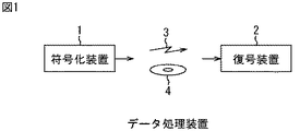
図1は、本発明を適用したデータ処理装置の一実施の形態の構成例を示している。
【0020】
このデータ処理装置は、符号化装置1と復号装置2とで構成されており、符号化装置1は、データを符号化し、その結果得られる符号化データを出力する。
【0021】
符号化装置1が出力する符号化データは、例えば、地上波、衛星回線、CATV(Cable Television)網、インターネット、公衆回線などでなる伝送媒体3を介して伝送され、あるいは、また、例えば、半導体メモリ、光磁気ディスク、磁気ディスク、光ディスク、磁気テープ、相変化ディスクなどでなる記録媒体4に記録され、復号装置2に提供される。
【0022】
復号装置2は、伝送媒体3または記録媒体4を介して提供される符号化データを受信し、その符号化データを復号する。
【0023】
図2は、図1の符号化装置1の構成例を示している。
【0024】
図2の実施の形態では、符号化装置1における符号化対象のデータとして、例えば、画像データや音声データ(曲等の音響データを含む)、テキストデータ等の各種のメディアのメディアデータと、商品やサービス等の広告のための広告データとが供給されるようになっている。
【0025】
このメディアデータと広告データは、統合部11に供給されるようになっており、統合部11は、メディアデータと広告データとを、何らかの方法で1つのデータに統合し、埋め込み部13に供給する。すなわち、例えば、統合部11は、メディアデータに、広告データを埋め込むことにより、そのメディアデータおよび広告データを符号化し、その結果得られる埋め込みデータを、符号化データとして、埋め込み部13に供給する。
【0026】
さらに、統合部11は、メディアデータに、広告データを埋め込むときの埋め込み方式を表す埋め込み方式信号を生成し、プログラムデータ作成部12に供給する。
【0027】
プログラムデータ作成部12は、統合部11からの埋め込み方式信号に基づいて、統合部11が出力する埋め込みデータを、メディアデータと、そのメディアデータに埋め込まれた広告データに復号し、さらに、その提示を行うプログラム(以下、適宜、復号提示プログラムという)を生成して、埋め込み部13に供給する。
【0028】
埋め込み部13は、統合部11からの符号化データに、プログラムデータ作成部12からの復号提示プログラムを埋め込み、その結果得られる埋め込みデータを、最終的な符号化データとして出力する。
【0029】
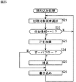
次に、図3のフローチャートを参照して、図2の符号化装置1の処理について説明する。
【0030】
統合部11は、メディアデータと広告データが供給されると、ステップS1において、そのメディアデータに、広告データを埋め込み、その結果得られる埋め込みデータを、メディアデータと広告データの符号化データとして、埋め込み部13に供給する。さらに、統合部11は、ステップS1において、メディアデータに、広告データを埋め込んだときに用いた埋め込み方式を表す埋め込み方式信号を生成し、プログラムデータ作成部12に供給する。
【0031】
プログラムデータ作成部12は、ステップS2において、統合部11からの埋め込み方式信号に基づき、復号提示プログラムを作成し、埋め込み部13に供給する。
【0032】
埋め込み部13は、ステップS3において、統合部11からの符号化データに、プログラムデータ作成部12からの復号提示プログラムを埋め込み、埋め込みデータを生成して、ステップS4に進む。ステップS4では、埋め込み部13は、ステップS3で得られた埋め込みデータを、最終的な符号化データとして出力し、処理を終了する。
【0033】
なお、符号化装置1は、メディアデータと広告データが供給されるごとに、図3のフローチャートにしたがった処理を行う。
【0034】
次に、図4は、図1の復号装置2の構成例を示している。
【0035】
伝送媒体3または記録媒体4(図1)から提供される最終的な符号化データとしての埋め込みデータは、復号部21に供給される。
【0036】
復号部21は、そこに供給される埋め込みデータを、符号化データ(メディアデータに、広告データを埋め込んだ埋め込みデータとしての符号化データ(以下、適宜、中間符号化データという))と、その中間符号化データに埋め込まれている復号提示プログラムに復号し、その中間符号化データおよび復号提示プログラムを、プログラム実行部22に供給する。
【0037】
プログラム実行部22は、復号部23とデータ提示部24から構成され、復号部21からの復号提示プログラムを実行することにより、同じく復号部21からの中間符号化データを、メディアデータと広告データに復号するとともに、それらの提示を行う。
【0038】
即ち、復号部23は、復号部21からの中間符号化データを、メディアデータと、そのメディアデータに埋め込まれている広告データに復号し、データ提示部24に供給する。
【0039】
データ提示部24は、復号部23からのメディアデータおよび広告データを、図示せぬディスプレイに表示し、あるいは図示せぬスピーカから出力する。
【0040】
次に、図5のフローチャートを参照して、図4の復号装置2の処理について説明する。
【0041】
復号部21に対して、埋め込みデータが供給されると、復号部21は、ステップS11において、その埋め込みデータを、中間符号化データと、その中間符号化データに埋め込まれている復号提示プログラムに復号し、その中間符号化データおよび復号提示プログラムを、プログラム実行部22に供給する。
【0042】
プログラム実行部22は、ステップS12において、復号部21からの復号提示プログラムの実行を開始して、ステップS13に進む。これにより、ステップS13では、復号部23が、復号提示プログラムにしたがい、復号部21からの中間符号化データを、メディアデータと、そのメディアデータに埋め込まれている広告データに復号し、データ提示部24に供給し、データ提示部24が、やはり、復号提示プログラムにしたがい、復号部23からのメディアデータおよび広告データを提示して、処理を終了する。
【0043】
なお、復号装置2は、埋め込みデータが供給されるごとに、図5のフローチャートにしたがった処理を行う。
【0044】
以上のように、符号化装置1では、メディアデータに、広告データを埋め込んで埋め込みデータとしての中間符号化データとし、中間符号化データを、メディアデータおよび広告データに復号するのに必要な復号提示プログラムを、中間符号化データに埋め込み、埋め込みデータとしての最終的な符号化データを生成し、一方、復号装置2では、符号化装置1からの埋め込みデータを、中間符号化データと、そこに埋め込まれている復号提示プログラムに復号し、その復号提示プログラムにしたがって、中間符号化データを、メディアデータおよび広告データに復号するようにしたので、ユーザに、広告データを、必然的に見てもらうことができる。
【0045】
即ち、メディアデータと広告データは符号化されており、即ち、ここでは、メディアデータに、広告データが埋め込まれ、埋め込みデータとしての中間符号化データとされており、そのままでは、メディアデータを見る(あるいは、聴く)ことはできない。即ち、メディアデータを見るためには、図6に示すように、まず、埋め込みデータを、中間符号化データと復号提示プログラムに復号し、さらに、中間符号化データを、復号提示プログラムによって、メディアデータと広告データに復号しなければならず、従って、メディアデータと広告データとは、いわばセットでなければ見ることができない。その結果、ユーザが、メディアデータを見ようとすれば、必ず、広告データも見ることになる。
【0046】
さらに、メディアデータと広告データの復号を行うための復号提示プログラムが、中間符号化データに埋め込まれているため(但し、逆に、復号提示プログラムに、中間符号化データを埋め込んでも良い)、後述するように、全体のデータ量の増加を防止することができる。
【0047】
また、復号提示プログラムには、メディアデータおよび広告データの復号だけでなく、その提示を行うプログラムも含まれるため、広告データを、その提供者(広告主)の要求にあった形で、ユーザに提示することが可能となる。
【0048】
なお、メディアデータと広告データの符号化は、埋め込みに限定されるものではなく、その他の符号化方式を採用して、メディアデータと広告データとを、それぞれ符号化することも可能である。しかしながら、このように、メディアデータと広告データを、別個独立に符号化した場合には、例えば、悪意のユーザによって、メディアデータだけの復号が行われるおそれがある。
【0049】
これに対して、メディアデータに、広告データを埋め込むことで(あるいは、逆に、広告データにメディアデータを埋め込むことで)、符号化を行う場合には、メディアデータと広告データとは、いわば統合されたデータとなり、いずれか一方だけを復号することはできなくなる。従って、この場合、上述のような、悪意のユーザによるメディアデータだけの復号が行われることを防止することができる。
【0050】
以上のようなデータ処理装置は、例えば、インターネット等の、ネットワークを介して、データのダウンロードを行うダウンロードシステム等に適用することができる。
【0051】
即ち、この場合、ダウンロードシステムは、例えば、図7に示すように、符号化装置1としてのサーバと、復号装置2としてのクライアントとから構成することができる。
【0052】
図7のダウンロードシステムにおいては、クライアントが、サーバに対して、あるメディアデータのダウンロードを要求すると、サーバは、その要求のあったメディアデータに、広告データを埋め込んで、埋め込みデータとしての中間符号化データを作成し、さらに、その中間符号化データに、復号提示プログラムを埋め込むことで、最終的な符号化データとしての埋め込みデータを生成する。クライアントでは、この埋め込みデータがダウンロードされ、中間符号化データと復号提示プログラムに復号される。さらに、クライアントでは、中間符号化データが、復号提示プログラムにしたがって、メディアデータと広告データに復号され、さらに、そのメディアデータと広告データが、復号提示プログラムにしたがって提示される。
【0053】
従って、クライアント側において、メディアデータを見ようとすれば、広告データを、必ず見ることになるので、図1のデータ処理装置によれば、ネットワーク上の広告ビジネスに付加価値を付けることができる。
【0054】
次に、符号化装置1(図2)を構成する統合部11および13における埋め込み方法、並びに復号装置2(図4)を構成する復号部21および23における復号方法について説明する。
【0055】
埋め込みには、大きく分けて、埋め込みに用いるデータの相関性を利用するものと、利用しないものがある。
【0056】
そこで、まず、データの相関性を利用しない埋め込み方法について説明する。
【0057】
データの相関性を利用しない埋め込み方法としては、例えば、データが埋め込まれる被埋め込み対象データ(例えば、上述のメディアデータや、中間符号化データ)を、所定の符号化ルールにしたがって符号化するとともに、その符号化ルールを、被埋め込み対象データに埋め込まれる埋め込み対象データ(例えば、上述の広告データや、復号提示プログラム)に基づいて破壊することにより、その埋め込み対象データを、被埋め込み対象データに埋め込む方法がある。
【0058】
図8は、そのような埋め込みを行う場合の、図2の統合部11(または埋め込み部13)の第1の構成例を示している。
【0059】
メモリ31は、統合部11に供給される被埋め込み対象データを、所定の単位で記憶する。メモリ32は、統合部11に供給される埋め込み対象データを、所定の単位で記憶する。
【0060】
可変長符号化部33は、メモリ31に記憶された被埋め込み対象データを、可変長符号化としての、例えば、ハフマン符号化し、その結果得られる符号化データを、符号化ルール破壊部25に供給する。また、可変長符号化部33は、ハフマン符号化の際、後述するようにして、ハフマンテーブルを作成するが、そのハフマンテーブルを、変換テーブル作成部34に供給する。さらに、可変長符号化部33は、変換テーブル作成部34に出力したハフマンテーブルを得るのに必要な情報としてのハフマンテーブル関連情報を、MUX(マルチプレクサ)36に供給する。
【0061】
変換テーブル作成部34は、可変長符号化部33から供給されるハフマンテーブルにおける符号を変換するための変換テーブルを、メモリ32に記憶された埋め込み対象データに基づいて作成する。即ち、ハフマンテーブルは、ハフマン符号化する対象の値(ここでは、被埋め込み対象データ)と、各符号長の符号(符号化データ)との対応関係を記述したものであるが、変換テーブル作成部34は、そのようなハフマンテーブルにおける符号を、埋め込み対象データに基づく符号に変換するための変換テーブルを作成する。変換テーブル作成部34で作成された変換テーブルは、符号化ルール破壊部35に供給される。
【0062】
符号化ルール破壊部35は、埋め込み対象データに基づき、可変長符号化部33における符号化ルールを破壊することにより、符号化された被埋め込み対象データに、埋め込み対象データを埋め込む。即ち、符号化ルール破壊部35は、変換テーブル作成部34が埋め込み対象データに基づき作成した変換テーブルにしたがって、可変長符号化部33が出力する符号化データ(符号)を変換(操作)し、可変長符号化部33における符号化ルールを破壊した符号化ルールにより符号化された符号化データを得る。この破壊された符号化ルールにより符号化された符号化データは、元の符号化データに、埋め込み対象データが埋め込まれた埋め込み符号化データとして、符号化ルール破壊部35からMUX36に供給される。
【0063】
MUX36は、符号化ルール破壊部35からの埋め込み符号化データと、可変長符号化部33からのハフマンテーブル関連情報とを多重化し、その結果得られる多重化データを、被埋め込み対象データに埋め込み対象データを埋め込んだ埋め込みデータとして出力する。
【0064】
次に、図9は、図8の可変長符号化部33の構成例を示している。
【0065】
図8のメモリ31においては、そこに記憶された所定単位の被埋め込み対象データが読み出され、頻度テーブル作成部41と符号化部44に供給される。
【0066】
頻度テーブル作成部41は、そこに供給される被埋め込み対象データについて、その各値と、その出現頻度とを対応付けた頻度テーブルを作成し、ハフマン木作成部42に供給する。また、頻度テーブルは、ハフマンテーブル関連情報として、頻度テーブル作成部41から、図9のMUX36に供給される。
【0067】
ここで、図9の実施の形態では、頻度テーブルを、ハフマンテーブル関連情報として用いるようにしたが、ハフマンテーブル関連情報は、後述するハフマンテーブル作成部43が作成するハフマンテーブルを得ることができるような情報であれば、特に限定されるものではなく、従って、ハフマンテーブル関連情報としては、頻度テーブルの他、例えば、ハフマンテーブル作成部43が作成するハフマンテーブルそのもの等を用いることが可能である。
【0068】
ハフマン木作成部42は、頻度テーブル作成部41から供給される頻度テーブルに基づいて、いわゆるハフマン木を作成し、ハフマンテーブル作成部43に供給する。ハフマンテーブル作成部43は、ハフマン木作成部42からのハフマン木に基づき、ハフマンテーブルを作成する。即ち、ハフマンテーブル作成部43は、被埋め込み対象データに対して、その値の出現頻度が高いほど、短い符号長の符号(出現頻度が低いほど長い符号長の符号)が割り当てられたハフマンテーブルを作成する。このハフマンテーブルは、符号化部44に供給されるとともに、図8の変換テーブル作成部34に供給される。
【0069】
符号化部44は、そこに供給される被埋め込み対象データの各値を、ハフマンテーブル作成部43からのハフマンテーブルにおいて対応付けられている符号に変換し、これにより、可変長符号化データを得て出力する。
【0070】
以上のように構成される可変長符号化部33では、頻度テーブル作成部41において、被埋め込み対象データについて頻度テーブルが作成され、ハフマン木作成部42に供給される。ハフマン木作成部42では、頻度テーブル作成部41からの頻度テーブルに基づいて、ハフマン木が作成され、ハフマンテーブル作成部43に供給される。ハフマンテーブル作成部43では、ハフマン木作成部42からのハフマン木に基づき、ハフマンテーブルが作成され、符号化部44に供給される。符号化部44では、被埋め込み対象データの各値が、ハフマンテーブルにおいて、その値に対応付けられている符号に変換され、その結果得られる可変長符号化データが出力される。
【0071】
次に、図10を参照して、可変長符号化部33における可変長符号化処理について、さらに説明する。
【0072】
いま、頻度テーブル作成部41において、例えば、図10(A)に示すような頻度テーブルが作成されたとする。ここで、図10(A)は、被埋め込み対象データにおいて、値「0」、「1」、「2」、「3」、「4」が、それぞれ、5,4,3,2,1回ずつ現れていることを表している。
【0073】
図10(A)の頻度テーブルについては、ハフマン木作成部42において、例えば、図10(B)乃至図10(E)に示すように、被埋め込み対象データの各値の出現頻度に基づき、いわばボトムアップ式に、ハフマン木が作成される。
【0074】
即ち、ハフマン木作成部42は、頻度テーブルにおける値の中から、出現頻度が最も低いものを2つ選択し、1つの接点を構成する。さらに、ハフマン木作成部42は、選択した2つの値のうちの、出現頻度が低い方に、ビット"0"または"1"のうちの、例えば、"0"を割り当て、他方に、"1"を割り当てる。そして、ハフマン木作成部42は、選択した2つの値によって構成した接点に対して、その選択した2つの値の出現頻度の加算値を、その接点の出現頻度として割り当てる。
【0075】
従って、図10(A)に示した頻度テーブルにおいては、図10(B)に示すように、出現頻度が1の値「4」と、出現頻度が2の値「3」が選択され、接点#1が構成されるとともに、その接点#1の出現頻度として、3(=1+2)が割り当てられる。さらに、選択された2つの値「4」と「3」のうち、出現頻度が低い方の値「4」に、ビット"0"が割り当てられるとともに、出現頻度が高い方の値「3」に、ビット"1"が割り当てられる。
【0076】
ここで、図10(B)乃至図10(E)では、出現頻度を表す数字を、カッコ()で囲って表してある。
【0077】
なお、選択された2つの値の出現頻度が同一の場合には、いずれの値に、ビット"0"または"1"を割り当てても良い。但し、例えば、値が小さい方に、ビット"0"を割り当てるといったように、どちらの値に、ビット"0"または"1"を割り当てるかを、あらかじめ決めておく必要がある。
【0078】
ハフマン木作成部42では、以下、同様の処理が、接点が1つ収束するまで繰り返される。
【0079】
従って、図10(B)の状態からは、図10(C)に示すように、出現頻度がいずれも3の接点#1と値「2」が選択され、その接点#1と値「2」が、1つの接点#2とされる。さらに、接点#2の出現頻度が6(=3+3)とされ、接点#1と値「2」には、それぞれビット"0"と"1"が割り当てられる。
【0080】
図10(C)の状態からは、図10(D)に示すように、出現頻度が4の値「1」と、出現頻度が5の値「0」が選択され、その値「1」と「0」が、1つの接点#3とされる。さらに、接点#3の出現頻度が9(=4+5)とされ、値「1」と「0」には、それぞれビット"0"と"1"が割り当てられる。
【0081】
図10(D)の状態からは、図10(E)に示すように、出現頻度が6の接点#2と、出現頻度が9の接点#3が選択され、その接点#2と#3が、1つの接点#4とされる。さらに、接点#4の出現頻度が15(=6+9)とされ、接点#2と#3には、それぞれビット"0"と"1"が割り当てられる。
【0082】
図10(E)の状態では、接点が、1つの接点#4に収束しているので、ハフマン木の完成となり、ハフマン木作成部42は、このハフマン木を、ハフマンテーブル作成部43に供給する。
【0083】
ハフマンテーブル作成部43は、ハフマン木を、収束した接点から、値の方向に辿っていくことで、各値に割り当てられた符号を認識する。
【0084】
即ち、例えば、図10(E)に示したハフマン木を、接点#4から、値「0」の方向に辿っていき、各接点(または値)に割り当てられたビットを並べると、"0"→"0"→"0"となる。これにより、ハフマンテーブル作成部43は、値「0」に対して、符号"000"が割り当てられたことを認識する。また、図10(E)に示したハフマン木を、接点#4から、値「1」の方向に辿っていき、各接点に割り当てられたビットを並べると、"0"→"0"→"1"となる。これにより、ハフマンテーブル作成部43は、値「1」に対して、符号"001"が割り当てられたことを認識する。
【0085】
以下、同様にして、ハフマンテーブル作成部43は、各値に割り当てられた符号を認識し、被埋め込み対象データの各値と符号との対応関係を表すハフマンテーブルを作成する。従って、図10(E)に示したハフマン木からは、図10(F)に示すようなハフマンテーブルが作成されることになる。
【0086】
図10(E)に示したハフマンテーブルにおいては、出現頻度が5,4,3,2,1回の値「0」、「1」、「2」、「3」、「4」それぞれに、符号"11","10","01","001","000"が割り当てられており、従って、基本的に、出現頻度が高いほど、符号長の短い符号が割り当てられている。
【0087】
ところで、図10(E)のハフマンテーブルにおいては、値「0」、「1」、「2」、「3」、「4」の出現頻度は異なるが、出現頻度が比較的高い値「0」、「1」、「2」には、2ビットの符号が割り当てられており、出現頻度が比較的低い値「3」、「4」には、3ビットの符号が割り当てられている。
【0088】
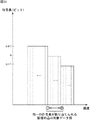
このように、ハフマンテーブルにおいては、出現頻度が異なっていても、同一の符号長の符号が割り当てられる場合があり、値の出現頻度と、その値に割り当てられる符号の符号長との関係は、一般に、図11に示すようになる。
【0089】
いま、図11において、nビットの符号が割り当てられる値がx個あるとすると(但し、xは2n以下の整数)、そのx個の値に対するnビットの符号の割り当てパターンは、x!パターンだけ存在するが(!は階乗を表す)、ハフマンテーブルにおいては、そのx!パターンのうちの1つだけが、上述したハフマン木を作成する際のルールに基づいて採用されているにすぎない。
【0090】
一方、ハフマンテーブルにおける、x個の値に対するnビットの符号の割り当てパターンを変更しても、符号量は増加しない。即ち、ハフマンテーブルにおいて、nビットのある符号が割り当てられるある値に、他のnビットの符号を割り当てても、割り当てられる符号長は、nビットのままであるから、符号量は増加しない。
【0091】
さらに、ハフマンテーブルにおける、x個の値に対するnビットの符号の割り当てパターンを変更しても、例えば、そのx個の値の出現頻度に基づいて、符号の割り当てパターンは、元に戻すことができる。
【0092】
以上から、ハフマンテーブルにおいて同一の符号長の符号が割り当てられている値に対する符号の割り当てパターンを変更しても、即ち、可変長符号化の符号化ルールを破壊しても、符号量は増加せず、さらに、変更後の割り当てパターンは、元に戻すことができる。
【0093】
このことは、被埋め込み対象データの各値に対する符号の割り当てパターンの変更を、何らかの情報に基づいて行うことで、全体のデータ量を増加させずに、情報を埋め込むことができ、かつ、その埋め込んだ情報を、オーバヘッドなしで復号することができることを意味する。
【0094】
即ち、図12は、8ビットで表される被埋め込み対象データの各値(0乃至255)について作成されたハフマンテーブルの例を示している。なお、図12においては、各値と、その値に割り当てられた符号(可変長符号化データ)の他、各値の出現頻度も示してある。
【0095】
図12において、例えば、値「12」乃至「18」の7つの値に注目すると、これらの7つの値には、いずれも、9ビットの符号が割り当てられており、この7つの値に対する9ビットの符号の割り当て方は、7!パターンだけ存在する。従って、この7つの値に対する9ビットの符号の割り当てパターンを変更することで、int[log27!]ビットの情報を埋め込むことができる。なお、int[]は、[]内の値以下の最大の整数値を意味する。
【0096】
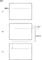
ここで、図13(A)は、図12における値「12」乃至「18」それぞれの出現頻度をグラフによって表したものであり、図13(B)は、図12において、値「12」乃至「18」それぞれに割り当てられた9ビットの符号(可変長符号化データ)を表している。
【0097】
いま、図13(B)に示した符号の割り当てを、int[log27!]ビット以下の埋め込み対象データに基づいて、例えば、図13(C)に示すように変更したとする。
【0098】
即ち、図13(B)においては、値「12」乃至「18」に対して、符号"110111111","110111010","110100001","110011001","11011000","011101011","010001010"が、それぞれ割り当てられており、図13(C)では、値「12」に割り当てられていた符号"110111111"が値「15」に、値「15」に割り当てられていた符号"110011001"が値「12」に、値「16」に割り当てられていた符号"11011000"が値「17」に、値「17」に割り当てられていた符号"011101011"が値「18」に、値「18」に割り当てられていた符号"010001010"が値「16」に、それぞれ割り当て変更されている。なお、図13では、他の値に対する符号の割り当ては、変更されていない。
【0099】
ここで、他の符号長の符号が割り当てられた値についても、符号の割り当てパターンを、埋め込み対象データに基づいて変更することができる。図14に、埋め込み対象データに基づいて、図12における符号の割り当てパターンを変更した可変長符号化データである埋め込み符号化データの例を示す。なお、図14には、埋め込み符号化データとともに、その埋め込み符号化データを、図12に示したハフマンテーブルにしたがって可変長復号を行うことにより得られる復号値(埋め込み符号化データを、正しい可変長符号化データを得るときに用いたハフマンテーブルによって復号した値)も示してある。
【0100】
図14において、例えば、値「12」乃至「18」の7つの値に注目し、埋め込み符号化データを、図12のハフマンテーブルにしたがって復号すると、図15(A)に示すような復号値が得られる。即ち、埋め込み符号化データを、符号化時に用いたハフマンテーブルにしたがって復号した値を、埋め込み復号値というものとすると、符号"110011001","110111010","110100001","110111111","010001010","11011000","011101011"は、埋め込み復号値「15」、「13」、「14」、「12」、「18」、「16」、「17」に、それぞれ可変長復号される。
【0101】
この埋め込み復号値「12」乃至「18」について、その出現頻度をカウントすると、図15(B)に示すようになる。即ち、図12のハフマンテーブルにおいて、値「12」乃至「18」に対して割り当てられた符号を、図13(B)および図13(C)に示したように変更したことから、値「12」、「15」、「16」乃至「18」については、その出現頻度が、図13(A)に示したものに一致せず、具体的には、可変長符号化前の値「15」、「12」、「18」、「16」、「17」の出現頻度にそれぞれ一致したものとなる。
【0102】
しかしながら、元(可変長符号化前)の値「12」乃至「18」それぞれの出現頻度と、可変長復号の結果得られる値「12」乃至「18」それぞれの出現頻度とは一致するはずであるから、上述のように、値の出現頻度が、可変長符号化前と、可変長復号後とで異なるのはおかしい。
【0103】
そこで、図13(A)に示した元の値の出現頻度と、図15(B)に示した埋め込み復号値の出現頻度とを比較し、一致する出現頻度を検出することで、埋め込み対象データに基づいて変更された符号(可変長符号)の割り当てパターンを元に戻すことができる。即ち、埋め込み符号化データを、ハフマンテーブルに基づいて符号化された可変長符号化データに戻すことができる。そして、埋め込み符号化データを可変長符号化データに戻すときの符号の割り当てパターンの変更の仕方から、被埋め込み対象データ(可変長符号化データ)に埋め込まれた埋め込み対象データを復号することができ、また、元に戻した可変長符号化データを可変長復号することで、被埋め込み対象データの元の値を復号することができる。
【0104】
具体的には、図13(A)に示した元の値の出現頻度と、図15(B)に示した埋め込み復号値の出現頻度とを比較することで、埋め込み復号値「15」、「13」、「14」、「12」、「17」、「18」、「16」の出現頻度が、元の値「12」乃至「18」の出現頻度とそれぞれ一致することを検出することができる。
【0105】
これにより、埋め込み復号値「15」、「13」、「14」、「12」、「17」、「18」、「16」が得られた埋め込み符号化データ"110011001","110111010","110100001","110111111","010001010","11011000","011101011"は、埋め込み対象データが埋め込まれる前は、図12のハフマンテーブルにおいて、元の値「12」乃至「18」に割り当てられている符号"110111111","110111010","110100001","110011001","11011000","011101011","010001010"であったことが分かる。
【0106】
従って、図15(C)に示すように、図13(A)に示した元の値の出現頻度と、図15(B)に示した埋め込み復号値の出現頻度が一致するように、埋め込み符号化データを変換することにより、図12に示したハフマンテーブルにしたがって符号化された可変長符号化データを復元するとともに、埋め込み符号化データと、復元された可変長符号化データとの対応関係から、埋め込み対象データを復号することができる。さらに、復元された可変長符号化データを可変長復号することで、図15(D)に示すように、被埋め込み対象データの元の値を復号することができる。
【0107】
図8の統合部11では、以上のように、データ量を増加させずに、オーバヘッドなしの復号が可能な埋め込み符号化処理が行われる。
【0108】
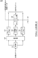
次に、図16は、図2の統合部11(または13)が図8に示したように構成される場合の、図4の復号部21(または復号部23)の構成例を示している。
【0109】
DEMUX(デマルチプレクサ)51には、図8の統合部11が多重化データとして出力する埋め込みデータとハフマンテーブル関連情報との多重化結果が供給され、DEMUX51は、その多重化データを、埋め込み符号化データとハフマンテーブル関連情報とに分離し、埋め込み符号化データを、可変長復号部52および符号化ルール復元部55に供給するとともに、ハフマンテーブル関連情報を、可変長復号部52、逆変換テーブル作成部54、および可変長復号部56に供給する。
【0110】
可変長復号部52は、DEMUX51が出力する埋め込み符号化データおよびハフマン関連情報を受信し、ハフマンテーブル関連情報としての頻度テーブルから、図9の可変長符号化部33における場合と同様にして、ハフマンテーブルを作成して、逆変換テーブル作成部54に供給する。
【0111】
ここで、ハフマンテーブル関連情報としての頻度テーブルから作成されるハフマンテーブルは、図8の可変長符号化部33での可変長符号化に用いられるものと同一のものであり、以下、適宜、正ハフマンテーブルという。また、正ハフマンテーブルを得るのに用いられるハフマンテーブル関連情報としての頻度テーブルを、以下、適宜、正頻度テーブルという。
【0112】
可変長復号部52は、さらに、埋め込み符号化データを、正ハフマンテーブルにしたがって可変長復号し、その結果得られる被埋め込み対象データの復号値(埋め込み復号値)を、ハフマンテーブル生成部53に供給する。
【0113】
ハフマンテーブル生成部53は、可変長復号部52から供給される埋め込み復号値を可変長符号化するハフマンテーブルを作成し、そのハフマンテーブルと、そのハフマンテーブルを作成する過程で作成される頻度テーブルを、逆変換テーブル作成部54に供給する。
【0114】
ここで、ハフマンテーブル生成部53が作成するハフマンテーブルは、埋め込み復号値(埋め込み符号化データを、正ハフマンテーブルによって可変長復号したもの)を可変長符号化するものであり、基本的に、正しい可変長符号化データを正しく復号することができるものではない。そこで、この埋め込み復号値から得られるハフマンテーブルを、以下、適宜、正ハフマンテーブルに対して、誤ハフマンテーブルという。また、誤ハフマンテーブルを得るのに用いられる頻度テーブルを、以下、適宜、正頻度テーブルに対して、誤頻度テーブルという。
【0115】
逆変換テーブル作成部54は、可変長復号部52からの正ハフマンテーブル、DEMUX51からのハフマンテーブル関連情報としての正頻度テーブル、ハフマンテーブル生成部53からの誤ハフマンテーブルおよび誤頻度テーブルに基づいて、埋め込み符号化データを、元の可変長符号化データに変換するための逆変換テーブルを作成する。即ち、逆変換テーブル作成部54は、図8の変換テーブル作成部34が作成する変換テーブルと同一の逆変換テーブルを作成する。この逆変換テーブルは、符号化ルール復元部55に供給される。
【0116】
符号化ルール復元部55は、逆変換テーブル作成部54から供給される逆変換テーブルに基づき、DEMUX51からの埋め込み符号化データを、符号化ルールとしての正ハフマンテーブルにしたがって符号化された可変長符号化データに復元する。さらに、符号化ルール復元部55は、埋め込み符号化データと、復元した可変長符号化データとの対応関係、即ち、逆変換テーブルに基づいて、埋め込み符号化データに埋め込まれていた埋め込み対象データを復号する。そして、符号化ルール復元部55は、復元した可変長符号化データを、可変長復号部56に出力するとともに、復号した埋め込み対象データを、復号埋め込み対象データとして出力する。
【0117】
可変長復号部56は、DEMUX51から供給されるハフマン関連情報から、正ハフマンテーブルを作成し、その正ハフマンテーブルに基づいて、符号化ルール復元部55から供給される可変長符号化データを可変長復号して、その結果得られる被埋め込み対象データの復号値(以下、適宜、復号被埋め込み対象データという)を出力する。
【0118】
次に、図17は、図16の可変長復号部52の構成例を示している。
【0119】
DEMUX51が出力する埋め込み符号化データは、復号部63に供給されるようになっており、同じく、DEMUX51が出力するハフマンテーブル関連情報としての頻度テーブルは、ハフマン木作成部61に供給されるようになっている。
【0120】
ハフマン木作成部61は、図9のハフマン木作成部42と同様に、頻度テーブルから、ハフマン木を作成し、ハフマンテーブル作成部62に供給する。
【0121】
ハフマンテーブル作成部62は、図9のハフマンテーブル作成部43と同様に、ハフマン木作成部61からのハフマン木に基づいて、ハフマンテーブルを作成し、復号部63に供給する。
【0122】
復号部63は、ハフマンテーブル作成部62からのハフマンテーブルにしたがい、そこに供給される埋め込み符号化データを、可変長復号出力する。
【0123】
なお、図16の可変長復号部56も、図17に示した可変長復号部52と同様に構成される。
【0124】
次に、図18は、図16のハフマンテーブル生成部53の構成例を示している。
【0125】
ハフマンテーブル生成部53において、可変長復号部52が出力する埋め込み復号値は、頻度テーブル71に供給される。頻度テーブル71、ハフマン木作成部72、またはハフマンテーブルテーブル作成部73は、図9の頻度テーブル作成部41、ハフマン木作成部42、またはハフマンテーブル作成部43における場合とそれぞれ同様の処理を行う。
【0126】
これにより、頻度テーブル作成部71では、埋め込み復号値についての頻度テーブルである誤頻度テーブル(被埋め込み対象データの元の値についての頻度テーブルではない)が作成され、逆変換テーブル作成部54(図16)に供給される。また、ハフマンテーブル作成部73では、埋め込み復号値を、その出現頻度に応じた符号長の符号に変換するためのハフマンテーブルである誤ハフマンテーブル(被埋め込み対象データの元の値についてのハフマンテーブルではない)が作成され、逆変換テーブル作成部54に供給される。
【0127】
次に、図19は、図16の逆変換テーブル作成部54の構成例を示している。
【0128】
逆変換テーブル作成部54には、上述したように、正ハフマンテーブル、正頻度テーブル、誤ハフマンテーブル、および誤頻度テーブルが供給されるようになっており、逆変換テーブル作成部54では、これらのテーブルに基づき、図12乃至図15で説明したようにして、埋め込み符号化データと、正ハフマンテーブルによって符号化された可変長符号化データとの対応関係が認識され、その対応関係が記述された逆変換テーブルが作成される。
【0129】
正ハフマンテーブルおよび誤ハフマンテーブルは、符号対応付け部82に供給され、正頻度テーブルおよび誤頻度テーブルは、比較部81に供給される。
【0130】
そして、比較部81は、正頻度テーブルと誤頻度テーブルとを比較し、各符号長の符号ごとに、正頻度テーブルと誤頻度テーブルにおいて、同一の頻度となっている値を検出する。さらに、比較部81は、正頻度テーブルと誤頻度テーブルにおいて、同一の頻度となっている値を対応付けた対応値テーブルを作成し、符号対応付け部82に供給する。
【0131】
符号対応付け部82は、比較部81からの対応値テーブルにおいて対応付けられている値を、正ハフマンテーブルと誤ハフマンテーブルから検索し、その検索した値に対応付けられている符号どうしを対応付けることにより、逆変換テーブルを作成する。この逆変換テーブルは、符号化ルール復元部55に供給される。
【0132】
次に、図20は、被埋め込み対象データを、所定の符号化ルールにしたがって符号化するとともに、その符号化ルールを、埋め込み対象データに基づいて破壊することにより、その埋め込み対象データを、被埋め込み対象データに埋め込む場合の、図2の統合部11(または埋め込み部13)の第2の構成例を示している。
【0133】
符号化部91には、被埋め込み対象データが供給されるようになっており、符号化部91は、被埋め込み対象データを、所定の符号化ルールにしたがって符号化し、その結果得られる符号化データを、埋め込み部92に出力する。
【0134】
埋め込み部92には、埋め込み対象データが供給されるようになっており、埋め込み部92は、符号化部91から供給される符号化データを、埋め込み対象データに基づいて操作して、破壊された符号化ルールにしたがって符号化された符号化データとすることにより、その埋め込み対象データを、符号化された被埋め込み対象データに埋め込み、埋め込み符号化データを出力する。
【0135】
次に、図21は、図20の符号化部91の構成例を示している。なお、ここでは、例えば、被埋め込み対象データが、画像データであるとし、さらに、その画像データを構成する画素値が、RGB(Red,Green,Blue)で表現されるものとする。
【0136】
図21の符号化部91においては、被埋め込み対象データとしての各画素値が、RGBの色空間においてベクトル量子化され、セントロイドベクトルを表すコード(以下、適宜、VQコードという)、そのコードに対応するセントロイドベクトルで表される画素値の、元の画素値に対する誤差(以下、適宜、VQ残差という)、およびベクトル量子化に用いられたコードブックが、符号化データとして出力されるようになっている。
【0137】
即ち、被埋め込み対象データは、フレームメモリ101に供給され、フレームメモリ101は、そこに供給される被埋め込み対象データである画像データを、例えば、フレーム単位で、順次記憶する。
【0138】
コードブック作成部102は、フレームメモリ101に記憶された被埋め込み対象データのフレームを、順次、注目フレームとし、その注目フレームを構成する各画素の画素値から、その色空間におけるベクトル量子化に用いるコードブックを、例えば、いわゆるLBG(Linde,Buzo,Gray)アルゴリズムによって作成する。このコードブックは、ベクトル量子化部103に供給されるとともに、符号化データ(の一部)として出力される。
【0139】
ベクトル量子化部103は、フレームメモリ101から注目フレームを読み出し、その注目フレームを構成する各画素を、例えば、ラスタスキャン順に、順次、注目画素とする。そして、ベクトル量子化部103は、注目画素の画素値を、コードブック作成部102からのコードブックを用いてベクトル量子化し、その結果得られるVQコードおよびVQ残差を、符号化データ(の一部)として出力する。
【0140】
次に、図22は、符号化部91が図21に示したように構成される場合の、図20の埋め込み部92の構成例を示している。
【0141】
符号化部91が出力する符号化データとしての注目フレームのVQコード、VQ残差、コードブックは、VQコードメモリ111、VQ残差メモリ112、コードブックメモリ113に、それぞれ供給されて記憶される。
【0142】
VQコードメモリ111とコードブックメモリ113にそれぞれ記憶されたVQコードとコードブックは、そこから読み出され、圧縮部115に供給される。
【0143】
一方、ラインローテーション部114は、注目フレームの各ライン(水平ライン)を、例えば、上から下方向に、順次、注目ラインとし、その注目ラインについて、VQ残差メモリ112に記憶されたVQ残差を読み出す。さらに、ラインローテーション部114は、注目ラインを構成する画素数を、xとすると、int[log2x]で表されるビット数の埋め込み対象データを受信し、例えば、図23に示すように、その埋め込み対象データに対応する画素数だけ、注目ラインのVQ残差を右ローテーションすることにより、その埋め込み対象データを、注目ラインに埋め込む。即ち、このラインローテーションにより、注目ライン上のある画素に注目すれば、基本的に、その画素についてのVQ残差は、ベクトル量子化により得られるものとは異なるものとなり、ベクトル量子化の符号化ルールが破壊される。そして、符号化ルールが破壊されることにより、埋め込み対象データが埋め込まれる。
【0144】
その後、ラインローテーション部114は、埋め込み対象データを埋め込んだ注目ラインのVQ残差を、圧縮部115に供給する。
【0145】
ここで、注目ラインのVQ残差を右ローテーションする場合、注目ラインの右端の画素のVQ残差は、注目ラインの左端の画素にローテーションされるものとする。同様に、注目ラインのVQ残差を左ローテーションする場合、左端の画素のVQ残差は、右端の画素にローテーションされるものとする。
【0146】
圧縮部115は、そこに供給されるVQコード、VQ残差、コードブックを、例えば、空間相関やエントロピーの偏り等を利用して圧縮し、その圧縮結果を、MUX116に出力する。MUX116は、圧縮部115からのVQコード、VQ残差、コードブックそれぞれの圧縮結果を多重化し、その結果得られる多重化データを、埋め込み符号化データとして出力する。
【0147】
次に、図24は、図2の統合部11(または埋め込み部13)が図20に示したように構成される場合の、図4の復号部21(または復号部23)の構成例を示している。
【0148】
図20の埋め込み部92が多重化データとして出力する埋め込み符号化データは、符号化ルール復元部121に供給される。
【0149】
符号化ルール復元部121は、埋め込み符号化データを、図20の符号化部91における符号化ルールにしたがって符号化された、正しい符号化データに復元し、これにより、埋め込み符号化データに埋め込まれていた埋め込み対象データを復号する。
【0150】
即ち、符号化ルール復元部121は、埋め込み符号化データに対して、パラメータコントローラ124から供給されるパラメータに基づく操作を施すことにより、正しい符号化データの候補(以下、適宜、仮符号化データという)を求める。さらに、符号化ルール復元部121は、埋め込み符号化データを仮符号化データに復元する操作に基づいて、埋め込み符号化データに埋め込まれていた埋め込み対象データの候補(以下、仮復号埋め込み対象データという)を復号する。そして、仮符号化データは、復号部122および判定部123に、仮復号埋め込み対象データは、判定部123に供給される。
【0151】
復号部122は、符号化ルール復元部121からの仮符号化データに対して、図20の符号化部91における符号化ルールに基づく復号処理を施すことにより、元の画素値の候補(以下、適宜、仮復号画素値という)を復号する。この仮復号画素値は、判定部123に供給される。
【0152】
判定部123は、パラメータコントローラ124を制御することにより、1つ以上の値のパラメータを、符号化ルール復元部121に供給させ、その1つ以上の値のパラメータそれぞれに対応して得られる1つ以上の仮復号画素値の中から、正しい(元の画素値に一致する)仮復号画素値を判定する。さらに、判定部123は、1つ以上の仮復号画素値それぞれに付随して、符号化ルール復元部121から供給される1つ以上の仮復号埋め込み対象データの中から、正しい復号画素値が得られたときのものを、正しい復号埋め込み対象データとして選択し、正しい仮復号画素値と仮復号埋め込み対象データを、被埋め込み対象データと埋め込み対象データの最終的な復号結果(復号被埋め込み対象データと復号埋め込み対象データ)として、それぞれ出力する。
【0153】
パラメータコントローラ124は、判定部123の制御にしたがい、埋め込み符号化データを操作するための所定のパラメータを、符号化ルール復元部121に供給する。
【0154】
次に、図25は、図20の埋め込み部92が図22に示したように構成される場合の、図24の符号化ルール復元部121の構成例を示している。
【0155】
図22のMUX116が出力する多重化データとしての埋め込み符号化データは、DEMUX131に供給され、DEMUX131は、そこに供給される埋め込み符号化データを、圧縮されたVQコード、VQ残差、およびコードブックに分離し、伸張部132に供給する。伸張部132は、DEMUX131からの、圧縮されたVQコード、VQ残差、コードブックを伸張し、その伸張後のVQコード、VQ残差、コードブックを、VQコードメモリ133、VQ残差メモリ134、コードブックメモリ135にそれぞれ供給する。
【0156】
VQコードメモリ133、VQ残差メモリ134、コードブックメモリ135は、伸張部132からのVQコード、VQ残差、コードブックを、それぞれ、フレーム単位で記憶する。
【0157】
ラインローテーション部136は、VQ残差メモリ134に記憶されたフレームの各ラインを、例えば、上から下方向に、順次、注目ラインとし、その注目ラインについて、VQ残差メモリ134に記憶されたVQ残差を読み出す。さらに、ラインローテーション部136は、注目ラインを構成する画素数を、xとすると、0乃至xの範囲の整数値を、パラメータコントローラ124(図24)から、パラメータとして受信し、そのパラメータに対応する画素数だけ、注目ラインのVQ残差を左ローテーションする。そして、ラインローテーション部136は、そのローテーション後の各ラインのVQ残差を、VQコードメモリ133に記憶されたVQコード、およびコードブックメモリ135に記憶されたコードブックとともに、仮符号化データとして出力する。
【0158】
さらに、ラインローテーション部136は、パラメータコントローラ124からのパラメータの値を、仮復号埋め込み対象データとして出力する。
【0159】
次に、図26は、図20の符号化部91が図21に示したように構成される場合の、図24の復号部122の構成例を示している。
【0160】
復号部122は、符号化ルール復元部121から供給される符号化データとしての1フレームのVQコード、VQ残差、およびコードブックに基づき、ベクトル逆量子化を行うことにより、画素値を復号する。
【0161】
即ち、ベクトル逆量子化部141には、VQコードおよびコードブックが供給されるようになっており、ベクトル逆量子化部141は、VQコードに対応するセントロイドベクトルを、コードブックから検出し、そのセントロイドベクトルを、加算部142に供給する。加算部142には、ベクトル逆量子化部141からセントロイドベクトルが供給される他、VQ残差としての差分ベクトルも供給されるようになっており、加算部142は、セントロイドベクトルと差分ベクトルとを加算する。そして、加算部142は、その加算の結果得られるベクトルの各成分を、R,G,B値とする画素値を、仮復号画素値として出力する。
【0162】
次に、図27は、符号化ルール復元部121と復号部122が、図25と図26に示したようにそれぞれ構成される場合の、図24の判定部123の構成例を示している。
【0163】
メモリ151には、符号化ルール復元部121からの仮復号埋め込み対象データと、復号部122からの仮復号画素値が供給されるようになっており、メモリ151は、その仮復号埋め込み対象データと仮復号画素値を一時記憶するとともに、正誤判定部154の制御にしたがい、記憶した仮復号埋め込み対象データと仮復号画素値を読み出し、それぞれを、復号埋め込み対象データと復号被埋め込み対象データとして出力する。
【0164】
符号化部152には、符号化ルール復元部121が出力する仮符号化データのうちのコードブックと、復号部122が出力する仮復号画素値が供給されるようになっており、符号化部152は、仮復号画素値を、図20の符号化部91と同様に符号化する。即ち、符号化部152は、仮復号画素値を、符号化ルール復元部121からのコードブックを用いてベクトル量子化し、その結果得られるVQコードとVQ残差を、比較部153に供給する。ここで、以下、適宜、仮復号画素値をベクトル量子化して得られるVQコードとVQ残差を、それぞれ、仮VQコードと仮VQ残差という。
【0165】
比較部153には、符号化部152が出力する仮VQコードおよび仮VQ残差の他、復号部122が出力する仮符号化データのうちのVQコードおよびVQ残差が供給されるようになっている。比較部153は、仮VQコードと、仮符号化データのVQコードとを比較するとともに、仮VQ残差と、仮符号化データのVQ残差とを比較し、それぞれの比較結果を、正誤判定部154に供給する。
【0166】
正誤判定部154は、パラメータコントローラ124を制御することにより、パラメータコントローラ124に、ラインローテーションを行うビット数を、パラメータとして、符号化ルール復元部121に供給させる。また、正誤判定部154は、比較部153からの仮VQコードと仮符号化データのVQコードとの比較結果、および仮VQ残差と仮符号化データのVQ残差との比較結果に基づいて、仮復号画素値が復号結果として正しいかどうかを判定し、その判定結果に基づき、メモリ151からの仮復号画素値および仮復号埋め込み対象データの読み出しを制御する。
【0167】
次に、図28を参照して、図27の正誤判定部154が、仮復号画素値が復号結果として正しいかどうかを判定する判定原理について説明する。
【0168】
符号化部91(図20)では、RGB空間においてベクトル量子化が行われるから、そのベクトル量子化に用いられるセントロイドベクトルは、R成分、B成分、およびG成分の3つの成分から構成される。いま、このR成分、B成分、およびG成分からなるセントロイドベクトルを、(R,G,B)と表すとともに、説明を簡単にするために、コードブックにおけるセントロイドベクトルのR成分、B成分、およびG成分が、いずれも10の倍数で表されるものとすると、R,B,G成分が、例えば、それぞれ102,103,99の画素値(以下、適宜、画素値(102,103,99)と表す)は、セントロイドベクトル(100,100,100)との距離を最も短くするから、セントロイドベクトル(100,100,100)に対応するVQコードにベクトル量子化される。ここで、セントロイドベクトル(100,100,100)に対応するVQコードを、例えば、0とする。
【0169】
この場合、VQ残差は、画素値(102,103,99)から、セントロイドベクトル(100,100,100)を減算して、(2,3,−1)となる。従って、画素値(102,103,99)は、VQコード0と、VQ残差(2,3,−1)に符号化される。
【0170】
そして、このようにして符号化部91で得られる符号化データとしてのVQコード0と、VQ残差(2,3,−1)をベクトル逆量子化すると、図28(A)に示すように、VQコード0に対応するセントロイドベクトル(100,100,100)と、VQ残差(2,3,−1)とを加算することにより、画素値(102,103,99)が得られ、従って、元の画素値に正しく復号される。
【0171】
さらに、この復号された画素値(102,103,99)を、再度ベクトル量子化すると、図28(A)に示すように、やはり、VQコード0と、VQ残差(2,3,−1)が得られる。
【0172】
以上から、符号化データとしてのVQコードとVQ残差を復号し、正しい復号結果を得て、その復号結果を再度符号化(ここでは、ベクトル量子化)すると、その符号化の結果得られるVQコードとVQ残差は、符号化データとしてのVQコードとVQ残差に、それぞれ一致する。
【0173】
一方、符号化部91で得られる符号化データとしてのVQコード0と、VQ残差(2,3,−1)のうちの、VQ残差(2,3,−1)について、上述したようにラインローテーションが行われることにより埋め込み対象データが埋め込まれると、VQコード0と、VQ残差(2,3,−1)に対応する画素のVQ残差には、他の画素について得られたVQ残差が割り当てられる。いま、この、他の画素のVQ残差が、例えば、図28(B)に示すように、(10,11,12)であったとすると、VQコード0と、VQ残差(10,11,12)は、図28(B)に示すように、VQコード0に対応するセントロイドベクトル(100,100,100)と、VQ残差(10,11,12)とを加算することにより、画素値(110,111,112)に復号され、従って、元の画素値(102,103,99)には、正しく復号されない。
【0174】
従って、この正しく復号されない画素値(110,111,112)を、再度ベクトル量子化しても、図28(B)に示すように、符号化データとしてのVQコード0またはVQ残差(2,3,−1)とそれぞれ一致するVQコードまたはVQ残差は得られない。
【0175】
即ち、いまの場合、コードブックにおけるセントロイドベクトルのR成分、B成分、およびG成分は、いずれも10の倍数で表されるものとしてあるから、画素値(110,111,112)との距離を最も短くするセントロイドベクトルは、(110,110,110)となる。従って、セントロイドベクトル(110,110,110)を表すVQコードを、例えば、1とすると、画素値(110,111,112)は、VQコード1と、VQ残差(0,1,2)(=(110,111,112)−(110,110,110))にベクトル量子化され、この場合、VQコードも、また、VQ残差も、元の符号化データであるVQコード0またはVQ残差(10,11,12)に一致しない。
【0176】
以上から、図25のラインローテーション部136で、パラメータにしたがってローテーションされる画素数が、埋め込み対象データに一致していない場合、即ち、仮符号化データが、埋め込み対象データが埋め込まれる前の符号化データに一致していない場合には、そのような仮符号化データから得られる仮復号画素値を再度符号化して得られるVQコードとVQ残差が、仮符号化データとしてのVQコードとVQ残差に、それぞれ一致せず、これにより、仮符号化データを復号して得られる仮復号画素値が、正しい復号結果でないことを判定することができる。
【0177】
一方、図25のラインローテーション部136で、パラメータにしたがってローテーションされる画素数が、埋め込み対象データに一致している場合、即ち、仮符号化データが、埋め込み対象データが埋め込まれる前の符号化データに一致している場合には、そのような仮符号化データから得られる仮復号画素値を再度符号化して得られるVQコードとVQ残差が、仮符号化データとしてのVQコードとVQ残差に、それぞれ一致し、これにより、仮符号化データを復号して得られる仮復号画素値が、正しい復号結果であることを判定することができる。図27の正誤判定部は、このように、正しい復号結果が得られた場合、その正しい復号結果に対応する埋め込み対象データと被埋め込み対象データを、メモリ151を制御して読み出させる。
【0178】
次に、データの相関性を利用する埋め込み方法について説明する。
【0179】
データの相関性を利用する埋め込み方法としては、例えば、データが埋め込まれる被埋め込み対象データが、例えば、画像データである場合に、その画像データを、埋め込み対象データに基づいて操作することで、埋め込み対象データを埋め込み、その結果得られる埋め込みデータを、元の画像の相関性を利用して、埋め込み対象データと、元の画像データとしての被埋め込み対象データとに復号する方法がある。
【0180】
図29は、そのような相関を利用した埋め込みを行う場合の、図2の統合部11(または埋め込み部13)の第1の構成例を示している。
【0181】
フレームメモリ161は、そこに供給される被埋め込み対象データとしての画像データを、例えば、1フレーム単位で一時記憶するようになされている。ラインローテーション部162には、埋め込み対象データが供給されるようになっており、その埋め込み対象データに対応したずらし量だけ、フレームメモリ161に記憶された画像を構成する所定のラインを、水平方向にずらすことにより、そのラインに、埋め込み対象データを埋め込み、埋め込みデータとして出力するようになされている。
【0182】
以上のように構成される統合部11では、フレームメモリ161において、被埋め込み対象データとしての画像データが記憶される。
【0183】
一方、ラインローテーション部162では、フレームメモリ161に記憶された画像を構成する所定の1ラインが読み出され、ステップS2に進み、その読み出されたライン(以下、適宜、注目ラインという)が、第1ライン(1フレームの画像の最上行のライン)であるかどうかが判定される。注目ラインが第1ラインである場合、ラインローテーション部162は、その第1ラインを、そのまま、埋め込みデータとして出力する。
【0184】
また、注目ラインが第1ラインでない場合、即ち、注目ラインが、第2ライン以降のいずれかのラインである場合、ラインローテーション部162は、注目ラインに埋め込むべき埋め込み対象データを受信し、注目ラインを、その受信した埋め込み対象データに対応する画素数分だけ、水平方向にローテーションする。
【0185】
即ち、例えば、いま、図30(A)に示すように、第Nライン(N≠1)が注目ラインとされているとすると、ラインローテーション部162は、図30(B)に示すように、その第Nラインを、埋め込み対象データの値と同一の画素数だけ、水平方向である左または右方向のうちの、例えば右方向にローテーションする(ずらす)。そして、ラインローテーション部162は、そのローテーションにより、フレームの右にはみ出した第Nラインの部分を、図30(C)に示すように、その第Nラインの左側にはめ込む。
【0186】
以上のような埋め込み符号化処理によれば、ある1フレームの画像は、次のような埋め込みデータに符号化される。
【0187】
即ち、例えば、図31(A)に示すような画像(被埋め込み対象データ)に、埋め込み対象データとして、10,150,200,・・・を埋め込む場合においては、図31(B)に示すように、第1ラインは、そのまま出力され、第2ラインは、最初の埋め込み対象データと同一の値である10画素だけ、右方向にローテーションされる。さらに、第3ラインは、2番目の埋め込み対象データと同一の値である150画素だけ、右方向にローテーションされ、第4ラインは、3番目の埋め込み対象データと同一の値である200画素だけ、右方向にローテーションされる。第5ライン以降も、同様に、埋め込み対象データに対応する画素数だけ、右方向にローテーションされていく。
【0188】
以上のように、フレームメモリ161に記憶された画像を構成するラインを、埋め込み対象データに対応した画素数だけ、右方向にローテーションすることにより、各ラインに、埋め込み対象データを埋め込む場合には、その逆のローテーション(逆方向へのローテーション)を行うことで、元の画像を復号することができ、さらに、その逆のローテーションを行ったときのローテーション量が埋め込み対象データとなる。従って、画像の画質の劣化を極力なくし、かつデータ量を増加せずに、画像に埋め込み対象データを埋め込むことができる。
【0189】
即ち、埋め込み対象データが埋め込まれたラインとしてのローテーションされたラインは、画像の相関性、即ち、ここでは、正しい位置にあるラインとの間の相関を利用することにより、オーバヘッドなしで、正しい位置のラインと埋め込み対象データに復号ことができる(ラインを、正しい位置に逆ローテーションするとともに、埋め込み対象データを復号することができる)。従って、その結果得られる復号画像(再生画像)には、基本的に、埋め込み対象データを埋め込むことによる画質の劣化は生じない。
【0190】
なお、埋め込みデータに、正しい位置にあるラインが存在しない場合には、上述のように画像の相関性を利用して、画像(被埋め込み対象データ)と埋め込み対象データを復号するのは困難である。そこで、ここでは、上述したように、各フレームの第1ラインには、埋め込み対象データを埋め込まないで(ローテーションしないで)、そのまま、埋め込みデータとして出力するようにしている。
【0191】
次に、図32は、図2の統合部11(または埋め込み部13)が図29に示したように構成される場合の、図4の復号部21(または復号部23)の構成例を示している。
【0192】
フレームメモリ171は、図29のフレームメモリ161と同様に、埋め込みデータとしての画像データを一時記憶する。
【0193】
ライン相関計算部172は、フレームメモリ171に記憶された埋め込みデータとしての画像のラインを、その第1ラインから順次読み出し、そのラインを、1画素ずつ右または左のうちのいずれか一方向にローテーションしながら、そのローテーション後のラインと、その1つ上の行のラインとの間の相関を表す相関値を演算する。即ち、ライン相関計算部172は、図33(A)に示すように、フレームメモリ171に記憶された埋め込みデータ(画像)の復号対象のライン(このラインも、以下、適宜、注目ラインという)と、その1ライン上のライン(このラインは、注目ラインを復号するための、いわばキーとなるため、以下、適宜、キーラインという)とを読み出し、そのラインどうしの相関値を計算する。さらに、ライン相関計算部172は、図33(B)に示すように、注目ラインを、1画素だけ右または左のうちのいずれかにローテーションし(図33では、図30で説明した場合の逆方向である左方向にローテーションしている)、そのローテーション後の注目ラインとキーラインラインとの間の相関値を演算する。以下、同様にして、ライン相関計算部172は、注目ラインが元の位置(埋め込みデータとしての画像上の元の位置)に戻るまで、注目ラインをローテーションしながら、キーラインとの間の相関値を計算する。
【0194】
ここで、キーラインと注目ラインとの相関を表す相関値としては、例えば、キーラインと注目ラインの対応する画素の差分絶対値(差分の絶対値)の総和の逆数や、その差分の2乗和の逆数等を用いることができる。
【0195】
ライン相関計算部172において求められた各ローテーション量での注目ラインとキーラインとの相関値は、すべてローテーション量決定部173に供給される。ローテーション量決定部173は、ライン相関計算部172から供給される相関値に基づき、注目ラインとキーラインとの相関が最大になるときの注目ラインのローテーション量を検出し、そのローテーション量を、注目ラインの最終的なローテーション量(以下、適宜、決定ローテーション量という)として決定する。この決定ローテーション量は、埋め込み対象データの復号結果として出力されるとともに、ラインローテーション部174に供給される。
【0196】
ラインローテーション部174は、フレームメモリ171に記憶された注目ラインを、ローテーション量決定部173から供給されるローテーション量だけ、ライン相関計算部172における場合と同様の左方向にローテーションし、さらに、そのローテーション後の注目ラインを読み出し、その注目ラインの復号結果として出力する。
【0197】
以上のように、埋め込み対象データが埋め込まれた画像である埋め込みデータを、画像の相関性を利用して、元の画像と埋め込み対象データに復号するようにしたので、その復号のためのオーバヘッドがなくても、埋め込みデータを、元の画像(被埋め込み対象データ)と埋め込み対象データに復号することができる。
従って、その復号画像には、基本的に、埋め込み対象データを埋め込むことによる画質の劣化は生じない。
【0198】
なお、上述の場合には、水平方向へのローテーションによって、被埋め込み対象データに、埋め込み対象データを埋め込むようにしたが、その他、埋め込みは、垂直方向等のローテーションによって行うことも可能である。
【0199】
次に、図34は、データの相関性を利用して復号可能なように埋め込みを行う場合の、図2の統合部11(または埋め込み部13)の第2の構成例を示している。
【0200】
フレームメモリ181には、被埋め込み対象データとしての、例えば、画像データが供給されるようになっており、フレームメモリ181は、その画像データを、例えば、フレーム単位で一時記憶する。
【0201】
CPU(Central Processing Unit)182は、プログラムメモリ183に記憶されたプログラムを実行することで、後述する埋め込み符号化処理を行う。即ち、CPU182は、そこに供給される埋め込み対象データを、例えば、1ビット単位で受信し、その1ビットごとの埋め込み対象データを、フレームメモリ181に記憶された画像に埋め込む。具体的には、CPU182は、フレームメモリ181に記憶された画像を構成する一部の画素を選択し、その選択した画素に対して、埋め込み対象データに対応した処理であって、画像の相関性を利用して元に戻すことができるものを施すことにより、画素に、埋め込み対象データを埋め込む。
【0202】
プログラムメモリ183は、例えば、ROM(Read Only Memory)やRAM(Random Access Memory)などで構成され、CPU182に、埋め込み符号化処理を行わせるためのコンピュータプログラムを記憶している。
【0203】
出力I/F(Interface)34は、フレームメモリ181から、埋め込み対象データの埋め込まれた画像データ(被埋め込み対象データ)を読み出し、埋め込みデータとして出力するようになされている。
【0204】
次に、図35のフローチャートを参照して、図34の統合部11において行われる埋め込み符号化処理について説明する。
【0205】
フレームメモリ181においては、そこに供給される被埋め込み対象データとしての画像データが、1フレーム単位で記憶される。
【0206】
一方、CPU182は、埋め込み対象データを1ビットずつ受信しており、1ビットの埋め込み対象データを受信すると、ステップS21において、その1ビットの埋め込み対象データを埋め込む処理の対象とする画素(以下、適宜、処理対象画素という)を、フレームメモリ181に記憶された画像から選択する。
【0207】
ここで、本実施の形態では、例えば、図36に示すように、フレームメモリ181に記憶された被埋め込み対象データとしての画像から、五の目格子状に、画素が選択される。即ち、CPU182では、ステップS1の処理が行われるごとに、図36において、斜線を付していない画素が、例えば、ラスタスキャン順に、順次、処理対象画素として選択される。なお、図36におけるp(x,y)は、左からx番目の、上からy番目の画素を表している。
【0208】
その後、CPU182は、ステップS22において、埋め込み対象データが1または0のうちのいずれであるかを判定する。ステップS22において、埋め込み対象データが、1または0のうちの、例えば0であると判定された場合、ステップS21に戻る。即ち、CPU182は、埋め込み対象データが0である場合には、処理対象画素に、何らの処理も施さずに(所定の定数としての0を加算し)、ステップS21に戻り、次の1ビットの埋め込み対象データが供給されてくるのを待って、次に処理対象画素とすべき画素を選択し、以下、同様の処理を繰り返す。
【0209】
また、ステップS22において、埋め込み対象データが、1または0のうちの、例えば1であると判定された場合、ステップS23に進み、CPU182は、処理対象画素に対して、所定の処理を施す。即ち、CPU182は、所定の定数としての、例えば、2の、画像を構成する画素に割り当てられているビット数−1乗を、処理対象画素の画素値に加算する。
【0210】
従って、画像を構成する画素の画素値として、例えば、8ビットが割り当てられている場合には、ステップS23では、27が、処理対象画素の画素値に加算されることになる。
【0211】
なお、この加算は、画素値が、例えば、YUVなどで表現されている場合には、輝度成分Y、または色成分U,Vのいずれに対して行っても良い。また、加算は、画素値が、例えば、RGBで表現されている場合には、R,G,Bのいずれに対して行っても良い。
【0212】
また、上述のように、8ビットの画素値に対して、27を加算することは、その画素値の最上位ビットを反転する操作ととらえることができる。
【0213】
ステップS23において、処理対象画素の画素値に、27が加算された後は、ステップS24に進み、その加算結果がオーバフローしているかどうかが判定される。ステップS24において、加算結果がオーバフローしていないと判定された場合、ステップS25をスキップして、ステップS26に進み、CPU182は、その加算結果を、処理対象画素の画素値として、フレームメモリ181に書き込み(上書きし)、ステップS21に戻る。
【0214】
また、ステップS24において、加算結果がオーバフローしていると判定された場合、即ち、加算結果が、28以上となった場合、ステップS25に進み、その加算値の補正が行われる。即ち、ステップS25では、オーバフローした加算値が、例えば、そのオーバフローした分(オーバフローした加算値から28を減算した値)に補正される。そして、ステップS26に進み、CPU182は、その補正後の加算結果を、処理対象画素の画素値として、フレームメモリ181に書き込み、次の1ビットの埋め込み対象データが供給されてくるのを待って、ステップS21に戻る。
【0215】
なお、フレームメモリ181に記憶された、1フレームの画像について処理が行われた後は、出力I/F34は、その1フレームの画像(埋め込み対象データが埋め込まれた被埋め込み対象データとしての画像)を、埋め込みデータとして読み出し、また、CPU182は、フレームメモリ181に記憶された、次の被埋め込み対象データとしての1フレームの画像を対象に、処理を続行する。
【0216】
以上のように、フレームメモリ181に記憶された画像を構成する一部の画素を選択し、その選択した画素に対して、埋め込み対象データに対応した処理であって、画像の相関性を利用して元に戻すことができるものを施すことにより、画素に、埋め込み対象データを埋め込むことで、画像の画質の劣化を極力なくし、かつデータ量を増加せずに、画像に埋め込み対象データを埋め込むことができる。
【0217】
即ち、埋め込み対象データが埋め込まれた画素は、画像の相関性、即ち、ここでは、埋め込み対象データが埋め込まれなかった画素との間の相関を利用することにより、オーバヘッドなしで、元の画素(被埋め込み対象データ)と埋め込み対象データに復号(戻す)ことができる。従って、その結果得られる復号画像(再生画像)には、基本的に、埋め込み対象データを埋め込むことによる画質の劣化は生じない。
【0218】
次に、図37は、図2の統合部11(または埋め込み部13)が図34に示したように構成される場合の、図4の復号部21(または復号部23)の構成例を示している。
【0219】
埋め込みデータ、即ち、埋め込み対象データが埋め込まれた被埋め込み対象データとしての画像(以下、適宜、埋め込み画像ともいう)は、フレームメモリ191に供給されるようになされており、フレームメモリ191は、埋め込み画像を、例えば、フレーム単位で一時記憶する。
【0220】
出力I/F192は、フレームメモリ191から、CPU193による、後述する埋め込み復号処理の結果得られる画像(復号画像)を読み出して出力する。
【0221】
CPU193は、プログラムメモリ194に記憶されたプログラムを実行することで、埋め込み復号処理を行うようになされている。即ち、CPU193は、フレームメモリ191に記憶された埋め込み画像を、画像の相関性を利用して元の画像としての被埋め込み対象データと、そこに埋め込まれている埋め込み対象データとに復号する。具体的には、CPU193は、埋め込み画像を構成する一部の画素を、処理対象画素として選択し、図38に示すように、その処理対象画素に対して、図34のCPU182が施した処理と逆の処理を施すことで、その画素値を変更する。さらに、図38に示すように、CPU193は、画素値の変更前の処理対象画素と、その周辺画素(図38の実施の形態では、左右に隣接する画素)との相関値R1(第1の相関)を演算するとともに、画素値の変更された処理対象画素と、その画素の周辺画素との相関値R2(第2の相関)を演算し、その相関値R1とR2とを比較する。そして、CPU193は、その比較結果に基づいて、画素値の変更前または変更後の処理対象画素のうちのいずれか一方を、復号結果とするとともに、その処理対象画素に埋め込まれた埋め込み対象データ(ここでは、1ビットの1または0のうちのいずれか一方)を復号する。
【0222】
プログラムメモリ43は、例えば、図34のプログラムメモリ183と同様に構成され、CPU193に、埋め込み復号化処理を行わせるためのコンピュータプログラムを記憶している。
【0223】
次に、図39のフローチャートを参照して、図37の復号部21において行われる埋め込み復号処理について説明する。
【0224】
フレームメモリ191では、そこに供給される埋め込み画像が、1フレーム単位で順次記憶される。
【0225】
一方、CPU193は、ステップS31において、フレームメモリ191に記憶されたあるフレームの埋め込み画像から、復号を行う処理の対象とする画素(処理対象画素)を選択する。
【0226】
ここで、CPU193では、図36に示したように、図34のCPU182と同様に、フレームメモリ191に記憶された埋め込み画像から、五の目格子状に、画素が選択される。即ち、CPU193では、ステップS31の処理が行われるごとに、図36において、斜線を付していない画素が、例えば、ラインスキャン順に、順次、処理対象画素として選択される。
【0227】
その後、ステップS32に進み、CPU193は、処理対象画素に対し、図34のCPU182が行った処理と逆の処理を施す。即ち、CPU182は、所定の定数としての、例えば、2の、画像を構成する画素に割り当てられているビット数−1乗を、処理対象画素の画素値から減算する。
【0228】
従って、上述したように、画像を構成する画素の画素値として、例えば、8ビットが割り当てられている場合においては、ステップS32では、27が、処理対象画素の画素値から減算されることになる。なお、この操作も、図35のステップS23における27の加算操作と同様に、画素値の最上位ビットを反転する操作ととらえることができる。
【0229】
ここで、ステップS32における減算は、画素値が、例えば、YUVなどで表現されている場合には、輝度成分Y、または色成分U,Vのいずれに対して行っても良い。また、減算は、画素値が、例えば、RGBで表現されている場合には、R,G,Bのいずれに対して行っても良い。但し、ステップS32における減算は、図35のステップS3における加算が行われたものと同一のものに対して行う必要がある。即ち、画素値が、例えば、YUVなどで表現されており、図35のステップS23における加算が、YUVのうちの、例えば、Y成分に対して行われた場合には、ステップS32における減算は、やはり、Y成分に対して行う必要がある。
【0230】
ステップS32において、処理対象画素の画素値から、27が減算された後は、ステップS33に進み、その減算結果がアンダフローしているかどうかが判定される。ステップS33において、減算結果がアンダフローしていないと判定された場合、ステップS34をスキップして、ステップS35に進む。
【0231】
また、ステップS33において、減算結果がアンダフローしていると判定された場合、即ち、加算結果が、0未満となった場合、ステップS34に進み、その減算値の補正が行われる。即ち、ステップS34では、アンダフローした減算値が、例えば、その減算値に28を加算した値に補正され、ステップS35に進む。
【0232】
ステップS35では、処理対象画素の画素値(ステップS22で27を減算していないもの)(以下、適宜、第1の画素値という)P1と、その画素値から27を減算した減算値(以下では、ステップS34で補正されたものも含むものとする)(以下、適宜、第2の画素値という)P2のそれぞれについて、処理対象画素の周辺画素としての、例えば、その左右に隣接する画素との間の相関値が演算される。
【0233】
即ち、ステップS35では、例えば、処理対象画素の第1の画素値P1と、その左右の画素それぞれの画素値との差分の絶対値が演算され、その2つの絶対値の加算値が、処理対象画素の第1の画素値P1についての相関値R1として求められる。さらに、ステップS35では、処理対象画素の第2の画素値P2についても、その左右の画素それぞれの画素値との差分の絶対値どうしの加算値が演算され、それが、処理対象画素の第2の画素値P2の相関値R2として求められる。
【0234】
なお、ステップS35において、処理対象画素との間の相関を求めるのに用いる画素は、その左右に隣接する画素に限定されるものではなく、上下に隣接する画素であっても良いし、時間的に隣接する画素であっても良い。また、必ずしも、空間的または時間的に隣接する画素である必要もない。但し、処理対象画素との相関を求めるにあたっては、図36において、斜線を付した画素、即ち、埋め込み対象データが埋め込まれていない画素を用いるのが望ましい。これは、処理対象画素について、埋め込み対象データが埋め込まれた画素との相関を求めても、元の画像についての相関を得ることができず、従って、画像の相関性を利用することができないため、埋め込み対象データが埋め込まれた画素から、元の画素値および埋め込み対象データを、正確に復号するのが困難となるからである。また、画像の相関性を利用して、処理対象画素を復号する以上、処理対象画素との相関値を求めるのに用いる画素は、その処理対象画素との空間的または時間的距離が近いものであるのが望ましい。
【0235】
第1の画素値P1についての相関値R1、および第2の画素値P2についての相関値R2の算出後は、ステップS36に進み、CPU193において、その相関値R1とR2とが比較される。
【0236】
ステップS36において、相関値R1が、相関値R2より大きい(以上である)と判定された場合、ステップS37に進み、CPU193において、埋め込み対象データの復号結果として、0が出力され、ステップS31に戻る。そして、この場合、フレームメモリ191の記憶値は書き換えられず、従って、処理対象画素の画素値の復号結果は、その画素値P1のままとされる。
【0237】
即ち、第1の画素値P1についての相関値R1の方が、第2の画素値P2についての相関値R2より大きいということは、処理対象画素の画素値としては、画素値P2よりも、画素値P1の方が確からしいこととなるので、処理対象画素の画素値の復号結果は、その確からしい画素値P1とされる。さらに、画素値P1は、ステップS32で27が減算されていないものであるから、図35のステップS23で27が加算されていないと考えられる。そして、図35の埋め込み符号化処理では、埋め込み対象データが0の場合には、27を加算しないこととしているから、第1の画素値P1についての相関値R1の方が大きく、画素値P1が、処理対象画素の画素値として確からしい場合には、そこに埋め込まれた埋め込み対象データは0ということになる。
【0238】
一方、ステップS36において、相関値R2が、相関値R1より大きい(以上である)と判定された場合、ステップS38に進み、CPU193において、フレームメモリ191に記憶された処理対象画素の画素値が、その画素値から27を減算した減算値、即ち、第2の画素値P2に書き換えられる。従って、この場合、処理対象画素の画素値の復号結果は、その画素値P2とされる。そして、ステップS39に進み、CPU193において、埋め込み対象データの復号結果として、1が出力され、ステップS31に戻る。
【0239】
即ち、第2の画素値P2についての相関値R2の方が、第1の画素値P1についての相関値R1より大きいということは、処理対象画素の画素値としては、画素値P1よりも、画素値P2の方が確からしいこととなるので、処理対象画素の画素値の復号結果は、その確からしい画素値P2とされる。さらに、画素値P2は、ステップS32で、画素値P1から27が減算されたものであるから、図35のステップS23で、元の画素値に27が加算されたものであると考えられる。そして、図35の埋め込み符号化処理では、埋め込み対象データが1の場合には、27を加算することとしているから、第2の画素値P2についての相関値R2の方が大きく、画素値P2が、処理対象画素の画素値として確からしい場合には、そこに埋め込まれた埋め込み対象データは1ということになる。
【0240】
ここで、上述のようにして求められる相関値R1とR2との差分が小さい場合には、画素値P1とP2のうちのいずれが、処理対象画素の画素値として確からしいかは、一概にはいえない。そこで、このような場合には、処理対象画素の左右に隣接する画素だけでなく、他の画素をも用いて、画素値P1,P2それぞれについての相関値を求め、その相関値を比較することで、画素値P1,P2のうちのいずれが、処理対象画素の画素値として確からしいかを決定することができる。
【0241】
以上のように、埋め込み対象データが埋め込まれた画像である埋め込みデータを、画像の相関性を利用して、元の画像と埋め込み対象データに復号するようにしたので、その復号のためのオーバヘッドがなくても、埋め込みデータを、元の画像(被埋め込み対象データ)と埋め込み対象データに復号することができる。従って、その復号画像(再生画像)には、基本的に、埋め込み対象データを埋め込むことによる画質の劣化は生じない。
【0242】
なお、本実施の形態では、処理対象画素と、他の画素との相関値として、それらの画素値の差分の絶対値を用いるようにしたが、相関値は、これに限定されるものではない。
【0243】
また、本実施の形態では、図36に示したように、画像から、五の目格子状に、画素を選択し、その画素に、埋め込み対象データを埋め込むようにしたが、埋め込み対象データを埋め込む画素の選択パターンは、これに限定されるものではない。但し、埋め込み対象データを埋め込んだ画素の復号にあたっては、上述したように、埋め込み対象データが埋め込まれていない画素を用いて相関を求めるのが望ましく、また、画素どうしの相関は、基本的に、それらの間の空間的または時間的距離が離れるほど小さくなっていく。従って、正確な復号を行う観点からは、埋め込み対象データを埋め込む画素は、空間的または時間的に、いわゆる疎らになるように選択するのが望ましい。一方、多くの埋め込み対象データを埋め込む観点、即ち、圧縮率の観点からは、埋め込み対象データを埋め込む画素は、ある程度多くする必要がある。従って、埋め込み対象データを埋め込む画素は、復号の正確さと、圧縮率とをバランスさせて選択するのが望ましい。
【0244】
さらに、本実施の形態では、処理対象画素として選択された1画素に、1ビットの埋め込み対象データを埋め込むようにしたが、1画素に、2ビット以上の埋め込み対象データを埋め込むようにすることも可能である。例えば、1画素に、2ビットの埋め込み対象データを埋め込む場合には、その2ビットの埋め込み対象データにしたがって、例えば、0,26,27,26+27のうちのいずれかを、画素値に加算するようにすれば良い。
【0245】
また、本実施の形態では、画素値に、0または27のうちのいずれかを加算することで(画素値に、27を加算しないか、または加算することで)、埋め込み対象データを埋め込むようにしたが、画素値に加算する値は、27に限定されるものではない。但し、画素値の下位ビットにしか影響を与えないような値を加算する場合には、その加算値と、元の画素値とが、あまり異なったものとならず、従って、図39のステップS35で求められる相関値R1とR2も、あまり異なったものとならなくなる。これは、画素値および埋め込み対象データの復号結果の精度を劣化させることとなるから、埋め込み対象データにしたがって、画素値に加算する値は、元の画素値の上位ビットに影響を与えるような値とするのが望ましい。
【0246】
さらに、本実施の形態では、画素値に、所定値を加算することで、埋め込み対象データの埋め込みを行うようにしたが、埋め込み対象データの埋め込みは、加算以外の操作(例えば、ビット反転など)を、画素値に施すことによって行うことも可能である。但し、上述したように、画素値および埋め込み対象データの復号結果の精度の劣化を防止する観点から、画素値に施す操作は、元の画素値についての相関と、操作を施した画素値についての相関とが大きく異なるようなものであることが望ましい。
【0247】
なお、図2の統合部11では、メディアデータに広告データを埋め込むようにしたが、メディアデータに埋め込むデータは、広告データに限定されるものではない。
【0248】
また、図2の統合部11では、メディアデータおよび広告データを、メディアデータに広告データを埋め込むことで符号化するようにしたが、メディアデータおよび広告データの符号化方法は、埋め込みに限定されるものではない。但し、図2の統合部11の符号化方法を限定しない場合には、図2の埋め込み部13では、埋め込み方法として、データの相関を利用しない埋め込みを行う必要がある。即ち、図2の埋め込み部13において、データの相関を利用した埋め込みを行う場合には、統合部11が出力する中間符号化データに、何らかの相関が残っている必要があり、従って、統合部11の符号化方法を特定しない場合には、統合部11が出力する中間符号化データが相関性を有しないものとなっていることがあるため、埋め込み部13の埋め込み方法は、相関性を利用しないものを用いる必要がある。
【0249】
ここで、中間符号化データが相関性を有しない符号化方法としては、例えば、CATVや衛星放送等で用いられているスクランブル等があり、統合部11では、メディアデータと広告データをスクランブルするようにすることが可能である。この場合、復号装置22では、そのスクランブルを解くためのデスクランブルを行う必要があるが、このデスクランブルを行うための復号提示プログラムは、埋め込み部13において、相関を利用しない埋め込み方法によって、中間符号化データに埋め込まれる。
【0250】
一方、埋め込み部13において、相関を利用した埋め込み方法を用いるには、統合部11では、中間符号化データが何らかの相関を有するような符号化を行う必要がある。
【0251】
中間符号化データが相関を有するような符号化としては、上述したローテーションによる埋め込み方法があり、統合部11において、例えば、水平ローテーションによる埋め込み等を行う場合には、埋め込み部13では、例えば、垂直ローテーションによる埋め込みや、所定値を加算することによる、相関を利用した埋め込みを採用することができる。
【0252】
次に、上述した一連の処理は、ハードウェアにより行うこともできるし、ソフトウェアにより行うこともできる。一連の処理をソフトウェアによって行う場合には、そのソフトウェアを構成するプログラムが、汎用のコンピュータ等にインストールされる。
【0253】
そこで、図40は、上述した一連の処理を実行するプログラムがインストールされるコンピュータの一実施の形態の構成例を示している。
【0254】
プログラムは、コンピュータに内蔵されている記録媒体としてのハードディスク205やROM203に予め記録しておくことができる。
【0255】
あるいはまた、プログラムは、フロッピーディスク、CD-ROM(Compact Disc Read Only Memory),MO(Magneto optical)ディスク,DVD(Digital Versatile Disc)、磁気ディスク、半導体メモリなどのリムーバブル記録媒体211に、一時的あるいは永続的に格納(記録)しておくことができる。このようなリムーバブル記録媒体211は、いわゆるパッケージソフトウエアとして提供することができる。
【0256】
なお、プログラムは、上述したようなリムーバブル記録媒体211からコンピュータにインストールする他、ダウンロードサイトから、ディジタル衛星放送用の人工衛星を介して、コンピュータに無線で転送したり、LAN(Local Area Network)、インターネットといったネットワークを介して、コンピュータに有線で転送し、コンピュータでは、そのようにして転送されてくるプログラムを、通信部208で受信し、内蔵するハードディスク205にインストールすることができる。
【0257】
コンピュータは、CPU(Central Processing Unit)202を内蔵している。CPU202には、バス201を介して、入出力インタフェース210が接続されており、CPU202は、入出力インタフェース210を介して、ユーザによって、キーボードや、マウス、マイク等で構成される入力部207が操作等されることにより指令が入力されると、それにしたがって、ROM(Read Only Memory)203に格納されているプログラムを実行する。あるいは、また、CPU202は、ハードディスク205に格納されているプログラム、衛星若しくはネットワークから転送され、通信部208で受信されてハードディスク205にインストールされたプログラム、またはドライブ209に装着されたリムーバブル記録媒体211から読み出されてハードディスク205にインストールされたプログラムを、RAM(Random Access Memory)204にロードして実行する。これにより、CPU202は、上述したフローチャートにしたがった処理、あるいは上述したブロック図の構成により行われる処理を行う。そして、CPU202は、その処理結果を、必要に応じて、例えば、入出力インタフェース210を介して、LCD(Liquid CryStal Display)やスピーカ等で構成される出力部206から出力、あるいは、通信部208から送信、さらには、ハードディスク205に記録等させる。
【0258】
ここで、本明細書において、コンピュータに各種の処理を行わせるためのプログラムを記述する処理ステップは、必ずしもフローチャートとして記載された順序に沿って時系列に処理する必要はなく、並列的あるいは個別に実行される処理(例えば、並列処理あるいはオブジェクトによる処理)も含むものである。
【0259】
また、プログラムは、1のコンピュータにより処理されるものであっても良いし、複数のコンピュータによって分散処理されるものであっても良い。さらに、プログラムは、遠方のコンピュータに転送されて実行されるものであっても良い。
【0260】
なお、本実施の形態では、符号化装置1(図2)において、メディアデータおよび広告データを復号、提示するプログラムを、中間符号化データに埋め込むようにしたが、中間符号化データには、その他、例えば、メディアデータおよび広告データを復号、提示するのに必要な、プログラム以外のデータを埋め込むようにすることが可能である。即ち、中間符号化データには、その中間符号化データを、元のメディアデータと広告データに復号する復号方法を特定する情報等を埋め込むことが可能である。
【0261】
また、メディアデータに、広告データを埋め込む場合には、常に、同一の埋め込み方法により埋め込みを行う他、例えば、メディアデータの所定の単位ごとに、広告データの埋め込みに用いる埋め込み方法を変更することが可能である。この場合、メディアデータに広告データを埋め込んだ中間符号化データには、その復号、提示を行うように必要なデータとして、メディアデータのどのような単位に、どのような埋め込み方法を用いたかといった情報を埋め込むようにすることができる。
【0262】
【発明の効果】
本発明の第1のデータ処理装置およびデータ処理方法、並びにプログラムによれば、第1のデータと第2のデータを符号化することにより、第3のデータが生成され、第3のデータを、第1および第2のデータに復号するのに必要な復号情報が作成される。そして、その復号情報が、第3のデータに埋め込まれ、埋め込みデータが生成される。従って、例えば、第1のデータをユーザが欲する情報とするとともに、第2のデータを広告情報とすることにより、ユーザに、広告情報を、必然的に見てもらうことが可能となる。
【0264】
本発明の第2のデータ処理装置およびデータ処理方法、並びにプログラムによれば、埋め込みデータが、第3のデータと、そこに埋め込まれている復号情報に復号され、第3のデータが、復号情報にしたがって、第1および第2のデータに復号される。従って、例えば、第1のデータをユーザが欲する情報とするとともに、第2のデータを広告情報とすることにより、ユーザに、広告情報を、必然的に見てもらうことが可能となる。
【図面の簡単な説明】
【図1】本発明を適用したデータ処理装置の一実施の形態の構成例を示すブロック図である。
【図2】符号化装置1の構成例を示すブロック図である。
【図3】符号化装置1の処理を説明するフローチャートである。
【図4】復号装置2の構成例を示すブロック図である。
【図5】復号装置2の処理を説明するフローチャートである。
【図6】復号装置2の処理を説明するための図である。
【図7】データ処理装置を利用したダウンロードシステムを示す図である。
【図8】統合部11(13)の第1の構成例を示すブロック図である。
【図9】可変長符号化部33の構成例を示すブロック図である。
【図10】可変長符号化を説明するための図である。
【図11】被埋め込み対象データの各値の出現頻度と、その値に割り当てられる符号の符号長との関係を示す図である。
【図12】ハフマンテーブルの例を示す図である。
【図13】被埋め込み対象データの各値の出現頻度に応じて割り当てられた符号と、その符号の変換を説明する図である。
【図14】埋め込みデータの例を示す図である。
【図15】埋め込みデータを、元の可変長符号化データに復元する方法を説明する図である。
【図16】復号部21(23)の第1の構成例を示すブロック図である。
【図17】可変長復号部52および56の構成例を示すブロック図である。
【図18】ハフマンテーブル生成部53の構成例を示すブロック図である。
【図19】逆変換テーブル作成部54の構成例を示すブロック図である。
【図20】統合部11(13)の第2の構成例を示すブロック図である。
【図21】符号化部91の構成例を示すブロック図である。
【図22】埋め込み部92の構成例を示すブロック図である。
【図23】ラインをローテーションすることによる埋め込み対象データの埋め込みを説明する図である。
【図24】復号部21(23)の第2の構成例を示すブロック図である。
【図25】符号化ルール復元部121の構成例を示すブロック図である。
【図26】復号部122の構成例を示すブロック図である。
【図27】判定部123の構成例を示すブロック図である。
【図28】判定部123の処理を説明する図である。
【図29】統合部11(13)の第3の構成例を示すブロック図である。
【図30】ラインローテーション部162の処理を説明する図である。
【図31】ラインローテーション部162の処理を説明する図である。
【図32】復号部21(23)の第3の構成例を示すブロック図である。
【図33】ライン相関計算部172の処理を説明する図である。
【図34】統合部11(13)の第4の構成例を示すブロック図である。
【図35】CPU182の処理を説明するフローチャートである。
【図36】ステップS21の処理を説明するための図である。
【図37】復号部21(23)の第4の構成例を示すブロック図である。
【図38】CPU193の処理を説明する図である。
【図39】CPU193の処理を説明するフローチャートである。
【図40】本発明を適用したコンピュータの一実施の形態の構成例を示すブロック図である。
【符号の説明】
1 符号化装置, 2 復号装置, 3 伝送媒体, 4 記録媒体, 11統合部, 12 プログラムデータ作成部, 13 埋め込み部, 21 復号部, 22 プログラム実行部, 23 復号部, 24 データ提示部, 31,32 メモリ, 33 可変長符号化部, 34 変換テーブル作成部,35 符号化ルール破壊部, 36 MUX, 41 頻度テーブル作成部,42 ハフマン木作成部, 43 ハフマンテーブル作成部, 44 符号化部, 51 DEMUX, 52 可変長復号部, 53 ハフマンテーブル生成部, 54 逆変換テーブル作成部, 55 符号化ルール復元部, 56 可変長復号部, 61 ハフマン木作成部, 62 ハフマンテーブル作成部,63 復号部, 71 頻度テーブル作成部, 72 ハフマン木作成部, 73 ハフマンテーブル作成部, 81 比較部, 82 符号対応付け部, 91 符号化部, 92 埋め込み部, 101 フレームメモリ, 102 コードブック作成部, 103 ベクトル量子化部, 111 VQコードメモリ, 112 VQ残差メモリ, 113 コードブックメモリ, 114 ラインローテーション部, 115 圧縮部, 116 MUX, 121 符号化ルール復元部, 122 復号部, 123 判定部, 124 パラメータコントローラ, 131 DEMUX, 132 伸張部, 133 VQコードメモリ, 134 VQ残差メモリ, 135 コードブックメモリ, 136 ラインローテーション部, 141 ベクトル逆量子化部, 142 加算部, 151 メモリ, 152 符号化部, 153 比較部, 154 正誤判定部, 161 フレームメモリ, 162 ラインローテーション部, 171 フレームメモリ, 172 ライン相関計算部, 173 ローテーション量決定部, 174 ラインローテーション部, 181 フレームメモリ, 182 CPU, 183 プログラムメモリ, 184 出力I/F, 191 フレームメモリ, 192 出力I/F, 193 CPU, 194プログラムメモリ, 201 バス, 202 CPU, 203 ROM, 204 RAM, 205 ハードディスク, 206 出力部, 207 入力部,208 通信部, 209 ドライブ, 210 入出力インタフェース, 211 リムーバブル記録媒体[0001]
BACKGROUND OF THE INVENTION
The present invention relates to a data processing apparatus and a data processing method, And Program and program recording medium Regarding In particular, for example, a data processing apparatus and a data processing method for allowing specific information such as advertisement information to be always presented to the user, And Program and program recording medium Concerning .
[0002]
[Prior art]
For example, on the Internet, a WWW (World Wide Web) system is constructed, and a user uses a WWW client (for example, a browser) to send various information from a WWW server to a so-called Web page form. So you can get it quickly.
[0003]
[Problems to be solved by the invention]
By the way, Web pages are attracting attention as a means for performing advertisements, and recent WWW servers provide various kinds of advertisement information in addition to the original information.
[0004]
However, on the WWW client side, the user often sees only the necessary information and does not see the advertisement information, and the provider of the advertisement information fully enjoys the effect of providing the advertisement information through the web page. There were things that could not be done.
[0005]
The present invention has been made in view of such a situation, and allows a user to inevitably see specific information such as advertisement information.
[0006]
[Means for Solving the Problems]
The first data processing apparatus of the present invention includes an encoding means for generating third data by encoding the first data and the second data, and the third data as the first and second data. And a creation means for creating decryption information necessary for decrypting the data, and an embedding means for embedding the decryption information in the third data and generating embedded data.
[0007]
According to the first data processing method of the present invention, an encoding step for generating third data by encoding the first data and the second data, and the third data as the first and second data are performed. A creation step for creating decryption information necessary for decrypting the data, and an embedding step for embedding the decryption information in the third data and generating embedded data.
[0008]
The first program of the present invention includes an encoding step for generating third data by encoding the first data and the second data, and the third data as the first and second data. The present invention is characterized by comprising a creation step for creating decryption information necessary for decryption, and an embedding step for embedding the decryption information in the third data and generating embedded data.
[0009]
The program recording medium of the present invention includes an encoding step for generating third data by encoding the first data and the second data, and converting the third data into the first and second data. A program comprising a creation step for creating decryption information necessary for decryption, and an embedding step for embedding the decryption information in third data and generating embedded data is recorded.
[0012]
According to the second data processing device of the present invention, the first decoding means for decoding the embedded data into the third data and the decoding information embedded therein, and the third data according to the decoding information, And second decoding means for decoding the first and second data.
[0013]
The second data processing method of the present invention includes a first decoding step for decoding embedded data into third data and decoding information embedded therein, and the third data according to the decoding information. And a second decoding step for decoding into first and second data.
[0014]
The second program of the present invention includes a first decoding step for decoding embedded data into third data and decoding information embedded therein, and the third data according to the decoding information. And a second decoding step for decoding into second data.
[0015]
The second program recording medium of the present invention includes a first decoding step for decoding embedded data into third data and decoding information embedded therein, and the third data according to the decoding information. A program comprising a second decoding step for decoding into first and second data is recorded.
[0016]
In the first data processing device, the data processing method, and the program of the present invention, the third data is generated by encoding the first data and the second data, and the third data is converted into the first data. Decoding information necessary for decoding into the first and second data is created. Then, the decoding information is embedded in the third data, and embedded data is generated.
[0018]
In the second data processing apparatus, data processing method, and program of the present invention, the embedded data is decoded into the third data and the decoding information embedded therein, and the third data is converted into the decoding information. Therefore, it is decoded into the first and second data.
[0019]
DETAILED DESCRIPTION OF THE INVENTION
FIG. 1 shows a configuration example of an embodiment of a data processing apparatus to which the present invention is applied.
[0020]
The data processing apparatus includes an
[0021]
The encoded data output from the
[0022]
The
[0023]
FIG. 2 shows a configuration example of the
[0024]
In the embodiment of FIG. 2, as the data to be encoded in the
[0025]
The media data and the advertisement data are supplied to the
[0026]
Furthermore, the
[0027]
Based on the embedding method signal from the
[0028]
The embedding
[0029]
Next, the process of the
[0030]
When the media data and the advertisement data are supplied, the
[0031]
In step S <b> 2, the program
[0032]
In step S3, the embedding
[0033]
Note that the
[0034]
Next, FIG. 4 shows a configuration example of the
[0035]
Embedded data as final encoded data provided from the
[0036]
The
[0037]
The
[0038]
That is, the
[0039]
The
[0040]
Next, processing of the
[0041]
When the embedded data is supplied to the
[0042]
In step S12, the
[0043]
The
[0044]
As described above, the
[0045]
In other words, the media data and the advertisement data are encoded, that is, here, the advertisement data is embedded in the media data to be the intermediate encoded data as the embedded data. Or listen). That is, in order to view the media data, as shown in FIG. 6, first, the embedded data is decoded into the intermediate encoded data and the decoding presentation program, and the intermediate encoded data is further converted into the media data by the decoding presentation program. Therefore, the media data and the advertisement data can be viewed only as a set. As a result, whenever the user tries to see the media data, he always sees the advertisement data.
[0046]
Furthermore, since the decoding presentation program for decoding the media data and the advertisement data is embedded in the intermediate encoded data (however, the intermediate encoded data may be embedded in the decoding presentation program). As a result, an increase in the total data amount can be prevented.
[0047]
In addition, the decryption presentation program includes not only the decryption of the media data and the advertisement data, but also a program for presenting the data. It can be presented.
[0048]
The encoding of the media data and the advertisement data is not limited to embedding, and other encoding methods can be adopted to encode the media data and the advertisement data, respectively. However, when the media data and the advertisement data are separately encoded as described above, for example, there is a possibility that only the media data is decoded by a malicious user.
[0049]
On the other hand, when encoding is performed by embedding advertisement data in media data (or conversely, by embedding media data in advertisement data), the media data and the advertisement data are integrated. Therefore, only one of them cannot be decoded. Therefore, in this case, it is possible to prevent the malicious user from decoding only the media data as described above.
[0050]
The data processing apparatus as described above can be applied to, for example, a download system that downloads data via a network such as the Internet.
[0051]
In other words, in this case, the download system can be composed of a server as the
[0052]
In the download system of FIG. 7, when the client requests the server to download certain media data, the server embeds advertisement data in the requested media data and performs intermediate encoding as embedded data. Data is created, and further, embedded data as final encoded data is generated by embedding a decoding presentation program in the intermediate encoded data. In the client, the embedded data is downloaded and decoded into the intermediate encoded data and the decoding presentation program. Further, in the client, the intermediate encoded data is decoded into media data and advertisement data according to the decoding presentation program, and the media data and advertisement data are presented according to the decoding presentation program.
[0053]
Therefore, if the client side tries to view the media data, the advertisement data is always viewed. Therefore, according to the data processing apparatus of FIG. 1, it is possible to add value to the advertising business on the network.
[0054]
Next, an embedding method in the
[0055]
There are two types of embedding, one using the correlation of data used for embedding and the other not using it.
[0056]
First, an embedding method that does not use data correlation will be described.
[0057]
As an embedding method that does not use the correlation of data, for example, data to be embedded in which data is embedded (for example, the above-described media data and intermediate encoded data) is encoded according to a predetermined encoding rule, A method of embedding the embedment target data in the embedment target data by destroying the encoding rule based on the embedment target data embedded in the embedment target data (for example, the above-described advertisement data or decoding presentation program). There is.
[0058]
FIG. 8 shows a first configuration example of the integration unit 11 (or the embedding unit 13) of FIG. 2 when such embedding is performed.
[0059]
The
[0060]
The variable
[0061]
The conversion
[0062]
The encoding
[0063]
The
[0064]
Next, FIG. 9 shows a configuration example of the variable
[0065]
In the
[0066]
The frequency
[0067]
Here, in the embodiment of FIG. 9, the frequency table is used as the Huffman table related information. However, the Huffman table related information can obtain a Huffman table created by the Huffman
[0068]
The Huffman
[0069]
The
[0070]
In the variable
[0071]
Next, the variable length coding process in the variable
[0072]
Now, assume that the frequency
[0073]
With respect to the frequency table of FIG. 10A, the Huffman
[0074]
That is, the Huffman
[0075]
Accordingly, in the frequency table shown in FIG. 10 (A), as shown in FIG. 10 (B), the value “4” with the
[0076]
Here, in FIGS. 10B to 10E, numbers representing the appearance frequencies are enclosed in parentheses ().
[0077]
In addition, when the appearance frequency of the two selected values is the same, bit “0” or “1” may be assigned to any value. However, it is necessary to determine in advance which value the bit “0” or “1” is assigned to, for example, the bit “0” is assigned to the smaller value.
[0078]
In the Huffman
[0079]
Accordingly, from the state of FIG. 10B, as shown in FIG. 10C, the
[0080]
From the state of FIG. 10C, as shown in FIG. 10D, a value “1” with an appearance frequency of 4 and a value “0” with an appearance frequency of 5 are selected. “0” is one
[0081]
From the state of FIG. 10D, as shown in FIG. 10E, the
[0082]
In the state shown in FIG. 10E, since the contacts converge to one
[0083]
The Huffman
[0084]
That is, for example, when the Huffman tree shown in FIG. 10E is traced from the
[0085]
Hereinafter, similarly, the Huffman
[0086]
In the Huffman table shown in FIG. 10 (E), each of the values “0”, “1”, “2”, “3”, “4” having an appearance frequency of 5, 4, 3, 2, 1 times, Codes “11”, “10”, “01”, “001”, and “000” are assigned. Accordingly, a code having a shorter code length is basically assigned as the appearance frequency increases.
[0087]
By the way, in the Huffman table of FIG. 10E, the values “0”, “1”, “2”, “3”, and “4” have different appearance frequencies, but the value “0” having a relatively high appearance frequency. , “1” and “2” are assigned 2-bit codes, and values “3” and “4” having relatively low appearance frequencies are assigned 3-bit codes.
[0088]
In this way, in the Huffman table, even if the appearance frequencies are different, codes having the same code length may be assigned, and the relationship between the appearance frequency of the value and the code length of the code assigned to the value is Generally, as shown in FIG.
[0089]
Suppose that there are x values to which an n-bit code is assigned in FIG. 11 (where x is 2). n The following integer), the n-bit code assignment pattern for the x values is x! There are only patterns (! Represents the factorial), but in the Huffman table, that x! Only one of the patterns is employed based on the rules for creating the Huffman tree described above.
[0090]
On the other hand, even if the n-bit code allocation pattern for x values in the Huffman table is changed, the code amount does not increase. That is, even if another n-bit code is assigned to a certain value to which an n-bit code is assigned in the Huffman table, the assigned code length remains n bits, so the code amount does not increase.
[0091]
Furthermore, even if the n-bit code allocation pattern for x values in the Huffman table is changed, the code allocation pattern can be restored based on the appearance frequency of the x values, for example. .
[0092]
From the above, even if the code assignment pattern is changed for the value to which the code of the same code length is assigned in the Huffman table, that is, even if the coding rule of variable length coding is destroyed, the code amount increases. Furthermore, the changed allocation pattern can be restored.
[0093]
This means that by changing the code allocation pattern for each value of the data to be embedded based on some information, it is possible to embed information without increasing the total data amount, and to embed the information. This means that the information can be decoded without overhead.
[0094]
That is, FIG. 12 shows an example of a Huffman table created for each value (0 to 255) of the embedding target data represented by 8 bits. In FIG. 12, in addition to each value and the code (variable length encoded data) assigned to that value, the appearance frequency of each value is also shown.
[0095]
In FIG. 12, for example, when attention is given to seven values “12” to “18”, a 9-bit code is assigned to each of these seven values, and 9 bits corresponding to these seven values are assigned. How to assign the code of 7! Only patterns exist. Therefore, by changing the 9-bit code allocation pattern for these seven values, int [log 2 7!] Bit information can be embedded. Note that int [] means the maximum integer value less than or equal to the value in [].
[0096]
Here, FIG. 13A shows the appearance frequencies of the values “12” to “18” in FIG. 12 in a graph, and FIG. 13B shows the values “12” to “18” in FIG. “18” represents a 9-bit code (variable-length encoded data) assigned to each.
[0097]
Now, the code assignment shown in FIG. 2 7!] Based on the embedding target data of 7 bits or less, for example, it is assumed that the data is changed as shown in FIG.
[0098]
That is, in FIG. 13B, for the values “12” to “18”, the codes “110111111”, “110111010”, “110100001”, “110011001”, “11011000”, “011101011”, “010001010” 13C, the code “110111111” assigned to the value “12” is the value “15”, and the code “110011001” assigned to the value “15” is the value. The sign “11011000” assigned to the value “16” in “12” becomes the value “17”, the sign “011101011” assigned to the value “17” becomes the value “18”, and the value “18”. The assigned code “010001010” is changed to the value “16”. In FIG. 13, the assignment of codes to other values is not changed.
[0099]
Here, even for values to which codes having other code lengths are allocated, the code allocation pattern can be changed based on the embedding target data. FIG. 14 shows an example of embedded encoded data that is variable-length encoded data in which the code allocation pattern in FIG. 12 is changed based on the embedding target data. FIG. 14 shows a decoding value obtained by performing variable-length decoding on the embedded encoded data together with the embedded encoded data according to the Huffman table shown in FIG. A value decoded by the Huffman table used when obtaining the encoded data is also shown.
[0100]
In FIG. 14, for example, when attention is paid to seven values “12” to “18” and the embedded encoded data is decoded according to the Huffman table of FIG. 12, a decoded value as shown in FIG. can get. That is, when the value obtained by decoding the embedded encoded data according to the Huffman table used at the time of encoding is referred to as an embedded decoded value, the codes “110011001”, “110111010”, “110100001”, “110111111”, “010001010” , “11011000”, “011101011” are variable-length decoded into embedded decoded values “15”, “13”, “14”, “12”, “18”, “16”, “17”, respectively.
[0101]
When the appearance frequencies of the embedded decoded values “12” to “18” are counted, the result is as shown in FIG. That is, in the Huffman table of FIG. 12, the codes assigned to the values “12” to “18” are changed as shown in FIGS. 13B and 13C, so that the value “12” is changed. ”,“ 15 ”,“ 16 ”to“ 18 ”, their appearance frequencies do not match those shown in FIG. 13A, specifically, the value“ 15 ”before variable length coding. , “12”, “18”, “16”, “17” respectively.
[0102]
However, the appearance frequencies of the original values (before variable length coding) “12” to “18” should match the appearance frequencies of the values “12” to “18” obtained as a result of variable length decoding. Therefore, as described above, it is strange that the frequency of appearance of values differs between before variable length coding and after variable length decoding.
[0103]
Therefore, by comparing the appearance frequency of the original value shown in FIG. 13 (A) with the appearance frequency of the embedded decoding value shown in FIG. 15 (B) and detecting the matching appearance frequency, the embedding target data The code (variable length code) allocation pattern changed based on the above can be restored. That is, the embedded encoded data can be returned to the variable length encoded data encoded based on the Huffman table. Then, the embedding target data embedded in the data to be embedded (variable length encoded data) can be decoded from the method of changing the code allocation pattern when the embedded encoded data is returned to the variable length encoded data. Also, the original value of the data to be embedded can be decoded by variable-length decoding the variable-length encoded data that has been restored.
[0104]
Specifically, by comparing the appearance frequency of the original value shown in FIG. 13A and the appearance frequency of the embedded decoded value shown in FIG. 15B, the embedded decoded values “15”, “ It is possible to detect that the appearance frequencies of “13”, “14”, “12”, “17”, “18”, and “16” respectively match the appearance frequencies of the original values “12” to “18”. it can.
[0105]
Accordingly, the embedded encoded data “110011001”, “110111010”, ”from which the embedded decoding values“ 15 ”,“ 13 ”,“ 14 ”,“ 12 ”,“ 17 ”,“ 18 ”,“ 16 ”are obtained. 110100001 "," 110111111 "," 010001010 "," 11011000 "," 011101011 "are assigned to the original values" 12 "to" 18 "in the Huffman table of FIG. 12 before the embedding target data is embedded. It can be seen that the codes are “110111111”, “110111010”, “110100001”, “110011001”, “11011000”, “011101011”, “010001010”.
[0106]
Accordingly, as shown in FIG. 15C, the embedding code is set so that the appearance frequency of the original value shown in FIG. 13A matches the appearance frequency of the embedded decoded value shown in FIG. By converting the encoded data, the variable-length encoded data encoded according to the Huffman table shown in FIG. 12 is restored, and the correspondence between the embedded encoded data and the restored variable-length encoded data is The data to be embedded can be decrypted. Furthermore, by performing variable-length decoding on the restored variable-length encoded data, the original value of the data to be embedded can be decoded as shown in FIG.
[0107]
As described above, the
[0108]
Next, FIG. 16 shows a configuration example of the decoding unit 21 (or decoding unit 23) in FIG. 4 when the integration unit 11 (or 13) in FIG. 2 is configured as shown in FIG. .
[0109]
The DEMUX (demultiplexer) 51 is supplied with the multiplexing result of the embedded data output by the integrating
[0110]
The variable
[0111]
Here, the Huffman table created from the frequency table as the Huffman table related information is the same as that used for variable length coding in the variable
[0112]
The variable
[0113]
The Huffman
[0114]
Here, the Huffman table created by the Huffman
[0115]
Based on the normal Huffman table from the variable
[0116]
The encoding
[0117]
The variable
[0118]
Next, FIG. 17 illustrates a configuration example of the variable
[0119]
The embedded encoded data output from the
[0120]
The Huffman
[0121]
The Huffman
[0122]
In accordance with the Huffman table from the Huffman
[0123]
Note that the variable
[0124]
Next, FIG. 18 shows a configuration example of the Huffman
[0125]
In the Huffman
[0126]
As a result, the frequency
[0127]
Next, FIG. 19 shows a configuration example of the inverse conversion
[0128]
As described above, a normal Huffman table, a normal frequency table, an erroneous Huffman table, and an erroneous frequency table are supplied to the reverse conversion
[0129]
The correct Huffman table and the incorrect Huffman table are supplied to the
[0130]
Then, the
[0131]
The
[0132]
Next, FIG. 20 shows that the data to be embedded is encoded according to a predetermined encoding rule, and the data to be embedded is embedded by destroying the encoding rule based on the data to be embedded. 3 shows a second configuration example of the integration unit 11 (or the embedding unit 13) of FIG. 2 when embedding in target data.
[0133]
The
[0134]
The embedding
[0135]
Next, FIG. 21 illustrates a configuration example of the
[0136]
In the
[0137]
That is, the embedding target data is supplied to the
[0138]
The code
[0139]
The
[0140]
Next, FIG. 22 illustrates a configuration example of the embedding
[0141]
The VQ code, VQ residual, and code book of the frame of interest as encoded data output from the
[0142]
The VQ code and code book respectively stored in the
[0143]
On the other hand, the
[0144]
Thereafter, the
[0145]
Here, when the VQ residual of the target line is rotated to the right, the VQ residual of the pixel at the right end of the target line is rotated to the pixel at the left end of the target line. Similarly, when the VQ residual of the target line is rotated left, the VQ residual of the leftmost pixel is rotated to the rightmost pixel.
[0146]
The
[0147]
Next, FIG. 24 shows a configuration example of the decoding unit 21 (or decoding unit 23) in FIG. 4 when the integration unit 11 (or embedding unit 13) in FIG. 2 is configured as shown in FIG. ing.
[0148]
The embedded encoded data output as multiplexed data by the embedding
[0149]
The encoding
[0150]
That is, the encoding
[0151]
The
[0152]
The
[0153]
The
[0154]
Next, FIG. 25 illustrates a configuration example of the encoding
[0155]
The embedded encoded data as multiplexed data output from the
[0156]
The
[0157]
The
[0158]
Further, the
[0159]
Next, FIG. 26 illustrates a configuration example of the
[0160]
The
[0161]
That is, the vector inverse quantization unit 141 is supplied with a VQ code and a code book, and the vector inverse quantization unit 141 detects a centroid vector corresponding to the VQ code from the code book, The centroid vector is supplied to the adding
[0162]
Next, FIG. 27 illustrates a configuration example of the
[0163]
The
[0164]
The
[0165]
In addition to the temporary VQ code and the temporary VQ residual output from the
[0166]
The
[0167]
Next, with reference to FIG. 28, description will be given of a determination principle by which the correctness /
[0168]
Since encoding section 91 (FIG. 20) performs vector quantization in RGB space, the centroid vector used for the vector quantization is composed of three components: an R component, a B component, and a G component. . Now, the centroid vector composed of the R component, the B component, and the G component is expressed as (R, G, B), and in order to simplify the explanation, the R component and the B component of the centroid vector in the codebook Assuming that the G component and the G component are all expressed by multiples of 10, the R, B, and G components are, for example, pixel values of 102, 103, and 99 (hereinafter, pixel values (102, 103, 99) is vector-quantized into a VQ code corresponding to the centroid vector (100, 100, 100) since the distance from the centroid vector (100, 100, 100) is the shortest. Here, the VQ code corresponding to the centroid vector (100, 100, 100) is set to 0, for example.
[0169]
In this case, the VQ residual is (2, 3, -1) by subtracting the centroid vector (100, 100, 100) from the pixel value (102, 103, 99). Accordingly, the pixel value (102, 103, 99) is encoded into
[0170]
When the vector inverse quantization is performed on the
[0171]
Further, when the decoded pixel values (102, 103, 99) are vector quantized again, as shown in FIG. 28A, the
[0172]
As described above, when the VQ code and the VQ residual as encoded data are decoded, a correct decoding result is obtained, and the decoding result is encoded again (here, vector quantization), the VQ obtained as a result of the encoding is obtained. The code and the VQ residual coincide with the VQ code and the VQ residual as encoded data, respectively.
[0173]
On the other hand, VQ residual (2, 3, -1) out of
[0174]
Therefore, even if the pixel values (110, 111, 112) that are not correctly decoded are subjected to vector quantization again, as shown in FIG. 28B,
[0175]
That is, in this case, since the R component, B component, and G component of the centroid vector in the codebook are all expressed by multiples of 10, the distance from the pixel value (110, 111, 112) The shortest centroid vector is (110, 110, 110). Therefore, if the VQ code representing the centroid vector (110, 110, 110) is, for example, 1, the pixel value (110, 111, 112) is the
[0176]
From the above, when the number of pixels rotated by the
[0177]
On the other hand, when the number of pixels rotated by the
[0178]
Next, an embedding method using data correlation will be described.
[0179]
As an embedding method using the correlation of data, for example, when the data to be embedded is image data, for example, the image data is operated based on the data to be embedded, There is a method of embedding target data and decoding the embedded data obtained as a result into the embedding target data and the embedding target data as the original image data using the correlation of the original image.
[0180]
FIG. 29 shows a first configuration example of the integration unit 11 (or embedding unit 13) of FIG. 2 when embedding using such correlation.
[0181]
The
[0182]
In the
[0183]
On the other hand, in the
[0184]
When the target line is not the first line, that is, when the target line is any line after the second line, the
[0185]
That is, for example, as shown in FIG. 30A, if the Nth line (N ≠ 1) is the target line, the
[0186]
According to the above embedded encoding processing, an image of a certain frame is encoded into the following embedded data.
[0187]
That is, for example, when embedding 10, 150, 200,... As embedding target data in an image (embedding target data) as shown in FIG. 31A, as shown in FIG. The first line is output as it is, and the second line is rotated rightward by 10 pixels having the same value as the first embedding target data. Furthermore, the third line is rotated rightward by 150 pixels having the same value as the second embedding target data, and the fourth line is only 200 pixels having the same value as the third embedding target data. Rotate right. Similarly, the fifth and subsequent lines are rotated rightward by the number of pixels corresponding to the embedding target data.
[0188]
As described above, when embedding target data is embedded in each line by rotating the lines constituting the image stored in the
[0189]
In other words, the rotated line as the line in which the embedding target data is embedded is used for the correct position without overhead by using the correlation of the image, that is, the correlation with the line in the correct position here. And the data to be embedded can be decoded (the line can be reverse rotated to the correct position and the data to be embedded can be decoded). Therefore, in the decoded image (reproduced image) obtained as a result, image quality deterioration due to embedding data to be embedded basically does not occur.
[0190]
When there is no line at the correct position in the embedded data, it is difficult to decode the image (embedded target data) and the embedded target data using the correlation of the image as described above. . Therefore, as described above, the embedding target data is not embedded (not rotated) in the first line of each frame, and is output as embedded data as it is.
[0191]
Next, FIG. 32 shows a configuration example of the decoding unit 21 (or decoding unit 23) in FIG. 4 when the integration unit 11 (or embedding unit 13) in FIG. 2 is configured as shown in FIG. ing.
[0192]
The
[0193]
The line
[0194]
Here, as the correlation value representing the correlation between the key line and the target line, for example, the reciprocal of the sum of absolute differences (absolute values) of pixels corresponding to the key line and the target line, or the square of the difference. The reciprocal of the sum can be used.
[0195]
All the correlation values between the target line and the key line at each rotation amount obtained by the line
[0196]
The
[0197]
As described above, since the embedded data, which is an image in which the embedding target data is embedded, is decoded into the original image and the embedding target data using the correlation between the images, the overhead for decoding is reduced. Even without this, the embedded data can be decoded into the original image (embedded target data) and the embedded target data.
Therefore, basically, the decoded image does not deteriorate in image quality due to embedding data to be embedded.
[0198]
In the above-described case, the embedding target data is embedded in the data to be embedded by rotation in the horizontal direction, but embedding can also be performed by rotation in the vertical direction or the like.
[0199]
Next, FIG. 34 shows a second configuration example of the integration unit 11 (or the embedding unit 13) in FIG. 2 when embedding is performed so that decoding is possible using the correlation of data.
[0200]
For example, image data as data to be embedded is supplied to the
[0201]
A CPU (Central Processing Unit) 182 executes a program stored in the
[0202]
The
[0203]
An output I / F (Interface) 34 reads out image data (embedding target data) in which the embedding target data is embedded from the
[0204]
Next, the embedded coding process performed in the
[0205]
In the
[0206]
On the other hand, the
[0207]
Here, in the present embodiment, for example, as shown in FIG. 36, pixels are selected in the form of a five-eye lattice from the image as the data to be embedded stored in the
[0208]
Thereafter, in step S22, the
[0209]
If it is determined in step S22 that the embedding target data is 1 or 0, for example, the process proceeds to step S23, and the
[0210]
Therefore, for example, when 8 bits are assigned as the pixel value of the pixels constituting the image, in step S23, 2 is set. 7 Is added to the pixel value of the pixel to be processed.
[0211]
This addition may be performed for either the luminance component Y or the color components U and V when the pixel value is expressed in, for example, YUV. The addition may be performed on any of R, G, and B when the pixel value is expressed in RGB, for example.
[0212]
In addition, as described above, for an 8-bit pixel value, 2 7 Can be regarded as an operation of inverting the most significant bit of the pixel value.
[0213]
In step S23, the pixel value of the processing target pixel is set to 2 7 Is added, the process proceeds to step S24, where it is determined whether or not the addition result overflows. If it is determined in step S24 that the addition result has not overflowed, step S25 is skipped, the process proceeds to step S26, and the
[0214]
If it is determined in step S24 that the addition result has overflowed, that is, the addition result is 2 8 When it becomes above, it progresses to step S25 and the addition value is correct | amended. That is, in step S25, the overflowed addition value is, for example, the overflowed amount (from the overflowed
[0215]
Note that after processing is performed on an image of one frame stored in the
[0216]
As described above, a part of pixels constituting the image stored in the
[0217]
That is, the pixel in which the embedding target data is embedded uses the correlation of the image, that is, the correlation with the pixel in which the embedding target data is not embedded here, so that the original pixel ( (Embedding target data) and embedding target data can be decrypted (returned). Therefore, in the decoded image (reproduced image) obtained as a result, image quality deterioration due to embedding data to be embedded basically does not occur.
[0218]
Next, FIG. 37 shows a configuration example of the decoding unit 21 (or decoding unit 23) of FIG. 4 when the integration unit 11 (or embedding unit 13) of FIG. 2 is configured as shown in FIG. ing.
[0219]
Embedded data, that is, an image as embedded data in which embedded data is embedded (hereinafter also referred to as an embedded image as appropriate) is supplied to a
[0220]
The output I /
[0221]
The
[0222]
The
[0223]
Next, the embedded decoding process performed in the
[0224]
In the
[0225]
On the other hand, in step S31, the
[0226]
Here, as shown in FIG. 36, the
[0227]
Thereafter, the process proceeds to step S32, and the
[0228]
Therefore, as described above, for example, when 8 bits are assigned as the pixel value of the pixels constituting the image, in step S32, 2 is set. 7 Is subtracted from the pixel value of the pixel to be processed. This operation is also performed in step S23 of FIG. 7 Similarly to the addition operation, the operation for inverting the most significant bit of the pixel value can be considered.
[0229]
Here, the subtraction in step S32 may be performed on either the luminance component Y or the color components U and V when the pixel value is expressed in, for example, YUV. Further, the subtraction may be performed on any of R, G, and B when the pixel value is expressed in RGB, for example. However, the subtraction in step S32 needs to be performed on the same thing as the one added in step S3 of FIG. That is, when the pixel value is expressed in, for example, YUV and the addition in step S23 in FIG. 35 is performed on, for example, the Y component of YUV, the subtraction in step S32 is After all, it is necessary to carry out with respect to the Y component.
[0230]
In step S32, 2 from the pixel value of the processing target pixel. 7 Is subtracted, the process proceeds to step S33 to determine whether or not the subtraction result is underflowing. If it is determined in step S33 that the subtraction result does not underflow, step S34 is skipped and the process proceeds to step S35.
[0231]
If it is determined in step S33 that the subtraction result is underflowing, that is, if the addition result is less than 0, the process proceeds to step S34, and the subtraction value is corrected. In other words, in step S34, the underflowed subtraction value is, for example, 2 subtracted from the subtraction value. 8 Is corrected to a value obtained by adding, and the process proceeds to step S35.
[0232]
In step S35, the pixel value of the processing target pixel (2 in step S22). 7 P) (hereinafter referred to as the first pixel value as appropriate) P 1 And 2 from the pixel value 7 Subtracted value obtained by subtracting (hereinafter, including those corrected in step S34) (hereinafter referred to as the second pixel value as appropriate) P 2 For each of these, for example, a correlation value between pixels adjacent to the right and left as the peripheral pixels of the processing target pixel is calculated.
[0233]
That is, in step S35, for example, the first pixel value P of the processing target pixel. 1 And the absolute value of the difference between the pixel values of the left and right pixels, and the sum of the two absolute values is the first pixel value P of the processing target pixel. 1 Correlation value R for 1 As required. Furthermore, in step S35, the second pixel value P of the processing target pixel. 2 , The addition value of the absolute values of the differences between the pixel values of the left and right pixels is calculated, and this is the second pixel value P of the processing target pixel. 2 Correlation value R 2 As required.
[0234]
In step S35, the pixels used for obtaining the correlation with the pixel to be processed are not limited to the pixels adjacent to the left and right, but may be pixels adjacent vertically and temporally. It may be a pixel adjacent to. Further, the pixels need not necessarily be adjacent in terms of space or time. However, in obtaining the correlation with the processing target pixel, it is desirable to use a hatched pixel in FIG. 36, that is, a pixel in which the embedding target data is not embedded. This is because, even if the correlation between the processing target pixel and the pixel in which the embedding target data is embedded is obtained, the correlation with respect to the original image cannot be obtained, and therefore the correlation of the image cannot be used. This is because it becomes difficult to accurately decode the original pixel value and the embedding target data from the pixel in which the embedding target data is embedded. In addition, as long as the processing target pixel is decoded using the correlation of the image, the pixel used for obtaining the correlation value with the processing target pixel has a close spatial or temporal distance to the processing target pixel. It is desirable.
[0235]
First pixel value P 1 Correlation value R for 1 , And the second pixel value P 2 Correlation value R for 2 After the calculation, the process proceeds to step S36, and the
[0236]
In step S36, the correlation value R 1 Is the correlation value R 2 If it is determined that it is larger (or more), the process proceeds to step S37, where the
[0237]
That is, the first pixel value P 1 Correlation value R for 1 Is the second pixel value P 2 Correlation value R for 2 The larger value means that the pixel value of the processing target pixel is the pixel value P. 2 Than the pixel value P 1 Therefore, the decoding result of the pixel value of the pixel to be processed is the pixel value P 1 It is said. Furthermore, the
[0238]
On the other hand, in step S36, the correlation value R 2 Is the correlation value R 1 If it is determined that the pixel value is larger (or greater), the process proceeds to step S38, and the
[0239]
That is, the second pixel value P 2 Correlation value R for 2 Is the first pixel value P 1 Correlation value R for 1 The larger value means that the pixel value of the processing target pixel is the pixel value P. 1 Than the pixel value P 2 Therefore, the decoding result of the pixel value of the pixel to be processed is the pixel value P 2 It is said. Furthermore, the pixel value P 2 In step S32, the pixel value P 1 To 2 7 Is subtracted, so in step S23 of FIG. 7 Is considered to be added. In the embedding encoding process of FIG. 35, when the embedding target data is 1, 2 7 Are added, so that the second pixel value P 2 Correlation value R for 2 Is larger and the pixel value P 2 However, when the pixel value of the processing target pixel is probable, the embedding target data embedded therein is 1.
[0240]
Here, the correlation value R obtained as described above. 1 And R 2 If the difference from the pixel value is small, the pixel value P 1 And P 2 Which of these is likely to be the pixel value of the pixel to be processed cannot be generally stated. Therefore, in such a case, not only the pixels adjacent to the right and left of the pixel to be processed but also other pixels are used, and the pixel value P 1 , P 2 By obtaining a correlation value for each and comparing the correlation values, the pixel value P 1 , P 2 It is possible to determine which of these is likely to be the pixel value of the processing target pixel.
[0241]
As described above, since the embedded data, which is an image in which the embedding target data is embedded, is decoded into the original image and the embedding target data using the correlation between the images, the overhead for decoding is reduced. Even without this, the embedded data can be decoded into the original image (embedded target data) and the embedded target data. Accordingly, the decoded image (reproduced image) basically does not deteriorate in image quality due to embedding the data to be embedded.
[0242]
In this embodiment, the absolute value of the difference between these pixel values is used as the correlation value between the processing target pixel and other pixels. However, the correlation value is not limited to this. .
[0243]
In the present embodiment, as shown in FIG. 36, pixels are selected from an image in the form of a fifth grid, and the embedding target data is embedded in the pixels. However, the embedding target data is embedded. The pixel selection pattern is not limited to this. However, in decoding the pixels in which the embedding target data is embedded, as described above, it is desirable to obtain the correlation using the pixels in which the embedding target data is not embedded, and the correlation between the pixels is basically The smaller the spatial or temporal distance between them, the smaller. Therefore, from the viewpoint of performing accurate decoding, it is desirable to select the pixels in which the embedding target data is embedded so as to be sparse in terms of space or time. On the other hand, from the viewpoint of embedding a lot of data to be embedded, that is, from the viewpoint of the compression rate, it is necessary to increase the number of pixels in which the data to be embedded is embedded to some extent. Therefore, it is desirable to select a pixel in which the embedding target data is embedded in a manner that balances the accuracy of decoding and the compression rate.
[0244]
Further, in this embodiment, 1-bit embedding target data is embedded in one pixel selected as a processing target pixel. However, 2-bit or more embedding target data may be embedded in one pixel. Is possible. For example, when embedding 2-bit embedding target data in one pixel, according to the 2-bit embedding target data, for example, 0, 2 6 , 2 7 , 2 6 +2 7 Any one of the above may be added to the pixel value.
[0245]
In this embodiment, the pixel value is 0 or 2 7 Is added to the pixel value (2 7 Embedded data is embedded, but the value to be added to the pixel value is 2 7 It is not limited to. However, when adding a value that only affects the lower bits of the pixel value, the added value and the original pixel value do not differ so much, and therefore step S35 in FIG. Correlation value R obtained by 1 And R 2 But it will not be very different. This degrades the accuracy of the decoding result of the pixel value and the embedding target data, so that the value added to the pixel value according to the embedding target data is a value that affects the upper bits of the original pixel value. Is desirable.
[0246]
Furthermore, in this embodiment, embedding target data is embedded by adding a predetermined value to the pixel value. However, embedding of the embedding target data is an operation other than addition (for example, bit inversion). It is also possible to perform by applying to the pixel value. However, as described above, from the viewpoint of preventing deterioration in accuracy of the decoding result of the pixel value and the embedding target data, the operation to be performed on the pixel value is the correlation between the original pixel value and the pixel value on which the operation is performed. It is desirable that the correlation is very different.
[0247]
In the
[0248]
In the
[0249]
Here, as an encoding method in which the intermediate encoded data has no correlation, for example, there is scramble used in CATV, satellite broadcasting, etc., and the
[0250]
On the other hand, in order to use the embedding method using the correlation in the embedding
[0251]
As the encoding in which the intermediate encoded data has a correlation, there is the above-described embedding method by rotation. When the
[0252]
Next, the series of processes described above can be performed by hardware or software. When a series of processing is performed by software, a program constituting the software is installed in a general-purpose computer or the like.
[0253]
Therefore, FIG. 40 shows a configuration example of an embodiment of a computer in which a program for executing the series of processes described above is installed.
[0254]
The program can be recorded in advance in a
[0255]
Alternatively, the program is stored temporarily on a
[0256]
The program is installed on the computer from the
[0257]
The computer includes a CPU (Central Processing Unit) 202. An input /
[0258]
Here, in the present specification, the processing steps for describing a program for causing the computer to perform various processes do not necessarily have to be processed in time series in the order described in the flowcharts, but in parallel or individually. This includes processing to be executed (for example, parallel processing or processing by an object).
[0259]
Further, the program may be processed by a single computer, or may be processed in a distributed manner by a plurality of computers. Furthermore, the program may be transferred to a remote computer and executed.
[0260]
In the present embodiment, the encoding device 1 (FIG. 2) embeds a program for decoding and presenting media data and advertisement data in the intermediate encoded data. However, the intermediate encoded data includes other For example, it is possible to embed data other than a program necessary for decoding and presenting media data and advertisement data. In other words, information specifying a decoding method for decoding the intermediate encoded data into the original media data and advertisement data can be embedded in the intermediate encoded data.
[0261]
In addition, when embedding advertisement data in media data, the embedding method used for embedding advertisement data may be changed for every predetermined unit of media data, for example, in addition to always embedding by the same embedding method. Is possible. In this case, in the intermediate encoded data in which the advertisement data is embedded in the media data, information such as what embedding method is used in what unit of the media data as necessary data to be decoded and presented Can be embedded.
[0262]
【The invention's effect】
According to the first data processing device, the data processing method, and the program of the present invention, the third data is generated by encoding the first data and the second data. Decoding information necessary for decoding the first and second data is created. Then, the decoding information is embedded in the third data, and embedded data is generated. Therefore, for example, by using the first data as information desired by the user and the second data as advertisement information, the user can inevitably see the advertisement information.
[0264]
According to the second data processing apparatus, the data processing method, and the program of the present invention, the embedded data is decoded into the third data and the decoding information embedded therein, and the third data is decoded information. To be decoded into first and second data. Therefore, for example, by using the first data as information desired by the user and the second data as advertisement information, the user can inevitably see the advertisement information.
[Brief description of the drawings]
FIG. 1 is a block diagram showing a configuration example of an embodiment of a data processing apparatus to which the present invention is applied.
FIG. 2 is a block diagram illustrating a configuration example of an
FIG. 3 is a flowchart for explaining processing of the
4 is a block diagram illustrating a configuration example of a
FIG. 5 is a flowchart for explaining processing of the
FIG. 6 is a diagram for explaining processing of the
FIG. 7 is a diagram showing a download system using a data processing apparatus.
FIG. 8 is a block diagram illustrating a first configuration example of an integration unit 11 (13).
9 is a block diagram illustrating a configuration example of a variable
FIG. 10 is a diagram for explaining variable-length coding.
FIG. 11 is a diagram showing the relationship between the appearance frequency of each value of data to be embedded and the code length of a code assigned to that value.
FIG. 12 is a diagram illustrating an example of a Huffman table.
FIG. 13 is a diagram illustrating a code assigned according to the appearance frequency of each value of the embedding target data and conversion of the code.
FIG. 14 is a diagram illustrating an example of embedded data.
FIG. 15 is a diagram illustrating a method for restoring embedded data to original variable-length encoded data.
FIG. 16 is a block diagram illustrating a first configuration example of a decoding unit 21 (23).
17 is a block diagram illustrating a configuration example of variable
18 is a block diagram illustrating a configuration example of a Huffman
19 is a block diagram illustrating a configuration example of an inverse conversion
FIG. 20 is a block diagram illustrating a second configuration example of the integration unit 11 (13).
FIG. 21 is a block diagram illustrating a configuration example of an
22 is a block diagram illustrating a configuration example of an embedding
FIG. 23 is a diagram illustrating embedding of data to be embedded by rotating a line.
FIG. 24 is a block diagram illustrating a second configuration example of the decoding unit 21 (23).
25 is a block diagram illustrating a configuration example of an encoding
26 is a block diagram illustrating a configuration example of a
27 is a block diagram illustrating a configuration example of a
FIG. 28 is a diagram for describing processing of a
FIG. 29 is a block diagram illustrating a third configuration example of the integration unit 11 (13).
30 is a diagram for describing processing of the
FIG. 31 is a diagram for explaining the processing of the
FIG. 32 is a block diagram illustrating a third configuration example of the decoding unit 21 (23).
FIG. 33 is a diagram illustrating processing of a line
FIG. 34 is a block diagram illustrating a fourth configuration example of the integrating unit 11 (13).
FIG. 35 is a flowchart illustrating processing of a
FIG. 36 is a diagram for explaining the processing in step S21;
FIG. 37 is a block diagram illustrating a fourth configuration example of the decoding unit 21 (23).
FIG. 38 is a diagram illustrating processing of a
FIG. 39 is a flowchart illustrating processing of a
FIG. 40 is a block diagram illustrating a configuration example of an embodiment of a computer to which the present invention has been applied.
[Explanation of symbols]
DESCRIPTION OF SYMBOLS 1 Encoding apparatus, 2 Decoding apparatus, 3 Transmission medium, 4 Recording medium, 11 Integration part, 12 Program data preparation part, 13 Embedding part, 21 Decoding part, 22 Program execution part, 23 Decoding part, 24 Data presentation part, 31 , 32 memory, 33 variable length coding unit, 34 conversion table creation unit, 35 coding rule destruction unit, 36 MUX, 41 frequency table creation unit, 42 Huffman tree creation unit, 43 Huffman table creation unit, 44 coding unit, 51 DEMUX, 52 Variable length decoding unit, 53 Huffman table generation unit, 54 Inverse conversion table creation unit, 55 Coding rule restoration unit, 56 Variable length decoding unit, 61 Huffman tree creation unit, 62 Huffman table creation unit, 63 Decoding unit , 71 Frequency table creation unit, 72 Huffman tree creation unit, 73 Huffman table creation unit, 81 Comparison unit, 82 code association unit, 91 encoding unit, 92 embedding unit, 101 frame memory, 102 codebook creation unit, 103 vector quantization unit, 111 VQ code memory, 112 VQ residual memory, 113 codebook memory, 114 line rotation unit, 115 compression unit, 116 MUX, 121 encoding rule restoration unit, 122 decoding unit, 123 determination unit, 124 parameter controller, 131 DEMUX, 132 decompression unit, 133 VQ code memory, 134 VQ residual memory, 135 Codebook memory, 136 line rotation unit, 141 vector inverse quantization unit, 142 addition unit, 151 memory, 152 encoding unit, 153 comparison unit, 154 correct / error determination unit, 161 frame memory, 162 line rotation , 171 frame memory, 172 line correlation calculation unit, 173 rotation amount determination unit, 174 line rotation unit, 181 frame memory, 182 CPU, 183 program memory, 184 output I / F, 191 frame memory, 192 output I / F, 193 CPU, 194 program memory, 201 bus, 202 CPU, 203 ROM, 204 RAM, 205 hard disk, 206 output unit, 207 input unit, 208 communication unit, 209 drive, 210 input / output interface, 211 removable recording medium
Claims (22)
第1のデータと第2のデータを符号化することにより、第3のデータを生成する符号化手段と、
前記第3のデータを、前記第1および第2のデータに復号するのに必要な復号情報を作成する作成手段と、
前記復号情報を、前記第3のデータに埋め込み、埋め込みデータを生成する埋め込み手段と
を備えることを特徴とするデータ処理装置。A data processing device for encoding data,
Encoding means for generating third data by encoding the first data and the second data;
Creating means for creating decoding information necessary for decoding the third data into the first and second data;
A data processing apparatus comprising: an embedding unit that embeds the decryption information in the third data and generates embedded data.
ことを特徴とする請求項1に記載のデータ処理装置。The data processing apparatus according to claim 1, wherein the encoding unit encodes the first and second data by embedding the second data in the first data.
ことを特徴とする請求項2に記載のデータ処理装置。The encoding means uses the first data to correlate the first data with the first data so that the third data can be decoded into the first and second data using the correlation of the first data. The data processing apparatus according to claim 2, wherein the second data is embedded.
ことを特徴とする請求項1に記載のデータ処理装置。The data processing apparatus according to claim 1, wherein the encoding unit encodes the first and second data by different encoding methods for each predetermined unit.
ことを特徴とする請求項1に記載のデータ処理装置。The data processing apparatus according to claim 1, wherein the decryption information is a program that causes a computer to perform a process of decrypting the third data into the first and second data.
ことを特徴とする請求項1に記載のデータ処理装置。The data processing apparatus according to claim 1, wherein the embedding unit embeds presentation information necessary for presenting the first and second data in the third data.
ことを特徴とする請求項1に記載のデータ処理装置。The embedding means uses the correlation of the third data to decode the encoded data into the third data so that the encoded data can be decoded into the third data and decoding information. The data processing apparatus according to claim 1, wherein information is embedded.
前記第1のデータを、所定の符号化ルールにしたがって符号化し、
前記第2のデータに基づき、前記符号化ルールを破壊することにより、前記第1のデータに、前記第2のデータを埋め込む
ことを特徴とする請求項1に記載のデータ処理装置。The embedding means is
Encoding the first data according to a predetermined encoding rule;
The data processing apparatus according to claim 1, wherein the second data is embedded in the first data by destroying the encoding rule based on the second data.
第1のデータと第2のデータを符号化することにより、第3のデータを生成する符号化ステップと、
前記第3のデータを、前記第1および第2のデータに復号するのに必要な復号情報を作成する作成ステップと
前記復号情報を、前記第3のデータに埋め込み、埋め込みデータを生成する埋め込みステップと
を備えることを特徴とするデータ処理方法。A data processing method for encoding data, comprising:
An encoding step of generating third data by encoding the first data and the second data;
A creation step for creating decoding information necessary for decoding the third data into the first and second data, and an embedding step for embedding the decoding information in the third data and generating embedded data A data processing method comprising:
第1のデータと第2のデータを符号化することにより、第3のデータを生成する符号化ステップと、
前記第3のデータを、前記第1および第2のデータに復号するのに必要な復号情報を作成する作成ステップと、
前記復号情報を、前記第3のデータに埋め込み、埋め込みデータを生成する埋め込みステップと
を備えることを特徴とするプログラム。A program for causing a computer to perform data processing for encoding data,
An encoding step of generating third data by encoding the first data and the second data;
Creating step for creating decoding information necessary for decoding the third data into the first and second data;
An embedding step of embedding the decoding information in the third data and generating embedded data.
第1のデータと第2のデータを符号化することにより、第3のデータを生成する符号化ステップと、
前記第3のデータを、前記第1および第2のデータに復号するのに必要な復号情報を作成する作成ステップと、
前記復号情報を、前記第3のデータに埋め込み、埋め込みデータを生成する埋め込みステップと
を備えるプログラムが記録されている
ことを特徴とするプログラム記録媒体。A program recording medium in which a program for causing a computer to perform data processing for encoding data is recorded,
An encoding step of generating third data by encoding the first data and the second data;
Creating step for creating decoding information necessary for decoding the third data into the first and second data;
A program recording medium comprising: an embedding step of embedding the decoding information in the third data and generating embedded data.
前記埋め込みデータを、前記第3のデータと、そこに埋め込まれている前記復号情報に復号する第1の復号手段と、
前記第3のデータを、前記復号情報にしたがって、前記第1および第2のデータに復号する第2の復号手段と
を備えることを特徴とするデータ処理装置。By decoding the first data and the second data, the third data is generated, and the decoding information necessary for decoding the third data into the first and second data, A data processing apparatus for processing embedded data generated by embedding in the third data,
First decoding means for decoding the embedded data into the third data and the decoding information embedded therein;
A data processing apparatus comprising: second decoding means for decoding the third data into the first and second data according to the decoding information.
ことを特徴とする請求項12に記載のデータ処理装置。Said second decoding means in accordance with said decoding information, claim 12, said third data, a different decoding methods for each predetermined unit, characterized by decoding the first and second data The data processing apparatus described in 1.
前記第2の復号手段は、前記プログラムを実行することにより、前記第3のデータを、前記第1および第2のデータに復号する
ことを特徴とする請求項12に記載のデータ処理装置。The decryption information is a program that causes a computer to perform a process of decrypting the third data into the first and second data,
The data processing apparatus according to claim 12 , wherein the second decryption unit decrypts the third data into the first and second data by executing the program.
前記第1の復号手段は、前記提示情報も復号し、
前記提示情報にしたがって、前記第1および第2のデータを提示する提示手段をさらに備える
ことを特徴とする請求項12に記載のデータ処理装置。In the embedded data, presentation information necessary for presenting the first and second data is also embedded,
The first decoding means also decodes the presentation information,
The data processing apparatus according to claim 12 , further comprising a presentation unit that presents the first and second data according to the presentation information.
ことを特徴とする請求項12に記載のデータ処理装置。The data processing apparatus according to claim 12 , wherein the third data is obtained by embedding the second data in the first data.
ことを特徴とする請求項16に記載のデータ処理装置。The second decoding means embeds the third data in the first data and the first data using the correlation of the first data based on the decoding information. The data processing apparatus according to claim 16 , wherein the second data is decoded.
ことを特徴とする請求項12に記載のデータ処理装置。The first decoding means uses the correlation of the third data to decode the embedded data into the third data and the decoding information embedded in the third data. The data processing apparatus according to claim 12 .
前記第1の復号手段は、
前記第1のデータを、前記符号化ルールにしたがって符号化されたデータに復元することにより、前記第1および第2のデータを復号する
ことを特徴とする請求項12に記載のデータ処理装置。The third data is encoded into the first data by encoding the first data according to a predetermined encoding rule and destroying the encoding rule based on the second data. , Obtained by embedding the second data,
The first decoding means includes
The data processing apparatus according to claim 12 , wherein the first data and the second data are decoded by restoring the first data into data encoded according to the encoding rule.
前記埋め込みデータを、前記第3のデータと、そこに埋め込まれている前記復号情報に復号する第1の復号ステップと、
前記第3のデータを、前記復号情報にしたがって、前記第1および第2のデータに復号する第2の復号ステップと
を備えることを特徴とするデータ処理方法。By decoding the first data and the second data, the third data is generated, and the decoding information necessary for decoding the third data into the first and second data, A data processing method for processing embedded data generated by embedding in the third data,
A first decoding step of decoding the embedded data into the third data and the decoding information embedded therein;
And a second decoding step for decoding the third data into the first and second data according to the decoding information.
前記埋め込みデータを、前記第3のデータと、そこに埋め込まれている前記復号情報に復号する第1の復号ステップと、
前記第3のデータを、前記復号情報にしたがって、前記第1および第2のデータに復号する第2の復号ステップと
を備えることを特徴とするプログラム。By decoding the first data and the second data, the third data is generated, and the decoding information necessary for decoding the third data into the first and second data, A program for causing a computer to perform data processing for processing embedded data generated by embedding in the third data,
A first decoding step of decoding the embedded data into the third data and the decoding information embedded therein;
And a second decoding step of decoding the third data into the first and second data according to the decoding information.
前記埋め込みデータを、前記第3のデータと、そこに埋め込まれている前記復号情報に復号する第1の復号ステップと、
前記第3のデータを、前記復号情報にしたがって、前記第1および第2のデータに復号する第2の復号ステップと
を備えるプログラムが記録されている
ことを特徴とするプログラム記録媒体。By decoding the first data and the second data, the third data is generated, and the decoding information necessary for decoding the third data into the first and second data, A program recording medium on which a program for causing a computer to perform data processing for processing embedded data generated by embedding in the third data is recorded,
A first decoding step of decoding the embedded data into the third data and the decoding information embedded therein;
A program recording medium comprising: a second decoding step for decoding the third data into the first and second data according to the decoding information.
Priority Applications (2)
| Application Number | Priority Date | Filing Date | Title |
|---|---|---|---|
| JP2001082022A JP4556087B2 (en) | 2001-03-22 | 2001-03-22 | DATA PROCESSING DEVICE, DATA PROCESSING METHOD, PROGRAM, AND PROGRAM RECORDING MEDIUM |
| US10/103,082 US6650256B2 (en) | 2001-03-22 | 2002-03-21 | Data processing apparatus, data processing method, program, program recording medium, embedded data, and data recording medium |
Applications Claiming Priority (1)
| Application Number | Priority Date | Filing Date | Title |
|---|---|---|---|
| JP2001082022A JP4556087B2 (en) | 2001-03-22 | 2001-03-22 | DATA PROCESSING DEVICE, DATA PROCESSING METHOD, PROGRAM, AND PROGRAM RECORDING MEDIUM |
Publications (3)
| Publication Number | Publication Date |
|---|---|
| JP2002278748A JP2002278748A (en) | 2002-09-27 |
| JP2002278748A5 JP2002278748A5 (en) | 2008-04-10 |
| JP4556087B2 true JP4556087B2 (en) | 2010-10-06 |
Family
ID=18938020
Family Applications (1)
| Application Number | Title | Priority Date | Filing Date |
|---|---|---|---|
| JP2001082022A Expired - Fee Related JP4556087B2 (en) | 2001-03-22 | 2001-03-22 | DATA PROCESSING DEVICE, DATA PROCESSING METHOD, PROGRAM, AND PROGRAM RECORDING MEDIUM |
Country Status (2)
| Country | Link |
|---|---|
| US (1) | US6650256B2 (en) |
| JP (1) | JP4556087B2 (en) |
Families Citing this family (13)
| Publication number | Priority date | Publication date | Assignee | Title |
|---|---|---|---|---|
| US6798360B1 (en) * | 2003-06-27 | 2004-09-28 | Canadian Space Agency | Method and system for compressing a continuous data flow in real-time using recursive hierarchical self-organizing cluster vector quantization (HSOCVQ) |
| US7251376B2 (en) * | 2003-08-29 | 2007-07-31 | Canadian Space Agency | Data compression engines and real-time wideband compressor for multi-dimensional data |
| WO2005046058A1 (en) * | 2003-11-07 | 2005-05-19 | Queensland University Of Technology | Method and apparatus for encoding and decoding digital data |
| JP2007174616A (en) * | 2005-11-22 | 2007-07-05 | Ricoh Co Ltd | Image processing apparatus, image processing method, image processing program and recording medium |
| JP4703730B2 (en) * | 2007-01-19 | 2011-06-15 | 三菱電機株式会社 | Table device, variable length coding device, variable length decoding device, and variable length coding and decoding device |
| US20090193466A1 (en) * | 2008-01-24 | 2009-07-30 | David Ehreth | Distributed network-based video content for television |
| US9083519B2 (en) * | 2008-02-29 | 2015-07-14 | Sharp Laboratories Of America, Inc. | Systems and methods for adaptively selecting a decoding scheme to decode embedded information |
| JP5782214B2 (en) | 2008-05-30 | 2015-09-24 | 富士通株式会社 | Information search program, information search device, and information search method |
| US8486602B2 (en) * | 2009-10-22 | 2013-07-16 | Xerox Corporation | Toner particles and cold homogenization method |
| US8450040B2 (en) * | 2009-10-22 | 2013-05-28 | Xerox Corporation | Method for controlling a toner preparation process |
| JP5505524B2 (en) * | 2011-02-14 | 2014-05-28 | 富士通株式会社 | GENERATION PROGRAM, GENERATION DEVICE, AND GENERATION METHOD |
| US8959365B2 (en) * | 2012-07-01 | 2015-02-17 | Speedtrack, Inc. | Methods of providing fast search, analysis, and data retrieval of encrypted data without decryption |
| CN108605138B (en) * | 2016-02-01 | 2022-08-09 | Oppo广东移动通信有限公司 | Predictive image generation device, moving image decoding device, and moving image encoding device |
Citations (7)
| Publication number | Priority date | Publication date | Assignee | Title |
|---|---|---|---|---|
| JP2000028546A (en) * | 1998-07-08 | 2000-01-28 | Fuji Photo Film Co Ltd | Defect inspecting method and device for optically compensating film |
| JP2000059743A (en) * | 1998-08-06 | 2000-02-25 | Sony Corp | Image processing unit, and image processing method and serving medium thereof |
| JP2000165644A (en) * | 1998-11-25 | 2000-06-16 | Sony Corp | Method and unit for image processing, served medium and image processing system |
| JP2000184181A (en) * | 1998-10-07 | 2000-06-30 | Sony Corp | Encoder, encoding method, decoder, decoding method, recording medium and data processor |
| JP2000232365A (en) * | 1998-10-07 | 2000-08-22 | Sony Corp | Encoding device, encoding method, decoding device, decoding method, recording medium and data processor |
| JP2000350010A (en) * | 1999-06-08 | 2000-12-15 | Sony Corp | Image processing unit, image processing method and medium |
| JP2000350011A (en) * | 1999-06-08 | 2000-12-15 | Sony Corp | Image processing unit, image processing method and medium |
Family Cites Families (3)
| Publication number | Priority date | Publication date | Assignee | Title |
|---|---|---|---|---|
| US6216112B1 (en) * | 1998-05-27 | 2001-04-10 | William H. Fuller | Method for software distribution and compensation with replenishable advertisements |
| US20020059144A1 (en) * | 2000-04-28 | 2002-05-16 | Meffert Gregory J. | Secured content delivery system and method |
| WO2002039714A2 (en) * | 2000-11-08 | 2002-05-16 | Digimarc Corporation | Content authentication and recovery using digital watermarks |
-
2001
- 2001-03-22 JP JP2001082022A patent/JP4556087B2/en not_active Expired - Fee Related
-
2002
- 2002-03-21 US US10/103,082 patent/US6650256B2/en not_active Expired - Fee Related
Patent Citations (7)
| Publication number | Priority date | Publication date | Assignee | Title |
|---|---|---|---|---|
| JP2000028546A (en) * | 1998-07-08 | 2000-01-28 | Fuji Photo Film Co Ltd | Defect inspecting method and device for optically compensating film |
| JP2000059743A (en) * | 1998-08-06 | 2000-02-25 | Sony Corp | Image processing unit, and image processing method and serving medium thereof |
| JP2000184181A (en) * | 1998-10-07 | 2000-06-30 | Sony Corp | Encoder, encoding method, decoder, decoding method, recording medium and data processor |
| JP2000232365A (en) * | 1998-10-07 | 2000-08-22 | Sony Corp | Encoding device, encoding method, decoding device, decoding method, recording medium and data processor |
| JP2000165644A (en) * | 1998-11-25 | 2000-06-16 | Sony Corp | Method and unit for image processing, served medium and image processing system |
| JP2000350010A (en) * | 1999-06-08 | 2000-12-15 | Sony Corp | Image processing unit, image processing method and medium |
| JP2000350011A (en) * | 1999-06-08 | 2000-12-15 | Sony Corp | Image processing unit, image processing method and medium |
Also Published As
| Publication number | Publication date |
|---|---|
| US20020167424A1 (en) | 2002-11-14 |
| US6650256B2 (en) | 2003-11-18 |
| JP2002278748A (en) | 2002-09-27 |
Similar Documents
| Publication | Publication Date | Title |
|---|---|---|
| JP4214440B2 (en) | Data processing apparatus, data processing method, and recording medium | |
| JP4822304B2 (en) | Image processing apparatus, image processing method, and recording medium | |
| JP3697344B2 (en) | Image verification device | |
| JP4556087B2 (en) | DATA PROCESSING DEVICE, DATA PROCESSING METHOD, PROGRAM, AND PROGRAM RECORDING MEDIUM | |
| US7738711B2 (en) | Coding apparatus and method, decoding apparatus and method, data processing system, storage medium, and signal | |
| US7630512B2 (en) | Method for performing recoverable video and image watermarking which survives block-based video and image compression | |
| JP2002325170A (en) | Image processing unit and its method, and program code, storage medium | |
| JP2000184181A (en) | Encoder, encoding method, decoder, decoding method, recording medium and data processor | |
| US20240048738A1 (en) | Methods, apparatuses, computer programs and computer-readable media for processing configuration data | |
| JP2004502395A (en) | Steganographic embedding of data in digital signals. | |
| JP2000232365A (en) | Encoding device, encoding method, decoding device, decoding method, recording medium and data processor | |
| JP3478019B2 (en) | Image encoded data creation method and image encoded data decoding method | |
| US6940996B2 (en) | Image processing apparatus, image processing method, and storage medium | |
| Wang et al. | Scalable user-friendly image sharing | |
| JP4235870B2 (en) | Data processing apparatus, data processing method, decoding apparatus, decoding method, and recording medium | |
| JP4507130B2 (en) | Data processing apparatus, data processing method, and recording medium | |
| JP2008236777A (en) | Decoding device and decoding method, recording medium, and data processor | |
| JP2007028658A (en) | Data processing apparatus, data processing method, and program | |
| JP2003125194A (en) | Data processing apparatus, data processing method, program and recording medium | |
| Swanson et al. | Video data hiding for video-in-video and other applications | |
| JP2000350011A (en) | Image processing unit, image processing method and medium | |
| JP2001285650A (en) | Data processing apparatus, data processing method, and recording medium | |
| JP2003125193A (en) | Data processing apparatus, data processing method, program and recording medium | |
| JP2000324482A (en) | Data processor, data processing method, image processor and image processing method | |
| JP2007221810A (en) | Data processing apparatus, data processing method, and recording medium |
Legal Events
| Date | Code | Title | Description |
|---|---|---|---|
| A521 | Written amendment |
Free format text: JAPANESE INTERMEDIATE CODE: A523 Effective date: 20080227 |
|
| A621 | Written request for application examination |
Free format text: JAPANESE INTERMEDIATE CODE: A621 Effective date: 20080227 |
|
| A131 | Notification of reasons for refusal |
Free format text: JAPANESE INTERMEDIATE CODE: A131 Effective date: 20100216 |
|
| TRDD | Decision of grant or rejection written | ||
| A01 | Written decision to grant a patent or to grant a registration (utility model) |
Free format text: JAPANESE INTERMEDIATE CODE: A01 Effective date: 20100624 |
|
| A01 | Written decision to grant a patent or to grant a registration (utility model) |
Free format text: JAPANESE INTERMEDIATE CODE: A01 |
|
| A61 | First payment of annual fees (during grant procedure) |
Free format text: JAPANESE INTERMEDIATE CODE: A61 Effective date: 20100707 |
|
| FPAY | Renewal fee payment (event date is renewal date of database) |
Free format text: PAYMENT UNTIL: 20130730 Year of fee payment: 3 |
|
| R250 | Receipt of annual fees |
Free format text: JAPANESE INTERMEDIATE CODE: R250 |
|
| R250 | Receipt of annual fees |
Free format text: JAPANESE INTERMEDIATE CODE: R250 |
|
| R250 | Receipt of annual fees |
Free format text: JAPANESE INTERMEDIATE CODE: R250 |
|
| LAPS | Cancellation because of no payment of annual fees |