WO2017135081A1 - Vehicle-mounted camera calibration system - Google Patents
Vehicle-mounted camera calibration system Download PDFInfo
- Publication number
- WO2017135081A1 WO2017135081A1 PCT/JP2017/002092 JP2017002092W WO2017135081A1 WO 2017135081 A1 WO2017135081 A1 WO 2017135081A1 JP 2017002092 W JP2017002092 W JP 2017002092W WO 2017135081 A1 WO2017135081 A1 WO 2017135081A1
- Authority
- WO
- WIPO (PCT)
- Prior art keywords
- vehicle
- camera
- camera calibration
- calibration system
- calculation unit
- Prior art date
Links
Images


Classifications
-
- G—PHYSICS
- G06—COMPUTING; CALCULATING OR COUNTING
- G06T—IMAGE DATA PROCESSING OR GENERATION, IN GENERAL
- G06T7/00—Image analysis
- G06T7/80—Analysis of captured images to determine intrinsic or extrinsic camera parameters, i.e. camera calibration
-
- B—PERFORMING OPERATIONS; TRANSPORTING
- B60—VEHICLES IN GENERAL
- B60R—VEHICLES, VEHICLE FITTINGS, OR VEHICLE PARTS, NOT OTHERWISE PROVIDED FOR
- B60R11/00—Arrangements for holding or mounting articles, not otherwise provided for
- B60R11/04—Mounting of cameras operative during drive; Arrangement of controls thereof relative to the vehicle
-
- G—PHYSICS
- G06—COMPUTING; CALCULATING OR COUNTING
- G06T—IMAGE DATA PROCESSING OR GENERATION, IN GENERAL
- G06T7/00—Image analysis
- G06T7/20—Analysis of motion
- G06T7/246—Analysis of motion using feature-based methods, e.g. the tracking of corners or segments
-
- H—ELECTRICITY
- H04—ELECTRIC COMMUNICATION TECHNIQUE
- H04N—PICTORIAL COMMUNICATION, e.g. TELEVISION
- H04N17/00—Diagnosis, testing or measuring for television systems or their details
- H04N17/002—Diagnosis, testing or measuring for television systems or their details for television cameras
-
- H—ELECTRICITY
- H04—ELECTRIC COMMUNICATION TECHNIQUE
- H04N—PICTORIAL COMMUNICATION, e.g. TELEVISION
- H04N23/00—Cameras or camera modules comprising electronic image sensors; Control thereof
- H04N23/60—Control of cameras or camera modules
-
- H—ELECTRICITY
- H04—ELECTRIC COMMUNICATION TECHNIQUE
- H04N—PICTORIAL COMMUNICATION, e.g. TELEVISION
- H04N25/00—Circuitry of solid-state image sensors [SSIS]; Control thereof
- H04N25/60—Noise processing, e.g. detecting, correcting, reducing or removing noise
- H04N25/61—Noise processing, e.g. detecting, correcting, reducing or removing noise the noise originating only from the lens unit, e.g. flare, shading, vignetting or "cos4"
-
- H—ELECTRICITY
- H04—ELECTRIC COMMUNICATION TECHNIQUE
- H04N—PICTORIAL COMMUNICATION, e.g. TELEVISION
- H04N7/00—Television systems
- H04N7/18—Closed-circuit television [CCTV] systems, i.e. systems in which the video signal is not broadcast
- H04N7/183—Closed-circuit television [CCTV] systems, i.e. systems in which the video signal is not broadcast for receiving images from a single remote source
-
- B—PERFORMING OPERATIONS; TRANSPORTING
- B60—VEHICLES IN GENERAL
- B60R—VEHICLES, VEHICLE FITTINGS, OR VEHICLE PARTS, NOT OTHERWISE PROVIDED FOR
- B60R2300/00—Details of viewing arrangements using cameras and displays, specially adapted for use in a vehicle
- B60R2300/40—Details of viewing arrangements using cameras and displays, specially adapted for use in a vehicle characterised by the details of the power supply or the coupling to vehicle components
- B60R2300/402—Image calibration
-
- G—PHYSICS
- G06—COMPUTING; CALCULATING OR COUNTING
- G06T—IMAGE DATA PROCESSING OR GENERATION, IN GENERAL
- G06T2207/00—Indexing scheme for image analysis or image enhancement
- G06T2207/30—Subject of image; Context of image processing
- G06T2207/30248—Vehicle exterior or interior
- G06T2207/30252—Vehicle exterior; Vicinity of vehicle
Definitions
- the present disclosure relates to an in-vehicle camera calibration system that calibrates a camera image using an image captured by a camera.
- the situation immediately behind the vehicle which is a blind spot from the driver, can be visually recognized as an image displayed on the in-vehicle monitor, and viewed when the vehicle is moving backward It is done to improve the sex.
- a calibration target is installed behind the vehicle in order to correct the mounting state of the in-vehicle camera on the vehicle. Then, while viewing the image of the calibration target reflected on the vehicle-mounted monitor, the mounting state of the vehicle-mounted camera is adjusted so that the image of the calibration target is appropriately projected.
- an image displayed on the in-vehicle monitor is appropriately calibrated by applying a predetermined arithmetic processing based on the image of the calibration target to the image obtained by the in-vehicle camera.
- the entire periphery of the vehicle is photographed by a plurality of in-vehicle cameras, and the plurality of images obtained by each in-vehicle camera are converted into images (overhead images) that look down from directly above the vehicle.
- a single viewpoint-converted composite image is also obtained by performing mapping with adjusted positions between the images. In such a case, since it is necessary to perform alignment between two adjacent images with high accuracy, high-precision calibration is required.
- the vehicle production line has been devised to improve the alignment accuracy between the vehicle and the calibration target by modifying the equipment at an expense.
- the calibration target must be installed accurately each time. There is a need. For this reason, it takes much more work.
- a white line grid is used as a calibration target, and features that are irrelevant to the stop state of the vehicle, such as linearity, parallelism, orthogonality, and spacing of the white line grid, are used. Techniques have been proposed for calibrating internal / distortion parameters and external parameters.
- Patent Document 2 proposes a method of calibrating using a calibration target and a calibration accuracy evaluation target integrated.
- Patent Documents 1 and 2 it is necessary to stop the vehicle in the calibration target. In the factory production line, for each vehicle, an operator stops the vehicle in the calibration target ( Cost).
- the present disclosure has been made in view of such a point, and an object thereof is to provide an in-vehicle camera calibration system that can calibrate an in-vehicle camera without stopping the vehicle on a production line.
- the in-vehicle camera calibration system includes a camera, a memory, a feature point extraction unit, a tracking point extraction unit, and a camera calibration parameter calculation unit.
- the camera is attached to the vehicle and takes images of the road surface in time series.
- the memory stores images taken by the camera in time series.
- the feature point extraction unit extracts feature points from the captured image stored in the memory.
- the tracking point extraction unit extracts a tracking point that is a destination of the feature point after a predetermined time has elapsed.
- the camera calibration parameter calculation unit calculates camera calibration parameters from the feature points and tracking points.
- FIG. 1 is a block diagram illustrating a functional configuration of a camera calibration device according to a first embodiment of the present disclosure.
- saved at memory The figure which shows the image coordinate of the tracking point of the N + 1th image preserve
- Flowchart for calculating camera calibration parameters Flowchart for converting feature point image coordinates and tracking point image coordinates stored in memory to world coordinates Diagram explaining the coordinate axes in world coordinates and rotation around each coordinate axis Diagram explaining the coordinate axes in world coordinates and rotation around each coordinate axis Diagram explaining the process of converting image coordinates of feature points and tracking points to world coordinates
- the flowchart explaining the process of the moving body moving amount calculation part which calculates the moving amount of a moving body The figure explaining the
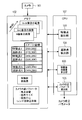
- FIG. 1 is a block diagram illustrating a functional configuration of the camera calibration apparatus according to the first embodiment of the present disclosure.
- the configuration and operation of the camera calibration apparatus according to the present embodiment will be described with reference to FIG.
- the camera calibration device of the present embodiment is installed on a moving body such as a vehicle.
- This camera calibration apparatus calibrates the camera 101, and includes a memory 102, a feature point extraction unit 103, a tracking point extraction unit 104, and a camera calibration parameter calculation unit 105.
- FIG. 1 also shows a vehicle 106.
- Each of the feature point extraction unit 103, the tracking point extraction unit 104, and the camera calibration parameter calculation unit 105 includes a CPU (Central Processing Unit) 107 in a camera calibration device in a ROM (Read Only Memory, not shown). This is realized by executing the stored program. Note that each unit may be realized by a dedicated circuit configured by hardware instead of using the CPU and ROM.
- CPU Central Processing Unit
- ROM Read Only Memory
- the camera 101 is installed in a vehicle and stores in the memory 102 images chronologically captured images of the road surface while the vehicle is moving.
- the feature point extraction unit 103 extracts feature points from the Nth image stored in the memory 102 as shown in FIG. 2 and stores the image coordinates of the feature points in the memory 102.
- the image coordinates are a two-dimensional coordinate system having the origin at the upper left of the image placed on the memory.
- a feature point is a point at which a luminance information amount in a predetermined range including the point has a characteristic size. For example, a Harris corner point or the like is searched for as the feature point.
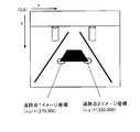
- the tracking point extraction unit 104 extracts a point having the same feature as the feature point from the (N + 1) th image stored in the memory 102 as illustrated in FIG. 3 as a tracking point, and stores the image coordinates of the tracking point in the memory 102. To do.
- the tracking point is extracted using a processing method such as the Kanade-Lucas-Tomasi method (the KLT).
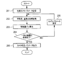
- the camera calibration parameter calculation unit 105 calculates camera calibration parameters. Hereinafter, the process performed by the camera calibration parameter calculation unit 105 will be described in detail with reference to FIG.
- the camera calibration parameter calculation unit 105 sets the camera angle (pan, tilt, roll) and camera position of the camera mounting design value as initial camera parameters.
- the camera calibration parameter calculation unit 105 converts the image coordinates of the feature points and the image coordinates of the tracking points stored in the memory 102 into world coordinates. Details of the processing in step 202 will be described later.
- the camera calibration parameter calculation unit 105 calculates the movement amount of each feature point and tracking point on the world coordinates and the movement amount of the actual moving object stored in the memory 102. Is calculated as a shift in the movement amount. Details of the processing in step 203 will be described later.
- the camera calibration parameter calculation unit 105 changes the camera parameters within a certain range, and repeats the processing of Step 202-203 (Step 204: NO, 205).
- the camera calibration parameter calculation unit 105 uses the displacement of the movement amount as the evaluation value. To do. Then, the camera parameter (camera angle, position) that minimizes the evaluation value is used as a camera calibration parameter indicating the correspondence between the camera image and the actual road, and the camera calibration parameter is a camera image calibration device (not shown). Output to.
- the camera image calibration apparatus appropriately calibrates an image displayed on an in-vehicle monitor (not shown) using camera calibration parameters.
- step 202 feature point and tracking point coordinate conversion processing (step 202), that is, image coordinates of the feature point and tracking point stored in the memory 102 are converted into world coordinates. Details of the processing to be performed will be described.
- the world coordinates are a three-dimensional coordinate system in the real world, and the expressions (1) to (4) are the world coordinates (X W , Y W , Z W ) and the camera coordinates (X C , Y C , Z C ).
- the relationship between world coordinates and camera coordinates is determined by parameters of a rotation matrix R and a parallel progression T.
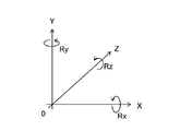
- the X axis, the Y axis, and the Z axis are provided as shown in FIG. 6A.
- FIG. 6A when the X-axis, Y-axis, and Z-axis are each viewed in the positive direction from the origin, the direction of rotating counterclockwise around each axis is defined as the positive direction of rotation.
- Rx represents a rotation angle with respect to the X axis
- Ry represents a rotation angle with respect to the Y axis
- Rz represents a rotation angle with respect to the Z axis.
- the direction turning counterclockwise with respect to the direction from the origin toward the positive direction is set as the positive direction of Rz.
- Rx and Ry are the same applies.
- the camera calibration parameter calculation unit 105 converts the input image coordinates (image x coordinate, image y coordinate) into distorted sensor coordinates (distorted sensor x coordinate, distorted sensor y coordinate).
- Expressions (5) and (6) are expressions showing the relationship between image coordinates and sensor coordinates with distortion. For the pixel pitch and image center in the x and y directions, values stored in the memory 102 as camera internal parameters are used.
- the camera calibration parameter calculation unit 105 converts the sensor coordinates with distortion into sensor coordinates without distortion (sensor x coordinates without distortion, sensor y coordinates without distortion).
- Expressions (7) to (9) are expressions indicating the relationship between the sensor coordinates with distortion and the sensor coordinates without distortion.
- kappa1 is a lens distortion correction coefficient, which is a known value.
- the lens distortion correction coefficient uses a value stored in the memory 102 as an internal camera parameter.
- step 303 the camera calibration parameter calculation unit 105 converts the sensor coordinates without distortion into world coordinates.
- Expressions (10) to (14) are expressions showing the relationship between the sensor coordinates without distortion and the world coordinates.
- Equation (10) can be converted into equation for camera x-coordinate X C.
- Expression (12) can be converted into an expression for obtaining the camera y coordinate Y C.
- the camera calibration parameter calculation unit 105 A three-dimensional equation in Expression (14) is derived from Expression (1), Expression (11), and Expression (13), and the world x coordinate Xw and the world z coordinate Zw can be calculated.
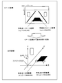
- the image coordinates of each feature point and tracking point are converted into points of world coordinates as shown in FIG.
- the point dropped from the vertex of the optical axis of the camera perpendicular to the road surface is used as the origin, and the image coordinate values shown in FIG. 2 are used as an example.
- the camera calibration parameter calculation unit 105 calculates the movement amount on the world coordinate in the Z-axis direction and the X-axis direction from the feature point and the tracking point converted into the world coordinate by Expression (15).
- the camera calibration parameter calculation unit 105 calculates the difference between the movement amount of each feature point and tracking point in the world coordinates and the movement amount of the actual moving object stored in the memory 102 by the equation (16). Calculated as the amount of deviation.
- the actual amount of movement of the moving body is calculated based on information about the amount of movement acquired from the vehicle 106 (vehicle speed pulse, steering angle information, vehicle speed, etc.) and stored in the memory 102. If there is no deviation in the attachment of the camera, the deviation between the movement amount calculated using the camera parameters and the actual movement amount of the vehicle is “0”.
- the displacement (evaluation value) of the moving amount is
- 30.
- the camera calibration parameter is calculated by calculating the movement amount in the real world using the feature point and the tracking point on the image taken while the vehicle is moving. Therefore, the camera calibration can be automatically performed when the vehicle moves on the production line without stopping the vehicle on the production line.
- FIG. 9 is a block diagram illustrating a functional configuration of the camera calibration apparatus according to the second embodiment of the present disclosure.
- the camera calibration apparatus shown in FIG. 9 employs a configuration in which a moving body movement amount calculation unit 806 is added in the CPU 107, as compared with the camera calibration apparatus shown in FIG.
- the moving body moving amount calculation unit 806 calculates the moving amount of the moving body (vehicle).
- vehicle vehicle
- details of the processing of the moving body movement amount calculation unit 806 will be described with reference to FIG.
- the moving body movement amount calculation unit 806 calculates the relative translation of the camera 101 from the basic matrix F and the focal length f according to Expression (18).
- a matrix T (unit matrix) and a rotation matrix R are calculated.
- Matrix-T ⁇ E is subjected to singular value decomposition as represented by (Equation 19).
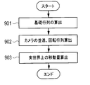
- step 903 the moving body movement calculation unit 806 calculates the movement in the real world from the relative parallel progression T and the rotation matrix R of the camera.
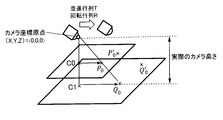
- step 903 will be described in detail with reference to FIG.
- a point (feature point) in the camera camera coordinates before movement is represented by P0
- a point (tracking point) in the vehicle camera coordinates after movement is represented by P'0.
- the relationship between P0 and P′0 is expressed by Expression (21).
- Equation (22) The normal vector of the plane represented by Equation (22) is (a, b, c), and the equation of a straight line orthogonal to this plane is represented by Equation (23).
- the moving body movement amount calculation unit 806 calculates a perpendicular line from the origin of the camera coordinates to the plane, and obtains the coordinates of the intersection C0 according to Expression (24).
- the moving body moving amount calculating unit 806 extends a straight line connecting the camera coordinate origin and C1, and calculates a point C1 equal to the camera height using the formula (Equation 25) of the distance between the point and the plane. That is, the distance D between the plane p0 represented by the equation (22) and the point C0 (x0, y0, z0) is
- the camera can be automatically calibrated when the vehicle moves on the production line without stopping the vehicle on the production line. .
- the invention according to the present disclosure is used in an in-vehicle camera calibration system that calibrates a camera using an image taken by a camera.
Abstract
Provided is a vehicle-mounted camera calibration system which performs camera calibration automatically when a vehicle is moved in a production line without stopping the vehicle on the production line. The vehicle-mounted camera calibration system is provided with: a camera which is attached to the vehicle and which captures an image of a road surface in a time series; a memory in which the image captured by the camera is stored in a time series; a feature point extraction unit which extracts a feature point from the captured image stored in the memory; a tracking point extraction unit which extracts a tracking point to which the feature point moves after the elapse of a predetermined time; and a camera calibration parameter calculation unit which calculates a camera calibration parameter from the feature point and the tracking point.
Description
本開示は、カメラにより撮影された画像を用いてカメラ画像の校正を行う車載カメラ用校正システムに関する。
The present disclosure relates to an in-vehicle camera calibration system that calibrates a camera image using an image captured by a camera.
従来から、車載カメラで撮影された車両後方の画像を車載モニタに表示することで、運転者から死角になる車両後方直近の状況を車載モニタに表示された画像として視認し、車両後退時の視認性を向上させることが行われている。
Conventionally, by displaying an image of the rear of the vehicle captured by the in-vehicle camera on the in-vehicle monitor, the situation immediately behind the vehicle, which is a blind spot from the driver, can be visually recognized as an image displayed on the in-vehicle monitor, and viewed when the vehicle is moving backward It is done to improve the sex.
このような車載カメラの画像を車載モニタに表示するに際しては、車載カメラの車両への取り付け状態を是正するために、車両の後方に校正用のターゲットを設置する。そして、車載モニタに映った校正用ターゲットの像を見ながら、その校正用ターゲットの像が適正に映るように車載カメラの取り付け状態を調整することが行われる。
When displaying such an image of the in-vehicle camera on the in-vehicle monitor, a calibration target is installed behind the vehicle in order to correct the mounting state of the in-vehicle camera on the vehicle. Then, while viewing the image of the calibration target reflected on the vehicle-mounted monitor, the mounting state of the vehicle-mounted camera is adjusted so that the image of the calibration target is appropriately projected.
また、車載カメラで得られた画像に対して、校正用ターゲットの像に基づいた所定の演算処理を施すことで車載モニタに映る画像を適正に校正することが行われている。
In addition, an image displayed on the in-vehicle monitor is appropriately calibrated by applying a predetermined arithmetic processing based on the image of the calibration target to the image obtained by the in-vehicle camera.
また、車両の全周囲を複数の車載カメラで撮影し、各車載カメラで得られた複数の画像をそれぞれ車両の真上から見下ろしたような画像(俯瞰画像)に変換する。それとともに、各画像間での位置を調整したマッピングを行うことで、単一の視点変換合成画像を得ることも行われている。このような場合には、隣接する2つの画像間で精度よく位置合わせを行う必要があるため、高精度の校正が求められる。
Also, the entire periphery of the vehicle is photographed by a plurality of in-vehicle cameras, and the plurality of images obtained by each in-vehicle camera are converted into images (overhead images) that look down from directly above the vehicle. At the same time, a single viewpoint-converted composite image is also obtained by performing mapping with adjusted positions between the images. In such a case, since it is necessary to perform alignment between two adjacent images with high accuracy, high-precision calibration is required.
しかし、従来の校正方法は、校正用ターゲットと車両との相対的な位置関係を厳密に定める必要があった。そのため、車両を設置した後にその車両に対して精度よく校正用ターゲットを設置するか、または校正用ターゲットを設置した後にその校正用ターゲットに対して精度よく車両を設置する必要があった。
However, in the conventional calibration method, it is necessary to strictly determine the relative positional relationship between the calibration target and the vehicle. For this reason, it is necessary to accurately install the calibration target on the vehicle after installing the vehicle, or to install the vehicle on the calibration target with high accuracy after the calibration target is installed.
このため、車両生産ラインでは費用をかけて設備を改造し、車両と校正用ターゲットとの位置合わせ精度を向上させる工夫がされている。さらに、生産現場から一旦出荷された後に販売・サービス会社の整備部門で校正をやり直す場合(修理等の場合や車載カメラ等を後付けする場合等)は、校正用ターゲットをその都度、精度良く設置する必要がある。そのため作業の手間が一層かかるものとなっている。
For this reason, the vehicle production line has been devised to improve the alignment accuracy between the vehicle and the calibration target by modifying the equipment at an expense. In addition, if calibration is performed again in the maintenance department of a sales / service company after being shipped from the production site (for repairs, retrofitting an in-vehicle camera, etc.), the calibration target must be installed accurately each time. There is a need. For this reason, it takes much more work.
このような状況から、車両と校正用ターゲットの相対的な設置精度をさほど要求されない校正方法が望まれており、従来においても幾つかの技術が提案されている。
Under such circumstances, a calibration method that does not require much relative installation accuracy between the vehicle and the calibration target is desired, and several techniques have been proposed in the past.
例えば、特許文献1には、白線格子を校正用ターゲットとし、白線格子の直線度、平行度、直交度、間隔といった、車両の停車状態とは無関係な特徴を利用して、複数台のカメラの内部/歪みパラメータ、および外部パラメータを校正する手法が提案されている。
For example, in Patent Document 1, a white line grid is used as a calibration target, and features that are irrelevant to the stop state of the vehicle, such as linearity, parallelism, orthogonality, and spacing of the white line grid, are used. Techniques have been proposed for calibrating internal / distortion parameters and external parameters.
また、特許文献2には、校正用ターゲットと、校正精度評価用ターゲットが一体化したものを使用して校正する手法が提案されている。
Further, Patent Document 2 proposes a method of calibrating using a calibration target and a calibration accuracy evaluation target integrated.
しかしながら、特許文献1、2は、校正ターゲット内に車両を停車することが必要となっており、工場の生産ラインにおいて、各車両に対して、作業員が車両を校正ターゲット内に停車する作業(コスト)が発生してしまう。
However, in Patent Documents 1 and 2, it is necessary to stop the vehicle in the calibration target. In the factory production line, for each vehicle, an operator stops the vehicle in the calibration target ( Cost).
本開示はかかる点に鑑みてなされたものであり、生産ライン上で車両を停車することなく、車載カメラの校正を行うことができる車載カメラ用校正システムを提供することを目的とする。
The present disclosure has been made in view of such a point, and an object thereof is to provide an in-vehicle camera calibration system that can calibrate an in-vehicle camera without stopping the vehicle on a production line.
本開示の車載カメラ用校正システムは、カメラと、メモリと、特徴点抽出部と、追跡点抽出部と、カメラ校正パラメータ算出部と、を具備する。カメラは、車両に取り付けられ時系列に路面の画像を撮影する。メモリは、カメラで撮影された画像を時系列に保存する。特徴点抽出部は、メモリに保存された撮影画像から特徴点を抽出する。追跡点抽出部は、特徴点の所定時間経過後の移動先である追跡点を抽出する。カメラ校正パラメータ算出部は、特徴点と追跡点からカメラの校正パラメータを算出する。
The in-vehicle camera calibration system according to the present disclosure includes a camera, a memory, a feature point extraction unit, a tracking point extraction unit, and a camera calibration parameter calculation unit. The camera is attached to the vehicle and takes images of the road surface in time series. The memory stores images taken by the camera in time series. The feature point extraction unit extracts feature points from the captured image stored in the memory. The tracking point extraction unit extracts a tracking point that is a destination of the feature point after a predetermined time has elapsed. The camera calibration parameter calculation unit calculates camera calibration parameters from the feature points and tracking points.
本開示によれば、生産ライン上で車両を停車することなく、生産ラインを車両が移動する際に自動的にカメラ校正を行うことができる。従って、車両の位置決めが不要な車載カメラの校正を行うことができる。
According to the present disclosure, it is possible to automatically perform camera calibration when the vehicle moves on the production line without stopping the vehicle on the production line. Therefore, calibration of the in-vehicle camera that does not require positioning of the vehicle can be performed.
(実施の形態1)
以下、本開示の実施の形態について、図面を参照して詳細に説明する。図1は、本開示の実施の形態1に係るカメラ校正装置の機能構成を示すブロック図である。以下、図1を用いて、本実施の形態に係るカメラ校正装置の構成および動作を説明する。 (Embodiment 1)
Hereinafter, embodiments of the present disclosure will be described in detail with reference to the drawings. FIG. 1 is a block diagram illustrating a functional configuration of the camera calibration apparatus according to the first embodiment of the present disclosure. Hereinafter, the configuration and operation of the camera calibration apparatus according to the present embodiment will be described with reference to FIG.
本実施の形態のカメラ校正装置は、車両などの移動体に設置される。このカメラ校正装置は、カメラ101の校正を行うものであって、メモリ102、特徴点抽出部103、追跡点抽出部104およびカメラ校正パラメータ算出部105を備えている。なお、図1には、車両106も示す。
The camera calibration device of the present embodiment is installed on a moving body such as a vehicle. This camera calibration apparatus calibrates the camera 101, and includes a memory 102, a feature point extraction unit 103, a tracking point extraction unit 104, and a camera calibration parameter calculation unit 105. FIG. 1 also shows a vehicle 106.
特徴点抽出部103、追跡点抽出部104およびカメラ校正パラメータ算出部105の各部は、カメラ校正装置内のCPU(中央処理装置、Central Processing Unit)107がROM(Read only Memory、図示せず)に格納されたプログラムを実行することで実現される。なお、CPU、ROMを用いる代わりにハードウェアで構成された専用回路で各部を実現してもよい。
Each of the feature point extraction unit 103, the tracking point extraction unit 104, and the camera calibration parameter calculation unit 105 includes a CPU (Central Processing Unit) 107 in a camera calibration device in a ROM (Read Only Memory, not shown). This is realized by executing the stored program. Note that each unit may be realized by a dedicated circuit configured by hardware instead of using the CPU and ROM.
カメラ101は、車両に設置され、車両の移動中に路面を撮像した画像を時系列的にメモリ102に保存する。
The camera 101 is installed in a vehicle and stores in the memory 102 images chronologically captured images of the road surface while the vehicle is moving.
特徴点抽出部103は、図2に示すようなメモリ102に保存されたN番目の画像から特徴点を抽出し、その特徴点のイメージ座標をメモリ102に保存する。なお、イメージ座標とは、メモリ上に置かれた画像の左上を原点とする2次元の座標系である。また、特徴点とは、その点を含む所定の範囲における輝度の情報量が特徴的な大きさを持つような点である。例えば、ハリスコーナ点等が上記特徴点として探索される。
The feature point extraction unit 103 extracts feature points from the Nth image stored in the memory 102 as shown in FIG. 2 and stores the image coordinates of the feature points in the memory 102. The image coordinates are a two-dimensional coordinate system having the origin at the upper left of the image placed on the memory. A feature point is a point at which a luminance information amount in a predetermined range including the point has a characteristic size. For example, a Harris corner point or the like is searched for as the feature point.
追跡点抽出部104は、図3に示すようなメモリ102に保存されたN+1番目の画像から特徴点と同じ特徴を有する点を追跡点として抽出し、その追跡点のイメージ座標をメモリ102に保存する。追跡点の抽出は、カナデ・ルーカス・トマシ法(the Kanade-Lucas-Tomasi (KLT))などの処理方法を用いて行われる。
The tracking point extraction unit 104 extracts a point having the same feature as the feature point from the (N + 1) th image stored in the memory 102 as illustrated in FIG. 3 as a tracking point, and stores the image coordinates of the tracking point in the memory 102. To do. The tracking point is extracted using a processing method such as the Kanade-Lucas-Tomasi method (the KLT).
カメラ校正パラメータ算出部105は、カメラ校正パラメータを算出する。以下、図4を用いてカメラ校正パラメータ算出部105が行う処理を詳細に説明する。
The camera calibration parameter calculation unit 105 calculates camera calibration parameters. Hereinafter, the process performed by the camera calibration parameter calculation unit 105 will be described in detail with reference to FIG.
まず、初期カメラパラメータ設定処理において(ステップ201)、カメラ校正パラメータ算出部105は、カメラ取り付け設計値のカメラ角度(パン、チルト、ロール)、カメラ位置を初期カメラパラメータと設定する。
First, in the initial camera parameter setting process (step 201), the camera calibration parameter calculation unit 105 sets the camera angle (pan, tilt, roll) and camera position of the camera mounting design value as initial camera parameters.
次に、特徴点、追跡点座標変換処理において(ステップ202)、カメラ校正パラメータ算出部105は、メモリ102に保存された特徴点のイメージ座標と追跡点のイメージ座標を世界座標に変換する。なお、ステップ202の処理の詳細については後述する。
Next, in the feature point / tracking point coordinate conversion process (step 202), the camera calibration parameter calculation unit 105 converts the image coordinates of the feature points and the image coordinates of the tracking points stored in the memory 102 into world coordinates. Details of the processing in step 202 will be described later.
次に、移動量ズレ算出処理において(ステップ203)、カメラ校正パラメータ算出部105は、各特徴点、追跡点の世界座標上の移動量とメモリ102に保存された実際の移動体の移動量との差を、移動量のズレとして算出する。なお、ステップ203の処理の詳細については後述する。
Next, in the movement amount deviation calculation process (step 203), the camera calibration parameter calculation unit 105 calculates the movement amount of each feature point and tracking point on the world coordinates and the movement amount of the actual moving object stored in the memory 102. Is calculated as a shift in the movement amount. Details of the processing in step 203 will be described later.
カメラ校正パラメータ算出部105は、一定の範囲でカメラパラメータを変更し、ステップ202-203の処理を繰り返す(ステップ204:NO、205)。
The camera calibration parameter calculation unit 105 changes the camera parameters within a certain range, and repeats the processing of Step 202-203 (Step 204: NO, 205).
そして、一定の範囲でステップ202-203の処理が完了した後(ステップ204:YES)、カメラ校正パラメータ出力処理において(ステップ206)、カメラ校正パラメータ算出部105は、移動量のズレを評価値とする。そして、この評価値が最少となるカメラパラメータ(カメラ角度、位置)を、カメラの画像と実際の道路との対応関係を示すカメラ校正パラメータとし、カメラ校正パラメータをカメラ画像校正装置(図示せず)に出力する。
Then, after the processing of steps 202-203 is completed within a certain range (step 204: YES), in the camera calibration parameter output processing (step 206), the camera calibration parameter calculation unit 105 uses the displacement of the movement amount as the evaluation value. To do. Then, the camera parameter (camera angle, position) that minimizes the evaluation value is used as a camera calibration parameter indicating the correspondence between the camera image and the actual road, and the camera calibration parameter is a camera image calibration device (not shown). Output to.
なお、カメラ画像校正装置は、カメラ校正パラメータを用いて、車載モニタ(図示せず)に映る画像を適正に校正する。
Note that the camera image calibration apparatus appropriately calibrates an image displayed on an in-vehicle monitor (not shown) using camera calibration parameters.
次に、図5~図7を用いて、特徴点、追跡点座標変換処理(ステップ202)、すなわち、メモリ102に保存された特徴点のイメージ座標と追跡点のイメージ座標を、世界座標に変換する処理の詳細について説明する。
Next, using FIG. 5 to FIG. 7, feature point and tracking point coordinate conversion processing (step 202), that is, image coordinates of the feature point and tracking point stored in the memory 102 are converted into world coordinates. Details of the processing to be performed will be described.
なお、世界座標とは実世界上の3次元座標系のことであり、式(1)~式(4)は世界座標(XW,YW,ZW)とカメラ座標(XC,YC,ZC)の関係を示す式である。世界座標とカメラ座標の関係は、回転行列Rと並進行列Tというパラメータにより決定される。世界座標において、X軸、Y軸およびZ軸は図6Aのように設けられる。図6Aにおいて、X軸、Y軸、Z軸についてそれぞれ原点から正向きにみたときに、各軸のまわりを反時計回りに回る向きを回転の正の方向とする。なお、RxはX軸に対する回転角度を表し、RyはY軸に対する回転角度を表す。また、RzはZ軸に対する回転角度を表す。例えば、Z軸まわりの回転においては、図6Bに示すように、原点から正の方向に向かう方向に対して反時計まわりにまわる方向をRzの正の方向とする。Rx、Ryについても同様とする。
The world coordinates are a three-dimensional coordinate system in the real world, and the expressions (1) to (4) are the world coordinates (X W , Y W , Z W ) and the camera coordinates (X C , Y C , Z C ). The relationship between world coordinates and camera coordinates is determined by parameters of a rotation matrix R and a parallel progression T. In the world coordinates, the X axis, the Y axis, and the Z axis are provided as shown in FIG. 6A. In FIG. 6A, when the X-axis, Y-axis, and Z-axis are each viewed in the positive direction from the origin, the direction of rotating counterclockwise around each axis is defined as the positive direction of rotation. Rx represents a rotation angle with respect to the X axis, and Ry represents a rotation angle with respect to the Y axis. Rz represents a rotation angle with respect to the Z axis. For example, in the rotation around the Z axis, as shown in FIG. 6B, the direction turning counterclockwise with respect to the direction from the origin toward the positive direction is set as the positive direction of Rz. The same applies to Rx and Ry.


ステップ301において、カメラ校正パラメータ算出部105は、入力されたイメージ座標(イメージx座標,イメージy座標)を歪ありセンサー座標(歪ありセンサーx座標,歪ありセンサーy座標)に変換する。式(5)、式(6)は、イメージ座標と歪ありセンサー座標の関係を示す式である。なお、x,y方向の画素ピッチと画像中心は、カメラ内部パラメータとしてメモリ102に保存されている値を用いる。
In step 301, the camera calibration parameter calculation unit 105 converts the input image coordinates (image x coordinate, image y coordinate) into distorted sensor coordinates (distorted sensor x coordinate, distorted sensor y coordinate). Expressions (5) and (6) are expressions showing the relationship between image coordinates and sensor coordinates with distortion. For the pixel pitch and image center in the x and y directions, values stored in the memory 102 as camera internal parameters are used.


ステップ302において、カメラ校正パラメータ算出部105は、歪ありセンサー座標を歪なしセンサー座標(歪なしセンサーx座標,歪なしセンサーy座標)に変換する。式(7)~式(9)は、歪ありセンサー座標と歪なしセンサー座標の関係を示す式である。なお、kappa1はレンズ歪補正係数であり、既知の値である。レンズ歪補正係数は、カメラ内部パラメータとしてメモリ102に保存されている値を用いる。
In step 302, the camera calibration parameter calculation unit 105 converts the sensor coordinates with distortion into sensor coordinates without distortion (sensor x coordinates without distortion, sensor y coordinates without distortion). Expressions (7) to (9) are expressions indicating the relationship between the sensor coordinates with distortion and the sensor coordinates without distortion. Note that kappa1 is a lens distortion correction coefficient, which is a known value. The lens distortion correction coefficient uses a value stored in the memory 102 as an internal camera parameter.


ステップ303において、カメラ校正パラメータ算出部105は、歪なしセンサー座標を世界座標に変換する。式(10)~式(14)は、歪なしセンサー座標と世界座標の関係を示す式である。
In step 303, the camera calibration parameter calculation unit 105 converts the sensor coordinates without distortion into world coordinates. Expressions (10) to (14) are expressions showing the relationship between the sensor coordinates without distortion and the world coordinates.

式(10)は、カメラx座標XCを求める式に変換できる。
Equation (10) can be converted into equation for camera x-coordinate X C.


式(12)は、カメラy座標YCを求める式に変換できる。
Expression (12) can be converted into an expression for obtaining the camera y coordinate Y C.

式(1)の回転行列Rと並進行列Tが既に決定している、および、特徴点、追跡点が路面である(世界y座標Yw=0)という条件によって、カメラ校正パラメータ算出部105は、式(1)、式(11)および式(13)から式(14)にある3次元方程式が導き出され、世界x座標Xw、世界z座標Zwを算出できる。
Under the condition that the rotation matrix R and the parallel progression T in Equation (1) have already been determined, and the feature points and tracking points are road surfaces (world y coordinate Yw = 0), the camera calibration parameter calculation unit 105 A three-dimensional equation in Expression (14) is derived from Expression (1), Expression (11), and Expression (13), and the world x coordinate Xw and the world z coordinate Zw can be calculated.

このように、図5のフローが実行されることにより、各特徴点、追跡点のイメージ座標は、図7に示すように世界座標の点に変換される。なお、図7では、カメラの光軸の頂点から路面に垂直に落とした点を原点としており、図2に示すイメージ座標の値を例として用いている。
Thus, by executing the flow of FIG. 5, the image coordinates of each feature point and tracking point are converted into points of world coordinates as shown in FIG. In FIG. 7, the point dropped from the vertex of the optical axis of the camera perpendicular to the road surface is used as the origin, and the image coordinate values shown in FIG. 2 are used as an example.
次に、図8を用いて、移動量ズレ算出処理(ステップ203)の詳細について説明する。
Next, details of the shift amount calculation process (step 203) will be described with reference to FIG.
カメラ校正パラメータ算出部105は、式(15)により、世界座標に変換された特徴点と追跡点からZ軸方向とX軸方向の世界座標上の移動量を算出する。
The camera calibration parameter calculation unit 105 calculates the movement amount on the world coordinate in the Z-axis direction and the X-axis direction from the feature point and the tracking point converted into the world coordinate by Expression (15).

次に、カメラ校正パラメータ算出部105は、式(16)により、各特徴点、追跡点の世界座標上の移動量とメモリ102に保存された実際の移動体の移動量との差を、移動量のズレとして算出する。この場合、実際の移動体(車両)の移動量は、車両106から取得された移動量に関する情報(車速パルスや舵角情報、車速など)に基づいて計算され、メモリ102に保存される。カメラの取り付けにズレがなければ、カメラパラメータを用いて算出した移動量と実際の車両の移動量とのズレは「0」となる。
Next, the camera calibration parameter calculation unit 105 calculates the difference between the movement amount of each feature point and tracking point in the world coordinates and the movement amount of the actual moving object stored in the memory 102 by the equation (16). Calculated as the amount of deviation. In this case, the actual amount of movement of the moving body (vehicle) is calculated based on information about the amount of movement acquired from the vehicle 106 (vehicle speed pulse, steering angle information, vehicle speed, etc.) and stored in the memory 102. If there is no deviation in the attachment of the camera, the deviation between the movement amount calculated using the camera parameters and the actual movement amount of the vehicle is “0”.

図8の例では、式(15)、式(16)を使用することにより、特徴点1のイメージ座標(x,y)=(250,350)が特徴点1の世界座標(X,Y,Z)=(500,0,650)に変換され、追跡点1のイメージ座標(x,y)=(270,300)が追跡点1の世界座標(X,Y,Z)=(600,0,900)に変換されている。
In the example of FIG. 8, the image coordinates (x, y) = (250,350) of the feature point 1 is the world coordinates (X, Y, Z) of the feature point 1 by using the equations (15) and (16). = (500,0,650) and the image coordinates (x, y) = (270,300) of tracking point 1 are converted to the world coordinates (X, Y, Z) = (600,0,900) of tracking point 1 .
また、図8の例においては、式(15)よりX方向の世界座標上の移動量は、追跡点1のX座標から特徴点1のX座標を減ずればよく、600-500=100となる。同様に、Z方向の世界座標上の移動量は、追跡点1のZ座標から特徴点1のZ座標を減ずることにより得られ、900-650=250となる。
In the example of FIG. 8, the movement amount on the world coordinate in the X direction can be obtained by subtracting the X coordinate of the feature point 1 from the X coordinate of the tracking point 1 from the equation (15), which is 600−500 = 100. Become. Similarly, the movement amount on the world coordinate in the Z direction is obtained by subtracting the Z coordinate of the feature point 1 from the Z coordinate of the tracking point 1 and becomes 900−650 = 250.
また、移動体の移動量が奥行き方向230、横方向90としたとき、式(16)より、移動量のズレ(評価値)は、|(230-250)|+|(90-100)|=30となる。
Further, when the moving amount of the moving body is set to 230 in the depth direction and 90 in the horizontal direction, the displacement (evaluation value) of the moving amount is | (230−250) | + | (90−100) | = 30.
以上説明したように、本実施の形態によれば、車両の移動中に撮影された画像上の特徴点と追跡点を用いて実世界上の移動量を算出することにより、カメラ校正パラメータを算出することができるので、生産ライン上で車両を停車することなく、生産ラインを車両が移動する際に自動的にカメラ校正を行うことができる。
As described above, according to the present embodiment, the camera calibration parameter is calculated by calculating the movement amount in the real world using the feature point and the tracking point on the image taken while the vehicle is moving. Therefore, the camera calibration can be automatically performed when the vehicle moves on the production line without stopping the vehicle on the production line.
(実施の形態2)
本開示は、上述した実施の形態1に限定されず、一部を変更した実施の形態も考えられる。以下、本開示の実施の形態2について、図面を参照して詳細に説明する。 (Embodiment 2)
The present disclosure is not limited to the first embodiment described above, and an embodiment in which a part thereof is changed is also conceivable. Hereinafter, Embodiment 2 of the present disclosure will be described in detail with reference to the drawings.
図9は、本開示の実施の形態2に係るカメラ校正装置の機能構成を示すブロック図である。なお、図9に示すカメラ校正装置において、図1に示したカメラ校正装置と共通する構成部分には図1と同一符号を付してその説明を省略する。図9に示すカメラ校正装置は、図1に示したカメラ校正装置と比較して、CPU107内に移動体移動量算出部806を追加した構成を採る。
FIG. 9 is a block diagram illustrating a functional configuration of the camera calibration apparatus according to the second embodiment of the present disclosure. In the camera calibration apparatus shown in FIG. 9, the same components as those in the camera calibration apparatus shown in FIG. The camera calibration apparatus shown in FIG. 9 employs a configuration in which a moving body movement amount calculation unit 806 is added in the CPU 107, as compared with the camera calibration apparatus shown in FIG.
移動体移動量算出部806は、移動体(車両)の移動量を算出する。以下、図10を用いて、移動体移動量算出部806の処理の詳細を説明する。
The moving body moving amount calculation unit 806 calculates the moving amount of the moving body (vehicle). Hereinafter, the details of the processing of the moving body movement amount calculation unit 806 will be described with reference to FIG.
まず、基礎行列の算出処理において(ステップ901)、移動体移動量算出部806は、対応する特徴点と追跡点のイメージ座標の組(xα,yα), (x’α,y’α),α=1,…,N(≧8)を入力とし、式(17)によりF行列を算出する。
First, in the basic matrix calculation process (step 901), the moving body movement amount calculation unit 806 includes a set of image coordinates of the corresponding feature point and tracking point (xα, yα), (x′α, y′α), .alpha. = 1,..., N (.gtoreq.8) are used as inputs, and the F matrix is calculated by equation (17).

なお、行列F=(Fij)(i=1~3,j=1~3)は基礎行列であり、fは焦点距離である。
Note that the matrix F = (Fij) (i = 1 to 3, j = 1 to 3) is a basic matrix, and f is a focal length.
次に、カメラの並進行列T、回転行列算出処理において(ステップ902)、移動体移動量算出部806は、基礎行列Fと焦点距離fから、式(18)により、カメラ101の相対的な並進行列T(単位行列)と回転行列Rを算出する。
Next, in the translation sequence T and rotation matrix calculation process of the camera (step 902), the moving body movement amount calculation unit 806 calculates the relative translation of the camera 101 from the basic matrix F and the focal length f according to Expression (18). A matrix T (unit matrix) and a rotation matrix R are calculated.

ここで、焦点距離は、内部パラメータとして保持しているため、f0=f=f’である。また、対称行列EETの最小固有値に対する単位固有ベクトルを並進行列Tとする。
Here, since the focal length is held as an internal parameter, f 0 = f = f ′. Also, the unit eigenvector for the smallest eigenvalue of the symmetric matrix EE T and translation matrix T.
行列―T×Eは、(式19)で表すように特異値分解される。
Matrix-T × E is subjected to singular value decomposition as represented by (Equation 19).

また、回転行列Rは、(式20)で表すように計算される。
Also, the rotation matrix R is calculated as represented by (Equation 20).

次に、実世界上の移動量算出処理において(ステップ903)、移動体移動量算出部806は、カメラの相対的な並進行列Tと回転行列Rから実世界上の移動量を算出する。以下、図11を用いて、ステップ903について詳細に説明する。なお、図11において、移動前における車両のカメラ座標での点(特徴点)はP0、移動後における車両のカメラ座標での点(追跡点)はP’0で表される。このとき、P0とP’0との関係は、式(21)で表される。
Next, in the movement calculation process in the real world (step 903), the moving body movement calculation unit 806 calculates the movement in the real world from the relative parallel progression T and the rotation matrix R of the camera. Hereinafter, step 903 will be described in detail with reference to FIG. In FIG. 11, a point (feature point) in the camera camera coordinates before movement is represented by P0, and a point (tracking point) in the vehicle camera coordinates after movement is represented by P'0. At this time, the relationship between P0 and P′0 is expressed by Expression (21).

まず、移動体移動量算出部806は、特徴点のカメラ座標をPi(i=1,2,…,n)から、式(10)、式(11)により、平面の方程式を算出する。なお、特徴点は路面上の点なので、特徴点のカメラ座標Piは、一つの平面上にある。
First, the moving body moving amount calculation unit 806 calculates a plane equation from Pi (i = 1, 2,..., N) of the camera coordinates of the feature points according to equations (10) and (11). Since the feature point is a point on the road surface, the camera coordinates Pi of the feature point are on one plane.

式(22)で表される平面の法線ベクトルは(a,b,c)である、この平面と直交する直線の方程式は、式(23)で表される。
The normal vector of the plane represented by Equation (22) is (a, b, c), and the equation of a straight line orthogonal to this plane is represented by Equation (23).

次に、移動体移動量算出部806は、カメラ座標の原点から平面への垂線を計算し、式(24)により、交点C0の座標を求める。
Next, the moving body movement amount calculation unit 806 calculates a perpendicular line from the origin of the camera coordinates to the plane, and obtains the coordinates of the intersection C0 according to Expression (24).

ただし、Tは単位行列なのでカメラ座標原点と交点C0間の距離は、カメラ高さに等しくない。そこで、移動体移動量算出部806は、カメラ座標原点とC1を結ぶ直線を延長し、カメラ高さに等しい点C1を、点と平面の距離の公式(式25)を用いて算出する。すなわち、式(22)で表される平面p0と、点C0(x0,y0,z0)との距離Dは、
However, since T is a unit matrix, the distance between the camera coordinate origin and the intersection C0 is not equal to the camera height. Therefore, the moving body moving amount calculating unit 806 extends a straight line connecting the camera coordinate origin and C1, and calculates a point C1 equal to the camera height using the formula (Equation 25) of the distance between the point and the plane. That is, the distance D between the plane p0 represented by the equation (22) and the point C0 (x0, y0, z0) is

である。
It is.
図11のC0P0とC1Q0は平行なのでQ0を求めることができる。同様に、Q'0も求めることができる。移動体移動量算出部806は、車両の移動前の点Q0と移動後の点Q'0を求め、すべての特徴点のカメラ座標をPi(i=1,2,…n)での移動ベクトルの平均を求めて実世界上の移動量とし、メモリ102に保存する。
Since C0P0 and C1Q0 in Fig. 11 are parallel, Q0 can be obtained. Similarly, Q′0 can be obtained. The moving body movement amount calculation unit 806 obtains a point Q0 before the movement of the vehicle and a point Q′0 after the movement, and sets the camera coordinates of all feature points as movement vectors at Pi (i = 1, 2,... N). Is obtained as a movement amount in the real world and stored in the memory 102.
以上のように、本実施の形態によっても、実施の形態1と同様に、生産ライン上で車両を停車することなく、生産ラインを車両が移動する際に自動的にカメラ校正を行うことができる。
As described above, according to the present embodiment, as in the first embodiment, the camera can be automatically calibrated when the vehicle moves on the production line without stopping the vehicle on the production line. .
本開示にかかる発明は、カメラにより撮影された画像を用いてカメラの校正を行う車載カメラ用校正システムに用いられる。
The invention according to the present disclosure is used in an in-vehicle camera calibration system that calibrates a camera using an image taken by a camera.
101 カメラ
102 メモリ
103 特徴点抽出部
104 追跡点抽出部
105 カメラ校正パラメータ算出部
106 車両
107 CPU
806 移動体移動量算出部 DESCRIPTION OFSYMBOLS 101 Camera 102 Memory 103 Feature point extraction part 104 Tracking point extraction part 105 Camera calibration parameter calculation part 106 Vehicle 107 CPU
806 Moving body movement amount calculation unit
102 メモリ
103 特徴点抽出部
104 追跡点抽出部
105 カメラ校正パラメータ算出部
106 車両
107 CPU
806 移動体移動量算出部 DESCRIPTION OF
806 Moving body movement amount calculation unit
Claims (9)
- 車両に取り付けられ時系列に路面の画像を撮影するカメラと、
前記カメラで撮影された画像を時系列に保存するメモリと、
前記メモリに保存された撮影画像から特徴点を抽出する特徴点抽出部と、
前記特徴点の所定時間経過後の移動先である追跡点を抽出する追跡点抽出部と、
前記特徴点と前記追跡点から前記カメラの校正パラメータを算出するカメラ校正パラメータ算出部と、
を具備する車載カメラ用校正システム。 A camera attached to the vehicle to shoot images of the road surface in time series;
A memory for storing images taken by the camera in time series;
A feature point extraction unit that extracts feature points from the captured image stored in the memory;
A tracking point extraction unit that extracts a tracking point that is a destination of movement after a predetermined time of the feature point;
A camera calibration parameter calculation unit for calculating a calibration parameter of the camera from the feature point and the tracking point;
A calibration system for in-vehicle cameras. - 前記特徴点抽出部は、CPUがプログラムを実行することにより抽出処理を行う、
請求項1に記載の車載カメラ用校正システム。 The feature point extraction unit performs an extraction process by the CPU executing a program.
The in-vehicle camera calibration system according to claim 1. - 前記追跡点抽出部は、CPUがプログラムを実行することにより抽出処理を行う、
請求項1に記載の車載カメラ用校正システム。 The tracking point extraction unit performs an extraction process by the CPU executing a program.
The in-vehicle camera calibration system according to claim 1. - 前記カメラ校正パラメータ算出部は、CPUがプログラムを実行することにより算出処理を行う、
請求項1に記載の車載カメラ用校正システム。 The camera calibration parameter calculation unit performs a calculation process by the CPU executing a program.
The in-vehicle camera calibration system according to claim 1. - 前記カメラ校正パラメータ算出部は、前記特徴点のイメージ座標と前記追跡点のイメージ座標を世界座標に変換することにより前記カメラの校正パラメータを算出する、
請求項1に記載の車載カメラ用校正システム。 The camera calibration parameter calculation unit calculates calibration parameters of the camera by converting the image coordinates of the feature points and the image coordinates of the tracking points into world coordinates.
The in-vehicle camera calibration system according to claim 1. - 前記車両に関する車速情報と舵角情報を取得し、前記車両の移動量を算出して前記メモリに保存する、
請求項5に記載の車載カメラ用校正システム。 Obtaining vehicle speed information and rudder angle information related to the vehicle, calculating the amount of movement of the vehicle and storing it in the memory;
The in-vehicle camera calibration system according to claim 5. - 前記特徴点抽出部が抽出する特徴点と前記追跡点抽出部が抽出する追跡点から基礎行列を算出し、算出した前記基礎行列から前記車両の移動量を算出する移動体移動量算出部を更に具備する、
請求項5に記載の車載カメラ用校正システム。 A moving body moving amount calculating unit that calculates a basic matrix from the characteristic points extracted by the characteristic point extracting unit and the tracking points extracted by the tracking point extracting unit, and calculates the moving amount of the vehicle from the calculated basic matrix; Have
The in-vehicle camera calibration system according to claim 5. - 前記カメラ校正パラメータ算出部は、前記車両の移動量と前記世界座標から前記カメラの校正パラメータを算出する、
請求項6に記載の車載カメラ用校正システム。 The camera calibration parameter calculation unit calculates a calibration parameter of the camera from a movement amount of the vehicle and the world coordinates.
The in-vehicle camera calibration system according to claim 6. - 前記カメラ校正パラメータ算出部は、前記車両の移動量と前記世界座標から前記カメラの校正パラメータを算出する、
請求項7に記載の車載カメラ用校正システム。 The camera calibration parameter calculation unit calculates a calibration parameter of the camera from a movement amount of the vehicle and the world coordinates.
The in-vehicle camera calibration system according to claim 7.
Priority Applications (1)
| Application Number | Priority Date | Filing Date | Title |
|---|---|---|---|
| US15/997,806 US20180286078A1 (en) | 2016-02-03 | 2018-06-05 | Vehicle-mounted camera calibration system |
Applications Claiming Priority (2)
| Application Number | Priority Date | Filing Date | Title |
|---|---|---|---|
| JP2016-019072 | 2016-02-03 | ||
| JP2016019072A JP2017139612A (en) | 2016-02-03 | 2016-02-03 | On-vehicle camera calibration system |
Related Child Applications (1)
| Application Number | Title | Priority Date | Filing Date |
|---|---|---|---|
| US15/997,806 Continuation US20180286078A1 (en) | 2016-02-03 | 2018-06-05 | Vehicle-mounted camera calibration system |
Publications (1)
| Publication Number | Publication Date |
|---|---|
| WO2017135081A1 true WO2017135081A1 (en) | 2017-08-10 |
Family
ID=59499726
Family Applications (1)
| Application Number | Title | Priority Date | Filing Date |
|---|---|---|---|
| PCT/JP2017/002092 WO2017135081A1 (en) | 2016-02-03 | 2017-01-23 | Vehicle-mounted camera calibration system |
Country Status (3)
| Country | Link |
|---|---|
| US (1) | US20180286078A1 (en) |
| JP (1) | JP2017139612A (en) |
| WO (1) | WO2017135081A1 (en) |
Cited By (3)
| Publication number | Priority date | Publication date | Assignee | Title |
|---|---|---|---|---|
| WO2020129286A1 (en) * | 2018-12-19 | 2020-06-25 | クラリオン株式会社 | Calibration device and calibration method |
| CN113120080A (en) * | 2021-04-12 | 2021-07-16 | 沈阳中科创达软件有限公司 | Method and device for establishing backing auxiliary line, terminal and storage medium |
| CN114347917A (en) * | 2021-12-28 | 2022-04-15 | 华人运通(江苏)技术有限公司 | Vehicle and vehicle-mounted camera system calibration method and device |
Families Citing this family (18)
| Publication number | Priority date | Publication date | Assignee | Title |
|---|---|---|---|---|
| US10504241B2 (en) * | 2016-12-19 | 2019-12-10 | Magna Electronics Inc. | Vehicle camera calibration system |
| US10435173B2 (en) * | 2017-01-16 | 2019-10-08 | The Boeing Company | Remote optical control surface indication system |
| JP6846640B2 (en) * | 2017-09-15 | 2021-03-24 | パナソニックIpマネジメント株式会社 | On-board camera calibration device |
| JP2019061510A (en) * | 2017-09-27 | 2019-04-18 | 国立研究開発法人農業・食品産業技術総合研究機構 | Mounting height parameter calculation device for car-mounted camera and mounting height parameter calculation method therefor |
| JP6890293B2 (en) * | 2017-11-06 | 2021-06-18 | パナソニックIpマネジメント株式会社 | Camera calibration device, camera calibration system, camera calibration method and program |
| CN108769576B (en) * | 2018-05-10 | 2021-02-02 | 郑州信大先进技术研究院 | Intelligent video processing method and system |
| CN109859278B (en) * | 2019-01-24 | 2023-09-01 | 惠州市德赛西威汽车电子股份有限公司 | Calibration method and calibration system for camera external parameters of vehicle-mounted camera system |
| CN111508027B (en) * | 2019-01-31 | 2023-10-20 | 杭州海康威视数字技术股份有限公司 | Method and device for calibrating external parameters of camera |
| JP7169227B2 (en) * | 2019-02-28 | 2022-11-10 | 株式会社デンソーテン | Anomaly detection device and anomaly detection method |
| JP7217577B2 (en) * | 2019-03-20 | 2023-02-03 | フォルシアクラリオン・エレクトロニクス株式会社 | CALIBRATION DEVICE, CALIBRATION METHOD |
| CN112132902B (en) * | 2019-06-24 | 2024-01-16 | 上海安亭地平线智能交通技术有限公司 | Vehicle-mounted camera external parameter adjusting method and device, electronic equipment and medium |
| JP7237773B2 (en) * | 2019-08-23 | 2023-03-13 | 株式会社デンソーテン | Posture estimation device, anomaly detection device, correction device, and posture estimation method |
| CN110619664B (en) * | 2019-09-17 | 2023-06-27 | 武汉理工大学 | Laser pattern-assisted camera distance posture calculation method and server |
| CN110827358B (en) * | 2019-10-15 | 2023-10-31 | 深圳数翔科技有限公司 | Camera calibration method applied to automatic driving automobile |
| CN111223150A (en) * | 2020-01-15 | 2020-06-02 | 电子科技大学 | Vehicle-mounted camera external parameter calibration method based on double vanishing points |
| KR20220026422A (en) * | 2020-08-25 | 2022-03-04 | 삼성전자주식회사 | Apparatus and method for calibrating camera |
| CN112562014A (en) * | 2020-12-29 | 2021-03-26 | 纵目科技(上海)股份有限公司 | Camera calibration method, system, medium and device |
| CN117597705A (en) * | 2022-06-13 | 2024-02-23 | 北京小米移动软件有限公司 | Camera calibration method and device and readable storage medium |
Citations (5)
| Publication number | Priority date | Publication date | Assignee | Title |
|---|---|---|---|---|
| JP2007256029A (en) * | 2006-03-23 | 2007-10-04 | Denso It Laboratory Inc | Stereo image processing device |
| JP2007263669A (en) * | 2006-03-28 | 2007-10-11 | Denso It Laboratory Inc | Three-dimensional coordinates acquisition system |
| JP2011217233A (en) * | 2010-04-01 | 2011-10-27 | Alpine Electronics Inc | On-vehicle camera calibration system, and computer program |
| JP2014048803A (en) * | 2012-08-30 | 2014-03-17 | Denso Corp | Image processor, and program |
| JP2014165810A (en) * | 2013-02-27 | 2014-09-08 | Fujitsu Ten Ltd | Parameter acquisition device, parameter acquisition method and program |
Family Cites Families (3)
| Publication number | Priority date | Publication date | Assignee | Title |
|---|---|---|---|---|
| JP2009017462A (en) * | 2007-07-09 | 2009-01-22 | Sanyo Electric Co Ltd | Driving support system and vehicle |
| JP4831374B2 (en) * | 2009-03-27 | 2011-12-07 | アイシン・エィ・ダブリュ株式会社 | Driving support device, driving support method, and driving support program |
| JP6107081B2 (en) * | 2012-11-21 | 2017-04-05 | 富士通株式会社 | Image processing apparatus, image processing method, and program |
-
2016
- 2016-02-03 JP JP2016019072A patent/JP2017139612A/en active Pending
-
2017
- 2017-01-23 WO PCT/JP2017/002092 patent/WO2017135081A1/en active Application Filing
-
2018
- 2018-06-05 US US15/997,806 patent/US20180286078A1/en not_active Abandoned
Patent Citations (5)
| Publication number | Priority date | Publication date | Assignee | Title |
|---|---|---|---|---|
| JP2007256029A (en) * | 2006-03-23 | 2007-10-04 | Denso It Laboratory Inc | Stereo image processing device |
| JP2007263669A (en) * | 2006-03-28 | 2007-10-11 | Denso It Laboratory Inc | Three-dimensional coordinates acquisition system |
| JP2011217233A (en) * | 2010-04-01 | 2011-10-27 | Alpine Electronics Inc | On-vehicle camera calibration system, and computer program |
| JP2014048803A (en) * | 2012-08-30 | 2014-03-17 | Denso Corp | Image processor, and program |
| JP2014165810A (en) * | 2013-02-27 | 2014-09-08 | Fujitsu Ten Ltd | Parameter acquisition device, parameter acquisition method and program |
Cited By (6)
| Publication number | Priority date | Publication date | Assignee | Title |
|---|---|---|---|---|
| WO2020129286A1 (en) * | 2018-12-19 | 2020-06-25 | クラリオン株式会社 | Calibration device and calibration method |
| JP2020098550A (en) * | 2018-12-19 | 2020-06-25 | クラリオン株式会社 | Calibration device, and calibration method |
| JP7191671B2 (en) | 2018-12-19 | 2022-12-19 | フォルシアクラリオン・エレクトロニクス株式会社 | CALIBRATION DEVICE, CALIBRATION METHOD |
| CN113120080A (en) * | 2021-04-12 | 2021-07-16 | 沈阳中科创达软件有限公司 | Method and device for establishing backing auxiliary line, terminal and storage medium |
| CN114347917A (en) * | 2021-12-28 | 2022-04-15 | 华人运通(江苏)技术有限公司 | Vehicle and vehicle-mounted camera system calibration method and device |
| CN114347917B (en) * | 2021-12-28 | 2023-11-10 | 华人运通(江苏)技术有限公司 | Calibration method and device for vehicle and vehicle-mounted camera system |
Also Published As
| Publication number | Publication date |
|---|---|
| JP2017139612A (en) | 2017-08-10 |
| US20180286078A1 (en) | 2018-10-04 |
Similar Documents
| Publication | Publication Date | Title |
|---|---|---|
| WO2017135081A1 (en) | Vehicle-mounted camera calibration system | |
| JP6154905B2 (en) | Camera calibration apparatus, camera calibration system, and camera calibration method | |
| US8452568B2 (en) | Method for calibrating cameras installed on vehicle | |
| KR20120126016A (en) | The surroundview system camera automatic calibration-only extrinsic parameters | |
| JP6260891B2 (en) | Image processing apparatus and image processing method | |
| WO2015198930A1 (en) | Distance measurement device, and distance measurement correction device using correction parameter | |
| JP5811327B2 (en) | Camera calibration device | |
| JP4857143B2 (en) | Camera posture calculation target device, camera posture calculation method using the same, and image display method | |
| JP2009042162A (en) | Calibration device and method therefor | |
| KR101583663B1 (en) | Method for generating calibration indicator of camera for vehicle | |
| CN112967344B (en) | Method, device, storage medium and program product for calibrating camera external parameters | |
| JP5228614B2 (en) | Parameter calculation apparatus, parameter calculation system and program | |
| JP5959311B2 (en) | Data deriving apparatus and data deriving method | |
| JP5173551B2 (en) | Vehicle perimeter monitoring apparatus and camera mounting position / posture information setting correction method applied thereto | |
| KR101245529B1 (en) | Camera calibration method | |
| JP2007533963A (en) | Non-contact optical measuring method and measuring apparatus for 3D position of object | |
| JP2013024712A (en) | Method and system for calibrating multiple camera | |
| JP7308227B2 (en) | Image processing device, image processing method, and program | |
| TWI424259B (en) | Camera calibration method | |
| JP2016017913A (en) | Posture information preparation system, posture information preparation method, and posture information preparation program | |
| US11403770B2 (en) | Road surface area detection device | |
| CN114993266B (en) | Positioning device and positioning system | |
| CN115880369A (en) | Device, system and method for jointly calibrating line structured light 3D camera and line array camera | |
| JP6890293B2 (en) | Camera calibration device, camera calibration system, camera calibration method and program | |
| WO2013154085A1 (en) | Calibration method and device |
Legal Events
| Date | Code | Title | Description |
|---|---|---|---|
| 121 | Ep: the epo has been informed by wipo that ep was designated in this application |
Ref document number: 17747240 Country of ref document: EP Kind code of ref document: A1 |
|
| NENP | Non-entry into the national phase |
Ref country code: DE |
|
| 122 | Ep: pct application non-entry in european phase |
Ref document number: 17747240 Country of ref document: EP Kind code of ref document: A1 |