WO2017133255A1 - 一种瓷瓶绝缘子架空导线固定装置 - Google Patents
一种瓷瓶绝缘子架空导线固定装置 Download PDFInfo
- Publication number
- WO2017133255A1 WO2017133255A1 PCT/CN2016/099340 CN2016099340W WO2017133255A1 WO 2017133255 A1 WO2017133255 A1 WO 2017133255A1 CN 2016099340 W CN2016099340 W CN 2016099340W WO 2017133255 A1 WO2017133255 A1 WO 2017133255A1
- Authority
- WO
- WIPO (PCT)
- Prior art keywords
- stabilizer
- rod
- wire
- hole
- carrier body
- Prior art date
- Legal status (The legal status is an assumption and is not a legal conclusion. Google has not performed a legal analysis and makes no representation as to the accuracy of the status listed.)
- Ceased
Links
Images


Classifications
-
- H—ELECTRICITY
- H02—GENERATION; CONVERSION OR DISTRIBUTION OF ELECTRIC POWER
- H02G—INSTALLATION OF ELECTRIC CABLES OR LINES, OR OF COMBINED OPTICAL AND ELECTRIC CABLES OR LINES
- H02G7/00—Overhead installations of electric lines or cables
- H02G7/05—Suspension arrangements or devices for electric cables or lines
Definitions
- the invention belongs to the field of electric power equipment, and particularly relates to a porcelain wire insulator overhead wire fixing device.
- the method of fixing the wire between the overhead distribution line and the porcelain insulator is generally performed by the operator using a wire for manual tying, but the manual tying is greatly affected by human factors, and the tying method is not durable. Under the action of natural conditions such as wind, rain and snow, it is easy to loosen or even break the wire, which causes great safety hazards.
- the Chinese utility model patent CN 204741244U discloses a needle-type porcelain insulator insulator overhead wire fixing clip, which comprises a left clamping body and a right clamping body, and the left clamping body and the right clamping body are respectively provided with a curved card matched with the needle-type porcelain bottle insulator.
- the connecting portion, the left clamping body and the right clamping body are respectively provided with fixing holes at both ends, and further comprise two pairs of curved clamping plates, the two pairs of curved clamping plates are provided with fixing holes at both ends, and the two pairs of curved clamping plates are bolted
- the left clamp body, the right clamp body and the overhead conductor are clamped.
- the pin-type porcelain insulator overhead wire fixing clip can solve the problem of manual binding using a wire, however, since the pin-type porcelain insulator overhead wire fixing clip includes a plurality of separate components, and is used for the overhead wire When fixing with the porcelain insulator, it is necessary to use a plurality of bolts and nuts for fixing. Since this operation must be performed at a high altitude, it is difficult for a person to operate independently.
- the present invention provides a porcelain bottle insulator overhead wire fixing device.
- the invention provides a porcelain bottle insulator overhead wire fixing device, comprising a left clamping body and a right clamping body, wherein
- the left collet has a semi-circular left snap portion, a left stabilizer frame and a left wire carrier body, wherein:
- the left snap portion is adapted to the neck of the porcelain insulator
- the left stabilizer frame includes a left stabilizer upper rod, a left stable lower rod, and a left stable middle rod, a left stabilizer intermediate rod connects one end of the left stabilizer upper rod and one end of the left stabilizer lower rod, such that the left stabilizer upper rod, the left stabilizer lower rod, and the left stabilizer
- the middle rod forms a "U" shaped structure
- the left stabilizer upper rod and the left stabilizer lower rod are respectively fixedly connected to both ends of the left fastening portion;
- the upper surface of the left wire carrier body has a left wire carrier body groove matched with the wire, the upper portion of the left wire carrier body is connected with the left wire pressing plate; the middle portion of the left wire pressing plate has a left matching wire a wire pressing plate groove; the left wire carrier body groove and the left wire pressing plate groove forming a structure for accommodating and fixing the wire;
- the right collet has a semi-circular right snap portion, a right stabilizer frame and a right wire carrier body, wherein:
- the right snap portion is adapted to the neck of the porcelain insulator and cooperates with the left snap portion to form an annular structure that is engaged with the neck of the porcelain insulator, thereby clamping and fixing the porcelain insulator overhead wire fixing device On the porcelain insulator;
- the right stabilizer frame includes a right stabilizer upper rod, a right stabilizer lower rod and a right stabilizer middle rod, and the right stabilizer middle rod connects one end of the right stabilizer upper rod and the right stabilizer lower rod One end is connected such that the right stabilizer upper rod, the right stabilizer lower rod and the right stabilizer middle rod form a "U"-shaped structure;
- the right stabilizer upper rod and the right stabilizer lower rod are respectively fixedly connected to both ends of the right snap portion;
- the upper surface of the right wire holder has a right wire carrier groove matching the wire, the upper portion of the right wire carrier is connected to the right wire platen; and the middle portion of the right wire plate has a right wire matching the wire a wire clamping plate groove; the right wire carrier body groove and the right wire plate pressing groove form a structure for accommodating and fixing the wire;
- the left stabilizer upper rod and the right stabilizer upper rod, and the left stabilizer lower rod and the right stabilizer lower rod are connected by means of snapping or bolting, thereby the left clip
- the body and the right body are connected.
- the left stabilizer upper rod and the left stabilizer lower rod are equal in length and parallel to each other; the left stabilizer middle rod is perpendicular to the left stabilizer upper rod and the left stable lower rod ;
- the right stabilizer upper rod and the right stabilizer lower rod are equal in length and parallel to each other; the right stabilizer intermediate rod is perpendicular to the right stabilizer upper rod and the right stable lower rod.
- the left stabilizer middle rod Providing at least one left reinforcing rod between the left locking portion, thereby connecting the left stable frame and the left locking portion more stably;
- At least one right reinforcing rod is disposed between the right snap portions to connect the right stabilizer frame and the right card joint portion more stably.
- the left stabilizer frame and the left card joint portion are in an integrated structure; the right stabilizer frame and the right card joint portion are in an integrated structure.
- an upper portion of the left wire carrier body is connected to the left wire pressing plate by bolts, and the bolts are fixedly connected to two sides of the left wire carrier body groove on the left wire carrier body, and the left wire pressing plate is concave. Both sides of the groove have holes corresponding to the bolts;
- the upper portion of the right wire holder body is connected to the right wire pressing plate by bolts, and the bolts are fixedly connected to the right side of the right wire carrier body groove on the right wire carrier body, and the two right wire plate groove grooves are The side has a hole corresponding to the bolt.
- the lower portion of the left wire carrier and the rod in the stabilizer frame are movably connected, such that the left wire carrier can slide freely on the rod of the left stabilizer;
- the lower portion of the right wire holder and the rod in the stabilizer frame are movably connected such that the right wire holder is free to slide on the rod of the right stabilizer.
- a lower portion of the left wire holder body is provided with a through hole, and a rod of the left stabilizer frame is inserted into the through hole of a lower portion of the wire carrier body, thereby stabilizing the left wire carrier body and the left side
- the brackets are connected and the left wire carrier is free to slide on the rod of the left stabilizer;
- the lower portion of the right wire carrier body is provided with a through hole, and the rod of the right stabilizer frame is inserted into the through hole of the lower portion of the wire carrier body, thereby connecting the right wire carrier body and the right stabilizer frame And causing the right wire holder to slide freely on the rod in the right stabilizer.
- the through hole of the lower portion of the left wire carrier body is a triangular hole or a polygonal hole, and a cross section of the rod in the left stabilizer frame corresponds to the through hole of the lower portion of the left wire carrier body Triangle or polygon;
- the through hole of the lower portion of the right wire carrier body is a triangular hole or a polygonal hole, and the right is stable
- the cross section of the rod in the rack is a triangle or a polygon corresponding to the through hole of the lower portion of the right wire holder;
- the polygonal hole is a quadrangular hole, a pentagonal hole, a hexagonal hole or an octagonal hole; the polygon is a quadrangle, a pentagon, a hexagon or an eight side corresponding to the polygonal hole shape.
- connection manner between the left stabilizer upper rod and the right stabilizer upper rod, and the left stabilizer lower rod and the right stabilizer lower rod is achieved by a snap member;
- the engaging member includes a snap groove and a card joint; wherein the end of the snap groove has a "V" shaped opening, and the "V" shaped opening is formed by two upper walls respectively and the snap groove
- the lower wall is fixedly connected to the elastic piece;
- the card joint has an arrow-shaped plug corresponding to the "V” shaped opening; and the inside of the engaging groove communicating with the "V" shaped opening has the a cavity of the arrow-shaped plug; the arrow-shaped plug is pressed into the cavity of the snap-fit groove through the "V" shaped opening.
- the bolted connection between the left stabilizer upper rod and the right stabilizer upper rod, and between the left stabilizer lower rod and the right stabilizer lower rod is achieved by the following structure:
- the end portions of the left stabilizer upper rod and the right stabilizer upper rod are fixedly connected with a connecting seat;
- the connecting seat has a through hole disposed along a length direction of the upper stabilizer upper rod.
- the through-holes of the left stabilizer stabilizing rod and the connecting seat on the upper stabilizer stud are correspondingly disposed, and the bolt passes through the corresponding through-hole, and the nut is screwed on the bolt, thereby achieving the left stability.
- the end portions of the left stabilizer lower rod and the right stabilizer lower rod are fixedly connected with a connecting seat; the connecting seat has a through hole disposed along a length direction of the left stabilizer lower rod.
- the through hole of the left stabilizer stabilizing rod and the connecting seat on the lower stabilizer lower rod is correspondingly disposed, the bolt passes through the corresponding through hole, and the nut is screwed on the bolt, thereby realizing the left stability
- At least one of the corresponding ends of the left snap portion and the right snap portion has a predetermined position device
- the predetermined position device includes a predetermined position hole and a predetermined position bar, and the predetermined position bar Engaging the left latching portion and the right latching portion into the predetermined hole to achieve a predetermined position of the left clip body and the right clip body on the porcelain insulator;
- the predetermined position hole is a hole at an end of the left engaging portion and open at one end, the predetermined position hole is cylindrical near the top of the open end, the bottom is spherical or ellipsoidal, and the center of the ball is located The top of the column and the bottom of the spherical or ellipsoid intersect at the spherical or ellipsoid a side of the bottom of the shape; the predetermined position bar is a rod-like structure located at an end of the right snap portion and protruding an end of the right snap portion, the predetermined position bar being adjacent to the right snap One end of the portion is a cylinder matching the top of the cylindrical shape of the predetermined hole, and one end away from the right engaging portion is an elastic material matching the spherical or ellipsoidal bottom of the predetermined hole. A sphere or ellipsoid made.
- the porcelain bottle insulator overhead wire fixing device provided by the invention has compact structure, requires few parts to be operated at high altitude, and greatly reduces the types and quantities of parts that the operator needs to carry at high altitude operation, especially the types of scattered small parts and The quantity, therefore, reduces the inconvenience of scattered small parts during high-altitude operation and the drawbacks of easy to fall; at the same time, when operating at high altitude, the overhead wires can be fixed to the porcelain insulators with a very simple operation, which greatly reduces the operator.
- the workload has increased the efficiency of the work.
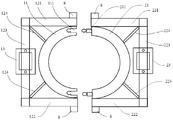
- FIG. 1 is a schematic structural view of a porcelain insulator overhead wire fixing device according to an embodiment of the present invention.
- FIG. 2 is a schematic structural view of a left wire holder body and a left wire platen of a porcelain bottle insulator overhead wire fixing device according to an embodiment of the present invention.
- FIG. 3 is a schematic structural view of a right wire holder body and a right wire platen of a porcelain bottle insulator overhead wire fixing device according to an embodiment of the present invention.
- FIG. 4 is a schematic structural view of a clip of a porcelain insulator overhead wire fixing device according to an embodiment of the present invention.
- FIG. 5 is a schematic structural view of a porcelain insulator overhead wire fixing device according to another embodiment of the present invention.
- a preferred embodiment of the present invention provides a porcelain bottle insulator overhead wire fixing device, comprising a left body and a right body, wherein:
- the left body has a semi-circular left snap portion 11, a left stabilizer frame and a left wire carrier body 13. among them:
- the left snap portion 11 is adapted to the neck of the porcelain insulator and cooperates with the right snap portion 21 to form an annular structure that can be engaged to the neck of the porcelain insulator, thereby clamping and fixing the porcelain insulator overhead wire fixing device to Porcelain bottle insulators.
- the left stabilizer frame includes a left stabilizer upper rod 121, a left stabilizer lower rod 122 and a left stabilizer middle rod 123; wherein the left stabilizer middle rod 123 will have one end of the left stabilizer upper rod 121 and the left stabilizer lower rod 122 One end is connected such that the left stabilizer upper rod 121, the left stabilizer lower rod 122, and the left stabilizer intermediate rod 123 form a "U" shaped structure.
- the left stabilizer upper rod 121 and the left stabilizer lower rod 122 are equal in length and parallel to each other, and the left stabilizer intermediate rod 123 is left stable. Both the upper mast 121 and the left stabilizer lower rail 122 are perpendicular.
- the left stabilizer upper rail 121 and the left stabilizer lower rail 122 are fixedly coupled to both ends of the left engaging portion 11, respectively.
- At least one left reinforcing rod 124 is disposed between the middle and/or left stabilizer intermediate rod 123 and the left engaging portion 11, thereby more stably connecting the left stabilizer and the left locking portion 11; in a preferred implementation
- there are two left reinforcing rods 124 one end of which is connected to the intersection of the left stabilizer upper rod 121 and the left stabilizer middle rod 123, and the other end is connected with the left clamping portion 11, the structure
- the form can not only increase the connection stability of the left stabilizer frame and the left card joint portion 11, but also reduce the material used, so that the left body The structure is lighter, saves costs, and is convenient for
- the upper surface of the left wire holder 13 has a left wire holder groove 131 matching the wire, and the upper portion of the left wire holder 13 is connected to the left wire pressing plate 14, for example, by bolts 5.
- the middle portion of the left wire pressing plate 14 has a left wire platen groove 141 matched with the wire, such that the left wire carrier body groove 131 on the upper surface of the left wire carrier body 13 and the left wire platen groove 141 in the middle of the left wire pressing plate 14 It is possible to form a structure for accommodating and fixing the wires.
- the bolts 5 are fixedly connected (for example, welded) on both sides of the left wire carrier body groove 131 on the left wire carrier body 13, and the left wire platen grooves 141 on the left wire platen 14 have opposite sides.
- the bolts 5 correspond to the holes 6 provided, so that the holes 6 on both sides of the left wire platen groove 141 of the left wire pressing plate 14 can be respectively passed through the left side of the left wire carrier body groove 131 on the left wire carrier body 13.
- the bolts 5 are then screwed together by nuts to secure the wires to the left wire carrier body 13.
- any one of the holes 6 on the left wire pressing plate 14 may be put on the corresponding bolt 5 on the left wire carrier body 13 in advance, and then the nut is screwed to the top end of the bolt 5 (note that the screwing is not too tight)
- the left wire pressing plate 14 should be freely rotatable relative to the left wire carrier body 13, and another hole 6 in the left wire pressing plate 14 can be placed on the other bolt 5 on the left wire carrier body 13; for convenience of operation,
- the length of the other bolt 5 described herein can be set to be slightly shorter than the bolt that has been fitted over the left wire clamp 14).
- the left wire pressing plate 14 can be rotated around the bolt 5, so that the opening of the left wire carrier body groove 131 on the left wire carrier body 13 is opened, and then the wire is opened. Put it into the left wire holder body groove 131, and then rotate the left wire pressing plate 14 around the bolt 5, and insert another hole 6 on the left wire pressing plate 14 into the other bolt 5 on the left wire carrier body 13, and then The nut is screwed onto the bolt 5, and the two nuts are tightened to securely fix the wire to the porcelain insulator overhead wire fixing device.
- This type of structure and operation can reduce the number and number of small parts that are scattered during high-altitude operation, thereby greatly reducing the types and number of parts that operators need to carry, and reducing the inconvenience of scattered small parts during high-altitude operations.
- the lower portion of the left wire holder 13 is connected to the rod 123 in the left stabilizer.
- the lower portion of the left conductor body 13 and the left stabilizer bracket rod 123 are movably coupled such that the left conductor body 13 is free to slide on the left stabilizer intermediate rod 123.
- the left wire holder 13 The lower portion is provided with a through hole 7 so that the left wire holder body 13 and the left stabilizer frame can be connected by inserting the left stabilizer frame middle rod 123 into the through hole 7 in the lower portion of the wire carrier body 13, and the left wire carrier body can be connected.
- the through hole 7 of the lower portion of the left wire holder 13 is a triangular hole or a polygonal hole, including but not limited to a quadrangular hole, a pentagonal hole, a hexagonal hole and an octagonal hole; correspondingly, the left is stable
- the cross section of the center pole 123 is a triangle or a polygon corresponding to the through hole 7 of the lower portion of the left conductor body 13, including but not limited to a quadrangle, a pentagon, a hexagon, and an octagon; that is, for example,
- the cross section of the rod 123 in the left stabilizer frame is substantially the same as the size of the quadrilateral hole (same or slightly smaller than the size of the quadrilateral hole, so that the left wire carrier body 13 can be inserted into the left stabilizer frame middle rod 123 and can slide freely along the left stabilizer middle rod 123, but can
- the right collet has a semi-circular right snap portion 21, a right stabilizer frame and a right wire holder body 23. among them:
- the right snap portion 21 is adapted to the neck of the porcelain insulator and cooperates with the left snap portion 11 to form an annular structure that can be engaged with the neck of the porcelain insulator, thereby clamping and fixing the porcelain insulator overhead wire fixing device to Porcelain bottle insulators.
- the right stabilizer frame includes a right stabilizer upper rod 221, a right stabilizer lower rod 222 and a right stabilizer middle rod 223; wherein the right stabilizer middle rod 223 connects one end of the right stabilizer upper rod 221 and the right stabilizer lower rod 222 One end is connected such that the right stabilizer upper rod 221, the right stabilizer lower rod 222, and the right stabilizer intermediate rod 223 form a "U" shaped structure.
- the right stabilizer upper rod 221 and the right stabilizer lower rod 222 are equal in length and parallel to each other, and the right stabilizer intermediate rod 223 is stable to the right.
- Rack 221 and right The stabilizer lower rods 222 are all vertical.
- the right stabilizer upper rod 221 and the right stabilizer lower rod 222 are fixedly coupled to both ends of the right catching portion 21, respectively.
- At least one right reinforcing rod 224 is disposed between the middle and/or right stabilizer intermediate rod 223 and the right engaging portion 21, thereby connecting the right stabilizer frame and the right locking portion 21 more stably; in a preferred implementation
- there are two right reinforcing rods 224 one end of which is connected to the intersection of the right stabilizer upper rod 221 and the right stabilizer middle rod 223, and the other end is connected with the right clamping portion 21, this structure
- the form can not only increase the connection stability of the right stabilizer frame and the right card joint portion 21, but also reduce the material used, so that the structure of the right body is lighter, which saves cost and facilitates
- the upper surface of the right wire holder body 23 has a right wire holder body groove 231 matched with the wire, and the upper portion of the right wire holder body 23 is connected to the right wire platen 24, for example, by bolts 5.
- the middle portion of the right wire pressing plate 24 has a right wire pressing plate groove 241 matching the wire, such that the right wire carrier body groove 231 on the upper surface of the right wire carrier body 23 and the right wire plate pressing groove 241 in the middle of the right wire pressing plate 24 It is possible to form a structure for accommodating and fixing the wires.
- the bolts 5 are fixedly connected (for example, welded) on both sides of the right wire carrier body groove 231 on the right wire carrier body 23, and the right wire platen groove 241 on both sides of the right wire platen plate 241 has
- the bolts 5 correspond to the holes 6 provided, so that the holes 6 on both sides of the right wire platen groove 241 of the right wire pressing plate 24 can be respectively passed through the right side of the right wire carrier body 231 on the right wire carrier body 23.
- the bolts 5 are then screwed together by nuts to secure the wires to the right wire carrier body 23.
- any one of the holes 6 on the right wire pressing plate 24 may be put on the corresponding bolt 5 on the right wire carrier body 23 in advance, and then the nut is screwed to the top end of the bolt 5 (note that the screwing is not too tight)
- the right wire clamping plate 24 should be freely rotatable relative to the right wire carrier body 23, and another hole 6 in the right wire clamping plate 24 can be placed over the other bolt 5 on the right wire carrier body 23; for ease of operation,
- the length of the other bolt 5 described herein can be set to be slightly shorter than the bolt that has been fitted over the right wire clamp 24).
- the right wire pressing plate 24 can be rotated around the bolt 5, so that the opening of the right wire carrier body groove 231 on the right wire carrier body 23 is opened, and then the wire is opened. Put into the right wire holder body groove 231, and then the right wire platen 24 around the bolt 5 Rotate, put another hole 6 on the right wire clamp 24 into the other bolt 5 on the right wire carrier body 23, then screw the nut onto the bolt 5, and tighten the two nuts to fix the wire stably.
- Porcelain bottle insulators are overhead wire fixing devices.
- This type of structure and operation can reduce the number and number of small parts that are scattered during high-altitude operation, thereby greatly reducing the types and number of parts that operators need to carry, and reducing the inconvenience of scattered small parts during high-altitude operations.
- the lower portion of the right wire holder 23 is connected to the rod 223 of the right stabilizer.
- the lower portion of the right wire holder body 23 and the right stabilizer frame rod 223 are movably coupled such that the right wire carrier body 23 is free to slide on the right stabilizer frame intermediate rod 223.
- the lower portion of the right wire holder body 23 is provided with a through hole 7, so that the right wire holder body 23 and the right stabilizer frame can be connected by inserting the right stabilizer frame middle rod 223 into the through hole 7 in the lower portion of the wire carrier body 23.
- the right wire holder 23 is free to slide on the right stabilizer frame rod 223, which can reduce the difference in processing precision between the porcelain bottle insulator overhead wire fixing device and the porcelain bottle insulator provided by the present invention, and there is a porcelain bottle insulator for accommodating the wire.
- the through hole 7 of the lower portion of the right wire holder body 23 is a triangular hole or a polygonal hole, including but not limited to a quadrangular hole, a pentagonal hole, a hexagonal hole and an octagonal hole; correspondingly, the right is stable
- the cross section of the middle rod 223 is a triangle or a polygon corresponding to the through hole 7 of the lower portion of the right wire holder body 23, including but not limited to a quadrangle, a pentagon, a hexagon, and an octagon; that is, for example,
- the cross section of the rod 223 in the right stabilizer frame is substantially the same as the size of the quadrilateral hole (same or slightly smaller than the size of the quadrilateral hole, so that the right wire carrier body 23 can be inserted into the right stabilizer middle rod 223 and can slide freely along the right stabilizer middle rod 223, but can
- the left stabilizer upper rod 121 and the right stabilizer upper rod 221, and the left stabilizer lower rod 122 and the right stabilizer lower rod 222 can be connected by a snap connection, thereby leaving the left The body and the right body are connected. Since this connection method does not require the use of extra parts, the high-altitude operation can directly engage the left and right collets to the neck of the porcelain insulator by snapping, which is simple and quick, and can be greatly reduced. The workload of the operator increases the efficiency of the work.
- the above-described connection manner between the left stabilizer upper rod 121 and the right stabilizer upper rod 221, and the left stabilizer lower rod 122 and the right stabilizer lower rod 222 can be achieved by the snap member shown in FIG.
- the clip includes a snap groove 31 and a card joint 32; wherein the end of the snap groove 31 has a "V" shaped opening, and the "V" shaped opening is composed of two
- the elastic piece 311 is respectively fixedly connected to the upper wall and the lower wall of the engaging groove 31;
- the card joint 32 has an arrow-shaped plug 321 corresponding to the "V"-shaped opening; and the engaging groove 31 communicating with the "V"-shaped opening
- the interior has a cavity that can accommodate the arrow-shaped plug 321 .
- the arrow-shaped plugs 321 of the card joint 32 can be pressed into the engaging grooves 31 by the "V"-shaped opening, thereby joining the components respectively connected to the engaging grooves 31 and the card joints 32.
- the left wire pressing plate 14 is pre-assembled on the ground on any one of the bolts 5 on the left wire carrier body 13, and then the nut is screwed to the top end of the bolt 5 (note that the screwing is not too tight, the left wire pressing plate 14 should be made to the left
- the wire holder 13 can be freely rotated, and another hole 6 on the left wire pressing plate 14 can be placed on the other bolt 5 on the left wire carrier body 13; and the right wire pressing plate 24 is placed on the right wire carrier body in advance.
- screw the nut to the top of the bolt 5 note that the screw is not too tight, the right wire clamp 24 should be free to rotate relative to the right wire carrier 23, and the right wire clamp 24 can be used.
- the other hole 6 is placed over the other bolt 5 on the right wire carrier body 23).
- the operator can then carry the nut that matches the bolt 5, as well as the left and right collets, to the high altitude where the fixed overhead conductor is required, and the left and right collets to the neck of the porcelain insulator.
- the force can be directly applied to the left
- the clip body and the right clip body are engaged to the neck of the porcelain bottle insulator; then the left wire tray body groove 131 on the left wire carrier body 13 and the opening of the right wire tray body groove 231 on the right wire carrier body 23 are opened, Adjusting the position of the left wire holder 13 on the left stabilizer frame rod 123 and the position of the right wire holder body 23 on the right stabilizer frame center rod 223, so that the left wire holder body groove 131 and the right wire holder body groove 231 are Corresponding to the groove on the porcelain insulator for accommodating the wire, then placing the overhead wire on the left a wire carrier body groove 131 and a right wire carrier body groove 231 and a recess in the porcelain insulator for accommodating the wire; rotating the left wire pressing plate 14 around the bolt 5, and inserting another hole 6 in the
- another preferred embodiment of the present invention provides a porcelain bottle insulator overhead wire fixing device, the structure of which is the same as the above embodiment except for the following structure.
- the left stabilizer upper rod 121 and the right stabilizer upper rod 221, and the left stabilizer lower rod 122 and the right stabilizer lower rod 222 can be connected by bolting, thereby connecting the left body and the right body. .
- connection manner between the left stabilizer upper rod 121 and the right stabilizer upper rod 221, and the left stabilizer lower rod 122 and the right stabilizer lower rod 222 can be achieved by the following structure.
- the end portions of the left stabilizer upper rod 121 and the right stabilizer upper rod 221 are fixedly connected with the connecting seat 8; the connecting base 8 has the length along the left stabilizer upper rod 121 (or the right stabilizer upper rod 221)
- the through hole (not shown) of the length direction), the left stabilizer upper rod 121 and the through hole of the connecting seat on the right stabilizer upper rod 221 are correspondingly arranged, the bolt passes through the corresponding through hole, and the nut is screwed in On the bolt, thereby achieving a bolted connection between the left stabilizer upper rod 121 and the right stabilizer upper rod 221 .
- the ends of the left stabilizer lower rod 122 and the right stabilizer lower rod 222 are fixedly connected with the connecting seat 8;
- the connecting base 8 has the length along the left stabilizer lower rod 122 (or the right stabilizer) a through hole (not shown) provided in the longitudinal direction of the rod 222, a through hole corresponding to the connecting seat on the left stabilizer lower rod 122 and the right stabilizer lower rod 222, the bolt passes through the corresponding through hole, and the nut is screwed
- the bolt is attached to the bolt connection between the left stabilizer lower rod 122 and the right stabilizer lower rod 222.
- the porcelain bottle insulator overhead wire fixing device of the embodiment is mounted on the porcelain bottle insulator, and at least one of the corresponding ends of the left snap portion 11 and the right snap portion 21 has a predetermined position.
- the pre-positioning device includes a predetermined position hole 111 and a predetermined position rod 211, and the pre-positioning rod 211 can be engaged in the predetermined position hole 111 to realize the combination of the left locking portion 11 and the right locking portion 21, thereby The pre-positioning of the left and right collets on the porcelain insulator is achieved.
- the predetermined hole 111 is a hole at the end of the left snap portion 11 and open at one end, the predetermined hole
- the top of the 111 near the open end is cylindrical (for example, cylindrical or elliptical), the bottom is spherical or ellipsoidal, and the center of the sphere is located at the intersection of the top of the cylinder and the bottom of the sphere or ellipsoid near the bottom of the sphere or ellipsoid
- the pre-positioning rod 211 is a rod-like structure located at the end of the right engaging portion 21 and protruding from the end of the right engaging portion 21, and one end of the pre-positioning rod 211 near the right engaging portion 21 is a predetermined position hole a column-shaped top matching cylinder of 111, one end away from the right snap portion 21 is a sphere or ellipsoid made of an elastic material matching the spherical or ellipsoidal bottom of the predetermined hole 111;
- the end is stably inserted into the spherical or ellipsoidal bottom of the predetermined hole 111, so that the left engaging portion 11 and the right engaging portion 21 are combined, thereby realizing the predetermined positions of the left stabilizer and the right stabilizer, which facilitates operation at high altitude.
- the left stabilizer frame and the right stabilizer frame are fixedly connected by bolts and nuts; at the same time, when the porcelain bottle insulator overhead wire fixing device provided in this embodiment is required to be detached from the porcelain bottle insulator, the predetermined position hole 111 and the predetermined position rod 211 are
- the pre-positioning function can easily disassemble the bolts and nuts connecting the left stabilizer and the right stabilizer, and then the left stabilizer and the right stabilizer can be separated with a little force.
- the left wire pressing plate 14 is pre-assembled on the ground on any one of the bolts 5 on the left wire carrier body 13, and then the nut is screwed to the top end of the bolt 5 (note that the screwing is not too tight, the left wire pressing plate 14 should be made to the left
- the wire holder 13 can be freely rotated, and another hole 6 on the left wire pressing plate 14 can be placed on the other bolt 5 on the left wire carrier body 13; and the right wire pressing plate 24 is placed on the right wire carrier body in advance.
- screw the nut to the top of the bolt 5 note that the screw is not too tight, the right wire clamp 24 should be free to rotate relative to the right wire carrier 23, and the right wire clamp 24 can be used.
- the other hole 6 is placed over the other bolt 5 on the right wire carrier body 23).
- the operator can then carry a nut that matches the bolt 5 and is used to connect the bolts and nuts of the left and right clamps (only two sets of bolts and nuts are required for each porcelain insulator overhead wire fixture) and the left clamp And the right collet, to the high altitude where the fixed overhead conductor is required, the left and right collets are aligned with the neck of the porcelain insulator, using the predetermined hole 111 and predetermined
- the position bar 211 pre-positions the left stabilizer and the right stabilizer, and then sequentially passes through the through holes of the left stabilizer upper rod 121 and the right stabilizer upper rod 221, and the left stabilizer lower rod 122 and right.
- the left and right clamping bodies can be stably engaged to the neck of the porcelain insulator; then the left wire on the left wire carrier 13 is made
- the opening of the body body groove 131 and the right wire carrier body groove 231 on the right wire carrier body 23 is opened, the position of the left wire carrier body 13 on the left stabilizer frame rod 123 is adjusted, and the right wire carrier body 23 is in the right stabilizer frame.
- the position on the middle rod 223 is such that the left wire holder body groove 131 and the right wire holder body groove 231 correspond to the grooves on the porcelain bottle insulator for accommodating the wires, and then the overhead wires are placed in the left wire holder body groove 131.
- the porcelain insulator overhead wire fixing device in order to prevent eddy current in the porcelain insulator overhead wire fixing device, affecting the stability and service life of the porcelain bottle insulator overhead wire fixing device, it is preferable to prepare the fixing device by using an insulating material; or Different materials may be used according to different transmission wires. If the transmission line is an overhead aluminum stranded wire, an aluminum alloy material is used; if the transmission line is an overhead insulated wire, an insulating material is used.
- the use of the porcelain bottle insulator overhead wire fixing device provided by the invention greatly reduces the number of parts required to be moved to the upper air, thereby reducing the number of parts that the operator needs to carry, especially the type and number of scattered small parts, and reducing the fragmentation.
Landscapes
- Insulators (AREA)
- Suspension Of Electric Lines Or Cables (AREA)
Abstract
一种瓷瓶绝缘子架空导线固定装置,包括左夹体和右夹体。左夹体具有半圆形的左卡接部(11),左稳定架和左导线托体(13);左卡接部和瓷瓶绝缘子的颈部相适应,左稳定架包括左稳定架上杆(121)、左稳定架下杆(122)和左稳定架中杆(123),左稳定架上杆和左稳定架下杆分别和左卡接部两端固定连接;左导线托体下部和左稳定架中杆连接。右夹体具有半圆形的右卡接部(21),右稳定架和右导线托体(23);右卡接部和瓷瓶绝缘子的颈部相适应,右稳定架包括右稳定架上杆(221)、右稳定架下杆(222)和右稳定架中杆(223),右稳定架上杆和右稳定架下杆分别和右卡接部两端固定连接;右导线托体下部和右稳定架中杆连接。该装置零部件少,操作简单,减轻了操作人员的工作量,提高了工作效率。
Description
本发明属于电力设备领域,特别涉及一种瓷瓶绝缘子架空导线固定装置。
目前,对架空配电线路的导线与瓷瓶绝缘子之间进行固定的方法一般为由操作人员采用金属丝进行手工绑扎固定,但是手工绑扎受人为因素影响较大,而且这种绑扎方式不耐用,在风、雨、雪等自然条件的作用下容易出现松动甚至磨断金属丝,从而造成很大的安全隐患。
中国实用新型专利CN 204741244U公开了一种针式瓷瓶绝缘子架空导线固定夹,包括左夹体和右夹体,左夹体与右夹体上均设有与针式瓷瓶绝缘子适配的弧形卡接部,左夹体和右夹体的两端部均设有固定孔,还包括两对弧形夹板,两对弧形夹板的两端均设有固定孔,两对弧形夹板通过螺栓将左夹体、右夹体和架空导线夹紧。虽然使用该针式瓷瓶绝缘子架空导线固定夹可以解决使用金属丝进行手工绑扎固定存在的问题,然而,由于该针式瓷瓶绝缘子架空导线固定夹包括多个分离的部件,而且在使用它对架空导线和瓷瓶绝缘子进行固定时,需要使用多个螺栓螺母来进行固定,由于该操作又必须在高空进行,因此一个人很难独立来进行操作。
发明内容
为了解决现有技术中存在的上述问题,本发明提供了一种瓷瓶绝缘子架空导线固定装置。
本发明提供了一种瓷瓶绝缘子架空导线固定装置,包括左夹体和右夹体,其中,
所述左夹体具有半圆形的左卡接部,左稳定架和左导线托体,其中:
所述左卡接部和瓷瓶绝缘子的颈部相适应;
所述左稳定架包括左稳定架上杆、左稳定架下杆和左稳定架中杆,所述
左稳定架中杆将所述左稳定架上杆的一端和所述左稳定架下杆的一端连接起来,使得所述左稳定架上杆、所述左稳定架下杆和所述左稳定架中杆形成“U”形结构;
所述左稳定架上杆和所述左稳定架下杆分别和所述左卡接部的两端固定连接;
所述左导线托体的上表面具有和导线相匹配的左导线托体凹槽,所述左导线托体的上部与左导线压板连接;所述左导线压板的中部具有和导线相匹配的左导线压板凹槽;所述左导线托体凹槽和所述左导线压板凹槽形成容纳、固定导线的结构;
所述左导线托体的下部和所述左稳定架中杆连接;
所述右夹体具有半圆形的右卡接部,右稳定架和右导线托体,其中:
所述右卡接部和瓷瓶绝缘子的颈部相适应,并与所述左卡接部相配合,形成卡合到瓷瓶绝缘子的颈部的环形结构,从而将瓷瓶绝缘子架空导线固定装置卡接固定到瓷瓶绝缘子上;
所述右稳定架包括右稳定架上杆、右稳定架下杆和右稳定架中杆,所述右稳定架中杆将所述右稳定架上杆的一端和所述右稳定架下杆的一端连接起来,使得所述右稳定架上杆、所述右稳定架下杆和所述右稳定架中杆形成“U”形结构;
所述右稳定架上杆和所述右稳定架下杆分别和所述右卡接部的两端固定连接;
所述右导线托体的上表面具有和导线相匹配的右导线托体凹槽,所述右导线托体的上部与右导线压板连接;所述右导线压板的中部具有和导线相匹配的右导线压板凹槽;所述右导线托体凹槽和所述右导线压板凹槽形成容纳、固定导线的结构;
所述右导线托体的下部和所述右稳定架中杆连接;
所述左稳定架上杆和所述右稳定架上杆,以及所述左稳定架下杆和所述右稳定架下杆之间通过卡接或栓接的方式连接,从而将所述左夹体和所述右夹体连接起来。
优选地,所述左稳定架上杆和所述左稳定架下杆的长度相等且互相平行;所述左稳定架中杆与所述左稳定架上杆和所述左稳定架下杆均垂直;
所述右稳定架上杆和所述右稳定架下杆的长度相等且互相平行;所述右稳定架中杆与所述右稳定架上杆和所述右稳定架下杆均垂直。
优选地,所述左稳定架上杆与所述左卡接部之间、和/或所述左稳定架下杆与所述左卡接部之间、和/或所述左稳定架中杆与所述左卡接部之间设置至少一个左加强杆,从而将所述左稳定架和所述左卡接部更加稳定的连接起来;
所述右稳定架上杆与所述右卡接部之间、和/或所述右稳定架下杆与所述右卡接部之间、和/或所述右稳定架中杆与所述右卡接部之间设置至少一个右加强杆,从而将所述右稳定架和所述右卡接部更加稳定的连接起来。
优选地,所述左稳定架和所述左卡接部为一体的结构形式;所述右稳定架和所述右卡接部为一体的结构形式。
优选地,所述左导线托体的上部与所述左导线压板通过螺栓连接,所述螺栓固定连接在所述左导线托体上左导线托体凹槽的两侧,所述左导线压板凹槽的两侧具有与所述螺栓对应设置的孔;
所述右导线托体的上部与所述右导线压板通过螺栓连接,所述螺栓固定连接在所述右导线托体上右导线托体凹槽的两侧,所述右导线压板凹槽的两侧具有与所述螺栓对应设置的孔。
优选地,所述左导线托体的下部和所述稳定架中杆活动连接,使得所述左导线托体在所述左稳定架中杆上可以自由滑动;
所述右导线托体的下部和所述稳定架中杆活动连接,使得所述右导线托体在所述右稳定架中杆上可以自由滑动。
优选地,所述左导线托体的下部设置有通孔,所述左稳定架中杆插入所述导线托体下部的所述通孔中,从而将所述左导线托体和所述左稳定架连接起来,并使得所述左导线托体在所述左稳定架中杆上自由滑动;
所述右导线托体的下部设置有通孔,所述右稳定架中杆插入所述导线托体下部的所述通孔中,从而将所述右导线托体和所述右稳定架连接起来,并使得所述右导线托体在所述右稳定架中杆上自由滑动。
优选地,所述左导线托体的下部的所述通孔为三角形孔或多边形孔,所述左稳定架中杆的横截面为与所述左导线托体的下部的所述通孔相对应的三角形或多边形;
所述右导线托体的下部的所述通孔为三角形孔或多边形孔,所述右稳定
架中杆的横截面为与所述右导线托体的下部的所述通孔相对应的三角形或多边形;
优选地,所述多边形孔为四边形孔、五边形孔、六边形孔或八边形孔;所述多边形为与所述多边形孔相对应的四边形、五边形、六边形或八边形。
优选地,所述左稳定架上杆和所述右稳定架上杆,以及所述左稳定架下杆和所述右稳定架下杆之间的卡接的连接方式通过卡接件实现;所述卡接件包括卡接槽和卡接头;其中,所述卡接槽的端部具有“V”形开口,所述“V”形开口由两个分别和所述卡接槽的上壁和下壁固定连接的弹性片组成;所述卡接头具有与所述“V”形开口相对应的箭头状插头;与所述“V”形开口相通的所述卡接槽的内部具有容纳所述箭头状插头的空腔;所述箭头状插头通过所述“V”形开口压入所述卡接槽的空腔内。
优选地,所述左稳定架上杆和所述右稳定架上杆之间、以及所述左稳定架下杆和所述右稳定架下杆之间的栓接连接通过下述结构实现:
所述左稳定架上杆和所述右稳定架上杆相对应的端部均固定连接有连接座;所述连接座上具有沿所述左稳定架上杆的长度方向设置的通孔,所述左稳定架上杆和所述右稳定架上杆上的连接座的通孔对应设置,螺栓穿过对应设置的所述通孔,螺母拧合在所述螺栓上,从而实现所述左稳定架上杆和所述右稳定架上杆之间的栓接连接;
所述左稳定架下杆和所述右稳定架下杆相对应的端部均固定连接有连接座;所述连接座上具有沿所述左稳定架下杆的长度方向设置的通孔,所述左稳定架下杆和所述右稳定架下杆上的连接座的通孔对应设置,螺栓穿过对应设置的所述通孔,螺母拧合在所述螺栓上,从而实现所述左稳定架下杆和所述右稳定架下杆之间的栓接连接。
优选地,所述左卡接部和所述右卡接部相对应的端部中的至少一个具有预定位装置,所述预定位装置包括预定位孔和预定位杆,所述预定位杆卡入所述预定位孔内实现所述左卡接部和所述右卡接部的结合,从而实现所述左夹体和所述右夹体在瓷瓶绝缘子上的预定位;
进一步优选地,所述预定位孔为位于所述左卡接部的端部且一端开口的孔,所述预定位孔靠近开口端的顶部为柱形,底部为球形或椭球形,且球心位于所述柱形的顶部和所述球形或椭球形的底部相交处靠近所述球形或椭球
形的底部的一侧;所述预定位杆为位于所述右卡接部的端部且突出所述右卡接部的端部的杆状结构,所述预定位杆靠近所述右卡接部的一端为与所述预定位孔的柱形的顶部相匹配的柱体,远离所述右卡接部的一端为与所述预定位孔的球形或椭球形的底部相匹配的用弹性材料制成的球体或椭球体。
本发明提供的瓷瓶绝缘子架空导线固定装置结构紧凑,需要带到高空操作的零部件很少,大大减少了操作人员高空操作时需要携带的零件的种类和数量,尤其是零散的小部件的种类和数量,因此减少了零散的小部件在高空操作时的不便以及易于跌落的弊端;同时,在高空操作时,只需要很简单的操作即可以将架空导线固定到瓷瓶绝缘子上,大大减轻了操作人员的工作量,提高了工作效率。
图1为本发明的一个实施例提供的瓷瓶绝缘子架空导线固定装置的结构示意图。
图2为本发明的一个实施例提供的瓷瓶绝缘子架空导线固定装置的左导线托体和左导线压板的结构示意图。
图3为本发明的一个实施例提供的瓷瓶绝缘子架空导线固定装置的右导线托体和右导线压板的结构示意图。
图4为本发明的一个实施例提供的瓷瓶绝缘子架空导线固定装置的卡接件的结构示意图。
图5为本发明的另一个实施例提供的瓷瓶绝缘子架空导线固定装置的结构示意图。
其中,图中的附图标记说明如下:
11 左卡接部 121 左稳定架上杆 122 左稳定架下杆
123 左稳定架中杆 124 左加强杆 13 左导线托体
131 左导线托体凹槽 14 左导线压板 141 左导线压板凹槽
5 螺栓 6 孔 7 通孔
31 卡接槽 32 卡接头 311 弹性片
321 箭头状插头 21 右卡接部 221 右稳定架上杆
222 右稳定架下杆 223 右稳定架中杆 224 右加强杆
23 右导线托体 231 左导线托体凹槽 24 右导线压板
241 右导线压板凹槽 8 连接座 111 预定位孔
211 预定位杆
为使本发明的目的、技术方案和优点更加清楚,下面将结合附图对本发明的实施方式作进一步地详细描述。应当理解的是,此处所描述的具体实施方式仅用于说明和解释本发明,并不用于限制本发明。
如图1-4所示,本发明的一个优选实施例提供了一种瓷瓶绝缘子架空导线固定装置,包括左夹体和右夹体,其中:
如图1所示,左夹体具有半圆形的左卡接部11,左稳定架和左导线托体13。其中:
左卡接部11和瓷瓶绝缘子的颈部相适应,并与右卡接部21相配合,形成可以卡合到瓷瓶绝缘子的颈部的环形结构,从而将瓷瓶绝缘子架空导线固定装置卡接固定到瓷瓶绝缘子上。
左稳定架包括左稳定架上杆121、左稳定架下杆122和左稳定架中杆123;其中,左稳定架中杆123将左稳定架上杆121的一端和左稳定架下杆122的一端连接起来,从而使得左稳定架上杆121、左稳定架下杆122和左稳定架中杆123形成类似“U”形的结构。优选地,为了便于工业生产和提高本发明的瓷瓶绝缘子架空导线固定装置的稳定性,左稳定架上杆121和左稳定架下杆122长度相等且互相平行,左稳定架中杆123与左稳定架上杆121和左稳定架下杆122均垂直。
左稳定架上杆121和左稳定架下杆122分别和左卡接部11的两端固定连接。为了增加左稳定架和左卡接部11连接的稳定性,还可以在左稳定架上杆121与左卡接部11之间、和/或左稳定架下杆122与左卡接部11之间、和/或左稳定架中杆123与左卡接部11之间设置至少一个左加强杆124,从而将左稳定架和左卡接部11更加稳定的连接起来;在一种优选的实施方式中,左加强杆124有两个,其中一个左加强杆的一端与左稳定架上杆121和左稳定架中杆123的相交处连接,另一端与左卡接部11连接,这种结构形式不仅可以增加左稳定架和左卡接部11的连接稳定性,还可以减少用料,使得左夹体
的结构轻量化,节约了成本,方便了实际应用。在一种优选的实施方式中,也可以将左稳定架和左卡接部11做成一体的结构形式,来达到增加左稳定架和左卡接部11连接的稳定性的目的。
如图2所示,左导线托体13的上表面具有和导线相匹配的左导线托体凹槽131,左导线托体13的上部与左导线压板14连接,例如通过螺栓5连接。其中,左导线压板14的中部具有和导线相匹配的左导线压板凹槽141,这样左导线托体13上表面的左导线托体凹槽131和左导线压板14中部的左导线压板凹槽141就可以形成容纳、固定导线的结构。在一种具体实施方式中,螺栓5固定连接(例如焊接)在左导线托体13上左导线托体凹槽131的两侧,左导线压板14上左导线压板凹槽141的两侧具有与所述螺栓5对应设置的孔6,这样就可以通过将左导线压板14上左导线压板凹槽141两侧的孔6分别穿过左导线托体13上的左导线托体凹槽131两侧的螺栓5,再通过螺母拧合起来,从而将导线固定在左导线托体13上。在实际应用时,可以预先将左导线压板14上的任意一个孔6套在左导线托体13上的相对应的螺栓5上,然后将螺母拧到螺栓5的顶端(注意不要拧的太紧,应当使左导线压板14相对于左导线托体13可以自由转动,并且可以将左导线压板14上的另外一个孔6套入左导线托体13上的另一个螺栓5上;为了方便操作,可以将此处所述的另一个螺栓5的长度设置为稍短于已经套上左导线压板14的螺栓)。当在架空线路中使用本发明提供的瓷瓶绝缘子架空导线固定装置时,可以将左导线压板14绕螺栓5旋转,使得左导线托体13上左导线托体凹槽131的开口敞开,然后将导线放入左导线托体凹槽131中,再将左导线压板14绕螺栓5旋转,将左导线压板14上的另外一个孔6套入左导线托体13上的另一个螺栓5上,然后将螺母拧到螺栓5上,拧紧两个螺母,就可以将导线稳定的固定在瓷瓶绝缘子架空导线固定装置上。采用这种结构形式以及操作方式可以减少高空操作时零散的小部件的种类和数量,从而大大减少了操作人员需要携带的零件的种类和数量,减少了零散的小部件在高空操作时的不便以及易于跌落的弊端,大大减轻了操作人员的工作量,提高了工作效率。
左导线托体13的下部和左稳定架中杆123连接。在本发明的一种优选的具体实施方式中,左导线托体13的下部和左稳定架中杆123活动连接,使得左导线托体13在左稳定架中杆123上可以自由滑动。例如,左导线托体13
的下部设置有通孔7,从而可以通过将左稳定架中杆123插入导线托体13下部的通孔7中,从而将左导线托体13和左稳定架连接起来,并使得左导线托体13在左稳定架中杆123上自由滑动,这样可以减少由于本发明提供的瓷瓶绝缘子架空导线固定装置和瓷瓶绝缘子加工精度的差异,存在瓷瓶绝缘子上用于容纳导线的凹槽和左导线托体13的上表面上用于容纳导线的左导线托体凹槽131不匹配的问题,导致架空导线不能被紧固在瓷瓶绝缘子上用于容纳导线的凹槽中,使得架空导线安装不稳固,甚至损坏架空导线的问题。优选地,左导线托体13的下部的通孔7为三角形孔或多边形孔,包括但不限于四边形孔、五边形孔、六边形孔和八边形孔;与之相对应,左稳定架中杆123的横截面为与左导线托体13的下部的通孔7相对应的三角形或多边形,包括但不限于四边形、五边形、六边形和八边形;也即,例如,当左导线托体13的下部的通孔7为四边形孔时,左稳定架中杆123的横截面为与该四边形孔的尺寸基本相同(相同或者稍小于四边形孔的尺寸,使得左导线托体13可以套入左稳定架中杆123上并能沿着左稳定架中杆123自由滑动,但不能绕左稳定架中杆123自由转动)的四边形;这样可以使左导线托体13具有和导线相匹配的左导线托体凹槽131的上表面一直处于左稳定架中杆123的上部,避免了左导线托体13绕左稳定架中杆123的自由转动,方便了操作人员在高空作业时快速的将架空导线固定到左导线托体13上,方便了操作人员的工作,提高了工作效率。
如图1所示,右夹体具有半圆形的右卡接部21,右稳定架和右导线托体23。其中:
右卡接部21和瓷瓶绝缘子的颈部相适应,并与左卡接部11相配合,形成可以卡合到瓷瓶绝缘子的颈部的环形结构,从而将瓷瓶绝缘子架空导线固定装置卡接固定到瓷瓶绝缘子上。
右稳定架包括右稳定架上杆221、右稳定架下杆222和右稳定架中杆223;其中,右稳定架中杆223将右稳定架上杆221的一端和右稳定架下杆222的一端连接起来,从而使得右稳定架上杆221、右稳定架下杆222和右稳定架中杆223形成类似“U”形的结构。优选地,为了便于工业生产和提高本发明的瓷瓶绝缘子架空导线固定装置的稳定性,右稳定架上杆221和右稳定架下杆222长度相等且互相平行,右稳定架中杆223与右稳定架上杆221和右
稳定架下杆222均垂直。
右稳定架上杆221和右稳定架下杆222分别和右卡接部21的两端固定连接。为了增加右稳定架和右卡接部21连接的稳定性,还可以在右稳定架上杆221与右卡接部21之间、和/或右稳定架下杆222与右卡接部21之间、和/或右稳定架中杆223与右卡接部21之间设置至少一个右加强杆224,从而将右稳定架和右卡接部21更加稳定的连接起来;在一种优选的实施方式中,右加强杆224有两个,其中一个右加强杆的一端与右稳定架上杆221和右稳定架中杆223的相交处连接,另一端与右卡接部21连接,这种结构形式不仅可以增加右稳定架和右卡接部21的连接稳定性,还可以减少用料,使得右夹体的结构轻量化,节约了成本,方便了实际应用。在一种优选的具体实施方式中,也可以将右稳定架和右卡接部21做成一体的结构形式,来达到增加右稳定架和右卡接部21连接的稳定性的目的。
如图3所示,右导线托体23的上表面具有和导线相匹配的右导线托体凹槽231,右导线托体23的上部与右导线压板24连接,例如通过螺栓5连接。其中,右导线压板24的中部具有和导线相匹配的右导线压板凹槽241,这样右导线托体23上表面的右导线托体凹槽231和右导线压板24中部的右导线压板凹槽241就可以形成容纳、固定导线的结构。在一种具体实施方式中,螺栓5固定连接(例如焊接)在右导线托体23上右导线托体凹槽231的两侧,右导线压板24上右导线压板凹槽241的两侧具有与所述螺栓5对应设置的孔6,这样就可以通过将右导线压板24上右导线压板凹槽241两侧的孔6分别穿过右导线托体23上的右导线托体凹槽231两侧的螺栓5,再通过螺母拧合起来,从而将导线固定在右导线托体23上。在实际应用时,可以预先将右导线压板24上的任意一个孔6套在右导线托体23上的相对应的螺栓5上,然后将螺母拧到螺栓5的顶端(注意不要拧的太紧,应当使右导线压板24相对于右导线托体23可以自由转动,并且可以将右导线压板24上的另外一个孔6套入右导线托体23上的另一个螺栓5上;为了方便操作,可以将此处所述的另一个螺栓5的长度设置为稍短于已经套上右导线压板24的螺栓)。当在架空线路中使用本发明提供的瓷瓶绝缘子架空导线固定装置时,可以将右导线压板24绕螺栓5旋转,使得右导线托体23上右导线托体凹槽231的开口敞开,然后将导线放入右导线托体凹槽231中,再将右导线压板24绕螺栓5
旋转,将右导线压板24上的另外一个孔6套入右导线托体23上的另一个螺栓5上,然后将螺母拧到螺栓5上,拧紧两个螺母,就可以将导线稳定的固定在瓷瓶绝缘子架空导线固定装置上。采用这种结构形式以及操作方式可以减少高空操作时零散的小部件的种类和数量,从而大大减少了操作人员需要携带的零件的种类和数量,减少了零散的小部件在高空操作时的不便以及易于跌落的弊端,大大减轻了操作人员的工作量,提高了工作效率。
右导线托体23的下部和右稳定架中杆223连接。在本发明的一种优选的具体实施方式中,右导线托体23的下部和右稳定架中杆223活动连接,使得右导线托体23在右稳定架中杆223上可以自由滑动。例如,右导线托体23的下部设置有通孔7,从而可以通过将右稳定架中杆223插入导线托体23下部的通孔7中,从而将右导线托体23和右稳定架连接起来,并使得右导线托体23在右稳定架中杆223上自由滑动,这样可以减少由于本发明提供的瓷瓶绝缘子架空导线固定装置和瓷瓶绝缘子加工精度的差异,存在瓷瓶绝缘子上用于容纳导线的凹槽和右导线托体23的上表面上用于容纳导线的右导线托体凹槽231不匹配的问题,导致架空导线不能被紧固在瓷瓶绝缘子上用于容纳导线的凹槽中,使得架空导线安装不稳固,甚至损坏架空导线的问题。优选地,右导线托体23的下部的通孔7为三角形孔或多边形孔,包括但不限于四边形孔、五边形孔、六边形孔和八边形孔;与之相对应,右稳定架中杆223的横截面为与右导线托体23的下部的通孔7相对应的三角形或多边形,包括但不限于四边形、五边形、六边形和八边形;也即,例如,当右导线托体23的下部的通孔7为四边形孔时,右稳定架中杆223的横截面为与该四边形孔的尺寸基本相同(相同或者稍小于四边形孔的尺寸,使得右导线托体23可以套入右稳定架中杆223上并能沿着右稳定架中杆223自由滑动,但不能绕右稳定架中杆223自由转动)的四边形;这样可以使右导线托体23具有和导线相匹配的右导线托体凹槽231的上表面一直处于右稳定架中杆223的上部,避免了右导线托体23绕右稳定架中杆223的自由转动,方便了操作人员在高空作业时快速的将架空导线固定到右导线托体23上,方便了操作人员的工作,提高了工作效率。
如图1和图4所示,左稳定架上杆121和右稳定架上杆221,以及左稳定架下杆122和右稳定架下杆222之间可以通过卡接的方式连接,从而将左
夹体和右夹体连接起来。由于这种连接方式不需要使用额外的零件,在进行高空操作时,可以直接将左夹体和右夹体通过卡接的方式卡合到瓷瓶绝缘子的颈部,操作简单、快捷,可以大大减轻操作人员的工作量,提高工作效率。上述的左稳定架上杆121和右稳定架上杆221,以及左稳定架下杆122和右稳定架下杆222之间的卡接的连接方式可以通过图4所示的卡接件实现。在图4所示的卡接件中,该卡接件包括卡接槽31和卡接头32;其中,卡接槽31的端部具有“V”形开口,该“V”形开口由两个分别和卡接槽31的上壁和下壁固定连接的弹性片311组成;卡接头32具有与“V”形开口相对应的箭头状插头321;与“V”形开口相通的卡接槽31的内部具有可以容纳箭头状插头321的空腔。使用时,可以通过用力将卡接头32的箭头状插头321由“V”形开口压入卡接槽31,从而将分别与卡接槽31和卡接头32相连的部件结合起来。
本发明的上述优选实施例提供的瓷瓶绝缘子架空导线固定装置的使用方式举例如下:
在地面上预先将左导线压板14套在左导线托体13上的任意一个螺栓5上,然后将螺母拧到螺栓5的顶端(注意不要拧的太紧,应当使左导线压板14相对于左导线托体13可以自由转动,并且可以将左导线压板14上的另外一个孔6套入左导线托体13上的另一个螺栓5上);以及预先将右导线压板24套在右导线托体23上的任意一个螺栓5上,然后将螺母拧到螺栓5的顶端(注意不要拧的太紧,应当使右导线压板24相对于右导线托体23可以自由转动,并且可以将右导线压板24上的另外一个孔6套入右导线托体23上的另一个螺栓5上)。然后操作人员就可以带着与螺栓5相匹配的螺母,以及左夹体和右夹体,去需要固定的架空导线所处的高空中,将左夹体和右夹体对准瓷瓶绝缘子的颈部,利用位于左稳定架上杆121和右稳定架上杆221,以及左稳定架下杆122和右稳定架下杆222之间的图4所示的卡接件,直接用力就可以将左夹体和右夹体卡合到瓷瓶绝缘子的颈部;然后使左导线托体13上的左导线托体凹槽131以及右导线托体23上的右导线托体凹槽231的开口敞开,调整左导线托体13在左稳定架中杆123上的位置以及右导线托体23在右稳定架中杆223上的位置,使得左导线托体凹槽131和右导线托体凹槽231与瓷瓶绝缘子上用于容纳导线的凹槽相对应,然后将架空导线放入左
导线托体凹槽131和右导线托体凹槽231以及瓷瓶绝缘子上用于容纳导线的凹槽中;将左导线压板14绕螺栓5旋转,将左导线压板14上的另外一个孔6套入左导线托体13上的另一个螺栓5上,然后将螺母拧到螺栓5上;再将右导线压板24绕螺栓5旋转,将右导线压板24上的另外一个孔6套入右导线托体23上的另一个螺栓5上,然后将螺母拧到螺栓5上;将所有螺母拧紧,就可以将导线稳定的固定在瓷瓶绝缘子上。
如图2、3和5所示,本发明的另一个优选的实施例提供了一种瓷瓶绝缘子架空导线固定装置,除了以下结构外,其他部分的结构均与上述实施例相同。
左稳定架上杆121和右稳定架上杆221,以及左稳定架下杆122和右稳定架下杆222之间均可以通过栓接的方式连接,从而将左夹体和右夹体连接起来。
如图5所示,左稳定架上杆121和右稳定架上杆221之间、以及左稳定架下杆122和右稳定架下杆222之间的栓接的连接方式可以通过下述结构实现:左稳定架上杆121和右稳定架上杆221相对应的端部均固定连接有连接座8;连接座8上具有沿左稳定架上杆121的长度方向(或者右稳定架上杆221的长度方向)设置的通孔(未图示),左稳定架上杆121和右稳定架上杆221上的连接座的通孔对应设置,螺栓穿过对应设置的通孔,螺母拧合在螺栓上,从而实现左稳定架上杆121和右稳定架上杆221之间的栓接连接。同样地,左稳定架下杆122和右稳定架下杆222相对应的端部均固定连接有连接座8;连接座8上具有沿左稳定架下杆122的长度方向(或者右稳定架下杆222的长度方向)设置的通孔(未图示),左稳定架下杆122和右稳定架下杆222上的连接座的通孔对应设置,螺栓穿过对应设置的通孔,螺母拧合在螺栓上,从而实现左稳定架下杆122和右稳定架下杆222之间的栓接连接。
优选地,为了方便在高空操作时,将本实施例的瓷瓶绝缘子架空导线固定装置安装到瓷瓶绝缘子上,左卡接部11和右卡接部21相对应的端部中的至少一个具有预定位装置。如图5所示,所述预定位装置包括预定位孔111和预定位杆211,预定位杆211可以卡入预定位孔111内实现左卡接部11和右卡接部21的结合,从而实现左夹体和右夹体在瓷瓶绝缘子上的预定位。优选地,预定位孔111为位于左卡接部11的端部且一端开口的孔,预定位孔
111靠近开口端的顶部为柱形(例如,圆柱形或椭圆柱形),底部为球形或椭球形,且球心位于柱形的顶部和球形或椭球形的底部相交处靠近球形或椭球形的底部的一侧;预定位杆211为位于右卡接部21的端部且突出右卡接部21的端部的杆状结构,预定位杆211靠近右卡接部21的一端为与预定位孔111的柱形的顶部相匹配的柱体,远离右卡接部21的一端为与预定位孔111的球形或椭球形的底部相匹配的用弹性材料制成的球体或椭球体;采用这样的预定位孔111和预定位杆211,由于预定位杆211远离右卡接部21的一端为与预定位孔111的球形或椭球形的底部相匹配的用弹性材料制成的球体或椭球体,以及预定位孔111底部的球形或椭球形的部分的球心位于柱形的顶部和球形或椭球形的底部相交处靠近球形或椭球形的底部的一侧,因此可以方便的将预定位杆211远离右卡接部21的一端稳定的卡入预定位孔111的球形或椭球形的底部,使得左卡接部11和右卡接部21结合,从而实现左稳定架和右稳定架的预定位,方便了在高空操作时使用螺栓、螺母将左稳定架和右稳定架固定连接起来;同时,当需要将本实施例提供的瓷瓶绝缘子架空导线固定装置从瓷瓶绝缘子上拆卸下来时,由于预定位孔111和预定位杆211的预定位作用,可以方便地拆卸连接左稳定架和右稳定架的螺栓、螺母,然后再稍用力就可以将左稳定架和右稳定架分开。
本发明上述实施例提供的瓷瓶绝缘子架空导线固定装置的使用方式举例如下:
在地面上预先将左导线压板14套在左导线托体13上的任意一个螺栓5上,然后将螺母拧到螺栓5的顶端(注意不要拧的太紧,应当使左导线压板14相对于左导线托体13可以自由转动,并且可以将左导线压板14上的另外一个孔6套入左导线托体13上的另一个螺栓5上);以及预先将右导线压板24套在右导线托体23上的任意一个螺栓5上,然后将螺母拧到螺栓5的顶端(注意不要拧的太紧,应当使右导线压板24相对于右导线托体23可以自由转动,并且可以将右导线压板24上的另外一个孔6套入右导线托体23上的另一个螺栓5上)。然后操作人员就可以带着与螺栓5相匹配的螺母,用于连接左夹体和右夹体的螺栓、螺母(每个瓷瓶绝缘子架空导线固定装置只需要两套螺栓、螺母)以及左夹体和右夹体,去需要固定的架空导线所处的高空中,将左夹体和右夹体对准瓷瓶绝缘子的颈部,使用预定位孔111和预定
位杆211将左稳定架和右稳定架预定位,然后使用螺栓依次穿过左稳定架上杆121和右稳定架上杆221上的连接座的通孔,以及左稳定架下杆122和右稳定架下杆222上的连接座的通孔,再用螺母固定,就可以将左夹体和右夹体稳定地卡合到瓷瓶绝缘子的颈部;然后使左导线托体13上的左导线托体凹槽131以及右导线托体23上的右导线托体凹槽231的开口敞开,调整左导线托体13在左稳定架中杆123上的位置以及右导线托体23在右稳定架中杆223上的位置,使得左导线托体凹槽131和右导线托体凹槽231与瓷瓶绝缘子上用于容纳导线的凹槽相对应,然后将架空导线放入左导线托体凹槽131和右导线托体凹槽231以及瓷瓶绝缘子上用于容纳导线的凹槽中;将左导线压板14绕螺栓5旋转,将左导线压板14上的另外一个孔6套入左导线托体13上的另一个螺栓5上,然后将螺母拧到螺栓5上;再将右导线压板24绕螺栓5旋转,将右导线压板24上的另外一个孔6套入右导线托体23上的另一个螺栓5上,然后将螺母拧到螺栓5上;将所有螺母拧紧,就可以将导线稳定的固定在瓷瓶绝缘子上。
在本发明提供的瓷瓶绝缘子架空导线固定装置中,为了防止在瓷瓶绝缘子架空导线固定装置中产生涡流,影响瓷瓶绝缘子架空导线固定装置的稳定性和使用寿命,优选采用绝缘材料制备该固定装置;或者,也可以根据输电导线的不同而采用不同的材料,如果输电线路为架空铝绞线,则采用铝合金材料;如果输电线路为架空绝缘导线,则采用绝缘材料。
可见,使用本发明提供的瓷瓶绝缘子架空导线固定装置,需要带到高空操作的部件大大减少,从而减少了操作人员需要携带的零件的数量,尤其是零散的小部件的种类和数量,减少了零散的小部件在高空操作时的不便以及易于跌落的弊端;同时,在高空操作时,只需要很简单的操作即可以将架空导线固定到瓷瓶绝缘子上,大大减轻了操作人员的工作量,提高了工作效率。
由技术常识可知,本发明可以通过其它的不脱离其精神实质或必要特征的实施方案来实现。因此,上述公开的实施方案,就各方面而言,都只是举例说明,并不是仅有的。所有在本发明范围内或在等同于本发明的范围内的改变均被本发明包含。
Claims (11)
- 一种瓷瓶绝缘子架空导线固定装置,包括左夹体和右夹体,其特征在于:所述左夹体具有半圆形的左卡接部,左稳定架和左导线托体,其中:所述左卡接部和瓷瓶绝缘子的颈部相适应;所述左稳定架包括左稳定架上杆、左稳定架下杆和左稳定架中杆,所述左稳定架中杆将所述左稳定架上杆的一端和所述左稳定架下杆的一端连接起来,使得所述左稳定架上杆、所述左稳定架下杆和所述左稳定架中杆形成“U”形结构;所述左稳定架上杆和所述左稳定架下杆分别和所述左卡接部的两端固定连接;所述左导线托体的上表面具有和导线相匹配的左导线托体凹槽,所述左导线托体的上部与左导线压板连接;所述左导线压板的中部具有和导线相匹配的左导线压板凹槽;所述左导线托体凹槽和所述左导线压板凹槽形成容纳、固定导线的结构;所述左导线托体的下部和所述左稳定架中杆连接;所述右夹体具有半圆形的右卡接部,右稳定架和右导线托体,其中:所述右卡接部和瓷瓶绝缘子的颈部相适应,并与所述左卡接部相配合,形成卡合到瓷瓶绝缘子的颈部的环形结构,从而将瓷瓶绝缘子架空导线固定装置卡接固定到瓷瓶绝缘子上;所述右稳定架包括右稳定架上杆、右稳定架下杆和右稳定架中杆,所述右稳定架中杆将所述右稳定架上杆的一端和所述右稳定架下杆的一端连接起来,使得所述右稳定架上杆、所述右稳定架下杆和所述右稳定架中杆形成“U”形结构;所述右稳定架上杆和所述右稳定架下杆分别和所述右卡接部的两端固定连接;所述右导线托体的上表面具有和导线相匹配的右导线托体凹槽,所述右导线托体的上部与右导线压板连接;所述右导线压板的中部具有和导线相匹配的右导线压板凹槽;所述右导线托体凹槽和所述右导线压板凹槽形成容纳、固定导线的结构;所述右导线托体的下部和所述右稳定架中杆连接;所述左稳定架上杆和所述右稳定架上杆,以及所述左稳定架下杆和所述右稳定架下杆之间通过卡接或栓接的方式连接,从而将所述左夹体和所述右夹体连接起来。
- 根据权利要求1所述的瓷瓶绝缘子架空导线固定装置,其特征在于:所述左稳定架上杆和所述左稳定架下杆的长度相等且互相平行;所述左稳定架中杆与所述左稳定架上杆和所述左稳定架下杆均垂直;所述右稳定架上杆和所述右稳定架下杆的长度相等且互相平行;所述右稳定架中杆与所述右稳定架上杆和所述右稳定架下杆均垂直。
- 根据权利要求1所述的瓷瓶绝缘子架空导线固定装置,其特征在于:所述左稳定架上杆与所述左卡接部之间、和/或所述左稳定架下杆与所述左卡接部之间、和/或所述左稳定架中杆与所述左卡接部之间设置至少一个左加强杆,从而将所述左稳定架和所述左卡接部更加稳定的连接起来;所述右稳定架上杆与所述右卡接部之间、和/或所述右稳定架下杆与所述右卡接部之间、和/或所述右稳定架中杆与所述右卡接部之间设置至少一个右加强杆,从而将所述右稳定架和所述右卡接部更加稳定的连接起来。
- 根据权利要求1所述的瓷瓶绝缘子架空导线固定装置,其特征在于:所述左稳定架和所述左卡接部为一体的结构形式;所述右稳定架和所述右卡接部为一体的结构形式。
- 根据权利要求1所述的瓷瓶绝缘子架空导线固定装置,其特征在于:所述左导线托体的上部与所述左导线压板通过螺栓连接,所述螺栓固定连接在所述左导线托体上左导线托体凹槽的两侧,所述左导线压板凹槽的两侧具有与所述螺栓对应设置的孔;所述右导线托体的上部与所述右导线压板通过螺栓连接,所述螺栓固定连接在所述右导线托体上右导线托体凹槽的两侧,所述右导线压板凹槽的两侧具有与所述螺栓对应设置的孔。
- 根据权利要求1所述的瓷瓶绝缘子架空导线固定装置,其特征在于:所述左导线托体的下部和所述稳定架中杆活动连接,使得所述左导线托体在所述左稳定架中杆上可以自由滑动;所述右导线托体的下部和所述稳定架中杆活动连接,使得所述右导线托体在所述右稳定架中杆上可以自由滑动。
- 根据权利要求6所述的瓷瓶绝缘子架空导线固定装置,其特征在于:所述左导线托体的下部设置有通孔,所述左稳定架中杆插入所述导线托体下部的所述通孔中,从而将所述左导线托体和所述左稳定架连接起来,并使得所述左导线托体在所述左稳定架中杆上自由滑动;所述右导线托体的下部设置有通孔,所述右稳定架中杆插入所述导线托体下部的所述通孔中,从而将所述右导线托体和所述右稳定架连接起来,并使得所述右导线托体在所述右稳定架中杆上自由滑动。
- 根据权利要求7所述的瓷瓶绝缘子架空导线固定装置,其特征在于:所述左导线托体的下部的所述通孔为三角形孔或多边形孔,所述左稳定架中杆的横截面为与所述左导线托体的下部的所述通孔相对应的三角形或多边形;所述右导线托体的下部的所述通孔为三角形孔或多边形孔,所述右稳定架中杆的横截面为与所述右导线托体的下部的所述通孔相对应的三角形或多边形;优选地,所述多边形孔为四边形孔、五边形孔、六边形孔或八边形孔;所述多边形为与所述多边形孔相对应的四边形、五边形、六边形或八边形。
- 根据权利要求1所述的瓷瓶绝缘子架空导线固定装置,其特征在于:所述左稳定架上杆和所述右稳定架上杆,以及所述左稳定架下杆和所述右稳定架下杆之间的卡接的连接方式通过卡接件实现;所述卡接件包括卡接槽和卡接头;其中,所述卡接槽的端部具有“V”形开口,所述“V”形开口由两个分别和所述卡接槽的上壁和下壁固定连接的弹性片组成;所述卡接头具有 与所述“V”形开口相对应的箭头状插头;与所述“V”形开口相通的所述卡接槽的内部具有容纳所述箭头状插头的空腔;所述箭头状插头通过所述“V”形开口压入所述卡接槽的空腔内。
- 根据权利要求1所述的瓷瓶绝缘子架空导线固定装置,其特征在于:所述左稳定架上杆和所述右稳定架上杆之间、以及所述左稳定架下杆和所述右稳定架下杆之间的栓接连接通过下述结构实现:所述左稳定架上杆和所述右稳定架上杆相对应的端部均固定连接有连接座;所述连接座上具有沿所述左稳定架上杆的长度方向设置的通孔,所述左稳定架上杆和所述右稳定架上杆上的连接座的通孔对应设置,螺栓穿过对应设置的所述通孔,螺母拧合在所述螺栓上,从而实现所述左稳定架上杆和所述右稳定架上杆之间的栓接连接;所述左稳定架下杆和所述右稳定架下杆相对应的端部均固定连接有连接座;所述连接座上具有沿所述左稳定架下杆的长度方向设置的通孔,所述左稳定架下杆和所述右稳定架下杆上的连接座的通孔对应设置,螺栓穿过对应设置的所述通孔,螺母拧合在所述螺栓上,从而实现所述左稳定架下杆和所述右稳定架下杆之间的栓接连接。
- 根据权利要求10所述的瓷瓶绝缘子架空导线固定装置,其特征在于:所述左卡接部和所述右卡接部相对应的端部中的至少一个具有预定位装置,所述预定位装置包括预定位孔和预定位杆,所述预定位杆卡入所述预定位孔内实现所述左卡接部和所述右卡接部的结合,从而实现所述左夹体和所述右夹体在瓷瓶绝缘子上的预定位;优选地,所述预定位孔为位于所述左卡接部的端部且一端开口的孔,所述预定位孔靠近开口端的顶部为柱形,底部为球形或椭球形,且球心位于所述柱形的顶部和所述球形或椭球形的底部相交处靠近所述球形或椭球形的底部的一侧;所述预定位杆为位于所述右卡接部的端部且突出所述右卡接部的端部的杆状结构,所述预定位杆靠近所述右卡接部的一端为与所述预定位孔的柱形的顶部相匹配的柱体,远离所述右卡接部的一端为与所述预定位孔的球形或椭球形的底部相匹配的用弹性材料制成的球体或椭球体。
Priority Applications (1)
| Application Number | Priority Date | Filing Date | Title |
|---|---|---|---|
| JP2017568385A JP6508748B2 (ja) | 2016-02-03 | 2016-09-19 | 磁器碍子への架空導線の固定装置 |
Applications Claiming Priority (4)
| Application Number | Priority Date | Filing Date | Title |
|---|---|---|---|
| CN201610077548.5A CN105576584B (zh) | 2016-02-03 | 2016-02-03 | 一种瓷瓶绝缘子架空导线固定装置 |
| CN201610077548.5 | 2016-02-03 | ||
| CN201620112432.6 | 2016-02-03 | ||
| CN201620112432.6U CN205544117U (zh) | 2016-02-03 | 2016-02-03 | 一种瓷瓶绝缘子架空导线固定装置 |
Publications (1)
| Publication Number | Publication Date |
|---|---|
| WO2017133255A1 true WO2017133255A1 (zh) | 2017-08-10 |
Family
ID=59499379
Family Applications (1)
| Application Number | Title | Priority Date | Filing Date |
|---|---|---|---|
| PCT/CN2016/099340 Ceased WO2017133255A1 (zh) | 2016-02-03 | 2016-09-19 | 一种瓷瓶绝缘子架空导线固定装置 |
Country Status (2)
| Country | Link |
|---|---|
| JP (1) | JP6508748B2 (zh) |
| WO (1) | WO2017133255A1 (zh) |
Cited By (11)
| Publication number | Priority date | Publication date | Assignee | Title |
|---|---|---|---|---|
| CN108110679A (zh) * | 2017-12-26 | 2018-06-01 | 国网河北省电力有限公司衡水供电分公司 | 一种均压环专用安装工具 |
| CN108267184A (zh) * | 2017-12-31 | 2018-07-10 | 天津市金凤科技发展有限公司 | 便于安装球阀的超声波水表 |
| CN109861132A (zh) * | 2018-12-26 | 2019-06-07 | 国网福建省电力有限公司宁德供电公司 | 架空线路修复工具及工作方法 |
| CN112086249A (zh) * | 2020-10-09 | 2020-12-15 | 罗万云 | 一种带导线固定装置的扣压式复合绝缘子 |
| CN112383010A (zh) * | 2020-09-21 | 2021-02-19 | 国网河南省电力公司安阳供电公司 | 一种电力导线固定装置 |
| CN113725793A (zh) * | 2021-09-13 | 2021-11-30 | 国网山东省电力公司昌乐县供电公司 | 配电线路绝缘子导线自涨紧安全夹具 |
| CN114156816A (zh) * | 2021-11-29 | 2022-03-08 | 海南电网有限责任公司昌江供电局 | 一种柱式瓷瓶导线自锁装置 |
| CN115549008A (zh) * | 2022-11-11 | 2022-12-30 | 国网江苏省电力有限公司南通供电分公司 | 一种多功能绝缘导线用瓷瓶固线装置 |
| CN115816771A (zh) * | 2023-01-06 | 2023-03-21 | 定州唐北绝缘子有限公司 | 一种绝缘子的成型模具 |
| CN117175225A (zh) * | 2023-08-17 | 2023-12-05 | 国网江苏省电力有限公司南通供电分公司 | 一种多功能绝缘导线用瓷瓶固线装置 |
| CN119182086A (zh) * | 2024-11-25 | 2024-12-24 | 嘉兴市和辉电力科技有限公司 | 一种瓷瓶导线快速固定装置及方法 |
Citations (6)
| Publication number | Priority date | Publication date | Assignee | Title |
|---|---|---|---|---|
| JPH07298465A (ja) * | 1994-04-27 | 1995-11-10 | Kyoritsu Denki Seisakusho:Kk | 電線の固定方法 |
| CN201523199U (zh) * | 2009-10-29 | 2010-07-07 | 周宙龙 | 架空导线固定线夹 |
| CN203774722U (zh) * | 2014-03-05 | 2014-08-13 | 宁波奉金电力金具有限公司 | 结构改良型架空导线固定装置 |
| CN204741244U (zh) * | 2015-06-29 | 2015-11-04 | 国家电网公司 | 一种针式瓷瓶绝缘子架空导线固定夹 |
| CN105576584A (zh) * | 2016-02-03 | 2016-05-11 | 国家电网公司 | 一种瓷瓶绝缘子架空导线固定装置 |
| CN205544117U (zh) * | 2016-02-03 | 2016-08-31 | 国家电网公司 | 一种瓷瓶绝缘子架空导线固定装置 |
-
2016
- 2016-09-19 JP JP2017568385A patent/JP6508748B2/ja not_active Expired - Fee Related
- 2016-09-19 WO PCT/CN2016/099340 patent/WO2017133255A1/zh not_active Ceased
Patent Citations (6)
| Publication number | Priority date | Publication date | Assignee | Title |
|---|---|---|---|---|
| JPH07298465A (ja) * | 1994-04-27 | 1995-11-10 | Kyoritsu Denki Seisakusho:Kk | 電線の固定方法 |
| CN201523199U (zh) * | 2009-10-29 | 2010-07-07 | 周宙龙 | 架空导线固定线夹 |
| CN203774722U (zh) * | 2014-03-05 | 2014-08-13 | 宁波奉金电力金具有限公司 | 结构改良型架空导线固定装置 |
| CN204741244U (zh) * | 2015-06-29 | 2015-11-04 | 国家电网公司 | 一种针式瓷瓶绝缘子架空导线固定夹 |
| CN105576584A (zh) * | 2016-02-03 | 2016-05-11 | 国家电网公司 | 一种瓷瓶绝缘子架空导线固定装置 |
| CN205544117U (zh) * | 2016-02-03 | 2016-08-31 | 国家电网公司 | 一种瓷瓶绝缘子架空导线固定装置 |
Cited By (16)
| Publication number | Priority date | Publication date | Assignee | Title |
|---|---|---|---|---|
| CN108110679B (zh) * | 2017-12-26 | 2023-08-08 | 国网河北省电力有限公司衡水供电分公司 | 一种均压环专用安装工具 |
| CN108110679A (zh) * | 2017-12-26 | 2018-06-01 | 国网河北省电力有限公司衡水供电分公司 | 一种均压环专用安装工具 |
| CN108267184A (zh) * | 2017-12-31 | 2018-07-10 | 天津市金凤科技发展有限公司 | 便于安装球阀的超声波水表 |
| CN109861132A (zh) * | 2018-12-26 | 2019-06-07 | 国网福建省电力有限公司宁德供电公司 | 架空线路修复工具及工作方法 |
| CN109861132B (zh) * | 2018-12-26 | 2024-03-08 | 国网福建省电力有限公司宁德供电公司 | 架空线路修复工具及工作方法 |
| CN112383010B (zh) * | 2020-09-21 | 2024-02-06 | 国网河南省电力公司安阳供电公司 | 一种电力导线固定装置 |
| CN112383010A (zh) * | 2020-09-21 | 2021-02-19 | 国网河南省电力公司安阳供电公司 | 一种电力导线固定装置 |
| CN112086249A (zh) * | 2020-10-09 | 2020-12-15 | 罗万云 | 一种带导线固定装置的扣压式复合绝缘子 |
| CN113725793A (zh) * | 2021-09-13 | 2021-11-30 | 国网山东省电力公司昌乐县供电公司 | 配电线路绝缘子导线自涨紧安全夹具 |
| CN114156816A (zh) * | 2021-11-29 | 2022-03-08 | 海南电网有限责任公司昌江供电局 | 一种柱式瓷瓶导线自锁装置 |
| CN114156816B (zh) * | 2021-11-29 | 2023-11-17 | 海南电网有限责任公司昌江供电局 | 一种柱式瓷瓶导线自锁装置 |
| CN115549008A (zh) * | 2022-11-11 | 2022-12-30 | 国网江苏省电力有限公司南通供电分公司 | 一种多功能绝缘导线用瓷瓶固线装置 |
| CN115816771A (zh) * | 2023-01-06 | 2023-03-21 | 定州唐北绝缘子有限公司 | 一种绝缘子的成型模具 |
| CN115816771B (zh) * | 2023-01-06 | 2025-07-29 | 定州唐北绝缘子有限公司 | 一种绝缘子的成型模具 |
| CN117175225A (zh) * | 2023-08-17 | 2023-12-05 | 国网江苏省电力有限公司南通供电分公司 | 一种多功能绝缘导线用瓷瓶固线装置 |
| CN119182086A (zh) * | 2024-11-25 | 2024-12-24 | 嘉兴市和辉电力科技有限公司 | 一种瓷瓶导线快速固定装置及方法 |
Also Published As
| Publication number | Publication date |
|---|---|
| JP2018528742A (ja) | 2018-09-27 |
| JP6508748B2 (ja) | 2019-05-08 |
Similar Documents
| Publication | Publication Date | Title |
|---|---|---|
| WO2017133255A1 (zh) | 一种瓷瓶绝缘子架空导线固定装置 | |
| CN108011208B (zh) | 带电接j型线夹操作杆工具和接分支引线的带电作业方法 | |
| CN110247205A (zh) | 一种新型可多向调节的变电接地线夹 | |
| CN102496789A (zh) | 一种角度可调的组合式接地棒 | |
| CN205544117U (zh) | 一种瓷瓶绝缘子架空导线固定装置 | |
| CN112065148A (zh) | 一种电力线路横担装置及其新型电力线路横担 | |
| CN207977472U (zh) | 电力施工多功能接地挂接装置 | |
| CN209516431U (zh) | 一种方便挂接操作的令克棒工作头 | |
| CN108565748B (zh) | 一种用于更换跌落式熔断器的绝缘抱杆装置 | |
| CN105576584B (zh) | 一种瓷瓶绝缘子架空导线固定装置 | |
| CN210867116U (zh) | 一种自锁型架空线路连接金具 | |
| KR102089508B1 (ko) | 가공 배전선로의 보호기능을 갖춘 배전선 연결대 | |
| CN221687313U (zh) | 一种支柱绝缘子紧固装置 | |
| CN108318717B (zh) | 一种绝缘伸缩杆固定装置 | |
| CN207472924U (zh) | 挂接式葫芦形大电流试验线夹 | |
| CN107706862B (zh) | 配电线路绝缘子导线固定装置 | |
| KR101187816B1 (ko) | 볼조인트 구조로 이루어진 고압배전선로의 멀티 분기슬리브 | |
| CN209626453U (zh) | 一种新型可多向调节的变电接地线夹 | |
| CN207442332U (zh) | 带电接j型线夹操作杆工具 | |
| CN207320781U (zh) | 配电线路绝缘子导线固定装置 | |
| CN207656579U (zh) | 一种带电松动螺栓紧固装置 | |
| CN109887772B (zh) | 一种方便挂接操作的令克棒工作头 | |
| KR102117071B1 (ko) | 전선 접속장치 | |
| CN207761122U (zh) | 一种采光顶幕墙框连接结构 | |
| CN209675014U (zh) | 一种免绑扎线轴式复合绝缘子 |
Legal Events
| Date | Code | Title | Description |
|---|---|---|---|
| 121 | Ep: the epo has been informed by wipo that ep was designated in this application |
Ref document number: 16889066 Country of ref document: EP Kind code of ref document: A1 |
|
| ENP | Entry into the national phase |
Ref document number: 2017568385 Country of ref document: JP Kind code of ref document: A |
|
| NENP | Non-entry into the national phase |
Ref country code: DE |
|
| 122 | Ep: pct application non-entry in european phase |
Ref document number: 16889066 Country of ref document: EP Kind code of ref document: A1 |