WO2017131341A2 - 예열 기능이 구비된 온수 공급 시스템 및 그 제어방법 - Google Patents
예열 기능이 구비된 온수 공급 시스템 및 그 제어방법 Download PDFInfo
- Publication number
- WO2017131341A2 WO2017131341A2 PCT/KR2016/014444 KR2016014444W WO2017131341A2 WO 2017131341 A2 WO2017131341 A2 WO 2017131341A2 KR 2016014444 W KR2016014444 W KR 2016014444W WO 2017131341 A2 WO2017131341 A2 WO 2017131341A2
- Authority
- WO
- WIPO (PCT)
- Prior art keywords
- hot water
- water supply
- supply pipe
- cold water
- preheating
- Prior art date
- Legal status (The legal status is an assumption and is not a legal conclusion. Google has not performed a legal analysis and makes no representation as to the accuracy of the status listed.)
- Ceased
Links
Images



Classifications
-
- F—MECHANICAL ENGINEERING; LIGHTING; HEATING; WEAPONS; BLASTING
- F24—HEATING; RANGES; VENTILATING
- F24D—DOMESTIC- OR SPACE-HEATING SYSTEMS, e.g. CENTRAL HEATING SYSTEMS; DOMESTIC HOT-WATER SUPPLY SYSTEMS; ELEMENTS OR COMPONENTS THEREFOR
- F24D19/00—Details
- F24D19/10—Arrangement or mounting of control or safety devices
- F24D19/1006—Arrangement or mounting of control or safety devices for water heating systems
- F24D19/1051—Arrangement or mounting of control or safety devices for water heating systems for domestic hot water
-
- F—MECHANICAL ENGINEERING; LIGHTING; HEATING; WEAPONS; BLASTING
- F24—HEATING; RANGES; VENTILATING
- F24D—DOMESTIC- OR SPACE-HEATING SYSTEMS, e.g. CENTRAL HEATING SYSTEMS; DOMESTIC HOT-WATER SUPPLY SYSTEMS; ELEMENTS OR COMPONENTS THEREFOR
- F24D17/00—Domestic hot-water supply systems
- F24D17/0078—Recirculation systems
-
- F—MECHANICAL ENGINEERING; LIGHTING; HEATING; WEAPONS; BLASTING
- F24—HEATING; RANGES; VENTILATING
- F24D—DOMESTIC- OR SPACE-HEATING SYSTEMS, e.g. CENTRAL HEATING SYSTEMS; DOMESTIC HOT-WATER SUPPLY SYSTEMS; ELEMENTS OR COMPONENTS THEREFOR
- F24D17/00—Domestic hot-water supply systems
- F24D17/0026—Domestic hot-water supply systems with conventional heating means
-
- F—MECHANICAL ENGINEERING; LIGHTING; HEATING; WEAPONS; BLASTING
- F24—HEATING; RANGES; VENTILATING
- F24D—DOMESTIC- OR SPACE-HEATING SYSTEMS, e.g. CENTRAL HEATING SYSTEMS; DOMESTIC HOT-WATER SUPPLY SYSTEMS; ELEMENTS OR COMPONENTS THEREFOR
- F24D17/00—Domestic hot-water supply systems
- F24D17/0094—Recovering of cold water
-
- F—MECHANICAL ENGINEERING; LIGHTING; HEATING; WEAPONS; BLASTING
- F24—HEATING; RANGES; VENTILATING
- F24D—DOMESTIC- OR SPACE-HEATING SYSTEMS, e.g. CENTRAL HEATING SYSTEMS; DOMESTIC HOT-WATER SUPPLY SYSTEMS; ELEMENTS OR COMPONENTS THEREFOR
- F24D2220/00—Components of central heating installations excluding heat sources
- F24D2220/02—Fluid distribution means
- F24D2220/0207—Pumps
-
- F—MECHANICAL ENGINEERING; LIGHTING; HEATING; WEAPONS; BLASTING
- F24—HEATING; RANGES; VENTILATING
- F24D—DOMESTIC- OR SPACE-HEATING SYSTEMS, e.g. CENTRAL HEATING SYSTEMS; DOMESTIC HOT-WATER SUPPLY SYSTEMS; ELEMENTS OR COMPONENTS THEREFOR
- F24D2220/00—Components of central heating installations excluding heat sources
- F24D2220/02—Fluid distribution means
- F24D2220/025—Check valves
-
- F—MECHANICAL ENGINEERING; LIGHTING; HEATING; WEAPONS; BLASTING
- F24—HEATING; RANGES; VENTILATING
- F24D—DOMESTIC- OR SPACE-HEATING SYSTEMS, e.g. CENTRAL HEATING SYSTEMS; DOMESTIC HOT-WATER SUPPLY SYSTEMS; ELEMENTS OR COMPONENTS THEREFOR
- F24D2220/00—Components of central heating installations excluding heat sources
- F24D2220/04—Sensors
- F24D2220/042—Temperature sensors
-
- F—MECHANICAL ENGINEERING; LIGHTING; HEATING; WEAPONS; BLASTING
- F24—HEATING; RANGES; VENTILATING
- F24D—DOMESTIC- OR SPACE-HEATING SYSTEMS, e.g. CENTRAL HEATING SYSTEMS; DOMESTIC HOT-WATER SUPPLY SYSTEMS; ELEMENTS OR COMPONENTS THEREFOR
- F24D2220/00—Components of central heating installations excluding heat sources
- F24D2220/04—Sensors
- F24D2220/044—Flow sensors
-
- Y—GENERAL TAGGING OF NEW TECHNOLOGICAL DEVELOPMENTS; GENERAL TAGGING OF CROSS-SECTIONAL TECHNOLOGIES SPANNING OVER SEVERAL SECTIONS OF THE IPC; TECHNICAL SUBJECTS COVERED BY FORMER USPC CROSS-REFERENCE ART COLLECTIONS [XRACs] AND DIGESTS
- Y10—TECHNICAL SUBJECTS COVERED BY FORMER USPC
- Y10T—TECHNICAL SUBJECTS COVERED BY FORMER US CLASSIFICATION
- Y10T137/00—Fluid handling
- Y10T137/6416—With heating or cooling of the system
- Y10T137/6497—Hot and cold water system having a connection from the hot to the cold channel
Definitions
- the present invention relates to a hot water supply system equipped with a preheating function and a control method thereof, and more particularly, in order to prevent water that is not heated at the initial use of hot water from being discarded by the user when the user uses hot water.
- the present invention relates to a preheatable hot water supply system and a control method thereof.
- the hot water supply system is a system in which cold water is heated to a predetermined temperature within a short time so that the user can conveniently use hot water.
- the hot water supply system is configured to burn oil or gas as fuel and burn it through a burner, and then heat water using combustion heat generated during the combustion process, and provide the heated water according to a user's needs. .
- the user may preheat the hot water in advance before using the hot water.
- FIG. 1 is a view showing a conventional hot water supply system, a system for preheating while circulating hot water when detecting a user's hot water preheating signal.
- the hot water supply system of FIG. 1 is provided with a hot water preheating signal generator 50 which detects this when a user wants to preheat the hot water or generates a hot water preheating signal by pressing a button.
- the control unit operates the circulation pump 40 so that the hot water supplied from the hot water supply device 20 is hot water supply pipe 12, circulation pump 40, cold water supply pipe 13, cold water inlet pipe 11 ), The water is preheated by circulating the hot water supply device 20 sequentially. After this preheating process, when the user opens the hot water valve 31, hot water of a desired temperature is supplied to the user.
- Reference numeral 10 denotes a cold water inlet pipe through which cold water flows, 30 indicates a faucet, and 32 indicates a cold water valve.
- a circulation pump 40 is provided on a pipe to which the hot water supply pipe 12 and the cold water supply pipe 13 are connected, and hot water and cold water can be mixed through the connected pipe. have. Therefore, when the user opens the cold water valve 32 to use the cold water during the hot water circulation for preheating, the hot water of the hot water supply pipe 12 is discharged through the cold water valve 32 via the circulation pump 40. have. On the contrary, when the user opens the hot water valve 31 to use hot water while the circulation pump 40 is stopped, the cold water of the cold water supply pipe 13 passes through the circulation pump 40 and the hot water valve 32. There is a problem that is discharged through.
- the present invention has been made to solve the above-mentioned problems, can preheat water for hot water supply, when the cold water or hot water is supplied to the user, the water in the hot water supply pipe flows to the cold water supply pipe side or cold water supply pipe
- the purpose of the present invention is to provide a hot water supply system capable of supplying water of a desired temperature and a control method thereof by preventing water from flowing to the hot water supply pipe side.
- Hot water supply system with a preheating function of the present invention for realizing the object as described above, the hot water supply unit 200 for supplying hot water;
- the flow of water is connected between the hot water supply pipe 120 for supplying hot water to the user from the hot water supply unit 200 and the cold water supply pipe 130 for supplying the cold water introduced from the cold water inlet pipe 100 to the user.
- On-off valve 410 to allow or block the flow of water by blocking the connection;
- a circulation pump 210 circulating the water supplied from the hot water supply unit 200 to the hot water supply pipe 120, the open / close valve 410, the cold water supply pipe 130, and the hot water supply unit 200;
- the on / off valve 410 is opened, and the circulation pump 210 is operated to control the preheating water to be supplied to the user.
- a connection pipe 450 connecting between the hot water supply pipe 120 and the cold water supply pipe 130 may be provided, and the opening / closing valve 410 may be provided on the connection pipe 450.
- connection pipe 450 may be provided with a check valve 430 to allow only the flow in the direction of the cold water supply pipe 130 in the hot water supply pipe 120 and block the flow in the reverse direction.
- a temperature sensor 420 for measuring the temperature of the water circulated by the circulation pump 210 is provided;
- the on-off valve 410 may be opened and closed based on the temperature measured by the temperature sensor 420.
- the temperature sensor 420 may be provided on the connection pipe 450 for connecting between the hot water supply pipe 120 and the cold water supply pipe 130.
- a flow rate sensor 440 for detecting a flow rate of water flowing in the cold water supply pipe 130 is provided; It may be to control the opening and closing of the on-off valve 410 based on the flow rate measured by the flow sensor 440.
- the circulation pump 210 may be provided inside the hot water supply unit 200.
- the on-off valve 410 is provided in the circulation module 400, the circulation module 400 may be connected to the hot water supply pipe 120 and the cold water supply pipe 130 to be removable.
- the control method of the hot water system with a preheating function according to the present invention, the hot water supply unit 200 to supply the hot water to the user through the hot water supply pipe 120, the cold water to the user through the cold water supply pipe 130
- the controller controls the circulation pump 210 to circulate the hot water supplied from the hot water supply unit 200 to the hot water supply pipe 120, the cold water supply pipe 130, and the hot water supply unit 200.
- a control method comprising: a) inputting a warm water preheating signal from a user to the controller; b) connecting the hot water supply pipe 120 and the cold water supply pipe 130 to open the on-off valve 410 to allow the flow of water, and operate the circulation pump 210 in the hot water supply unit 200 Operating a preheating mode for circulating and preheating the supplied water to the hot water supply pipe 120, the cold water supply pipe 130, and the hot water supply unit 200; c) when the control unit determines that the preheating is completed, closing the on / off valve 410 and stopping the operation of the circulation pump 210 to end the preheating mode.
- step b the temperature of the water circulated by the circulation pump 210 is sensed by the temperature sensor 410;
- step c) when the temperature of the water sensed by the temperature sensor 410 reaches the temperature set in the controller, it is determined that preheating is completed;
- the control unit may be configured to stop the operation of the circulation pump 210 and close the open / close valve 410 when determining the preheating completion.
- step b) the flow rate of the water flowing through the cold water supply pipe 130 is detected by the flow sensor 440;
- the flow rate detected by the flow rate sensor 440 reaches the flow rate set in the controller, it may be determined that the user uses cold water to close the open / close valve 410 and stop the operation of the circulation pump 210. .
- Cold water inlet pipe 110 is provided to allow the cold water to flow into the hot water supply unit 200; It is provided with a flow rate sensor 240 for detecting the flow rate of the cold water flowing through the cold water inlet pipe 110; If the flow rate detected by the flow sensor 240 is out of the flow range set in the control unit during the step b), the user determines that the user uses hot water and stops the operation of the circulation pump 210. It may be to.
- an on-off valve for connecting or blocking between the cold water supply pipe and the hot water supply pipe, it is possible to block the cold water flows into the hot water supply pipe or the hot water flows into the cold water supply pipe to the water of the desired temperature Can supply
- the cold water is prevented from being mixed with the hot water of the hot water supply pipe, thereby supplying water having a desired temperature.
- FIG. 1 is a view showing a conventional hot water supply system
- FIG. 2 is a view showing a hot water supply system according to the present invention
- FIG. 3 is a view showing a detailed configuration of the circulation module shown in FIG.
- FIG. 4 is a flow chart showing a control method of the hot water supply system according to the present invention.
- FIG. 5 is a view showing a detailed configuration of the circulation module according to another embodiment of the present invention.
- circulation module 410 on-off valve
- Hot water supply system 1 for generating hot water by heating the cold water introduced through the cold water inlet pipe 100, the hot water supply unit 200 when a warm water preheating signal is input from the user Circulating module 400 for circulating the water heated from the hot water supply pipe 120 and the cold water supply pipe 130, and a control unit (not shown) for controlling the hot water supply and preheating.
- a circulation pump 210 for circulating water in the preheating mode.
- the heat exchanger 220 and the burner 230 may be provided in the hot water supply unit 200 to generate hot water.
- a flow sensor 240 may be provided to detect the flow of cold water.
- the hot water supply unit 200 may be configured as a hot water storage tank for storing hot water, and may include a separate device for supplying hot water to the hot water storage tank by heating the water. In this case, the pipe connection must also be changed.
- the hot water generated by the hot water supply unit 200 and the cold water introduced through the cold water inflow pipe 100 are supplied to the user through the faucets 300-1, 300-2, and 300-3.
- the hot water supply unit 200 and the faucet 300-1, 300-2, 300-3 and the circulation module 400 are connected by a plurality of pipes. That is, the cold water inflow pipe (100, 110), the cold water inlet, hot water supply pipe 120 for supplying the hot water supplied from the hot water supply unit 200 to the faucets (300-1,300-2,300-3), the cold water inlet pipe (100) Cold water supply pipe 130 for supplying the cold water introduced through the) to the faucet (300-1,300-2,300-3) is provided.
- the circulation module 400 is provided with a connection pipe 450 for connecting between the hot water supply pipe 120 and the cold water supply pipe 130, the on-off valve 410 and the temperature sensor on the connection pipe 450 420 and a check valve 430 are provided, and a flow sensor 440 is provided for detecting a flow of water flowing through the cold water supply pipe 130.
- the circulation module 400 is modularized and may be provided to be detachable from the hot water supply pipe 120 and the cold water supply pipe 130.
- the on-off valve 410 may be composed of a solenoid valve, when the on-off valve 410 is on (On), the valve is open to allow the flow of water through the connection pipe 450, the on-off valve 410 is off (Off) when the valve is closed to block the flow of water through the connection pipe 450. Therefore, when the on-off valve 410 is off (Off), the water flowing in the cold water supply pipe 130 is blocked from flowing to the hot water supply pipe 120, on the contrary, the water flowing in the hot water supply pipe 130 is cold water Flow into the supply pipe 130 is also blocked.
- the on-off valve 410 is turned on only in the preheating mode in which the water is preheated so that the water is circulated.
- the temperature sensor 420 measures the temperature of the water flowing in the connection pipe 450 in the preheating mode. When the measured temperature reaches the temperature set in the controller, the controller determines that the preheating is completed and opens / closes the valve 410. Turn off (Off), the operation of the circulation pump 210 is stopped.
- the check valve 430 is allowed to flow water from the hot water supply pipe 120 to the cold water supply pipe 130, but is provided to block the flow in the reverse direction.
- the on / off valve 410 While the preheating mode is in operation, the on / off valve 410 is open. When the hot water is discharged through the faucet 300-1 by the user's hot water discharge request, the on / off valve 410 is closed. In this case, after detecting that the hot water is discharged through the faucet 300-1, it takes time to open and close the valve 410. Before the on / off valve 410 is closed, the cold water of the cold water supply pipe 130 may be mixed with the hot water of the hot water supply pipe 120 via the connection pipe 450 and then discharged through the faucet 300-1. Therefore, if there is no check valve 430, the cold water is mixed with the hot water and discharged so that it is difficult for the user to quickly supply hot water at a desired temperature.
- the present invention solved this problem by providing a check valve 430 on the connection pipe 450.
- the flow sensor 440 measures the flow rate of water flowing through the cold water supply pipe 130.
- the on-off valve 410 is open while the preheating mode is operating. In this state, when cold water is discharged through the faucet 300-1 by the cold water supply request of the user, the water of the hot water supply pipe 120 is connected to the cold water of the cold water supply pipe 130 via the connection pipe 450. Since it may be discharged through the faucet 300-1 after being mixed, it is difficult for the user to quickly supply cold water at a desired temperature. Therefore, when the flow rate of the flow rate set in the control unit is detected by the flow sensor 440 while the preheating mode is operating, the on / off valve 410 may be controlled to close the hot water to prevent the hot water from being mixed with the cold water.
- step S11 a warm water preheating signal is input from the user to the controller.
- the hot water preheating signal is a signal generated by the user to preheat the hot water before using the hot water, and may be a signal generated by pressing a button or may be a signal generated by sensing of a sensor.
- step S12 when the control unit receives a warm water preheating signal, the controller proceeds to the preheating mode.
- the burner 230 is operated to heat the water in the heat exchanger 220 and to turn on / off the valve 410 and the circulation pump 210.
- the water heated in the hot water supply unit 200 is transferred by the circulation pump 210 and circulated through the hot water supply pipe 120, the connection pipe 450, and the cold water supply pipe 130 in sequence, and then circulated to the circulation pump 210. Done.
- step S13 the temperature sensor 420 measures the temperature of the circulating water, and determines whether the measured temperature of the circulating water reaches the temperature set in the controller.
- step S15 If it is determined that the preheating is completed, the process proceeds to step S15, otherwise, the process proceeds to step S14.
- step S15 the preheating mode ends when the on-off valve 410 and the circulation pump 210 are turned off.
- step S13 the user may use hot water or cold water before the temperature of the circulating water reaches a set temperature (that is, before the preheating mode ends).
- the preheating mode may be terminated based on the flow rate detected by the flow rate sensors 240 and 440.
- the flow rate of the circulating water circulating inside the hot water supply unit 200 (hereinafter referred to as 'first flow rate') is the flow rate sensor 240. It is detected by.
- the controller compares the first flow rate and the second flow rate and determines that the set difference is out of the flow rate range in the preheating mode, the controller terminates the preheating mode and closes the on / off valve 410 to supply hot water, and the circulation pump 210. Stop operation In this case, since the check valve 430 is provided on the connection pipe 450, the water of the cold water supply pipe 130 is connected to the hot water supply pipe 120 through the connection pipe 450 until the on / off valve 410 is closed. It is prevented from entering.
- the first flow rate which is the flow rate of the circulating water
- the first flow rate may be configured as the flow rate detected by the flow sensor 440 provided in the circulation module 400.
- the cold water valve (not shown) provided in the faucet 300-1 for the use of cold water during the preheating mode
- the cold water is introduced through the cold water inlet pipe 100 and the cold water supply pipe 130 It is discharged to the user through the cold water valve of the faucet 300-1.
- the flow rate detected by the flow sensor 440 provided on the cold water supply pipe 130 may be compared with the flow rate detected during the preheating mode. If it is determined that the user is using the cold water from the difference, the controller ends the preheating mode, closes the on / off valve 410 to supply the cold water, and stops the operation of the circulation pump 210. In this case, when the operation of the circulation pump 210 is stopped, the water from the hot water supply pipe 120 is introduced into the cold water supply pipe 120 through the connection pipe 450 even before the on / off valve 410 is closed.
- the user may use the preheated hot water by opening the hot water valve of the faucet 300-1.
- a configuration of a circulation module according to another embodiment of the present invention will be described with reference to FIG. 5.
- the circulation pump 210 is illustrated as being provided in the hot water supply unit 200, but in the present embodiment, the circulation pump 210 is configured to be provided in the circulation module 400. In this configuration, by adding the circulation module 400 with the circulation pump 210 to the hot water supply system without the hot water preheating function, it is possible to change to a hot water supply system with the hot water preheating function and maintain the configuration necessary for preheating the hot water. Easy to repair
- the circulation pump may be provided on a circulation passage connecting the hot water supply pipe 120 and the cold water supply pipe 130.
Landscapes
- Engineering & Computer Science (AREA)
- Physics & Mathematics (AREA)
- Thermal Sciences (AREA)
- Chemical & Material Sciences (AREA)
- Combustion & Propulsion (AREA)
- Mechanical Engineering (AREA)
- General Engineering & Computer Science (AREA)
- Domestic Hot-Water Supply Systems And Details Of Heating Systems (AREA)
Abstract
본 발명의 온수 공급 시스템은, 온수를 공급하는 온수공급부; 상기 온수공급부로부터 사용자에게 온수를 공급하기 위한 온수공급배관과 냉수유입관으로부터 유입된 냉수를 사용자에게 공급하기 위한 냉수공급배관 사이를 연결하여 물의 유동을 허용하거나, 상기 연결을 차단함으로써 물의 유동을 차단하는 개폐밸브; 상기 온수공급부에서 공급된 물을 상기 온수공급배관과 개폐밸브와 냉수공급배관 및 온수공급부로 순환시키는 순환펌프; 사용자의 온수 예열 신호가 입력되면 상기 개폐밸브를 개방시키고, 상기 순환펌프를 가동시켜 사용자에게 공급할 물을 예열시키는 제어부로 이루어진다.
Description
본 발명은 예열 기능이 구비된 온수 공급 시스템 및 그 제어방법에 관한 것으로, 보다 상세하게는 사용자가 온수를 사용하는 경우 온수 사용 초기에 가열되지 않은 물이 사용자에 의해 버려지는 것을 방지하기 위해 물을 예열할 수 있는 온수 공급 시스템 및 그 제어방법에 관한 것이다.
온수 공급 시스템은 냉수를 단시간 내에 소정의 온도로 가열시켜 사용자가 편리하게 온수를 사용할 수 있도록 공급하는 시스템이다.
이러한 온수 공급 시스템은 기름 또는 가스를 연료로 사용하여 버너를 통해 연소시킨 다음, 이 연소과정에서 발생하는 연소열을 이용하여 물을 가열하고, 이 가열된 물을 사용자의 필요에 따라 제공하도록 구성되어 있다.
사용자가 온수를 사용하기 위해 온수 밸브를 열고 온수 운전이 작동되어 온수가 적정한 온도로 가열되는 동안에는 온수 배출구를 통해서 차가운 물이 배출되어 그대로 버려지게 되므로 물 에너지의 낭비를 초래하고 사용자는 적정 온도의 온수가 공급될 때까지 기다려야 하므로 온수 사용이 불편한 문제점이 있었다.
이러한 문제점을 해결하기 위해 대한민국 공개특허 제10-2013-0126299호 "사용자의 온수 사용 패턴에 따른 온수기의 온수 예열 제어방법"이 공개되어 있다.
상기한 종래의 온수 예열 방법에 따르면 사용자의 온수 사용 패턴에 따라 온수 예열 필요 여부를 판단한 후 사용자가 온수를 사용하기 전에 미리 온수를 예열하는 것으로 이루어져 있다.
그러나 이와 같이 사용자가 온수를 사용하기 전에 미리 예열하면 에너지 낭비를 초래할 수 있다.
도 1은 종래의 온수 공급 시스템을 보여주는 도면으로서, 사용자의 온수 예열 신호를 감지한 경우 온수를 순환시키면서 예열시키는 시스템이다.
도 1의 온수 공급 시스템은, 사용자가 온수를 예열하고자 하는 경우 센서에서 이를 감지하거나 사용자가 버튼을 누름으로써 온수 예열 신호를 발생시키는 온수 예열 신호 발생부(50)가 구비되고, 상기 온수 예열 신호가 제어부에 입력되면 제어부는 순환펌프(40)를 가동시켜 온수공급장치(20)에서 공급된 온수가 온수공급배관(12), 순환펌프(40), 냉수공급배관(13), 냉수유입관(11), 온수공급장치(20)를 순차 순환함으로써 물이 예열된다. 이러한 예열 과정을 거친 후 사용자가 온수밸브(31)를 개방시키면 사용자가 원하는 온도의 온수가 공급된다.
도면부호 10은 냉수가 유입되는 냉수유입관, 30은 수전, 32는 냉수밸브를 각각 나타낸다.
그러나 이러한 종래의 온수 공급 시스템에 의하면, 온수공급배관(12)과 냉수공급배관(13)이 연결된 배관 상에 순환펌프(40)가 구비되고, 상기 연결된 배관을 통해 온수와 냉수가 혼합 가능하도록 되어 있다. 따라서 예열을 위해 온수 순환 도중에 사용자가 냉수를 사용하기 위해 냉수밸브(32)를 개방시키면 온수공급배관(12)의 온수가 순환펌프(40)를 경유하여 냉수밸브(32)를 통해 배출되는 문제점이 있다. 이와 반대로 순환펌프(40) 가동이 정지된 상태에서 사용자가 온수를 사용하기 위해 온수밸브(31)를 개방시키면 냉수공급배관(13)의 냉수가 순환펌프(40)를 경유하여 온수밸브(32)를 통해 배출되는 문제점이 있다.
본 발명은 상술한 제반 문제점을 해결하기 위해 안출된 것으로, 온수 공급을 위해 물을 예열할 수 있고, 냉수 또는 온수를 사용자에게 공급하는 경우 온수공급배관의 물이 냉수공급배관 측으로 유동하거나 냉수공급배관의 물이 온수공급배관 측으로 유동하는 것을 방지함으로써 사용자가 원하는 온도의 물을 공급할 수 있는 온수 공급 시스템 및 그 제어방법을 제공하고자 함에 그 목적이 있다.
상술한 바와 같은 목적을 구현하기 위한 본 발명의 예열 기능이 구비된 온수 공급 시스템은, 온수를 공급하는 온수공급부(200); 상기 온수공급부(200)로부터 사용자에게 온수를 공급하기 위한 온수공급배관(120)과 냉수유입관(100)으로부터 유입된 냉수를 사용자에게 공급하기 위한 냉수공급배관(130) 사이를 연결하여 물의 유동을 허용하거나, 상기 연결을 차단함으로써 물의 유동을 차단하는 개폐밸브(410); 상기 온수공급부(200)에서 공급된 물을 상기 온수공급배관(120)과 개폐밸브(410)와 냉수공급배관(130) 및 온수공급부(200)로 순환시키는 순환펌프(210); 사용자의 온수 예열 신호가 입력되면 상기 개폐밸브(410)를 개방시키고, 상기 순환펌프(210)를 가동시켜 사용자에게 공급할 물을 예열시키는 제어부로 이루어진다.
상기 온수공급배관(120)과 냉수공급배관(130) 사이를 연결하는 연결배관(450)이 구비되고, 상기 개폐밸브(410)는 상기 연결배관(450) 상에 구비된 것일 수 있다.
상기 연결배관(450) 상에는 상기 온수공급배관(120)에서 냉수공급배관(130) 방향으로의 유동만 허용하고 그 역방향의 유동을 차단시키는 체크밸브(430)가 구비된 것일 수 있다.
상기 순환펌프(210)에 의해 순환되는 물의 온도를 측정하기 위한 온도센서(420)가 구비되고; 상기 온도센서(420)에서 측정된 온도를 기준으로 상기 개폐밸브(410)의 개폐가 이루어지는 것일 수 있다.
상기 온도센서(420)는 상기 온수공급배관(120)과 냉수공급배관(130) 사이를 연결하는 연결배관(450) 상에 구비된 것일 수 있다.
상기 냉수공급배관(130) 내부를 유동하는 물의 유량을 감지하기 위한 유량센서(440)가 구비되고; 상기 유량센서(440)에서 측정된 유량을 기준으로 상기 개폐밸브(410)의 개폐를 제어하는 것일 수 있다.
상기 순환펌프(210)는 상기 온수공급부(200) 내부에 구비된 것일 수 있다.
상기 개폐밸브(410)는 순환모듈(400)의 내부에 구비되고, 상기 순환모듈(400)은 온수공급배관(120)과 냉수공급배관(130)에 연결되어 탈착 가능한 것일 수 있다.
본 발명에 의한 예열 기능이 구비된 온수 시스템의 제어방법은, 온수공급부(200)에서 온수를 온수공급배관(120)을 통해 사용자에게 공급하고, 사용자에게 냉수를 냉수공급배관(130)을 통해 공급하고, 제어부에서 순환펌프(210)를 제어하여 상기 온수공급부(200)로부터 공급된 온수를 상기 온수공급배관(120)과 냉수공급배관(130) 및 온수공급부(200)로 순환시키는 온수 공급 시스템의 제어방법에 있어서, a) 사용자로부터 온수 예열 신호가 상기 제어부에 입력되는 단계; b) 상기 온수공급배관(120)과 냉수공급배관(130) 사이를 연결하여 물의 유동이 허용되도록 개폐밸브(410)를 개방시키고, 상기 순환펌프(210)를 가동시켜 상기 온수공급부(200)에서 공급된 물을 상기 온수공급배관(120)과 냉수공급배관(130) 및 온수공급부(200)로 순환시켜 예열시키는 예열모드가 가동되는 단계; c) 상기 제어부에서 예열이 완료된 것으로 판단하면, 상기 개폐밸브(410)를 닫고, 상기 순환펌프(210)의 가동을 정지시켜 예열모드가 종료되는 단계를 포함한다.
상기 b)단계에서는 상기 순환펌프(210)에 의해 순환되는 물의 온도를 온도센서(410)에서 감지하고; 상기 c)단계에서는 상기 온도센서(410)에서 감지된 물의 온도가 상기 제어부에 설정된 온도에 도달된 경우 예열이 완료된 것으로 판단하고; 상기 예열 완료 판단시 상기 제어부는 상기 순환펌프(210)의 가동을 정지시키고, 상기 개폐밸브(410)를 닫는 것으로 이루어질 수 있다.
상기 b)단계에서는 상기 냉수공급배관(130) 내부를 통해 흐르는 물의 유량을 유량센서(440)에서 감지하고; 상기 유량센서(440)에서 감지된 유량이 상기 제어부에 설정된 유량에 도달하면 사용자가 냉수를 사용하는 것으로 판단하여 상기 개폐밸브(410)를 닫고 상기 순환펌프(210)의 가동을 정지시키는 것일 수 있다.
상기 온수공급부(200)로 냉수가 유입되도록 하는 냉수유입관(110)이 구비되고; 상기 냉수유입관(110)을 통해 유입되는 냉수의 유량을 감지하는 유량센서(240)가 구비되며; 상기 b)단계가 진행되는 도중 상기 유량센서(240)에서 감지된 유량이 상기 제어부에 설정된 유량범위를 벗어나도록 변동이 생기면 사용자가 온수를 사용하는 것으로 판단하여 상기 순환펌프(210)의 가동을 정지시키는 것일 수 있다.
본 발명에 의하면, 냉수공급배관과 온수공급배관 사이를 연결하거나 차단하는 개폐밸브를 구비함으로써 냉수가 온수공급배관으로 유동하거나 온수가 냉수공급배관으로 유동하는 것을 차단할 수 있어 사용자가 원하는 온도의 물을 공급할 수 있다.
또한, 냉수공급배관과 온수공급배관 사이에 체크밸브를 구비함으로써 냉수가 온수공급배관의 온수와 혼합되어 배출되는 것을 방지함으로써 사용자가 원하는 온도의 물을 공급할 수 있다.
또한, 냉수공급배관에 유량센서를 구비하고, 유량센서에서 감지된 유량에 의해 개폐밸브를 제어함으로써, 예열모드 가동 중 냉수 출수 요청이 있는 경우 온수가 혼합되어 출수되는 것을 방지할 수 있다.
도 1은 종래의 온수 공급 시스템을 보여주는 도면
도 2는 본 발명에 의한 온수 공급 시스템을 보여주는 도면
도 3은 도 2에 도시된 순환모듈의 상세 구성을 보여주는 도면
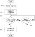
도 4는 본 발명에 의한 온수 공급 시스템의 제어방법을 보여주는 흐름도
도 5는 본 발명의 다른 실시예에 의한 순환모듈의 상세 구성을 보여주는 도면
** 부호의 설명 **
1 : 온수 공급 시스템 100,110 : 냉수유입관
120 : 온수공급배관 130 : 냉수공급배관
200 : 온수공급부 210 : 순환펌프
220 : 열교환기 230 : 버너
240 : 유량센서 300-1,300-2,300-3 : 수전
400 : 순환모듈 410 : 개폐밸브
420 : 온도센서 430 : 체크밸브
440 : 유량센서 450 : 연결배관
이하 첨부한 도면을 참조하여 본 발명의 바람직한 실시예에 대한 구성 및 작용을 상세히 설명하면 다음과 같다.
도 2와 도 3을 참조하여 본 발명에 의한 온수 공급 시스템의 구성에 대해 설명한다.
본 발명에 의한 온수 공급 시스템(1)은, 냉수유입관(100)을 통해 유입된 냉수를 가열하여 온수를 생성하는 온수공급부(200), 사용자로부터 온수 예열 신호가 입력되면 상기 온수공급부(200)로부터 가열된 물을 온수공급배관(120)과 냉수공급배관(130)으로 순환시키기 위한 순환모듈(400), 온수 공급 및 예열이 이루어지도록 제어하기 위한 제어부(미도시)로 이루어진다.
상기 온수공급부(200)의 내부에는 예열 모드시 물을 순환시키기 위한 순환펌프(210)가 구비된다.
상기 온수공급부(200)의 내부에는 온수를 생성하기 위하여 열교환기(220)와 버너(230)가 구비될 수 있다. 또한, 온수 공급을 위하여 냉수가 냉수유입관(100,110)을 통해 온수공급부(200) 내부로 유입되면 그 냉수의 흐름을 감지하기 위한 유량센서(240)가 구비될 수 있다.
이와 다르게 상기 온수공급부(200)를 온수를 저장하는 온수저장탱크로 구성하고, 물을 가열하여 온수저장탱크에 온수를 공급하는 별도의 장치를 구비하는 것으로 구성할 수도 있다. 이 경우에는 배관 연결도 변경되어야 한다.
상기 온수공급부(200)에서 생성된 온수와 냉수유입관(100)을 통해 유입된 냉수는 수전(300-1,300-2,300-3)을 통해 사용자에게 공급된다.
상기 온수공급부(200)와 수전(300-1,300-2,300-3) 및 순환모듈(400) 사이에는 다수의 배관에 의해 연결된다. 즉, 냉수가 유입되는 냉수유입관(100,110), 온수공급부(200)에서 공급된 온수를 수전(300-1,300-2,300-3)으로 공급하기 위한 온수공급배관(120), 상기 냉수유입관(100)을 통해 유입된 냉수를 수전(300-1,300-2,300-3)으로 공급하기 위한 냉수공급배관(130)이 구비된다.
상기 순환모듈(400)에는, 온수공급배관(120)과 냉수공급배관(130) 사이를 연결하는 연결배관(450)이 구비되고, 상기 연결배관(450) 상에 개폐밸브(410)와 온도센서(420)와 체크밸브(430)가 구비되며, 냉수공급배관(130)을 유동하는 물의 흐름을 감지하기 위한 유량센서(440)가 구비된다.
상기 순환모듈(400)은 모듈화되어 있어 온수공급배관(120)과 냉수공급배관(130)에 탈착 가능하도록 구비될 수 있다.
상기 개폐밸브(410)는 솔레노이드 밸브로 구성될 수 있고, 개폐밸브(410)가 온(On)되면 밸브가 개방되어 연결배관(450)을 통해 물의 유동이 허용되고, 개폐밸브(410)가 오프(Off)되면 밸브가 닫혀 연결배관(450)을 통한 물의 유동이 차단된다. 따라서 개폐밸브(410)가 오프(Off)되면 냉수공급배관(130)을 유동하는 물이 온수공급배관(120)으로 유동하는 것이 차단되고, 이와 반대로 온수공급배관(130)을 유동하는 물이 냉수공급배관(130)으로 유동하는 것도 차단된다.
상기 개폐밸브(410)는 물을 예열하는 예열모드시에만 온(On)되어 물의 순환이 이루어지도록 한다.
상기 온도센서(420)는 예열모드시 연결배관(450)을 유동하는 물의 온도를 측정하는 것으로, 그 측정된 온도가 제어부에 설정된 온도에 도달하면 제어부는 예열이 완료된 것으로 판단하여 개폐밸브(410)를 오프(Off)시키고, 순환펌프(210)의 가동을 정지시킨다.
상기 체크밸브(430)는 온수공급배관(120)에서 냉수공급배관(130)으로 물이 유동하는 것은 허용하되, 그 역방향의 유동을 차단하도록 구비된다.
예열모드가 가동되는 도중에는 개폐밸브(410)가 개방된 상태인데, 사용자의 온수 출수 요청에 의해 온수가 수전(300-1)을 통해 배출되는 경우에는 개폐밸브(410)를 닫는다. 이 경우 온수가 수전(300-1)을 통해 배출되는 것을 감지한 후 개폐밸브(410)가 닫히기까지 시간이 소요된다. 개폐밸브(410)가 닫히기 전에는 냉수공급배관(130)의 냉수가 연결배관(450)을 경유하여 온수공급배관(120)의 온수와 혼합된 후 수전(300-1)을 통해 배출될 수 있다. 따라서 체크밸브(430)가 없다면 냉수가 온수에 혼합되어 배출되므로 사용자가 원하는 온도의 온수를 신속히 공급하기 어렵다. 본 발명은 연결배관(450) 상에 체크밸브(430)를 구비함으로써 이러한 문제점을 해결하였다.
상기 유량센서(440)는 냉수공급배관(130)을 유동하는 물의 유량을 측정한다. 예열모드가 가동되는 도중에는 개폐밸브(410)가 개방된 상태이다. 이 상태에서 사용자의 냉수 출수 요청에 의해 냉수가 수전(300-1)을 통해 배출되는 경우에는 온수공급배관(120)의 물이 연결배관(450)을 경유하여 냉수공급배관(130)의 냉수와 혼합된 후 수전(300-1)을 통해 배출될 수 있으므로 사용자가 원하는 온도의 냉수를 신속히 공급하기 어렵다. 따라서 예열모드가 가동되는 도중에 상기 유량센서(440)에서 제어부에 설정된 유량의 흐름이 감지되면 개폐밸브(410)를 닫도록 제어함으로써 온수가 냉수와 혼합되어 배출되는 것을 방지할 수 있다.
도 4를 참조하여 본 발명에 의한 온수 공급 시스템의 제어방법에 대해 설명한다.
단계(S11)에서 사용자로부터 온수 예열 신호가 제어부에 입력된다.
여기서 온수 예열 신호는 사용자가 온수 사용 전에 온수를 예열하기 위해 발생시키는 신호로써, 버튼의 누름에 의해 발생하는 신호가 될 수도 있고, 센서의 감지에 의해 발생하는 신호가 될 수도 있다.
단계(S12)에서 제어부는 온수 예열 신호가 입력되면 예열모드를 진행한다. 예열모드가 진행되면, 버너(230)를 가동시켜 열교환기(220)에서 물을 가열시킴과 동시에 개폐밸브(410)와 순환펌프(210)를 온(On)시킨다. 온수공급부(200)에서 가열된 물은 순환펌프(210)에 의해 이송되어 온수공급배관(120), 연결배관(450), 냉수공급배관(130)을 순차 경유한 후 순환펌프(210)로 순환하게 된다.
단계(S13)에서 온도센서(420)에서 순환수의 온도를 측정하고, 측정된 순환수의 온도가 제어부에 설정된 온도에 도달하였는지 여부를 판단한다.
판단 결과 예열이 완료된 것으로 판단되면 단계(S15)로 진행하고, 그렇지 않으면 단계(S14)로 진행한다.
단계(S15)에서 예열이 완료되었으므로 개폐밸브(410)와 순환펌프(210)를 오프(Off)시키면 예열모드가 종료된다.
단계(S13)에서 순환수의 온도가 설정된 온도에 도달하기 전(즉, 예열모드가 종료되기 전)에 사용자가 온수를 사용하거나 냉수를 사용하는 경우가 있다. 이 경우에는 유량센서(240,440)에서 감지된 유량에 근거하여 예열모드를 종료시키기 것으로 구성할 수 있다.
즉, 예열모드 진행 중에 사용자가 온수 사용을 위해 수전(300-1)에 구비된 온수밸브(미도시)를 개방시키면, 냉수유입관(100,110)을 통해 온수공급부(200) 내부로 물이 유입된다. 사용자가 수전(300-1)의 온수밸브를 열기 전에는 예열모드의 진행에 따라, 온수공급부(200) 내부를 순환하는 순환수의 유량(이하 '제1유량'이라 함)이 유량센서(240)에 의해 감지되고 있다. 그 후 사용자가 수전(300-1)의 온수밸브를 열게 되면 냉수유입관(100,110)을 통해 냉수가 온수공급부(200) 내부로 유입되고, 이때 유량센서(240)에서 감지되는 유량(이하 '제2유량'이라 함)은 제1유량에 비해 증가한다. 제어부는 제1유량과 제2유량을 비교하여 설정된 차이 이상이 발생하여 예열모드시의 유량범위를 벗어났다고 판단되면 예열모드를 종료하고 온수 공급을 위해 개폐밸브(410)를 닫고, 순환펌프(210) 가동을 정지시킨다. 이 경우 연결배관(450) 상에 체크밸브(430)가 구비됨으로 인해, 개폐밸브(410)가 닫히기 전까지 냉수공급배관(130)의 물이 연결배관(450)을 경유하여 온수공급배관(120)으로 유입되는 것이 방지된다.
이 경우 상기 순환수의 유량인 제1유량은 순환모듈(400)에 구비된 유량센서(440)에 의해 감지된 유량으로 구성할 수도 있다.
한편, 예열모드 진행 중에 사용자가 냉수 사용을 위해 수전(300-1)에 구비된 냉수밸브(미도시)를 개방시키면, 냉수유입관(100)과 냉수공급배관(130)을 통해 냉수가 유입되어 수전(300-1)의 냉수밸브를 통해 사용자에게 배출된다. 이 경우 냉수공급배관(130) 상에 구비된 유량센서(440)에서 감지된 유량이 예열모드 진행 중에 감지된 유량과 비교하여 차이가 발생하게 된다. 제어부는 이러한 차이로부터 사용자가 냉수를 사용하고 있다고 판단되면 예열모드를 종료하고 냉수 공급을 위해 개폐밸브(410)를 닫고, 순환펌프(210) 가동을 정지시킨다. 이 경우 순환펌프(210) 가동이 정지되면 개폐밸브(410)가 닫히기 전에도 온수공급배관(120)의 물이 연결배관(450)을 통해 냉수공급배관(120)으로 유입되는 것은 차단된다.
단계(S15)에서 예열모드가 종료되면 사용자가 수전(300-1)의 온수밸브를 개방시켜 예열된 온수를 사용할 수 있다.
도 5를 참조하여 본 발명의 다른 실시예에 의한 순환모듈의 구성에 대해 설명한다.
앞선 실시예에서는 순환펌프(210)가 온수공급부(200) 내부에 구비된 것으로 예시하였으나, 본 실시예에서는 순환펌프(210)가 순환모듈(400) 내부에 구비된 것으로 구성하였다. 이와 같이 구성하면 온수 예열 기능이 없는 온수 공급 시스템에 순환펌프(210)가 구비된 순환모듈(400)을 추가함으로써 온수 예열 기능을 갖춘 온수 공급 시스템으로 변경이 가능하고, 온수 예열에 필요한 구성의 유지보수가 용이하다.
한편, 다른 실시예로서 순환펌프는 온수공급배관(120)과 냉수공급배관(130)을 연결하는 순환유로 상에 구비될 수도 있다.
본 발명은 상기 실시예에 한정되지 않고 본 발명의 기술적 요지를 벗어나지 아니하는 범위 내에서 다양하게 수정, 변형되어 실시될 수 있음은 본 발명이 속하는 기술분야에서 통상의 지식을 가진 자에 있어서 자명한 것이다.
Claims (12)
- 온수를 공급하는 온수공급부(200);상기 온수공급부(200)로부터 사용자에게 온수를 공급하기 위한 온수공급배관(120)과 냉수유입관(100)으로부터 유입된 냉수를 사용자에게 공급하기 위한 냉수공급배관(130) 사이를 연결하여 물의 유동을 허용하거나, 상기 연결을 차단함으로써 물의 유동을 차단하는 개폐밸브(410);상기 온수공급부(200)에서 공급된 물을 상기 온수공급배관(120)과 개폐밸브(410)와 냉수공급배관(130) 및 온수공급부(200)로 순환시키는 순환펌프(210);사용자의 온수 예열 신호가 입력되면 상기 개폐밸브(410)를 개방시키고, 상기 순환펌프(210)를 가동시켜 사용자에게 공급할 물을 예열시키는 제어부;로 이루어진 예열 기능이 구비된 온수 공급 시스템
- 제1항에 있어서,상기 온수공급배관(120)과 냉수공급배관(130) 사이를 연결하는 연결배관(450)이 구비되고, 상기 개폐밸브(410)는 상기 연결배관(450) 상에 구비된 것을 특징으로 하는 예열 기능이 구비된 온수 공급 시스템
- 제2항에 있어서,상기 연결배관(450) 상에는 상기 온수공급배관(120)에서 냉수공급배관(130) 방향으로의 유동만 허용하고 그 역방향의 유동을 차단시키는 체크밸브(430)가 구비된 것을 특징으로 하는 예열 기능이 구비된 온수 공급 시스템
- 제1항에 있어서,상기 순환펌프(210)에 의해 순환되는 물의 온도를 측정하기 위한 온도센서(420)가 구비되고;상기 온도센서(420)에서 측정된 온도를 기준으로 상기 개폐밸브(410)의 개폐가 이루어지는 것을 특징으로 하는 예열 기능이 구비된 온수 공급 시스템
- 제4항에 있어서,상기 온도센서(420)는 상기 온수공급배관(120)과 냉수공급배관(130) 사이를 연결하는 연결배관(450) 상에 구비된 것을 특징으로 하는 예열 기능이 구비된 온수 공급 시스템
- 제1항에 있어서,상기 냉수공급배관(130) 내부를 유동하는 물의 유량을 감지하기 위한 유량센서(440)가 구비되고;상기 유량센서(440)에서 측정된 유량을 기준으로 상기 개폐밸브(410)의 개폐를 제어하는 것을 특징으로 하는 예열 기능이 구비된 온수 공급 시스템
- 제1항에 있어서,상기 순환펌프(210)는 상기 온수공급부(200) 내부에 구비된 것을 특징으로 하는 예열 기능이 구비된 온수 공급 시스템
- 제1항에 있어서,상기 개폐밸브(410)는 순환모듈(400)의 내부에 구비되고, 상기 순환모듈(400)은 온수공급배관(120)과 냉수공급배관(130)에 연결되어 탈착 가능한 것을 특징으로 하는 예열 기능이 구비된 온수 공급 시스템
- 온수공급부(200)에서 온수를 온수공급배관(120)을 통해 사용자에게 공급하고, 사용자에게 냉수를 냉수공급배관(130)을 통해 공급하고, 제어부에서 순환펌프(210)를 제어하여 상기 온수공급부(200)로부터 공급된 온수를 상기 온수공급배관(120)과 냉수공급배관(130) 및 온수공급부(200)로 순환시키는 온수 공급 시스템의 제어방법에 있어서,a) 사용자로부터 온수 예열 신호가 상기 제어부에 입력되는 단계;b) 상기 온수공급배관(120)과 냉수공급배관(130) 사이를 연결하여 물의 유동이 허용되도록 개폐밸브(410)를 개방시키고, 상기 순환펌프(210)를 가동시켜 상기 온수공급부(200)에서 공급된 물을 상기 온수공급배관(120)과 냉수공급배관(130) 및 온수공급부(200)로 순환시켜 예열시키는 예열모드가 가동되는 단계;c) 상기 제어부에서 예열이 완료된 것으로 판단하면, 상기 개폐밸브(410)를 닫고, 상기 순환펌프(210)의 가동을 정지시켜 예열모드가 종료되는 단계;를 포함하는 예열 기능이 구비된 온수 시스템의 제어방법
- 제9항에 있어서,상기 b)단계에서는 상기 순환펌프(210)에 의해 순환되는 물의 온도를 온도센서(410)에서 감지하고;상기 c)단계에서는 상기 온도센서(410)에서 감지된 물의 온도가 상기 제어부에 설정된 온도에 도달된 경우 예열이 완료된 것으로 판단하고;상기 예열 완료 판단시 상기 제어부는 상기 순환펌프(210)의 가동을 정지시키고, 상기 개폐밸브(410)를 닫는 것을 특징으로 하는 예열 기능이 구비된 온수 시스템의 제어방법
- 제9항에 있어서,상기 b)단계에서는 상기 냉수공급배관(130) 내부를 통해 흐르는 물의 유량을 유량센서(440)에서 감지하고;상기 유량센서(440)에서 감지된 유량이 상기 제어부에 설정된 유량에 도달하면 사용자가 냉수를 사용하는 것으로 판단하여 상기 개폐밸브(410)를 닫고 상기 순환펌프(210)의 가동을 정지시키는 것을 특징으로 하는 예열 기능이 구비된 온수 시스템의 제어방법
- 제9항에 있어서,상기 온수공급부(200)로 냉수가 유입되도록 하는 냉수유입관(110)이 구비되고;상기 냉수유입관(110)을 통해 유입되는 냉수의 유량을 감지하는 유량센서(240)가 구비되며;상기 b)단계가 진행되는 도중 상기 유량센서(240)에서 감지된 유량이 상기 제어부에 설정된 유량범위를 벗어나도록 변동이 생기면 사용자가 온수를 사용하는 것으로 판단하여 상기 순환펌프(210)의 가동을 정지시키는 것을 특징으로 하는 예열 기능이 구비된 온수 시스템의 제어방법
Priority Applications (1)
| Application Number | Priority Date | Filing Date | Title |
|---|---|---|---|
| US16/068,991 US10648680B2 (en) | 2016-01-25 | 2016-12-09 | Hot water supply system having preheating function and method for controlling same |
Applications Claiming Priority (2)
| Application Number | Priority Date | Filing Date | Title |
|---|---|---|---|
| KR10-2016-0008701 | 2016-01-25 | ||
| KR1020160008701A KR101772956B1 (ko) | 2016-01-25 | 2016-01-25 | 예열 기능이 구비된 온수 공급 시스템 및 그 제어방법 |
Publications (2)
| Publication Number | Publication Date |
|---|---|
| WO2017131341A2 true WO2017131341A2 (ko) | 2017-08-03 |
| WO2017131341A3 WO2017131341A3 (ko) | 2018-03-08 |
Family
ID=59398435
Family Applications (1)
| Application Number | Title | Priority Date | Filing Date |
|---|---|---|---|
| PCT/KR2016/014444 Ceased WO2017131341A2 (ko) | 2016-01-25 | 2016-12-09 | 예열 기능이 구비된 온수 공급 시스템 및 그 제어방법 |
Country Status (3)
| Country | Link |
|---|---|
| US (1) | US10648680B2 (ko) |
| KR (1) | KR101772956B1 (ko) |
| WO (1) | WO2017131341A2 (ko) |
Families Citing this family (11)
| Publication number | Priority date | Publication date | Assignee | Title |
|---|---|---|---|---|
| TWM581677U (zh) * | 2018-12-14 | 2019-08-01 | 彭紹與 | Instant drinking water device |
| US11846433B2 (en) * | 2019-09-27 | 2023-12-19 | Rheem Manufacturing Company | Heated water recirculation control |
| CN112984610A (zh) * | 2021-04-02 | 2021-06-18 | 中山市乐喜电子科技有限公司 | 热水供应系统及其控制方法 |
| KR102815150B1 (ko) * | 2021-12-13 | 2025-06-02 | 주식회사 경동나비엔 | 유체 가열 장치 |
| GB2631177A (en) * | 2022-02-24 | 2024-12-25 | Kyungdong Navien Co Ltd | Hot water supply capable of hot water preheating and malfunction determination method using same |
| CN116105376B (zh) * | 2022-07-21 | 2025-09-30 | 宁波方太厨具有限公司 | 热水器及其预热控制方法、装置、计算机可读存储介质 |
| CN115289682B (zh) * | 2022-08-02 | 2024-12-27 | 宁波方太厨具有限公司 | 带有连接阀的预热循环及增压控制方法 |
| CN115289690B (zh) * | 2022-08-02 | 2024-12-17 | 宁波方太厨具有限公司 | 预热和增压用连接阀、水路系统、预热方法及增压方法 |
| KR102913880B1 (ko) * | 2022-11-11 | 2026-01-19 | 주식회사 경동나비엔 | 온수 공급 장치 및 그 제어 방법 |
| CN116602601B (zh) * | 2023-06-16 | 2026-02-17 | 艾欧史密斯(中国)热水器有限公司 | 联供系统及其控制方法 |
| CN119085132B (zh) * | 2024-08-06 | 2025-11-07 | 广东万家乐燃气具有限公司 | 一种低功耗定点预热控制方法及系统 |
Family Cites Families (13)
| Publication number | Priority date | Publication date | Assignee | Title |
|---|---|---|---|---|
| US5009572A (en) * | 1989-10-16 | 1991-04-23 | Ray Imhoff | Water conservation device |
| US5205318A (en) * | 1992-07-21 | 1993-04-27 | Sjoberg Industries, Inc. | Recirculation hot water system |
| US5261443A (en) * | 1993-01-04 | 1993-11-16 | Walsh Paul F | Watersaving recirculating system |
| US7198059B2 (en) * | 2000-10-25 | 2007-04-03 | Grundfos Pumps Manufacturing Company | Apparatus and system for retrofitting water control valves |
| US6962162B2 (en) * | 2001-11-09 | 2005-11-08 | Act, Inc. | Method for operating a multi family/commercial plumbing system |
| KR100465749B1 (ko) | 2003-01-23 | 2005-01-13 | 민경옥 | 가정용 보일러의 온수 공급장치 및 방법 |
| US6895985B2 (en) * | 2003-03-17 | 2005-05-24 | Computerized Smart Faucet Ltd. | Smart device and system for improved domestic use and saving of water |
| JP4113512B2 (ja) | 2004-03-31 | 2008-07-09 | 株式会社デンソー | 温水利用システム |
| KR100777626B1 (ko) * | 2005-04-20 | 2007-11-21 | 강인미 | 물 절약 시스템 및 물 절약 방법 |
| KR100985384B1 (ko) | 2008-06-27 | 2010-10-05 | 주식회사 경동네트웍 | 온수 공급 시스템에서 저유량의 온수 사용시 온수 온도를제어하기 위한 방법 |
| US20100126604A1 (en) * | 2008-11-18 | 2010-05-27 | Lund William J | System and Method for On Demand Hot Water Distribution |
| KR20110032135A (ko) | 2009-09-22 | 2011-03-30 | 김현수 | 온수절약장치 |
| JP6092815B2 (ja) * | 2014-06-06 | 2017-03-08 | リンナイ株式会社 | 給湯装置 |
-
2016
- 2016-01-25 KR KR1020160008701A patent/KR101772956B1/ko active Active
- 2016-12-09 US US16/068,991 patent/US10648680B2/en active Active
- 2016-12-09 WO PCT/KR2016/014444 patent/WO2017131341A2/ko not_active Ceased
Also Published As
| Publication number | Publication date |
|---|---|
| US20190078794A1 (en) | 2019-03-14 |
| KR20170088611A (ko) | 2017-08-02 |
| KR101772956B1 (ko) | 2017-08-30 |
| US10648680B2 (en) | 2020-05-12 |
| WO2017131341A3 (ko) | 2018-03-08 |
Similar Documents
| Publication | Publication Date | Title |
|---|---|---|
| WO2017131341A2 (ko) | 예열 기능이 구비된 온수 공급 시스템 및 그 제어방법 | |
| WO2013005976A2 (ko) | 가스 온수기 및 이를 구비한 온수공급장치 | |
| WO2012053679A1 (ko) | 순환펌프 운전을 통한 온수 온도 제어방법 | |
| WO2013165106A1 (ko) | 난방효율을 향상시킨 난방 및 온수의 동시 사용이 가능한 보일러 | |
| WO2017111364A1 (ko) | 난방 온수 겸용 보일러 및 그 제어방법 | |
| WO2016099171A1 (ko) | 감압밸브가 구비된 온수 공급 장치 | |
| WO2019124821A1 (ko) | 온수공급장치 및 온수공급장치의 폐열 활용 방법 | |
| WO2019124820A1 (ko) | 온수공급장치 및 그 제어방법 | |
| WO2013168926A1 (ko) | 사용자의 온수 사용 패턴에 따른 온수기의 온수 예열 제어방법 | |
| WO2018021804A1 (ko) | 직수공급관을 이용한 온수 재순환 밸브 | |
| CN110440454A (zh) | 一种燃气热水器外部控制模块及其燃气热水器系统及控制方法 | |
| WO2015133686A1 (ko) | 배기가스의 폐열을 이용한 난방용 온풍기 | |
| WO2017010666A1 (ko) | 차량용 온수 제공 장치 | |
| WO2019022366A1 (ko) | 난방 및 온수 겸용 보일러 시스템 | |
| WO2019004625A1 (ko) | 예열 기능이 구비된 온수공급장치 및 그 제어방법 | |
| WO2016099172A1 (ko) | 지역 및 중앙 난방에 적용되는 세대별 난방 및 온수 공급 장치 및 환수 온도 제어 방법 | |
| WO2018124651A1 (ko) | 밀폐식 보일러의 물 보충 장치 및 물 보충 방법 | |
| WO2017183754A1 (ko) | 유기물 랭킨 사이클을 이용한 발전장치 | |
| WO2015030371A1 (ko) | 에어 핸들러 시스템의 난방 중 온수사용 판단방법 | |
| WO2016143924A1 (ko) | 태양열 온수시스템 | |
| WO2016129757A1 (ko) | 온수 순환배관장치 | |
| JP2003240336A (ja) | 燃料使用量の算出方法および温水暖房熱源機 | |
| JP3465533B2 (ja) | 補助給湯器接続ユニットおよびソーラー給湯機能付給湯装置 | |
| WO2017026737A1 (ko) | 온수 공급 시스템에서의 배관의 위치별 온도 측정 방법 | |
| WO2019054605A1 (ko) | 설치환경에 따른 효율적인 온수 예열시간 자동 판단 제어방법 |
Legal Events
| Date | Code | Title | Description |
|---|---|---|---|
| 121 | Ep: the epo has been informed by wipo that ep was designated in this application |
Ref document number: 16888317 Country of ref document: EP Kind code of ref document: A2 |
|
| NENP | Non-entry into the national phase |
Ref country code: DE |
|
| 122 | Ep: pct application non-entry in european phase |
Ref document number: 16888317 Country of ref document: EP Kind code of ref document: A2 |