WO2017131013A1 - Refrigeration cycle device - Google Patents
Refrigeration cycle device Download PDFInfo
- Publication number
- WO2017131013A1 WO2017131013A1 PCT/JP2017/002496 JP2017002496W WO2017131013A1 WO 2017131013 A1 WO2017131013 A1 WO 2017131013A1 JP 2017002496 W JP2017002496 W JP 2017002496W WO 2017131013 A1 WO2017131013 A1 WO 2017131013A1
- Authority
- WO
- WIPO (PCT)
- Prior art keywords
- working medium
- hfo
- refrigeration cycle
- compressor
- cycle apparatus
- Prior art date
Links
- 238000005057 refrigeration Methods 0.000 title claims abstract description 110
- 230000006835 compression Effects 0.000 claims abstract description 32
- 238000007906 compression Methods 0.000 claims abstract description 32
- 239000011810 insulating material Substances 0.000 claims abstract description 19
- WABPQHHGFIMREM-UHFFFAOYSA-N lead(0) Chemical compound [Pb] WABPQHHGFIMREM-UHFFFAOYSA-N 0.000 claims description 53
- MIZLGWKEZAPEFJ-UHFFFAOYSA-N 1,1,2-trifluoroethene Chemical group FC=C(F)F MIZLGWKEZAPEFJ-UHFFFAOYSA-N 0.000 claims description 11
- RWRIWBAIICGTTQ-UHFFFAOYSA-N difluoromethane Chemical compound FCF RWRIWBAIICGTTQ-UHFFFAOYSA-N 0.000 description 62
- 239000000203 mixture Substances 0.000 description 43
- FXRLMCRCYDHQFW-UHFFFAOYSA-N 2,3,3,3-tetrafluoropropene Chemical compound FC(=C)C(F)(F)F FXRLMCRCYDHQFW-UHFFFAOYSA-N 0.000 description 41
- 238000007323 disproportionation reaction Methods 0.000 description 18
- LVGUZGTVOIAKKC-UHFFFAOYSA-N 1,1,1,2-tetrafluoroethane Chemical compound FCC(F)(F)F LVGUZGTVOIAKKC-UHFFFAOYSA-N 0.000 description 15
- GTLACDSXYULKMZ-UHFFFAOYSA-N pentafluoroethane Chemical compound FC(F)C(F)(F)F GTLACDSXYULKMZ-UHFFFAOYSA-N 0.000 description 15
- 239000012530 fluid Substances 0.000 description 13
- 239000011347 resin Substances 0.000 description 13
- 229920005989 resin Polymers 0.000 description 13
- 238000010586 diagram Methods 0.000 description 12
- 238000003780 insertion Methods 0.000 description 11
- 230000037431 insertion Effects 0.000 description 11
- 239000007788 liquid Substances 0.000 description 11
- 239000000463 material Substances 0.000 description 10
- 238000010792 warming Methods 0.000 description 9
- 150000001875 compounds Chemical class 0.000 description 8
- CBENFWSGALASAD-UHFFFAOYSA-N Ozone Chemical compound [O-][O+]=O CBENFWSGALASAD-UHFFFAOYSA-N 0.000 description 7
- 230000008859 change Effects 0.000 description 7
- 239000011248 coating agent Substances 0.000 description 7
- 238000000576 coating method Methods 0.000 description 7
- 230000007246 mechanism Effects 0.000 description 7
- 239000003507 refrigerant Substances 0.000 description 7
- 238000000034 method Methods 0.000 description 6
- 230000002093 peripheral effect Effects 0.000 description 6
- CDOOAUSHHFGWSA-OWOJBTEDSA-N (e)-1,3,3,3-tetrafluoroprop-1-ene Chemical compound F\C=C\C(F)(F)F CDOOAUSHHFGWSA-OWOJBTEDSA-N 0.000 description 5
- 239000004215 Carbon black (E152) Substances 0.000 description 5
- 230000002159 abnormal effect Effects 0.000 description 5
- 229930195733 hydrocarbon Natural products 0.000 description 5
- 150000002430 hydrocarbons Chemical class 0.000 description 5
- 238000006243 chemical reaction Methods 0.000 description 4
- 238000000354 decomposition reaction Methods 0.000 description 4
- 230000008569 process Effects 0.000 description 4
- NPNPZTNLOVBDOC-UHFFFAOYSA-N 1,1-difluoroethane Chemical compound CC(F)F NPNPZTNLOVBDOC-UHFFFAOYSA-N 0.000 description 3
- QTBSBXVTEAMEQO-UHFFFAOYSA-N Acetic acid Chemical compound CC(O)=O QTBSBXVTEAMEQO-UHFFFAOYSA-N 0.000 description 3
- -1 HFC -152a Chemical compound 0.000 description 3
- XEEYBQQBJWHFJM-UHFFFAOYSA-N Iron Chemical group [Fe] XEEYBQQBJWHFJM-UHFFFAOYSA-N 0.000 description 3
- 239000011203 carbon fibre reinforced carbon Substances 0.000 description 3
- 230000007547 defect Effects 0.000 description 3
- 238000007599 discharging Methods 0.000 description 3
- 230000000694 effects Effects 0.000 description 3
- 239000003779 heat-resistant material Substances 0.000 description 3
- 230000001771 impaired effect Effects 0.000 description 3
- 238000009413 insulation Methods 0.000 description 3
- OFBQJSOFQDEBGM-UHFFFAOYSA-N n-pentane Natural products CCCCC OFBQJSOFQDEBGM-UHFFFAOYSA-N 0.000 description 3
- XLYOFNOQVPJJNP-UHFFFAOYSA-N water Substances O XLYOFNOQVPJJNP-UHFFFAOYSA-N 0.000 description 3
- UJPMYEOUBPIPHQ-UHFFFAOYSA-N 1,1,1-trifluoroethane Chemical compound CC(F)(F)F UJPMYEOUBPIPHQ-UHFFFAOYSA-N 0.000 description 2
- WXGNWUVNYMJENI-UHFFFAOYSA-N 1,1,2,2-tetrafluoroethane Chemical compound FC(F)C(F)F WXGNWUVNYMJENI-UHFFFAOYSA-N 0.000 description 2
- CURLTUGMZLYLDI-UHFFFAOYSA-N Carbon dioxide Chemical compound O=C=O CURLTUGMZLYLDI-UHFFFAOYSA-N 0.000 description 2
- ATUOYWHBWRKTHZ-UHFFFAOYSA-N Propane Chemical compound CCC ATUOYWHBWRKTHZ-UHFFFAOYSA-N 0.000 description 2
- VYPSYNLAJGMNEJ-UHFFFAOYSA-N Silicium dioxide Chemical compound O=[Si]=O VYPSYNLAJGMNEJ-UHFFFAOYSA-N 0.000 description 2
- 239000010425 asbestos Substances 0.000 description 2
- 230000020169 heat generation Effects 0.000 description 2
- 239000004615 ingredient Substances 0.000 description 2
- NNPPMTNAJDCUHE-UHFFFAOYSA-N isobutane Chemical compound CC(C)C NNPPMTNAJDCUHE-UHFFFAOYSA-N 0.000 description 2
- QWTDNUCVQCZILF-UHFFFAOYSA-N isopentane Chemical compound CCC(C)C QWTDNUCVQCZILF-UHFFFAOYSA-N 0.000 description 2
- 239000000155 melt Substances 0.000 description 2
- 229910052895 riebeckite Inorganic materials 0.000 description 2
- 238000004804 winding Methods 0.000 description 2
- UPVJEODAZWTJKZ-OWOJBTEDSA-N (e)-1,2-dichloro-1,2-difluoroethene Chemical group F\C(Cl)=C(\F)Cl UPVJEODAZWTJKZ-OWOJBTEDSA-N 0.000 description 1
- NVSXSBBVEDNGPY-UHFFFAOYSA-N 1,1,1,2,2-pentafluorobutane Chemical compound CCC(F)(F)C(F)(F)F NVSXSBBVEDNGPY-UHFFFAOYSA-N 0.000 description 1
- NSGXIBWMJZWTPY-UHFFFAOYSA-N 1,1,1,3,3,3-hexafluoropropane Chemical compound FC(F)(F)CC(F)(F)F NSGXIBWMJZWTPY-UHFFFAOYSA-N 0.000 description 1
- IDBYQQQHBYGLEQ-UHFFFAOYSA-N 1,1,2,2,3,3,4-heptafluorocyclopentane Chemical compound FC1CC(F)(F)C(F)(F)C1(F)F IDBYQQQHBYGLEQ-UHFFFAOYSA-N 0.000 description 1
- QGYLHZMNVGBXDQ-UHFFFAOYSA-N 1,1-dichloro-2,3,3,3-tetrafluoroprop-1-ene Chemical compound ClC(Cl)=C(F)C(F)(F)F QGYLHZMNVGBXDQ-UHFFFAOYSA-N 0.000 description 1
- FPBWSPZHCJXUBL-UHFFFAOYSA-N 1-chloro-1-fluoroethene Chemical group FC(Cl)=C FPBWSPZHCJXUBL-UHFFFAOYSA-N 0.000 description 1
- BLEZTPDKUBSTII-UHFFFAOYSA-N 1-chloro-1-fluoroprop-1-ene Chemical compound CC=C(F)Cl BLEZTPDKUBSTII-UHFFFAOYSA-N 0.000 description 1
- GDPWRLVSJWKGPJ-UHFFFAOYSA-N 1-chloro-2,3,3,3-tetrafluoroprop-1-ene Chemical compound ClC=C(F)C(F)(F)F GDPWRLVSJWKGPJ-UHFFFAOYSA-N 0.000 description 1
- 125000003903 2-propenyl group Chemical group [H]C([*])([H])C([H])=C([H])[H] 0.000 description 1
- LVZWSLJZHVFIQJ-UHFFFAOYSA-N Cyclopropane Chemical compound C1CC1 LVZWSLJZHVFIQJ-UHFFFAOYSA-N 0.000 description 1
- 239000004641 Diallyl-phthalate Substances 0.000 description 1
- 239000004677 Nylon Substances 0.000 description 1
- 239000004696 Poly ether ether ketone Substances 0.000 description 1
- 239000004962 Polyamide-imide Substances 0.000 description 1
- 239000004693 Polybenzimidazole Substances 0.000 description 1
- 239000004697 Polyetherimide Substances 0.000 description 1
- 239000004734 Polyphenylene sulfide Substances 0.000 description 1
- XUIMIQQOPSSXEZ-UHFFFAOYSA-N Silicon Chemical compound [Si] XUIMIQQOPSSXEZ-UHFFFAOYSA-N 0.000 description 1
- SMEGJBVQLJJKKX-HOTMZDKISA-N [(2R,3S,4S,5R,6R)-5-acetyloxy-3,4,6-trihydroxyoxan-2-yl]methyl acetate Chemical compound CC(=O)OC[C@@H]1[C@H]([C@@H]([C@H]([C@@H](O1)O)OC(=O)C)O)O SMEGJBVQLJJKKX-HOTMZDKISA-N 0.000 description 1
- 229940081735 acetylcellulose Drugs 0.000 description 1
- PNEYBMLMFCGWSK-UHFFFAOYSA-N aluminium oxide Inorganic materials [O-2].[O-2].[O-2].[Al+3].[Al+3] PNEYBMLMFCGWSK-UHFFFAOYSA-N 0.000 description 1
- 230000015572 biosynthetic process Effects 0.000 description 1
- QUDWYFHPNIMBFC-UHFFFAOYSA-N bis(prop-2-enyl) benzene-1,2-dicarboxylate Chemical compound C=CCOC(=O)C1=CC=CC=C1C(=O)OCC=C QUDWYFHPNIMBFC-UHFFFAOYSA-N 0.000 description 1
- 239000001273 butane Substances 0.000 description 1
- 125000004432 carbon atom Chemical group C* 0.000 description 1
- 239000001569 carbon dioxide Substances 0.000 description 1
- 229910002092 carbon dioxide Inorganic materials 0.000 description 1
- 229920002301 cellulose acetate Polymers 0.000 description 1
- 239000012461 cellulose resin Substances 0.000 description 1
- 238000009833 condensation Methods 0.000 description 1
- 230000005494 condensation Effects 0.000 description 1
- 238000001816 cooling Methods 0.000 description 1
- 125000004122 cyclic group Chemical group 0.000 description 1
- 230000007423 decrease Effects 0.000 description 1
- AFABGHUZZDYHJO-UHFFFAOYSA-N dimethyl butane Natural products CCCC(C)C AFABGHUZZDYHJO-UHFFFAOYSA-N 0.000 description 1
- 238000001704 evaporation Methods 0.000 description 1
- 230000008020 evaporation Effects 0.000 description 1
- 230000002349 favourable effect Effects 0.000 description 1
- 238000010438 heat treatment Methods 0.000 description 1
- UKACHOXRXFQJFN-UHFFFAOYSA-N heptafluoropropane Chemical compound FC(F)C(F)(F)C(F)(F)F UKACHOXRXFQJFN-UHFFFAOYSA-N 0.000 description 1
- 238000005470 impregnation Methods 0.000 description 1
- 230000006872 improvement Effects 0.000 description 1
- 229910052500 inorganic mineral Inorganic materials 0.000 description 1
- 239000001282 iso-butane Substances 0.000 description 1
- 239000000395 magnesium oxide Substances 0.000 description 1
- CPLXHLVBOLITMK-UHFFFAOYSA-N magnesium oxide Inorganic materials [Mg]=O CPLXHLVBOLITMK-UHFFFAOYSA-N 0.000 description 1
- AXZKOIWUVFPNLO-UHFFFAOYSA-N magnesium;oxygen(2-) Chemical compound [O-2].[Mg+2] AXZKOIWUVFPNLO-UHFFFAOYSA-N 0.000 description 1
- 238000004519 manufacturing process Methods 0.000 description 1
- 239000010445 mica Substances 0.000 description 1
- 229910052618 mica group Inorganic materials 0.000 description 1
- 239000011707 mineral Substances 0.000 description 1
- 238000002156 mixing Methods 0.000 description 1
- 238000012986 modification Methods 0.000 description 1
- 230000004048 modification Effects 0.000 description 1
- IJDNQMDRQITEOD-UHFFFAOYSA-N n-butane Chemical compound CCCC IJDNQMDRQITEOD-UHFFFAOYSA-N 0.000 description 1
- 229920001778 nylon Polymers 0.000 description 1
- 239000003921 oil Substances 0.000 description 1
- MSSNHSVIGIHOJA-UHFFFAOYSA-N pentafluoropropane Chemical compound FC(F)CC(F)(F)F MSSNHSVIGIHOJA-UHFFFAOYSA-N 0.000 description 1
- 229920002312 polyamide-imide Polymers 0.000 description 1
- 229920002480 polybenzimidazole Polymers 0.000 description 1
- 229920001707 polybutylene terephthalate Polymers 0.000 description 1
- 229920002530 polyetherether ketone Polymers 0.000 description 1
- 229920001601 polyetherimide Polymers 0.000 description 1
- 229920001721 polyimide Polymers 0.000 description 1
- 239000009719 polyimide resin Substances 0.000 description 1
- 229920000069 polyphenylene sulfide Polymers 0.000 description 1
- 239000004810 polytetrafluoroethylene Substances 0.000 description 1
- 229920001343 polytetrafluoroethylene Polymers 0.000 description 1
- 230000002265 prevention Effects 0.000 description 1
- 239000001294 propane Substances 0.000 description 1
- QQONPFPTGQHPMA-UHFFFAOYSA-N propylene Natural products CC=C QQONPFPTGQHPMA-UHFFFAOYSA-N 0.000 description 1
- 125000004805 propylene group Chemical group [H]C([H])([H])C([H])([*:1])C([H])([H])[*:2] 0.000 description 1
- 239000010453 quartz Substances 0.000 description 1
- 150000003254 radicals Chemical class 0.000 description 1
- 229910052710 silicon Inorganic materials 0.000 description 1
- 239000010703 silicon Substances 0.000 description 1
- 229920002379 silicone rubber Polymers 0.000 description 1
Images


Classifications
-
- F—MECHANICAL ENGINEERING; LIGHTING; HEATING; WEAPONS; BLASTING
- F04—POSITIVE - DISPLACEMENT MACHINES FOR LIQUIDS; PUMPS FOR LIQUIDS OR ELASTIC FLUIDS
- F04B—POSITIVE-DISPLACEMENT MACHINES FOR LIQUIDS; PUMPS
- F04B39/00—Component parts, details, or accessories, of pumps or pumping systems specially adapted for elastic fluids, not otherwise provided for in, or of interest apart from, groups F04B25/00 - F04B37/00
-
- H—ELECTRICITY
- H01—ELECTRIC ELEMENTS
- H01R—ELECTRICALLY-CONDUCTIVE CONNECTIONS; STRUCTURAL ASSOCIATIONS OF A PLURALITY OF MUTUALLY-INSULATED ELECTRICAL CONNECTING ELEMENTS; COUPLING DEVICES; CURRENT COLLECTORS
- H01R4/00—Electrically-conductive connections between two or more conductive members in direct contact, i.e. touching one another; Means for effecting or maintaining such contact; Electrically-conductive connections having two or more spaced connecting locations for conductors and using contact members penetrating insulation
- H01R4/70—Insulation of connections
-
- F—MECHANICAL ENGINEERING; LIGHTING; HEATING; WEAPONS; BLASTING
- F04—POSITIVE - DISPLACEMENT MACHINES FOR LIQUIDS; PUMPS FOR LIQUIDS OR ELASTIC FLUIDS
- F04C—ROTARY-PISTON, OR OSCILLATING-PISTON, POSITIVE-DISPLACEMENT MACHINES FOR LIQUIDS; ROTARY-PISTON, OR OSCILLATING-PISTON, POSITIVE-DISPLACEMENT PUMPS
- F04C29/00—Component parts, details or accessories of pumps or pumping installations, not provided for in groups F04C18/00 - F04C28/00
-
- F—MECHANICAL ENGINEERING; LIGHTING; HEATING; WEAPONS; BLASTING
- F25—REFRIGERATION OR COOLING; COMBINED HEATING AND REFRIGERATION SYSTEMS; HEAT PUMP SYSTEMS; MANUFACTURE OR STORAGE OF ICE; LIQUEFACTION SOLIDIFICATION OF GASES
- F25B—REFRIGERATION MACHINES, PLANTS OR SYSTEMS; COMBINED HEATING AND REFRIGERATION SYSTEMS; HEAT PUMP SYSTEMS
- F25B1/00—Compression machines, plants or systems with non-reversible cycle
- F25B1/04—Compression machines, plants or systems with non-reversible cycle with compressor of rotary type
-
- F—MECHANICAL ENGINEERING; LIGHTING; HEATING; WEAPONS; BLASTING
- F25—REFRIGERATION OR COOLING; COMBINED HEATING AND REFRIGERATION SYSTEMS; HEAT PUMP SYSTEMS; MANUFACTURE OR STORAGE OF ICE; LIQUEFACTION SOLIDIFICATION OF GASES
- F25B—REFRIGERATION MACHINES, PLANTS OR SYSTEMS; COMBINED HEATING AND REFRIGERATION SYSTEMS; HEAT PUMP SYSTEMS
- F25B49/00—Arrangement or mounting of control or safety devices
- F25B49/02—Arrangement or mounting of control or safety devices for compression type machines, plants or systems
-
- F—MECHANICAL ENGINEERING; LIGHTING; HEATING; WEAPONS; BLASTING
- F04—POSITIVE - DISPLACEMENT MACHINES FOR LIQUIDS; PUMPS FOR LIQUIDS OR ELASTIC FLUIDS
- F04C—ROTARY-PISTON, OR OSCILLATING-PISTON, POSITIVE-DISPLACEMENT MACHINES FOR LIQUIDS; ROTARY-PISTON, OR OSCILLATING-PISTON, POSITIVE-DISPLACEMENT PUMPS
- F04C2210/00—Fluid
- F04C2210/26—Refrigerants with particular properties, e.g. HFC-134a
-
- F—MECHANICAL ENGINEERING; LIGHTING; HEATING; WEAPONS; BLASTING
- F04—POSITIVE - DISPLACEMENT MACHINES FOR LIQUIDS; PUMPS FOR LIQUIDS OR ELASTIC FLUIDS
- F04C—ROTARY-PISTON, OR OSCILLATING-PISTON, POSITIVE-DISPLACEMENT MACHINES FOR LIQUIDS; ROTARY-PISTON, OR OSCILLATING-PISTON, POSITIVE-DISPLACEMENT PUMPS
- F04C2240/00—Components
- F04C2240/40—Electric motor
-
- F—MECHANICAL ENGINEERING; LIGHTING; HEATING; WEAPONS; BLASTING
- F04—POSITIVE - DISPLACEMENT MACHINES FOR LIQUIDS; PUMPS FOR LIQUIDS OR ELASTIC FLUIDS
- F04C—ROTARY-PISTON, OR OSCILLATING-PISTON, POSITIVE-DISPLACEMENT MACHINES FOR LIQUIDS; ROTARY-PISTON, OR OSCILLATING-PISTON, POSITIVE-DISPLACEMENT PUMPS
- F04C2240/00—Components
- F04C2240/80—Other components
- F04C2240/803—Electric connectors or cables; Fittings therefor
-
- F—MECHANICAL ENGINEERING; LIGHTING; HEATING; WEAPONS; BLASTING
- F25—REFRIGERATION OR COOLING; COMBINED HEATING AND REFRIGERATION SYSTEMS; HEAT PUMP SYSTEMS; MANUFACTURE OR STORAGE OF ICE; LIQUEFACTION SOLIDIFICATION OF GASES
- F25B—REFRIGERATION MACHINES, PLANTS OR SYSTEMS; COMBINED HEATING AND REFRIGERATION SYSTEMS; HEAT PUMP SYSTEMS
- F25B2400/00—General features or devices for refrigeration machines, plants or systems, combined heating and refrigeration systems or heat-pump systems, i.e. not limited to a particular subgroup of F25B
- F25B2400/07—Details of compressors or related parts
-
- F—MECHANICAL ENGINEERING; LIGHTING; HEATING; WEAPONS; BLASTING
- F25—REFRIGERATION OR COOLING; COMBINED HEATING AND REFRIGERATION SYSTEMS; HEAT PUMP SYSTEMS; MANUFACTURE OR STORAGE OF ICE; LIQUEFACTION SOLIDIFICATION OF GASES
- F25B—REFRIGERATION MACHINES, PLANTS OR SYSTEMS; COMBINED HEATING AND REFRIGERATION SYSTEMS; HEAT PUMP SYSTEMS
- F25B2500/00—Problems to be solved
- F25B2500/11—Reducing heat transfers
-
- F—MECHANICAL ENGINEERING; LIGHTING; HEATING; WEAPONS; BLASTING
- F25—REFRIGERATION OR COOLING; COMBINED HEATING AND REFRIGERATION SYSTEMS; HEAT PUMP SYSTEMS; MANUFACTURE OR STORAGE OF ICE; LIQUEFACTION SOLIDIFICATION OF GASES
- F25D—REFRIGERATORS; COLD ROOMS; ICE-BOXES; COOLING OR FREEZING APPARATUS NOT OTHERWISE PROVIDED FOR
- F25D2201/00—Insulation
- F25D2201/10—Insulation with respect to heat
Definitions
- the present invention relates to a refrigeration cycle apparatus using a working medium containing 1,1,2-trifluoroethylene.
- HFC hydrofluorocarbon
- GWP global warming potential
- Patent Document 1 describes a refrigeration cycle apparatus using a working medium containing 1,1,2-trifluoroethylene (HFO-1123).
- a disproportionation reaction is a chemical reaction in which two or more of the same type of molecule react with each other to produce two or more different types of products.
- the present invention has been made in view of the above background, and when a working medium containing HFO-1123 is used, a refrigeration cycle apparatus capable of effectively suppressing the occurrence of a disproportionation reaction of HFO-1123.
- the purpose is to provide.
- a refrigeration cycle apparatus is a refrigeration cycle apparatus that performs a refrigeration cycle by compressing a working medium containing 1,1,2-trifluoroethylene with a compressor, the compressor comprising: A compression means for compressing the working medium, a drive means for driving the compression means, a power supply terminal for supplying electric power from the outside to the inside of the compressor, and the drive means and the power supply terminal electrically A plurality of lead wires for connection, and each of the plurality of lead wires is covered with an insulating material having a heat resistance of 300 ° C. or higher at least in a portion bound to each other.
- the plurality of lead wires and the power supply terminal are connected via a connector, and the connector has a heat resistance of 300 ° C. or higher.
- the connector has a heat resistance of 300 ° C. or higher.
- a plurality of the lead wires are inserted into the connector at angles in directions away from each other.
- a refrigeration cycle apparatus is a refrigeration cycle apparatus that performs a refrigeration cycle by compressing a working medium containing 1,1,2-trifluoroethylene with a compressor, the compressor comprising: A compression means for compressing the working medium, a drive means for driving the compression means, a power supply terminal for supplying electric power from the outside to the inside of the compressor, and the drive means and the power supply terminal electrically A plurality of lead wires for connection, and an insulating material having a heat resistance of 300 ° C. or more and having a plurality of through holes spaced apart from each other, and each of the plurality of lead wires includes a plurality of lead wires A portion of the lead wire is disposed through the plurality of through holes of the insulating material.
- the refrigeration cycle apparatus is the above-described refrigeration cycle apparatus, wherein the lead wire and the power supply terminal are connected via a connector, and the connector has an insulating material having a heat resistance of 300 ° C. or higher. Formed with.
- a plurality of the lead wires are inserted into the connector at angles in directions away from each other.
- a refrigeration cycle apparatus is a refrigeration cycle apparatus that performs a refrigeration cycle by compressing a working medium containing 1,1,2-trifluoroethylene with a compressor, the compressor comprising: A compression means for compressing the working medium, a drive means for driving the compression means, a power supply terminal for supplying electric power from the outside to the inside of the compressor, and the drive means and the power supply terminal electrically A plurality of lead wires for connection, wherein the lead wires and the power supply terminal are connected via a connector, and the connector is formed of an insulating material having a heat resistance of 300 ° C. or higher.
- a plurality of the lead wires are inserted into the connector at an angle in directions away from each other.
- a refrigeration cycle apparatus is a refrigeration cycle apparatus that performs a refrigeration cycle by compressing a working medium containing 1,1,2-trifluoroethylene with a compressor, the compressor comprising: A compression means for compressing the working medium, a drive means for driving the compression means, a power supply terminal for supplying electric power from the outside to the inside of the compressor, and the drive means and the power supply terminal electrically A plurality of lead wires for connection, the drive means and the power supply terminal are connected by a plurality of covered lead wires, the lead wire and the power supply terminal are connected via a connector, A plurality of the lead wires are inserted into the connector at angles in directions away from each other.
- the refrigeration cycle apparatus of the present invention when a working medium containing HFO-1123 is used, even if the inside of the refrigeration cycle becomes an abnormally high temperature or high pressure condition, the disproportionation reaction of HFO-1123 occurs. Can be effectively suppressed.
- FIG. 1 is a schematic configuration diagram illustrating an example of a refrigeration cycle apparatus according to the first embodiment.
- FIG. 2 is a pressure-enthalpy diagram showing a change in state of the working medium of the refrigeration cycle apparatus according to the first embodiment.
- FIG. 3 is a longitudinal sectional view illustrating a schematic configuration of the compressor in the refrigeration cycle apparatus according to the first embodiment. 4 is a cross-sectional view taken along the line IV-IV in FIG.
- FIG. 5 is a diagram illustrating a general configuration of a lead wire portion in a compressor used in an existing refrigeration cycle apparatus.
- FIG. 6 is a diagram illustrating a schematic configuration of a lead wire portion in the compressor of the refrigeration cycle apparatus according to the first embodiment.
- FIG. 1 is a schematic configuration diagram illustrating an example of a refrigeration cycle apparatus according to the first embodiment.
- FIG. 2 is a pressure-enthalpy diagram showing a change in state of the working medium of the refrigeration cycle apparatus according to the first embodiment.
- FIG. 3 is a longitudinal sectional
- FIG. 7 is a diagram illustrating a schematic configuration of the lead wire portion in the second embodiment.
- FIG. 8 is a perspective view showing an appearance of the insulating member of the lead wire portion in the second embodiment.
- FIG. 9 is a top view of the insulating member of the lead wire portion in the second embodiment.
- FIG. 10 is a diagram illustrating a schematic configuration of the lead wire portion in the third embodiment.
- FIG. 11 is an enlarged view of the peripheral portion of the connector in the lead wire portion of the compressor used in the existing refrigeration cycle apparatus shown in FIG.
- FIG. 12 is an enlarged view of the peripheral portion of the connector of the lead wire portion in the fourth embodiment.
- Embodiment 1 Embodiment 1 of the present invention will be described below with reference to the drawings.
- the working medium used in the present invention includes 1,1,2-trifluoroethylene (HFO-1123).
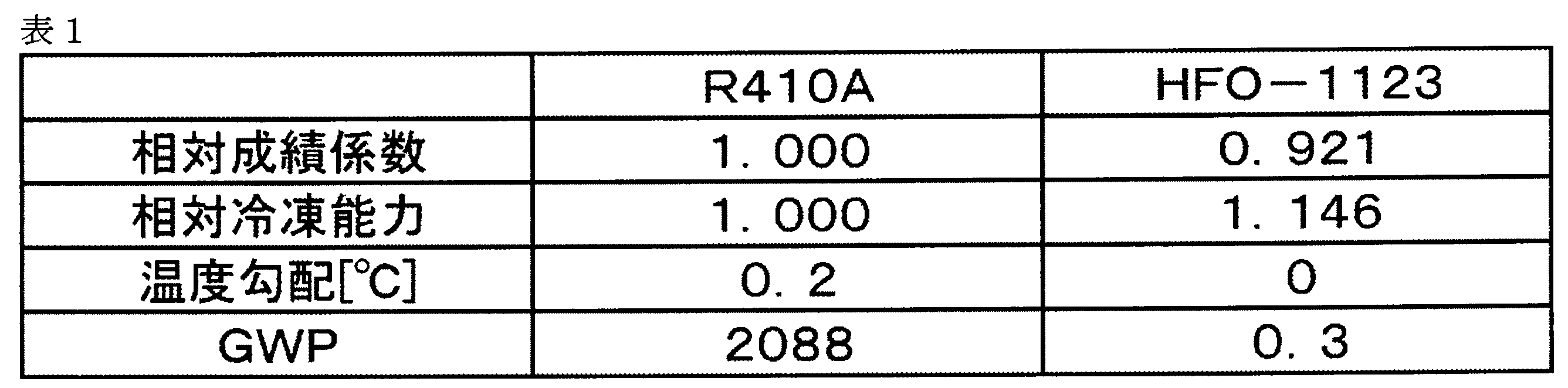
- HFO-1123 as a working medium are shown in Table 1 particularly in a relative comparison with R410A (a pseudo-azeotropic refrigerant mixture having a mass ratio of 1: 1 between HFC-32 and HFC-125).
- the cycle performance is indicated by a coefficient of performance and a refrigerating capacity obtained by a method described later.
- the coefficient of performance and the refrigeration capacity of HFO-1123 are expressed as relative values (hereinafter referred to as the relative coefficient of performance and relative refrigeration capacity) with R410A as the reference (1.000).
- the global warming potential (GWP) is a value of 100 years indicated in the Intergovernmental Panel on climate Change (IPCC) Fourth Assessment Report (2007) or measured according to the method. In this specification, GWP refers to this value unless otherwise specified.
- IPCC Intergovernmental Panel on climate Change
- the working medium used in the present invention preferably contains HFO-1123, and may optionally contain a compound used as a normal working medium in addition to HFO-1123 as long as the effects of the present invention are not impaired.
- a compound used as a normal working medium in addition to HFO-1123 examples include HFO other than HFC and HFO-1123 (HFC having a carbon-carbon double bond), other components that vaporize and liquefy together with HFO-1123 other than these, etc. Is mentioned.
- HFO other than HFC and HFO-1123 HFC having a carbon-carbon double bond
- the working medium contains such a compound in combination with HFO-1123, a better cycle performance can be obtained while keeping the GWP low, and the influence of the temperature gradient is small.
- thermo gradient When the working medium contains, for example, HFO-1123 and an optional component, it has a considerable temperature gradient except when the HFO-1123 and the optional component have an azeotropic composition.
- the temperature gradient of the working medium varies depending on the type of the optional component and the mixing ratio of HFO-1123 and the optional component.
- azeotropic or pseudo-azeotropic mixture such as R410A is preferably used.
- Non-azeotropic compositions have the problem of causing composition changes when filled from a pressure vessel to a refrigeration air conditioner. Furthermore, when refrigerant leakage from the refrigeration air conditioner occurs, the refrigerant composition in the refrigeration air conditioner is very likely to change, and it is difficult to restore the refrigerant composition to the initial state. On the other hand, the above problem can be avoided if the mixture is azeotropic or pseudo-azeotropic.
- Temperature gradient is generally used as an index for measuring the possibility of using the mixture in the working medium.
- a temperature gradient is defined as the nature of heat exchangers, such as evaporation in an evaporator or condensation in a condenser, with different start and end temperatures. In the azeotrope, the temperature gradient is 0, and in the pseudoazeotrope, the temperature gradient is very close to 0, for example, the temperature gradient of R410A is 0.2.
- the inlet temperature in the evaporator decreases, which increases the possibility of frost formation, which is a problem.
- a heat cycle system in order to improve heat exchange efficiency, it is common to make the working medium flowing through the heat exchanger and a heat source fluid such as water or air counter flow, and in a stable operation state Since the temperature difference of the heat source fluid is small, it is difficult to obtain an energy efficient thermal cycle system in the case of a non-azeotropic mixed medium having a large temperature gradient. For this reason, when a mixture is used as a working medium, a working medium having an appropriate temperature gradient is desired.
- HFC The optional HFC is preferably selected from the above viewpoint.
- HFC is known to have higher GWP than HFO-1123. Therefore, the HFC combined with HFO-1123 is appropriately selected from the viewpoint of improving the cycle performance as the working medium and keeping the temperature gradient within an appropriate range, and particularly keeping the GWP within an allowable range. It is preferred that
- an HFC having 1 to 5 carbon atoms is preferable as an HFC that has little influence on the ozone layer and has little influence on global warming.
- the HFC may be linear, branched, or cyclic.
- HFC examples include HFC-32, difluoroethane, trifluoroethane, tetrafluoroethane, HFC-125, pentafluoropropane, hexafluoropropane, heptafluoropropane, pentafluorobutane, heptafluorocyclopentane, and the like.
- HFC 1,1-difluoroethane
- HFC-152a 1,1,1-trifluoroethane
- HFC-125 1,1,2,2-tetrafluoroethane
- HFC-132, HFC -152a, HFC-134a, and HFC-125 are more preferred.
- One HFC may be used alone, or two or more HFCs may be used in combination.
- the content of HFC in the working medium (100% by mass) can be arbitrarily selected according to the required characteristics of the working medium.
- the coefficient of performance and the refrigerating capacity are improved when the content of HFC-32 is in the range of 1 to 99% by mass.
- the coefficient of performance improves when the content of HFC-134a is in the range of 1 to 99% by mass.
- the preferred HFC GWP is 675 for HFC-32, 1430 for HFC-134a and 3500 for HFC-125. From the viewpoint of keeping the GWP of the obtained working medium low, the HFC-32 is most preferable as an optional HFC.
- HFO-1123 and HFC-32 can form a pseudo-azeotropic mixture close to azeotropy in a composition range of 99: 1 to 1:99 by mass ratio. The temperature gradient is close to zero. Also in this respect, HFC-32 is advantageous as an HFC combined with HFO-1123.
- the content of HFC-32 with respect to 100% by mass of the working medium is specifically preferably 20% by mass or more, and 20 to 80% by mass. % Is more preferable, and 40 to 60% by mass is further preferable.
- HFOs other than HFO-1123 may be used alone or in combination of two or more.
- the content of HFO other than HFO-1123 in the working medium (100% by mass) can be arbitrarily selected according to the required characteristics of the working medium.
- the coefficient of performance improves when the content of HFO-1234yf or HFO-1234ze is in the range of 1 to 99% by mass.
- composition range (S) A preferred composition range in the case where the working medium used in the present invention contains HFO-1123 and HFO-1234yf is shown below as a composition range (S).
- the abbreviation of each compound is the ratio (% by mass) of the compound with respect to the total amount of HFO-1123, HFO-1234yf, and other components (HFC-32, etc.). Show.
- the working medium in the composition range (S) has an extremely low GWP and a small temperature gradient.
- refrigeration cycle performance that can be substituted for the conventional R410A can be expressed.
- the ratio of HFO-1123 to the total amount of HFO-1123 and HFO-1234yf is more preferably 40 to 95% by mass, further preferably 50 to 90% by mass, and more preferably 50 to 85% by mass. % Is particularly preferable, and 60 to 85% by mass is most preferable.
- the total content of HFO-1123 and HFO-1234yf in 100% by mass of the working medium is more preferably 80 to 100% by mass, further preferably 90 to 100% by mass, and particularly preferably 95 to 100% by mass.
- the working medium used in the present invention preferably contains HFO-1123, HFC-32, and HFO-1234yf, and a preferred composition range (P) in the case of containing HFO-1123, HFO-1234yf, and HFC-32.
- P a preferred composition range
- the abbreviation of each compound indicates the ratio (mass%) of the compound with respect to the total amount of HFO-1123, HFO-1234yf, and HFC-32.
- R composition range
- L composition range
- M composition range
- the total amount of HFO-1123, HFO-1234yf, and HFC-32 specifically described is more than 90% by mass and less than 100% by mass with respect to the total amount of the working medium for heat cycle. It is preferable that
- the working medium having the above composition is a working medium in which the characteristics of HFO-1123, HFO-1234yf, and HFC-32 are exhibited in a well-balanced manner, and the defects possessed by each are suppressed.
- this working medium is a working medium that has a very low GWP, has a small temperature gradient, and has a certain capacity and efficiency when used in a thermal cycle, and can obtain good cycle performance.
- the total amount of HFO-1123 and HFO-1234yf with respect to the total amount of HFO-1123, HFO-1234yf, and HFC-32 is preferably 70% by mass or more.
- the working medium used in the present invention is more preferably composed of 30 to 70% by mass of HFO-1123 and 4 to 4% of HFO-1234yf with respect to the total amount of HFO-1123, HFO-1234yf, and HFC-32.
- Examples include a composition containing 40% by mass and HFC-32 in a proportion of 0 to 30% by mass, and the content of HFO-1123 with respect to the total amount of the working medium is 70 mol% or less.
- the working medium in the above range is a highly durable working medium in which the above effect is enhanced and the self-decomposition reaction of HFO-1123 is suppressed.
- the content of HFC-32 is preferably 5% by mass or more, and more preferably 8% by mass or more.
- composition range (R) is shown below. ⁇ Composition range (R)> 10% by mass ⁇ HFO-1123 ⁇ 70% by mass 0% by mass ⁇ HFO-1234yf ⁇ 50% by mass 30% by mass ⁇ HFC-32 ⁇ 75% by mass
- the working medium having the above composition is a working medium in which the characteristics of HFO-1123, HFO-1234yf, and HFC-32 are exhibited in a well-balanced manner, and the defects possessed by each are suppressed. That is, it is a working medium in which good cycle performance can be obtained by having a low temperature gradient and high performance and efficiency when used in a thermal cycle after GWP is kept low and durability is ensured.
- composition range (R) preferred ranges are shown below. 20% by mass ⁇ HFO-1123 ⁇ 70% by mass 0% by mass ⁇ HFO-1234yf ⁇ 40% by mass 30% by mass ⁇ HFC-32 ⁇ 75% by mass
- the working medium having the above composition is a working medium in which the characteristics of HFO-1123, HFO-1234yf, and HFC-32 are exhibited in a particularly well-balanced manner, and the defects possessed by each of them are suppressed. That is, it is a working medium in which GWP is kept low and durability is ensured, and when used in a thermal cycle, the temperature gradient is smaller and the cycle performance is higher by having higher capacity and efficiency. is there.
- composition range (R) a more preferred composition range (L) is shown below.
- the composition range (M) is more preferable.
- the working medium having the composition range (M) is a working medium in which the characteristics of the HFO-1123, HFO-1234yf, and HFC-32 are exhibited in a particularly well-balanced manner, and the drawbacks of the working medium are suppressed.
- this working medium has a GWP with an upper limit of 300 or less, and durability is ensured, and when used in a heat cycle, the temperature gradient is less than 5.8, and the relative coefficient of performance and relative This is a working medium having a refrigerating capacity close to 1 and good cycle performance.
- the upper limit of the temperature gradient is lowered, and the lower limit of the relative coefficient of performance x the relative refrigeration capacity is raised. From the viewpoint of a large relative coefficient of performance, 8% by mass ⁇ HFO-1234yf is more preferable. Further, HFO-1234yf ⁇ 35 mass% is more preferable from the viewpoint of high relative refrigeration capacity.
- another working medium used in the present invention preferably contains HFO-1123, HFC-134a, HFC-125, and HFO-1234yf, and the combustibility of the working medium is suppressed by this composition. More preferably, it includes HFO-1123, HFC-134a, HFC-125, and HFO-1234yf, and the ratio of the total amount of HFO-1123, HFC-134a, HFC-125, and HFO-1234yf to the total amount of the working medium is 90%.
- the ratio of HFO-1123 to the total amount of HFO-1123, HFC-134a, HFC-125, and HFO-1234yf is 3% by mass or more and 35% by mass or less, and HFC-134a.
- the ratio of HFC-125 is preferably 4% by mass to 50% by mass, and the ratio of HFO-1234yf is preferably 5% by mass to 50% by mass.
- the working medium is non-flammable and excellent in safety, has less influence on the ozone layer and global warming, and has better cycle performance when used in a thermal cycle system. It can be set as the working medium which has these. Most preferably, it includes HFO-1123, HFC-134a, HFC-125, and HFO-1234yf, and the ratio of the total amount of HFO-1123, HFC-134a, HFC-125, and HFO-1234yf to the total amount of the working medium is 90%.
- the ratio of HFO-1123 to the total amount of HFO-1123, HFC-134a, HFC-125, and HFO-1234yf is 6 mass% or more and 25 mass% or less, and HFC-134a. It is even more preferable that the ratio of HFC-125 is 20% by mass to 35% by mass, the ratio of HFC-125 is 8% by mass to 30% by mass, and the ratio of HFO-1234yf is 20% by mass to 50% by mass.
- the working medium is non-flammable, and is more excellent in safety, has less influence on the ozone layer and global warming, and is even better when used in a heat cycle system.
- the working medium having a high cycle performance can be obtained.
- the working medium used in the composition for a heat cycle system of the present invention may contain carbon dioxide, hydrocarbon, chlorofluoroolefin (CFO), hydrochlorofluoroolefin (HCFO) and the like in addition to the above optional components.
- CFO chlorofluoroolefin
- HCFO hydrochlorofluoroolefin
- Other optional components are preferably components that have little influence on the ozone layer and little influence on global warming.
- hydrocarbon examples include propane, propylene, cyclopropane, butane, isobutane, pentane, isopentane and the like.
- a hydrocarbon may be used individually by 1 type and may be used in combination of 2 or more type.
- the working medium contains a hydrocarbon
- the content thereof is less than 10% by weight with respect to 100% by weight of the working medium, preferably 1 to 5% by weight, and more preferably 3 to 5% by weight. If a hydrocarbon is more than a lower limit, the solubility of the mineral refrigeration oil to a working medium will become more favorable.
- CFO examples include chlorofluoropropene and chlorofluoroethylene.
- CFO 1,1-dichloro-2,3,3,3-tetrafluoropropene (CFO-1214ya), 1 is easy to suppress the flammability of the working medium without greatly reducing the cycle performance of the working medium.
- CFO-1214yb 3-dichloro-1,2,3,3-tetrafluoropropene (CFO-1214yb) and 1,2-dichloro-1,2-difluoroethylene (CFO-1112) are preferred.
- One type of CFO may be used alone, or two or more types may be used in combination.
- the working medium contains CFO
- the content thereof is less than 10% by weight with respect to 100% by weight of the working medium, preferably 1 to 8% by weight, and more preferably 2 to 5% by weight. If the CFO content is at least the lower limit value, it is easy to suppress the combustibility of the working medium. If the content of CFO is not more than the upper limit value, good cycle performance can be easily obtained.
- HCFO examples include hydrochlorofluoropropene and hydrochlorofluoroethylene.
- HCFO 1-chloro-2,3,3,3-tetrafluoropropene (HCFO-1224yd)
- 1-chloro can be used because flammability of the working medium can be easily suppressed without greatly reducing the cycle performance of the working medium.
- -1,2-difluoroethylene (HCFO-1122) is preferred.
- HCFO may be used alone or in combination of two or more.
- the content of HCFO in 100% by mass of the working medium is less than 10% by mass, preferably 1 to 8% by mass, and more preferably 2 to 5% by mass. If the content of HCFO is equal to or higher than the lower limit value, it is easy to suppress the combustibility of the working medium. If the content of HCFO is not more than the upper limit value, good cycle performance can be easily obtained.
- the total content of other optional components in the working medium is less than 10% by mass with respect to 100% by mass of the working medium, and 8% by mass. % Or less is preferable, and 5 mass% or less is more preferable.
- FIG. 1 is a diagram showing a schematic configuration of a refrigeration cycle apparatus 1 according to the present embodiment.
- the refrigeration cycle apparatus 1 includes a compressor 10, a condenser 12, an expansion mechanism 13, and an evaporator 14.
- the compressor 10 compresses the working medium (steam).
- the condenser 12 cools the vapor of the working medium discharged from the compressor 10 into a liquid.
- the expansion mechanism 13 expands the working medium (liquid) discharged from the condenser 12.
- the evaporator 14 heats the working medium (liquid) discharged from the expansion mechanism 13 to generate steam.
- the evaporator 14 and the condenser 12 are configured to exchange heat between the working medium and a heat source fluid that flows opposite or in parallel.
- the refrigeration cycle apparatus 1 further includes a fluid supply means 15 for supplying a heat source fluid E such as water or air to the evaporator 14, a fluid supply means 16 for supplying a heat source fluid F such as water or air to the condenser 12, It has.
- emitted from the evaporator 14 is compressed with the compressor 10, and it is set as the high temperature / high pressure working medium vapor
- emitted from the compressor 10 is cooled with the fluid F in the condenser 12, and is liquefied, and is set as the working-medium liquid C.
- the fluid F is heated to become a fluid F ′ and discharged from the condenser 12.
- the working medium liquid C discharged from the condenser 12 is expanded by the expansion mechanism 13 to obtain a low temperature and low pressure working medium liquid D.
- the working medium liquid D discharged from the expansion mechanism 13 is heated by the fluid E in the evaporator 14 to form working medium vapor A.
- the fluid E is cooled to become a fluid E ′ and is discharged from the evaporator 14.
- FIG. 2 is a pressure-enthalpy diagram showing a change in the state of the working medium of the refrigeration cycle apparatus 1.
- adiabatic compression is performed by the compressor 10, and the low-temperature and low-pressure working medium vapor A is changed to high-temperature and high-pressure working medium vapor B.
- isobaric cooling is performed by the condenser 12, and the working medium vapor B is used as the working medium liquid C.
- the expansion mechanism 13 performs isenthalpy expansion, and the high-temperature and high-pressure working medium liquid C is used as the low-temperature and low-pressure working medium liquid D.
- the evaporator 14 performs isobaric heating to return the working medium liquid D to the working medium vapor A.
- FIG. 3 is a longitudinal sectional view showing a schematic configuration of the compressor 10. 4 is a cross-sectional view taken along the line IV-IV in FIG.
- a rotary compressor will be described as an example.
- the compressor 10 includes a casing 81, a compression means 30 that compresses a low-temperature and low-pressure working medium (gas) sucked from an accumulator 83 through a suction pipe 82, and a compression means 30.
- Driving means 20 for driving the As shown in FIG. 3, in the internal space of the casing 81, the driving means 20 is disposed on the upper side, and the compression means 30 is disposed on the lower side. The driving force of the driving unit 20 is transmitted to the compression unit 30 through the driving shaft 50.
- the compression means 30 includes a roller 31, a cylinder 32, an upper closing member 40, and a lower closing member 60.
- the roller 31 is disposed in the cylinder 32.
- a compression chamber 33 is formed between the inner peripheral surface of the cylinder 32 and the roller 31.
- the compression chamber 33 is divided into two compression chambers 33 a and 33 b by a vane 34.
- One end of the vane 34 is biased to the outer periphery of the roller 31 by biasing means such as a spring provided at the other end of the vane 34.
- the driving means 20 is, for example, a three-phase dielectric motor, and includes a stator 21 and a rotor 22.
- the stator 21 is fixed in contact with the inner peripheral surface of the casing 81.
- the stator 21 has an iron core and a winding wound around the iron core via an insulating member.
- the rotor 22 is installed inside the stator 21 via a certain gap.
- the rotor 22 has an iron core and a permanent magnet.
- a power supply terminal 71 for supplying electric power from the outside of the compressor 10 to the inside of the upper portion of the casing 81 is attached. Electric power is supplied to the stator 21 of the driving means 20 from the power supply terminal 71 via the lead wire portion 72. Thereby, the rotor 22 of the drive means 20 rotates, and the drive shaft 50 fixed to the rotor 22 rotates the roller 31 of the compression means 30.
- the lead wire portion 72 has lead wires 73 a, 73 b, 73 c and a connector (cluster block) 77.
- the lead wires 73a, 73b, and 73c electrically connect the driving unit 20 and the power supply terminal 71.
- the connection between the power supply terminal 71 and the lead wires 73a, 73b, 73c is made through a connector 77. Details of the configuration of the lead wire portion 72 will be described later.
- the working medium in the compression chamber 33 is compressed by the roller 31 being rotationally driven in the compression chamber 33.
- the upper closing member 40 is provided with a discharge valve.
- the working refrigerant that has been compressed in the compression chamber 33 to a high temperature and high pressure is discharged from the discharge pipe 84 through the discharge valve.
- the refrigeration cycle apparatus 1 uses a working medium including HFO-1123.
- HFO-1123 when a constant ignition energy is applied in a high temperature and high pressure state, a chemical reaction accompanied by heat generation called a disproportionation reaction (self-decomposition reaction) may occur in a chain.
- a disproportionation reaction is a chemical reaction in which two or more of the same type of molecule react with each other to produce two or more different types of products. When such a disproportionation reaction occurs in the refrigeration cycle apparatus, a rapid temperature increase and pressure increase occur, and the reliability of the refrigeration cycle apparatus is impaired.
- a place where a constant ignition energy is likely to be given to the working medium under high temperature and high pressure is mainly inside the compressor 10.
- the compressor 10 shown in FIG. 3 one of the parts where ignition energy may be applied to the working medium under high temperature and high pressure is a short-circuit between the electrical components (lead wire portion 72).
- FIG. 5 is a diagram for explaining a general configuration of the lead wire portion 972 in the compressor used in the existing refrigeration cycle apparatus.
- the lead wire portion 972 includes lead wires 73 a, 73 b, 73 c and a connector 77.
- Insertion terminals 78a, 78b, and 78c are attached to the leading ends of the lead wires 73a, 73b, and 73c.
- the insertion terminals 78a, 78b, and 78c are covered with a connector 77 formed of resin.
- the connector 77 is formed with terminal insertion holes 77a, 77b, 77c.
- the lead wires 73a, 73b, and 73c are inserted into the connector 77 so that the distal ends of the insertion terminals 78a, 78b, and 78c are respectively positioned at the terminal insertion holes 77a, 77b, and 77c.
- Each terminal of the power supply terminal 71 (see FIG. 3) is inserted into the terminal insertion holes 77a, 77b, and 77c.
- the lead wires 73a, 73b, and 73c are bound by a binding member 74 such as a transparent tube at an intermediate portion.
- the reason for bundling the lead wires 73a, 73b, 73c is mainly to improve workability and to prevent the lead wires from contacting and damaging the sliding portions of the compressor.
- the lead wires 73a, 73b, 73c have different voltage phases and a large potential difference between the lead wires. For this reason, if the covering of the lead wires is damaged for some reason at the portion where the lead wires 73a, 73b, 73c are bundled by the bundling member 74, the lead wires are short-circuited and discharge (spark) occurs. Damage to the lead wire coating can occur, for example, when the lead wire coating melts due to abnormal energization of the compressor. During operation of the refrigeration cycle apparatus, the lead wire portion 972 is exposed to the atmosphere of the working medium that has become high temperature and pressure.
- HFO-1123 When a working medium including HFO-1123 is used as the working medium of the refrigeration cycle apparatus, when the lead wires 73a, 73b, and 73c are short-circuited and discharge occurs, ignition energy is given to the working medium under high temperature and high pressure, and HFO is supplied. -1123 may occur. In order to suppress the occurrence of the disproportionation reaction of HFO-1123, it is necessary to suppress the discharge due to the short circuit of the lead wire portion 972.
- FIG. 6 is a diagram illustrating a schematic configuration of the lead wire portion 72 in the compressor 10 of the refrigeration cycle apparatus 1 according to the present embodiment.
- symbol is attached
- the lead wires 73a, 73b, 73c are bundled by a bundling member 74 such as a transparent tube at an intermediate portion.
- the lead wires 73a, 73b, and 73c are covered with an insulating material 75 having heat resistance of 300 ° C. or higher at the portion bound by the binding member 74, respectively.
- the portions of the lead wires 73a, 73b, and 73c that are bundled by the bundling member 74 are respectively covered with the insulating material 75 having heat resistance of 300 ° C. or higher, the portions of the bundled portions of the lead wires 73a, 73b, and 73c Even if the coating melts due to abnormal energization of the compressor, the lead wires 73a, 73b, 73c can be prevented from being short-circuited and causing discharge. Thereby, when a working medium containing HFO-1123 is used, the occurrence of a disproportionation reaction of HFO-1123 can be effectively suppressed.
- Embodiment 2 Embodiment 2 of the present invention will be described below with reference to the drawings.
- the refrigeration cycle apparatus of the present embodiment is the same as the refrigeration cycle apparatus 1 described in the first embodiment with reference to FIG. Further, the schematic configuration of the compressor used in the refrigeration cycle apparatus of the present embodiment is basically the same as the compressor 10 described in the first embodiment with reference to FIG. The difference from the compressor 10 of Embodiment 1 is the configuration of the lead wire portion.
- FIG. 7 is a diagram for explaining a schematic configuration of the lead wire portion 172 in the present embodiment. Components common to the lead wire portion 72 in the first embodiment shown in FIG. 6 are denoted by the same reference numerals and description thereof is omitted. As shown in FIG. 7, the lead wires 73a, 73b, and 73c are bound by an insulating member 176 having heat resistance of 300 ° C. or higher at the intermediate portion.
- FIG. 8 is a perspective view showing the external appearance of the insulating member 176.
- FIG. 9 is a top view of the insulating member 176.
- the cylindrical insulating member 176 there are the same number (three) of through holes 176a, 176b, 176c as the number of lead wires 73a, 73b, 73c (three). Is formed.
- the diameters of the through holes 176a, 176b, and 176c are set such that one lead wire can pass through.
- the plurality of through holes 176a, 176b, and 176c formed in the insulating member 176 are spaced apart from each other by a predetermined distance d.
- a part of the plurality of lead wires 73a, 73b, 73c is arranged to pass through different through holes. That is, a part of the lead wire 73a is arranged to pass through the through hole 176a, a part of the lead wire 73b is passed through the through hole 176b, and a part of the lead wire 73c is arranged to pass through the through hole 176c.
- the insulation members 176 bundle the lead wires 73a, 73b, 73c so that the distances between the lead wires are not in contact with each other, so that the coating of the lead wires 73a, 73b, 73c is melted due to abnormal energization of the compressor.
- the shape of the insulating member 176 is not limited to the cylindrical shape, and may be, for example, a spherical shape. Further, the number of insulating members 176 attached to the lead wires 73a, 73b, 73c is not limited to one as long as the distance between the lead wires can be separated by a distance that does not contact each other. There may be.
- Embodiment 3 Embodiment 3 of the present invention will be described below with reference to the drawings.
- the refrigeration cycle apparatus of the present embodiment is the same as the refrigeration cycle apparatus 1 described in the first embodiment with reference to FIG. Further, the schematic configuration of the compressor used in the refrigeration cycle apparatus of the present embodiment is basically the same as the compressor 10 described in the first embodiment with reference to FIG. The difference from the compressor 10 of Embodiment 1 is the configuration of the lead wire portion.
- the connector 77 is formed of a resin having insufficient heat resistance. It has been experimentally confirmed that when the compressor is abnormally energized, in the lead wire portion 972, the connector 77 may dissolve before the coating of the lead wires 73a, 73b, 73c dissolves. When the connector 77 is melted, the plug terminals 78a, 78b, and 78c attached to the tips of the lead wires 73a, 73b, and 73c may come into contact with each other to cause discharge.
- the refrigeration cycle apparatus 1 uses a working medium including HFO-1123.
- a working medium including HFO-1123.
- ignition energy is given to the working medium under high temperature and high pressure in the compressor 10 shown in FIG. May cause a disproportionation reaction of HFO-1123.
- FIG. 10 is a diagram illustrating a schematic configuration of the lead wire portion 272 in the present embodiment.
- symbol is attached
- the configuration of the connector 277 is basically the same as the configuration of the connector 77 shown in FIG. 5 (the terminal insertion holes 277a, 277b, 277c of the connector 277 correspond to the terminal insertion holes 77a, 77b, 77c of the connector 77), Only the material is different.
- the connector 277 is formed of an insulating material having heat resistance of 300 ° C. or higher.
- Examples of the material of the connector 277 include wire materials whose heat resistance classes defined in JIS C4003 are 180 (H), 200 (N), 220 (R), and 250.
- examples of the main material include materials having high heat resistance such as mica, asbestos (asbestos), alumina, silica glass, quartz, magnesium oxide, polytetrafluoroethylene, and silicon rubber.
- Polyimide resin, polybenzimidazole resin, polyetheretherketone resin, polyphenylene sulfide resin, nylon resin, polybutylene terephthalate resin, polyetherimide resin, polyamideimide resin, allyl resin, diallyl phthalate resin, acetylcellulose resin, acetic acid A cellulose resin etc. are mentioned. These heat resistant materials may be used alone or in combination of two or more in order to impart good heat resistance.
- silicon resin can be used as an impregnation coating material or an insulation treatment material used when manufacturing a heat-resistant material electric wire.
- the impregnating coating material and the insulating treatment material are used in combination with the heat-resistant material to develop auxiliary functions such as an improvement in insulation.
- Embodiment 4 of the present invention will be described below with reference to the drawings.
- the refrigeration cycle apparatus of the present embodiment is the same as the refrigeration cycle apparatus 1 described in the first embodiment with reference to FIG. Further, the schematic configuration of the compressor used in the refrigeration cycle apparatus of the present embodiment is basically the same as the compressor 10 described in the first embodiment with reference to FIG. The difference from the compressor 10 of Embodiment 1 is the configuration of the lead wire portion.
- FIG. 11 is an enlarged view of the peripheral portion of the connector 77 in the lead wire portion 972 of the compressor used in the existing refrigeration cycle apparatus shown in FIG.
- lead wires 73 a, 73 b, 73 c are inserted into the connector 77 in parallel with each other. If the lead wires 73a, 73b, 73c are inserted into the connector 77 in parallel with each other, the distance between the respective insertion terminals 78a, 78b, 78c is reduced, so that the connector 77 is melted due to abnormal energization of the compressor. In some cases, the plug terminals 78a, 78b, and 78c may come into contact with each other to cause discharge.
- the refrigeration cycle apparatus 1 uses a working medium including HFO-1123.
- a working medium including HFO-1123.
- ignition energy is given to the working medium under high temperature and high pressure in the compressor 10 shown in FIG. May cause a disproportionation reaction of HFO-1123.
- FIG. 12 is an enlarged view of the peripheral portion of the connector 377 of the lead wire portion 372 in the present embodiment.
- lead wires 73a, 73b, and 73c are inserted into the connector 377 at angles in directions away from each other. Specifically, the lead wire 73a and the lead wire 73b are inserted with an angle ⁇ in directions away from each other.
- the lead wire 73b and the lead wire 73c are inserted with an angle ⁇ in directions away from each other.
- the angles ⁇ and ⁇ are preferably 90 degrees or less from the viewpoint of workability and prevention of winding of the lead wire into the compressor sliding portion.
- the distance between the plug-in terminals can be increased, so that the leading ends of the lead wires 73a, 73b, and 73c can be separated. It can suppress that the insertion terminals 78a, 78b, and 78c contact each other and discharge. Thereby, when a working medium containing HFO-1123 is used, the occurrence of a disproportionation reaction of HFO-1123 can be effectively suppressed.
- the compressor of the refrigeration cycle apparatus has been described as a rotary compressor.
- the present invention is not limited to this, and for example, a scroll compressor may be used.
- the motor of the driving means in the compressor is a three-phase dielectric motor in the above-described embodiment, but may be a brushless DC (Direct Current) motor, for example.
- each embodiment can be appropriately combined.
- Embodiment 3 and Embodiment 4 can be combined with Embodiment 1.
- Embodiment 3 and Embodiment 4 can be combined with Embodiment 2.
Abstract
Description
以下、本発明の実施の形態1について、図面を参照しながら説明する。
<作動媒体>
(HFO-1123)
本発明で用いる作動媒体は1,1,2-トリフルオロエチレン(HFO-1123)を含む。 First, the working medium used for the refrigeration cycle apparatus of the present invention will be described.
<Working medium>
(HFO-1123)
The working medium used in the present invention includes 1,1,2-trifluoroethylene (HFO-1123).
HFO-1123の作動媒体としての特性を、特に、R410A(HFC-32とHFC-125の質量比1:1の擬似共沸混合冷媒)との相対比較において表1に示す。サイクル性能は、後述する方法で求められる成績係数と冷凍能力とで示される。HFO-1123の成績係数と冷凍能力とは、R410Aを基準(1.000)とした相対値(以下、相対成績係数および相対冷凍能力という)で示す。地球温暖化係数(GWP)は、気候変動に関する政府間パネル(IPCC)第4次評価報告書(2007年)に示される、または該方法に準じて測定された100年の値である。本明細書において、GWPは特に断りのない限りこの値をいう。作動媒体が混合物からなる場合、後述するとおり温度勾配は、作動媒体を評価する上で重要なファクターとなり、値は小さい方が好ましい。 First, the working medium used for the refrigeration cycle apparatus of the present invention will be described.
The characteristics of HFO-1123 as a working medium are shown in Table 1 particularly in a relative comparison with R410A (a pseudo-azeotropic refrigerant mixture having a mass ratio of 1: 1 between HFC-32 and HFC-125). The cycle performance is indicated by a coefficient of performance and a refrigerating capacity obtained by a method described later. The coefficient of performance and the refrigeration capacity of HFO-1123 are expressed as relative values (hereinafter referred to as the relative coefficient of performance and relative refrigeration capacity) with R410A as the reference (1.000). The global warming potential (GWP) is a value of 100 years indicated in the Intergovernmental Panel on Climate Change (IPCC) Fourth Assessment Report (2007) or measured according to the method. In this specification, GWP refers to this value unless otherwise specified. When the working medium is composed of a mixture, the temperature gradient is an important factor in evaluating the working medium as described later, and a smaller value is preferable.
本発明で用いる作動媒体はHFO-1123を含むことが好ましく、本発明の効果を損なわない範囲でHFO-1123以外に、通常作動媒体として用いられる化合物を任意に含有してもよい。このような任意の化合物(任意成分)としては、例えば、HFC、HFO-1123以外のHFO(炭素-炭素二重結合を有するHFC)、これら以外のHFO-1123とともに気化、液化する他の成分等が挙げられる。任意成分としては、HFC、HFO-1123以外のHFO(炭素-炭素二重結合を有するHFC)が好ましい。 [Optional ingredients]
The working medium used in the present invention preferably contains HFO-1123, and may optionally contain a compound used as a normal working medium in addition to HFO-1123 as long as the effects of the present invention are not impaired. Examples of such an arbitrary compound (optional component) include HFO other than HFC and HFO-1123 (HFC having a carbon-carbon double bond), other components that vaporize and liquefy together with HFO-1123 other than these, etc. Is mentioned. As an optional component, HFO other than HFC and HFO-1123 (HFC having a carbon-carbon double bond) is preferable.
作動媒体が例えばHFO-1123と任意成分とを含有する場合、HFO-1123と任意成分とが共沸組成である場合を除いて相当の温度勾配を有する。作動媒体の温度勾配は、任意成分の種類およびHFO-1123と任意成分との混合割合により異なる。 (Temperature gradient)
When the working medium contains, for example, HFO-1123 and an optional component, it has a considerable temperature gradient except when the HFO-1123 and the optional component have an azeotropic composition. The temperature gradient of the working medium varies depending on the type of the optional component and the mixing ratio of HFO-1123 and the optional component.
任意成分のHFCとしては、上記観点から選択されることが好ましい。ここで、HFCは、HFO-1123に比べてGWPが高いことが知られている。したがって、HFO-1123と組合せるHFCとしては、上記作動媒体としてのサイクル性能を向上させ、かつ温度勾配を適切な範囲にとどめることに加えて、特にGWPを許容の範囲にとどめる観点から、適宜選択されることが好ましい。 (HFC)
The optional HFC is preferably selected from the above viewpoint. Here, HFC is known to have higher GWP than HFO-1123. Therefore, the HFC combined with HFO-1123 is appropriately selected from the viewpoint of improving the cycle performance as the working medium and keeping the temperature gradient within an appropriate range, and particularly keeping the GWP within an allowable range. It is preferred that
HFCは、1種を単独で用いてもよく、2種以上を組み合わせて用いてもよい。 Among them, as HFC, HFC-32, 1,1-difluoroethane (HFC-152a), 1,1,1-trifluoroethane (HFC) have little influence on the ozone layer and have excellent refrigeration cycle characteristics. -143a), 1,1,2,2-tetrafluoroethane (HFC-134), 1,1,1,2-tetrafluoroethane (HFC-134a), and HFC-125 are preferred, HFC-32, HFC -152a, HFC-134a, and HFC-125 are more preferred.
One HFC may be used alone, or two or more HFCs may be used in combination.
なお、組成範囲(S)を示す各式において、各化合物の略称は、HFO-1123とHFO-1234yfとその他の成分(HFC-32等)との合計量に対する当該化合物の割合(質量%)を示す。 A preferred composition range in the case where the working medium used in the present invention contains HFO-1123 and HFO-1234yf is shown below as a composition range (S).
In each formula showing the composition range (S), the abbreviation of each compound is the ratio (% by mass) of the compound with respect to the total amount of HFO-1123, HFO-1234yf, and other components (HFC-32, etc.). Show.
HFO-1123+HFO-1234yf≧70質量%
95質量%≧HFO-1123/(HFO-1123+HFO-1234yf)≧35質量% <Composition range (S)>
HFO-1123 + HFO-1234yf ≧ 70% by mass
95% by mass ≧ HFO-1123 / (HFO-1123 + HFO-1234yf) ≧ 35% by mass
なお、組成範囲(P)を示す各式において、各化合物の略称は、HFO-1123とHFO-1234yfとHFC-32との合計量に対する当該化合物の割合(質量%)を示す。組成範囲(R)、組成範囲(L)、組成範囲(M)においても同様である。また、以下に記載の組成範囲では、具体的に記載したHFO-1123とHFO-1234yfとHFC-32との合計量が、熱サイクル用作動媒体全量に対して90質量%を超え100質量%以下であることが好ましい。 The working medium used in the present invention preferably contains HFO-1123, HFC-32, and HFO-1234yf, and a preferred composition range (P) in the case of containing HFO-1123, HFO-1234yf, and HFC-32. Is shown below.
Note that, in each formula showing the composition range (P), the abbreviation of each compound indicates the ratio (mass%) of the compound with respect to the total amount of HFO-1123, HFO-1234yf, and HFC-32. The same applies to the composition range (R), composition range (L), and composition range (M). In the composition range described below, the total amount of HFO-1123, HFO-1234yf, and HFC-32 specifically described is more than 90% by mass and less than 100% by mass with respect to the total amount of the working medium for heat cycle. It is preferable that
70質量%≦HFO-1123+HFO-1234yf
30質量%≦HFO-1123≦80質量%
0質量%<HFO-1234yf≦40質量%
0質量%<HFC-32≦30質量%
HFO-1123/HFO-1234yf≦95/5質量% <Composition range (P)>
70 mass% ≦ HFO-1123 + HFO-1234yf
30% by mass ≦ HFO-1123 ≦ 80% by mass
0% by mass <HFO-1234yf ≦ 40% by mass
0% by mass <HFC-32 ≦ 30% by mass
HFO-1123 / HFO-1234yf ≦ 95/5% by mass
さらに好ましい組成範囲(R)を、以下に示す。
<組成範囲(R)>
10質量%≦HFO-1123<70質量%
0質量%<HFO-1234yf≦50質量%
30質量%<HFC-32≦75質量% Further, another preferred composition is shown when the working medium used in the present invention contains HFO-1123, HFO-1234yf, and HFC-32. For example, the self-decomposition reaction of HFO-1123 is suppressed, and a highly durable working medium can be obtained.
A more preferred composition range (R) is shown below.
<Composition range (R)>
10% by mass ≦ HFO-1123 <70% by mass
0% by mass <HFO-1234yf ≦ 50% by mass
30% by mass <HFC-32 ≦ 75% by mass
20質量%≦HFO-1123<70質量%
0質量%<HFO-1234yf≦40質量%
30質量%<HFC-32≦75質量% In the working medium of the present invention having the composition range (R), preferred ranges are shown below.
20% by mass ≦ HFO-1123 <70% by mass
0% by mass <HFO-1234yf ≦ 40% by mass
30% by mass <HFC-32 ≦ 75% by mass
<組成範囲(L)>
10質量%≦HFO-1123<70質量%
0質量%<HFO-1234yf≦50質量%
30質量%<HFC-32≦44質量% In the working medium of the present invention having the composition range (R), a more preferred composition range (L) is shown below. The composition range (M) is more preferable.
<Composition range (L)>
10% by mass ≦ HFO-1123 <70% by mass
0% by mass <HFO-1234yf ≦ 50% by mass
30% by mass <HFC-32 ≦ 44% by mass
20質量%≦HFO-1123<70質量%
5質量%≦HFO-1234yf≦40質量%
30質量%<HFC-32≦44質量% <Composition range (M)>
20% by mass ≦ HFO-1123 <70% by mass
5% by mass ≦ HFO-1234yf ≦ 40% by mass
30% by mass <HFC-32 ≦ 44% by mass
この範囲にあると温度勾配の上限が下がり、相対成績係数×相対冷凍能力の下限が上がる。相対成績係数が大きい点から8質量%≦HFO-1234yfがより好ましい。また、相対冷凍能力が大きい点からHFO-1234yf≦35質量%がより好ましい。 The working medium having the composition range (M) is a working medium in which the characteristics of the HFO-1123, HFO-1234yf, and HFC-32 are exhibited in a particularly well-balanced manner, and the drawbacks of the working medium are suppressed. In other words, this working medium has a GWP with an upper limit of 300 or less, and durability is ensured, and when used in a heat cycle, the temperature gradient is less than 5.8, and the relative coefficient of performance and relative This is a working medium having a refrigerating capacity close to 1 and good cycle performance.
Within this range, the upper limit of the temperature gradient is lowered, and the lower limit of the relative coefficient of performance x the relative refrigeration capacity is raised. From the viewpoint of a large relative coefficient of performance, 8% by mass ≦ HFO-1234yf is more preferable. Further, HFO-1234yf ≦ 35 mass% is more preferable from the viewpoint of high relative refrigeration capacity.
さらに好ましくは、HFO-1123とHFC-134aとHFC-125とHFO-1234yfとを含み、作動媒体全量に対するHFO-1123とHFC-134aとHFC-125とHFO-1234yfとの合計量の割合が90質量%を超え100質量%以下であり、HFO-1123とHFC-134aとHFC-125とHFO-1234yfとの合計量に対する、HFO-1123の割合が3質量%以上35質量%以下、HFC-134aの割合が10質量%以上53質量%以下、HFC-125の割合が4質量%以上50質量%以下、HFO-1234yfの割合が5質量%以上50質量%以下であることが好ましい。このような作動媒体とすることにより、作動媒体が不燃性であり、かつ安全性に優れ、オゾン層および地球温暖化への影響をより少なくし、熱サイクルシステムに用いた際により優れたサイクル性能を有する作動媒体とすることができる。
最も好ましくは、HFO-1123とHFC-134aとHFC-125とHFO-1234yfとを含み、作動媒体全量に対するHFO-1123とHFC-134aとHFC-125とHFO-1234yfとの合計量の割合が90質量%を超え100質量%以下であり、HFO-1123とHFC-134aとHFC-125とHFO-1234yfとの合計量に対する、HFO-1123の割合が6質量%以上25質量%以下、HFC-134aの割合が20質量%以上35質量%以下、HFC-125の割合が8質量%以上30質量%以下、HFO-1234yfの割合が20質量%以上50質量%以下であることがより一層好ましい。このような作動媒体とすることにより、作動媒体が不燃性であり、かつ安全性により一層優れ、オゾン層および地球温暖化への影響をより一層少なくし、熱サイクルシステムに用いた際により一層優れたサイクル性能を有する作動媒体とすることができる。 Further, another working medium used in the present invention preferably contains HFO-1123, HFC-134a, HFC-125, and HFO-1234yf, and the combustibility of the working medium is suppressed by this composition.
More preferably, it includes HFO-1123, HFC-134a, HFC-125, and HFO-1234yf, and the ratio of the total amount of HFO-1123, HFC-134a, HFC-125, and HFO-1234yf to the total amount of the working medium is 90%. The ratio of HFO-1123 to the total amount of HFO-1123, HFC-134a, HFC-125, and HFO-1234yf is 3% by mass or more and 35% by mass or less, and HFC-134a. The ratio of HFC-125 is preferably 4% by mass to 50% by mass, and the ratio of HFO-1234yf is preferably 5% by mass to 50% by mass. By using such a working medium, the working medium is non-flammable and excellent in safety, has less influence on the ozone layer and global warming, and has better cycle performance when used in a thermal cycle system. It can be set as the working medium which has these.
Most preferably, it includes HFO-1123, HFC-134a, HFC-125, and HFO-1234yf, and the ratio of the total amount of HFO-1123, HFC-134a, HFC-125, and HFO-1234yf to the total amount of the working medium is 90%. The ratio of HFO-1123 to the total amount of HFO-1123, HFC-134a, HFC-125, and HFO-1234yf is 6 mass% or more and 25 mass% or less, and HFC-134a. It is even more preferable that the ratio of HFC-125 is 20% by mass to 35% by mass, the ratio of HFC-125 is 8% by mass to 30% by mass, and the ratio of HFO-1234yf is 20% by mass to 50% by mass. By using such a working medium, the working medium is non-flammable, and is more excellent in safety, has less influence on the ozone layer and global warming, and is even better when used in a heat cycle system. The working medium having a high cycle performance can be obtained.
本発明の熱サイクルシステム用組成物に用いる作動媒体は、上記任意成分以外に、二酸化炭素、炭化水素、クロロフルオロオレフィン(CFO)、ヒドロクロロフルオロオレフィン(HCFO)等を含有してもよい。その他の任意成分としてはオゾン層への影響が少なく、かつ地球温暖化への影響が小さい成分が好ましい。 (Other optional ingredients)
The working medium used in the composition for a heat cycle system of the present invention may contain carbon dioxide, hydrocarbon, chlorofluoroolefin (CFO), hydrochlorofluoroolefin (HCFO) and the like in addition to the above optional components. Other optional components are preferably components that have little influence on the ozone layer and little influence on global warming.
炭化水素は、1種を単独で用いてもよく、2種以上を組み合わせて用いてもよい。 Examples of the hydrocarbon include propane, propylene, cyclopropane, butane, isobutane, pentane, isopentane and the like.
A hydrocarbon may be used individually by 1 type and may be used in combination of 2 or more type.
CFOは、1種を単独で用いてもよく、2種以上を組み合わせて用いてもよい。 Examples of CFO include chlorofluoropropene and chlorofluoroethylene. As CFO, 1,1-dichloro-2,3,3,3-tetrafluoropropene (CFO-1214ya), 1 is easy to suppress the flammability of the working medium without greatly reducing the cycle performance of the working medium. , 3-dichloro-1,2,3,3-tetrafluoropropene (CFO-1214yb) and 1,2-dichloro-1,2-difluoroethylene (CFO-1112) are preferred.
One type of CFO may be used alone, or two or more types may be used in combination.
HCFOは、1種を単独で用いてもよく、2種以上を組み合わせて用いてもよい。 Examples of HCFO include hydrochlorofluoropropene and hydrochlorofluoroethylene. As HCFO, 1-chloro-2,3,3,3-tetrafluoropropene (HCFO-1224yd), 1-chloro can be used because flammability of the working medium can be easily suppressed without greatly reducing the cycle performance of the working medium. -1,2-difluoroethylene (HCFO-1122) is preferred.
HCFO may be used alone or in combination of two or more.
次に、本実施の形態にかかる冷凍サイクル装置の概略構成について説明する。
図1は、本実施の形態にかかる冷凍サイクル装置1の概略構成を示す図である。冷凍サイクル装置1は、圧縮機10と、凝縮器12と、膨張機構13と、蒸発器14と、を備えている。圧縮機10は、作動媒体(蒸気)を圧縮する。凝縮器12は、圧縮機10から排出された作動媒体の蒸気を冷却し液体とする。膨張機構13は、凝縮器12から排出された作動媒体(液体)を膨張させる。蒸発器14は、膨張機構13から排出された作動媒体(液体)を加熱して蒸気とする。蒸発器14および凝縮器12は、作動媒体と対向または並行して流れる熱源流体との間で熱交換を行うように構成されている。冷凍サイクル装置1は、さらに、蒸発器14に水や空気などの熱源流体Eを供給する流体供給手段15と、凝縮器12に水や空気などの熱源流体Fを供給する流体供給手段16と、を備えている。 <Configuration of refrigeration cycle apparatus>
Next, a schematic configuration of the refrigeration cycle apparatus according to the present embodiment will be described.
FIG. 1 is a diagram showing a schematic configuration of a
そして、圧縮機10から排出された作動媒体蒸気Bを凝縮器12にて流体Fによって冷却し、液化して作動媒体液Cとする。この際、流体Fは加熱されて流体F’となり、凝縮器12から排出される。続いて、凝縮器12から排出された作動媒体液Cを膨張機構13にて膨張させて低温低圧の作動媒体液Dとする。続いて、膨張機構13から排出された作動媒体液Dを蒸発器14にて流体Eによって加熱して作動媒体蒸気Aとする。この際、流体Eは冷却されて流体E’となり、蒸発器14から排出される。 In the
And the working-medium vapor | steam B discharged | emitted from the
図3は、圧縮機10の概略構成を示す縦断面図である。図4は、図3のIV-IV線に沿う横断面図である。ここでは、本実施の形態において、ロータリ圧縮機を例として説明する。図3および図4に示すように、圧縮機10は、ケーシング81と、吸入管82を介してアキュムレータ83から吸入された低温低圧の作動媒体(ガス)を圧縮する圧縮手段30と、圧縮手段30を駆動させる駆動手段20と、を有する。図3に示すように、ケーシング81の内部空間において、上側には駆動手段20が、下側には圧縮手段30が配置されている。駆動手段20の駆動力は、駆動軸50を介して圧縮手段30に伝達される。 Next, the configuration of the
FIG. 3 is a longitudinal sectional view showing a schematic configuration of the
図6は、本実施の形態にかかる冷凍サイクル装置1の圧縮機10におけるリード線部72の概略構成について説明する図である。なお、図5に示すリード線部972と共通の構成要素には共通の符号を付してその説明を省略する。図6に示すように、リード線73a,73b,73cは、中間部において透明チューブなどの結束部材74により束ねられている。リード線73a,73b,73cは、結束部材74により結束される部分において、300℃以上の耐熱性を有する絶縁材料75によってそれぞれ覆われている。 Next, the configuration of the
FIG. 6 is a diagram illustrating a schematic configuration of the
以下、本発明の実施の形態2について、図面を参照しながら説明する。 Embodiment 2
Embodiment 2 of the present invention will be described below with reference to the drawings.
以下、本発明の実施の形態3について、図面を参照しながら説明する。 Embodiment 3
Embodiment 3 of the present invention will be described below with reference to the drawings.
以下、本発明の実施の形態4について、図面を参照しながら説明する。 Embodiment 4
Embodiment 4 of the present invention will be described below with reference to the drawings.
10 圧縮機
12 凝縮器
13 膨張機構
14 蒸発器
20 駆動手段
30 圧縮手段
31 ローラ
32 シリンダ
40 上部閉塞部材
60 下部閉塞部材
73a,73b,73c リード線
74 結束部材
75 絶縁材料
77 コネクタ
78a,78b,78c 差込端子
81 ケーシング DESCRIPTION OF
Claims (9)
- 1,1,2-トリフルオロエチレンを含む作動媒体を圧縮する圧縮機を有する冷凍サイクル装置であって、
前記圧縮機は、
前記作動媒体を圧縮する圧縮手段と、
前記圧縮手段を駆動する駆動手段と、
前記圧縮機の外部から内部に電力を供給するための電源端子と、
前記駆動手段と前記電源端子とを電気的に接続するための複数のリード線と、を備え、
複数の前記リード線は各々、少なくとも互いに結束される部分において、300℃以上の耐熱性を有する絶縁材料によってそれぞれ覆われている、冷凍サイクル装置。 A refrigeration cycle apparatus having a compressor for compressing a working medium containing 1,1,2-trifluoroethylene,
The compressor is
Compression means for compressing the working medium;
Drive means for driving the compression means;
A power supply terminal for supplying power from the outside to the inside of the compressor;
A plurality of lead wires for electrically connecting the driving means and the power supply terminal;
The refrigeration cycle apparatus, wherein each of the plurality of lead wires is covered with an insulating material having a heat resistance of 300 ° C. or higher at least in a portion bound to each other. - 複数の前記リード線と前記電源端子とはコネクタを介して接続され、
前記コネクタは300℃以上の耐熱性を有する絶縁材料で形成される、請求項1に記載の冷凍サイクル装置。 The plurality of lead wires and the power supply terminal are connected via a connector,
The refrigeration cycle apparatus according to claim 1, wherein the connector is formed of an insulating material having heat resistance of 300 ° C. or higher. - 前記コネクタには、複数の前記リード線が、それぞれ互いに離間する向きに角度をもって挿入されている、請求項2に記載の冷凍サイクル装置。 The refrigeration cycle apparatus according to claim 2, wherein a plurality of the lead wires are inserted into the connector at an angle in directions away from each other.
- 1,1,2-トリフルオロエチレンを含む作動媒体を圧縮機で圧縮して冷凍サイクルを行う冷凍サイクル装置であって、
前記圧縮機は、
前記作動媒体を圧縮する圧縮手段と、
前記圧縮手段を駆動する駆動手段と、
前記圧縮機の外部から内部に電力を供給するための電源端子と、
前記駆動手段と前記電源端子とを電気的に接続するための複数のリード線と、
300℃以上の耐熱性を有し、互いに離間して配置された複数の貫通穴を有する絶縁材料と、を備え、
複数の前記リード線は各々、複数の前記リード線の一部分が前記絶縁材料の複数の前記貫通穴を通って配置されている、冷凍サイクル装置。 A refrigeration cycle apparatus that performs a refrigeration cycle by compressing a working medium containing 1,1,2-trifluoroethylene with a compressor,
The compressor is
Compression means for compressing the working medium;
Drive means for driving the compression means;
A power supply terminal for supplying power from the outside to the inside of the compressor;
A plurality of lead wires for electrically connecting the driving means and the power supply terminal;
An insulating material having a heat resistance of 300 ° C. or higher and having a plurality of through holes arranged apart from each other,
Each of the plurality of lead wires is a refrigeration cycle apparatus in which a part of the plurality of lead wires is disposed through the plurality of through holes of the insulating material. - 前記リード線と前記電源端子とはコネクタを介して接続され、
前記コネクタは300℃以上の耐熱性を有する絶縁材料で形成される、請求項4に記載の冷凍サイクル装置。 The lead wire and the power supply terminal are connected via a connector,
The refrigeration cycle apparatus according to claim 4, wherein the connector is formed of an insulating material having heat resistance of 300 ° C. or higher. - 前記コネクタには、複数の前記リード線が、それぞれ互いに離間する向きに角度をもって挿入されている、請求項5に記載の冷凍サイクル装置。 The refrigeration cycle apparatus according to claim 5, wherein a plurality of the lead wires are inserted into the connector at an angle in directions away from each other.
- 1,1,2-トリフルオロエチレンを含む作動媒体を圧縮機で圧縮して冷凍サイクルを行う冷凍サイクル装置であって、
前記圧縮機は、
前記作動媒体を圧縮する圧縮手段と、
前記圧縮手段を駆動する駆動手段と、
前記圧縮機の外部から内部に電力を供給するための電源端子と、
前記駆動手段と前記電源端子とを電気的に接続するための複数のリード線と、を備え、
前記リード線と前記電源端子とはコネクタを介して接続され、
前記コネクタは300℃以上の耐熱性を有する絶縁材料で形成される、冷凍サイクル装置。 A refrigeration cycle apparatus that performs a refrigeration cycle by compressing a working medium containing 1,1,2-trifluoroethylene with a compressor,
The compressor is
Compression means for compressing the working medium;
Drive means for driving the compression means;
A power supply terminal for supplying power from the outside to the inside of the compressor;
A plurality of lead wires for electrically connecting the driving means and the power supply terminal;
The lead wire and the power supply terminal are connected via a connector,
The refrigeration cycle apparatus, wherein the connector is formed of an insulating material having a heat resistance of 300 ° C. or higher. - 前記コネクタには、複数の前記リード線が、それぞれ互いに離間する向きに角度をもって挿入されている、請求項7に記載の冷凍サイクル装置。 The refrigeration cycle apparatus according to claim 7, wherein a plurality of the lead wires are inserted into the connector at angles in directions away from each other.
- 1,1,2-トリフルオロエチレンを含む作動媒体を圧縮機で圧縮して冷凍サイクルを行う冷凍サイクル装置であって、
前記圧縮機は、
前記作動媒体を圧縮する圧縮手段と、
前記圧縮手段を駆動する駆動手段と、
前記圧縮機の外部から内部に電力を供給するための電源端子と、
前記駆動手段と前記電源端子とを電気的に接続するための複数のリード線と、を備え、
前記駆動手段と前記電源端子とは、複数のリード線で接続され、
前記リード線と前記電源端子とはコネクタを介して接続され、
前記コネクタには、複数の前記リード線が、それぞれ互いに離間する向きに角度をもって挿入されている、冷凍サイクル装置。 A refrigeration cycle apparatus that performs a refrigeration cycle by compressing a working medium containing 1,1,2-trifluoroethylene with a compressor,
The compressor is
Compression means for compressing the working medium;
Drive means for driving the compression means;
A power supply terminal for supplying power from the outside to the inside of the compressor;
A plurality of lead wires for electrically connecting the driving means and the power supply terminal;
The driving means and the power supply terminal are connected by a plurality of lead wires,
The lead wire and the power supply terminal are connected via a connector,
The refrigeration cycle apparatus, wherein a plurality of the lead wires are inserted into the connector at angles in directions away from each other.
Priority Applications (4)
| Application Number | Priority Date | Filing Date | Title |
|---|---|---|---|
| CN201780008742.0A CN108885039A (en) | 2016-01-29 | 2017-01-25 | Refrigerating circulatory device |
| JP2017564300A JPWO2017131013A1 (en) | 2016-01-29 | 2017-01-25 | Refrigeration cycle equipment |
| EP17744243.1A EP3410041A4 (en) | 2016-01-29 | 2017-01-25 | Refrigeration cycle device |
| US16/044,972 US20180331436A1 (en) | 2016-01-29 | 2018-07-25 | Refrigeration cycle device |
Applications Claiming Priority (2)
| Application Number | Priority Date | Filing Date | Title |
|---|---|---|---|
| JP2016-016081 | 2016-01-29 | ||
| JP2016016081 | 2016-01-29 |
Related Child Applications (1)
| Application Number | Title | Priority Date | Filing Date |
|---|---|---|---|
| US16/044,972 Continuation US20180331436A1 (en) | 2016-01-29 | 2018-07-25 | Refrigeration cycle device |
Publications (1)
| Publication Number | Publication Date |
|---|---|
| WO2017131013A1 true WO2017131013A1 (en) | 2017-08-03 |
Family
ID=59398574
Family Applications (1)
| Application Number | Title | Priority Date | Filing Date |
|---|---|---|---|
| PCT/JP2017/002496 WO2017131013A1 (en) | 2016-01-29 | 2017-01-25 | Refrigeration cycle device |
Country Status (5)
| Country | Link |
|---|---|
| US (1) | US20180331436A1 (en) |
| EP (1) | EP3410041A4 (en) |
| JP (1) | JPWO2017131013A1 (en) |
| CN (1) | CN108885039A (en) |
| WO (1) | WO2017131013A1 (en) |
Cited By (3)
| Publication number | Priority date | Publication date | Assignee | Title |
|---|---|---|---|---|
| JPWO2016024576A1 (en) * | 2014-08-12 | 2017-07-13 | 旭硝子株式会社 | Thermal cycle system |
| JP2020188640A (en) * | 2019-05-17 | 2020-11-19 | パナソニックIpマネジメント株式会社 | Refrigeration cycle device |
| WO2022014415A1 (en) * | 2020-07-15 | 2022-01-20 | ダイキン工業株式会社 | Use as refrigerant for compressor, compressor, and refrigeration cycle device |
Families Citing this family (12)
| Publication number | Priority date | Publication date | Assignee | Title |
|---|---|---|---|---|
| US11906207B2 (en) | 2017-12-18 | 2024-02-20 | Daikin Industries, Ltd. | Refrigeration apparatus |
| US11441819B2 (en) | 2017-12-18 | 2022-09-13 | Daikin Industries, Ltd. | Refrigeration cycle apparatus |
| BR112020010634A2 (en) | 2017-12-18 | 2020-11-10 | Daikin Industries, Ltd. | composition comprising refrigerant, use of the same, refrigeration machine having the same, and method for operating said refrigeration machine |
| CN111511874A (en) | 2017-12-18 | 2020-08-07 | 大金工业株式会社 | Refrigeration cycle device |
| US11365335B2 (en) | 2017-12-18 | 2022-06-21 | Daikin Industries, Ltd. | Composition comprising refrigerant, use thereof, refrigerating machine having same, and method for operating said refrigerating machine |
| US11549695B2 (en) | 2017-12-18 | 2023-01-10 | Daikin Industries, Ltd. | Heat exchange unit |
| US11435118B2 (en) | 2017-12-18 | 2022-09-06 | Daikin Industries, Ltd. | Heat source unit and refrigeration cycle apparatus |
| US11441802B2 (en) | 2017-12-18 | 2022-09-13 | Daikin Industries, Ltd. | Air conditioning apparatus |
| US11549041B2 (en) | 2017-12-18 | 2023-01-10 | Daikin Industries, Ltd. | Composition containing refrigerant, use of said composition, refrigerator having said composition, and method for operating said refrigerator |
| US11506425B2 (en) | 2017-12-18 | 2022-11-22 | Daikin Industries, Ltd. | Refrigeration cycle apparatus |
| US11820933B2 (en) | 2017-12-18 | 2023-11-21 | Daikin Industries, Ltd. | Refrigeration cycle apparatus |
| US11493244B2 (en) | 2017-12-18 | 2022-11-08 | Daikin Industries, Ltd. | Air-conditioning unit |
Citations (5)
| Publication number | Priority date | Publication date | Assignee | Title |
|---|---|---|---|---|
| JPH036078U (en) * | 1989-06-09 | 1991-01-22 | ||
| JP2000297758A (en) * | 1999-04-13 | 2000-10-24 | Matsushita Electric Ind Co Ltd | Motor-driven compressor |
| WO2008032942A1 (en) * | 2006-09-11 | 2008-03-20 | Samsung Gwangju Electronics Co., Ltd. | Hermetic compressor |
| JP2009108837A (en) * | 2007-11-01 | 2009-05-21 | Mitsubishi Electric Corp | Compressor |
| WO2015156064A1 (en) * | 2014-04-10 | 2015-10-15 | 三菱電機株式会社 | Heat pump device |
Family Cites Families (6)
| Publication number | Priority date | Publication date | Assignee | Title |
|---|---|---|---|---|
| FR2453873A1 (en) * | 1979-01-19 | 1980-11-07 | Inst Francais Du Petrole | THERMOSETTING POLYARYLQUINOXALINE RESINS FOR PARTICULAR USE IN VARNISH VARNISHES |
| WO2002084674A2 (en) * | 2001-04-17 | 2002-10-24 | Judd Wire, Inc. | A multi-layer insulation system for electrical conductors |
| US7175448B2 (en) * | 2005-06-29 | 2007-02-13 | Emerson Climate Technologies, Inc. | Compressor having a terminal cluster block with locking end fittings |
| KR101235192B1 (en) * | 2006-09-11 | 2013-02-20 | 삼성전자주식회사 | Hermetic Compressor |
| JP5662780B2 (en) * | 2010-12-07 | 2015-02-04 | 株式会社大同工業所 | Explosion-proof fixing device |
| CN106103992B (en) * | 2014-03-14 | 2018-05-11 | 三菱电机株式会社 | Compressor and refrigerating circulatory device |
-
2017
- 2017-01-25 JP JP2017564300A patent/JPWO2017131013A1/en active Pending
- 2017-01-25 EP EP17744243.1A patent/EP3410041A4/en not_active Withdrawn
- 2017-01-25 WO PCT/JP2017/002496 patent/WO2017131013A1/en active Application Filing
- 2017-01-25 CN CN201780008742.0A patent/CN108885039A/en active Pending
-
2018
- 2018-07-25 US US16/044,972 patent/US20180331436A1/en not_active Abandoned
Patent Citations (5)
| Publication number | Priority date | Publication date | Assignee | Title |
|---|---|---|---|---|
| JPH036078U (en) * | 1989-06-09 | 1991-01-22 | ||
| JP2000297758A (en) * | 1999-04-13 | 2000-10-24 | Matsushita Electric Ind Co Ltd | Motor-driven compressor |
| WO2008032942A1 (en) * | 2006-09-11 | 2008-03-20 | Samsung Gwangju Electronics Co., Ltd. | Hermetic compressor |
| JP2009108837A (en) * | 2007-11-01 | 2009-05-21 | Mitsubishi Electric Corp | Compressor |
| WO2015156064A1 (en) * | 2014-04-10 | 2015-10-15 | 三菱電機株式会社 | Heat pump device |
Non-Patent Citations (1)
| Title |
|---|
| See also references of EP3410041A4 * |
Cited By (4)
| Publication number | Priority date | Publication date | Assignee | Title |
|---|---|---|---|---|
| JPWO2016024576A1 (en) * | 2014-08-12 | 2017-07-13 | 旭硝子株式会社 | Thermal cycle system |
| JP2020188640A (en) * | 2019-05-17 | 2020-11-19 | パナソニックIpマネジメント株式会社 | Refrigeration cycle device |
| WO2022014415A1 (en) * | 2020-07-15 | 2022-01-20 | ダイキン工業株式会社 | Use as refrigerant for compressor, compressor, and refrigeration cycle device |
| JP2022019597A (en) * | 2020-07-15 | 2022-01-27 | ダイキン工業株式会社 | Use as refrigerant for compressor, compressor and refrigerant cycle device |
Also Published As
| Publication number | Publication date |
|---|---|
| JPWO2017131013A1 (en) | 2018-11-22 |
| CN108885039A (en) | 2018-11-23 |
| EP3410041A1 (en) | 2018-12-05 |
| EP3410041A4 (en) | 2019-09-11 |
| US20180331436A1 (en) | 2018-11-15 |
Similar Documents
| Publication | Publication Date | Title |
|---|---|---|
| WO2017131013A1 (en) | Refrigeration cycle device | |
| JP6922885B2 (en) | Compressor and thermodynamic cycle system | |
| US10174971B2 (en) | Heat cycle system | |
| EP3666848B1 (en) | Working medium for refrigeration cycle, and refrigeration cycle system | |
| WO2017115636A1 (en) | Refrigeration cycle device | |
| JP6326061B2 (en) | Low GWP heat transfer composition | |
| JP6979565B2 (en) | Refrigeration cycle device | |
| JP6979563B2 (en) | Refrigeration cycle device | |
| JP2009228476A (en) | Scroll compressor | |
| JP6979564B2 (en) | Refrigeration cycle device | |
| TW201009061A (en) | Refrigerant composition comprising difluoromethane (HFC32), pentafluoroethane (HFC125) and 2,3,3,3-tetrafluoropropene (HFO1234yf) | |
| JP2018179404A (en) | Refrigeration cycle device | |
| JP2009257601A (en) | Air conditioning device | |
| JP6914419B2 (en) | Sealed electric compressor and refrigerating air conditioner using it | |
| WO2015093183A1 (en) | Air conditioner | |
| JP2019089979A (en) | Disproportionation suppression solid material of actuation medium for refrigeration cycle, and compressor and refrigeration cycle system using the same | |
| JP2009228471A (en) | Scroll compressor | |
| US10830518B2 (en) | Heat cycle system | |
| WO2023210271A1 (en) | Compressor for refrigeration cycle system | |
| WO2023210504A1 (en) | Air conditioner | |
| WO2023182443A1 (en) | Refrigeration cycle device | |
| WO2023182442A1 (en) | Refrigeration cycle device | |
| JP2009228473A (en) | Scroll compressor | |
| JP2009228470A (en) | Scroll compressor |
Legal Events
| Date | Code | Title | Description |
|---|---|---|---|
| 121 | Ep: the epo has been informed by wipo that ep was designated in this application |
Ref document number: 17744243 Country of ref document: EP Kind code of ref document: A1 |
|
| WWE | Wipo information: entry into national phase |
Ref document number: 2017564300 Country of ref document: JP |
|
| NENP | Non-entry into the national phase |
Ref country code: DE |
|
| WWE | Wipo information: entry into national phase |
Ref document number: 2017744243 Country of ref document: EP |
|
| ENP | Entry into the national phase |
Ref document number: 2017744243 Country of ref document: EP Effective date: 20180829 |