WO2017130968A2 - Base station, terminal and communication method - Google Patents
Base station, terminal and communication method Download PDFInfo
- Publication number
- WO2017130968A2 WO2017130968A2 PCT/JP2017/002361 JP2017002361W WO2017130968A2 WO 2017130968 A2 WO2017130968 A2 WO 2017130968A2 JP 2017002361 W JP2017002361 W JP 2017002361W WO 2017130968 A2 WO2017130968 A2 WO 2017130968A2
- Authority
- WO
- WIPO (PCT)
- Prior art keywords
- base station
- frame format
- signal
- resource
- station apparatus
- Prior art date
Links
Images


Classifications
-
- H—ELECTRICITY
- H04—ELECTRIC COMMUNICATION TECHNIQUE
- H04L—TRANSMISSION OF DIGITAL INFORMATION, e.g. TELEGRAPHIC COMMUNICATION
- H04L1/00—Arrangements for detecting or preventing errors in the information received
- H04L1/0001—Systems modifying transmission characteristics according to link quality, e.g. power backoff
- H04L1/0023—Systems modifying transmission characteristics according to link quality, e.g. power backoff characterised by the signalling
- H04L1/0026—Transmission of channel quality indication
-
- H—ELECTRICITY
- H04—ELECTRIC COMMUNICATION TECHNIQUE
- H04L—TRANSMISSION OF DIGITAL INFORMATION, e.g. TELEGRAPHIC COMMUNICATION
- H04L1/00—Arrangements for detecting or preventing errors in the information received
- H04L1/0001—Systems modifying transmission characteristics according to link quality, e.g. power backoff
- H04L1/0036—Systems modifying transmission characteristics according to link quality, e.g. power backoff arrangements specific to the receiver
- H04L1/0038—Blind format detection
-
- H—ELECTRICITY
- H04—ELECTRIC COMMUNICATION TECHNIQUE
- H04L—TRANSMISSION OF DIGITAL INFORMATION, e.g. TELEGRAPHIC COMMUNICATION
- H04L5/00—Arrangements affording multiple use of the transmission path
- H04L5/003—Arrangements for allocating sub-channels of the transmission path
- H04L5/0048—Allocation of pilot signals, i.e. of signals known to the receiver
-
- H—ELECTRICITY
- H04—ELECTRIC COMMUNICATION TECHNIQUE
- H04L—TRANSMISSION OF DIGITAL INFORMATION, e.g. TELEGRAPHIC COMMUNICATION
- H04L5/00—Arrangements affording multiple use of the transmission path
- H04L5/003—Arrangements for allocating sub-channels of the transmission path
- H04L5/0053—Allocation of signaling, i.e. of overhead other than pilot signals
-
- H—ELECTRICITY
- H04—ELECTRIC COMMUNICATION TECHNIQUE
- H04W—WIRELESS COMMUNICATION NETWORKS
- H04W28/00—Network traffic management; Network resource management
- H04W28/02—Traffic management, e.g. flow control or congestion control
- H04W28/06—Optimizing the usage of the radio link, e.g. header compression, information sizing, discarding information
-
- H—ELECTRICITY
- H04—ELECTRIC COMMUNICATION TECHNIQUE
- H04W—WIRELESS COMMUNICATION NETWORKS
- H04W56/00—Synchronisation arrangements
- H04W56/001—Synchronization between nodes
-
- H—ELECTRICITY
- H04—ELECTRIC COMMUNICATION TECHNIQUE
- H04W—WIRELESS COMMUNICATION NETWORKS
- H04W72/00—Local resource management
- H04W72/20—Control channels or signalling for resource management
-
- H—ELECTRICITY
- H04—ELECTRIC COMMUNICATION TECHNIQUE
- H04L—TRANSMISSION OF DIGITAL INFORMATION, e.g. TELEGRAPHIC COMMUNICATION
- H04L5/00—Arrangements affording multiple use of the transmission path
- H04L5/0001—Arrangements for dividing the transmission path
- H04L5/0003—Two-dimensional division
- H04L5/0005—Time-frequency
- H04L5/0007—Time-frequency the frequencies being orthogonal, e.g. OFDM(A), DMT
- H04L5/001—Time-frequency the frequencies being orthogonal, e.g. OFDM(A), DMT the frequencies being arranged in component carriers
-
- H—ELECTRICITY
- H04—ELECTRIC COMMUNICATION TECHNIQUE
- H04L—TRANSMISSION OF DIGITAL INFORMATION, e.g. TELEGRAPHIC COMMUNICATION
- H04L5/00—Arrangements affording multiple use of the transmission path
- H04L5/14—Two-way operation using the same type of signal, i.e. duplex
Definitions
- the present invention relates to a base station device, a terminal device, and a communication method.
- a base station device base station, transmitting station, transmission point, downlink transmitting device, uplink
- a base station apparatus base station, transmitting station, transmission point, downlink transmitting device, uplink
- a base station apparatus base station, transmitting station, transmission point, downlink transmitting device, uplink
- Terminal devices (receiving station, receiving point, downlink receiving device, uplink transmitting device, receiving antenna group, receiving antenna port group, UE, station, STA) are connected to the base station device.
- frequency utilization efficiency can be improved by using the same frequency between adjacent cells or sectors.
- LTE / LTE-A frame formats are defined for frequency division duplex, time division duplex, and license auxiliary access.
- LTE / LTE-A base station apparatuses and terminal apparatuses using frequency division duplex can always perform communication using a common frame format regardless of the communication bandwidth.
- the Vision Recommendation various large use scenarios (EnhancedEnhancemobile broadband (EMBB), Enhanced Massive machine type communication (eMTC), Ultra-reliable and low latency communication (URLLC)) It is classified into.
- the vision recommendation presents eight indicators (Peak data rate, User experienced data rate, Spectrum efficiency, Mobility, Latency, Connection density, Network energy efficiency, Area traffic capacity) as 5G system requirements (Capabilities). ing.
- the vision recommendation also points out that the 5G system does not have to satisfy all of the requirements at the same time, but only has to satisfy the requirements for each use scenario.
- the wireless performance provided by the wireless access network provided in the 5G system is required to change dynamically every moment.
- the wireless interface in consideration of the complexity of the system, the wireless interface often uses a common frame format. Also in the conventional LTE / LTE-A, one common frame format is defined for each duplex method. However, with a common frame format, the radio access network is limited in meeting the ever-changing requirements. However, unnecessarily increasing the type of frame format increases the complexity and overhead of the system and reduces the capabilities of the radio access network.
- the present invention has been made in view of such circumstances, and an object thereof is to provide a base station device, a terminal device, and a communication method that realize a radio access network that can flexibly cope with various requirements. It is in.
- configurations of a base station apparatus, a terminal apparatus, and a communication method according to an aspect of the present invention are as follows.
- a base station apparatus is a base station apparatus that communicates with a terminal apparatus, and includes a transmission unit that generates a transmission signal based on a frame format in which radio parameters can be set, The radio parameter set in the frame format is set based on a radio medium in which the transmission unit transmits the transmission signal.
- the base station apparatus which concerns on 1 aspect of this invention is a base station apparatus as described in said (1), Comprising:
- the said frame format contains a common reference signal resource and a data signal resource,
- the said common The reference signal resource and the data signal resource are sequentially arranged in the time direction.
- the base station apparatus which concerns on 1 aspect of this invention is a base station apparatus as described in said (1), Comprising:
- the said transmission part is the said radio
- the base station apparatus which concerns on 1 aspect of this invention is a base station apparatus as described in said (1), Comprising:
- the said transmission part can select a some duplex system,
- the value of the radio parameter is set for each duplex method.
- the base station apparatus which concerns on 1 aspect of this invention is a base station apparatus as described in said (1), Comprising: The said transmission part is with respect to each of a primary cell, a secondary cell, and a primary secondary cell. The value of the wireless parameter is set.
- the base station apparatus which concerns on 1 aspect of this invention is a base station apparatus as described in said (1), Comprising:
- wireless parameter contains a subcarrier space
- the base station apparatus which concerns on 1 aspect of this invention is a base station apparatus as described in said (2), Comprising:
- the said transmission part is 1st frame format from which the resource arrangement differs from the said frame format
- the transmission signal is generated using the second frame format, which is the frame format, selectively or simultaneously.
- a terminal apparatus is a terminal apparatus that communicates with a base station apparatus, and is a wireless set in a frame format based on a wireless medium that the base station apparatus uses for communication.
- the terminal device is the terminal device according to (8), wherein the terminal device acquires information indicating the wireless parameter, and is based on a frame format in which the wireless parameter is set. And a receiving unit that demodulates the signal generated by the base station apparatus.
- the terminal device is the terminal device according to (9), wherein the signal demodulated by the reception unit has a resource arrangement different from that of the frame format.
- the frame format and the second frame format which is the frame format are generated selectively or simultaneously.
- a communication method is a communication method of a base station device that communicates with a terminal device, and generates a transmission signal based on a frame format in which radio parameters can be set; , And the radio parameter set in the frame format is set based on a radio medium through which the transmission signal is transmitted.
- a communication method is a communication method of a terminal device that communicates with a base station device, and the frame format is set based on a wireless medium used for communication by the base station device. And notifying the base station apparatus of function information including radio parameters that can be demodulated by the own apparatus.
- a wireless access network that can flexibly respond to various requirements is provided, and thus wireless communication services are efficiently provided for various use cases and use scenarios with different requirements. It becomes possible to do.
- the communication system in this embodiment includes a base station device (transmitting device, cell, transmission point, transmitting antenna group, transmitting antenna port group, component carrier, eNodeB, access point, AP, wireless router, relay, communication device) and terminal device. (Terminal, mobile terminal, receiving point, receiving terminal, receiving device, receiving antenna group, receiving antenna port group, UE, station, STA).
- a base station device transmitting device, cell, transmission point, transmitting antenna group, transmitting antenna port group, component carrier, eNodeB, access point, AP, wireless router, relay, communication device
- terminal device Terminal, mobile terminal, receiving point, receiving terminal, receiving device, receiving antenna group, receiving antenna port group, UE, station, STA.
- X / Y includes the meaning of “X or Y”. In the present embodiment, “X / Y” includes the meanings of “X and Y”. In the present embodiment, “X / Y” includes the meaning of “X and / or Y”.
- FIG. 1 is a diagram illustrating an example of a communication system according to the present embodiment.
- the communication system according to the present embodiment includes a base station device 1A and terminal devices 2A and 2B.
- the coverage 1-1 is a range (communication area) in which the base station device 1A can be connected to the terminal device.
- the communication system according to the present embodiment can include a plurality of base station apparatuses and three or more terminal apparatuses.
- the following uplink physical channels are used in uplink wireless communication from the terminal apparatus 2 to the base station apparatus 1A.
- the uplink physical channel is used for transmitting information output from an upper layer.
- -PUCCH Physical Uplink Control Channel
- PUSCH Physical Uplink Shared Channel
- PRACH Physical Random Access Channel
- the PUCCH is used for transmitting uplink control information (Uplink Control Information: UCI).
- UCI Uplink Control Information
- the uplink control information includes ACK (a positive acknowledgement) or NACK (a negative acknowledgement) (ACK / NACK) for downlink data (downlink transport block, Downlink-Shared Channel: DL-SCH).
- ACK / NACK for downlink data is also referred to as HARQ-ACK and HARQ feedback.
- the uplink control information includes channel state information (Channel State Information: CSI) for the downlink. Further, the uplink control information includes a scheduling request (Scheduling Request: SR) used to request resources of an uplink shared channel (Uplink-Shared Channel: UL-SCH).
- the channel state information corresponds to a rank index RI that specifies a suitable spatial multiplexing number, a precoding matrix index PMI that specifies a suitable precoder, a channel quality index CQI that specifies a suitable transmission rate, and the like.
- the channel quality indicator CQI (hereinafter referred to as CQI value) is a suitable modulation scheme (for example, QPSK, 16QAM, 64QAM, 256QAM, etc.) and a code rate in a predetermined band (details will be described later). It can.
- the CQI value can be an index (CQI Index) determined by the change method and coding rate.
- the CQI value can be predetermined by the system.
- the rank index and the precoding quality index can be determined in advance by the system.
- the rank index and the precoding matrix index can be indexes determined by the spatial multiplexing number and precoding matrix information.
- the values of the rank index, the precoding matrix index, and the channel quality index CQI are collectively referred to as CSI values.
- the PUSCH is used for transmitting uplink data (uplink transport block, UL-SCH). Moreover, PUSCH may be used to transmit ACK / NACK and / or channel state information together with uplink data. Moreover, PUSCH may be used in order to transmit only uplink control information.
- PUSCH is used to transmit an RRC message.
- the RRC message is information / signal processed in a radio resource control (Radio-Resource-Control: -RRC) layer.
- the PUSCH is used to transmit a MAC CE (Control Element).
- the MAC CE is information / signal processed (transmitted) in the medium access control (MAC) layer.
- the power headroom may be included in the MAC CE and reported via PUSCH. That is, the MAC CE field may be used to indicate the power headroom level.
- PRACH is used to transmit a random access preamble.
- an uplink reference signal (Uplink Reference Signal: UL SRS) is used as an uplink physical signal.
- the uplink physical signal is not used for transmitting information output from the upper layer, but is used by the physical layer.
- the uplink reference signal includes DMRS (Demodulation Reference Signal) and SRS (Sounding Reference Signal).
- DMRS is related to transmission of PUSCH or PUCCH.
- base station apparatus 1A uses DMRS to perform propagation channel correction for PUSCH or PUCCH.
- SRS is not related to PUSCH or PUCCH transmission.
- the base station apparatus 1A uses SRS to measure the uplink channel state.
- the base station apparatus 1A can notify SRS setting information by higher layer signaling or a DCI format described later.
- the base station apparatus 1A can notify DMRS setting information by higher layer signaling or a DCI format described later.
- SRS defines how to trigger multiple times. For example, trigger type 0 triggered by higher layer signaling and trigger type 1 triggered by downlink control information described below.
- SRS includes cell-specific SRS (Cell specific SRS, Common SRS) and UE specific SRS (UE-specific SRS, Dedicated SRS).
- the UE-specific SRS includes an SRS (UE-specific periodic ⁇ ⁇ ⁇ SRS) transmitted periodically and an SRS (UE-specific aperiodic SRS) transmitted aperiodically based on a trigger.
- a transmission bandwidth (srs-BandwidthConfig) and a subframe to be transmitted (srs-SubframeConfig) are designated by upper layer signaling or downlink control information described later.
- a predetermined parameter for example, ackNackSRS-SimultaneousTransmission
- the Common SRS is not transmitted in a subframe including a PUCCH including at least one of HARQ-ACK and SR.
- the common SRS can be transmitted in a subframe including a PUCCH including at least one of HARQ-ACK and SR when a predetermined parameter (for example, ackNackSRS-SimultaneousTransmission) is True.
- Dedicated SRS is based on upper layer signaling or downlink control information described later, transmission bandwidth, hopping bandwidth (srs-HoppingBandwidth), frequency allocation start position (freqDomainPosition), transmission period (Duration) (Singleationtransmission)
- transmission bandwidth hopping bandwidth
- frequency allocation start position hopping bandwidth
- Duration transmission period
- indefinite transmission the transmission cycle
- srs-ConfigIndex the transmission cycle
- cyclicShift cyclic shift amount
- transmissionComb SRS position formed on the comb teeth
- SRS can be transmitted from multiple antenna ports.
- the number of transmit antenna ports is set by higher layer signaling.
- a UE in which SRS transmission in multiple antenna ports is configured must transmit SRS from all configured transmit antenna ports to one serving cell using one SC-FDMA symbol in the same subframe. In this case, the same transmission bandwidth and frequency allocation start position are set for all SRSs transmitted from the set transmission antenna ports.
- UEs for which multiple Transmission advance groups (TAGs) are not set must not transmit SRS unless SRS and PUSCH overlap in the same symbol.
- TAGs Transmission advance groups
- the UE can use the SC-FDMA symbol for transmission of the SRS. If the serving cell's UpPTS includes two SC-FDMA symbols, the UE can use both of the two SC-FDMA symbols for SRS transmission. In addition, the trigger type 0 SRS can set both of the two SC-FDMA symbols to the SRS for the same UE.
- the following downlink physical channels are used in downlink radio communication from the base station apparatus 1A to the terminal apparatus 2A.
- the downlink physical channel is used for transmitting information output from an upper layer.
- PBCH Physical Broadcast Channel
- PCFICH Physical Control Format Indicator Channel
- PHICH Physical Hybrid automatic repeat request Indicator Channel: HARQ instruction channel
- PDCCH Physical Downlink Control Channel
- EPDCCH Enhanced Physical Downlink Control Channel
- PDSCH Physical Downlink Shared Channel
- the PBCH is used to broadcast a master information block (Master Information Block: MIB, Broadcast Channel: BCH) that is commonly used by terminal devices.
- MIB Master Information Block
- BCH Broadcast Channel
- PCFICH is used for transmitting information indicating a region (for example, the number of OFDM symbols) used for transmission of PDCCH.
- PHICH is used to transmit ACK / NACK for uplink data (transport block, codeword) received by the base station apparatus 1A. That is, PHICH is used to transmit a HARQ indicator (HARQ feedback) indicating ACK / NACK for uplink data. ACK / NACK is also referred to as HARQ-ACK.
- the terminal device 2A notifies the received ACK / NACK to the upper layer.
- ACK / NACK is ACK indicating that the data has been correctly received, NACK indicating that the data has not been correctly received, and DTX indicating that there is no corresponding data. Further, when there is no PHICH for the uplink data, the terminal device 2A notifies the upper layer of ACK.
- DCI Downlink Control Information
- a plurality of DCI formats are defined for transmission of downlink control information. That is, fields for downlink control information are defined in the DCI format and mapped to information bits.
- a DCI format 1A used for scheduling one PDSCH (transmission of one downlink transport block) in one cell is defined as a DCI format for the downlink.
- the DCI format for the downlink includes information on PDSCH resource allocation, information on MCS (Modulation & Coding Scheme) for PDSCH, and downlink control information such as a TPC command for PUCCH.
- the DCI format for the downlink is also referred to as a downlink grant (or downlink assignment).
- DCI format 0 used for scheduling one PUSCH (transmission of one uplink transport block) in one cell is defined.
- the DCI format for uplink includes information on PUSCH resource allocation, information on MCS for PUSCH, and uplink control information such as TPC command for PUSCH.
- the DCI format for the uplink is also referred to as uplink grant (or uplink assignment).
- the DCI format for uplink can be used to request downlink channel state information (CSI: “Channel State Information”, also referred to as reception quality information).
- the channel state information includes a rank index RI (Rank Indicator) designating a suitable spatial multiplexing number, a precoding matrix indicator PMI (Precoding Matrix Indicator) designating a suitable precoder, and a channel quality index CQI (Designated a suitable transmission rate).
- rank index RI Rank Indicator
- PMI Precoding Matrix Indicator
- CQI Designated a suitable transmission rate
- Channel Quality Indicator precoding type indicator PTI (Precoding type Indicator), and the like.
- the DCI format for the uplink can be used for setting indicating an uplink resource for mapping a channel state information report (CSI feedback report) that the terminal apparatus feeds back to the base station apparatus.
- the channel state information report can be used for setting indicating an uplink resource that periodically reports channel state information (Periodic CSI).
- the channel state information report can be used for mode setting (CSI report mode) for periodically reporting the channel state information.
- the channel state information report can be used for setting indicating an uplink resource for reporting irregular channel state information (Aperiodic CSI).
- the channel state information report can be used for mode setting (CSI report mode) for reporting the channel state information irregularly.
- the base station apparatus can set either the periodic channel state information report or the irregular channel state information report. Further, the base station apparatus can set both the periodic channel state information report and the irregular channel state information report.
- the DCI format for the uplink can be used for setting indicating the type of channel state information report that the terminal apparatus feeds back to the base station apparatus.
- the types of channel state information reports include wideband CSI (for example, Wideband CQI) and narrowband CSI (for example, Subband CQI).
- the terminal apparatus When the PDSCH resource is scheduled using the downlink assignment, the terminal apparatus receives the downlink data on the scheduled PDSCH. In addition, when PUSCH resources are scheduled using an uplink grant, the terminal apparatus transmits uplink data and / or uplink control information using the scheduled PUSCH.
- the PDSCH is used to transmit downlink data (downlink transport block, DL-SCH).
- the PDSCH is used to transmit a system information block type 1 message.
- the system information block type 1 message is cell specific (cell specific) information.
- PDSCH is used to transmit a system information message.
- the system information message includes a system information block X other than the system information block type 1.
- the system information message is cell specific (cell specific) information.
- PDSCH is used to transmit an RRC message.
- the RRC message transmitted from the base station apparatus may be common to a plurality of terminal apparatuses in the cell.
- the RRC message transmitted from the base station device 1A may be a message dedicated to a certain terminal device 2 (also referred to as dedicated signaling). That is, user device specific (user device specific) information is transmitted to a certain terminal device using a dedicated message.
- the PDSCH is used to transmit the MAC CE.
- the RRC message and / or MAC CE is also referred to as higher layer signaling.
- PDSCH can be used to request downlink channel state information.
- the PDSCH can be used to transmit an uplink resource that maps a channel state information report (CSI feedback report) that the terminal device feeds back to the base station device.
- CSI feedback report can be used for setting indicating an uplink resource that periodically reports channel state information (Periodic CSI).
- the channel state information report can be used for mode setting (CSI report mode) for periodically reporting the channel state information.
- the types of downlink channel state information reports include wideband CSI (for example, Wideband CSI) and narrowband CSI (for example, Subband CSI).
- the broadband CSI calculates one channel state information for the system band of the cell.
- the narrowband CSI the system band is divided into predetermined units, and one channel state information is calculated for the division.
- a synchronization signal (Synchronization signal: SS) and a downlink reference signal (Downlink Signal: DL RS) are used as downlink physical signals.
- the downlink physical signal is not used to transmit information output from the upper layer, but is used by the physical layer.
- the synchronization signal is used for the terminal device to synchronize the downlink frequency domain and time domain.
- the downlink reference signal is used by the terminal device for channel correction of the downlink physical channel.
- the downlink reference signal is used by the terminal device to calculate downlink channel state information.
- the downlink reference signal includes CRS (Cell-specific Reference Signal), URS (UE-specific Reference Signal), DMRS (Demodulation Reference Signal), NZP CSI-RS ( Non-Zero Power Channel State Information Information Reference Signal) and ZP CSI-RS (Zero Power Channel State Information Reference Signal).
- CRS Cell-specific Reference Signal
- URS UE-specific Reference Signal
- DMRS Demodulation Reference Signal
- NZP CSI-RS Non-Zero Power Channel State Information Information Reference Signal
- ZP CSI-RS Zero Power Channel State Information Reference Signal
- CRS is transmitted in the entire band of the subframe, and is used to demodulate PBCH / PDCCH / PHICH / PCFICH / PDSCH.
- the URS associated with the PDSCH is transmitted in subframes and bands used for transmission of the PDSCH associated with the URS, and is used to demodulate the PDSCH associated with the URS.
- DMRS related to EPDCCH is transmitted in subframes and bands used for transmission of EPDCCH related to DMRS.
- DMRS is used to demodulate the EPDCCH with which DMRS is associated.
- NZP CSI-RS resources are set by the base station apparatus 1A.
- the terminal device 2A performs signal measurement (channel measurement) using NZP CSI-RS.
- the resource of ZP CSI-RS is set by the base station apparatus 1A.
- the base station apparatus 1A transmits ZP CSI-RS with zero output.
- the terminal device 2A measures interference in a resource supported by NZP CSI-RS.
- MBSFN Multimedia Broadcast Multicast Service Single Frequency Network
- the MBSFN RS is used for PMCH demodulation.
- PMCH is transmitted through an antenna port used for transmission of MBSFN RS.
- the downlink physical channel and the downlink physical signal are collectively referred to as a downlink signal.
- the uplink physical channel and the uplink physical signal are collectively referred to as an uplink signal.
- the downlink physical channel and the uplink physical channel are collectively referred to as a physical channel.
- the downlink physical signal and the uplink physical signal are collectively referred to as a physical signal.
- BCH, UL-SCH and DL-SCH are transport channels.
- a channel used in the MAC layer is referred to as a transport channel.
- the unit of the transport channel used in the MAC layer is also referred to as a transport block (Transport Block: TB) or a MAC PDU (Protocol Data Unit).
- the transport block is a unit of data that is delivered (delivered) by the MAC layer to the physical layer. In the physical layer, the transport block is mapped to a code word, and an encoding process or the like is performed for each code word.
- a base station device can communicate with a terminal device that supports carrier aggregation (CA: CarriergAggregation) by integrating multiple component carriers (CC: Component Carrier) for wider band transmission.
- CA CarriergAggregation
- CC Component Carrier
- carrier aggregation one primary cell (PCell: Primary Cell) and one or more secondary cells (SCell: Secondary Cell) are set as a set of serving cells.
- a master cell group MCG: Master Cell Group
- a secondary cell group SCG: Secondary Cell Group
- the MCG is composed of a PCell and optionally one or more SCells.
- the SCG includes a primary SCell (PSCell) and optionally one or a plurality of SCells.
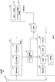
- FIG. 2 is a schematic block diagram showing the configuration of the base station apparatus 1A in the present embodiment.
- the base station apparatus 1A includes an upper layer processing unit (upper layer processing step) 101, a control unit (control step) 102, a transmission unit (transmission step) 103, a reception unit (reception step) 104, and an antenna. 105 is comprised.
- the upper layer processing unit 101 includes a radio resource control unit (radio resource control step) 1011 and a scheduling unit (scheduling step) 1012.
- the transmission unit 103 includes an encoding unit (encoding step) 1031, a modulation unit (modulation step) 1032, a frame configuration unit (frame configuration step) 1033, a multiplexing unit (multiplexing step) 1034, and a wireless transmission unit (radio transmission step). ) 1035.
- the reception unit 104 includes a wireless reception unit (wireless reception step) 1041, a demultiplexing unit (demultiplexing step) 1042, a demodulation unit (demodulation step) 1043, and a decoding unit (decoding step) 1044.
- the upper layer processing unit 101 includes a medium access control (Medium Access Control: MAC) layer, a packet data integration protocol (Packet Data Convergence Protocol: PDCP) layer, a radio link control (Radio Link Control: RLC) layer, a radio resource control (Radio) Resource (Control: RRC) layer processing.
- MAC Medium Access Control
- PDCP Packet Data Convergence Protocol
- RLC Radio Link Control
- RRC radio resource control
- upper layer processing section 101 generates information necessary for controlling transmission section 103 and reception section 104 and outputs the information to control section 102.
- the upper layer processing unit 101 receives information on the terminal device such as the function (UE capability, function information) of the terminal device from the terminal device. In other words, the terminal apparatus transmits its own function to the base station apparatus using an upper layer signal.
- information on a terminal device includes information indicating whether the terminal device supports a predetermined function, or information indicating that the terminal device has introduced a predetermined function and has completed a test.
- whether or not to support a predetermined function includes whether or not installation and testing for the predetermined function have been completed.
- the terminal device transmits information (parameters) indicating whether the predetermined function is supported.
- the terminal device does not transmit information (parameter) indicating whether or not the predetermined device is supported. That is, whether or not to support the predetermined function is notified by whether or not information (parameter) indicating whether or not to support the predetermined function is transmitted. Note that information (parameter) indicating whether or not to support a predetermined function may be notified using 1 bit of 1 or 0.
- the radio resource control unit 1011 generates or obtains downlink data (transport block), system information, RRC message, MAC CE, and the like arranged on the downlink PDSCH from an upper node.
- the radio resource control unit 1011 outputs downlink data to the transmission unit 103 and outputs other information to the control unit 102.
- the radio resource control unit 1011 manages various setting information of the terminal device.
- the scheduling unit 1012 determines the frequency and subframe to which the physical channels (PDSCH and PUSCH) are allocated, the coding rate and modulation scheme (or MCS) of the physical channels (PDSCH and PUSCH), transmission power, and the like.
- the scheduling unit 1012 outputs the determined information to the control unit 102.
- the scheduling unit 1012 generates information used for physical channel (PDSCH and PUSCH) scheduling based on the scheduling result.
- the scheduling unit 1012 outputs the generated information to the control unit 102.
- the control unit 102 generates a control signal for controlling the transmission unit 103 and the reception unit 104 based on the information input from the higher layer processing unit 101.
- the control unit 102 generates downlink control information based on the information input from the higher layer processing unit 101 and outputs the downlink control information to the transmission unit 103.
- the transmission unit 103 generates a downlink reference signal according to the control signal input from the control unit 102, and encodes the HARQ indicator, downlink control information, and downlink data input from the higher layer processing unit 101. And modulating, PHICH, PDCCH, EPDCCH, PDSCH, and downlink reference signal are multiplexed, and the signal is transmitted to the terminal apparatus 2 via the antenna 105.
- the encoding unit 1031 uses a predetermined encoding method such as block encoding, convolutional encoding, and turbo encoding for the HARQ indicator, downlink control information, and downlink data input from the higher layer processing unit 101. Encoding is performed using the encoding method determined by the radio resource control unit 1011.
- the modulation unit 1032 converts the encoded bits input from the encoding unit 1031 into BPSK (Binary Phase Shift Shift Keying), QPSK (quadrature Phase Shift Shift Keying), 16 QAM (quadrature Amplitude Modulation), 64 QAM, 256 QAM, and the like. Or it modulates with the modulation system which the radio
- the multiplexing unit 1034 multiplexes the modulated modulation symbol of each channel, the generated downlink reference signal, and downlink control information. That is, multiplexing section 1034 arranges the modulated modulation symbol of each channel, the generated downlink reference signal, and downlink control information in the resource element.
- the downlink reference signal is transmitted based on a known sequence obtained by the terminal device 2A based on a predetermined rule based on a physical cell identifier (PCI, cell ID) for identifying the base station device 1A. Generated by the unit 103.
- PCI physical cell identifier
- the frame configuration unit 1033 provides the frame configuration (frame format, frame structure, frame structure) of the transmission signal generated by the transmission unit 103.
- the operation of the frame configuration unit 1033 will be described later.
- the transmission unit 103 includes the frame configuration unit 1033.
- the transmission unit 103 may have a function of the frame configuration unit 1033 provided by another configuration unit.
- the upper layer processing unit 101 may have this function.
- the wireless transmission unit 1035 generates an OFDM symbol by performing inverse fast Fourier transform (Inverse Fast Transform: IFFT) on the multiplexed modulation symbol and the like, and adds a cyclic prefix (cyclic prefix: CP) to the OFDM symbol.
- IFFT inverse fast Fourier transform
- CP cyclic prefix
- the receiving unit 104 separates, demodulates, and decodes the received signal received from the terminal device 2A via the transmission / reception antenna 105 in accordance with the control signal input from the control unit 102, and outputs the decoded information to the upper layer processing unit 101. .
- the receiving unit 104 separates, demodulates, and decodes the received signal received from the terminal device 2A via the antenna 105 according to the control signal input from the control unit 102, and outputs the decoded information to the upper layer processing unit 101.
- the radio reception unit 1041 converts an uplink signal received via the transmission / reception antenna 105 into a baseband signal by down-conversion, removes unnecessary frequency components, and amplifies the signal level so that the signal level is properly maintained.
- the level is controlled, quadrature demodulation is performed based on the in-phase component and the quadrature component of the received signal, and the analog signal that has been demodulated is converted into a digital signal.
- the wireless reception unit 1041 removes a portion corresponding to the CP from the converted digital signal.
- Radio receiving section 1041 performs fast Fourier transform (FFT) on the signal from which CP has been removed, extracts a signal in the frequency domain, and outputs the signal to demultiplexing section 1042.
- FFT fast Fourier transform
- the demultiplexing unit 1042 demultiplexes the signal input from the wireless reception unit 1041 into signals such as PUCCH, PUSCH, and uplink reference signal. This separation is performed based on radio resource allocation information included in the uplink grant that is determined in advance by the radio resource control unit 1011 by the base station apparatus 1A and notified to each terminal apparatus 2.
- the demultiplexing unit 1042 compensates for the propagation paths of the PUCCH and PUSCH. Further, the demultiplexing unit 1042 demultiplexes the uplink reference signal.
- the demodulator 1043 performs inverse discrete Fourier transform (Inverse Discrete Fourier Transform: IDFT) on the PUSCH to obtain modulation symbols, and for each of the PUCCH and PUSCH modulation symbols, BPSK, QPSK, 16QAM, 64QAM, 256QAM, etc.
- IDFT inverse discrete Fourier transform
- the received signal is demodulated by using a modulation method determined or notified in advance by the own device to each of the terminal devices 2 using an uplink grant.
- the decoding unit 1044 uses the coding rate of the demodulated PUCCH and PUSCH in a predetermined encoding method, the predetermined coding method, or the coding rate notified by the own device to the terminal device 2 using the uplink grant. Decoding is performed, and the decoded uplink data and uplink control information are output to the upper layer processing section 101. When PUSCH is retransmitted, decoding section 1044 performs decoding using the coded bits held in the HARQ buffer input from higher layer processing section 101 and the demodulated coded bits.
- FIG. 3 is a schematic block diagram showing the configuration of the terminal device 2 (terminal device 2A and terminal device 2B) in the present embodiment.
- the terminal device 2A includes an upper layer processing unit (upper layer processing step) 201, a control unit (control step) 202, a transmission unit (transmission step) 203, a reception unit (reception step) 204, a channel state.
- An information generation unit (channel state information generation step) 205 and an antenna 206 are included.
- the upper layer processing unit 201 includes a radio resource control unit (radio resource control step) 2011 and a scheduling information interpretation unit (scheduling information interpretation step) 2012.
- the transmission unit 203 includes an encoding unit (encoding step) 2031, a modulation unit (modulation step) 2032, a frame configuration unit (frame configuration step) 2033, a multiplexing unit (multiplexing step) 2034, and a wireless transmission unit (radio transmission step). ) 2035.
- the reception unit 204 includes a wireless reception unit (wireless reception step) 2041, a demultiplexing unit (demultiplexing step) 2042, and a signal detection unit (signal detection step) 2043.
- the upper layer processing unit 201 outputs uplink data (transport block) generated by a user operation or the like to the transmission unit 203. Further, the upper layer processing unit 201 includes a medium access control (Medium Access Control: MAC) layer, a packet data integration protocol (Packet Data Convergence Protocol: PDCP) layer, a radio link control (Radio Link Control: RLC) layer, and a radio resource control. Process the (Radio Resource Control: RRC) layer.
- Medium Access Control Medium Access Control: MAC
- PDCP Packet Data Convergence Protocol
- RLC Radio Link Control
- RRC Radio Resource Control
- the upper layer processing unit 201 outputs information indicating the function of the terminal device supported by the own terminal device to the transmission unit 203.
- the radio resource control unit 2011 manages various setting information of the own terminal device. Also, the radio resource control unit 2011 generates information arranged in each uplink channel and outputs the information to the transmission unit 203.
- the radio resource control unit 2011 acquires setting information regarding CSI feedback transmitted from the base station apparatus, and outputs the setting information to the control unit 202.
- the scheduling information interpretation unit 2012 interprets the downlink control information received via the reception unit 204 and determines scheduling information.
- the scheduling information interpretation unit 2012 generates control information for controlling the reception unit 204 and the transmission unit 203 based on the scheduling information, and outputs the control information to the control unit 202.
- the control unit 202 generates a control signal for controlling the receiving unit 204, the channel state information generating unit 205, and the transmitting unit 203 based on the information input from the higher layer processing unit 201.
- the control unit 202 controls the reception unit 204 and the transmission unit 203 by outputting the generated control signal to the reception unit 204, the channel state information generation unit 205, and the transmission unit 203.
- the control unit 202 controls the transmission unit 203 to transmit the CSI generated by the channel state information generation unit 205 to the base station apparatus.
- the receiving unit 204 separates, demodulates and decodes the received signal received from the base station apparatus 1A via the antenna 206 according to the control signal input from the control unit 202, and outputs the decoded information to the higher layer processing unit 201. To do.
- the radio reception unit 2041 converts the downlink signal received via the antenna 206 into a baseband signal by down-conversion, removes unnecessary frequency components, and sets the amplification level so that the signal level is properly maintained. Based on the in-phase component and the quadrature component of the received signal, the signal is quadrature demodulated, and the quadrature demodulated analog signal is converted into a digital signal.
- the wireless reception unit 2041 removes a portion corresponding to CP from the converted digital signal, performs fast Fourier transform on the signal from which CP is removed, and extracts a frequency domain signal.
- the demultiplexing unit 2042 separates the extracted signal into PHICH, PDCCH, EPDCCH, PDSCH, and downlink reference signal. Further, the demultiplexing unit 2042 performs channel compensation of PHICH, PDCCH, and EPDCCH based on the channel estimation value of the desired signal obtained from the channel measurement, detects downlink control information, and Output. In addition, control unit 202 outputs PDSCH and the channel estimation value of the desired signal to signal detection unit 2043.
- the signal detection unit 2043 detects a signal using the PDSCH and the channel estimation value, and outputs the signal to the higher layer processing unit 201.
- the transmission unit 203 generates an uplink reference signal according to the control signal input from the control unit 202, encodes and modulates the uplink data (transport block) input from the higher layer processing unit 201, PUCCH, The PUSCH and the generated uplink reference signal are multiplexed and transmitted to the base station apparatus 1A via the antenna 206.
- the encoding unit 2031 performs encoding such as convolutional encoding and block encoding on the uplink control information input from the higher layer processing unit 201. Also, the coding unit 2031 performs turbo coding based on information used for PUSCH scheduling.
- the modulation unit 2032 modulates the coded bits input from the coding unit 2031 using a modulation scheme notified by downlink control information such as BPSK, QPSK, 16QAM, 64QAM, or a modulation scheme predetermined for each channel. .
- the multiplexing unit 2034 rearranges the PUSCH modulation symbols in parallel according to the control signal input from the control unit 202, and then performs a discrete Fourier transform (DFT). Also, the multiplexing unit 2034 multiplexes the PUCCH and PUSCH signals and the generated uplink reference signal for each transmission antenna port. That is, multiplexing section 2034 arranges the PUCCH and PUSCH signals and the generated uplink reference signal in the resource element for each transmission antenna port.
- the uplink reference signal is a physical cell identifier (physical cell identity: referred to as PCI, Cell ID, etc.) for identifying the base station device 1A, a bandwidth for arranging the uplink reference signal, and an uplink grant. Based on the notified cyclic shift, the value of the parameter for generating the DMRS sequence, and the like, the transmission unit 203 generates the value based on a sequence determined by a predetermined rule (formula).
- the frame configuration unit 2033 is a frame format (frame structure, frame type, frame format, frame pattern, frame generation method, frame definition) of the transmission signal generated by the transmission unit 203. ), Or information indicating the frame format, or the frame itself.
- the operation of the frame configuration unit 2033 will be described later.
- the function of the frame configuration unit 2033 may be included in another configuration unit (for example, the upper layer processing unit 201).
- the wireless transmission unit 2035 performs inverse fast Fourier transform (Inverse Fast Transform: IFFT) on the multiplexed signal, performs SC-FDMA modulation, generates SC-FDMA symbols, and generates the generated SC-FDMA symbols.
- IFFT inverse fast Fourier transform
- CP is added to baseband digital signal, baseband digital signal is converted to analog signal, excess frequency component is removed, converted to carrier frequency by up-conversion, power amplification, transmission / reception antenna It outputs to 206 and transmits.
- the signal detection unit 2043 can perform demodulation processing based on information on the multiplexing state of the transmission signal addressed to the own device and information on the retransmission state of the transmission signal addressed to the own device.
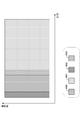
- FIG. 4 is a schematic diagram illustrating an example of a frame format (first frame format, first frame structure) of a downlink signal generated by the frame configuration unit 1033 according to the present embodiment.
- the first frame format includes a control signal resource 4000, a data signal resource 4001, a common reference signal (common RS, cell-specific RS) resource 4002, and a specific reference signal (specific RS, demodulation reference).
- the signal waveform (transmission method) for realizing the frame is not limited to anything, and a multicarrier transmission method represented by OFDM transmission or a single carrier transmission method represented by SC-FDMA transmission may be used.
- the first frame format is composed of a plurality of OFDM signals.
- the time length (time period) and bandwidth of each resource are not limited to anything.
- the control signal resource 4000 may have a 3OFDM symbol length as a time length and 12 subcarriers as a bandwidth.
- the first frame format can be aggregated in the time direction and the frequency direction.
- FIG. 5 is a schematic diagram illustrating an example of a frame format of a downlink signal generated by the frame configuration unit 1033 according to the present embodiment.
- one frame is configured by N subframes 5000 being aggregated in the time direction.
- the subframe 5000 can be configured in the first frame format shown in FIG.
- the frequency bandwidth occupied by the frame is the same as the frequency bandwidth of the subframe 5000, but the frame can aggregate the subframe 5000 in the frequency direction.
- the frequency bandwidth occupied by the frames is eight times the frequency bandwidth of the subframe 5000.
- the frame format shown in FIG. 4 is called a first subframe format
- the frame format shown in FIG. 5 is called a first frame format. I also mean.
- bundling a plurality of subframes to form one frame is called aggregation, but the frame configuration unit 1033 arranges a plurality of subframes in the time direction and the frequency direction. By doing so, it is possible to define the frame format generated as one frame format from the beginning. Further, the number bundled in the time direction and / or the frequency direction may be set as a parameter. In this case, this parameter is instructed from the base station apparatus to the terminal apparatus.
- control signal resource 4000 includes control information related to the downlink signal transmitted by the base station apparatus 1A.
- the control information is, for example, information that the base station device 1A transmits on the PDCCH.
- the control information includes common control information notified to all terminal devices connected to the base station device 1A and unique control information notified individually to each terminal device connected to the base station device 1A.
- the data signal resource 4001 includes a data signal transmitted by the base station device 1A.
- the data signal is, for example, information transmitted by the base station apparatus 1A using the PDSCH.
- a common reference signal (common RS, cell-specific reference signal) transmitted to all terminal apparatuses connected to the base station apparatus 1A is arranged.
- the common RS is used for the terminal device 2A to estimate information (for example, CSI) associated with the reception quality of the own device.
- the common RS is also used for the terminal device 2A to demodulate a signal transmitted by the control signal resource 4000.
- the common RS is also used for the terminal device 2A to detect the base station device 1A.
- the common RS is also used for the terminal device 2A to perform synchronization processing (sampling synchronization, FFT synchronization) on a signal transmitted from the base station device 1A.
- unique reference signals that are individually transmitted to the terminal apparatus 2 connected to the base station apparatus 1A are arranged.
- the unique RS is associated with a data signal addressed to each terminal device arranged in the data signal resource 4001 by the base station device 1A.
- the terminal device 2A can use the unique RS transmitted to the own device in order to demodulate the data signal addressed to the own device arranged in the data signal resource 4001.
- the data signal resource 4001 can include a common RS resource 4002 and a unique RS resource 4003 as shown in FIG.
- the frame configuration unit 1033 can dispose the common RS resource 4002 and the specific RS resource 4003 discretely in the time direction and the frequency direction.
- the frame configuration unit 1033 may further include a control information resource 4000 in addition to the data signal resource 4001.
- the control information resource 4000 provided in the data signal resource 4001 by the frame configuration unit 1033 is, for example, a resource in which the EPDCCH is arranged, and the resource is compared with a resource in which another signal is arranged in the data signal resource 4001. It may be time multiplexed or frequency multiplexed.
- the frame configuration unit 1033 can further include a synchronization signal resource 4004 and a broadcast signal resource 4007 with respect to the first frame format.
- a synchronization signal and a notification signal that are notified to the terminal device 2 that can receive a signal transmitted from the base station device 1A are arranged.
- the synchronization signal is a signal for the terminal device 2A to perform initial synchronization with respect to a signal transmitted from the base station device 1A.
- PSS Primary Synchronization Signal
- SSS Secondary Synchronization Signal, secondary synchronization
- the broadcast signal is a signal for the terminal device 2A to acquire system information related to the base station device 1A, and includes, for example, information that the base station device 1A transmits on the PBCH.
- Frame configuration section 1033 does not necessarily have to arrange synchronization signal resource 4004 and broadcast signal resource 4007 for all subframes.
- the base station apparatus 1A can notify (instruct) the terminal apparatus 2A of the resource position (or a resource candidate that may be arranged) where the synchronization signal resource 4004 and the broadcast signal resource 4007 are arranged. Further, the base station apparatus 1A and the terminal apparatus 2A can predetermine resource positions (or resource candidates that may be arranged) in which the synchronization signal resource 4004 and the broadcast signal resource 4007 are arranged.
- the information indicating the resource position includes a time resource (subframe number, OFDM signal number, frame number, slot number, etc.), frequency resource (subcarrier number, resource block number, frequency band number, etc.), spatial resource, etc. Information indicating (transmission antenna number, antenna port number, spatial stream number, etc.), code resource (spreading code sequence, code generation formula, code generation seed, etc.) and the like is included.
- the base station apparatus 1A when it is described that “the base station apparatus 1A notifies the terminal apparatus 2A of information”, the information is transmitted between the base station apparatus 1A and the terminal apparatus 2A unless otherwise specified. It also includes a state that is shared in advance (or a state that is determined in advance). In general, when the base station apparatus 1A notifies the terminal apparatus 2A of information, the overhead increases, but it is possible to cope with a radio propagation environment that changes every moment. On the other hand, if the base station apparatus 1A and the terminal apparatus 2A share information in advance, it may be difficult to cope with a radio propagation environment that changes from time to time, but the overhead decreases.
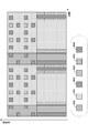
- FIG. 6 is a schematic diagram illustrating an example of a frame format (second frame format, second frame structure) of a downlink signal generated by the frame configuration unit 1033 according to the present embodiment.
- the second frame format includes at least one of a control signal resource 4000, a data signal resource 4001, a common RS resource 4002, and a specific RS resource 4003.
- the common RS resource 4002 and the data signal resource 4001 are sequentially arranged in time.
- a common RS resource 4002 and a control signal resource 4000 are arranged in the first half of the frame.
- the unique RS resource 4003 is also arranged in the first half of the frame, but the frame configuration unit 1033 can include the unique RS resource 4003 in the data signal resource 4001.
- the frame configuration unit 1033 can arrange the specific RS resource 4003 in the range of the data signal resource 4001 discretely in the time direction and the frequency direction.
- the frame configuration unit 1033 may further include a control information resource 4000 in addition to the data signal resource 4001.
- the signal arranged in the control information resource 4000 included in the data signal resource 4001 by the frame configuration unit 1033 is, for example, a signal transmitted on the EPDCCH.
- Control information resource 4000 may be time-multiplexed or frequency-multiplexed with respect to resources in which other signals are arranged in data signal resource 4001.
- the terminal device 2A that receives the transmission signal generated based on the second frame format uses the common RS arranged in the common RS resource 4002 arranged in the first half of the frame, so that the device that has transmitted the transmission signal Initial synchronization processing can be performed.
- the frame configuration unit 1033 according to the present embodiment can include the synchronization signal resource 4004 in the common RS resource 4002 in the second frame format.
- the frame configuration unit 1033 can make the resource for arranging the common RS resource 4002 and the resource for arranging the synchronization signal resource 4004 common.
- the frame configuration unit 1033 can set a part of the common RS arranged in the common RS resource 4002 as a synchronization signal.
- the frame configuration unit 1033 can share a resource for arranging the synchronization signal resource 4004 for the first frame format and a resource for arranging the synchronization signal for the second frame format, or different resources. It can also be.
- the base station apparatus 1A uses the same signal as the synchronization signal transmitted by the synchronization signal resource 4004 arranged in the first frame format and the synchronization signal transmitted by the synchronization signal resource 4004 arranged in the second frame format. Can be different signals.
- the same signal includes that at least a part of information included in the signal or a radio parameter applied to the signal is common.
- the reception unit 204 of the terminal device 2A Synchronization processing can be performed on a plurality of resources where the resource 4004 may be arranged. And the receiving part 204 of 2 A of terminal devices can recognize the frame format of the signal which the own apparatus has received based on the result of the synchronous process with respect to this some resource.
- the terminal device 2A when the receiving unit 204 of the terminal device 2A performs a synchronization process on a resource in which the synchronization signal resource 4004 may be arranged in the second frame format, and determines that synchronization is achieved as a result, the terminal The receiving unit 204 of the device 2A can recognize that the frame format of the signal received by the device 2A is the second frame format. That is, the terminal device 2A can detect the frame format blindly. According to the above method, the terminal device 2A can detect the frame format blindly by the synchronization process.
- the frame configuration unit 1033 can further include a broadcast signal resource 4007 in the second frame format. Similar to the first frame format, the frame configuration unit 1033 does not need to include the broadcast signal resource 4007 in all transmission signals.
- the resource that the frame configuration unit 1033 arranges the broadcast signal resource 4007 for the second frame format may be the same as the resource that the frame configuration unit 1033 arranges the broadcast signal resource 4007 for the first frame format. It can be a different resource.
- the base station apparatus 1A and the terminal apparatus 2A can predetermine resources (or resource candidates that may be allocated) in which the synchronization signal resource 4004 and the broadcast signal resource 4007 are allocated for each frame format.
- the base station device 1A can notify the terminal device 2A of the resource or the resource candidate group by notifying the terminal device 2A of the frame format of the signal transmitted by itself.
- the base station apparatus 1A transmits the information included in the signal transmitted by the broadcast signal resource 4007 arranged for the first frame format and the broadcast signal resource 4007 arranged for the second frame format.
- the information included in the signal to be transmitted can be common or different information.
- the base station apparatus 1A transmits the radio parameters (coding rate, modulation scheme, code length, spreading factor, etc.) of the signal transmitted by the broadcast signal resource 4007 arranged for the first frame format,
- the radio parameter of the signal transmitted by the broadcast signal resource 4007 arranged for the frame format can be made common or different radio parameters can be used.
- the base station device 1A can notify the terminal device 2A of resources (or resource candidates that may be arranged) in which the frame configuration unit 1033 arranges the broadcast signal resource 4007 for the second frame format. .
- the base station apparatus 1A individually assigns a resource for disposing the broadcast signal resource 4007 for the first frame format and a resource for disposing the broadcast signal resource 4007 for the second frame format to the terminal apparatus 2A individually. You can be notified.
- information on each resource that the base station apparatus 1A notifies the terminal apparatus 2A can be determined in advance between the base station apparatus 1A and the terminal apparatus 2A.
- the terminal device 2A connected to the base station device 1A can recognize the frame format of the signal received by itself by acquiring information included in the signal transmitted by the broadcast signal resource 4007.
- the reception unit 204 of the terminal device 2A has the broadcast signal resource 4007 arranged.
- the broadcast signal can be demodulated for a resource that has a possibility of being transmitted.
- the terminal device 2A can recognize the frame format of the signal received by the own device based on the information indicating the resource where the broadcast signal that has been correctly demodulated is arranged. That is, the terminal device 2A can detect the frame format blindly. According to the above method, the terminal device 2A can detect the frame format blindly by acquiring the notification signal.
- the frame configuration unit 1033 uses the frame format shown in FIG. 6 as the second subframe format (second subframe) and aggregates the subframes in the time direction and the frequency direction. Can define the second frame format.
- the frame configuration unit 1033 can aggregate a frame including all of the common RS resource 4001, the control information resource 4000, the data signal resource 4001, and the specific RS resource 4003 when the subframes are aggregated.
- a frame including a specific combination of resources can be aggregated.
- the frame configuration unit 1033 can aggregate a plurality of data signal resources 4001 when the frames are aggregated.
- FIG. 7 is a schematic diagram illustrating an example of a frame format (second frame format) of a downlink signal generated by the frame configuration unit 1033 according to the present embodiment.
- FIG. 7A shows a case where aggregation is not performed.
- the frame configuration unit 1033 can aggregate the data signal resource 4001 in the time direction.
- the base station apparatus 1A can flexibly change the frame format according to the data size (payload size) addressed to the terminal apparatus 2A.
- the frame configuration unit 1033 can also aggregate the specific RS resource 4003 in the time direction in addition to the data signal resource 4001.
- 1 A of base station apparatuses can arrange
- the base station device 1A can provide stable wireless communication to the terminal device 2 in a high-speed moving environment.
- the frame configuration unit 1033 can aggregate the data signal resource 4001 in the time direction, but the frame length of the data signal resource 4001 to be aggregated is the frame length when the aggregation is not performed (see FIG. 7D).
- the frame lengths of the frames to be aggregated can be made uniform.
- the frame configuration unit 1033 can also aggregate the common RS resource 4002 and the control signal resource 4000 in the time direction. Further, as shown in FIG. 7G and FIG. 7H, the frame configuration unit 1033 can include a non-transmission section (null section, null section) of the base station apparatus 1A in the frame format.
- the length of the non-transmission section may be the same as the length of the data signal resource 4001 or may be an integer multiple of the elements (for example, OFDM signal length) constituting the data signal resource 4001.
- the frame configuration unit 1033 can also aggregate the control information resource 4000, the common RS resource 4002, and the unique RS resource 4003 as shown in FIG. 7 (i).
- the frame configuration unit 1033 aggregates the common RS resource 4002, so that the transmission unit 103 can apply different beam forming to the common RS transmitted by each common RS resource. Therefore, for example, the terminal device 2A can notify the connected base station device 1A of the reception quality associated with the plurality of common RSs.
- the frame configuration unit 1033 can use the second frame format that does not include the control information resource 4000, and the second frame format that does not include the control information resource 4000 and the common RS resource 4002.
- a frame format can also be used.
- the base station apparatus 1A when the base station apparatus 1A transmits a signal based on the second frame format that does not include the control information resource 4000 and the common RS resource 4002, the base station apparatus 1A ,
- the second frame format including the control information resource 4000 and the common RS resource 4002 can be transmitted.
- the base station apparatus 1A transmits a signal based on the second frame format that does not include the control information resource 4000 and the common RS resource 4002 to a signal transmitted in a high frequency band of 6 GHz or higher, but less than 6 GHz.
- the signal to be transmitted in the low frequency band can be transmitted based on the second frame format including the control information resource 4000 and the common RS resource 4002.
- 1 A of base station apparatuses can transmit a signal based on the 2nd frame format which does not contain the specific RS resource 4003 and the data signal resource 4001 in the signal transmitted in a low frequency band below 6 GHz.
- each resource included in each aggregated signal (for example, the common RS resource 4001 or the like)
- the number of resources of the data signal resource 4002) may be common or may be different from each other.
- the number of resources is associated with the signal length and frequency bandwidth of the signals to be aggregated.
- the frame lengths and frequency bandwidths of a plurality of frames to be aggregated may be common or may have different values.
- the relationship between the frame length and the frequency bandwidth between the frames is preferably an integer multiple relationship.
- FIG. 8 is a schematic diagram showing one configuration example of the frame format according to the present embodiment.
- the frame configuration unit 1033 can include an RF switching period 4005 and an uplink signal resource 4006 for the second frame format.
- the frame format shown in FIG. 8 can be used by the base station apparatus 1A and the terminal apparatus 2A that use time division duplex (Time T division duplex: TDD) as a duplex system.
- the RF switching period 4005 is a period used by the terminal apparatus that has received the signal transmitted by the base station apparatus 1A based on the frame format to switch the reception operation of the own apparatus to the transmission operation.
- the base station apparatus 1A may set the RF switching period 4005 as a non-transmission period, or may transmit some signal (for example, a common RS).
- the frame configuration unit 1033 may provide an RF switching period 4005 also in the second half of the uplink signal resource 4006. It is also possible to set a non-transmission section between frames transmitted continuously. Note that the base station apparatus 1A uses the second frame format, uses TDD, sets the RF switching period 4005 and the uplink signal resource 4006 to the second frame format, and uses FDD. Can generate a transmission signal based on each second frame format without setting the RF switching period 4005 and the uplink signal resource 4006 to the second frame format.
- the terminal device 2A that has received the transmission signal transmitted by the base station device 1A based on the frame format shown in FIG. 8 is information (ACK or NACK) that indicates whether or not the data signal addressed to itself is placed in the data signal resource 4001. ) Can be arranged in the uplink signal resource 4006 and transmitted to the base station apparatus 1A. Therefore, since the base station apparatus 1A can immediately know whether or not the data signal addressed to the terminal apparatus 2A has been correctly received, the delay time related to the transmission of the downlink signal can be shortened. It becomes.
- the frame configuration unit 1033 can define a plurality of frame formats including the first frame format and the second frame format.
- the frame configuration unit 1033 can define a plurality of frame formats by changing the radio parameters of the first frame format and the second frame format.
- the radio parameters include frequency bandwidth, center frequency, frequency band, subcarrier interval, number of subcarriers, symbol length, FFT / IFFT sampling period, GI length, CP length, frame length, subframe length, slot length. , TTI, number of FFT points, type of error correction code to be applied (for example, turbo code is applied to the first frame format, low density parity check code is applied to the second frame format, etc.), etc.
- radio parameters when different radio parameters are set with the same frame format, they are also called different types (modes). For example, when radio parameter 1 and radio parameter 2 having different values with respect to the first frame format are set, they can be referred to as first frame format type 1 and first frame format type 2, respectively.
- the base station apparatus can have a wireless parameter set in which each value included in the wireless parameter is set in advance.
- One or a plurality of radio parameter sets can be set, and the frame configuration unit 1033 can set different frame formats / frame format types by changing the radio parameter set.
- each wireless parameter set can be set with a simple rule.
- the subcarrier interval of radio parameter set 2 is X (X is an integer of 2 or more) times the subcarrier interval of radio parameter set 1, and the subcarrier interval of radio parameter set 3 is The subcarrier interval of the radio parameter set 2 can be Y (Y is an integer of 2 or more) times.
- the radio parameter set is transmitted (instructed) from the base station apparatus to the terminal apparatus.
- the terminal apparatus can know the frame format / frame type from the radio parameter set received from the base station apparatus.
- the frame format type is also included even when the frame format is referred to, unless otherwise specified. Further, whether or not the wireless parameter set is supported can be determined as the capability of the terminal.
- the base station apparatus 1A can use a plurality of frame formats selectively or simultaneously. Further, the base station apparatus 1A can selectively set different radio parameters or a part of them in common for the first frame format and the second frame format. The base station apparatus 1A can notify the terminal apparatus 2A of information indicating the frame format used by the own apparatus for the transmission signal.
- the information indicating the frame format includes information (numerical value, index, indicator) indicating one of a plurality of frame formats predefined by the base station apparatus 1A, and information indicating the resources included in the frame format (for example, Control information resource 4000, data signal resource 4001, common RS resource 4002, information indicating which specific RS resource 4003 is included or not included), resources in which each resource is allocated, and possible allocation It includes information indicating potential resource candidates.
- the base station apparatus 1A can notify at least a part of the information indicating the frame format to the terminal apparatus 2A by PHY layer signaling, or can be notified by higher layer signaling such as RRC signaling. it can.
- the base station apparatus 1A can switch and use the frame format according to the use case (or use scenario) in which the own apparatus provides communication services. Further, the base station apparatus 1A can change and use the radio parameter of the frame format according to the use scenario in which the own apparatus provides a communication service.
- the base station apparatus 1A In order to satisfy a plurality of use scenarios, the base station apparatus 1A according to the present embodiment combines a plurality of frame formats (set, set) or a combination of a plurality of radio parameter sets set in the frame format (set, Set).
- the base station apparatus 1A selects a frame format from a frame format set (or a combination of radio parameter sets) prepared in advance according to a use case in which the own apparatus provides a communication service, and transmits a transmission signal transmitted by the own apparatus. Can be generated.
- the frame format set provided in the base station apparatus 1A may be the same as or different from the frame format set provided in other base station apparatuses.
- the base station device 1A can notify the terminal device 2A connected to the base device of the frame format set provided in the base device.
- the base station device 1A can switch and select a plurality of transmission modes in order to satisfy a plurality of use scenarios.
- the transmission mode is defined by a combination of a radio parameter, a multiplexing method, a scheduling method, a precoding method, and the like that can be used when the transmission unit 103 of the base station apparatus 1A generates a transmission signal.
- a frame format can be assigned to each of the plurality of transmission modes. Note that the frame formats / radio parameters assigned to a plurality of transmission modes may all be different, or some of them may be common. In this case, the base station apparatus 1A can selectively use a plurality of frame formats / radio parameters by selecting a transmission mode.
- the base station apparatus 1A has a plurality of frame formats for each of EMBB (Enhanced mobile broadband), EMTC (Enhanced massive machine type communication), and URLLC (Ultra-reliable and low latency communication) using three use scenarios. Can be used selectively or simultaneously. Further, the base station apparatus 1A can use the second frame format with different radio parameters for each of EMBB, EMTC, and URLLC.
- the frame configuration unit 1033 can select a frame format and determine a radio parameter set in the frame format according to a use scenario in which the base station apparatus 1A provides a communication service.
- the base station apparatus 1A generates a frame based on the first frame format for the downlink signal related to EMBB, and generates a frame based on the second frame format for the downlink signal related to MMTC and URLLC. can do.
- the base station apparatus 1A switches the frame format according to the use case (or use scenario) in which the own apparatus provides the communication service.
- the method according to the present embodiment does not necessarily require a frame for each use case.
- the format is not limited to being defined.
- the base station apparatus 1A can selectively or simultaneously use a plurality of frame formats / radio parameters based on a radio medium in which the base station apparatus transmits a downlink signal.
- the wireless medium can include wireless resources such as time resources and frequency resources.
- the radio medium can include radio resources that are distinguished by a duplex method applied to a frequency band in which the base station apparatus 1A transmits a downlink signal.
- the radio medium can include radio resources that are distinguished according to use cases (or use scenarios) in which the base station apparatus 1A provides communication services.
- the base station apparatus 1A can select a wireless medium to be used according to a use case (or use scenario) for providing a communication service.
- 1 A of base station apparatuses can determine beforehand the radio
- the base station apparatus 1A transmits information indicating a plurality of frame formats / radio parameters used selectively or simultaneously to the terminal apparatus 2A based on a radio medium in which the base station apparatus transmits a downlink signal. This can be notified by higher layer signaling such as / MAC layer or RRC signaling. Note that the base station apparatus 1A does not have to notify the terminal apparatus 2A of all the information indicating the plurality of frame formats / radio parameters. For example, the base station apparatus 1A can select the plurality of frame formats / radio parameter candidates. Can be notified to the terminal device 2A.
- the terminal apparatus 2A is signaled by the base station apparatus 1A by the above-described method, information indicating a plurality of frame formats / radio parameters used selectively or simultaneously by the base station apparatus 1A based on the radio medium. It is also possible to blindly detect some information. Note that the terminal apparatus 2A can notify the base station apparatus 1A of information regarding the plurality of frame formats / radio parameters that can be received by the terminal apparatus 2A.
- the base station apparatus 1A can selectively or simultaneously use a plurality of frame formats / radio parameters according to the frequency (frequency band, channel) for transmitting the downlink signal.
- the base station apparatus 1A can divide frequencies that can transmit downlink signals into a plurality of groups.
- the base station apparatus 1A uses a frequency lower than 6 GHz (Below 6 GHz) as a frequency band 1, a frequency higher than 6 GHz (Above 6 GHz) as a frequency band 2, and transmits a downlink signal in the frequency band 1,
- the frame format can be switched and used when a downlink signal is transmitted in band 2.
- the base station apparatus 1A transmits a downlink signal in each frequency band, with a frequency less than 2 GHz as a frequency band 1, a frequency between 2 GHz and less than 6 GHz as a frequency band 2, and a frequency greater than 6 GHz as a frequency band 3.
- the transmission signal can be generated based on the frame format defined in each frequency band.
- FIG. 9 is a schematic diagram illustrating a configuration example of a downlink signal transmitted by the base station apparatus 1A according to the present embodiment.
- the base station apparatus 1A uses different frame formats depending on the frequency.
- the base station apparatus 1A can mix a plurality of different frame formats in one OFDM signal. For example, a plurality of subcarriers constituting one OFDM signal are divided into a plurality of subcarrier groups, and transmission signals arranged in each subcarrier group are generated based on different frame formats.
- the second frame format includes an RF switching period 4005 and an uplink signal resource 4006. Therefore, the base station apparatus 1A generates a signal based on the first frame format and a signal based on the second frame format with different OFDM signals, and frequency-multiplexes and transmits the different OFDM signals simultaneously. be able to.
- the subcarrier group generated based on the first frame format and the subcarrier group generated based on the second frame format are adjacent to each other, but the frame The configuration unit 1033 can also arrange a guard band (null subcarrier, no transmission frequency) between the subcarrier groups.
- the signal transmitted in each of the subcarrier group generated based on the first frame format and the subcarrier group generated based on the second frame format is the same, the frame length of each signal may be different. However, from the viewpoint of synchronization within the wireless network, it is preferable that the relationship between the frame lengths of signals transmitted in each subcarrier group is an integer multiple relationship.
- the transmission unit 103 of the base station device 1A can generate a filtered OFDM signal that applies a filter for each subcarrier or for each subcarrier group configured by a plurality of subcarriers.
- the filtered OFDM can be, for example, a filter bank multicarrier or a filtered OFDM. In filtered OFDM, interference between subcarriers (or between subcarrier groups) is significantly suppressed.
- Base station apparatus 1A can assign different frame formats to a plurality of subcarrier groups generated by itself.
- the transmission unit 103 of the base station device 1A generates a first subcarrier group based on the first frame format, generates a second subcarrier group based on the second frame format, Filtered OFDM signal including the second subcarrier group and the second subcarrier group can be generated.
- the base station apparatus 1A can define a frame format for each duplex method.
- the base station apparatus 1A can define different frame formats for FDD and TDD.
- FDD Frequency Division Duplex
- TDD Time Division Duplex
- the base station apparatus 1A generates a transmission signal based on the first frame format
- TDD Time Division Duplex
- the base station apparatus 1A can generate a transmission signal based on the second frame format.
- the base station apparatus 1A can selectively use a plurality of frame formats in one duplex system. For example, the base station apparatus 1A can selectively or simultaneously use the first frame format and the second frame format when FDD is used as a duplex system. Further, the base station apparatus 1A can selectively or simultaneously use a plurality of radio parameters for the first frame format (or the second frame format) in one duplex system.
- the base station apparatus 1A can use a duplex scheme in which FDD and TDD are mixed, and the base station apparatus 1A defines a frame format for the duplex scheme in which FDD and TDD are mixed. Can do. Further, the base station apparatus 1A can selectively or simultaneously use a plurality of frame formats or radio parameters in a duplex scheme in which FDD and TDD are mixed. As a duplex scheme in which FDD and TDD are mixed, the base station apparatus 1A can use a duplex scheme that temporally switches between FDD and TDD in a frequency band. As a duplex scheme in which FDD and TDD are mixed, the base station apparatus 1A can use a full duplex (or simultaneous transmission and reception (STR)) that simultaneously performs uplink transmission and downlink transmission. In STR, base station apparatus 1A and terminal apparatus 2A can simultaneously transmit transmission signals generated based on different frame formats.
- STR simultaneous transmission and reception
- the frequency band for transmitting the transmission signal generated based on each frame format is the country in which the wireless provider provides the service.
- a frequency band called a licensed band (licensed band) for which use permission (license) has been obtained from the country or region, and a so-called unlicensed band (does not require use permission from the country or region) Different radio parameters can be set depending on the frequency band called.
- the base station device 1A When the frequency band for transmitting a transmission signal generated based on each frame format is an unlicensed band for the radio parameters set to the first frame format and the second frame format, the base station device 1A
- the radio parameter to be set can be changed according to the frequency band of the license band.
- the base station device 1A can change the radio parameter depending on whether the unlicensed band for transmitting the transmission signal is a 5 GHz band or the 60 GHz band.
- the base station apparatus 1A can use the frame format obtained by extending the occupied frequency bandwidth of the frame format used in the 5 GHz band unlicensed band by an integral multiple for the 60 GHz band unlicensed band. Further, the base station apparatus 1A can bundle a plurality of transmission signals generated in a frame format used for a license band of 6 GHz or more in the frequency direction and use it for an unlicensed band of 60 GHz band.
- the base station apparatus 1A in cooperation with only its own apparatus and other base station apparatuses, generates component carriers generated based on a frame format used for a license band of 6 GHz or more, and CA (Carrier Aggregation) and A plurality of DCs (Dual Connectivity) can be simultaneously transmitted to the terminal device 2A in an unlicensed band of 60 GHz band.
- CA Carrier Aggregation
- DCs Dual Connectivity
- the base station apparatus 1A In the unlicensed band of 60 GHz band, the base station apparatus 1A has the same bandwidth as the channel bandwidth defined by IEEE802.11ad (for example, 2 GHz or 2.16 GHz), or an integral multiple of the bandwidth.
- a frame format can be used.
- the base station apparatus 1A uses a 60 GHz band unlicensed band or 6 GHz in a frame format in which an integral multiple of a frequency bandwidth (including an equal multiple) matches the channel bandwidth defined in IEEE 802.11ad. It can be used for the above license bands.
- a radio carrier occupies a frequency band for transmitting a transmission signal generated based on each frame format for radio parameters set in the first frame format and the second frame format. Different radio parameters can be set for the occupied frequency band that can be used and for the shared frequency band that is shared and used by a plurality of wireless operators.
- the base station apparatus 1A can arrange a plurality of transmission signals generated based on different frame formats in the frequency direction.
- the base station apparatus 1A aggregates a plurality of component carriers (CC) and transmits the plurality of transmission signals by carrier aggregation (CA). Signals can be sent simultaneously.
- CC component carriers
- CA carrier aggregation
- a plurality of CCs transmitted by the carrier aggregation can be transmitted from a plurality of different base station apparatuses.
- carrier aggregation one primary cell (PCell: Primary Cell) and one or more secondary cells (SCell: Secondary Cell) are set as a set of serving cells.
- PCell Primary Cell
- SCell Secondary Cell
- the base station apparatus 1A can use different frame formats / radio parameters for a plurality of CCs transmitted by CA. For example, when the base station apparatus 1A performs 2CC CA transmission, the first frame format can be applied to the first CC, and the second frame format can be applied to the second CC. . Further, the base station apparatus 1A can generate a transmission signal to be transmitted in each CC based on the second frame format in which different radio parameters are set. That is, the base station apparatus 1A can set the frame format / radio parameter for each cell. For example, 1 A of base station apparatuses can communicate by a 1st frame format in PCell / SCell, and can communicate by a 2nd frame format in SCell. The base station apparatus 1A communicates with the PCell and the SCell in the second frame format, but the set radio parameter can be different for each cell.
- the base station apparatus 1A can include information indicating the frame format set in the CC serving as the secondary cell in the control information arranged in the control information resource 4000 included in the CC serving as the primary cell.
- the base station apparatus 1A cooperates with other base station apparatuses to simultaneously transmit signals from a plurality of transmission points.
- DC a master cell group (MCG: Master Cell Group) and a secondary cell group (SCG: Secondary Cell Group) are set as groups of serving cells.
- MCG Master Cell Group
- SCG Secondary Cell Group
- the MCG is composed of a PCell and optionally one or more SCells.
- the SCG includes a primary SCell (PSCell) and optionally one or a plurality of SCells.
- the base station apparatus 1A and the base station apparatus 1B transmit a downlink signal to the terminal apparatus 2A by DC
- the base station apparatus 1A and the base station apparatus 1B transmit based on different frame formats / radio parameters, respectively.
- a signal can be generated and transmitted.
- the base station device 1A and the base station device 1B transmit a downlink signal to the terminal device 2A by DC
- the base station device 1A and the base station device 1B have the second frame in which different radio parameters are set.
- a transmission signal can be generated and transmitted based on the format. In other words, the base station apparatus 1A can set the frame format / radio parameter for each cell.
- different frame formats are set for PCell and PSCell, and different frame formats are set for PCell / PSCell and SCell.
- the base station apparatus 1A / 1B can set the second frame format in which different radio parameters are set for the PCell and the PSCell.
- the base station apparatus 1A can notify the terminal apparatus 2A of information regarding the frame format / radio parameters set for each downlink signal arranged in the frequency direction. In the case of CA or DC, the base station apparatus 1A can transmit information on the frame format / radio parameters set for each cell to the terminal apparatus 2A.
- the base station apparatus 1A can arrange a plurality of transmission signals generated based on different frame formats / radio parameters in the spatial direction. For example, when the base station apparatus 1A simultaneously transmits a downlink signal to the terminal apparatus 2A and the terminal apparatus 2B by multi-user multiple input multiple output transmission (MU-MIMO), a transmission signal addressed to the terminal apparatus 2A The transmission signal addressed to the terminal device 2B can be generated based on different frame formats, and the two transmission signals can be spatially multiplexed and transmitted. That is, the transmission signal transmitted by the base station apparatus 1A according to the present embodiment can be spatially multiplexed with transmission signals generated based on different frame formats in the spatial direction.
- MU-MIMO multi-user multiple input multiple output transmission
- the base station device 1A When the base station device 1A multiplexes transmission signals generated based on different frame formats in the spatial direction, the base station device 1A shares at least a part of the resources in which the unique RS resource 4003 is arranged for each frame format. It can be.
- the base station device 1A transmits assist information for removing or suppressing inter-user interference or adjacent cell interference. Can do. Assisting information (neighboring cell information), physical cell ID, CRS number of ports, P A list, P B, MBSFN (Multimedia Broadcast multicast service Single Frequency Network) subframe configuration, transmission mode list, the resource allocation granularity, TDD of UL / It includes DL subframe configuration, ZP / NZP CSI-RS configuration, QCL (quasi co-location) information, frame format, and some or all of radio parameters.
- Assisting information neighborhboring cell information
- Physical cell ID Physical cell ID
- CRS number of ports P A list
- P B MBSFN (Multimedia Broadcast multicast service Single Frequency Network) subframe configuration
- transmission mode list the resource allocation granularity
- TDD of UL / It includes DL subframe configuration, ZP / NZP CSI-RS configuration, QCL (quasi co-location) information, frame format,
- P A is the PDSCH and CRS power ratio in OFDM symbols CRS is not arranged (power offset).
- P B represents the power ratio (power offset) between the PDSCH in the OFDM symbol in which the CRS is arranged and the PDSCH in the OFDM symbol in which the CRS is not arranged.
- the QCL information is information related to the QCL for a predetermined antenna port, a predetermined signal, or a predetermined channel. In two antenna ports, if the long-term characteristics of the channel carrying the symbol on one antenna port can be inferred from the channel carrying the symbol on the other antenna port, those antenna ports are QCL It is called. Long interval characteristics include delay spread, Doppler spread, Doppler shift, average gain and / or average delay.
- each parameter included in the assist information may be set to one value (candidate) or a plurality of values (candidates).
- the terminal device interprets that the parameter indicates a value that may be set by the base station device that causes interference, and sets the interference signal from the multiple values. Detect (specify) the parameters that are being used.
- the assist information may indicate information of another base station apparatus / beam, or may indicate information of its own base station apparatus / beam. The assist information may be used when performing various measurements.
- the measurement includes RRM (Radio Resource Management) measurement, RLM (Radio Link Monitoring) measurement, and CSI (Channel State Information) measurement.
- the base station apparatus and terminal apparatus can be used for a radio access technology (RAT) that is not limited to a license band but is operated in an unlicensed band.
- RAT radio access technology
- the RAT operated in the unlicensed band can be license-assisted access that can receive the assistance of the license band.
- the base station apparatus and terminal apparatus can be used in dual connectivity (DC) in which signals are transmitted (or received) from a plurality of transmission points (or a plurality of reception points). is there.
- the base station device and the terminal device can be used for communication with at least one of a plurality of transmission points (or reception points) connected by DC.
- the base station apparatus and terminal apparatus according to an aspect of the present invention can be used in carrier aggregation (CA) in which a plurality of component carriers (CC) are used.
- CA carrier aggregation
- CC component carriers
- the base station apparatus and the terminal apparatus can be used only for the primary cell among a plurality of CCs to be CA, can be used only for the secondary cell, and both the primary cell and the secondary cell Can also be used.
- the program that operates on the base station apparatus and the terminal apparatus is a program that controls the CPU and the like (a program that causes a computer to function) so as to realize the functions of the above-described embodiments related to the present invention. is there.
- Information handled by these devices is temporarily stored in the RAM at the time of processing, then stored in various ROMs and HDDs, read out by the CPU, and corrected and written as necessary.
- a recording medium for storing the program a semiconductor medium (for example, ROM, nonvolatile memory card, etc.), an optical recording medium (for example, DVD, MO, MD, CD, BD, etc.), a magnetic recording medium (for example, magnetic tape, Any of a flexible disk etc. may be sufficient.
- the processing is performed in cooperation with the operating system or other application programs.
- the functions of the invention may be realized.
- the program when distributing to the market, can be stored in a portable recording medium for distribution, or transferred to a server computer connected via a network such as the Internet.
- the storage device of the server computer is also included in the present invention.
- LSI which is typically an integrated circuit.
- Each functional block of the receiving apparatus may be individually chipped, or a part or all of them may be integrated into a chip. When each functional block is integrated, an integrated circuit controller for controlling them is added.
- the method of circuit integration is not limited to LSI, and may be realized by a dedicated circuit or a general-purpose processor.
- an integrated circuit based on the technology can also be used.
- the terminal device of the present invention is not limited to application to a mobile station device, but is a stationary or non-movable electronic device installed indoors or outdoors, such as AV equipment, kitchen equipment, cleaning / washing equipment Needless to say, it can be applied to air-conditioning equipment, office equipment, vending machines, and other daily life equipment.
- the present invention is suitable for use in a base station device, a terminal device, and a communication method.
Abstract
Provided are a base station, a terminal, and a communication method with which a wireless access network that is able to flexibly cope with various requirements is achieved. A base station according to an embodiment of the present invention communicates with a terminal, and is provided with a transmitting unit that generates a transmission signal on the basis of a frame format that enables a wireless parameter to be set, said wireless parameter, which is set by the frame format, being set on the basis of the wireless medium through which the transmitting unit transmits the transmission signal.
Description
本発明は、基地局装置、端末装置および通信方法に関する。
The present invention relates to a base station device, a terminal device, and a communication method.
3GPP(Third Generation Partnership Project)によるLTE(Long Term Evolution)、LTE-A(LTE-Advanced)のような通信システムでは、基地局装置(基地局、送信局、送信点、下りリンク送信装置、上りリンク受信装置、送信アンテナ群、送信アンテナポート群、コンポーネントキャリア、eNodeB、アクセスポイント、AP)あるいは基地局装置に準じる送信局がカバーするエリアをセル(Cell)状に複数配置するセルラ構成とすることにより、通信エリアを拡大することができる。基地局装置には、端末装置(受信局、受信点、下りリンク受信装置、上りリンク送信装置、受信アンテナ群、受信アンテナポート群、UE、ステーション、STA)が接続する。このセルラ構成において、隣接するセルまたはセクタ間で同一周波数を利用することで、周波数利用効率を向上させることができる。
In a communication system such as LTE (Long Termination Evolution) or LTE-A (LTE-Advanced) by 3GPP (Third Generation Partnership Project), a base station device (base station, transmitting station, transmission point, downlink transmitting device, uplink) By adopting a cellular configuration in which a plurality of areas covered by a receiving station, a transmitting antenna group, a transmitting antenna port group, a component carrier, an eNodeB, an access point, an AP) or a transmitting station according to a base station apparatus are arranged in a cell shape The communication area can be expanded. Terminal devices (receiving station, receiving point, downlink receiving device, uplink transmitting device, receiving antenna group, receiving antenna port group, UE, station, STA) are connected to the base station device. In this cellular configuration, frequency utilization efficiency can be improved by using the same frequency between adjacent cells or sectors.
LTE/LTE-Aでは、周波数分割複信、時間分割複信、およびライセンス補助アクセスに対し、それぞれフレームフォーマットが定義されている。例えば、周波数分割複信を用いるLTE/LTE-Aの基地局装置および端末装置は、通信帯域幅等に依らず、常に共通のフレームフォーマットを用いて通信を行なうことができる。
In LTE / LTE-A, frame formats are defined for frequency division duplex, time division duplex, and license auxiliary access. For example, LTE / LTE-A base station apparatuses and terminal apparatuses using frequency division duplex can always perform communication using a common frame format regardless of the communication bandwidth.
また、2020年頃の商業サービス開始を目指し、第5世代移動無線通信システム(5Gシステム)に関する研究・開発活動が盛んに行なわれている。最近、国際標準化機関である国際電気通信連合 無線通信部門(International Telecommunication Union Radio communications Sector: ITU-R)より、5Gシステムの標準方式(International mobile telecommunication - 2020 and beyond: IMT-2020)に関するビジョン勧告が報告された(非特許文献1参照)。
Also, with the aim of starting commercial services around 2020, research and development activities related to 5th generation mobile radio communication systems (5G systems) are being actively conducted. Recently, an international standardization organization, International Telecommunication Union, Radio Communications Sector (International Telecommunication Union Radio Sector: SITU: ITU-R) has made a vision recommendation on the standard system of 5G systems (International mobile telecommunication-2020 and and beyond: IMT-2020). Has been reported (see Non-Patent Document 1).
ビジョン勧告では、5Gシステムが通信サービスを提供する様々なユースケースを3つの大きなユースシナリオ(Enhanced mobile broadband(EMBB)、Enhanced Massive machine type communication(eMTC)、Ultra-reliable and low latency communication(URLLC))に分類している。また、ビジョン勧告は、5Gシステムの要求条件(Capabilities)として、8つの指標(Peak data rate, User experienced data rate, Spectrum efficiency, Mobility, Latency, Connection density, Network energy efficiency, Area traffic capacity)を提示している。しかし、ビジョン勧告は、5Gシステムは、該要求条件を全て同時に満たす必要ななく、ユースシナリオ毎に要求条件を満たせば良いことも指摘している。当然、ユースケース/ユースシナリオ毎に要求条件は異なるため、5Gシステムが備える無線アクセスネットワークが提供する無線性能は、時々刻々とダイナミックに変化していくことが求められる。
According to the Vision Recommendation, various large use scenarios (EnhancedEnhancemobile broadband (EMBB), Enhanced Massive machine type communication (eMTC), Ultra-reliable and low latency communication (URLLC)) It is classified into. In addition, the vision recommendation presents eight indicators (Peak data rate, User experienced data rate, Spectrum efficiency, Mobility, Latency, Connection density, Network energy efficiency, Area traffic capacity) as 5G system requirements (Capabilities). ing. However, the vision recommendation also points out that the 5G system does not have to satisfy all of the requirements at the same time, but only has to satisfy the requirements for each use scenario. Naturally, since the requirements differ for each use case / use scenario, the wireless performance provided by the wireless access network provided in the 5G system is required to change dynamically every moment.
しかしながら、一般に無線通信システムにおいては、システムの複雑性を鑑み、無線インターフェースは共通のフレームフォーマットを用いている場合が多い。従来のLTE/LTE-Aにおいても、複信方式毎に1つの共通のフレームフォーマットが定義されている。しかし、共通のフレームフォーマットでは、無線アクセスネットワークが、時々刻々と変化する要求条件に対応することには限界が生ずる。しかし、フレームフォーマットの種類をいたずらに増加させることは、システムの複雑性およびオーバーヘッドを増加させ、無線アクセスネットワークの能力を低下させてしまう。
However, in general, in a wireless communication system, in consideration of the complexity of the system, the wireless interface often uses a common frame format. Also in the conventional LTE / LTE-A, one common frame format is defined for each duplex method. However, with a common frame format, the radio access network is limited in meeting the ever-changing requirements. However, unnecessarily increasing the type of frame format increases the complexity and overhead of the system and reduces the capabilities of the radio access network.
本発明はこのような事情を鑑みてなされたものであり、その目的は、様々な要求条件に柔軟に対応可能な無線アクセスネットワークを実現する、基地局装置、端末装置および通信方法を提供することにある。
The present invention has been made in view of such circumstances, and an object thereof is to provide a base station device, a terminal device, and a communication method that realize a radio access network that can flexibly cope with various requirements. It is in.
上述した課題を解決するために本発明の一態様に係る基地局装置、端末装置および通信方法の構成は、次の通りである。
In order to solve the above-described problem, configurations of a base station apparatus, a terminal apparatus, and a communication method according to an aspect of the present invention are as follows.
(1)本発明の一態様に係る基地局装置は、端末装置と通信を行なう基地局装置であって、無線パラメータが設定可能なフレームフォーマットに基づいて送信信号を生成する送信部を備え、前記フレームフォーマットに設定される無線パラメータは、前記送信部が前記送信信号を送信する無線媒体に基づいて設定される。
(1) A base station apparatus according to an aspect of the present invention is a base station apparatus that communicates with a terminal apparatus, and includes a transmission unit that generates a transmission signal based on a frame format in which radio parameters can be set, The radio parameter set in the frame format is set based on a radio medium in which the transmission unit transmits the transmission signal.
(2)また、本発明の一態様に係る基地局装置は、上記(1)に記載の基地局装置であって、前記フレームフォーマットは、共通参照信号リソースと、データ信号リソースを含み、前記共通参照信号リソースと、前記データ信号リソースは、時間方向にシーケンシャルに配置される。
(2) Moreover, the base station apparatus which concerns on 1 aspect of this invention is a base station apparatus as described in said (1), Comprising: The said frame format contains a common reference signal resource and a data signal resource, The said common The reference signal resource and the data signal resource are sequentially arranged in the time direction.
(3)また、本発明の一態様に係る基地局装置は、上記(1)に記載の基地局装置であって、前記送信部は、前記送信信号を送信する周波数に基づいて、前記無線パラメータの値を設定する。
(3) Moreover, the base station apparatus which concerns on 1 aspect of this invention is a base station apparatus as described in said (1), Comprising: The said transmission part is the said radio | wireless parameter based on the frequency which transmits the said transmission signal. Set the value of.
(4)また、本発明の一態様に係る基地局装置は、上記(1)に記載の基地局装置であって、前記送信部は、複数の複信方式を選択可能であり、前記複数の複信方式のそれぞれに対して、前記無線パラメータの値を設定する。
(4) Moreover, the base station apparatus which concerns on 1 aspect of this invention is a base station apparatus as described in said (1), Comprising: The said transmission part can select a some duplex system, The value of the radio parameter is set for each duplex method.
(5)また、本発明の一態様に係る基地局装置は、上記(1)に記載の基地局装置であって、前記送信部は、プライマリセル、セカンダリセル、プライマリセカンダリセルのそれぞれに対して前記無線パラメータの値を設定する。
(5) Moreover, the base station apparatus which concerns on 1 aspect of this invention is a base station apparatus as described in said (1), Comprising: The said transmission part is with respect to each of a primary cell, a secondary cell, and a primary secondary cell. The value of the wireless parameter is set.
(6)また、本発明の一態様に係る基地局装置は、上記(1)に記載の基地局装置であって、前記無線パラメータはサブキャリア間隔を含む。
(6) Moreover, the base station apparatus which concerns on 1 aspect of this invention is a base station apparatus as described in said (1), Comprising: The said radio | wireless parameter contains a subcarrier space | interval.
(7)また、本発明の一態様に係る基地局装置は、上記(2)に記載の基地局装置であって、前記送信部は、前記フレームフォーマットとはリソース配置の異なる第1のフレームフォーマットと、前記フレームフォーマットである第2のフレームフォーマットを、選択的に、もしくは同時に用いて前記送信信号を生成する。
(7) Moreover, the base station apparatus which concerns on 1 aspect of this invention is a base station apparatus as described in said (2), Comprising: The said transmission part is 1st frame format from which the resource arrangement differs from the said frame format The transmission signal is generated using the second frame format, which is the frame format, selectively or simultaneously.
(8)また、本発明の一態様に係る端末装置は、基地局装置と通信を行なう端末装置であって、前記基地局装置が通信に用いる無線媒体に基づいて、フレームフォーマットに設定される無線パラメータのうち、自装置が復調可能な無線パラメータを含む機能情報を、前記基地局装置に通知する送信部と、を備える。
(8) A terminal apparatus according to an aspect of the present invention is a terminal apparatus that communicates with a base station apparatus, and is a wireless set in a frame format based on a wireless medium that the base station apparatus uses for communication. A transmission unit for notifying the base station apparatus of functional information including radio parameters that can be demodulated by the own apparatus.
(9)また、本発明の一態様に係る端末装置は、上記(8)に記載の端末装置であって、前記無線パラメータを示す情報を取得し、前記無線パラメータが設定されたフレームフォーマットに基づいて前記基地局装置が生成した信号を復調する受信部と、を備える。
(9) Moreover, the terminal device according to one aspect of the present invention is the terminal device according to (8), wherein the terminal device acquires information indicating the wireless parameter, and is based on a frame format in which the wireless parameter is set. And a receiving unit that demodulates the signal generated by the base station apparatus.
(10)また、本発明の一態様に係る端末装置は、上記(9)に記載の端末装置であって、前記受信部が復調する信号は、前記フレームフォーマットとはリソース配置が異なる第1のフレームフォーマットと、前記フレームフォーマットである第2のフレームフォーマットが、選択的に、もしくは同時に用いられて生成されている。
(10) Further, the terminal device according to one aspect of the present invention is the terminal device according to (9), wherein the signal demodulated by the reception unit has a resource arrangement different from that of the frame format. The frame format and the second frame format which is the frame format are generated selectively or simultaneously.
(11)また、本発明の一態様に係る通信方法は、端末装置と通信を行なう基地局装置の通信方法であって、無線パラメータが設定可能なフレームフォーマットに基づいて送信信号を生成するステップと、を備え、前記フレームフォーマットに設定される無線パラメータは、前記送信信号を送信される無線媒体に基づいて設定される。
(11) A communication method according to an aspect of the present invention is a communication method of a base station device that communicates with a terminal device, and generates a transmission signal based on a frame format in which radio parameters can be set; , And the radio parameter set in the frame format is set based on a radio medium through which the transmission signal is transmitted.
(12)また、本発明の一態様に係る通信方法は、基地局装置と通信を行なう端末装置の通信方法であって、前記基地局装置が通信に用いる無線媒体に基づいて、フレームフォーマットに設定される無線パラメータのうち、自装置が復調可能な無線パラメータを含む機能情報を、前記基地局装置に通知するステップと、を備える。
(12) A communication method according to an aspect of the present invention is a communication method of a terminal device that communicates with a base station device, and the frame format is set based on a wireless medium used for communication by the base station device. And notifying the base station apparatus of function information including radio parameters that can be demodulated by the own apparatus.
本発明の一態様によれば、様々な要求条件に柔軟に対応可能な無線アクセスネットワークが提供されるから、要求条件が異なる様々なユースケースおよびユースシナリオに対し、無線通信サービスを効率的に提供することが可能となる。
According to one aspect of the present invention, a wireless access network that can flexibly respond to various requirements is provided, and thus wireless communication services are efficiently provided for various use cases and use scenarios with different requirements. It becomes possible to do.
本実施形態における通信システムは、基地局装置(送信装置、セル、送信点、送信アンテナ群、送信アンテナポート群、コンポーネントキャリア、eNodeB、アクセスポイント、AP、無線ルータ、中継、通信装置)および端末装置(端末、移動端末、受信点、受信端末、受信装置、受信アンテナ群、受信アンテナポート群、UE、ステーション、STA)を備える。
The communication system in this embodiment includes a base station device (transmitting device, cell, transmission point, transmitting antenna group, transmitting antenna port group, component carrier, eNodeB, access point, AP, wireless router, relay, communication device) and terminal device. (Terminal, mobile terminal, receiving point, receiving terminal, receiving device, receiving antenna group, receiving antenna port group, UE, station, STA).
本実施形態において、“X/Y”は、“XまたはY”の意味を含む。本実施形態において、“X/Y”は、“XおよびY”の意味を含む。本実施形態において、“X/Y”は、“Xおよび/またはY”の意味を含む。
In this embodiment, “X / Y” includes the meaning of “X or Y”. In the present embodiment, “X / Y” includes the meanings of “X and Y”. In the present embodiment, “X / Y” includes the meaning of “X and / or Y”.
[1.第1の実施形態]
図1は、本実施形態に係る通信システムの例を示す図である。図1に示すように、本実施形態における通信システムは、基地局装置1A、端末装置2A、2Bを備える。また、カバレッジ1-1は、基地局装置1Aが端末装置と接続可能な範囲(通信エリア)である。なお、本実施形態に係る通信システムは、複数の基地局装置や、3以上の端末装置を含むことが可能である。 [1. First Embodiment]
FIG. 1 is a diagram illustrating an example of a communication system according to the present embodiment. As shown in FIG. 1, the communication system according to the present embodiment includes a base station device 1A and terminal devices 2A and 2B. The coverage 1-1 is a range (communication area) in which the base station device 1A can be connected to the terminal device. Note that the communication system according to the present embodiment can include a plurality of base station apparatuses and three or more terminal apparatuses.
図1は、本実施形態に係る通信システムの例を示す図である。図1に示すように、本実施形態における通信システムは、基地局装置1A、端末装置2A、2Bを備える。また、カバレッジ1-1は、基地局装置1Aが端末装置と接続可能な範囲(通信エリア)である。なお、本実施形態に係る通信システムは、複数の基地局装置や、3以上の端末装置を含むことが可能である。 [1. First Embodiment]
FIG. 1 is a diagram illustrating an example of a communication system according to the present embodiment. As shown in FIG. 1, the communication system according to the present embodiment includes a base station device 1A and
図1において、端末装置2から基地局装置1Aへの上りリンクの無線通信では、以下の上りリンク物理チャネルが用いられる。上りリンク物理チャネルは、上位層から出力された情報を送信するために使用される。
・PUCCH(Physical Uplink Control Channel)
・PUSCH(Physical Uplink Shared Channel)
・PRACH(Physical Random Access Channel) In FIG. 1, the following uplink physical channels are used in uplink wireless communication from the terminal apparatus 2 to the base station apparatus 1A. The uplink physical channel is used for transmitting information output from an upper layer.
-PUCCH (Physical Uplink Control Channel)
・ PUSCH (Physical Uplink Shared Channel)
・ PRACH (Physical Random Access Channel)
PUCCHは、上りリンク制御情報(Uplink Control Information: UCI)を送信するために用いられる。ここで、上りリンク制御情報は、下りリンクデータ(下りリンクトランスポートブロック、Downlink-Shared Channel: DL-SCH)に対するACK(a positive acknowledgement)またはNACK(a negative acknowledgement)(ACK/NACK)を含む。下りリンクデータに対するACK/NACKを、HARQ-ACK、HARQフィードバックとも称する。
The PUCCH is used for transmitting uplink control information (Uplink Control Information: UCI). Here, the uplink control information includes ACK (a positive acknowledgement) or NACK (a negative acknowledgement) (ACK / NACK) for downlink data (downlink transport block, Downlink-Shared Channel: DL-SCH). ACK / NACK for downlink data is also referred to as HARQ-ACK and HARQ feedback.
また、上りリンク制御情報は、下りリンクに対するチャネル状態情報(Channel State Information: CSI)を含む。また、上りリンク制御情報は、上りリンク共用チャネル(Uplink-Shared Channel: UL-SCH)のリソースを要求するために用いられるスケジューリング要求(Scheduling Request: SR)を含む。前記チャネル状態情報は、好適な空間多重数を指定するランク指標RI、好適なプレコーダを指定するプレコーディング行列指標PMI、好適な伝送レートを指定するチャネル品質指標CQI等が該当する。
Also, the uplink control information includes channel state information (Channel State Information: CSI) for the downlink. Further, the uplink control information includes a scheduling request (Scheduling Request: SR) used to request resources of an uplink shared channel (Uplink-Shared Channel: UL-SCH). The channel state information corresponds to a rank index RI that specifies a suitable spatial multiplexing number, a precoding matrix index PMI that specifies a suitable precoder, a channel quality index CQI that specifies a suitable transmission rate, and the like.
前記チャネル品質指標CQIは(以下、CQI値)、所定の帯域(詳細は後述)における好適な変調方式(例えば、QPSK、16QAM、64QAM、256QAM等)、符号化率(code rate)とすることができる。CQI値は、前記変更方式や符号化率により定められたインデックス(CQI Index)とすることができる。前記CQI値は、予め当該システムで定めたものをすることができる。
The channel quality indicator CQI (hereinafter referred to as CQI value) is a suitable modulation scheme (for example, QPSK, 16QAM, 64QAM, 256QAM, etc.) and a code rate in a predetermined band (details will be described later). it can. The CQI value can be an index (CQI Index) determined by the change method and coding rate. The CQI value can be predetermined by the system.
なお、前記ランク指標、前記プレコーディング品質指標は、予めシステムで定めたものとすることができる。前記ランク指標や前記プレコーディング行列指標は、空間多重数やプレコーディング行列情報により定められたインデックスとすることができる。なお、前記ランク指標、前記プレコーディング行列指標、前記チャネル品質指標CQIの値をCSI値と総称する。
Note that the rank index and the precoding quality index can be determined in advance by the system. The rank index and the precoding matrix index can be indexes determined by the spatial multiplexing number and precoding matrix information. Note that the values of the rank index, the precoding matrix index, and the channel quality index CQI are collectively referred to as CSI values.
PUSCHは、上りリンクデータ(上りリンクトランスポートブロック、UL-SCH)を送信するために用いられる。また、PUSCHは、上りリンクデータと共に、ACK/NACKおよび/またはチャネル状態情報を送信するために用いられても良い。また、PUSCHは、上りリンク制御情報のみを送信するために用いられても良い。
The PUSCH is used for transmitting uplink data (uplink transport block, UL-SCH). Moreover, PUSCH may be used to transmit ACK / NACK and / or channel state information together with uplink data. Moreover, PUSCH may be used in order to transmit only uplink control information.
また、PUSCHは、RRCメッセージを送信するために用いられる。RRCメッセージは、無線リソース制御(Radio Resource Control: RRC)層において処理される情報/信号である。また、PUSCHは、MAC CE(Control Element)を送信するために用いられる。ここで、MAC CEは、媒体アクセス制御(MAC: Medium Access Control)層において処理(送信)される情報/信号である。
Also, PUSCH is used to transmit an RRC message. The RRC message is information / signal processed in a radio resource control (Radio-Resource-Control: -RRC) layer. The PUSCH is used to transmit a MAC CE (Control Element). Here, the MAC CE is information / signal processed (transmitted) in the medium access control (MAC) layer.
例えば、パワーヘッドルームは、MAC CEに含まれ、PUSCHを経由して報告されても良い。すなわち、MAC CEのフィールドが、パワーヘッドルームのレベルを示すために用いられても良い。
For example, the power headroom may be included in the MAC CE and reported via PUSCH. That is, the MAC CE field may be used to indicate the power headroom level.
PRACHは、ランダムアクセスプリアンブルを送信するために用いられる。
PRACH is used to transmit a random access preamble.
また、上りリンクの無線通信では、上りリンク物理信号として上りリンク参照信号(Uplink Reference Signal: UL RS)が用いられる。上りリンク物理信号は、上位層から出力された情報を送信するためには使用されないが、物理層によって使用される。ここで、上りリンク参照信号には、DMRS(Demodulation Reference Signal)、SRS(Sounding Reference Signal)が含まれる。
In uplink wireless communication, an uplink reference signal (Uplink Reference Signal: UL SRS) is used as an uplink physical signal. The uplink physical signal is not used for transmitting information output from the upper layer, but is used by the physical layer. Here, the uplink reference signal includes DMRS (Demodulation Reference Signal) and SRS (Sounding Reference Signal).
DMRSは、PUSCHまたはPUCCHの送信に関連する。例えば、基地局装置1Aは、PUSCHまたはPUCCHの伝搬路補正を行なうためにDMRSを使用する。SRSは、PUSCHまたはPUCCHの送信に関連しない。例えば、基地局装置1Aは、上りリンクのチャネル状態を測定するためにSRSを使用する。基地局装置1Aは、SRSの設定情報を、上位レイヤのシグナリングもしくは後述するDCIフォーマットで通知することができる。基地局装置1Aは、DMRSの設定情報を、上位レイヤのシグナリングもしくは後述するDCIフォーマットで通知することができる。
DMRS is related to transmission of PUSCH or PUCCH. For example, base station apparatus 1A uses DMRS to perform propagation channel correction for PUSCH or PUCCH. SRS is not related to PUSCH or PUCCH transmission. For example, the base station apparatus 1A uses SRS to measure the uplink channel state. The base station apparatus 1A can notify SRS setting information by higher layer signaling or a DCI format described later. The base station apparatus 1A can notify DMRS setting information by higher layer signaling or a DCI format described later.
SRSは、複数のトリガのされ方が定義される。例えば、上位レイヤのシグナリングによりトリガされるトリガータイプ0と、後述する下りリンク制御情報によりトリガされるトリガータイプ1である。
SRS defines how to trigger multiple times. For example, trigger type 0 triggered by higher layer signaling and trigger type 1 triggered by downlink control information described below.
SRSは、セル固有のSRS(Cell specific SRS, Common SRS)とUE固有のSRS(UE-specific SRS, Dedicated SRS)を含む。UE-specific SRSは周期的に送信されるSRS(UE-specific periodic SRS)と、トリガに基づいて非周期的に送信されるSRS(UE-specific aperiodic SRS)を含む。
SRS includes cell-specific SRS (Cell specific SRS, Common SRS) and UE specific SRS (UE-specific SRS, Dedicated SRS). The UE-specific SRS includes an SRS (UE-specific periodic さ れ る SRS) transmitted periodically and an SRS (UE-specific aperiodic SRS) transmitted aperiodically based on a trigger.
Common SRSは、上位レイヤのシグナリング、もしくは後述する下りリンク制御情報により、送信帯域幅(srs-BandwidthConfig)と、送信されるサブフレーム(srs-SubframeConfig)が指定される。また、Commmon SRSは所定のパラメータ(例えば、ackNackSRS-SimultaneousTransmission)がFalseであった場合、HARQ-ACKとSRの少なくとも1つを含むPUCCHが含まれるサブフレームでは送信されない。一方で、Commmon SRSは所定のパラメータ(例えば、ackNackSRS-SimultaneousTransmission)がTrueであった場合、HARQ-ACKとSRの少なくとも1つを含むPUCCHが含まれるサブフレームで送信されることができる。
In Common SRS, a transmission bandwidth (srs-BandwidthConfig) and a subframe to be transmitted (srs-SubframeConfig) are designated by upper layer signaling or downlink control information described later. Also, when a predetermined parameter (for example, ackNackSRS-SimultaneousTransmission) is False, the Common SRS is not transmitted in a subframe including a PUCCH including at least one of HARQ-ACK and SR. On the other hand, the common SRS can be transmitted in a subframe including a PUCCH including at least one of HARQ-ACK and SR when a predetermined parameter (for example, ackNackSRS-SimultaneousTransmission) is True.
Dedicated SRSは、上位レイヤのシグナリング、もしくは後述する下りリンク制御情報により、送信帯域幅と、ホッピング帯域幅(srs-HoppingBandwidth)と、周波数割当開始位置(freqDomainPosition)と、送信期間(Duration)(Single transmissionもしくはindefinite transmission)と、送信周期(srs-ConfigIndex)と、SRSの信号系列に与えられる巡回シフト量(cyclicShift)と、櫛の歯に形成されるSRSの位置(transmissionComb)が、それぞれ設定される。
Dedicated SRS is based on upper layer signaling or downlink control information described later, transmission bandwidth, hopping bandwidth (srs-HoppingBandwidth), frequency allocation start position (freqDomainPosition), transmission period (Duration) (Singleationtransmission) Alternatively, the indefinite transmission, the transmission cycle (srs-ConfigIndex), the cyclic shift amount (cyclicShift) given to the SRS signal sequence, and the SRS position (transmissionComb) formed on the comb teeth are set.
SRSは、複数のアンテナポートより送信されることができる。送信アンテナポート数は上位レイヤのシグナリングにより設定される。複数のアンテナポートにおけるSRS送信が設定されたUEは、サービングセルに対して、同じサブフレームの1つのSC-FDMAシンボルにより、設定された送信アンテナポートの全てからSRSを送信しなければならない。この場合、設定された送信アンテナポートから送信されるSRSは、全て同じ送信帯域幅と、周波数割当開始位置が設定される。
SRS can be transmitted from multiple antenna ports. The number of transmit antenna ports is set by higher layer signaling. A UE in which SRS transmission in multiple antenna ports is configured must transmit SRS from all configured transmit antenna ports to one serving cell using one SC-FDMA symbol in the same subframe. In this case, the same transmission bandwidth and frequency allocation start position are set for all SRSs transmitted from the set transmission antenna ports.
複数のTransmission advance groups(TAGs)が設定されないUEは、SRSとPUSCHが同じシンボル内でオーバーラップしない限り、SRSを送信してはならない。
UEs for which multiple Transmission advance groups (TAGs) are not set must not transmit SRS unless SRS and PUSCH overlap in the same symbol.
TDDのサービングセルに対して、サービングセルのUpPTSに1つのSC-FDMAシンボルが含まれている場合、UEは該SC-FDMAシンボルをSRSの送信に用いることができる。サービングセルのUpPTSに2つのSC-FDMAシンボルが含まれている場合、UEは該2つのSC-FDMAシンボルの両方をSRSの送信に用いることができる。また、トリガータイプ0のSRSは、同じUEに対して、該2つのSC-FDMAシンボルの両方をSRSに設定されることができる。
When one SC-FDMA symbol is included in the UpPTS of the serving cell for the TDD serving cell, the UE can use the SC-FDMA symbol for transmission of the SRS. If the serving cell's UpPTS includes two SC-FDMA symbols, the UE can use both of the two SC-FDMA symbols for SRS transmission. In addition, the trigger type 0 SRS can set both of the two SC-FDMA symbols to the SRS for the same UE.
図1において、基地局装置1Aから端末装置2Aへの下りリンクの無線通信では、以下の下りリンク物理チャネルが用いられる。下りリンク物理チャネルは、上位層から出力された情報を送信するために使用される。
・PBCH(Physical Broadcast Channel: 報知チャネル)
・PCFICH(Physical Control Format Indicator Channel: 制御フォーマット指示チャネル)
・PHICH(Physical Hybrid automatic repeat request Indicator Channel: HARQ指示チャネル)
・PDCCH(Physical Downlink Control Channel: 下りリンク制御チャネル)
・EPDCCH(Enhanced Physical Downlink Control Channel: 拡張下りリンク制御チャネル)
・PDSCH(Physical Downlink Shared Channel: 下りリンク共有チャネル) In FIG. 1, the following downlink physical channels are used in downlink radio communication from the base station apparatus 1A to theterminal apparatus 2A. The downlink physical channel is used for transmitting information output from an upper layer.
・ PBCH (Physical Broadcast Channel)
・ PCFICH (Physical Control Format Indicator Channel)
・ PHICH (Physical Hybrid automatic repeat request Indicator Channel: HARQ instruction channel)
・ PDCCH (Physical Downlink Control Channel)
・ EPDCCH (Enhanced Physical Downlink Control Channel)
・ PDSCH (Physical Downlink Shared Channel)
・PBCH(Physical Broadcast Channel: 報知チャネル)
・PCFICH(Physical Control Format Indicator Channel: 制御フォーマット指示チャネル)
・PHICH(Physical Hybrid automatic repeat request Indicator Channel: HARQ指示チャネル)
・PDCCH(Physical Downlink Control Channel: 下りリンク制御チャネル)
・EPDCCH(Enhanced Physical Downlink Control Channel: 拡張下りリンク制御チャネル)
・PDSCH(Physical Downlink Shared Channel: 下りリンク共有チャネル) In FIG. 1, the following downlink physical channels are used in downlink radio communication from the base station apparatus 1A to the
・ PBCH (Physical Broadcast Channel)
・ PCFICH (Physical Control Format Indicator Channel)
・ PHICH (Physical Hybrid automatic repeat request Indicator Channel: HARQ instruction channel)
・ PDCCH (Physical Downlink Control Channel)
・ EPDCCH (Enhanced Physical Downlink Control Channel)
・ PDSCH (Physical Downlink Shared Channel)
PBCHは、端末装置で共通に用いられるマスターインフォメーションブロック(Master Information Block: MIB, Broadcast Channel: BCH)を報知するために用いられる。PCFICHは、PDCCHの送信に用いられる領域(例えば、OFDMシンボルの数)を指示する情報を送信するために用いられる。
The PBCH is used to broadcast a master information block (Master Information Block: MIB, Broadcast Channel: BCH) that is commonly used by terminal devices. PCFICH is used for transmitting information indicating a region (for example, the number of OFDM symbols) used for transmission of PDCCH.
PHICHは、基地局装置1Aが受信した上りリンクデータ(トランスポートブロック、コードワード)に対するACK/NACKを送信するために用いられる。すなわち、PHICHは、上りリンクデータに対するACK/NACKを示すHARQインディケータ(HARQフィードバック)を送信するために用いられる。また、ACK/NACKは、HARQ-ACKとも呼称する。端末装置2Aは、受信したACK/NACKを上位レイヤに通知する。ACK/NACKは、正しく受信されたことを示すACK、正しく受信しなかったことを示すNACK、対応するデータがなかったことを示すDTXである。また、上りリンクデータに対するPHICHが存在しない場合、端末装置2AはACKを上位レイヤに通知する。
PHICH is used to transmit ACK / NACK for uplink data (transport block, codeword) received by the base station apparatus 1A. That is, PHICH is used to transmit a HARQ indicator (HARQ feedback) indicating ACK / NACK for uplink data. ACK / NACK is also referred to as HARQ-ACK. The terminal device 2A notifies the received ACK / NACK to the upper layer. ACK / NACK is ACK indicating that the data has been correctly received, NACK indicating that the data has not been correctly received, and DTX indicating that there is no corresponding data. Further, when there is no PHICH for the uplink data, the terminal device 2A notifies the upper layer of ACK.
PDCCHおよびEPDCCHは、下りリンク制御情報(Downlink Control Information: DCI)を送信するために用いられる。ここで、下りリンク制御情報の送信に対して、複数のDCIフォーマットが定義される。すなわち、下りリンク制御情報に対するフィールドがDCIフォーマットに定義され、情報ビットへマップされる。
PDCCH and EPDCCH are used to transmit downlink control information (Downlink Control Information: DCI). Here, a plurality of DCI formats are defined for transmission of downlink control information. That is, fields for downlink control information are defined in the DCI format and mapped to information bits.
例えば、下りリンクに対するDCIフォーマットとして、1つのセルにおける1つのPDSCH(1つの下りリンクトランスポートブロックの送信)のスケジューリングに使用されるDCIフォーマット1Aが定義される。
For example, a DCI format 1A used for scheduling one PDSCH (transmission of one downlink transport block) in one cell is defined as a DCI format for the downlink.
例えば、下りリンクに対するDCIフォーマットには、PDSCHのリソース割り当てに関する情報、PDSCHに対するMCS(Modulation and Coding Scheme)に関する情報、PUCCHに対するTPCコマンド等の下りリンク制御情報が含まれる。ここで、下りリンクに対するDCIフォーマットを、下りリンクグラント(または、下りリンクアサインメント)とも称する。
For example, the DCI format for the downlink includes information on PDSCH resource allocation, information on MCS (Modulation & Coding Scheme) for PDSCH, and downlink control information such as a TPC command for PUCCH. Here, the DCI format for the downlink is also referred to as a downlink grant (or downlink assignment).
また、例えば、上りリンクに対するDCIフォーマットとして、1つのセルにおける1つのPUSCH(1つの上りリンクトランスポートブロックの送信)のスケジューリングに使用されるDCIフォーマット0が定義される。
Also, for example, as a DCI format for uplink, DCI format 0 used for scheduling one PUSCH (transmission of one uplink transport block) in one cell is defined.
例えば、上りリンクに対するDCIフォーマットには、PUSCHのリソース割り当てに関する情報、PUSCHに対するMCSに関する情報、PUSCHに対するTPCコマンド等上りリンク制御情報が含まれる。上りリンクに対するDCIフォーマットを、上りリンクグラント(または、上りリンクアサインメント)とも称する。
For example, the DCI format for uplink includes information on PUSCH resource allocation, information on MCS for PUSCH, and uplink control information such as TPC command for PUSCH. The DCI format for the uplink is also referred to as uplink grant (or uplink assignment).
また、上りリンクに対するDCIフォーマットは、下りリンクのチャネル状態情報(CSI: Channel State Information。受信品質情報とも称する。)を要求(CSI request)するために用いることができる。チャネル状態情報は、好適な空間多重数を指定するランク指標RI(Rank Indicator)、好適なプリコーダを指定するプリコーディング行列指標PMI(Precoding Matrix Indicator)、好適な伝送レートを指定するチャネル品質指標CQI(Channel Quality Indicator)、プリコーディングタイプ指標PTI(Precoding type Indicator)等が該当する。
Also, the DCI format for uplink can be used to request downlink channel state information (CSI: “Channel State Information”, also referred to as reception quality information). The channel state information includes a rank index RI (Rank Indicator) designating a suitable spatial multiplexing number, a precoding matrix indicator PMI (Precoding Matrix Indicator) designating a suitable precoder, and a channel quality index CQI (Designated a suitable transmission rate). Channel Quality Indicator), precoding type indicator PTI (Precoding type Indicator), and the like.
また、上りリンクに対するDCIフォーマットは、端末装置が基地局装置にフィードバックするチャネル状態情報報告(CSI feedback report)をマップする上りリンクリソースを示す設定のために用いることができる。例えば、チャネル状態情報報告は、定期的にチャネル状態情報(Periodic CSI)を報告する上りリンクリソースを示す設定のために用いることができる。チャネル状態情報報告は、定期的にチャネル状態情報を報告するモード設定(CSI report mode)のために用いることができる。
Also, the DCI format for the uplink can be used for setting indicating an uplink resource for mapping a channel state information report (CSI feedback report) that the terminal apparatus feeds back to the base station apparatus. For example, the channel state information report can be used for setting indicating an uplink resource that periodically reports channel state information (Periodic CSI). The channel state information report can be used for mode setting (CSI report mode) for periodically reporting the channel state information.
例えば、チャネル状態情報報告は、不定期なチャネル状態情報(Aperiodic CSI)を報告する上りリンクリソースを示す設定のために用いることができる。チャネル状態情報報告は、不定期的にチャネル状態情報を報告するモード設定(CSI report mode)のために用いることができる。基地局装置は、前記定期的なチャネル状態情報報告または前記不定期的なチャネル状態情報報告のいずれかを設定することができる。また、基地局装置は、前記定期的なチャネル状態情報報告および前記不定期的なチャネル状態情報報告の両方を設定することもできる。
For example, the channel state information report can be used for setting indicating an uplink resource for reporting irregular channel state information (Aperiodic CSI). The channel state information report can be used for mode setting (CSI report mode) for reporting the channel state information irregularly. The base station apparatus can set either the periodic channel state information report or the irregular channel state information report. Further, the base station apparatus can set both the periodic channel state information report and the irregular channel state information report.
また、上りリンクに対するDCIフォーマットは、端末装置が基地局装置にフィードバックするチャネル状態情報報告の種類を示す設定のために用いることができる。チャネル状態情報報告の種類は、広帯域CSI(例えば、Wideband CQI)と狭帯域CSI(例えば、Subband CQI)等がある。
Also, the DCI format for the uplink can be used for setting indicating the type of channel state information report that the terminal apparatus feeds back to the base station apparatus. The types of channel state information reports include wideband CSI (for example, Wideband CQI) and narrowband CSI (for example, Subband CQI).
端末装置は、下りリンクアサインメントを用いてPDSCHのリソースがスケジュールされた場合、スケジュールされたPDSCHで下りリンクデータを受信する。また、端末装置は、上りリンクグラントを用いてPUSCHのリソースがスケジュールされた場合、スケジュールされたPUSCHで上りリンクデータおよび/または上りリンク制御情報を送信する。
When the PDSCH resource is scheduled using the downlink assignment, the terminal apparatus receives the downlink data on the scheduled PDSCH. In addition, when PUSCH resources are scheduled using an uplink grant, the terminal apparatus transmits uplink data and / or uplink control information using the scheduled PUSCH.
PDSCHは、下りリンクデータ(下りリンクトランスポートブロック、DL-SCH)を送信するために用いられる。また、PDSCHは、システムインフォメーションブロックタイプ1メッセージを送信するために用いられる。システムインフォメーションブロックタイプ1メッセージは、セルスペシフィック(セル固有)な情報である。
PDSCH is used to transmit downlink data (downlink transport block, DL-SCH). The PDSCH is used to transmit a system information block type 1 message. The system information block type 1 message is cell specific (cell specific) information.
また、PDSCHは、システムインフォメーションメッセージを送信するために用いられる。システムインフォメーションメッセージは、システムインフォメーションブロックタイプ1以外のシステムインフォメーションブロックXを含む。システムインフォメーションメッセージは、セルスペシフィック(セル固有)な情報である。
Also, PDSCH is used to transmit a system information message. The system information message includes a system information block X other than the system information block type 1. The system information message is cell specific (cell specific) information.
また、PDSCHは、RRCメッセージを送信するために用いられる。ここで、基地局装置から送信されるRRCメッセージは、セル内における複数の端末装置に対して共通であっても良い。また、基地局装置1Aから送信されるRRCメッセージは、ある端末装置2に対して専用のメッセージ(dedicated signalingとも称する)であっても良い。すなわち、ユーザ装置スペシフィック(ユーザ装置固有)な情報は、ある端末装置に対して専用のメッセージを使用して送信される。また、PDSCHは、MAC CEを送信するために用いられる。
Also, PDSCH is used to transmit an RRC message. Here, the RRC message transmitted from the base station apparatus may be common to a plurality of terminal apparatuses in the cell. Further, the RRC message transmitted from the base station device 1A may be a message dedicated to a certain terminal device 2 (also referred to as dedicated signaling). That is, user device specific (user device specific) information is transmitted to a certain terminal device using a dedicated message. The PDSCH is used to transmit the MAC CE.
ここで、RRCメッセージおよび/またはMAC CEを、上位層の信号(higher layer signaling)とも称する。
Here, the RRC message and / or MAC CE is also referred to as higher layer signaling.
また、PDSCHは、下りリンクのチャネル状態情報を要求するために用いることができる。また、PDSCHは、端末装置が基地局装置にフィードバックするチャネル状態情報報告(CSI feedback report)をマップする上りリンクリソースを送信するために用いることができる。例えば、チャネル状態情報報告は、定期的にチャネル状態情報(Periodic CSI)を報告する上りリンクリソースを示す設定のために用いることができる。チャネル状態情報報告は、定期的にチャネル状態情報を報告するモード設定(CSI report mode)のために用いることができる。
Also, PDSCH can be used to request downlink channel state information. The PDSCH can be used to transmit an uplink resource that maps a channel state information report (CSI feedback report) that the terminal device feeds back to the base station device. For example, the channel state information report can be used for setting indicating an uplink resource that periodically reports channel state information (Periodic CSI). The channel state information report can be used for mode setting (CSI report mode) for periodically reporting the channel state information.
下りリンクのチャネル状態情報報告の種類は広帯域CSI(例えば、Wideband CSI)と狭帯域CSI(例えば、Subband CSI)がある。広帯域CSIは、セルのシステム帯域に対して1つのチャネル状態情報を算出する。狭帯域CSIは、システム帯域を所定の単位に区分し、その区分に対して1つのチャネル状態情報を算出する。
The types of downlink channel state information reports include wideband CSI (for example, Wideband CSI) and narrowband CSI (for example, Subband CSI). The broadband CSI calculates one channel state information for the system band of the cell. In the narrowband CSI, the system band is divided into predetermined units, and one channel state information is calculated for the division.
また、下りリンクの無線通信では、下りリンク物理信号として同期信号(Synchronization signal: SS)、下りリンク参照信号(Downlink Reference Signal: DL RS)が用いられる。下りリンク物理信号は、上位層から出力された情報を送信するためには使用されないが、物理層によって使用される。
In downlink radio communication, a synchronization signal (Synchronization signal: SS) and a downlink reference signal (Downlink Signal: DL RS) are used as downlink physical signals. The downlink physical signal is not used to transmit information output from the upper layer, but is used by the physical layer.
同期信号は、端末装置が、下りリンクの周波数領域および時間領域の同期を取るために用いられる。また、下りリンク参照信号は、端末装置が、下りリンク物理チャネルの伝搬路補正を行なうために用いられる。例えば、下りリンク参照信号は、端末装置が、下りリンクのチャネル状態情報を算出するために用いられる。
The synchronization signal is used for the terminal device to synchronize the downlink frequency domain and time domain. Also, the downlink reference signal is used by the terminal device for channel correction of the downlink physical channel. For example, the downlink reference signal is used by the terminal device to calculate downlink channel state information.
ここで、下りリンク参照信号には、CRS(Cell-specific Reference Signal: セル固有参照信号)、URS(UE-specific Reference Signal: 端末固有参照信号)、DMRS(Demodulation Reference Signal)、NZP CSI-RS(Non-Zero Power Chanel State Information - Reference Signal)、ZP CSI-RS(Zero Power Chanel State Information - Reference Signal)が含まれる。
Here, the downlink reference signal includes CRS (Cell-specific Reference Signal), URS (UE-specific Reference Signal), DMRS (Demodulation Reference Signal), NZP CSI-RS ( Non-Zero Power Channel State Information Information Reference Signal) and ZP CSI-RS (Zero Power Channel State Information Reference Signal).
CRSは、サブフレームの全帯域で送信され、PBCH/PDCCH/PHICH/PCFICH/PDSCHの復調を行なうために用いられる。PDSCHに関連するURSは、URSが関連するPDSCHの送信に用いられるサブフレームおよび帯域で送信され、URSが関連するPDSCHの復調を行なうために用いられる。
CRS is transmitted in the entire band of the subframe, and is used to demodulate PBCH / PDCCH / PHICH / PCFICH / PDSCH. The URS associated with the PDSCH is transmitted in subframes and bands used for transmission of the PDSCH associated with the URS, and is used to demodulate the PDSCH associated with the URS.
EPDCCHに関連するDMRSは、DMRSが関連するEPDCCHの送信に用いられるサブフレームおよび帯域で送信される。DMRSは、DMRSが関連するEPDCCHの復調を行なうために用いられる。
DMRS related to EPDCCH is transmitted in subframes and bands used for transmission of EPDCCH related to DMRS. DMRS is used to demodulate the EPDCCH with which DMRS is associated.
NZP CSI-RSのリソースは、基地局装置1Aによって設定される。例えば、端末装置2Aは、NZP CSI-RSを用いて信号の測定(チャネルの測定)を行なう。ZP CSI-RSのリソースは、基地局装置1Aによって設定される。基地局装置1Aは、ZP CSI-RSをゼロ出力で送信する。例えば、端末装置2Aは、NZP CSI-RSが対応するリソースにおいて干渉の測定を行なう。
NZP CSI-RS resources are set by the base station apparatus 1A. For example, the terminal device 2A performs signal measurement (channel measurement) using NZP CSI-RS. The resource of ZP CSI-RS is set by the base station apparatus 1A. The base station apparatus 1A transmits ZP CSI-RS with zero output. For example, the terminal device 2A measures interference in a resource supported by NZP CSI-RS.
MBSFN(Multimedia Broadcast multicast service Single Frequency Network) RSは、PMCHの送信に用いられるサブフレームの全帯域で送信される。MBSFN RSは、PMCHの復調を行なうために用いられる。PMCHは、MBSFN RSの送信に用いられるアンテナポートで送信される。
MBSFN (Multimedia Broadcast Multicast Service Single Frequency Network) RS is transmitted in the entire bandwidth of the subframe used for PMCH transmission. The MBSFN RS is used for PMCH demodulation. PMCH is transmitted through an antenna port used for transmission of MBSFN RS.
ここで、下りリンク物理チャネルおよび下りリンク物理信号を総称して、下りリンク信号とも称する。また、上りリンク物理チャネルおよび上りリンク物理信号を総称して、上りリンク信号とも称する。また、下りリンク物理チャネルおよび上りリンク物理チャネルを総称して、物理チャネルとも称する。また、下りリンク物理信号および上りリンク物理信号を総称して、物理信号とも称する。
Here, the downlink physical channel and the downlink physical signal are collectively referred to as a downlink signal. Also, the uplink physical channel and the uplink physical signal are collectively referred to as an uplink signal. Also, the downlink physical channel and the uplink physical channel are collectively referred to as a physical channel. Also, the downlink physical signal and the uplink physical signal are collectively referred to as a physical signal.
また、BCH、UL-SCHおよびDL-SCHは、トランスポートチャネルである。MAC層で用いられるチャネルを、トランスポートチャネルと称する。また、MAC層で用いられるトランスポートチャネルの単位を、トランスポートブロック(Transport Block: TB)、または、MAC PDU(Protocol Data Unit)とも称する。トランスポートブロックは、MAC層が物理層に渡す(deliverする)データの単位である。物理層において、トランスポートブロックはコードワードにマップされ、コードワード毎に符号化処理等が行なわれる。
Also, BCH, UL-SCH and DL-SCH are transport channels. A channel used in the MAC layer is referred to as a transport channel. The unit of the transport channel used in the MAC layer is also referred to as a transport block (Transport Block: TB) or a MAC PDU (Protocol Data Unit). The transport block is a unit of data that is delivered (delivered) by the MAC layer to the physical layer. In the physical layer, the transport block is mapped to a code word, and an encoding process or the like is performed for each code word.
また、キャリアアグリゲーション(CA: Carrier Aggregation)をサポートしている端末装置に対して、基地局装置は、より広帯域伝送のため複数のコンポーネントキャリア(CC: Component Carrier)を統合して通信することができる。キャリアアグリゲーションでは、1つのプライマリセル(PCell: Primary Cell)および1または複数のセカンダリセル(SCell: Secondary Cell)がサービングセルの集合として設定される。
In addition, a base station device can communicate with a terminal device that supports carrier aggregation (CA: CarriergAggregation) by integrating multiple component carriers (CC: Component Carrier) for wider band transmission. . In carrier aggregation, one primary cell (PCell: Primary Cell) and one or more secondary cells (SCell: Secondary Cell) are set as a set of serving cells.
また、デュアルコネクティビティ(DC: Dual Connectivity)では、サービングセルのグループとして、マスターセルグループ(MCG: Master Cell Group)とセカンダリセルグループ(SCG: Secondary Cell Group)が設定される。MCGはPCellとオプションで1または複数のSCellから構成される。またSCGはプライマリSCell(PSCell)とオプションで1または複数のSCellから構成される。
Also, in dual connectivity (DC: Dual Dual Connectivity), a master cell group (MCG: Master Cell Group) and a secondary cell group (SCG: Secondary Cell Group) are set as serving cell groups. The MCG is composed of a PCell and optionally one or more SCells. The SCG includes a primary SCell (PSCell) and optionally one or a plurality of SCells.
図2は、本実施形態における基地局装置1Aの構成を示す概略ブロック図である。図2に示すように、基地局装置1Aは、上位層処理部(上位層処理ステップ)101、制御部(制御ステップ)102、送信部(送信ステップ)103、受信部(受信ステップ)104とアンテナ105を含んで構成される。また、上位層処理部101は、無線リソース制御部(無線リソース制御ステップ)1011、スケジューリング部(スケジューリングステップ)1012を含んで構成される。また、送信部103は、符号化部(符号化ステップ)1031、変調部(変調ステップ)1032、フレーム構成部(フレーム構成ステップ)1033、多重部(多重ステップ)1034、無線送信部(無線送信ステップ)1035、を含んで構成される。また、受信部104は、無線受信部(無線受信ステップ)1041、多重分離部(多重分離ステップ)1042、復調部(復調ステップ)1043、復号部(復号ステップ)1044を含んで構成される。
FIG. 2 is a schematic block diagram showing the configuration of the base station apparatus 1A in the present embodiment. As illustrated in FIG. 2, the base station apparatus 1A includes an upper layer processing unit (upper layer processing step) 101, a control unit (control step) 102, a transmission unit (transmission step) 103, a reception unit (reception step) 104, and an antenna. 105 is comprised. The upper layer processing unit 101 includes a radio resource control unit (radio resource control step) 1011 and a scheduling unit (scheduling step) 1012. The transmission unit 103 includes an encoding unit (encoding step) 1031, a modulation unit (modulation step) 1032, a frame configuration unit (frame configuration step) 1033, a multiplexing unit (multiplexing step) 1034, and a wireless transmission unit (radio transmission step). ) 1035. The reception unit 104 includes a wireless reception unit (wireless reception step) 1041, a demultiplexing unit (demultiplexing step) 1042, a demodulation unit (demodulation step) 1043, and a decoding unit (decoding step) 1044.
上位層処理部101は、媒体アクセス制御(Medium Access Control: MAC)層、パケットデータ統合プロトコル(Packet Data Convergence Protocol: PDCP)層、無線リンク制御(Radio Link Control: RLC)層、無線リソース制御(Radio Resource Control: RRC)層の処理を行なう。また、上位層処理部101は、送信部103および受信部104の制御を行なうために必要な情報を生成し、制御部102に出力する。
The upper layer processing unit 101 includes a medium access control (Medium Access Control: MAC) layer, a packet data integration protocol (Packet Data Convergence Protocol: PDCP) layer, a radio link control (Radio Link Control: RLC) layer, a radio resource control (Radio) Resource (Control: RRC) layer processing. In addition, upper layer processing section 101 generates information necessary for controlling transmission section 103 and reception section 104 and outputs the information to control section 102.
上位層処理部101は、端末装置の機能(UE capability、機能情報)等、端末装置に関する情報を端末装置から受信する。言い換えると、端末装置は、自身の機能を基地局装置に上位層の信号で送信する。
The upper layer processing unit 101 receives information on the terminal device such as the function (UE capability, function information) of the terminal device from the terminal device. In other words, the terminal apparatus transmits its own function to the base station apparatus using an upper layer signal.
なお、以下の説明において、端末装置に関する情報は、その端末装置が所定の機能をサポートするかどうかを示す情報、または、その端末装置が所定の機能に対する導入およびテストの完了を示す情報を含む。なお、以下の説明において、所定の機能をサポートするかどうかは、所定の機能に対する導入およびテストを完了しているかどうかを含む。
In the following description, information on a terminal device includes information indicating whether the terminal device supports a predetermined function, or information indicating that the terminal device has introduced a predetermined function and has completed a test. In the following description, whether or not to support a predetermined function includes whether or not installation and testing for the predetermined function have been completed.
例えば、端末装置が所定の機能をサポートする場合、その端末装置はその所定の機能をサポートするかどうかを示す情報(パラメータ)を送信する。端末装置が所定の機能をサポートしない場合、その端末装置はその所定の機能をサポートするかどうかを示す情報(パラメータ)を送信しない。すなわち、その所定の機能をサポートするかどうかは、その所定の機能をサポートするかどうかを示す情報(パラメータ)を送信するかどうかによって通知される。なお、所定の機能をサポートするかどうかを示す情報(パラメータ)は、1または0の1ビットを用いて通知しても良い。
For example, when a terminal device supports a predetermined function, the terminal device transmits information (parameters) indicating whether the predetermined function is supported. When the terminal device does not support the predetermined function, the terminal device does not transmit information (parameter) indicating whether or not the predetermined device is supported. That is, whether or not to support the predetermined function is notified by whether or not information (parameter) indicating whether or not to support the predetermined function is transmitted. Note that information (parameter) indicating whether or not to support a predetermined function may be notified using 1 bit of 1 or 0.
無線リソース制御部1011は、下りリンクのPDSCHに配置される下りリンクデータ(トランスポートブロック)、システムインフォメーション、RRCメッセージ、MAC CE等を生成、または上位ノードから取得する。無線リソース制御部1011は、下りリンクデータを送信部103に出力し、他の情報を制御部102に出力する。また、無線リソース制御部1011は、端末装置の各種設定情報の管理をする。
The radio resource control unit 1011 generates or obtains downlink data (transport block), system information, RRC message, MAC CE, and the like arranged on the downlink PDSCH from an upper node. The radio resource control unit 1011 outputs downlink data to the transmission unit 103 and outputs other information to the control unit 102. The radio resource control unit 1011 manages various setting information of the terminal device.
スケジューリング部1012は、物理チャネル(PDSCHおよびPUSCH)を割り当てる周波数およびサブフレーム、物理チャネル(PDSCHおよびPUSCH)の符号化率および変調方式(あるいはMCS)および送信電力等を決定する。スケジューリング部1012は、決定した情報を制御部102に出力する。
The scheduling unit 1012 determines the frequency and subframe to which the physical channels (PDSCH and PUSCH) are allocated, the coding rate and modulation scheme (or MCS) of the physical channels (PDSCH and PUSCH), transmission power, and the like. The scheduling unit 1012 outputs the determined information to the control unit 102.
スケジューリング部1012は、スケジューリング結果に基づき、物理チャネル(PDSCHおよびPUSCH)のスケジューリングに用いられる情報を生成する。スケジューリング部1012は、生成した情報を制御部102に出力する。
The scheduling unit 1012 generates information used for physical channel (PDSCH and PUSCH) scheduling based on the scheduling result. The scheduling unit 1012 outputs the generated information to the control unit 102.
制御部102は、上位層処理部101から入力された情報に基づいて、送信部103および受信部104の制御を行なう制御信号を生成する。制御部102は、上位層処理部101から入力された情報に基づいて、下りリンク制御情報を生成し、送信部103に出力する。
The control unit 102 generates a control signal for controlling the transmission unit 103 and the reception unit 104 based on the information input from the higher layer processing unit 101. The control unit 102 generates downlink control information based on the information input from the higher layer processing unit 101 and outputs the downlink control information to the transmission unit 103.
送信部103は、制御部102から入力された制御信号に従って、下りリンク参照信号を生成し、上位層処理部101から入力されたHARQインディケータ、下りリンク制御情報、および、下りリンクデータを、符号化および変調し、PHICH、PDCCH、EPDCCH、PDSCH、および下りリンク参照信号を多重して、アンテナ105を介して端末装置2に信号を送信する。
The transmission unit 103 generates a downlink reference signal according to the control signal input from the control unit 102, and encodes the HARQ indicator, downlink control information, and downlink data input from the higher layer processing unit 101. And modulating, PHICH, PDCCH, EPDCCH, PDSCH, and downlink reference signal are multiplexed, and the signal is transmitted to the terminal apparatus 2 via the antenna 105.
符号化部1031は、上位層処理部101から入力されたHARQインディケータ、下りリンク制御情報、および下りリンクデータを、ブロック符号化、畳み込み符号化、ターボ符号化等の予め定められた符号化方式を用いて符号化を行なう、または無線リソース制御部1011が決定した符号化方式を用いて符号化を行なう。変調部1032は、符号化部1031から入力された符号化ビットをBPSK(Binary Phase Shift Keying)、QPSK(quadrature Phase Shift Keying)、16QAM(quadrature amplitude modulation)、64QAM、256QAM等の予め定められた、または無線リソース制御部2011が決定した変調方式で変調する。
The encoding unit 1031 uses a predetermined encoding method such as block encoding, convolutional encoding, and turbo encoding for the HARQ indicator, downlink control information, and downlink data input from the higher layer processing unit 101. Encoding is performed using the encoding method determined by the radio resource control unit 1011. The modulation unit 1032 converts the encoded bits input from the encoding unit 1031 into BPSK (Binary Phase Shift Shift Keying), QPSK (quadrature Phase Shift Shift Keying), 16 QAM (quadrature Amplitude Modulation), 64 QAM, 256 QAM, and the like. Or it modulates with the modulation system which the radio | wireless resource control part 2011 determined.
多重部1034は、変調された各チャネルの変調シンボルと生成された下りリンク参照信号と下りリンク制御情報とを多重する。つまり、多重部1034は、変調された各チャネルの変調シンボルと生成された下りリンク参照信号と下りリンク制御情報とをリソースエレメントに配置する。なお、下りリンク参照信号は、基地局装置1Aを識別するための物理セル識別子(PCI、セルID)等を基に予め定められた規則で求まる、端末装置2Aが既知の系列に基づいて、送信部103が生成する。
The multiplexing unit 1034 multiplexes the modulated modulation symbol of each channel, the generated downlink reference signal, and downlink control information. That is, multiplexing section 1034 arranges the modulated modulation symbol of each channel, the generated downlink reference signal, and downlink control information in the resource element. Note that the downlink reference signal is transmitted based on a known sequence obtained by the terminal device 2A based on a predetermined rule based on a physical cell identifier (PCI, cell ID) for identifying the base station device 1A. Generated by the unit 103.
フレーム構成部1033は、送信部103が生成する送信信号のフレーム構成(フレームフォーマット、フレーム構造、フレームストラクチャ)を提供する。フレーム構成部1033の動作は後述する。なお、以下の説明では、送信部103がフレーム構成部1033を備えるものとするが、他の構成部が口授するフレーム構成部1033の機能を有していても良い。例えば、上位層処理部101が該機能を有していても構わない。
The frame configuration unit 1033 provides the frame configuration (frame format, frame structure, frame structure) of the transmission signal generated by the transmission unit 103. The operation of the frame configuration unit 1033 will be described later. In the following description, it is assumed that the transmission unit 103 includes the frame configuration unit 1033. However, the transmission unit 103 may have a function of the frame configuration unit 1033 provided by another configuration unit. For example, the upper layer processing unit 101 may have this function.
無線送信部1035は、多重された変調シンボル等を逆高速フーリエ変換(Inverse Fast Fourier Transform: IFFT)してOFDMシンボルを生成し、OFDMシンボルにサイクリックプレフィックス(cyclic prefix: CP)を付加してベースバンドのディジタル信号を生成し、ベースバンドのディジタル信号をアナログ信号に変換し、フィルタリングにより余分な周波数成分を除去し、搬送周波数にアップコンバートし、電力増幅し、アンテナ105に出力して送信する。
The wireless transmission unit 1035 generates an OFDM symbol by performing inverse fast Fourier transform (Inverse Fast Transform: IFFT) on the multiplexed modulation symbol and the like, and adds a cyclic prefix (cyclic prefix: CP) to the OFDM symbol. A band digital signal is generated, the baseband digital signal is converted into an analog signal, an extra frequency component is removed by filtering, the signal is up-converted to a carrier frequency, power amplified, output to the antenna 105 and transmitted.
受信部104は、制御部102から入力された制御信号に従って、送受信アンテナ105を介して端末装置2Aから受信した受信信号を分離、復調、復号し、復号した情報を上位層処理部101に出力する。
The receiving unit 104 separates, demodulates, and decodes the received signal received from the terminal device 2A via the transmission / reception antenna 105 in accordance with the control signal input from the control unit 102, and outputs the decoded information to the upper layer processing unit 101. .
受信部104は、制御部102から入力された制御信号に従って、アンテナ105を介して端末装置2Aから受信した受信信号を分離、復調、復号し、復号した情報を上位層処理部101に出力する。
The receiving unit 104 separates, demodulates, and decodes the received signal received from the terminal device 2A via the antenna 105 according to the control signal input from the control unit 102, and outputs the decoded information to the upper layer processing unit 101.
無線受信部1041は、送受信アンテナ105を介して受信された上りリンクの信号を、ダウンコンバートによりベースバンド信号に変換し、不要な周波数成分を除去し、信号レベルが適切に維持されるように増幅レベルを制御し、受信された信号の同相成分および直交成分に基づいて、直交復調し、直交復調されたアナログ信号をディジタル信号に変換する。
The radio reception unit 1041 converts an uplink signal received via the transmission / reception antenna 105 into a baseband signal by down-conversion, removes unnecessary frequency components, and amplifies the signal level so that the signal level is properly maintained. The level is controlled, quadrature demodulation is performed based on the in-phase component and the quadrature component of the received signal, and the analog signal that has been demodulated is converted into a digital signal.
無線受信部1041は、変換したディジタル信号からCPに相当する部分を除去する。無線受信部1041は、CPを除去した信号に対して高速フーリエ変換(Fast Fourier Transform: FFT)を行ない、周波数領域の信号を抽出し多重分離部1042に出力する。
The wireless reception unit 1041 removes a portion corresponding to the CP from the converted digital signal. Radio receiving section 1041 performs fast Fourier transform (FFT) on the signal from which CP has been removed, extracts a signal in the frequency domain, and outputs the signal to demultiplexing section 1042.
多重分離部1042は、無線受信部1041から入力された信号をPUCCH、PUSCH、上りリンク参照信号等の信号に分離する。なお、この分離は、予め基地局装置1Aが無線リソース制御部1011で決定し、各端末装置2に通知した上りリンクグラントに含まれる無線リソースの割り当て情報に基づいて行なわれる。
The demultiplexing unit 1042 demultiplexes the signal input from the wireless reception unit 1041 into signals such as PUCCH, PUSCH, and uplink reference signal. This separation is performed based on radio resource allocation information included in the uplink grant that is determined in advance by the radio resource control unit 1011 by the base station apparatus 1A and notified to each terminal apparatus 2.
また、多重分離部1042は、PUCCHとPUSCHの伝搬路の補償を行なう。また、多重分離部1042は、上りリンク参照信号を分離する。
Also, the demultiplexing unit 1042 compensates for the propagation paths of the PUCCH and PUSCH. Further, the demultiplexing unit 1042 demultiplexes the uplink reference signal.
復調部1043は、PUSCHを逆離散フーリエ変換(Inverse Discrete Fourier Transform: IDFT)し、変調シンボルを取得し、PUCCHとPUSCHの変調シンボルそれぞれに対して、BPSK、QPSK、16QAM、64QAM、256QAM等の予め定められた、または自装置が端末装置2各々に上りリンクグラントで予め通知した変調方式を用いて受信信号の復調を行なう。
The demodulator 1043 performs inverse discrete Fourier transform (Inverse Discrete Fourier Transform: IDFT) on the PUSCH to obtain modulation symbols, and for each of the PUCCH and PUSCH modulation symbols, BPSK, QPSK, 16QAM, 64QAM, 256QAM, etc. The received signal is demodulated by using a modulation method determined or notified in advance by the own device to each of the terminal devices 2 using an uplink grant.
復号部1044は、復調されたPUCCHとPUSCHの符号化ビットを、予め定められた符号化方式の、予め定められた、または自装置が端末装置2に上りリンクグラントで予め通知した符号化率で復号を行ない、復号した上りリンクデータと、上りリンク制御情報を上位層処理部101へ出力する。PUSCHが再送信の場合は、復号部1044は、上位層処理部101から入力されるHARQバッファに保持している符号化ビットと、復調された符号化ビットを用いて復号を行なう。
The decoding unit 1044 uses the coding rate of the demodulated PUCCH and PUSCH in a predetermined encoding method, the predetermined coding method, or the coding rate notified by the own device to the terminal device 2 using the uplink grant. Decoding is performed, and the decoded uplink data and uplink control information are output to the upper layer processing section 101. When PUSCH is retransmitted, decoding section 1044 performs decoding using the coded bits held in the HARQ buffer input from higher layer processing section 101 and the demodulated coded bits.
図3は、本実施形態における端末装置2(端末装置2Aおよび端末装置2B)の構成を示す概略ブロック図である。図3に示すように、端末装置2Aは、上位層処理部(上位層処理ステップ)201、制御部(制御ステップ)202、送信部(送信ステップ)203、受信部(受信ステップ)204、チャネル状態情報生成部(チャネル状態情報生成ステップ)205とアンテナ206を含んで構成される。また、上位層処理部201は、無線リソース制御部(無線リソース制御ステップ)2011、スケジューリング情報解釈部(スケジューリング情報解釈ステップ)2012を含んで構成される。また、送信部203は、符号化部(符号化ステップ)2031、変調部(変調ステップ)2032、フレーム構成部(フレーム構成ステップ)2033、多重部(多重ステップ)2034、無線送信部(無線送信ステップ)2035を含んで構成される。また、受信部204は、無線受信部(無線受信ステップ)2041、多重分離部(多重分離ステップ)2042、信号検出部(信号検出ステップ)2043、を含んで構成される。
FIG. 3 is a schematic block diagram showing the configuration of the terminal device 2 (terminal device 2A and terminal device 2B) in the present embodiment. As illustrated in FIG. 3, the terminal device 2A includes an upper layer processing unit (upper layer processing step) 201, a control unit (control step) 202, a transmission unit (transmission step) 203, a reception unit (reception step) 204, a channel state. An information generation unit (channel state information generation step) 205 and an antenna 206 are included. The upper layer processing unit 201 includes a radio resource control unit (radio resource control step) 2011 and a scheduling information interpretation unit (scheduling information interpretation step) 2012. The transmission unit 203 includes an encoding unit (encoding step) 2031, a modulation unit (modulation step) 2032, a frame configuration unit (frame configuration step) 2033, a multiplexing unit (multiplexing step) 2034, and a wireless transmission unit (radio transmission step). ) 2035. The reception unit 204 includes a wireless reception unit (wireless reception step) 2041, a demultiplexing unit (demultiplexing step) 2042, and a signal detection unit (signal detection step) 2043.
上位層処理部201は、ユーザの操作等によって生成された上りリンクデータ(トランスポートブロック)を、送信部203に出力する。また、上位層処理部201は、媒体アクセス制御(Medium Access Control: MAC)層、パケットデータ統合プロトコル(Packet Data Convergence Protocol: PDCP)層、無線リンク制御(Radio Link Control: RLC)層、無線リソース制御(Radio Resource Control: RRC)層の処理を行なう。
The upper layer processing unit 201 outputs uplink data (transport block) generated by a user operation or the like to the transmission unit 203. Further, the upper layer processing unit 201 includes a medium access control (Medium Access Control: MAC) layer, a packet data integration protocol (Packet Data Convergence Protocol: PDCP) layer, a radio link control (Radio Link Control: RLC) layer, and a radio resource control. Process the (Radio Resource Control: RRC) layer.
上位層処理部201は、自端末装置がサポートしている端末装置の機能を示す情報を、送信部203に出力する。
The upper layer processing unit 201 outputs information indicating the function of the terminal device supported by the own terminal device to the transmission unit 203.
無線リソース制御部2011は、自端末装置の各種設定情報の管理をする。また、無線リソース制御部2011は、上りリンクの各チャネルに配置される情報を生成し、送信部203に出力する。
The radio resource control unit 2011 manages various setting information of the own terminal device. Also, the radio resource control unit 2011 generates information arranged in each uplink channel and outputs the information to the transmission unit 203.
無線リソース制御部2011は、基地局装置から送信されたCSIフィードバックに関する設定情報を取得し、制御部202に出力する。
The radio resource control unit 2011 acquires setting information regarding CSI feedback transmitted from the base station apparatus, and outputs the setting information to the control unit 202.
スケジューリング情報解釈部2012は、受信部204を介して受信した下りリンク制御情報を解釈し、スケジューリング情報を判定する。また、スケジューリング情報解釈部2012は、スケジューリング情報に基づき、受信部204、および送信部203の制御を行なうために制御情報を生成し、制御部202に出力する。
The scheduling information interpretation unit 2012 interprets the downlink control information received via the reception unit 204 and determines scheduling information. The scheduling information interpretation unit 2012 generates control information for controlling the reception unit 204 and the transmission unit 203 based on the scheduling information, and outputs the control information to the control unit 202.
制御部202は、上位層処理部201から入力された情報に基づいて、受信部204、チャネル状態情報生成部205および送信部203の制御を行なう制御信号を生成する。制御部202は、生成した制御信号を受信部204、チャネル状態情報生成部205および送信部203に出力して受信部204、および送信部203の制御を行なう。
The control unit 202 generates a control signal for controlling the receiving unit 204, the channel state information generating unit 205, and the transmitting unit 203 based on the information input from the higher layer processing unit 201. The control unit 202 controls the reception unit 204 and the transmission unit 203 by outputting the generated control signal to the reception unit 204, the channel state information generation unit 205, and the transmission unit 203.
制御部202は、チャネル状態情報生成部205が生成したCSIを基地局装置に送信するように送信部203を制御する。
The control unit 202 controls the transmission unit 203 to transmit the CSI generated by the channel state information generation unit 205 to the base station apparatus.
受信部204は、制御部202から入力された制御信号に従って、アンテナ206を介して基地局装置1Aから受信した受信信号を、分離、復調、復号し、復号した情報を上位層処理部201に出力する。
The receiving unit 204 separates, demodulates and decodes the received signal received from the base station apparatus 1A via the antenna 206 according to the control signal input from the control unit 202, and outputs the decoded information to the higher layer processing unit 201. To do.
無線受信部2041は、アンテナ206を介して受信した下りリンクの信号を、ダウンコンバートによりベースバンド信号に変換し、不要な周波数成分を除去し、信号レベルが適切に維持されるように増幅レベルを制御し、受信した信号の同相成分および直交成分に基づいて、直交復調し、直交復調されたアナログ信号をディジタル信号に変換する。
The radio reception unit 2041 converts the downlink signal received via the antenna 206 into a baseband signal by down-conversion, removes unnecessary frequency components, and sets the amplification level so that the signal level is properly maintained. Based on the in-phase component and the quadrature component of the received signal, the signal is quadrature demodulated, and the quadrature demodulated analog signal is converted into a digital signal.
また、無線受信部2041は、変換したディジタル信号からCPに相当する部分を除去し、CPを除去した信号に対して高速フーリエ変換を行ない、周波数領域の信号を抽出する。
Further, the wireless reception unit 2041 removes a portion corresponding to CP from the converted digital signal, performs fast Fourier transform on the signal from which CP is removed, and extracts a frequency domain signal.
多重分離部2042は、抽出した信号をPHICH、PDCCH、EPDCCH、PDSCH、および下りリンク参照信号に、それぞれ分離する。また、多重分離部2042は、チャネル測定から得られた所望信号のチャネルの推定値に基づいて、PHICH、PDCCH、およびEPDCCHのチャネルの補償を行ない、下りリンク制御情報を検出し、制御部202に出力する。また、制御部202は、PDSCHおよび所望信号のチャネル推定値を信号検出部2043に出力する。
The demultiplexing unit 2042 separates the extracted signal into PHICH, PDCCH, EPDCCH, PDSCH, and downlink reference signal. Further, the demultiplexing unit 2042 performs channel compensation of PHICH, PDCCH, and EPDCCH based on the channel estimation value of the desired signal obtained from the channel measurement, detects downlink control information, and Output. In addition, control unit 202 outputs PDSCH and the channel estimation value of the desired signal to signal detection unit 2043.
信号検出部2043は、PDSCH、チャネル推定値を用いて、信号検出し、上位層処理部201に出力する。
The signal detection unit 2043 detects a signal using the PDSCH and the channel estimation value, and outputs the signal to the higher layer processing unit 201.
送信部203は、制御部202から入力された制御信号に従って、上りリンク参照信号を生成し、上位層処理部201から入力された上りリンクデータ(トランスポートブロック)を符号化および変調し、PUCCH、PUSCH、および生成した上りリンク参照信号を多重し、アンテナ206を介して基地局装置1Aに送信する。
The transmission unit 203 generates an uplink reference signal according to the control signal input from the control unit 202, encodes and modulates the uplink data (transport block) input from the higher layer processing unit 201, PUCCH, The PUSCH and the generated uplink reference signal are multiplexed and transmitted to the base station apparatus 1A via the antenna 206.
符号化部2031は、上位層処理部201から入力された上りリンク制御情報を畳み込み符号化、ブロック符号化等の符号化を行なう。また、符号化部2031は、PUSCHのスケジューリングに用いられる情報に基づきターボ符号化を行なう。
The encoding unit 2031 performs encoding such as convolutional encoding and block encoding on the uplink control information input from the higher layer processing unit 201. Also, the coding unit 2031 performs turbo coding based on information used for PUSCH scheduling.
変調部2032は、符号化部2031から入力された符号化ビットをBPSK、QPSK、16QAM、64QAM等の下りリンク制御情報で通知された変調方式または、チャネル毎に予め定められた変調方式で変調する。
The modulation unit 2032 modulates the coded bits input from the coding unit 2031 using a modulation scheme notified by downlink control information such as BPSK, QPSK, 16QAM, 64QAM, or a modulation scheme predetermined for each channel. .
多重部2034は、制御部202から入力された制御信号に従って、PUSCHの変調シンボルを並列に並び替えてから離散フーリエ変換(Discrete Fourier Transform: DFT)する。また、多重部2034は、PUCCHとPUSCHの信号と生成した上りリンク参照信号を送信アンテナポート毎に多重する。つまり、多重部2034は、PUCCHとPUSCHの信号と生成した上りリンク参照信号を送信アンテナポート毎にリソースエレメントに配置する。 なお、上りリンク参照信号は、基地局装置1Aを識別するための物理セル識別子(physical cell identity: PCI、Cell ID等と称される)、上りリンク参照信号を配置する帯域幅、上りリンクグラントで通知されたサイクリックシフト、DMRSシーケンスの生成に対するパラメータの値等を基に、予め定められた規則(式)で求まる系列に基づいて送信部203により生成される。
The multiplexing unit 2034 rearranges the PUSCH modulation symbols in parallel according to the control signal input from the control unit 202, and then performs a discrete Fourier transform (DFT). Also, the multiplexing unit 2034 multiplexes the PUCCH and PUSCH signals and the generated uplink reference signal for each transmission antenna port. That is, multiplexing section 2034 arranges the PUCCH and PUSCH signals and the generated uplink reference signal in the resource element for each transmission antenna port. The uplink reference signal is a physical cell identifier (physical cell identity: referred to as PCI, Cell ID, etc.) for identifying the base station device 1A, a bandwidth for arranging the uplink reference signal, and an uplink grant. Based on the notified cyclic shift, the value of the parameter for generating the DMRS sequence, and the like, the transmission unit 203 generates the value based on a sequence determined by a predetermined rule (formula).
フレーム構成部2033は、基地局装置1Aが備えるフレーム構成部1033と同様に、送信部203が生成する送信信号のフレームフォーマット(フレーム構造、フレームタイプ、フレーム形式、フレームパターン、フレーム生成方法、フレーム定義)、もしくはフレームフォーマットを示す情報、もしくはフレームそのものを提供する。フレーム構成部2033の動作については後述する。なお、フレーム構成部2033の機能を、他の構成部(例えば、上位層処理部201)が備えていても構わないことは、言うまでもない。
Similar to the frame configuration unit 1033 provided in the base station apparatus 1A, the frame configuration unit 2033 is a frame format (frame structure, frame type, frame format, frame pattern, frame generation method, frame definition) of the transmission signal generated by the transmission unit 203. ), Or information indicating the frame format, or the frame itself. The operation of the frame configuration unit 2033 will be described later. Needless to say, the function of the frame configuration unit 2033 may be included in another configuration unit (for example, the upper layer processing unit 201).
無線送信部2035は、多重された信号を逆高速フーリエ変換(Inverse Fast Fourier Transform: IFFT)して、SC-FDMA方式の変調を行ない、SC-FDMAシンボルを生成し、生成されたSC-FDMAシンボルにCPを付加し、ベースバンドのディジタル信号を生成し、ベースバンドのディジタル信号をアナログ信号に変換し、余分な周波数成分を除去し、アップコンバートにより搬送周波数に変換し、電力増幅し、送受信アンテナ206に出力して送信する。
The wireless transmission unit 2035 performs inverse fast Fourier transform (Inverse Fast Transform: IFFT) on the multiplexed signal, performs SC-FDMA modulation, generates SC-FDMA symbols, and generates the generated SC-FDMA symbols. CP is added to baseband digital signal, baseband digital signal is converted to analog signal, excess frequency component is removed, converted to carrier frequency by up-conversion, power amplification, transmission / reception antenna It outputs to 206 and transmits.
本実施形態に係る信号検出部2043は、自装置宛ての送信信号の多重状態に関する情報と、自装置宛ての送信信号の再送状態に関する情報に基づいて、復調処理を行なうことが可能である。
The signal detection unit 2043 according to the present embodiment can perform demodulation processing based on information on the multiplexing state of the transmission signal addressed to the own device and information on the retransmission state of the transmission signal addressed to the own device.
図4は、本実施形態に係るフレーム構成部1033が生成する下りリンク信号のフレームフォーマット(第1のフレームフォーマット、第1のフレーム構造)の一例を示す概要図である。図4に示すように、第1フレームフォーマットは、制御信号リソース4000と、データ信号リソース4001と、共通参照信号(共通RS、セル固有RS)リソース4002と、固有参照信号(固有RS、復調用参照信号、復調用RS、端末固有参照信号)リソース4003と、のいずれか1つを少なくとも備える。
FIG. 4 is a schematic diagram illustrating an example of a frame format (first frame format, first frame structure) of a downlink signal generated by the frame configuration unit 1033 according to the present embodiment. As shown in FIG. 4, the first frame format includes a control signal resource 4000, a data signal resource 4001, a common reference signal (common RS, cell-specific RS) resource 4002, and a specific reference signal (specific RS, demodulation reference). Signal 400, demodulation RS, terminal-specific reference signal) resource 4003.
フレームを実現する信号波形(伝送方式)は何かに限定されるものではなく、OFDM伝送に代表されるマルチキャリア伝送方式でも良いし、SC-FDMA伝送に代表されるシングルキャリア伝送方式でも良い。例えば、OFDM伝送であれば、第1のフレームフォーマットは複数のOFDM信号で構成されることになる。
The signal waveform (transmission method) for realizing the frame is not limited to anything, and a multicarrier transmission method represented by OFDM transmission or a single carrier transmission method represented by SC-FDMA transmission may be used. For example, in the case of OFDM transmission, the first frame format is composed of a plurality of OFDM signals.
各リソースの時間長(時間周期)および帯域幅は何かに限定されるものではない。例えば、制御信号リソース4000は、時間長として3OFDMシンボル長を備え、帯域幅として、12サブキャリアを備えることができる。
The time length (time period) and bandwidth of each resource are not limited to anything. For example, the control signal resource 4000 may have a 3OFDM symbol length as a time length and 12 subcarriers as a bandwidth.
第1のフレームフォーマットは、時間方向および周波数方向にアグリゲーションすることが可能である。図5は、本実施形態に係るフレーム構成部1033が生成する下りリンク信号のフレームフォーマットの一例を示す概要図である。図5の例では、サブフレーム5000が時間方向にN個アグリゲーションされることで1つのフレームが構成されている。サブフレーム5000は、図4に示す第1のフレームフォーマットの構成とすることができる。なお、図5の例によれば、該フレームが占有する周波数帯域幅はサブフレーム5000の周波数帯域幅と同じとなるが、該フレームは、サブフレーム5000を周波数方向にアグリゲーションすることが可能である。例えば、サブフレーム5000を周波数方向に8個配置する構成となれば、該フレームが占有する周波数帯域幅は、サブフレーム5000の周波数帯域幅の8倍となる。図5に示すように、複数のサブフレームからフレームが構成される場合、図4に示すフレームフォーマットを第1のサブフレームフォーマットと呼び、図5に示すフレームフォーマットを、第1のフレームフォーマットと呼ぶことともする。
The first frame format can be aggregated in the time direction and the frequency direction. FIG. 5 is a schematic diagram illustrating an example of a frame format of a downlink signal generated by the frame configuration unit 1033 according to the present embodiment. In the example of FIG. 5, one frame is configured by N subframes 5000 being aggregated in the time direction. The subframe 5000 can be configured in the first frame format shown in FIG. According to the example of FIG. 5, the frequency bandwidth occupied by the frame is the same as the frequency bandwidth of the subframe 5000, but the frame can aggregate the subframe 5000 in the frequency direction. . For example, if eight subframes 5000 are arranged in the frequency direction, the frequency bandwidth occupied by the frames is eight times the frequency bandwidth of the subframe 5000. As shown in FIG. 5, when a frame is composed of a plurality of subframes, the frame format shown in FIG. 4 is called a first subframe format, and the frame format shown in FIG. 5 is called a first frame format. I also mean.
なお、本実施形態において、複数のサブフレームを束ねて1つのフレームを形成することを、アグリゲーションと呼称しているが、フレーム構成部1033は、複数のサブフレームを時間方向および周波数方向に複数配置することで生成したフレームフォーマットを、最初から1つのフレームフォーマットと定義することが可能である。また、時間方向および/または周波数方向に束ねる数はパラメータとして設定されても良く、この場合、このパラメータは基地局装置から端末装置に指示される。
In this embodiment, bundling a plurality of subframes to form one frame is called aggregation, but the frame configuration unit 1033 arranges a plurality of subframes in the time direction and the frequency direction. By doing so, it is possible to define the frame format generated as one frame format from the beginning. Further, the number bundled in the time direction and / or the frequency direction may be set as a parameter. In this case, this parameter is instructed from the base station apparatus to the terminal apparatus.
図4に戻り、制御信号リソース4000には、基地局装置1Aが送信する下りリンク信号に関する制御情報が含まれる。該制御情報は、例えば、基地局装置1AがPDCCHで送信する情報である。該制御情報には、基地局装置1Aに接続する全ての端末装置に報知される共通制御情報と、基地局装置1Aに接続する各端末装置に個別に通知される固有制御情報とを含む。
Returning to FIG. 4, the control signal resource 4000 includes control information related to the downlink signal transmitted by the base station apparatus 1A. The control information is, for example, information that the base station device 1A transmits on the PDCCH. The control information includes common control information notified to all terminal devices connected to the base station device 1A and unique control information notified individually to each terminal device connected to the base station device 1A.
データ信号リソース4001には、基地局装置1Aが送信するデータ信号が含まれる。該データ信号は、例えば、基地局装置1AがPDSCHで送信する情報である。
The data signal resource 4001 includes a data signal transmitted by the base station device 1A. The data signal is, for example, information transmitted by the base station apparatus 1A using the PDSCH.
共通RSリソース4002には、基地局装置1Aに接続される全ての端末装置に送信される共通参照信号(共通RS、セル固有参照信号)が配置される。共通RSは、端末装置2Aが、自装置の受信品質に関連付けられた情報(例えば、CSI)を推定するのに用いられる。また、共通RSは、端末装置2Aが制御信号リソース4000で送信される信号を復調するためにも用いられる。また、共通RSは、端末装置2Aが基地局装置1Aを検出するためにも用いられる。また、共通RSは、端末装置2Aが基地局装置1Aより送信される信号に対して同期処理(サンプリング同期、FFT同期)を行なうためにも用いられる。
In the common RS resource 4002, a common reference signal (common RS, cell-specific reference signal) transmitted to all terminal apparatuses connected to the base station apparatus 1A is arranged. The common RS is used for the terminal device 2A to estimate information (for example, CSI) associated with the reception quality of the own device. The common RS is also used for the terminal device 2A to demodulate a signal transmitted by the control signal resource 4000. The common RS is also used for the terminal device 2A to detect the base station device 1A. The common RS is also used for the terminal device 2A to perform synchronization processing (sampling synchronization, FFT synchronization) on a signal transmitted from the base station device 1A.
固有RSリソース4003には、基地局装置1Aに接続される端末装置2にそれぞれ個別に送信される固有参照信号(固有RS、復調用参照信号)が配置される。固有RSは、基地局装置1Aが、データ信号リソース4001に配置する各端末装置宛てのデータ信号に関連付けられている。端末装置2Aは、データ信号リソース4001に配置された自装置宛てのデータ信号を復調するために、自装置宛てに送信された固有RSを用いることができる。
In the unique RS resource 4003, unique reference signals (specific RS and demodulation reference signal) that are individually transmitted to the terminal apparatus 2 connected to the base station apparatus 1A are arranged. The unique RS is associated with a data signal addressed to each terminal device arranged in the data signal resource 4001 by the base station device 1A. The terminal device 2A can use the unique RS transmitted to the own device in order to demodulate the data signal addressed to the own device arranged in the data signal resource 4001.
第1のフレームフォーマットは、図4に示すようにデータ信号リソース4001が共通RSリソース4002と固有RSリソース4003を備えることができる。また、フレーム構成部1033は、共通RSリソース4002および固有RSリソース4003を、時間方向および周波数方向に対して離散的に配置することができる。なお、フレーム構成部1033は、データ信号リソース4001に、更に制御情報リソース4000を備えても良い。フレーム構成部1033が、データ信号リソース4001に備える制御情報リソース4000は、例えば、EPDCCHが配置されるリソースであり、該リソースは、データ信号リソース4001において他の信号が配置されるリソースに対して、時間多重されても良いし、周波数多重されても良い。
In the first frame format, the data signal resource 4001 can include a common RS resource 4002 and a unique RS resource 4003 as shown in FIG. Also, the frame configuration unit 1033 can dispose the common RS resource 4002 and the specific RS resource 4003 discretely in the time direction and the frequency direction. Note that the frame configuration unit 1033 may further include a control information resource 4000 in addition to the data signal resource 4001. The control information resource 4000 provided in the data signal resource 4001 by the frame configuration unit 1033 is, for example, a resource in which the EPDCCH is arranged, and the resource is compared with a resource in which another signal is arranged in the data signal resource 4001. It may be time multiplexed or frequency multiplexed.
フレーム構成部1033は、第1のフレームフォーマットに対して、更に同期信号リソース4004および報知信号リソース4007を備えることができる。同期信号リソース4004および報知信号リソース4007には、基地局装置1Aから送信される信号を受信可能な端末装置2に報知される同期信号および報知信号が配置される。同期信号は、端末装置2Aが、基地局装置1Aから送信される信号に対する初期同期を行なうための信号であり、例えば、PSS(Primary Synchronization Signal、プライマリ同期信号)やSSS(Secondary Synchronization Signal、セカンダリ同期信号)である。報知信号は、端末装置2Aが、基地局装置1Aに関するシステム情報を取得するための信号であり、例えば基地局装置1AがPBCHで送信する情報を含む。フレーム構成部1033は、同期信号リソース4004および報知信号リソース4007を、必ずしも、すべてのサブフレームに対して配置する必要はない。
The frame configuration unit 1033 can further include a synchronization signal resource 4004 and a broadcast signal resource 4007 with respect to the first frame format. In the synchronization signal resource 4004 and the notification signal resource 4007, a synchronization signal and a notification signal that are notified to the terminal device 2 that can receive a signal transmitted from the base station device 1A are arranged. The synchronization signal is a signal for the terminal device 2A to perform initial synchronization with respect to a signal transmitted from the base station device 1A. For example, PSS (Primary Synchronization Signal, primary synchronization signal) or SSS (Secondary Synchronization Signal, secondary synchronization) Signal). The broadcast signal is a signal for the terminal device 2A to acquire system information related to the base station device 1A, and includes, for example, information that the base station device 1A transmits on the PBCH. Frame configuration section 1033 does not necessarily have to arrange synchronization signal resource 4004 and broadcast signal resource 4007 for all subframes.
基地局装置1Aは、同期信号リソース4004および報知信号リソース4007を配置するリソース位置(もしくは配置する可能性のあるリソース候補)を、端末装置2Aに対して、通知(指示)することができる。また、基地局装置1Aと、端末装置2Aは、同期信号リソース4004および報知信号リソース4007を配置されるリソース位置(もしくは配置する可能性のあるリソース候補)を予め取り決めておくことができる。なお、ここでリソース位置を示す情報には、時間リソース(サブフレーム番号、OFDM信号番号、フレーム番号、スロット番号等)、周波数リソース(サブキャリア番号、リソースブロック番号、周波数バンド番号等)、空間リソース(送信アンテナ番号、アンテナポート番号、空間ストリーム番号等)、符号リソース(拡散符号系列、符号生成式、符号生成シード等)等を示す情報が含まれる。
The base station apparatus 1A can notify (instruct) the terminal apparatus 2A of the resource position (or a resource candidate that may be arranged) where the synchronization signal resource 4004 and the broadcast signal resource 4007 are arranged. Further, the base station apparatus 1A and the terminal apparatus 2A can predetermine resource positions (or resource candidates that may be arranged) in which the synchronization signal resource 4004 and the broadcast signal resource 4007 are arranged. Here, the information indicating the resource position includes a time resource (subframe number, OFDM signal number, frame number, slot number, etc.), frequency resource (subcarrier number, resource block number, frequency band number, etc.), spatial resource, etc. Information indicating (transmission antenna number, antenna port number, spatial stream number, etc.), code resource (spreading code sequence, code generation formula, code generation seed, etc.) and the like is included.
なお、以下では、上記と同様に、「基地局装置1Aが端末装置2Aに情報を通知する」と記載した場合、特に断らない限り、基地局装置1Aと端末装置2Aとの間で該情報を予め共有している状態(もしくは予め取り決めておく状態)も含む。一般的に、基地局装置1Aが端末装置2Aに情報を通知することで、オーバーヘッドは増加するが、時々刻々と変化する無線伝搬環境に対応することができる。一方で、基地局装置1Aと端末装置2Aが予め情報を共有しておくと、時々刻々と変化する無線伝搬環境への対応が難しくなる場合もあるが、オーバーヘッドは低下する。
In the following description, as described above, when it is described that “the base station apparatus 1A notifies the terminal apparatus 2A of information”, the information is transmitted between the base station apparatus 1A and the terminal apparatus 2A unless otherwise specified. It also includes a state that is shared in advance (or a state that is determined in advance). In general, when the base station apparatus 1A notifies the terminal apparatus 2A of information, the overhead increases, but it is possible to cope with a radio propagation environment that changes every moment. On the other hand, if the base station apparatus 1A and the terminal apparatus 2A share information in advance, it may be difficult to cope with a radio propagation environment that changes from time to time, but the overhead decreases.
図6は、本実施形態に係るフレーム構成部1033が生成する下りリンク信号のフレームフォーマット(第2のフレームフォーマット、第2のフレーム構造)の一例を示す概要図である。図6に示すように、第2のフレームフォーマットは、制御信号リソース4000と、データ信号リソース4001と、共通RSリソース4002と、固有RSリソース4003と、のいずれか1つを少なくとも備える。
FIG. 6 is a schematic diagram illustrating an example of a frame format (second frame format, second frame structure) of a downlink signal generated by the frame configuration unit 1033 according to the present embodiment. As illustrated in FIG. 6, the second frame format includes at least one of a control signal resource 4000, a data signal resource 4001, a common RS resource 4002, and a specific RS resource 4003.
第2のフレームフォーマットは、共通RSリソース4002と、データ信号リソース4001が、時間的にシーケンシャルに配置される。また、第2のフレームフォーマットは、フレームの前半に共通RSリソース4002と、制御信号リソース4000が配置される。なお、図6に示す例では固有RSリソース4003も、フレームの前半に配置されるが、フレーム構成部1033は、データ信号リソース4001に、固有RSリソース4003を含めることができる。データ信号リソース4001が、固有RSリソース4003を含む場合、フレーム構成部1033は、該固有RSリソース4003を、時間方向および周波数方向に離散的にデータ信号リソース4001の範囲内に配置することができる。
In the second frame format, the common RS resource 4002 and the data signal resource 4001 are sequentially arranged in time. In the second frame format, a common RS resource 4002 and a control signal resource 4000 are arranged in the first half of the frame. In the example illustrated in FIG. 6, the unique RS resource 4003 is also arranged in the first half of the frame, but the frame configuration unit 1033 can include the unique RS resource 4003 in the data signal resource 4001. When the data signal resource 4001 includes the specific RS resource 4003, the frame configuration unit 1033 can arrange the specific RS resource 4003 in the range of the data signal resource 4001 discretely in the time direction and the frequency direction.
なお、フレーム構成部1033は、データ信号リソース4001に、更に制御情報リソース4000を備えても良い。フレーム構成部1033が、データ信号リソース4001に備える制御情報リソース4000に配置される信号は、例えば、EPDCCHで送信される信号である。制御情報リソース4000は、データ信号リソース4001において他の信号が配置されるリソースに対して、時間多重されても良いし、周波数多重されても良い。
Note that the frame configuration unit 1033 may further include a control information resource 4000 in addition to the data signal resource 4001. The signal arranged in the control information resource 4000 included in the data signal resource 4001 by the frame configuration unit 1033 is, for example, a signal transmitted on the EPDCCH. Control information resource 4000 may be time-multiplexed or frequency-multiplexed with respect to resources in which other signals are arranged in data signal resource 4001.
第2のフレームフォーマットに基づいて生成された送信信号を受信する端末装置2Aは、フレーム前半に配置された共通RSリソース4002に配置された共通RSを用いることで、該送信信号を送信した装置に対する初期同期処理を行なうことが可能である。すなわち、本実施形態に係るフレーム構成部1033は、第2のフレームフォーマットにおいては、共通RSリソース4002に同期信号リソース4004を含めることができる。フレーム構成部1033は、第2のフレームフォーマットにおいて、共通RSリソース4002を配置するリソースと同期信号リソース4004を配置するリソースを共通とすることができる。フレーム構成部1033は、共通RSリソース4002に配置される共通RSの一部を、同期信号とすることができる。
The terminal device 2A that receives the transmission signal generated based on the second frame format uses the common RS arranged in the common RS resource 4002 arranged in the first half of the frame, so that the device that has transmitted the transmission signal Initial synchronization processing can be performed. That is, the frame configuration unit 1033 according to the present embodiment can include the synchronization signal resource 4004 in the common RS resource 4002 in the second frame format. In the second frame format, the frame configuration unit 1033 can make the resource for arranging the common RS resource 4002 and the resource for arranging the synchronization signal resource 4004 common. The frame configuration unit 1033 can set a part of the common RS arranged in the common RS resource 4002 as a synchronization signal.
フレーム構成部1033は、第1のフレームフォーマットに対して同期信号リソース4004を配置するリソースと、第2のフレームフォーマットに対して同期信号を配置するリソースを、共通とすることもできるし、異なるリソースとすることもできる。基地局装置1Aは、第1のフレームフォーマットに配置される同期信号リソース4004で送信する同期信号と、第2のフレームフォーマットに配置される同期信号リソース4004で送信する同期信号とを、同じ信号とすることができるし、異なる信号とすることができる。ここで、同じ信号とは、該信号に含まれる情報、もしくは該信号に適用される無線パラメータの少なくとも一部が共通であることを含む。
The frame configuration unit 1033 can share a resource for arranging the synchronization signal resource 4004 for the first frame format and a resource for arranging the synchronization signal for the second frame format, or different resources. It can also be. The base station apparatus 1A uses the same signal as the synchronization signal transmitted by the synchronization signal resource 4004 arranged in the first frame format and the synchronization signal transmitted by the synchronization signal resource 4004 arranged in the second frame format. Can be different signals. Here, the same signal includes that at least a part of information included in the signal or a radio parameter applied to the signal is common.
フレーム構成部1033が第1のフレームフォーマットおよび第2のフレームフォーマットに対して、同期信号リソース4004(もしくは報知信号リソース4007)を配置するリソースが異なる場合、端末装置2Aの受信部204は、同期信号リソース4004が配置される可能性のある複数のリソースに対して同期処理を行なうことができる。そして、端末装置2Aの受信部204は、該複数のリソースに対する同期処理の結果に基づいて、自装置が受信している信号のフレームフォーマットを認識することができる。例えば、端末装置2Aの受信部204が、第2のフレームフォーマットにおいて同期信号リソース4004が配置される可能性のあるリソースに対して同期処理を行ない、その結果として同期がとれたと判断した場合、端末装置2Aの受信部204は、自装置が受信した信号のフレームフォーマットは第2のフレームフォーマットであると認識することができる。すなわち、端末装置2Aは、フレームフォーマットをブラインド検出することが可能であり、上記方法によれば、端末装置2Aは、同期処理によって、フレームフォーマットをブラインド検出することができる。
When the frame configuration unit 1033 has different resources for arranging the synchronization signal resource 4004 (or broadcast signal resource 4007) with respect to the first frame format and the second frame format, the reception unit 204 of the terminal device 2A Synchronization processing can be performed on a plurality of resources where the resource 4004 may be arranged. And the receiving part 204 of 2 A of terminal devices can recognize the frame format of the signal which the own apparatus has received based on the result of the synchronous process with respect to this some resource. For example, when the receiving unit 204 of the terminal device 2A performs a synchronization process on a resource in which the synchronization signal resource 4004 may be arranged in the second frame format, and determines that synchronization is achieved as a result, the terminal The receiving unit 204 of the device 2A can recognize that the frame format of the signal received by the device 2A is the second frame format. That is, the terminal device 2A can detect the frame format blindly. According to the above method, the terminal device 2A can detect the frame format blindly by the synchronization process.
フレーム構成部1033は、第2のフレームフォーマットに、さらに報知信号リソース4007を含めることができる。第1のフレームフォーマットと同様に、フレーム構成部1033は、全ての送信信号に報知信号リソース4007を含める必要はない。フレーム構成部1033が第2のフレームフォーマットに対して報知信号リソース4007を配置するリソースは、フレーム構成部1033が第1のフレームフォーマットに対して報知信号リソース4007を配置したリソースと同じとすることができるし、異なるリソースとすることもできる。
The frame configuration unit 1033 can further include a broadcast signal resource 4007 in the second frame format. Similar to the first frame format, the frame configuration unit 1033 does not need to include the broadcast signal resource 4007 in all transmission signals. The resource that the frame configuration unit 1033 arranges the broadcast signal resource 4007 for the second frame format may be the same as the resource that the frame configuration unit 1033 arranges the broadcast signal resource 4007 for the first frame format. It can be a different resource.
基地局装置1Aおよび端末装置2Aは、フレームフォーマットごとに、同期信号リソース4004および報知信号リソース4007が配置されるリソース(もしくは配置される可能性のあるリソース候補)を予め取り決めておくことができる。この場合、基地局装置1Aは、自装置が送信している信号のフレームフォーマットを端末装置2Aに通知することで、該リソースもしくは該リソース候補群を、端末装置2Aに通知することができる。
The base station apparatus 1A and the terminal apparatus 2A can predetermine resources (or resource candidates that may be allocated) in which the synchronization signal resource 4004 and the broadcast signal resource 4007 are allocated for each frame format. In this case, the base station device 1A can notify the terminal device 2A of the resource or the resource candidate group by notifying the terminal device 2A of the frame format of the signal transmitted by itself.
また、基地局装置1Aは、第1のフレームフォーマットに対して配置された報知信号リソース4007で送信する信号に含まれる情報と、第2のフレームフォーマットに対して配置された報知信号リソース4007で送信する信号に含まれる情報と、を共通とすることもできるし、それぞれ異なった情報とすることも可能である。また、基地局装置1Aは、第1のフレームフォーマットに対して配置された報知信号リソース4007で送信する信号の無線パラメータ(符号化率、変調方式、符号長、拡散率等)と、第2のフレームフォーマットに対して配置された報知信号リソース4007で送信する信号の無線パラメータと、を共通とすることもできるし、それぞれ異なった無線パラメータとすることも可能である。
Also, the base station apparatus 1A transmits the information included in the signal transmitted by the broadcast signal resource 4007 arranged for the first frame format and the broadcast signal resource 4007 arranged for the second frame format. The information included in the signal to be transmitted can be common or different information. In addition, the base station apparatus 1A transmits the radio parameters (coding rate, modulation scheme, code length, spreading factor, etc.) of the signal transmitted by the broadcast signal resource 4007 arranged for the first frame format, The radio parameter of the signal transmitted by the broadcast signal resource 4007 arranged for the frame format can be made common or different radio parameters can be used.
基地局装置1Aは、フレーム構成部1033が第2のフレームフォーマットに対して報知信号リソース4007を配置するリソース(もしくは配置する可能性のあるリソース候補)を端末装置2Aに対して通知することができる。基地局装置1Aは、第1のフレームフォーマットに対して報知信号リソース4007を配置するリソースと、第2のフレームフォーマットに対して報知信号リソース4007を配置するリソースとを、それぞれ個別に端末装置2Aに通知することができる。
The base station device 1A can notify the terminal device 2A of resources (or resource candidates that may be arranged) in which the frame configuration unit 1033 arranges the broadcast signal resource 4007 for the second frame format. . The base station apparatus 1A individually assigns a resource for disposing the broadcast signal resource 4007 for the first frame format and a resource for disposing the broadcast signal resource 4007 for the second frame format to the terminal apparatus 2A individually. You can be notified.
なお、基地局装置1Aが端末装置2Aに通知する各リソースに関する情報は、基地局装置1Aと端末装置2Aとの間で予め取り決めておくことが可能であることは言うまでもない。
Needless to say, information on each resource that the base station apparatus 1A notifies the terminal apparatus 2A can be determined in advance between the base station apparatus 1A and the terminal apparatus 2A.
基地局装置1Aに接続する端末装置2Aは、報知信号リソース4007で送信されている信号に含まれる情報を取得することで、自装置が受信している信号のフレームフォーマットを認識することができる。また、基地局装置1Aのフレーム構成部1033が、フレームフォーマットに応じて、報知信号リソース4007を配置するリソースを変更している場合、端末装置2Aの受信部204は、報知信号リソース4007が配置される可能性のあるリソースに対して、報知信号の復調処理を行なうことができる。端末装置2Aは、正しく復調できた報知信号が配置されていたリソースを示す情報に基づいて、自装置が受信した信号のフレームフォーマットを認識することができる。すなわち、端末装置2Aは、フレームフォーマットをブラインド検出することが可能であり、上記方法によれば、端末装置2Aは、報知信号の取得によって、フレームフォーマットをブラインド検出することができる。
The terminal device 2A connected to the base station device 1A can recognize the frame format of the signal received by itself by acquiring information included in the signal transmitted by the broadcast signal resource 4007. In addition, when the frame configuration unit 1033 of the base station device 1A changes the resource in which the broadcast signal resource 4007 is arranged according to the frame format, the reception unit 204 of the terminal device 2A has the broadcast signal resource 4007 arranged. The broadcast signal can be demodulated for a resource that has a possibility of being transmitted. The terminal device 2A can recognize the frame format of the signal received by the own device based on the information indicating the resource where the broadcast signal that has been correctly demodulated is arranged. That is, the terminal device 2A can detect the frame format blindly. According to the above method, the terminal device 2A can detect the frame format blindly by acquiring the notification signal.
フレーム構成部1033は、第1のフレームフォーマットと同様に、図6に示すフレームフォーマットを第2のサブフレームフォーマット(第2のサブフレーム)として、時間方向および周波数方向に、サブフレームをアグリゲーションすることで第2のフレームフォーマットを定義することができる。フレーム構成部1033は、サブフレームをアグリゲーションする際に、共通RSリソース4001と、制御情報リソース4000と、データ信号リソース4001と、固有RSリソース4003の全てを含んだフレームをアグリゲーションすることができるし、上記4つのリソースのうち、特定の組み合わせのリソースを含んだフレームをアグリゲーションすることができる。例えば、フレーム構成部1033は、フレームをアグリゲーションする際に、データ信号リソース4001だけを複数個アグリゲーションすることができる。
Similarly to the first frame format, the frame configuration unit 1033 uses the frame format shown in FIG. 6 as the second subframe format (second subframe) and aggregates the subframes in the time direction and the frequency direction. Can define the second frame format. The frame configuration unit 1033 can aggregate a frame including all of the common RS resource 4001, the control information resource 4000, the data signal resource 4001, and the specific RS resource 4003 when the subframes are aggregated. Of the four resources, a frame including a specific combination of resources can be aggregated. For example, the frame configuration unit 1033 can aggregate a plurality of data signal resources 4001 when the frames are aggregated.
図7は、本実施形態に係るフレーム構成部1033が生成する下りリンク信号のフレームフォーマット(第2のフレームフォーマット)の一例を示す概要図である。図7において(a)がアグリゲーションを行なわない場合である。フレーム構成部1033は、図7(b)に示すように、データ信号リソース4001を時間方向にアグリゲーションすることができる。図7(b)の例によれば、基地局装置1Aは、端末装置2A宛てのデータサイズ(ペイロードサイズ)に応じて、柔軟にフレームフォーマットを変更することができる。
FIG. 7 is a schematic diagram illustrating an example of a frame format (second frame format) of a downlink signal generated by the frame configuration unit 1033 according to the present embodiment. FIG. 7A shows a case where aggregation is not performed. As illustrated in FIG. 7B, the frame configuration unit 1033 can aggregate the data signal resource 4001 in the time direction. According to the example of FIG. 7B, the base station apparatus 1A can flexibly change the frame format according to the data size (payload size) addressed to the terminal apparatus 2A.
フレーム構成部1033は、図7(c)に示すように、データ信号リソース4001に加えて、固有RSリソース4003も時間方向にアグリゲーションすることができる。図7(c)によれば、基地局装置1Aは、各データ信号リソース4001に対して、違う端末装置2宛てのデータ信号を配置することができる。また、固有RSが時間方向に周期的に配置されるため、基地局装置1Aは、高速移動環境下にある端末装置2にも安定した無線通信を提供することができる。
As shown in FIG. 7C, the frame configuration unit 1033 can also aggregate the specific RS resource 4003 in the time direction in addition to the data signal resource 4001. According to FIG.7 (c), 1 A of base station apparatuses can arrange | position the data signal addressed to the different terminal device 2 with respect to each data signal resource 4001. FIG. Further, since the unique RS is periodically arranged in the time direction, the base station device 1A can provide stable wireless communication to the terminal device 2 in a high-speed moving environment.
フレーム構成部1033は、図7(d)に示すように、データ信号リソース4001を時間方向にアグリゲーションすることができるが、アグリゲーションするデータ信号リソース4001のフレーム長を、アグリゲーションしない場合のフレーム長(図7(a)に示すフレームのフレーム長)にそろえることができる。図7(d)によれば、近傍に位置する基地局装置同士が、異なるアグリゲーションサイズで、第2のフレームフォーマットに基づいて下りリンク信号を送信しても、基地局装置間でフレーム同期を容易に取ることができる。当然、図7(e)に示すように、データリソース信号リソース4001に加えて、固有RSリソース4003を時間方向にアグリゲーションする場合も、アグリゲーションするフレームのフレーム長を揃えることができる。
As illustrated in FIG. 7D, the frame configuration unit 1033 can aggregate the data signal resource 4001 in the time direction, but the frame length of the data signal resource 4001 to be aggregated is the frame length when the aggregation is not performed (see FIG. 7D). 7 (a) frame length). According to FIG.7 (d), even if the base station apparatus located in the vicinity transmits a downlink signal based on a 2nd frame format with a different aggregation size, frame synchronization is easy between base station apparatuses Can be taken to. Naturally, as shown in FIG. 7 (e), when the specific RS resource 4003 is aggregated in the time direction in addition to the data resource signal resource 4001, the frame lengths of the frames to be aggregated can be made uniform.
フレーム構成部1033は、図7(f)に示すように、さらに共通RSリソース4002と、制御信号リソース4000も、時間方向にアグリゲーションすることができる。また、フレーム構成部1033は、図7(g)や図7(h)に示すように、基地局装置1Aの無送信区間(ヌル区間、NULL区間)をフレームフォーマット内に備えることができる。該無送信区間の長さは、データ信号リソース4001の長さと同じとされても良いし、データ信号リソース4001を構成する要素(例えば、OFDM信号長)の整数倍とされても良い。
As shown in FIG. 7F, the frame configuration unit 1033 can also aggregate the common RS resource 4002 and the control signal resource 4000 in the time direction. Further, as shown in FIG. 7G and FIG. 7H, the frame configuration unit 1033 can include a non-transmission section (null section, null section) of the base station apparatus 1A in the frame format. The length of the non-transmission section may be the same as the length of the data signal resource 4001 or may be an integer multiple of the elements (for example, OFDM signal length) constituting the data signal resource 4001.
フレーム構成部1033は、図7(i)に示すように、制御情報リソース4000、共通RSリソース4002および固有RSリソース4003をアグリゲーションすることもできる。フレーム構成部1033は、共通RSリソース4002をアグリゲーションすることで、送信部103は各共通RSリソースで送信する共通RSにそれぞれ異なるビームフォーミングを適用することができる。よって、例えば、端末装置2Aは、該複数の共通RSに関連付けられた受信品質を、接続している基地局装置1Aに通知することが可能となる。
The frame configuration unit 1033 can also aggregate the control information resource 4000, the common RS resource 4002, and the unique RS resource 4003 as shown in FIG. 7 (i). The frame configuration unit 1033 aggregates the common RS resource 4002, so that the transmission unit 103 can apply different beam forming to the common RS transmitted by each common RS resource. Therefore, for example, the terminal device 2A can notify the connected base station device 1A of the reception quality associated with the plurality of common RSs.
フレーム構成部1033は、図7(j)に示すように、制御情報リソース4000を備えない第2のフレームフォーマットを用いることができるし、制御情報リソース4000および共通RSリソース4002を備えない第2のフレームフォーマットを用いることもできる。
As shown in FIG. 7 (j), the frame configuration unit 1033 can use the second frame format that does not include the control information resource 4000, and the second frame format that does not include the control information resource 4000 and the common RS resource 4002. A frame format can also be used.
図7(j)に示すように、基地局装置1Aが制御情報リソース4000や共通RSリソース4002を含まない第2のフレームフォーマットに基づいて信号を送信している場合、基地局装置1Aは、他の周波数において、制御情報リソース4000や共通RSリソース4002を含む第2のフレームフォーマットを送信することができる。例えば、基地局装置1Aは、6GHz以上の高周波数帯で送信する信号には、制御情報リソース4000や共通RSリソース4002を含まない第2のフレームフォーマットに基づいて信号を送信する一方で、6GHz未満の低周波数帯で送信する信号には制御情報リソース4000や共通RSリソース4002を含む第2のフレームフォーマットに基づいて信号を送信することができる。この場合、基地局装置1Aは、6GHz未満の低周波数帯で送信する信号には、固有RSリソース4003やデータ信号リソース4001を含まない第2のフレームフォーマットに基づいて信号を送信することができる。
As illustrated in FIG. 7 (j), when the base station apparatus 1A transmits a signal based on the second frame format that does not include the control information resource 4000 and the common RS resource 4002, the base station apparatus 1A , The second frame format including the control information resource 4000 and the common RS resource 4002 can be transmitted. For example, the base station apparatus 1A transmits a signal based on the second frame format that does not include the control information resource 4000 and the common RS resource 4002 to a signal transmitted in a high frequency band of 6 GHz or higher, but less than 6 GHz. The signal to be transmitted in the low frequency band can be transmitted based on the second frame format including the control information resource 4000 and the common RS resource 4002. In this case, 1 A of base station apparatuses can transmit a signal based on the 2nd frame format which does not contain the specific RS resource 4003 and the data signal resource 4001 in the signal transmitted in a low frequency band below 6 GHz.
なお、フレーム構成部1033が、第2のフレームフォーマットに基づいて生成される信号を、時間方向および周波数方向にアグリゲーションする際、アグリゲーションされる各信号に含まれる各リソース(例えば、共通RSリソース4001やデータ信号リソース4002)のリソース数は、共通でも構わないし、それぞれ異なった値でも良い。ただし、基地局装置1Aから端末装置2Aへのシグナリング係るオーバーヘッドを抑圧する観点から、該リソース数は、アグリゲーションされる信号の信号長および周波数帯域幅に関連付けられていることが好適である。また、アグリゲーションされる複数のフレームのフレーム長や周波数帯域幅についても、共通でも構わないし、それぞれ異なった値でも構わない。ただし、基地局装置1Aから端末装置2Aへのシグナリング係るオーバーヘッドを抑圧する観点から、各フレーム間のフレーム長および周波数帯域幅の関係は、整数倍の関係であることが好適である。
Note that when the frame configuration unit 1033 aggregates a signal generated based on the second frame format in the time direction and the frequency direction, each resource included in each aggregated signal (for example, the common RS resource 4001 or the like) The number of resources of the data signal resource 4002) may be common or may be different from each other. However, from the viewpoint of suppressing the overhead associated with signaling from the base station apparatus 1A to the terminal apparatus 2A, it is preferable that the number of resources is associated with the signal length and frequency bandwidth of the signals to be aggregated. Also, the frame lengths and frequency bandwidths of a plurality of frames to be aggregated may be common or may have different values. However, from the viewpoint of suppressing overhead related to signaling from the base station apparatus 1A to the terminal apparatus 2A, the relationship between the frame length and the frequency bandwidth between the frames is preferably an integer multiple relationship.
図8は、本実施形態に係るフレームフォーマットの1構成例を示す概要図である。フレーム構成部1033は、図8に示すように、第2のフレームフォーマットに対して、RF切替期間4005と、上りリンク信号リソース4006を含めることができる。図8に示すフレームフォーマットは、時間分割複信(Time division duplex: TDD)を複信方式とする基地局装置1Aおよび端末装置2Aが用いることができる。RF切替期間4005は、該フレームフォーマットに基づいて基地局装置1Aが送信した信号を受信した端末装置が、自装置の受信動作を送信動作に切り替えるために用いる期間である。基地局装置1Aは、RF切替期間4005を無送信期間としても良いし、何かしらの信号(例えば、共通RS)を送信しても良い。なお、第2のフレームフォーマットに基づいて生成されたフレームを連続して送信するために、フレーム構成部1033は、上りリンク信号リソース4006の後半にも、RF切替期間4005を設けても良いし、連続して送信されるフレーム間に無送信区間を設定することもできる。なお、基地局装置1Aは、第2のフレームフォーマットを用いる場合、TDDを用いる場合には、RF切替期間4005と、上りリンク信号リソース4006を第2のフレームフォーマットに設定し、FDDを用いる場合には、RF切替期間4005と、上りリンク信号リソース4006を第2のフレームフォーマットに設定せずに、それぞれの第2のフレームフォーマットに基づいて、送信信号を生成できる。
FIG. 8 is a schematic diagram showing one configuration example of the frame format according to the present embodiment. As shown in FIG. 8, the frame configuration unit 1033 can include an RF switching period 4005 and an uplink signal resource 4006 for the second frame format. The frame format shown in FIG. 8 can be used by the base station apparatus 1A and the terminal apparatus 2A that use time division duplex (Time T division duplex: TDD) as a duplex system. The RF switching period 4005 is a period used by the terminal apparatus that has received the signal transmitted by the base station apparatus 1A based on the frame format to switch the reception operation of the own apparatus to the transmission operation. The base station apparatus 1A may set the RF switching period 4005 as a non-transmission period, or may transmit some signal (for example, a common RS). In order to continuously transmit frames generated based on the second frame format, the frame configuration unit 1033 may provide an RF switching period 4005 also in the second half of the uplink signal resource 4006. It is also possible to set a non-transmission section between frames transmitted continuously. Note that the base station apparatus 1A uses the second frame format, uses TDD, sets the RF switching period 4005 and the uplink signal resource 4006 to the second frame format, and uses FDD. Can generate a transmission signal based on each second frame format without setting the RF switching period 4005 and the uplink signal resource 4006 to the second frame format.
図8に示すフレームフォーマットに基づいて基地局装置1Aが送信した送信信号を受信した端末装置2Aは、データ信号リソース4001に配置された自装置宛てのデータ信号に関する受信可否を示す情報(ACKもしくはNACK)を、上りリンク信号リソース4006に配置して、基地局装置1Aに対して送信することができる。よって、基地局装置1Aは、端末装置2A宛てのデータ信号が正しく受信されたか否かを、すぐに把握することが可能となるから、下りリンク信号の送信に係る遅延時間を短縮することが可能となる。
The terminal device 2A that has received the transmission signal transmitted by the base station device 1A based on the frame format shown in FIG. 8 is information (ACK or NACK) that indicates whether or not the data signal addressed to itself is placed in the data signal resource 4001. ) Can be arranged in the uplink signal resource 4006 and transmitted to the base station apparatus 1A. Therefore, since the base station apparatus 1A can immediately know whether or not the data signal addressed to the terminal apparatus 2A has been correctly received, the delay time related to the transmission of the downlink signal can be shortened. It becomes.
フレーム構成部1033は、第1のフレームフォーマットおよび第2のフレームフォーマットを含む複数のフレームフォーマットを定義することができる。また、フレーム構成部1033は、第1のフレームフォーマットおよび第2のフレームフォーマットの無線パラメータを変更することで、複数のフレームフォーマットを定義することができる。ここで、無線パラメータには、周波数帯域幅、中心周波数、周波数バンド、サブキャリア間隔、サブキャリア数、シンボル長、FFT/IFFTサンプリング周期、GI長、CP長、フレーム長、サブフレーム長、スロット長、TTI、FFTポイント数、適用される誤り訂正符号の種類(例えば、第1のフレームフォーマットにはターボ符号が適用され、第2のフレームフォーマットには低密度パリティ検査符号が適用される等)等の一部または全部が含まれる。また、同じフレームフォーマットで異なる無線パラメータが設定された場合、各々はタイプ(モード)が異なるとも呼ぶ。例えば、第1のフレームフォーマットに対して値の異なる無線パラメータ1と無線パラメータ2が設定された場合、各々を第1のフレームフォーマットタイプ1、第1のフレームフォーマットタイプ2と呼ぶことができる。また、基地局装置は、無線パラメータに含まれる各々の値が予め設定された無線パラメータセットを持つことができる。無線パラメータセットは1または複数設定することができ、フレーム構成部1033は、無線パラメータセットを変更することで、異なるフレームフォーマット/フレームフォーマットタイプを設定することができる。また各無線パラメータセットが複数ある場合、各無線パラメータセットは簡単なルールで設定されることができる。例えば、無線パラメータセットが3つある場合、無線パラメータセット2のサブキャリア間隔は無線パラメータセット1のサブキャリア間隔はX(Xは2以上の整数)倍で、無線パラメータセット3のサブキャリア間隔は無線パラメータセット2のサブキャリア間隔はY(Yは2以上の整数)倍とすることができる。なお各無線パラメータセットに含まれる一部のパラメータは共通の値となっても良い。また無線パラメータセットは、基地局装置から端末装置に送信(指示)される。このとき端末装置は、基地局装置から受信した無線パラメータセットによって、フレームフォーマット/フレームタイプを知ることができる。なお、以降では、特に断りがない限り、フレームフォーマットと言った場合でもフレームフォーマットタイプのことも含まれるものとする。また、上記無線パラメータセットに対応しているか否かは端末の能力とすることができる。
The frame configuration unit 1033 can define a plurality of frame formats including the first frame format and the second frame format. The frame configuration unit 1033 can define a plurality of frame formats by changing the radio parameters of the first frame format and the second frame format. Here, the radio parameters include frequency bandwidth, center frequency, frequency band, subcarrier interval, number of subcarriers, symbol length, FFT / IFFT sampling period, GI length, CP length, frame length, subframe length, slot length. , TTI, number of FFT points, type of error correction code to be applied (for example, turbo code is applied to the first frame format, low density parity check code is applied to the second frame format, etc.), etc. Part or all of Also, when different radio parameters are set with the same frame format, they are also called different types (modes). For example, when radio parameter 1 and radio parameter 2 having different values with respect to the first frame format are set, they can be referred to as first frame format type 1 and first frame format type 2, respectively. Further, the base station apparatus can have a wireless parameter set in which each value included in the wireless parameter is set in advance. One or a plurality of radio parameter sets can be set, and the frame configuration unit 1033 can set different frame formats / frame format types by changing the radio parameter set. When there are a plurality of wireless parameter sets, each wireless parameter set can be set with a simple rule. For example, when there are three radio parameter sets, the subcarrier interval of radio parameter set 2 is X (X is an integer of 2 or more) times the subcarrier interval of radio parameter set 1, and the subcarrier interval of radio parameter set 3 is The subcarrier interval of the radio parameter set 2 can be Y (Y is an integer of 2 or more) times. Note that some parameters included in each wireless parameter set may have common values. The radio parameter set is transmitted (instructed) from the base station apparatus to the terminal apparatus. At this time, the terminal apparatus can know the frame format / frame type from the radio parameter set received from the base station apparatus. In the following description, the frame format type is also included even when the frame format is referred to, unless otherwise specified. Further, whether or not the wireless parameter set is supported can be determined as the capability of the terminal.
本実施形態に係る基地局装置1Aは、複数のフレームフォーマットを選択的に、もしくは同時に用いることができる。また、基地局装置1Aは、第1のフレームフォーマットおよび第2のフレームフォーマットに対して、それぞれ異なる無線パラメータを選択的に、もしくは一部を共通に設定することができる。基地局装置1Aは、自装置が送信信号に用いているフレームフォーマットを示す情報を端末装置2Aに通知することができる。ここで、フレームフォーマットを示す情報には、基地局装置1Aが複数個予め定義するフレームフォーマットのいずれかを示す情報(数値、指標、インジケータ)や、フレームフォーマットが含むリソース類を示す情報(例えば、制御情報リソース4000、データ信号リソース4001、共通RSリソース4002、固有RSリソース4003のいずれを含むか、もしくはいずれを含まないかを示す情報)や、各リソース類が配置されるリソースおよび配置される可能性のあるリソース候補を示す情報等を含む。基地局装置1Aは、該フレームフォーマットを示す情報の少なくとも一部を、端末装置2Aに対して、PHY層のシグナリングで通知することができるし、RRCシグナリング等の上位層のシグナリングで通知することができる。
The base station apparatus 1A according to the present embodiment can use a plurality of frame formats selectively or simultaneously. Further, the base station apparatus 1A can selectively set different radio parameters or a part of them in common for the first frame format and the second frame format. The base station apparatus 1A can notify the terminal apparatus 2A of information indicating the frame format used by the own apparatus for the transmission signal. Here, the information indicating the frame format includes information (numerical value, index, indicator) indicating one of a plurality of frame formats predefined by the base station apparatus 1A, and information indicating the resources included in the frame format (for example, Control information resource 4000, data signal resource 4001, common RS resource 4002, information indicating which specific RS resource 4003 is included or not included), resources in which each resource is allocated, and possible allocation It includes information indicating potential resource candidates. The base station apparatus 1A can notify at least a part of the information indicating the frame format to the terminal apparatus 2A by PHY layer signaling, or can be notified by higher layer signaling such as RRC signaling. it can.
基地局装置1Aは、自装置が通信サービスを提供するユースケース(もしくはユースシナリオ)に応じて、フレームフォーマットを切り替えて用いることができる。また、基地局装置1Aは、自装置が通信サービスを提供するユースシナリオに応じて、フレームフォーマットの無線パラメータを変更して用いることができる。
The base station apparatus 1A can switch and use the frame format according to the use case (or use scenario) in which the own apparatus provides communication services. Further, the base station apparatus 1A can change and use the radio parameter of the frame format according to the use scenario in which the own apparatus provides a communication service.
本実施形態に係る基地局装置1Aは、複数のユースシナリオを満足するために、複数のフレームフォーマットの組み合わせ(セット、集合)、もしくはフレームフォーマットに設定される複数の無線パラメータセットの組み合わせ(セット、集合)を備えることができる。基地局装置1Aは、予め準備したフレームフォーマットセット(もしくは無線パラメータセットの組み合わせ)より、自装置が通信サービスを提供するユースケースに応じて、フレームフォーマットを選択し、自装置が送信する送信信号を生成することができる。基地局装置1Aが備えるフレームフォーマット集合は、他の基地局装置が備えるフレームフォーマット集合と共通でも良いし、異なっていても良い。また、基地局装置1Aは、自装置に接続している端末装置2Aに対して、自装置が備えるフレームフォーマット集合を通知することができる。
In order to satisfy a plurality of use scenarios, the base station apparatus 1A according to the present embodiment combines a plurality of frame formats (set, set) or a combination of a plurality of radio parameter sets set in the frame format (set, Set). The base station apparatus 1A selects a frame format from a frame format set (or a combination of radio parameter sets) prepared in advance according to a use case in which the own apparatus provides a communication service, and transmits a transmission signal transmitted by the own apparatus. Can be generated. The frame format set provided in the base station apparatus 1A may be the same as or different from the frame format set provided in other base station apparatuses. Also, the base station device 1A can notify the terminal device 2A connected to the base device of the frame format set provided in the base device.
本実施形態に係る基地局装置1Aは、複数のユースシナリオを満足するために、複数の送信モードを切り替えて選択することができる。ここで送信モードとは、基地局装置1Aの送信部103が、送信信号を生成する際に用いることができる無線パラメータ、多重方式、スケジューリング方法、プリコーディング方法等の組み合わせで定義されるものである。複数の送信モードには、それぞれフレームフォーマットが割り当てられることができる。なお、複数の送信モードに割り当てられるフレームフォーマット/無線パラメータは、全て異なっていても良いし、一部が共通でも良い。この場合、基地局装置1Aは、送信モードを選択することにより、複数のフレームフォーマット/無線パラメータを選択的に用いることが可能となる。
The base station device 1A according to the present embodiment can switch and select a plurality of transmission modes in order to satisfy a plurality of use scenarios. Here, the transmission mode is defined by a combination of a radio parameter, a multiplexing method, a scheduling method, a precoding method, and the like that can be used when the transmission unit 103 of the base station apparatus 1A generates a transmission signal. . A frame format can be assigned to each of the plurality of transmission modes. Note that the frame formats / radio parameters assigned to a plurality of transmission modes may all be different, or some of them may be common. In this case, the base station apparatus 1A can selectively use a plurality of frame formats / radio parameters by selecting a transmission mode.
基地局装置1Aは、3つのユースシナリオをとして、EMBB(Enhanced mobile broadband)、EMTC(Enhanced Massive machine type communication)、およびURLLC(Ultra-reliable and low latency communication)のそれぞれに対して、複数のフレームフォーマットを選択的もしくは同時に用いることができる。また、基地局装置1Aは、EMBB、EMTC、およびURLLCのそれぞれに対して、無線パラメータの異なる第2のフレームフォーマットを用いることができる。フレーム構成部1033は、基地局装置1Aが通信サービスを提供するユースシナリオに応じて、フレームフォーマットの選択および、フレームフォーマットに設定される無線パラメータを決定することが可能である。
The base station apparatus 1A has a plurality of frame formats for each of EMBB (Enhanced mobile broadband), EMTC (Enhanced massive machine type communication), and URLLC (Ultra-reliable and low latency communication) using three use scenarios. Can be used selectively or simultaneously. Further, the base station apparatus 1A can use the second frame format with different radio parameters for each of EMBB, EMTC, and URLLC. The frame configuration unit 1033 can select a frame format and determine a radio parameter set in the frame format according to a use scenario in which the base station apparatus 1A provides a communication service.
例えば、基地局装置1Aは、EMBBに関する下りリンク信号については、第1のフレームフォーマットに基づいてフレームを生成し、MMTCおよびURLLCに関する下りリンク信号については、第2のフレームフォーマットに基づいてフレームを生成することができる。この方法では、基地局装置1Aは、自装置が通信サービスを提供するユースケース(もしくはユースシナリオ)に応じてフレームフォーマットを切り替えているが、本実施形態に係る方法は、必ずしもユースケース毎にフレームフォーマットが定義されることに限定されるものではない。
For example, the base station apparatus 1A generates a frame based on the first frame format for the downlink signal related to EMBB, and generates a frame based on the second frame format for the downlink signal related to MMTC and URLLC. can do. In this method, the base station apparatus 1A switches the frame format according to the use case (or use scenario) in which the own apparatus provides the communication service. However, the method according to the present embodiment does not necessarily require a frame for each use case. The format is not limited to being defined.
基地局装置1Aは、自装置が下りリンク信号を送信する無線媒体に基づいて、複数のフレームフォーマット/無線パラメータを選択的に、もしくは同時に用いることができる。ここで、無線媒体とは、時間リソースや、周波数リソース等の無線リソースを含むことができる。また、無線媒体とは、基地局装置1Aが下りリンク信号を送信する周波数バンドに適用される複信方式によって区別される無線リソースを含むことができる。
The base station apparatus 1A can selectively or simultaneously use a plurality of frame formats / radio parameters based on a radio medium in which the base station apparatus transmits a downlink signal. Here, the wireless medium can include wireless resources such as time resources and frequency resources. Further, the radio medium can include radio resources that are distinguished by a duplex method applied to a frequency band in which the base station apparatus 1A transmits a downlink signal.
また、無線媒体とは、基地局装置1Aが、通信サービスを提供するユースケース(もしくはユースシナリオ)に応じて、区別される無線リソースを含むことができる。基地局装置1Aは、通信サービスを提供するユースケース(もしくはユースシナリオ)に応じて、使用する無線媒体を選択することができる。基地局装置1Aは、各ユースケース(もしくはユースシナリオ)に通信サービスを提供する際に使用する無線媒体を予め、決定しておくことができる。よって、無線媒体とユースケースはお互いに関連付けられており、基地局装置1Aは、使用する無線媒体が、どのユースケース(もしくはユースシナリオ)に関連付けられているかに基づいて、複数のフレームフォーマット/無線パラメータを選択的に、もしくは同時に用いることができる。
Also, the radio medium can include radio resources that are distinguished according to use cases (or use scenarios) in which the base station apparatus 1A provides communication services. The base station apparatus 1A can select a wireless medium to be used according to a use case (or use scenario) for providing a communication service. 1 A of base station apparatuses can determine beforehand the radio | wireless medium used when providing a communication service to each use case (or use scenario). Therefore, the radio medium and the use case are associated with each other, and the base station apparatus 1A has a plurality of frame formats / radio based on which use case (or use scenario) the radio medium to be used is associated with. Parameters can be used selectively or simultaneously.
基地局装置1Aは、自装置が下りリンク信号を送信する無線媒体に基づいて、選択的に、もしくは同時に用いている複数のフレームフォーマット/無線パラメータを示す情報を、端末装置2Aに対してPHY層/MAC層もしくはRRCシグナリング等の上位層のシグナリングによって通知することができる。なお、基地局装置1Aは、上記複数のフレームフォーマット/無線パラメータを示す情報の全てを端末装置2Aに通知する必要はなく、例えば、基地局装置1Aは、上記複数のフレームフォーマット/無線パラメータの候補を端末装置2Aに対して通知することができる。端末装置2Aは、基地局装置1Aが、無線媒体に基づいて、選択的に、もしくは同時に用いている複数のフレームフォーマット/無線パラメータを示す情報を、基地局装置1Aより前述の方法によりシグナリングされることもできるし、一部の情報をブラインド検出することもできる。なお、端末装置2Aは、自装置が受信可能な上記複数のフレームフォーマット/無線パラメータに関する情報を、基地局装置1Aに通知することができる。
The base station apparatus 1A transmits information indicating a plurality of frame formats / radio parameters used selectively or simultaneously to the terminal apparatus 2A based on a radio medium in which the base station apparatus transmits a downlink signal. This can be notified by higher layer signaling such as / MAC layer or RRC signaling. Note that the base station apparatus 1A does not have to notify the terminal apparatus 2A of all the information indicating the plurality of frame formats / radio parameters. For example, the base station apparatus 1A can select the plurality of frame formats / radio parameter candidates. Can be notified to the terminal device 2A. The terminal apparatus 2A is signaled by the base station apparatus 1A by the above-described method, information indicating a plurality of frame formats / radio parameters used selectively or simultaneously by the base station apparatus 1A based on the radio medium. It is also possible to blindly detect some information. Note that the terminal apparatus 2A can notify the base station apparatus 1A of information regarding the plurality of frame formats / radio parameters that can be received by the terminal apparatus 2A.
基地局装置1Aは、下りリンク信号を送信する周波数(周波数バンド、チャネル)に応じて、複数のフレームフォーマット/無線パラメータを選択的に、もしくは同時に用いることができる。例えば、基地局装置1Aは、下りリンク信号を送信可能な周波数を、複数のグループに棲み分けることができる。例えば、基地局装置1Aは、6GHz未満の周波数(Below 6GHz)を周波数バンド1とし、6GHz以上の周波数(Above 6GHz)を周波数バンド2とし、周波数バンド1で下りリンク信号を送信する場合と、周波数バンド2で下りリンク信号を送信する場合とで、フレームフォーマットを切り替えて用いることができる。また、基地局装置1Aは、2GHz未満の周波数を周波数バンド1とし、2GHz以上6GHz未満の周波数を周波数バンド2とし、6GHz以上の周波数を周波数バンド3とし、各周波数バンドで下りリンク信号を送信する場合、各周波数バンドで定義されたフレームフォーマットに基づいて送信信号を生成することができる。
The base station apparatus 1A can selectively or simultaneously use a plurality of frame formats / radio parameters according to the frequency (frequency band, channel) for transmitting the downlink signal. For example, the base station apparatus 1A can divide frequencies that can transmit downlink signals into a plurality of groups. For example, the base station apparatus 1A uses a frequency lower than 6 GHz (Below 6 GHz) as a frequency band 1, a frequency higher than 6 GHz (Above 6 GHz) as a frequency band 2, and transmits a downlink signal in the frequency band 1, The frame format can be switched and used when a downlink signal is transmitted in band 2. Further, the base station apparatus 1A transmits a downlink signal in each frequency band, with a frequency less than 2 GHz as a frequency band 1, a frequency between 2 GHz and less than 6 GHz as a frequency band 2, and a frequency greater than 6 GHz as a frequency band 3. In this case, the transmission signal can be generated based on the frame format defined in each frequency band.
基地局装置1Aは、異なるフレームフォーマット/無線パラメータに基づいて生成された信号を同時に送信することができる。図9は、本実施形態に係る基地局装置1Aが送信する下りリンク信号の一構成例を示す概要図である。図9の例によれば、基地局装置1Aは、周波数に応じて、異なるフレームフォーマットを用いている。基地局装置1Aは、1つのOFDM信号に、複数の異なるフレームフォーマットを混在させることができる。例えば、1つのOFDM信号を構成する複数のサブキャリアを複数のサブキャリアグループに分割し、各サブキャリアグループに配置される送信信号は、それぞれ異なるフレームフォーマットに基づいて生成される。なお、図9の例によれば、第2のフレームフォーマットは、RF切替期間4005と、上りリンク信号リソース4006を備えている。そのため、基地局装置1Aは、第1のフレームフォーマットに基づいた信号と、第2のフレームフォーマットに基づいた信号を、それぞれ異なるOFDM信号で生成し、該異なるOFDM信号を周波数多重して同時に送信することができる。
The base station apparatus 1A can simultaneously transmit signals generated based on different frame formats / radio parameters. FIG. 9 is a schematic diagram illustrating a configuration example of a downlink signal transmitted by the base station apparatus 1A according to the present embodiment. According to the example of FIG. 9, the base station apparatus 1A uses different frame formats depending on the frequency. The base station apparatus 1A can mix a plurality of different frame formats in one OFDM signal. For example, a plurality of subcarriers constituting one OFDM signal are divided into a plurality of subcarrier groups, and transmission signals arranged in each subcarrier group are generated based on different frame formats. Note that, according to the example of FIG. 9, the second frame format includes an RF switching period 4005 and an uplink signal resource 4006. Therefore, the base station apparatus 1A generates a signal based on the first frame format and a signal based on the second frame format with different OFDM signals, and frequency-multiplexes and transmits the different OFDM signals simultaneously. be able to.
なお、図9の例によれば、第1のフレームフォーマットに基づいて生成されるサブキャリアグループと、第2のフレームフォーマットに基づいて生成されるサブキャリアグループと、は隣接しているが、フレーム構成部1033は、各サブキャリアグループ間にガードバンド(ヌルサブキャリア、無送信周波数)を配置することもできる。また、図9の例によれば、第1のフレームフォーマットに基づいて生成されるサブキャリアグループと、第2のフレームフォーマットに基づいて生成されるサブキャリアグループと、のそれぞれで送信される信号のフレーム長は同じものとしているが、それぞれの信号のフレーム長は異なっていても良い。ただし、無線ネットワーク内の同期の観点から、各サブキャリアグループで送信される信号のフレーム長の関係は、整数倍の関係となっていることが好適である。
According to the example of FIG. 9, the subcarrier group generated based on the first frame format and the subcarrier group generated based on the second frame format are adjacent to each other, but the frame The configuration unit 1033 can also arrange a guard band (null subcarrier, no transmission frequency) between the subcarrier groups. Further, according to the example of FIG. 9, the signal transmitted in each of the subcarrier group generated based on the first frame format and the subcarrier group generated based on the second frame format. Although the frame length is the same, the frame length of each signal may be different. However, from the viewpoint of synchronization within the wireless network, it is preferable that the relationship between the frame lengths of signals transmitted in each subcarrier group is an integer multiple relationship.
また、基地局装置1Aの送信部103は、サブキャリア毎、もしくは複数のサブキャリアで構成されたサブキャリアグループ毎にフィルタを適用するフィルタードOFDM信号を生成することができる。フィルタードOFDMは、例えば、Filter bank multicarrierであったり、Filtered OFDMであったりすることができる。フィルタ―ドOFDMでは、サブキャリア間(もしくはサブキャリアグループ間)の干渉が大幅に抑圧される。基地局装置1Aは、自装置が生成する複数のサブキャリアグループに、それぞれ異なるフレームフォーマットを割り当てることができる。例えば、基地局装置1Aの送信部103は、第1のフレームフォーマットに基づいて第1のサブキャリアグループを生成し、第2のフレームフォーマットに基づいて第2のサブキャリアグループを生成し、第1のサブキャリアグループと、第2のサブキャリアグループを含むFiltered OFDM信号を生成することができる。
Also, the transmission unit 103 of the base station device 1A can generate a filtered OFDM signal that applies a filter for each subcarrier or for each subcarrier group configured by a plurality of subcarriers. The filtered OFDM can be, for example, a filter bank multicarrier or a filtered OFDM. In filtered OFDM, interference between subcarriers (or between subcarrier groups) is significantly suppressed. Base station apparatus 1A can assign different frame formats to a plurality of subcarrier groups generated by itself. For example, the transmission unit 103 of the base station device 1A generates a first subcarrier group based on the first frame format, generates a second subcarrier group based on the second frame format, Filtered OFDM signal including the second subcarrier group and the second subcarrier group can be generated.
基地局装置1Aは、複信方式毎にフレームフォーマットを定義することができる。例えば、基地局装置1Aは、FDDの場合と、TDDの場合とで、それぞれ異なるフレームフォーマットを定義することができる。基地局装置1Aは、FDDの場合は、第1のフレームフォーマットに基づいて、送信信号を生成する一方で、TDDの場合は、第2のフレームフォーマットに基づいて、送信信号を生成することができる。
The base station apparatus 1A can define a frame format for each duplex method. For example, the base station apparatus 1A can define different frame formats for FDD and TDD. In the case of FDD, the base station apparatus 1A generates a transmission signal based on the first frame format, while in the case of TDD, the base station apparatus 1A can generate a transmission signal based on the second frame format. .
また、基地局装置1Aは、1つの複信方式の中で、複数のフレームフォーマットを選択的に用いることができる。例えば、基地局装置1Aは、FDDを複信方式と用いる場合において、第1のフレームフォーマットと第2のフレームフォーマットと、を選択的に、もしくは同時に用いることができる。また、基地局装置1Aは、1つの複信方式の中で、第1のフレームフォーマット(もしくは第2のフレームフォーマット)に対し、複数の無線パラメータを選択的に、もしくは同時に用いることができる。
Also, the base station apparatus 1A can selectively use a plurality of frame formats in one duplex system. For example, the base station apparatus 1A can selectively or simultaneously use the first frame format and the second frame format when FDD is used as a duplex system. Further, the base station apparatus 1A can selectively or simultaneously use a plurality of radio parameters for the first frame format (or the second frame format) in one duplex system.
また、基地局装置1Aは、FDDとTDDが混在する複信方式を用いることが可能であり、基地局装置1Aは、FDDとTDDが混在する複信方式に対して、フレームフォーマットを定義することができる。また、基地局装置1Aは、FDDとTDDが混在する複信方式において、複数のフレームフォーマット、もしくは無線パラメータを選択的に、もしくは同時に用いることができる。FDDとTDDが混在する複信方式として、基地局装置1Aは、周波数バンドでFDDとTDDを時間的に切り替える複信方式を用いることができる。FDDとTDDが混在する複信方式として、基地局装置1Aは、上りリンク送信と下りリンク送信を同時に行なうFull duplex(またはSimultaneous transmission and reception(STR))を用いることができる。STRにおいて基地局装置1Aおよび端末装置2Aは、それぞれ異なるフレームフォーマットに基づいて生成された送信信号を同時に送信することができる。
The base station apparatus 1A can use a duplex scheme in which FDD and TDD are mixed, and the base station apparatus 1A defines a frame format for the duplex scheme in which FDD and TDD are mixed. Can do. Further, the base station apparatus 1A can selectively or simultaneously use a plurality of frame formats or radio parameters in a duplex scheme in which FDD and TDD are mixed. As a duplex scheme in which FDD and TDD are mixed, the base station apparatus 1A can use a duplex scheme that temporally switches between FDD and TDD in a frequency band. As a duplex scheme in which FDD and TDD are mixed, the base station apparatus 1A can use a full duplex (or simultaneous transmission and reception (STR)) that simultaneously performs uplink transmission and downlink transmission. In STR, base station apparatus 1A and terminal apparatus 2A can simultaneously transmit transmission signals generated based on different frame formats.
基地局装置1Aは、第1のフレームフォーマットと第2のフレームフォーマットに設定する無線パラメータについて、各フレームフォーマットに基づいて生成する送信信号を送信する周波数バンドが、無線事業者がサービスを提供する国や地域から使用許可(免許)が得られた、いわゆるライセンスバンド(licensed band)と呼ばれる周波数バンドである場合と、国や地域からの使用許可を必要としない、いわゆるアンライセンスバンド(unlicensed band)と呼ばれる周波数バンドである場合とで、異なる無線パラメータを設定することができる。
In the base station apparatus 1A, for the radio parameters to be set in the first frame format and the second frame format, the frequency band for transmitting the transmission signal generated based on each frame format is the country in which the wireless provider provides the service. In the case of a frequency band called a licensed band (licensed band) for which use permission (license) has been obtained from the country or region, and a so-called unlicensed band (does not require use permission from the country or region) Different radio parameters can be set depending on the frequency band called.
基地局装置1Aは、第1のフレームフォーマットと第2のフレームフォーマットに設定する無線パラメータについて、各フレームフォーマットに基づいて生成する送信信号を送信する周波数バンドがアンライセンスバンドであった場合、該アンライセンスバンドの周波数帯に応じて、設定する無線パラメータを変更できる。例えば、基地局装置1Aは、送信信号を送信するアンライセンスバンドが5GHz帯である場合と、60GHz帯である場合とで、無線パラメータを変更することができる。
When the frequency band for transmitting a transmission signal generated based on each frame format is an unlicensed band for the radio parameters set to the first frame format and the second frame format, the base station device 1A The radio parameter to be set can be changed according to the frequency band of the license band. For example, the base station device 1A can change the radio parameter depending on whether the unlicensed band for transmitting the transmission signal is a 5 GHz band or the 60 GHz band.
基地局装置1Aは、5GHz帯のアンライセンスバンドで用いられているフレームフォーマットの占有周波数帯域幅を整数倍に拡張することで得られるフレームフォーマットを60GHz帯のアンライセンスバンドに用いることができる。また、基地局装置1Aは、6GHz以上のライセンスバンドに用いられているフレームフォーマットで生成される送信信号を周波数方向に複数個束ねて、60GHz帯のアンライセンスバンドに用いることができる。基地局装置1Aは、自装置のみ、および他の基地局装置と連携して、6GHz以上のライセンスバンドに用いられているフレームフォーマットに基づいて生成したコンポーネントキャリアをCA(Carrier Aggregation: キャリアアグリゲーション)およびDC(Dual Connectivity: デュアルコネクティビティ)によって、複数個同時に、端末装置2Aに対して、60GHz帯のアンライセンスバンドに配置して送信することができる。
The base station apparatus 1A can use the frame format obtained by extending the occupied frequency bandwidth of the frame format used in the 5 GHz band unlicensed band by an integral multiple for the 60 GHz band unlicensed band. Further, the base station apparatus 1A can bundle a plurality of transmission signals generated in a frame format used for a license band of 6 GHz or more in the frequency direction and use it for an unlicensed band of 60 GHz band. The base station apparatus 1A, in cooperation with only its own apparatus and other base station apparatuses, generates component carriers generated based on a frame format used for a license band of 6 GHz or more, and CA (Carrier Aggregation) and A plurality of DCs (Dual Connectivity) can be simultaneously transmitted to the terminal device 2A in an unlicensed band of 60 GHz band.
基地局装置1Aは、60GHz帯のアンライセンスバンドにおいて、IEEE802.11adで定義されているチャネルの帯域幅(例えば、2GHzや2.16GHz)と同じ帯域幅、もしくは該帯域幅の整数倍の帯域幅のフレームフォーマットを用いることができる。また、基地局装置1Aは、周波数帯域幅の整数倍(等倍を含む)が、IEEE802.11adで定義されているチャネルの帯域幅に一致するフレームフォーマットを、60GHz帯のアンライセンスバンドや、6GHz以上のライセンスバンドに用いることができる。
In the unlicensed band of 60 GHz band, the base station apparatus 1A has the same bandwidth as the channel bandwidth defined by IEEE802.11ad (for example, 2 GHz or 2.16 GHz), or an integral multiple of the bandwidth. A frame format can be used. In addition, the base station apparatus 1A uses a 60 GHz band unlicensed band or 6 GHz in a frame format in which an integral multiple of a frequency bandwidth (including an equal multiple) matches the channel bandwidth defined in IEEE 802.11ad. It can be used for the above license bands.
基地局装置1Aは、第1のフレームフォーマットと第2のフレームフォーマットに設定する無線パラメータについて、各フレームフォーマットに基づいて生成する送信信号を送信する周波数バンドが、1つの無線事業者が占有して使用することができる占有周波数バンドである場合と、複数の無線事業者が共有して使用する共有周波数バンド(Shared band)である場合とで、異なる無線パラメータを設定することができる。
In the base station apparatus 1A, a radio carrier occupies a frequency band for transmitting a transmission signal generated based on each frame format for radio parameters set in the first frame format and the second frame format. Different radio parameters can be set for the occupied frequency band that can be used and for the shared frequency band that is shared and used by a plurality of wireless operators.
基地局装置1Aは、異なるフレームフォーマットに基づいて生成される送信信号を、周波数方向に複数配置することができる。基地局装置1Aは、異なるフレームフォーマットに基づいて生成される送信信号を、周波数方向に複数配置する場合、複数のコンポーネントキャリア(CC)をアグリゲーションして送信するキャリアアグリゲーション(CA)で該複数の送信信号を同時に送信することができる。なお、該キャリアアグリゲーションで送信される複数のCCは、異なる複数の基地局装置より送信されることができる。またキャリアアグリゲーションでは、1つのプライマリセル(PCell: Primary Cell)および1または複数のセカンダリセル(SCell: Secondary Cell)がサービングセルの集合として設定される。
The base station apparatus 1A can arrange a plurality of transmission signals generated based on different frame formats in the frequency direction. When a plurality of transmission signals generated based on different frame formats are arranged in the frequency direction, the base station apparatus 1A aggregates a plurality of component carriers (CC) and transmits the plurality of transmission signals by carrier aggregation (CA). Signals can be sent simultaneously. Note that a plurality of CCs transmitted by the carrier aggregation can be transmitted from a plurality of different base station apparatuses. In carrier aggregation, one primary cell (PCell: Primary Cell) and one or more secondary cells (SCell: Secondary Cell) are set as a set of serving cells.
基地局装置1Aは、CAで送信される複数のCCに対して、それぞれ異なるフレームフォーマット/無線パラメータを用いることができる。例えば、基地局装置1Aは、2CCのCA送信を行なう場合、第1のCCには、第1のフレームフォーマットを適用し、第2のCCには、第2のフレームフォーマットを適用することができる。また、基地局装置1Aは、各CCで送信する送信信号を、異なる無線パラメータが設定された第2のフレームフォーマットに基づいて生成することができる。つまり、基地局装置1Aはセル毎にフレームフォーマット/無線パラメータを設定することができる。例えば、基地局装置1Aは、PCell/SCellでは第1のフレームフォーマットで通信し、SCellでは第2のフレームフォーマットで通信することができる。また基地局装置1Aは、PCellとSCellで第2のフレームフォーマットで通信するが、設定される無線パラメータはセル毎に異なるようにすることができる。
The base station apparatus 1A can use different frame formats / radio parameters for a plurality of CCs transmitted by CA. For example, when the base station apparatus 1A performs 2CC CA transmission, the first frame format can be applied to the first CC, and the second frame format can be applied to the second CC. . Further, the base station apparatus 1A can generate a transmission signal to be transmitted in each CC based on the second frame format in which different radio parameters are set. That is, the base station apparatus 1A can set the frame format / radio parameter for each cell. For example, 1 A of base station apparatuses can communicate by a 1st frame format in PCell / SCell, and can communicate by a 2nd frame format in SCell. The base station apparatus 1A communicates with the PCell and the SCell in the second frame format, but the set radio parameter can be different for each cell.
基地局装置1Aは、プライマリセルとなるCCに含まれる制御情報リソース4000に配置される制御情報に、セカンダリセルとなるCCに設定されるフレームフォーマットを示す情報を含めることができる。
The base station apparatus 1A can include information indicating the frame format set in the CC serving as the secondary cell in the control information arranged in the control information resource 4000 included in the CC serving as the primary cell.
基地局装置1Aは、異なるフレームフォーマットに基づいて生成される送信信号を、周波数方向に複数配置する場合、他の基地局装置と連携して、複数の送信ポイントから、同時に信号を送信するDual connectivity(DC)で送信することができる。DCでは、サービングセルのグループとして、マスターセルグループ(MCG: Master Cell Group)とセカンダリセルグループ(SCG: Secondary Cell Group)が設定される。MCGはPCellとオプションで1または複数のSCellから構成される。またSCGはプライマリSCell(PSCell)とオプションで1または複数のSCellから構成される。例えば、基地局装置1Aと基地局装置1BがDCにより、端末装置2Aに下りリンク信号を送信する場合、基地局装置1Aと基地局装置1Bは、それぞれ異なるフレームフォーマット/無線パラメータに基づいて、送信信号を生成し、送信することができる。また、基地局装置1Aと基地局装置1BがDCにより、端末装置2Aに下りリンク信号を送信する場合、基地局装置1Aと基地局装置1Bは、それぞれ異なる無線パラメータが設定された第2のフレームフォーマットに基づいて、送信信号を生成し、送信することができる。言い換えると、基地局装置1Aはセル毎にフレームフォーマット/無線パラメータを設定することができる。例えば、PCellとPSCellで異なるフレームフォーマットが設定されるし、PCell/PSCellとSCellで異なるフレームフォーマットが設定される。また基地局装置1A/1Bは、PCellとPSCellで異なる無線パラメータが設定された第2のフレームフォーマットを設定することができる。
When a plurality of transmission signals generated based on different frame formats are arranged in the frequency direction, the base station apparatus 1A cooperates with other base station apparatuses to simultaneously transmit signals from a plurality of transmission points. (DC). In DC, a master cell group (MCG: Master Cell Group) and a secondary cell group (SCG: Secondary Cell Group) are set as groups of serving cells. The MCG is composed of a PCell and optionally one or more SCells. The SCG includes a primary SCell (PSCell) and optionally one or a plurality of SCells. For example, when the base station apparatus 1A and the base station apparatus 1B transmit a downlink signal to the terminal apparatus 2A by DC, the base station apparatus 1A and the base station apparatus 1B transmit based on different frame formats / radio parameters, respectively. A signal can be generated and transmitted. In addition, when the base station device 1A and the base station device 1B transmit a downlink signal to the terminal device 2A by DC, the base station device 1A and the base station device 1B have the second frame in which different radio parameters are set. A transmission signal can be generated and transmitted based on the format. In other words, the base station apparatus 1A can set the frame format / radio parameter for each cell. For example, different frame formats are set for PCell and PSCell, and different frame formats are set for PCell / PSCell and SCell. Also, the base station apparatus 1A / 1B can set the second frame format in which different radio parameters are set for the PCell and the PSCell.
基地局装置1Aは、周波数方向に複数配置された下りリンク信号について、それぞれに設定されているフレームフォーマット/無線パラメータに関する情報を、端末装置2Aに通知することができる。CAまたはDCの場合、基地局装置1Aは、セル毎に設定されているフレームフォーマット/無線パラメータに関する情報を、端末装置2Aに送信することができる。
The base station apparatus 1A can notify the terminal apparatus 2A of information regarding the frame format / radio parameters set for each downlink signal arranged in the frequency direction. In the case of CA or DC, the base station apparatus 1A can transmit information on the frame format / radio parameters set for each cell to the terminal apparatus 2A.
基地局装置1Aは、異なるフレームフォーマット/無線パラメータに基づいて生成される送信信号を、空間方向に複数配置することができる。例えば、基地局装置1Aは、マルチユーザ多重入力多重出力伝送(MU-MIMO)により、端末装置2Aと端末装置2Bに対して、同時に下りリンク信号を送信する場合、端末装置2A宛ての送信信号と、端末装置2B宛ての送信信号について、それぞれ異なるフレームフォーマットに基づいて生成し、該2つの送信信号を空間多重して送信することができる。すなわち、本実施形態に係る基地局装置1Aが送信する送信信号は、空間方向には異なるフレームフォーマットに基づいて生成された送信信号が空間多重されていることができる。
The base station apparatus 1A can arrange a plurality of transmission signals generated based on different frame formats / radio parameters in the spatial direction. For example, when the base station apparatus 1A simultaneously transmits a downlink signal to the terminal apparatus 2A and the terminal apparatus 2B by multi-user multiple input multiple output transmission (MU-MIMO), a transmission signal addressed to the terminal apparatus 2A The transmission signal addressed to the terminal device 2B can be generated based on different frame formats, and the two transmission signals can be spatially multiplexed and transmitted. That is, the transmission signal transmitted by the base station apparatus 1A according to the present embodiment can be spatially multiplexed with transmission signals generated based on different frame formats in the spatial direction.
基地局装置1Aが、異なるフレームフォーマットに基づいて生成した送信信号を空間方向に多重する場合、基地局装置1Aは、各フレームフォーマットに関し、固有RSリソース4003が配置されるリソースの少なくとも一部を共通とすることができる。
When the base station device 1A multiplexes transmission signals generated based on different frame formats in the spatial direction, the base station device 1A shares at least a part of the resources in which the unique RS resource 4003 is arranged for each frame format. It can be.
また、端末装置2Aがユーザ間干渉または隣接セル干渉を除去または抑圧する機能を備えている場合、基地局装置1Aはユーザ間干渉または隣接セル干渉を除去または抑圧するためのアシスト情報を送信することができる。アシスト情報(隣接セル情報)は、物理セルID、CRSポート数、PAリスト、PB、MBSFN(Multimedia Broadcast multicast service Single Frequency Network)サブフレーム設定、送信モードリスト、リソース割当て粒度、TDDのUL/DLサブフレーム構成、ZP/NZP CSI-RS構成、QCL(quasi co-location)情報、フレームフォーマット、無線パラメータの一部または全部を含む。なお、PAは、CRSが配置されていないOFDMシンボルにおけるPDSCHとCRSの電力比(電力オフセット)である。PBは、CRSが配置されているOFDMシンボルにおけるPDSCHとCRSが配置されていないOFDMシンボルにおけるPDSCHの電力比(電力オフセット)を表す。QCL情報は、所定のアンテナポート、所定の信号、または所定のチャネルに対するQCLに関する情報である。2つのアンテナポートにおいて、一方のアンテナポート上のシンボルが搬送されるチャネルの長区間特性が、もう一方のアンテナポート上のシンボルが搬送されるチャネルから推測できる場合、それらのアンテナポートはQCLであると呼称される。長区間特性は、遅延スプレッド、ドップラースプレッド、ドップラーシフト、平均利得および/または平均遅延を含む。すなわち、2つのアンテナポートがQCLである場合、端末装置はそれらのアンテナポートにおける長区間特性が同じであると見なすことができる。なお、上記アシスト情報に含まれるパラメータの各々は、1つの値(候補)が設定されても良いし、複数の値(候補)が設定されても良い。複数の値が設定される場合は、端末装置は、そのパラメータについては、干渉となる基地局装置が設定する可能性のある値が示されていると解釈し、複数の値から干渉信号に設定されているパラメータを検出(特定)する。また、上記アシスト情報は、他の基地局装置/ビームの情報を示す場合もあるし、自らの基地局装置/ビームの情報を示す場合もある。また上記アシスト情報は、様々な測定を行なうときに用いられても良い。測定は、RRM(Radio Resource Management)測定、RLM(Radio Link Monitoring)測定、CSI(Channel State Information)測定を含む。
Also, when the terminal device 2A has a function of removing or suppressing inter-user interference or adjacent cell interference, the base station device 1A transmits assist information for removing or suppressing inter-user interference or adjacent cell interference. Can do. Assisting information (neighboring cell information), physical cell ID, CRS number of ports, P A list, P B, MBSFN (Multimedia Broadcast multicast service Single Frequency Network) subframe configuration, transmission mode list, the resource allocation granularity, TDD of UL / It includes DL subframe configuration, ZP / NZP CSI-RS configuration, QCL (quasi co-location) information, frame format, and some or all of radio parameters. Incidentally, P A is the PDSCH and CRS power ratio in OFDM symbols CRS is not arranged (power offset). P B represents the power ratio (power offset) between the PDSCH in the OFDM symbol in which the CRS is arranged and the PDSCH in the OFDM symbol in which the CRS is not arranged. The QCL information is information related to the QCL for a predetermined antenna port, a predetermined signal, or a predetermined channel. In two antenna ports, if the long-term characteristics of the channel carrying the symbol on one antenna port can be inferred from the channel carrying the symbol on the other antenna port, those antenna ports are QCL It is called. Long interval characteristics include delay spread, Doppler spread, Doppler shift, average gain and / or average delay. That is, when the two antenna ports are QCL, the terminal device can be regarded as having the same long section characteristics at the antenna ports. Note that each parameter included in the assist information may be set to one value (candidate) or a plurality of values (candidates). When multiple values are set, the terminal device interprets that the parameter indicates a value that may be set by the base station device that causes interference, and sets the interference signal from the multiple values. Detect (specify) the parameters that are being used. In addition, the assist information may indicate information of another base station apparatus / beam, or may indicate information of its own base station apparatus / beam. The assist information may be used when performing various measurements. The measurement includes RRM (Radio Resource Management) measurement, RLM (Radio Link Monitoring) measurement, and CSI (Channel State Information) measurement.
[2.全実施形態共通]
なお、本発明の一態様に係る基地局装置および端末装置は、ライセンスバンドに限定されずアンライセンスバンドで運用される無線アクセス技術(Radio access technology: RAT)に用いられることが可能である。また、アンライセンスバンドで運用されるRATは、ライセンスバンドの補助を受けることができるライセンス補助アクセスであることができる。 [2. Common to all embodiments]
Note that the base station apparatus and terminal apparatus according to one embodiment of the present invention can be used for a radio access technology (RAT) that is not limited to a license band but is operated in an unlicensed band. In addition, the RAT operated in the unlicensed band can be license-assisted access that can receive the assistance of the license band.
また、本発明の一態様に係る基地局装置および端末装置は、複数の送信ポイント(もしくは複数の受信ポイント)から信号が送信(もしくは受信)されるDual connectivity(DC)で用いられることが可能である。基地局装置および端末装置は、DCで接続される複数の送信ポイント(もしくは受信ポイント)のいずれかの少なくとも1つとの通信に用いられることができる。また、本発明の一態様に係る基地局装置および端末装置は、複数のコンポーネントキャリア(CC)が用いられるキャリアアグリゲーション(CA)で用いられることが可能である。基地局装置および端末装置は、CAされる複数のCCのうち、プライマリセルに対してのみ用いられることができるし、セカンダリセルに対してのみ用いられることができるし、プライマリセルとセカンダリセルの両方に用いられることもできる。
The base station apparatus and terminal apparatus according to one embodiment of the present invention can be used in dual connectivity (DC) in which signals are transmitted (or received) from a plurality of transmission points (or a plurality of reception points). is there. The base station device and the terminal device can be used for communication with at least one of a plurality of transmission points (or reception points) connected by DC. Moreover, the base station apparatus and terminal apparatus according to an aspect of the present invention can be used in carrier aggregation (CA) in which a plurality of component carriers (CC) are used. The base station apparatus and the terminal apparatus can be used only for the primary cell among a plurality of CCs to be CA, can be used only for the secondary cell, and both the primary cell and the secondary cell Can also be used.
なお、本発明の一態様に係る基地局装置および端末装置で動作するプログラムは、本発明に関わる上記実施形態の機能を実現するように、CPU等を制御するプログラム(コンピュータを機能させるプログラム)である。そして、これら装置で取り扱われる情報は、その処理時に一時的にRAMに蓄積され、その後、各種ROMやHDDに格納され、必要に応じてCPUによって読み出し、修正・書き込みが行なわれる。プログラムを格納する記録媒体としては、半導体媒体(例えば、ROM、不揮発性メモリカード等)、光記録媒体(例えば、DVD、MO、MD、CD、BD等)、磁気記録媒体(例えば、磁気テープ、フレキシブルディスク等)等のいずれであっても良い。また、ロードしたプログラムを実行することにより、上述した実施形態の機能が実現されるだけでなく、そのプログラムの指示に基づき、オペレーティングシステムあるいは他のアプリケーションプログラム等と共同して処理することにより、本発明の機能が実現される場合もある。
Note that the program that operates on the base station apparatus and the terminal apparatus according to one aspect of the present invention is a program that controls the CPU and the like (a program that causes a computer to function) so as to realize the functions of the above-described embodiments related to the present invention. is there. Information handled by these devices is temporarily stored in the RAM at the time of processing, then stored in various ROMs and HDDs, read out by the CPU, and corrected and written as necessary. As a recording medium for storing the program, a semiconductor medium (for example, ROM, nonvolatile memory card, etc.), an optical recording medium (for example, DVD, MO, MD, CD, BD, etc.), a magnetic recording medium (for example, magnetic tape, Any of a flexible disk etc. may be sufficient. In addition, by executing the loaded program, not only the functions of the above-described embodiment are realized, but also based on the instructions of the program, the processing is performed in cooperation with the operating system or other application programs. The functions of the invention may be realized.
また、市場に流通させる場合には、可搬型の記録媒体にプログラムを格納して流通させたり、インターネット等のネットワークを介して接続されたサーバコンピュータに転送したりすることができる。この場合、サーバコンピュータの記憶装置も本発明に含まれる。また、上述した実施形態における端末装置および基地局装置の一部、または全部を典型的には集積回路であるLSIとして実現しても良い。受信装置の各機能ブロックは個別にチップ化しても良いし、一部、または全部を集積してチップ化しても良い。各機能ブロックを集積回路化した場合に、それらを制御する集積回路制御部が付加される。
In addition, when distributing to the market, the program can be stored in a portable recording medium for distribution, or transferred to a server computer connected via a network such as the Internet. In this case, the storage device of the server computer is also included in the present invention. Moreover, you may implement | achieve part or all of the terminal device and base station apparatus in embodiment mentioned above as LSI which is typically an integrated circuit. Each functional block of the receiving apparatus may be individually chipped, or a part or all of them may be integrated into a chip. When each functional block is integrated, an integrated circuit controller for controlling them is added.
また、集積回路化の手法はLSIに限らず専用回路、または汎用プロセッサで実現しても良い。また、半導体技術の進歩によりLSIに代替する集積回路化の技術が出現した場合、当該技術による集積回路を用いることも可能である。
Further, the method of circuit integration is not limited to LSI, and may be realized by a dedicated circuit or a general-purpose processor. In addition, when an integrated circuit technology that replaces LSI appears due to progress in semiconductor technology, an integrated circuit based on the technology can also be used.
なお、本願発明は上述の実施形態に限定されるものではない。本願発明の端末装置は、移動局装置への適用に限定されるものではなく、屋内外に設置される据え置き型、または非可動型の電子機器、例えば、AV機器、キッチン機器、掃除・洗濯機器、空調機器、オフィス機器、自動販売機、その他生活機器等に適用できることは言うまでもない。
Note that the present invention is not limited to the above-described embodiment. The terminal device of the present invention is not limited to application to a mobile station device, but is a stationary or non-movable electronic device installed indoors or outdoors, such as AV equipment, kitchen equipment, cleaning / washing equipment Needless to say, it can be applied to air-conditioning equipment, office equipment, vending machines, and other daily life equipment.
以上、この発明の実施形態を、図面を参照して詳述してきたが、具体的な構成はこの実施形態に限られるものではなく、この発明の要旨を逸脱しない範囲の設計等も請求の範囲に含まれる。
The embodiment of the present invention has been described in detail with reference to the drawings. However, the specific configuration is not limited to this embodiment, and the design and the like within the scope of the present invention are also within the scope of the claims. include.
本発明は、基地局装置、端末装置および通信方法に用いて好適である。
The present invention is suitable for use in a base station device, a terminal device, and a communication method.
なお、本国際出願は、2016年1月26日に出願した日本国特許出願第2016-012183号に基づく優先権を主張するものであり、日本国特許出願第2016-012183号の全内容を本国際出願に援用する。
This international application claims priority based on Japanese Patent Application No. 2016-012183 filed on Jan. 26, 2016. The entire contents of Japanese Patent Application No. 2016-012183 are hereby incorporated by reference. Included in international applications.
1A、1B 基地局装置
2、2A、2B 端末装置
101 上位層処理部
1011 無線リソース制御部
1012 スケジューリング部
102 制御部
103 送信部
1031 符号化部
1032 変調部
1033 フレーム構成部
1034 多重部
1035 無線送信部
104 受信部
1041 無線受信部
1042 多重分離部
1043 復調部
1044 復号部
105 アンテナ
201 上位層処理部
202 制御部
203 送信部
204 受信部
205 チャネル状態情報生成部
206 アンテナ
2011 無線リソース制御部
2012 スケジューリング情報解釈部
2031 符号化部
2032 変調部
2033 フレーム構成部
2034 多重部
2035 無線送信部
2041 無線受信部
2042 多重分離部
2043 信号検出部
4000~4007 リソース
5000 サブフレーム 1A, 1B Base station apparatus 2, 2A, 2B Terminal apparatus 101 Upper layer processing section 1011 Radio resource control section 1012 Scheduling section 102 Control section 103 Transmission section 1031 Encoding section 1032 Modulation section 1033 Frame configuration section 1034 Multiplexing section 1035 Radio transmission section 104 Receiver 1041 Radio Receiver 1042 Demultiplexer 1043 Demodulator 1044 Decoder 105 Antenna 201 Upper Layer Processor 202 Controller 203 Transmitter 204 Receiver 205 Channel State Information Generator 206 Antenna 2011 Radio Resource Controller 2012 Scheduling Information Interpretation Unit 2031 encoding unit 2032 modulation unit 2033 frame configuration unit 2034 multiplexing unit 2035 wireless transmission unit 2041 wireless reception unit 2042 demultiplexing unit 2043 signal detection unit 4000 to 4007 resource 500 0 subframe
2、2A、2B 端末装置
101 上位層処理部
1011 無線リソース制御部
1012 スケジューリング部
102 制御部
103 送信部
1031 符号化部
1032 変調部
1033 フレーム構成部
1034 多重部
1035 無線送信部
104 受信部
1041 無線受信部
1042 多重分離部
1043 復調部
1044 復号部
105 アンテナ
201 上位層処理部
202 制御部
203 送信部
204 受信部
205 チャネル状態情報生成部
206 アンテナ
2011 無線リソース制御部
2012 スケジューリング情報解釈部
2031 符号化部
2032 変調部
2033 フレーム構成部
2034 多重部
2035 無線送信部
2041 無線受信部
2042 多重分離部
2043 信号検出部
4000~4007 リソース
5000 サブフレーム 1A, 1B
Claims (12)
- 端末装置と通信を行なう基地局装置であって、
無線パラメータが設定可能なフレームフォーマットに基づいて送信信号を生成する送信部を備え、
前記フレームフォーマットに設定される無線パラメータは、前記送信部が前記送信信号を送信する無線媒体に基づいて設定される基地局装置。 A base station device that communicates with a terminal device,
A transmission unit that generates a transmission signal based on a frame format in which radio parameters can be set;
The radio parameter set in the frame format is a base station apparatus set based on a radio medium in which the transmission unit transmits the transmission signal. - 前記フレームフォーマットは、共通参照信号リソースと、データ信号リソースを含み、
前記共通参照信号リソースと、前記データ信号リソースは、時間方向にシーケンシャルに配置される、請求項1に記載の基地局装置。 The frame format includes a common reference signal resource and a data signal resource,
The base station apparatus according to claim 1, wherein the common reference signal resource and the data signal resource are sequentially arranged in a time direction. - 前記送信部は、前記送信信号を送信する周波数に基づいて、前記無線パラメータの値を設定する、請求項1に記載の基地局装置。 The base station apparatus according to claim 1, wherein the transmission unit sets the value of the radio parameter based on a frequency at which the transmission signal is transmitted.
- 前記送信部は、複数の複信方式を選択可能であり、前記複数の複信方式のそれぞれに対して、前記無線パラメータの値を設定する、請求項1に記載の基地局装置。 The base station apparatus according to claim 1, wherein the transmission unit is capable of selecting a plurality of duplex systems, and sets a value of the radio parameter for each of the plurality of duplex systems.
- 前記送信部は、プライマリセル、セカンダリセル、プライマリセカンダリセルのそれぞれに対して前記無線パラメータの値を設定する、請求項1に記載の基地局装置。 The base station apparatus according to claim 1, wherein the transmission unit sets the value of the radio parameter for each of a primary cell, a secondary cell, and a primary secondary cell.
- 前記無線パラメータはサブキャリア間隔を含む請求項1に記載の基地局装置。 The base station apparatus according to claim 1, wherein the radio parameter includes a subcarrier interval.
- 前記送信部は、前記フレームフォーマットとはリソース配置の異なる第1のフレームフォーマットと、前記フレームフォーマットである第2のフレームフォーマットを、選択的に、もしくは同時に用いて前記送信信号を生成する、請求項2に記載の基地局装置。 The transmission unit generates the transmission signal selectively or simultaneously using a first frame format having a different resource arrangement from the frame format and a second frame format that is the frame format. 2. The base station apparatus according to 2.
- 基地局装置と通信を行なう端末装置であって、
前記基地局装置が通信に用いる無線媒体に基づいて、フレームフォーマットに設定される無線パラメータのうち、自装置が復調可能な無線パラメータを含む機能情報を、前記基地局装置に通知する送信部と、を備える端末装置。 A terminal device that communicates with a base station device,
Based on a wireless medium used for communication by the base station device, a transmission unit that notifies the base station device of functional information including a wireless parameter that can be demodulated among wireless parameters set in a frame format; A terminal device comprising: - 前記無線パラメータを示す情報を取得し、前記無線パラメータが設定されたフレームフォーマットに基づいて前記基地局装置が生成した信号を復調する受信部と、を備える請求項8に記載の端末装置。 The terminal device according to claim 8, further comprising: a receiving unit that acquires information indicating the radio parameter and demodulates a signal generated by the base station device based on a frame format in which the radio parameter is set.
- 前記受信部が復調する信号は、前記フレームフォーマットとはリソース配置が異なる第1のフレームフォーマットと、前記フレームフォーマットである第2のフレームフォーマットが、選択的に、もしくは同時に用いられて生成されている、請求項9に記載の端末装置。 The signal demodulated by the receiving unit is generated by selectively or simultaneously using a first frame format having a different resource arrangement from the frame format and a second frame format that is the frame format. The terminal device according to claim 9.
- 端末装置と通信を行なう基地局装置の通信方法であって、
無線パラメータが設定可能なフレームフォーマットに基づいて送信信号を生成するステップと、を備え、
前記フレームフォーマットに設定される無線パラメータは、前記送信信号が送信される無線媒体に基づいて設定される通信方法。 A communication method of a base station device that communicates with a terminal device,
Generating a transmission signal based on a frame format in which radio parameters can be set, and
A communication method in which the wireless parameter set in the frame format is set based on a wireless medium through which the transmission signal is transmitted. - 基地局装置と通信を行なう端末装置の通信方法であって、
前記基地局装置が通信に用いる無線媒体に基づいて、フレームフォーマットに設定される無線パラメータのうち、自装置が復調可能な無線パラメータを含む機能情報を、前記基地局装置に通知するステップと、を備える通信方法。 A communication method of a terminal device that communicates with a base station device,
Notifying the base station device of functional information including radio parameters that can be demodulated among the radio parameters set in a frame format based on a radio medium used for communication by the base station device. A communication method provided.
Priority Applications (3)
| Application Number | Priority Date | Filing Date | Title |
|---|---|---|---|
| CN201780008106.8A CN108496388B (en) | 2016-01-26 | 2017-01-24 | Base station device, terminal device, and communication method |
| EP17744198.7A EP3410771A4 (en) | 2016-01-26 | 2017-01-24 | Base station, terminal and communication method |
| US16/072,453 US11329761B2 (en) | 2016-01-26 | 2017-01-24 | Base station apparatus, terminal apparatus, and communication method |
Applications Claiming Priority (2)
| Application Number | Priority Date | Filing Date | Title |
|---|---|---|---|
| JP2016012183A JP2019054307A (en) | 2016-01-26 | 2016-01-26 | Base station device, terminal device, and communication method |
| JP2016-012183 | 2016-01-26 |
Publications (2)
| Publication Number | Publication Date |
|---|---|
| WO2017130968A2 true WO2017130968A2 (en) | 2017-08-03 |
| WO2017130968A3 WO2017130968A3 (en) | 2017-09-28 |
Family
ID=59397914
Family Applications (1)
| Application Number | Title | Priority Date | Filing Date |
|---|---|---|---|
| PCT/JP2017/002361 WO2017130968A2 (en) | 2016-01-26 | 2017-01-24 | Base station, terminal and communication method |
Country Status (5)
| Country | Link |
|---|---|
| US (1) | US11329761B2 (en) |
| EP (1) | EP3410771A4 (en) |
| JP (1) | JP2019054307A (en) |
| CN (1) | CN108496388B (en) |
| WO (1) | WO2017130968A2 (en) |
Families Citing this family (12)
| Publication number | Priority date | Publication date | Assignee | Title |
|---|---|---|---|---|
| JP2019118036A (en) * | 2017-12-27 | 2019-07-18 | シャープ株式会社 | Base station device, terminal device, and communication method |
| CN110061769A (en) | 2018-01-18 | 2019-07-26 | 华为技术有限公司 | The method and apparatus for sending data |
| CN111010254B (en) | 2018-01-19 | 2020-11-10 | 华为技术有限公司 | Communication method, communication device and computer storage medium |
| WO2020146892A1 (en) * | 2019-01-11 | 2020-07-16 | Apple Inc. | Intra-ue multiplexing in new radio systems |
| US11496970B2 (en) | 2019-03-06 | 2022-11-08 | Qualcomm Incorporated | Support of high pathloss mode |
| US11445408B2 (en) | 2019-04-17 | 2022-09-13 | Qualcomm Incorporated | High pathloss mode multiplexing |
| US11438808B2 (en) | 2019-04-17 | 2022-09-06 | Qualcomm Incorporated | Acknowledgment messaging for resource reservations |
| US11477747B2 (en) | 2019-04-17 | 2022-10-18 | Qualcomm Incorporated | Synchronization signal periodicity adjustment |
| US11510071B2 (en) | 2019-04-17 | 2022-11-22 | Qualcomm Incorporated | Beam direction selection for high pathloss mode operations |
| US11463964B2 (en) * | 2019-04-17 | 2022-10-04 | Qualcomm Incorporated | Communication configuration for high pathloss operations |
| CN111600691B (en) * | 2019-06-05 | 2022-04-15 | 维沃移动通信有限公司 | Method and device for transmitting sounding reference signal of unlicensed frequency band |
| WO2022040984A1 (en) * | 2020-08-26 | 2022-03-03 | 华为技术有限公司 | Communication method and device |
Family Cites Families (15)
| Publication number | Priority date | Publication date | Assignee | Title |
|---|---|---|---|---|
| CN101325571B (en) * | 2007-06-14 | 2012-06-06 | 中兴通讯股份有限公司 | Method and apparatus for locating reference signal |
| WO2010022577A1 (en) * | 2008-08-28 | 2010-03-04 | 中兴通讯股份有限公司 | A control information transmission method and a receiving terminal |
| US9031008B2 (en) * | 2009-10-30 | 2015-05-12 | Samsung Electronics Co., Ltd. | Methods and apparatus for multi-user MIMO transmissions in wireless communication systems |
| US9425940B2 (en) * | 2011-08-11 | 2016-08-23 | Lg Electronics Inc. | Apparatus for transmitting and receiving downlink control information in a wireless access system and method thereof |
| US10111224B2 (en) * | 2011-09-30 | 2018-10-23 | Interdigital Patent Holdings, Inc. | Device communication using a reduced channel bandwidth |
| JP6018709B2 (en) * | 2012-08-10 | 2016-11-02 | 華為技術有限公司Huawei Technologies Co.,Ltd. | Method and node in a wireless communication system |
| US9838894B2 (en) * | 2013-02-08 | 2017-12-05 | Lg Electronics Inc. | Method for transmitting network support information for removing interference and serving cell base station |
| US20160242203A1 (en) * | 2013-11-22 | 2016-08-18 | Lg Electronics Inc. | Method for receiving bundle of pdcch, and mtc device |
| US9820225B2 (en) * | 2014-05-13 | 2017-11-14 | Qualcomm Incorporated | Techniques for managing power consumption of a mobile device |
| US10103847B2 (en) * | 2014-06-27 | 2018-10-16 | Intel IP Corporation | Methods apparatus of eNB and UE for MTC with narrowband deployment |
| US10637619B2 (en) * | 2014-11-03 | 2020-04-28 | Samsung Electronics Co., Ltd. | Method and apparatus for channel access for LTE on unlicensed spectrum |
| US10264571B2 (en) * | 2015-01-29 | 2019-04-16 | Lg Electronics Inc. | Uplink control information reception method and user equipment, and downlink control information transmission method and base station |
| US10587366B2 (en) * | 2015-09-24 | 2020-03-10 | Apple Inc. | V2X performance enhancements in high speed environments |
| EP3360277B1 (en) * | 2015-10-08 | 2021-05-26 | Apple Inc. | Enhanced self-contained time-division duplex subframe structure |
| EP3371920B1 (en) * | 2015-11-06 | 2023-06-07 | Apple Inc. | Partial subframe transmission in licensed assisted access |
-
2016
- 2016-01-26 JP JP2016012183A patent/JP2019054307A/en active Pending
-
2017
- 2017-01-24 WO PCT/JP2017/002361 patent/WO2017130968A2/en active Application Filing
- 2017-01-24 CN CN201780008106.8A patent/CN108496388B/en active Active
- 2017-01-24 US US16/072,453 patent/US11329761B2/en active Active
- 2017-01-24 EP EP17744198.7A patent/EP3410771A4/en active Pending
Also Published As
| Publication number | Publication date |
|---|---|
| CN108496388A (en) | 2018-09-04 |
| EP3410771A4 (en) | 2020-01-15 |
| US20190044647A1 (en) | 2019-02-07 |
| WO2017130968A3 (en) | 2017-09-28 |
| JP2019054307A (en) | 2019-04-04 |
| CN108496388B (en) | 2022-02-11 |
| EP3410771A2 (en) | 2018-12-05 |
| US11329761B2 (en) | 2022-05-10 |
Similar Documents
| Publication | Publication Date | Title |
|---|---|---|
| WO2017130970A2 (en) | Base station, terminal, and communication method | |
| US20210120435A1 (en) | Base station apparatus, terminal apparatus, and communication method | |
| WO2017130968A2 (en) | Base station, terminal and communication method | |
| WO2018074068A1 (en) | Base station device, terminal device and communication method | |
| CN110574418A (en) | Base station device, terminal device, communication method, and integrated circuit | |
| WO2017130967A2 (en) | Base station device, terminal device, and communication method | |
| US11304065B2 (en) | Base station apparatus, terminal apparatus, and communication method | |
| EP3484201B1 (en) | Base station device, terminal device, and communication method | |
| US11134488B2 (en) | Base station apparatus for communicating with a terminal apparatus using multiple frequency bands | |
| JP2020005129A (en) | Communication device and communication method | |
| WO2017169366A1 (en) | Base station, terminals and communication method | |
| JP2019033375A (en) | Communication apparatus and communication method | |
| US10999868B2 (en) | Terminal apparatus, base station apparatus, and communication method | |
| JP2019033373A (en) | Base station apparatus and communication method | |
| US11057847B2 (en) | Base station apparatus, terminal apparatus, and communication method for improving communication performance using multiple frame formats | |
| WO2017130966A1 (en) | Base station device, terminal device, and communication method | |
| WO2019167785A1 (en) | Communication device and communication method | |
| JP2019145869A (en) | Radio transmission device, radio reception device, and communication method | |
| JP2019145868A (en) | Radio transmission device, radio reception device, and communication method |
Legal Events
| Date | Code | Title | Description |
|---|---|---|---|
| 121 | Ep: the epo has been informed by wipo that ep was designated in this application |
Ref document number: 17744198 Country of ref document: EP Kind code of ref document: A2 |
|
| NENP | Non-entry into the national phase |
Ref country code: DE |
|
| WWE | Wipo information: entry into national phase |
Ref document number: 2017744198 Country of ref document: EP |
|
| ENP | Entry into the national phase |
Ref document number: 2017744198 Country of ref document: EP Effective date: 20180827 |
|
| NENP | Non-entry into the national phase |
Ref country code: JP |