WO2017130935A1 - ガス発生器 - Google Patents
ガス発生器 Download PDFInfo
- Publication number
- WO2017130935A1 WO2017130935A1 PCT/JP2017/002253 JP2017002253W WO2017130935A1 WO 2017130935 A1 WO2017130935 A1 WO 2017130935A1 JP 2017002253 W JP2017002253 W JP 2017002253W WO 2017130935 A1 WO2017130935 A1 WO 2017130935A1
- Authority
- WO
- WIPO (PCT)
- Prior art keywords
- gas
- chamber
- ignition means
- pressurized gas
- end opening
- Prior art date
- Legal status (The legal status is an assumption and is not a legal conclusion. Google has not performed a legal analysis and makes no representation as to the accuracy of the status listed.)
- Ceased
Links
Images


Classifications
-
- B—PERFORMING OPERATIONS; TRANSPORTING
- B60—VEHICLES IN GENERAL
- B60R—VEHICLES, VEHICLE FITTINGS, OR VEHICLE PARTS, NOT OTHERWISE PROVIDED FOR
- B60R21/00—Arrangements or fittings on vehicles for protecting or preventing injuries to occupants or pedestrians in case of accidents or other traffic risks
- B60R21/02—Occupant safety arrangements or fittings, e.g. crash pads
- B60R21/16—Inflatable occupant restraints or confinements designed to inflate upon impact or impending impact, e.g. air bags
- B60R21/26—Inflatable occupant restraints or confinements designed to inflate upon impact or impending impact, e.g. air bags characterised by the inflation fluid source or means to control inflation fluid flow
- B60R21/268—Inflatable occupant restraints or confinements designed to inflate upon impact or impending impact, e.g. air bags characterised by the inflation fluid source or means to control inflation fluid flow using instantaneous release of stored pressurised gas
- B60R21/272—Inflatable occupant restraints or confinements designed to inflate upon impact or impending impact, e.g. air bags characterised by the inflation fluid source or means to control inflation fluid flow using instantaneous release of stored pressurised gas with means for increasing the pressure of the gas just before or during liberation, e.g. hybrid inflators
-
- B—PERFORMING OPERATIONS; TRANSPORTING
- B60—VEHICLES IN GENERAL
- B60R—VEHICLES, VEHICLE FITTINGS, OR VEHICLE PARTS, NOT OTHERWISE PROVIDED FOR
- B60R21/00—Arrangements or fittings on vehicles for protecting or preventing injuries to occupants or pedestrians in case of accidents or other traffic risks
- B60R21/02—Occupant safety arrangements or fittings, e.g. crash pads
- B60R21/16—Inflatable occupant restraints or confinements designed to inflate upon impact or impending impact, e.g. air bags
- B60R21/20—Arrangements for storing inflatable members in their non-use or deflated condition; Arrangement or mounting of air bag modules or components
- B60R21/217—Inflation fluid source retainers, e.g. reaction canisters; Connection of bags, covers, diffusers or inflation fluid sources therewith or together
- B60R21/2171—Inflation fluid source retainers, e.g. reaction canisters; Connection of bags, covers, diffusers or inflation fluid sources therewith or together specially adapted for elongated cylindrical or bottle-like inflators with a symmetry axis perpendicular to the main direction of bag deployment, e.g. extruded reaction canisters
-
- B—PERFORMING OPERATIONS; TRANSPORTING
- B60—VEHICLES IN GENERAL
- B60R—VEHICLES, VEHICLE FITTINGS, OR VEHICLE PARTS, NOT OTHERWISE PROVIDED FOR
- B60R21/00—Arrangements or fittings on vehicles for protecting or preventing injuries to occupants or pedestrians in case of accidents or other traffic risks
- B60R21/02—Occupant safety arrangements or fittings, e.g. crash pads
- B60R21/16—Inflatable occupant restraints or confinements designed to inflate upon impact or impending impact, e.g. air bags
- B60R21/23—Inflatable members
- B60R21/231—Inflatable members characterised by their shape, construction or spatial configuration
- B60R21/2334—Expansion control features
- B60R21/2346—Soft diffusers
-
- B—PERFORMING OPERATIONS; TRANSPORTING
- B60—VEHICLES IN GENERAL
- B60R—VEHICLES, VEHICLE FITTINGS, OR VEHICLE PARTS, NOT OTHERWISE PROVIDED FOR
- B60R21/00—Arrangements or fittings on vehicles for protecting or preventing injuries to occupants or pedestrians in case of accidents or other traffic risks
- B60R21/02—Occupant safety arrangements or fittings, e.g. crash pads
- B60R21/16—Inflatable occupant restraints or confinements designed to inflate upon impact or impending impact, e.g. air bags
- B60R21/26—Inflatable occupant restraints or confinements designed to inflate upon impact or impending impact, e.g. air bags characterised by the inflation fluid source or means to control inflation fluid flow
- B60R21/261—Inflatable occupant restraints or confinements designed to inflate upon impact or impending impact, e.g. air bags characterised by the inflation fluid source or means to control inflation fluid flow with means other than bag structure to diffuse or guide inflation fluid
-
- B—PERFORMING OPERATIONS; TRANSPORTING
- B60—VEHICLES IN GENERAL
- B60R—VEHICLES, VEHICLE FITTINGS, OR VEHICLE PARTS, NOT OTHERWISE PROVIDED FOR
- B60R21/00—Arrangements or fittings on vehicles for protecting or preventing injuries to occupants or pedestrians in case of accidents or other traffic risks
- B60R21/02—Occupant safety arrangements or fittings, e.g. crash pads
- B60R21/16—Inflatable occupant restraints or confinements designed to inflate upon impact or impending impact, e.g. air bags
- B60R21/26—Inflatable occupant restraints or confinements designed to inflate upon impact or impending impact, e.g. air bags characterised by the inflation fluid source or means to control inflation fluid flow
- B60R21/268—Inflatable occupant restraints or confinements designed to inflate upon impact or impending impact, e.g. air bags characterised by the inflation fluid source or means to control inflation fluid flow using instantaneous release of stored pressurised gas
- B60R21/274—Inflatable occupant restraints or confinements designed to inflate upon impact or impending impact, e.g. air bags characterised by the inflation fluid source or means to control inflation fluid flow using instantaneous release of stored pressurised gas characterised by means to rupture or open the fluid source
-
- B—PERFORMING OPERATIONS; TRANSPORTING
- B60—VEHICLES IN GENERAL
- B60R—VEHICLES, VEHICLE FITTINGS, OR VEHICLE PARTS, NOT OTHERWISE PROVIDED FOR
- B60R21/00—Arrangements or fittings on vehicles for protecting or preventing injuries to occupants or pedestrians in case of accidents or other traffic risks
- B60R21/02—Occupant safety arrangements or fittings, e.g. crash pads
- B60R21/16—Inflatable occupant restraints or confinements designed to inflate upon impact or impending impact, e.g. air bags
- B60R21/26—Inflatable occupant restraints or confinements designed to inflate upon impact or impending impact, e.g. air bags characterised by the inflation fluid source or means to control inflation fluid flow
- B60R2021/26029—Ignitors
-
- B—PERFORMING OPERATIONS; TRANSPORTING
- B60—VEHICLES IN GENERAL
- B60R—VEHICLES, VEHICLE FITTINGS, OR VEHICLE PARTS, NOT OTHERWISE PROVIDED FOR
- B60R21/00—Arrangements or fittings on vehicles for protecting or preventing injuries to occupants or pedestrians in case of accidents or other traffic risks
- B60R21/02—Occupant safety arrangements or fittings, e.g. crash pads
- B60R21/16—Inflatable occupant restraints or confinements designed to inflate upon impact or impending impact, e.g. air bags
- B60R21/26—Inflatable occupant restraints or confinements designed to inflate upon impact or impending impact, e.g. air bags characterised by the inflation fluid source or means to control inflation fluid flow
- B60R21/268—Inflatable occupant restraints or confinements designed to inflate upon impact or impending impact, e.g. air bags characterised by the inflation fluid source or means to control inflation fluid flow using instantaneous release of stored pressurised gas
- B60R21/272—Inflatable occupant restraints or confinements designed to inflate upon impact or impending impact, e.g. air bags characterised by the inflation fluid source or means to control inflation fluid flow using instantaneous release of stored pressurised gas with means for increasing the pressure of the gas just before or during liberation, e.g. hybrid inflators
- B60R2021/2725—Inflatable occupant restraints or confinements designed to inflate upon impact or impending impact, e.g. air bags characterised by the inflation fluid source or means to control inflation fluid flow using instantaneous release of stored pressurised gas with means for increasing the pressure of the gas just before or during liberation, e.g. hybrid inflators using a fluid fuel gas generator
Definitions
- the present invention relates to a gas generator that can be used for an airbag device mounted on an automobile.
- Gas generators used in airbag devices include those that use only a gas generating agent as a gas source and those that are mainly filled with high pressure, such as argon or helium, as a gas source.
- a gas generator of a type filled with argon or helium at a high pressure in a state before operation, between the pressurized gas chamber filled with the gas at a high pressure and the gas outlet in the pressurized gas chamber.
- the gas discharge path is closed by a rupturable plate, and when operating, the rupturable plate is broken and the gas discharge path is opened to discharge gas.
- JP-A No. in 2014-69628 an invention of a hybrid type inflator having a pressurized gas and a gas generating agent is described.
- the inflator 1 has a squib side cap portion 9 closed by a rupturable plate 14 at one end side of a housing 3, and a discharge side cap portion closed by a rupturable plate 13 at an opposite end portion. 7 and the middle portion is filled with the pressurized gas G0.
- the gas generating agent 11 can use the combustion gas generated at the time of combustion together with the pressurized gas G0 for the inflation of the airbag.
- the amount is set within the range of 6000 to 10000 J / g (paragraph number 0014).
- the inflator 1 of embodiment if the squib 10 act
- the inflator 20 of 2003-520153 has an inflator housing 24 containing a storage gas (argon, helium, etc.) and an initiator assembly 40 on the first end portion 28 side of the inflator housing 24, and the inflator housing 24 on the opposite side.
- the two end portions 32 are blocked by the burst disk 60.
- the destruction mechanism of the burst disk 60 is described as follows.
- the initiator filler When the initiator filler ignites, it generates a shock wave that travels from the first end of the inflator housing, passes through the clear inflator housing containing the stored gas, and the burst disk and To the second end of the inflator housing, when the shock wave reaches the burst disk, the shock wave is reflected from the burst disk, and when reflected from the burst disk, the pressure increases between the burst disk and the shock wave. Since the pressure is higher than the burst pressure of the burst disk, the burst disk opens or ruptures, and after opening, in the inflator housing by the gas generated by the activation of the storage gas and initiator filler and / or other propellants Gas flows out of the open burst disk.
- a first embodiment of the present invention has an ignition means chamber on the first end opening side of the cylindrical housing and a gas discharge port on the second end opening side opposite to the long axis direction.
- a gas generator having a diffuser portion and having a pressurized gas chamber between the ignition means chamber and the diffuser portion; A first end opening between the ignition means chamber and the pressurized gas chamber is closed with a first rupturable plate, and a second end opening between the pressurized gas chamber and the diffuser portion is a second rupturable plate.
- the ignition means chamber contains an igniter and a gas generating agent molded body,
- the pressurized gas chamber is filled with a gas source gas,
- the density C (g / cm 3 ) of the gas filled in the pressurized gas chamber is Provided is a gas generator satisfying an energy control coefficient represented by the following formula (I):
- a / B ⁇ C 320 to 490 (I).
- a diffuser portion having an ignition means chamber on the first end opening side of the cylindrical housing and a gas discharge port on the second end opening side opposite to the long axis direction.
- a gas generator having a pressurized gas chamber between the ignition means chamber and the diffuser part, A first end opening between the ignition means chamber and the pressurized gas chamber is closed with a first rupturable plate, and a second end opening between the pressurized gas chamber and the diffuser portion is a second rupturable plate.
- the ignition means chamber contains an igniter containing an igniting agent and a gas generating agent molded body,
- the pressurized gas chamber is filled with a gas source gas, An energy amount A (J / msec) per unit time generated from the gas generant molded product filled in the ignition means chamber; An energy amount D (J / msec) per unit time generated from the igniter;
- FIG. 1 is a cross-sectional view in the major axis direction of the gas generator of the present invention.
- FIG. 2 is a cross-sectional view in the major axis direction of a gas generator according to an embodiment different from FIG.
- FIG. 3 is a graph showing the relationship between the energy control coefficient of formula (II) and TTFG.
- FIG. 4 is a graph showing the relationship between the energy control coefficient of formula (I) and TTFG.
- the present invention provides a gas generator that can break a rupture disc that blocks a gas discharge path with less energy.
- the gas generator when the igniter in the ignition means chamber is operated and the gas generant molded body is ignited and combusted, the internal pressure of the ignition means chamber rises and the first rupturable plate is cleaved.
- the gas generant molded article known ones can be used.
- the gas generant disclosed in JP-A-2005-199867 can be used, and in particular, a gas generant having a composition containing nitroguanidine and strontium nitrate is used. I can do it.
- the energy released from the opening generated by the cleavage of the first rupturable plate moves in the pressurized gas chamber, collides with the second rupturable plate and is cleaved, and opens the gas outlet from the pressurized gas chamber to the diffuser portion. Open.
- the gas that has passed through the opening of the second rupturable plate is discharged from the gas discharge port of the diffuser section.
- the combustion gas generated by the gas generating agent is generated from the gas generating agent at an earlier timing than the second rupturable plate is not cleaved by increasing the pressure of the entire pressurized gas chamber.
- a pressure wave is generated with the generated energy, and the pressure wave propagates through the pressurized gas to cleave the second rupturable plate.
- the gas generator of the present invention that operates as described above is a hybrid type gas generator that uses a gas generant molded body and a pressurized gas, and satisfies the energy control coefficient of the formula (I).
- the invention is characterized in that the following operations (a), (b), and (c) can be performed.
- (A) The amount of energy generated from the ignition means for cleaving the second rupturable plate closing the space between the pressurized gas chamber and the diffuser portion can be suppressed.
- (B) The energy generated when the energy generated in the ignition means chamber passes through the pressurized gas chamber is made as small as possible to reach the second rupturable plate to be cleaved.
- C The mass of the gas generator itself can be suppressed by maintaining the amount of generated energy and the filling density of the pressurized gas within appropriate ranges.
- a (J / msec) in the formula (I) is energy generated per unit time from the gas generant molded article, and can be determined by the following method.
- (1) Prepare a molded product of a gas generant filled in a gas generator into a predetermined shape.
- Known compositions can be used for the composition, composition ratio, shape, and dimensions of the molded article of the gas generating agent to be used.
- T indicates that the closing member (first rupture disc) was cleaved at that time.
- combustion rate r of the gas generant molded body disposed in the housing is obtained.
- Combustion speed is the same density and composition ratio as the gas generant molded body, and a strand formed into a dimension (length: 12.7mm) is placed in a nitrogen atmosphere at a specified pressure and ignited with nichrome wire from one end face.
- a (J / msec) is the energy generated per unit time from the gas generant molded article, the larger A (J / msec), the more energy can be generated at a short interval. .
- a large number of granular or pellet shaped bodies are arranged in the gas generant shaped body, and the overall surface area (that is, the ignition area) is large. Therefore, when the ignition area is increased, energy with high density is generated and supplied to the second rupturable plate as a pressure wave.
- B in the formula (I) is a cross-sectional area (cm 2 ) of a cross section perpendicular to the longitudinal direction of the cylindrical housing at a portion of the pressurized gas chamber that is in contact with the ignition means chamber.
- B in the formula (I) is a cross-sectional area at an arbitrary position in the length direction. Since the cross-sectional area of the cylindrical housing is a requirement to dissipate energy from the gas generant molded body, if the cylindrical housing is not a uniform inner diameter, the portion where the inner diameter of the cylindrical housing is maximized (that is, the cross-sectional area) Where B is the maximum) is defined as B in formula (I).
- a / B in the formula (I) represents how much cross-sectional area in the pressurized gas chamber the energy generated from the gas generant molded body is discharged. As the cross-sectional area B is larger, energy is dispersed. However, if the cross-sectional area B is too small, the amount of gas filling is insufficient and the airbag cannot be sufficiently inflated. Thus, A / B represents the amount of energy per unit cross-sectional area (a measure of how much pressurized gas the generated energy gives work to).
- C in the formula (I) is the density (g / cm 3 ) of the gas filled in the pressurized gas chamber.
- C is a requirement for transmitting the energy (pressure wave) generated in the pressurized gas chamber to the second rupturable plate without being attenuated as much as possible.
- the attenuation of energy (pressure wave) decreases, and as the filling density decreases, the attenuation increases. That is, in order to efficiently supply energy to the second rupturable plate, it is desirable to suppress energy consumption as much as possible while the energy is transmitted to the second rupturable plate. Even if the filling pressure is the same, the density varies depending on the type of gas.
- C in the formula (I) is C ⁇ (E + F) / E (E is the number of moles of pressurized gas, and F is generated from the gas generant molded product) (Number of moles of gas (combustion gas)).
- the energy control coefficient obtained by the formula (I): A / B ⁇ C is 320 to 490.
- a (J / msec) decreases, B increases, or C gas density decreases.
- a (J / msec) decreases, B increases, or C decreases, the generated energy (pressure wave) decreases or the propagation force of the pressure wave decreases. It becomes difficult to cleave the rupturable plate.
- the energy control coefficient (upper limit) of the formula (I) exceeds 490, A (J / msec) increases, B decreases, or the gas density of C increases. In this case, since the energy generated during operation becomes very high, it is necessary to take measures such as increasing the thickness of the cylindrical housing to increase the resistance to the generated energy, and the mass of the gas generator itself is reduced. It will increase.
- the energy control coefficient is preferably in the range of 320 to 510.
- the gas generator of the second embodiment of the present invention is the same as the gas generator of the first embodiment, and the matters described in the first embodiment are applied as they are.
- the energy from the igniter ignition agent
- Both the gas generant compact and the igniting agent are sources of pressure waves.
- the igniting agent a known igniting agent containing a mixture of zirconium and potassium perchlorate (ZPP) can be used. Or what contains the mixture (THPP) of titanium hydride and potassium perchlorate as an igniter can be used.
- an igniter including such an igniting agent for example, an igniting agent having a concentration of 350 mg or less can be used. Furthermore, it is preferable to use an igniter containing 300 mg or less of such an igniting agent.
- the energy control coefficient obtained by the formula (II): (A + D) / B ⁇ C is 430 to 580.
- a + D (J / msec) decreases, B increases, or the C gas density decreases.
- a + D (J / msec) decreases, B increases, or C decreases, the generated energy (pressure wave) decreases or the propagation force of the pressure wave decreases. It becomes difficult to cleave the rupturable plate.
- the energy control coefficient (upper limit) of the formula (I) exceeds 580, A + D (J / msec) increases, B decreases, or the C gas density increases. In this case, since the energy generated during operation becomes very high, it is necessary to take measures such as increasing the thickness of the cylindrical housing to increase the resistance to the generated energy, and the mass of the gas generator itself is reduced. It will increase.
- the first rupturable plate or the second rupturable plate is covered with a cup-shaped filter from the pressurized gas chamber side,
- the cup-shaped filter has a bottom portion, a peripheral wall portion and an opening, and further has a plurality of gas passage holes through which at least the peripheral wall portion penetrates in the thickness direction,
- the opening is fixed to the diffuser portion so that the bottom portion faces the first rupturable plate or the second rupturable plate.
- the cup-shaped filter When a cup-shaped filter is used, even if a fragment is generated when the first rupturable plate is cleaved, it can be prevented from being discharged from the gas discharge port. Even when the cup-shaped filter is arranged on the first rupturable plate side or the second rupturable plate side, the cleaving operation of the second rupturable plate that is cleaved by the pressure wave is not hindered.
- the inner diameter of the second end opening of the cylindrical housing can be gradually reduced to reflect the pressure wave so that it can easily concentrate on the gas passage hole in the cup-shaped filter.
- the gas generator of the present invention satisfies the energy control coefficient of formula (I) or formula (II), the second rupturable plate is reliably destroyed with a small amount of energy and with reduced energy loss.
- the mass of the gas generator can be reduced, and the safety of operation can be ensured.
- the gas generator of the present invention can be used as a gas generator for an air bag device mounted on an automobile, and can be used for all applications where gas needs to be supplied instantaneously.
- Embodiments of the Present Invention (1) Gas Generator in FIG. 1
- the gas generator 1 has an ignition means chamber 20 on the first end opening 10a side of the cylindrical housing 10, and is on the opposite side in the long axis direction.
- a diffuser portion 40 is provided on the second end opening 10b side.
- the cylindrical housing 10, the ignition means chamber 20, and the diffuser portion 40 are all made of a metal such as iron or stainless steel, and their connection locations are welded.
- a pressurized gas chamber 30 is provided between the ignition means chamber 20 and the diffuser section 40.
- an electric igniter 23 is fixed to the first end opening 21a side of the cylindrical ignition means chamber housing 21, and the second end opening 21b side is made of iron, stainless steel or the like. 1 is blocked by a rupturable plate 24.
- the peripheral edge of the first rupturable plate 24 is fixed by welding to the second end opening 21 b side of the cylindrical ignition means chamber housing 21.
- the ignition means chamber 20 is filled with a known gas generant molded body 26.
- the inner diameter of the first end opening 10a indicates the inner diameter of the communication port connecting the pressurized gas chamber and the ignition means chamber.
- the inner diameter (D1) of the cylindrical housing 10 and the maximum size (L1) of the gas generant molded body 26 filled in the ignition means chamber 20 satisfy the relationship D1> d1> L1, and d1 / L1 The relationship of 2 to 17 is satisfied.
- the cylindrical housing 10 in FIG. 1 has a uniform diameter (uniform outer diameter and uniform inner diameter) from the first end opening 10a to the second end opening 10b.
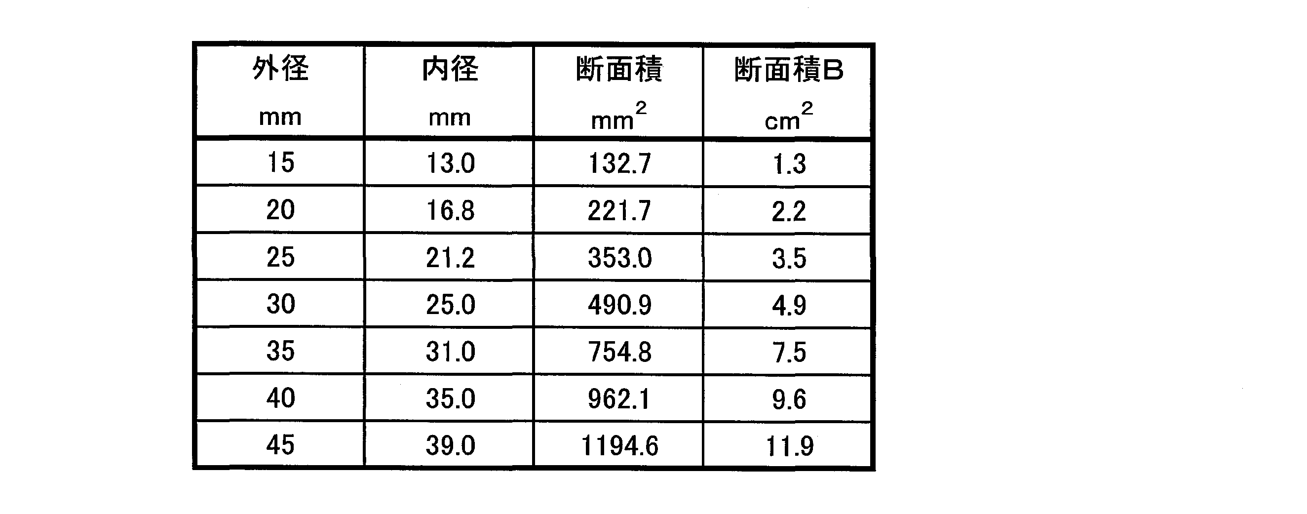
- the cross-sectional area B (cm 2 ) of the cross section perpendicular to the major axis direction of the cylindrical housing 10 in the portion of the pressurized gas chamber 30 that is in contact with the ignition means chamber 20 can be as shown in Table 1.
- the second end opening 10b between the pressurized gas chamber 30 and the diffuser portion 40 is closed with a second rupturable plate 31 made of iron, stainless steel or the like.
- the pressurized gas chamber 30 is filled with a gas such as argon or helium at a high pressure.
- the pressurized gas is sealed by welding the peripheral wall portion 11 and the pin 12 together after filling the gap between the hole and the pin 12 with the pin 12 inserted in the hole of the peripheral wall portion 11 of the cylindrical housing 10. be able to.
- the density C (g / cm 3 ) of the gas filled in the pressurized gas chamber 30 can be set as shown in Table 2.
- the diffuser portion 40 includes a bottom surface 41, a peripheral surface 42, a flange portion 43 on the opening side, and a plurality of gas discharge ports 44 formed on the peripheral surface.
- the flange 43 and the second end opening 10b of the cylindrical housing 10 are welded.
- the second rupturable plate 31 is welded to the surface of the flange portion 43 on the pressurized gas chamber 30 side.
- the igniter 23 in the ignition means chamber 20 is operated, and the gas generating agent molded body 26 is ignited and combusted to generate combustion gas.
- the first rupturable plate 24 is cleaved, and the ignition means chamber 20 and the pressurized gas chamber 30 are communicated.
- energy in the ignition means chamber 20 energy from the gas generating agent and energy from the igniting agent
- the ignition means chamber 20 and the pressurized gas chamber 30 Due to the pressure difference between them, the pressure wave advances toward the second rupturable plate 31.
- the pressure wave at this time is considered to travel as a longitudinal wave that forms a sparse / dense region of energy within the pressurized gas chamber 30, and when the dense energy part collides with the second rupturable plate 31.
- the energy is considered to increase. That is, even if the energy amount of the dense part before colliding with the second rupturable plate 31 is not so large that the second rupturable plate 31 is cleaved, a part of the energy of the wave bounced off by the second rupturable plate is energy. Since it is added to the dense portion, it is considered that the entire energy becomes larger than the burst pressure of the second rupturable plate 31 and is easily cleaved.
- the phenomenon occurs earlier than the pressure increase in the entire pressurized gas chamber due to the combustion gas from the gas generant molded body 26.
- the amount of the gas generant molded body 26 and the igniting agent is increased to increase the energy (pressure wave) A normally. Therefore, it is necessary to take measures such as improving the pressure resistance performance.
- the maximum size L1 is the length when the gas generant molded body 26 is a cylinder, and the diameter when the gas generant molded body 26 is a disk shape.
- the gas generator 1 in FIG. 2 is different from the gas generator 1 in FIG. 1 in that a cup-shaped filter 50 is disposed.
- the cup-shaped filter 50 has a bottom portion 51, a peripheral wall portion 52, and a flange portion 53 formed in the opening, and the peripheral wall portion 52 has a plurality of gas passage holes 54 penetrating in the thickness direction. .
- the gas passage hole 54 may be formed in the bottom 51.
- the flange portion 53 is fixed to the flange portion 43 of the diffuser portion 40 so that the bottom portion 51 faces the second rupturable plate 31.
- the gas generator 1 in FIG. 2 operates in the same manner as the gas generator 1 in FIG. 1, but the fragments collide with the second rupturable plate 31 even when the first rupturable plate 24 is cleaved to generate fragments. In addition, the fragments of the first rupturable plate are also prevented from entering the diffuser portion 40 after the second rupturable plate 31 is cleaved.
- the cup-shaped filter 50 can be disposed on the first rupturable plate 24 side.
- the igniting agent is a powdery composition containing ZPP, it burns instantaneously, so the time taken to complete the combustion is assumed to be 1 msec (generated energy from the igniting agent (J / g)) x (point Calculation is based on the explosive charge (g)) / 1 msec.
- the TTFG in Table 3 indicates the time from when the current is passed through the igniter until gas starts to be discharged (the time until the second rupturable plate breaks).
- the gas generator is placed in a 28.3L sealed tank. It is the numerical value calculated
- TTFG is within 2.3 msec, and gas discharge is started in a short time from the operation of the igniter.
- TTFG is taking time overall.
- Comparative Example 1 since A (J / msec) is small, it is necessary to decrease B and increase C to increase the energy control coefficient represented by the formulas (I) and (II). However, even if the energy coefficient is increased in this way, the same effect as the present invention cannot be obtained sufficiently, and the timing at which the second rupturable plate is cleaved is slightly slower than the gas generator of the specification of the embodiment. It was.
- the energy control coefficients represented by the formulas (I) and (II) are the same as those in Comparative Example 1, but the cross-sectional area B is larger than that of Comparative Example 1 and energy is easily dispersed. Therefore, it is difficult to tear the second rupturable plate.
- A, B and C energy (pressure wave) can be efficiently propagated and the second rupturable plate can be reliably destroyed.
- FIG. 3 shows the result of plotting with (A + D) / B ⁇ C on the horizontal axis and TTFG on the vertical axis.
- FIG. 4 shows the result of plotting with A / B ⁇ C on the horizontal axis and TTFG on the vertical axis.
Landscapes
- Engineering & Computer Science (AREA)
- Mechanical Engineering (AREA)
- Physics & Mathematics (AREA)
- Fluid Mechanics (AREA)
- Air Bags (AREA)
- Feeding, Discharge, Calcimining, Fusing, And Gas-Generation Devices (AREA)
Abstract
Description
エアバッグ装置に使用するガス発生器には、ガス源としてガス発生剤のみを使用するもののほか、ガス源として主としてアルゴン、ヘリウムなどが高圧充填されたものを使用するものがある。
アルゴンやヘリウムなどが高圧充填されたタイプのガス発生器の場合には、作動前の状態では、ガスが高圧充填された加圧ガス室と、前記加圧ガス室内のガスの排出口との間のガス排出経路が破裂板で閉塞されており、作動時には、前記破裂板が破壊されてガス排出経路が開放されることでガスが排出されるようになっている。
図1に示されているとおり、インフレータ1は、ハウジング3の一端側に破裂板14で閉塞されたスクイブ側口金部9があり、反対側端部に破裂板13で閉塞された吐出側口金部7を有しており、中間部分に加圧ガスG0が充填されている。
JP-A No.2014-69628のインフレータでは、ガス発生剤11は、燃焼時に発生する燃焼ガスを、加圧ガスG0とともに、エアバッグの膨張用に使用可能とされるもので、具体的には、燃焼時の発熱量を、6000~10000J/gの範囲内に設定されているものを使用すると記載されている(段落番号0014)。
またJP-A No.2014-69628には、「実施形態のインフレーター1では、加圧ガスG0と、ガス発生剤11と、が、加圧ガスとガス発生剤11が燃焼して発生する燃焼ガスとのモル比(加圧ガス/燃焼ガス)を、80~130の範囲内とするように、内部に充填されている。」と記載されている(段落番号0016)。
そして、実施形態のインフレーター1では、「スクイブ10が作動して、ガス発生剤11が燃焼して燃焼ガスが発生し、発生した燃焼ガスによってスクイブ側口金部9の内圧が高まれば、破裂板14が破裂して、ハウジング3内に燃焼ガスが流入することとなる。そして、この燃焼ガスによってハウジング3内の加圧ガスG0が加熱され、ハウジング3の内圧が高まれば、破裂板13が破裂して、加圧ガスG0と燃焼ガスとが、膨張用ガスGとして、吐出側口金部7に設けられたガス吐出口7bからインフレーター1外へ流出することとなり、エアバッグ装置のエアバッグを膨張させることとなる。」(段落番号0017)と記載されている。
つまり、加圧ガスG0部分の圧力が上昇することで、破裂板13が破裂して、吐出側口金部7を通って、ガス排出口7bからガスが排出されるものである。
「イニシエータ充填剤が着火すると、それが衝撃波を発生し、その衝撃波がインフレータ筐体の第1の端部から移動し、貯蔵ガスの入った障害物のないインフレータ筐体を通って、バーストディスクおよびインフレータ筐体の第2の端部に至る。衝撃波がバーストディスクに達すると、その衝撃波はバーストディスクから反射する。バーストディスクから反射すると、バーストディスクと衝撃波の間で圧力が上昇する。この発生した圧力は、バーストディスクのバースト圧より高いために、バーストディスクの開放または破裂が起こる。開放後、貯蔵ガスおよびイニシエータ充填剤および/ または他の推進剤の活性化によって発生したガスによるインフレータ筐体中の膨張ガスは、開放したバーストディスクから流出する。」(段落番号0011)
JP-A No.2003-520153の発明では、JP-A No.2014-69628の発明のようにガス放出口側にある破裂板を破壊する手段として、ガス発生剤の燃焼ガスは使用していない。
本発明の第1の実施態様は、筒状ハウジングの第1端開口部側に点火手段室を有し、長軸方向反対側の第2端開口部側にガス排出口を有するディフューザ部を有し、前記点火手段室と前記ディフューザ部の間に加圧ガス室を有しているガス発生器であって、
前記点火手段室と前記加圧ガス室の間の第1端開口部が第1破裂板で閉塞され、前記加圧ガス室と前記ディフューザ部の間の第2端開口部が第2破裂板で閉塞されており、
前記点火手段室内には点火器とガス発生剤成形体が収容されており、
前記加圧ガス室内にはガス源となるガスが充填されており、
前記点火手段室内に充填されているガス発生剤成形体から発生する単位時間当たりのエネルギー量A(J/msec)と、
前記加圧ガス室の前記点火手段室と接する部分の筒状ハウジング長軸方向に直交する断面の断面積B(cm2)と、
前記加圧ガス室に充填されたガスの密度C(g/cm3)が、
次式(I):A/B×C=320~490 (I)で示されるエネルギー制御係数を満たしているものである、ガス発生器を提供する。
前記点火手段室と前記加圧ガス室の間の第1端開口部が第1破裂板で閉塞され、前記加圧ガス室と前記ディフューザ部の間の第2端開口部が第2破裂板で閉塞されており、
前記点火手段室内には点火薬を含む点火器とガス発生剤成形体が収容されており、
前記加圧ガス室内にはガス源となるガスが充填されており、
前記点火手段室内に充填されているガス発生剤成形体から発生する単位時間当たりのエネルギー量A(J/msec)と、
前記点火器から発生する単位時間当たりのエネルギー量D(J/msec)と、
前記加圧ガス室の前記点火手段室と接する部分の筒状ハウジング長軸方向に直交する断面の断面積B(cm2)と、
前記加圧ガス室に充填されたガスの密度C(g/cm3)が、
次式(II):(A+D)/B×C=430~580 (II)で示されるエネルギー制御係数を満たしているものである、ガス発生器を提供する。
本発明は、より小さなエネルギーにてガス排出経路を閉塞している破裂板を破壊することができるガス発生器を提供する。
第1破裂板の開裂により生じた開口部から放出されたエネルギーは、加圧ガス室内を移動して第2破裂板に衝突して開裂させ、加圧ガス室からディフューザ部へのガス排出口を開口させる。
第2破裂板の開口部を通ったガスは、ディフューザ部のガス排出口から排出される。
本発明のガス発生器では、ガス発生剤による燃焼ガスが、加圧ガス室全体の圧力を増大させることによって第2破裂板が開裂するのではなく、それよりも早いタイミングでガス発生剤から発生したエネルギーで圧力波を発生させ、その圧力波が加圧ガスを伝播して第2破裂板を開裂させる。
したがって、ガス発生器からのガスの排出を迅速に行うことができる。この圧力波は、点火手段室で発生したエネルギーが加圧ガス室へ流れ込むときに、両室の間に発生する大きなエネルギー差に起因するものと考えられる。そのため、ガス発生剤からのエネルギー量は、短時間のうちにある程度の量を発生し、加圧ガス室と点火手段室との間に圧力の差を形成する必要がある。なおここでいう圧力波とは、音速以下の速度で伝播する波を表す。
このような動作をする本発明のガス発生器は、ガス発生剤成形体と加圧ガスを使用するハイブリッドタイプのガス発生器であり、式(I)のエネルギー制御係数を満たしていることによって、次の動作(a)、(b)、(c)ができることが特徴の発明である。
(a)加圧ガス室とディフューザ部の間を閉塞している第2破裂板を開裂させるための点火手段から発生させるエネルギー量を抑制できること。
(b)点火手段室内で発生したエネルギーが加圧ガス室内を通過するときのエネルギーの減衰をできるだけ小さくして第2破裂板まで到達させて開裂させること。
(c)発生エネルギー量、加圧ガスの充填密度を適正範囲に維持することで、ガス発生器自体の質量を抑制できること。
(1)ガス発生器に充填するガス発生剤成形体を所定の形状に成型したものを準備する。使用するガス発生剤成形体の組成や組成比、形状、寸法は公知のものを用いることができる。
ガス発生剤成形体をガス発生器に充填して作動させたときに、当該ガス発生剤成形体が配置された点火手段室の圧力が、最大値に到達するまでの時間(T/ msec)、および最大圧力値(P/ kPa)を測定する。ここでTは、その時点で閉塞部材(第1破裂板)が開裂したことを示す。
この測定を複数の異なった圧力下で行い、ガス発生剤成形体の圧力指数nを求める。(r=a×Pn)(ただしaは定数)
(4)上記(3)で求めた圧力P1/2での燃焼速度rを上記(2)の式から求める。
(5)上記(1)のガス発生剤成形体が上記(4)で求めた燃焼速度でハウジング内圧が最大値に到達するまでの時間に燃焼した質量(g)を求める。
(6)ガス発生器に充填する全ガス発生剤成形体から発生するエネルギーを所定の機器で測定し、充填したガス発生剤成形体の充填量で割り、単位重量当たりの発生エネルギー(J/g)を求める。
(7)上記(5)、(6)を掛け合わせて全体のエネルギー量を求める(J/mol)。
筒状ハウジングが均一径(均一内径)であるときは、式(I)中のBは長さ方向の任意の位置の断面積となる。
筒状ハウジングの断面積は、ガス発生剤成型体からのエネルギーを分散させる要件になることから、筒状ハウジングが均一内径でない場合には、筒状ハウジングの内径が最大になる部分(すなわち断面積が最大になる部分)を式(I)中のBとする。
よって、A/Bは、単位断面積あたりのエネルギー量(発生したエネルギーがどれだけの加圧ガスに仕事を与えるのかという尺度)を表すことになる。
Cは、加圧ガス室内に発生したエネルギー(圧力波)をできるだけ減衰させないようにして第2破裂板まで伝えるための要件である。
加圧ガス室内の加圧ガスの充填密度が高いほどエネルギー(圧力波)の減衰は少なくなり、前記充填密度が低いほど減衰は大きくなる。即ち、第2破裂板に対して効率的にエネルギーを供給するためには、エネルギーが第2破裂板に伝わっていく間にエネルギーの消費を可能な限り抑制することが望ましい。なお、充填圧力は同じであってもガスの種類によって密度は変わってくる。
このため、燃焼ガスによるモル数の増加を考慮したときには、式(I)中のCは、C×(E+F)/E(Eは加圧ガスのモル数、Fはガス発生剤成形体から発生するガス(燃焼ガス)のモル数)で表すこともできる。
式(I)のエネルギー制御係数(下限値)が320未満であるときは、A(J/msec)が小さくなるか、Bが大きくなるか、またはCのガス密度が小さくなる。
A(J/msec)が小さくなったり、Bが大きくなったり、Cが小さくなったりすると、発生するエネルギー(圧力波)が小さくなったり、圧力波の伝播力が小さくなったりして、第2破裂板を開裂させることが困難になる。
式(I)のエネルギー制御係数(上限値)が490を超えるときは、A(J/msec)が大きくなるか、Bが小さくなるか、またはCのガス密度が大きくなる。
この場合には、作動時における発生エネルギーが非常に高くなるため、筒状ハウジングの肉厚を大きくして発生エネルギーへの耐性を高めるなどの対策を講じる必要があり、ガス発生器自体の質量が増加してしまう。
式(II)のエネルギー制御係数(下限値)が430未満であるときは、A+D(J/msec)が小さくなるか、Bが大きくなるか、またはCのガス密度が小さくなる。
A+D(J/msec)が小さくなったり、Bが大きくなったり、Cが小さくなったりすると、発生するエネルギー(圧力波)が小さくなったり、圧力波の伝播力が小さくなったりして、第2破裂板を開裂させることが困難になる。
式(I)のエネルギー制御係数(上限値)が580を超えるときは、A+D(J/msec)が大きくなるか、Bが小さくなるか、またはCのガス密度が大きくなる。
この場合には、作動時における発生エネルギーが非常に高くなるため、筒状ハウジングの肉厚を大きくして発生エネルギーへの耐性を高めるなどの対策を講じる必要があり、ガス発生器自体の質量が増加してしまう。
前記カップ状のフィルタが、底部、周壁部および開口部を有しており、さらに少なくとも前記周壁部が厚さ方向に貫通した複数のガス通過孔を有しているものであり、
前記カップ状のフィルタが、前記底部が前記第1破裂板または第2破裂板と対向するように、前記開口部が前記ディフューザ部に対して固定されているものである。
なお、第1破裂板側または第2破裂板側にカップ状フィルタを配置した場合でも、圧力波により開裂される第2破裂板の開裂動作が阻害されることはない。例えば筒状ハウジングの第2端開口部の内径を徐々に縮径させて、圧力波を反射させてカップ状のフィルタにおけるガス通過孔に集中しやすくすることが出来る。
(1)図1のガス発生器
ガス発生器1は、筒状ハウジング10の第1端開口部10a側に点火手段室20を有しており、長軸方向反対側の第2端開口部10b側にディフューザ部40を有している。
筒状ハウジング10、点火手段室20、ディフューザ部40は、いずれも鉄、ステンレスなどの金属からなるものであり、それぞれの接続箇所は溶接されている。
点火手段室20とディフューザ部40の間には、加圧ガス室30を有している。
第1破裂板24は、筒状の点火手段室ハウジング21の第2端開口部21b側に周縁部が溶接固定されている。
点火手段室20の内部には、公知のガス発生剤成形体26が充填されている。
加圧ガス室30の点火手段室20と接する部分の筒状ハウジング10の長軸方向に直交する断面の断面積B(cm2)は、表1に示すようにすることができる。
加圧ガス室30内には、アルゴン、ヘリウムなどのガスが高圧で充填されている。加圧ガスは、筒状ハウジング10の周壁部11の孔にピン12を差し込んだ状態で、孔とピン12の隙間から充填した後、周壁部11とピン12を一緒に溶接することで封入することができる。
加圧ガス室30に充填されたガスの密度C(g/cm3)は、表2に示すようにすることができる。

フランジ部43と筒状ハウジング10の第2端開口部10bが溶接されている。
第2破裂板31は、フランジ部43の加圧ガス室30側の面に溶接されている。
点火手段室20内の点火器23が作動してガス発生剤成形体26が着火燃焼され、燃焼ガスを発生させる。
燃焼ガスの発生により点火手段室20内の圧力が高められると、第1破裂板24が開裂して、点火手段室20と加圧ガス室30が連通される。
点火手段室20内のエネルギー(ガス発生剤からのエネルギー、および点火薬からのエネルギー)が連通口から加圧ガス室30内に放出されると、点火手段室20と加圧ガス室30との間の圧力差に起因して、圧力波が第2破裂板31方向に進む。
このときの圧力波は、加圧ガス室30内部にエネルギーの疎/密の領域を形成する縦波として進行するものと考えられ、エネルギーが密の部分が第2破裂板31に衝突したときに、そのエネルギーが増大するものと考えられる。
つまり、第2破裂板31に衝突する前の密の部分のエネルギー量が、第2破裂板31を開裂させるほど大きくなくても、第2破裂板で跳ね返った波のエネルギーの一部がエネルギーの密な部分に加わることから、エネルギー全体が第2破裂板31の破裂圧より大きくなり、開裂し易くなるものと考えられる。そしてその現象が、ガス発生剤成形体26からの燃焼ガスによる加圧ガス室全体の圧力上昇よりも早く発生する。
このように開裂させる場合、通常であれば単にエネルギー(圧力波)Aを大きくするために、ガス発生剤成形体26や点火薬の量を増量することになるが、これはガス発生剤成形体26や点火薬全体から過剰なエネルギーを発生させることとなるため、耐圧性能を向上させるなどの措置を講ずる必要がある。
本発明のガス発生器1は、式(I):A/B×C=320~490、または式(II):(A+D)/B×C=430~580のエネルギー制御係数を満たしていることが特徴であるため、Aを過剰に大きくしなくても(すなわち、ある程度のエネルギーを瞬時に発生できる状態であれば)、BとCを調整することで、第2破裂板31を開裂させることができる。
ここで、最大大きさL1は、ガス発生剤成形体26が円柱のときは長さであり、ガス発生剤成形体26がディスク形状のときは直径である。
図2のガス発生器1は、図1のガス発生器1に対してカップ状のフィルタ50を配置しただけの違いである。
カップ状のフィルタ50は、底部51、周壁部52および開口部に形成されたフランジ部53を有しており、周壁部52は厚さ方向に貫通した複数のガス通過孔54を有している。ガス通過孔54は、底部51に形成されていてもよい。
カップ状のフィルタ50は、底部51が第2破裂板31と対向するように、フランジ部53がディフューザ部40のフランジ部43に対して固定されている。
図1に示すガス発生器1を使用して、例ごとにA、B、C、Dを表3に示すように調整した。なお、点火薬はZPPを含む組成でパウダー状のものであるため瞬時に燃焼するので、その燃焼完了にかかる時間を1 msecとして、(点火薬からの発生エネルギー(J/g))×(点火薬充填量(g))/1 msecで計算をしている。また表3のTTFGは、点火器に電流を流してからガスが排出開始されるまでの時間(第2破裂板が開裂するまでの時間)を指すもので、ガス発生器を28.3L密閉タンク内に配置して、室温で作動させたときのタンク内部圧力曲線から求めた数値である。
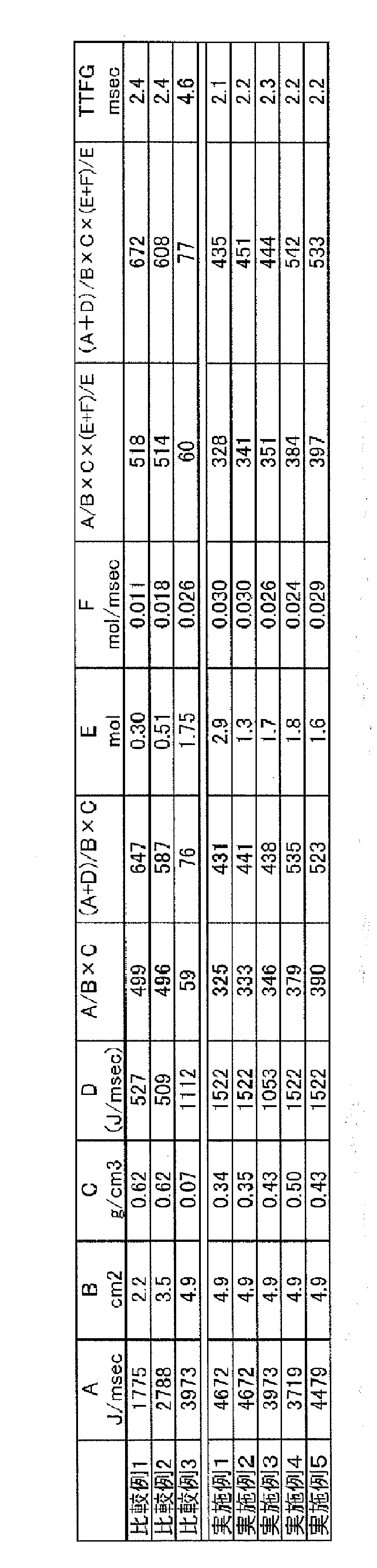
比較例1~3は、式(I)の値が59,496、499であり、式(I):A/B×C=320~490からはずれていた。また式(II)の値が76、587、647であり、式(II):(A+D)/B×C=430~580から外れている。そしてTTFGも全体的に時間がかかっている。
比較例2は、式(I)、(II)で示されるエネルギー制御係数は比較例1と変わらないが、比較例1よりも断面積Bが大きくなり、エネルギーが分散しやすくなっているので効率的に第2破裂板を開裂しにくい。
比較例3は、A(J/msec)が大きいため、Bを大きくして、Cを小さくせざるを得ず、第2破裂板を開裂するに十分な式(I)、(II)で示されるエネルギー制御係数を得ることができなくなる。
Claims (3)
- 筒状ハウジングの第1端開口部側に点火手段室を有し、長軸方向反対側の第2端開口部側にガス排出口を有するディフューザ部を有し、前記点火手段室と前記ディフューザ部の間に加圧ガス室を有しているガス発生器であって、
前記点火手段室と前記加圧ガス室の間の第1端開口部が第1破裂板で閉塞され、前記加圧ガス室と前記ディフューザ部の間の第2端開口部が第2破裂板で閉塞されており、
前記点火手段室内には点火器とガス発生剤成形体が収容されており、
前記加圧ガス室内にはガス源となるガスが充填されており、
前記点火手段室内に充填されているガス発生剤成形体から発生する単位時間当たりのエネルギー量A(J/msec)と、
前記加圧ガス室の前記点火手段室と接する部分の筒状ハウジング長軸方向に直交する断面の断面積B(cm2)と、
前記加圧ガス室に充填されたガスの密度C(g/cm3)が、
次式(I):A/B×C=320~490 (I)で示されるエネルギー制御係数を満たしているものである、ガス発生器。 - 筒状ハウジングの第1端開口部側に点火手段室を有し、長軸方向反対側の第2端開口部側にガス排出口を有するディフューザ部を有し、前記点火手段室と前記ディフューザ部の間に加圧ガス室を有しているガス発生器であって、
前記点火手段室と前記加圧ガス室の間の第1端開口部が第1破裂板で閉塞され、前記加圧ガス室と前記ディフューザ部の間の第2端開口部が第2破裂板で閉塞されており、
前記点火手段室内には点火薬を含む点火器とガス発生剤成形体が収容されており、
前記加圧ガス室内にはガス源となるガスが充填されており、
前記点火手段室内に充填されているガス発生剤成形体から発生する単位時間当たりのエネルギー量A(J/msec)と、
前記点火器から発生する単位時間当たりのエネルギー量D(J/msec)と
前記加圧ガス室の前記点火手段室と接する部分の筒状ハウジング長軸方向に直交する断面の断面積B(cm2)と、
前記加圧ガス室に充填されたガスの密度C(g/cm3)が、
次式(II):(A+D)/B×C=430~580 (II)で示されるエネルギー制御係数を満たしているものである、ガス発生器。 - 前記第1破裂板または第2破裂板が前記加圧ガス室側からカップ状のフィルタで覆われており、
前記カップ状のフィルタが、底部、周壁部および開口部を有しており、さらに少なくとも前記周壁部が厚さ方向に貫通した複数のガス通過孔を有しているものであり、
前記カップ状のフィルタが、前記底部が前記第1破裂板または第2破裂板と対向するように、前記開口部が前記ディフューザ部に対して固定されているものである、請求項1または2記載のガス発生器。
Priority Applications (5)
| Application Number | Priority Date | Filing Date | Title |
|---|---|---|---|
| US16/064,315 US10589710B2 (en) | 2016-01-25 | 2017-01-24 | Gas generator |
| DE112017000485.3T DE112017000485B4 (de) | 2016-01-25 | 2017-01-24 | Gasgenerator |
| CN201780006433.XA CN108602486B (zh) | 2016-01-25 | 2017-01-24 | 气体发生器 |
| JP2017564254A JP6707095B2 (ja) | 2016-01-25 | 2017-01-24 | ガス発生器 |
| KR1020187018925A KR102580661B1 (ko) | 2016-01-25 | 2017-01-24 | 가스 발생기 |
Applications Claiming Priority (2)
| Application Number | Priority Date | Filing Date | Title |
|---|---|---|---|
| JP2016-011367 | 2016-01-25 | ||
| JP2016011367 | 2016-01-25 |
Publications (1)
| Publication Number | Publication Date |
|---|---|
| WO2017130935A1 true WO2017130935A1 (ja) | 2017-08-03 |
Family
ID=59398255
Family Applications (1)
| Application Number | Title | Priority Date | Filing Date |
|---|---|---|---|
| PCT/JP2017/002253 Ceased WO2017130935A1 (ja) | 2016-01-25 | 2017-01-24 | ガス発生器 |
Country Status (6)
| Country | Link |
|---|---|
| US (1) | US10589710B2 (ja) |
| JP (1) | JP6707095B2 (ja) |
| KR (1) | KR102580661B1 (ja) |
| CN (1) | CN108602486B (ja) |
| DE (1) | DE112017000485B4 (ja) |
| WO (1) | WO2017130935A1 (ja) |
Cited By (1)
| Publication number | Priority date | Publication date | Assignee | Title |
|---|---|---|---|---|
| CN112881229A (zh) * | 2021-01-06 | 2021-06-01 | 西北工业大学 | 一种固体推进剂高压熄火燃面获取装置及获取方法 |
Families Citing this family (1)
| Publication number | Priority date | Publication date | Assignee | Title |
|---|---|---|---|---|
| CN114523932B (zh) * | 2022-03-15 | 2023-04-28 | 湖北航天化学技术研究所 | 整体式点火结构和压缩气体式燃气发生器 |
Citations (2)
| Publication number | Priority date | Publication date | Assignee | Title |
|---|---|---|---|---|
| JP2003520153A (ja) * | 1999-12-09 | 2003-07-02 | オートリブ エーエスピー インコーポレイテッド | バーストディスクを開放する衝撃波を発生させる車両用インフレータ |
| JP2014069628A (ja) * | 2012-09-28 | 2014-04-21 | Toyoda Gosei Co Ltd | インフレーター |
Family Cites Families (13)
| Publication number | Priority date | Publication date | Assignee | Title |
|---|---|---|---|---|
| US5884938A (en) * | 1996-04-15 | 1999-03-23 | Autoliv Asp Inc. | Pressurized fluid containing airbag inflator |
| EP1314622A4 (en) * | 2000-08-29 | 2006-08-09 | Daicel Chem | inflation |
| EP1867532B1 (en) * | 2001-11-30 | 2012-02-29 | Daicel Chemical Industries, Ltd. | Inflator |
| US7134689B2 (en) * | 2001-11-30 | 2006-11-14 | Daicel Chemical Industries, Ltd. | Inflator |
| JP4062037B2 (ja) * | 2001-12-25 | 2008-03-19 | タカタ株式会社 | インフレータ及びエアバッグ装置 |
| JP4209184B2 (ja) * | 2002-06-05 | 2009-01-14 | ダイセル化学工業株式会社 | インフレータ |
| US7665764B2 (en) | 2004-01-15 | 2010-02-23 | Daicel Chemical Industries, Ltd. | Gas generator for air bag |
| JP4494023B2 (ja) * | 2004-01-15 | 2010-06-30 | ダイセル化学工業株式会社 | エアバッグ用ガス発生器 |
| JP2006007815A (ja) * | 2004-06-22 | 2006-01-12 | Takata Corp | インフレータ及びエアバッグ装置 |
| JP2006160049A (ja) * | 2004-12-07 | 2006-06-22 | Daicel Chem Ind Ltd | エアバッグ用小型インフレータ |
| JP2006218990A (ja) * | 2005-02-10 | 2006-08-24 | Daicel Chem Ind Ltd | 乗員拘束装置用ガス発生器 |
| JP4916855B2 (ja) * | 2006-12-01 | 2012-04-18 | 株式会社ダイセル | インフレータ |
| EP2471692B2 (en) * | 2009-05-11 | 2022-01-05 | Joyson Safety Systems Germany GmbH | Gas generator for inflating a gas bag of a vehicle occupant restraint system and method of inflating a gas bag |
-
2017
- 2017-01-24 DE DE112017000485.3T patent/DE112017000485B4/de active Active
- 2017-01-24 CN CN201780006433.XA patent/CN108602486B/zh active Active
- 2017-01-24 JP JP2017564254A patent/JP6707095B2/ja active Active
- 2017-01-24 KR KR1020187018925A patent/KR102580661B1/ko active Active
- 2017-01-24 WO PCT/JP2017/002253 patent/WO2017130935A1/ja not_active Ceased
- 2017-01-24 US US16/064,315 patent/US10589710B2/en active Active
Patent Citations (2)
| Publication number | Priority date | Publication date | Assignee | Title |
|---|---|---|---|---|
| JP2003520153A (ja) * | 1999-12-09 | 2003-07-02 | オートリブ エーエスピー インコーポレイテッド | バーストディスクを開放する衝撃波を発生させる車両用インフレータ |
| JP2014069628A (ja) * | 2012-09-28 | 2014-04-21 | Toyoda Gosei Co Ltd | インフレーター |
Cited By (2)
| Publication number | Priority date | Publication date | Assignee | Title |
|---|---|---|---|---|
| CN112881229A (zh) * | 2021-01-06 | 2021-06-01 | 西北工业大学 | 一种固体推进剂高压熄火燃面获取装置及获取方法 |
| CN112881229B (zh) * | 2021-01-06 | 2022-12-06 | 西北工业大学 | 一种固体推进剂高压熄火燃面获取装置及获取方法 |
Also Published As
| Publication number | Publication date |
|---|---|
| JPWO2017130935A1 (ja) | 2018-11-15 |
| DE112017000485T5 (de) | 2018-10-31 |
| US20190001918A1 (en) | 2019-01-03 |
| KR102580661B1 (ko) | 2023-09-21 |
| DE112017000485B4 (de) | 2024-03-07 |
| US10589710B2 (en) | 2020-03-17 |
| CN108602486B (zh) | 2021-05-04 |
| KR20180103052A (ko) | 2018-09-18 |
| CN108602486A (zh) | 2018-09-28 |
| JP6707095B2 (ja) | 2020-06-10 |
Similar Documents
| Publication | Publication Date | Title |
|---|---|---|
| US3773351A (en) | Gas generator | |
| US5005486A (en) | Igniter for airbag propellant grains | |
| US6155600A (en) | Safety air bag inflation device | |
| US5951043A (en) | Air bag inflator using liquid monopropellant and adaptable to produce outputs with various parameters | |
| JP4167284B2 (ja) | 多段式インフレータ | |
| JPH05278554A (ja) | 車両搭乗者拘束具 | |
| JPH1071922A (ja) | ガス発生器 | |
| US8656838B1 (en) | Secondary chamber combustion control | |
| CN109963826B (zh) | 具有作为燃料的泡沫的混合式充气机 | |
| JP2004042893A (ja) | 低強度二段式ハイブリッドインフレータ | |
| JPH0858520A (ja) | 乗物搭乗者用の膨張可能な拘束手段の膨張装置 | |
| US3786843A (en) | Delayed filling of air bag | |
| US6007097A (en) | Flammable gas initiated pyrotechnic inflator | |
| WO2023174313A1 (zh) | 整体式点火结构和压缩气体式燃气发生器 | |
| CN102667395A (zh) | 使用反应性气体的气体发生器 | |
| JP6707095B2 (ja) | ガス発生器 | |
| CN105492113B (zh) | 气体发生器 | |
| CN105579302A (zh) | 破裂板及使用其的充气机 | |
| JP2005238948A (ja) | 破裂部材 | |
| CN110520334A (zh) | 气体发生器 | |
| US20050189750A1 (en) | Hybrid inflator | |
| US6607214B2 (en) | Gas generation via indirect ignition | |
| US20080069740A1 (en) | Gas generator for restraining device of vehicle | |
| US6289814B1 (en) | Heat source for airbag inflation gas generation via a dissociating material | |
| CN110770089B (zh) | 气体发生器 |
Legal Events
| Date | Code | Title | Description |
|---|---|---|---|
| 121 | Ep: the epo has been informed by wipo that ep was designated in this application |
Ref document number: 17744165 Country of ref document: EP Kind code of ref document: A1 |
|
| ENP | Entry into the national phase |
Ref document number: 2017564254 Country of ref document: JP Kind code of ref document: A |
|
| ENP | Entry into the national phase |
Ref document number: 20187018925 Country of ref document: KR Kind code of ref document: A |
|
| WWE | Wipo information: entry into national phase |
Ref document number: 112017000485 Country of ref document: DE |
|
| 122 | Ep: pct application non-entry in european phase |
Ref document number: 17744165 Country of ref document: EP Kind code of ref document: A1 |