WO2017130394A1 - 始動発電装置および始動発電方法 - Google Patents
始動発電装置および始動発電方法 Download PDFInfo
- Publication number
- WO2017130394A1 WO2017130394A1 PCT/JP2016/052753 JP2016052753W WO2017130394A1 WO 2017130394 A1 WO2017130394 A1 WO 2017130394A1 JP 2016052753 W JP2016052753 W JP 2016052753W WO 2017130394 A1 WO2017130394 A1 WO 2017130394A1
- Authority
- WO
- WIPO (PCT)
- Prior art keywords
- winding
- voltage
- stage
- power
- multiphase winding
- Prior art date
- Legal status (The legal status is an assumption and is not a legal conclusion. Google has not performed a legal analysis and makes no representation as to the accuracy of the status listed.)
- Ceased
Links
Images












Classifications
-
- H—ELECTRICITY
- H02—GENERATION; CONVERSION OR DISTRIBUTION OF ELECTRIC POWER
- H02P—CONTROL OR REGULATION OF ELECTRIC MOTORS, ELECTRIC GENERATORS OR DYNAMO-ELECTRIC CONVERTERS; CONTROLLING TRANSFORMERS, REACTORS OR CHOKE COILS
- H02P6/00—Arrangements for controlling synchronous motors or other dynamo-electric motors using electronic commutation dependent on the rotor position; Electronic commutators therefor
- H02P6/14—Electronic commutators
- H02P6/16—Circuit arrangements for detecting position
Definitions
- the present invention relates to a starting power generation device and a starting power generation method.
- a three-phase DC brushless motor has been used in an ACG (AC generator) starter motor that functions as a starter motor when starting an engine and a generator after starting the engine in a vehicle, particularly a small motorcycle. 1).
- ACG AC generator
- a hall sensor is provided corresponding to each phase winding of the three-phase winding, and the position of the rotor is detected using the hall sensor. We were detecting.
- Patent Document 2 a technique for detecting the position of the rotor without using a Hall sensor has been developed (Patent Document 2).
- Patent Document 2 when the brushless motor is stopped, a plurality of patterns of DC voltages are applied to two of the three-phase windings for a short time, and changes according to the rotor position. The stop position of the rotor was detected by measuring the rising characteristics of the current to be generated.
- JP 2003-83209 A Japanese Patent No. 4801772
- control device described in Patent Document 2 requires a circuit for detecting the current flowing in the winding.
- the current detection circuit tends to have a more complicated configuration or a larger loss than the voltage detection circuit. For this reason, the control device described in Patent Document 2 has problems that it is difficult to reduce the size or to reduce the price.
- An object of the present invention is to provide a starting power generation device and a starting power generation method that can solve the above-described problems.
- an aspect of the starting power generation device is an armature in which a field portion made of a permanent magnet, a first multiphase winding, and a second multiphase winding are arranged in parallel. And a first positive DC terminal connected to the battery, and a plurality of first AC terminals connected to the first multiphase winding, both between DC and AC A first power conversion unit that converts power in a direction and a plurality of second AC terminals connected to the second multiphase winding, and controls a current that is input and output via the second AC terminal.
- the second multi-path detected when a predetermined line voltage is applied by sequentially selecting a plurality of energization patterns determined by the winding set and the direction of voltage application in the first multi-phase winding in the off state.
- the comparison result is a result of comparing the magnitudes of the absolute values of the phase voltages in the starting power generation device.
- one aspect of the starter power generation method of the present invention is a starter generator having a field part made of a permanent magnet and an armature part in which a first multiphase winding and a second multiphase winding are arranged in parallel.
- a first positive-side DC terminal connected to the battery and a plurality of first AC terminals connected to the first multiphase winding, and bidirectionally converts power between DC and AC
- Based on the output voltage of the second multiphase winding a positional relationship between the field magnet portion and the armature portion is detected, and the first power conversion unit and the second power conversion unit are detected according to the detected positional relationship.
- control unit is configured to turn off the current input / output via the second AC terminal.
- Phase voltage of the second multiphase winding detected when a plurality of energization patterns determined by the winding group and the direction of voltage application in the first multiphase winding are sequentially selected and a predetermined line voltage is applied.
- the comparison of the phase voltages of the plurality of different phases of the second multiphase winding detected when the line voltage is applied with different energization patterns The positional relationship at the time is detected.
- the rotor stop position is detected by detecting the phase voltage generated in the second multiphase winding. Can be determined. According to this, current detection can be made unnecessary.
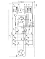
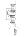
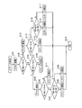
- FIG. 2 is a circuit diagram for explaining an internal configuration of a first power conversion unit 61, a second power conversion unit 62, and a control unit 7 shown in FIG. 3 is a flowchart showing an example of starter motor start control of the start power generation control device 100 shown in FIG. 1.
- FIG. 3 is a flowchart showing an example of power generation control of the start power generation control device 100 shown in FIG. 1. It is a wave form diagram for demonstrating the process (S22) shown in FIG. It is a circuit diagram for demonstrating the structure of the 2nd Embodiment of this invention. It is a circuit diagram for demonstrating the structure of the 3rd Embodiment of this invention.
- FIG. 1 is a block diagram illustrating a configuration example of a starting power generation control device 100 according to an embodiment of the present invention.
- the starting power generation control device 100 shown in FIG. 1 includes a starting generator (ACG starter motor) 1, a first power conversion unit 61, a second power conversion unit 62, and a control unit 7.
- the starter generator 1 is directly connected to the crankshaft 3 and rotates in synchronization with the rotation of the engine 2.
- the first power converter 61, the second power converter 62, and the controller 7 are connected to the positive electrode of the battery 9 and grounded.
- the battery 9 is a secondary battery whose negative electrode is grounded.
- the starter switch 8 is a switch that is operated when the user starts the engine 2.
- the output of the engine water temperature gauge 5 is connected to the control unit 7.
- the starter generator 1 operates as a starter motor or operates as a generator under the control of the first power converter 61 and the second power converter 62.
- the starter generator 1 includes a winding part ACG1, a winding part ACG2, and a field part 15 shown in FIG.
- Winding portion ACG1 includes windings U1, V1, and W1 that constitute a star-connected three-phase winding (multi-phase winding).
- Winding portion ACG2 includes windings U2, V2, and W2 that constitute a star-connected three-phase winding.
- the neutral point N1 is a neutral point of the star connection constituting the winding part ACG1.
- the neutral point N2 is a neutral point of star connection constituting the winding part ACG2.
- Windings U1, V1, and W1 and windings U2, V2, and W2 are a set of armature windings that are wound around the same armature core (not shown) and are electrically insulated. .
- Winding portion ACG1 and winding portion ACG2 and an armature core (not shown) constitute an armature portion.
- Winding portion ACG1 and winding portion ACG2 are not limited to star connection, and may be configured by delta connection.
- FIG. 2 is a diagram schematically showing a configuration example of the winding part ACG1, the winding part ACG2 and the field part 15 of the starter generator 1 as viewed from the axial direction.
- FIG. 2 shows only the winding U1 and the winding U2.
- the starter generator 1 is an outer rotor type brushless motor in which the field magnet portion 15 includes a plurality of sets of N-pole permanent magnets 15N and S-pole permanent magnets 15S.
- the field portion 15 is also referred to as a rotor.
- the winding U1 is composed of three windings U1-1, U1-2 and U1-3 arranged at intervals of 120 degrees with respect to an armature core (not shown).
- each of the three windings U1-1, U1-2, and U1-3 of the winding U1 is commonly connected to the neutral point N1, and each other end is commonly connected to the input / output terminal of the winding U1.
- the winding U2 has three windings U2- disposed at intervals of 120 degrees with respect to an armature core (not shown) and shifted by 60 degrees with respect to the windings U1-1, U1-2 and U1-3. 1, U2-2 and U2-3.
- the three windings U2-1, U2-2 and U2-3 of the winding U2 have one end commonly connected to the neutral point N2 and the other end commonly connected to the input / output terminal of the winding U2. ing.
- the input / output terminal of the winding U1 that is a terminal opposite to the neutral point N1 or the neutral point N2 or The input / output terminal of the winding U2 is indicated.
- the winding U1, the winding U2, the winding V1, the winding W1, the winding V2, the winding W2, the neutral point N1, and the neutral point N2 are simply denoted by reference numerals U1, U2, V1, W1, V2, W2, and W2. , N1 and N2.
- the engine 2 is a motor mounted on, for example, a small motorcycle.
- the crankshaft 3 is a component part of the engine 2 and is an axis that converts a reciprocating motion of a piston (not shown) included in the engine 2 into a rotational motion.
- the engine water temperature gauge 5 is a sensor that detects the temperature of the cooling water of the engine 2.
- the first power conversion unit 61 includes six n-channel MOSFETs (metal oxide semiconductor field effect transistors, hereinafter referred to as MOSFETs (switch elements)) (Q1) to (Q6).
- MOSFETs metal oxide semiconductor field effect transistors
- Q1 to Q6 n-channel MOSFETs (metal oxide semiconductor field effect transistors, hereinafter referred to as MOSFETs (switch elements)) (Q1) to (Q6).
- a three-phase bridge orthogonal transform circuit multi-phase bridge circuit is configured.
- the first power conversion unit 61 has a positive (high side) DC terminal 614 (first positive DC terminal) of the DC input / output line as the positive electrode of the battery 9 and a negative (low side) DC terminal 615 as the negative electrode of the battery 9. Connected to.
- First power conversion unit 61 performs bidirectional power conversion between AC and DC between battery 9 and winding unit ACG1 or between battery 9 and winding unit ACG1 and winding unit ACG2. Further, the respective windings U1, V1, and W1 of the winding portion ACG1 are connected to the AC terminals (first AC terminals) 611, 612, and 613 of the first power conversion unit 61.
- the second power conversion unit 62 includes three AC terminals (second AC terminals) 621, 622, and 623, and three MOSFETs (Q7), (Q8), and (Q9).
- the AC terminal 621 is connected to the winding U2 of the winding portion ACG2 and the drain of the MOSFET (Q7).
- the AC terminal 622 is connected to the winding V2 of the winding portion ACG2 and the drain of the MOSFET (Q8).
- the AC terminal 623 is connected to the winding W2 of the winding part ACG2 and the drain of the MOSFET (Q9).
- the source of the MOSFET (Q7) is connected to the AC terminal 611 of the first power conversion unit 61.
- the source of the MOSFET (Q8) is connected to the AC terminal 612 of the first power converter 61.
- the source of the MOSFET (Q9) is connected to the AC terminal 613 of the first power converter 61.
- the second power conversion unit 62 controls currents input and output via the AC terminals 621, 622, and 623 by turning on or off the MOSFETs (Q7), (Q8), and (Q9). In this case, the second power conversion unit 62 turns on or off the MOSFETs (Q7), (Q8), and (Q9), so that the respective windings U2, V2, and W2 of the winding unit ACG2 are respectively connected to the first power conversion unit.
- the AC terminals 61 are connected to or disconnected from the AC terminals 611, 612 and 613.
- the three MOSFETs (Q7), (Q8), and (Q9) are connected to the AC terminals 611 of the first power conversion unit 61 to which the windings U1, V1, and W1 of the winding unit ACG1 are connected. , 612 and 613 and the windings U2, V2 and W2 of the winding portion ACG2.
- the three MOSFETs (Q7), (Q8) and (Q9) are connected to the AC terminals 611, 612 and 613 by turning on the windings U2, V2 and W2 of the winding part ACG2. Or separated from each AC terminal 611, 612 and 613 by turning off.
- parasitic diodes D7, D8, and D9 are formed between the drain and source (note that the parasitic diodes are not shown for other MOSFETs).
- the directions of the parasitic diodes D7, D8, and D9 are the same with respect to the AC terminals 611, 612, and 613.
- the anode is connected to the AC terminals 611, 612, and 613.
- the cathode is connected to the windings U2, V2 and W2 of the winding part ACG2.
- the MOSFETs (Q7), (Q8), and (Q9) By aligning the directions of the parasitic diodes D7, D8, and D9 in this way, when the MOSFETs (Q7), (Q8), and (Q9) are turned off, the battery 9 via the first power converter 61 in motor operation is provided. Current flow from the winding part ACG2 to the battery 9 through the first power converter 61 in the power generation operation can be blocked.
- the directions of the parasitic diodes D7, D8 and D9 (that is, the directions of the drains and sources of the MOSFETs (Q7), (Q8) and (Q9)) may be opposite to those shown in the figure.
- the control unit 7 includes a MOSFET gate drive circuit 71, a CPU (central processing unit) 72, a detection / determination circuit unit 73, and resistors 76-1 to 76-4.
- the control part 7 can also perform ignition control of the engine 2 etc. by connecting input / output between a sensor, an actuator, etc. in addition.
- the detection / determination circuit unit 73 includes a zero-cross detection circuit 74 and a rotor position determination circuit 75.
- Resistor 76-1 has one end connected to winding U2 and the other end grounded.
- the resistor 76-2 has one end connected to the winding V2 and the other end grounded.
- the resistor 76-3 has one end connected to the winding W2 and the other end grounded.
- the resistor 76-4 has one end connected to the neutral point N2 and the other end grounded. Terminal voltages of the resistors 76-1 to 76-4 are input to the detection / determination circuit unit 73.
- the zero cross detection circuit 74 detects the zero cross point of the induced voltage generated in the windings U2, V2, and W2. When the zero-cross point is detected, the zero-cross detection circuit 74 generates a stage signal that is a signal indicating which stage the rotor position is in, and outputs the stage signal to the CPU 72.
- the rotor position determination circuit 75 determines in which stage the rotor position is set in advance as follows when the starter generator 1 is stopped, and outputs the determination result to the CPU 72.
- the starter / generator 1 is stopped means that the engine 2 is stopped.
- the position of the rotor means a relative positional relationship between the field portion 15 and the winding portion ACG1 and the winding portion ACG1.
- the determination of the stage by the rotor position determination circuit 75 is performed by the second power converter 62 in a state where the winding part ACG2 is electrically opened.
- the rotor position determination circuit 75 uses the first power converter 61 to sequentially energize the winding ACG1 with a short pulse that does not move the motor according to a predetermined energization pattern.
- the rotor stage is determined based on voltage information (magnitude, polarity, and pulse width) induced by.
- the CPU 72 generates a control signal for turning on or off the MOSFETs (Q1) to (Q9) based on the output of the zero cross detection circuit 74, the output of the rotor position determination circuit 75, etc., and outputs the control signal to the MOSFET gate drive circuit 71. To do.
- the MOSFET gate drive circuit 71 generates each gate signal of the MOSFETs (Q1) to (Q9) according to the control signal input from the CPU 72, and supplies it to each gate of the MOSFETs (Q1) to (Q9).
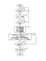
- FIG. 4 is a flowchart showing an example of the starter motor start control in the start-up power generation control device 100 shown in FIG.
- an ignition switch (not shown) is turned on by the user while the engine 2 is stopped, power is supplied from the battery 9 to the control unit 7 and the CPU 72 performs predetermined initial processing.
- the CPU 72 waits until the starter switch 8 is turned on ("N" is repeated in step S11).
- the CPU 72 executes stage determination processing (from “Y” in step S11 to step S12).
- step S12 the CPU 72 first turns off the MOSFETs (Q7) to (Q9) of the second power conversion unit 62, and electrically separates the winding part ACG1 and the winding part ACG2.
- the CPU 72 controls the MOSFETs (Q1) to (Q6) of the first power conversion unit 61 to be on or off, so that the motor does not move according to a plurality of predetermined energization patterns determined in advance in the winding unit ACG1.
- the short pulses are sequentially energized.
- the rotor position determination circuit 75 determines the rotor stage by comparing the voltage induced in the winding part ACG2 between a plurality of energization patterns.
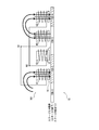
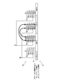
- FIG. 5 is a schematic diagram illustrating a configuration example of the field portion 15, the armature portion 161 including the armature core 16, the winding portion ACG 1, and the winding portion ACG 2 in the starter generator 1.
- the windings U1, V1, and W1 constituting the winding portion ACG1 are the windings U1-1 to U1-3, the windings V1-1 to V1-3, and the windings W1-1 to W1-3, respectively.
- the windings U2, V2 and W2 constituting the winding part ACG2 are composed of windings U2-1 to U2-3, windings V2-1 to V2-3 and windings W2-1 to W2-3, respectively. ing.
- the number of poles of the field portion 15 is 12.
- the field unit 15 includes N-pole permanent magnets 15N-1, 3, 5, 7, 9 and 11 in which respective poles are alternately arranged, and S-pole permanent magnets 15S-2, 4, 6, 8, 10 and 12 (hereinafter, a permanent magnet is also simply referred to as a magnet).
- the number of slots of the armature core 16 is 18, and each slot has one of the windings U1-1 to U1-3, the windings V1-1 to V1-3, or the windings W1-1 to W1-3.
- the windings U2-1 to U2-3, the windings V2-1 to V2-3, or one of the windings W2-1 to W2-3 are alternately wound.
- FIG. 6 schematically shows the rotor positions of the six stages in the combination of the field part 15 and the armature part 161 shown in FIG. Each stage differs in electrical angle every 60 °.
- FIG. 7 shows the correspondence between energization patterns, induced voltages, and stage determination results.
- MOSFETs (Q7) to (Q9) are all off.
- the energization pattern “V1 ⁇ U1” is a pattern in which the MOSFET (Q2) and the MOSFET (Q4) are turned on to energize the winding U1 from the winding V1.
- the energization pattern “V1 ⁇ W1” is a pattern in which the MOSFET (Q2) and the MOSFET (Q6) are turned on to energize the winding W1 from the winding V1.
- the energization pattern “W1 ⁇ U1” is a pattern in which the MOSFET (Q3) and the MOSFET (Q4) are turned on to energize the winding U1 from the winding W1.
- the induced voltage “W2-N2” is the voltage of the winding W2 with respect to the neutral point N2.
- the induced voltage “U2-N2” is a voltage of the winding U2 with respect to the neutral point N2.
- the induced voltage “V2-N2” is the voltage of the winding V2 with respect to the neutral point N2.
- the rotor position determination circuit 75 applies the voltage “W2-N2” during the energization pattern “U1 ⁇ V1” and the energization pattern “V1 ⁇ U1”, and the energization pattern “V1 ⁇ W1”.
- the voltage “U2-N2” is measured when W1 ⁇ V1 ”, and the voltage“ V2-N2 ”is measured sequentially when the energization pattern“ W1 ⁇ U1 ”and energization pattern“ U1 ⁇ W1 ”. Then, the rotor position determination circuit 75 determines the stage based on the measurement result of the induced voltage in each energization pattern.
- the rotor position determination circuit 75 applies the pulse current to the winding portion ACG1 of the winding portion ACG1 and the winding portion ACG2, and thereby the magnitude and polarity of the voltage induced in the other winding portion ACG2. And determine the stage. At this time, the rotor position determination circuit 75 can determine the stage based on, for example, a comparison result between the induced voltage and predetermined positive and negative reference voltages + Vref and ⁇ Vref. In the example of FIG.
- stage 7 for example, in order to determine stage 1, if “U1 ⁇ V1” is energized and “W2 ⁇ N2> + Vref” is energized, “U1 ⁇ W1” is energized, and if “V2 ⁇ N2> + Vref”. Stage 4 can be confirmed.
- the induced voltage shown in FIG. 7 schematically shows the magnitude when the rotor position is near the center of each stage.
- the induced voltage may not exceed the positive or negative reference voltage + Vref or ⁇ Vref. That is, the induced voltage in the vicinity of the boundary between two different stages shown as “stage boundary” in FIG. 7 is suddenly decreased before and after the boundary because the polarity is reversed, and cannot exceed the reference voltage + Vref or ⁇ Vref. .
- the induced voltage in the vicinity of the boundary between the stage 3 and the stage 4 there is a case where no voltage is induced in “V2 ⁇ N2” by energizing “U1 ⁇ W1”.
- the rotor position determination circuit 75 detects that the rotor is positioned near the stage boundary by measuring the induced voltage, the magnitudes and pulse widths of different sets of induced voltages are compared. By doing so, it was decided whether it was the boundary center or which stage.
- FIG. 8 schematically shows the rotor position from the stage 3 to the stage 4 in the combination of the field part 15 and the armature part 161 shown in FIG.
- FIG. 8 shows the rotor position at the beginning of stage 3, the rotor position at the boundary between stage 3 and stage 4 (that is, the end of stage 3 or the beginning of stage 4), and the rotor position at the end of stage 4. ing.
- the induced voltage generated between the winding V2 and the neutral point N2 at the rotor position at the boundary between the stage 3 and the stage 4 shown in FIG. 8 will be described in detail with reference to FIG. 9 and FIG. 10 to FIG. 13 and FIG. 15 to FIG. 18 which will be described later, the magnetic lines of force before the coil portion ACG1 is energized with a pulse are indicated by white arrows, and the magnetic lines of force upon energization are indicated by black arrows. . Further, in each figure, in order to schematically represent the difference in the number of magnetic lines of force, one magnetic line is indicated by a thick arrow, and 0.5 magnetic lines are indicated by a thin arrow. As shown in FIG.
- the armature core 16 around which the winding V2-1 is wound (hereinafter referred to as the armature core around which the winding V2-1 is wound).
- the 16-tooth portion is called the magnetic pole of the winding V2-1 (the same applies to the other windings)) because it is located at the center of the S-pole magnet 15S-2 and the N-pole magnet 15N-3. There are no lines of magnetic force that penetrate the magnetic poles.
- the magnetic pole of the winding U1-1 has a magnetic pole opposite to the magnet 15-S2, and the magnetic pole of the winding W1-1 has a magnetic pole opposite to the magnet 15-N3. Magnetized in the south pole. Since the magnetic field lines from the winding U1-1 and the winding W1-1 are opposite to each other in the magnetic pole of the winding V2-1, the magnetic pole of the winding V2-1 is fed from the winding U1-1 or the winding W1-1. Magnetic field lines do not penetrate.
- the magnetic flux before energization has a distribution indicated by white arrows.
- V1 ⁇ N1 ⁇ W1 When “V1 ⁇ N1 ⁇ W1” is energized, the magnetic pole of the winding W1-1 is magnetized to the S pole, and the lines of magnetic force increase by two compared to before energization.
- the line of magnetic force penetrating the magnetic pole of the winding U2-1 increases by one due to the line of magnetic force from the winding W1-1. Therefore, an induced voltage indicated by an arrow shaded in the direction from the neutral point N2 toward the winding U2-1 is applied. Arise.
- the magnetic flux before energization has a distribution indicated by white arrows.
- V1 ⁇ N1 ⁇ W1 When “V1 ⁇ N1 ⁇ W1” is energized, the magnetic pole of the winding W1-1 is magnetized to the S pole, and the magnetic field lines increase by one.
- the line of magnetic force penetrating the magnetic pole of the winding U2-1 increases by one due to the line of magnetic force from the winding W1-1. Therefore, an induced voltage indicated by an arrow shaded in the direction from the neutral point N2 toward the winding U2-1 is applied. Arise.
- the magnetic flux distribution is indicated by a white arrow.
- the magnetic pole of the winding U2-1 approaches the center of the magnet 15-S4, so that the magnetic field lines increase by 0.5.
- the magnetic pole of the winding V1-1 is magnetized to the S pole by the magnet 15-N5.
- V 1 ⁇ N 1 ⁇ W 1 is applied, the magnetic pole of the winding W 1-1 is magnetized to the S pole and the line of magnetic force increases by one.
- the magnetic pole of the winding V1-1 Since the magnetic pole of the winding V1-1 is magnetized to the N pole, it is demagnetized and the lines of magnetic force are reduced. Accordingly, all the lines of magnetic force generated in the winding W1-1 pass through the magnetic poles of the winding U2-1. For this reason, the change in the number of lines of magnetic force before and after energization of the magnetic pole of the winding U2-1 is 0.5, and the voltage induced in the winding U2 is smaller than that at the center of the boundary.
- the magnetic flux before energization has a distribution indicated by white arrows.
- the magnetic pole of the winding U2-1 approaches the center of the magnet 15S-4, so that the lines of magnetic force increase, and the magnetic pole of the winding V1-1 is magnetized to the S pole by the magnet 15N-5.
- V 1 ⁇ N 1 ⁇ W 1 is applied, the magnetic pole of the winding W 1-1 is magnetized to the S pole and the line of magnetic force increases by one.
- the magnetic pole of the winding V1-1 Since the magnetic pole of the winding V1-1 is magnetized to the N pole, it is demagnetized and the lines of magnetic force are reduced. Accordingly, all the lines of magnetic force generated in the winding W1-1 pass through the magnetic poles of the winding U2-1. For this reason, since the number of lines of magnetic force hardly changes before and after energization of the magnetic pole of the winding U2-1, no induced voltage is generated in the winding U2.
- FIG. 14 schematically shows the waveform of the induced voltage generated between the winding U2 and the neutral point N2, with the horizontal axis representing time and the vertical axis representing voltage.
- 14A shows a case where the rotor position is on the stage 3
- FIG. 14B shows a case where the rotor position is at the center of the boundary between the stage 3 and the stage 4
- FIG. 14C shows a case where the rotor position is on the stage 3 and It is a waveform of an induced voltage when moving away from the boundary of the stage 4 in the direction of the stage 4.
- the magnitude of the induced voltage for example, peak value, average value of absolute values, effective value, etc.
- the pulse width decrease.
- the magnetic flux before energization has a distribution indicated by white arrows.
- the magnetic pole of the winding U1-2 is magnetized to the N pole and the magnetic field lines increase by two.
- the line of magnetic force penetrating the magnetic pole of the winding W2-1 increases by one due to the line of magnetic force from the winding U1-2, so that an induced voltage indicated by an arrow shaded in the direction from the winding W2 toward the neutral point N2 is generated.
- the magnetic flux before energization has a distribution indicated by white arrows.
- the magnetic pole of the winding U1-2 is magnetized to the N pole, and the magnetic field lines increase by one.
- the line of magnetic force penetrating the magnetic pole of the winding W2-1 increases by one due to the line of magnetic force from the winding U1-2, so that an induced voltage indicated by an arrow shaded in the direction from the winding W2 toward the neutral point N2 is generated.
- the magnetic flux before energization has a distribution indicated by white arrows.
- the magnetic pole of the winding W2-1 approaches the center of the magnet 15N-5, so that the magnetic field lines increase by 0.5, and the magnetic pole of the winding V1-1 is magnetized to the N pole by the magnet 15S-4. Is done.
- the magnetic pole of U1-2 is magnetized to the N pole and the magnetic field lines increase by one.
- the magnetic pole of the winding V1-1 Since the magnetic pole of the winding V1-1 is magnetized to the S pole, it is demagnetized and the lines of magnetic force are reduced. Therefore, all the lines of magnetic force generated in the winding U1-2 pass through the magnetic pole of the winding W2-1. For this reason, the change in the number of lines of magnetic force before and after energization of the magnetic pole of the winding W2-1 is 0.5, and the voltage induced in the winding W2 is smaller than that at the center of the boundary.
- the magnetic flux before energization has a distribution indicated by white arrows.
- the magnetic pole of the winding W2-1 approaches the center of the magnet 15N-5, so that the lines of magnetic force increase, and the magnetic pole of the winding V1-1 is magnetized to the N pole by the magnet 15S-4.
- the magnetic pole of the winding U1-2 is magnetized to the N pole, and the magnetic field lines increase by one.
- the magnetic pole of the winding V1-1 Since the magnetic pole of the winding V1-1 is magnetized to the S pole, it is demagnetized and the lines of magnetic force are reduced. Therefore, all the lines of magnetic force generated in the winding U1 pass through the magnetic pole of the winding W2-1. For this reason, there is almost no change in the number of lines of magnetic force before and after energization of the magnetic pole of the winding W2-1, so that no induced voltage is generated in the winding W2.
- FIG. 19 schematically shows the waveform of the induced voltage generated between the winding W2 and the neutral point N2, with the horizontal axis representing time and the vertical axis representing voltage.
- 19A shows a case where the rotor position is on the stage 4
- FIG. 19B shows a case where the rotor position is at the center of the boundary between the stage 3 and the stage 4
- FIG. 19C shows a case where the rotor position is on the stage 3 and It is a waveform of the induced voltage when moving away from the boundary of the stage 4 in the direction of the stage 3.
- the magnitude of the induced voltage for example, peak value, average value of absolute values, effective value, etc.
- pulse width decrease.
- the rotor position determination circuit 75 first energizes from U1 to V1 (FIG. 20: step S101 of stage determination 1). Next, the rotor position determination circuit 75 compares the voltage W2-N2 measured during energization from U1 to V1 with the positive reference voltage + Vref (step S102). When voltage W2-N2 is not greater than + Vref (step S102: N), rotor position determination circuit 75 compares voltage W2-N2 with negative reference voltage -Vref (step S103). When voltage W2-N2 is not smaller than ⁇ Vref (step S103: N), rotor position determination circuit 75 advances the process to stage determination 2 shown in FIG. 21 (step S104).
- step S103 when the voltage W2-N2 is smaller than -Vref (step S103: Y), the rotor position determination circuit 75 supplies power from W1 to U1 (step S105). Subsequently, the rotor position determination circuit 75 compares the voltage V2-N2 measured during energization from W1 to U1 with the positive reference voltage + Vref (step S106). When voltage V2-N2 is not greater than + Vref (step S106: N), rotor position determination circuit 75 determines that the positional relationship (rotor position) is stage 5 (step S111), and ends the process (step S110). ).
- step S106 determines the absolute value of the voltage W2-N2 measured during energization from U1 to V1 in step S101 and W1 in step S105. Is compared with the absolute value of the voltage V2-N2 measured during energization from U to U1 (step S107).
- step S107 the voltage W2 is determined in the determination process in step S107.
- the absolute value of -N2 is compared with the voltage V2-N2.
- step S107: Y When the absolute value of voltage W2-N2 is greater than or equal to the absolute value of voltage V2-N2 (step S107: Y), rotor position determination circuit 75 determines that the positional relationship is stage 5 (step S108), and performs processing. The process ends (step S110). On the other hand, when the absolute value of voltage W2-N2 is not equal to or greater than the absolute value of voltage V2-N2 (step S107: N), rotor position determination circuit 75 determines that the positional relationship is stage 6 (step S109) and performs processing. Is finished (step S110).
- step S102 if the voltage W2-N2 is greater than + Vref in step S102 (step S102: Y), the rotor position determination circuit 75 supplies power from V1 to W1 (step S112). Subsequently, the rotor position determination circuit 75 compares the voltage U2-N2 measured during energization from V1 to W1 with the negative reference voltage -Vref (step S113). When voltage V2-N2 is not smaller than -Vref (step S113: N), rotor position determination circuit 75 determines that the positional relationship is stage 4 (step S114), and ends the process (step S110).
- step S113 determines the absolute value of the voltage W2-N2 measured during energization from U1 to V1 in step S101, and in step S112.
- the absolute value of voltage U2-N2 measured during energization from V1 to W1 is compared (step S115).
- the voltage U2 is determined in the determination process in step S115.
- the absolute value of -N2 is compared with the voltage W2-N2.
- step S115: Y When the absolute value of voltage W2-N2 is greater than or equal to the absolute value of voltage U2-N2 (step S115: Y), rotor position determination circuit 75 determines that the positional relationship is stage 4 (step S116), and performs processing. The process ends (step S110). On the other hand, when the absolute value of voltage W2-N2 is not equal to or greater than the absolute value of voltage U2-N2 (step S116: N), rotor position determination circuit 75 determines that the positional relationship is stage 3 (step S117) and performs processing. Is finished (step S110).
- stage discrimination 1 the outline of the process of stage discrimination 1 shown in FIG. 20 is summarized as follows. That is, if a voltage is induced in “W2 ⁇ N2” by energization of “U1 ⁇ V1”, it branches from its polarity and magnitude. If the voltage induced in “W2-N2” is “+” polarity, “V1 ⁇ W1” is further applied. If the voltage of “U2-N2” is smaller than ⁇ Vref, the stage 4 is determined. On the other hand, if the voltage of “U2-N2” is not smaller than ⁇ Vref, the absolute value is compared with “W2-N2”. If the voltage of “U2-N2” is not large, stage 4 is determined. 3 is confirmed.
- stage 5 is determined.
- the absolute value is compared with “W2 ⁇ N2”. If the voltage “V2 ⁇ N2” is large, the stage 6 is determined. To do. If no voltage is induced in “W2-N2” by energizing “U1 ⁇ V1”, stage determination 2 is executed.
- the rotor position determination circuit 75 first energizes from U1 to W1 (step S201). Next, the rotor position determination circuit 75 compares the voltage V2-N2 measured during energization from U1 to V1 with the positive reference voltage + Vref (step S202). When the voltage V2-N2 is not greater than + Vref (step S202: N), the rotor position determination circuit 75 compares the voltage V2-N2 with the negative reference voltage -Vref (step S203). If voltage V2-N2 is not smaller than -Vref (step S203: N), rotor position determination circuit 75 advances the process to stage determination 3 shown in FIG. 22 (step S204). On the other hand, if the voltage V2-N2 is smaller than -Vref (step S203: Y), the rotor position determination circuit 75 determines that the positional relationship is the stage 3 (step S205) and ends the process (step S206).
- step S202 when the voltage V2-N2 is higher than + Vref in step S202 (step S202: Y), the rotor position determination circuit 75 supplies power from W1 to V1 (step S207). Subsequently, the rotor position determination circuit 75 determines the absolute value of the voltage V2-N2 measured when energizing from U1 to W1 in step S201 and the absolute value of the voltage U2-N2 measured when energizing from W1 to V1 in step S207. Are compared (step S208). However, in the flow shown in FIG. 21, since the sign of the voltage W2-N2 compared in step S208 is determined to be positive in the determination in step S202, the voltage U2 is determined in the determination process in step S208.
- the absolute value of -N2 is compared with the voltage V2-N2.
- rotor position determination circuit 75 determines that the positional relationship is stage 5 (step S210), and performs processing. The process ends (step S206).
- rotor position determination circuit 75 determines that the positional relationship is stage 4 (step S209) and performs processing. Is finished (step S206).
- stage determination 2 the summary of the process of stage discrimination 2 shown in FIG. 21 is summarized as follows.
- the premise of the process of stage determination 2 is as follows. That is, if no induced voltage is generated in “W2-N2” by energization of “U1 ⁇ V1”, the following is found. That is, the rotor position may be on the boundary between the stage 4 and the stage 5. Further, the rotor position is not on the boundary between the stage 3 and the stage 4 or on the boundary between the stage 5 and the stage 6.
- the rotor position is on stage 4 to stage 5 if the induced voltage is a positive polarity voltage, and on the stage 3 if the induced voltage is a negative polarity voltage. If no induced voltage is generated, the rotor position is not on the boundary between the stage 4 and the stage 5. Alternatively, the rotor position is not on the boundary between the stage 2 and the stage 3. Alternatively, the rotor position is narrowed down to any one of the stages 1, 2, and 6, the boundary between the stage 1 and the stage 2, and the boundary between the stage 6 and the stage 1 as the remaining possibility. This possibility is determined by the process of stage determination 3.
- the rotor position determination circuit 75 first energizes from V1 to U1 (step 301). Next, the rotor position determination circuit 75 compares the voltage W2-N2 measured during energization from V1 to U1 with the positive reference voltage + Vref (step S302). When voltage W2-N2 is greater than + Vref (step S302: Y), rotor position determination circuit 75 determines that the positional relationship is stage 2 (step S303), and ends the process (step S304).
- step S302 when the voltage W2-N2 is not greater than + Vref (step S302: N), the rotor position determination circuit 75 compares the voltage W2-N2 with the negative reference voltage -Vref (step S305). When voltage W2-N2 is not smaller than -Vref (step S305: N), rotor position determination circuit 75 energizes W1 to V1 (step S306). Subsequently, the rotor position determination circuit 75 determines the absolute value of the voltage W2-N2 measured when energizing from V1 to U1 in step S301 and the absolute value of the voltage U2-N2 measured when energizing from W1 to V1 in step S306. Are compared (step S307).
- the determination processing in step S301 is processing for determining whether the positional relationship is the stage 1 or the stage 6 when the positional relationship is near the boundary between the stage 1 and the stage 6. Further, in the vicinity of the boundary between stage 1 and stage 6, as shown in FIG. 7, voltage U2-N2 at the time of energization from W1 to V1 is positive, and voltage W2-N2 at the time of energization from V1 to U1. Is negative. Therefore, in the determination process in step S301, the absolute value of the voltage W2-N2 is compared with the voltage U2-N2.
- step S307: N When the absolute value of voltage U2-N2 is not equal to or greater than the absolute value of voltage W2-N2 (step S307: N), rotor position determination circuit 75 determines that the positional relationship is stage 1 (step S308) and ends the process. (Step S304). On the other hand, when the absolute value of voltage W2-N2 is equal to or greater than the absolute value of voltage V2-N2 (step S307: Y), rotor position determination circuit 75 determines that the positional relationship is stage 6 (step S309). The process ends (step S304).
- step S305: Y when the voltage W2-N2 is smaller than ⁇ Vref in step S305 (step S305: Y), the rotor position determination circuit 75 supplies power from W1 to U1 (step S310). Subsequently, the rotor position determination circuit 75 compares the voltage V2-N2 measured during energization from W1 to U1 with the positive reference voltage + Vref (step S311). When voltage V2-N2 is greater than + Vref (step S311Y), rotor position determination circuit 75 determines that the positional relationship is stage 6 (step S312), and ends the process (step S304). On the other hand, if voltage V2-N2 is not greater than + Vref (step S311: N), rotor position determination circuit 75 determines that the positional relationship is stage 1 (step S313), and ends the process (step S304).
- stage discrimination 3 the outline of the process of stage discrimination 3 shown in FIG. 22 is summarized as follows.
- the following can be found. That is, if an induced voltage is generated, the rotor position is on stage 2 if the induced voltage is + polarity, and is on stage 1 or the boundary between stage 6 and stage 1 if the induced voltage is -polarity.
- the rotor position is not on the boundary between stage 6 and stage 1 but on the boundary between stage 1 and stage 2 or on stage 6 if no induced voltage is generated.
- the rotor position determination circuit 75 executes the stage determination process in step S12 of FIG.
- the CPU 72 determines in the rotor position determination circuit 75 whether or not the stage determination processing has been normally completed (step S13). On the other hand, when the stage determination process has not ended normally (in the case of “N” in step S13), the CPU 72 executes the determination process in step S12 again (from “Y” in step S11 to step S12). On the other hand, when the stage determination process has been completed normally (in the case of “Y” in step S13), the CPU 72 uses the first power conversion unit 61 and the first power generation pattern with the energization pattern corresponding to the stage determined by the rotor position determination circuit 75. (2) The energization control of the MOSFETs (Q1) to (Q9) of the power converter 62 is started (step S14). At that time, for example, the CPU 72 sets the energization angle of the first power conversion unit 61 to 180 °, and sets the energization angle of the second power conversion unit 62 to 120 ° or more and less than 180 °.
- the zero cross detection circuit 74 After the starter / generator 1 starts rotating, the zero cross detection circuit 74 generates a stage signal based on the zero cross point of the output voltage of the winding part ACG2 and outputs it to the CPU 72 (step S15). Then, the CPU 72 performs energization control on the first power conversion unit and the second power conversion unit in a pattern corresponding to the stage detected by the zero-cross detection circuit 74 (step S15).
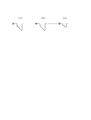
- FIG. 23 is a waveform diagram schematically showing the output voltage waveform of the winding U2 of the winding portion ACG2 and the detection waveform of the zero-cross point of the output voltage of the winding U2 by the rotor position determination circuit 75.
- the conduction angle of the second power converter 62 in step S14 and step S15 is set to 120 °.
- the detected waveform of the zero cross point rises or falls in the same direction as the change of the output voltage at the zero cross point of the output voltage.
- the zero-cross detection circuit 74 generates a detection waveform of each phase from the output voltage waveforms of the windings U2, V2, and W2, generates a stage signal indicating the rotor position based on the detection waveform of each phase, and outputs it to the CPU 72. To do.
- the CPU 72 determines whether or not the engine has been started (step S16). If the engine has not been started (in the case of “N” in step S16), the CPU 72 returns to step S15 and continues the energization control with a pattern corresponding to the stage detected by the zero cross detection circuit 74 (step S15). ). If the engine has been started ("Y" in step S16), the CPU 72 stops energizing the motor and ends the starter motor start control (step S17).
- the starter motor control first, all the MOSFETs of the second power converter 62 are turned off. Then, the first power converter 61 is used to sequentially energize the winding ACG1 with short pulses that do not cause the motor to move according to a predetermined energization pattern. And the rotor position determination circuit 75 determines the rotor stage at the time of a stop with the voltage information induced at the both ends of winding of other winding part ACG2. Next, the CPU 72 converts the energization pattern corresponding to the rotor stage specified by the rotor position determination circuit 75 to the first power conversion unit 61 and the second power connected to the phases of the winding part ACG1 and the winding part ACG2.
- the first power converter 61 starts energization at any angle of 180 ° and the second power converter 62 at 120 ° or more and less than 180 °.
- the CPU 72 completes starting of the engine in the winding portions ACG1 and ACG2 based on the rotor position information derived from the zero cross point of the winding portion ACG2 detected by the zero cross detection circuit 74. Energize.
- the winding portion ACG2 can be used for detecting the zero cross point, and both the winding portion ACG1 and the winding portion ACG2 are used as the starting winding. Is possible.
- both the winding portion ACG1 and the winding portion ACG2 are used.
- the starting torque can be reduced as much as possible from the 180 ° energization mode.
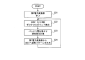
- FIG. 24 is a flowchart showing an example of power generation control in starter power generation control device 100 shown in FIG. After the start of the engine 2 is completed, the CPU 72 turns off the MOSFETs (Q7) to (Q9) of the second power conversion unit 62 (step S21).
- the CPU 72 inputs the stage signal generated by the zero cross detection circuit 74 based on the zero cross point of the output voltage of the winding part ACG2 (step S22).
- FIG. 25 is a waveform diagram schematically showing the output voltage waveform of the winding U2 of the winding portion ACG2 and the detection waveform of the zero-cross point of the output voltage of the winding U2 by the rotor position determination circuit 75.
- the second power conversion unit 62 is controlled to be in an off state.
- the detected waveform of the zero cross point rises or falls in the same direction as the change of the output voltage at the zero cross point of the output voltage.
- the zero-cross detection circuit 74 generates a detection waveform for each phase from the output voltage waveforms of the windings U2, V2, and W2 as shown in FIG. 25, and represents the rotor position in stages based on the detection waveform for each phase.
- a signal is generated and output to the CPU 72.
- the CPU 72 calculates the energization angle of the first power control unit 61 based on the voltage value of the battery 9 (step S23).
- the CPU 72 outputs a retardation pattern based on the amount of retardation calculated in step S23 from the first power converter 61 to the winding part ACG1 (step S24). And CPU72 returns to step S22 and performs the process mentioned above again.
- the first power converter 61 converts the AC voltage of the winding part ACG1 by deriving the rotor position from the zero cross point of the no-load voltage generated at both ends of the winding of the winding part ACG2 by the zero cross detection circuit 74. The timing required for phase control is generated. Thereby, according to this embodiment, the optimal electric power can be supplied to the battery 9 or an electrical load (not shown).
- the rotor can be positioned by a simple method without using an expensive sensor and without using a subcoil.
- an armature part in which a winding part ACG1 and a winding part ACG2 that are three-phase windings (multi-phase windings) are arranged in parallel, and a field part made of a permanent magnet are provided.
- a starter generator 1 ACG starter motor
- a first power conversion unit 61 that is connected to the winding part ACG1 or the winding part ACG1 and the winding part ACG2, and performs power conversion between AC and DC, and a winding
- the AC terminals 611, 612, and 613 of the first power conversion unit 61 connected to the ends of the unit ACG1 and the ends of the winding unit ACG2, and the AC terminals 611 and 612.
- And 613 are provided with a plurality of MOSFETs (switch elements) (Q7) to (Q9) for connecting and separating each end of the winding part ACG2. According to this configuration, it is possible to easily improve the control characteristics of the starter generator 1, such as reduction of power loss.
- the balance between power generation and electric load is optimized by dividing the winding part into, for example, two parts and using both. can do.
- this configuration it is possible to reduce surplus power generated due to imbalance with the electrical load when a motor whose winding specifications are designed to satisfy the torque characteristics of the starter motor is used as a generator. That is, the circulating current in the winding part can be reduced, and the heat generation (power loss) of the winding and the power device element can be reduced. Therefore, it is possible to easily reduce surplus power during power generation without impairing the motor torque. As a result, the fuel efficiency of the engine 2 can be improved and the friction can be reduced.
- the heat generation of the armature winding and power device can be reduced by reducing the circulating current during power generation control.
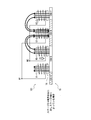
- FIG. 26 is a block diagram illustrating a configuration example of the starting power generation control device 100b according to the second embodiment of the present invention.
- the configuration and operation of the detection / determination circuit unit 73 are the same as those in the above embodiment.
- the start power generation control device 100a of the second embodiment is different from the start power generation control device 100 shown in FIG. 3 in the following points. That is, the second power conversion unit 62a newly includes MOSFETs (Q10) to (Q12).
- the drain of the MOSFET (Q10) is connected to the drain of the MOSFET (Q7).
- the drain of the MOSFET (Q11) is connected to the drain of the MOSFET (Q8).
- the drain of the MOSFET (Q12) is connected to the drain of the MOSFET (Q9).
- the sources of the MOSFET (Q10), MOSFET (Q11) and MOSFET (Q12) are grounded.
- the MOSFET gate drive circuit 71a is provided with newly provided circuits for the MOSFETs (Q10) to (Q12) with respect to the MOSFET gate drive circuit 71 shown in FIG.
- the CPU 72a is added with programs for newly provided MOSFETs (Q10) to (Q12) with respect to the CPU 72 shown in FIG.
- the starting power generation control device 100a of the second embodiment by providing two sets of negative-side MOSFETs for the winding part ACG1 and the winding part ACG2, the current flowing through the negative-side MOSFET is limited, Heat generation of each MOSFET can be reduced.
- FIG. 27 is a block diagram illustrating a configuration example of the starting power generation control device 100b according to the third embodiment of the present invention.
- the same components as those shown in FIG. 3 or FIG. the same basic functions as those shown in FIG. 3 are given the same reference numerals with the letter “b” added to the end.
- the configuration and operation of the detection / determination circuit unit 73 are the same as those in the above embodiments.
- the start power generation control device 100b of the third embodiment is different from the start power generation control device 100 shown in FIG. 3 in the following points. That is, the first power conversion unit 61b newly includes a MOSFET (Q13) (first switch element) with respect to the first power conversion unit 61 illustrated in FIG. This MOSFET (Q 13) is interposed between the positive DC terminal 614 and the positive DC terminal 616 connected to the battery 9. The drain of the MOSFET (Q13) is connected to the positive DC terminal 614, and the source of the MOSFET (Q13) is connected to the positive DC terminal 616.
- MOSFET first switch element
- the second power converter 62b includes six MOSFETs (Q17) to (Q19) and (Q10) to (Q12), and constitutes a three-phase bridge orthogonal transformer circuit.
- the orthogonal transform unit 62b includes a positive DC terminal 624 on the positive side of the DC input / output line of the three-phase bridge orthogonal transform circuit composed of MOSFETs (Q17) to (Q19) and (Q10) to (Q12).
- the negative side DC terminal 625 is provided on the negative side.
- the three-phase bridge quadrature transformation circuit composed of the MOSFETs (Q17) to (Q19) and (Q10) to (Q12) includes the winding U2, winding V2, and winding W2 of the winding portion ACG2 as AC terminals 621, Connected to 622 and 623 to convert power in both directions between DC and AC.
- the second power converter 62b includes a MOSFET (Q14) (second switch element) between the positive DC terminal 624 and the positive DC terminal 626 connected to the battery 9.
- the drain of the MOSFET (Q14) is connected to the positive DC terminal 624, and the source of the MOSFET (Q14) is connected to the positive DC terminal 626.
- MOSFETs (Q7) to (Q9) are omitted as compared to the second power conversion unit 62 shown in FIG.
- the MOSFET gate drive circuit 71b is for the MOSFETs (Q10) to (Q14) and (Q17) to (Q19) newly provided with respect to the MOSFET gate drive circuit 71 shown in FIG. A circuit has been added. Further, the CPU 72b has programs changed for the newly provided MOSFETs (Q10) to (Q14) and (Q17) to (Q19) with respect to the CPU 72 shown in FIG.
- the starting power generation control device 100b of the third embodiment by turning on or off the MOSFET (Q13) and the MOSFET (Q14), at the time of power generation control, the generated power is output only from the winding portion ACG1 or the winding portion. Control can be performed such that the generated power is output only from the ACG 2 or the generated power is output from both the winding part ACG1 and the winding part ACG2.
- power generation and electric load can be performed by dividing the winding part into two cases, for example, when using both and when using one of them. And balance can be optimized. According to this configuration, it is possible to reduce surplus power generated due to imbalance with the electrical load when a motor whose winding specifications are designed to satisfy the torque characteristics of the starter motor is used as a generator. That is, the circulating current in the winding part can be reduced, and the heat generation (power loss) of the winding and the power device element can be reduced. Therefore, it is possible to easily reduce surplus power during power generation without impairing the motor torque. As a result, the fuel efficiency of the engine 2 can be improved and the friction can be reduced.
- the generated torque in the motor control and the power generation output in the power generation control for example, when using the winding part ACG1
- the winding portion ACG2 can be selected in three stages, and the winding portion ACG1 and the winding portion ACG2 are used.
- the starter generator 1 in which the winding part ACG1 and the winding part ACG2 are arranged in parallel is used for starting the engine 2 and used as a generator.
- the winding portion ACG2 is used as a detection winding for detecting the position of the rotor, so that the position of the rotor can be detected with high accuracy without providing a hall sensor. For this reason, since it is not necessary to arrange an expensive hall sensor corresponding to high mounting accuracy, it is possible to provide a starter generator that is inexpensive and capable of detecting the rotor with high accuracy.
- the winding portion ACG2 (second multiphase winding) is applied.
- the stop position of the rotor can be determined by detecting the value of the phase voltage generated in the winding. According to this, current detection can be made unnecessary.
- two different phase voltages detected when two different energization patterns are applied to each other since the stage is determined based on the result of comparing the two, the stage can be determined with high accuracy even on the boundary.
- the rotor position determination circuit 75 compares the phase voltages of a plurality of different phases of the winding part ACG2 detected when line voltages are applied to the winding part ACG1 with different energization patterns.
- the magnitude of the phase voltage such as the absolute value of the high value, the absolute value of the average value of the phase voltage, and the effective value of the phase voltage, can be compared.
- the rotor position determination circuit 75 compares the length of the pulse width in addition to the size, or determines the length of the pulse width instead of the size. You may make it compare.
- Start-up power generation control device 1 Start-up generator ACG1, ACG2 Winding unit 61, 61b First power conversion unit 62, 62a Second power conversion unit 7, 7a, 7b Control unit U1, V1, W1, U2, V2, W2 Winding 72 CPU 73 Detection / Determination Circuit Unit 74 Zero Cross Detection Circuit 75 Rotor Position Determination Circuits Q1-Q14, Q17-Q19 MOSFET
Landscapes
- Engineering & Computer Science (AREA)
- Power Engineering (AREA)
- Control Of Motors That Do Not Use Commutators (AREA)
Abstract
本発明の一実施形態に係る始動発電装置は、永久磁石からなる界磁部と、第1多相巻線および第2多相巻線が並列に配設された電機子部とを有する始動発電機と、バッテリに接続される第1正側直流端子と、前記第1多相巻線に接続された複数の第1交流端子とを有し、直流および交流間で双方向に電力を変換する第1電力変換部と、前記第2多相巻線に接続された複数の第2交流端子を有し、前記第2交流端子を介して入出力する電流を制御する第2電力変換部と、前記第2多相巻線の出力電圧に基づき前記界磁部と前記電機子部との位置関係を検知し、検知した前記位置関係に応じて前記第1電力変換部と前記第2電力変換部とを制御する制御部とを備え、前記制御部が、前記第2交流端子を介して入出力する電流をオフした状態で、前記第1多相巻線における巻線の組および電圧印加の向きで決まる複数の通電パターンを順次選択して所定の線間電圧を印加したときに検出された前記第2多相巻線の相電圧の値と、異なる前記通電パターンで前記線間電圧を印加したときに検出された前記第2多相巻線の異なる複数の相の前記相電圧の比較結果とに基づき、前記始動発電機の停止時における前記位置関係を検知する。
Description
本発明は、始動発電装置および始動発電方法に関する。
従来から、車両、特に小型二輪車などにおいては、エンジン始動時にスタータモータとして働くと共にエンジン始動後は発電機として働くACG(ACジェネレータ)スタータモータでは、三相DCブラシレスモータが用いられている(特許文献1)。この三相DCブラシレスモータのエンジン始動時および発電時におけるロータの位置検出では、三相巻線の各相の巻線の各々に対応してホールセンサを設け、このホールセンサを用いてロータの位置検出を行っていた。
一方、ホールセンサを使用せずにロータの位置を検知する技術が開発されてきた(特許文献2)。特許文献2に記載されている制御装置では、ブラシレスモータが停止している場合、3相巻線のうちの2巻線に複数パターンの直流電圧を短時間印加して、ロータ位置に応じて変化する電流の立ち上がり特性を計測することでロータの停止位置を検知していた。
しかしながら、特許文献2に記載されている制御装置には、巻線に流れる電流を検出するための回路が必要である。電流検出回路は、一般に電圧検出回路に比べ、構成が複雑であったり、損失が大きくなってしまったりするという傾向がある。そのため、特許文献2に記載されている制御装置には、小型化が難しかったり、低価格化が難しかったりするという課題があった。
本発明は、上記の課題を解決することができる始動発電装置および始動発電方法を提供することを目的とする。
上記の課題を解決するため、本発明の始動発電装置の一態様は、永久磁石からなる界磁部と、第1多相巻線および第2多相巻線が並列に配設された電機子部とを有する始動発電機と、バッテリに接続される第1正側直流端子と、前記第1多相巻線に接続された複数の第1交流端子とを有し、直流および交流間で双方向に電力を変換する第1電力変換部と、前記第2多相巻線に接続された複数の第2交流端子を有し、前記第2交流端子を介して入出力する電流を制御する第2電力変換部と、前記第2多相巻線の出力電圧に基づき前記界磁部と前記電機子部との位置関係を検知し、検知した前記位置関係に応じて前記第1電力変換部と前記第2電力変換部とを制御する制御部とを備え、前記制御部が、前記第2交流端子を介して入出力する電流をオフした状態で、前記第1多相巻線における巻線の組および電圧印加の向きで決まる複数の通電パターンを順次選択して所定の線間電圧を印加したときに検出された前記第2多相巻線の相電圧の値と、異なる前記通電パターンで前記線間電圧を印加したときに検出された前記第2多相巻線の異なる複数の相の前記相電圧の比較結果とに基づき、前記始動発電機の停止時における前記位置関係を検知する。
また、本発明の一態様は、上記の始動発電装置において、前記比較結果が、前記相電圧の絶対値の大きさを比較した結果である。
また、本発明の始動発電方法の一態様は、永久磁石からなる界磁部と、第1多相巻線および第2多相巻線が並列に配設された電機子部とを有する始動発電機と、バッテリに接続される第1正側直流端子と、前記第1多相巻線に接続された複数の第1交流端子とを有し、直流および交流間で双方向に電力を変換する第1電力変換部と、前記第2多相巻線に接続された複数の第2交流端子を有し、前記第2交流端子を介して入出力する電流を制御する第2電力変換部と、前記第2多相巻線の出力電圧に基づき前記界磁部と前記電機子部との位置関係を検知し、検知した前記位置関係に応じて前記第1電力変換部と前記第2電力変換部とを制御する制御部とを用い、前記制御部が、前記第2交流端子を介して入出力する電流をオフした状態で、前記第1多相巻線における巻線の組および電圧印加の向きで決まる複数の通電パターンを順次選択して所定の線間電圧を印加したときに検出された前記第2多相巻線の相電圧の値と、異なる前記通電パターンで前記線間電圧を印加したときに検出された前記第2多相巻線の異なる複数の相の前記相電圧の比較結果とに基づき、前記始動発電機の停止時における前記位置関係を検知する。
本発明によれば、第1多相巻線に複数の通電パターンで順次、線間電圧を印加したときに、第2多相巻線に発生する相電圧を検出することで、ロータの停止位置を判定することができる。これによれば電流検出を不要とすることができる。
以下、図面を参照して本発明の実施形態について説明する。なお、各図において同一または対応する構成には同一の参照符号を用いている。図1は、本発明の実施形態の始動発電制御装置100の構成例を示したブロック図である。図1に示した始動発電制御装置100は、始動発電機(ACGスタータモータ)1と、第1電力変換部61と、第2電力変換部62と、制御部7とを備える。始動発電機1は、クランクシャフト3に直結されていて、エンジン2の回転に同期して回転する。第1電力変換部61、第2電力変換部62および制御部7は、バッテリ9の正極が接続されるとともに、接地されている。バッテリ9は、負極が接地された2次電池である。また、スタータスイッチ8の一端がバッテリ9の正極に接続され、スタータスイッチ8の他端が制御部7に接続されている。スタータスイッチ8は、ユーザがエンジン2を始動する際に操作するスイッチである。また、制御部7には、エンジン水温計5の出力が接続されている。
始動発電機1は、第1電力変換部61および第2電力変換部62の制御によって、スタータモータとして動作したり、発電機として動作したりする。始動発電機1は、巻線部ACG1と巻線部ACG2と図2に示す界磁部15とを備える。巻線部ACG1はスター結線された3相巻線(多相巻線)を構成する巻線U1、V1およびW1を備える。巻線部ACG2はスター結線された3相巻線を構成する巻線U2、V2およびW2を備える。中性点N1は巻線部ACG1を構成するスター結線の中性点である。中性点N2は巻線部ACG2を構成するスター結線の中性点である。巻線U1、V1およびW1と、巻線U2、V2およびW2とは、図示してない同一の電機子鉄心に巻かれていて、電気的に絶縁されている1組の電機子巻線である。なお、巻線部ACG1と巻線部ACG2と図示してない電機子鉄心とは電機子部を構成する。なお、巻線部ACG1と巻線部ACG2とはスター結線に限らず、デルタ結線で構成されていてもよい。
図2は、始動発電機1の巻線部ACG1、巻線部ACG2および界磁部15の構成例を軸方向から見て模式的に示した図である。ただし、図2では、巻線U1と巻線U2とのみを示している。図2に示した構成例では、始動発電機1は、界磁部15を複数組のN極の永久磁石15NおよびS極の永久磁石15Sから構成したアウターロータ型のブラシレスモータである。なお、以下では界磁部15をロータとも称する。巻線U1は、図示してない電機子鉄心に対して120度おきに配設された3個の巻線U1-1、U1-2およびU1-3から構成されている。巻線U1の3個の巻線U1-1、U1-2およびU1-3は各一端を中性点N1に共通に接続し、各他端を巻線U1の入出力端子に共通に接続している。巻線U2は、図示してない電機子鉄心に対して120度おきかつ巻線U1-1、U1-2およびU1-3に対して60度ずれて配設された3個の巻線U2-1、U2-2およびU2-3から構成されている。巻線U2の3個の巻線U2-1、U2-2およびU2-3は各一端を中性点N2に共通に接続し、各他端を巻線U2の入出力端子に共通に接続している。なお、以下の説明において、回路の接続先として巻線U1または巻線U2という呼称を用いた場合、中性点N1または中性点N2とは逆の端子である巻線U1の入出力端子または巻線U2の入出力端子を指し示す。巻線V1、巻線W1、巻線V2、および巻線W2についても同様とする。また、巻線U1、巻線U2、巻線V1、巻線W1、巻線V2、巻線W2、中性点N1および中性点N2を、単に符号U1、U2、V1、W1、V2、W2、N1およびN2で表す場合もある。
なお、図1において、エンジン2は例えば小型二輪車に搭載された発動機である。クランクシャフト3は、エンジン2の構成部品であり、エンジン2が備える図示していないピストンの往復運動を回転運動に変換する軸である。エンジン水温計5は、エンジン2の冷却水の温度を検知するセンサである。
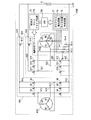
次に、図3を参照して、図1に示した第1電力変換部61、第2電力変換部62および制御部7の内部構成の一例について説明する。図3に示したように、第1電力変換部61は、6個のnチャネルMOSFET(金属酸化物半導体電界効果トランジスタ、以下、MOSFETと記す(スイッチ素子))(Q1)~(Q6)を備え、3相ブリッジ直交変換回路(多相ブリッジ回路)を構成する。第1電力変換部61は、直流入出力線の正側(ハイサイド)直流端子614(第1正側直流端子)をバッテリ9の正極に、負側(ローサイド)直流端子615をバッテリ9の負極に接続している。第1電力変換部61は、バッテリ9と巻線部ACG1との間、またはバッテリ9と巻線部ACG1および巻線部ACG2との間で、交流および直流間の双方向の電力変換を行う。また、第1電力変換部61の各交流端子(第1交流端子)611、612および613には、巻線部ACG1の各巻線U1、V1およびW1が接続されている。
第2電力変換部62は、3個の交流端子(第2交流端子)621、622および623と、3個のMOSFET(Q7)、(Q8)および(Q9)とを備える。交流端子621は、巻線部ACG2の巻線U2とMOSFET(Q7)のドレインとに接続されている。交流端子622は、巻線部ACG2の巻線V2とMOSFET(Q8)のドレインとに接続されている。交流端子623は、巻線部ACG2の巻線W2とMOSFET(Q9)のドレインとに接続されている。MOSFET(Q7)のソースは、第1電力変換部61の交流端子611に接続されている。MOSFET(Q8)のソースは、第1電力変換部61の交流端子612に接続されている。MOSFET(Q9)のソースは、第1電力変換部61の交流端子613に接続されている。第2電力変換部62は、MOSFET(Q7)、(Q8)および(Q9)をオンまたはオフすることで、交流端子621、622および623を介して入出力する電流を制御する。この場合、第2電力変換部62は、MOSFET(Q7)、(Q8)および(Q9)をオンまたはオフすることで、巻線部ACG2の各巻線U2、V2およびW2をそれぞれ第1電力変換部61の各交流端子611、612および613に接続したり、分離したりする。
また、この場合、3個のMOSFET(Q7)、(Q8)および(Q9)は、巻線部ACG1の各巻線U1、V1およびW1が接続されている第1電力変換部61の各交流端子611、612および613と、巻線部ACG2の各巻線U2、V2およびW2との間に介挿されている。そして、3個のMOSFET(Q7)、(Q8)および(Q9)は、巻線部ACG2の各巻線U2、V2およびW2を、オンすることで各交流端子611、612および613に対して接続したり、オフすることで各交流端子611、612および613から分離したりする。
また、各MOSFET(Q7)、(Q8)および(Q9)は、ドレイン・ソース間に寄生ダイオードD7、D8およびD9が形成されている(なお、他のMOSFETについては寄生ダイオードは不図示)。寄生ダイオードD7、D8およびD9の向きは、各交流端子611、612および613に対して同一であり、この場合、アノードが各交流端子611、612および613に接続されている。また、カソードは、巻線部ACG2の各巻線U2、V2およびW2に接続されている。このように寄生ダイオードD7、D8およびD9の向きをそろえることで、各MOSFET(Q7)、(Q8)および(Q9)をオフした場合に、モータ動作における第1電力変換部61を介したバッテリ9から巻線部ACG2への電流の流れ込みおよび発電動作における第1電力変換部61を介した巻線部ACG2からバッテリ9への電流の流れ出しを遮断することができる。なお、寄生ダイオードD7、D8およびD9の向き(すなわちMOSFET(Q7)、(Q8)および(Q9)のドレインおよびソースの向き)は、図示したものと逆向きであってもよい。
制御部7は、MOSFETゲートドライブ回路71と、CPU(中央処理装置)72と、検出・判定回路部73と、抵抗76-1~76-4とを備える。なお、制御部7は、他に、センサやアクチュエータ等との間の入出力を接続することで、エンジン2の点火制御等を行うこともできる。検出・判定回路部73は、ゼロクロス検出回路74と、ロータ位置判定回路75とを備える。
抵抗76-1は一端を巻線U2に接続し、他端を接地する。抵抗76-2は一端を巻線V2に接続し、他端を接地する。抵抗76-3は一端を巻線W2に接続し、他端を接地する。そして、抵抗76-4は一端を中性点N2に接続し、他端を接地する。抵抗76-1~76-4の端子電圧が、検出・判定回路部73へ入力される。
ゼロクロス検出回路74は、巻線U2、V2およびW2で発生した誘起電圧のゼロクロス点を検出する。ゼロクロス検出回路74は、ゼロクロス点を検出した場合に、ロータ位置が予め定めたどのステージにあるのかを示す信号であるステージ信号を生成してCPU72に対して出力する。
ロータ位置判定回路75は、始動発電機1の停止時に、次のようにしてロータの位置が予め定めたどのステージにあるのかを判定し、判定結果をCPU72へ出力する。ここで、始動発電機1の停止時とは、エンジン2の停止時を意味する。また、ロータの位置とは、界磁部15と、巻線部ACG1および巻線部ACG1との間の相対的な位置関係を意味する。ロータ位置判定回路75によるステージの判定は、第2電力変換部62によって、巻線部ACG2を電気的に開放した状態で行われる。ロータ位置判定回路75は、第1電力変換部61を使って巻線部ACG1に予め決められた通電パターンに従ってモータが動かない程度の短パルスを順次通電した場合に、もう一方の巻線部ACG2に誘起される電圧情報(大きさ、極性やパルス幅)をもって、ロータステージを判定する。
CPU72は、ゼロクロス検出回路74の出力、ロータ位置判定回路75の出力等に基づいて、MOSFET(Q1)~(Q9)をオンまたはオフするための制御信号を生成してMOSFETゲートドライブ回路71へ出力する。
MOSFETゲートドライブ回路71は、CPU72から入力した制御信号に応じて、MOSFET(Q1)~(Q9)の各ゲート信号を生成し、MOSFET(Q1)~(Q9)の各ゲートに供給する。
次に、図4~図25を参照して、図1~図3を参照して説明した始動発電制御装置100の動作例について説明する。まず、図4~図23を参照して、始動発電機1をエンジン2の始動を行うスタータモータとして動作させる場合について説明する。次に、図24および図25を参照して、始動発電機1を発電機として動作させる場合について説明する。
図4は、図1に示した始動発電制御装置100におけるスタータモータ始動制御の一例を示したフローチャートである。エンジン2が停止している状態で図示していないイグニションスイッチがユーザによってオンされた場合、制御部7に対してバッテリ9から電力が供給され、CPU72が所定の初期処理を行った後、図4に示した処理を開始する。まず、CPU72は、スタータスイッチ8がオンされるまで待機する(ステップS11で「N」の繰り返し)。ユーザがスタータスイッチ8をオンすると、CPU72はステージ判別処理を実行する(ステップS11で「Y」からステップS12)。
ステップS12において、CPU72は、まず、第2電力変換部62のMOSFET(Q7)~(Q9)をオフし、巻線部ACG1と巻線部ACG2とを電気的に分離する。次に、CPU72は、第1電力変換部61のMOSFET(Q1)~(Q6)をオンまたはオフに制御することで、巻線部ACG1に予め決められた複数の通電パターンに従ってモータが動かない程度の短パルスを順次通電する。一方、ロータ位置判定回路75は、巻線部ACG2に誘起される電圧を複数の通電パターン間で比較することで、ロータステージを判定する。
ここで、図5~図22を参照して、ステップS12におけるステージ判別処理の一例について説明する。図5は、始動発電機1における界磁部15と、電機子鉄心16と巻線部ACG1と巻線部ACG2とからなる電機子部161との構成例を示す模式図である。この場合、巻線部ACG1を構成する巻線U1、V1およびW1は、それぞれ、巻線U1-1~U1-3、巻線V1-1~V1-3および巻線W1-1~W1-3から構成されている。巻線部ACG2を構成する巻線U2、V2およびW2は、それぞれ、巻線U2-1~U2-3、巻線V2-1~V2-3および巻線W2-1~W2-3から構成されている。図5に示した構成例では、界磁部15の極数が12である。界磁部15は、各極が交互に配設されたN極の永久磁石15N-1、3、5、7、9および11と、S極の永久磁石15S-2、4、6、8、10および12とから構成されている(なお以下では永久磁石を単に磁石ともいう)。電機子鉄心16のスロット数は18であり、各スロットには、巻線U1-1~U1-3、巻線V1-1~V1-3または巻線W1-1~W1-3のうちの1つと、巻線U2-1~U2-3、巻線V2-1~V2-3または巻線W2-1~W2-3のうちの1つとが交互に巻回されている。
図6は、図5に示した界磁部15と電機子部161との組み合わせにおける6ステージのロータ位置を模式的に示している。各ステージは電気角が60°毎異なる。
図7は、通電パターンと誘起電圧とステージ判定結果との対応関係を示す。通電パターン「U1⇒V1」は、MOSFET(Q7)~(Q9)をオフした状態で、MOSFET(Q1)とMOSFET(Q5)とをオンし、巻線U1から巻線V1へ通電するパターンである。以下の通電パターンにおいて、MOSFET(Q7)~(Q9)はすべてオフである。通電パターン「V1⇒U1」は、MOSFET(Q2)とMOSFET(Q4)とをオンし、巻線V1から巻線U1へ通電するパターンである。通電パターン「V1⇒W1」は、MOSFET(Q2)とMOSFET(Q6)とをオンし、巻線V1から巻線W1へ通電するパターンである。通電パターン「W1⇒V1」は、MOSFET(Q3)とMOSFET(Q5)とをオンし、巻線W1から巻線V1へ通電するパターンである。通電パターン「W1⇒U1」は、MOSFET(Q3)とMOSFET(Q4)とをオンし、巻線W1から巻線U1へ通電するパターンである。そして、通電パターン「U1⇒W1」は、MOSFET(Q1)とMOSFET(Q6)とをオンし、巻線U1から巻線W1へ通電するパターンである。
誘起電圧「W2-N2」は中性点N2を基準とした巻線W2の電圧である。誘起電圧「U2-N2」は中性点N2を基準とした巻線U2の電圧である。そして、誘起電圧「V2-N2」は中性点N2を基準とした巻線V2の電圧である。ステップS12において、ロータ位置判定回路75は、通電パターン「U1⇒V1」時と通電パターン「V1⇒U1」時とに電圧「W2-N2」を、通電パターン「V1⇒W1」時と通電パターン「W1⇒V1」時とに電圧「U2-N2」を、そして、通電パターン「W1⇒U1」時と通電パターン「U1⇒W1」時とに電圧「V2-N2」を、順次計測する。そして、ロータ位置判定回路75は、各通電パターンにおける誘起電圧の計測結果に基づいてステージを判定する。
上述したように、ロータ位置判定回路75は、巻線部ACG1と巻線部ACG2とのうち巻線部ACG1をパルス通電することで、他方の巻線部ACG2に誘起される電圧の大きさと極性とによってステージを判別する。その際、ロータ位置判定回路75は、例えば、誘起電圧と所定の正および負の基準電圧+Vrefおよび-Vrefとの比較結果に基づいてステージを判定することができる。図7の例では、例えばステージ1を判別するために、「U1⇒V1」を通電して「W2-N2>+Vref」ならば「U1⇒W1」を通電し、「V2-N2>+Vref」ならばステージ4を確定することができる。
しかしながら、図7に示した誘起電圧はロータ位置が各ステージの中心付近にある場合の大きさを模式的に示したものである。したがって、特定のロータ位置では、誘起電圧が正または負の基準電圧+Vrefまたは-Vrefを超えられない場合がある。すなわち、図7に「ステージ境界」と示した2つの異なるステージの境界付近における誘起電圧は、極性が反転するため境界前後で急激に誘起電圧が減少し、基準電圧+Vrefまたは-Vrefを超えられなくなる。例えばステージ3とステージ4との境界付近にあると「U1⇒W1」の通電で「V2-N2」に電圧は誘起されない場合がある。よってステージ境界付近にロータが位置するとステージ判別が確定できない可能性がある。同じようにロータがステージ4とステージ5との境界位置にある場合は「U1⇒V1」の通電では「W2-N2」に電圧が誘起されずにステージ判別が出来ないときがある。
なお、ロータが境界付近、例えばステージ4とステージ3との境界にあった場合、「U1⇒V1」通電で「W2-N2」に電圧が誘起され、「V1⇒W1」通電で「U2-N2」に誘起される。したがって、例えば基準電圧Vrefの大きさをより小さくすることで、例えばステージ1とステージ3間の境界付近にロータが位置していることは判別することができる。しかしながら、ステージ1なのかステージ3なのかのどちらなのかは判別出来ない。そこで、本実施形態では、ロータ位置判定回路75が、誘起電圧を計測することでステージ境界付近にロータが位置していることを検知した場合、異なる1組の誘起電圧の大きさやパルス幅を比較することで境界中央なのかあるいはどちらのステージなのかを判定することとした。
図8に、図5に示した界磁部15と電機子部161との組み合わせにおけるステージ3からステージ4までのロータ位置を模式的に示した。図8は、ステージ3の始まり時のロータ位置と、ステージ3とステージ4との境界(すなわちステージ3終了またはステージ4始まり)時のロータ位置と、ステージ4の終了時のロータ位置とを並べて示している。
次に、図9を参照して、図8に示したステージ3とステージ4との境界時のロータ位置において巻線V2-中性点N2間に発生する誘起電圧について詳細に説明する。図9ならびに後述する図10~図13および図15~図18は、巻線部ACG1にパルス通電する前の磁力線を白抜きの矢線で示し、通電時の磁力線を黒矢線で示している。また、各図では磁力線の本数の違いを模式的に表すため、1本の磁力線を太線の矢線を用いて示し、0.5本の磁力線を細線の矢線を用いて示している。図9に示したように、通電前は、ロータ位置がステージ境界上にあると、巻線V2-1が巻かれた電機子鉄心16(以下、巻線V2-1が巻かれた電機子鉄心16の歯の部分を巻線V2-1の磁極と呼ぶ(他の巻線についても同様とする))がS極の磁石15S-2とN極の磁石15N-3との中央に位置するため磁極を貫通する磁力線が存在しない。一方、「U1→N1→W1」と通電すると巻線U1-1の磁極は磁石15-S2と対向する磁極がN極に、巻線W1-1の磁極は磁石15-N3と対向する磁極がS極に磁化される。巻線V2-1の磁極は巻線U1-1および巻線W1-1からの磁力線が互いに反対向きとなるため巻線V2-1の磁極に巻線U1-1または巻線W1-1からの磁力線が貫通することがない。よってステージ境界上に位置した巻線V2-1の磁極は通電前後において磁力線の変化がない為、巻線V2と中性点N2間には誘起電圧が発生しない。以上のように、ステージ境界の中央に位置した場合、誘起電圧が全く発生しないことがあるためステージ判定を行うことが出来ない場合がある。
次に図10を参照して、ロータ位置が、ステージ3およびステージ4の境界中央に対しステージ3側によっている場合に巻線U2-中性点N2間に発生する誘起電圧について説明する。この場合、通電前の磁束は白抜きの矢印で示した分布である。そして、「V1→N1→W1」と通電すると巻線W1-1の磁極がS極に磁化され磁力線は通電前に比べて2本増加する。巻線U2-1の磁極を貫通する磁力線は巻線W1-1からの磁力線により1本増加するため中性点N2から巻線U2-1に向かう方向に網掛けした矢印で示した誘起電圧を生じる。
次に図11を参照して、ロータ位置が、ステージ3およびステージ4の境界中央の場合に巻線U2-中性点N2間に発生する誘起電圧について説明する。この場合、通電前の磁束は白抜きの矢印で示した分布である。そして、「V1→N1→W1」と通電すると巻線W1-1の磁極がS極に磁化され磁力線は1本増加する。巻線U2-1の磁極を貫通する磁力線は巻線W1-1からの磁力線により1本増加するため中性点N2から巻線U2-1に向かう方向に網掛けした矢印で示した誘起電圧を生じる。
次に図12を参照して、ロータ位置が、ステージ3およびステージ4の境界中央に対しステージ4側に少しよっている場合に巻線U2-中性点N2間に発生する誘起電圧について説明する。この場合、通電前は、白抜きの矢印で示した磁束分布であり、図11と比較して、巻線U2-1の磁極は磁石15-S4の中央に近づくため磁力線が0.5本増加し、巻線V1-1の磁極は磁石15-N5によりS極に磁化される。そして、「V1→N1→W1」と通電すると巻線W1-1の磁極はS極に磁化され磁力線が1本増加する。巻線V1-1の磁極はN極に磁化されるため減磁され磁力線が減少する。従って巻線W1-1で発生した磁力線は全て巻線U2-1の磁極を通過することになる。このため巻線U2-1の磁極における通電前後において磁力線数の変化は0.5本となり、巻線U2に誘起される電圧は境界中央にある場合より小さくなる。
次に図13を参照して、ロータ位置が、ステージ3およびステージ4の境界中央に対しステージ4側によっている場合に巻線U2-中性点N2間に発生する誘起電圧について説明する。この場合、通電前の磁束は白抜きの矢印で示した分布である。図12と比較して、巻線U2-1の磁極は磁石15S-4の中央に近づくため磁力線が増加し、巻線V1-1の磁極は磁石15N-5によりS極に磁化される。そして、「V1→N1→W1」と通電すると巻線W1-1の磁極はS極に磁化され磁力線が1本増加する。巻線V1-1の磁極はN極に磁化されるため減磁され磁力線が減少する。従って巻線W1-1で発生した磁力線は全て巻線U2-1の磁極を通過することになる。このため巻線U2-1の磁極に通電前後において磁力線数の変化が殆ど生じないため巻線U2に誘起電圧が生じない。
次に図14を参照してステージ境界付近で「U2-N2」間に発生する誘起電圧の波形の変化について説明する。図14は横軸を時間、縦軸を電圧として、巻線U2と中性点N2との間に発生する誘起電圧の波形を模式的に示している。図14(a)はロータ位置がステージ3にある場合、図14(b)はロータ位置がステージ3およびステージ4の境界中央にある場合、そして、図14(c)はロータ位置がステージ3およびステージ4の境界からステージ4方向へ遠ざかった場合の誘起電圧の波形である。ステージ3およびステージ4の境界からステージ4方向へ遠ざかるに従い誘起電圧の大きさ(例えば、波高値、絶対値の平均値、実効値など)とパルス幅とは減少する。
次に図15を参照して、ロータ位置が、ステージ3およびステージ4の境界中央に対しステージ4側によっている場合に巻線W2-中性点N2間に発生する誘起電圧について説明する。この場合、通電前の磁束は白抜きの矢印で示した分布である。そして、「U1→N1→V1」と通電すると巻線U1-2の磁極はN極に磁化され磁力線は2本増加する。巻線W2-1の磁極を貫通する磁力線は巻線U1-2からの磁力線により1本増加するため巻線W2から中性点N2に向かう方向に網掛けした矢印で示した誘起電圧を生じる。
次に図16を参照して、ロータ位置が、ステージ3およびステージ4の境界中央にある場合に巻線W2-中性点N2間に発生する誘起電圧について説明する。この場合、通電前の磁束は白抜きの矢印で示した分布である。そして、「U1→N1→V1」と通電すると巻線U1-2の磁極がN極に磁化され磁力線は1本増加する。巻線W2-1の磁極を貫通する磁力線は巻線U1-2からの磁力線により1本増加するため巻線W2から中性点N2に向かう方向に網掛けした矢印で示した誘起電圧を生じる。
次に図17を参照して、ロータ位置が、ステージ3およびステージ4の境界中央に対しステージ3側に少しよっている場合に巻線W2-中性点N2間に発生する誘起電圧について説明する。この場合、通電前の磁束は白抜きの矢印で示した分布である。図16と比較して、巻線W2-1の磁極は磁石15N-5の中央に近づくため磁力線が0.5本増加し、巻線V1-1の磁極は磁石15S-4によりN極に磁化される。そして、「U1→N1→V1」と通電するとU1-2の磁極はN極に磁化され磁力線が1本増加する。巻線V1-1の磁極はS極に磁化されるため減磁され磁力線が減少する。従って巻線U1-2で発生した磁力線は全て巻線W2-1の磁極を通過することになる。このため巻線W2-1の磁極に通電前後において磁力線数の変化は0.5本となり、巻線W2に誘起される電圧は境界中央にある場合より小さくなる。
次に図18を参照して、ロータ位置が、ステージ3およびステージ4の境界中央に対しステージ3側によっている場合に巻線W2-中性点N2間に発生する誘起電圧について説明する。この場合、通電前の磁束は白抜きの矢印で示した分布である。図17と比較して、巻線W2-1の磁極は磁石15N-5の中央に近づくため磁力線が増加し、巻線V1-1の磁極は磁石15S-4によりN極に磁化される。そして、「U1→N1→V1」と通電すると巻線U1-2の磁極はN極に磁化され磁力線が1本増加する。巻線V1-1の磁極はS極に磁化されるため減磁され磁力線が減少する。従って巻線U1で発生した磁力線は全て巻線W2-1の磁極を通過することになる。このため巻線W2-1の磁極に通電前後において磁力線数の変化が殆ど生じないため巻線W2に誘起電圧が生じない。
次に図19を参照してステージ境界付近で「W2-N2」間に発生する誘起電圧の波形の変化について説明する。図19は横軸を時間、縦軸を電圧として、巻線W2と中性点N2との間に発生する誘起電圧の波形を模式的に示している。図19(a)はロータ位置がステージ4にある場合、図19(b)はロータ位置がステージ3およびステージ4の境界中央にある場合、そして、図19(c)はロータ位置がステージ3およびステージ4の境界からステージ3方向へ遠ざかった場合の誘起電圧の波形である。ステージ3およびステージ4の境界からステージ3方向へ遠ざかるに従い従い誘起電圧の大きさ(例えば、波高値、絶対値の平均値、実効値など)やパルス幅は減少する。
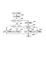
次に、図20から図22を参照して、図4のステップS12におけるステージ判別処理のフローについて説明する。ステージ判定処理においてロータ位置判定回路75は、まず、U1からV1へ通電する(図20:ステージ判別1のステップS101)。次に、ロータ位置判定回路75は、U1からV1への通電時に計測した電圧W2-N2と正の基準電圧+Vrefとを比較する(ステップS102)。電圧W2-N2が+Vrefより大きくない場合(ステップS102:N)、ロータ位置判定回路75は、電圧W2-N2と負の基準電圧-Vrefとを比較する(ステップS103)。電圧W2-N2が-Vrefより小さくない場合(ステップS103:N)、ロータ位置判定回路75は、図21に示したステージ判別2へ処理を進める(ステップS104)。
一方、電圧W2-N2が-Vrefより小さい場合(ステップS103:Y)、ロータ位置判定回路75は、W1からU1へ通電する(ステップS105)。続いて、ロータ位置判定回路75は、W1からU1への通電時に計測した電圧V2-N2と正の基準電圧+Vrefとを比較する(ステップS106)。電圧V2-N2が+Vrefより大きくない場合(ステップS106:N)、ロータ位置判定回路75は、位置関係(ロータ位置)がステージ5であると確定し(ステップS111)、処理を終了する(ステップS110)。一方、電圧V2-N2が+Vrefより大きい場合(ステップS106:Y)、ロータ位置判定回路75は、ステップS101でU1からV1への通電時に計測した電圧W2-N2の絶対値と、ステップS105でW1からU1への通電時に計測した電圧V2-N2の絶対値とを比較する(ステップS107)。ただし、図20に示したフローでは、ステップS107で比較される電圧V2-N2の正負の符号は、ステップS106の判定で正であることが確定しているので、ステップS107の判定処理では電圧W2-N2の絶対値と電圧V2-N2とを比較する。電圧W2-N2の絶対値が電圧V2-N2の絶対値以上である場合(ステップS107:Y)、ロータ位置判定回路75は、位置関係がステージ5であると確定し(ステップS108)、処理を終了する(ステップS110)。他方、電圧W2-N2の絶対値が電圧V2-N2の絶対値以上でない場合(ステップS107:N)、ロータ位置判定回路75は、位置関係がステージ6であると確定し(ステップS109)、処理を終了する(ステップS110)。
一方、ステップS102において、電圧W2-N2が+Vrefより大きい場合(ステップS102:Y)、ロータ位置判定回路75は、V1からW1へ通電する(ステップS112)。続いて、ロータ位置判定回路75は、V1からW1への通電時に計測した電圧U2-N2と負の基準電圧-Vrefとを比較する(ステップS113)。電圧V2-N2が-Vrefより小さくない場合(ステップS113:N)、ロータ位置判定回路75は、位置関係がステージ4であると確定し(ステップS114)、処理を終了する(ステップS110)。一方、電圧U2-N2が-Vrefより小さい場合(ステップS113:Y)、ロータ位置判定回路75は、ステップS101でU1からV1への通電時に計測した電圧W2-N2の絶対値と、ステップS112でV1からW1への通電時に計測した電圧U2-N2の絶対値とを比較する(ステップS115)。ただし、図20に示したフローでは、ステップS115で比較される電圧W2-N2の正負の符号は、ステップS102の判定で正であることが確定しているので、ステップS115の判定処理では電圧U2-N2の絶対値と電圧W2-N2とを比較している。電圧W2-N2の絶対値が電圧U2-N2の絶対値以上である場合(ステップS115:Y)、ロータ位置判定回路75は、位置関係がステージ4であると確定し(ステップS116)、処理を終了する(ステップS110)。他方、電圧W2-N2の絶対値が電圧U2-N2の絶対値以上でない場合(ステップS116:N)、ロータ位置判定回路75は、位置関係がステージ3であると確定し(ステップS117)、処理を終了する(ステップS110)。
ここで図20に示したステージ判別1の処理の概要をまとめると次のようになる。すなわち、「U1⇒V1」の通電にて「W2-N2」に電圧が誘起されればその極性と大きさから分岐する。「W2-N2」に誘起された電圧が「+」極性ならば、さらに「V1⇒W1」通電する。そして、「U2-N2」の電圧が、-Vrefより小さければステージ4が確定する。他方、「U2-N2」の電圧が、-Vrefより小さくなければ、「W2-N2」と絶対値比較して、「U2-N2」の電圧が大きくなければステージ4が確定し、大きければステージ3が確定する。また、「W2-N2」の極性が「-」で、-Vrefより小さければ、さらに「W1⇒U1」通電にて「V2-N2」の電圧が+Vref以下ならばステージ5が確定する。他方、「V2-N2」の電圧が、+Vrefより大きければ、「W2-N2」と絶対値比較し、「V2-N2」の電圧が大きければステージ6が確定し、大きくなければステージ5が確定する。また、「U1⇒V1」の通電にて「W2-N2」に電圧が誘起されなければステージ判別2を実行する。
一方、図21に示したステージ判別2では、ロータ位置判定回路75は、まず、U1からW1へ通電する(ステップS201)。次に、ロータ位置判定回路75は、U1からV1への通電時に計測した電圧V2-N2と正の基準電圧+Vrefとを比較する(ステップS202)。電圧V2-N2が+Vrefより大きくない場合(ステップS202:N)、ロータ位置判定回路75は、電圧V2-N2と負の基準電圧-Vrefとを比較する(ステップS203)。電圧V2-N2が-Vrefより小さくない場合(ステップS203:N)、ロータ位置判定回路75は、図22に示したステージ判別3へ処理を進める(ステップS204)。他方、電圧V2-N2が-Vrefより小さい場合(ステップS203:Y)、ロータ位置判定回路75は、位置関係がステージ3であると確定し(ステップS205)、処理を終了する(ステップS206)。
一方、ステップS202において、電圧V2-N2が+Vrefより大きい場合(ステップS202:Y)、ロータ位置判定回路75は、W1からV1へ通電する(ステップS207)。続いて、ロータ位置判定回路75は、ステップS201でU1からW1への通電時に計測した電圧V2-N2の絶対値と、ステップS207でW1からV1への通電時に計測した電圧U2-N2の絶対値とを比較する(ステップS208)。ただし、図21に示したフローでは、ステップS208で比較される電圧W2-N2の正負の符号は、ステップS202の判定で正であることが確定しているので、ステップS208の判定処理では電圧U2-N2の絶対値と電圧V2-N2とを比較している。電圧V2-N2の絶対値が電圧U2-N2の絶対値以上である場合(ステップS208:Y)、ロータ位置判定回路75は、位置関係がステージ5であると確定し(ステップS210)、処理を終了する(ステップS206)。他方、電圧V2-N2の絶対値が電圧U2-N2の絶対値以上でない場合(ステップS208:N)、ロータ位置判定回路75は、位置関係がステージ4であると確定し(ステップS209)、処理を終了する(ステップS206)。
ここで図21に示したステージ判別2の処理の概要をまとめると次のようになる。なお、ステージ判別2の処理が前提とする事項は次のとおりである。すなわち、「U1⇒V1」の通電にて「W2-N2」に誘起電圧が発生しなければ以下のことが判明する。すなわち、ロータ位置は、ステージ4とステージ5との境界上にある可能性がある。また、ロータ位置は、ステージ3とステージ4との境界上またはステージ5とステージ6との境界上にはない。上記を考慮し、ステージ判別2では、「U1⇒W1」に通電し「V2-N2」の誘起電圧を調べることで以下のことが分かる。
誘起電圧の発生があれば、ロータ位置は、誘起電圧が+極性の電圧ならばステージ4からステージ5上にあり、-極性の電圧ならばステージ3上にある。誘起電圧が発生しなければ、ロータ位置は、ステージ4とステージ5との境界上にはない。あるいは、ロータ位置は、ステージ2とステージ3との境界上にはない。あるいは、ロータ位置は、残る可能性として、ステージ1、2、6か、ステージ1とステージ2との境界、ステージ6とステージ1との境界上のどれかに絞り込まれる。この可能性については、ステージ判別3の処理で判定する。
一方、図22に示したステージ判別3では、ロータ位置判定回路75は、まず、V1からU1へ通電する(ステップ301)。次に、ロータ位置判定回路75は、V1からU1への通電時に計測した電圧W2-N2と正の基準電圧+Vrefとを比較する(ステップS302)。電圧W2-N2が+Vrefより大きい場合(ステップS302:Y)、ロータ位置判定回路75は、位置関係がステージ2であると確定し(ステップS303)、処理を終了する(ステップS304)。
他方、電圧W2-N2が+Vrefより大きくない場合(ステップS302:N)、ロータ位置判定回路75は、電圧W2-N2と負の基準電圧-Vrefとを比較する(ステップS305)。電圧W2-N2が-Vrefより小さくない場合(ステップS305:N)、ロータ位置判定回路75は、W1からV1へ通電する(ステップS306)。続いて、ロータ位置判定回路75は、ステップS301でV1からU1への通電時に計測した電圧W2-N2の絶対値と、ステップS306でW1からV1への通電時に計測した電圧U2-N2の絶対値とを比較する(ステップS307)。ここで、ステップS301の判定処理は、位置関係がステージ1とステージ6との境界付近にある場合に、位置関係がステージ1またはステージ6のどちらなのかを判定する処理である。また、ステージ1とステージ6との境界付近では、図7に示したように、W1からV1への通電時の電圧U2-N2は正であり、V1からU1への通電時の電圧W2-N2は負である。そこで、ステップS301の判定処理では電圧W2-N2の絶対値と電圧U2-N2とを比較する。電圧U2-N2の絶対値が電圧W2-N2の絶対値以上でない場合(ステップS307:N)、ロータ位置判定回路75は、位置関係がステージ1であると確定し(ステップS308)、処理を終了する(ステップS304)。他方、電圧W2-N2の絶対値が電圧V2-N2の絶対値以上である場合(ステップS307:Y)、ロータ位置判定回路75は、位置関係がステージ6であると確定し(ステップS309)、処理を終了する(ステップS304)。
一方、ステップS305において、電圧W2-N2が-Vrefより小さい場合(ステップS305:Y)、ロータ位置判定回路75は、W1からU1へ通電する(ステップS310)。続いて、ロータ位置判定回路75は、W1からU1への通電時に計測した電圧V2-N2と正の基準電圧+Vrefとを比較する(ステップS311)。電圧V2-N2が+Vrefより大きい場合(ステップS311Y)、ロータ位置判定回路75は、位置関係がステージ6であると確定し(ステップS312)、処理を終了する(ステップS304)。一方、電圧V2-N2が+Vrefより大きくない場合(ステップS311:N)、ロータ位置判定回路75は、位置関係がステージ1であると確定し(ステップS313)、処理を終了する(ステップS304)。
ここで図22に示したステージ判別3の処理の概要をまとめると次のようになる。「V1⇒U1」の通電にて「W2-N2」に誘起される電圧を調べることで以下のことが判明する。すなわち、ロータ位置は、誘起電圧の発生があれば、誘起電圧が+極性ならばステージ2上にあり、-極性ならばステージ1上またはステージ6とステージ1との境界上にある。一方、ロータ位置は、誘起電圧の発生がなければ、ステージ6とステージ1との境界上にはなく、ステージ1とステージ2との境界上またはステージ6上にある。
以上のようにして、ロータ位置判定回路75は図4のステップS12におけるステージ判別処理を実行する。
次に、図4において、CPU72は、ロータ位置判定回路75においてステージ判別処理が正常に終了したか否かを判定する(ステップS13)。一方、ステージ判別処理が正常に終了していない場合(ステップS13で「N」の場合)、CPU72は、ステップS12の判別処理を再度、実行する(ステップS11で「Y」からステップS12)。他方、ステージ判別処理が正常に終了していた場合(ステップS13で「Y」の場合)、CPU72は、ロータ位置判定回路75が判定したステージに対応した通電パターンで第1電力変換部61および第2電力変換部62のMOSFET(Q1)~(Q9)の通電制御を開始する(ステップS14)。その際、CPU72は、例えば、第1電力変換部61の通電角を180°に設定し、第2電力変換部62の通電角を120°以上180°未満に設定する。
次に、始動発電機1が回転を開始した後、ゼロクロス検出回路74が巻線部ACG2の出力電圧のゼロクロス点に基づきステージ信号を生成してCPU72に対して出力する(ステップS15)。そして、CPU72が、第1電力変換部および第2電力変換部に対して、ゼロクロス検出回路74によって検出されたステージに対応したパターンにて通電制御を行う(ステップS15)。
ここで、図23を参照して、スタータモータ始動制御時の回転時における巻線部ACG2の電圧波形について説明する。図23は、巻線部ACG2の巻線U2の出力電圧波形と、ロータ位置判定回路75による巻線U2の出力電圧のゼロクロス点の検出波形とを模式的に示した波形図である。この場合、ステップS14およびステップS15における第2電力変換部62の通電角は120°に設定している。図23において、ゼロクロス点の検出波形は、出力電圧のゼロクロス点において出力電圧の変化と同一方向で立ち上がりまたは立ち下がる。なお、巻線部ACG2の電圧波形には、相を切り替えるタイミング(破線の領域A1)でノイズが発生する。そのため、ロータ位置判定回路75では、切り替えタイミングでノイズをマスクしゼロクロス検出に支障が出ないようにすることが望ましい。ゼロクロス検出回路74は、巻線U2、V2およびW2の各出力電圧波形から各相の検出波形を生成し、各相の検出波形に基づきロータ位置を表すステージ信号を生成してCPU72に対して出力する。
次に、図4において、CPU72は、エンジンの始動が完了したか否かを判定する(ステップS16)。エンジンの始動が完了していない場合(ステップS16で「N」の場合)、CPU72は、ステップS15へ戻り、ゼロクロス検出回路74が検出したステージに対応したパターンにて通電制御を続行する(ステップS15)。エンジンの始動が完了していた場合(ステップS16で「Y」の場合)、CPU72は、モータ通電を停止し、スタータモータ始動制御を終了する(ステップS17)。
以上のように、スタータモータ制御においては、まず、第2電力変換部62のMOSFETを全てオフする。そして、第1電力変換部61を使って、巻線部ACG1に予め決められた通電パターンに従って、モータが動かない程度の短パルスを順次通電する。そして、もう一方の巻線部ACG2の巻線両端に誘起される電圧情報をもって、ロータ位置判定回路75が停止時におけるロータステージを判定する。次に、CPU72が、ロータ位置判定回路75により特定されたロータステージに対応した通電パターンを、巻線部ACG1および巻線部ACG2の各相に接続された第1電力変換部61と第2電力変換部62とのうち、第1電力変換部61に対しては180°、第2電力変換部62は120°以上180°未満の何れかの角度にて通電を開始する。そして、通電開始後は、ゼロクロス検出回路74が検出した巻線部ACG2のゼロクロスポイントから導出されるロータ位置情報に基づいてCPU72が巻線部ACG1および巻線部ACG2にエンジンの始動が完了するまで通電する。これによって、本実施形態では、始動時に、巻線部ACG2をゼロクロスポイント検出用に使用することが可能になるとともに、巻線部ACG1と巻線部ACG2との両方を始動巻線として使用することが可能になる。また、巻線部ACG1の通電モードを180°とし、巻線部ACG2の通電モードをゼロクロスポイントの検出が可能なできるだけ大きな通電角とすることで、巻線部ACG1と巻線部ACG2との両方を180°通電モードとする場合からの始動トルクの低減を極力抑えることができる。
次に、図24および図25を参照して、始動発電機1を発電機として動作させる場合について説明する。図24は、図1に示した始動発電制御装置100における発電制御の一例を示したフローチャートである。エンジン2の始動完了後、CPU72は、第2電力変換部62の各MOSFET(Q7)~(Q9)をオフする(ステップS21)。
次に、CPU72は、ゼロクロス検出回路74が巻線部ACG2の出力電圧のゼロクロス点に基づいて生成したステージ信号を入力する(ステップS22)。
ここで、図25を参照して、発電制御時の巻線部ACG2の電圧波形について説明する。図25は、巻線部ACG2の巻線U2の出力電圧波形と、ロータ位置判定回路75による巻線U2の出力電圧のゼロクロス点の検出波形とを模式的に示した波形図である。この場合、第2電力変換部62はオフ状態に制御されている。ゼロクロス点の検出波形は、出力電圧のゼロクロス点において出力電圧の変化と同一方向で立ち上がりまたは立ち下がる。ゼロクロス検出回路74は、図25に示したような巻線U2、V2およびW2の各出力電圧波形から各相の検出波形を生成し、各相の検出波形に基づきロータ位置を段階的に表すステージ信号を生成してCPU72に対して出力する。
次に、CPU72は、バッテリ9の電圧値に基づき第1電力制御部61の通電角を計算する(ステップS23)。 次に、CPU72は、第1電力変換部61から巻線部ACG1へステップS23で計算した遅角量に基づく遅角パターンを出力する(ステップS24)。そして、CPU72は、ステップS22へ戻り、上述した処理を再度実行する。
以上のように、発電制御においては、エンジン始動後に第2電力変換部62のMOSFETを全オフとすることで、余剰な発電電力の発生を防いでいる。また、ゼロクロス検出回路74によって、巻線部ACG2の巻線両端に発生する無負荷電圧のゼロクロスポイントからロータ位置を導出することで、巻線部ACG1の交流電圧を第1電力変換部61にて位相制御するに必要なタイミングを生成する。これによって、本実施形態によれば、バッテリ9や図示していない電装負荷に最適な電力を供給することができる。
以上のように、本実施形態によれば高価なセンサを用いず、かつサブコイルを用いることなく、簡易な方法で安価にロータの位置決めが可能となる。
また、本実施形態は、3相巻線(多相巻線)である巻線部ACG1と巻線部ACG2とが並列に配設された電機子部と、永久磁石からなる界磁部とを備えた始動発電機1(ACGスタータモータ)と、巻線部ACG1または巻線部ACG1および巻線部ACG2に接続され、交流および直流間の電力変換を行う第1電力変換部61と、巻線部ACG1の各端部に接続されている第1電力変換部61の各交流端子611、612および613と、巻線部ACG2の各端部との間に介挿され、各交流端子611、612および613に対して巻線部ACG2の各端部の接続および分離を行う複数のMOSFET(スイッチ素子)(Q7)~(Q9)とを備えている。この構成によれば、電力損失の低減等、始動発電機1の制御特性を容易に向上させることができる。
また、以上のように、本実施形態によれば、巻線部を例えば2分割して両方を使用する場合と片方を使用する場合とで使い分けることで、発電と電気負荷とのバランスを適正化することができる。この構成によれば、スタータモータのトルク特性を満たすように巻線仕様を設計したモータを、発電機として使用したときに電気負荷とのアンバランスによって発生する余剰電力を低減することができる。すなわち、巻線部の環流電流を減らし、巻線やパワーデバイス素子の発熱(電力損失)を小さくすることができる。よって、モータトルクを損なうことなく発電時の余剰電力を容易に削減することができる。これによってエンジン2の燃費向上やフリクションの低減が可能となる。
また、発電制御時に、環流電流を減らすことで電機子巻線とパワーデバイスの発熱を低減することができる。
次に、図26を参照して、本発明の第2の実施形態について説明する。図26は、本発明の第2の実施形態の始動発電制御装置100bの構成例を示したブロック図である。なお、図26において、図3に示したものと同一の構成には同一の符号を付けて説明を省略する。また、図26において、図3に示したものと基本的な機能が同一の構成には同一の符号の末尾に文字「a」を付加した符号を付けている。検出・判定回路部73の構成と動作は上記の実施形態と同一である。
第2の実施形態の始動発電制御装置100aは、図3に示した始動発電制御装置100と比較して次の点が異なる。すなわち、第2電力変換部62aが、MOSFET(Q10)~(Q12)を新たに備える。この場合、MOSFET(Q10)のドレインはMOSFET(Q7)のドレインに接続されている。MOSFET(Q11)のドレインはMOSFET(Q8)のドレインに接続されている。MOSFET(Q12)のドレインはMOSFET(Q9)のドレインに接続されている。そして、MOSFET(Q10)、MOSFET(Q11)およびMOSFET(Q12)の各ソースは、接地されている。
また、制御部7aにおいて、MOSFETゲートドライブ回路71aは、図3に示したMOSFETゲートドライブ回路71に対して、新たに設けたMOSFET(Q10)~(Q12)用の回路が追加されている。また、CPU72aは、図3に示したCPU72に対して、新たに設けたMOSFET(Q10)~(Q12)用にプログラムが追加されている。
第2の実施形態の始動発電制御装置100aによれば、負側のMOSFETを巻線部ACG1用と巻線部ACG2用とに2組設けることで、負側のMOSFETに流れる電流を制限し、各MOSFETの発熱を減らすことができる。
次に、図27を参照して、本発明の第3の実施形態について説明する。図27は、本発明の第3の実施形態の始動発電制御装置100bの構成例を示したブロック図である。なお、図27において、図3または図26に示したものと同一の構成には同一の符号を付けて説明を省略する。また、図27において、図3に示したものと基本的な機能が同一の構成には同一の符号の末尾に文字「b」を付加した符号を付けている。検出・判定回路部73の構成と動作は上記の各実施形態と同一である。
第3の実施形態の始動発電制御装置100bは、図3に示した始動発電制御装置100と比較して次の点が異なる。すなわち、第1電力変換部61bは、図3に示した第1電力変換部61に対して、MOSFET(Q13)(第1スイッチ素子)を新たに備えている。このMOSFET(Q13)は、正側直流端子614とバッテリ9に接続されている正側直流端子616との間に介挿されている。MOSFET(Q13)のドレインは正側直流端子614に接続され、MOSFET(Q13)のソースは正側直流端子616に接続されている。
第2電力変換部62bは、6個のMOSFET(Q17)~(Q19)および(Q10)~(Q12)を備え、3相ブリッジ直交変換部回路を構成する。また、直交変換部62bは、MOSFET(Q17)~(Q19)および(Q10)~(Q12)からなる3相ブリッジ直交変換部回路の直流入出力線の正側に正側直流端子624を備えるとともに、負側に負側直流端子625を備える。このMOSFET(Q17)~(Q19)および(Q10)~(Q12)からなる3相ブリッジ直交変換部回路は、巻線部ACG2の巻線U2、巻線V2および巻線W2を各交流端子621、622および623に接続し、直流および交流間の双方向に電力を変換する。
また、第2電力変換部62bは、正側直流端子624とバッテリ9に接続されている正側直流端子626との間にMOSFET(Q14)(第2スイッチ素子)を備えている。MOSFET(Q14)のドレインは正側直流端子624に接続され、MOSFET(Q14)のソースは正側直流端子626に接続されている。
なお、第2電力変換部62bは、図3に示した第2電力変換部62と比較して、MOSFET(Q7)~(Q9)が省略されている。
また、制御部7bにおいて、MOSFETゲートドライブ回路71bは、図3に示したMOSFETゲートドライブ回路71に対して、新たに設けたMOSFET(Q10)~(Q14)および(Q17)~(Q19)用の回路が追加されている。また、CPU72bは、図3に示したCPU72に対して、新たに設けたMOSFET(Q10)~(Q14)および(Q17)~(Q19)用にプログラムが変更されている。
第3の実施形態の始動発電制御装置100bでは、MOSFET(Q13)およびMOSFET(Q14)をオンまたはオフすることで、発電制御時に、巻線部ACG1のみから発電電力を出力させたり、巻線部ACG2のみから発電電力を出力させたり、あるいは、巻線部ACG1と巻線部ACG2との両方から発電電力を出力させたりという制御を行うことができる。
以上のように、第3の実施形態の始動発電制御装置100bによれば、巻線部を例えば2分割して両方を使用する場合と片方を使用する場合とで使い分けることで、発電と電気負荷とのバランスを適正化することができる。この構成によれば、スタータモータのトルク特性を満たすように巻線仕様を設計したモータを、発電機として使用したときに電気負荷とのアンバランスによって発生す余剰電力を低減することができる。すなわち、巻線部の環流電流を減らし、巻線やパワーデバイス素子の発熱(電力損失)を小さくすることができる。よって、モータトルクを損なうことなく発電時の余剰電力を容易に削減することができる。これによってエンジン2の燃費向上やフリクションの低減が可能となる。
また、巻線部ACG1と巻線部ACG2との仕様(ターン数、線径等)を異ならせることでモータ制御における発生トルクや発電制御における発電出力を、例えば、巻線部ACG1を使用する場合と、巻線部ACG2を使用する場合と、巻線部ACG1および巻線部ACG2を使用する場合の3段階で選択することができる。
以上のように、本発明の各実施形態によれば、巻線部ACG1および巻線部ACG2が並列に配置された始動発電機1が、エンジン2の始動に用いられる場合、および発電機として用いられる場合の双方において、巻線部ACG2をロータの位置を検出する検出巻線として用いるため、ホールセンサを設けずに、ロータの位置を高い精度で検出することができる。このため、高価なホールセンサを高い取付精度に対応して配置する必要がないため、価格が安くかつ高い精度でロータの検出が可能な始動発電機を提供することができる。
また、本発明の各実施形態によれば、巻線部ACG1(第1多相巻線)に複数の通電パターンで順次、線間電圧を印加したときに、巻線部ACG2(第2多相巻線)に発生する相電圧の値を検出することで、ロータの停止位置を判定することができる。これによれば電流検出を不要とすることができる。また、隣り合うステージの境界で電圧検出が困難になり、ステージ判定ができなくなる場合があるという課題に対しては、2つの異なる通電パターンを印加したときにそれぞれ検出された2つの異なる相電圧どうしを比較した結果に基づいてステージを判定するようにしたことで、境界上でも精度良くステージ判定することができる。
なお、本発明の実施形態は上記のものに限定されず、発明の要旨を逸脱しない範囲の設計等も含まれる。
例えば、ロータ位置判定回路75は、巻線部ACG1に対して異なる通電パターンで線間電圧を印加したときに検出された巻線部ACG2の異なる複数の相の相電圧を比較する際に、波高値の絶対値、相電圧の平均値の絶対値、相電圧の実効値などの相電圧の大きさを比較することができる。また、ロータ位置判定回路75は、異なる複数の相の相電圧を比較する際に、大きさに加えてパルス幅の長さを比較したり、あるいは、大きさに代えてパルス幅の長さを比較したりするようにしてもよい。
100、100a、100b 始動発電制御装置
1 始動発電機
ACG1、ACG2 巻線部
61、61b 第1電力変換部
62、62a 第2電力変換部
7、7a、7b 制御部
U1、V1、W1、U2、V2、W2 巻線
72 CPU
73 検出・判定回路部
74 ゼロクロス検出回路
75 ロータ位置判定回路
Q1~Q14、Q17~Q19 MOSFET
1 始動発電機
ACG1、ACG2 巻線部
61、61b 第1電力変換部
62、62a 第2電力変換部
7、7a、7b 制御部
U1、V1、W1、U2、V2、W2 巻線
72 CPU
73 検出・判定回路部
74 ゼロクロス検出回路
75 ロータ位置判定回路
Q1~Q14、Q17~Q19 MOSFET
Claims (3)
- 永久磁石からなる界磁部と、第1多相巻線および第2多相巻線が並列に配設された電機子部とを有する始動発電機と、
バッテリに接続される第1正側直流端子と、前記第1多相巻線に接続された複数の第1交流端子とを有し、直流および交流間で双方向に電力を変換する第1電力変換部と、
前記第2多相巻線に接続された複数の第2交流端子を有し、前記第2交流端子を介して入出力する電流を制御する第2電力変換部と、
前記第2多相巻線の出力電圧に基づき前記界磁部と前記電機子部との位置関係を検知し、検知した前記位置関係に応じて前記第1電力変換部と前記第2電力変換部とを制御する制御部と
を備え、
前記制御部が、前記第2交流端子を介して入出力する電流をオフした状態で、前記第1多相巻線における巻線の組および電圧印加の向きで決まる複数の通電パターンを順次選択して所定の線間電圧を印加したときに検出された前記第2多相巻線の相電圧の値と、異なる前記通電パターンで前記線間電圧を印加したときに検出された前記第2多相巻線の異なる複数の相の前記相電圧の比較結果とに基づき、前記始動発電機の停止時における前記位置関係を検知する
始動発電装置。 - 前記比較結果が、前記相電圧の絶対値の大きさを比較した結果である
請求項1に記載の始動発電装置。 - 永久磁石からなる界磁部と、第1多相巻線および第2多相巻線が並列に配設された電機子部とを有する始動発電機と、
バッテリに接続される第1正側直流端子と、前記第1多相巻線に接続された複数の第1交流端子とを有し、直流および交流間で双方向に電力を変換する第1電力変換部と、
前記第2多相巻線に接続された複数の第2交流端子を有し、前記第2交流端子を介して入出力する電流を制御する第2電力変換部と、
前記第2多相巻線の出力電圧に基づき前記界磁部と前記電機子部との位置関係を検知し、検知した前記位置関係に応じて前記第1電力変換部と前記第2電力変換部とを制御する制御部と
を用い、
前記制御部が、前記第2交流端子を介して入出力する電流をオフした状態で、前記第1多相巻線における巻線の組および電圧印加の向きで決まる複数の通電パターンを順次選択して所定の線間電圧を印加したときに検出された前記第2多相巻線の相電圧の値と、異なる前記通電パターンで前記線間電圧を印加したときに検出された前記第2多相巻線の異なる複数の相の前記相電圧の比較結果とに基づき、前記始動発電機の停止時における前記位置関係を検知する
始動発電方法。
Priority Applications (2)
| Application Number | Priority Date | Filing Date | Title |
|---|---|---|---|
| JP2016533215A JP6157042B1 (ja) | 2016-01-29 | 2016-01-29 | 始動発電装置および始動発電方法 |
| PCT/JP2016/052753 WO2017130394A1 (ja) | 2016-01-29 | 2016-01-29 | 始動発電装置および始動発電方法 |
Applications Claiming Priority (1)
| Application Number | Priority Date | Filing Date | Title |
|---|---|---|---|
| PCT/JP2016/052753 WO2017130394A1 (ja) | 2016-01-29 | 2016-01-29 | 始動発電装置および始動発電方法 |
Publications (1)
| Publication Number | Publication Date |
|---|---|
| WO2017130394A1 true WO2017130394A1 (ja) | 2017-08-03 |
Family
ID=59272957
Family Applications (1)
| Application Number | Title | Priority Date | Filing Date |
|---|---|---|---|
| PCT/JP2016/052753 Ceased WO2017130394A1 (ja) | 2016-01-29 | 2016-01-29 | 始動発電装置および始動発電方法 |
Country Status (2)
| Country | Link |
|---|---|
| JP (1) | JP6157042B1 (ja) |
| WO (1) | WO2017130394A1 (ja) |
Citations (3)
| Publication number | Priority date | Publication date | Assignee | Title |
|---|---|---|---|---|
| JP2004064893A (ja) * | 2002-07-29 | 2004-02-26 | Mitsubishi Electric Corp | 電動機およびその駆動装置 |
| JP2008141897A (ja) * | 2006-12-04 | 2008-06-19 | Suzuki Motor Corp | Dcブラシレスモータの駆動制御方法及び駆動制御装置 |
| JP2011050150A (ja) * | 2009-08-26 | 2011-03-10 | Yaskawa Electric Corp | 電動機駆動方法および電動車両用駆動装置 |
Family Cites Families (1)
| Publication number | Priority date | Publication date | Assignee | Title |
|---|---|---|---|---|
| JP2002186274A (ja) * | 2000-12-15 | 2002-06-28 | Mitsubishi Heavy Ind Ltd | ブラシレスdcモータの制御装置 |
-
2016
- 2016-01-29 JP JP2016533215A patent/JP6157042B1/ja active Active
- 2016-01-29 WO PCT/JP2016/052753 patent/WO2017130394A1/ja not_active Ceased
Patent Citations (3)
| Publication number | Priority date | Publication date | Assignee | Title |
|---|---|---|---|---|
| JP2004064893A (ja) * | 2002-07-29 | 2004-02-26 | Mitsubishi Electric Corp | 電動機およびその駆動装置 |
| JP2008141897A (ja) * | 2006-12-04 | 2008-06-19 | Suzuki Motor Corp | Dcブラシレスモータの駆動制御方法及び駆動制御装置 |
| JP2011050150A (ja) * | 2009-08-26 | 2011-03-10 | Yaskawa Electric Corp | 電動機駆動方法および電動車両用駆動装置 |
Also Published As
| Publication number | Publication date |
|---|---|
| JP6157042B1 (ja) | 2017-07-05 |
| JPWO2017130394A1 (ja) | 2018-02-01 |
Similar Documents
| Publication | Publication Date | Title |
|---|---|---|
| JP5504878B2 (ja) | 車両用発電機 | |
| US6787931B2 (en) | Starter generator for internal combustion engine | |
| JP2008545363A (ja) | 電動機 | |
| KR100402383B1 (ko) | 차량용 교류발전기 | |
| JP6484720B2 (ja) | 始動発電装置および始動発電方法 | |
| JPWO2008120737A1 (ja) | ブラシレスモータ、ブラシレスモータ制御システム、およびブラシレスモータ制御方法 | |
| JP6330105B1 (ja) | 始動発電装置および始動発電方法 | |
| CN106208848A (zh) | 电机驱动控制装置以及电机驱动控制方法 | |
| US20040080291A1 (en) | Control method of dynamo-electric machine for vehicle | |
| US10027252B2 (en) | Rotating electric machine system | |
| CN109936316B (zh) | 功率转换器的控制装置 | |
| JP6157042B1 (ja) | 始動発電装置および始動発電方法 | |
| JP6128721B2 (ja) | 始動発電装置、及び始動発電方法 | |
| JP4887890B2 (ja) | 車両用モータ装置 | |
| US7246029B2 (en) | Electric machine with actively controlled switches | |
| JP2006141143A (ja) | バッテリ充電装置 | |
| WO2016157386A1 (ja) | 始動発電装置、及び始動発電方法 | |
| CN114384296A (zh) | 电流检测装置 | |
| WO2016157381A1 (ja) | 始動発電装置、及び始動発電方法 | |
| JP2009273251A (ja) | モータ駆動装置 | |
| JP2019080405A (ja) | 電動機制御装置 |
Legal Events
| Date | Code | Title | Description |
|---|---|---|---|
| ENP | Entry into the national phase |
Ref document number: 2016533215 Country of ref document: JP Kind code of ref document: A |
|
| 121 | Ep: the epo has been informed by wipo that ep was designated in this application |
Ref document number: 16887980 Country of ref document: EP Kind code of ref document: A1 |
|
| NENP | Non-entry into the national phase |
Ref country code: DE |
|
| 122 | Ep: pct application non-entry in european phase |
Ref document number: 16887980 Country of ref document: EP Kind code of ref document: A1 |