WO2017127293A1 - Adhesive tape assembly and bonding product - Google Patents
Adhesive tape assembly and bonding product Download PDFInfo
- Publication number
- WO2017127293A1 WO2017127293A1 PCT/US2017/013348 US2017013348W WO2017127293A1 WO 2017127293 A1 WO2017127293 A1 WO 2017127293A1 US 2017013348 W US2017013348 W US 2017013348W WO 2017127293 A1 WO2017127293 A1 WO 2017127293A1
- Authority
- WO
- WIPO (PCT)
- Prior art keywords
- adhesive tape
- tensile
- removable adhesive
- bonding
- bonded
- Prior art date
- Legal status (The legal status is an assumption and is not a legal conclusion. Google has not performed a legal analysis and makes no representation as to the accuracy of the status listed.)
- Ceased
Links
Classifications
-
- C—CHEMISTRY; METALLURGY
- C09—DYES; PAINTS; POLISHES; NATURAL RESINS; ADHESIVES; COMPOSITIONS NOT OTHERWISE PROVIDED FOR; APPLICATIONS OF MATERIALS NOT OTHERWISE PROVIDED FOR
- C09J—ADHESIVES; NON-MECHANICAL ASPECTS OF ADHESIVE PROCESSES IN GENERAL; ADHESIVE PROCESSES NOT PROVIDED FOR ELSEWHERE; USE OF MATERIALS AS ADHESIVES
- C09J7/00—Adhesives in the form of films or foils
- C09J7/20—Adhesives in the form of films or foils characterised by their carriers
- C09J7/29—Laminated material
-
- C—CHEMISTRY; METALLURGY
- C09—DYES; PAINTS; POLISHES; NATURAL RESINS; ADHESIVES; COMPOSITIONS NOT OTHERWISE PROVIDED FOR; APPLICATIONS OF MATERIALS NOT OTHERWISE PROVIDED FOR
- C09J—ADHESIVES; NON-MECHANICAL ASPECTS OF ADHESIVE PROCESSES IN GENERAL; ADHESIVE PROCESSES NOT PROVIDED FOR ELSEWHERE; USE OF MATERIALS AS ADHESIVES
- C09J7/00—Adhesives in the form of films or foils
- C09J7/10—Adhesives in the form of films or foils without carriers
-
- B—PERFORMING OPERATIONS; TRANSPORTING
- B32—LAYERED PRODUCTS
- B32B—LAYERED PRODUCTS, i.e. PRODUCTS BUILT-UP OF STRATA OF FLAT OR NON-FLAT, e.g. CELLULAR OR HONEYCOMB, FORM
- B32B7/00—Layered products characterised by the relation between layers; Layered products characterised by the relative orientation of features between layers, or by the relative values of a measurable parameter between layers, i.e. products comprising layers having different physical, chemical or physicochemical properties; Layered products characterised by the interconnection of layers
- B32B7/04—Interconnection of layers
- B32B7/12—Interconnection of layers using interposed adhesives or interposed materials with bonding properties
-
- C—CHEMISTRY; METALLURGY
- C09—DYES; PAINTS; POLISHES; NATURAL RESINS; ADHESIVES; COMPOSITIONS NOT OTHERWISE PROVIDED FOR; APPLICATIONS OF MATERIALS NOT OTHERWISE PROVIDED FOR
- C09J—ADHESIVES; NON-MECHANICAL ASPECTS OF ADHESIVE PROCESSES IN GENERAL; ADHESIVE PROCESSES NOT PROVIDED FOR ELSEWHERE; USE OF MATERIALS AS ADHESIVES
- C09J7/00—Adhesives in the form of films or foils
- C09J7/20—Adhesives in the form of films or foils characterised by their carriers
-
- C—CHEMISTRY; METALLURGY
- C09—DYES; PAINTS; POLISHES; NATURAL RESINS; ADHESIVES; COMPOSITIONS NOT OTHERWISE PROVIDED FOR; APPLICATIONS OF MATERIALS NOT OTHERWISE PROVIDED FOR
- C09J—ADHESIVES; NON-MECHANICAL ASPECTS OF ADHESIVE PROCESSES IN GENERAL; ADHESIVE PROCESSES NOT PROVIDED FOR ELSEWHERE; USE OF MATERIALS AS ADHESIVES
- C09J2203/00—Applications of adhesives in processes or use of adhesives in the form of films or foils
- C09J2203/33—Applications of adhesives in processes or use of adhesives in the form of films or foils for batteries or fuel cells
-
- C—CHEMISTRY; METALLURGY
- C09—DYES; PAINTS; POLISHES; NATURAL RESINS; ADHESIVES; COMPOSITIONS NOT OTHERWISE PROVIDED FOR; APPLICATIONS OF MATERIALS NOT OTHERWISE PROVIDED FOR
- C09J—ADHESIVES; NON-MECHANICAL ASPECTS OF ADHESIVE PROCESSES IN GENERAL; ADHESIVE PROCESSES NOT PROVIDED FOR ELSEWHERE; USE OF MATERIALS AS ADHESIVES
- C09J2301/00—Additional features of adhesives in the form of films or foils
- C09J2301/30—Additional features of adhesives in the form of films or foils characterized by the chemical, physicochemical or physical properties of the adhesive or the carrier
- C09J2301/308—Additional features of adhesives in the form of films or foils characterized by the chemical, physicochemical or physical properties of the adhesive or the carrier the adhesive tape or sheet losing adhesive strength when being stretched, e.g. stretch adhesive
-
- Y—GENERAL TAGGING OF NEW TECHNOLOGICAL DEVELOPMENTS; GENERAL TAGGING OF CROSS-SECTIONAL TECHNOLOGIES SPANNING OVER SEVERAL SECTIONS OF THE IPC; TECHNICAL SUBJECTS COVERED BY FORMER USPC CROSS-REFERENCE ART COLLECTIONS [XRACs] AND DIGESTS
- Y02—TECHNOLOGIES OR APPLICATIONS FOR MITIGATION OR ADAPTATION AGAINST CLIMATE CHANGE
- Y02E—REDUCTION OF GREENHOUSE GAS [GHG] EMISSIONS, RELATED TO ENERGY GENERATION, TRANSMISSION OR DISTRIBUTION
- Y02E60/00—Enabling technologies; Technologies with a potential or indirect contribution to GHG emissions mitigation
- Y02E60/10—Energy storage using batteries
Definitions
- the present invention belongs to the technical field of tensile removable adhesive tapes, and particularly relates to an adhesive tape assembly and a bonding product.
- batteries in many mobile terminals are bonded to casings by way of double-sided tapes.
- the batteries need to be dismantled for the reasons of positioning inaccuracy and maintenance and the like, since the double-sided tapes are located between the batteries and the casings and thus cannot be taken down, an operator can only operate the batteries to pull the batteries down from the double- sided tapes.
- mobile terminals mostly use lithium batteries, wherein the lithium batteries bend easily and are damaged easily when being operated directly, and even the leakage of virulent electrolyte is possibly caused to lead to danger. For this reason, tensile removable adhesive tapes are available to fix the batteries in the mobile terminals.
- a tensile removable adhesive tape 1 contracts when being stretched, and thus bonding surfaces of the tensile removable adhesive tape 1 are subjected to forces perpendicular to the surfaces of substrates 9 and are separated from the substrates 9.
- the tensile removable adhesive tape 1 can be drawn out from between the two substrates 9, so that the substrates 9 are separated from each other.
- the tensile removable adhesive tape 1 contracts and is separated from the substrates 9, the tensile removable adhesive tape 1 further needs to move a certain distance relative to the substrates 9 before falling off from between the substrates 9. Due to the structural differences of the substrates 9, under many conditions, the tensile removable adhesive tape 1 can be stretched only at a specific stretching angle (namely an included angle between the stretching direction and the contact surface between the tensile removable adhesive tape 1 and the substrate 9). On this occasion, an edge portion (a right end of the lower surface of the substrate 9 on the upper side in FIG.
- An objective of the present invention is to provide an adhesive tape assembly.
- a tensile removable adhesive tape can be prevented from being broken in the removing process (even if the tensile removable adhesive tape is removed at a large stretching angle), so that the reliability of the tensile removable adhesive tape is improved.
- the adhesive tape assembly is used to bond to at least one substrate, and the adhesive tape assembly comprises:
- an intermediary layer which covers at least part of the bonding surface of the tensile removable adhesive tape and has a first surface and a second surface opposite to each other; wherein the first surface is used to bond to the substrate;
- the second surface is bonded to the bonding surface and at least part of the second surface is in direct contact with the bonding surface;
- the second surface has an Ra value between 0.1 ⁇ and 7 ⁇ .
- the second surface is provided with an Ra value between 0.15 ⁇ and 6 ⁇ .
- the adhesive tape assembly further comprises a low-viscosity layer, which is arranged between one end of the intermediary layer and the tensile removable adhesive tape, wherein at least one of both a bonding strength between the low-viscosity layer and the tensile removable adhesive tape and a bonding strength between the low-viscosity layer and the intermediary layer is smaller than that between the intermediary layer and the substrate.
- Another objective of the present invention is to provide a bonding product, wherein the bonding product is provided with a tensile removable adhesive tape.
- the tensile removable adhesive tape does not break easily when being stretched and removed (even if removed at a large stretching angle), and the reliability is high.
- the bonding product comprises:
- a first substrate which has a first to-be-bonded surface
- a tensile removable adhesive tape which has bonding surfaces, wherein a portion of the tensile removable adhesive tape is bonded to the first to-be-bonded surface, and another portion of the tensile removable adhesive tape extends outside the first to-be-bonded surface;
- an intermediary layer which is at least arranged between an edge portion of the first to-be-bonded surface and the tensile removable adhesive tape and has a first surface and a second surface opposite to each other, wherein at least part of the first surface is bonded to the edge portion of the first to-be-bonded surface; the second surface has an Ra value between 0.1 ⁇ and 7 ⁇ ; and the second surface opposite to the first surface bonded to the edge portion of the first to-be-bonded surface is in direct contact with the bonding surface.
- the bonding product further comprises a second substrate, and the second substrate is provided with a second to-be- bonded surface opposite to the first to-be-bonded surface; the two sides of the tensile removable adhesive tape have the bonding surfaces, and a portion of the tensile removable adhesive tape is bonded between the first to-be-bonded surface and the second to-be-bonded surface.
- the bonding product is a mobile terminal; the first substrate is a battery; and the second substrate is a casing of the mobile terminal.
- FIG. 1 is a schematic diagram of stretching and removing an existing tensile removable adhesive tape
- FIG. 2 is a schematic diagram of stretching and removing an existing tensile removable adhesive tape at a large stretching angle
- FIG. 3 is a sectional structure diagram of a tensile removable adhesive tape according to an embodiment of the present invention.
- FIG. 4 is a structural top view of a tensile removable adhesive tape in FIG. 3;
- FIG. 5 is a sectional structure diagram of stretching and removing a tensile removable adhesive tape in FIG. 3;
- FIG. 6 is a sectional structure diagram of another tensile removable adhesive tape according to an embodiment of the present invention.
- FIG. 7 is a sectional structure diagram of a further tensile removable adhesive tape according to an embodiment of the present invention.
- FIG. 8 is a sectional structure diagram of a bonding product using a tensile removable adhesive tape in FIG. 7 according to an embodiment of the present invention.
- FIG. 9 is a sectional structure diagram during the stretching and removal of a tensile removable adhesive tape in a bonding product in FIG. 8;
- FIG. 10 is another sectional structure diagram during the stretching and removal of a tensile removable adhesive tape in a bonding product in FIG. 8;
- markers of accompanying drawings are as follows: a tensile removable adhesive tape 1 ; a bonding surface 11 ; an intermediary layer 2; a first surface 21 ; a second surface 22, a pressure-sensitive adhesive 219; a low- viscosity layer 3; a non- viscous layer 4; substrates 9; a first substrate 91; and a second substrate 92.
- Tensile removable adhesive tape refers to an adhesive tape which can be separated from substrates by means of a tensile force exerted to the tensile removable adhesive tape along a length direction thereof after the tensile removable adhesive tape is bonded to the substrates.
- Stretching angle refers to an included angle between a motion direction of actually stretching a tensile removable adhesive tape and a contact surface between the tensile removable adhesive tape and a substrate.
- Pressure-sensitive adhesive refers to a substance capable of being bonded to a substrate, and at least meets the following conditions at an environment temperature (5°C to 40°C): (1) the pressure-sensitive adhesive has durable viscosity; (2) the bonding can be performed under pressure by a finger; (3) the pressure-sensitive adhesive can change its shape so as to adhere to the substrate; and (4) the cohesion strength of the pressure- sensitive adhesive is enough to make the pressure-sensitive adhesive basically removed from the substrate.
- Mobile terminal refers to a device capable of being carried by users to be used during movement and having calculation processing capability, and the “mobile terminal” includes but is not limited to a mobile phone, a tablet computer (e.g., an iPad), a notebook computer, etc.
- the embodiment of the present invention provides an adhesive tape assembly which is used to bond to at least one substrate 9; the adhesive tape assembly comprises:
- a tensile removable adhesive tape 1 which has bonding surfaces 11;
- an intermediary layer 2 which covers at least part of the bonding surface 1 1 of the tensile removable adhesive tape 1 and has a first surface 21 and a second surface 22 opposite to each other;
- the first surface 21 is used to bond to the substrate 9;
- the second surface 22 is bonded to the bonding surface 11 and at least part of the second surface 22 is in direct contact with the bonding surface 11;
- the second surface 22 has an Ra value between 0.1 ⁇ and 7 ⁇ .
- the adhesive tape assembly according to an embodiment of the present invention comprises a conventional tensile removable adhesive tape 1, and at least one surface of the tensile removable adhesive tape 1 has bonding surfaces 11 (namely has viscous surfaces) for being bonded to substrates 9.
- At least a portion of the bonding surface 1 1 is covered with an intermediary layer 2, and one side of the intermediary layer 2 towards the bonding surface 1 1 is a second surface 22; the second surface 22 has a specific roughness; that is, the Ra value (arithmetical mean deviation of the profile) of the second surface is between 0.1 ⁇ and 7 ⁇ ; at least part of the second surface 22 directly contacts the bonding surface 1 1; the other side of the intermediary layer 2 is a first surface 21, and the first surface 21 is used to bond to substrates 9.
- the intermediary layer 2 is located between the tensile removable adhesive tape 1 and the substrate 9 and becomes an intermediary for the tensile removable adhesive tape and the substrate, and the second surface 22 having a specific roughness may contact the tensile removable adhesive tape 1 (the bonding surface 11 thereof).
- the tensile removable adhesive tape 1 when the tensile removable adhesive tape 1 is stretched, the tensile removable adhesive tape 1 may be separated from the intermediary layer 2 and slide on the second surface 22; that is, the original sliding of the tensile removable adhesive tape 1 on the substrate 9 becomes the sliding on the second surface 22.
- the intermediary layer 2 can lower the sliding resistance undergone by the tensile removable adhesive tape 1 when the tensile removable adhesive tape 1 is stretched and removed (particularly when the stretching angle is large), so that the tensile removable adhesive tape 1 is prevented from being broken, and the reliability of the adhesive tape assembly is improved.
- the reasons the sliding resistance between the surface having the specific roughness and the tensile removable adhesive tape 1 is low is possibly due to the following (the following description is not intended to limit the action principle of the present invention): when the tensile removable adhesive tape 1 is stretched, surface molecules of the tensile removable adhesive tape 1 are highly oriented and surface undulation is eliminated to a large extent; that is, the surface of the tensile removable adhesive tape 1 becomes a smooth surface very low in roughness, at this time if a surface contacting the surface of the tensile removable adhesive tape is also very smooth, the contact area between them is very large, so that it leads to the situations that the tensile removable adhesive tape 1 still having a certain viscosity can be fully bonded to this surface, and the sliding resistance is increased.
- the tensile removable adhesive tape 1 is easily scratched by a peak of the rough structure in the sliding process, so that the sliding resistance is increased and the tensile removable adhesive tape 1 breaks easily.
- the impact of the above two aspects can be balanced, the sliding resistance is lowered to be minimum, and to the largest extent the tensile removable adhesive tape 1 is prevented from being broken.
- the second surface 22 is provided with an Ra value between 0.15 ⁇ and 6 ⁇ .
- the second surface 22 preferably has an Ra value between 0.15 ⁇ and 6 ⁇ , more preferably has an Ra value between 0.2 ⁇ and 5 ⁇ , and further preferably has an Ra value between 0.5 ⁇ and 4 ⁇ .
- the tensile removable adhesive tape 1 may be any conventional tensile removable adhesive tape product, e.g., a 6701-150 type tensile removable adhesive tape of 3M Company (St. Paul, Minnesota, US), therefore it is no longer described in detail herein.
- each side of the tensile removable adhesive tape 1 in each accompanying drawing is completely a bonding surface 11, it should be understood that it is also feasible if only part of the position of one side of the tensile removable adhesive tape 1 is a bonding surface 11 while the remaining positions has no viscosity.
- one end of the tensile removable adhesive tape 1 can have no viscosity, so as to serve as a handle for performing stretching.
- the above intermediary layer 2 may be any conventional film layer, as long as one side of the intermediary layer can be bonded to the substrate 9, and the other side has a specific roughness.
- the intermediary layer 2 can be formed by polymer materials, such as polyimide, polyethylene glycol terephthalate and polycarbonate, therefore it is no longer described in detail herein.
- the thickness of the intermediary layer 2 is generally between several ⁇ and hundreds of ⁇ , e.g., between 5 ⁇ and 800 ⁇ , preferably between 10 ⁇ and 500 ⁇ , more preferably between 20 ⁇ and 200 ⁇ , and further preferably between 25 ⁇ and 100 ⁇ .
- the first surface 21 is provided with a pressure-sensitive adhesive 219 or a double-sided tape.
- the first surface 21 is preferably provided with the pressure-sensitive adhesive 219 or the double-sided tape.
- the pressure-sensitive adhesive 219 may be a conventional acrylate pressure-sensitive adhesive, polyurethane pressure-sensitive adhesive, polyvinyl chloride, etc., therefore it is no longer described in detail herein.
- the first surface 21 has no adhesive while the adhesive or the double-sided tape is disposed at the to-be-bonded position of the substrate 9.
- the two sides of the tensile removable adhesive tape 1 have bonding surfaces 11, wherein the intermediary layer 2 is bonded to only one of the bonding surfaces 1 1.
- the two sides of the tensile removable adhesive tape 1 may have bonding surfaces 11, it is because the tensile removable adhesive tape 1 is usually used on the occasion that it is inconvenient to directly tear the adhesive from the substrates 9, while on this occasion, the adhesive is generally bonded between the two substrates 9; thus, preferably, the two sides of the tensile removable adhesive tape 1 can be bonded.
- it generally can be determined in advance which direction the tensile removable adhesive tape 1 should be stretched for example, in FIG. 10, the tensile removable adhesive tape can only be stretched upwards
- the tensile removable adhesive tape 1 slides only on the substrate 9 (e.g., a first substrate 91 in FIG. 10) on one side close to the stretching direction, so the tensile removable adhesive tape 1 only needs to be provided with the intermediary layer 2 on this side.
- At least one end of the tensile removable adhesive tape 1 has no intermediary layer 2.
- At least one end of the tensile removable adhesive tape 1 is not provided with the intermediary layer 2. It is because when the tensile removable adhesive tape 1 is removed, first the tensile removable adhesive tape 1 needs to be separated from the intermediary layer 2, so as to guarantee that the tensile removable adhesive tape 1 can slide on the intermediary layer 2 to reduce a sliding resistance. If the end of the tensile removable adhesive tape 1 is also provided with the intermediary layer 2, as shown in FIG. 6, the ends of the tensile removable adhesive tape 1 and the intermediary layer 2 are flush, and accordingly at this time it is very difficult to separate the tensile removable adhesive tape 1 and the intermediary layer 2 at the ends.
- the size of a portion of the second surface 22 directly contacting the bonding surface 11 is at least 5 mm.
- the second surface 22 directly contacting the bonding surface 11 is at least 5 mm long (there can further be other structures arranged between part of the second surface 22 and the bonding surface 11). It is because during stretching, only the sliding resistance between the edge portion of the substrate 9 and the tensile removable adhesive tape 1 is large; thus, at least at this position, there must be the intermediary layer 2 (the second surface 22) directly contacting the bonding surface 11. It is found in the present invention that the foregoing portion having high sliding resistance generally has a length within 5 mm, and accordingly the second surface 22 directly contacting the bonding surface 11 should be at least 5 mm long. Certainly, it is also feasible if the second surface 22 directly contacting the bonding surface 11 has a greater length so as to achieve a better effect of reducing the sliding resistance.
- the intermediary layer 2 on the bonding surface 11 where the intermediary layer 2 is bonded, along the length direction of the tensile removable adhesive tape 1, the intermediary layer 2 only covers a portion of the bonding surface 1 1; or, on the bonding surface 11 where the intermediary layer 2 is bonded, along the length direction of the tensile removable adhesive tape 1, the intermediary layer 2 completely covers the bonding surface 1 1.
- the intermediary layer 2 may, as shown in FIG. 3, only cover a portion of the bonding surface 11. It is because as described above, the portion having a high sliding resistance is actually has a small length; thus, as long as the bonding surface 11 on this portion is provided with the intermediary layer 2, at the remaining position the bonding surface 11 of the tensile removable adhesive tape 1 is still directly bonded to the substrates 9, and it can be guaranteed as far as possible that the original bonding performance of the tensile removable adhesive tape 1 is unchanged.
- the intermediary layer 2 completely covers the bonding surface 11.
- the intermediary layer 2 is only located on part of the position of the tensile removable adhesive tape 1, careful alignment must be performing during attachment, so as to guarantee that the intermediary layer 2 is located on the edge portion of the substrate 9 (or else the intermediary layer 2 cannot achieve an effect of reducing sliding resistance), but the operation difficulty is very high. If the intermediary layer 2 covers the whole bonding surface 11, the operation is simpler.
- the size of the intermediary layer 2 is greater than or equal to the width of the tensile removable adhesive tape 1.
- the second surface 22 should cover the whole width range of the bonding surface 11; that is, as shown in FIG. 4, the intermediary layer 2 should be as wide as or be wider than the tensile removable adhesive tape 1.
- the intermediary layer 2 can also achieve a certain effect of reducing the sliding resistance.
- the width of the intermediary layer 2 is at least should be 30% that of the tensile removable adhesive tape 1, more preferably at least 50%, and further preferably at least 80%.
- the intermediary layer 2 is preferably should be arranged in the middle of the tensile removable adhesive tape 1 in the width direction.
- the adhesive tape assembly further comprises a low-viscosity layer 3 which is arranged between one end of the intermediary layer 2 and the tensile removable adhesive tape 1 ; and at least one of a bonding strength between the low- viscosity layer 3 and the tensile removable adhesive tape 1 and a bonding strength between the low-viscosity layer 3 and the intermediary layer 2 is smaller than that between the intermediary layer 2 and the substrate 9. That is, as shown in FIG.
- the low-viscosity layer 3 may further be arranged between one end of the intermediary layer 2 and the tensile removable adhesive tape 1 (obviously, at the position of the low-viscosity layer 3, the second surface 22 does not directly contact the bonding surfaces 11), the low-viscosity layer 3 has a low bonding strength, and thus it is guaranteed that the bonding strength between the low-viscosity layer and the tensile removable adhesive tape 1 and/or the bonding strength between the low-viscosity layer and the intermediary layer 2 are/is lower than that between the intermediary layer 2 and the substrate 9.
- the effect of the low-viscosity layer 3 is to make a separation stress between the intermediary layer 2 and the tensile removable adhesive tape 1 smaller than a bonding force between the intermediary layer 2 and the substrate 9, so that in the removing process, it can be guaranteed that the tensile removable adhesive tape 1 is certainly separated from the intermediary layer 2, and the situation where the intermediary layer 2 is stripped from the substrate 9 along with the tensile removable adhesive tape is avoided.
- the bonding strength between the low-viscosity layer 3 and the tensile removable adhesive tape 1 is greater than that between the low-viscosity layer 3 and the intermediary layer 2.
- the bonding strength between the low-viscosity layer 3 and the tensile removable adhesive tape 1 is large, while the bonding strength between the low-viscosity layer 3 and the intermediary layer 2 is small.
- the tensile removable adhesive tape 1 is separated from the intermediary layer 2
- the low- viscosity layer 3 is certainly bonded to the tensile removable adhesive tape 1 and separated from the intermediary layer 2, along with the continuous stretching of the tensile removable adhesive tape 1, the low-viscosity layer 3 is taken away (as shown in FIG. 10), and thus the sliding of the tensile removable adhesive tape 1 on the intermediary layer 2 is not affected.
- the foregoing low-viscosity layer 3 may be an existing low-viscosity film or low-viscosity coating.
- the low-viscosity layer 3 since the surface (the second surface 22) of the intermediary layer 2 contacting the low-viscosity layer 3 has no viscosity, the low-viscosity layer 3 may also be a single-sided tape, so that one viscous surface of the low-viscosity layer 3 is utilized to bond the intermediary layer 2.
- the bonding strength between the low-viscosity layer 3 and the tensile removable adhesive tape 1 is greater than that between the low-viscosity layer 3 and the intermediary layer 2, when the single-sided tape is taken as the low-viscosity layer 3, a stripping strength between the single-sided tape and the intermediary layer 2 cannot be too high, usually may be between 1 g/inch and 200 g/inch, more preferably between 1 g/inch and 100 g/inch, and further preferably between 0.5 g/inch and 50 g/inch.
- the adhesive tape assembly further comprises a non-viscous layer 4 which is arranged on at least one side of at least one end of the tensile removable adhesive tape 1, and the surface of the non- viscous layer 4 far away from the tensile removable adhesive tape 1 has no viscosity.
- the end of the tensile removable adhesive tape 1 may further be provided with a layer with the outer side having no viscosity (the inner side of the layer may be viscous so as to be bonded to the tensile removable adhesive tape 1).
- the inner side of the layer may be viscous so as to be bonded to the tensile removable adhesive tape 1).
- this end may be provided with a non-viscous layer 4 (whose effect is similar to a release film).
- the position and length and the like of the non-viscous layer 4 can be determined according to concrete requirements, e.g., if as shown in FIG.
- the end of the tensile removable adhesive tape 1 is bent and bonded to a first substrate 91, only one unbonded side of the tensile removable adhesive tape 1 needs to be provided with the non- viscous layer 4.
- the non-viscous layer 4 may be a conventional non-viscous film (such as a release film), non-viscous film coating, single-sided tape, etc., therefore it is no longer described in detail herein.
- the preceding low-viscosity layer 3 and non-viscous layer 4 are drawn simultaneously drawn in FIGs. 7 to 10, there is no necessary connection between the low- viscosity layer 3 and non-viscous layer 4.
- the low- viscosity layer 3 and the non-viscous layer 4 may be present simultaneously, or only one of both may be present.
- a conventional release film or release paper may further be arranged, and is used for protecting the bonding surface 11 when the tensile removable adhesive tape is unused, and protecting the bonding surface from accidental bonding.
- the intermediary layer 2, the low- viscosity layer 3 and the non-viscous layer 4 and the like are recessed into the tensile removable adhesive tape 1; however, this is only used for schematically indicating that on which side of the tensile removable adhesive tape 1 these structures should be located, and does not represent that the tensile removable adhesive tape 1 is actually provided with recesses for accommodating these structures.
- the embodiment of the present invention further provides a bonding product, and the bonding product comprises:
- a first substrate 91 which has a first to-be-bonded surface
- a tensile removable adhesive tape 1 which has bonding surfaces 1 1, wherein a portion of the tensile removable adhesive tape 1 is bonded to the first to-be-bonded surface, and another portion of the tensile removable adhesive tape extends outside the first to-be-bonded surface;
- an intermediary layer 2 which is at least arranged between an edge portion of the first to-be-bonded surface and the tensile removable adhesive tape 1 and has a first surface 21 and a second surface 22 opposite to each other, wherein at least part of the first surface 21 is bonded to the edge portion of the first to-be-bonded surface; the second surface 22 has an Ra value between 0.1 ⁇ and 7 ⁇ , and the second surface 22 opposite to the first surface 21 bonded to the edge portion of the first to-be-bonded surface is in direct contact with the bonding surface 11.
- the embodiment of the present invention provides a bonding product comprising the tensile removable adhesive tape 1 and the intermediary layer 2.
- the first to-be-bonded surface of the first substrate 91 is provided with the tensile removable adhesive tape 1
- the intermediary layer 2 is arranged at least between the edge portion of the first to-be-bonded surface and the tensile removable adhesive tape 1; furthermore, at least the second surface 22 at the position of the edge portion directly contacts the bonding surface 11, so as to guarantee that when the tensile removable adhesive tape 1 is stretched and removed, the intermediary layer 2 can achieve effects of reducing a sliding resistance and preventing the tensile removable adhesive tape 1 from being broken.
- the bonding product may be obtained by bonding the adhesive tape assembly to the first substrate 91.
- the bonding product may also be obtained.
- the first substrate 91 further comprises a side portion connected with the first to-be-bonded surface; the tensile removable adhesive tape 1 is at least partially bonded to the side portion; and the intermediary layer 2 is also arranged between the side portion and the tensile removable adhesive tape 1.
- the side of the first substrate 91 may also be provided with the tensile removable adhesive tape 1 and the intermediary layer 2. It is because as shown in FIG. 8, under many conditions the tensile removable adhesive tape 1 also needs to be bonded to the side of the first substrate 91 ; when the stretching angle is very large (e.g., close to 90 degrees), a high sliding resistance is also generated between the side of the first substrate 91 and the tensile removable adhesive tape 1, and thus this position is preferably also provided with the intermediary layer 2.
- the bonding product further comprises a second substrate 92, and the second substrate is provided with a second to- be-bonded surface opposite to the first to-be-bonded surface; the two sides of the tensile removable adhesive tape 1 have the bonding surfaces 11, and a portion of the tensile removable adhesive tape 1 is bonded between the first to-be-bonded surface and the second to-be-bonded surface.
- the adhesive tape assembly enables the first substrate 91 and the second substrate 92 to be bonded together, and thus a portion of the tensile removable adhesive tape 1 should be located between the two to-be-bonded surfaces.
- at least one end of the tensile removable adhesive tape 1 also needs to be located outside the two to-be-bonded surfaces.
- the bonding product may also include such structures as the low-viscosity layer 3 and the non-viscous layer 4, and the existence of these structures does not affect functions of the tensile removable adhesive tape 1.
- the bonding product is provided with the low-viscosity layer 3, the low-viscosity layer 3 only needs to be located at one end of the intermediary layer 2; e.g., the low-viscosity layer 3 may exist only at a position corresponding to the upper surface (the side may also be available) of the first substrate 91, and does not exist at a position corresponding to the bottom surface of the first substrate 91.
- the bonding product is provided with the non-viscous layer 4, the non-viscous layer 4 should be located outside the two substrates for fear that the bonding of the substrates is affected.
- the bonding product is a mobile terminal; the first substrate 91 is a battery; and the second substrate 92 is a casing of the mobile terminal.
- the present invention is particularly suitable for fixing a battery of a mobile terminal (such as a mobile phone, a tablet computer, a notebook computer, etc.); specifically, the battery is bonded to a casing of the mobile terminal.
- a mobile terminal such as a mobile phone, a tablet computer, a notebook computer, etc.
- the battery is bonded to a casing of the mobile terminal.
- the end of the tensile removable adhesive tape 1 is stretched, so that the tensile removable adhesive tape 1 is separated from the two substrates and the intermediary layer 2, and falls off from between the two substrates; in the stretching process, on the edge portion of the substrate 9 (at the right end of the lower surface of the first substrate 91), the tensile removable adhesive tape 1 slides on the intermediary layer 2, and the tensile removable adhesive tape 1 is subjected to a small sliding resistance and does not fracture easily.
- the battery the first substrate 91
- the intermediary layer 2 remaining on the battery is torn down, so that the battery is dismantled.
- a method for testing intermediary layers comprises cutting the intermediary layers into slices of 10 cm ⁇ 10 cm and laying the slices on a glass plate, using single-sided tapes to fix both sides, using a TR-200 type roughness tester of Beijing Time High Technology Co., Ltd. (Beijing, China) to test its roughness (Ra value), testing a stroke of 4 mm each time, and testing 5 data for each intermediary layer. ) Mechanical stretching
- a mechanical device is utilized to stretch the tensile removable adhesive tape in the bonding product, to test maximum tensile stress of the tensile removable adhesive tape and whether the tensile removable adhesive tape breaks, and the process specifically comprises:
- the tensile removable adhesive tape in the bonding product is stretched manually, to test whether the tensile removable adhesive tape breaks, and the process specifically comprises:
- the tensile removable adhesive tape to the bottom surface and side of the battery and reserving a handle of 10 mm, wherein on the bottom surface edge portion and side of the battery, the tensile removable adhesive tape is arranged on the intermediary layer (and contacts with the second surface of the intermediary layer), and at the remaining position of the bottom surface of the battery the tensile removable adhesive tape is directly bonded to the battery.
- PI polyimide
- PI polyimide
- a polyimide (PI) original film with a thickness of 25 ⁇ produced by RayiTEK Hi-Tech Film Co., Ltd. (Shenzhen, Guangdong, China) directly serves as an intermediary layer without polishing.
- PET polyethylene terephthalate
- PET polyethylene terephthalate
- PET polyethylene terephthalate
- a 7585 type label material produced by 3M Company directly serves as an intermediary layer without polishing.
- a 57817 type label material produced by 3M Company directly serves as an intermediary layer without polishing.
- An ATL battery film produced by Beijing Huawei Technology Co., Ltd. directly serves as an intermediary layer without polishing.
- a mechanical stretching method is similar as described above; the difference is that a two-sided tape, an intermediary layer and an anodized aluminum block are not used, and the tensile removable adhesive tape is directly arranged between the battery and the stainless steel plate.
- a manual stretching method is similar as described above; the difference is that an intermediary layer is not used, and the tensile removable adhesive tape is directly bonded to the surface of the battery.
- a 1002 BO type automobile black film produced by 3M Company directly serves as an intermediary layer without polishing.
- Embodiment 7 7.94 8.24 8.73 7.65 6.91 7.89
- Embodiment 8 8.26 7.55 9.15 7.13 8.81 8.18
- the Ra value of the Ra value of the second surface of the intermediary layer is within the range of 0.1 ⁇ to 7 ⁇ , except that individual samples in Embodiment 8 with the maximum Ra value break, all other tensile removable adhesive tapes are removed smoothly without breaking. This indicates that the roughness within the above range can indeed effectively prevent the tensile removable adhesive tape from being broken. Moreover, if the Ra value is too large, it is unfavorable for preventing breakage of the tensile removable adhesive tape, and thus the Ra value of the second surface of the above intermediary layer is preferably less than 6 ⁇ , and more preferably less than 5 ⁇ .
Landscapes
- Chemical & Material Sciences (AREA)
- Organic Chemistry (AREA)
- Adhesive Tapes (AREA)
- Adhesives Or Adhesive Processes (AREA)
Abstract
The present invention provides an adhesive tape assembly and a bonding product in the field of stretch removable tape. The adhesive tape assembly won't break when it is stretched to remove. The adhesive tape assembly it is used for bonding to a base, it comprising: a stretch removable tape having an adhesive surface; and a intermediary layer having a first surface and a second surface opposite to each other, and the intermediary layer at least covers a portion of the adhesive surface of the stretch removable tape; wherein, the first surface is used for bonding to the base; the second surface is bonded onto the adhesive surface of the stretch removable tape, and at least part of the second surface is in direct contact with the adhesive surface of the stretch removable tape; the second surface has a Ra value between 0.1 μm and 7 μm.
Description
ADHESIVE TAPE ASSEMBLY AND BONDING PRODUCT
TECHNICAL FIELD
The present invention belongs to the technical field of tensile removable adhesive tapes, and particularly relates to an adhesive tape assembly and a bonding product.
BACKGROUND
For convenience and attractiveness and the like, batteries in many mobile terminals (such as a mobile phone, a tablet computer, a notebook computer, etc.) are bonded to casings by way of double-sided tapes. When the batteries need to be dismantled for the reasons of positioning inaccuracy and maintenance and the like, since the double-sided tapes are located between the batteries and the casings and thus cannot be taken down, an operator can only operate the batteries to pull the batteries down from the double- sided tapes. However, mobile terminals mostly use lithium batteries, wherein the lithium batteries bend easily and are damaged easily when being operated directly, and even the leakage of virulent electrolyte is possibly caused to lead to danger. For this reason, tensile removable adhesive tapes are available to fix the batteries in the mobile terminals.
As shown in FIG. 1, a tensile removable adhesive tape 1 contracts when being stretched, and thus bonding surfaces of the tensile removable adhesive tape 1 are subjected to forces perpendicular to the surfaces of substrates 9 and are separated from the substrates 9. Thus, as long as one end of the tensile removable adhesive tape 1 remains outside the substrates 9 (such as a battery and a casing), the tensile removable adhesive tape 1 can be drawn out from between the two substrates 9, so that the substrates 9 are separated from each other.
As shown in FIG. 2, after the tensile removable adhesive tape 1 contracts and is separated from the substrates 9, the tensile removable adhesive tape 1 further needs to move a certain distance relative to the substrates 9 before falling off from between the substrates 9. Due to the structural differences of the substrates 9, under many conditions, the tensile removable adhesive tape 1 can be stretched only at a specific stretching angle (namely an included angle between the stretching direction and the contact surface between the tensile removable adhesive tape 1 and the substrate 9). On this occasion, an edge portion (a right end of the lower
surface of the substrate 9 on the upper side in FIG. 2) of the substrate 9 contacts the tensile removable adhesive tape 1 due to the action of a stretching force and a certain pressure exists, and thus at this time the tensile removable adhesive tape 1 slides on the substrate 9 and is subjected to a sliding resistance (including a friction and a bonding force and the like), and the sliding resistance increases along with the increase of the stretching angle. Thus, when the stretching angle is too large (such as 45 degrees to 90 degrees), it easily leads to the situation where the tensile removable adhesive tape 1 is broken and cannot be normally removed.
SUMMARY
An objective of the present invention is to provide an adhesive tape assembly. By use of the adhesive tape assembly, a tensile removable adhesive tape can be prevented from being broken in the removing process (even if the tensile removable adhesive tape is removed at a large stretching angle), so that the reliability of the tensile removable adhesive tape is improved.
The adhesive tape assembly is used to bond to at least one substrate, and the adhesive tape assembly comprises:
a tensile removable adhesive tape, which has bonding surfaces; and
an intermediary layer, which covers at least part of the bonding surface of the tensile removable adhesive tape and has a first surface and a second surface opposite to each other; wherein the first surface is used to bond to the substrate;
the second surface is bonded to the bonding surface and at least part of the second surface is in direct contact with the bonding surface; and
the second surface has an Ra value between 0.1 μπι and 7 μπι.
According to one embodiment of the present invention, the second surface is provided with an Ra value between 0.15 μπι and 6 μπι.
According to an embodiment of the present invention, the adhesive tape assembly further comprises a low-viscosity layer, which is arranged between one end of the intermediary layer and the tensile removable adhesive tape, wherein at least one of both a bonding strength between the low-viscosity layer and the tensile removable adhesive tape and a bonding strength between the low-viscosity layer and the intermediary layer is smaller than that between the intermediary layer and the substrate.
Another objective of the present invention is to provide a bonding product, wherein
the bonding product is provided with a tensile removable adhesive tape. The tensile removable adhesive tape does not break easily when being stretched and removed (even if removed at a large stretching angle), and the reliability is high.
The bonding product comprises:
a first substrate, which has a first to-be-bonded surface;
a tensile removable adhesive tape, which has bonding surfaces, wherein a portion of the tensile removable adhesive tape is bonded to the first to-be-bonded surface, and another portion of the tensile removable adhesive tape extends outside the first to-be-bonded surface; and
an intermediary layer, which is at least arranged between an edge portion of the first to-be-bonded surface and the tensile removable adhesive tape and has a first surface and a second surface opposite to each other, wherein at least part of the first surface is bonded to the edge portion of the first to-be-bonded surface; the second surface has an Ra value between 0.1 μπι and 7 μπι; and the second surface opposite to the first surface bonded to the edge portion of the first to-be-bonded surface is in direct contact with the bonding surface.
According to an embodiment of the present invention, the bonding product further comprises a second substrate, and the second substrate is provided with a second to-be- bonded surface opposite to the first to-be-bonded surface; the two sides of the tensile removable adhesive tape have the bonding surfaces, and a portion of the tensile removable adhesive tape is bonded between the first to-be-bonded surface and the second to-be-bonded surface.
According to an embodiment of the present invention, the bonding product is a mobile terminal; the first substrate is a battery; and the second substrate is a casing of the mobile terminal.
BRIEF DESCRIPTION OF DRAWINGS
FIG. 1 is a schematic diagram of stretching and removing an existing tensile removable adhesive tape;
FIG. 2 is a schematic diagram of stretching and removing an existing tensile removable adhesive tape at a large stretching angle;
FIG. 3 is a sectional structure diagram of a tensile removable adhesive tape according to
an embodiment of the present invention;
FIG. 4 is a structural top view of a tensile removable adhesive tape in FIG. 3;
FIG. 5 is a sectional structure diagram of stretching and removing a tensile removable adhesive tape in FIG. 3;
FIG. 6 is a sectional structure diagram of another tensile removable adhesive tape according to an embodiment of the present invention;
FIG. 7 is a sectional structure diagram of a further tensile removable adhesive tape according to an embodiment of the present invention;
FIG. 8 is a sectional structure diagram of a bonding product using a tensile removable adhesive tape in FIG. 7 according to an embodiment of the present invention;
FIG. 9 is a sectional structure diagram during the stretching and removal of a tensile removable adhesive tape in a bonding product in FIG. 8; and
FIG. 10 is another sectional structure diagram during the stretching and removal of a tensile removable adhesive tape in a bonding product in FIG. 8;
wherein markers of accompanying drawings are as follows: a tensile removable adhesive tape 1 ; a bonding surface 11 ; an intermediary layer 2; a first surface 21 ; a second surface 22, a pressure-sensitive adhesive 219; a low- viscosity layer 3; a non- viscous layer 4; substrates 9; a first substrate 91; and a second substrate 92.
DESCRIPTION OF EMBODIMENTS
In order to allow those skilled in the art to better understand the technical solution of the present invention, the present invention is further described in detail below in combination with drawings and embodiments.
Terms and interpretation
In the present invention, the following terms or descriptions shall have the meaning set out below:
"Tensile removable adhesive tape" refers to an adhesive tape which can be separated from substrates by means of a tensile force exerted to the tensile removable adhesive tape along a length direction thereof after the tensile removable adhesive tape is bonded to the substrates.
"Stretching angle" refers to an included angle between a motion direction of actually
stretching a tensile removable adhesive tape and a contact surface between the tensile removable adhesive tape and a substrate.
"Pressure-sensitive adhesive" refers to a substance capable of being bonded to a substrate, and at least meets the following conditions at an environment temperature (5°C to 40°C): (1) the pressure-sensitive adhesive has durable viscosity; (2) the bonding can be performed under pressure by a finger; (3) the pressure-sensitive adhesive can change its shape so as to adhere to the substrate; and (4) the cohesion strength of the pressure- sensitive adhesive is enough to make the pressure-sensitive adhesive basically removed from the substrate.
Nouns of locality such as up, down, left and right for description of each accompanying drawing are merely relative azimuths with respect to concrete conditions in the drawings, and do not limit a concrete direction of an actual product of the present invention.
"Mobile terminal" refers to a device capable of being carried by users to be used during movement and having calculation processing capability, and the "mobile terminal" includes but is not limited to a mobile phone, a tablet computer (e.g., an iPad), a notebook computer, etc.
Adhesive tape assembly
As shown in FIGs. 3 to 10, the embodiment of the present invention provides an adhesive tape assembly which is used to bond to at least one substrate 9; the adhesive tape assembly comprises:
a tensile removable adhesive tape 1, which has bonding surfaces 11; and
an intermediary layer 2, which covers at least part of the bonding surface 1 1 of the tensile removable adhesive tape 1 and has a first surface 21 and a second surface 22 opposite to each other; wherein
the first surface 21 is used to bond to the substrate 9;
the second surface 22 is bonded to the bonding surface 11 and at least part of the second surface 22 is in direct contact with the bonding surface 11; and
the second surface 22 has an Ra value between 0.1 μπι and 7 μπι.
That is, as shown in FIGs. 3 and 4, the adhesive tape assembly according to an embodiment of the present invention comprises a conventional tensile removable adhesive tape 1, and at least one surface of the tensile removable adhesive tape 1 has
bonding surfaces 11 (namely has viscous surfaces) for being bonded to substrates 9. At least a portion of the bonding surface 1 1 is covered with an intermediary layer 2, and one side of the intermediary layer 2 towards the bonding surface 1 1 is a second surface 22; the second surface 22 has a specific roughness; that is, the Ra value (arithmetical mean deviation of the profile) of the second surface is between 0.1 μπι and 7 μπι; at least part of the second surface 22 directly contacts the bonding surface 1 1; the other side of the intermediary layer 2 is a first surface 21, and the first surface 21 is used to bond to substrates 9.
When the adhesive tape assembly is bonded to the substrate 9, the intermediary layer 2 is located between the tensile removable adhesive tape 1 and the substrate 9 and becomes an intermediary for the tensile removable adhesive tape and the substrate, and the second surface 22 having a specific roughness may contact the tensile removable adhesive tape 1 (the bonding surface 11 thereof). Thus, as shown in FIG. 5, when the tensile removable adhesive tape 1 is stretched, the tensile removable adhesive tape 1 may be separated from the intermediary layer 2 and slide on the second surface 22; that is, the original sliding of the tensile removable adhesive tape 1 on the substrate 9 becomes the sliding on the second surface 22. It is unexpectedly found in the present invention that if the surface (the second surface 22) contacting the tensile removable adhesive tape 1 has a specific roughness, a sliding resistance between the surface and the tensile removable adhesive tape 1 is low. Therefore, the intermediary layer 2 can lower the sliding resistance undergone by the tensile removable adhesive tape 1 when the tensile removable adhesive tape 1 is stretched and removed (particularly when the stretching angle is large), so that the tensile removable adhesive tape 1 is prevented from being broken, and the reliability of the adhesive tape assembly is improved.
The reasons the sliding resistance between the surface having the specific roughness and the tensile removable adhesive tape 1 is low is possibly due to the following (the following description is not intended to limit the action principle of the present invention): when the tensile removable adhesive tape 1 is stretched, surface molecules of the tensile removable adhesive tape 1 are highly oriented and surface undulation is eliminated to a large extent; that is, the surface of the tensile removable adhesive tape 1 becomes a smooth surface very low in roughness, at this time if a surface contacting the surface of the tensile removable adhesive tape is also very smooth, the contact area between them is very large, so that it leads to the
situations that the tensile removable adhesive tape 1 still having a certain viscosity can be fully bonded to this surface, and the sliding resistance is increased. Correspondingly, if the surface contacting the tensile removable adhesive tape 1 is too rough, the tensile removable adhesive tape 1 is easily scratched by a peak of the rough structure in the sliding process, so that the sliding resistance is increased and the tensile removable adhesive tape 1 breaks easily. Nevertheless, when the roughness is in a specified range, the impact of the above two aspects can be balanced, the sliding resistance is lowered to be minimum, and to the largest extent the tensile removable adhesive tape 1 is prevented from being broken.
According to an embodiment of the present invention, the second surface 22 is provided with an Ra value between 0.15 μπι and 6 μπι.
That is, the second surface 22 preferably has an Ra value between 0.15 μπι and 6 μπι, more preferably has an Ra value between 0.2 μπι and 5 μπι, and further preferably has an Ra value between 0.5 μπι and 4 μπι.
The tensile removable adhesive tape 1 may be any conventional tensile removable adhesive tape product, e.g., a 6701-150 type tensile removable adhesive tape of 3M Company (St. Paul, Minnesota, US), therefore it is no longer described in detail herein.
Although it is taken as an example that each side of the tensile removable adhesive tape 1 in each accompanying drawing is completely a bonding surface 11, it should be understood that it is also feasible if only part of the position of one side of the tensile removable adhesive tape 1 is a bonding surface 11 while the remaining positions has no viscosity. For example, one end of the tensile removable adhesive tape 1 can have no viscosity, so as to serve as a handle for performing stretching.
The above intermediary layer 2 may be any conventional film layer, as long as one side of the intermediary layer can be bonded to the substrate 9, and the other side has a specific roughness. Preferably, the intermediary layer 2 can be formed by polymer materials, such as polyimide, polyethylene glycol terephthalate and polycarbonate, therefore it is no longer described in detail herein.
The thickness of the intermediary layer 2 is generally between several μπι and hundreds of μπι, e.g., between 5 μπι and 800 μπι, preferably between 10 μπι and 500 μπι, more preferably between 20 μπι and 200 μπι, and further preferably between 25 μπι and 100 μπι.
According to an embodiment of the present invention, the first surface 21 is provided with a pressure-sensitive adhesive 219 or a double-sided tape.
That is, since part of the surface of the adhesive tape assembly is the first surface 21 of the intermediary layer 2, in order to perform the bonding between the adhesive tape assembly and the substrate 9, the first surface 21 needs to be bonded to the substrate 9; accordingly, the first surface 21 is preferably provided with the pressure-sensitive adhesive 219 or the double-sided tape. The pressure-sensitive adhesive 219 may be a conventional acrylate pressure-sensitive adhesive, polyurethane pressure-sensitive adhesive, polyvinyl chloride, etc., therefore it is no longer described in detail herein.
Certainly, it is also feasible if the first surface 21 has no adhesive while the adhesive or the double-sided tape is disposed at the to-be-bonded position of the substrate 9.
According to an embodiment of the present invention, the two sides of the tensile removable adhesive tape 1 have bonding surfaces 11, wherein the intermediary layer 2 is bonded to only one of the bonding surfaces 1 1.
That is, as shown in FIGs. 3 and 6, the two sides of the tensile removable adhesive tape 1 may have bonding surfaces 11, it is because the tensile removable adhesive tape 1 is usually used on the occasion that it is inconvenient to directly tear the adhesive from the substrates 9, while on this occasion, the adhesive is generally bonded between the two substrates 9; thus, preferably, the two sides of the tensile removable adhesive tape 1 can be bonded. However, in practical application, it generally can be determined in advance which direction the tensile removable adhesive tape 1 should be stretched (for example, in FIG. 10, the tensile removable adhesive tape can only be stretched upwards) when being removed, the tensile removable adhesive tape 1 slides only on the substrate 9 (e.g., a first substrate 91 in FIG. 10) on one side close to the stretching direction, so the tensile removable adhesive tape 1 only needs to be provided with the intermediary layer 2 on this side.
According to an embodiment of the present invention, at least one end of the tensile removable adhesive tape 1 has no intermediary layer 2.
That is, as shown in FIGs. 3 and 7, at least one end of the tensile removable adhesive tape 1 is not provided with the intermediary layer 2. It is because when the tensile removable adhesive tape 1 is removed, first the tensile removable adhesive tape 1 needs to be separated from the intermediary layer 2, so as to guarantee that the tensile removable adhesive tape 1 can
slide on the intermediary layer 2 to reduce a sliding resistance. If the end of the tensile removable adhesive tape 1 is also provided with the intermediary layer 2, as shown in FIG. 6, the ends of the tensile removable adhesive tape 1 and the intermediary layer 2 are flush, and accordingly at this time it is very difficult to separate the tensile removable adhesive tape 1 and the intermediary layer 2 at the ends.
According to an embodiment of the present invention, in the length direction of the tensile removable adhesive tape 1, the size of a portion of the second surface 22 directly contacting the bonding surface 11 is at least 5 mm.
That is, in the intermediary layer 2 of the tensile removable adhesive tape 1, the second surface 22 directly contacting the bonding surface 11 is at least 5 mm long (there can further be other structures arranged between part of the second surface 22 and the bonding surface 11). It is because during stretching, only the sliding resistance between the edge portion of the substrate 9 and the tensile removable adhesive tape 1 is large; thus, at least at this position, there must be the intermediary layer 2 (the second surface 22) directly contacting the bonding surface 11. It is found in the present invention that the foregoing portion having high sliding resistance generally has a length within 5 mm, and accordingly the second surface 22 directly contacting the bonding surface 11 should be at least 5 mm long. Certainly, it is also feasible if the second surface 22 directly contacting the bonding surface 11 has a greater length so as to achieve a better effect of reducing the sliding resistance.
According to an embodiment of the present invention, on the bonding surface 11 where the intermediary layer 2 is bonded, along the length direction of the tensile removable adhesive tape 1, the intermediary layer 2 only covers a portion of the bonding surface 1 1; or, on the bonding surface 11 where the intermediary layer 2 is bonded, along the length direction of the tensile removable adhesive tape 1, the intermediary layer 2 completely covers the bonding surface 1 1.
That is, on the bonding surface 11 provided with the intermediary layer 2, the intermediary layer 2 may, as shown in FIG. 3, only cover a portion of the bonding surface 11. It is because as described above, the portion having a high sliding resistance is actually has a small length; thus, as long as the bonding surface 11 on this portion is provided with the intermediary layer 2, at the remaining position the bonding surface 11 of the tensile removable adhesive tape 1 is still directly bonded to the substrates 9, and
it can be guaranteed as far as possible that the original bonding performance of the tensile removable adhesive tape 1 is unchanged.
Alternatively, also as shown in FIG. 6, if a certain bonding surface 11 is provided with the intermediary layer 2, the intermediary layer 2 completely covers the bonding surface 11. Obviously, if the intermediary layer 2 is only located on part of the position of the tensile removable adhesive tape 1, careful alignment must be performing during attachment, so as to guarantee that the intermediary layer 2 is located on the edge portion of the substrate 9 (or else the intermediary layer 2 cannot achieve an effect of reducing sliding resistance), but the operation difficulty is very high. If the intermediary layer 2 covers the whole bonding surface 11, the operation is simpler.
According to an embodiment of the present invention, in the width direction of the tensile removable adhesive tape 1, the size of the intermediary layer 2 is greater than or equal to the width of the tensile removable adhesive tape 1.
Obviously, considered from the aspects of reduction of the sliding resistance and convenience in use, the second surface 22 should cover the whole width range of the bonding surface 11; that is, as shown in FIG. 4, the intermediary layer 2 should be as wide as or be wider than the tensile removable adhesive tape 1.
Certainly, if the width of the intermediary layer 2 is smaller than that of the tensile removable adhesive tape 1, the intermediary layer 2 can also achieve a certain effect of reducing the sliding resistance. Generally, in order to reliably prevent the tensile removable adhesive tape 1 from being broken, the width of the intermediary layer 2 is at least should be 30% that of the tensile removable adhesive tape 1, more preferably at least 50%, and further preferably at least 80%. Obviously, when the width of the intermediary layer 2 is smaller than that of the tensile removable adhesive tape 1, the intermediary layer 2 is preferably should be arranged in the middle of the tensile removable adhesive tape 1 in the width direction.
According to an embodiment of the present invention, the adhesive tape assembly further comprises a low-viscosity layer 3 which is arranged between one end of the intermediary layer 2 and the tensile removable adhesive tape 1 ; and at least one of a bonding strength between the low- viscosity layer 3 and the tensile removable adhesive tape 1 and a bonding strength between the low-viscosity layer 3 and the intermediary layer 2 is smaller than that between the intermediary layer 2 and the substrate 9.
That is, as shown in FIG. 7, the low-viscosity layer 3 may further be arranged between one end of the intermediary layer 2 and the tensile removable adhesive tape 1 (obviously, at the position of the low-viscosity layer 3, the second surface 22 does not directly contact the bonding surfaces 11), the low-viscosity layer 3 has a low bonding strength, and thus it is guaranteed that the bonding strength between the low-viscosity layer and the tensile removable adhesive tape 1 and/or the bonding strength between the low-viscosity layer and the intermediary layer 2 are/is lower than that between the intermediary layer 2 and the substrate 9. Thus, the effect of the low-viscosity layer 3 is to make a separation stress between the intermediary layer 2 and the tensile removable adhesive tape 1 smaller than a bonding force between the intermediary layer 2 and the substrate 9, so that in the removing process, it can be guaranteed that the tensile removable adhesive tape 1 is certainly separated from the intermediary layer 2, and the situation where the intermediary layer 2 is stripped from the substrate 9 along with the tensile removable adhesive tape is avoided.
According to an embodiment of the present invention, the bonding strength between the low-viscosity layer 3 and the tensile removable adhesive tape 1 is greater than that between the low-viscosity layer 3 and the intermediary layer 2.
That is, as a more preferable mode, the bonding strength between the low-viscosity layer 3 and the tensile removable adhesive tape 1 is large, while the bonding strength between the low-viscosity layer 3 and the intermediary layer 2 is small. As a result, when the tensile removable adhesive tape 1 is separated from the intermediary layer 2, the low- viscosity layer 3 is certainly bonded to the tensile removable adhesive tape 1 and separated from the intermediary layer 2, along with the continuous stretching of the tensile removable adhesive tape 1, the low-viscosity layer 3 is taken away (as shown in FIG. 10), and thus the sliding of the tensile removable adhesive tape 1 on the intermediary layer 2 is not affected.
Specifically, the foregoing low-viscosity layer 3 may be an existing low-viscosity film or low-viscosity coating. Alternatively, since the surface (the second surface 22) of the intermediary layer 2 contacting the low-viscosity layer 3 has no viscosity, the low-viscosity layer 3 may also be a single-sided tape, so that one viscous surface of the low-viscosity layer 3 is utilized to bond the intermediary layer 2. Certainly, since preferably the bonding strength between the low-viscosity layer 3 and the tensile removable adhesive tape 1 is greater than that between the low-viscosity layer 3 and the intermediary layer 2, when the single-sided tape is
taken as the low-viscosity layer 3, a stripping strength between the single-sided tape and the intermediary layer 2 cannot be too high, usually may be between 1 g/inch and 200 g/inch, more preferably between 1 g/inch and 100 g/inch, and further preferably between 0.5 g/inch and 50 g/inch.
According to an embodiment of the present invention, the adhesive tape assembly further comprises a non-viscous layer 4 which is arranged on at least one side of at least one end of the tensile removable adhesive tape 1, and the surface of the non- viscous layer 4 far away from the tensile removable adhesive tape 1 has no viscosity.
That is, as shown in FIG. 7, the end of the tensile removable adhesive tape 1 may further be provided with a layer with the outer side having no viscosity (the inner side of the layer may be viscous so as to be bonded to the tensile removable adhesive tape 1). As described above, after the tensile removable adhesive tape 1 is bonded, there must be one end of the tensile removable adhesive tape remaining outside the substrate 9, so as to facilitate stretching operation. Before the stretching, in order to protect this end from accidental bonding, this end may be provided with a non-viscous layer 4 (whose effect is similar to a release film). The position and length and the like of the non-viscous layer 4 can be determined according to concrete requirements, e.g., if as shown in FIG. 8, the end of the tensile removable adhesive tape 1 is bent and bonded to a first substrate 91, only one unbonded side of the tensile removable adhesive tape 1 needs to be provided with the non- viscous layer 4. Specifically, the non-viscous layer 4 may be a conventional non-viscous film (such as a release film), non-viscous film coating, single-sided tape, etc., therefore it is no longer described in detail herein.
Although the preceding low-viscosity layer 3 and non-viscous layer 4 are drawn simultaneously drawn in FIGs. 7 to 10, there is no necessary connection between the low- viscosity layer 3 and non-viscous layer 4. In an adhesive tape assembly product, the low- viscosity layer 3 and the non-viscous layer 4 may be present simultaneously, or only one of both may be present.
On the outer side of the tensile removable adhesive tape 1 (the intermediary layer 2 and the non-viscous layer 4), a conventional release film or release paper may further be arranged, and is used for protecting the bonding surface 11 when the tensile removable adhesive tape is unused, and protecting the bonding surface from accidental bonding.
In part of accompanying drawings of the embodiments of the present invention, the
intermediary layer 2, the low- viscosity layer 3 and the non-viscous layer 4 and the like are recessed into the tensile removable adhesive tape 1; however, this is only used for schematically indicating that on which side of the tensile removable adhesive tape 1 these structures should be located, and does not represent that the tensile removable adhesive tape 1 is actually provided with recesses for accommodating these structures.
Bonding product
The embodiment of the present invention further provides a bonding product, and the bonding product comprises:
a first substrate 91, which has a first to-be-bonded surface;
a tensile removable adhesive tape 1, which has bonding surfaces 1 1, wherein a portion of the tensile removable adhesive tape 1 is bonded to the first to-be-bonded surface, and another portion of the tensile removable adhesive tape extends outside the first to-be-bonded surface; and
an intermediary layer 2, which is at least arranged between an edge portion of the first to-be-bonded surface and the tensile removable adhesive tape 1 and has a first surface 21 and a second surface 22 opposite to each other, wherein at least part of the first surface 21 is bonded to the edge portion of the first to-be-bonded surface; the second surface 22 has an Ra value between 0.1 μπι and 7 μπι, and the second surface 22 opposite to the first surface 21 bonded to the edge portion of the first to-be-bonded surface is in direct contact with the bonding surface 11.
That is, as shown in FIG. 8, the embodiment of the present invention provides a bonding product comprising the tensile removable adhesive tape 1 and the intermediary layer 2. The first to-be-bonded surface of the first substrate 91 is provided with the tensile removable adhesive tape 1, and the intermediary layer 2 is arranged at least between the edge portion of the first to-be-bonded surface and the tensile removable adhesive tape 1; furthermore, at least the second surface 22 at the position of the edge portion directly contacts the bonding surface 11, so as to guarantee that when the tensile removable adhesive tape 1 is stretched and removed, the intermediary layer 2 can achieve effects of reducing a sliding resistance and preventing the tensile removable adhesive tape 1 from being broken.
Specifically, the bonding product may be obtained by bonding the adhesive tape
assembly to the first substrate 91. However, if first the intermediary layer 2 is independently attached to the first substrate 91 and then the tensile removable adhesive tape 1 is attached to the intermediary layer 2 and the first substrate 91, the bonding product may also be obtained.
According to an embodiment of the present invention, the first substrate 91 further comprises a side portion connected with the first to-be-bonded surface; the tensile removable adhesive tape 1 is at least partially bonded to the side portion; and the intermediary layer 2 is also arranged between the side portion and the tensile removable adhesive tape 1.
That is, the side of the first substrate 91 may also be provided with the tensile removable adhesive tape 1 and the intermediary layer 2. It is because as shown in FIG. 8, under many conditions the tensile removable adhesive tape 1 also needs to be bonded to the side of the first substrate 91 ; when the stretching angle is very large (e.g., close to 90 degrees), a high sliding resistance is also generated between the side of the first substrate 91 and the tensile removable adhesive tape 1, and thus this position is preferably also provided with the intermediary layer 2.
According to an embodiment of the present invention, the bonding product further comprises a second substrate 92, and the second substrate is provided with a second to- be-bonded surface opposite to the first to-be-bonded surface; the two sides of the tensile removable adhesive tape 1 have the bonding surfaces 11, and a portion of the tensile removable adhesive tape 1 is bonded between the first to-be-bonded surface and the second to-be-bonded surface.
That is, as shown in FIG. 8, the adhesive tape assembly enables the first substrate 91 and the second substrate 92 to be bonded together, and thus a portion of the tensile removable adhesive tape 1 should be located between the two to-be-bonded surfaces. As described above, in order to guarantee that the tensile removable adhesive tape 1 can be stretched and removed, at least one end of the tensile removable adhesive tape 1 also needs to be located outside the two to-be-bonded surfaces.
Certainly, the bonding product may also include such structures as the low-viscosity layer 3 and the non-viscous layer 4, and the existence of these structures does not affect functions of the tensile removable adhesive tape 1. For example, if the bonding product is provided with the low-viscosity layer 3, the low-viscosity layer 3 only needs to be located at one end of the
intermediary layer 2; e.g., the low-viscosity layer 3 may exist only at a position corresponding to the upper surface (the side may also be available) of the first substrate 91, and does not exist at a position corresponding to the bottom surface of the first substrate 91. Further for example, if the bonding product is provided with the non-viscous layer 4, the non-viscous layer 4 should be located outside the two substrates for fear that the bonding of the substrates is affected.
According to an embodiment of the present invention, the bonding product is a mobile terminal; the first substrate 91 is a battery; and the second substrate 92 is a casing of the mobile terminal.
That is, the present invention is particularly suitable for fixing a battery of a mobile terminal (such as a mobile phone, a tablet computer, a notebook computer, etc.); specifically, the battery is bonded to a casing of the mobile terminal. Certainly, the aforementioned examples do not lead to the limit to the protective scope of the present invention.
When the battery (such as a lithium battery) of the mobile terminal needs to be dismantled, as shown in FIG. 9, first the end of the tensile removable adhesive tape 1 and the low-viscosity layer 3 are stripped from the substrates and the intermediary layer 2. Then, as shown in FIG. 10, the end of the tensile removable adhesive tape 1 is stretched, so that the tensile removable adhesive tape 1 is separated from the two substrates and the intermediary layer 2, and falls off from between the two substrates; in the stretching process, on the edge portion of the substrate 9 (at the right end of the lower surface of the first substrate 91), the tensile removable adhesive tape 1 slides on the intermediary layer 2, and the tensile removable adhesive tape 1 is subjected to a small sliding resistance and does not fracture easily. After the tensile removable adhesive tape 1 is removed completely, the battery (the first substrate 91) can be taken out and reversed, the intermediary layer 2 remaining on the battery is torn down, so that the battery is dismantled.
Test method
1) Roughness test
A method for testing intermediary layers comprises cutting the intermediary layers into slices of 10 cm χ 10 cm and laying the slices on a glass plate, using single-sided tapes to fix both sides, using a TR-200 type roughness tester of
Beijing Time High Technology Co., Ltd. (Beijing, China) to test its roughness (Ra value), testing a stroke of 4 mm each time, and testing 5 data for each intermediary layer. ) Mechanical stretching
A mechanical device is utilized to stretch the tensile removable adhesive tape in the bonding product, to test maximum tensile stress of the tensile removable adhesive tape and whether the tensile removable adhesive tape breaks, and the process specifically comprises:
bonding an intermediary layer to one side of a 9495LE type double-sided tape produced by 3M Company (St. Paul, Minnesota, US), cutting the intermediary layer and the double-sided tape together into a slice of 20 mm χ 120 mm, bonding the other side of the double-sided tape to an anodized aluminum block of 20 mm χ 100 mm χ 2 mm (wherein an exceeding portion wraps the side and back of the anodized aluminum block);
cutting a 6701-150 type tensile removable adhesive tape (with a thickness of 150 μπι and with both sides being bonding surfaces) produced by 3M Company (St. Paul, Minnesota, US) into a slice of 10 mm x 80 mm;
attaching the tensile removable adhesive tape onto the intermediary layer of the anodized aluminum block (and contacting the second surface of the intermediary layer), exposing the end by 10 mm to serve as a handle, and bonding a polyethylene (PE) film to the tensile removable adhesive tape of the handle portion to serve as a non- viscous layer;
placing the anodized aluminum block in the middle and using the other side of the tensile removable adhesive tape to bond the anodized aluminum block to a stainless steel plate, so that equivalently, the anodized aluminum block and the stainless steel plate are bonded together through the adhesive tape assembly;
using a pressing machine with a working pressure of 6 kg to keep pressing for 15 seconds, so as to guarantee full bonding;
keeping part of samples under the pressure for 1 hour, and aging part of samples for 72 hours at a temperature of 65°C and a relative humidity of 90%; fixing the stainless steel plate and the anodized aluminum block, using an Instron
3365 type tensile testing machine produced by Instron Company (Norwood, Massachusetts, US) to stretch the tensile removable adhesive tape at a stretching angle of 90° and a stretching speed of 300 mm/min, recording the maximum tensile stress and whether the tensile removable adhesive tape breaks, and testing 5 data of each sample.
) Manual stretching
The tensile removable adhesive tape in the bonding product is stretched manually, to test whether the tensile removable adhesive tape breaks, and the process specifically comprises:
bonding an intermediary layer to one side of a 9495LE type double-sided tape produced by 3M Company (St. Paul, Minnesota, US), cutting the intermediary layer and the double-sided tape together into slices of 20 mm χ 20 mm, and then bonding the other side of the double-sided tape to a bottom surface edge portion and side of a Huawei HB417094EBC type battery produced by Huawei Technologies Co., Ltd. (Shenzhen, Guangdong, China), wherein the thickness of the side portion is 6 mm, and accordingly the intermediary layer bonded to the bottom surface edge portion of the battery is 14 mm long.
cutting a 6701-150 type tensile removable adhesive tape (with a thickness of 150 μπι and with both sides being bonding surfaces) produced by 3M Company (St. Paul, Minnesota, US) into a slice of 10 mm x 80 mm;
bonding the tensile removable adhesive tape to the bottom surface and side of the battery and reserving a handle of 10 mm, wherein on the bottom surface edge portion and side of the battery, the tensile removable adhesive tape is arranged on the intermediary layer (and contacts with the second surface of the intermediary layer), and at the remaining position of the bottom surface of the battery the tensile removable adhesive tape is directly bonded to the battery.
using a pressing machine with a working pressure of 6 kg to keep pressing for 15 seconds, so as to guarantee full bonding; keeping samples under the pressure for 1 hour;
using a hand to stretch the tensile removable adhesive tape at a stretching angle of about 90° and a speed of about 2000 mm/min, recording whether the tensile removable adhesive tape breaks, and testing 5 data of each sample.
Embodiments
Embodiment 1
After one surface of a polyimide (PI) original film with a thickness of 25 μπι produced by RayiTEK Hi-Tech Film Co., Ltd. (Shenzhen, Guangdong, China) is polished through 320-mesh abrasive paper produced by 3M Company (St. Paul, Minnesota, US), the PI original film serves as an intermediary layer, and the polished surface is taken as a second surface.
The above test is performed after the bonding product is manufactured with the intermediary layer, and test results are shown in the following tables.
Embodiment 2
After one surface of a polyimide (PI) original film with a thickness of 25 μπι produced by RayiTEK Hi-Tech Film Co., Ltd. (Shenzhen, Guangdong, China) is polished through 500-mesh abrasive paper produced by 3M Company (St. Paul, Minnesota, US), the PI film serves as an intermediary layer, and the polished surface is taken as a second surface.
The above test is performed after the bonding product is manufactured with the intermediary layer, and test results are shown in the following tables.
Comparative example 1
A polyimide (PI) original film with a thickness of 25 μπι produced by RayiTEK Hi-Tech Film Co., Ltd. (Shenzhen, Guangdong, China) directly serves as an intermediary layer without polishing.
The above test is performed after the bonding product is manufactured with the intermediary layer, and test results are shown in the following tables.
Embodiment 3
After one surface of a TORAY L01 type polyethylene terephthalate (PET) film produced by Toray Industries (Tokyo, Japan) is polished through 320-mesh abrasive paper produced by 3M Company (St. Paul, Minnesota, US), the PET film serves as an intermediary layer, and the polished surface is taken as a second surface.
The above test is performed after the bonding product is manufactured with the intermediary layer, and test results are shown in the following tables.
Embodiment 4
After one surface of a TORAY L01 type polyethylene terephthalate (PET) film
produced by Toray Industries (Tokyo, Japan) is polished through 500-mesh abrasive paper produced by 3M Company (St. Paul, Minnesota, US), the PET film serves as an intermediary layer, and the polished surface is taken as a second surface.
The above test is performed after the bonding product is manufactured with the intermediary layer, and test results are shown in the following tables.
Comparative example 2
A TORAY L01 polyethylene terephthalate (PET) film produced by Toray Industries (Tokyo, Japan) directly serves as an intermediary layer without polishing.
The above test is performed after the bonding product is manufactured with the intermediary layer, and test results are shown in the following tables.
Embodiment 5
A 7585 type label material produced by 3M Company (St. Paul, Minnesota, US) directly serves as an intermediary layer without polishing.
The above test is performed after the bonding product is manufactured with the intermediary layer, and test results are shown in the following tables.
Comparative example 3
A 57817 type label material produced by 3M Company (St. Paul, Minnesota, US) directly serves as an intermediary layer without polishing.
The above test is performed after the bonding product is manufactured with the intermediary layer, and test results are shown in the following tables.
Embodiment 6
An ATL battery film produced by Beijing Xiaomi Technology Co., Ltd. directly serves as an intermediary layer without polishing.
The above test is performed after the bonding product is manufactured with the intermediary layer, and test results are shown in the following tables.
Comparative example 4
No intermediary layer is used, a film layer on the surface of a Huawei HB417094EBC type battery produced by Huawei Technologies Co., Ltd. (Shenzhen, Guangdong, China) is directly tested without polishing, and test results are shown in each table as follows.
A mechanical stretching method is similar as described above; the difference
is that a two-sided tape, an intermediary layer and an anodized aluminum block are not used, and the tensile removable adhesive tape is directly arranged between the battery and the stainless steel plate. A manual stretching method is similar as described above; the difference is that an intermediary layer is not used, and the tensile removable adhesive tape is directly bonded to the surface of the battery. Certainly, at this time other parameters and modes and the like in the test method are invariable.
Embodiment 7
A GHF860M2AB polycarbonate (PC) film produced by Sumitomo Group (Tokyo, Japan) directly serves as an intermediary layer without polishing.
The above test is performed after the bonding product is manufactured with the intermediary layer, and test results are shown in the following tables.
Comparative example 5
A 2SLKN release film produced by Mitsubishi Group (Tokyo, Japan) directly serves as an intermediary layer without polishing.
The above test is performed after the bonding product is manufactured with the intermediary layer, and test results are shown in the following tables.
Embodiment 8
A 1002 BO type automobile black film produced by 3M Company (St. Paul, Minnesota, US) directly serves as an intermediary layer without polishing.
The above test is performed after the bonding product is manufactured with the intermediary layer, and test results are shown in the following tables.
Table 1 Roughness of Second Surface of Intermediary Layer of Each Embodiment and comparative example

Table 2 Maximum Tensile Stress of 1-hour Mechanical Stretching of Each Embodiment and Comparative Example (Not Broken If Not Indicated)

Comparative
11.39 11.06 9.44 8.42 9.91 10.04 example 5
Embodiment 8 8.26 7.55 9.15 7.13 8.81 8.18
Table 3 Maximum Tensile Stress of Mechanical Stretching of Each Embodiment and Comparative Example Aging for 72 Hour (Not Broken If Not Indicated)

Table 4 Test Results of Manual Stretching of Each Embodiment and Comparative Example
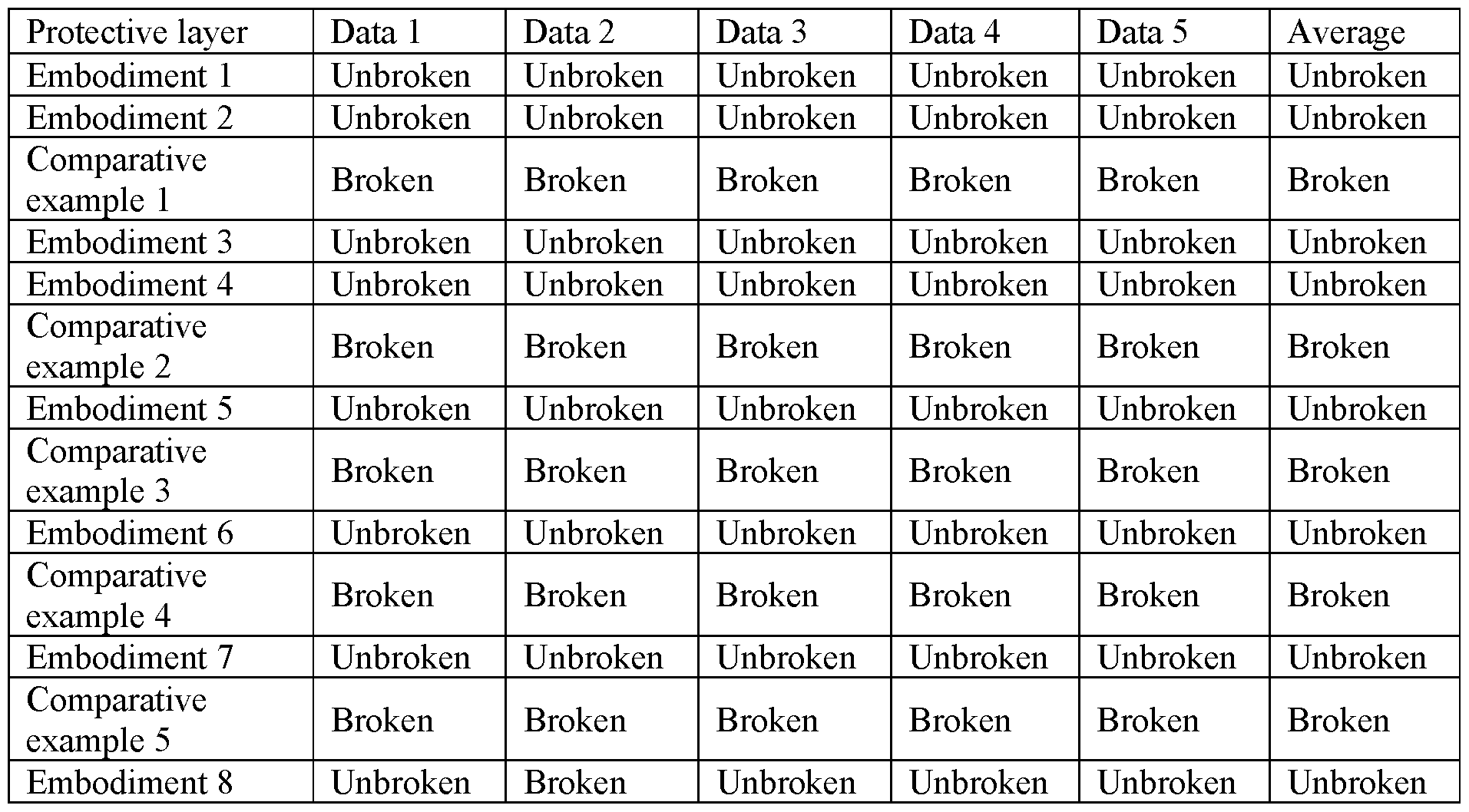
As can be seen from each embodiment above, when the Ra value of the Ra value of the second surface of the intermediary layer is within the range of 0.1 μιη to 7 μηι, except that individual samples in Embodiment 8 with the maximum Ra value break, all other
tensile removable adhesive tapes are removed smoothly without breaking. This indicates that the roughness within the above range can indeed effectively prevent the tensile removable adhesive tape from being broken. Moreover, if the Ra value is too large, it is unfavorable for preventing breakage of the tensile removable adhesive tape, and thus the Ra value of the second surface of the above intermediary layer is preferably less than 6 μπι, and more preferably less than 5 μιη.
Correspondingly, as can be seen from each above comparative example, when the Ra value of the second surface of each intermediary layer is less than 0.1 μπι, during the mechanical stretching, most of the tensile removable adhesive tapes are broken, while during manual stretching, all the tensile removable adhesive tapes are broken. However, in practical application, it is generally impossible to slowly remove the tensile removable adhesive tape by machinery, and thus results of manual stretching is more referable. This indicates that the traditional idea that the sliding resistance is smaller when the roughness is smaller is incorrect; and if the roughness of the second surface is too low, it also lead to the breakage of the tensile removable adhesive tapes.
It can be seen that no matter what material the intermediary layers are made of, what the original purpose is and whether the intermediary layers are polished, as long as the roughness of the second surface is within the above specific range, the effect of preventing the tensile removable adhesive tapes from being broken in the removing process can be achieved well; however, as long as the roughness exceeds this range, no matter whether the roughness is too large or too small, it easily leads to the breakage of the tensile removable adhesive tapes. This indicates that only by controlling the roughness of the second surfaces of the intermediary layers within this specific range according to the mode of the present invention can the effects of preventing the tensile removable adhesive tapes from being broken and improving reliability of the tensile removable adhesive tapes be achieved.
It can be understood that the embodiments are only exemplified embodiments adopted for describing the principle of the present invention; however, the present invention is not limited thereto. A person of ordinary skill in the art may make various variations and improvements without departing from the spirit and essence of the present invention, and these variations and improvements shall fall within the protection scope of the present invention.
Claims
1. An adhesive tape assembly used to bond to at least one substrate, wherein the adhesive tape assembly comprises:
a tensile removable adhesive tape, having bonding surfaces; and
an intermediary layer, covering at least part of the bonding surface of the tensile removable adhesive tape and has a first surface and a second surface opposite to each other; wherein the first surface is used to bond to the substrate;
the second surface is bonded to the bonding surface and at least part of the second surface is in direct contact with the bonding surface; and
the second surface has an Ra value between 0.1 μπι and 7 μπι.
2. The adhesive tape assembly according to Claim 1, wherein the second surface has an Ra value between 0.15 μπι and 6 μπι.
3. The adhesive tape assembly according to Claim 1, wherein the first surface is provided with a pressure-sensitive adhesive or a double-sided tape.
4. The adhesive tape assembly according to Claim 1, wherein the two sides of the tensile removable adhesive tape have the bonding surfaces, and the intermediary layer is bonded to only one of the bonding surfaces.
5. The adhesive tape assembly according to Claim 1, wherein at least one end of the tensile removable adhesive tape is not provided with the intermediary layer.
6. The adhesive tape assembly according to Claim 1, wherein in the width direction of the tensile removable adhesive tape, the size of the intermediary layer is greater than or equal to the width of the tensile removable adhesive tape.
7. The adhesive tape assembly according to Claim 1, wherein in the length direction of the tensile removable adhesive tape, the size of a portion of the second surface directly contacting the bonding surfaces is at least 5 mm.
8. The adhesive tape assembly according to Claim 1, wherein on the bonding surface where the intermediary layer is bonded, in the length direction of the tensile removable adhesive tape, the intermediary layer only covers part of the bonding surface;
or
on the bonding surface where the intermediary layer is bonded, in the length direction of the tensile removable adhesive tape, the intermediary layer completely covers the bonding surface.
9. The adhesive tape assembly according to Claim 1, further comprising:
a low-viscosity layer, being arranged between one end of the intermediary layer and the tensile removable adhesive tape, wherein at least one of both a bonding strength between the low-viscosity layer and the tensile removable adhesive tape and a bonding strength between the low-viscosity layer and the intermediary layer is smaller than that between the intermediary layer and the substrate.
10. The adhesive tape assembly according to Claim 9, wherein the bonding strength between the low-viscosity layer and the tensile removable adhesive tape is greater than that between the low-viscosity layer and the intermediary layer.
11. The adhesive tape assembly according to Claim 1, further comprising: a non-viscous layer, being arranged on at least one side of at least one end of the tensile removable adhesive tape, wherein a surface of the non-viscous layer far away from the tensile removable adhesive tape has no viscosity.
12. A bonding product, comprising:
a first substrate, having a first to-be-bonded surface;
a tensile removable adhesive tape, having bonding surfaces, wherein a portion of the tensile removable adhesive tape is bonded to the first to-be-bonded surface, and another portion of the tensile removable adhesive tape extends outside the first to-be-bonded surface; and
an intermediary layer, being at least arranged between an edge portion of the first to- be-bonded surface and the tensile removable adhesive tape and has a first surface and a
second surface opposite to each other, wherein at least part of the first surface is bonded to the edge portion of the first to-be-bonded surface; the second surface has an Ra value between 0.1 μηι and 7 μηι; and the second surface opposite to the first surface bonded to the edge portion of the first to-be-bonded surface is in direct contact with the bonding surface.
13. The bonding product according to Claim 12, wherein
the first substrate further comprises a side portion connected with the first to-be-bonded surface;
the tensile removable adhesive tape is at least partially bonded to the side portion; and
the intermediary layer is also arranged between the side portion and the tensile removable adhesive tape.
14. The bonding product according to Claim 12, further comprising a second substrate having a second to-be-bonded surface opposite to the first to-be-bonded surface; and the two sides of the tensile removable adhesive tape have the bonding surfaces, and a portion of the tensile removable adhesive tape is bonded between the first to-be-bonded surface and the second to-be-bonded surface.
15. The bonding product according to Claim 14, wherein
the bonding product is a mobile terminal;
the first substrate is a battery; and
the second substrate is a casing of the mobile terminal.
Applications Claiming Priority (2)
| Application Number | Priority Date | Filing Date | Title |
|---|---|---|---|
| CN201610031217.8 | 2016-01-18 | ||
| CN201610031217.8A CN105524570B (en) | 2016-01-18 | 2016-01-18 | Adhesive tape assembly, bonded product |
Publications (1)
| Publication Number | Publication Date |
|---|---|
| WO2017127293A1 true WO2017127293A1 (en) | 2017-07-27 |
Family
ID=55767105
Family Applications (1)
| Application Number | Title | Priority Date | Filing Date |
|---|---|---|---|
| PCT/US2017/013348 Ceased WO2017127293A1 (en) | 2016-01-18 | 2017-01-13 | Adhesive tape assembly and bonding product |
Country Status (2)
| Country | Link |
|---|---|
| CN (1) | CN105524570B (en) |
| WO (1) | WO2017127293A1 (en) |
Cited By (9)
| Publication number | Priority date | Publication date | Assignee | Title |
|---|---|---|---|---|
| CN107395814A (en) * | 2017-08-24 | 2017-11-24 | 广东欧珀移动通信有限公司 | Easy-to-draw glue component, housing unit and mobile terminal |
| EP3418341A1 (en) * | 2017-06-19 | 2018-12-26 | Guangdong OPPO Mobile Telecommunications Corp., Ltd. | Stretch release adhesive, housing assembly and electronic device |
| EP3428241A1 (en) * | 2017-07-14 | 2019-01-16 | Guangdong OPPO Mobile Telecommunications Corp., Ltd. | Stretch release adhesive, battery assembly and housing assembly |
| EP3447101A1 (en) * | 2017-08-24 | 2019-02-27 | Guangdong Oppo Mobile Telecommunications Corp., Ltd | Stretch releasing adhesive assembly, housing assembly and mobile terminal |
| EP3525260A1 (en) * | 2018-02-12 | 2019-08-14 | Beijing Xiaomi Mobile Software Co., Ltd. | Easy-to-remove member, battery assembly and electronic device |
| WO2020179464A1 (en) * | 2019-03-04 | 2020-09-10 | Dic株式会社 | Adhesive tape and object to be bonded |
| WO2020179465A1 (en) * | 2019-03-04 | 2020-09-10 | Dic株式会社 | Lamination film, adhesive tape, and adhesion body |
| WO2020195884A1 (en) * | 2019-03-26 | 2020-10-01 | Dic株式会社 | Bonded body, bonded body assembly method, and bonded body disassembly method |
| JP2024071407A (en) * | 2019-11-11 | 2024-05-24 | エルジー エナジー ソリューション リミテッド | Battery module, battery pack including same, and automobile |
Families Citing this family (3)
| Publication number | Priority date | Publication date | Assignee | Title |
|---|---|---|---|---|
| CN107195823B (en) * | 2017-06-19 | 2023-05-19 | 深圳市欢太科技有限公司 | Yi Lajiao, battery pack, housing pack and electronic device |
| CN107722855A (en) * | 2017-08-29 | 2018-02-23 | 张家港康得新光电材料有限公司 | Adhesive tape assembly, there is its battery compartment and mobile device |
| CN114380149B (en) * | 2022-01-27 | 2024-03-26 | 悦海自动化设备(威海)有限公司 | Automatic section tape winding equipment |
Citations (4)
| Publication number | Priority date | Publication date | Assignee | Title |
|---|---|---|---|---|
| US20020112823A1 (en) * | 2000-12-21 | 2002-08-22 | Achim Franck | Redetachable device |
| US20140123459A1 (en) * | 2012-11-02 | 2014-05-08 | Apple Inc. | Component removal systems for portable computers |
| WO2015135134A1 (en) * | 2014-03-11 | 2015-09-17 | 3M Innovative Properties Company | Stretch releasable adhesive article, usage and manufacturing the same |
| US20150315421A1 (en) * | 2014-04-30 | 2015-11-05 | Tesa Se | Auxiliary adhesive tape for a removable adhesive film |
Family Cites Families (5)
| Publication number | Priority date | Publication date | Assignee | Title |
|---|---|---|---|---|
| US6972141B1 (en) * | 1997-12-12 | 2005-12-06 | 3M Innovative Properties Company | Removable adhesive tape laminate and separable fastener |
| US6406781B1 (en) * | 1998-06-23 | 2002-06-18 | 3M Innovative Properties Company | Stretch release adhesive article with stabilizer |
| US7276272B2 (en) * | 2004-09-29 | 2007-10-02 | 3M Innovative Properties Company | Stretch releasing adhesive article for fragile surfaces |
| US7857130B2 (en) * | 2007-06-28 | 2010-12-28 | 3M Innovative Properties Company | Removable adhesive tape and pull tab film, and kits |
| US20150218425A1 (en) * | 2014-02-05 | 2015-08-06 | Apple Inc. | Stretch release conductive adhesive |
-
2016
- 2016-01-18 CN CN201610031217.8A patent/CN105524570B/en active Active
-
2017
- 2017-01-13 WO PCT/US2017/013348 patent/WO2017127293A1/en not_active Ceased
Patent Citations (4)
| Publication number | Priority date | Publication date | Assignee | Title |
|---|---|---|---|---|
| US20020112823A1 (en) * | 2000-12-21 | 2002-08-22 | Achim Franck | Redetachable device |
| US20140123459A1 (en) * | 2012-11-02 | 2014-05-08 | Apple Inc. | Component removal systems for portable computers |
| WO2015135134A1 (en) * | 2014-03-11 | 2015-09-17 | 3M Innovative Properties Company | Stretch releasable adhesive article, usage and manufacturing the same |
| US20150315421A1 (en) * | 2014-04-30 | 2015-11-05 | Tesa Se | Auxiliary adhesive tape for a removable adhesive film |
Cited By (20)
| Publication number | Priority date | Publication date | Assignee | Title |
|---|---|---|---|---|
| EP3418341A1 (en) * | 2017-06-19 | 2018-12-26 | Guangdong OPPO Mobile Telecommunications Corp., Ltd. | Stretch release adhesive, housing assembly and electronic device |
| US10532538B2 (en) | 2017-06-19 | 2020-01-14 | Guangdong Oppo Mobile Telecommunications Corp., Ltd. | Stretch release adhesive, housing assembly and electronic device |
| EP3428241A1 (en) * | 2017-07-14 | 2019-01-16 | Guangdong OPPO Mobile Telecommunications Corp., Ltd. | Stretch release adhesive, battery assembly and housing assembly |
| US10870258B2 (en) | 2017-08-24 | 2020-12-22 | Guangdong Oppo Mobile Telecommunications Corp., Ltd. | Stretch releasing adhesive assembly, housing assembly and mobile terminal |
| EP3447101A1 (en) * | 2017-08-24 | 2019-02-27 | Guangdong Oppo Mobile Telecommunications Corp., Ltd | Stretch releasing adhesive assembly, housing assembly and mobile terminal |
| CN107395814A (en) * | 2017-08-24 | 2017-11-24 | 广东欧珀移动通信有限公司 | Easy-to-draw glue component, housing unit and mobile terminal |
| EP3525260A1 (en) * | 2018-02-12 | 2019-08-14 | Beijing Xiaomi Mobile Software Co., Ltd. | Easy-to-remove member, battery assembly and electronic device |
| CN110148688A (en) * | 2018-02-12 | 2019-08-20 | 北京小米移动软件有限公司 | Detachable paper, battery components and electronic equipment |
| US10476057B2 (en) | 2018-02-12 | 2019-11-12 | Beijing Xiaomi Mobile Software Co., Ltd. | Easy-to-remove member, battery assembly and electronic device |
| JP2021167420A (en) * | 2019-03-04 | 2021-10-21 | Dic株式会社 | Adhesive tape and adhesive |
| WO2020179465A1 (en) * | 2019-03-04 | 2020-09-10 | Dic株式会社 | Lamination film, adhesive tape, and adhesion body |
| JPWO2020179465A1 (en) * | 2019-03-04 | 2021-03-25 | Dic株式会社 | Laminated films, adhesive tapes and adhesives |
| JPWO2020179464A1 (en) * | 2019-03-04 | 2021-09-13 | Dic株式会社 | Adhesive tape and adhesive |
| CN113508034A (en) * | 2019-03-04 | 2021-10-15 | Dic株式会社 | Adhesive tape and adhesive body |
| WO2020179464A1 (en) * | 2019-03-04 | 2020-09-10 | Dic株式会社 | Adhesive tape and object to be bonded |
| JP7338660B2 (en) | 2019-03-04 | 2023-09-05 | Dic株式会社 | Adhesive tapes and adhesives |
| CN113508034B (en) * | 2019-03-04 | 2023-12-05 | Dic株式会社 | Adhesive tapes and bonding bodies |
| WO2020195884A1 (en) * | 2019-03-26 | 2020-10-01 | Dic株式会社 | Bonded body, bonded body assembly method, and bonded body disassembly method |
| JP2024071407A (en) * | 2019-11-11 | 2024-05-24 | エルジー エナジー ソリューション リミテッド | Battery module, battery pack including same, and automobile |
| JP7769027B2 (en) | 2019-11-11 | 2025-11-12 | エルジー エナジー ソリューション リミテッド | Battery module, battery pack including same, and automobile |
Also Published As
| Publication number | Publication date |
|---|---|
| CN105524570A (en) | 2016-04-27 |
| CN105524570B (en) | 2018-10-12 |
Similar Documents
| Publication | Publication Date | Title |
|---|---|---|
| WO2017127293A1 (en) | Adhesive tape assembly and bonding product | |
| US20200235771A1 (en) | Protective covers for electronic devices | |
| US10421885B2 (en) | Dry apply protective systems | |
| US9248634B2 (en) | Protective adhesive film, method of adhering protective adhesive film to a device, and device comprising protective adhesive film | |
| KR102214626B1 (en) | Double-sided adhesive sheet for image display device, double-sided adhesive sheet with release film for image display device and image display device using same | |
| CN102896876A (en) | Film tearing machine and film tearing method | |
| CN209890544U (en) | Protection film, screen assembly | |
| KR20130018190A (en) | Adhesive film | |
| JP6405045B2 (en) | Film pasting method | |
| WO2014005144A1 (en) | Protective covering for electronic devices having improved elasticity and impact resistance properties | |
| KR20210055661A (en) | Antistatic surface-protective film | |
| JP2001064607A (en) | Surface protection film | |
| US10046543B2 (en) | Laminated film and film attachment method | |
| TW202016577A (en) | Optical laminate with cover glass and image display device with cover glass | |
| KR101053235B1 (en) | Protective film set and manufacturing method | |
| CN211847785U (en) | Protection film, protection film subassembly, display screen subassembly and terminal | |
| JP7827104B2 (en) | Method for manufacturing a roll body and roll body | |
| CN106062111A (en) | Adhesive scattering prevention sheet | |
| JP7281800B2 (en) | Adhesive tape for screen protection and screen protection material | |
| TW201431698A (en) | Protective film structure and method of application thereof | |
| KR102753964B1 (en) | Optical laminate, optical laminate with cover glass attached, and method for manufacturing the same, and image display device with cover glass attached | |
| JP2001031924A (en) | Surface protection film | |
| KR20190000198U (en) | Lcd protection film structure for mobile terminal | |
| KR20210038693A (en) | Optical laminate with cover glass and image display device with cover glass | |
| KR101236442B1 (en) | Film structure for protecting surface |
Legal Events
| Date | Code | Title | Description |
|---|---|---|---|
| 121 | Ep: the epo has been informed by wipo that ep was designated in this application |
Ref document number: 17707694 Country of ref document: EP Kind code of ref document: A1 |
|
| NENP | Non-entry into the national phase |
Ref country code: DE |
|
| 122 | Ep: pct application non-entry in european phase |
Ref document number: 17707694 Country of ref document: EP Kind code of ref document: A1 |