WO2017126679A1 - 照明器及び栽培設備 - Google Patents
照明器及び栽培設備 Download PDFInfo
- Publication number
- WO2017126679A1 WO2017126679A1 PCT/JP2017/001983 JP2017001983W WO2017126679A1 WO 2017126679 A1 WO2017126679 A1 WO 2017126679A1 JP 2017001983 W JP2017001983 W JP 2017001983W WO 2017126679 A1 WO2017126679 A1 WO 2017126679A1
- Authority
- WO
- WIPO (PCT)
- Prior art keywords
- wavelength component
- ppf
- illuminator
- less
- wavelength
- Prior art date
- Legal status (The legal status is an assumption and is not a legal conclusion. Google has not performed a legal analysis and makes no representation as to the accuracy of the status listed.)
- Ceased
Links
Images





Classifications
-
- A—HUMAN NECESSITIES
- A01—AGRICULTURE; FORESTRY; ANIMAL HUSBANDRY; HUNTING; TRAPPING; FISHING
- A01G—HORTICULTURE; CULTIVATION OF VEGETABLES, FLOWERS, RICE, FRUIT, VINES, HOPS OR SEAWEED; FORESTRY; WATERING
- A01G7/00—Botany in general
-
- H—ELECTRICITY
- H10—SEMICONDUCTOR DEVICES; ELECTRIC SOLID-STATE DEVICES NOT OTHERWISE PROVIDED FOR
- H10H—INORGANIC LIGHT-EMITTING SEMICONDUCTOR DEVICES HAVING POTENTIAL BARRIERS
- H10H20/00—Individual inorganic light-emitting semiconductor devices having potential barriers, e.g. light-emitting diodes [LED]
- H10H20/80—Constructional details
- H10H20/85—Packages
- H10H20/851—Wavelength conversion means
Definitions
- Embodiment of this invention is related with an illuminator and cultivation equipment.
- a remote monitoring system for grasping the cultivation status, a sterilization system for disinfecting packing materials, and an air conditioning system for realizing an environment of uniform temperature and humidity are introduced.
- lighting devices such as fluorescent lamps and LEDs are installed for plant cultivation.
- An object of the present invention is to provide an illuminator and a cultivation facility that are excellent in adjusting nutrient components of a growing body such as a plant.
- the illuminator of the embodiment includes a first wavelength component having a light intensity of 600 nm to 700 nm, a second wavelength component having a light intensity of 500 nm to less than 600 nm, and a third wavelength component having a light intensity of 400 nm to less than 500 nm. It is a growing illuminator that emits an emission spectrum including a wavelength component.
- the content ratio (PPF-R) of the photosynthesis effective photon flux of the first wavelength component to the photosynthesis effective photon flux of the three wavelength components of the first, second, and third wavelength components is 20%.
- the photosynthesis effective photon flux content of the second wavelength component (PPF-G) is 25% or more and 35% or less, and the photosynthesis effective photon flux content of the third wavelength component (PPF-G) B) satisfies 40% to 50%.
- FIG. 1 is a diagram illustrating an example of a schematic configuration of a hydroponic cultivation system (cultivation equipment) common to the first and second embodiments.
- the hydroponics system 1 has the cultivation bed 11 arrange
- the cultivation shelf 10 is provided in three stages, but the number of cultivation shelves 10 is arbitrary.
- a plurality of seedling receiving cups 14 for holding plants to be cultivated are arranged on top of the cultivation basket 13 that stores the culture solution 12.
- the seedling receiving cup 14 is held on top of the cultivation basket 13 via a flat cultivation tray 15 formed of foamable resin or the like.
- the seedling receiving cup 14 and the cultivation tray 15 constitute a growing body holding unit.
- the seedling receiving cup 14 is formed into a cup shape by, for example, a resin material, and a circular hole 14a is formed on the bottom surface.
- a medium for growing the growing body 5 such as plant seedlings and seeds is accommodated together with the growing body 5.
- a fibrous material excellent in air permeability and water absorption, a block-like porous resin, a granular material, or the like can be used.
- the hole 14 a on the bottom surface of the seedling receiving cup 14 is used to absorb the culture solution 12 in the cultivation basket 13 into the culture medium and to extend the root 5 a of the growing body 5 in the seedling receiving cup 14 into the culture solution 12. .
- the culture solution 12 is supplied to the inside through the water supply unit 16, and the culture solution 12 exceeding a predetermined water level is discharged to the outside from the drain port 17.
- the water supply part 16 is arrange
- the drain port 17 is formed in the bottom face of the other end side of the cultivation basket 13 in the longitudinal direction.
- the drainage port 17 is formed in a cylindrical drainage cylinder 18 that protrudes downward from the bottom wall of the cultivation basket 13.
- the positions of the drain ports 17 (drain tubes 18) of the cultivation rods 13 arranged in the vertical direction are set to be staggered in the longitudinal direction.
- a connecting pipe 19 is connected to the drain cylinder 18.
- connection pipe 19 connected to the drain cylinder 18 of the upper cultivation basket 13 is connected to the water supply unit 16 of the suspended cultivation basket 13.
- a connecting pipe 19 connected to the drain tube 18 of the middle cultivation basket 13 is connected to the water supply unit 16 of the lower cultivation basket 13.
- the connection pipe 19 connected to the drain cylinder 18 of the lower cultivation basket 13 is connected to the culture medium tank 21.
- a foreign matter removal net that captures foreign matters such as dust flowing in with the culture solution is installed inside the culture solution tank 21.
- the culture tank 21 is connected to the water supply unit 16 of the upper cultivation rod 13 via the circulation pump 20.
- a cylindrical water level adjusting cylinder 22 is detachably inserted into the drain port 17 of each cultivation basket 13.
- the water level adjusting cylinder 22 has an opening 22 a communicating with the upper space in the cultivation basket 13.
- the water level adjusting cylinder 22 discharges the culture solution 12 exceeding the predetermined water level in the cultivation basket 13 to the drain port 17 through the opening 22a.
- an illuminating device 30 for nurturing a growing body of the LED light source cylinder is installed above the seedling receiving cup 14 of each cultivation shelf 10.
- the illuminating device 30 includes a reflector (reflecting material) 30a, an illuminator 31 (or illuminators 32 and 33), and the like.
- the lighting device 30 will be described in detail later.
- FIG. 2 is a diagram illustrating an example of a schematic configuration of the illumination device 30 according to the first embodiment.
- the illumination device 30 includes a plurality of illuminators 31.
- the illuminator 31 is an illuminator having an emission spectrum having RGB wavelength components, and includes a plurality of LED (Light Emitting Diode) lamps 41 arranged in a straight line.
- LED Light Emitting Diode
- 1st Embodiment demonstrates the case where several LED lamp 41 is arrange
- FIG. 3 is a cross-sectional view showing an example of a schematic configuration of the LED lamp 41.
- the LED lamp 41 has an LED chip 412 as a light emitting element.
- a blue light emitting type LED chip is used as the LED chip 412.
- This LED chip 412 is mounted on a circuit pattern 415 provided on a substrate 413 via an electrical insulating layer 414.
- the substrate 413 is made of a flat plate made of aluminum (Al), nickel (Ni), glass epoxy or the like having heat dissipation and rigidity.
- the circuit pattern 415 is made of an alloy of copper (Cu) and nickel (Ni), gold (Au), or the like, and has circuit patterns 415 on the anode side and the cathode side.
- the LED chip 412 is placed on one (for example, the anode side) circuit pattern 415, the bottom electrode is electrically connected, and the top surface electrode is electrically connected to the other (for example, the cathode side) circuit pattern 415 by the bonding wire 416. It is connected to the.
- a frame 418 is provided on the substrate 413 to form a truncated cone-shaped recess 417 that gradually increases in diameter upward, and the LED chip 412 is disposed in the recess 417.
- the frame 418 is made of, for example, polybutylene terephthalate (PBT), polyphthalamide (PPA), polycarbonate (PC), etc., and the recess 417 has a truncated cone shape with a depth of 0.5 to 1.0 mm, for example. Is formed.
- a phosphor-containing resin layer 419 mainly containing a transparent resin (thermosetting resin) and containing two or more kinds of phosphors (arbitrary phosphors) having different main wavelengths.
- the LED chip 412 is sealed in the recess 417 by the phosphor-containing resin layer 419.
- the phosphor-containing resin layer 419 is prepared by using a phosphor-containing resin (phosphor dispersion liquid) in which two or more kinds of phosphors are mixed and dispersed in a liquid transparent resin (thermosetting resin) and an injection device such as a dispenser. It is formed by injecting into the concave portion 417 in which the LED chip 412 is arranged and heat-curing.
- a phosphor-containing resin phosphor dispersion liquid
- a liquid transparent resin thermosetting resin
- an injection device such as a dispenser. It is formed by injecting into the concave portion 417 in which the LED chip 412 is arranged and heat-curing.
- the transparent resin include a silicone resin and an epoxy resin.
- the use of a liquid silicone resin is preferred, and the use of a silicone resin having a viscosity of 1 to 70 Pa ⁇ s at 25 ° C. is particularly preferred from the viewpoint of ease of injection.
- the injection amount of the phosphor-containing resin in which two or more kinds of the phosphors are mixed and dispersed is approximately 5 to 10 mg.
- the upper surface of the phosphor-containing resin layer 419 is formed to be substantially flush with the upper end of the concave portion 417.
- the present invention is not limited to this.
- the main wavelengths of the two or more kinds of phosphors to be contained in the transparent resin are not particularly limited, and can be appropriately selected according to the emission color of the target LED lamp 411.
- a yellow phosphor that is excited by blue light emitted from the blue light emitting type LED chip 412 and emits light between yellow light and orange light is used. Further, at least one of a green or yellow-green phosphor having a dominant wavelength of 500 to 560 nm and a red phosphor having a dominant wavelength of 620 to 650 nm can be used together with the yellow phosphor.
- a yellow phosphor that emits light between yellow light and orange light when excited by blue light
- RE is selected from Y, Gd, and La
- YAG phosphor such as AE2SiO4: Eu phosphor
- AE represents an alkaline earth element such as Sr, Ba, Ca, etc.
- Sr3SiO5 Eu2 + phosphor
- silicate phosphors, sialon phosphors for example, CaxSiyAlzON: Eu2 +
- Ca3Sc2O4 Ce phosphors, and the like, which are selected from these.
- green or yellow-green phosphor examples include YAG phosphors such as RE3 (Al, Ga) 5O12: Ce phosphors, silicate phosphors such as AE2SiO4: Eu phosphors and Ca3Sc2Si3O12: Ce phosphors, and sialon phosphors.
- Body for example, CaxSiyAlzON: Eu2 +
- Ca3Sc2O4 Ce phosphor, and the like, which are selected from these.
- an oxysulfide phosphor such as a La2O2S: Eu phosphor, a nitride-based phosphor (for example, AE2Si5N8: Eu2 +, CaAlSiN3: Eu2 +), or the like is used, but is not particularly limited.
- the applied electric energy is converted by the LED chip 412 into blue light having a dominant wavelength of 420 to 480 nm (for example, 460 nm) and emitted, and the emitted blue light is converted into a phosphor.
- Two or more kinds of phosphors contained in the containing resin layer 419 are converted into light having a longer wavelength.
- white light which is a color based on the blue light emitted from the LED chip 412 and the emission colors of these phosphors, is emitted from the LED lamp 41.
- the lighting device 30 has the following characteristic (1).
- the illumination device 30 has a first wavelength component (red light: R) having a light intensity at 600 to 700 nm (600 nm to 700 nm or less) and a first wavelength component having a light intensity at 500 to 600 nm (for example, 500 nm to less than 600 nm).
- An emission spectrum including two wavelength components (green light: G) and a third wavelength component (blue light: B) having a light intensity at 400 to 500 nm (for example, 400 nm to less than 500 nm) is emitted.
- the lighting device 30 includes the photosynthesis effective photon flux of the first wavelength component with respect to the photosynthesis effective photon flux (PPF: Photosynthetic Photon Flux) of the three wavelength components of the first, second, and third wavelength components.
- the content ratio (PPF-B) of the photosynthesis effective photon flux of the third wavelength component satisfies the third condition of 40% or more and 50% or less (the illumination device 30 has the PPF-R shown in FIGS. 6 and 7). , Meet the requirements of PPF-B).
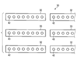
- FIG. 4 is a diagram illustrating an example of a schematic configuration of the illumination device 30 according to the second embodiment.
- the illuminating device 30 includes a plurality of illuminators (illuminators 32 and 33).
- the illuminator 32 is an illuminator having a white emission spectrum having RGB wavelength components, and includes a plurality of white LED lamps 42 arranged in a straight line.
- the basic configuration of the illuminator 32 and the LED lamp 42 is the same as that of the illuminator 31 and the LED lamp 41.
- the illuminator 33 is, for example, an LED lamp configured by a white LED 43 having an emission spectrum different from that of the illuminator 32.
- the lighting device 30 according to the second embodiment has the following characteristics (1) by controlling the outputs of the illuminators 32 and 33.
- the illumination device 30 has a first wavelength component (red light: R) having a light intensity at 600 to 700 nm (600 nm to 700 nm or less) and a first wavelength component having a light intensity at 500 to 600 nm (for example, 500 nm to less than 600 nm).
- An emission spectrum including two wavelength components (green light: G) and a third wavelength component (blue light: B) having a light intensity at 400 to 500 nm (for example, 400 nm to less than 500 nm) is emitted.
- the lighting device 30 includes the photosynthesis effective photon flux of the first wavelength component with respect to the photosynthesis effective photon flux (PPF: Photosynthetic Photon Flux) of the three wavelength components of the first, second, and third wavelength components.
- the content ratio (PPF-B) of the photosynthesis effective photon flux of the third wavelength component satisfies the third condition of 40% or more and 50% or less (the illumination device 30 has the PPF-R shown in FIGS. 6 and 7). , Meet the requirements of PPF-B).
- the white LED lamp is not limited to the one described above.
- an LED lamp that realizes white light emission using three LED chips that emit light in blue, green, and red colors. May be applied, or an LED lamp that realizes white light emission may be applied by combining an LED chip that emits ultraviolet light and a three-color mixed phosphor that emits blue, green, and red light. .
- FIG. 5 is a block diagram showing an example of a schematic configuration of a hydroponic cultivation system common to the first and second embodiments.
- the hydroponics system includes an input unit 51, a storage unit 52, an information processing unit 53, a lighting control unit 54, and a lighting device 30.
- the input unit 51 is configured by a keyboard, a display, and the like, and corresponds to the input operation of the user, for example, of the desired taste, nutrient content, sugar content, nitrate value, etc. Enter at least one piece of information.
- the storage unit 52 stores conversion data.
- the information processing unit 53 generates and outputs illumination control information based on the conversion data stored in the storage unit 52 and information input from the input unit 51.
- the illumination control unit 54 controls the illumination device 30 based on the illumination control information. For example, the illumination control unit 54 independently controls the output of each illuminator constituting the illumination device 30.
- the illumination control unit 54 controls the output balance, intensity, output days (cultivation days), and the like of the plurality of illuminators 31 that configure the illumination device 30 based on the illumination control information.
- the illumination control part 54 controls the output balance, intensity
- the average value of the value of the photosynthesis effective photon flux density is 150 umol m-2 s-1 or more.
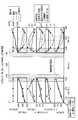
- FIG. 6 is a diagram showing an example of the relationship between vitamins B1, B2, B6, E, K and PPF-R and PPF-B.
- the lighting device 30 includes a first condition in which the PPF-R content is 20% to 30%, a second condition in which the PPF-G content is 25% to 35%,
- the third condition in which the content of PPF-B was 40% or more and 50% or less was satisfied, and in this case, good results were obtained for some nutritional components in the breeding body. For example, good results were obtained for vitamin B2, vitamin B6, tocopherol, and vitamin K as the content of PPF-B increased.
- the favorable result was obtained about vitamin B2, vitamin B6, tocopherol, and vitamin K according to the reduction
- the content of PPF-G depends on the content of PPF-R and PPF-B, and the effect of the content of PPF-G on the increase or decrease of nutrients is small. Description of rate is omitted.
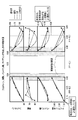
- FIG. 7 is a diagram showing an example of the relationship between ferroquinone, folic acid, pantothenic acid, niacin and PPF-R and PPF-B.
- the lighting device 30 includes a first condition in which the PPF-R content is 20% to 30%, a second condition in which the PPF-G content is 25% to 35%,
- the third condition in which the content of PPF-B was 40% or more and 50% or less was satisfied, and in this case, good results were obtained for some nutritional components in the breeding body. For example, good results were obtained for ferroquinone, folic acid, pantothenic acid, and niacin as the PPF-B content increased.
- FIG. 8 is a diagram showing an example of the content of vitamin C and the BR ratio of light. As shown in FIG. 8, the lighting device 30 has a PPF-R content of 30% or less and a PPF-B content of 40% or more. Become more.
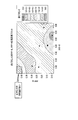
- FIG. 9 is a diagram showing an example of the content of ⁇ -carotene and the BR ratio of light.
- the lighting device 30 has a PPF-R content of 30% or less and a PPF-B content of 36% or more. Become more.
- the content of PPF-R is around 25% and the content of PPF-B is around 45%, the content of nutrient components (such as ⁇ -carotene) in the growing body increases.
- FIG. 10 is a diagram showing an example of taste analysis data of cosmetics grown by FL (Fluorescent® Lamp) illumination.
- examples of taste analysis data of cosmetus cultivated by white FL (Fluorescent ⁇ Lamp) illumination, white FL illumination and blue monochromatic LED illumination, and white FL illumination and red monochromatic LED illumination FIG. 10 for example, when blue light is strong, salty taste (taste) is strong, and when red light is strong, umami (prior taste) and umami richness (aftertaste) are suppressed. The longer the cultivation days, the higher the sugar content. By adjusting the spectrum of the light irradiated to the growing body from the illuminating device 30, the taste of the harvested growing body can be adjusted.
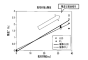
- FIG. 11 is a diagram showing an example of the relationship between the number of cultivation days and the sugar content. As shown in FIG. 11, the sugar content tends to increase according to the number of cultivation days.
- the LED in FIG. 11 shows an example of the relationship between the number of cultivation days by the lighting device 30 and the sugar content.
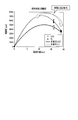
- FIG. 12 is a figure which shows an example of the relationship between the cultivation days and nitric acid. As shown in FIG. 12, the nitric acid value increases until the 20th day of cultivation, but then tends to decrease. Thus, the nutrients (sugar content, nitric acid value, etc.) of the harvested growing bodies can be controlled (adjusted) by adjusting the cultivation days.
- the LEDs in FIG. 12 show an example of the relationship between the number of cultivation days by the lighting device 30 and the nitric acid value.
- the storage unit 52 of the hydroponic cultivation system of the first and second embodiments stores taste analysis data shown in FIG. 10, sugar content change data shown in FIG. 11, nitrate value change data shown in FIG. 12, and the like.
- the input unit 51 inputs at least one information of a desired taste, nutrient content, sugar content, nitric acid value, and the like of the growing body to be cultivated.
- the information processing unit 53 generates and outputs illumination control information based on the data stored in the storage unit 52 and information input from the input unit 51.
- the illumination control unit 54 controls the illumination device 30 based on the illumination control information.
- breeding bodies such as the taste which the breeding body to grow, content of nutrients, sugar content, and a nitric acid value, can be grown.
- the illuminating device 30 can be configured to have at least the characteristic (1). Further, by providing the lighting device 30 with a reflector (reflecting material), a desired composite spectrum ((1) above) can be emitted.
- the hydroponic cultivation system described above it is possible to adjust the nutritional / taste components by adjusting the RGB ratio in the spectrum of light irradiated to the growing body such as a plant.
- the growing body such as a plant.
- enhancement of nutrients vitamin A, B2, C, E, K, ferroquinone, folic acid, pantothenic acid, niacin, etc.
Landscapes
- Life Sciences & Earth Sciences (AREA)
- Biodiversity & Conservation Biology (AREA)
- Botany (AREA)
- Ecology (AREA)
- Forests & Forestry (AREA)
- Environmental Sciences (AREA)
- Cultivation Of Plants (AREA)
- Hydroponics (AREA)
- Led Device Packages (AREA)
Abstract
植物等の育成体の栄養成分の調整に優れた照明器を提供すること。 実施形態の照明器は、600nm以上700nm以下に光強度を有する第1の波長成分、500nm以上600nm未満に光強度を有する第2の波長成分、及び400nm以上500nm未満に光強度を有する第3の波長成分を含む発光スペクトルを放出する育成用の照明器である。前記照明器は、前記第1、第2、及び第3の波長成分の3波長成分の光合成有効光子束に対する前記第1の波長成分の光合成有効光子束の含有率(PPF-R)が20%以上30%以下、前記第2の波長成分の光合成有効光子束の含有率(PPF-G)が25%以上35%以下、及び前記第3の波長成分の光合成有効光子束の含有率(PPF-B)が40%以上50%以下を満たす。
Description
本発明の実施形態は、照明器及び栽培設備に関する。
近年、屋内施設における野菜等の栽培に関する研究開発が盛んになっている。屋内施設は、菌の侵入を制限したクリーンルームとする。これにより、雑菌の少ない野菜等を生産することが可能となる。このようなクリーンルームで生産される野菜等は、雑菌による傷みが少なく長期保存が可能であり、高い鮮度が長期的に求められるカット野菜やサラダ用に適する。
屋内施設における野菜等の生産には、栽培状況を把握するための遠隔監視システム、梱包材などを消毒する除菌システム、及び均一な温度・湿度の環境を実現する空調システム等が導入される。加えて、植物育成向けに蛍光灯やLED等の照明装置が設置される。
上記の通り、屋内施設における野菜等の栽培に関する研究開発が盛んになっており、例えば植物等の育成体の栄養成分を調整する照明技術が望まれている。
本発明の目的は、植物等の育成体の栄養成分の調整に優れた照明器及び栽培設備を提供することである。
実施形態の照明器は、600nm以上700nm以下に光強度を有する第1の波長成分、500nm以上600nm未満に光強度を有する第2の波長成分、及び400nm以上500nm未満に光強度を有する第3の波長成分を含む発光スペクトルを放出する育成用の照明器である。前記照明器は、前記第1、第2、及び第3の波長成分の3波長成分の光合成有効光子束に対する前記第1の波長成分の光合成有効光子束の含有率(PPF-R)が20%以上30%以下、前記第2の波長成分の光合成有効光子束の含有率(PPF-G)が25%以上35%以下、及び前記第3の波長成分の光合成有効光子束の含有率(PPF-B)が40%以上50%以下を満たす。
図1は、第1及び第2の実施形態に共通の水耕栽培システム(栽培設備)の概略構成の一例を示す図である。図1に示すように、水耕栽培システム1は、上下方向に複数段設けられた栽培棚10上に、栽培ベッド11が配置されている。本実施形態においては、栽培棚10は三段設けられているが、栽培棚10の段数は任意である。栽培ベッド11は、培養液12を貯留する栽培桶13の上部に栽培する植物を保持する複数の苗受けカップ14が配置されている。苗受けカップ14は、発泡性樹脂等によって形成された平板状の栽培トレー15を介して栽培桶13の上部に保持されている。本実施形態においては、苗受けカップ14と栽培トレー15が生育体保持部を構成している。
苗受けカップ14は、例えば、樹脂材料等によってカップ状に形成され、底面には円形状の孔14aが形成されている。苗受けカップ14内には、植物の苗や種子等の生育体5を育成するための培地が生育体5とともに収容されている。培地としては、通気性と吸水性に優れた繊維質素材やブロック状の多孔質樹脂、粒状物等を採用することができる。苗受けカップ14の底面の孔14aは、栽培桶13内の培養液12を培地に吸水させるとともに、苗受けカップ14内の生育体5の根5aを培養液12内に伸ばすために利用される。なお、苗受けカップ14からは、培地に培養液12を吸わせるために吸水布を垂らすようにしてもよい。
栽培桶13は、給水部16を通して内部に培養液12が供給され、所定水位を超えた培養液12が排水口17から外部に排出される。給水部16は、栽培桶13の長手方向の一端側の上部に配置されている。
排水口17は、栽培桶13の長手方向の他端側の底面に形成されている。排水口17は、栽培桶13の底壁から下方に突出して形成された円筒状の排水筒18に形成されている。上下方向に配列される各栽培桶13の排水口17(排水筒18)の位置は、長手方向で互い違いとなるように設定されている。排水筒18には接続管19が接続されている。
上段の栽培桶13の排水筒18に接続された接続管19は、中断の栽培桶13の給水部16に接続されている。中段の栽培桶13の排水筒18に接続された接続管19は、下段の栽培桶13の給水部16に接続されている。また、下段の栽培桶13の排水筒18に接続された接続管19は、培養液タンク21に接続されている。なお、培養液タンク21の内部には、培養液とともに流れ込んだゴミ等の異物を捕捉する異物除去網が設置されている。また、培養液タンク21には、循環ポンプ20を介して上段の栽培桶13の給水部16が接続されている。
各栽培桶13の排水口17には、円筒状の水位調整筒22が着脱可能に嵌入されている。水位調整筒22は、栽培桶13内の上部空間に連通する開口部22aを有している。水位調整筒22は、栽培桶13内で所定水位を超えた培養液12を、開口部22aを通して排水口17に排出する。
また、各栽培棚10の苗受けカップ14の上方位置には、LED光源筒の育成体の育成用の照明装置30が設置されている。この照明装置30は、反射板(反射材)30a、及び照明器31(又は照明器32及び33)等を備える。この照明装置30については後に詳しく説明する。
図2は、第1の実施形態に係る照明装置30の概略構成の一例を示す図である。図2に示すように、照明装置30は、複数の照明器31を備える。照明器31は、RGBの各波長成分を有する発光スペクトルを有する照明器であり、直線状に配置された複数のLED(Light Emitting Diode)ランプ41を備える。なお、第1の実施形態では、複数のLEDランプ41が直線状(一列)に配置されるケースについて説明するが、複数のLEDランプ41が2以上の直線状(複数列)に配置されてもよい。
図3は、LEDランプ41の概略構成の一例を示す断面図である。図3に示すように、LEDランプ41は、発光素子としてLEDチップ412を有している。LEDチップ412としては、例えば青色発光タイプのLEDチップが用いられている。このLEDチップ412は、基板413上に電気絶縁層414を介して設けられた回路パターン415上に搭載されている。
基板413は、放熱性と剛性を有するアルミニウム(Al)、ニッケル(Ni)、ガラスエポキシ等の平板から成る。また、回路パターン415は、銅(Cu)とニッケル(Ni)の合金、金(Au)等により構成され、陽極側と陰極側の回路パターン415を有している。LEDチップ412は、一方(例えば陽極側)の回路パターン415上に載置されて底面電極が電気的に接続され、上面電極が他方(例えば陰極側)の回路パターン415にボンディングワイヤ416により電気的に接続されている。基板413上には、上方に向けて徐々に拡径する円錐台状の凹部417を形成するフレーム418が設けられており、LEDチップ412はこの凹部417内に配置されている。フレーム418は、例えばポリブチレンテレフタレート(PBT)、ポリフタルアミド(PPA)、ポリカーボネート(PC)等により形成されており、凹部417は、例えば深さが0.5~1.0mmの円錐台状に形成されている。
LEDチップ412が配置された凹部417内には、透明樹脂(熱硬化性樹脂)を主体とし、主波長の異なる2種類以上の蛍光体(任意の蛍光体)を含有する蛍光体含有樹脂層419が設けられており、LEDチップ412はこの蛍光体含有樹脂層419により凹部417内に封止されている。
蛍光体含有樹脂層419は、液状の透明樹脂(熱硬化性樹脂)に2種類以上の前記蛍光体を混合・分散させた蛍光体含有樹脂(蛍光体分散液)を、ディスペンサなどの注入装置を用いてLEDチップ412が配置された凹部417内に注入し、加熱硬化させることにより形成されている。透明樹脂としては、シリコーン樹脂、エポキシ樹脂等が挙げられる。液状のシリコーン樹脂の使用が好ましく、注入の容易さの観点から、25℃における粘度が1~70Pa・sのシリコーン樹脂の使用が特に好ましい。2種類以上の前記蛍光体が混合・分散された蛍光体含有樹脂の注入量は、ほぼ5~10mgである。なお、図面では、蛍光体含有樹脂層419の上面が凹部417の上端とほぼ面一に形成されているが、特にこれに限定されるものではない。透明樹脂に含有させる2種類以上の蛍光体の主波長は、特に限定されるものではなく、目的とするLEDランプ411の発光色などに応じて適宜選択することができる。
蛍光体としては、例えば、青色発光タイプのLEDチップ412から発光される青色光により励起されて黄色光から橙色光間の光を発光する黄色系蛍光体が用いられる。また、主波長が500~560nmの緑色あるいは黄緑色蛍光体と、主波長が620~650nmの赤色蛍光体の少なくとも一方を前記黄色系蛍光体とともに用いることができる。ここで、青色光により励起されて黄色光から橙色光間の光を発光する黄色系蛍光体としては、例えばRE3(Al,Ga)5O12:Ce蛍光体(REはY、GdおよびLaから選ばれる少なくとも1種を示す。以下同じ。)等のYAG系蛍光体、AE2SiO4:Eu蛍光体(AEは、Sr、Ba、Caなどのアルカリ土類元素を示す。以下同じ。)やSr3SiO5:Eu2+蛍光体等のケイ酸塩(シリケート)蛍光体、サイアロン系蛍光体(例えば、CaxSiyAlzON:Eu2+)、およびCa3Sc2O4:Ce蛍光体等があり、これらの中から選択される。緑色あるいは黄緑色蛍光体としては、例えばRE3(Al,Ga)5O12:Ce蛍光体等のYAG系蛍光体、AE2SiO4:Eu蛍光体やCa3Sc2Si3O12:Ce蛍光体等のケイ酸塩蛍光体、サイアロン系蛍光体(例えば、CaxSiyAlzON:Eu2+)、およびCa3Sc2O4:Ce蛍光体等があり、これらの中から選択される。赤色蛍光体としては、La2O2S:Eu蛍光体のような酸硫化物蛍光体、窒化物系蛍光体(例えば、AE2Si5N8:Eu2+やCaAlSiN3:Eu2+)等が用いられるが、特に限定されるものではない。
このように構成されるLEDランプ41では、印加された電気エネルギーがLEDチップ412で主波長が420~480nm(例えば460nm)の青色光に変換されて放射され、放射された青色光は、蛍光体含有樹脂層419中に含有された2種類以上の蛍光体で、より長波長の光に変換される。そして、LEDチップ412から放射される青色光とこれらの蛍光体の発光色とに基づく色である白色光がLEDランプ41から放出される。
例えば、LEDランプ41の蛍光体含有樹脂層419の2種類以上の蛍光体の含有量及び混合比等を調整することにより、照明装置30は、以下(1)の特性を有する。
(1)照明装置30は、600-700nm(600nm以上700nm以下)に光強度を有する第1の波長成分(赤色光:R)、500-600nm(例えば500nm以上600nm未満)に光強度を有する第2の波長成分(緑色光:G)、及び400-500nm(例えば400nm以上500nm未満)に光強度を有する第3の波長成分(青色光:B)を含む発光スペクトルを放出する。さらに、照明装置30は、前記第1、第2、及び第3の波長成分の3波長成分の光合成有効光子束(PPF:Photosynthetic Photon Flux)に対する前記第1の波長成分の光合成有効光子束の含有率(PPF-R)が20%以上30%以下の第1の条件、前記第2の波長成分の光合成有効光子束の含有率(PPF-G)が25%以上35%以下の第2の条件、及び前記第3の波長成分の光合成有効光子束の含有率(PPF-B)が40%以上50%以下の第3の条件を満たす(照明装置30は図6及び図7に示すPPF-R、PPF-Bの条件を満たす)。
図4は、第2の実施形態に係る照明装置30の概略構成の一例を示す図である。図4に示すように、照明装置30は、複数の照明器(照明器32及び33)を備える。照明器32は、RGBの各波長成分を有する白色系の発光スペクトルを有する照明器であり、一直線状に配置された複数の白色系LEDランプ42を備える。なお、照明器32及びLEDランプ42の基本的な構成は照明器31及びLEDランプ41と同様である。照明器33は、例えば、単色青色系のLED43(ピーク発光波長λp=400nm以上500nm未満)により構成されるLEDランプである。或いは、照明器33は、例えば、単色赤色系のLED43(ピーク発光波長λp=600nm以上700nm以下)により構成されるLEDランプである。或いは、照明器33は、例えば、照明器32とは発光スペクトルが異なる白色系のLED43により構成されるLEDランプである。
第2の実施形態に係る照明装置30は、照明器32及び33の出力を制御することにより、以下(1)の特性を有する。
(1)照明装置30は、600-700nm(600nm以上700nm以下)に光強度を有する第1の波長成分(赤色光:R)、500-600nm(例えば500nm以上600nm未満)に光強度を有する第2の波長成分(緑色光:G)、及び400-500nm(例えば400nm以上500nm未満)に光強度を有する第3の波長成分(青色光:B)を含む発光スペクトルを放出する。さらに、照明装置30は、前記第1、第2、及び第3の波長成分の3波長成分の光合成有効光子束(PPF:Photosynthetic Photon Flux)に対する前記第1の波長成分の光合成有効光子束の含有率(PPF-R)が20%以上30%以下の第1の条件、前記第2の波長成分の光合成有効光子束の含有率(PPF-G)が25%以上35%以下の第2の条件、及び前記第3の波長成分の光合成有効光子束の含有率(PPF-B)が40%以上50%以下の第3の条件を満たす(照明装置30は図6及び図7に示すPPF-R、PPF-Bの条件を満たす)。
なお、白色系のLEDランプは、上記説明のものだけに限定されるものではなく、例えば、青、緑、及び赤の各色に発光する3つのLEDチップを使用して白色発光を実現するLEDランプを適用するようにしてもよいし、紫外線発光のLEDチップと青、緑、及び赤の各色発光の三色混合蛍光体とを組合せて白色発光を実現するLEDランプを適用するようにしてもよい。
図5は、第1及び第2の実施形態に共通の水耕栽培システムの概略構成の一例を示すブロック図である。図5に示すように、水耕栽培システムは、入力部51、記憶部52、情報処理部53、照明制御部54、及び照明装置30を備える。
入力部51は、キーボード及びディスプレイ等により構成され、ユーザの入力操作に対応して、例えば、栽培する植物等の育成体の希望する味、栄養素の含有量、糖度、及び硝酸値等のうちの少なくとも一つの情報を入力する。記憶部52は、換算データを記憶する。情報処理部53は、記憶部52に記憶された換算データ及び入力部51から入力される情報に基づき、照明制御情報を生成し出力する。照明制御部54は、照明制御情報に基づき照明装置30を制御する。例えば、照明制御部54は、照明装置30を構成する各照明器の出力をそれぞれ独立に制御する。例えば、照明制御部54は、照明制御情報に基づき照明装置30を構成する複数の照明器31の出力バランス、強度、及び出力日数(栽培日数)等を制御する。また、照明制御部54は、照明制御情報に基づき照明装置30を構成する複数の照明器32及び複数の照明器33の出力バランス、強度、及び出力日数(栽培日数)等を制御する。これにより、例えば、栽培面の明るさが光合成有効光子束密度(PPFD:Photosynthetic Photon Flux Density)の値の平均値が150umol m-2 s-1以上となる。
以下、第1及び第2の実施形態に係る水耕栽培システムの作用効果について説明する。
図6は、ビタミンB1、B2、B6、E、KとPPF-R及びPPF-Bの関係の一例を示す図である。図6に示すように、照明装置30は、PPF-Rの含有率が20%以上30%以下の第1の条件、PPF-Gの含有率が25%以上35%以下の第2の条件、及びPPF-Bの含有率が40%以上50%以下の第3の条件を満たし、この場合に育成体におけるいくつかの栄養成分について良好な結果が得られた。例えば、PPF-Bの含有率の増加に応じて、ビタミンB2、ビタミンB6、トコフェロール、ビタミンKについて良好な結果が得られた。また、PPF-Rの含有率の減少に応じて、ビタミンB2、ビタミンB6、トコフェロール、ビタミンKについて良好な結果が得られた。なお、PPF-Gの含有率は、PPF-R及びPPF-Bの含有率に応じたものとなり、PPF-Gの含有率が栄養素の増減に与える影響は小さく、図6ではPPF-Gの含有率について記載を省略する。
図7は、フェロキノン、葉酸、パントテン酸、ナイアシンとPPF-R及びPPF-Bの関係の一例を示す図である。図7に示すように、照明装置30は、PPF-Rの含有率が20%以上30%以下の第1の条件、PPF-Gの含有率が25%以上35%以下の第2の条件、及びPPF-Bの含有率が40%以上50%以下の第3の条件を満たし、この場合に育成体におけるいくつかの栄養成分について良好な結果が得られた。例えば、PPF-Bの含有率の増加に応じて、フェロキノン、葉酸、パントテン酸、ナイアシンについて良好な結果が得られた。また、PPF-Rの含有率の減少に応じて、フェロキノン、葉酸、パントテン酸、ナイアシンについて良好な結果が得られた。なお、PPF-Gの含有率は、PPF-R及びPPF-Bの含有率に応じたものとなり、PPF-Gの含有率が栄養素の増減に与える影響は小さく、図7ではPPF-Gの含有率について記載を省略する。
図8は、ビタミンCの含有量と光のBR比の一例を示す図である。図8に示すように、照明装置30は、PPF-Rの含有率が30%以下で、PPF-Bの含有率が40%以上において、育成体における栄養成分(ビタミンC等)の含有量が多くなる。
図9は、βカロテンの含有量と光のBR比の一例を示す図である。図9に示すように、照明装置30は、PPF-Rの含有率が30%以下で、PPF-Bの含有率が36%以上において、育成体における栄養成分(βカロテン等)の含有量が多くなる。特に、PPF-Rの含有率が25%前後、PPF-Bの含有率が45%前後において、育成体における栄養成分(βカロテン等)の含有量が多くなる。
図10は、FL(Fluorescent Lamp)照明により栽培されたコスレタスの味覚分析データの一例を示す図である。例えば、白色系のFL(Fluorescent Lamp)照明、白色系のFL照明と青色系単色のLED照明、及び白色系のFL照明と赤色系単色のLED照明により栽培されたコスレタスの味覚分析データの一例を示す図である。図10に示すように、例えば、青色光が強いと塩味(先味)が強く、赤色光が強いと旨味(先味)や、旨味コク(後味)が抑えられる。栽培日数が長いほど糖度が高くなる。照明装置30から育成体に照射される光のスペクトルを調整することにより、収穫される育成体の味を調整することが出来る。
図11は、栽培日数と糖度の関係の一例を示す図である。図11に示すように、栽培日数に応じて糖度は増加傾向にある。図11中のLEDは、照明装置30による栽培日数と糖度の関係の一例を示している。また、図12は、栽培日数と硝酸の関係の一例を示す図である。図12に示すように、栽培日数20日目まで硝酸値は増加するが、その後、減少する傾向にある。このように、栽培日数を調整することにより、収穫される育成体の栄養素(糖度や硝酸値等)を制御(調整)することができる。図12中のLEDは、照明装置30による栽培日数と硝酸値の関係の一例を示している。
第1及び第2の実施形態の水耕栽培システムの記憶部52は、図10に示す味覚分析データ、図11に示す糖度変化データ、図12に示す硝酸値変化データ等を記憶し、また、入力部51は、栽培する育成体の希望する味、栄養素の含有量、糖度、及び硝酸値等のうちの少なくとも一つの情報を入力する。情報処理部53は、記憶部52に記憶されたデータ及び入力部51から入力される情報に基づき、照明制御情報を生成し出力する。照明制御部54は、照明制御情報に基づき照明装置30を制御する。これにより、栽培する育成体の希望する味、栄養素の含有量、糖度、及び硝酸値等の育成体を育成することができる。
例えば、異なる波長成分の複数の照明器を組み合わせる(合成する)ことで、照明装置30が、少なくとも上記(1)の特性を有するように構成することができる。また、照明装置30に反射板(反射材)を設けることにより、所望の合成スペクトル(上記(1))を放出させることができる。
上記説明した水耕栽培システムによれば、植物等の育成体に照射する光のスペクトル中のRGB比率を調整することにより栄養・味成分の調整が可能となる。例えば、栄養素(ビタミンA,B2,C,E,K,フェロキノン、葉酸、パントテン酸、ナイアシン等)の増強が挙げられる。また、育成体における糖度や硝酸値の調整が可能となる。
本発明のいくつかの実施形態を説明したが、これらの実施形態は、例として提示したものであり、発明の範囲を限定することは意図していない。これら実施形態は、その他の様々な形態で実施されることが可能であり、発明の要旨を逸脱しない範囲で、種々の省略、置き換え、変更を行うことができる。これら実施形態やその変形は、発明の範囲や要旨に含まれると同様に、特許請求の範囲に記載された発明とその均等の範囲に含まれるものである。
Claims (9)
- 600nm以上700nm以下に光強度を有する第1の波長成分、500nm以上600nm未満に光強度を有する第2の波長成分、及び400nm以上500nm未満に光強度を有する第3の波長成分を含む発光スペクトルを放出する育成用の照明器であって、
前記第1、第2、及び第3の波長成分の3波長成分の光合成有効光子束に対する前記第1の波長成分の光合成有効光子束の含有率(PPF-R)が20%以上30%以下、前記第2の波長成分の光合成有効光子束の含有率(PPF-G)が25%以上35%以下、及び前記第3の波長成分の光合成有効光子束の含有率(PPF-B)が40%以上50%以下を満たすことを特徴とする照明器。 - 青色単色LEDチップ、及び任意の蛍光体により構成されるLED照明であることを特徴とする請求項1の照明器。
- 複数の照明器により構成される照明装置と、
各照明器から所望の発光スペクトルを育成体に照射するため、各照明器の出力をそれぞれ独立に制御する制御部と、
を備え、
前記照明装置は、600nm以上700nm以下に光強度を有する第1の波長成分、500nm以上600nm未満に光強度を有する第2の波長成分、及び400nm以上500nm未満に光強度を有する第3の波長成分を含む発光スペクトルを放出する育成用の照明装置であって、
前記第1、第2、及び第3の波長成分の3波長成分の光合成有効光子束に対する前記第1の波長成分の光合成有効光子束の含有率(PPF-R)が20%以上30%以下の第1の条件、前記第2の波長成分の光合成有効光子束の含有率(PPF-G)が25%以上35%以下の第2の条件、及び前記第3の波長成分の光合成有効光子束の含有率(PPF-B)が40%以上50%以下の第3の条件を満たすことを特徴とする栽培設備。 - 前記育成体の栽培面の光合成有効光子束密度の平均値が150umol m-2 s-1以上であることを特徴とする請求項3の栽培設備。
- 前記照明装置は、第1及び第2の照明器を含み、
前記第1の照明器は、前記第1、第2、及び第3の波長成分を含む白色系の発光スペクトルを放出し、
前記第2の照明器は、前記第3の波長成分の青色系LED照明であることを特徴とする請求項3又は4の栽培設備。 - 前記照明装置は、第1及び第2の照明器を含み、
前記第1の照明器は、前記第1、第2、及び第3の波長成分を含む白色系の発光スペクトルを放出し、
前記第2の照明器は、前記第1の波長成分の赤色系LED照明であることを特徴とする請求項3又は4の栽培設備。 - 前記照明装置は、白色系の発光スペクトルを2種類以上有することを特徴とする請求項3又は4の栽培設備。
- 希望する味、栄養素の含有量、糖度、及び硝酸値のうちの少なくとも一つの情報を設定する設定部と、
前記情報に基づいて照明装置の出力を制御する制御部と、
を備える請求項3乃至7の何れか一つの栽培設備。 - 前記第1、第2、第3の条件を満たすため前記照明装置からの光を反射させる光反射板を備える請求項3乃至8の何れか一つの栽培設備。
Applications Claiming Priority (2)
| Application Number | Priority Date | Filing Date | Title |
|---|---|---|---|
| JP2016010156A JP2017127274A (ja) | 2016-01-21 | 2016-01-21 | 照明器及び栽培設備 |
| JP2016-010156 | 2016-01-21 |
Publications (1)
| Publication Number | Publication Date |
|---|---|
| WO2017126679A1 true WO2017126679A1 (ja) | 2017-07-27 |
Family
ID=59361910
Family Applications (1)
| Application Number | Title | Priority Date | Filing Date |
|---|---|---|---|
| PCT/JP2017/001983 Ceased WO2017126679A1 (ja) | 2016-01-21 | 2017-01-20 | 照明器及び栽培設備 |
Country Status (2)
| Country | Link |
|---|---|
| JP (1) | JP2017127274A (ja) |
| WO (1) | WO2017126679A1 (ja) |
Families Citing this family (2)
| Publication number | Priority date | Publication date | Assignee | Title |
|---|---|---|---|---|
| JP2018201497A (ja) * | 2017-05-31 | 2018-12-27 | 株式会社キーストーンテクノロジー | 葉菜類野菜の生産方法及び葉菜類野菜の生産装置 |
| KR102562092B1 (ko) * | 2018-01-11 | 2023-08-02 | 쑤저우 레킨 세미컨덕터 컴퍼니 리미티드 | 발광소자 패키지 |
Citations (4)
| Publication number | Priority date | Publication date | Assignee | Title |
|---|---|---|---|---|
| JPH08205677A (ja) * | 1995-01-31 | 1996-08-13 | Mitsubishi Chem Corp | 植物体の栄養成分含有量の調節方法 |
| JP2000135031A (ja) * | 1998-10-30 | 2000-05-16 | Nisshoku Corp | 植物の栽培方法 |
| WO2014125714A1 (ja) * | 2013-02-15 | 2014-08-21 | シャープ株式会社 | 植物栽培用led光源 |
| JP2015033367A (ja) * | 2013-08-09 | 2015-02-19 | シャープ株式会社 | 植物用照明装置、栽培棚、植物工場、及び植物栽培方法 |
-
2016
- 2016-01-21 JP JP2016010156A patent/JP2017127274A/ja active Pending
-
2017
- 2017-01-20 WO PCT/JP2017/001983 patent/WO2017126679A1/ja not_active Ceased
Patent Citations (4)
| Publication number | Priority date | Publication date | Assignee | Title |
|---|---|---|---|---|
| JPH08205677A (ja) * | 1995-01-31 | 1996-08-13 | Mitsubishi Chem Corp | 植物体の栄養成分含有量の調節方法 |
| JP2000135031A (ja) * | 1998-10-30 | 2000-05-16 | Nisshoku Corp | 植物の栽培方法 |
| WO2014125714A1 (ja) * | 2013-02-15 | 2014-08-21 | シャープ株式会社 | 植物栽培用led光源 |
| JP2015033367A (ja) * | 2013-08-09 | 2015-02-19 | シャープ株式会社 | 植物用照明装置、栽培棚、植物工場、及び植物栽培方法 |
Also Published As
| Publication number | Publication date |
|---|---|
| JP2017127274A (ja) | 2017-07-27 |
Similar Documents
| Publication | Publication Date | Title |
|---|---|---|
| RU2580325C2 (ru) | Светоизлучающее устройство, источник света на основе сида (светоизлучающего диода) для растениеводства и промышленное предприятие по выращиванию растений | |
| US10098289B2 (en) | Illumination system, illumination control method, and plant cultivation device | |
| US9162077B2 (en) | Wide spectrum LED components | |
| WO2017126681A1 (ja) | 照明器及び栽培設備 | |
| JP2011155948A (ja) | 植物育成用発光装置 | |
| WO2020200326A1 (zh) | 全光谱led植物照明光源 | |
| KR20210148815A (ko) | 그린월용 led패키지를 조명을 구비한 그린월 | |
| US20250290608A1 (en) | Light source unit for plant cultivation and plant cultivation assembly having the same | |
| JP5917482B2 (ja) | 植物栽培用led光源 | |
| KR101389929B1 (ko) | 원예용 led 조명장치 | |
| US20240255120A1 (en) | Solid-state grow-lights for plant cultivation | |
| US10462978B2 (en) | Flip-chip fluorescent lens, lighting module including the flip-chip fluorescent lens, organism cultivation apparatus, and lighting module modification method | |
| KR20150004641U (ko) | 식물재배장치 | |
| US9927075B2 (en) | LED lighting module for plant factory and LED lighting device for plant factory having same mounted thereon | |
| KR101463982B1 (ko) | Led조명을 구비한 식물재배장치 | |
| KR20130067205A (ko) | 식물 생장용 발광 다이오드 | |
| JP2017127274A (ja) | 照明器及び栽培設備 | |
| KR101578142B1 (ko) | 식물재배용 led 패키지 | |
| KR101183666B1 (ko) | 식물재배용 led 램프 모듈 |
Legal Events
| Date | Code | Title | Description |
|---|---|---|---|
| 121 | Ep: the epo has been informed by wipo that ep was designated in this application |
Ref document number: 17741556 Country of ref document: EP Kind code of ref document: A1 |
|
| NENP | Non-entry into the national phase |
Ref country code: DE |
|
| 122 | Ep: pct application non-entry in european phase |
Ref document number: 17741556 Country of ref document: EP Kind code of ref document: A1 |