WO2017126180A1 - タービン、制御方法及びプログラム - Google Patents
タービン、制御方法及びプログラム Download PDFInfo
- Publication number
- WO2017126180A1 WO2017126180A1 PCT/JP2016/081764 JP2016081764W WO2017126180A1 WO 2017126180 A1 WO2017126180 A1 WO 2017126180A1 JP 2016081764 W JP2016081764 W JP 2016081764W WO 2017126180 A1 WO2017126180 A1 WO 2017126180A1
- Authority
- WO
- WIPO (PCT)
- Prior art keywords
- controller
- valve opening
- command
- unit
- lift command
- Prior art date
- Legal status (The legal status is an assumption and is not a legal conclusion. Google has not performed a legal analysis and makes no representation as to the accuracy of the status listed.)
- Ceased
Links
Images





Classifications
-
- F—MECHANICAL ENGINEERING; LIGHTING; HEATING; WEAPONS; BLASTING
- F01—MACHINES OR ENGINES IN GENERAL; ENGINE PLANTS IN GENERAL; STEAM ENGINES
- F01D—NON-POSITIVE DISPLACEMENT MACHINES OR ENGINES, e.g. STEAM TURBINES
- F01D17/00—Regulating or controlling by varying flow
-
- F—MECHANICAL ENGINEERING; LIGHTING; HEATING; WEAPONS; BLASTING
- F01—MACHINES OR ENGINES IN GENERAL; ENGINE PLANTS IN GENERAL; STEAM ENGINES
- F01D—NON-POSITIVE DISPLACEMENT MACHINES OR ENGINES, e.g. STEAM TURBINES
- F01D17/00—Regulating or controlling by varying flow
- F01D17/02—Arrangement of sensing elements
- F01D17/06—Arrangement of sensing elements responsive to speed
-
- F—MECHANICAL ENGINEERING; LIGHTING; HEATING; WEAPONS; BLASTING
- F01—MACHINES OR ENGINES IN GENERAL; ENGINE PLANTS IN GENERAL; STEAM ENGINES
- F01D—NON-POSITIVE DISPLACEMENT MACHINES OR ENGINES, e.g. STEAM TURBINES
- F01D17/00—Regulating or controlling by varying flow
- F01D17/10—Final actuators
-
- F—MECHANICAL ENGINEERING; LIGHTING; HEATING; WEAPONS; BLASTING
- F02—COMBUSTION ENGINES; HOT-GAS OR COMBUSTION-PRODUCT ENGINE PLANTS
- F02C—GAS-TURBINE PLANTS; AIR INTAKES FOR JET-PROPULSION PLANTS; CONTROLLING FUEL SUPPLY IN AIR-BREATHING JET-PROPULSION PLANTS
- F02C9/00—Controlling gas-turbine plants; Controlling fuel supply in air- breathing jet-propulsion plants
- F02C9/16—Control of working fluid flow
- F02C9/20—Control of working fluid flow by throttling; by adjusting vanes
Definitions
- the present invention relates to a turbine, a control method, and a program.
- This application claims priority based on Japanese Patent Application No. 2016-007271 filed in Japan on January 18, 2016, the contents of which are incorporated herein by reference.
- Patent Documents 1 and 2 describe a technique including a spare control device that controls the turbine as a related technique.
- Patent Document 1 does not show a detailed method for switching from a control device normally used in a turbine to a spare control device.
- the technique of patent document 2 prepares the initial value of the integral calculation with respect to the preliminary
- a turbine when switching from a control device that is normally used to a spare control device, it is desirable that the time from the start of the spare control device to the start of operation becomes short.
- the difference between the target value indicated by the target command for controlling the actuator and the actual value output as a result of the actuator becomes large.
- An object of the present invention is to provide a turbine, a control method, and a program that can solve the above-described problems.
- the turbine is a turbine including a first controller and a second controller, and the first controller controls a valve opening degree of a flow rate adjusting valve that adjusts the rotational speed of the turbine.
- a first lift command generation unit that generates a first lift command that indicates the valve opening degree based on a governor command that is indicated; and at the start of switching from the first controller unit to the second controller unit, the first lift command generation
- a first lift command holding unit that holds the first lift command generated by the unit, and a first lift command held by the first lift command holding unit from the start of switching to the start of the second controller unit.
- a first output unit for transmitting the first controller, and the second controller activates the second controller unit at the start of the switching.
- the second controller includes a valve opening degree indicated by a constant bias, a valve opening degree indicated by a previous second lift command, and the previous time point.
- a second lift command indicating a valve opening obtained by adding a difference between the valve opening indicated by the current governor command and the valve opening indicated by the current governor command may be generated.
- the second controller includes a difference between the indicated rotational speed of the turbine body and the actual rotational speed of the turbine body, and a change rate corresponding to the difference.
- a second lift command for setting the amount of change may be generated based on a function indicating the relationship between
- the second controller is configured such that the actual rotational speed of the turbine body is set based on the actual rotational speed of the turbine body immediately before the start of the switching. Until the difference between the valve opening indicated by the governor command and the valve opening indicated by the second lift command falls within a predetermined range. A second lift command for setting the amount of change may be generated based on a difference between the actual rotational speed of the turbine body.
- the turbine when the switching is started and the second controller unit is operable, the turbine according to any one of the first to fourth aspects is A first controller unit stop instruction unit for stopping transmission of a control signal from the controller unit to the actuator; and when the switching is started and the second controller unit is operable, the valve opening indicated by the governor command and the first A second controller unit control instruction unit that causes the second controller unit to control the actuator until the difference from the valve opening indicated by the two lift command falls within a predetermined valve opening range.
- the turbine control method includes a first lift command for instructing the valve opening based on a governor command indicating the valve opening of the flow rate adjusting valve that adjusts the rotational speed of the turbine. Generating the first lift command, holding the first lift command at the start of switching from the first controller unit to the second controller unit, and the first lift from the start of switching to the start of the second controller unit. Generating a second lift command for instructing the valve opening so that the amount of change in the valve opening is less than or equal to a predetermined amount of change; Including.
- the program is a first lift command for instructing the valve opening degree based on a governor instruction indicating a valve opening degree of a flow rate adjusting valve for adjusting the rotational speed of the turbine.
- Generating the first lift command holding the first lift command at the start of switching from the first controller unit to the second controller unit, and the first lift from the start of switching to the start of the second controller unit.
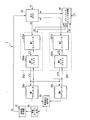
- the steam turbine 1 includes an electronic governor 10, a first controller unit 20a, a second controller unit 20b, a first actuator 30a, a second actuator 30b, and a controller unit switching.
- Unit 40 first controller unit stop instructing unit, second controller unit control instructing unit
- steam flow rate adjusting valve 50 steam turbine body 60
- rotation speed measuring instrument 70 The steam turbine body 60 rotates according to the flow rate of steam from a steam flow rate adjustment valve 50 that opens and closes according to a valve opening degree described later.
- the electronic governor 10 generates a governor command sg based on the input signal SV and the input signal PV.
- the input signal SV is a signal for instructing the electronic governor the instruction rotation speed Ns that is the target rotation speed of the steam turbine main body 60 to be controlled.
- the input signal SV is input from an operation panel (not shown).
- the input signal PV is a signal indicating an actual rotational speed N that is an actual rotational speed of the steam turbine body 60 that is a control target.
- the governor command sg is a signal for controlling the number of revolutions of the steam turbine body 60 that is a control target.
- the governor command sg is a signal indicating the valve opening degree of the steam flow control valve 50 (hereinafter referred to as “valve opening degree”).
- the valve opening degree indicates the degree of opening and closing of the valve.
- the governor command sg is a signal generated based on the difference err between the indicated rotational speed Ns of the steam turbine body 60 and the actual rotational speed N of the steam turbine body 60, and indicates the actual rotational speed N of the steam turbine body 60. Information that approaches several Ns is included.
- the electronic governor 10 transmits a governor command sg to each of the first controller unit 20a, the second controller unit 20b, and the controller unit switching unit 40.
- the first controller unit 20a is a controller unit that is used in preference to the second controller unit 20b.
- the second controller unit 20b is a spare controller unit for the first controller unit 20a.
- the first controller unit 20a controls at least one of the first actuator 30a and the second actuator 30b to be controlled. Further, the first controller unit 20a has at least one of the first actuator 30a and the second actuator 30b to be controlled until the second controller unit 20b becomes operable when a failure occurs in the first controller 201a. Control one.
- the second controller unit 20b controls at least one of the first actuator 30a and the second actuator 30b to be controlled instead of the first controller unit 20a.
- the first controller unit 20a includes a first controller 201a (a first lift command generation unit, a first lift command holding unit, a first output unit), and a first servo drive 202a.
- the first controller 201 a receives a governor command sg from the electronic governor 10.
- the first controller 201a When the first controller 201a receives the governor command sg, the first controller 201a generates the first lift command sl1 based on the governor command sg.
- the first lift command sl1 is a signal that is transmitted to the first servo drive 202a in order to control at least one of the first actuator 30a and the second actuator 30b that are controlled.
- the first lift command sl1 is a signal indicating the valve opening.
- the first controller 201a has a function of determining the occurrence of a malfunction of the first controller 201a itself.
- the first controller 201a determines that the first controller 201a is operating normally, the first controller 201a generates a first lift command sl1 indicating a valve opening that is equal to the valve opening indicated by the governor command sg. .
- the first controller 201a transmits the generated first lift command sl1 to the first servo drive 202a.
- the first controller 201a determines that a failure has occurred in the first controller 201a itself, the first controller 201a holds the first lift command sl1 transmitted to the first servo drive 202a immediately before the failure occurs.
- the first controller 201a transmits the held first lift command sl1 to the first servo drive 202a until the second controller unit 20b becomes operable.
- the first controller unit 20a transmits a switching instruction signal se1 to the controller unit switching unit 40.
- the switching instruction signal se1 is a signal instructing switching from the first controller unit 20a to the second controller unit 20b.
- the first servo drive 202a receives the first lift command sl1 from the first controller 201a. When receiving the first lift command sl1, the first servo drive 202a generates the first actuator control signal sfa1 based on the first lift command sl1.
- the first actuator control signal sfa1 is a signal obtained by amplifying the first lift command sl1 to an amplitude capable of controlling at least one of the first actuator 30a and the second actuator 30b that are controlled objects.
- the first servo drive 202a transmits a first actuator control signal sfa1 to at least one of the first actuator 30a and the second actuator 30b that are controlled objects.
- the controller unit switching unit 40 performs control to switch the first controller unit 20a to the second controller unit 20b when a failure occurs in the first controller 201a. Specifically, the controller unit switching unit 40 receives the switching instruction signal se1 from the first controller unit 20a. Upon receiving the switching instruction signal se1, the controller unit switching unit 40 transmits a switching notification signal se2 to the second controller unit 20b.
- the switching notification signal se2 is a signal for instructing that the second controller unit 20b is activated from the standby state and becomes operable.
- the controller unit switching unit 40 receives a governor command sg from the electronic governor 10.
- the controller unit switching unit 40 When the controller unit switching unit 40 receives the activation completion signal ss from the second controller unit 20b, the controller unit switching unit 40 transmits an operation stop signal stp to the first controller unit 20a.
- the activation completion signal ss is a signal for informing that the second controller unit 20b is in an operable state.
- the operation stop signal stp is a signal that causes the transmission destination functional unit to stop signal transmission.
- the second controller unit 20b includes a second controller 201b (starting unit, second lift command generating unit) and a second servo drive 202b.
- the second controller unit 20b receives the switching notification signal se2 from the controller unit switching unit 40.
- the second controller unit 20b receives the switching notification signal se2
- the second controller unit 20b is activated from the standby state and becomes operable.
- the second controller unit 20b transmits an activation completion signal ss to the controller unit switching unit 40.
- the second controller 201 b receives the governor command sg from the electronic governor 10.
- the second controller 201b generates the second lift command sl2 based on a predetermined constant rate.
- the second lift command sl2 is a signal that is transmitted to the second servo drive 202b in order to control at least one of the first actuator 30a and the second actuator 30b that are controlled.
- the second lift command sl2 is a signal indicating the valve opening.
- the second controller 201b transmits a second lift command sl2 to the second servo drive 202b.
- the second servo drive 202b receives the second lift command sl2 from the second controller 201b. Upon receiving the second lift command sl2, the second servo drive 202b generates a second actuator control signal sfa2 based on the second lift command sl2.
- the second actuator control signal sfa2 is a signal obtained by amplifying the second lift command sl2 to an amplitude that can control at least one of the first actuator 30a and the second actuator 30b that are controlled objects.
- the second servo drive 202b transmits a second actuator control signal sfa2 to at least one of the first actuator 30a and the second actuator 30b that are to be controlled.
- the first actuator 30a is an actuator used in preference to the second actuator 30b.
- the first actuator 30a receives the first actuator control signal sfa1 from the first servo drive 202a or the second actuator control signal sfa2 from the second servo drive 202b.
- the first actuator 30a operates according to the first actuator control signal sfa1 or the second actuator control signal sfa2 received at that time.
- the second actuator 30b is a spare actuator for the first actuator 30a.
- the second actuator 30b is used instead of the first actuator 30a when a failure occurs in the first actuator 30a.
- the second actuator 30b receives the first actuator control signal sfa1 from the first servo drive 202a or the second actuator control signal sfa2 from the second servo drive 202b.
- the second actuator 30b operates according to the first actuator control signal sfa1 or the second actuator control signal sfa2 received at that time.
- the steam flow rate adjusting valve 50 opens and closes at a degree of opening and closing according to the operation of the first actuator 30a or the operation of the second actuator 30b.
- the steam flow rate adjusting valve 50 adjusts the flow rate of steam supplied to the steam turbine body 60 according to the degree of opening and closing.
- the steam turbine body 60 rotates according to the flow rate of steam.
- the rotational speed measuring device 70 measures the actual rotational speed N of the steam turbine main body 60.
- the rotation speed measuring device 70 transmits the input signal PV to the electronic governor 10.
- the input signal PV includes information indicating the actual rotational speed N of the steam turbine main body 60 measured by the rotational speed measuring device 70.
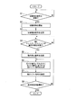
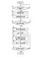
- a processing flow of the steam turbine 1 shown in FIG. 2 will be described.
- the processing flow of the steam turbine 1 shown in FIG. 2 is a processing flow when a failure occurs in the first controller 201a. Note that the process of the steam turbine 1 will be described on the assumption that the first actuator 30a is operating normally at the start of the process of the steam turbine 1 and the second actuator 30b, which is a spare actuator, is in a standby state.
- the first controller 201a has a function of determining the occurrence of a malfunction of the first controller 201a itself.
- the first controller 201a determines whether a failure has occurred in the first controller 201a itself during operation.
- the first controller 201a determines that the first controller 201a is operating normally, the first controller 201a generates a first lift command sl1 indicating a valve opening that is equal to the valve opening indicated by the governor command sg. .
- the first controller 201a transmits the generated first lift command sl1 to the first servo drive 202a. Then, the first controller 201a determines again whether or not a failure has occurred in the first controller 201a itself.
- the first controller 201a determines that a failure has occurred in the first controller 201a itself, the first controller 201a holds the first lift command sl1 transmitted to the first servo drive 202a immediately before the failure occurs. The first controller 201a transmits the held first lift command sl1 to the first servo drive 202a. The first controller unit 20a transmits a switching instruction signal se1 to the controller unit switching unit 40.
- the controller unit switching unit 40 determines whether or not the switching instruction signal se1 is received from the first controller unit 20a at predetermined time intervals (for example, every 100 ms) (step). S1). When the controller unit switching unit 40 determines that the switching instruction signal se1 is not received from the first controller unit 20a (NO in step S1), the controller unit switching unit 40 returns to the process of step S1. Further, when it is determined that the switch instruction signal se1 is received from the first controller unit 20a (YES in step S1), the controller unit switching unit 40 starts control for switching the first controller unit 20a to the second controller unit 20b. (Step S2). Specifically, when receiving the switching instruction signal se1 from the first controller unit 20a, the controller unit switching unit 40 transmits a switching notification signal se2 to the second controller unit 20b (step S3).
- the second controller unit 20b receives the switching notification signal se2 from the controller unit switching unit 40.
- the second controller unit 20b receives the switching notification signal se2
- the second controller unit 20b starts control from the standby state and becomes operable.
- the second controller unit 20b transmits an activation completion signal ss to the controller unit switching unit 40 when the activation is completed and becomes operable.
- step S4 determines that the second controller unit 20b is not in an operable state when the activation completion signal ss is not received from the second controller unit 20b. Further, the controller unit switching unit 40 determines that the second controller unit 20b is operable when it receives the activation completion signal ss from the second controller unit 20b.
- step S4 If the controller unit switching unit 40 determines that the second controller unit 20b is not in an operable state (NO in step S4), the first controller 201a transmits the held first lift command sl1 to the first servo drive 202a. The process of step S4 is performed.
- step S4 If the controller unit switching unit 40 determines that the second controller unit 20b is operable (YES in step S4), the controller unit switching unit 40 transmits an operation stop signal stp to the first controller unit 20a (step S5).
- the first controller unit 20a receives the operation stop signal stp from the controller unit switching unit 40.
- the first controller 201a stops transmitting the first lift command sl1 to the first servo drive 202a.
- the first servo drive 202a stops transmitting the first actuator control signal sfa1 to the first actuator 30a.
- the first controller 201a may be operating as long as it does not adversely affect other functional units. Further, the first controller 201a may be shut down.
- the first servo drive 202a may operate without transmitting the first actuator control signal sfa1 to the first actuator 30a as long as it does not adversely affect other functional units. Further, the first servo drive 202a may be shut down.
- the second controller 201b receives the governor command sg from the electronic governor 10 when the second controller unit 20b becomes operable.
- the second controller 201b receives the governor command sg
- the second controller 201b generates the second lift command sl2 based on the governor command sg. Specifically, the second controller 201b determines that the difference between the previous second lift command sl2 and the current second lift command sl2 is smaller than a specified value, and the valve opening and governor indicated by the second lift command sl2 A second lift command sl2 that approaches the valve opening indicated by the command sg is generated (step S6).
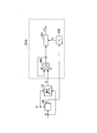
- generation of the lift command sl2 will be described with reference to a diagram showing an outline of generation of the lift command sl2 in the steam turbine 1 shown in FIG.
- command sl2 in the steam turbine 1 shown in FIG. 3 typically represents the 2nd controller 201b after the 2nd controller unit 20b will be in the state which can operate
- the second controller 201b illustrated in FIG. 3 includes a switch SW1 and a second lift command generation unit 501. When the second controller unit 20b becomes operable, the switch SW1 is on the “a1” side.
- the second lift command generator 501 has a valve opening indicated by the previous second lift command sl2 and a valve opening indicated by the current governor command sg.
- the second lift command sl2 is generated based on a predetermined constant rate whose change amount is smaller than the change amount ⁇ 2 indicated by the difference between them.
- the second lift command sl2 is a command having a change amount smaller than the change amount ⁇ 2 and bringing the valve opening degree indicated by the second lift command sl2 close to the valve opening degree indicated by the governor command sg.
- the second controller unit 20b is in a state in which the difference between the valve opening indicated by the governor command sg and the valve opening indicated by the second lift command sl2 is within a predetermined range after the second controller unit 20b becomes operable.
- the 2-lift command sl2 is a signal that suppresses a change in the actual rotational speed N of the steam turbine body 60. For example, after the second controller unit 20b becomes operable, the first time until the difference between the valve opening indicated by the governor command sg and the valve opening indicated by the second lift command sl2 falls within a predetermined range.
- the 2-lift command sl2 reduces the valve opening when the actual rotational speed N of the steam turbine body 60 is increased compared to the indicated rotational speed Ns when the second controller unit 20b is operable. It is a directive. Further, the second controller unit 20b is in an operable state until the difference between the valve opening indicated by the governor command sg and the valve opening indicated by the second lift command sl2 is within a predetermined range. The 2-lift command sl2 increases the valve opening when the actual rotational speed N of the steam turbine body 60 is reduced compared to the indicated rotational speed Ns when the second controller unit 20b becomes operable. It is a directive.
- the switch SW1 is on the “b1” side.
- the second controller 201b allows the valve indicated by the governor command sg until the difference between the valve opening indicated by the governor command sg and the valve opening indicated by the second lift command sl2 is within a predetermined range.
- the opening degree and the valve opening degree indicated by the second lift command sl2 can be brought close to each other so that the valve opening degree indicated by the governor command sg and the valve opening degree indicated by the second lift command sl2 do not change suddenly.
- the second controller 201b transmits the second lift command sl2 to the second servo drive 202b (step S7).
- step S8 Whether the difference between the valve opening degree indicated by the governor command sg and the valve opening degree indicated by the second lift command sl2 is within a predetermined range each time the second controller 201b generates the second lift command sl2. It is determined whether or not (step S8).
- step S8 If the second controller 201b determines that the difference between the valve opening indicated by the governor command sg and the valve opening indicated by the second lift command sl2 is within a predetermined range (YES in step S8), the electronic governor 10 Based on the governor command sg received from, control is returned to normal.
- step S8 when the second controller 201b determines that the difference between the valve opening indicated by the governor command sg and the valve opening indicated by the second lift command sl2 is outside the predetermined range (NO in step S8), The process returns to step S6.
- the second actuator 30b opens and closes the steam flow rate adjusting valve 50 in place of the first actuator 30a.
- a lift command sl1 indicates a first lift command sl1 between time t1 and time t2.
- the lift command sl indicates a second lift command sl2 between time t2 and time t3.
- the first controller 201a determines that a failure has occurred in the first controller 201a itself.
- the first controller 201a determines that a problem has occurred in the first controller 201a itself, the first controller unit 20a transmits a switching instruction signal se1 to the controller unit switching unit 40.
- the controller unit switching unit 40 receives the switching instruction signal se1 from the first controller unit 20a.
- the controller unit switching unit 40 transmits a switching notification signal se2 to the second controller unit 20b.
- the second controller unit 20b receives the switching notification signal se2 from the controller unit switching unit 40.
- the second controller unit 20b starts to start from the standby state.
- the second controller unit 20b is fully activated and ready to operate at time t2 shown in FIG.
- the second controller 201b receives the governor command sg from the electronic governor 10 when the second controller unit 20b becomes operable.
- the second controller 201b waits until the difference between the valve opening indicated by the governor command sg and the valve opening indicated by the second lift command sl2 falls within a predetermined range (between time t2 and time t3 shown in FIG. 4). ),
- the second lift command sl2 is generated based on a predetermined constant rate.
- the second lift command sl2 is such that the difference between the previous second lift command sl2 and the current second lift command sl2 is smaller than a specified value, and the valve opening and the governor command sg indicated by the second lift command sl2 are This is a command to bring the indicated valve opening closer.
- the second controller unit 20b is in a state in which the difference between the valve opening indicated by the governor command sg and the valve opening indicated by the second lift command sl2 is within a predetermined range after the second controller unit 20b becomes operable.
- the 2-lift command sl2 is a signal for suppressing a change (for example, a change amount, a change rate, etc.) of the actual rotational speed N of the steam turbine body 60. For example, after the second controller unit 20b becomes operable, the first time until the difference between the valve opening indicated by the governor command sg and the valve opening indicated by the second lift command sl2 falls within a predetermined range.
- the 2-lift command sl2 is a command to decrease the valve opening when the actual rotational speed N of the steam turbine body 60 is increased when the second controller unit 20b is operable. Further, the second controller unit 20b is in an operable state until the difference between the valve opening indicated by the governor command sg and the valve opening indicated by the second lift command sl2 is within a predetermined range.
- the 2-lift command sl2 is a command to increase the valve opening when the actual rotational speed N of the steam turbine body 60 is reduced when the second controller unit 20b is operable.
- the second controller 201b allows the valve indicated by the governor command sg until the difference between the valve opening indicated by the governor command sg and the valve opening indicated by the second lift command sl2 is within a predetermined range.
- the opening degree and the valve opening degree indicated by the second lift command sl2 can be brought close to each other.
- the second controller 201b After the time t3 when the difference between the valve opening degree indicated by the governor command sg and the valve opening degree indicated by the second lift command sl2 is within a predetermined range, the second controller 201b has the valve opening degree indicated by the governor command sg.
- a second lift command sl2 indicating a valve opening of the same magnitude is generated.
- the processing flow of the steam turbine 1 according to the first embodiment of the present invention has been described above.
- the steam turbine 1 includes a first controller 201a and a second controller 201b.
- the first controller 201a (first lift command generation unit) instructs the valve opening based on a governor command indicating the valve opening of the steam flow control valve 50 (flow control valve) that adjusts the rotation speed of the steam turbine 1.
- the first lift command sl1 is generated.
- the first controller 201a (first lift command holding unit) generates a first lift command generated by the first controller 201a (first lift command generation unit) at the start of switching from the first controller unit 20a to the second controller unit 20b. Holds sl1.
- the first controller 201a (first output unit) holds the first controller 201a (first lift command holding) from the start of switching from the first controller unit 20a to the second controller unit 20b until the second controller unit 20b is activated.
- the first lift command sl1 held by the unit) is transmitted.
- the second controller 201b (activation unit) activates the second controller unit 20b at the start of switching from the first controller unit 20a to the second controller unit 20b.
- the second controller 201b (second lift command generator) generates a second lift command sl2 that instructs the valve opening so that the amount of change in the valve opening is equal to or less than a predetermined amount of change.
- the steam turbine 1 can be switched smoothly (bumpless) from the 1st controller unit 20a which the malfunction generate
- the steam turbine 1 according to the present embodiment includes the electronic governor 10, the first controller unit 20a, the second controller unit 20b, the first actuator 30a, and the second actuator. 30 b, a controller unit switching unit 40, a steam flow rate adjusting valve 50, a steam turbine body 60, and a rotation speed measuring device 70.
- the first controller unit 20a includes a first controller 201a and a first servo drive 202a.
- the second controller unit 20b according to the present embodiment includes a second controller 201b and a second servo drive 202b.
- the second controller 201 b receives the governor command sg from the electronic governor 10. When the second controller 201b receives the governor command sg, the second controller 201b generates the second lift command sl2 based on the governor command sg.
- the processing flow of the steam turbine 1 according to the present embodiment is the same as the processing flow of the steam turbine 1 according to the first embodiment shown in FIG.
- the process of the steam turbine 1 according to the present embodiment differs from the specific process of step S6 in the process flow of the steam turbine 1 according to the first embodiment shown in FIG.
- the steam turbine 1 according to the present embodiment performs the processing from step S1 to step S5 in the same manner as the steam turbine 1 according to the first embodiment.
- the second controller 201b receives the governor command sg from the electronic governor 10 when the second controller unit 20b becomes operable.
- the second controller 201b When receiving the governor command sg, the second controller 201b generates a second lift command sl2 based on the governor command sg (step S6).
- generation of the lift command sl2 will be described with reference to a diagram showing an outline of generation of the lift command sl2 in the steam turbine 1 shown in FIG.
- command sl2 in the steam turbine 1 shown in FIG. 5 typically represents the 2nd controller 201b after the 2nd controller unit 20b will be in the state which can operate
- the second controller 201b starts to start from a standby state.
- the second controller unit 20b is fully activated at a time t2 shown in FIG.
- the second controller 201b receives the governor command sg from the electronic governor 10 when the second controller unit 20b becomes operable.
- the switch SW2 in FIG. 5 is switched from the “b2” side to the “a2” side.
- the switch SW2 is on the “b2” side.
- the second controller 201b detects whether the change in the valve opening indicated by the governor command sg is in the decreasing direction or the increasing direction (in FIG. 6, the increasing direction). For example, the second controller 201b starts from when the first controller unit 20a is switched to the second controller unit 20b (time t1 in FIG. 6) until the second controller unit 20b becomes operable (time t2 in FIG. 6).
- the difference between the valve opening indicated by the governor command sg and the valve opening indicated by the second lift command sl2 is a positive value, it is determined that the change in the valve opening indicated by the governor command sg is in the increasing direction.
- the second controller 201b starts from the time when the first controller unit 20a is switched to the second controller unit 20b (time t1 in FIG. 6) until the second controller unit 20b becomes operable (time t2 in FIG. 6).
- time t1 in FIG. 6 the difference between the valve opening degree indicated by the governor command sg and the valve opening degree indicated by the second lift command sl2 is a negative value, it is determined that the change in the valve opening degree indicated by the governor command sg is in a decreasing direction.
- the second controller 201b waits until the difference between the valve opening indicated by the governor command sg and the valve opening indicated by the second lift command sl2 falls within a predetermined range (between time t2 and time t3 in FIG. 6).
- the constant bias bs is calculated.
- the absolute value of the bias bs is determined in advance, and the plus / minus sign of the bias bs is determined by the difference between the valve opening degree indicated by the governor command sg and the valve opening degree indicated by the second lift command sl2.
- the second controller 201b uses this constant bias bs so that the change becomes smaller than the difference between the valve opening degree indicated by the previous second lift command sl2 and the valve opening degree indicated by the current governor command sg.
- a second lift command sl2 can be generated. For example, when the difference between the valve opening indicated by the governor command sg and the valve opening indicated by the second lift command sl2 is a positive value, the sign of the bias bs is positive.
- the second controller 201b has a predetermined short time interval (for example, every 100 ms) until the difference between the valve opening indicated by the governor command sg and the valve opening indicated by the second lift command sl2 is within a predetermined range. 2) Calculate the second lift command sl2.
- the error calculation unit 503 receives the current governor command sg received from the electronic governor 10 at the valve opening indicated by the previous governor command sg output from the delay unit 502 (described as “y (t ⁇ 1)” in FIG. 5).
- the first adder 504 adds a constant bias bs to the difference calculated by the error calculator 503.
- the second addition unit 505 is a second value indicating a valve opening obtained by adding a value obtained by adding a constant bias bs to the difference calculated by the error calculation unit 503 and the valve opening indicated by the second lift command sl2 calculated last time.
- a lift command sl2 is generated.
- the second controller 201b uses the first lift command sl1 held by the first controller 201a immediately before switching or the actual opening signal from the first actuator 30a when generating the first second lift command sl2. .
- the switch SW3 is on the “b3” side.
- the second controller 201b allows the valve indicated by the governor command sg until the difference between the valve opening indicated by the governor command sg and the valve opening indicated by the second lift command sl2 is within a predetermined range.
- the opening degree and the valve opening degree indicated by the second lift command sl2 can be brought close to each other so that the valve opening degree indicated by the governor command sg and the valve opening degree indicated by the second lift command sl2 do not change suddenly.
- the steam turbine 1 according to the present embodiment performs the processing of step S7 to step S8, similarly to the steam turbine 1 according to the first embodiment.
- a lift command sl indicates a first lift command sl1 between time t1 and time t2.
- a lift command sl2 indicates a second lift command sl2 between time t2 and time t3.
- the first controller 201a determines that a failure has occurred in the first controller 201a itself.
- the first controller 201a determines that a problem has occurred in the first controller 201a itself, the first controller unit 20a transmits a switching instruction signal se1 to the controller unit switching unit 40.
- the controller unit switching unit 40 receives the switching instruction signal se1 from the first controller unit 20a.
- the controller unit switching unit 40 transmits a switching notification signal se2 to the second controller unit 20b.
- the second controller unit 20b receives the switching notification signal se2 from the controller unit switching unit 40.
- the second controller unit 20b starts to start from the standby state.
- the second controller unit 20b is fully activated at a time t2 shown in FIG.
- the second controller 201b receives the governor command sg from the electronic governor 10 when the second controller unit 20b becomes operable.
- the opening degree of the valve indicated by the governor command sg received when the second controller unit 20b becomes operable is reduced or increased (in FIG. 6). (Increase direction) is detected.
- the second controller 201b waits until the difference between the valve opening indicated by the governor command sg and the valve opening indicated by the second lift command sl2 falls within a predetermined range (between time t2 and time t3 in FIG. 6).
- a constant bias bs (for example, 0.1% to 0.2% of the valve opening indicated by the second lift command sl2) is calculated.
- the absolute value of the bias bs is determined in advance, and the plus / minus sign of the bias bs is determined by the difference between the valve opening degree indicated by the governor command sg and the valve opening degree indicated by the second lift command sl2. For example, when the difference between the valve opening indicated by the governor command sg and the valve opening indicated by the second lift command sl2 is a positive value (that is, the valve opening indicated by the governor command sg is the valve indicated by the second lift command sl2). The sign of the bias bs is positive when it is larger than the opening.
- valve opening degree indicated by the governor command sg is a negative value (that is, the valve opening degree indicated by the governor command sg is the valve indicated by the second lift command sl2).
- the sign of the bias bs is negative.
- the second controller 201b uses this constant bias bs so that the change becomes smaller than the difference between the valve opening degree indicated by the previous second lift command sl2 and the valve opening degree indicated by the current governor command sg.
- a second lift command sl2 can be generated.
- the second controller 201b has a predetermined short time interval (for example, every 100 ms) until the difference between the valve opening indicated by the governor command sg and the valve opening indicated by the second lift command sl2 is within a predetermined range. 2) Calculate the second lift command sl2.
- the second controller 201b calculates the difference between the valve opening indicated by the previous governor command sg received from the electronic governor 10 and the valve opening indicated by the current governor command sg received from the electronic governor 10.
- the second controller 201b adds a constant bias bs to the difference between the valve opening indicated by the previous governor command sg received from the electronic governor 10 and the valve opening indicated by the current governor command sg received from the electronic governor 10. .
- the second controller 201b adds a constant bias bs to the difference between the valve opening indicated by the previous governor command sg received from the electronic governor 10 and the valve opening indicated by the current governor command sg received from the electronic governor 10.
- the second lift command sl2 calculated last time is added to the value to generate a second lift command sl2.
- the processing flow of the steam turbine 1 according to the second embodiment of the present invention has been described above.
- the steam turbine 1 includes a first controller 201a and a second controller 201b.
- the first controller 201a (first lift command generation unit) instructs the valve opening based on a governor command indicating the valve opening of the steam flow control valve 50 (flow control valve) that adjusts the rotation speed of the steam turbine 1.
- the first lift command sl1 is generated.
- the first controller 201a (first lift command holding unit) generates a first lift command generated by the first controller 201a (first lift command generation unit) at the start of switching from the first controller unit 20a to the second controller unit 20b. Holds sl1.
- the first controller 201a (first output unit) holds the first controller 201a (first lift command holding) from the start of switching from the first controller unit 20a to the second controller unit 20b until the second controller unit 20b is activated.
- the first lift command sl1 held by the unit) is transmitted.
- the second controller 201b (activation unit) activates the second controller unit 20b at the start of switching from the first controller unit 20a to the second controller unit 20b.
- the second controller 201b (second lift command generator) generates a second lift command sl2 that instructs the valve opening so that the amount of change in the valve opening is equal to or less than a predetermined amount of change.
- the second controller 201b receives the second lift command sl2 at a predetermined short time interval until the difference between the valve opening indicated by the governor command sg and the valve opening indicated by the second lift command sl2 is within a predetermined range. Is calculated.
- the second controller 201b calculates the difference between the valve opening indicated by the previous governor command sg received from the electronic governor 10 and the valve opening indicated by the current governor command sg received from the electronic governor 10.
- the second controller 201b adds a constant bias bs to the difference between the valve opening indicated by the previous governor command sg received from the electronic governor 10 and the valve opening indicated by the current governor command sg received from the electronic governor 10.
- the second controller 201b adds a constant bias bs to the difference between the valve opening indicated by the previous governor command sg received from the electronic governor 10 and the valve opening indicated by the current governor command sg received from the electronic governor 10.
- a second lift command sl2 indicating a valve opening obtained by adding the value and the valve opening indicated by the previously calculated second lift command sl2 is generated. If it does in this way, the steam turbine 1 can be switched smoothly (bumpless) from the 1st controller unit 20a which the malfunction generate
- the steam turbine 1 suppresses undershoots and overshoots that may occur when switching from the first controller unit 20a in which the failure has occurred to the spare second controller unit 20b, and suppresses failure of each functional unit. be able to.
- FIG. 7 A configuration of the steam turbine 1 according to the third embodiment of the present invention will be described.
- the steam turbine 1 according to this embodiment is similar to the steam turbine 1 according to the first embodiment.
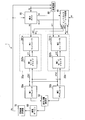
- the electronic governor 10, the first controller unit 20a, the second controller unit 20b, and the first controller An actuator 30a, a second actuator 30b, a controller unit switching unit 40, a steam flow rate adjusting valve 50, a steam turbine main body 60, and a rotation speed measuring device 70 are provided, and a difference calculating unit 80 is further provided.
- the first controller unit 20a includes a first controller 201a and a first servo drive 202a.
- the second controller unit 20b according to the present embodiment includes a second controller 201b and a second servo drive 202b.
- the difference calculation unit 80 calculates a difference err between the indicated rotational speed Ns of the steam turbine body 60 indicated by the input signal SV and the actual rotational speed N of the steam turbine body 60 indicated by the input signal PV.
- the difference calculation unit 80 transmits the difference err to the second controller 201b.
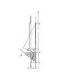
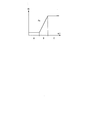
- the difference err is associated with the change rate Rt by a function Fx that is monotonously non-decreasing, for example, as shown in FIG.
- the function Fx shown in FIG. 9 includes three regions: a region A in which the difference err is small and the change rate Rt is small, a region C in which the difference err is large and the change rate Rt is large, and a region B that connects Fx between the regions A and C. Has two areas.
- the change rate Rt is a rate that defines how to change the valve opening of the steam flow control valve 50.
- the second controller 201b receives the difference err from the difference calculation unit 80. When receiving the difference err, the second controller 201b generates a second lift command sl2 based on the governor command sg and the function Fx. Specifically, the second controller 201b specifies the change rate Rt corresponding to the difference err in the function Fx shown in FIG. The second controller 201b changes the second lift command sl2 based on the specified change rate Rt.
- the processing flow of the steam turbine 1 according to the present embodiment is the processing flow of the steam turbine 1 according to the present embodiment shown in FIG.
- the steam turbine 1 according to the present embodiment performs the processing from step S1 to step S5 in the same manner as the steam turbine 1 according to the first embodiment.
- the difference calculation unit 80 After the difference calculation unit 80 itself is activated and operable, the difference calculation unit 80 is instructed by the input rotation speed Ns of the steam turbine body 60 indicated by the input signal SV and the actual rotation speed N of the steam turbine body 60 indicated by the input signal PV. And the difference err is transmitted to the second controller 201b (step S9).
- the second controller 201b receives the difference err from the difference calculation unit 80 when the second controller unit 20b becomes operable.
- the second controller 201b When receiving the difference err, the second controller 201b generates a second lift command sl2 based on the governor command sg and the function Fx (step S6).
- generation of the lift command sl2 will be described with reference to a diagram showing an outline of generation of the lift command sl2 in the steam turbine 1 shown in FIG.
- the second controller 201b illustrated in FIG. 11 includes a switch SW4, a function calculation unit 506, and a second lift command generation unit 507.
- the switch SW4 is on the “b4” side.
- the function calculation unit 506 receives the difference err from the difference calculation unit 80 after the second controller unit 20b becomes operable.
- the function calculation unit 506 identifies the change rate Rt corresponding to the difference err in the function Fx shown in FIG.
- the function calculation unit 506 transmits the specified change rate Rt to the second lift command generation unit 507.
- the second lift command generator 507 receives the change rate Rt from the function calculator 506.
- the second lift command generation unit 507 changes the second lift command sl2 based on the received change rate Rt.
- the second controller 201b transmits a second lift command sl2 to the second servo drive 202b.
- the second controller 201b allows the valve indicated by the governor command sg until the difference between the valve opening indicated by the governor command sg and the valve opening indicated by the second lift command sl2 is within a predetermined range.
- the opening degree and the valve opening degree indicated by the second lift command sl2 can be brought close to each other so that the valve opening degree indicated by the governor command sg and the valve opening degree indicated by the second lift command sl2 do not change suddenly.
- the steam turbine 1 according to the present embodiment performs the processing of step S7 to step S8, similarly to the steam turbine 1 according to the first embodiment.
- the second controller 201b When the electronic governor 10 has the function of the difference calculation unit 80 and the electronic governor 10 transmits the difference err calculated using the function of the difference calculation unit 80 to the outside, the second controller 201b The difference err may be received from 10 and the second lift command sl2 may be generated using the received difference err. In that case, the steam turbine 1 may not include the difference calculation unit 80.
- the second lift command sl2 corresponding to the change rate Rt generated by the second controller 201b based on the data table TBL1 is, for example, the lift command sl from time t2 to time t3 shown in FIG.
- the lift command sl indicates the first lift command sl1 between time t1 and time t2.
- a lift command sl indicates a second lift command sl2 between time t2 and time t4.
- the slope of the lift command sl2 between time t2 and time t4 shown in FIG. 12 is the slope in the region C of the difference err shown in FIG.
- the second controller 201b transmits a second lift command sl2 to the second servo drive 202b.
- the processing flow of the steam turbine 1 according to the third embodiment of the present invention has been described above.
- the steam turbine 1 includes a first controller 201a and a second controller 201b.
- the first controller 201a (first lift command generation unit) instructs the valve opening based on a governor command indicating the valve opening of the steam flow control valve 50 (flow control valve) that adjusts the rotation speed of the steam turbine 1.
- the first lift command sl1 is generated.
- the first controller 201a (first lift command holding unit) generates a first lift command generated by the first controller 201a (first lift command generation unit) at the start of switching from the first controller unit 20a to the second controller unit 20b. Holds sl1.
- the first controller 201a (first output unit) holds the first controller 201a (first lift command holding) from the start of switching from the first controller unit 20a to the second controller unit 20b until the second controller unit 20b is activated.
- the first lift command sl1 held by the unit) is transmitted.
- the second controller 201b (activation unit) activates the second controller unit 20b at the start of switching from the first controller unit 20a to the second controller unit 20b.
- the second controller 201b (second lift command generator) generates a second lift command sl2 that instructs the valve opening so that the amount of change in the valve opening is equal to or less than a predetermined amount of change.
- the difference calculation unit 80 starts the steam turbine main body 60 indicated by the instruction rotation speed Ns of the steam turbine main body 60 indicated by the input signal SV and the input signal PV.
- the difference err with the actual rotational speed N is calculated, and the difference err is transmitted to the second controller 201b.
- the second controller 201b receives the difference err from the difference calculation unit 80 after the second controller unit 20b becomes operable.
- the second controller 201b When receiving the difference err, the second controller 201b generates a second lift command sl2 based on the governor command sg and the function Fx.
- the second controller 201b transmits a second lift command sl2 to the second servo drive 202b.
- the steam turbine 1 can be switched smoothly (bumpless) from the 1st controller unit 20a which the malfunction generate
- the steam turbine 1 according to this embodiment includes an electronic governor 10, a first controller unit 20a, a second controller unit 20b, a first actuator 30a, a second actuator 30b, and a controller unit switching.
- Unit 40 steam flow control valve 50, steam turbine main body 60, rotation speed measuring device 70, and difference calculation unit 80.
- the first controller unit 20a includes a first controller 201a and a first servo drive 202a.
- the second controller unit 20b according to the present embodiment includes a second controller 201b and a second servo drive 202b.
- the actual rotation speed N of the steam turbine body 60 indicated by the input signal PV is the actual rotation of the steam turbine body 60 immediately before the malfunction occurs in the first controller 201a. It is determined whether or not the rotation speed is within a range of a predetermined rotation speed set based on the number N.
- the range from the upper limit to the lower limit of the predetermined rotational speed set based on the actual rotational speed N of the steam turbine main body 60 immediately before the malfunction occurs in the first controller 201a is, for example, immediately before the malfunction occurs in the first controller 201a.
- the actual rotation speed N of the steam turbine main body 60 is within a range of ⁇ 5%.
- the actual rotational speed N of the steam turbine body 60 indicated by the input signal PV is a predetermined rotational speed set based on the actual rotational speed N of the steam turbine body 60 immediately before the first controller 201a malfunctions. If it is determined that it is within the range, the notification signal si is transmitted to the second controller 201b.
- the notification signal si is a predetermined number of revolutions set based on the actual number of revolutions N of the steam turbine body 60 immediately before the malfunction of the first controller 201a occurs. It is a signal which notifies that it is in the range.
- the electronic governor 10 transmits a governor command sg to the second controller 201b.
- the difference calculation unit 80 transmits the difference err to the second controller 201b.
- the second controller 201b receives the difference err from the difference calculation unit 80. When receiving the difference err, the second controller 201b generates a second lift command sl2 based on the difference err and the function Fx. Note that the second controller 201b determines whether or not the notification signal si is received from the electronic governor 10. When the second controller 201b determines that the notification signal si has been received from the electronic governor 10, the range of the valve opening indicated by the second lift command sl2 is determined for the steam turbine body 60 immediately before the first controller 201a has a problem.
- the predetermined rotational speed set with reference to the actual rotational speed N is limited to a valve opening range that sets the predetermined rotational speed.
- the second controller 201b determines that the notification signal si is not received from the electronic governor 10, the second controller 201b does not limit the range of the valve opening indicated by the second lift command sl2.
- the second controller 201 b receives the governor command sg from the electronic governor 10.
- the second controller 201b generates the second lift command sl2 based on the governor command sg.
- the processing flow of the steam turbine 1 according to the present embodiment is the processing flow of the steam turbine 1 according to the present embodiment shown in FIG.
- the steam turbine 1 according to the present embodiment performs the processing of step S1 to step S5 and step S9 in the same manner as the steam turbine 1 according to the first embodiment.
- the second controller 201b receives the difference err from the electronic governor 10.
- the second controller 201b When the second controller 201b receives the difference err, the second controller 201b generates a second lift command sl2 (step S6).
- generation of the lift command sl2 will be described with reference to a diagram showing an outline of generation of the lift command sl2 in the steam turbine 1 shown in FIG.
- command sl2 in the steam turbine 1 shown in FIG. 11 is the electronic governor 10 after the 2nd controller unit 20b will be in the operable state, the difference calculating part 80, and a 2nd controller. 201b is schematically shown.
- the 11 includes a switch SW4, a function calculation unit 506, and a second lift command generation unit 507.
- the switch SW4 is on the “b4” side.
- the function calculation unit 506 receives the difference err from the difference calculation unit 80 after the second controller unit 20b becomes operable.
- the function calculation unit 506 identifies the change rate Rt corresponding to the difference err in the function Fx shown in FIG.
- the function calculation unit 506 transmits the specified change rate Rt to the second lift command generation unit 507.
- the second lift command generator 507 receives the change rate Rt from the function calculator 506.
- the second lift command generation unit 507 changes the second lift command sl2 based on the received change rate Rt.
- the actual rotation speed N of the steam turbine body 60 indicated by the input signal PV is the actual rotation of the steam turbine body 60 just before the malfunction occurs in the first controller 201a. It is determined whether or not the rotation speed is within a range of a predetermined rotation speed set based on the number N.
- the range from the upper limit to the lower limit of the predetermined rotational speed set based on the actual rotational speed N of the steam turbine main body 60 immediately before the malfunction occurs in the first controller 201a is, for example, immediately before the malfunction occurs in the first controller 201a.
- the actual rotation speed N of the steam turbine main body 60 is within a range of ⁇ 5%.
- the actual rotational speed N of the steam turbine body 60 indicated by the input signal PV is a predetermined rotational speed set based on the actual rotational speed N of the steam turbine body 60 immediately before the first controller 201a malfunctions. If it is determined that it is within the range, the notification signal si is transmitted to the second controller 201b.
- the second controller 201b determines whether or not the notification signal si is received from the electronic governor 10 (step S10). If the second controller 201b determines that the notification signal si has been received from the electronic governor 10 (YES in step S10), the valve opening range indicated by the second lift command sl2 is set immediately before the first controller 201a has a problem.
- the predetermined rotational speed set based on the actual rotational speed N of the steam turbine main body 60 is limited to a valve opening range that sets the predetermined rotational speed (step S11). If the second controller 201b determines that the notification signal si is not received from the electronic governor 10 (NO in step S10), the second controller 201b does not limit the range of the valve opening indicated by the second lift command sl2.
- the second controller 201b allows the governor command until the difference between the valve opening indicated by the governor command sg and the valve opening indicated by the second lift command sl2 is within a predetermined valve opening range.
- the valve opening indicated by sg and the valve opening indicated by the second lift command sl2 are brought close to each other so that the valve opening indicated by the governor command sg and the valve opening indicated by the second lift command sl2 do not change suddenly. Can do.
- the steam turbine 1 according to the present embodiment performs the processing of step S7 to step S8, similarly to the steam turbine 1 according to the first embodiment.
- a lift command sl1 indicates a first lift command sl1 between time t1 and time t2.
- the lift command sl indicates a second lift command sl2 between time t2 and time t3.
- the first controller 201a determines that a failure has occurred in the first controller 201a itself.
- the first controller 201a determines that a problem has occurred in the first controller 201a itself, the first controller unit 20a transmits a switching instruction signal se1 to the controller unit switching unit 40.
- the controller unit switching unit 40 receives the switching instruction signal se1 from the first controller unit 20a.
- the controller unit switching unit 40 transmits a switching notification signal se2 to the second controller unit 20b.
- the second controller unit 20b receives the switching notification signal se2 from the controller unit switching unit 40.
- the second controller unit 20b starts to start from the standby state.
- the second controller unit 20b is fully activated at a time t2 shown in FIG.
- the second controller 201b When the second controller unit 20b is in an operable state, the second controller 201b is in a period from when the second controller unit 20b is in an operable state until the notification signal si is received (from time t2 shown in FIG. 14). During time t4), the change rate Rt corresponding to the difference err is received from the difference calculation unit 80. The second controller 201b generates a second lift command sl2 based on the change rate Rt. The second controller 201b transmits a second lift command sl2 to the second servo drive 202b.
- the second controller 201b When the second controller 201b receives the notification signal si that receives the notification signal si from the electronic governor 10, the second rotation speed Ns of the steam turbine body 60 indicated by the input signal SV and the actual rotation of the steam turbine body 60 indicated by the input signal PV are received.
- a governor command sg is received from the electronic governor 10 to indicate the valve opening degree for setting the rotational speed whose change is smaller than the difference from the number N.
- the second controller 201b sets the actual rotational speed N of the steam turbine body 60 based on the actual rotational speed N of the steam turbine body 60 immediately before the first controller 201a malfunctions.
- a second lift command sl2 is generated that indicates the valve opening that falls within the range from the upper limit to the lower limit of the valve opening that sets the number of revolutions.
- the second controller 201b transmits a second lift command sl2 to the second servo drive 202b.
- the processing flow of the steam turbine 1 according to the fourth embodiment of the present invention has been described above.
- the steam turbine 1 includes a first controller 201a and a second controller 201b.
- the first controller 201a (first lift command generation unit) instructs the valve opening based on a governor command indicating the valve opening of the steam flow control valve 50 (flow control valve) that adjusts the rotation speed of the steam turbine 1.
- the first lift command sl1 is generated.
- the first controller 201a (first lift command holding unit) generates a first lift command generated by the first controller 201a (first lift command generation unit) at the start of switching from the first controller unit 20a to the second controller unit 20b. Hold.
- the first controller 201a (first output unit) holds the first controller 201a (first lift command holding) from the start of switching from the first controller unit 20a to the second controller unit 20b until the second controller unit 20b is activated.
- the first lift command sl1 held by the unit) is transmitted.
- the second controller 201b (activation unit) activates the second controller unit 20b at the start of switching from the first controller unit 20a to the second controller unit 20b.
- the second controller 201b (second lift command generator) generates a second lift command sl2 that instructs the valve opening so that the amount of change in the valve opening is equal to or less than a predetermined amount of change.
- the second controller 201b sets the predetermined rotational speed at which the actual rotational speed N of the steam turbine main body 60 is set based on the actual rotational speed N of the steam turbine main body 60 immediately before a failure occurs in the first controller 201a.
- the second lift command sl2 is generated based on the difference between the indicated rotational speed Ns of the steam turbine body 60 and the actual rotational speed N of the steam turbine body 60 until the valve opening is set within the range of the valve opening.
- the second controller 201b sets a predetermined rotational speed, which is set based on the actual rotational speed N of the steam turbine main body 60 immediately before the malfunction occurs in the first controller 201a.
- the actual rotation of the steam turbine main body 60 until the difference between the valve opening indicated by the governor command sg and the valve opening indicated by the second lift command sl2 is within a predetermined range after being within the valve opening range.
- the number N is set based on the actual rotational speed N of the steam turbine body 60 immediately before the malfunction occurs in the first controller 201a, and the actual rotational speed N of the steam turbine body 60 just before the malfunction occurs in the first controller 201a.
- a second lift command sl2 is generated by providing a restriction within the range of the valve opening that sets the predetermined rotational speed.
- the second controller unit 20b transmits the second lift command sl2 to the actuator to be controlled.
- the steam turbine 1 can be switched smoothly (bumpless) from the 1st controller unit 20a which the malfunction generate
- the controller unit switching unit 40 has been described as receiving the switching instruction signal se1 from the first controller 201a.
- the controller unit switching unit 40 according to the embodiment of the present invention is not limited thereto.
- the controller unit switching unit 40 may be such that the controller unit switching unit 40 directly receives the switching instruction signal se1 by an operation by a maintenance worker.
- the turbine according to the embodiment of the present invention is not limited to a steam turbine.
- the actual rotational speed N of the gas turbine may be controlled by controlling the flow rate of the gas in the gas turbine.
- the second controller 201b has been described as generating the second lift command sl2 based on a predetermined constant rate.
- the second controller 201b is not limited thereto.
- the second controller 201b has been described as providing a restriction so that the valve opening indicated by the second lift command sl2 is within a predetermined valve opening range. .
- what restricts the valve opening indicated by the second lift command sl2 to be within the range of the predetermined valve opening may be the second lift command sl2 in a turbine other than the fourth embodiment. .
- the order of processing may be changed within a range where appropriate processing is performed.
- the storage unit included in the first controller 201a in the present invention and each of the other storage units may be provided anywhere within a range where appropriate information is transmitted and received.
- each of the storage unit included in the first controller 201a and other storage units may exist in a range where appropriate information is transmitted and received, and data may be distributed and stored.
- the above-described steam turbine 1 may have a computer system therein.
- the process described above is stored in a computer-readable recording medium in the form of a program, and the above process is performed by the computer reading and executing this program.
- the computer-readable recording medium means a magnetic disk, a magneto-optical disk, a CD-ROM, a DVD-ROM, a semiconductor memory, or the like.
- the computer program may be distributed to the computer via a communication line, and the computer that has received the distribution may execute the program.
- the above program may realize part of the functions described above. Further, the program may be a so-called difference file (difference program) that can realize the above-described functions in combination with a program already recorded in the computer system.
- difference file difference program
Landscapes
- Engineering & Computer Science (AREA)
- Mechanical Engineering (AREA)
- General Engineering & Computer Science (AREA)
- Chemical & Material Sciences (AREA)
- Combustion & Propulsion (AREA)
- Physics & Mathematics (AREA)
- Fluid Mechanics (AREA)
- Control Of Turbines (AREA)
Abstract
タービンの第1コントローラは、流量調節弁の弁開度を示すガバナ指令に基づいて、弁開度を指示する第1リフト指令を生成する。第1コントローラは、第1コントローラユニットから第2コントローラユニットへの切り替え開始時に、第1リフト指令を保持する。第1コントローラは、前記切り替え開始から第2コントローラユニットが起動するまでの間、第1リフト指令を送信する。第2コントローラは、前記切り替え開始時に、第2コントローラユニットを起動させる。第2コントローラは、弁開度の変化量が所定の変化量以下となるような弁開度を指示する第2リフト指令を生成する。
Description
本発明は、タービン、制御方法及びプログラムに関する。
本願は、2016年01月18日に、日本に出願された特願2016-007271号に基づき優先権を主張し、その内容をここに援用する。
本願は、2016年01月18日に、日本に出願された特願2016-007271号に基づき優先権を主張し、その内容をここに援用する。
タービンは、一般的に、動作を開始すると長期間動作が継続する場合が多く、不具合に対する対策は重要である。
特許文献1、特許文献2には、関連する技術として、タービンを制御する予備の制御装置を備える技術が記載されている。
特許文献1、特許文献2には、関連する技術として、タービンを制御する予備の制御装置を備える技術が記載されている。
特許文献1の技術では、タービンにおいて通常時に使用されている制御装置から予備の制御装置に切り替える詳細な方法が示されていない。また、特許文献2の技術は、タービンにおいて予備の制御装置に対して積分演算の初期値を準備するものである。
一般的に、タービンにおいて、通常時に使用されている制御装置から予備の制御装置に切り替える場合、予備の制御装置が起動を開始してから動作可能な状態になるまでの時間が短いことが望ましいが、予備の制御装置の起動に時間を要する場合、アクチュエータを制御する目標指令が示す目標値と、アクチュエータが結果として出力する実測値との差が大きくなる。そのため、タービンにおいて、通常時に使用されている制御装置と予備の制御装置の接続を単純に切り替えると、その目標値と実測値との大きな差により、その制御装置の切り替え後のアクチュエータの動作が現在の動作と大きく異なることになる。そして、その制御装置の切り替え前後のアクチュエータの動作の違いにより、アクチュエータに破損などの不具合が生じる可能性がある。
そのため、タービンにおいて通常時に使用されている制御装置から予備の制御装置へよりスムーズに(バンプレスに)切り替えることのできる技術が求められていた。
一般的に、タービンにおいて、通常時に使用されている制御装置から予備の制御装置に切り替える場合、予備の制御装置が起動を開始してから動作可能な状態になるまでの時間が短いことが望ましいが、予備の制御装置の起動に時間を要する場合、アクチュエータを制御する目標指令が示す目標値と、アクチュエータが結果として出力する実測値との差が大きくなる。そのため、タービンにおいて、通常時に使用されている制御装置と予備の制御装置の接続を単純に切り替えると、その目標値と実測値との大きな差により、その制御装置の切り替え後のアクチュエータの動作が現在の動作と大きく異なることになる。そして、その制御装置の切り替え前後のアクチュエータの動作の違いにより、アクチュエータに破損などの不具合が生じる可能性がある。
そのため、タービンにおいて通常時に使用されている制御装置から予備の制御装置へよりスムーズに(バンプレスに)切り替えることのできる技術が求められていた。
本発明は、上記の課題を解決することのできるタービン、制御方法及びプログラムを提供することを目的としている。
本発明の第1の態様によれば、タービンは、第1コントローラと第2コントローラとを備えるタービンであって、前記第1コントローラは、タービンの回転数を調整する流量調節弁の弁開度を示すガバナ指令に基づいて、前記弁開度を指示する第1リフト指令を生成する第1リフト指令生成部と、第1コントローラユニットから第2コントローラユニットへの切り替え開始時に、前記第1リフト指令生成部が生成した前記第1リフト指令を保持する第1リフト指令保持部と、前記切り替え開始から前記第2コントローラユニットが起動するまでの間、前記第1リフト指令保持部が保持した第1リフト指令を送信する第1出力部と、を備え、前記第2コントローラは、前記切り替え開始時に、前記第2コントローラユニットを起動させる起動部と、前記弁開度の変化量が所定の変化量以下となるような弁開度を指示する第2リフト指令を生成する第2リフト指令生成部と、を備える。
本発明の第2の態様によれば、第1の態様におけるタービンにおいて、前記第2コントローラは、一定のバイアスが示す弁開度と、前回の第2リフト指令が示す弁開度と、前記前回のガバナ指令が示す弁開度と今回のガバナ指令が示す弁開度との差とを加算した弁開度を示す第2リフト指令を生成してもよい。
本発明の第3の態様によれば、第1の態様におけるタービンにおいて、前記第2コントローラは、タービン本体の指示回転数とタービン本体の実回転数との差と、当該差に対応する変化レートとの関係を示す関数に基づいて前記変化量を設定する第2リフト指令を生成してもよい。
本発明の第4の態様によれば、第1の態様におけるタービンにおいて、前記第2コントローラは、タービン本体の実回転数が前記切り替え開始の直前のタービン本体の実回転数を基準に設定した所定の弁開度の範囲内となってから前記ガバナ指令が示す弁開度と前記第2リフト指令が示す弁開度との差が所定の範囲内となるまでの間、タービン本体の指示回転数とタービン本体の実回転数との差に基づいて前記変化量を設定する第2リフト指令を生成してもよい。
本発明の第5の態様によれば、第1の態様から第4の態様の何れかの態様におけるタービンは、前記切り替えが開始し前記第2コントローラユニットが動作可能な状態になると、前記第1コントローラユニットからアクチュエータへの制御信号の送信を停止させる第1コントローラユニット停止指示部と、前記切り替えが開始し前記第2コントローラユニットが動作可能な状態になると、前記ガバナ指令が示す弁開度と第2リフト指令が示す弁開度との差が所定の弁開度の範囲内となるまで、前記第2コントローラユニットに前記アクチュエータを制御させる第2コントローラユニット制御指示部と、を備えていてもよい。
本発明の第6の態様によれば、タービンの制御方法は、タービンの回転数を調整する流量調節弁の弁開度を示すガバナ指令に基づいて、前記弁開度を指示する第1リフト指令を生成すること、第1コントローラユニットから第2コントローラユニットへの切り替え開始時に、前記第1リフト指令を保持すること、前記切り替え開始から前記第2コントローラユニットが起動するまでの間、前記第1リフト指令を送信すること、前記切り替え開始時に、前記第2コントローラユニットを起動させること、前記弁開度の変化量が所定の変化量以下となるような弁開度を指示する第2リフト指令を生成すること、を含む。
本発明の第7の態様によれば、プログラムは、コンピュータに、タービンの回転数を調整する流量調節弁の弁開度を示すガバナ指令に基づいて、前記弁開度を指示する第1リフト指令を生成すること、第1コントローラユニットから第2コントローラユニットへの切り替え開始時に、前記第1リフト指令を保持すること、前記切り替え開始から前記第2コントローラユニットが起動するまでの間、前記第1リフト指令を送信すること、前記切り替え開始時に、前記第2コントローラユニットを起動させること、前記弁開度の変化量が所定の変化量以下となるような弁開度を指示する第2リフト指令を生成すること、を実行させる。
上述のタービン、制御方法及びプログラムによれば、不具合が発生した制御装置から予備の制御装置へよりスムーズに切り替えることができる。
<第一の実施形態>
以下、図面を参照しながら実施形態について詳しく説明する。
本発明の第一の実施形態による蒸気タービン1の構成について説明する。
本実施形態による蒸気タービン1は、図1に示すように、電子ガバナ10と、第1コントローラユニット20aと、第2コントローラユニット20bと、第1アクチュエータ30aと、第2アクチュエータ30bと、コントローラユニット切替部40(第1コントローラユニット停止指示部、第2コントローラユニット制御指示部)と、蒸気流量調節弁50と、蒸気タービン本体60と、回転数計測器70と、を備える。
蒸気タービン本体60は、後述する弁開度に応じて開閉する蒸気流量調節弁50からの蒸気の流量によって回転する。
以下、図面を参照しながら実施形態について詳しく説明する。
本発明の第一の実施形態による蒸気タービン1の構成について説明する。
本実施形態による蒸気タービン1は、図1に示すように、電子ガバナ10と、第1コントローラユニット20aと、第2コントローラユニット20bと、第1アクチュエータ30aと、第2アクチュエータ30bと、コントローラユニット切替部40(第1コントローラユニット停止指示部、第2コントローラユニット制御指示部)と、蒸気流量調節弁50と、蒸気タービン本体60と、回転数計測器70と、を備える。
蒸気タービン本体60は、後述する弁開度に応じて開閉する蒸気流量調節弁50からの蒸気の流量によって回転する。
電子ガバナ10は、入力信号SVと入力信号PVとに基づいて、ガバナ指令sgを生成する。入力信号SVは、制御対象である蒸気タービン本体60の目標回転数である指示回転数Nsを電子ガバナに指示する信号である。入力信号SVは、図示していない操作盤などから入力される。入力信号PVは、制御対象である蒸気タービン本体60の実際の回転数である実回転数Nを示す信号である。ガバナ指令sgは、制御対象である蒸気タービン本体60の回転数を制御するための信号である。ガバナ指令sgは、蒸気流量調節弁50の弁開度(以下、「弁開度」と記載)を示す信号である。弁開度は、弁の開閉の度合いを示す。ガバナ指令sgは、蒸気タービン本体60の指示回転数Nsと蒸気タービン本体60の実回転数Nとの差errに基づいて生成される信号であり、蒸気タービン本体60の実回転数Nを指示回転数Nsに近づける情報を含んでいる。
電子ガバナ10は、第1コントローラユニット20a、第2コントローラユニット20b、コントローラユニット切替部40のそれぞれにガバナ指令sgを送信する。
電子ガバナ10は、第1コントローラユニット20a、第2コントローラユニット20b、コントローラユニット切替部40のそれぞれにガバナ指令sgを送信する。
第1コントローラユニット20aは、第2コントローラユニット20bに優先して用いられるコントローラユニットである。
第2コントローラユニット20bは、第1コントローラユニット20aに対する予備のコントローラユニットである。
第1コントローラユニット20aは、第1コントローラユニット20a自身が正常に動作している場合に、制御対象である第1アクチュエータ30a及び第2アクチュエータ30bの少なくとも一方を制御する。また、第1コントローラユニット20aは、第1コントローラ201aに不具合が発生した場合に、第2コントローラユニット20bが動作可能な状態になるまで、制御対象である第1アクチュエータ30a及び第2アクチュエータ30bの少なくとも一方を制御する。
第2コントローラユニット20bは、第1コントローラユニット20aに不具合が発生した場合に、第1コントローラユニット20aの代わりに制御対象である第1アクチュエータ30a及び第2アクチュエータ30bの少なくとも一方を制御する。
第2コントローラユニット20bは、第1コントローラユニット20aに対する予備のコントローラユニットである。
第1コントローラユニット20aは、第1コントローラユニット20a自身が正常に動作している場合に、制御対象である第1アクチュエータ30a及び第2アクチュエータ30bの少なくとも一方を制御する。また、第1コントローラユニット20aは、第1コントローラ201aに不具合が発生した場合に、第2コントローラユニット20bが動作可能な状態になるまで、制御対象である第1アクチュエータ30a及び第2アクチュエータ30bの少なくとも一方を制御する。
第2コントローラユニット20bは、第1コントローラユニット20aに不具合が発生した場合に、第1コントローラユニット20aの代わりに制御対象である第1アクチュエータ30a及び第2アクチュエータ30bの少なくとも一方を制御する。
第1コントローラユニット20aは、第1コントローラ201a(第1リフト指令生成部、第1リフト指令保持部、第1出力部)と、第1サーボドライブ202aと、を備える。
第1コントローラ201aは、電子ガバナ10からガバナ指令sgを受信する。
第1コントローラ201aは、ガバナ指令sgを受信すると、ガバナ指令sgに基づいて、第1リフト指令sl1を生成する。第1リフト指令sl1は、制御対象である第1アクチュエータ30a及び第2アクチュエータ30bの少なくとも一方を制御するために第1サーボドライブ202aに送信する信号である。第1リフト指令sl1は、弁開度を示す信号である。
第1コントローラ201aは、第1コントローラ201a自身の不具合の発生を判定する機能を有している。
第1コントローラ201aは、第1コントローラ201a自身が正常に動作していると判定した場合、ガバナ指令sgが示す弁開度と同等の大きさの弁開度を示す第1リフト指令sl1を生成する。第1コントローラ201aは、生成した第1リフト指令sl1を第1サーボドライブ202aに送信する。
第1コントローラ201aは、第1コントローラ201a自身に不具合が発生したと判定した場合、その不具合が発生する直前に第1サーボドライブ202aに送信した第1リフト指令sl1を保持する。第1コントローラ201aは、第2コントローラユニット20bが動作可能な状態になるまで、保持した第1リフト指令sl1を第1サーボドライブ202aに送信する。第1コントローラユニット20aは、切替指示信号se1をコントローラユニット切替部40に送信する。切替指示信号se1は、第1コントローラユニット20aから第2コントローラユニット20bへの切替を指示する信号である。
第1コントローラ201aは、電子ガバナ10からガバナ指令sgを受信する。
第1コントローラ201aは、ガバナ指令sgを受信すると、ガバナ指令sgに基づいて、第1リフト指令sl1を生成する。第1リフト指令sl1は、制御対象である第1アクチュエータ30a及び第2アクチュエータ30bの少なくとも一方を制御するために第1サーボドライブ202aに送信する信号である。第1リフト指令sl1は、弁開度を示す信号である。
第1コントローラ201aは、第1コントローラ201a自身の不具合の発生を判定する機能を有している。
第1コントローラ201aは、第1コントローラ201a自身が正常に動作していると判定した場合、ガバナ指令sgが示す弁開度と同等の大きさの弁開度を示す第1リフト指令sl1を生成する。第1コントローラ201aは、生成した第1リフト指令sl1を第1サーボドライブ202aに送信する。
第1コントローラ201aは、第1コントローラ201a自身に不具合が発生したと判定した場合、その不具合が発生する直前に第1サーボドライブ202aに送信した第1リフト指令sl1を保持する。第1コントローラ201aは、第2コントローラユニット20bが動作可能な状態になるまで、保持した第1リフト指令sl1を第1サーボドライブ202aに送信する。第1コントローラユニット20aは、切替指示信号se1をコントローラユニット切替部40に送信する。切替指示信号se1は、第1コントローラユニット20aから第2コントローラユニット20bへの切替を指示する信号である。
第1サーボドライブ202aは、第1コントローラ201aから第1リフト指令sl1を受信する。
第1サーボドライブ202aは、第1リフト指令sl1を受信すると、第1リフト指令sl1に基づいて、第1アクチュエータ制御信号sfa1を生成する。第1アクチュエータ制御信号sfa1は、第1リフト指令sl1を、制御対象である第1アクチュエータ30a及び第2アクチュエータ30bの少なくとも一方を制御可能な振幅まで増幅した信号である。
第1サーボドライブ202aは、制御対象である第1アクチュエータ30a及び第2アクチュエータ30bの少なくとも一方に第1アクチュエータ制御信号sfa1を送信する。
第1サーボドライブ202aは、第1リフト指令sl1を受信すると、第1リフト指令sl1に基づいて、第1アクチュエータ制御信号sfa1を生成する。第1アクチュエータ制御信号sfa1は、第1リフト指令sl1を、制御対象である第1アクチュエータ30a及び第2アクチュエータ30bの少なくとも一方を制御可能な振幅まで増幅した信号である。
第1サーボドライブ202aは、制御対象である第1アクチュエータ30a及び第2アクチュエータ30bの少なくとも一方に第1アクチュエータ制御信号sfa1を送信する。
コントローラユニット切替部40は、第1コントローラ201aに不具合が発生した場合に、第1コントローラユニット20aを第2コントローラユニット20bに切り替える制御を行う。具体的には、コントローラユニット切替部40は、第1コントローラユニット20aから切替指示信号se1を受信する。コントローラユニット切替部40は、切替指示信号se1を受信すると、第2コントローラユニット20bに切替報知信号se2を送信する。切替報知信号se2は、第2コントローラユニット20bが待機状態から起動させ動作可能な状態になることを指示する信号である。
コントローラユニット切替部40は、電子ガバナ10からガバナ指令sgを受信する。
コントローラユニット切替部40は、起動完了信号ssを第2コントローラユニット20bから受信すると、動作停止信号stpを第1コントローラユニット20aに送信する。起動完了信号ssは、第2コントローラユニット20bが動作可能な状態になったことを報知する信号である。動作停止信号stpは、送信先の機能部に信号の送信を停止させる信号である。
コントローラユニット切替部40は、電子ガバナ10からガバナ指令sgを受信する。
コントローラユニット切替部40は、起動完了信号ssを第2コントローラユニット20bから受信すると、動作停止信号stpを第1コントローラユニット20aに送信する。起動完了信号ssは、第2コントローラユニット20bが動作可能な状態になったことを報知する信号である。動作停止信号stpは、送信先の機能部に信号の送信を停止させる信号である。
第2コントローラユニット20bは、第2コントローラ201b(起動部、第2リフト指令生成部)と、第2サーボドライブ202bと、を備える。
第2コントローラユニット20bは、コントローラユニット切替部40から切替報知信号se2を受信する。
第2コントローラユニット20bは、切替報知信号se2を受信すると、待機状態から起動し動作可能な状態になる。
第2コントローラユニット20bは、動作可能な状態になると、起動完了信号ssをコントローラユニット切替部40に送信する。
第2コントローラユニット20bは、コントローラユニット切替部40から切替報知信号se2を受信する。
第2コントローラユニット20bは、切替報知信号se2を受信すると、待機状態から起動し動作可能な状態になる。
第2コントローラユニット20bは、動作可能な状態になると、起動完了信号ssをコントローラユニット切替部40に送信する。
第2コントローラ201bは、電子ガバナ10からガバナ指令sgを受信する。
第2コントローラ201bは、予め定めた一定レートに基づいて、第2リフト指令sl2を生成する。第2リフト指令sl2は、制御対象である第1アクチュエータ30a及び第2アクチュエータ30bの少なくとも一方を制御するために第2サーボドライブ202bに送信する信号である。第2リフト指令sl2は、弁開度を示す信号である。
第2コントローラ201bは、第2リフト指令sl2を第2サーボドライブ202bに送信する。
第2コントローラ201bは、予め定めた一定レートに基づいて、第2リフト指令sl2を生成する。第2リフト指令sl2は、制御対象である第1アクチュエータ30a及び第2アクチュエータ30bの少なくとも一方を制御するために第2サーボドライブ202bに送信する信号である。第2リフト指令sl2は、弁開度を示す信号である。
第2コントローラ201bは、第2リフト指令sl2を第2サーボドライブ202bに送信する。
第2サーボドライブ202bは、第2コントローラ201bから第2リフト指令sl2を受信する。第2サーボドライブ202bは、第2リフト指令sl2を受信すると、第2リフト指令sl2に基づいて、第2アクチュエータ制御信号sfa2を生成する。第2アクチュエータ制御信号sfa2は、第2リフト指令sl2を、制御対象である第1アクチュエータ30a及び第2アクチュエータ30bの少なくとも一方を制御可能な振幅まで増幅した信号である。
第2サーボドライブ202bは、制御対象である第1アクチュエータ30a及び第2アクチュエータ30bの少なくとも一方に第2アクチュエータ制御信号sfa2を送信する。
第2サーボドライブ202bは、制御対象である第1アクチュエータ30a及び第2アクチュエータ30bの少なくとも一方に第2アクチュエータ制御信号sfa2を送信する。
第1アクチュエータ30aは、第2アクチュエータ30bに優先して用いられるアクチュエータである。
第1アクチュエータ30aは、第1サーボドライブ202aから第1アクチュエータ制御信号sfa1を、または、第2サーボドライブ202bから第2アクチュエータ制御信号sfa2を受信する。
第1アクチュエータ30aは、そのときに受信した第1アクチュエータ制御信号sfa1または第2アクチュエータ制御信号sfa2に応じて動作する。
第1アクチュエータ30aは、第1サーボドライブ202aから第1アクチュエータ制御信号sfa1を、または、第2サーボドライブ202bから第2アクチュエータ制御信号sfa2を受信する。
第1アクチュエータ30aは、そのときに受信した第1アクチュエータ制御信号sfa1または第2アクチュエータ制御信号sfa2に応じて動作する。
第2アクチュエータ30bは、第1アクチュエータ30aに対する予備のアクチュエータである。第2アクチュエータ30bは、第1アクチュエータ30aに不具合が発生した場合に、第1アクチュエータ30aの代わりに用いられる。
第2アクチュエータ30bは、第1サーボドライブ202aから第1アクチュエータ制御信号sfa1を、または、第2サーボドライブ202bから第2アクチュエータ制御信号sfa2を受信する。
第2アクチュエータ30bは、そのときに受信した第1アクチュエータ制御信号sfa1または第2アクチュエータ制御信号sfa2に応じて動作する。
第2アクチュエータ30bは、第1サーボドライブ202aから第1アクチュエータ制御信号sfa1を、または、第2サーボドライブ202bから第2アクチュエータ制御信号sfa2を受信する。
第2アクチュエータ30bは、そのときに受信した第1アクチュエータ制御信号sfa1または第2アクチュエータ制御信号sfa2に応じて動作する。
蒸気流量調節弁50は、第1アクチュエータ30aの動作、または、第2アクチュエータ30bの動作に応じた開閉の度合いで開閉する。蒸気流量調節弁50は、開閉の度合いに応じて、蒸気タービン本体60に供給する蒸気の流量を調整する。
蒸気タービン本体60は、蒸気の流量に応じて回転する。
回転数計測器70は、蒸気タービン本体60の実回転数Nを計測する。回転数計測器70は、入力信号PVを電子ガバナ10に送信する。入力信号PVは、回転数計測器70が計測した蒸気タービン本体60の実回転数Nを示す情報を含んでいる。
次に、本実施形態による蒸気タービン1が行う処理について説明する。
図2に示す蒸気タービン1の処理フローについて説明する。図2に示す蒸気タービン1の処理フローは、第1コントローラ201aに不具合が発生した場合の処理フローである。なお、蒸気タービン1の処理の開始時において、第1アクチュエータ30aは正常に動作しており、予備のアクチュエータである第2アクチュエータ30bは待機状態であるものとして蒸気タービン1の処理について説明する。
図2に示す蒸気タービン1の処理フローについて説明する。図2に示す蒸気タービン1の処理フローは、第1コントローラ201aに不具合が発生した場合の処理フローである。なお、蒸気タービン1の処理の開始時において、第1アクチュエータ30aは正常に動作しており、予備のアクチュエータである第2アクチュエータ30bは待機状態であるものとして蒸気タービン1の処理について説明する。
第1コントローラ201aは、第1コントローラ201a自身の不具合の発生を判定する機能を有している。第1コントローラ201aは、動作中、第1コントローラ201a自身に不具合が発生したか否かを判定している。
第1コントローラ201aは、第1コントローラ201a自身が正常に動作していると判定した場合、ガバナ指令sgが示す弁開度と同等の大きさの弁開度を示す第1リフト指令sl1を生成する。第1コントローラ201aは、生成した第1リフト指令sl1を第1サーボドライブ202aに送信する。そして、第1コントローラ201aは、第1コントローラ201a自身に不具合が発生したか否かを再度判定する。
また、第1コントローラ201aは、第1コントローラ201a自身に不具合が発生したと判定した場合、その不具合が発生する直前に第1サーボドライブ202aに送信した第1リフト指令sl1を保持する。第1コントローラ201aは、保持した第1リフト指令sl1を第1サーボドライブ202aに送信する。第1コントローラユニット20aは、切替指示信号se1をコントローラユニット切替部40に送信する。
第1コントローラ201aは、第1コントローラ201a自身が正常に動作していると判定した場合、ガバナ指令sgが示す弁開度と同等の大きさの弁開度を示す第1リフト指令sl1を生成する。第1コントローラ201aは、生成した第1リフト指令sl1を第1サーボドライブ202aに送信する。そして、第1コントローラ201aは、第1コントローラ201a自身に不具合が発生したか否かを再度判定する。
また、第1コントローラ201aは、第1コントローラ201a自身に不具合が発生したと判定した場合、その不具合が発生する直前に第1サーボドライブ202aに送信した第1リフト指令sl1を保持する。第1コントローラ201aは、保持した第1リフト指令sl1を第1サーボドライブ202aに送信する。第1コントローラユニット20aは、切替指示信号se1をコントローラユニット切替部40に送信する。
コントローラユニット切替部40は、蒸気タービン1が起動すると、所定の時間間隔で(例えば、100ms毎に)、第1コントローラユニット20aから切替指示信号se1を受信したか否かを判定している(ステップS1)。
コントローラユニット切替部40は、第1コントローラユニット20aから切替指示信号se1を受信していないと判定した場合(ステップS1においてNO)、ステップS1の処理に戻す。
また、コントローラユニット切替部40は、第1コントローラユニット20aから切替指示信号se1を受信したと判定した場合(ステップS1においてYES)、第1コントローラユニット20aを第2コントローラユニット20bに切り替える制御を開始する(ステップS2)。
具体的には、コントローラユニット切替部40は、第1コントローラユニット20aから切替指示信号se1を受信すると、切替報知信号se2を第2コントローラユニット20bに送信する(ステップS3)。
コントローラユニット切替部40は、第1コントローラユニット20aから切替指示信号se1を受信していないと判定した場合(ステップS1においてNO)、ステップS1の処理に戻す。
また、コントローラユニット切替部40は、第1コントローラユニット20aから切替指示信号se1を受信したと判定した場合(ステップS1においてYES)、第1コントローラユニット20aを第2コントローラユニット20bに切り替える制御を開始する(ステップS2)。
具体的には、コントローラユニット切替部40は、第1コントローラユニット20aから切替指示信号se1を受信すると、切替報知信号se2を第2コントローラユニット20bに送信する(ステップS3)。
第2コントローラユニット20bは、コントローラユニット切替部40から切替報知信号se2を受信する。第2コントローラユニット20bは、切替報知信号se2を受信すると、待機状態から起動し動作可能な状態になる制御を開始する。
第2コントローラユニット20bは、起動が完了し、動作可能な状態になると、起動完了信号ssをコントローラユニット切替部40に送信する。
コントローラユニット切替部40は、ステップS3の処理を行って以降、第2コントローラユニット20bから起動完了信号ssを受信したか否かに基づいて、第2コントローラユニット20bが動作可能な状態であるか否かを常時判定している(ステップS4)。
具体的には、コントローラユニット切替部40は、第2コントローラユニット20bから起動完了信号ssを受信しない場合に、第2コントローラユニット20bが動作可能な状態ではないと判定する。また、コントローラユニット切替部40は、第2コントローラユニット20bから起動完了信号ssを受信した場合に、第2コントローラユニット20bが動作可能な状態であると判定する。
具体的には、コントローラユニット切替部40は、第2コントローラユニット20bから起動完了信号ssを受信しない場合に、第2コントローラユニット20bが動作可能な状態ではないと判定する。また、コントローラユニット切替部40は、第2コントローラユニット20bから起動完了信号ssを受信した場合に、第2コントローラユニット20bが動作可能な状態であると判定する。
コントローラユニット切替部40が第2コントローラユニット20bが動作可能な状態ではないと判定した場合(ステップS4においてNO)、第1コントローラ201aは、保持した第1リフト指令sl1を第1サーボドライブ202aに送信することを継続し、ステップS4の処理を行う。
また、コントローラユニット切替部40は、第2コントローラユニット20bが動作可能な状態であると判定した場合(ステップS4においてYES)、動作停止信号stpを第1コントローラユニット20aに送信する(ステップS5)。
第1コントローラユニット20aは、コントローラユニット切替部40から動作停止信号stpを受信する。第1コントローラユニット20aが動作停止信号stpを受信すると、第1コントローラ201aは、第1リフト指令sl1の第1サーボドライブ202aへの送信を停止する。
第1コントローラユニット20aが動作停止信号stpを受信すると、第1サーボドライブ202aは、第1アクチュエータ制御信号sfa1の第1アクチュエータ30aへの送信を停止する。
このとき、第1コントローラ201aは、他の機能部に悪影響を及ぼさなければ、動作していてもよい。また、第1コントローラ201aは、シャットダウンしてもよい。
また、このとき、第1サーボドライブ202aは、他の機能部に悪影響を及ぼさなければ、第1アクチュエータ制御信号sfa1を第1アクチュエータ30aに送信せずに動作していてもよい。また、第1サーボドライブ202aは、シャットダウンしてもよい。
第1コントローラユニット20aが動作停止信号stpを受信すると、第1サーボドライブ202aは、第1アクチュエータ制御信号sfa1の第1アクチュエータ30aへの送信を停止する。
このとき、第1コントローラ201aは、他の機能部に悪影響を及ぼさなければ、動作していてもよい。また、第1コントローラ201aは、シャットダウンしてもよい。
また、このとき、第1サーボドライブ202aは、他の機能部に悪影響を及ぼさなければ、第1アクチュエータ制御信号sfa1を第1アクチュエータ30aに送信せずに動作していてもよい。また、第1サーボドライブ202aは、シャットダウンしてもよい。
第2コントローラ201bは、第2コントローラユニット20bが動作可能な状態になると、電子ガバナ10からガバナ指令sgを受信する。
第2コントローラ201bは、ガバナ指令sgを受信すると、ガバナ指令sgに基づいて、第2リフト指令sl2を生成する。
具体的には、第2コントローラ201bは、前回の第2リフト指令sl2と今回の第2リフト指令sl2との差が規定値よりも小さく、かつ、第2リフト指令sl2が示す弁開度とガバナ指令sgが示す弁開度とが近づく第2リフト指令sl2を生成する(ステップS6)。
具体例として、図3に示す蒸気タービン1におけるリフト指令sl2の生成の概要を示す図を用いてリフト指令sl2の生成について説明する。図3に示す蒸気タービン1におけるリフト指令sl2の生成の概要を示す図は、第2コントローラユニット20bが動作可能な状態になった後の第2コントローラ201bを模式的に表している。図3に示す第2コントローラ201bは、スイッチSW1と、第2リフト指令生成部501と、を備える。第2コントローラユニット20bが動作可能な状態になったとき、スイッチSW1は「a1」側にある。また、第2リフト指令生成部501は、第2コントローラユニット20bが動作可能な状態になった後に、前回の第2リフト指令sl2が示す弁開度と今回のガバナ指令sgが示す弁開度との差が示す変化量Δ2よりも変化量が小さい予め定めた一定レートに基づいて、第2リフト指令sl2を生成する。この第2リフト指令sl2は、変化量Δ2よりも変化量が小さく、かつ、第2リフト指令sl2が示す弁開度とガバナ指令sgが示す弁開度とを近づける指令である。
第2コントローラ201bは、ガバナ指令sgを受信すると、ガバナ指令sgに基づいて、第2リフト指令sl2を生成する。
具体的には、第2コントローラ201bは、前回の第2リフト指令sl2と今回の第2リフト指令sl2との差が規定値よりも小さく、かつ、第2リフト指令sl2が示す弁開度とガバナ指令sgが示す弁開度とが近づく第2リフト指令sl2を生成する(ステップS6)。
具体例として、図3に示す蒸気タービン1におけるリフト指令sl2の生成の概要を示す図を用いてリフト指令sl2の生成について説明する。図3に示す蒸気タービン1におけるリフト指令sl2の生成の概要を示す図は、第2コントローラユニット20bが動作可能な状態になった後の第2コントローラ201bを模式的に表している。図3に示す第2コントローラ201bは、スイッチSW1と、第2リフト指令生成部501と、を備える。第2コントローラユニット20bが動作可能な状態になったとき、スイッチSW1は「a1」側にある。また、第2リフト指令生成部501は、第2コントローラユニット20bが動作可能な状態になった後に、前回の第2リフト指令sl2が示す弁開度と今回のガバナ指令sgが示す弁開度との差が示す変化量Δ2よりも変化量が小さい予め定めた一定レートに基づいて、第2リフト指令sl2を生成する。この第2リフト指令sl2は、変化量Δ2よりも変化量が小さく、かつ、第2リフト指令sl2が示す弁開度とガバナ指令sgが示す弁開度とを近づける指令である。
なお、第2コントローラユニット20bが動作可能な状態になってからガバナ指令sgが示す弁開度と第2リフト指令sl2が示す弁開度との差が所定の範囲内となるまでの間の第2リフト指令sl2は、蒸気タービン本体60の実回転数Nの変化を抑制する信号である。例えば、第2コントローラユニット20bが動作可能な状態になってからガバナ指令sgが示す弁開度と第2リフト指令sl2が示す弁開度との差が所定の範囲内となるまでの間の第2リフト指令sl2は、第2コントローラユニット20bが動作可能な状態になったときの指示回転数Nsに比べて蒸気タービン本体60の実回転数Nが増加している場合、弁開度を小さくする指令である。また、第2コントローラユニット20bが動作可能な状態になってからガバナ指令sgが示す弁開度と第2リフト指令sl2が示す弁開度との差が所定の範囲内となるまでの間の第2リフト指令sl2は、第2コントローラユニット20bが動作可能な状態になったときの指示回転数Nsに比べて蒸気タービン本体60の実回転数Nが減少している場合、弁開度を大きくする指令である。
ガバナ指令sgが示す弁開度と第2リフト指令sl2が示す弁開度との差が所定の範囲内となると、スイッチSW1は「b1」側になる。
こうすることにより、第2コントローラ201bは、ガバナ指令sgが示す弁開度と第2リフト指令sl2が示す弁開度との差が所定の範囲内となるまでの間、ガバナ指令sgが示す弁開度と第2リフト指令sl2が示す弁開度とを近づけ、ガバナ指令sgが示す弁開度と第2リフト指令sl2が示す弁開度とが急激に変化しないようにすることができる。
第2コントローラ201bは、第2リフト指令sl2を第2サーボドライブ202bに送信する(ステップS7)。
ガバナ指令sgが示す弁開度と第2リフト指令sl2が示す弁開度との差が所定の範囲内となると、スイッチSW1は「b1」側になる。
こうすることにより、第2コントローラ201bは、ガバナ指令sgが示す弁開度と第2リフト指令sl2が示す弁開度との差が所定の範囲内となるまでの間、ガバナ指令sgが示す弁開度と第2リフト指令sl2が示す弁開度とを近づけ、ガバナ指令sgが示す弁開度と第2リフト指令sl2が示す弁開度とが急激に変化しないようにすることができる。
第2コントローラ201bは、第2リフト指令sl2を第2サーボドライブ202bに送信する(ステップS7)。
なお、第2コントローラ201bは、第2リフト指令sl2を生成する度に、ガバナ指令sgが示す弁開度と、第2リフト指令sl2が示す弁開度との差が所定の範囲内であるか否かを判定している(ステップS8)。
第2コントローラ201bは、ガバナ指令sgが示す弁開度と、第2リフト指令sl2が示す弁開度との差が所定の範囲内であると判定した場合(ステップS8においてYES)、電子ガバナ10から受信したガバナ指令sgに基づいて、通常時の制御に戻す。
また、第2コントローラ201bは、ガバナ指令sgが示す弁開度と、第2リフト指令sl2が示す弁開度との差が所定の範囲の外であると判定した場合(ステップS8においてNO)、ステップS6の処理に戻す。
なお、第1アクチュエータ30aに不具合が発生した場合、第2アクチュエータ30bが第1アクチュエータ30aに代わり蒸気流量調節弁50を開閉させる。
第2リフト指令sl2を生成する具体例として、第1コントローラ201aに不具合が発生した場合の第2コントローラ201bによる第2リフト指令sl2の生成について図4を用いて説明する。図4において、リフト指令slは、時刻t1~時刻t2の間には第1リフト指令sl1を示す。また、図4において、リフト指令slは、時刻t2~時刻t3の間には第2リフト指令sl2を示す。この例では、図4に示す時刻t1に第1コントローラ201aに不具合が発生したとする。第1コントローラ201aは、第1コントローラ201a自身に不具合が発生したと判定する。第1コントローラ201aが第1コントローラ201a自身に不具合が発生したと判定すると、第1コントローラユニット20aは、切替指示信号se1をコントローラユニット切替部40に送信する。コントローラユニット切替部40は、第1コントローラユニット20aから切替指示信号se1を受信する。コントローラユニット切替部40は、切替指示信号se1を受信すると、切替報知信号se2を第2コントローラユニット20bに送信する。第2コントローラユニット20bは、コントローラユニット切替部40から切替報知信号se2を受信する。第2コントローラユニット20bは、切替報知信号seを受信すると、待機状態から起動を開始する。第2コントローラユニット20bは、図4に示す時刻t2に起動が完了し動作可能な状態になる。第2コントローラ201bは、第2コントローラユニット20bが動作可能な状態になると、電子ガバナ10からガバナ指令sgを受信する。第2コントローラ201bは、ガバナ指令sgが示す弁開度と第2リフト指令sl2が示す弁開度との差が所定の範囲内となるまでの間(図4に示す時刻t2~時刻t3の間)、予め定めた一定レートに基づいて、第2リフト指令sl2を生成する。この第2リフト指令sl2は、前回の第2リフト指令sl2と今回の第2リフト指令sl2との差が規定値よりも小さく、かつ、第2リフト指令sl2が示す弁開度とガバナ指令sgが示す弁開度とを近づける指令である。
なお、第2コントローラユニット20bが動作可能な状態になってからガバナ指令sgが示す弁開度と第2リフト指令sl2が示す弁開度との差が所定の範囲内となるまでの間の第2リフト指令sl2は、蒸気タービン本体60の実回転数Nの変化(例えば、変化量、変化率など)を抑制する信号である。例えば、第2コントローラユニット20bが動作可能な状態になってからガバナ指令sgが示す弁開度と第2リフト指令sl2が示す弁開度との差が所定の範囲内となるまでの間の第2リフト指令sl2は、第2コントローラユニット20bが動作可能な状態になったときに蒸気タービン本体60の実回転数Nが増加している場合、弁開度を小さくする指令である。また、第2コントローラユニット20bが動作可能な状態になってからガバナ指令sgが示す弁開度と第2リフト指令sl2が示す弁開度との差が所定の範囲内となるまでの間の第2リフト指令sl2は、第2コントローラユニット20bが動作可能な状態になったときに蒸気タービン本体60の実回転数Nが減少している場合、弁開度を大きくする指令である。こうすることにより、第2コントローラ201bは、ガバナ指令sgが示す弁開度と第2リフト指令sl2が示す弁開度との差が所定の範囲内となるまでの間、ガバナ指令sgが示す弁開度と第2リフト指令sl2が示す弁開度とを近づけることができる。
第2コントローラ201bは、ガバナ指令sgが示す弁開度と第2リフト指令sl2が示す弁開度との差が所定の範囲内となった時刻t3以降は、ガバナ指令sgが示す弁開度と同等の大きさの弁開度を示す第2リフト指令sl2を生成する。
第2コントローラ201bは、ガバナ指令sgが示す弁開度と第2リフト指令sl2が示す弁開度との差が所定の範囲内となった時刻t3以降は、ガバナ指令sgが示す弁開度と同等の大きさの弁開度を示す第2リフト指令sl2を生成する。
以上、本発明の第一の実施形態による蒸気タービン1の処理フローについて説明した。蒸気タービン1(タービン)は、第1コントローラ201aと第2コントローラ201bとを備える。第1コントローラ201a(第1リフト指令生成部)は、蒸気タービン1の回転数を調整する蒸気流量調節弁50(流量調節弁)の弁開度を示すガバナ指令に基づいて、弁開度を指示する第1リフト指令sl1を生成する。第1コントローラ201a(第1リフト指令保持部)は、第1コントローラユニット20aから第2コントローラユニット20bへの切り替え開始時に、第1コントローラ201a(第1リフト指令生成部)が生成した第1リフト指令sl1を保持する。第1コントローラ201a(第1出力部)は、第1コントローラユニット20aから第2コントローラユニット20bへの切り替え開始から第2コントローラユニット20bが起動するまでの間、第1コントローラ201a(第1リフト指令保持部)が保持した第1リフト指令sl1を送信する。第2コントローラ201b(起動部)は、第1コントローラユニット20aから第2コントローラユニット20bへの切り替え開始時に、第2コントローラユニット20bを起動させる。第2コントローラ201b(第2リフト指令生成部)は、弁開度の変化量が所定の変化量以下となるような弁開度を指示する第2リフト指令sl2を生成する。
このようにすれば、蒸気タービン1は、不具合が発生した第1コントローラユニット20aから予備の第2コントローラユニット20bによりスムーズに(バンプレスに)切り替えることができる。
また、蒸気タービン1は、不具合が発生した第1コントローラユニット20aから予備の第2コントローラユニット20bに切り替えるまでの間、第2リフト指令sl2を急激に変化させないことにより、蒸気タービン1の各機能部の急激な負荷の変動を抑制することができる。その結果、蒸気タービン1は、不具合が発生した第1コントローラユニット20aから予備の第2コントローラユニット20bに切り替える際に生じる可能性のあるアンダーシュート、オーバーシュートを抑制し、各機能部の故障を抑えることができる。
このようにすれば、蒸気タービン1は、不具合が発生した第1コントローラユニット20aから予備の第2コントローラユニット20bによりスムーズに(バンプレスに)切り替えることができる。
また、蒸気タービン1は、不具合が発生した第1コントローラユニット20aから予備の第2コントローラユニット20bに切り替えるまでの間、第2リフト指令sl2を急激に変化させないことにより、蒸気タービン1の各機能部の急激な負荷の変動を抑制することができる。その結果、蒸気タービン1は、不具合が発生した第1コントローラユニット20aから予備の第2コントローラユニット20bに切り替える際に生じる可能性のあるアンダーシュート、オーバーシュートを抑制し、各機能部の故障を抑えることができる。
<第二の実施形態>
本発明の第二の実施形態による蒸気タービン1の構成について説明する。
本実施形態による蒸気タービン1は、第一の実施形態による蒸気タービン1と同様に、電子ガバナ10と、第1コントローラユニット20aと、第2コントローラユニット20bと、第1アクチュエータ30aと、第2アクチュエータ30bと、コントローラユニット切替部40と、蒸気流量調節弁50と、蒸気タービン本体60と、回転数計測器70と、を備える。
本発明の第二の実施形態による蒸気タービン1の構成について説明する。
本実施形態による蒸気タービン1は、第一の実施形態による蒸気タービン1と同様に、電子ガバナ10と、第1コントローラユニット20aと、第2コントローラユニット20bと、第1アクチュエータ30aと、第2アクチュエータ30bと、コントローラユニット切替部40と、蒸気流量調節弁50と、蒸気タービン本体60と、回転数計測器70と、を備える。
本実施形態による第1コントローラユニット20aは、第1コントローラ201aと、第1サーボドライブ202aと、を備える。
本実施形態による第2コントローラユニット20bは、第2コントローラ201bと、第2サーボドライブ202bと、を備える。
本実施形態による第2コントローラユニット20bは、第2コントローラ201bと、第2サーボドライブ202bと、を備える。
第2コントローラ201bは、電子ガバナ10からガバナ指令sgを受信する。
第2コントローラ201bは、ガバナ指令sgを受信すると、ガバナ指令sgに基づいて、第2リフト指令sl2を生成する。
第2コントローラ201bは、ガバナ指令sgを受信すると、ガバナ指令sgに基づいて、第2リフト指令sl2を生成する。
次に、本実施形態による蒸気タービン1が行う処理について説明する。
本実施形態による蒸気タービン1の処理フローは、図2で示した第一の実施形態による蒸気タービン1の処理フローと同様である。本実施形態による蒸気タービン1の処理は、図2で示した第一の実施形態による蒸気タービン1の処理フローにおけるステップS6の具体的な処理が異なる。
本実施形態による蒸気タービン1の処理フローは、図2で示した第一の実施形態による蒸気タービン1の処理フローと同様である。本実施形態による蒸気タービン1の処理は、図2で示した第一の実施形態による蒸気タービン1の処理フローにおけるステップS6の具体的な処理が異なる。
本実施形態による蒸気タービン1は、第一の実施形態による蒸気タービン1と同様に、ステップS1~ステップS5の処理を行う。
第2コントローラ201bは、第2コントローラユニット20bが動作可能な状態になると、電子ガバナ10からガバナ指令sgを受信する。
第2コントローラ201bは、ガバナ指令sgを受信すると、ガバナ指令sgに基づいて、第2リフト指令sl2を生成する(ステップS6)。
具体例として、図5に示す蒸気タービン1におけるリフト指令sl2の生成の概要を示す図を用いてリフト指令sl2の生成について説明する。図5に示す蒸気タービン1におけるリフト指令sl2の生成の概要を示す図は、第2コントローラユニット20bが動作可能な状態になった後の第2コントローラ201bを模式的に表している。図5に示す第2コントローラ201bは、スイッチSW2と、スイッチSW3と、遅延部502と、エラー演算部503と、第1加算部504と、第2加算部505と、を備える。図6に示す時刻t1に第1コントローラ201aに不具合が発生すると、第2コントローラ201bは、待機状態から起動を開始する。第2コントローラユニット20bは、図6に示す時刻t2に起動が完了し動作可能な状態になる。第2コントローラ201bは、第2コントローラユニット20bが動作可能な状態になると、電子ガバナ10からガバナ指令sgを受信する。このとき、図5におけるスイッチSW2は、「b2」側から「a2」側に切り替わる。第2コントローラユニット20bが起動したとき、スイッチSW2は「b2」側にある。また、第2コントローラユニット20bが起動したとき、スイッチSW3は「a3」側にある。第2コントローラ201bは、ガバナ指令sgが示す弁開度の変化が減少方向か増加方向か(図6においては増加方向)を検知する。
例えば、第2コントローラ201bは、第1コントローラユニット20aから第2コントローラユニット20bの切り替わり時(図6における時刻t1)から、第2コントローラユニット20bが動作可能になるまで(図6における時刻t2)、ガバナ指令sgが示す弁開度と第2リフト指令sl2が示す弁開度との差が正値である場合、ガバナ指令sgが示す弁開度の変化が増加方向であると判定する。また、第2コントローラ201bは、第1コントローラユニット20aから第2コントローラユニット20bの切り替わり時(図6における時刻t1)から、第2コントローラユニット20bが動作可能になるまで(図6における時刻t2)、ガバナ指令sgが示す弁開度と第2リフト指令sl2が示す弁開度との差が負値である場合、ガバナ指令sgが示す弁開度の変化が減少方向であると判定する。
第2コントローラ201bは、ガバナ指令sgが示す弁開度と第2リフト指令sl2が示す弁開度との差が所定の範囲内となるまでの間(図6における時刻t2~時刻t3の間)、一定のバイアスbsを算出する。このバイアスbsの絶対値は予め定められており、そのバイアスbsのプラス/マイナスの符号はガバナ指令sgが示す弁開度と第2リフト指令sl2が示す弁開度との差によって決定される。なお、第2コントローラ201bは、この一定のバイアスbsを用いることにより、前回の第2リフト指令sl2が示す弁開度と今回のガバナ指令sgが示す弁開度との差よりも変化が小さくなる第2リフト指令sl2を生成することができる。
例えば、ガバナ指令sgが示す弁開度と第2リフト指令sl2が示す弁開度との差が正値である場合、バイアスbsの符号はプラスとなる。また、ガバナ指令sgが示す弁開度と第2リフト指令sl2が示す弁開度との差が負値である場合、バイアスbsの符号はマイナスとなる。
第2コントローラ201bは、ガバナ指令sgが示す弁開度と第2リフト指令sl2が示す弁開度との差が所定の範囲内となるまでの間、所定の短い時間間隔で(例えば、100ms毎に)第2リフト指令sl2を算出する。
エラー演算部503は、遅延部502が出力する前回のガバナ指令sgが示す弁開度(図5において「y(t-1)」と記載)に、電子ガバナ10から受信した今回のガバナ指令sgが示す弁開度(図5において「y(t)」と記載)との差(図5において「dy(t)」と記載)を算出する。第1加算部504は、エラー演算部503が算出した差に一定のバイアスbsを加算する。第2加算部505は、エラー演算部503が算出した差に一定のバイアスbsを加算した値と、前回算出した第2リフト指令sl2が示す弁開度とを加算した弁開度を示す第2リフト指令sl2を生成する。なお、第2コントローラ201bは、初回の第2リフト指令sl2を生成する場合、切替直前に第1コントローラ201aが保持した第1リフト指令sl1、または、第1アクチュエータ30aからの実開度信号を用いる。
ガバナ指令sgが示す弁開度と第2リフト指令sl2が示す弁開度との差が所定の範囲内となると、スイッチSW3は「b3」側になる。
こうすることにより、第2コントローラ201bは、ガバナ指令sgが示す弁開度と第2リフト指令sl2が示す弁開度との差が所定の範囲内となるまでの間、ガバナ指令sgが示す弁開度と第2リフト指令sl2が示す弁開度とを近づけ、ガバナ指令sgが示す弁開度と第2リフト指令sl2が示す弁開度とが急激に変化しないようにすることができる。
そして、本実施形態による蒸気タービン1は、第一の実施形態による蒸気タービン1と同様に、ステップS7~ステップS8の処理を行う。
第2コントローラ201bは、ガバナ指令sgを受信すると、ガバナ指令sgに基づいて、第2リフト指令sl2を生成する(ステップS6)。
具体例として、図5に示す蒸気タービン1におけるリフト指令sl2の生成の概要を示す図を用いてリフト指令sl2の生成について説明する。図5に示す蒸気タービン1におけるリフト指令sl2の生成の概要を示す図は、第2コントローラユニット20bが動作可能な状態になった後の第2コントローラ201bを模式的に表している。図5に示す第2コントローラ201bは、スイッチSW2と、スイッチSW3と、遅延部502と、エラー演算部503と、第1加算部504と、第2加算部505と、を備える。図6に示す時刻t1に第1コントローラ201aに不具合が発生すると、第2コントローラ201bは、待機状態から起動を開始する。第2コントローラユニット20bは、図6に示す時刻t2に起動が完了し動作可能な状態になる。第2コントローラ201bは、第2コントローラユニット20bが動作可能な状態になると、電子ガバナ10からガバナ指令sgを受信する。このとき、図5におけるスイッチSW2は、「b2」側から「a2」側に切り替わる。第2コントローラユニット20bが起動したとき、スイッチSW2は「b2」側にある。また、第2コントローラユニット20bが起動したとき、スイッチSW3は「a3」側にある。第2コントローラ201bは、ガバナ指令sgが示す弁開度の変化が減少方向か増加方向か(図6においては増加方向)を検知する。
例えば、第2コントローラ201bは、第1コントローラユニット20aから第2コントローラユニット20bの切り替わり時(図6における時刻t1)から、第2コントローラユニット20bが動作可能になるまで(図6における時刻t2)、ガバナ指令sgが示す弁開度と第2リフト指令sl2が示す弁開度との差が正値である場合、ガバナ指令sgが示す弁開度の変化が増加方向であると判定する。また、第2コントローラ201bは、第1コントローラユニット20aから第2コントローラユニット20bの切り替わり時(図6における時刻t1)から、第2コントローラユニット20bが動作可能になるまで(図6における時刻t2)、ガバナ指令sgが示す弁開度と第2リフト指令sl2が示す弁開度との差が負値である場合、ガバナ指令sgが示す弁開度の変化が減少方向であると判定する。
第2コントローラ201bは、ガバナ指令sgが示す弁開度と第2リフト指令sl2が示す弁開度との差が所定の範囲内となるまでの間(図6における時刻t2~時刻t3の間)、一定のバイアスbsを算出する。このバイアスbsの絶対値は予め定められており、そのバイアスbsのプラス/マイナスの符号はガバナ指令sgが示す弁開度と第2リフト指令sl2が示す弁開度との差によって決定される。なお、第2コントローラ201bは、この一定のバイアスbsを用いることにより、前回の第2リフト指令sl2が示す弁開度と今回のガバナ指令sgが示す弁開度との差よりも変化が小さくなる第2リフト指令sl2を生成することができる。
例えば、ガバナ指令sgが示す弁開度と第2リフト指令sl2が示す弁開度との差が正値である場合、バイアスbsの符号はプラスとなる。また、ガバナ指令sgが示す弁開度と第2リフト指令sl2が示す弁開度との差が負値である場合、バイアスbsの符号はマイナスとなる。
第2コントローラ201bは、ガバナ指令sgが示す弁開度と第2リフト指令sl2が示す弁開度との差が所定の範囲内となるまでの間、所定の短い時間間隔で(例えば、100ms毎に)第2リフト指令sl2を算出する。
エラー演算部503は、遅延部502が出力する前回のガバナ指令sgが示す弁開度(図5において「y(t-1)」と記載)に、電子ガバナ10から受信した今回のガバナ指令sgが示す弁開度(図5において「y(t)」と記載)との差(図5において「dy(t)」と記載)を算出する。第1加算部504は、エラー演算部503が算出した差に一定のバイアスbsを加算する。第2加算部505は、エラー演算部503が算出した差に一定のバイアスbsを加算した値と、前回算出した第2リフト指令sl2が示す弁開度とを加算した弁開度を示す第2リフト指令sl2を生成する。なお、第2コントローラ201bは、初回の第2リフト指令sl2を生成する場合、切替直前に第1コントローラ201aが保持した第1リフト指令sl1、または、第1アクチュエータ30aからの実開度信号を用いる。
ガバナ指令sgが示す弁開度と第2リフト指令sl2が示す弁開度との差が所定の範囲内となると、スイッチSW3は「b3」側になる。
こうすることにより、第2コントローラ201bは、ガバナ指令sgが示す弁開度と第2リフト指令sl2が示す弁開度との差が所定の範囲内となるまでの間、ガバナ指令sgが示す弁開度と第2リフト指令sl2が示す弁開度とを近づけ、ガバナ指令sgが示す弁開度と第2リフト指令sl2が示す弁開度とが急激に変化しないようにすることができる。
そして、本実施形態による蒸気タービン1は、第一の実施形態による蒸気タービン1と同様に、ステップS7~ステップS8の処理を行う。
第2リフト指令sl2を生成する具体例として、第1コントローラ201aに不具合が発生した場合の第2コントローラ201bによる第2リフト指令sl2の生成について図6を用いて説明する。図6において、リフト指令slは、時刻t1~時刻t2の間には第1リフト指令sl1を示す。また、図6において、リフト指令slは、時刻t2~時刻t3の間には第2リフト指令sl2を示す。この例では、図6に示す時刻t1に第1コントローラ201aに不具合が発生したとする。第1コントローラ201aは、第1コントローラ201a自身に不具合が発生したと判定する。第1コントローラ201aが第1コントローラ201a自身に不具合が発生したと判定すると、第1コントローラユニット20aは、切替指示信号se1をコントローラユニット切替部40に送信する。コントローラユニット切替部40は、第1コントローラユニット20aから切替指示信号se1を受信する。コントローラユニット切替部40は、切替指示信号se1を受信すると、切替報知信号se2を第2コントローラユニット20bに送信する。第2コントローラユニット20bは、コントローラユニット切替部40から切替報知信号se2を受信する。第2コントローラユニット20bは、切替報知信号se2を受信すると、待機状態から起動を開始する。第2コントローラユニット20bは、図6に示す時刻t2に起動が完了し動作可能な状態になる。第2コントローラ201bは、第2コントローラユニット20bが動作可能な状態になると、電子ガバナ10からガバナ指令sgを受信する。第2コントローラ201bは、ガバナ指令sgを受信すると、第2コントローラユニット20bが動作可能な状態になったときに受信したガバナ指令sgが示す弁開度が減少方向か増加方向か(図6においては増加方向)を検知する。第2コントローラ201bは、ガバナ指令sgが示す弁開度と第2リフト指令sl2が示す弁開度との差が所定の範囲内となるまでの間(図6における時刻t2~時刻t3の間)一定のバイアスbs(例えば、第2リフト指令sl2が示す弁開度の0.1パーセント~0.2パーセント)を算出する。このバイアスbsの絶対値は予め定められており、そのバイアスbsのプラス/マイナスの符号はガバナ指令sgが示す弁開度と第2リフト指令sl2が示す弁開度との差によって決定される。例えば、ガバナ指令sgが示す弁開度と第2リフト指令sl2が示す弁開度との差が正値である場合(すなわち、ガバナ指令sgの示す弁開度が第2リフト指令sl2の示す弁開度よりも大きい場合)、バイアスbsの符号はプラスとなる。また、ガバナ指令sgが示す弁開度と第2リフト指令sl2が示す弁開度との差が負値である場合(すなわち、ガバナ指令sgの示す弁開度が第2リフト指令sl2の示す弁開度よりも小さい場合)、バイアスbsの符号はマイナスとなる。なお、第2コントローラ201bは、この一定のバイアスbsを用いることにより、前回の第2リフト指令sl2が示す弁開度と今回のガバナ指令sgが示す弁開度との差よりも変化が小さくなる第2リフト指令sl2を生成することができる。
第2コントローラ201bは、ガバナ指令sgが示す弁開度と第2リフト指令sl2が示す弁開度との差が所定の範囲内となるまでの間、所定の短い時間間隔で(例えば、100ms毎に)第2リフト指令sl2を算出する。第2コントローラ201bは、電子ガバナ10から受信した前回のガバナ指令sgが示す弁開度と電子ガバナ10から受信した今回のガバナ指令sgが示す弁開度との差を算出する。第2コントローラ201bは、電子ガバナ10から受信した前回のガバナ指令sgが示す弁開度と電子ガバナ10から受信した今回のガバナ指令sgが示す弁開度との差に一定のバイアスbsを加算する。第2コントローラ201bは、電子ガバナ10から受信した前回のガバナ指令sgが示す弁開度と電子ガバナ10から受信した今回のガバナ指令sgが示す弁開度との差に一定のバイアスbsを加算した値に前回算出した第2リフト指令sl2を加算して第2リフト指令sl2を生成する。
第2コントローラ201bは、ガバナ指令sgが示す弁開度と第2リフト指令sl2が示す弁開度との差が所定の範囲内となるまでの間、所定の短い時間間隔で(例えば、100ms毎に)第2リフト指令sl2を算出する。第2コントローラ201bは、電子ガバナ10から受信した前回のガバナ指令sgが示す弁開度と電子ガバナ10から受信した今回のガバナ指令sgが示す弁開度との差を算出する。第2コントローラ201bは、電子ガバナ10から受信した前回のガバナ指令sgが示す弁開度と電子ガバナ10から受信した今回のガバナ指令sgが示す弁開度との差に一定のバイアスbsを加算する。第2コントローラ201bは、電子ガバナ10から受信した前回のガバナ指令sgが示す弁開度と電子ガバナ10から受信した今回のガバナ指令sgが示す弁開度との差に一定のバイアスbsを加算した値に前回算出した第2リフト指令sl2を加算して第2リフト指令sl2を生成する。
以上、本発明の第二の実施形態による蒸気タービン1の処理フローについて説明した。蒸気タービン1(タービン)は、第1コントローラ201aと第2コントローラ201bとを備える。第1コントローラ201a(第1リフト指令生成部)は、蒸気タービン1の回転数を調整する蒸気流量調節弁50(流量調節弁)の弁開度を示すガバナ指令に基づいて、弁開度を指示する第1リフト指令sl1を生成する。第1コントローラ201a(第1リフト指令保持部)は、第1コントローラユニット20aから第2コントローラユニット20bへの切り替え開始時に、第1コントローラ201a(第1リフト指令生成部)が生成した第1リフト指令sl1を保持する。第1コントローラ201a(第1出力部)は、第1コントローラユニット20aから第2コントローラユニット20bへの切り替え開始から第2コントローラユニット20bが起動するまでの間、第1コントローラ201a(第1リフト指令保持部)が保持した第1リフト指令sl1を送信する。第2コントローラ201b(起動部)は、第1コントローラユニット20aから第2コントローラユニット20bへの切り替え開始時に、第2コントローラユニット20bを起動させる。第2コントローラ201b(第2リフト指令生成部)は、弁開度の変化量が所定の変化量以下となるような弁開度を指示する第2リフト指令sl2を生成する。
例えば、ガバナ指令sgが示す弁開度と第2リフト指令sl2が示す弁開度との差が正値である場合、バイアスbsの符号はプラスとなる。また、ガバナ指令sgが示す弁開度と第2リフト指令sl2が示す弁開度との差が負値である場合、バイアスbsの符号はマイナスとなる。第2コントローラ201bは、ガバナ指令sgが示す弁開度と第2リフト指令sl2が示す弁開度との差が所定の範囲内となるまでの間、所定の短い時間間隔で第2リフト指令sl2を算出する。第2コントローラ201bは、電子ガバナ10から受信した前回のガバナ指令sgが示す弁開度と電子ガバナ10から受信した今回のガバナ指令sgが示す弁開度との差を算出する。第2コントローラ201bは、電子ガバナ10から受信した前回のガバナ指令sgが示す弁開度と電子ガバナ10から受信した今回のガバナ指令sgが示す弁開度との差に一定のバイアスbsを加算する。第2コントローラ201bは、電子ガバナ10から受信した前回のガバナ指令sgが示す弁開度と電子ガバナ10から受信した今回のガバナ指令sgが示す弁開度との差に一定のバイアスbsを加算した値と、前回算出した第2リフト指令sl2が示す弁開度とを加算した弁開度を示す第2リフト指令sl2を生成する。
このようにすれば、蒸気タービン1は、不具合が発生した第1コントローラユニット20aから予備の第2コントローラユニット20bによりスムーズに(バンプレスに)切り替えることができる。
また、蒸気タービン1は、不具合が発生した第1コントローラユニット20aから予備の第2コントローラユニット20bに切り替えるまでの間、蒸気流量調節弁50の開閉方向を電子ガバナ10のガバナ指令sgが示す弁の開閉方向と同等にさせることで、蒸気タービン1の各機能部の急激な負荷の変動を抑制することができる。その結果、蒸気タービン1は、不具合が発生した第1コントローラユニット20aから予備の第2コントローラユニット20bに切り替える際に生じる可能性のあるアンダーシュート、オーバーシュートを抑制し、各機能部の故障を抑えることができる。
例えば、ガバナ指令sgが示す弁開度と第2リフト指令sl2が示す弁開度との差が正値である場合、バイアスbsの符号はプラスとなる。また、ガバナ指令sgが示す弁開度と第2リフト指令sl2が示す弁開度との差が負値である場合、バイアスbsの符号はマイナスとなる。第2コントローラ201bは、ガバナ指令sgが示す弁開度と第2リフト指令sl2が示す弁開度との差が所定の範囲内となるまでの間、所定の短い時間間隔で第2リフト指令sl2を算出する。第2コントローラ201bは、電子ガバナ10から受信した前回のガバナ指令sgが示す弁開度と電子ガバナ10から受信した今回のガバナ指令sgが示す弁開度との差を算出する。第2コントローラ201bは、電子ガバナ10から受信した前回のガバナ指令sgが示す弁開度と電子ガバナ10から受信した今回のガバナ指令sgが示す弁開度との差に一定のバイアスbsを加算する。第2コントローラ201bは、電子ガバナ10から受信した前回のガバナ指令sgが示す弁開度と電子ガバナ10から受信した今回のガバナ指令sgが示す弁開度との差に一定のバイアスbsを加算した値と、前回算出した第2リフト指令sl2が示す弁開度とを加算した弁開度を示す第2リフト指令sl2を生成する。
このようにすれば、蒸気タービン1は、不具合が発生した第1コントローラユニット20aから予備の第2コントローラユニット20bによりスムーズに(バンプレスに)切り替えることができる。
また、蒸気タービン1は、不具合が発生した第1コントローラユニット20aから予備の第2コントローラユニット20bに切り替えるまでの間、蒸気流量調節弁50の開閉方向を電子ガバナ10のガバナ指令sgが示す弁の開閉方向と同等にさせることで、蒸気タービン1の各機能部の急激な負荷の変動を抑制することができる。その結果、蒸気タービン1は、不具合が発生した第1コントローラユニット20aから予備の第2コントローラユニット20bに切り替える際に生じる可能性のあるアンダーシュート、オーバーシュートを抑制し、各機能部の故障を抑えることができる。
<第三の実施形態>
本発明の第三の実施形態による蒸気タービン1の構成について説明する。
本実施形態による蒸気タービン1は、図7に示すように、第一の実施形態による蒸気タービン1と同様に、電子ガバナ10と、第1コントローラユニット20aと、第2コントローラユニット20bと、第1アクチュエータ30aと、第2アクチュエータ30bと、コントローラユニット切替部40と、蒸気流量調節弁50と、蒸気タービン本体60と、回転数計測器70と、を備え、更に、差演算部80を備える。
本発明の第三の実施形態による蒸気タービン1の構成について説明する。
本実施形態による蒸気タービン1は、図7に示すように、第一の実施形態による蒸気タービン1と同様に、電子ガバナ10と、第1コントローラユニット20aと、第2コントローラユニット20bと、第1アクチュエータ30aと、第2アクチュエータ30bと、コントローラユニット切替部40と、蒸気流量調節弁50と、蒸気タービン本体60と、回転数計測器70と、を備え、更に、差演算部80を備える。
本実施形態による第1コントローラユニット20aは、第1コントローラ201aと、第1サーボドライブ202aと、を備える。
本実施形態による第2コントローラユニット20bは、第2コントローラ201bと、第2サーボドライブ202bと、を備える。
本実施形態による第2コントローラユニット20bは、第2コントローラ201bと、第2サーボドライブ202bと、を備える。
差演算部80は、入力信号SVが示す蒸気タービン本体60の指示回転数Nsと入力信号PVが示す蒸気タービン本体60の実回転数Nとの差errを算出する。差演算部80は、差errを第2コントローラ201bに送信する。なお、差errは、例えば、図9に示すように、単調非減少する関数Fxによって変化レートRtと関連付けられている。図9に示す関数Fxは、差errが小さく変化レートRtが小さい領域Aと、差errが大きく変化レートRtが大きい領域Cと、領域Aと領域Cとの間のFxをつなぐ領域Bの3つの領域を有する。変化レートRtは、蒸気流量調節弁50の弁開度の変化のさせ方を規定するレートである。
第2コントローラ201bは、差演算部80から差errを受信する。
第2コントローラ201bは、差errを受信すると、ガバナ指令sgおよび関数Fxに基づいて、第2リフト指令sl2を生成する。
具体的には、第2コントローラ201bは、図9で示した関数Fxにおいて、差errに対応する変化レートRtと特定する。第2コントローラ201bは、特定した変化レートRtに基づき第2リフト指令sl2を変化させる。
第2コントローラ201bは、差errを受信すると、ガバナ指令sgおよび関数Fxに基づいて、第2リフト指令sl2を生成する。
具体的には、第2コントローラ201bは、図9で示した関数Fxにおいて、差errに対応する変化レートRtと特定する。第2コントローラ201bは、特定した変化レートRtに基づき第2リフト指令sl2を変化させる。
次に、本実施形態による蒸気タービン1が行う処理について説明する。
本実施形態による蒸気タービン1の処理フローは、図10に示す本実施形態による蒸気タービン1の処理フローである。
本実施形態による蒸気タービン1の処理フローは、図10に示す本実施形態による蒸気タービン1の処理フローである。
本実施形態による蒸気タービン1は、第一の実施形態による蒸気タービン1と同様に、ステップS1~ステップS5の処理を行う。
差演算部80は、差演算部80自身が起動し動作可能になって以降、入力信号SVが示す蒸気タービン本体60の指示回転数Nsと入力信号PVが示す蒸気タービン本体60の実回転数Nとの差errを算出し、差errを第2コントローラ201bに送信している(ステップS9)。
第2コントローラ201bは、第2コントローラユニット20bが動作可能な状態になると、差演算部80から差errを受信する。
第2コントローラ201bは、差errを受信すると、ガバナ指令sgおよび関数Fxに基づいて、第2リフト指令sl2を生成する(ステップS6)。
具体例として、図11に示す蒸気タービン1におけるリフト指令sl2の生成の概要を示す図を用いてリフト指令sl2の生成について説明する。図11に示す蒸気タービン1におけるリフト指令sl2の生成の概要を示す図は、第2コントローラユニット20bが動作可能な状態になった後の電子ガバナ10と、差演算部80と、第2コントローラ201bとを模式的に表している。図11に示す第2コントローラ201bは、スイッチSW4と、関数演算部506と、第2リフト指令生成部507と、を備える。第2コントローラユニット20bが動作可能な状態になったとき、スイッチSW4は「b4」側にある。例えば、関数演算部506は、第2コントローラユニット20bが動作可能な状態になった後に、差演算部80から差errを受信する。関数演算部506は、差errを受信すると、図9で示した関数Fxにおいて、差errに対応する変化レートRtと特定する。関数演算部506は、特定した変化レートRtを第2リフト指令生成部507に送信する。第2リフト指令生成部507は、関数演算部506から変化レートRtを受信する。第2リフト指令生成部507は、変化レートRtを受信すると、受信した変化レートRtに基づき第2リフト指令sl2を変化させる。
第2コントローラ201bは、第2リフト指令sl2を第2サーボドライブ202bに送信する。
こうすることにより、第2コントローラ201bは、ガバナ指令sgが示す弁開度と第2リフト指令sl2が示す弁開度との差が所定の範囲内となるまでの間、ガバナ指令sgが示す弁開度と第2リフト指令sl2が示す弁開度とを近づけ、ガバナ指令sgが示す弁開度と第2リフト指令sl2が示す弁開度とが急激に変化しないようにすることができる。
そして、本実施形態による蒸気タービン1は、第一の実施形態による蒸気タービン1と同様に、ステップS7~ステップS8の処理を行う。
第2コントローラ201bは、差errを受信すると、ガバナ指令sgおよび関数Fxに基づいて、第2リフト指令sl2を生成する(ステップS6)。
具体例として、図11に示す蒸気タービン1におけるリフト指令sl2の生成の概要を示す図を用いてリフト指令sl2の生成について説明する。図11に示す蒸気タービン1におけるリフト指令sl2の生成の概要を示す図は、第2コントローラユニット20bが動作可能な状態になった後の電子ガバナ10と、差演算部80と、第2コントローラ201bとを模式的に表している。図11に示す第2コントローラ201bは、スイッチSW4と、関数演算部506と、第2リフト指令生成部507と、を備える。第2コントローラユニット20bが動作可能な状態になったとき、スイッチSW4は「b4」側にある。例えば、関数演算部506は、第2コントローラユニット20bが動作可能な状態になった後に、差演算部80から差errを受信する。関数演算部506は、差errを受信すると、図9で示した関数Fxにおいて、差errに対応する変化レートRtと特定する。関数演算部506は、特定した変化レートRtを第2リフト指令生成部507に送信する。第2リフト指令生成部507は、関数演算部506から変化レートRtを受信する。第2リフト指令生成部507は、変化レートRtを受信すると、受信した変化レートRtに基づき第2リフト指令sl2を変化させる。
第2コントローラ201bは、第2リフト指令sl2を第2サーボドライブ202bに送信する。
こうすることにより、第2コントローラ201bは、ガバナ指令sgが示す弁開度と第2リフト指令sl2が示す弁開度との差が所定の範囲内となるまでの間、ガバナ指令sgが示す弁開度と第2リフト指令sl2が示す弁開度とを近づけ、ガバナ指令sgが示す弁開度と第2リフト指令sl2が示す弁開度とが急激に変化しないようにすることができる。
そして、本実施形態による蒸気タービン1は、第一の実施形態による蒸気タービン1と同様に、ステップS7~ステップS8の処理を行う。
なお、電子ガバナ10が差演算部80の機能を有し、電子ガバナ10が差演算部80の機能を用いて算出した差errを外部に送信している場合、第2コントローラ201bは、電子ガバナ10から差errを受信し、受信した差errを用いて第2リフト指令sl2を生成してもよい。その場合、蒸気タービン1は、差演算部80を備えなくてもよい。
第2リフト指令sl2の具体例を説明する。第2コントローラ201bがデータテーブルTBL1に基づいて生成した変化レートRtに対応する第2リフト指令sl2は、例えば、図12に示す時刻t2~時刻t3のリフト指令slである。なお、図12において、リフト指令slは、時刻t1~時刻t2の間には第1リフト指令sl1を示す。また、図12において、リフト指令slは、時刻t2~時刻t4の間には第2リフト指令sl2を示す。この例では、図12に示す時刻t2~時刻t4の間のリフト指令sl2の傾きは、図9で示した差errの領域Cにおける傾きであり、変化レートRtが大きい場合の傾きである。また、時刻t4~時刻t3の間のリフト指令sl2の傾きは、図9で示した領域Cにおいて差errが小さくなり、領域Cから領域Bに移り、差errが徐々に小さくなる場合の変化レートRtの傾きである。
第2コントローラ201bは、第2リフト指令sl2を第2サーボドライブ202bに送信する。
第2コントローラ201bは、第2リフト指令sl2を第2サーボドライブ202bに送信する。
以上、本発明の第三の実施形態による蒸気タービン1の処理フローについて説明した。蒸気タービン1(タービン)は、第1コントローラ201aと第2コントローラ201bとを備える。第1コントローラ201a(第1リフト指令生成部)は、蒸気タービン1の回転数を調整する蒸気流量調節弁50(流量調節弁)の弁開度を示すガバナ指令に基づいて、弁開度を指示する第1リフト指令sl1を生成する。第1コントローラ201a(第1リフト指令保持部)は、第1コントローラユニット20aから第2コントローラユニット20bへの切り替え開始時に、第1コントローラ201a(第1リフト指令生成部)が生成した第1リフト指令sl1を保持する。第1コントローラ201a(第1出力部)は、第1コントローラユニット20aから第2コントローラユニット20bへの切り替え開始から第2コントローラユニット20bが起動するまでの間、第1コントローラ201a(第1リフト指令保持部)が保持した第1リフト指令sl1を送信する。第2コントローラ201b(起動部)は、第1コントローラユニット20aから第2コントローラユニット20bへの切り替え開始時に、第2コントローラユニット20bを起動させる。第2コントローラ201b(第2リフト指令生成部)は、弁開度の変化量が所定の変化量以下となるような弁開度を指示する第2リフト指令sl2を生成する。
具体的には、差演算部80は、差演算部80自身が起動し動作可能になって以降、入力信号SVが示す蒸気タービン本体60の指示回転数Nsと入力信号PVが示す蒸気タービン本体60の実回転数Nとの差errを算出し、差errを第2コントローラ201bに送信している。第2コントローラ201bは、第2コントローラユニット20bが動作可能な状態になった後に、差演算部80から差errを受信する。第2コントローラ201bは、差errを受信すると、ガバナ指令sgおよび関数Fxに基づいて、第2リフト指令sl2を生成する。第2コントローラ201bは、第2リフト指令sl2を第2サーボドライブ202bに送信する。
このようにすれば、蒸気タービン1は、不具合が発生した第1コントローラユニット20aから予備の第2コントローラユニット20bによりスムーズに(バンプレスに)切り替えることができる。
また、蒸気タービン1は、不具合が発生した第1コントローラユニット20aから予備の第2コントローラユニット20bに切り替えるまでの間、第2リフト指令sl2を急激に変化させないことにより、蒸気タービン1の各機能部の急激な負荷の変動を抑制することができる。その結果、蒸気タービン1は、不具合が発生した第1コントローラユニット20aから予備の第2コントローラユニット20bに切り替える際に生じる可能性のあるアンダーシュート、オーバーシュートを抑制し、各機能部の故障を抑えることができる。
具体的には、差演算部80は、差演算部80自身が起動し動作可能になって以降、入力信号SVが示す蒸気タービン本体60の指示回転数Nsと入力信号PVが示す蒸気タービン本体60の実回転数Nとの差errを算出し、差errを第2コントローラ201bに送信している。第2コントローラ201bは、第2コントローラユニット20bが動作可能な状態になった後に、差演算部80から差errを受信する。第2コントローラ201bは、差errを受信すると、ガバナ指令sgおよび関数Fxに基づいて、第2リフト指令sl2を生成する。第2コントローラ201bは、第2リフト指令sl2を第2サーボドライブ202bに送信する。
このようにすれば、蒸気タービン1は、不具合が発生した第1コントローラユニット20aから予備の第2コントローラユニット20bによりスムーズに(バンプレスに)切り替えることができる。
また、蒸気タービン1は、不具合が発生した第1コントローラユニット20aから予備の第2コントローラユニット20bに切り替えるまでの間、第2リフト指令sl2を急激に変化させないことにより、蒸気タービン1の各機能部の急激な負荷の変動を抑制することができる。その結果、蒸気タービン1は、不具合が発生した第1コントローラユニット20aから予備の第2コントローラユニット20bに切り替える際に生じる可能性のあるアンダーシュート、オーバーシュートを抑制し、各機能部の故障を抑えることができる。
<第四の実施形態>
本発明の第四の実施形態による蒸気タービン1の構成について説明する。
本実施形態による蒸気タービン1は、図8に示すように、電子ガバナ10と、第1コントローラユニット20aと、第2コントローラユニット20bと、第1アクチュエータ30aと、第2アクチュエータ30bと、コントローラユニット切替部40と、蒸気流量調節弁50と、蒸気タービン本体60と、回転数計測器70と、差演算部80と、を備える。
本発明の第四の実施形態による蒸気タービン1の構成について説明する。
本実施形態による蒸気タービン1は、図8に示すように、電子ガバナ10と、第1コントローラユニット20aと、第2コントローラユニット20bと、第1アクチュエータ30aと、第2アクチュエータ30bと、コントローラユニット切替部40と、蒸気流量調節弁50と、蒸気タービン本体60と、回転数計測器70と、差演算部80と、を備える。
本実施形態による第1コントローラユニット20aは、第1コントローラ201aと、第1サーボドライブ202aと、を備える。
本実施形態による第2コントローラユニット20bは、第2コントローラ201bと、第2サーボドライブ202bと、を備える。
本実施形態による第2コントローラユニット20bは、第2コントローラ201bと、第2サーボドライブ202bと、を備える。
電子ガバナ10は、第1コントローラ201aに不具合が発生した後、入力信号PVが示す蒸気タービン本体60の実回転数Nが、第1コントローラ201aに不具合が発生する直前の蒸気タービン本体60の実回転数Nを基準に設定した所定の回転数の範囲内であるか否かを判定する。第1コントローラ201aに不具合が発生する直前の蒸気タービン本体60の実回転数Nを基準に設定した所定の回転数の上限から下限までの範囲は、例えば、第1コントローラ201aに不具合が発生する直前の蒸気タービン本体60の実回転数Nの±5パーセント以内の範囲である。
電子ガバナ10は、入力信号PVが示す蒸気タービン本体60の実回転数Nが、第1コントローラ201aに不具合が発生する直前の蒸気タービン本体60の実回転数Nを基準に設定した所定の回転数の範囲内であると判定した場合、報知信号siを第2コントローラ201bに送信する。報知信号siは、入力信号PVが示す蒸気タービン本体60の実回転数Nが、第1コントローラ201aに不具合が発生する直前の蒸気タービン本体60の実回転数Nを基準に設定した所定の回転数の範囲内であることを報知する信号である。電子ガバナ10は、ガバナ指令sgを第2コントローラ201bに送信する。
差演算部80は、差errを第2コントローラ201bに送信する。
電子ガバナ10は、入力信号PVが示す蒸気タービン本体60の実回転数Nが、第1コントローラ201aに不具合が発生する直前の蒸気タービン本体60の実回転数Nを基準に設定した所定の回転数の範囲内であると判定した場合、報知信号siを第2コントローラ201bに送信する。報知信号siは、入力信号PVが示す蒸気タービン本体60の実回転数Nが、第1コントローラ201aに不具合が発生する直前の蒸気タービン本体60の実回転数Nを基準に設定した所定の回転数の範囲内であることを報知する信号である。電子ガバナ10は、ガバナ指令sgを第2コントローラ201bに送信する。
差演算部80は、差errを第2コントローラ201bに送信する。
第2コントローラ201bは、差演算部80から差errを受信する。第2コントローラ201bは、差errを受信すると、差errと関数Fxに基づいて、第2リフト指令sl2を生成する。なお、第2コントローラ201bは、電子ガバナ10から報知信号siを受信したか否かを判定している。第2コントローラ201bは、電子ガバナ10から報知信号siを受信したと判定すると、第2リフト指令sl2が示す弁開度の範囲を、第1コントローラ201aに不具合が発生する直前の蒸気タービン本体60の実回転数Nを基準に設定した所定の回転数を設定する弁開度の範囲内に制限する。また、第2コントローラ201bは、電子ガバナ10から報知信号siを受信しないと判定すると、第2リフト指令sl2が示す弁開度の範囲を制限しない。
第2コントローラ201bは、電子ガバナ10からガバナ指令sgを受信する。
第2コントローラ201bは、ガバナ指令sgを受信すると、ガバナ指令sgに基づいて、第2リフト指令sl2を生成する。
第2コントローラ201bは、電子ガバナ10からガバナ指令sgを受信する。
第2コントローラ201bは、ガバナ指令sgを受信すると、ガバナ指令sgに基づいて、第2リフト指令sl2を生成する。
次に、本実施形態による蒸気タービン1が行う処理について説明する。
本実施形態による蒸気タービン1の処理フローは、図13に示す本実施形態による蒸気タービン1の処理フローである。
本実施形態による蒸気タービン1の処理フローは、図13に示す本実施形態による蒸気タービン1の処理フローである。
本実施形態による蒸気タービン1は、第一の実施形態による蒸気タービン1と同様に、ステップS1~ステップS5、ステップS9の処理を行う。
第2コントローラ201bは、電子ガバナ10から差errを受信する。
第2コントローラ201bは、差errを受信すると、第2リフト指令sl2を生成する(ステップS6)。
具体例として、図11で示した蒸気タービン1におけるリフト指令sl2の生成の概要を示す図を用いてリフト指令sl2の生成について説明する。図11で示した蒸気タービン1におけるリフト指令sl2の生成の概要を示す図は、第2コントローラユニット20bが動作可能な状態になった後の電子ガバナ10と、差演算部80と、第2コントローラ201bとを模式的に表している。図11で示した第2コントローラ201bは、スイッチSW4と、関数演算部506と、第2リフト指令生成部507と、を備える。第2コントローラユニット20bが起動したとき、スイッチSW4は「b4」側にある。例えば、関数演算部506は、第2コントローラユニット20bが動作可能な状態になった後に、差演算部80から差errを受信する。関数演算部506は、差errを受信すると、図9で示した関数Fxにおいて、差errに対応する変化レートRtと特定する。関数演算部506は、特定した変化レートRtを第2リフト指令生成部507に送信する。第2リフト指令生成部507は、関数演算部506から変化レートRtを受信する。第2リフト指令生成部507は、変化レートRtを受信すると、受信した変化レートRtに基づき第2リフト指令sl2を変化させる。
第2コントローラ201bは、差errを受信すると、第2リフト指令sl2を生成する(ステップS6)。
具体例として、図11で示した蒸気タービン1におけるリフト指令sl2の生成の概要を示す図を用いてリフト指令sl2の生成について説明する。図11で示した蒸気タービン1におけるリフト指令sl2の生成の概要を示す図は、第2コントローラユニット20bが動作可能な状態になった後の電子ガバナ10と、差演算部80と、第2コントローラ201bとを模式的に表している。図11で示した第2コントローラ201bは、スイッチSW4と、関数演算部506と、第2リフト指令生成部507と、を備える。第2コントローラユニット20bが起動したとき、スイッチSW4は「b4」側にある。例えば、関数演算部506は、第2コントローラユニット20bが動作可能な状態になった後に、差演算部80から差errを受信する。関数演算部506は、差errを受信すると、図9で示した関数Fxにおいて、差errに対応する変化レートRtと特定する。関数演算部506は、特定した変化レートRtを第2リフト指令生成部507に送信する。第2リフト指令生成部507は、関数演算部506から変化レートRtを受信する。第2リフト指令生成部507は、変化レートRtを受信すると、受信した変化レートRtに基づき第2リフト指令sl2を変化させる。
電子ガバナ10は、第1コントローラ201aに不具合が発生した後、入力信号PVが示す蒸気タービン本体60の実回転数Nが、第1コントローラ201aに不具合が発生する直前の蒸気タービン本体60の実回転数Nを基準に設定した所定の回転数の範囲内であるか否かを判定する。第1コントローラ201aに不具合が発生する直前の蒸気タービン本体60の実回転数Nを基準に設定した所定の回転数の上限から下限までの範囲は、例えば、第1コントローラ201aに不具合が発生する直前の蒸気タービン本体60の実回転数Nの±5パーセント以内の範囲である。電子ガバナ10は、入力信号PVが示す蒸気タービン本体60の実回転数Nが、第1コントローラ201aに不具合が発生する直前の蒸気タービン本体60の実回転数Nを基準に設定した所定の回転数の範囲内であると判定した場合、報知信号siを第2コントローラ201bに送信する。
第2コントローラ201bは、電子ガバナ10から報知信号siを受信したか否かを判定している(ステップS10)。第2コントローラ201bは、電子ガバナ10から報知信号siを受信したと判定すると(ステップS10においてYES)、第2リフト指令sl2が示す弁開度の範囲を、第1コントローラ201aに不具合が発生する直前の蒸気タービン本体60の実回転数Nを基準に設定した所定の回転数を設定する弁開度の範囲内に制限する(ステップS11)。また、第2コントローラ201bは、電子ガバナ10から報知信号siを受信しないと判定すると(ステップS10においてNO)、第2リフト指令sl2が示す弁開度の範囲を制限しない。
第2コントローラ201bは、電子ガバナ10から報知信号siを受信したか否かを判定している(ステップS10)。第2コントローラ201bは、電子ガバナ10から報知信号siを受信したと判定すると(ステップS10においてYES)、第2リフト指令sl2が示す弁開度の範囲を、第1コントローラ201aに不具合が発生する直前の蒸気タービン本体60の実回転数Nを基準に設定した所定の回転数を設定する弁開度の範囲内に制限する(ステップS11)。また、第2コントローラ201bは、電子ガバナ10から報知信号siを受信しないと判定すると(ステップS10においてNO)、第2リフト指令sl2が示す弁開度の範囲を制限しない。
こうすることにより、第2コントローラ201bは、ガバナ指令sgが示す弁開度と第2リフト指令sl2が示す弁開度との差が所定の弁開度の範囲内となるまでの間、ガバナ指令sgが示す弁開度と第2リフト指令sl2が示す弁開度とを近づけ、ガバナ指令sgが示す弁開度と第2リフト指令sl2が示す弁開度とが急激に変化しないようにすることができる。
そして、本実施形態による蒸気タービン1は、第一の実施形態による蒸気タービン1と同様に、ステップS7~ステップS8の処理を行う。
そして、本実施形態による蒸気タービン1は、第一の実施形態による蒸気タービン1と同様に、ステップS7~ステップS8の処理を行う。
第2リフト指令sl2を生成する具体例として、第1コントローラ201aに不具合が発生した場合の第2コントローラ201bによる第2リフト指令sl2の生成について図14を用いて説明する。図14において、リフト指令slは、時刻t1~時刻t2の間には第1リフト指令sl1を示す。また、図14において、リフト指令slは、時刻t2~時刻t3の間には第2リフト指令sl2を示す。この例では、時刻t1に第1コントローラ201aに不具合が発生したとする。第1コントローラ201aは、第1コントローラ201a自身に不具合が発生したと判定する。第1コントローラ201aが第1コントローラ201a自身に不具合が発生したと判定すると、第1コントローラユニット20aは、切替指示信号se1をコントローラユニット切替部40に送信する。コントローラユニット切替部40は、第1コントローラユニット20aから切替指示信号se1を受信する。コントローラユニット切替部40は、切替指示信号se1を受信すると、切替報知信号se2を第2コントローラユニット20bに送信する。第2コントローラユニット20bは、コントローラユニット切替部40から切替報知信号se2を受信する。第2コントローラユニット20bは、切替報知信号se2を受信すると、待機状態から起動を開始する。第2コントローラユニット20bは、図14に示す時刻t2に起動が完了し動作可能な状態になる。第2コントローラ201bは、第2コントローラユニット20bが動作可能な状態になると、第2コントローラユニット20bが動作可能な状態になってから報知信号siを受信するまでの間(図14に示す時刻t2~時刻t4の間)、差演算部80から差errに対応する変化レートRtを受信する。第2コントローラ201bは、変化レートRtに基づいて、第2リフト指令sl2を生成する。第2コントローラ201bは、第2リフト指令sl2を第2サーボドライブ202bに送信する。
第2コントローラ201bは、電子ガバナ10から報知信号siを受信する報知信号siを受信すると、入力信号SVが示す蒸気タービン本体60の指示回転数Nsと入力信号PVが示す蒸気タービン本体60の実回転数Nとの差よりも変化が小さい回転数を設定する弁開度を示すガバナ指令sgを電子ガバナ10から受信する。第2コントローラ201bは、ガバナ指令sgに基づいて、蒸気タービン本体60の実回転数Nが、第1コントローラ201aに不具合が発生する直前の蒸気タービン本体60の実回転数Nを基準に設定した所定の回転数を設定する弁開度の上限から下限までの範囲内となる弁開度を示す第2リフト指令sl2を生成する。第2コントローラ201bは、第2リフト指令sl2を第2サーボドライブ202bに送信する。
第2コントローラ201bは、電子ガバナ10から報知信号siを受信する報知信号siを受信すると、入力信号SVが示す蒸気タービン本体60の指示回転数Nsと入力信号PVが示す蒸気タービン本体60の実回転数Nとの差よりも変化が小さい回転数を設定する弁開度を示すガバナ指令sgを電子ガバナ10から受信する。第2コントローラ201bは、ガバナ指令sgに基づいて、蒸気タービン本体60の実回転数Nが、第1コントローラ201aに不具合が発生する直前の蒸気タービン本体60の実回転数Nを基準に設定した所定の回転数を設定する弁開度の上限から下限までの範囲内となる弁開度を示す第2リフト指令sl2を生成する。第2コントローラ201bは、第2リフト指令sl2を第2サーボドライブ202bに送信する。
以上、本発明の第四の実施形態による蒸気タービン1の処理フローについて説明した。蒸気タービン1(タービン)は、第1コントローラ201aと第2コントローラ201bとを備える。第1コントローラ201a(第1リフト指令生成部)は、蒸気タービン1の回転数を調整する蒸気流量調節弁50(流量調節弁)の弁開度を示すガバナ指令に基づいて、弁開度を指示する第1リフト指令sl1を生成する。第1コントローラ201a(第1リフト指令保持部)は、第1コントローラユニット20aから第2コントローラユニット20bへの切り替え開始時に、第1コントローラ201a(第1リフト指令生成部)が生成した第1リフト指令を保持する。第1コントローラ201a(第1出力部)は、第1コントローラユニット20aから第2コントローラユニット20bへの切り替え開始から第2コントローラユニット20bが起動するまでの間、第1コントローラ201a(第1リフト指令保持部)が保持した第1リフト指令sl1を送信する。第2コントローラ201b(起動部)は、第1コントローラユニット20aから第2コントローラユニット20bへの切り替え開始時に、第2コントローラユニット20bを起動させる。第2コントローラ201b(第2リフト指令生成部)は、弁開度の変化量が所定の変化量以下となるような弁開度を指示する第2リフト指令sl2を生成する。
具体的には、第2コントローラ201bは、蒸気タービン本体60の実回転数Nが第1コントローラ201aに不具合が発生する直前の蒸気タービン本体60の実回転数Nを基準に設定した所定の回転数を設定する弁開度の範囲内となるまでの間、蒸気タービン本体60の指示回転数Nsと蒸気タービン本体60の実回転数Nとの差に基づいて、第2リフト指令sl2を生成する。また、第2コントローラ201bは、蒸気タービン本体60の実回転数Nが第1コントローラ201aに不具合が発生する直前の蒸気タービン本体60の実回転数Nを基準に設定した所定の回転数を設定する弁開度の範囲内となってからガバナ指令sgが示す弁開度と第2リフト指令sl2が示す弁開度との差が所定の範囲内となるまでの間、蒸気タービン本体60の実回転数Nを第1コントローラ201aに不具合が発生する直前の蒸気タービン本体60の実回転数Nを、第1コントローラ201aに不具合が発生する直前の蒸気タービン本体60の実回転数Nを基準に設定した所定の回転数を設定する弁開度の範囲内とする制限を設けて、第2リフト指令sl2を生成する。第2コントローラユニット20bは、第2リフト指令sl2を制御対象であるアクチュエータへ送信する。
このようにすれば、蒸気タービン1は、不具合が発生した第1コントローラユニット20aから予備の第2コントローラユニット20bによりスムーズに(バンプレスに)切り替えることができる。
また、蒸気タービン1は、不具合が発生した第1コントローラユニット20aから予備の第2コントローラユニット20bに切り替えるまでの間、第2リフト指令sl2を急激に変化させないことにより、蒸気タービン1の各機能部の急激な負荷の変動を抑制することができる。その結果、蒸気タービン1は、不具合が発生した第1コントローラユニット20aから予備の第2コントローラユニット20bに切り替える際に生じる可能性のあるアンダーシュート、オーバーシュートを抑制し、各機能部の故障を抑えることができる。
具体的には、第2コントローラ201bは、蒸気タービン本体60の実回転数Nが第1コントローラ201aに不具合が発生する直前の蒸気タービン本体60の実回転数Nを基準に設定した所定の回転数を設定する弁開度の範囲内となるまでの間、蒸気タービン本体60の指示回転数Nsと蒸気タービン本体60の実回転数Nとの差に基づいて、第2リフト指令sl2を生成する。また、第2コントローラ201bは、蒸気タービン本体60の実回転数Nが第1コントローラ201aに不具合が発生する直前の蒸気タービン本体60の実回転数Nを基準に設定した所定の回転数を設定する弁開度の範囲内となってからガバナ指令sgが示す弁開度と第2リフト指令sl2が示す弁開度との差が所定の範囲内となるまでの間、蒸気タービン本体60の実回転数Nを第1コントローラ201aに不具合が発生する直前の蒸気タービン本体60の実回転数Nを、第1コントローラ201aに不具合が発生する直前の蒸気タービン本体60の実回転数Nを基準に設定した所定の回転数を設定する弁開度の範囲内とする制限を設けて、第2リフト指令sl2を生成する。第2コントローラユニット20bは、第2リフト指令sl2を制御対象であるアクチュエータへ送信する。
このようにすれば、蒸気タービン1は、不具合が発生した第1コントローラユニット20aから予備の第2コントローラユニット20bによりスムーズに(バンプレスに)切り替えることができる。
また、蒸気タービン1は、不具合が発生した第1コントローラユニット20aから予備の第2コントローラユニット20bに切り替えるまでの間、第2リフト指令sl2を急激に変化させないことにより、蒸気タービン1の各機能部の急激な負荷の変動を抑制することができる。その結果、蒸気タービン1は、不具合が発生した第1コントローラユニット20aから予備の第2コントローラユニット20bに切り替える際に生じる可能性のあるアンダーシュート、オーバーシュートを抑制し、各機能部の故障を抑えることができる。
上述の実施形態による蒸気タービン1では、コントローラユニット切替部40は、第1コントローラ201aから切替指示信号se1を受信するものとして説明した。しかしながら、本発明の実施形態によるコントローラユニット切替部40は、それに限定しない。例えば、コントローラユニット切替部40は、蒸気タービン1のメンテナンスなどを行うときに、メンテナンスの作業者による操作により直接コントローラユニット切替部40が切替指示信号se1を受信するものであってもよい。
上述の本発明の実施形態では蒸気タービン本体60の実回転数Nを制御する例について説明した。しかしながら、本発明の実施形態によるタービンは蒸気タービンに限定しない。例えば、本発明の実施形態ではガスタービンにおけるガスの流量を制御することによりガスタービンの実回転数Nを制御してもよい。
上述の本発明の第一の実施形態において、第2コントローラ201bは、予め定めた一定レートに基づいて第2リフト指令sl2を生成するものとして説明した。しかしながら、第2コントローラ201bは、それに限定しない。
なお、上述の本発明の第四の実施形態において、第2コントローラ201bは、第2リフト指令sl2が示す弁開度を所定の弁開度の範囲内となるように制限を設けるものとして説明した。しかしながら、第2リフト指令sl2が示す弁開度を所定の弁開度の範囲内となるように制限を設けるものは、第四の実施形態以外のタービンにおける第2リフト指令sl2であってもよい。
本発明の実施形態における処理フローは、適切な処理が行われる範囲において、処理の順番が入れ替わってもよい。
本発明における第1コントローラ201aが備える記憶部、その他の記憶部のそれぞれは、適切な情報の送受信が行われる範囲においてどこに備えられていてもよい。また、第1コントローラ201aが備える記憶部、その他の記憶部のそれぞれは、適切な情報の送受信が行われる範囲において複数存在しデータを分散して記憶していてもよい。
本発明の実施形態について説明したが、上述の蒸気タービン1は内部に、コンピュータシステムを有していてもよい。そして、上述した処理の過程は、プログラムの形式でコンピュータ読み取り可能な記録媒体に記憶されており、このプログラムをコンピュータが読み出して実行することによって、上記処理が行われる。ここでコンピュータ読み取り可能な記録媒体とは、磁気ディスク、光磁気ディスク、CD-ROM、DVD-ROM、半導体メモリ等をいう。また、このコンピュータプログラムを通信回線によってコンピュータに配信し、この配信を受けたコンピュータがそのプログラムを実行するようにしてもよい。
上記プログラムは、前述した機能の一部を実現してもよい。さらに、上記プログラムは、前述した機能をコンピュータシステムにすでに記録されているプログラムとの組み合わせで実現できるファイル、いわゆる差分ファイル(差分プログラム)であってもよい。
本発明のいくつかの実施形態を説明したが、これらの実施形態は、例であり、発明の範囲を限定しない。これらの実施形態は、発明の要旨を逸脱しない範囲で、種々の省略、置き換え、変更を行ってよい。
上述のタービン、制御方法及びプログラムによれば、不具合が発生した制御装置から予備の制御装置へよりスムーズに切り替えることができる。
1 蒸気タービン
10 電子ガバナ
20a 第1コントローラユニット
20b 第2コントローラユニット
30a 第1アクチュエータ
30b 第2アクチュエータ
40 コントローラユニット切替部
50 蒸気流量調節弁
60 蒸気タービン本体
70 回転数計測器
80 差演算部
201a 第1コントローラ
201b 第2コントローラ
202a 第1サーボドライブ
202b 第2サーボドライブ
501、507 第2リフト指令生成部
502 遅延部
503 エラー演算部
504 第1加算部
505 第2加算部
506 関数演算部
10 電子ガバナ
20a 第1コントローラユニット
20b 第2コントローラユニット
30a 第1アクチュエータ
30b 第2アクチュエータ
40 コントローラユニット切替部
50 蒸気流量調節弁
60 蒸気タービン本体
70 回転数計測器
80 差演算部
201a 第1コントローラ
201b 第2コントローラ
202a 第1サーボドライブ
202b 第2サーボドライブ
501、507 第2リフト指令生成部
502 遅延部
503 エラー演算部
504 第1加算部
505 第2加算部
506 関数演算部
Claims (7)
- 第1コントローラと第2コントローラとを備えるタービンであって、
前記第1コントローラは、
タービンの回転数を調整する流量調節弁の弁開度を示すガバナ指令に基づいて、前記弁開度を指示する第1リフト指令を生成する第1リフト指令生成部と、
第1コントローラユニットから第2コントローラユニットへの切り替え開始時に、前記第1リフト指令生成部が生成した前記第1リフト指令を保持する第1リフト指令保持部と、
前記切り替え開始から前記第2コントローラユニットが起動するまでの間、前記第1リフト指令保持部が保持した第1リフト指令を送信する第1出力部と、
を備え、
前記第2コントローラは、
前記切り替え開始時に、前記第2コントローラユニットを起動させる起動部と、
前記弁開度の変化量が所定の変化量以下となるような弁開度を指示する第2リフト指令を生成する第2リフト指令生成部と、
を備えるタービン。 - 前記第2コントローラは、
一定のバイアスが示す弁開度と、前回の第2リフト指令が示す弁開度と、前記前回のガバナ指令が示す弁開度と今回のガバナ指令が示す弁開度との差とを加算した弁開度を示す第2リフト指令を生成する、
請求項1に記載のタービン。 - 前記第2コントローラは、
タービン本体の指示回転数とタービン本体の実回転数との差と、当該差に対応する変化レートとの関係を示す関数に基づいて前記変化量を設定する第2リフト指令を生成する、
請求項1に記載のタービン。 - 前記第2コントローラは、
タービン本体の実回転数が前記切り替え開始の直前のタービン本体の実回転数を基準に設定した所定の弁開度の範囲内となってから前記ガバナ指令が示す弁開度と前記第2リフト指令が示す弁開度との差が所定の範囲内となるまでの間、タービン本体の指示回転数とタービン本体の実回転数との差に基づいて前記変化量を設定する第2リフト指令を生成する、
請求項1に記載のタービン。 - 前記切り替えが開始し前記第2コントローラユニットが動作可能な状態になると、前記第1コントローラユニットからアクチュエータへの制御信号の送信を停止させる第1コントローラユニット停止指示部と、
前記切り替えが開始し前記第2コントローラユニットが動作可能な状態になると、前記ガバナ指令が示す弁開度と第2リフト指令が示す弁開度との差が所定の弁開度の範囲内となるまで、前記第2コントローラユニットに前記アクチュエータを制御させる第2コントローラユニット制御指示部と、
を備える請求項1から請求項4の何れか一項に記載のタービン。 - タービンの回転数を調整する流量調節弁の弁開度を示すガバナ指令に基づいて、前記弁開度を指示する第1リフト指令を生成すること、
第1コントローラユニットから第2コントローラユニットへの切り替え開始時に、前記第1リフト指令を保持すること、
前記切り替え開始から前記第2コントローラユニットが起動するまでの間、前記第1リフト指令を送信すること、
前記切り替え開始時に、前記第2コントローラユニットを起動させること、
前記弁開度の変化量が所定の変化量以下となるような弁開度を指示する第2リフト指令を生成すること、
を含むタービンの制御方法。 - コンピュータに、
タービンの回転数を調整する流量調節弁の弁開度を示すガバナ指令に基づいて、前記弁開度を指示する第1リフト指令を生成すること、
第1コントローラユニットから第2コントローラユニットへの切り替え開始時に、前記第1リフト指令を保持すること、
前記切り替え開始から前記第2コントローラユニットが起動するまでの間、前記第1リフト指令を送信すること、
前記切り替え開始時に、前記第2コントローラユニットを起動させること、
前記弁開度の変化量が所定の変化量以下となるような弁開度を指示する第2リフト指令を生成すること、
を実行させるプログラム。
Applications Claiming Priority (2)
| Application Number | Priority Date | Filing Date | Title |
|---|---|---|---|
| JP2016007271A JP2017129026A (ja) | 2016-01-18 | 2016-01-18 | タービン、制御方法及びプログラム |
| JP2016-007271 | 2016-01-18 |
Publications (1)
| Publication Number | Publication Date |
|---|---|
| WO2017126180A1 true WO2017126180A1 (ja) | 2017-07-27 |
Family
ID=59362296
Family Applications (1)
| Application Number | Title | Priority Date | Filing Date |
|---|---|---|---|
| PCT/JP2016/081764 Ceased WO2017126180A1 (ja) | 2016-01-18 | 2016-10-26 | タービン、制御方法及びプログラム |
Country Status (2)
| Country | Link |
|---|---|
| JP (1) | JP2017129026A (ja) |
| WO (1) | WO2017126180A1 (ja) |
Citations (3)
| Publication number | Priority date | Publication date | Assignee | Title |
|---|---|---|---|---|
| JP2000161010A (ja) * | 1998-11-26 | 2000-06-13 | Toshiba Corp | タービン制御装置 |
| US20020066271A1 (en) * | 1999-03-31 | 2002-06-06 | Rainer Junk | Method and device for controlling a steam turbine with a steam bleed |
| JP2015048742A (ja) * | 2013-08-30 | 2015-03-16 | 三菱重工コンプレッサ株式会社 | 調整弁駆動機構、蒸気タービン |
-
2016
- 2016-01-18 JP JP2016007271A patent/JP2017129026A/ja active Pending
- 2016-10-26 WO PCT/JP2016/081764 patent/WO2017126180A1/ja not_active Ceased
Patent Citations (3)
| Publication number | Priority date | Publication date | Assignee | Title |
|---|---|---|---|---|
| JP2000161010A (ja) * | 1998-11-26 | 2000-06-13 | Toshiba Corp | タービン制御装置 |
| US20020066271A1 (en) * | 1999-03-31 | 2002-06-06 | Rainer Junk | Method and device for controlling a steam turbine with a steam bleed |
| JP2015048742A (ja) * | 2013-08-30 | 2015-03-16 | 三菱重工コンプレッサ株式会社 | 調整弁駆動機構、蒸気タービン |
Also Published As
| Publication number | Publication date |
|---|---|
| JP2017129026A (ja) | 2017-07-27 |
Similar Documents
| Publication | Publication Date | Title |
|---|---|---|
| US11000949B2 (en) | Robot for controlling learning in view of operation in production line, and method of controlling the same | |
| JP3081215B2 (ja) | ガスタービンエンジンの制御装置及びその方法 | |
| JP4191563B2 (ja) | 圧縮機の制御方法 | |
| JP5860594B2 (ja) | ガスタービンの始動制御のためのシステム及び方法 | |
| JP2012039847A (ja) | モータ制御装置およびモータ制御方法 | |
| EP0320718B1 (en) | Variable speed pumping-up system | |
| JP6105969B2 (ja) | ローカルなループを閉鎖するための方法および装置 | |
| JP2011149441A (ja) | タービン制御弁試験のための流量補償 | |
| EP3757355A1 (en) | Control device for steam governing valve of power generation plant, and method for controlling steam governing valve of power generation plant | |
| US20120078390A1 (en) | System and method for controlling a machine | |
| WO2017126180A1 (ja) | タービン、制御方法及びプログラム | |
| CN112008486B (zh) | 旋转轴的控制装置 | |
| JP7351678B2 (ja) | 起動制御装置、起動制御方法およびプログラム | |
| US20190390607A1 (en) | Method for controlling the speed and the power of a turbine engine propeller | |
| Herrmann et al. | Discrete robust anti-windup to improve a novel dual-stage large-span track-seek/following method | |
| JP7169950B2 (ja) | 制御装置 | |
| WO2016067642A1 (ja) | 補機制御装置、制御システム、過給機、制御方法及びプログラム | |
| JP2005025852A (ja) | ディスク記憶装置及びヘッド位置決め制御方法 | |
| JP7294832B2 (ja) | 制御装置 | |
| KR102324035B1 (ko) | 모멘텀 교환장치의 각속도 역전현상 방지 및 토크분배성능 최적화를 위한 제어 방법과 그 제어 장치 | |
| JP2017174073A (ja) | ポジショナ | |
| KR101120782B1 (ko) | 광디스크 장치 | |
| JP6781613B2 (ja) | 制御システム、蒸気タービン、発電プラント及び制御方法 | |
| JP6607097B2 (ja) | 制御装置、制御方法、情報処理プログラム、および記録媒体 | |
| JP2009047104A (ja) | 蒸気加減弁開度制御装置および蒸気タービン起動制御システム |
Legal Events
| Date | Code | Title | Description |
|---|---|---|---|
| 121 | Ep: the epo has been informed by wipo that ep was designated in this application |
Ref document number: 16886420 Country of ref document: EP Kind code of ref document: A1 |
|
| NENP | Non-entry into the national phase |
Ref country code: DE |
|
| 122 | Ep: pct application non-entry in european phase |
Ref document number: 16886420 Country of ref document: EP Kind code of ref document: A1 |