WO2017124746A1 - 环形电子设备 - Google Patents
环形电子设备 Download PDFInfo
- Publication number
- WO2017124746A1 WO2017124746A1 PCT/CN2016/096728 CN2016096728W WO2017124746A1 WO 2017124746 A1 WO2017124746 A1 WO 2017124746A1 CN 2016096728 W CN2016096728 W CN 2016096728W WO 2017124746 A1 WO2017124746 A1 WO 2017124746A1
- Authority
- WO
- WIPO (PCT)
- Prior art keywords
- curved
- connecting portion
- electronic device
- segments
- segment
- Prior art date
- Legal status (The legal status is an assumption and is not a legal conclusion. Google has not performed a legal analysis and makes no representation as to the accuracy of the status listed.)
- Ceased
Links
Images

Classifications
-
- A—HUMAN NECESSITIES
- A44—HABERDASHERY; JEWELLERY
- A44C—PERSONAL ADORNMENTS, e.g. JEWELLERY; COINS
- A44C5/00—Bracelets; Wrist-watch straps; Fastenings for bracelets or wrist-watch straps
- A44C5/02—Link constructions
-
- G—PHYSICS
- G06—COMPUTING OR CALCULATING; COUNTING
- G06F—ELECTRIC DIGITAL DATA PROCESSING
- G06F1/00—Details not covered by groups G06F3/00 - G06F13/00 and G06F21/00
- G06F1/16—Constructional details or arrangements
- G06F1/1613—Constructional details or arrangements for portable computers
- G06F1/163—Wearable computers, e.g. on a belt
-
- A—HUMAN NECESSITIES
- A44—HABERDASHERY; JEWELLERY
- A44C—PERSONAL ADORNMENTS, e.g. JEWELLERY; COINS
- A44C5/00—Bracelets; Wrist-watch straps; Fastenings for bracelets or wrist-watch straps
- A44C5/02—Link constructions
- A44C5/10—Link constructions not extensible
- A44C5/107—Link constructions not extensible with links made of more than two elements including connecting elements
-
- G—PHYSICS
- G04—HOROLOGY
- G04G—ELECTRONIC TIME-PIECES
- G04G17/00—Structural details; Housings
- G04G17/02—Component assemblies
- G04G17/04—Mounting of electronic components
-
- G—PHYSICS
- G04—HOROLOGY
- G04G—ELECTRONIC TIME-PIECES
- G04G17/00—Structural details; Housings
- G04G17/02—Component assemblies
- G04G17/06—Electric connectors, e.g. conductive elastomers
-
- G—PHYSICS
- G04—HOROLOGY
- G04G—ELECTRONIC TIME-PIECES
- G04G9/00—Visual time or date indication means
- G04G9/08—Visual time or date indication means by building-up characters using a combination of indicating elements, e.g. by using multiplexing techniques
-
- G—PHYSICS
- G06—COMPUTING OR CALCULATING; COUNTING
- G06F—ELECTRIC DIGITAL DATA PROCESSING
- G06F1/00—Details not covered by groups G06F3/00 - G06F13/00 and G06F21/00
- G06F1/16—Constructional details or arrangements
- G06F1/1613—Constructional details or arrangements for portable computers
- G06F1/1633—Constructional details or arrangements of portable computers not specific to the type of enclosures covered by groups G06F1/1615 - G06F1/1626
- G06F1/1637—Details related to the display arrangement, including those related to the mounting of the display in the housing
- G06F1/1652—Details related to the display arrangement, including those related to the mounting of the display in the housing the display being flexible, e.g. mimicking a sheet of paper, or rollable
-
- G—PHYSICS
- G06—COMPUTING OR CALCULATING; COUNTING
- G06F—ELECTRIC DIGITAL DATA PROCESSING
- G06F1/00—Details not covered by groups G06F3/00 - G06F13/00 and G06F21/00
- G06F1/16—Constructional details or arrangements
- G06F1/1613—Constructional details or arrangements for portable computers
- G06F1/1633—Constructional details or arrangements of portable computers not specific to the type of enclosures covered by groups G06F1/1615 - G06F1/1626
- G06F1/1656—Details related to functional adaptations of the enclosure, e.g. to provide protection against EMI, shock, water, or to host detachable peripherals like a mouse or removable expansions units like PCMCIA cards, or to provide access to internal components for maintenance or to removable storage supports like CDs or DVDs, or to mechanically mount accessories
-
- G—PHYSICS
- G06—COMPUTING OR CALCULATING; COUNTING
- G06F—ELECTRIC DIGITAL DATA PROCESSING
- G06F3/00—Input arrangements for transferring data to be processed into a form capable of being handled by the computer; Output arrangements for transferring data from processing unit to output unit, e.g. interface arrangements
- G06F3/01—Input arrangements or combined input and output arrangements for interaction between user and computer
- G06F3/03—Arrangements for converting the position or the displacement of a member into a coded form
- G06F3/041—Digitisers, e.g. for touch screens or touch pads, characterised by the transducing means
-
- G—PHYSICS
- G09—EDUCATION; CRYPTOGRAPHY; DISPLAY; ADVERTISING; SEALS
- G09F—DISPLAYING; ADVERTISING; SIGNS; LABELS OR NAME-PLATES; SEALS
- G09F3/00—Labels, tag tickets, or similar identification or indication means; Seals; Postage or like stamps
- G09F3/005—Identification bracelets, e.g. secured to the arm of a person
-
- A—HUMAN NECESSITIES
- A44—HABERDASHERY; JEWELLERY
- A44C—PERSONAL ADORNMENTS, e.g. JEWELLERY; COINS
- A44C5/00—Bracelets; Wrist-watch straps; Fastenings for bracelets or wrist-watch straps
- A44C5/0007—Bracelets specially adapted for other functions or with means for attaching other articles
- A44C5/0015—Bracelets specially adapted for other functions or with means for attaching other articles providing information, e.g. bracelets with calendars
Definitions
- Embodiments of the present disclosure relate to a ring electronic device.
- display technology has been widely used in wearable devices, such as smart bracelets.
- the existing smart bracelet is the same as the watch design, including the strap and the dial.
- the display area of the existing smart bracelet is basically equal to the display area on the dial, but the display area on the dial is small, resulting in the existing The APP (Application) on the smart bracelet is small, and the user is not easy to touch and is prone to errors.
- some existing manufacturers divide the smart bracelet into multiple ring segments, including one basic ring segment and multiple optional ring segments, and the basic ring segment controls each optional ring. The display of the segment is displayed. However, if the smart bracelet fails in the basic ring segment, the smart bracelet will not be used.
- Embodiments of the present disclosure provide a ring-shaped electronic device whose display area is adjustable, and the ring-shaped electronic device provided by the embodiment of the present disclosure can extend its life to some extent.
- an annular electronic device includes at least two curved segments that are annular after being joined; each of the curved segments includes a processing chip and a display panel, wherein the display panel is located The outer surface of the curved surface segment, the processing chip is connected to the display panel.
- each of the curved segments further includes a power source, and the processing chip is also coupled to the power source.
- the at least two curved segments are detachably connected.
- the processing chip and the display panel are stacked.
- the power source for example, in each of the curved segments, the power source, the processing chip, and the display panel layer Stack settings.
- the processing chip is located between the power source and the display panel.
- the curved surface segment includes a body and a first connecting portion and a second connecting portion at both ends of the body; the two curved segments are at a joint position, wherein the first connecting portion of one curved segment and the other curved portion are The two connections are connected.
- an inner surface of the first connecting portion is a connecting surface; an outer surface of the second connecting portion is a connecting surface; and two curved segments are at a connecting position, wherein a first connecting surface of one curved surface and another curved surface The second connecting faces of the segments are in contact and connected.
- the two curved segments are connected at a position where the first connecting face of one curved segment is magnetically coupled to the second connecting face of the other curved segment.
- the display panel of the curved segment is located at a corresponding position of the main body and the first connecting portion; and/or the processing chip of the curved segment is located at the main body and the first connecting portion and the second connection At a corresponding position of the portion; and/or a power source of the curved segment is located at a corresponding position of the body and the second connecting portion.
- the first surface of the first connecting portion is provided with a first interface connected to the processing chip
- the outer surface of the second connecting portion is provided with a second interface connected to the processing chip
- the curved segment is connected at a joint position, wherein a first interface on an inner surface of the first connecting portion of one curved segment is connected to a second interface on an outer surface of the second connecting portion of the other curved segment, thereby causing two interconnected The processing chip connection of a curved segment.
- the inner surface of the first connecting portion is provided with a first protrusion
- the outer surface of the second connecting portion is provided with a second groove
- the two curved segments are at the connecting position, wherein the first of the curved segments is The projection is fitted into the second recess of the other curved section.
- the inner surface of the first connecting portion is further provided with a first groove
- the outer surface of the second connecting portion is further provided with a second protrusion; the two curved segments are at the connecting position, wherein one of the curved segments The first groove is fitted to the second protrusion of the other curved segment.
- the sum of the thicknesses of the first connecting portion and the second connecting portion is equal to the thickness of the body.
- the at least two curved segments are hinged.
- the display breadboard is a flexible display panel.
- the curved section has a length ranging from 50 mm to 60 mm.
- the curved section has a width ranging from 20 mm to 50 mm.
- first connecting portion and the second connecting portion have a length ranging from 10 mm to 12 mm.
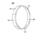
- FIG. 1 is a schematic diagram of a ring electronic device according to an embodiment of the present disclosure
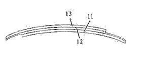
- FIG. 2 is a schematic structural diagram of a curved surface segment according to an embodiment of the present disclosure
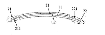
- FIG. 3 is a schematic diagram of a first connecting portion and a second connecting portion on a curved surface segment according to an embodiment of the present disclosure
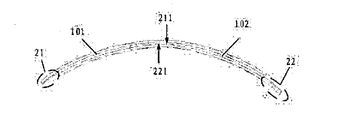
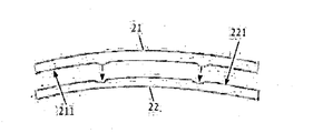
- FIG. 4 is a schematic diagram of connection of two curved segments according to an embodiment of the present disclosure.
- FIG. 5 is a schematic diagram of a first connecting portion and a second connecting portion according to an embodiment of the present disclosure
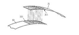
- FIG. 6 is a schematic diagram of another first connecting portion and a second connecting portion according to an embodiment of the present disclosure.
- Figure 7 is a schematic view showing the connection of the two connecting portions shown in Figure 6;
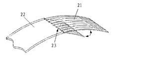
- FIG. 8 is a schematic diagram of a hinge of a first connecting portion and a second connecting portion according to an embodiment of the present disclosure.
- FIG. 1 An embodiment of the present disclosure provides a toroidal electronic device 100, as shown in FIG. 1, including at least two curved segments that can be connected in a ring shape, and FIG. 1 includes five curved segments as an example, that is, a curved segment 101 and a curved segment. 102. A curved segment 103, a curved segment 104, and a curved segment 105. As shown in FIG. 2, each curved segment includes a processing chip 12 and a display panel 13. For example, each curved segment may also include a power source 11. It is also possible to have only one surface segment including the power source.
- each of the curved segments includes a power source
- the display panel 13 is located on the outer surface of the curved segment, and the processing chip 12 is respectively connected to the power source 11 and the display panel 13, and the display panel 13 is configured to display an image under the driving of the processing chip 12.
- each curved surface segment is not limited to those shown in FIG. 2, and the present disclosure is only described by taking the example shown in FIG. 2 as an example.
- a ring-shaped electronic device is taken as an example of a smart wristband.
- each curved segment can display different content or be used to implement different functions.
- the curved segment 101 can be used only for display time
- the curved segment 102 can be used only for displaying weather
- the curved segment 103 can be used only for display position
- the curved segment 104 can be used only for monitoring body temperature
- the curved segment 105 can be It is only used for step counting. That is, each surface segment can perform a function independently. Even if one of the curved segments is damaged, it will not affect the use of other curved segments. Users can also repair or re-detach the damaged surface segments only.
- the annular electronic device provided by the embodiment of the present disclosure includes at least two curved segments connectable in a ring shape. Since each curved segment includes a processing chip and a display panel, the display panel can display an image under the driving of the processing chip. Therefore, in the embodiment of the present disclosure, each curved surface segment is a separate display unit, and any curved surface segment can be removed or replaced with a new curved surface segment when the battery is not frequently replaced. Ensure the use of ring electronic devices.
- each of the curved segments includes a processing chip and a display panel, each including a power supply, a processing chip, and a display panel.
- the battery can be used to provide electrical signals to the display panel and the processing chip, and the display panel can display an image under the driving of the processing chip. Therefore, in the embodiment of the present disclosure, each curved surface segment is a separate display unit, and any curved surface segment can be used without being used. Remove or replace a new curved segment to ensure the use of ring electronics.
- At least two curved segments are detachably connected.
- the number of curved segments and the functions of the curved segments can be selected according to the user's needs or the size of the user's wrist, thereby forming a ring-shaped electronic device that can realize different functions, and the user can customize the service according to his own needs.
- the power source 11, the processing chip 12, and the display panel 13 are stacked.
- the display panel 13 is located on the outer surface of the curved section for display, and the position of the processing chip and the power source may not be specifically limited.
- the processing chip 12 is located between the power source 11 and the display panel 13, so that the processing chip 12 and the display panel 13 are connected, and the display panel is controlled for display.
- the curved section includes a body and first and second connecting portions 21 and 22 at both ends of the body.
- the two curved segments are connected at a joint position, and the first connecting portion 21 of one curved segment is connected to the second connecting portion 22 of the other curved segment, that is, the two curved segments are connected end to end.
- the first connection portion may be a USB-like socket
- the second connection portion may be a USB-like connector such that each curved segment includes a socket and a plug that are freely connectable.
- At least two curved segments are detachably connected, and the first connecting end and the second connecting end of one of the curved segments may be USB-like connectors, and the first connecting ends of the other two curved segments connected thereto are
- the second connecting end may be similar to the USB socket, and the first connecting end or the second connecting end of one curved segment may be connected with the first connecting end or the second connecting end of the other curved segment, so that multiple curved segments can also be realized. Removable connection.
- any two curved segments may be connected, and the curved segment has no connection requirement, and only needs to be satisfied. It can be used as a requirement, and it is more convenient to select surface segments.
- the display panel 13 in the curved section is located at a corresponding position of the main body (a portion between the first connecting portion and the second connection) and the first connecting portion 21.
- the processing chip is located at a corresponding position of the main body and the first connecting portion and the second connecting portion At the office.
- the power source is located at a corresponding position of the main body and the second connecting portion.
- the display panel 13 is located at the corresponding position of the main body and the first connecting portion 21, and the display panel has a larger display area in each display segment. Therefore, the display panel in the two curved segments is located at the joint of the two curved segments and the connecting positions of the two curved segments, and the display panel has a larger display area, which is advantageous for displaying more or displaying a larger APP.
- the thickness of the two curved segments at the joint position is the same as the thickness of the body of the two curved segments, that is, at the joint position of the two curved segments,
- the sum of the thicknesses of the first connecting portion and the second connecting portion is equal to the thickness of the body.
- the thickness of the first connecting portion 21 and the second connecting portion 22 may be respectively half of the thickness of the main body, and the schematic diagrams of the two curved segments are connected as shown in FIG. 4, and two curved segments are shown.
- the thickness at the joint location is the same as the thickness of the body of the two curved segments.
- the thickness of the two curved segments at the joint position is the same as the thickness of the two curved segments, and is not limited to the above embodiment, and any one of the first connecting portion and the second connecting portion may be selectively thinned.
- the sum of the thicknesses of the first connecting portion and the second connecting portion is equal to the thickness of the main body at the connecting position of the two curved segments, and the embodiment of the present disclosure only uses FIG. 3 .
- the example shown in FIG. 4 will be described.
- the inner surface 211 of the first connecting portion 21 is a connecting surface; the outer surface 221 of the second connecting portion 22 is a connecting surface; the two curved segments are at the connecting position.
- the curved section 101 and the curved section 102 are connected as an example, and the outer connecting surface 211 of one curved section (ie, the curved section 102) and the outer connecting surface 221 of the other curved section (ie, the curved section 101) are shown. Contact, magnetically attached.
- the display area of the ring-shaped electronic device can be maximized. For example, after the inner surface of the first connecting portion and the outer surface of the second connecting portion are magnetically attracted, then the display panel is located at a corresponding position of the body and the joint, then The display area of the display panel is large. Moreover, for example, in the case where the display panel has no border, the display area of the ring electronic device is substantially equal to the area of the outer surface of the ring electronic device.
- connection of the two connecting segments is realized by magnetic adsorption, which makes the connection convenient and the operation simple. Since the first connecting end and the second connecting end are in surface contact, the area of magnetic adsorption can be further increased, which is advantageous for the fastening of the connection.
- the inner surface of the first connecting portion is provided with a processing chip a first interface
- the second surface of the second connecting portion is provided with a second interface connected to the processing chip
- the two curved segments are at the connecting position
- the first surface of the first connecting portion of the curved surface is first
- the interface is coupled to the second interface on the outer surface of the second connection of the other curved segment such that the processing chips of the two curved segments that are connected to each other are connected.
- the processing chip is located at a corresponding position of the main body and the first connecting portion and the second connecting portion, and the inner surface of the first connecting portion is provided with a first interface connected to the processing chip, and an outer surface of the second connecting portion A second interface connected to the processing chip is disposed, which is more advantageous for the connection of the processing chips of the two curved segments.
- the processing chip connection of the curved segments can be implemented by hardware or firmware. Of course, it can also be implemented by software. For example, software for implementing the connection is installed in each surface segment, and the two curved segments can realize information interaction through the first interface and the second interface, thereby controlling the combination of functions between the curved segments, and controlling the surfaces through software. The display of the segment.
- the inner surface 211 of the first connecting portion 21 is provided with a first protrusion, and the outer surface 221 of the second connecting portion 22 is provided with a second groove;
- the first projection of the inner surface 211 of the first joint portion 21 of one of the curved segments is fitted with the second recess of the outer surface 221 of the second joint portion 22 of the other curved segment.
- a projection and a groove are provided on the inner surface of the connecting portion, and the relative sliding of the first connecting portion and the second connecting portion can be prevented after the projection and the groove are fitted.
- the inner surface of the first connecting portion is further provided with a first groove
- the outer surface of the second connecting portion is further provided with a second protrusion
- the two curved segments are at the connecting position, one of the curved segments
- the first groove is fitted to the second protrusion of the other curved segment. That is, as shown in FIG. 6 and FIG. 7, the inner surface 211 of the first connecting portion 21 and the outer surface 221 of the second connecting portion 22 are respectively provided with protrusions and grooves, and the protrusions and the second connecting portion of the first connection 21
- the groove of the second connecting portion 21 is fitted into the projection of the second connecting portion 22 so that the projection of the first connecting portion 21 and the recess of the second connecting portion 22 cannot be fitted. In the case of the action, the groove of the first connecting portion 21 and the projection of the second connecting portion 22 are fitted.
- At least two curved segments are hinged.
- the two curved segments can be hinged by the connecting shaft 23, so that the two curved segments (ie, the first connecting portion 21 and the second connecting portion 22 shown in FIG. 8) can be along the connecting shaft 23 Perform a certain angle of rotation to adjust the connection of the curved segments to form a ring.
- the hinge In the embodiment of the present invention, the two curved segments can also be connected by a snap connection, a screw connection or the like.
- the two curved surface segments can be hinged in various embodiments.
- the embodiment of the present disclosure and the drawings are only exemplified by the connecting shaft hinge shown in FIG. 8 . Be explained.
- the display panel is a flexible display panel.
- the display panel is a flexible display panel, which is more advantageous for adjusting the curved section and adjusting the shape of the ring.
- the total length of the ring display device is also not limited, and the user can set according to personal preference.
- the length of the curved section ranges from 50 mm to 60 mm.
- the length of the first connecting portion and the second connecting portion ranges from 10 mm to 12 mm.
- the width of the curved section ranges from 20mm to 50mm.
Landscapes
- Engineering & Computer Science (AREA)
- Theoretical Computer Science (AREA)
- Computer Hardware Design (AREA)
- Physics & Mathematics (AREA)
- General Physics & Mathematics (AREA)
- General Engineering & Computer Science (AREA)
- Human Computer Interaction (AREA)
- Devices For Indicating Variable Information By Combining Individual Elements (AREA)
Abstract
Description
Claims (19)
- 一种环形电子设备,包括连接后呈环形的至少两个曲面段;每个所述曲面段包括处理芯片以及显示面板,其中,所述显示面板位于所述曲面段的外表面,所述处理芯片与所述显示面板连接。
- 根据权利要求1所述的环形电子设备,其中,每个所述曲面段还包括电源,所述处理芯片还与所述电源连接。
- 根据权利要求1或2所述的环形电子设备,其中,所述至少两个曲面段可拆卸连接。
- 根据权利要求1-3任一所述的环形电子设备,其中,每个所述曲面段中,所述处理芯片以及显示面板层叠设置。
- 根据权利要求2-4任一所述的环形电子设备,其中,每个所述曲面段中,所述电源、处理芯片以及显示面板层叠设置。
- 根据权利要求2-5任一所述的环形电子设备,其中,所述处理芯片位于所述电源和所述显示面板之间。
- 根据权利要求1-6任一所述的环形电子设备,其中,所述曲面段包括主体以及位于所述主体两端的第一连接部和第二连接部;两个曲面段在连接位置处,其中一个曲面段的第一连接部与另一个曲面段的第二连接部连接。
- 根据权利要求7所述的环形电子设备,其中,所述第一连接部的内表面为连接面;所述第二连接部的外表面为连接面;两个曲面段在连接位置处,其中一个曲面段的第一连接面与另外一个曲面段的第二连接面相接触并连接。
- 根据权利要求8所述的环形电子设备,其中,两个曲面段在连接位置处,其中一个曲面段的第一连接面与另外一个曲面段的第二连接面以磁性吸附方式连接。
- 根据权利要求7-9任一所述的环形电子设备,其中,所述曲面段的显示面板位于所述主体以及所述第一连接部的对应位置处;和/或所述曲面段的处理芯片位于所述主体以及所述第一连接部和第二连接部的对应位置处;和/或所述曲面段的电源位于所述主体以及所述第二连接部的对应位置处。
- 根据权利要求7-10任一所述的环形电子设备,其中,所述第一连接部的内表面上设置有与所述处理芯片连接的第一接口,所述第二连接部的外表面上设置有与所述处理芯片连接的第二接口;两个曲面段在连接位置处,其中一个曲面段的第一连接部的内表面上的第一接口与另外一个曲面段的第二连接部的外表面上的第二接口连接,从而使得相互连接的两个曲面段的处理芯片连接。
- 根据权利要求7-11任一所述的环形电子设备,其中,所述第一连接部的内表面设置有第一凸起,所述第二连接部的外表面设置有第二凹槽;两个曲面段在连接位置处,其中一个曲面段的第一凸起与另外一个曲面段的第二凹槽嵌合。
- 根据权利要求12所述的环形电子设备,其中,所述第一连接部的内表面还设置有第一凹槽,所述第二连接部的外表面还设置有第二凸起;两个曲面段在连接位置处,其中一个曲面段的第一凹槽与另外一个曲面段的第二凸起嵌合。
- 根据权利要求7-13任一所述的环形电子设备,其中,在两个曲面段的连接位置处,所述第一连接部和所述第二连接部的厚度之和等于所述主体的厚度。
- 根据权利要求1-14任一所述的环形电子设备,其中,所述至少两个曲面段铰接。
- 根据权利要求1-15任一所述的环形电子设备,其中,所述显示面包板为柔性显示面板。
- 根据权利要求1-16任一所述的环形电子设备,其中,所述曲面段的长度范围为50mm-60mm。
- 根据权利要求1-17任一所述的环形电子设备,其中,所述曲面段的宽度范围为20mm-50mm。
- 根据权利要求7-18任一所述的环形电子设备,其中,所述第一连接部和所述第二连接部的长度范围为10mm-12mm。
Priority Applications (1)
| Application Number | Priority Date | Filing Date | Title |
|---|---|---|---|
| US15/522,385 US20180084872A1 (en) | 2016-01-18 | 2016-08-25 | Annular electronic device |
Applications Claiming Priority (2)
| Application Number | Priority Date | Filing Date | Title |
|---|---|---|---|
| CN201610031156.5A CN105661764B (zh) | 2016-01-18 | 2016-01-18 | 一种环形电子设备 |
| CN201610031156.5 | 2016-01-18 |
Publications (1)
| Publication Number | Publication Date |
|---|---|
| WO2017124746A1 true WO2017124746A1 (zh) | 2017-07-27 |
Family
ID=56301261
Family Applications (1)
| Application Number | Title | Priority Date | Filing Date |
|---|---|---|---|
| PCT/CN2016/096728 Ceased WO2017124746A1 (zh) | 2016-01-18 | 2016-08-25 | 环形电子设备 |
Country Status (3)
| Country | Link |
|---|---|
| US (1) | US20180084872A1 (zh) |
| CN (1) | CN105661764B (zh) |
| WO (1) | WO2017124746A1 (zh) |
Families Citing this family (4)
| Publication number | Priority date | Publication date | Assignee | Title |
|---|---|---|---|---|
| CN105661764B (zh) * | 2016-01-18 | 2018-11-30 | 京东方科技集团股份有限公司 | 一种环形电子设备 |
| CN106406497B (zh) * | 2016-09-20 | 2019-04-16 | 广州视源电子科技股份有限公司 | 一种智能耳环 |
| CN107992977A (zh) * | 2017-12-19 | 2018-05-04 | 合肥智灵机器人有限公司 | 一种仓储拣货搬运系统及方法 |
| KR102348596B1 (ko) * | 2020-02-07 | 2022-01-07 | 주식회사 토비스 | 디스플레이패널의 형상 가변장치 및 이를 구비한 곡면 디스플레이장치 |
Citations (6)
| Publication number | Priority date | Publication date | Assignee | Title |
|---|---|---|---|---|
| CN103393260A (zh) * | 2013-08-20 | 2013-11-20 | 百度在线网络技术(北京)有限公司 | 智能手环 |
| CN104020879A (zh) * | 2014-05-23 | 2014-09-03 | 京东方科技集团股份有限公司 | 一种柔性显示装置 |
| CN104382304A (zh) * | 2014-11-24 | 2015-03-04 | 侨健新能源科技(苏州)有限公司 | 一种紧贴智能手表 |
| JP2015130650A (ja) * | 2013-11-15 | 2015-07-16 | 株式会社半導体エネルギー研究所 | 電子機器 |
| JP2015226204A (ja) * | 2014-05-28 | 2015-12-14 | 京セラ株式会社 | 携帯端末 |
| CN105661764A (zh) * | 2016-01-18 | 2016-06-15 | 京东方科技集团股份有限公司 | 一种环形电子设备 |
Family Cites Families (14)
| Publication number | Priority date | Publication date | Assignee | Title |
|---|---|---|---|---|
| GB0004688D0 (en) * | 2000-02-28 | 2000-04-19 | Radley Smith Philip J | Bracelet |
| CN2478198Y (zh) * | 2001-02-13 | 2002-02-20 | 四川托普集团科技发展有限责任公司 | 曲面显示屏 |
| CN1402118A (zh) * | 2001-08-15 | 2003-03-12 | 无敌科技股份有限公司 | 具有可串接便携式电子装置的显示屏单体装置 |
| US7320194B2 (en) * | 2004-06-01 | 2008-01-22 | Precision Dynamics Corporation | Adhesive wristband without removable release liner |
| CN100468488C (zh) * | 2006-12-05 | 2009-03-11 | 夏志清 | 圆弧形led显示屏 |
| US8988349B2 (en) * | 2012-02-28 | 2015-03-24 | Google Technology Holdings LLC | Methods and apparatuses for operating a display in an electronic device |
| CN203259809U (zh) * | 2013-04-10 | 2013-10-30 | 深圳市立德通讯器材有限公司 | 超薄智能手表 |
| WO2015005552A1 (en) * | 2013-07-08 | 2015-01-15 | Samsung Electronics Co., Ltd. | Prism sheet member and multivision display apparatus having the same |
| CN203456045U (zh) * | 2013-09-07 | 2014-02-26 | 向火平 | 一种组合式显示屏 |
| EP3087560B9 (en) * | 2013-12-24 | 2021-08-11 | Flexterra, Inc. | Support structures for a flexible electronic component |
| CN105242799B (zh) * | 2014-06-12 | 2018-08-21 | 宸鸿科技(厦门)有限公司 | 曲面触控显示模组及可穿戴设备 |
| CN204242526U (zh) * | 2014-12-12 | 2015-04-01 | 京东方科技集团股份有限公司 | 一种环形多面显示器件 |
| CN104576965B (zh) * | 2014-12-29 | 2017-02-22 | 北京维信诺科技有限公司 | 一种可首尾电连接的柔性显示装置及其制备方法 |
| CN204271144U (zh) * | 2014-12-29 | 2015-04-15 | 北京维信诺科技有限公司 | 一种柔性显示装置 |
-
2016
- 2016-01-18 CN CN201610031156.5A patent/CN105661764B/zh active Active
- 2016-08-25 WO PCT/CN2016/096728 patent/WO2017124746A1/zh not_active Ceased
- 2016-08-25 US US15/522,385 patent/US20180084872A1/en not_active Abandoned
Patent Citations (6)
| Publication number | Priority date | Publication date | Assignee | Title |
|---|---|---|---|---|
| CN103393260A (zh) * | 2013-08-20 | 2013-11-20 | 百度在线网络技术(北京)有限公司 | 智能手环 |
| JP2015130650A (ja) * | 2013-11-15 | 2015-07-16 | 株式会社半導体エネルギー研究所 | 電子機器 |
| CN104020879A (zh) * | 2014-05-23 | 2014-09-03 | 京东方科技集团股份有限公司 | 一种柔性显示装置 |
| JP2015226204A (ja) * | 2014-05-28 | 2015-12-14 | 京セラ株式会社 | 携帯端末 |
| CN104382304A (zh) * | 2014-11-24 | 2015-03-04 | 侨健新能源科技(苏州)有限公司 | 一种紧贴智能手表 |
| CN105661764A (zh) * | 2016-01-18 | 2016-06-15 | 京东方科技集团股份有限公司 | 一种环形电子设备 |
Also Published As
| Publication number | Publication date |
|---|---|
| CN105661764A (zh) | 2016-06-15 |
| US20180084872A1 (en) | 2018-03-29 |
| CN105661764B (zh) | 2018-11-30 |
Similar Documents
| Publication | Publication Date | Title |
|---|---|---|
| US10599181B2 (en) | Auxiliary electronic device attachable to a wearable electronic device | |
| WO2017124746A1 (zh) | 环形电子设备 | |
| CN104020879B (zh) | 一种柔性显示装置 | |
| US20170147033A1 (en) | Wearable Ring Control Device | |
| CN204467157U (zh) | 表带及适用于智能手表的传输装置 | |
| CN111948933A (zh) | 可穿戴设备 | |
| TW201636822A (zh) | 保護套及應用該保護套的可攜式電子裝置組件 | |
| CN221690289U (zh) | 一种智能戒指的组装结构 | |
| CN101072245A (zh) | 表式移动终端 | |
| CN206197235U (zh) | 可自动调节粗细手指环 | |
| CN204483295U (zh) | 一种方便佩戴和取下的智能手环 | |
| CN104865823A (zh) | 智能手表 | |
| KR101678642B1 (ko) | 스마트 안경 및 이를 포함하는 손목시계 | |
| CN204301318U (zh) | 一种可穿戴的热水器遥控器 | |
| KR20120006596A (ko) | 정전 용량 방식의 터치 단말기에 구비된 도전성 터치펜 | |
| CN205902918U (zh) | 一种高精度导航支付手环 | |
| CN206565433U (zh) | 一种智能指环 | |
| CN105468207B (zh) | 穿戴式电子装置及游标控制装置 | |
| WO2017015830A1 (zh) | 一种联屏式太阳能智能手环 | |
| CN105996330B (zh) | 一种高精度导航支付手环 | |
| CN220156515U (zh) | 一种随身控制终端 | |
| CN105892725B (zh) | 一种可万向调节感光头方向的无线指环式鼠标 | |
| CN205540560U (zh) | 一种基于蓝牙控制的电脑操作手套 | |
| CN209498825U (zh) | 一种智能戒指 | |
| CN206534211U (zh) | 一种伸缩数据线智能手环 |
Legal Events
| Date | Code | Title | Description |
|---|---|---|---|
| WWE | Wipo information: entry into national phase |
Ref document number: 15522385 Country of ref document: US |
|
| 121 | Ep: the epo has been informed by wipo that ep was designated in this application |
Ref document number: 16886006 Country of ref document: EP Kind code of ref document: A1 |
|
| NENP | Non-entry into the national phase |
Ref country code: DE |
|
| 122 | Ep: pct application non-entry in european phase |
Ref document number: 16886006 Country of ref document: EP Kind code of ref document: A1 |
|
| 122 | Ep: pct application non-entry in european phase |
Ref document number: 16886006 Country of ref document: EP Kind code of ref document: A1 |