WO2017123015A1 - 고내화 케이블 - Google Patents
고내화 케이블 Download PDFInfo
- Publication number
- WO2017123015A1 WO2017123015A1 PCT/KR2017/000399 KR2017000399W WO2017123015A1 WO 2017123015 A1 WO2017123015 A1 WO 2017123015A1 KR 2017000399 W KR2017000399 W KR 2017000399W WO 2017123015 A1 WO2017123015 A1 WO 2017123015A1
- Authority
- WO
- WIPO (PCT)
- Prior art keywords
- layer
- gap
- thermal barrier
- fire
- cable
- Prior art date
- Legal status (The legal status is an assumption and is not a legal conclusion. Google has not performed a legal analysis and makes no representation as to the accuracy of the status listed.)
- Ceased
Links
Images




Classifications
-
- H—ELECTRICITY
- H01—ELECTRIC ELEMENTS
- H01B—CABLES; CONDUCTORS; INSULATORS; SELECTION OF MATERIALS FOR THEIR CONDUCTIVE, INSULATING OR DIELECTRIC PROPERTIES
- H01B7/00—Insulated conductors or cables characterised by their form
- H01B7/17—Protection against damage caused by external factors, e.g. sheaths or armouring
- H01B7/29—Protection against damage caused by extremes of temperature or by flame
-
- H—ELECTRICITY
- H01—ELECTRIC ELEMENTS
- H01B—CABLES; CONDUCTORS; INSULATORS; SELECTION OF MATERIALS FOR THEIR CONDUCTIVE, INSULATING OR DIELECTRIC PROPERTIES
- H01B3/00—Insulators or insulating bodies characterised by the insulating materials; Selection of materials for their insulating or dielectric properties
- H01B3/02—Insulators or insulating bodies characterised by the insulating materials; Selection of materials for their insulating or dielectric properties mainly consisting of inorganic substances
- H01B3/04—Insulators or insulating bodies characterised by the insulating materials; Selection of materials for their insulating or dielectric properties mainly consisting of inorganic substances mica
-
- H—ELECTRICITY
- H01—ELECTRIC ELEMENTS
- H01B—CABLES; CONDUCTORS; INSULATORS; SELECTION OF MATERIALS FOR THEIR CONDUCTIVE, INSULATING OR DIELECTRIC PROPERTIES
- H01B3/00—Insulators or insulating bodies characterised by the insulating materials; Selection of materials for their insulating or dielectric properties
- H01B3/02—Insulators or insulating bodies characterised by the insulating materials; Selection of materials for their insulating or dielectric properties mainly consisting of inorganic substances
- H01B3/08—Insulators or insulating bodies characterised by the insulating materials; Selection of materials for their insulating or dielectric properties mainly consisting of inorganic substances quartz; glass; glass wool; slag wool; vitreous enamels
-
- H—ELECTRICITY
- H01—ELECTRIC ELEMENTS
- H01B—CABLES; CONDUCTORS; INSULATORS; SELECTION OF MATERIALS FOR THEIR CONDUCTIVE, INSULATING OR DIELECTRIC PROPERTIES
- H01B3/00—Insulators or insulating bodies characterised by the insulating materials; Selection of materials for their insulating or dielectric properties
- H01B3/18—Insulators or insulating bodies characterised by the insulating materials; Selection of materials for their insulating or dielectric properties mainly consisting of organic substances
- H01B3/28—Insulators or insulating bodies characterised by the insulating materials; Selection of materials for their insulating or dielectric properties mainly consisting of organic substances natural or synthetic rubbers
-
- H—ELECTRICITY
- H01—ELECTRIC ELEMENTS
- H01B—CABLES; CONDUCTORS; INSULATORS; SELECTION OF MATERIALS FOR THEIR CONDUCTIVE, INSULATING OR DIELECTRIC PROPERTIES
- H01B3/00—Insulators or insulating bodies characterised by the insulating materials; Selection of materials for their insulating or dielectric properties
- H01B3/18—Insulators or insulating bodies characterised by the insulating materials; Selection of materials for their insulating or dielectric properties mainly consisting of organic substances
- H01B3/30—Insulators or insulating bodies characterised by the insulating materials; Selection of materials for their insulating or dielectric properties mainly consisting of organic substances plastics; resins; waxes
-
- H—ELECTRICITY
- H01—ELECTRIC ELEMENTS
- H01B—CABLES; CONDUCTORS; INSULATORS; SELECTION OF MATERIALS FOR THEIR CONDUCTIVE, INSULATING OR DIELECTRIC PROPERTIES
- H01B3/00—Insulators or insulating bodies characterised by the insulating materials; Selection of materials for their insulating or dielectric properties
- H01B3/18—Insulators or insulating bodies characterised by the insulating materials; Selection of materials for their insulating or dielectric properties mainly consisting of organic substances
- H01B3/30—Insulators or insulating bodies characterised by the insulating materials; Selection of materials for their insulating or dielectric properties mainly consisting of organic substances plastics; resins; waxes
- H01B3/46—Insulators or insulating bodies characterised by the insulating materials; Selection of materials for their insulating or dielectric properties mainly consisting of organic substances plastics; resins; waxes silicones
-
- H—ELECTRICITY
- H01—ELECTRIC ELEMENTS
- H01B—CABLES; CONDUCTORS; INSULATORS; SELECTION OF MATERIALS FOR THEIR CONDUCTIVE, INSULATING OR DIELECTRIC PROPERTIES
- H01B7/00—Insulated conductors or cables characterised by their form
- H01B7/02—Disposition of insulation
-
- H—ELECTRICITY
- H01—ELECTRIC ELEMENTS
- H01B—CABLES; CONDUCTORS; INSULATORS; SELECTION OF MATERIALS FOR THEIR CONDUCTIVE, INSULATING OR DIELECTRIC PROPERTIES
- H01B7/00—Insulated conductors or cables characterised by their form
- H01B7/02—Disposition of insulation
- H01B7/0208—Cables with several layers of insulating material
- H01B7/0225—Three or more layers
-
- H—ELECTRICITY
- H01—ELECTRIC ELEMENTS
- H01B—CABLES; CONDUCTORS; INSULATORS; SELECTION OF MATERIALS FOR THEIR CONDUCTIVE, INSULATING OR DIELECTRIC PROPERTIES
- H01B7/00—Insulated conductors or cables characterised by their form
- H01B7/02—Disposition of insulation
- H01B7/0241—Disposition of insulation comprising one or more helical wrapped layers of insulation
-
- H—ELECTRICITY
- H01—ELECTRIC ELEMENTS
- H01B—CABLES; CONDUCTORS; INSULATORS; SELECTION OF MATERIALS FOR THEIR CONDUCTIVE, INSULATING OR DIELECTRIC PROPERTIES
- H01B7/00—Insulated conductors or cables characterised by their form
- H01B7/02—Disposition of insulation
- H01B7/0266—Disposition of insulation comprising one or more braided layers of insulation
-
- H—ELECTRICITY
- H01—ELECTRIC ELEMENTS
- H01B—CABLES; CONDUCTORS; INSULATORS; SELECTION OF MATERIALS FOR THEIR CONDUCTIVE, INSULATING OR DIELECTRIC PROPERTIES
- H01B7/00—Insulated conductors or cables characterised by their form
- H01B7/17—Protection against damage caused by external factors, e.g. sheaths or armouring
- H01B7/29—Protection against damage caused by extremes of temperature or by flame
- H01B7/292—Protection against damage caused by extremes of temperature or by flame using material resistant to heat
-
- H—ELECTRICITY
- H01—ELECTRIC ELEMENTS
- H01B—CABLES; CONDUCTORS; INSULATORS; SELECTION OF MATERIALS FOR THEIR CONDUCTIVE, INSULATING OR DIELECTRIC PROPERTIES
- H01B7/00—Insulated conductors or cables characterised by their form
- H01B7/17—Protection against damage caused by external factors, e.g. sheaths or armouring
- H01B7/29—Protection against damage caused by extremes of temperature or by flame
- H01B7/295—Protection against damage caused by extremes of temperature or by flame using material resistant to flame
Definitions
- the present invention relates to a high fire-resistant cable, and more particularly, to exhibit a fire-resistant performance that satisfies international standards in the event of a high-temperature fire, and to improve the workability by reducing the outer diameter and weight and ensuring bending performance It is about fireproof cable.
- the level of demand for fire resistance is increasing gradually.
- cable products used in land / ocean plants such as offshore oil drilling facilities and onshore refineries require higher fire resistance.
- a cable is required for the emergency power supply of core facilities, fire alarm and sprinkler, and operation of fire / disaster prevention system for minimum time to escape and evacuate personnel in a high temperature environment.
- the medium voltage cable refers to a cable of MV class (Medium Voltage) or HV class (High Voltage) of 6 kV or more, and also referred to as a medium voltage cable.
- the insulating layer serves to prevent electric current from flowing out of the cable by insulating the inner conductor and the outside, and the inner semiconducting layer uniforms the electric charge distribution on the surface of the conductor to reduce electric field concentration inside the cable, and the conductor and the insulator The gap between the gaps is filled to minimize insulation deterioration due to ionization.
- the outer semiconducting layer equalizes electrical stress in the insulator and minimizes external corona.
- Embodiments of the present invention are intended to exhibit a fire resistance performance that satisfies international standards even in the event of a high temperature fire due to hydrocarbon-based compounds constituting petroleum and coal tar.
- the thermal insulation layer ensures sufficient insulation performance so that the insulation layer performs an insulation function for a long time, thereby further maintaining the electric power of the cable.
- the conductor An insulation layer formed outside the conductor; A bedding layer formed outside the insulating layer; An inner sheath layer formed outside the bedding layer; An internal semiconducting layer provided between the conductor and the insulating layer; An outer semiconducting layer provided between the insulating layer and the bedding layer; A braided layer provided between the bedding layer and the inner sheath layer; And a heat shield layer formed outside the inner sheath layer and having a heat insulating performance in the event of a fire.
- the thermal barrier layer may include at least one first gap formed to have a predetermined thickness in a radial direction along an inner circumference of the thermal barrier layer.
- the thermal barrier layer may be formed to have a thickness smaller than the first gap, and may further include at least one second gap positioned between adjacent first gaps.
- the width of the second gap may correspond to a gap between the adjacent first gaps.
- the thermal barrier layer may have a thickness of 6 mm to 14 mm.
- the number of first gaps and the second gaps may be 2: 1.
- the thickness of the first gap may be 2 mm to 5 mm.
- the second gap may have a thickness of about 0.5 mm to about 2 mm.
- the thermal barrier layer may be made of any one of rubber, EVA (Ethylene Vinyl Acetate) foam, or XLPO (Crosslinked Polyolefin).
- the thermal barrier layer may further comprise silica or mica powder.
- the bedding layer may be made of the same material as the thermal barrier layer but may include crosslinking characteristics.
- the high refractory cable according to the present invention may further comprise an insulating tape wound around the outside of the thermal barrier layer.
- the insulating tape may be any one of a mica tape, a silica tape, a glass tape.
- the insulation tape may be configured to wind one or two sheets.
- the width overlap ratio of the insulating tape may be 5% to 50%.
- the high fireproof cable according to the present invention may further comprise an outermost sheath layer formed on the outer side of the insulating tape.
- the thermal barrier layer may be provided at a predetermined interval along the outer circumference of the inner sheath layer, and may include a plurality of first teeth formed to extend toward the inner sheath layer to contact the inner sheath layer.
- the thermal barrier layer may further include a second tooth extending between the first tooth toward the inner sheath layer and forming a predetermined gap between the inner tooth layer and the inner sheath layer.
- the thermal barrier layer includes a plurality of gaps formed to face each other along the inner circumference and the outer circumference of the thermal barrier layer, and a plurality of teeth extending from the gap side to the inner and outer sides of the thermal barrier layer, respectively,
- the gap and the teeth formed on both sides of the gap may be configured to form an H-beam.
- Embodiments of the present invention can exhibit a fire resistance performance that satisfies international standards even in the event of a high temperature fire caused by hydrocarbon-based compounds constituting petroleum and coal tar.
- the thermal insulation layer ensures sufficient insulation performance so that the insulation layer can perform insulation function for a long time to further maintain the electric power of the cable.
- FIG. 1 is a perspective view of a high fire resistant cable according to a first embodiment of the present invention
- FIG. 2 is a cross-sectional view of a high fire resistant cable according to a first embodiment of the present invention.
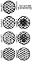
- FIG. 3 is an image comparing heat transfer analysis results of a high fireproof cable according to a first embodiment of the present invention and its comparative examples
- FIG. 4 is a graph showing the insulation maximum temperature of a high fireproof cable according to a first embodiment of the present invention and its comparative examples
- FIG. 5 is a graph comparing a change in insulation temperature with time of a high fireproof cable according to a first embodiment of the present invention and comparative examples thereof;
- FIG. 6 is a cutaway perspective view of a high fireproof cable according to a second embodiment of the present invention.
- FIG. 7 is a cross-sectional view of a high fire resistant cable according to a second embodiment of the present invention.
- FIG. 8 is a cross-sectional view of a high fireproof cable according to a modification of the second embodiment of the present invention.
- Figure 9 is an image comparing the heat transfer analysis results of the high-fireproof cable according to the second embodiment of the present invention and the cable of the existing structure
- FIG. 11 is a cross-sectional view of a high fire resistant cable according to a third embodiment of the present invention.
- FIG. 1 is a cutaway perspective view of a high refractory cable according to a first embodiment of the present invention
- Figure 2 is a cross-sectional view of a high refractory cable according to a first embodiment of the present invention.
- the high fire-resistant cable 100 includes a conductor 110, an insulating layer 130 formed outside the conductor 110, and the insulation.
- the conductor 110 may be a Class 2 or Class 5 conductor that satisfies the IEC 60228 standard.
- the inner semiconducting layer formed on the outside of the conductor 110 may be formed by winding the semiconducting tape 120 or through the semiconducting extrusion layer 122 extruded with the semiconducting compound, and simultaneously applying them to the composite layer 120. And 122).
- the inner semiconducting layer is composed of the composite layers 120 and 122 by simultaneously applying the semiconducting tape 120 and the semiconducting extrusion layer 122 as shown in FIGS. 1 and 2.
- the inner semiconducting layer uniforms the charge distribution on the surface of the conductor to alleviate electric field concentration inside the cable, and fills a gap between the conductor 110 and the insulating layer 130, which will be described later. It can play a role of minimizing deterioration.
- the insulating layer 130 is made of a material having insulating and impact resistance characteristics, and serves to cover and protect the conductor 110 and to insulate the conductor 110 and the outside from inside to prevent current from flowing out of the cable. Perform.
- the insulating layer 130 is made of silicon rubber, cross-linked polyethylene (XLPE), cross-linked polyollefin (XLPO), ethylene-propylene rubber (EPR), high density ethylene It may be made of polymers such as high ethylene-propylene rubber (EPR), polyvinyl chloride (PVC), and mixtures thereof.
- the outer semiconducting layer 140 formed on the outside of the insulating layer 130 is formed by winding a semiconducting compound by extrusion or semiconducting tape, and applying them simultaneously to form a composite layer.
- the external semiconducting layer 140 serves to equalize the electrical stress in the insulating layer 130 and minimize the external corona.
- the shielding layer 150 formed outside the outer semiconducting layer 140 may be formed of a material such as copper, aluminum, a copper alloy, an aluminum alloy, or the like, and may be formed in a metal tape form or a metal braided form.
- the shielding layer 150 should be in contact with the outer semiconducting layer 140, because if the shielding layer 150 and the outer semiconducting layer 150 are not in contact with each other, a problem arises in that the ground must be separately provided. to be.
- the conductor 110 has a three-phase structure having three conductors, but is not limited thereto.
- a single-phase structure, a pair, or a quad structure having only one conductor 110 may be provided. It is also possible to apply.
- the three conductors 110 form a federated structure, and the joining tape (not shown) can be wound around them so that the federated structure is not loosened.
- the bedding layer 172 may be provided in an extruded form to the outside of the associated structure.
- the bedding layer 172 may be made of the same material as the material of the thermal barrier layer 180 to be described later, which will be described later.
- the braided layer 174 is formed outside the bedding layer 172.
- the braided layer 174 may be formed of a metal material such as copper, aluminum, iron and copper alloys, and an aluminum alloy, and may be formed in the form of metal braided metal tape, metal wire, or the like.
- An inner sheath layer 176 may be formed outside the braided layer 174.
- the inner sheath layer 176 is heat-resistant polyvinyl chloride (PVC), polychloroprene rubber (CR), chlorosulfonated polyethylene (CSPE), chlorinated polyethylene (chlorinated polyethylene) CPE), ethylene vinyl acetate (EVA) or a mixture of these may be applied in the form of an extruded layer, and crosslinking properties may be added if necessary.
- PVC polyvinyl chloride
- CR polychloroprene rubber
- CSPE chlorosulfonated polyethylene
- CPE chlorinated polyethylene
- EVA ethylene vinyl acetate
- the thermal barrier layer 180 is formed outside the inner sheath layer 176.
- the thermal barrier layer 180 according to an embodiment of the present invention is formed with at least one first gap 182a to have a predetermined thickness in the radial direction along the inner circumference of the thermal barrier layer 180, and the first At least one second gap 182b formed to have a thickness smaller than the first gap 182a may be included.
- the second gap 182b is formed to have a thickness smaller than that of the first gap 182a and is located between adjacent first gaps 182a.
- the width of the second gap 182b may be formed to correspond to the gap between the adjacent first gaps 182a.
- the first gap 182a serves to secure a main thermal insulation performance by forming an air layer with a relatively large gap between the thermal barrier layer 180 and the inner sheath layer 176, and the second gap ( 182b) may serve to extend the heat insulation layer between the first gaps 182a.
- the second gap 182b is formed at an interval small enough to come into contact with the inner sheath layer 176 when the cable is bent for laying, thereby supporting the load and distributing the bending stress, thereby maintaining the circular shape, and blocking the heat. You can also play a role.
- the thermal barrier layer 180 may be manufactured by extrusion. In order to form the first gap 182a and the second gap 182b on the thermal barrier layer 180, a first tooth is extruded when the thermal barrier layer 180 is extruded. 184a and the second tooth 184b can be formed.
- the first tooth 184a is provided at regular intervals along the outer circumference of the inner sheath layer 176 and extends toward the inner sheath layer 176 to contact the inner sheath layer 176.
- the second tooth 184b is provided between the first tooth 184a, and extends toward the internal sheath layer 176 between the first tooth 184a and the internal sheath layer 176. Form a certain gap between.
- the first tooth 184a and the second tooth 184b are preferably provided to be alternately symmetrical with each other to maintain an even distribution of stress and maintain roundness, wherein the neighboring first tooth 184a and the second tooth 184a are provided.
- a gap formed between the teeth 184b forms the first gap 182a
- a gap formed between the second teeth 184b and the inner sheath layer 176 forms the second gap 182b.
- the number of the first gaps 182a and the second gaps 182b may be 2: 1. That is, in the present embodiment, four first teeth 184a and two second teeth 184b are provided, and eight first gaps 182a are provided between the first teeth 184a and the second teeth 184b. Four second gaps 182b are formed between the second teeth 184b and the inner sheath layer 176.
- the number of the first teeth 184a and the second teeth 184b and the number of the first gaps 182a and the second gaps 182b are Various modifications can be made within the spirit of the invention.
- the total thickness of the thermal barrier layer 180 may be 6mm to 14mm. If the thickness of the thermal barrier layer 180 is less than 6mm, there is a problem that the thermal insulation performance is significantly lowered to satisfy the required fire resistance performance. And if the thickness of the thermal barrier layer 180 is greater than 14mm, the insulation performance is secured, but the outer diameter and weight of the entire cable is increased, it becomes difficult to install due to the deterioration of workability and bendability when laying the cable in the structure There is. Therefore, the thickness of the thermal barrier layer 180 is preferably made of 6mm to 14mm.
- the thickness of the first gap 182a may be 2 mm to 5 mm, and the thickness of the second gap 182 b may be 0.5 mm to 2 mm.
- the thermal barrier layer 180 may be made of rubber, EVA (Ethylene Vinyl Acetate) foam, or XLPO (Crosslinked Polyolefin), and may be configured to exert heat insulation performance.
- EVA Ethylene Vinyl Acetate
- XLPO Crosslink Polyolefin
- a flame retardant such as silica (silica) or mica powder can further improve the thermal barrier performance.
- the bedding layer 172 may be made of the same material as the thermal barrier layer 180 may be configured to improve the thermal insulation performance of the entire cable. That is, the same as the thermal barrier layer 180 is made of any one of rubber, EVA (Ethylene Vinyl Acetate) foam or XLPO (Crosslinked Polyolefin), the flame retardant material may be further included. However, in order to delay the collapse of the bedding layer 172 in a fire, a crosslinking property may be added based on the above material.
- EVA Ethylene Vinyl Acetate
- XLPO Crosslinking property
- the high fire-resistant cable 100 may further comprise a heat insulating tape 189 wound on the outside of the thermal barrier layer 180. That is, the insulating tape 189 having a heat insulating performance is further applied to the outside of the thermal barrier layer 180.
- the heat insulating tape 189 mica tape, silica tape, and glass . Any one of the tapes can be applied.
- the insulation tape 189 may be configured to wind one or two sheets. When one sheet of the insulation tape 189 is wound, the overlapping ratio of the insulation tape 189 is 5% to 50%. It is desirable to.
- the overlap rate may be used synonymously with the wrap ratio or overlap rate of the insulation tape 189.
- the overlap rate is 50%, which is two sheets. The same effect as the case of winding the insulating tape with no wrap, that is, the case with the overlap ratio of 0%.
- the outermost sheath layer 190 is formed outside the insulating tape 189.
- the outermost sheath layer 190 is, like the inner sheath layer 176, polyvinyl chloride (PVC) having good heat resistance, Extrusion of polychloroprene rubber (CR), chlorosulfonated polyethylene (CSPE), chlorinated polyethylene (CPE), ethylene vinyl acetate (EVA) or mixtures thereof It is in the form of a layer, can be added crosslinking properties if necessary, and serves to protect the cable from external impact or corrosion.
- PVC polyvinyl chloride
- CR polychloroprene rubber
- CSPE chlorosulfonated polyethylene
- CPE chlorinated polyethylene
- EVA ethylene vinyl acetate
- FIG. 3 is an image comparing heat transfer analysis results of a high refractory cable according to a first embodiment of the present invention and comparative examples
- FIG. 4 is an insulation of the high refractory cable and a comparative example according to a first embodiment of the present invention
- 5 is a graph illustrating a maximum temperature
- FIG. 5 is a graph comparing a change in insulation temperature over time of a high fireproof cable according to a first embodiment of the present invention and comparative examples thereof.
- case 1 is a structure in which there is no first gap 182a or the second gap 182b, that is, there is no air layer in the thermal barrier layer 180, and the cases 2 to 4 are the first gap 182a without the second gap 182b. ), With 6, 4, and 8 teeth, respectively.
- Case 5 is a case in which only the thickness of the thermal barrier layer 180 is increased in case 4.
- case 6 has a structure in which the first gap 182a and the second gap 182b are provided by forming four first teeth 184a and second teeth 184b as in the embodiment of the present invention.
- 7 is a case in which the thickness of the thermal barrier layer 180 is increased in case 6.
- Case 6 and Case 7 is formed at a very low temperature of the insulating layer 130 to 230 °C and 221 °C while undergoing a fire resistance test for 60 minutes at 1100 °C conditions It can be confirmed that the insulation performance is maintained.
- the high fire-resistant cable 100 exhibits sufficient insulation performance even under conditions of 1100 ° C. 60 minutes of NEK606-HCF (Hydro-Carbon Fire protection), so that the insulation layer 130 has an insulation function. By doing so, the electric power of the cable can be maintained for a long time.
- NEK606-HCF Hydro-Carbon Fire protection
- thermal barrier layer 180 may help to improve the insulation performance, but as described above, the thickness cannot be increased unconditionally, and the outer diameter, weight, and In consideration of workability, it should be less than 14mm.
- FIG. 6 is a cutaway perspective view of a high fireproof cable according to a second embodiment of the present invention
- FIG. 7 is a cross-sectional view of a high fireproof cable according to a second embodiment of the present invention.
- the high fire resistant cable according to the second embodiment of the present invention includes a conductor 110, an insulation layer 130 formed outside the conductor 110, and the insulation layer 130.
- the first train is formed outside the bedding layer 172, the inner sheath layer 176 formed outside the bedding layer 172 and the inner sheath layer 176, and has a heat insulating performance in the event of a fire It may include a single layer 180 and the second thermal barrier layer 186 formed outside the first thermal barrier layer 180.
- the conductor 110 may be a Class 2 or Class 5 conductor that satisfies the IEC 60228 standard.
- the inner semiconducting layer formed on the outside of the conductor 110 may be formed by winding the semiconducting tape 120 or through the semiconducting extrusion layer 122 extruded with the semiconducting compound, and simultaneously applying them to the composite layer 120. And 122).
- the inner semiconducting layer is composed of the composite layers 120 and 122 by simultaneously applying the semiconducting tape 120 and the semiconducting extrusion layer 122 as shown in FIGS. 6 and 7.
- the inner semiconducting layer uniforms the charge distribution on the surface of the conductor to alleviate electric field concentration inside the cable, and fills a gap between the conductor 110 and the insulating layer 130, which will be described later. It can play a role of minimizing deterioration.
- the insulating layer 130 is made of a material having insulating and impact resistance characteristics, and serves to cover and protect the conductor 110 and to insulate the conductor 110 and the outside from inside to prevent current from flowing out of the cable. Perform.
- the insulating layer 130 is made of silicon rubber, cross-linked polyethylene (XLPE), cross-linked polyollefin (XLPO), ethylene-propylene rubber (EPR), high density ethylene It may be made of polymers such as high ethylene-propylene rubber (EPR), polyvinyl chloride (PVC), and mixtures thereof.
- the outer semiconducting layer 140 formed on the outside of the insulating layer 130 is formed by winding a semiconducting compound by extrusion or semiconducting tape, and applying them simultaneously to form a composite layer.
- the external semiconducting layer 140 serves to equalize the electrical stress in the insulating layer 130 and minimize the external corona.
- the shielding layer 150 formed outside the outer semiconducting layer 140 may be formed of a material such as copper, aluminum, a copper alloy, an aluminum alloy, or the like, and may be formed in a metal tape form or a metal braided form.
- the shielding layer 150 should be in contact with the outer semiconducting layer 140, because if the shielding layer 150 and the outer semiconducting layer 150 are not in contact with each other, a problem arises in that the ground must be separately provided. to be.
- the conductor 110 has a three-phase structure having three conductors, but is not limited thereto.
- a single-phase structure, a pair, or a quad structure having only one conductor 110 may be provided. It is also possible to apply.
- the three conductors 110 form a federated structure, and the joining tape (not shown) can be wound around them so that the federated structure is not loosened.
- the bedding layer 172 may be provided in an extruded form to the outside of the associated structure.
- the bedding layer 172 may be made of the same material as the material of the first thermal barrier layer 180 to be described later, which will be described later.
- the braided layer 174 is formed outside the bedding layer 172.
- the braided layer 174 may be formed of a metal material such as copper, aluminum, iron and copper alloys, and an aluminum alloy, and may be formed in the form of metal braided metal tape, metal wire, or the like.
- An inner sheath layer 176 may be formed outside the braided layer 174.
- the inner sheath layer 176 is a non-halogen free polyvinyl chloride (PVC), polychloroprene rubber (CR), chlorosulfonated polyethylene (Hologen free); CSPE), chlorinated polyethylene (CPE), ethylene vinyl acetate (ethylene vinyl acetate; EVA) or a mixture of these may be applied in the form of an extruded layer, if necessary crosslinking properties can be added.
- the first heat shield layer 180 is formed outside the inner sheath layer 176, and the second heat shield layer 186 is formed outside the first heat shield layer 180.
- the first heat shield layer 180 and the second heat shield layer 186 are formed independently, and form a first heat shield layer 180 through an extrusion process, and after cooling, a second train through a separate extrusion process outside.
- Single layer 186 may be formed.
- the first thermal barrier layer 180 may include a gap 182a formed along at least one inner circumference of the second thermal barrier layer 186.
- the gap 182a may be formed to have a predetermined thickness at regular intervals along the circumferential direction, and serves to secure an insulation performance by forming an air layer between the first thermal barrier layer 180 and the second thermal barrier layer 186. Do this.
- a tooth 184a may be formed when the first heat shield layer 180 is extruded.
- the teeth 184a are provided at predetermined intervals along the inner circumference of the second thermal barrier layer 186, and are formed to extend toward the second thermal barrier layer 186 to be in contact with the second thermal barrier layer 186.
- the gap 182a is formed between the teeth 184a. That is, the space formed between the teeth 184a and the inner surface of the second heat shielding layer 186 forms the gap 182a.
- the plurality of teeth 184a are extruded to extend outward, and after cooling, the second heat barrier layer 186 is further extruded.
- the gap 182a may be formed to have an accurate shape and thickness as intended.
- the second heat shield layer 186 exhibits heat insulation performance by itself, the second heat shield layer 186 is additionally extruded to the outside of the first heat shield layer 180 where the teeth 184a are formed to form the gap 182a in an accurate shape. It also plays a role.
- the entire thickness of the first thermal barrier layer 180 may be made of 6mm to 14mm. If the thickness of the first thermal barrier layer 180 is less than 6mm, there is a problem that the thermal insulation performance is significantly lowered and does not satisfy the required fire resistance performance. And when the thickness of the first thermal barrier layer 180 is greater than 14mm, the thermal insulation performance is secured, but because the outer diameter and weight of the entire cable increases, it is difficult to install due to the decrease in workability and the bendability when laying the cable in the structure There is a problem. Therefore, the thickness of the first thermal barrier layer 180 is preferably made of 6mm to 14mm.
- the first thermal barrier layer 180 and the second thermal barrier layer 186 may be made of rubber, EVA (Ethylene Vinyl Acetate) foam, or crosslinked polyolefin (XLPO).
- EVA Ethylene Vinyl Acetate
- XLPO crosslinked polyolefin
- a flame retardant such as silica (silica) or mica powder can further improve the thermal barrier performance.
- the bedding layer 172 may be made of the same material as the first thermal barrier layer 180 may be configured to improve the thermal insulation performance of the entire cable. That is, the same as the first thermal barrier layer 180 is made of any one of rubber, EVA (Ethylene Vinyl Acetate) foam or XLPO (Crosslinked Polyolefin) material, the flame retardant material may be further included. However, in order to delay the collapse of the bedding layer 172 in a fire, a crosslinking property may be added based on the above material.
- EVA Ethylene Vinyl Acetate
- XLPO Crosslinking property
- the high fireproof cable according to the present invention may further include an insulating tape 189 wound around the second heat shield layer 186. That is, the insulating tape 189 having a heat insulating performance is further applied to the outside of the second heat shielding layer 182.
- the heat insulating tape 189 a mica tape, a silica tape, and a glass are applied. Any one of the glass tapes can be applied.
- the insulation tape 189 may be configured to wind one or two sheets. When one sheet of the insulation tape 189 is wound, the overlapping ratio of the insulation tape 189 is 5% to 50%. It is desirable to.
- the overlap rate may be used synonymously with the wrap ratio or overlap rate of the insulation tape 189.
- the overlap rate is 50%, which is two sheets. The same effect as the case of winding the insulating tape with no wrap, that is, the case with the overlap ratio of 0%.
- the outermost sheath layer 190 is formed outside the insulating tape 189.
- the outermost sheath layer 190 is, like the inner sheath layer 176, polyvinyl chloride (PVC) having good heat resistance, Extrusion of polychloroprene rubber (CR), chlorosulfonated polyethylene (CSPE), chlorinated polyethylene (CPE), ethylene vinyl acetate (EVA) or mixtures thereof It is in the form of a layer, can be added crosslinking properties if necessary, and serves to protect the cable from external impact or corrosion.
- PVC polyvinyl chloride
- CR polychloroprene rubber
- CSPE chlorosulfonated polyethylene
- CPE chlorinated polyethylene
- EVA ethylene vinyl acetate
- FIG. 8 is a cross-sectional view of a high fireproof cable according to a modification of the second embodiment of the present invention.
- the same parts as those of the high fireproof cable described with reference to FIGS. 6 and 7 will be omitted and the description will be made with respect to other parts.
- the first thermal barrier layer 180 is formed of at least one first gap 182a to have a predetermined thickness along the inner circumference of the second thermal barrier layer 186 and the first gap 182a. At least one second gap 182b is formed to have a small thickness.
- the first gap 182a serves to secure a main thermal insulation performance by forming an air layer with a relatively large gap between the first thermal barrier layer 180 and the second thermal barrier layer 186.
- the second gap 182b may serve to extend the heat insulation layer between the first gaps 182a.
- the second gap 182b is formed at intervals small enough to contact the second thermal barrier layer 186 when the cable is bent for laying, thereby supporting the load and distributing the bending stress, thereby maintaining the circular shape. You can also play a blocking role.
- the first thermal barrier layer 180 may be manufactured by extrusion, in order to form the first gap 182a and the second gap 182b on the first thermal barrier layer 180.
- a first tooth 184a and a second tooth 184b may be formed.
- the first tooth 184a is provided at regular intervals along the inner circumference of the second heat blocking layer 186 and extends toward the second heat blocking layer 186 to be in contact with the second heat blocking layer 186. do.
- the second tooth 184b is provided between the first tooth 184a, and extends toward the second heat blocking layer 186 between the first tooth 184a and the second heat blocking layer 186. A certain gap is formed between and.
- the first tooth 184a and the second tooth 184b are preferably provided to be alternately symmetrical with each other to maintain an even distribution of stress and maintain roundness, wherein the neighboring first tooth 184a and the second tooth 184a are provided.
- a gap formed between the teeth 184b forms the first gap 182a and a gap formed between the second teeth 184b and the second heat blocking layer 186 forms a second gap 182b. do.
- the number of the first gap 182a and the second gap 182b may be 2: 1. That is, in the present embodiment, four first teeth 184a and two second teeth 184b are provided, and eight first gaps 182a are provided between the first teeth 184a and the second teeth 184b. Four second gaps 182b are formed between the second tooth 184b and the second thermal barrier layer 186.
- the number of the first teeth 184a and the second teeth 184b and the number of the first gaps 182a and the second gaps 182b are Various modifications can be made within the spirit of the invention.
- the entire thickness of the first thermal barrier layer 180 may be 6 mm to 14 mm.
- the thickness of the first gap 182a may be 2 mm to 5 mm
- the thickness of the second gap 182 b may be 0.5 mm to 2 mm.
- the high fireproof cable according to the present invention may further include a foam layer 188 formed between the inner sheath layer 176 and the first thermal barrier layer 180.
- the foam layer 188 may be made of any one of polypropylene (PP), nonwoven fabric, and nylon tape.
- the overall thermal insulation effect can be further improved.
- the foam layer 188 is added only to the embodiment shown in FIG. 8, but is not limited thereto, and the foam layer 188 may be further provided in the embodiment shown in FIGS. 6 and 7. .
- FIG. 9 is an image comparing heat transfer analysis results of a high refractory cable according to a second embodiment of the present invention and a cable having a conventional structure
- FIG. 10 is a cable having a high refractory cable according to a second embodiment of the present invention and a conventional structure This is a graph comparing the change of insulation temperature over time.
- the actual fire resistance test was performed on the high fire resistance cable and the comparative example according to the second embodiment of the present invention.
- the case 1 is a comparative example, a structure having only one thermal barrier layer and no gap is formed on the thermal barrier layer
- the case 2 is the same structure as shown in Figures 1 and 2, between the two thermal barrier layer and between It is a structure provided with the clearance gap formed.
- case 2 is subjected to a fire resistance test for 1 minute at 1100 ° C. for 60 minutes, and the temperature of the insulating layer 130 is very low at 329 ° C., which is half the level of case 1. You can see that it maintains performance.
- the high fireproof cable according to the embodiments of the present invention exhibits sufficient thermal insulation performance even under conditions of 1100 ° C. 60 minutes of NEK606-HCF (Hydro-Carbon Fire protection) to allow the insulation layer 130 to perform an insulation function.
- the cable's live power can be maintained for a long time.
- FIG. 11 is a cross-sectional view of a high fireproof cable according to a third embodiment of the present invention.
- the gap 182a may be formed at positions facing each other on the inner circumferential side and the outer circumferential side of the thermal barrier layer 180, respectively.
- a plurality of such gaps 182a are formed at regular intervals along the circumferential direction of the thermal barrier layer 180, and the gaps 182a form a sawtooth 184a shape.
- the teeth 184a and the gap 182a are locally formed to form an H-beam shape, thereby securing structural stability more than in the other exemplary embodiments. There is an advantage.
- the high refractory cable according to the embodiments of the present invention described above even when a high-temperature fire due to hydrocarbon-based compounds constituting the main components of petroleum and coal tar can exhibit a fire resistance performance that satisfies international standards, and when a fire occurs
- the single layer ensures sufficient thermal insulation performance, allowing the insulation layer to insulate for longer periods of time, thereby further sustaining the electrical power of the cable, and evacuating people by delaying the spread of flames or arranging appropriate fire extinguishing means. You can get the time needed to do this.
Landscapes
- Physics & Mathematics (AREA)
- Spectroscopy & Molecular Physics (AREA)
- Chemical & Material Sciences (AREA)
- Inorganic Chemistry (AREA)
- Insulated Conductors (AREA)
Abstract
고내화 케이블이 개시된다. 본 발명에 따른 고내화 케이블에 의하면, 석유와 콜타르의 주성분을 이루는 탄화수소계 화합물로 인한 고온의 화재 시에도 국제 규격을 만족하는 내화 성능을 발휘할 수 있고, 화재 발생 시 열차단층이 충분한 단열 성능을 확보하여 오랜 시간 동안 절연층이 절연기능을 수행하도록 함으로써 케이블의 통전력을 더 지속시킬 수 있으며, 불길이 번지는 시간을 지연시킴으로써 사람들을 대피시키거나 또는 적절한 소화 수단을 배치하는데 필요한 시간을 확보할 수 있다. 또한, 고도의 내화 성능을 발휘하면서도 외경과 중량을 줄이고 굽힘성능을 확보하여 작업성을 향상시킬 수 있는 고내화 케이블을 제공할 수 있다.
Description
본 발명은 고내화 케이블에 관한 것으로, 더욱 상세하게는 고온의 화재 발생 시에 국제 규격을 만족하는 내화 성능을 발휘할 수 있으며, 외경과 중량을 줄이고 굽힘성능을 확보하여 작업성을 향상시킬 수 있는 고내화 케이블에 관한 것이다.
최근, 케이블 제조 산업의 주요한 이슈는 극도의 온도상태, 특히 화재 시에 직면하게 되는 상황에서 케이블의 거동 및 성능을 향상시키는 것이다. 안전을 위해서 불길이 번지는 것을 지연시키고 또한 화염을 견딜 수 있는 케이블의 능력을 최대화하는 것이 필수적이다.
케이블의 내화성(fire-resistance)을 향상시킬수록 화재 시 케이블의 통전력을 더 지속시킬 수 있으며, 불길이 번지는 시간을 지연시킴으로써 사람들을 대피시키거나 또는 적절한 소화 수단을 배치하는데 필요한 시간을 확보할 수 있다.
내화 특성에 대한 요구 수준은 점pa차 강화되는 추세이며, 특히 해상에 설치된 석유 시추를 위한 시설이나, 육상의 정유 시설 등 육/해양 플랜트에 사용되는 케이블 제품일수록 고내화 특성이 요구된다.
그 이유는 석유와 콜타르의 주성분을 이루는 탄화수소계(Hydrocarbon) 화합물로 인하여 화재 발생 시, 일반적인 경우보다 더 고온의 열이 발생하기 때문인데, 일반적으로 830℃ 내지 1100℃의 고온 상태가 되며, 심한 경우 1300℃까지 올라갈 수 있다.
이러한 플랜트 등에 화재 발생 시 고온의 환경하에서 인력 탈출 및 대피를 위해 최소한의 시간 동안 핵심설비의 비상용 전원이나 화재 경보기, 스프링쿨러 등의 소방/방재 시스템 가동 유지를 위한 케이블이 필요하다.
기존에는 주로 저압용으로 내화 케이블이 사용되어왔으나 최근 재난/화재 방지가 주요 이슈로 떠오르면서 중, 고압급의 내화 케이블에 대한 필요성이 커지고 있다.
여기서 중, 고압급 케이블이라 함은 통상 6kV 이상의 MV급(Medium Voltage) 또는 HV급(High Voltage)의 케이블을 말하며, 중, 고압급 케이블을 통칭하여 고압용 케이블이라 부르기도 한다.
내화용이 아닌 일반 케이블에 있어서, 3kV 이하의 저압용 케이블은 도체 위에 1층의 절연만으로 전기적인 특성을 만족시키는데 충분하나 중, 고압급 케이블의 경우 ‘도체-내부 반도전-절연-외부 반도전’의 3중 구조를 적용한다.
여기서, 절연층은 내부의 도체와 외부를 절연함으로써 케이블 바깥으로 전류가 흐르지 않게 하는 역할을 수행하고, 내부 반도전층은 도체 표면의 전하 분포를 균일하게 하여 케이블 내부의 전계 집중을 완화시키며 도체와 절연체 간의 갭(Gap)을 메워 전리 현상에 의한 절연체 열화를 최소화 한다. 또한, 외부 반도전층은 절연체 내의 전기 스트레스를 균일화 하고 외부 코로나를 최소화한다.
6kV 이상의 전압이 인가되면 절연체에 트리(Tree)가 발생하여 중요한 전기 특성 중의 하나인 부분방전(PD, Partial Discharge) 값이 증가하고 점진적인 절연 파괴가 발생할 확률이 높아기기 때문에, 위와 같이 3중 구조를 적용하여 내/외부의 반도전층을 형성함으로써 전계 분포 및 전기 스트레스를 균일화하여 부분방전 특성을 만족시키고 절연 파괴를 최소화해야 한다.
이러한 고압용 내화 케이블 제품에 대해서는 일반적인 내화 규격인 IEC 60331-21(750℃, 90분), BS 6387(950도 20분), NEK606(1100도 30분~60분) 등의 국제 규격이 제정되어 있다.
이 중 NEK606-HCF(Hydro-Carbon Fire protection)의 가혹 조건에서는 기존의 마이카(MICA) 테이프를 적용한 내화층, 실리콘 수지 절연 등으로는 요구 사항을 만족시키기 어렵다.
따라서, 고온의 화재 발생 시에 국제 규격을 만족하는 내화 성능을 발휘할 수 있는 고내화 케이블의 필요성이 대두되고 있다.
본 발명의 실시예들은 석유와 콜타르의 주성분을 이루는 탄화수소계 화합물로 인한 고온의 화재 시에도 국제 규격을 만족하는 내화 성능을 발휘하고자 한다.
또한, 화재 발생 시 열차단층이 충분한 단열 성능을 확보하여 오랜 시간 동안 절연층이 절연기능을 수행하도록 함으로써 케이블의 통전력을 더 지속시키고자 한다.
또한, 불길이 번지는 시간을 지연시킴으로써 사람들을 대피시키거나 또는 적절한 소화 수단을 배치하는데 필요한 시간을 확보하고자 한다.
또한, 고도의 내화 성능을 발휘하면서도 외경과 중량을 줄이고 굽힘성능을 확보하여 작업성을 향상시킬 수 있는 고내화 케이블을 제공하고자 한다.
본 발명의 일측면에 따르면, 도체; 상기 도체 외측에 형성되는 절연층; 상기 절연층 외측에 형성되는 베딩층; 상기 베딩층 외측에 형성되는 내부시스층; 상기 도체와 절연층 사이에 구비되는 내부반도전층; 상기 절연층과 베딩층 사이에 구비되는 외부반도전층; 상기 베딩층과 내부시스층 사이에 구비되는 편조층; 및 상기 내부시스층 외측에 형성되며, 화재 시 단열 성능을 갖는 열차단층;을 포함하는 것을 특징으로 하는 고내화 케이블이 제공될 수 있다.
상기 열차단층은, 상기 열차단층의 내측 원주를 따라 반경 방향으로 소정 두께를 가지도록 적어도 하나 이상 형성되는 제1 간극을 포함하여 이루어질 수 있다.
상기 열차단층은 상기 제1 간극보다 작은 두께를 가지도록 형성되며 인접하는 제1 간극들 사이에 위치하는 적어도 하나의 제2 간극을 더 포함하여 이루어질 수 있다.
상기 제2 간극의 폭은 상기 인접하는 제1 간극들 사이의 간격에 대응되도록 이루어질 수 있다.
상기 열차단층의 두께는 6mm 내지 14mm로 이루어질 수 있다.
상기 제1 간극과 제2 간극 개수는 2:1로 이루어질 수 있다.
상기 제1 간극의 두께는 2mm 내지 5mm로 이루어질 수 있다.
상기 제2 간극의 두께는 0.5mm 내지 2mm로 이루어질 수 있다.
상기 열차단층의 재질은 고무, EVA(Ethylene Vinyl Acetate) foam 또는 XLPO(Crosslinked Polyolefin) 중 어느 하나로 이루어질 수 있다.
상기 열차단층은 실리카 또는 운모 파우더를 더 포함하여 이루어질 수 있다.
상기 베딩층은 상기 열차단층과 동일한 재질로 이루어지되 가교 특성이 포함될 수 있다.
본 발명에 따른 고내화 케이블은 상기 열차단층 외측에 감기는 단열테이프를 더 포함하여 이루어질 수 있다.
상기 단열테이프는 마이카 테이프, 실리카 테이프, 글래스(glass) 테이프 중 어느 하나가 적용될 수 있다.
상기 단열테이프는 1매 또는 2매가 감기도록 구성될 수 있다.
상기 단열테이프가 1매가 감기는 경우, 단열테이프의 폭간 겹침율은 5% 내지 50%로 이루어질 수 있다.
본 발명에 따른 고내화 케이블은 상기 단열테이프 외측에 형성되는 최외각시스층을 더 포함하여 이루어질 수 있다.
상기 열차단층은, 상기 내부시스층의 외측 원주를 따라 일정 간격으로 구비되며, 상기 내부시스층을 향해 연장 형성되어 상기 내부시스층과 접하는 복수의 제1 톱니를 포함하여 이루어질 수 있다.
상기 열차단층은, 상기 제1 톱니 사이에서 내부시스층을 향해 연장형성되되, 상기 내부시스층과의 사이에 일정 간극을 형성하는 제2 톱니를 더 포함하여 이루어질 수 있다.
상기 열차단층은, 상기 열차단층의 내측 원주와 외측 원주를 따라 서로 대향하도록 형성되는 복수의 간극과, 상기 간극 양측에서 상기 열차단층의 내측과 외측으로 각각 연장 형성되는 복수의 톱니를 포함하며, 상기 간극과 상기 간극 양측에 형성된 톱니는 H-beam 형상을 이루도록 구성될 수 있다.
본 발명의 실시예들은 석유와 콜타르의 주성분을 이루는 탄화수소계 화합물로 인한 고온의 화재 시에도 국제 규격을 만족하는 내화 성능을 발휘할 수 있다.
또한, 화재 발생 시 열차단층이 충분한 단열 성능을 확보하여 오랜 시간 동안 절연층이 절연기능을 수행하도록 함으로써 케이블의 통전력을 더 지속시킬 수 있다.
또한, 불길이 번지는 시간을 지연시킴으로써 사람들을 대피시키거나 또는 적절한 소화 수단을 배치하는데 필요한 시간을 확보할 수 있다.
또한, 고도의 내화 성능을 발휘하면서도 외경과 중량을 줄이고 굽힘성능을 확보하여 작업성을 향상시킬 수 있는 고내화 케이블을 제공할 수 있다.
도 1은 본 발명의 제1 실시예에 따른 고내화 케이블의 절개사시도
도 2는 본 발명의 제1 실시예에 따른 고내화 케이블의 단면도
도 3은 본 발명의 제1 실시예에 따른 고내화 케이블과 그 비교예들의 열전달 해석 결과를 비교한 이미지
도 4는 본 발명의 제1 실시예에 따른 고내화 케이블과 그 비교예들의 절연최대온도를 도시한 그래프
도 5는 본 발명의 제1 실시예에 따른 고내화 케이블과 그 비교예들의 시간에 따른 절연온도 변화를 비교한 그래프
도 6은 본 발명의 제2 실시예에 따른 고내화 케이블의 절개사시도
도 7은 본 발명의 제2 실시예에 따른 고내화 케이블의 단면도
도 8은 본 발명의 제2 실시예의 변형예에 따른 고내화 케이블의 단면도
도 9는 본 발명의 제2 실시예에 따른 고내화 케이블과 기존 구조의 케이블의 열전달 해석 결과를 비교한 이미지
도 10은 본 발명의 제2 실시예에 따른 고내화 케이블과 기존 구조의 케이블의 시간에 따른 절연온도 변화를 비교한 그래프
도 11은 본 발명의 제3 실시예에 따른 고내화 케이블의 단면도
이하, 첨부한 도면들을 참조하여 본 발명의 바람직한 실시예들을 상세히 설명하기로 한다. 그러나, 본 발명은 여기서 설명되는 실시예들에 한정되지 않고 다른 형태로 구체화될 수도 있다. 오히려, 여기서 소개되는 실시예들은 개시된 내용이 철저하고 완전해질 수 있도록, 그리고 당업자에게 본 발명의 사상이 충분히 전달될 수 있도록 하기 위해 제공되는 것이다. 명세서 전체에 걸쳐서 동일한 참조번호들은 동일한 구성요소들을 나타낸다.
도 1은 본 발명의 제1 실시예에 따른 고내화 케이블의 절개사시도이고, 도 2는 본 발명의 제1 실시예에 따른 고내화 케이블의 단면도이다.
도 1 과 도 2를 참조하면, 본 발명의 제1 실시예에 따른 고내화 케이블(100)은 크게 도체(110)와, 상기 도체(110) 외측에 형성되는 절연층(130)과, 상기 절연층(130) 외측에 형성되는 베딩층(172)과, 상기 베딩층(172) 외측에 형성되는 내부시스층(176) 및 상기 내부시스층(176) 외측에 형성되며, 화재 시 단열 성능을 갖는 열차단층(180)을 포함하여 이루어질 수 있다.
상기 도체(110)는 IEC 60228 규격을 만족하는 Class 2 또는 Class 5 도체가 사용될 수 있다. 상기 도체(110) 외측에 형성되는 내부반도전층은 반도전 테이프(120)를 권선하여 형성하거나 반도전 컴파운드를 압출한 반도전 압출층(122)을 통해 형성하며, 이들을 동시에 적용하여 복합층(120, 122)으로 형성하는 것도 가능하다.
본 실시예에서 내부반도전층은 도 1과 도 2에 도시된 바와 같이 반도전 테이프(120)와 반도전 압출층(122)을 동시에 적용하여 복합층(120, 122)으로 구성하였다.
상기 내부반도전층은 도체 표면의 전하 분포를 균일하게 하여 케이블 내부의 전계 집중을 완화시키며 도체(110)와 후술할 절연층(130) 간의 갭(Gap)을 메워 전리 현상에 의한 절연층(130) 열화를 최소화하는 역할을 수행할 수 있다.
상기 절연층(130)은 절연성 및 내충격성 특성을 갖는 물질로 이루어지며, 상기 도체(110)를 피복하여 보호하고 내부의 도체(110)와 외부를 절연함으로써 케이블 바깥으로 전류가 흐르지 않게 하는 역할을 수행한다. 여기서 상기 절연층(130)은 실리콘 러버(Silicone rubber), 가교 폴리에틸렌(Cross-linked polyethylene; XLPE), 가교 폴리올레핀(Cross Linked Polyollefin; XLPO), 에틸렌프로필렌고무(ethylene-propylene rubber; EPR), 고밀도 에틸렌 프로필렌 고무(high ethylene-propylene rubber; EPR), 폴리염화비닐(polyvinyl chloride; PVC) 등의 고분자 및 이들의 혼합물로 이루어질 수 있다.
상기 절연층(130) 외측에 형성되는 외부반도전층(140)은, 내부반도전층과 마찬가지로 반도전 컴파운드를 압출 또는 반도전성 테이프를 권선하여 형성하며, 이들을 동시에 적용하여 복합층으로 형성하는 것도 가능하다. 상기 외부반도전층(140)은 절연층(130) 내의 전기 스트레스를 균일화 하고 외부 코로나를 최소화하는 역할을 수행한다.
상기 외부반도전층(140) 외측에 형성되는 차폐층(150)은 구리, 알루미늄 및 구리 합금, 알루미늄 합금 등의 재료를 적용하며 금속 테이프 형태이거나 금속 편조 형태로 이루어질 수 있다. 상기 차폐층(150)은 상기 외부반도전층(140)과 접해야 하는데, 그 이유는 만일 차폐층(150)과 외부반도전층(150)이 접해 있지 않은 경우에는 접지를 따로 해주어야 하는 문제가 발생하기 때문이다.
한편, 본 실시예에서는 상기 도체(110)가 3개가 구비된 3상 구조로 이루어지지만 이에 한정되는 것은 아니며, 도체(110)가 하나만 구비된 단상 구조나 페어(pair), 또는 쿼드(quad) 구조가 적용되는 것도 가능하다.
본 실시예에서는 3개의 도체(110)가 연합 구조를 이루는데, 그 둘레에 연합테이프(미도시)를 감아 연합 구조가 풀리지 않게 할 수 있다.
상기 연합 구조 외측으로는 베딩층(172)이 충실 압출된 형태로 구비될 수 있다. 상기 베딩층(172)은 후술할 열차단층(180)의 재질과 동일한 재질로 이루어질 수 있는데 이에 대하여는 뒤에서 설명하기로 한다.
상기 베딩층(172) 외측으로는 편조층(174)이 형성된다. 상기 편조층(174)은 구리, 알루미늄, 철 및 구리 합금, 알루미늄 합금 등의 금속재료가 적용되며, 금속 편조, 금속 테이프, 금속 와이어 등의 형태로 이루어질 수 있다.
상기 편조층(174) 외측으로는 내부시스층(176)이 형성될 수 있다. 상기 내부시스층(176)은 내열성이 좋은 폴리염화비닐(polyvinyl chloride; PVC), 폴리클로프렌고무(polychloroprene rubber; CR), 크로로설폰화 폴리에틸렌(Chloro Sulfonated Polyethylene; CSPE), 염소화 폴리에틸렌(chlorinated polyethylene; CPE), 에틸렌초산비닐수지(ethylene vinyl acetate; EVA) 또는 이들의 혼합물의 압출층 형태로 적용할 수 있으며 필요시 가교 특성이 추가될 수 있다.
상기 내부시스층(176) 외측으로는 열차단층(180)이 형성된다. 여기서 본 발명의 일 실시예에 따른 상기 열차단층(180)은 상기 열차단층(180)의 내측 원주를 따라 반경 방향으로 소정 두께를 가지도록 적어도 하나 이상 형성되는 제1 간극(182a)과, 상기 제1 간극(182a)보다 작은 두께를 가지도록 형성되는 적어도 하나의 제2 간극(182b)을 포함하여 이루어질 수 있다.
여기서 상기 제2 간극(182b)은 상기 제1 간극(182a)보다 작은 두께를 가지도록 형성되며 인접하는 제1 간극(182a) 사이에 위치하게 된다. 그리고 상기 제2 간극(182b)의 폭은 상기 인접하는 제1 간극(182a)들 사이의 간격에 대응되도록 형성될 수 있다.
상기 제1 간극(182a)은 열차단층(180)과 내부 시스층(176) 사이에 상대적으로 큰 갭(gap)으로 공기층을 형성함으로써 주된 단열 성능을 확보하는 역할을 수행하고, 상기 제2 간극(182b)은 상기 제1 간극(182a) 사이에서 단열층을 확장하는 역할을 수행할 수 있다.
그리고 추가로 상기 제2 간극(182b)은 포설을 위해 케이블 굽힘 시 내부시스층(176)과 맞닿을 정도로 작은 간격으로 형성함으로써 하중을 지지하고 굽힘응력을 분산시킴으로써 원형 유지를 가능하게 하며, 열 차단 역할도 함께 수행할 수 있다.
상기 열차단층(180)은 압출로 제조될 수 있는데, 상기 열차단층(180) 상에 이러한 제1 간극(182a)과 제2 간극(182b)을 형성하기 위하여 열차단층(180) 압출 시 제1 톱니(184a)와 제2 톱니(184b)를 형성할 수 있다.
상기 제1 톱니(184a)는 상기 내부시스층(176)의 외측 원주를 따라 일정 간격으로 구비되며, 상기 내부시스층(176)을 향해 연장 형성됨으로써 상기 내부시스층(176)과 접하게 된다.
그리고 상기 제2 톱니(184b)는 상기 제1 톱니(184a) 사이에 구비되는데, 상기 제1 톱니(184a) 사이에서 내부시스층(176)을 향해 연장형성되며, 상기 내부시스층(176)과의 사이에 일정 간극을 형성한다.
상기 제1 톱니(184a)와 제2 톱니(184b)는 응력의 고른 분포와 진원도 유지를 위해 서로 교번하여 전체적으로 대칭을 이루도록 구비되는 것이 바람직하며 이때, 상기 이웃하는 제1 톱니(184a)와 제2 톱니(184b) 사이에 형성되는 간극이 상기 제1 간극(182a)을 이루게 되고, 상기 제2 톱니(184b)와 내부시스층(176) 사이에 형성되는 간극이 제2 간극(182b)을 이루게 된다.
상기 제1 톱니(184a)와 제2 톱니(184b)는 교번하여 대칭을 이루도록 배치되므로, 상기 제1 간극(182a)과 제2 간극(182b) 개수는 2:1로 이루어질 수 있다. 즉, 본 실시예에서는 제1 톱니(184a)와 제2 톱니(184b)가 각각 4개씩 구비되고, 제1 톱니(184a)와 제2 톱니(184b) 사이에 제1 간극(182a)이 8개 형성되며, 제2 톱니(184b)와 내부시스층(176) 사이에 제2 간극(182b)이 4개가 형성된다.
다만, 전술한 사항은 본 발명의 일 실시예를 나타낸 것이므로, 상기 제1 톱니(184a)와 제2 톱니(184b)의 개수 및 상기 제1 간극(182a)과 제2 간극(182b)의 개수는 본 발명의 사상 안에서 다양하게 변형 실시될 수 있음은 물론이다.
상기 열차단층(180) 전체의 두께는 6mm 내지 14mm로 이루어질 수 있다. 상기 열차단층(180)의 두께가 6mm보다 작은 경우 단열 성능이 현저히 떨어져 요구되는 내화 성능을 만족하지 못하는 문제점이 있다. 그리고 상기 열차단층(180)의 두께가 14mm보다 클 경우에는 단열 성능은 확보되지만, 전체 케이블의 외경과 중량이 증가하므로, 구조물에 케이블 포설 시 작업성 저하 및 굽힘성 저하로 인하여 포설이 어려워지는 문제가 있다. 따라서, 상기 열차단층(180)의 두께는 6mm 내지 14mm로 이루어지는 것이 바람직하다.
그리고 이에 비례하여 상기 제1 간극(182a)의 두께는 2mm 내지 5mm로 이루어질 수 있으며, 상기 제2 간극(182b)의 두께는 0.5mm 내지 2mm로 이루어지는 것이 바람직하다.
상기 열차단층(180)의 재질은 고무, EVA(Ethylene Vinyl Acetate) foam 또는 XLPO(Crosslinked Polyolefin) 중 어느 하나로 이루어져 단열 성능을 발휘하도록 구성될 수 있다. 그리고 여기에 실리카(silica) 또는 운모 파우더 등의 난연성 물질을 더 첨가함으로써 열차단 성능을 더욱 향상시킬 수 있다.
여기서 전술한 바와 같이, 상기 베딩층(172)은 상기 열차단층(180)과 동일한 재질로 이루어져 전체 케이블의 단열 성능을 향상시키도록 구성될 수 있다. 즉, 열차단층(180)과 동일하게 고무, EVA(Ethylene Vinyl Acetate) foam 또는 XLPO(Crosslinked Polyolefin) 중 어느 하나의 재질로 이루어지고, 여기에 상기한 난연성 물질이 더 포함될 수 있다. 다만, 화재 시 베딩층(172)이 무너지는 것을 늦추기 위하여 위 재질을 베이스로 가교 특성이 추가될 수 있다.
한편, 본 발명에 따른 고내화 케이블(100)은 상기 열차단층(180) 외측에 감기는 단열테이프(189)를 더 포함하여 이루어질 수 있다. 즉, 열차단층(180) 외측에 단열 성능을 가진 단열테이프(189)를 추가로 더 적용하게 되며, 이때, 상기 단열테이프(189)로는 마이카(mica) 테이프, 실리카(silica) 테이프, 글래스(glass) 테이프 중 어느 하나가 적용될 수 있다.
그리고 상기 단열테이프(189)는 1매 또는 2매가 감기도록 구성될 수 있는데, 상기 단열테이프(189)가 1매가 감기는 경우, 단열테이프(189)의 폭간 겹침율은 5% 내지 50%로 구성하는 것이 바람직하다.
여기서 겹침율은 단열테이프(189)의 랩율(wrap ratio) 또는 중첩율과 동의어로 사용될 수 있는데, 1매의 단열테이프(189)를 1/2랩율로 감은 경우 겹침율은 50%이고 이는 2매의 단열테이프를 무(無)랩으로 감은 경우 즉, 겹침율 0%로 감은 경우와 동일한 효과를 나타낸다.
상기 단열테이프(189) 외측에는 최외각시스층(190)이 형성되는데, 상기 최외각시스층(190)은 내부시스층(176)과 마찬가지로, 내열성이 좋은 폴리염화비닐(polyvinyl chloride; PVC), 폴리클로프렌고무(polychloroprene rubber; CR), 크로로설폰화 폴리에틸렌(Chloro Sulfonated Polyethylene; CSPE), 염소화 폴리에틸렌(chlorinated polyethylene; CPE), 에틸렌초산비닐수지(ethylene vinyl acetate; EVA) 또는 이들의 혼합물의 압출층 형태로 이루어지고, 필요시 가교 특성이 추가될 수 있으며, 외부 충격이나 부식 작용으로부터 케이블을 보호하는 역할을 수행한다.
도 3은 본 발명의 제1 실시예에 따른 고내화 케이블과 그 비교예들의 열전달 해석 결과를 비교한 이미지이고, 도 4는 본 발명의 제1 실시예에 따른 고내화 케이블과 그 비교예들의 절연최대온도를 도시한 그래프이며, 도 5는 본 발명의 제1 실시예에 따른 고내화 케이블과 그 비교예들의 시간에 따른 절연온도 변화를 비교한 그래프이다.
도 3 내지 도 5에서 보듯이 본 발명의 실시예에 따른 고내화 케이블과 그 비교예들에 대한 실제 내화 테스트를 진행하였다.
여기서 케이스 1은 제1 간극(182a)이나 제2 간극(182b)이 없는 즉, 열차단층(180)에 공기층이 없는 구조이고, 케이스 2 내지 4는 제2 간극(182b) 없이 제1 간극(182a)만 있는 경우로서 톱니 개수가 각각 6개, 4개, 8개인 구조이다. 케이스 5는 케이스 4에서 열차단층(180)의 두께만 증가시킨 경우이다.
그리고 케이스 6은 본 발명의 실시예와 동일하게 4개의 제1 톱니(184a)와 제2 톱니(184b)를 형성함으로써 제1 간극(182a)과 제2 간극(182b)이 구비된 구조이고, 케이스 7은 케이스 6에서 열차단층(180)의 두께를 증가시킨 경우이다.
케이스 1 내지 5와 달리 본 발명의 실시예에 따른 케이스 6과 케이스 7은 1100℃ 조건에서 60분 동안의 내화 테스트를 거치면서도 절연층(130)의 온도가 각각 230℃와 221℃로 매우 낮게 형성되어 절연 성능을 유지하고 있는 것을 확인할 수 있다.
즉, 본 발명의 실시예들에 따른 고내화 케이블(100)은 NEK606-HCF(Hydro-Carbon Fire protection)의 1100℃ 60분의 조건에서도 충분한 단열 성능을 발휘하여 절연층(130)이 절연기능을 수행하도록 함으로써 케이블의 통전력을 오랫동안 유지할 수 있는 것이다.
케이스 6과 케이스 7을 대비할 때, 열차단층(180)의 두께가 증가하는 것이 단열 성능 향상에 도움이 되지만, 전술한 바와 같이, 무조건 두께를 증가시킬 수는 없으며, 케이블의 외경과 중량 그리고 포설의 작업성을 고려하여 14mm 이하로 구성한다.
도 6은 본 발명의 제2 실시예에 따른 고내화 케이블의 절개사시도이고, 도 7은 본 발명의 제2 실시예에 따른 고내화 케이블의 단면도이다.
도 6 과 도 7을 참조하면, 본 발명의 제2 실시예에 따른 고내화 케이블은 크게 도체(110)와, 상기 도체(110) 외측에 형성되는 절연층(130)과, 상기 절연층(130) 외측에 형성되는 베딩층(172)과, 상기 베딩층(172) 외측에 형성되는 내부시스층(176) 및 상기 내부시스층(176) 외측에 형성되며, 화재 시 단열 성능을 갖는 제1 열차단층(180)과 상기 제1 열차단층(180) 외측에 형성되는 제2 열차단층(186)을 포함하여 이루어질 수 있다.
상기 도체(110)는 IEC 60228 규격을 만족하는 Class 2 또는 Class 5 도체가 사용될 수 있다. 상기 도체(110) 외측에 형성되는 내부반도전층은 반도전 테이프(120)를 권선하여 형성하거나 반도전 컴파운드를 압출한 반도전 압출층(122)을 통해 형성하며, 이들을 동시에 적용하여 복합층(120, 122)으로 형성하는 것도 가능하다.
본 실시예에서 내부반도전층은 도 6과 도 7에 도시된 바와 같이 반도전 테이프(120)와 반도전 압출층(122)을 동시에 적용하여 복합층(120, 122)으로 구성하였다.
상기 내부반도전층은 도체 표면의 전하 분포를 균일하게 하여 케이블 내부의 전계 집중을 완화시키며 도체(110)와 후술할 절연층(130) 간의 갭(Gap)을 메워 전리 현상에 의한 절연층(130) 열화를 최소화하는 역할을 수행할 수 있다.
상기 절연층(130)은 절연성 및 내충격성 특성을 갖는 물질로 이루어지며, 상기 도체(110)를 피복하여 보호하고 내부의 도체(110)와 외부를 절연함으로써 케이블 바깥으로 전류가 흐르지 않게 하는 역할을 수행한다. 여기서 상기 절연층(130)은 실리콘 러버(Silicone rubber), 가교 폴리에틸렌(Cross-linked polyethylene; XLPE), 가교 폴리올레핀(Cross Linked Polyollefin; XLPO), 에틸렌프로필렌고무(ethylene-propylene rubber; EPR), 고밀도 에틸렌 프로필렌 고무(high ethylene-propylene rubber; EPR), 폴리염화비닐(polyvinyl chloride; PVC) 등의 고분자 및 이들의 혼합물로 이루어질 수 있다.
상기 절연층(130) 외측에 형성되는 외부반도전층(140)은, 내부반도전층과 마찬가지로 반도전 컴파운드를 압출 또는 반도전성 테이프를 권선하여 형성하며, 이들을 동시에 적용하여 복합층으로 형성하는 것도 가능하다. 상기 외부반도전층(140)은 절연층(130) 내의 전기 스트레스를 균일화 하고 외부 코로나를 최소화하는 역할을 수행한다.
상기 외부반도전층(140) 외측에 형성되는 차폐층(150)은 구리, 알루미늄 및 구리 합금, 알루미늄 합금 등의 재료를 적용하며 금속 테이프 형태이거나 금속 편조 형태로 이루어질 수 있다. 상기 차폐층(150)은 상기 외부반도전층(140)과 접해야 하는데, 그 이유는 만일 차폐층(150)과 외부반도전층(150)이 접해 있지 않은 경우에는 접지를 따로 해주어야 하는 문제가 발생하기 때문이다.
한편, 본 실시예에서는 상기 도체(110)가 3개가 구비된 3상 구조로 이루어지지만 이에 한정되는 것은 아니며, 도체(110)가 하나만 구비된 단상 구조나 페어(pair), 또는 쿼드(quad) 구조가 적용되는 것도 가능하다.
본 실시예에서는 3개의 도체(110)가 연합 구조를 이루는데, 그 둘레에 연합테이프(미도시)를 감아 연합 구조가 풀리지 않게 할 수 있다.
상기 연합 구조 외측으로는 베딩층(172)이 충실 압출된 형태로 구비될 수 있다. 상기 베딩층(172)은 후술할 제1 열차단층(180)의 재질과 동일한 재질로 이루어질 수 있는데 이에 대하여는 뒤에서 설명하기로 한다.
상기 베딩층(172) 외측으로는 편조층(174)이 형성된다. 상기 편조층(174)은 구리, 알루미늄, 철 및 구리 합금, 알루미늄 합금 등의 금속재료가 적용되며, 금속 편조, 금속 테이프, 금속 와이어 등의 형태로 이루어질 수 있다.
상기 편조층(174) 외측으로는 내부시스층(176)이 형성될 수 있다. 상기 내부시스층(176)은 내열성이 좋은 비할로겐계(halogen free)인 폴리염화비닐(polyvinyl chloride; PVC), 폴리클로프렌고무(polychloroprene rubber; CR), 크로로설폰화 폴리에틸렌(Chloro Sulfonated Polyethylene; CSPE), 염소화 폴리에틸렌(chlorinated polyethylene; CPE), 에틸렌초산비닐수지(ethylene vinyl acetate; EVA) 또는 이들의 혼합물의 압출층 형태로 적용할 수 있으며, 필요시 가교 특성이 추가될 수 있다.
상기 내부시스층(176) 외측으로는 제1 열차단층(180)이 형성되고, 상기 제1 열차단층(180) 외측으로는 제2 열차단층(186)이 형성된다. 상기 제1 열차단층(180)과 제2 열차단층(186)은 독립적으로 형성되며, 압출 공정을 통해 제1 열차단층(180)을 형성하고 냉각 후 그 외측에 별도의 압출 공정을 통해 제2 열차단층(186)을 형성할 수 있다.
이때, 상기 제1 열차단층(180)은 상기 제2 열차단층(186)의 내측 원주를 따라 적어도 하나 이상 형성되는 간극(182a)을 구비할 수 있다. 상기 간극(182a)은 원주 방향을 따라 일정 간격으로 일정한 두께를 가지도록 형성될 수 있는데, 제1 열차단층(180)과 제2 열차단층(186) 사이에 공기층을 형성하여 단열 성능을 확보하는 역할을 수행한다.
여기서 상기 제1 열차단층(180) 상에 간극(182a)을 형성하기 위하여 제1 열차단층(180) 압출 시 톱니(184a)를 형성할 수 있다.
상기 톱니(184a)는 상기 제2 열차단층(186)의 내측 원주를 따라 일정 간격으로 구비되며, 상기 제2 열차단층(186)을 향해 연장 형성됨으로써 상기 제2 열차단층(186)과 접하게 된다. 그리고 상기 톱니(184a) 사이에는 상기 간극(182a)이 형성된다. 즉, 상기 톱니(184a) 사이와 상기 제2 열차단층(186) 내측면이 형성하는 공간이 상기 간극(182a)을 형성하는 것이다.
전술한 바와 같이 상기 제1 열차단층(180)을 압출할 때, 다수의 톱니(184a) 형상이 외측으로 연장되도록 압출 형성되고 이를 냉각한 후 추가로 제2 열차단층(186)을 압출하기 때문에 상기 간극(182a)이 의도한 대로 정확한 형상과 두께를 이루도록 형성될 수 있다.
상기 제2 열차단층(186)은 자체적으로 단열 성능을 발휘하기도 하지만, 상기 톱니(184a)가 형성되는 제1 열차단층(180) 외측에 추가적으로 압출 형성됨으로써 상기 간극(182a)을 정확한 형상으로 형성하는 역할도 함께 수행한다.
한편, 상기 제1 열차단층(180) 전체의 두께는 6mm 내지 14mm로 이루어질 수 있다. 상기 제1 열차단층(180)의 두께가 6mm보다 작은 경우 단열 성능이 현저히 떨어져 요구되는 내화 성능을 만족하지 못하는 문제점이 있다. 그리고 상기 제1 열차단층(180)의 두께가 14mm보다 클 경우에는 단열 성능은 확보되지만, 전체 케이블의 외경과 중량이 증가하므로, 구조물에 케이블 포설 시 작업성 저하 및 굽힘성 저하로 인하여 포설이 어려워지는 문제가 있다. 따라서, 상기 제1 열차단층(180)의 두께는 6mm 내지 14mm로 이루어지는 것이 바람직하다.
상기 제1 열차단층(180)과 제2 열차단층(186)의 재질은 고무, EVA(Ethylene Vinyl Acetate) foam 또는 XLPO(Crosslinked Polyolefin) 중 어느 하나로 이루어져 단열 성능을 발휘하도록 구성될 수 있다. 그리고 여기에 실리카(silica) 또는 운모 파우더 등의 난연성 물질을 더 첨가함으로써 열차단 성능을 더욱 향상시킬 수 있다.
여기서 전술한 바와 같이, 상기 베딩층(172)은 상기 제1 열차단층(180)과 동일한 재질로 이루어져 전체 케이블의 단열 성능을 향상시키도록 구성될 수 있다. 즉, 제1 열차단층(180)과 동일하게 고무, EVA(Ethylene Vinyl Acetate) foam 또는 XLPO(Crosslinked Polyolefin) 중 어느 하나의 재질로 이루어지고, 여기에 상기한 난연성 물질이 더 포함될 수 있다. 다만, 화재 시 베딩층(172)이 무너지는 것을 늦추기 위하여 위 재질을 베이스로 가교 특성이 추가될 수 있다.
한편, 본 발명에 따른 고내화 케이블은 상기 제2 열차단층(186) 외측에 감기는 단열테이프(189)를 더 포함하여 이루어질 수 있다. 즉, 제2 열차단층(182) 외측에 단열 성능을 가진 단열테이프(189)를 추가로 더 적용하게 되며, 이때, 상기 단열테이프(189)로는 마이카(mica) 테이프, 실리카(silica) 테이프, 글래스(glass) 테이프 중 어느 하나가 적용될 수 있다.
그리고 상기 단열테이프(189)는 1매 또는 2매가 감기도록 구성될 수 있는데, 상기 단열테이프(189)가 1매가 감기는 경우, 단열테이프(189)의 폭간 겹침율은 5% 내지 50%로 구성하는 것이 바람직하다.
여기서 겹침율은 단열테이프(189)의 랩율(wrap ratio) 또는 중첩율과 동의어로 사용될 수 있는데, 1매의 단열테이프(189)를 1/2랩율로 감은 경우 겹침율은 50%이고 이는 2매의 단열테이프를 무(無)랩으로 감은 경우 즉, 겹침율 0%로 감은 경우와 동일한 효과를 나타낸다.
상기 단열테이프(189) 외측에는 최외각시스층(190)이 형성되는데, 상기 최외각시스층(190)은 내부시스층(176)과 마찬가지로, 내열성이 좋은 폴리염화비닐(polyvinyl chloride; PVC), 폴리클로프렌고무(polychloroprene rubber; CR), 크로로설폰화 폴리에틸렌(Chloro Sulfonated Polyethylene; CSPE), 염소화 폴리에틸렌(chlorinated polyethylene; CPE), 에틸렌초산비닐수지(ethylene vinyl acetate; EVA) 또는 이들의 혼합물의 압출층 형태로 이루어지고, 필요시 가교 특성이 추가될 수 있으며, 외부 충격이나 부식 작용으로부터 케이블을 보호하는 역할을 수행한다.
도 8은 본 발명의 제2 실시예의 변형예에 따른 고내화 케이블의 단면도이다. 이하에서는 도 6과 도 7에서 설명한 고내화 케이블과 동일한 부분은 생략하고 다른 부분을 중심으로 설명하기로 한다.
본 변형예에서 제1 열차단층(180)은 제2 열차단층(186)의 내측 원주를 따라 일정한 두께를 가지도록 적어도 하나 이상 형성되는 제1 간극(182a)과, 상기 제1 간극(182a)보다 작은 두께를 가지도록 형성되는 적어도 하나의 제2 간극(182b)을 구비한다.
상기 제1 간극(182a)은 제1 열차단층(180)과 제2 열차단층(186) 사이에 상대적으로 큰 갭(gap)으로 공기층을 형성함으로써 주된 단열 성능을 확보하는 역할을 수행하고, 상기 제2 간극(182b)은 상기 제1 간극(182a) 사이에서 단열층을 확장하는 역할을 수행할 수 있다.
그리고 추가로 상기 제2 간극(182b)은 포설을 위해 케이블 굽힘 시 제2 열차단층(186)과 맞닿을 정도로 작은 간격으로 형성함으로써 하중을 지지하고 굽힘응력을 분산시킴으로써 원형 유지를 가능하게 하며, 열 차단 역할도 함께 수행할 수 있다.
이전 실시예에서와 같이 상기 제1 열차단층(180)은 압출로 제조될 수 있는데, 상기 제1 열차단층(180) 상에 이러한 제1 간극(182a)과 제2 간극(182b)을 형성하기 위하여 제1 열차단층(180) 압출 시 제1 톱니(184a)와 제2 톱니(184b)를 형성할 수 있다.
상기 제1 톱니(184a)는 상기 제2 열차단층(186)의 내측 원주를 따라 일정 간격으로 구비되며, 상기 제2 열차단층(186)을 향해 연장 형성됨으로써 상기 제2 열차단층(186)과 접하게 된다.
그리고 상기 제2 톱니(184b)는 상기 제1 톱니(184a) 사이에 구비되는데, 상기 제1 톱니(184a) 사이에서 제2 열차단층(186)을 향해 연장형성되며, 상기 제2 열차단층(186)과의 사이에 일정 간극을 형성한다.
상기 제1 톱니(184a)와 제2 톱니(184b)는 응력의 고른 분포와 진원도 유지를 위해 서로 교번하여 전체적으로 대칭을 이루도록 구비되는 것이 바람직하며 이때, 상기 이웃하는 제1 톱니(184a)와 제2 톱니(184b) 사이에 형성되는 간극이 상기 제1 간극(182a)을 이루게 되고, 상기 제2 톱니(184b)와 제2 열차단층(186) 사이에 형성되는 간극이 제2 간극(182b)을 이루게 된다.
상기 제1 톱니(184a)와 제2 톱니(184b) 교번하여 대칭을 이루도록 배치되므로, 상기 제1 간극(182a)과 제2 간극(182b) 개수는 2:1로 이루어질 수 있다. 즉, 본 실시예에서는 제1 톱니(184a)와 제2 톱니(184b)가 각각 4개씩 구비되고, 제1 톱니(184a)와 제2 톱니(184b) 사이에 제1 간극(182a)이 8개 형성되며, 제2 톱니(184b)와 제2 열차단층(186) 사이에 제2 간극(182b)이 4개가 형성된다.
다만, 전술한 사항은 본 발명의 일 실시예를 나타낸 것이므로, 상기 제1 톱니(184a)와 제2 톱니(184b)의 개수 및 상기 제1 간극(182a)과 제2 간극(182b)의 개수는 본 발명의 사상 안에서 다양하게 변형 실시될 수 있음은 물론이다.
이전 실시예에서와 마찬가지로 상기 제1 열차단층(180) 전체의 두께는 6mm 내지 14mm로 이루어질 수 있다. 그리고 이에 비례하여 상기 제1 간극(182a)의 두께는 2mm 내지 5mm로 이루어질 수 있으며, 상기 제2 간극(182b)의 두께는 0.5mm 내지 2mm로 이루어지는 것이 바람직하다.
한편, 본 발명에 따른 고내화 케이블은 상기 내부시스층(176)과 상기 제1 열차단층(180) 사이에 형성되는 발포층(188)을 더 포함하여 이루어질 수 있다. 상기 발포층(188)은 발포PP(PolyPropylene), 부직포, 나일론테이프(Nylon tape) 중 어느 하나로 이루어질 수 있다.
상기 제1 열차단층(180) 내측에 열차단 효과가 있는 발포층(188)을 형성함으로써, 전체적인 단열 효과를 더욱 향상시킬 수 있다.
상기 발포층(188)은 도 8에 도시된 실시예에서만 추가되었지만 이에 한정되는 것은 아니며, 도 6과 도 7에 도시된 실시예에도 상기 발포층(188)이 추가로 구비될 수 있음은 물론이다.
도 9는 본 발명의 제2 실시예에 따른 고내화 케이블과 기존 구조의 케이블의 열전달 해석 결과를 비교한 이미지이며, 도 10은 본 발명의 제2 실시예에 따른 고내화 케이블과 기존 구조의 케이블의 시간에 따른 절연온도 변화를 비교한 그래프이다.
도 9와 도 10에서 보듯이 본 발명의 제2 실시예에 따른 고내화 케이블과 그 비교예에 대한 실제 내화 테스트를 진행하였다.
여기서 케이스 1은 비교예로서, 하나의 열차단층만 있고 열차단층 상에 간극이 형성되지 않은 구조이며, 케이스 2는 도 1과 도 2에 도시된 것과 동일한 구조로서, 두 개의 열차단층과 그 사이에 형성되는 간극을 구비한 구조이다.
케이스 1과 달리 본 발명의 실시예에 따른 케이스 2는 1100℃ 조건에서 60분 동안의 내화 테스트를 거치면서도 절연층(130)의 온도가 329℃로 매우 낮게 형성되어 케이스 1의 절반 수준이며, 절연 성능을 유지하고 있는 것을 확인할 수 있다.
즉, 본 발명의 실시예들에 따른 고내화 케이블은 NEK606-HCF(Hydro-Carbon Fire protection)의 1100℃ 60분의 조건에서도 충분한 단열 성능을 발휘하여 절연층(130)이 절연기능을 수행하도록 함으로써 케이블의 통전력을 오랫동안 유지할 수 있는 것이다.
도 11은 본 발명의 제3 실시예에 따른 고내화 케이블의 단면도이다.
본 발명의 제3 실시예에서는 열차단층(180)의 내주측과 외주측에 각각 간극(182a)이 서로 마주보는 위치에 형성될 수 있다. 이러한 간극(182a)은 상기 열차단층(180)의 원주 방향을 따라 일정 간격으로 복수 개가 형성되며, 간극(182a) 사이는 톱니(184a) 형상을 형성하게 된다.
제3 실시예에 따른 열차단층(180a)에서 상기 톱니(184a)와 간극(182a)은 국소적으로 H-beam 형상을 이루도록 배치되며, 그에 따라 다른 실시예에서보다 구조적인 안정성을 확보할 수 있는 장점이 있다.
상기 간극(182a)과 톱니(184a) 구성을 제외한 나머지 구성은 제2 실시예에서 설명한 사항과 동일하므로 설명을 생략한다.
지금까지 설명한 본 발명의 실시예들에 따른 고내화 케이블에 의하면, 석유와 콜타르의 주성분을 이루는 탄화수소계 화합물로 인한 고온의 화재 시에도 국제 규격을 만족하는 내화 성능을 발휘할 수 있고, 화재 발생 시 열차단층이 충분한 단열 성능을 확보하여 오랜 시간 동안 절연층이 절연기능을 수행하도록 함으로써 케이블의 통전력을 더 지속시킬 수 있으며, 불길이 번지는 시간을 지연시킴으로써 사람들을 대피시키거나 또는 적절한 소화 수단을 배치하는데 필요한 시간을 확보할 수 있다.
또한, 고도의 내화 성능을 발휘하면서도 외경과 중량을 줄이고 굽힘성능을 확보하여 작업성을 향상시킬 수 있는 고내화 케이블을 제공할 수 있다.
상기에서는 본 발명의 일 실시예를 참조하여 설명하였지만, 해당 기술분야의 당업자는 이하에서 서술하는 특허청구범위에 기재된 본 발명의 사상 및 영역으로부터 벗어나지 않는 범위 내에서 본 발명을 다양하게 수정 및 변경 실시할 수 있을 것이다. 그러므로 변형된 실시가 기본적으로 본 발명의 특허청구범위의 구성요소를 포함한다면 모두 본 발명의 기술적 범주에 포함된다고 보아야 한다.
Claims (19)
- 도체;상기 도체 외측에 형성되는 절연층;상기 절연층 외측에 형성되는 베딩층;상기 베딩층 외측에 형성되는 내부시스층;상기 도체와 절연층 사이에 구비되는 내부반도전층;상기 절연층과 베딩층 사이에 구비되는 외부반도전층;상기 베딩층과 내부시스층 사이에 구비되는 편조층; 및상기 내부시스층 외측에 형성되며, 화재 시 단열 성능을 갖는 열차단층;을 포함하는 것을 특징으로 하는 고내화 케이블.
- 제1항에 있어서,상기 열차단층은,상기 열차단층의 내측 원주를 따라 반경 방향으로 소정 두께를 가지도록 적어도 하나 이상 형성되는 제1 간극을 포함하는 것을 특징으로 하는 고내화 케이블.
- 제2항에 있어서,상기 열차단층은,상기 제1 간극보다 작은 두께를 가지도록 형성되며 인접하는 제1 간극들 사이에 위치하는 적어도 하나의 제2 간극을 더 포함하는 것을 특징으로 하는 고내화 케이블.
- 제3항에 있어서,상기 제2 간극의 폭은 상기 인접하는 제1 간극들 사이의 간격에 대응되는 것을 특징으로 하는 고내화 케이블.
- 제3항에 있어서,상기 열차단층의 두께는 6mm 내지 14mm로 이루어지는 것을 특징으로 하는 고내화 케이블.
- 제3항에 있어서,상기 제1 간극과 제2 간극 개수는 2:1로 이루어지는 것을 특징으로 하는 고내화 케이블.
- 제3항에 있어서,상기 제1 간극의 두께는 2mm 내지 5mm로 이루어지는 것을 특징으로 하는 고내화 케이블.
- 제3항에 있어서,상기 제2 간극의 두께는 0.5mm 내지 2mm로 이루어지는 것을 특징으로 하는 고내화 케이블.
- 제3항에 있어서,상기 열차단층의 재질은 고무, EVA(Ethylene Vinyl Acetate) foam 또는 XLPO(Crosslinked Polyolefin) 중 어느 하나로 이루어지는 것을 특징으로 하는 고내화 케이블.
- 제9항에 있어서,상기 열차단층은 실리카 또는 운모 파우더를 더 포함하여 이루어지는 것을 특징으로 하는 고내화 케이블.
- 제9항에 있어서,상기 베딩층은 상기 열차단층과 동일한 재질로 이루어지되 가교 특성이 포함된 것을 특징으로 하는 고내화 케이블.
- 제1항 내지 제11항 중 어느 하나의 항에 있어서,상기 열차단층 외측에 감기는 단열테이프를 더 포함하는 고내화 케이블.
- 제12항에 있어서,상기 단열테이프는 마이카 테이프, 실리카 테이프, 글래스(glass) 테이프 중 어느 하나가 적용되는 것을 특징으로 하는 고내화 케이블.
- 제12항에 있어서,상기 단열테이프는 1매 또는 2매가 감기는 것을 특징으로 하는 고내화 케이블.
- 제14항에 있어서,상기 단열테이프가 1매가 감기는 경우, 단열테이프의 폭간 겹침율은 5% 내지 50%인 것을 특징으로 하는 고내화 케이블.
- 제12항에 있어서,상기 단열테이프 외측에 형성되는 최외각시스층을 더 포함하는 고내화 케이블.
- 제1항에 있어서,상기 열차단층은,상기 내부시스층의 외측 원주를 따라 일정 간격으로 구비되며, 상기 내부시스층을 향해 연장 형성되어 상기 내부시스층과 접하는 복수의 제1 톱니를 포함하는 것을 특징으로 하는 고내화 케이블.
- 제17항에 있어서,상기 열차단층은,상기 제1 톱니 사이에서 내부시스층을 향해 연장형성되되, 상기 내부시스층과의 사이에 일정 간극을 형성하는 제2 톱니를 더 포함하는 것을 특징으로 하는 고내화 케이블.
- 제1항에 있어서,상기 열차단층은,상기 열차단층의 내측 원주와 외측 원주를 따라 서로 마주보도록 형성되는 복수의 간극과,상기 간극 양측에서 상기 열차단층의 내측과 외측으로 각각 연장 형성되는 복수의 톱니를 포함하며,상기 간극과 상기 간극 양측에 형성된 톱니는 H-beam 형상을 이루는 것을 특징으로 하는 고내화 케이블.
Applications Claiming Priority (2)
| Application Number | Priority Date | Filing Date | Title |
|---|---|---|---|
| KR20160004193 | 2016-01-13 | ||
| KR10-2016-0004193 | 2016-01-13 |
Publications (1)
| Publication Number | Publication Date |
|---|---|
| WO2017123015A1 true WO2017123015A1 (ko) | 2017-07-20 |
Family
ID=59311319
Family Applications (1)
| Application Number | Title | Priority Date | Filing Date |
|---|---|---|---|
| PCT/KR2017/000399 Ceased WO2017123015A1 (ko) | 2016-01-13 | 2017-01-12 | 고내화 케이블 |
Country Status (2)
| Country | Link |
|---|---|
| KR (2) | KR102710135B1 (ko) |
| WO (1) | WO2017123015A1 (ko) |
Cited By (3)
| Publication number | Priority date | Publication date | Assignee | Title |
|---|---|---|---|---|
| CN116313268A (zh) * | 2023-05-17 | 2023-06-23 | 津东电缆有限公司 | 一种环保阻燃型电力电缆 |
| CN117059316A (zh) * | 2023-09-04 | 2023-11-14 | 顺心线缆有限公司 | 一种15kV防护型中压阻燃电缆 |
| CN117253666A (zh) * | 2023-10-19 | 2023-12-19 | 建业电缆集团有限公司 | 低烟无卤云母矿物增强型耐火电缆 |
Families Citing this family (2)
| Publication number | Priority date | Publication date | Assignee | Title |
|---|---|---|---|---|
| WO2020145738A1 (ko) * | 2019-01-10 | 2020-07-16 | 엘에스전선 주식회사 | 고난연 케이블 |
| KR102844864B1 (ko) * | 2019-01-10 | 2025-08-11 | 엘에스전선 주식회사 | 고난연 케이블 |
Citations (5)
| Publication number | Priority date | Publication date | Assignee | Title |
|---|---|---|---|---|
| JPH05182532A (ja) * | 1992-01-07 | 1993-07-23 | Mitsubishi Cable Ind Ltd | 耐火ケーブル |
| KR20120003208A (ko) * | 2010-07-02 | 2012-01-10 | 엘에스전선 주식회사 | 고내화 케이블 및 그 제조방법 |
| KR20120005246A (ko) * | 2010-07-08 | 2012-01-16 | 엘에스전선 주식회사 | 고내화 케이블 |
| CN203232742U (zh) * | 2013-05-09 | 2013-10-09 | 常丰线缆有限公司 | 一种矿物质绝缘柔性隔热防火电缆 |
| CN203536034U (zh) * | 2013-09-27 | 2014-04-09 | 浙江浦东电缆厂 | 一种太阳能电缆 |
Family Cites Families (4)
| Publication number | Priority date | Publication date | Assignee | Title |
|---|---|---|---|---|
| JPH0664328U (ja) * | 1993-02-22 | 1994-09-09 | 日立電線株式会社 | 耐火ケーブル |
| JP3344918B2 (ja) * | 1997-03-06 | 2002-11-18 | 昭和電線電纜株式会社 | 難燃性ポリオレフィン組成物及び該組成物を使用した電力ケーブル |
| KR101067290B1 (ko) * | 2009-07-28 | 2011-09-23 | 제이에스전선 주식회사 | 내화 케이블 |
| KR102190470B1 (ko) * | 2013-11-20 | 2020-12-11 | 엘에스전선 주식회사 | 마이카 테이프 및 이를 포함하는 내화 케이블 |
-
2017
- 2017-01-12 WO PCT/KR2017/000399 patent/WO2017123015A1/ko not_active Ceased
- 2017-01-12 KR KR1020170005069A patent/KR102710135B1/ko active Active
- 2017-01-12 KR KR1020170005075A patent/KR20170085005A/ko not_active Ceased
Patent Citations (5)
| Publication number | Priority date | Publication date | Assignee | Title |
|---|---|---|---|---|
| JPH05182532A (ja) * | 1992-01-07 | 1993-07-23 | Mitsubishi Cable Ind Ltd | 耐火ケーブル |
| KR20120003208A (ko) * | 2010-07-02 | 2012-01-10 | 엘에스전선 주식회사 | 고내화 케이블 및 그 제조방법 |
| KR20120005246A (ko) * | 2010-07-08 | 2012-01-16 | 엘에스전선 주식회사 | 고내화 케이블 |
| CN203232742U (zh) * | 2013-05-09 | 2013-10-09 | 常丰线缆有限公司 | 一种矿物质绝缘柔性隔热防火电缆 |
| CN203536034U (zh) * | 2013-09-27 | 2014-04-09 | 浙江浦东电缆厂 | 一种太阳能电缆 |
Cited By (6)
| Publication number | Priority date | Publication date | Assignee | Title |
|---|---|---|---|---|
| CN116313268A (zh) * | 2023-05-17 | 2023-06-23 | 津东电缆有限公司 | 一种环保阻燃型电力电缆 |
| CN116313268B (zh) * | 2023-05-17 | 2023-07-25 | 津东电缆有限公司 | 一种环保阻燃型电力电缆 |
| CN117059316A (zh) * | 2023-09-04 | 2023-11-14 | 顺心线缆有限公司 | 一种15kV防护型中压阻燃电缆 |
| CN117059316B (zh) * | 2023-09-04 | 2024-01-16 | 顺心线缆有限公司 | 一种15kV防护型中压阻燃电缆 |
| CN117253666A (zh) * | 2023-10-19 | 2023-12-19 | 建业电缆集团有限公司 | 低烟无卤云母矿物增强型耐火电缆 |
| CN117253666B (zh) * | 2023-10-19 | 2024-03-01 | 建业电缆集团有限公司 | 低烟无卤云母矿物增强型耐火电缆 |
Also Published As
| Publication number | Publication date |
|---|---|
| KR20170085004A (ko) | 2017-07-21 |
| KR102710135B1 (ko) | 2024-09-26 |
| KR20170085005A (ko) | 2017-07-21 |
Similar Documents
| Publication | Publication Date | Title |
|---|---|---|
| WO2014081096A1 (en) | Fire resistant cable for medium or high voltage | |
| KR102533831B1 (ko) | 고내화 케이블 | |
| WO2017123015A1 (ko) | 고내화 케이블 | |
| CN108369841B (zh) | 耐火电缆 | |
| US10998110B2 (en) | Flame resistant covered conductor cable | |
| KR20140095155A (ko) | 내화 케이블 | |
| CN205451840U (zh) | 一种耐候陶瓷化防火电缆 | |
| CN204966135U (zh) | 一种无卤低烟环保型中压耐火电缆 | |
| CN104810094A (zh) | 额定电压10kv交联聚乙烯绝缘耐火铠装电缆及其制造方法 | |
| CN219143854U (zh) | 一种环保型中压阻燃耐火电缆 | |
| CN104795163A (zh) | 额定电压10kv乙丙橡胶绝缘耐火铠装电缆及其制造方法 | |
| US20240242856A1 (en) | Fire-resistant cable splice | |
| CN217280178U (zh) | 中压耐火电缆 | |
| CN218631426U (zh) | 一种陶瓷化绝缘柔性防火电缆 | |
| KR20170111049A (ko) | 내화 케이블 | |
| CN209785595U (zh) | 一种中压防火电缆 | |
| CN212276885U (zh) | 一种智能型耐火高压电缆 | |
| CN114628074A (zh) | 一种耐火阻燃防潮型计算机电缆 | |
| WO2018221804A1 (ko) | 초고압 직류 전력케이블의 중간접속시스템 | |
| CN105913959A (zh) | 一种交联聚乙烯绝缘多芯阻燃电缆 | |
| CN207068541U (zh) | 一种阻燃电力电缆 | |
| CN217113920U (zh) | 一种新型三芯中压耐火电缆 | |
| CN212010501U (zh) | 一种阻燃电缆 | |
| CN120674136B (zh) | 一种铁道专用电缆 | |
| CN220171831U (zh) | 一种耐高温阻燃电缆 |
Legal Events
| Date | Code | Title | Description |
|---|---|---|---|
| 121 | Ep: the epo has been informed by wipo that ep was designated in this application |
Ref document number: 17738644 Country of ref document: EP Kind code of ref document: A1 |
|
| NENP | Non-entry into the national phase |
Ref country code: DE |
|
| 122 | Ep: pct application non-entry in european phase |
Ref document number: 17738644 Country of ref document: EP Kind code of ref document: A1 |