WO2017119133A1 - シミュレーションシステム - Google Patents
シミュレーションシステム Download PDFInfo
- Publication number
- WO2017119133A1 WO2017119133A1 PCT/JP2016/050570 JP2016050570W WO2017119133A1 WO 2017119133 A1 WO2017119133 A1 WO 2017119133A1 JP 2016050570 W JP2016050570 W JP 2016050570W WO 2017119133 A1 WO2017119133 A1 WO 2017119133A1
- Authority
- WO
- WIPO (PCT)
- Prior art keywords
- pointer
- article
- image
- unit
- movement
- Prior art date
- Legal status (The legal status is an assumption and is not a legal conclusion. Google has not performed a legal analysis and makes no representation as to the accuracy of the status listed.)
- Ceased
Links
Images












Classifications
-
- G—PHYSICS
- G06—COMPUTING OR CALCULATING; COUNTING
- G06F—ELECTRIC DIGITAL DATA PROCESSING
- G06F3/00—Input arrangements for transferring data to be processed into a form capable of being handled by the computer; Output arrangements for transferring data from processing unit to output unit, e.g. interface arrangements
- G06F3/01—Input arrangements or combined input and output arrangements for interaction between user and computer
- G06F3/03—Arrangements for converting the position or the displacement of a member into a coded form
- G06F3/033—Pointing devices displaced or positioned by the user, e.g. mice, trackballs, pens or joysticks; Accessories therefor
- G06F3/0346—Pointing devices displaced or positioned by the user, e.g. mice, trackballs, pens or joysticks; Accessories therefor with detection of the device orientation or free movement in a three-dimensional [3D] space, e.g. 3D mice, 6-DOF [six degrees of freedom] pointers using gyroscopes, accelerometers or tilt-sensors
Definitions
- the present invention relates to a simulation system.
- the input method of the conventional graphic processing system cannot be easily operated because the input position is touched when the input device is held by hand and the hand fluctuates.
- an object is to provide a simulation system that can be easily operated.
- a simulation system includes a display unit that displays an image, a data storage unit that stores article data representing the shape and coordinates of an article in a display coordinate system in which the display unit displays the image, and use An operation terminal for operating the position of the pointer displayed on the display unit by moving it while being held by a hand, a first detection unit for detecting the position and orientation of the operation terminal, and the first detection unit A second detection unit that detects the first coordinate of the pointer in the display coordinate system based on the position and orientation detected by the control unit; and a movement direction of the pointer based on a change in the first coordinate is a first predetermined number of times.
- a first determination unit that determines whether the pointer has changed over time, and the first determination unit determines that the moving direction of the pointer has changed over the first predetermined number of times. If, relative to the size of the image of the article to be displayed on said display unit based on the article data, reducing the relative movement amount of the pointer, and a display control unit.
- a simulation system that can be easily operated can be provided.
- FIG. 1 is a diagram illustrating a simulation system according to a first embodiment. It is a figure which shows the internal structure of the processing apparatus shown in FIG. 1 is a perspective view of a computer system to which a processing apparatus according to a first embodiment is applied. It is a block diagram explaining the structure of the principal part in the main-body part of a computer system. It is a perspective view which shows an operation terminal. It is a figure which shows a vibration motor. It is a figure which shows the structure of the electric system of an operating terminal. It is a figure showing the coordinate of the pointer which a determination part acquires in each frame. It is a figure which shows the data which a determination part and a correction process part utilize. It is a figure which shows article
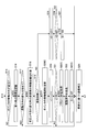
- FIG. 3 is a flowchart illustrating processing executed by the processing device according to the first embodiment.
- 3 is a flowchart illustrating processing executed by the processing device according to the first embodiment.
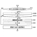
- 6 is a flowchart illustrating processing according to a modification of the first embodiment. 6 is a flowchart illustrating processing according to a modification of the first embodiment. It is a figure which shows the image of the screen of the state which increased the display magnification of the articles
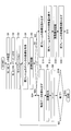
- FIG. 10 is a flowchart illustrating processing executed by the processing device according to the second embodiment.
- 10 is a flowchart illustrating processing executed by the processing device according to the second embodiment.
- FIG. 6 is a diagram illustrating an internal configuration of a processing apparatus according to a third embodiment.
- 10 is a flowchart illustrating processing executed by the processing device according to the third embodiment.
- 10 is a flowchart illustrating processing executed by the processing device according to the third embodiment.
- 14 is a flowchart illustrating processing executed by the processing device according to the fourth embodiment.
- FIG. 14 is a flowchart illustrating processing executed by the processing device according to the fourth embodiment.
- 10 is a flowchart illustrating processing executed by the processing device according to the fifth embodiment.
- 10 is a flowchart illustrating processing executed by the processing device according to the fifth embodiment. It is a figure which shows the image of the screen of the state which increased the display magnification of the articles
- FIG. 10 is a diagram illustrating an internal configuration of a processing apparatus according to a sixth embodiment.
- 18 is a flowchart illustrating processing executed by the processing device according to the sixth embodiment.
- 18 is a flowchart illustrating processing executed by the processing device according to the sixth embodiment. It is a figure explaining the determination using a threshold value. It is a figure explaining the determination using a threshold value.
- FIG. 10 is a diagram illustrating an internal configuration of a processing apparatus according to a seventh embodiment.
- 18 is a flowchart illustrating processing executed by the processing device according to the seventh embodiment.
- 18 is a flowchart illustrating processing executed by the processing device according to the seventh embodiment. It is a figure explaining the determination using a threshold value. It is a figure explaining the determination using a threshold value. It is a figure explaining the determination using a threshold value. It is a figure explaining the determination using a threshold value. It is a figure explaining the determination using a threshold value.
- FIG. 1 is a diagram showing a simulation system 100 according to the first embodiment.
- FIG. 2 is a diagram showing an internal configuration of the processing apparatus 120 shown in FIG.
- the simulation system 100 includes a screen 110A, a projection device 110B, 3D (3-dimensional) glasses 110C, a processing device 120, an operation terminal 130, and a position measurement device 140.
- Embodiment 1 The simulation system 100 can be applied to an assembly support system in order to grasp assembly workability in a virtual space, for example.
- an operation of assembling an electronic component such as a CPU (Central Processing Unit) module, a memory module, a communication module, or a connector on a mother board or the like can be performed in a virtual space.
- a CPU Central Processing Unit
- simulation system 100 can be applied not only to the assembly support system but also to various systems for confirming workability in a three-dimensional space.
- a projector screen can be used as the screen 110A.
- the size of the screen 110A may be set as appropriate according to the application.
- An image projected by the projection device 110B is displayed on the screen 110A.
- images of the articles 111 and 112 are displayed on the screen 110A.
- the projection device 110B may be any device that can project an image on the screen 110A.
- a projector can be used.
- the projection device 110B is connected to the processing device 120 via a cable 110B1, and projects an image input from the processing device 120 onto the screen 110A.
- the projection device 110B is of a type that can project a 3D image (stereoscopic image) onto the screen 110A.
- the screen 110A and the projection device 110B are examples of a display unit.
- the user who uses the simulation system 100 wears the 3D glasses 110C.
- the 3D glasses 110C may be any glasses that can convert an image projected on the screen 110A by the projection device 110B into a 3D image.
- polarized glasses for polarizing incident light or liquid crystal shutter glasses having a liquid crystal shutter are used. Can do.
- a liquid crystal display panel may be used instead of the screen 110A and the projection device 110B.
- the 3D glasses 110C may not be used.
- a head mounted display may be used instead of the screen 110A and the projection device 110B.
- the processing device 120 includes a position detection unit 121, a determination unit 122, a determination unit 123, a correction processing unit 124, a video output unit 126, a data holding unit 127, a drive control unit 128, and a communication unit 129.
- the processing device 120 is realized by a computer having a memory, for example.
- the position detection unit 121 performs image processing such as pattern matching on the image data input from the position measurement device 140 and detects the position and orientation of the operation terminal 130.
- the position of the operation terminal 130 is represented by a coordinate value in three-dimensional coordinates, and the posture is represented by an angle with respect to the three-axis direction of the three-dimensional coordinates.
- the position detection unit 121 converts the coordinate value in the three-dimensional coordinates of the operation terminal 130 into the coordinates in the image projected on the screen 110A, and outputs the coordinates as the coordinates representing the position of the pointer 130A.
- the coordinates representing the position of the pointer 130A are represented by values in the coordinate system of the image projected on the screen 110A.
- an XYZ coordinate system is used as the coordinate system of the image projected on the screen 110A.
- This XYZ coordinate system is a coordinate system in a virtual space in which an image is projected onto the screen 110A, and has a predetermined origin.
- the position of an image such as an article projected on the screen 110A is represented by coordinate values in the XYZ coordinate system.
- Such a position detection unit 121 is an example of a second detection unit.
- the position (coordinates) of the pointer 130A is an example of first coordinates.
- the position measurement device 140 may detect the position and orientation of the operation terminal 130.
- the determination unit 122 Based on the temporal change in the position of the pointer 130A detected by the position detection unit 121, the determination unit 122 has a movement distance of the position of the pointer 130A that is less than the predetermined distance L and the movement direction of the position of the pointer 130A is predetermined. Determine if it has changed over time.
- the determination unit 122 is an example of a first determination unit.
- the predetermined number is N1 times, and N1 times is, for example, five times.
- That the movement distance of the position of the pointer 130A is less than the predetermined distance L means that the movement distance from the time when the movement direction of the pointer 130A changes once to the time when the movement direction of the pointer 130A changes next is less than the predetermined distance L. That is.
- the movement distance of the position of the pointer 130A is less than the predetermined distance L, and the movement direction of the position of the pointer 130A changes for a predetermined number of times means that the movement direction does not change as described above and the predetermined distance L It is a predetermined number of times that the moving direction changes after the pointer 130A moves by less than the predetermined value.
- the movement direction of the position of the pointer 130A includes the position (coordinates) of the pointer 130A detected by the position detection unit 121 in the previous control cycle and the position (coordinates) of the pointer 130A detected by the position detection unit 121 in the current control cycle. ) And the amount of movement of coordinates obtained based on the above.
- the determination unit 122 determines whether or not at least one of the X component, the Y component, and the Z component of the movement amount is inverted, thereby changing the movement direction of the pointer 130A. Determine whether or not.
- the coordinates of the pointer 130A in the previous frame (hereinafter referred to as the previous frame) of the current frame (hereinafter referred to as the current frame) are (X i ⁇ 1 , Y i ⁇ 1 , Z i ⁇ 1 ), and the pointer in the current frame is determined.
- 130A's coordinates be (X i , Y i , Z i ).
- i is the frame number of the moving image projected on the screen 110A.
- the unit of the coordinates (X i ⁇ 1 , Y i ⁇ 1 , Z i ⁇ 1 ) of the pointer 130A is meter (m).
- the amount of movement (DX i , DY i , DZ i ) in the current frame can be expressed by equation (1).
- the determination unit 122 determines that the moving direction of the position of the pointer 130A has changed.
- the operation in which the position of the pointer 130A reciprocates in this way is not an operation intentionally performed by the user, but when the operation terminal 130 is moved so as to move the pointer 130A to the target point. This is a reciprocating motion that occurs when the hand holding the machine 130 fluctuates.
- the position of the pointer 130A does not always reciprocate, and the movement direction of the pointer 130A changes greatly. It is also possible. For example, at least one of the X, Y, and Z components in the moving direction is reversed when the moving direction changes greatly.
- the determination unit 122 determines that the moving distance of the position of the pointer 130A is less than the predetermined distance L. Then, it is determined whether the moving direction of the position of the pointer 130A has changed over a predetermined number of times.
- the moving distance is a moving distance from the time when the moving direction of the pointer 130A changes once to the time when the moving direction of the pointer 130A changes next.
- the predetermined distance L may be set longer than the distance that may be caused by hand wobbling or the like, or may be set to a value obtained through experiments or the like, in order to exclude the user's intentional actions. . For this reason, as an example, the predetermined distance L is set to 10 cm.
- the determination unit 123 monitors a trajectory obtained by temporal changes in the coordinates of the pointer 130A detected by the position detection unit 121, and determines whether the trajectory satisfies a predetermined condition.
- the determination unit 123 is an example of a second determination unit.
- the determination unit 123 based on the temporal change in the position of the pointer 130A detected by the position detection unit 121, the determination unit 123 has a moving distance of the position of the pointer 130A that is equal to or greater than a predetermined distance L, and the moving direction is It is determined whether it has changed over a predetermined number of times.
- the predetermined number of times is N2.
- the N2 times counted by the determination unit 123 is different from the N1 times counted by the determination unit 122. Further, the determination unit 123 determines whether or not the moving direction has been changed by the same determination method as the determination unit 122.
- the process determined by the determination unit 123 is a process for determining whether or not the pointer 130A has moved a predetermined distance L or more and the movement direction has changed N2 times or more.
- the determination unit 123 determines whether or not the movement direction of the pointer 130A does not change and the movement direction changes after the pointer 130A moves by a predetermined distance L or more has occurred a predetermined number of times.
- the determination process in which the determination unit 123 determines whether the movement direction of the pointer 130A has changed is the same as the process of determining whether the movement direction of the pointer 130A has changed in the determination process of the determination unit 122.
- the fact that the movement direction does not change does not correspond to the above-described change in the movement direction, as in the determination process of the determination unit 122.
- the determination unit 123 performs the above-described determination process in order to determine whether to return the sensitivity after the sensitivity indicating the movement amount of the pointer 130A with respect to the movement amount of the operation terminal 130 is reduced.
- an operation of moving the pointer 130A by a predetermined distance L or more and inverting the moving direction of the pointer 130A by operating the operation terminal 130 N2 times is set so that the sensitivity can be restored by repeating the above.
- the predetermined distance L may be set longer than the distance that the pointer 130A can move by touching the hand when the user moves the pointer 130A to the target point.
- Such a predetermined distance L may be set to a value obtained through experiments or the like, for example, 10 centimeters.
- N2 times is, for example, three times.
- the correction processing unit 124 operates the operation terminal 130.
- the sensitivity representing the amount of movement of the pointer 130A with respect to the amount of movement is reduced.
- Reducing the sensitivity representing the amount of movement of the pointer 130A relative to the amount of movement of the operation terminal 130 is, in other words, reducing the amount of movement of the pointer 130A relative to the amount of movement of the operation terminal 130.
- the correction processing unit 124 performs the following correction process to reduce the sensitivity representing the movement amount of the pointer 130A with respect to the movement amount of the operation terminal 130.
- the sensitivity representing the amount of movement of the pointer 130A is S (%).
- the sensitivity S (%) is a reference value in a state where the correction processing by the correction processing unit 124 is not performed, and is 100%.
- the reference value is a value set according to the user's preference or the like.
- the correction processing unit 124 corrects the coordinates (X i , Y i , Z i ) of the pointer 130A in the current frame to the coordinates (Xa i , Ya i , Za i ).
- the coordinates of the pointer 130A are corrected by setting the sensitivity S (%) to a value less than 100 (%) using the following equation (3).
- the coordinates of the pointer 130A in the previous frame are (X i ⁇ 1 , Y i ⁇ 1 , Z i ⁇ 1 ), and the movement amounts in the current frame are (DX i , DY i , DZ i ).
- the sensitivity S is used as a value, not as%.
- the correction processing unit 124 has the sensitivity representing the movement amount of the pointer 130A with respect to the movement amount of the operation terminal 130 reduced, and the determination unit 123 causes the movement distance of the position of the pointer 130A to be a predetermined distance L or more. If it is determined that the movement direction has changed over a predetermined number of times, the sensitivity representing the movement amount of the pointer 130A relative to the movement amount of the operation terminal 130 is restored.
- the correction processing unit 124 restores the sensitivity representing the amount of movement of the pointer 130A relative to the amount of movement of the operation terminal 130 by returning the sensitivity S (%) in Expression (3) to 100 (%). .
- the output terminal of the video output unit 126 is connected to the projection device 110B by a cable 110B1.
- the video output unit 126 outputs an image specified by the article data of the articles 111 and 112 held in the data holding unit 127 to the projection device 110B and displays it on the screen 110A.
- the video output unit 126 displays a pointer 130A on the projection device 110B.
- the position of the pointer 130A in the image displayed on the screen 110A is displayed at the coordinates of the pointer 130A corrected by the correction processing unit 124.
- the coordinates of the pointer 130A corrected by the correction processing unit 124 are obtained by correcting the coordinates before correction of the pointer 130A determined by the position and orientation of the operation terminal 130 detected by the position detection unit 121.
- the video output unit 126 is an example of a display control unit.
- the data holding unit 127 holds data such as article data representing the coordinates and shape of the articles 111 and 112, vibration data representing a vibration pattern corresponding to the tactile sensation of the articles 111 and 112, and image data of the pointer 130A.
- the data holding unit 127 is realized by a memory and is an example of a data storage unit.
- the drive control unit 128 When the determination unit 122 determines that the movement distance of the pointer 130A is less than the predetermined distance L and the movement direction of the pointer 130A has changed a predetermined number of times, the drive control unit 128 has a predetermined vibration pattern.
- the drive signal is output. This drive signal is a signal for driving the vibration element of the operation terminal 130.
- the communication unit 129 is a communication unit that performs wireless communication with the operation terminal 130, and can perform wireless communication according to a standard such as Bluetooth (registered trademark) or WiFi (Wireless Fidelity).
- the communication unit 129 transmits a drive signal generated by the drive control unit 128 to the operation terminal 130.
- the communication unit 129 may be a communication unit that performs wired communication with the operation terminal 130.
- the operation terminal 130 is a terminal that is held by a user using the simulation system 100 and controls the position of the pointer 130A displayed on the screen 110A.
- the operation terminal 130 has a marker 132 and a vibration element 133.
- the marker 132 has a plurality of spheres and reflects infrared rays emitted from the position measuring device 140 in various directions.
- the marker 132 is used for position detection of the operation terminal 130 by the position measurement device 140.
- the vibration element 133 is provided to cause the operation terminal 130 to generate vibration.
- the vibration element 133 is driven by a drive signal generated by the drive control unit 128.
- the vibration element 133 is an example of a movable element.
- the position measurement device 140 includes infrared cameras 140A, 140B, and 140C, and is connected to the position detection unit 121 by cables 141A, 141B, and 141C, respectively.
- the infrared cameras 140 ⁇ / b> A, 140 ⁇ / b> B, and 140 ⁇ / b> C irradiate the operation terminal 130 with infrared rays and photograph the reflected light reflected by the marker 132.
- the position measurement device 140 transfers the image data output from the infrared cameras 140A, 140B, and 140C to the position detection unit 121.
- the position measurement device 140 is an example of a first detection unit.
- FIG. 3 is a perspective view of a computer system to which the processing device 120 of the first embodiment is applied.
- a computer system 10 shown in FIG. 3 includes a main body 11, a display 12, a keyboard 13, a mouse 14, and a modem 15.
- the main unit 11 includes a CPU (Central Processing Unit), an HDD (Hard Disk Drive), a disk drive, and the like.
- the display 12 displays an analysis result or the like on the screen 12A according to an instruction from the main body 11.
- the display 12 may be a liquid crystal monitor, for example.
- the keyboard 13 is an input unit for inputting various information to the computer system 10.
- the mouse 14 is an input unit that designates an arbitrary position on the screen 12 ⁇ / b> A of the display 12.
- the modem 15 accesses an external database or the like and downloads a program or the like stored in another computer system.
- a program for causing the computer system 10 to function as the processing device 120 is stored in a portable recording medium such as the disk 17 or downloaded from the recording medium 16 of another computer system using a communication device such as the modem 15. Are input to the computer system 10 and compiled.
- a program that causes the computer system 10 to have a function as the processing device 120 causes the computer system 10 to operate as the processing device 120.
- This program may be stored in a computer-readable recording medium such as the disk 17.
- the computer-readable recording medium is limited to a portable recording medium such as a disk 17, an IC card memory, a magnetic disk such as a floppy (registered trademark) disk, a magneto-optical disk, a CD-ROM, or a USB (Universal Serial Bus) memory. It is not something.
- the computer-readable recording medium includes various recording media accessible by a computer system connected via a communication device such as a modem 15 or a LAN.
- FIG. 4 is a block diagram illustrating a configuration of a main part in the main body 11 of the computer system 10.
- the main body 11 includes a CPU 21 connected by a bus 20, a memory unit 22 including a RAM or a ROM, a disk drive 23 for the disk 17, and a hard disk drive (HDD) 24.
- the display 12, the keyboard 13, and the mouse 14 are connected to the CPU 21 via the bus 20, but these may be directly connected to the CPU 21.
- the display 12 may be connected to the CPU 21 via a known graphic interface (not shown) that processes input / output image data.
- the keyboard 13 and the mouse 14 are input units of the processing device 120.
- the display 12 is a display unit that displays input contents and the like for the processing device 120 on the screen 12A.
- the computer system 10 is not limited to the configuration shown in FIGS. 3 and 4, and various known elements may be added or alternatively used.
- FIG. 5 is a perspective view showing the operation terminal 130.
- the operation terminal 130 includes a housing 131, a marker 132, a vibration element 133, buttons 134A and 134B, and a guide bar 135.
- the operation terminal 130 has a guide bar 135 serving as an index of the position of the pointer 130A held by the user with the hand facing the screen 110A, and moves the position of the operation terminal 130 back and forth, left and right, and up and down, thereby causing the screen 110A.
- a terminal that can move the pointer 130A displayed on the back and forth, left and right, and up and down.
- the operation terminal 130 is held with the guide bar 135 facing the screen 110A, and the left and right positional relationship is represented with reference to the user facing the screen 110A.
- the front and rear positional relationship is represented with reference to the user facing the screen 110A while holding the operation terminal 130 with the guide bar 135 facing the screen 110A.
- the surface of the casing 131 on which the vibration element 133 is provided is referred to as the upper surface, and the side on which the guide bar 135 is attached is referred to as the front side.
- the housing 131 is made of, for example, resin and has a size that is just right for the user to hold.
- a vibration element 133 is disposed on the upper surface of the housing 131.
- the marker 132 has a plurality of spheres 132A and wires 132B.
- the plurality of spheres 132A are attached to the housing 131 by wires 132B.
- the marker 132 Since the marker 132 is used for detecting the position and orientation of the operation terminal 130 by the position measuring device 140, the marker 132 reflects infrared rays emitted from the position measuring device 140 in various directions. The infrared rays reflected by the marker 132 are captured by the infrared cameras 140A and 140B, and the position detection unit 121 performs image processing to detect the position and orientation of the marker 132. The position and orientation of the marker 132 represent the position and orientation of the operation terminal 130.
- the marker 132 may have any number of spheres as long as it can reflect infrared rays in various directions without regularity, and the position of the sphere is not particularly limited. Moreover, it may not be a sphere, and the detection of the marker 132 is not limited to the method using infrared rays. Any marker 132 may be used as long as the position of the operation terminal 130 can be detected.
- the vibration element 133 is provided on the upper surface of the housing 131.
- the vibration element 133 is driven by a drive signal generated by the drive control unit 128.
- the vibration element 133 may be an element that generates vibration, such as a piezoelectric element or an LRA (LinearLineResonant Actuator). When the vibration element 133 is driven, vibration is generated.
- LRA LinearLineResonant Actuator
- buttons 134A and 134B are push button switches that are operated when various functions of the operation terminal 130 are executed.
- Examples of the function include various functions such as a function for switching on / off wireless communication with the processing device 120 and a function for adjusting the display brightness of the pointer 130A.
- the guide bar 135 is attached to the front side of the casing 131.
- the guide bar 135 is a member that serves as an index of the position of the pointer 130A, and is provided to make it easy to recognize the position where the pointer 130A is displayed on the screen 110A.
- the guide bar 135 is an elongated triangular plate-like member.
- the guide bar 135 may have any shape as long as it becomes an index or a reference point when a user holding the operation terminal 130 moves the position of the pointer 130A displayed on the screen 110A. May be.
- the operation terminal 130 may not include the guide bar 135.
- FIG. 6 is a diagram showing the vibration motor 133A.
- the vibration motor 133A has a base 133A1 and a rotating part 133A2.
- a winding coil is provided inside the base 133A1.
- the rotating part 133A2 has an eccentric structure, and when it rotates, vibration is transmitted to the base 133A1.
- Such a vibration motor 133A may be used instead of the vibration element 133 shown in FIG.
- FIG. 7 is a diagram illustrating a configuration of the electric system of the operation terminal 130.
- the housing 131 and the guide bar 135 are shown in a simplified manner, and the marker 132 and the vibration element 133 are omitted.
- the operation terminal 130 includes a vibration element 133, buttons 134A and 134B, a communication unit 136, a button determination unit 137, and a signal generation unit 138.
- the button determination unit 137 and the signal generation unit 138 are realized by an arithmetic processing device such as a microcomputer, for example.
- a button determination unit 137 and a signal generation unit 138 are connected to the communication unit 136.
- the communication unit 136 is a communication unit that performs wireless communication with the communication unit 129 of the processing device 120.
- the communication unit 136 performs wireless communication according to standards such as Bluetooth, WiFi, Xbee, and zigbee.
- the communication unit 136 transmits a signal input from the button determination unit 137 to the processing device 120.
- the communication unit 136 receives a drive signal generated by the drive control unit 128 of the processing device 120 and outputs it to the signal generation unit 138.
- the button determination unit 137 is a determination unit that determines whether or not the button 134A is operated and whether or not the button 134B is operated. For example, the wireless communication with the processing device 120 is turned on / off, and the display brightness of the pointer 130A is determined. The operation content such as adjustment is determined. The button determination unit 137 outputs a signal representing the operation content to the communication unit 136.
- the signal generation unit 138 amplifies the drive signal received by the communication unit 136 and drives the vibration element 133. Note that the signal generation unit 138 may be regarded as a drive control unit.
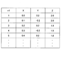
- FIG. 8 is a diagram illustrating the coordinates of the pointer 130A acquired by the determination units 122 and 123 in each frame.
- the number of frames i and the coordinates (X i , Y i , Z i ) of the pointer 130A are recorded in association with each other.
- Such coordinates of the pointer 130 ⁇ / b> A are held by the data holding unit 127.
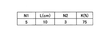
- FIG. 9 is a diagram illustrating data used by the determination units 122 and 123 and the correction processing unit 124.
- the data shown in FIG. 9 is held by the data holding unit 127.
- the data shown in FIG. 9 includes a predetermined number N1 used by the determination unit 122 for determination, a distance L, a predetermined number N2 used by the determination unit 123 for determination, and a value K used when the correction processing unit 124 decreases the sensitivity S. Is the data associated with. Data used by the determination units 122 and 123 and the correction processing unit 124 for determination processing or the like is held by the data holding unit 127.
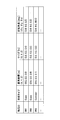
- FIG. 10 is a diagram showing article data.
- the article data is data representing the coordinates and shape of the article displayed on the screen 110A.
- the article data has an article ID, a shape type, reference coordinates, a size, and a rotation angle.
- the shape type represents the outer shape of the article.
- the shape types indicate Cuboid (cuboid) and Cylinder (cylindrical body).
- the reference coordinate indicates the coordinate value of a point that serves as a reference for coordinates representing the entire article.
- the unit of the coordinate value is meter (m).
- An XYZ coordinate system is used as the coordinate system.
- This XYZ coordinate system is a coordinate system in a virtual space representing the position of an image displayed on the screen 110A.
- the size represents the length of the article in the X-axis direction, the length in the Y-axis direction, and the length in the Z-axis direction.
- the unit is meters (m).
- the length in the X-axis direction represents the vertical length
- the length in the Y-axis direction represents the height
- the length in the Z-axis direction represents the depth (the length in the horizontal direction).
- the rotation angle is represented by rotation angles ⁇ x, ⁇ y, and ⁇ z with respect to the X-axis direction, the Y-axis direction, and the Z-axis direction.
- the unit is degree (deg.).
- the rotation angle ⁇ x is an angle for rotating the article about the X axis as a rotation axis.
- the rotation angles ⁇ y and ⁇ z are angles at which the article is rotated about the Y axis and the Z axis as rotation axes, respectively.
- the positive directions of the rotation angles ⁇ x, ⁇ y, and ⁇ z may be determined in advance.
- an image specified by the article data can be represented in the same manner as the article image displayed by the CAD data.
- the article data is stored in the data holding unit 127 of the processing device 120.
- FIG. 11 is a diagram illustrating an example of an image of an article.
- FIG. 11 shows three articles represented by the article data of FIG.
- An article with an article ID of 001 has a shape type of Cuboid (cuboid), reference coordinates (X, Y, Z) of (0.0, 0.0, 0.0), and a size of (0.8, 0.2, 0.4), and the rotation angles ⁇ x, ⁇ y, ⁇ z are (0.0, 0.0, 0.0).
- An article with an article ID of 002 has a shape type of Cuboid (cuboid), reference coordinates (X, Y, Z) of (0.6, 0.2, 0.0), and a size of (0.2, 0.2, 0.1), and the rotation angles ⁇ x, ⁇ y, ⁇ z are (0.0, 0.0, 0.0).
- the article with the article ID 002 is arranged on the article with the article ID 001.
- the article with the article ID 003 has a shape type of Cylinder, a reference coordinate (X, Y, Z) of (0.8, 0.3, 0.1), and a size of (0.2 , 1.0, 0.3), and the rotation angles ⁇ x, ⁇ y, ⁇ z are (0.0, 0.0, 90.0).
- the article with the article ID 003 is connected to the X axis positive direction side of the article with the article ID 002 in a state where the article ID is rotated 90 degrees about the Z axis.
- the article in the image projected on the screen 110A using the article data having the article ID, shape type, reference coordinates, size, and rotation angle shown in FIG. Specify the coordinates and shape of
- the coordinates of the eight vertices are the length in the X-axis direction, the length in the Y-axis direction, the length in the Y-axis direction, and the Z-axis direction with respect to the reference coordinates. Can be obtained by adding or subtracting the length.
- the coordinates of the eight vertices represent the coordinates of the corner of the article whose shape type is Cuboid.
- the expression representing the 12 sides is an expression representing the coordinates of the Edge of the article whose shape type is Cuboid.
- the expressions representing the eight vertices and / or the expressions representing the 12 sides are obtained, the expressions representing the six surfaces of the article whose shape type is Cuboid are obtained, and the coordinates of the surface are obtained. be able to.
- the shape type is Cylinder (cylindrical body)
- An expression representing a certain circle (or ellipse) can be obtained.
- an equation representing a circle (or ellipse) at both ends and a reference coordinate are used, an equation representing the coordinates of the circle (or ellipse) at both ends can be obtained.
- the coordinates of the side surface of the cylinder can be obtained by using an expression representing the coordinates of the circles (or ellipses) at both ends.
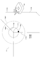
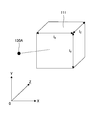
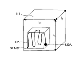
- 12 and 13 are diagrams illustrating how the simulation system 100 decreases the sensitivity S when the user moves the pointer 130A. 12 and 13 show an article 111 and a pointer 130A displayed on the screen 110A.
- the article 111 is a cubic article having a side length of 50 cm.
- the display magnification M of the article 111 is 100%
- the sensitivity S representing the movement amount of the pointer 130A with respect to the movement amount of the operation terminal 130 is 100%.
- the pointer 130A when the user is trying to move the pointer 130A to the corner 111B, at a certain moment, the pointer 130A is in the vicinity of the side 111E4 between the corners 111B and 111C due to hand wobbling.
- the simulation system 100 sets an allowable range 130A1 of the coordinates of the corner 111B.
- the allowable range 130A1 is a spherical region centered on the corner 111B and defined by a predetermined radius.
- the pointer 130A is handled as being at the corner 111B.
- the radius of the allowable range 130A1 is 5 cm. As an example, this is 10% of the length (50 cm) of one side of the article 111. That is, the allowable range 130A1 has a diameter of 10 cm.
- the simulation system 100 does not handle the pointer 130A as being at the corner 111B.
- the range 130A2 is a spherical area having a radius between the position of the pointer 130A and the corner 111B when the user's hand touches the corner 111B and the pointer 130A is farthest from the corner 111B. It is.
- the position of the pointer 130A shown in FIG. 12 is a position when the pointer 130A is farthest from the corner 111B due to the shaking of the user's hand. For this reason, the pointer 130A is located on the boundary of the range 130A2.
- the radius of the range 130A2 is 15 cm. That is, the diameter of the range 130A2 is 30 cm.
- the simulation system 100 reduces the sensitivity S to 25%.
- the sensitivity of the movement amount of the pointer 130A is reduced to 1 ⁇ 4.
- the hand shake range when the sensitivity S is reduced is 130A2M
- the diameter of the range 130A2M is 7.5 cm
- the pointer 130A is within the allowable range 130A1 as shown in FIG. It will be.
- the pointer 130A falls within the allowable range 130A1, the pointer 130A is handled as being at the corner 111B by the simulation system 100.
- the user can easily move the pointer 130A to the corner 111B.
- the simulation system 100 drives the vibration element 133 using predetermined vibration data when the sensitivity S is reduced as described above. As a result, the user is informed by the tactile sensation that the sensitivity S has been reduced.
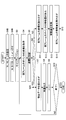
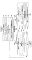
- FIG. 14 and 15 are flowcharts showing processing executed by the processing device 120 according to the first embodiment.
- the processing device 120 As an example, a case where an image of the article 111 is displayed on the screen 110A (see FIG. 1) will be described.
- the processing device 120 starts processing after the power is turned on (START).
- the processing device 120 reads from the data holding unit 127 and sets the predetermined number N1 and distance L used by the determination unit 122 for determination, the predetermined number N2 used by the determination unit 123 for determination, and the value K used by the correction processing unit 124. (Step S1).
- the determination unit 122 sets the predetermined number N1 and the distance L, the determination unit 123 sets the predetermined number N2, and the correction processing unit 124 sets the value K.
- the value K is a value that represents the rate at which the sensitivity S is reduced, and is 75 (%) as an example here.
- the processing device 120 sets the sensitivity S to 100%, the display magnification M to 100%, the frame number i to 1, and the count numbers n1 and n2 to 0 (step S2).
- the count number n1 is the number of times the movement direction of the pointer 130A changes before the sensitivity S is lowered, and the count number n2 is when the user performs a predetermined operation for returning the sensitivity S to 100%. This is the number of times the moving direction of the pointer 130A changes.
- the sensitivity S is set by the determination unit 122, the display magnification M and the frame number i are set by the video output unit 126, the count number n1 is set by the determination unit 122, and the count number n2 is set by the determination unit 123. Do.
- the processing device 120 calibrates the position of the operation terminal 130 (step S3).
- Calibration is a process of associating the initial position of the operating terminal 130 detected by the position detection unit 121 with the position of the pointer 130A in the image (virtual space) displayed on the screen 110A.
- the position detection unit 121 has a function of performing calibration. For this reason, the process of step S3 is performed by the position detection unit 121.
- the processing device 120 acquires the coordinates of the pointer 130A in the current frame (step S4).
- the coordinates of the pointer 130A are obtained when the position detection unit 121 converts the coordinate value in the three-dimensional coordinates of the operation terminal 130 into the coordinates in the image projected on the screen 110A.
- the processing device 120 records the coordinates of the pointer 130A acquired in step S4 in the data holding unit 127 (step S5).
- the process of step S5 is performed by the position detection unit 121.
- the processing device 120 determines whether or not the number of frames i is 1 (step S6).
- the process of step S6 is performed by the video output unit 126.
- step S7 If the processing device 120 determines that the number of frames i is 1 (S6: YES), it reads the article data from the data holding unit 127 (step S7).
- the process of step S6 is performed by the video output unit 126.
- the user selects the article 111 and the video output unit 126 reads the article data of the article 111 from the data holding unit 127.
- the processing device 120 displays the article 111 selected by the user on the screen 110A (step S8).
- the processing device 120 reads the data of the article 111 from the article data (see FIG. 10) and displays it on the screen 110A.
- the display of the article 111 is performed by the video output unit 126.
- the processing device 120 increments the frame number i (step S9).
- the process of step S9 is performed by the video output unit 126.
- the processing device 120 determines whether or not the processing is finished (step S10).
- the end of the process can be selected by operating the button 134A or 134B on the operation terminal 130.
- processing device 120 determines that the processing is not finished (S10: NO), it returns the flow to step S4. If the processing device 120 determines that the end of processing has been selected (S10: YES), the processing device 120 ends the series of processing (END).
- step S6 If the processing device 120 determines in step S6 that the number of frames i is not 1 (S6: NO), it reads the coordinates of the pointer 130A of the previous frame from the data holding unit 127 (step S11). The process of step S11 is performed by the determination unit 122.
- the processing device 120 calculates the movement amount of the pointer 130A in the current frame based on the coordinates of the pointer 130A in the current frame and the coordinates of the pointer 130A in the previous frame (step S12).
- the processing device 120 calculates the amount of movement of the pointer 130A in the current frame using equation (1).
- the process of step S12 is performed by the determination unit 122.
- the processing device 120 records the movement amount calculated in step S12 in the data holding unit 127 (step S13).
- the process of step S13 is performed by the determination unit 122.
- the processing device 120 reads the movement amount of the pointer 130A of the previous frame from the data holding unit 127 (step S14).
- the process of step S14 is performed by the determination unit 122.
- the processing device 120 determines whether the movement direction of the pointer 130A has changed based on the movement amount of the pointer 130A of the current frame and the movement amount of the pointer 130A of the previous frame (step S15).
- the processing device 120 determines whether any one of the three inequalities represented by Expression (2) is satisfied.
- the process of step S15 is performed by the determination unit 122.
- step S16 the processing device 120 records the coordinates of the pointer 130A at the time of the change in the data holding unit 127 (step S16).
- the coordinates of the pointer 130A at the time of change are the coordinates of the pointer 130A in the current frame.
- the process of step S16 is performed by the determination unit 122.
- the processing device 120 determines whether or not the movement direction is changed for the first time (step S17).
- the processing device 120 may determine whether or not the movement direction is changed for the first time based on whether or not the coordinates of the pointer 130A at the time of the change are recorded in the data holding unit 127.
- the process of step S17 is performed by the determination unit 122.
- Step S18 The process of step S18 is performed by the determination unit 122.
- the processing apparatus 120 determines whether or not the movement distance obtained in step S18 is less than the predetermined distance L (step S19). The process of step S19 is performed by the determination unit 122.
- step S1 If the processing device 120 determines that the moving distance is less than the predetermined distance L (S19: YES), the processing device 120 increments a count number n1, which is the number of times the moving direction changes when the moving distance of the pointer 130A is less than L (step S1). S20). The process of step S20 is performed by the determination unit 122.
- the processing apparatus 120 determines whether the count number n1 is equal to the predetermined number N1 (step S21). The process of step S21 is performed by the determination unit 122.
- the processing device 120 determines that the count number n1 is not equal to the predetermined number N1 (S21: NO), the processing device 120 causes the flow to proceed to step S24.
- the processing device 120 determines that the count number n1 is equal to the predetermined number N1 (S21: YES).
- the processing device 120 transmits a drive signal to the operation terminal 130 (step S22).
- the drive signal is transmitted from the drive control unit 128 to the operation terminal 130 via the communication unit 129.
- step S21 is performed when the determination unit 122 causes the drive control unit 128 to transmit a drive signal.
- the processing device 120 decreases the sensitivity S by K (step S23). That is, the sensitivity after the decrease is SK (%). For example, when K is 75 (%), the sensitivity S after the decrease is 25%.
- the process of step S23 is performed when the determination unit 122 causes the correction processing unit 124 to reduce the sensitivity S.
- the processing device 120 corrects the coordinates of the pointer 130A based on the sensitivity S (step S24).
- the processing in step S23 is performed by the correction processing unit 124 correcting the coordinates of the pointer 130A using equation (3).
- the correction processing unit 124 correcting the coordinates of the pointer 130A using equation (3). In the state where the sensitivity S is not reduced and is 100 (%), correction is performed in the state where S is 100 (%) in the equation (3). In other words, in this case, the coordinates of the pointer 130A do not change.
- the processing device 120 returns the flow to step S7 when the process of step S24 ends.
- step S15 determines in step S15 that the moving direction has not changed (S15: NO)
- the process proceeds to step S24. This is because when the moving direction has not changed, it is not necessary to perform the processing of steps S16 to S23.
- step S17 If the processing device 120 determines in step S17 that the movement direction has not changed for the first time (S17: YES), the processing device 120 advances the flow to step S24.
- the first change in the moving direction is because the coordinates at the previous change do not exist and the moving distance cannot be calculated.
- step S23 When the loop from step S4 to step S6 and further from step S11 to step S15 is repeated N1 times (three times), and the count number n1 representing the number of times the moving direction has changed becomes equal to N1, in step S23 The sensitivity S is lowered by K.
- step S25 If the processing device 120 determines that the movement distance is not less than the predetermined distance L (S19: NO), the processing device 120 increments a count number n2, which is the number of times the movement direction changes when the movement distance of the pointer 130A is L or more (step). S25). The process of step S25 is performed by the determination unit 123.
- the processing apparatus 120 determines whether the count number n2 is equal to the predetermined number N2 (step S26). The process of step S26 is performed by the determination unit 123.
- step S24 the processing device 120 determines that the count number n2 is not equal to the predetermined number N2 (S26: NO). If the processing device 120 determines that the count number n2 is not equal to the predetermined number N2 (S26: NO), the flow proceeds to step S24. This is because the sensitivity S is not returned until the count number n2 reaches the predetermined number N2.
- the processing device 120 determines that the count number n2 is equal to the predetermined number N2 (S26: YES), the processing device 120 returns the sensitivity S to 100 (%) (step S27). Specifically, when the determination unit 123 transmits a trigger signal for returning the sensitivity S to 100 (%) to the correction processing unit 124, the sensitivity S is returned to 100 (%) by the correction processing unit 124.
- step S27 When the processing device 120 finishes the process of step S27, the flow proceeds to step S24.
- the processing device 120 repeatedly executes the above processing until it is determined in step S10 that the processing has ended.
- the sensitivity S of the pointer 130A is reduced to 1 ⁇ 4.
- the hand shake range 130A2 shown in FIG. 12 is reduced to the hand shake range 130A2M shown in FIG.
- the diameter of hand shake range 130A2M is 1 ⁇ 4 of the diameter of hand shake range 130A2.
- the user can easily move the pointer 130A to the target position.
- the operation terminal 130 is moved so as to change the moving direction by 10 centimeters or more and 5 times or more while the sensitivity S is lowered, the sensitivity S can be returned to 100 (%). Therefore, the sensitivity S can be easily restored.
- the pointer 130A can be easily moved to the target position. This is because the sensitivity S of the pointer 130A is relatively reduced.
- the correction processing unit 124 corrects the display magnification M.
- FIGS. 16 and 17 are flowcharts showing processing according to the modification of the first embodiment.
- the processing shown in FIGS. 16 and 17 has the contents in which steps S23 and S27 in the flowchart of the first embodiment are replaced with S23A and S27A, and step S24 is deleted.
- step S23A the processing device 120 increases the display magnification M by K2 (step S23A).
- K2 is assumed to be 300 (%).
- the display magnification M after the increase is 400 (%) when M + K2 (%).
- the process of step S23A is performed when the determination unit 122 causes the correction processing unit 124 to increase the display magnification M.
- step S27A when determining that the count number n2 is equal to the predetermined number N2 (S26: YES), the processing device 120 returns the display magnification M to 100 (%) (step S27A). Specifically, the determination unit 123 transmits a trigger signal for returning the display magnification M to 100 (%) to the correction processing unit 124, whereby the display magnification M is returned to 100 (%) by the correction processing unit 124.
- step S7 when NO in step S15, YES in step S17, NO in step S21, NO in step S26, and when step S23A and step S27A are completed. Will do.
- FIG. 18 is a diagram illustrating an image of the screen 110A in a state where the display magnification M of the article 111 is increased.
- the length of each side of the article 111 is four times as the display magnification M is increased to 400 (%). Along with this, the diameter of the allowable range 130A1 is quadrupled.
- the range 130A2 where the user can touch is relatively 1 ⁇ 4 compared to the article 111 and the allowable range 130A1.
- the touched range 130A2 is within the allowable range 130A1, and the user can easily move the pointer 130A to the target position. Become.
- FIG. 19 is a diagram illustrating an internal configuration of the processing apparatus 120B according to the second embodiment.
- the processing device 120B includes a position detection unit 121, a determination unit 122B, a determination unit 123, a correction processing unit 124, an integration unit 125, a video output unit 126, a data holding unit 127, a drive control unit 128, and a communication unit 129.
- the processing device 120B is realized by a computer having a memory, for example.
- the processing device 120B has a configuration in which the determination unit 122 of the processing device 120 of the first embodiment is replaced with a determination unit 122B, and an integration unit 125 is added.
- symbol is attached
- the determination unit 122B is different from the determination unit 122 of the first embodiment in the method of reducing the sensitivity S.
- K set by the correction processing unit 124 is 500 (%).
- 20 and 21 are flowcharts showing processing executed by the processing device 120B of the second embodiment.
- the processing device 120B of the second embodiment.
- FIG. 1 a case where an image of the article 111 is displayed on the screen 110A (see FIG. 1) will be described.
- FIGS. 20 and 21 replaces steps S1, S2, and S23 of the first embodiment with S1B, S2B, and S23B, respectively, and adds step S15B when determined NO in step S15. It is the content which added step S24B before. Hereinafter, the difference will be mainly described.
- the determination unit 122B uses the predetermined number of times N1, the distance L, the determination unit 123 uses the determination number N2, and the correction processing unit 124 uses the value K. Is read from the data holding unit 127 and set (step S1B).
- the determination unit 122B sets the predetermined number N1 and the distance L, the determination unit 123 sets the predetermined number N2, and the correction processing unit 124 sets the value K.
- the value K is a value that represents the rate at which the sensitivity S is reduced, and is 500 (%) as an example here.
- the processing device 120B sets the sensitivity S to 100%, the display magnification M to 100%, the integrated value I of the moving distance of the pointer 130A, the number of frames i to 1, and the count numbers n1 and n2 to 0 (step S2B).
- the integrated value I of the moving distance of the pointer 130A indicates a value obtained by integrating the distance moved by the pointer 130A.
- the sensitivity S is set by the determination unit 122B, the display magnification M and the number of frames i are set by the video output unit 126, the count number n1 is set by the determination unit 122B, and the count number n2 is set by the determination unit 123. Do.
- the integration value 125 is set by the integration unit 125.
- Processing device 120B performs the processing from step S3 to step S15, and if it is determined in step S15 that the moving direction has not changed (S15: NO), the flow proceeds to step S15B.
- the processing apparatus 120 determines whether the count number n1 is 0 (step S15B). If the count number n1 is not 0 (S15B: NO), the processing device 120 advances the flow to step S24B.
- the processing apparatus 120 decreases the sensitivity S by KI in step S23B (step S23B). That is, the sensitivity after the decrease is S-KI (%). For example, when K is 500 (%) and the integrated value I of the movement distance of the pointer 130A is 0.15 (m), KI is 75 (%) and the sensitivity S after the decrease is 25%.
- the process of step S23B is performed when the determination unit 122 causes the correction processing unit 124 to reduce the sensitivity S.
- step S23B only the numerical value when the integrated value I is expressed in meters is multiplied by K.
- step S23B the processing device 120 advances the flow to step S24B.
- the processing device 120 updates the integrated value I by adding the movement amount of the pointer 130A of the current frame to the integrated value I (step S24B).
- step S24B the moving distance of the pointer 130A is integrated.
- the processing in step S24B is performed by the integrating unit 125.
- the processing apparatus 120 advances the flow to step S24 when step S24B ends.
- the processing device 120B repeatedly executes the above processing until it is determined to end in step S10.
- the sensitivity S of the pointer 130A is reduced to 1 ⁇ 4.
- the hand shake range 130A2 shown in FIG. 12 is reduced to the hand shake range 130A2M shown in FIG.
- the diameter of hand shake range 130A2M is 1 ⁇ 4 of the diameter of hand shake range 130A2.
- the user can easily move the pointer 130A to the target position.
- the pointer 130A can be easily moved to the target position. This is because the sensitivity S of the pointer 130A is relatively reduced.
- the processing shown in FIG. 14 and FIG. 15 of the first embodiment is modified to the processing shown in FIG. 20 and FIG. 21 of the second embodiment, and the integrated value I is taken into consideration.
- the display magnification M may be increased by K2 ⁇ I.
- the value of K2 may be set to an appropriate value as K (75 (%)) in the first embodiment is changed to 500 (%). For example, if K2 is set to 2000 and I is 0.15 (m), K2 ⁇ I is 300 (%), so the display magnification M can be 400 (%).
- the operability may be improved by increasing the display magnification M of the article 111.
- FIG. 22 is a diagram illustrating an internal configuration of the processing apparatus 120C according to the third embodiment.
- the processing device 120C includes a position detection unit 121, a determination unit 122C, a determination unit 123, a correction processing unit 124, a recording unit 125C, a video output unit 126, a data holding unit 127, a drive control unit 128, and a communication unit 129.
- the processing device 120C is realized by, for example, a computer having a memory.
- the processing device 120C has a configuration in which the determination unit 122 of the processing device 120 of the first embodiment is replaced with a determination unit 122C and a recording unit 125C is added.
- symbol is attached
- the determination unit 122C is different from the determination unit 122 of the first embodiment in the method of reducing the sensitivity S.
- K set by the correction processing unit 124 is 2.77 ⁇ 10 6 (%).
- FIG. 23 and 24 are flowcharts showing processing executed by the processing apparatus 120C of the third embodiment.
- FIG. 25 is a diagram illustrating data representing the coordinates of the pointer 130A acquired by the processing device 120C.
- FIG. 1 a case where an image of the article 111 is displayed on the screen 110A (see FIG. 1) will be described.
- step S20C is inserted between steps S19 and S20 of the first embodiment, and step S22C is inserted between steps S21 and S22 of the first embodiment.
- Step S23 is replaced with S23C.
- the processing device 120C When the processing device 120C starts processing (START), the processing device 120C executes the processing of steps S1 to S19. These processes are the same as those in the first embodiment.
- the processing device 120 determines that the moving distance is less than the predetermined distance L (S19: YES)
- the processing device 120 updates the moving range of the pointer 130A (step S20C).
- the processing device 120 updates the moving range of the pointer 130A (step S20C).
- the processing device 120 by recording the coordinates of the pointer 130A, the three-dimensional space including the locus when the pointer 130A moves is recorded as the movement range.
- the recording unit 125C performs the process of step S20C.
- the coordinates of the pointer 130A are data in which the count number n1 is associated with the coordinate values (X, Y, Z) of the pointer 130A. From such coordinates of the pointer 130A, the movement range is obtained as follows.
- the movement range is expressed by the following equation (4).
- Xmax is updated to Xi.
- step S20 When the processing device 120 finishes the process of step S20C, it increments the count number n1 (step S20).
- the process of step S20 is performed by the determination unit 122.
- the processing device 120 determines that the count number n1 is equal to the predetermined number N1 (S21: YES).
- the processing device 120 acquires the parameter P (step S22C).
- the parameter P is obtained as follows.
- the recording unit 125C performs the process in step S22C.
- the parameter P is a volume V of a rectangular parallelepiped in a range with a margin of ⁇ (m) in each direction of the movement range.
- V is expressed by the following equation (6).
- step S22C the processing device 120 transmits a drive signal to the operation terminal 130 (step S22).
- the drive signal is transmitted from the drive control unit 128 to the operation terminal 130 via the communication unit 129.
- the volume V of the rectangular parallelepiped having a margin of ⁇ (m) in each direction of the movement range is used, but the movement range is represented without the margin ⁇ (m). It may be the volume of the region.
- step S23C the processing device 120 decreases the sensitivity S by K ⁇ P (step S23C). That is, the sensitivity after the decrease is S-KP (%). For example, when K is 2.77 ⁇ 10 6 (%) and P is 2.7 ⁇ 10 ⁇ 5 (m 3 ), the sensitivity S after the decrease is 25%.
- the processing in step S23C is performed by the determination unit 122 causing the correction processing unit 124 to reduce the sensitivity S by K ⁇ P based on the parameter P obtained by the recording unit 125C.
- the processing apparatus 120 advances the flow to step S24 when step S23C ends.
- the processing device 120C repeatedly executes the above processing until it is determined in step S10 that the processing has ended.
- the sensitivity S of the pointer 130A is reduced to 1 ⁇ 4.
- the hand shake range 130A2 shown in FIG. 12 is reduced to the hand shake range 130A2M shown in FIG.
- the diameter of hand shake range 130A2M is 1 ⁇ 4 of the diameter of hand shake range 130A2.
- the user can easily move the pointer 130A to the target position.
- the pointer 130A can be easily moved to the target position. This is because the sensitivity S of the pointer 130A is relatively reduced.
- the processing shown in FIG. 14 and FIG. 15 of the first embodiment is modified to the processing shown in FIG. 23 and FIG.
- the display magnification M may be increased by K2 ⁇ I.
- the value of K2 may be set to an appropriate value as K (75 (%)) in Embodiment 1 is changed to 2.77 ⁇ 10 6 (%).
- K2 ⁇ I is 300 (%), so the display magnification M may be 400 (%). it can.
- the operability may be improved by increasing the display magnification M of the article 111.
- the spatial density ⁇ of the movement trajectory of the pointer 130A in the rectangular parallelepiped with the volume V may be used.
- the density ⁇ can be obtained by the following equation (7).
- the density ⁇ may be calculated by using a density calculation unit that obtains the spatial density of the movement locus of the pointer 130A instead of the recording unit 125C.
- the spatial density of the movement trajectory is the density of the number k of coordinates representing the movement trajectory of the pointer 130A in the rectangular parallelepiped with the volume V.
- the display magnification M may be increased as the density increases.
- 26 and 27 are flowcharts showing processing executed by the processing device 120 of the fourth embodiment.
- the processing device 120 As an example, a case where an image of the article 111 is displayed on the screen 110A (see FIG. 1) will be described.
- FIGS. 26 and 27 replaces steps S2, S20, and S21 shown in FIGS. 14 and 15 in the first embodiment with S2D, S20D, and S21D, respectively, and steps S10D1 and S10 between steps S9 and S10.
- S10D2 is added, and steps S16 to S19 and steps S25 to S27 are deleted.
- steps S16 to S19 and steps S25 to S27 are deleted.
- step S2D When the processing device 120 starts processing (START) and finishes the processing of step S1, the sensitivity S is 100%, the display magnification M is 100%, the integrated value I of the moving distance of the pointer 130A, and the number of frames i are 1.
- the count number n is set to 0 (step S2D).
- the count number n is the same as the count number n1 of the first embodiment, and is set by the determination unit 122C.
- the processing device 120 performs the processing from step S3 to step S9, and determines whether or not the button 134A is pressed in step S10D1 (step S10D1). Here, it is assumed that the button 134A is used to restore the sensitivity S.
- step S10D2 If the processing device 120 determines that the button 134A is pressed (S10D1: YES), the processing device 120 returns the sensitivity S to 100 (%) (step S10D2). Specifically, when the correction processing unit 124 detects that the button 134A has been pressed, the correction processing unit 124 returns the sensitivity S to 100 (%).
- step S10D2 the process proceeds to step S10.
- step S10D1 If the processing device 120 determines that the button 134A has not been pressed (S10D1: NO), the flow proceeds to step S10.
- step S21D determines whether the count number n is equal to the predetermined number N1.
- the processing from steps S16 to S19 in the first embodiment is not performed, and thus the processing from steps S25 to S27 is not performed.
- the processing device 120 repeatedly executes the above processing until it is determined in step S10 that the processing has ended.
- the sensitivity S of the pointer 130A is reduced to 1 ⁇ 4.
- the hand shake range 130A2 shown in FIG. 12 is reduced to the hand shake range 130A2M shown in FIG.
- the diameter of hand shake range 130A2M is 1 ⁇ 4 of the diameter of hand shake range 130A2.
- the user can easily move the pointer 130A to the target position.
- the button 134A is pressed in a state where the sensitivity S is lowered, the sensitivity S can be returned to 100 (%), so that the sensitivity S can be easily restored.
- the pointer 130A can be easily moved to the target position. This is because the sensitivity S of the pointer 130A is relatively reduced.
- the processing shown in FIGS. 14 and 15 of the first embodiment is changed to the processing shown in FIGS.
- the display magnification M may be increased by K2 ⁇ I.
- the value of K2 may be set to an appropriate value as K (75 (%)) in the first embodiment is changed to 500 (%). For example, if K2 is set to 2000 and I is 0.15 (m), K2 ⁇ I is 300 (%), so the display magnification M can be 400 (%).
- the operability may be improved by increasing the display magnification M of the article 111.
- the mode in which the sensitivity S is returned to 100 (%) by pressing the button 134A is described in the first embodiment.
- the present invention may be applied to the second and third embodiments. Good.
- FIG. 30 is a diagram illustrating an image of the screen 110A in a state where the display magnification M of the article 111 is increased.
- FIG. 1 a case where an image of the article 111 is displayed on the screen 110A (see FIG. 1) will be described.
- Step S27A is the same as step S27A in the modification of the first embodiment. Hereinafter, the difference will be mainly described.
- the processing device 120C When the processing device 120C starts the processing (START), the processing device 120C executes the processing of steps S1 to S21. These processes are the same as those in the third embodiment.
- the processing device 120 determines that the count number n1 is equal to the predetermined number N1 (S21: YES).
- the processing device 120 transmits a drive signal to the operation terminal 130 (step S22).
- the drive signal is transmitted from the drive control unit 128 to the operation terminal 130 via the communication unit 129.
- step S23E the processing device 120 increases the display magnification M by K2 (step S23E).
- K2 is assumed to be 300 (%).
- the display magnification M after the increase is 400 (%) when M + K2 (%).
- the process of step S23E is performed by the determination unit 122 increasing the display magnification M in the video output unit 126.
- step S23E the processing device 120 advances the flow to step S7.
- step S27A when determining that the count number n2 is equal to the predetermined number N2 (S26: YES), the processing device 120 returns the display magnification M to 100 (%) (step S27A). Specifically, when the determination unit 123 transmits a trigger signal for returning the display magnification M to 100 (%) to the video output unit 126, the display magnification M is returned to 100 (%) by the video output unit 126.
- step S7 when NO in step S15, YES in step S17, NO in step S21, NO in step S26, and when step S23E and step S27A are completed. It will be.
- the processing device 120C repeatedly executes the above processing until it is determined in step S10 that the processing has ended.
- the movement distance of the pointer 130A is less than the predetermined distance L and the movement direction changes N1 times (three times) by touching the user's hand, the area around the pointer 130A in the entire image of the article 111 is changed.
- the portion is enlarged and displayed at the display magnification M, and the allowable range 130A1 is enlarged with respect to the hand shake range 130A2.
- the fifth embodiment does not include step S22C for obtaining the parameter P as compared with the third embodiment, by increasing the display magnification M, a portion around the pointer 130A is included in the entire article 111. The display will be enlarged.
- the user can easily move the pointer 130A to the target position.
- the display magnification M is returned to 100 (%). Therefore, the display magnification M can be easily restored.
- FIG. 31 is a diagram illustrating an internal configuration of the processing apparatus 120F according to the sixth embodiment.
- the processing device 120F includes a position detection unit 121, a determination unit 122F, a determination unit 123, a correction processing unit 124F, an integration unit 125, a video output unit 126, a data holding unit 127, a drive control unit 128, and a communication unit 129.
- the processing device 120F is realized by, for example, a computer having a memory.
- the processing device 120F has a configuration in which the determination unit 122 and the correction processing unit 124 of the processing device 120 of the first embodiment are replaced with a determination unit 122F and a correction processing unit 124F, and an integration unit 125 is added.
- symbol is attached
- the determination unit 122F determines whether the decrease in the sensitivity S or the increase in the display magnification M is an appropriate process, and when determining that the decrease in the sensitivity S is appropriate, causes the correction processing unit 124F to perform the decrease in the sensitivity S. If it is determined that the increase in the display magnification M is appropriate, the correction processing unit 124F is caused to increase the display magnification M.
- 32 and 33 are flowcharts showing processing executed by the processing device 120F of the sixth embodiment.
- the processing device 120F of the sixth embodiment.
- FIG. 1 a case where an image of the article 111 is displayed on the screen 110A (see FIG. 1) will be described.
- the process shown in FIG. 32 is the same as the process shown in FIG.
- the processing shown in FIG. 33 has contents obtained by replacing steps S22 and S23B shown in FIG. 21 with steps S22F1, S22F2, S22F3A, S23FA, S22F3B, and S23FB.
- steps S22 and S23B shown in FIG. 21 with steps S22F1, S22F2, S22F3A, S23FA, S22F3B, and S23FB.
- the processing device 120F starts processing (START) and performs the processing of steps S1 to S21.
- the processing device 120F determines that the count number n1 is equal to the predetermined number N1 (S21: YES)
- the processing device 120F sets a threshold Th (step S22F1).
- the threshold Th is calculated by the following equation (9) using the average value l ave of the lengths l X , l Y , and l Z of the article 111 obtained using the following equation (8) in the X direction, Y direction, and Z direction. Desired.
- the processing device 120F determines whether or not the integrated value I of the movement distance of the pointer 130A is greater than or equal to the threshold Th (step S22F2).
- the determination process in step S22F2 is performed by the determination unit 122F.
- the processing device 120F determines that the integrated value I is equal to or greater than the threshold Th (S22F2: YES)
- the processing device 120F transmits the drive signal 1 to the operation terminal 130 (step S22F3A).
- the drive signal 1 is transmitted from the drive control unit 128 to the operation terminal 130 via the communication unit 129.
- the drive signal 1 is different in drive pattern from the drive signal 2 described later.
- the processing device 120F increases the display magnification M by K2 (step S23FA). That is, the display magnification M after the increase is M + K2 (%). Here, K2 is assumed to be 300 (%). The display magnification M after the increase is 400 (%) when M + K2 (%).
- the process of step S23FA is performed by the determination unit 122F increasing the display magnification M to the correction processing unit 124F.
- step S24B When the processing device 120F finishes the process of step S23FA, the flow proceeds to step S24B.
- the processing device 120F determines that the integrated value I is not equal to or greater than the threshold Th (S22F2: NO)
- the processing device 120F transmits the drive signal 2 to the operation terminal 130 (step S22F3B).
- the drive signal 2 is transmitted from the drive control unit 128 to the operation terminal 130 via the communication unit 129.
- the drive signal 2 is different in drive pattern from the drive signal 1 described above.
- Processing device 120F decreases sensitivity S by K in step S23FB (step S23FB). That is, the sensitivity after the decrease is SK (%). For example, when K is 75 (%), the sensitivity S after the decrease is 25%.
- the process of step S23B is performed by the determination unit 122F causing the correction processing unit 124F to reduce the sensitivity S.
- the processing apparatus 120F advances the flow to step S24B when step S23FB is completed.
- the processing device 120F adds the movement amount of the pointer 130A of the current frame to the integrated value I (step S24B).
- step S24B the moving distance of the pointer 130A is integrated.
- the processing in step S24B is performed by the integrating unit 125.
- step S24B the flow proceeds to step S24.
- the processing device 120F repeatedly executes the above processing until it is determined to end in step S10.
- FIG. 34, FIG. 35, and FIG. 36 are diagrams for explaining determination using the threshold Th.
- the average value l ave of the lengths l X , l Y and l Z is obtained by the above-described equation (8).
- the threshold value Th is obtained by the above-described equation (9).
- the movement direction is changed upward at the position (5) while the movement direction is changed downward and upward thereafter.
- the change in the moving direction at the position (5) is the fifth time.
- the number of changes in the moving direction is equal to the predetermined number N1 used for determination by the determination unit 122F.
- the display magnification M is small with respect to the movement amount of the pointer 130A, and the pointer 130A is moved. There is a possibility that it cannot be guided to a desired position.
- step S22F2 shown in FIG. 33 the display magnification M is increased even when the integrated value I is equal to the threshold value Th.
- the position of the pointer 130A moves downward from the START point, changes the movement direction upward at the position (1), and then moves the movement direction downward.
- the moving direction is changed upward at the position (5) while changing upward.
- the change in the moving direction at the position (5) is the fifth time.
- the display magnification M is an appropriate value, and the user cannot guide the pointer 130A to the desired position due to the fluctuation of the hand, so the pointer 130A is guided to the desired position. It may not be possible.
- the sensitivity S is lowered while the display magnification M is maintained at 100%.
- the simulation system 100 that allows easy operation according to the user by adjusting the display magnification M or the sensitivity S according to the amount of hand shake of the user. Can be provided.
- FIG. 37 is a diagram illustrating an internal configuration of the processing apparatus 120G according to the seventh embodiment.
- the processing device 120G includes a position detection unit 121, a determination unit 122G, a determination unit 123, a correction processing unit 124G, a recording unit 125C, a video output unit 126, a data holding unit 127, a drive control unit 128, and a communication unit 129.
- the processing device 120G is realized by, for example, a computer having a memory.
- the processing device 120G has a configuration in which the determination unit 122 and the correction processing unit 124 of the processing device 120 of the first embodiment are replaced with a determination unit 122G and a correction processing unit 124G, and a recording unit 125C is added.
- symbol is attached
- Embodiment 7 uses a parameter P similar to that in Embodiment 3 instead of the integrated value I in Embodiment 6.
- 38 and 39 are flowcharts showing processing executed by the processing device 120G of the seventh embodiment.
- the processing device 120G of the seventh embodiment.
- FIG. 1 a case where an image of the article 111 is displayed on the screen 110A (see FIG. 1) will be described.
- the processing shown in FIG. 38 is the same as the processing shown in FIG.
- the processing shown in FIG. 39 has contents obtained by replacing steps S22 and S23C shown in FIG. 24 with steps S22G1, S22G2, S22F3A, S23FA, S22F3B, and S23FB.
- steps S22 and S23C shown in FIG. 24 have contents obtained by replacing steps S22G1, S22G2, S22F3A, S23FA, S22F3B, and S23FB.
- steps S22 and S23C shown in FIG. 24 has contents obtained by replacing steps S22G1, S22G2, S22F3A, S23FA, S22F3B, and S23FB.
- the processing device 120G starts processing (START) and performs the processing of steps S1 to S22C.
- the processing device 120G When the processing device 120G obtains the parameter P in step S22C, the processing device 120G sets a threshold Th (step S22G1). Threshold Th, X direction of the article 111 obtained by using the following equation (10), Y direction, Z-direction length l X, l Y, is determined as the volume of l Z.
- the processing device 120G determines whether or not the parameter P of the pointer 130A is greater than or equal to the threshold Th (step S22G2).
- the processing device 120G determines that the parameter P is equal to or greater than the threshold Th (S22G2: YES)
- the processing device 120G transmits the drive signal 1 to the operation terminal 130 (step S22F3A).
- the drive signal 1 is transmitted from the drive control unit 128 to the operation terminal 130 via the communication unit 129.
- the drive signal 1 is different in drive pattern from the drive signal 2 described later.
- the processing device 120G increases the display magnification M by K2 (step S23FA). That is, the display magnification M after the increase is M + K2 (%). Here, K2 is assumed to be 300 (%). The display magnification M after the increase is 400 (%) when M + K2 (%).
- the process of step S23FA is performed by the determination unit 122G increasing the display magnification M to the correction processing unit 124G.
- step S23FA When the processing device 120G completes the process of step S23FA, the flow proceeds to step S24B.
- the processing device 120G determines that the parameter P is not equal to or greater than the threshold Th (S22G2: NO)
- the processing device 120G transmits the drive signal 2 to the operation terminal 130 (step S22F3B).
- the drive signal 2 is transmitted from the drive control unit 128 to the operation terminal 130 via the communication unit 129.
- the drive signal 2 is different in drive pattern from the drive signal 1 described above.
- Processing device 120F decreases sensitivity S by K in step S23FB (step S23FB). That is, the sensitivity after the decrease is SK (%). For example, when K is 75 (%), the sensitivity S after the decrease is 25%.
- the process of step S23B is performed by the determination unit 122F causing the correction processing unit 124F to reduce the sensitivity S.
- 40, 41, and 42 are diagrams for explaining determination using the threshold Th.
- the volume obtained by multiplying the lengths l X , l Y , and l Z is obtained as the threshold value Th by the above-described equation (10).
- the position of the pointer 130A has moved from the START point, and then the moving direction is changed five times while changing the moving direction.
- the number of changes in the moving direction is equal to the predetermined number N1 used by the determination unit 122G for determination.
- the moving range of the pointer 130A is P1, which is a range wider than the object 111.
- the pointer 130 ⁇ / b> A moves in a wider range than the object 111.
- the parameter P is larger than the threshold value Th, not only the user cannot guide the pointer 130A to a desired position due to the fluctuation of the hand, but also the display magnification M is small with respect to the movement amount of the pointer 130A, and the pointer 130A is desired. There is a possibility that it is not able to be guided to the position.
- step S22G2 shown in FIG. 39 the display magnification M is increased even when the parameter P is equal to the threshold Th.
- the movement range of the pointer 130A is smaller than that shown in FIG. 41, and is a range represented by P2.
- the display magnification M is an appropriate value, and the user cannot guide the pointer 130A to the desired position due to the fluctuation of the hand, so that the pointer 130A can be guided to the desired position. It may not be.
- the sensitivity S is lowered while the display magnification M is maintained at 100%.
- the display magnification M or the sensitivity S is adjusted according to the movement distance of the pointer 130A caused by the hand shake.
- the simulation system 100 that enables easy operation according to the user by adjusting the display magnification M or the sensitivity S according to the amount of hand shake of the user. Can be provided.
Landscapes
- Engineering & Computer Science (AREA)
- General Engineering & Computer Science (AREA)
- Theoretical Computer Science (AREA)
- Human Computer Interaction (AREA)
- Physics & Mathematics (AREA)
- General Physics & Mathematics (AREA)
- Controls And Circuits For Display Device (AREA)
Abstract
容易に操作できるシミュレーションシステムを提供する。 シミュレーションシステムは、画像を表示する表示部と、表示部が画像を表示する表示座標系における物品の形状と座標を表す物品データを格納するデータ格納部と、利用者が手に持ちながら移動させることによって表示部に表示されるポインタの位置を操作する操作端末機と、操作端末機の位置及び姿勢を検出する第1検出部と、第1検出部によって検出される位置及び姿勢に基づき、表示座標系におけるポインタの第1座標を検出する第2検出部と、第1座標の変化に基づき、ポインタの移動方向が第1所定回数にわたって変化したかどうかを判定する第1判定部と、第1判定部によってポインタの移動方向が第1所定回数にわたって変化したと判定されると、物品データに基づいて表示部に表示する物品の画像のサイズに対する、ポインタの相対的な移動量を低下させる、表示制御部とを含む。
Description
本発明は、シミュレーションシステムに関する。
従来より、図形描画手段によってフレームバッファのイメージに展開され、図形表示装置の画面上に現在表示されている図形を取り扱う図形処理システムの入力方式がある。入力装置から入力手段を介してデータを入力する際に、現在、図形が表示されている画面上では、入力位置の指示が困難である場合がある。このとき、領域拡大手段によって入力カーソル周辺の領域を画面上の部分的な領域に拡大して表示することにより、オペレータが入力位置を容易に確認できるので、容易に位置入力を行うことができる(例えば、特許文献1参照)。
ところで、従来の図形処理システムの入力方式は、入力装置が手で保持されて手がふらつくと、入力位置がふれるため、容易に操作することができない。
そこで、容易に操作できるシミュレーションシステムを提供することを目的とする。
本発明の実施の形態のシミュレーションシステムは、画像を表示する表示部と、前記表示部が前記画像を表示する表示座標系における物品の形状と座標を表す物品データを格納するデータ格納部と、利用者が手に持ちながら移動させることによって前記表示部に表示されるポインタの位置を操作する操作端末機と、前記操作端末機の位置及び姿勢を検出する第1検出部と、前記第1検出部によって検出される前記位置及び姿勢に基づき、前記表示座標系における前記ポインタの第1座標を検出する第2検出部と、前記第1座標の変化に基づき、前記ポインタの移動方向が第1所定回数にわたって変化したかどうかを判定する第1判定部と、前記第1判定部によって前記ポインタの移動方向が前記第1所定回数にわたって変化したと判定されると、前記物品データに基づいて前記表示部に表示する前記物品の画像のサイズに対する、前記ポインタの相対的な移動量を低下させる、表示制御部とを含む。
容易に操作できるシミュレーションシステムを提供することができる。
以下、本発明のシミュレーションシステムを適用した実施の形態について説明する。
<実施の形態1>
図1は、実施の形態1のシミュレーションシステム100を示す図である。図2は、図1に示す処理装置120の内部構成を示す図である。
図1は、実施の形態1のシミュレーションシステム100を示す図である。図2は、図1に示す処理装置120の内部構成を示す図である。
シミュレーションシステム100は、スクリーン110A、投影装置110B、3D(3 Dimension)眼鏡110C、処理装置120、操作端末機130、及び位置計測装置140を含む。
実施の形態1シミュレーションシステム100は、例えば、組み立て作業性を仮想空間において把握するため組立支援システムに適用することができる。組立支援システムでは、例えば、CPU(Central Processing Unit:中央演算処理装置)モジュール、メモリモジュール、通信モジュール、又はコネクタ等の電子部品をマザーボード等に組み付ける作業を仮想空間で模擬的に行うことができる。
しかしながら、実施の形態1のシミュレーションシステム100は、組立支援システムに限らず、三次元空間での作業性を確認する様々なシステムに適用することができる。
スクリーン110Aは、例えば、プロジェクタ用スクリーンを用いることができる。スクリーン110Aのサイズは、用途に応じて適宜設定すればよい。スクリーン110Aには、投影装置110Bによって投影される画像が表示される。ここでは、物品111及び112の画像がスクリーン110Aに表示されていることとする。
投影装置110Bは、スクリーン110Aに画像を投影できる装置であればよく、例えば、プロジェクタを用いることができる。投影装置110Bは、ケーブル110B1によって処理装置120に接続されており、処理装置120から入力される画像をスクリーン110Aに投影する。ここでは、投影装置110Bは、3D画像(立体視の画像)をスクリーン110Aに投影できるタイプのものである。
なお、スクリーン110Aと投影装置110Bは、表示部の一例である。
3D眼鏡110Cは、シミュレーションシステム100を利用する利用者が装着する。3D眼鏡110Cは、投影装置110Bによってスクリーン110Aに投影される画像を3D画像に変換できる眼鏡であればよく、例えば、入射光を偏光する偏光眼鏡、又は、液晶シャッターを有する液晶シャッター眼鏡を用いることができる。
なお、スクリーン110A及び投影装置110Bの代わりに、例えば、液晶ディスプレイパネルを用いてもよい。また、3D眼鏡110Cが不要な場合は、3D眼鏡110Cを用いなくてもよい。また、スクリーン110A及び投影装置110Bの代わりに、ヘッドマウントディスプレイを用いてもよい。
処理装置120は、位置検出部121、判定部122、判定部123、補正処理部124、映像出力部126、データ保持部127、駆動制御部128、及び通信部129を有する。処理装置120は、例えば、メモリを有するコンピュータによって実現される。
位置検出部121は、位置計測装置140から入力される画像データに対してパターンマッチング等の画像処理を行い、操作端末機130の位置と姿勢を検出する。操作端末機130の位置は、3次元座標における座標値で表され、姿勢は、3次元座標の3軸方向に対する角度で表される。
位置検出部121は、操作端末機130の3次元座標における座標値をスクリーン110Aに投影される画像の中の座標に変換し、ポインタ130Aの位置を表す座標として出力する。
ポインタ130Aの位置を表す座標は、スクリーン110Aに投影される画像の座標系の値で表される。ここでは、スクリーン110Aに投影される画像の座標系として、XYZ座標系を用いる。このXYZ座標系は、スクリーン110Aに画像を投影する仮想空間における座標系であり、所定の原点を有する。スクリーン110Aに投影される物品等の画像の位置は、XYZ座標系の座標値で表される。
このような位置検出部121は、第2検出部の一例である。ポインタ130Aの位置(座標)は、第1座標の一例である。
なお、操作端末機130の位置と姿勢の検出は、位置計測装置140で行ってもよい。
判定部122は、位置検出部121によって検出されるポインタ130Aの位置の時間的な変化に基づき、ポインタ130Aの位置の移動距離が所定距離L未満であって、ポインタ130Aの位置の移動方向が所定回数にわたって変化したかどうかを判定する。判定部122は、第1判定部の一例である。ここで、所定回数は、N1回であり、N1回は、例えば、5回である。
ポインタ130Aの位置の移動距離が所定距離L未満であることとは、ポインタ130Aの移動方向が一度変化してから、ポインタ130Aの移動方向が次に変化するまでの移動距離が所定距離L未満であることである。
従って、ポインタ130Aの位置の移動距離が所定距離L未満であって、ポインタ130Aの位置の移動方向が所定回数にわたって変化することとは、上述のように移動方向が変化せずに、所定距離L未満だけポインタ130Aが移動してから移動方向が変化することが、所定回数生じることである。
ここで、判定部122の判定処理においてポインタ130Aの移動方向が変化したかどうは、以下で説明するようにして判定する。従って、移動方向が変化しないとは、以下で説明する移動方向の変化に該当しないことである。
ポインタ130Aの位置の移動方向は、前回の制御周期において位置検出部121によって検出されるポインタ130Aの位置(座標)と、現在の制御周期において位置検出部121によって検出されるポインタ130Aの位置(座標)とに基づいて求められる座標の移動量で特定することができる。
そして、判定部122は、一例として、移動量のX成分、Y成分、又はZ成分のうちの少なくとも1つの符号が反転したかどうかを判定することによって、ポインタ130Aの位置の移動方向が変化したかどうかを判定する。
具体的には、次のように判定する。
現在のフレーム(以下、現フレーム)の1つ前のフレーム(以下、前フレーム)でのポインタ130Aの座標を(Xi-1,Yi-1,Zi-1)、現フレームでのポインタ130Aの座標を(Xi,Yi,Zi)とする。iは、スクリーン110Aに投影される動画のフレーム番号である。また、ポインタ130Aの座標(Xi-1,Yi-1,Zi-1)の単位は、メートル(m)である。
現フレームでの移動量(DXi,DYi,DZi)、は式(1)で表すことができる。

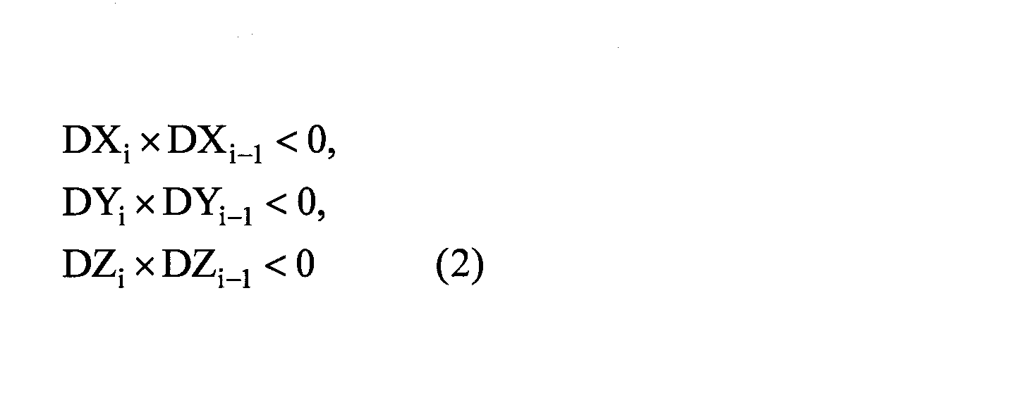
このようにポインタ130Aの位置が往復する動作は、利用者が意図的に行っている動作ではなく、ポインタ130Aを目標点に移動させようとして操作端末機130を移動させているときに、操作端末機130を持つ手がふらつくこと等によって生じる往復動作である。
また、このようにポインタ130Aを目標点に移動させるために利用者が操作端末機130を移動させているときには、ポインタ130Aの位置が往復するとは限らず、ポインタ130Aの移動方向が大きく変化する場合も有り得る。移動方向が大きく変化するとは、例えば、移動方向のX、Y、Z成分のうちの少なくともいずれか1つが反転することである。
このように利用者が目標点にポインタ130Aを移動させるために操作端末機130を繰り返し移動させていることを検出するために、判定部122は、ポインタ130Aの位置の移動距離が所定距離L未満であって、ポインタ130Aの位置の移動方向が所定回数にわたって変化したかどうかを判定する。
移動距離は、ポインタ130Aの移動方向が一度変化してから、ポインタ130Aの移動方向が次に変化するまでの移動距離である。
なお、所定距離Lは、利用者が意図的に行っている動作を排除するために、手のふらつき等によって生じうる距離よりも長く設定すればよく、実験等で求めた値に設定すればよい。このため、一例として、所定距離Lを10センチに設定する。
判定部123は、位置検出部121によって検出されるポインタ130Aの座標の時間的な変化によって得られる軌跡を監視し、軌跡が予め定められた所定の条件を満たすかどうかを判定する。判定部123は、第2判定部の一例である。
より具体的には、判定部123は、位置検出部121によって検出されるポインタ130Aの位置の時間的な変化に基づき、ポインタ130Aの位置の移動距離が所定距離L以上であって、移動方向が所定回数にわたって変化したかどうかを判定する。
ここで、所定回数は、N2回である。判定部123がカウントするN2回は、判定部122がカウントするN1回とは異なる。また、判定部123は、判定部122と同様の判定手法で、移動方向が変化したかどうかを判定する。
判定部123が判定する処理は、ポインタ130Aが所定距離L以上移動し、かつ、移動方向が変化することが、N2回以上生じたかどうかを判定する処理である。
すなわち、判定部123は、ポインタ130Aの移動方向が変化せずに、ポインタ130Aが所定距離L以上移動してから移動方向が変化することが、所定回数生じるたかどうかを判定する。
ここで、判定部123がポインタ130Aの移動方向が変化したかどうかを判定する判定処理は、判定部122の判定処理におけるポインタ130Aの移動方向が変化したかどうかを判定する処理と同様である。
従って、判定部123の判定処理において、移動方向が変化しないこととは、判定部122の判定処理と同様に、上述した移動方向の変化に該当しないことである。
また、判定部123は、操作端末機130の移動量に対するポインタ130Aの移動量を表す感度が低下されたのちに、感度を復帰させるかどうかを判定するために、上述の判定処理を行う。
ここで、シミュレーションシステム100では、感度を復帰させるためには、操作端末機130を操作することによって、ポインタ130Aを所定距離L以上移動させ、かつ、ポインタ130Aの移動方向を反転させる操作をN2回以上繰り返すと、感度を復帰させることができるように設定されている。
このため、所定距離Lは、利用者がポインタ130Aを目標点に移動させているときに、手がふれるようなことによってポインタ130Aが移動しうる距離よりも長く設定しておけばよい。このような所定距離Lは、例えば、実験等で求めた値に設定すればよく、一例として、10センチである。
従って、利用者には、ポインタ130Aを10センチ以上移動させて、かつ、10センチ以上移動させた後に移動方向を反転することをN2回以上繰り返すように、操作端末機130を移動させれば、感度を復帰させることができることを知らせておけばよい。なお、N2回は、例えば、3回である。
補正処理部124は、判定部122によって、ポインタ130Aの位置の移動距離が所定距離L未満であって、ポインタ130Aの位置の移動方向が所定回数にわたって変化したと判定されると、操作端末機130の移動量に対するポインタ130Aの移動量を表す感度を低下させる。
操作端末機130の移動量に対するポインタ130Aの移動量を表す感度を低下させることは、換言すれば、操作端末機130の移動量に対するポインタ130Aの移動量を相対的に低下させることである。
具体的には、補正処理部124は、次のような補正処理を行うことにより、操作端末機130の移動量に対するポインタ130Aの移動量を表す感度を低下させる。ここで、ポインタ130Aの移動量を表す感度をS(%)とする。感度S(%)は、補正処理部124による補正処理が行われていない状態では、基準値であり、100%であることとする。なお、基準値は、利用者の好み等によって設定された値である。
補正処理部124は、現フレームでのポインタ130Aの座標(Xi,Yi,Zi)を座標(Xai,Yai,Zai)に補正する。具体的には、次式(3)を用いて、感度S(%)を100(%)未満の値に設定することによってポインタ130Aの座標を補正する。
補正処理部124は、現フレームでのポインタ130Aの座標(Xi,Yi,Zi)を座標(Xai,Yai,Zai)に補正する。具体的には、次式(3)を用いて、感度S(%)を100(%)未満の値に設定することによってポインタ130Aの座標を補正する。
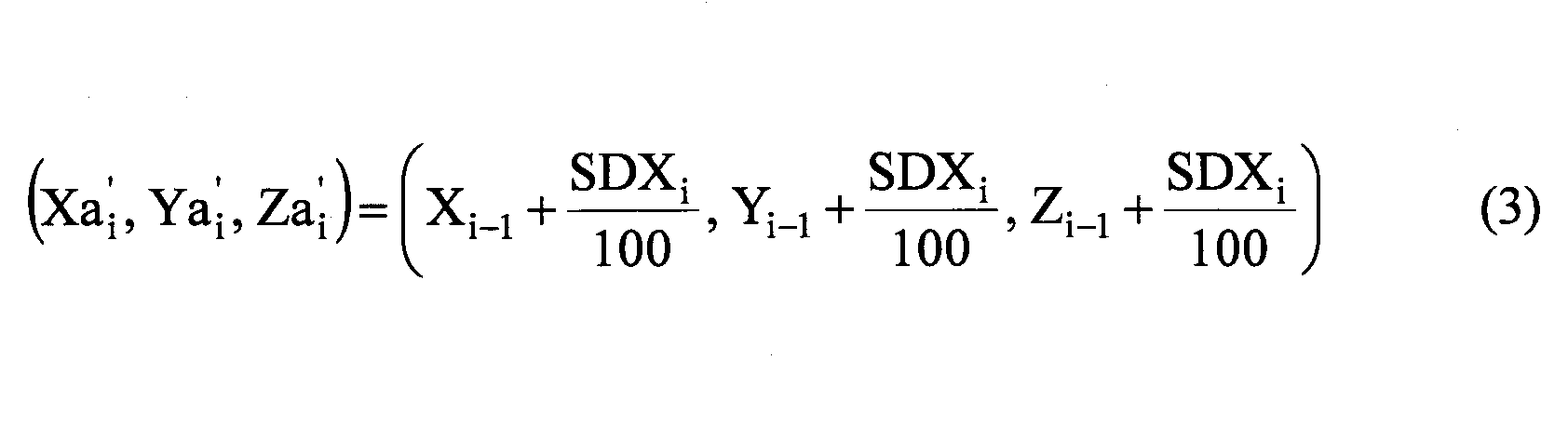
また、補正処理部124は、操作端末機130の移動量に対するポインタ130Aの移動量を表す感度が低下されている状態で、判定部123によって、ポインタ130Aの位置の移動距離が所定距離L以上であって、移動方向が所定回数にわたって変化したと判定されると、操作端末機130の移動量に対するポインタ130Aの移動量を表す感度を復帰させる。
具体的には、補正処理部124は、式(3)における感度S(%)を100(%)に戻すことによって、操作端末機130の移動量に対するポインタ130Aの移動量を表す感度を復帰させる。
映像出力部126の出力端子は、ケーブル110B1によって投影装置110Bに接続されている。映像出力部126は、データ保持部127に保持される物品111及び112の物品データによって特定される画像を投影装置110Bに出力し、スクリーン110Aに表示させる。
また、映像出力部126は、投影装置110Bにポインタ130Aを表示させる。スクリーン110Aに表示される画像内におけるポインタ130Aの位置は、補正処理部124によって補正されたポインタ130Aの座標に表示される。補正処理部124によって補正されたポインタ130Aの座標は、位置検出部121で検出される操作端末機130の位置と姿勢とによって決まるポインタ130Aの補正前の座標を補正したものである。映像出力部126は、表示制御部の一例である。
データ保持部127は、物品111及び112の座標と形状を表す物品データ、物品111及び112の触感に応じた振動パターンを表す振動データ、及びポインタ130Aの画像データ等のデータを保持する。データ保持部127は、メモリによって実現され、データ格納部の一例である。
駆動制御部128は、判定部122によって、ポインタ130Aの位置の移動距離が所定距離L未満であって、ポインタ130Aの位置の移動方向が所定回数にわたって変化したと判定されると、所定の振動パターンの駆動信号を出力する。この駆動信号は、操作端末機130の振動素子を駆動する信号である。
通信部129は、操作端末機130と無線通信を行う通信部であり、例えば、Bluetooth(登録商標)又はWiFi(Wireless Fidelity)等の規格で無線通信を行うことができる。通信部129は、駆動制御部128によって生成される駆動信号を操作端末機130に送信する。なお、通信部129は、操作端末機130と有線通信を行う通信部であってもよい。
操作端末機130は、シミュレーションシステム100を利用する利用者が手に保持し、スクリーン110Aに表示されるポインタ130Aの位置をコントロールする端末機である。操作端末機130は、マーカ132と振動素子133とを有する。
マーカ132は、複数の球体を有し、位置計測装置140から照射される赤外線を様々な方向に反射させる。マーカ132は、位置計測装置140による操作端末機130の位置検出に用いられる。
振動素子133は、操作端末機130に振動を発生させるために設けられている。また、振動素子133は、駆動制御部128によって生成される駆動信号によって駆動される。振動素子133は、可動素子の一例である。
なお、操作端末機130の詳細については後述する。
位置計測装置140は、赤外線カメラ140A、140B、及び140Cを有し、それぞれ、ケーブル141A、141B、及び141Cによって位置検出部121に接続されている。赤外線カメラ140A、140B、及び140Cは、操作端末機130に赤外線を照射し、マーカ132で反射された反射光を撮影する。位置計測装置140は、赤外線カメラ140A、140B、及び140Cが出力する画像データを位置検出部121に転送する。位置計測装置140は、第1検出部の一例である。
図3は、実施の形態1の処理装置120が適用されるコンピュータシステムの斜視図である。図3に示すコンピュータシステム10は、本体部11、ディスプレイ12、キーボード13、マウス14、及びモデム15を含む。
本体部11は、CPU(Central Processing Unit:中央演算装置)、HDD(Hard Disk Drive:ハードディスクドライブ)、及びディスクドライブ等を内蔵する。ディスプレイ12は、本体部11からの指示により画面12A上に解析結果等を表示する。ディスプレイ12は、例えば、液晶モニタであればよい。キーボード13は、コンピュータシステム10に種々の情報を入力するための入力部である。マウス14は、ディスプレイ12の画面12A上の任意の位置を指定する入力部である。モデム15は、外部のデータベース等にアクセスして他のコンピュータシステムに記憶されているプログラム等をダウンロードする。
コンピュータシステム10に処理装置120としての機能を持たせるプログラムは、ディスク17等の可搬型記録媒体に格納されるか、モデム15等の通信装置を使って他のコンピュータシステムの記録媒体16からダウンロードされ、コンピュータシステム10に入力されてコンパイルされる。
コンピュータシステム10に処理装置120としての機能を持たせるプログラムは、コンピュータシステム10を処理装置120として動作させる。このプログラムは、例えばディスク17等のコンピュータ読み取り可能な記録媒体に格納されていてもよい。コンピュータ読み取り可能な記録媒体は、ディスク17、ICカードメモリ、フロッピー(登録商標)ディスク等の磁気ディスク、光磁気ディスク、CD-ROM、USB(Universal Serial Bus)メモリ等の可搬型記録媒体に限定されるものではない。コンピュータ読み取り可能な記録媒体は、モデム15又はLAN等の通信装置を介して接続されるコンピュータシステムでアクセス可能な各種記録媒体を含む。
図4は、コンピュータシステム10の本体部11内の要部の構成を説明するブロック図である。本体部11は、バス20によって接続されたCPU21、RAM又はROM等を含むメモリ部22、ディスク17用のディスクドライブ23、及びハードディスクドライブ(HDD)24を含む。実施の形態1では、ディスプレイ12、キーボード13、及びマウス14は、バス20を介してCPU21に接続されているが、これらはCPU21に直接的に接続されていてもよい。また、ディスプレイ12は、入出力画像データの処理を行う周知のグラフィックインタフェース(図示せず)を介してCPU21に接続されていてもよい。
コンピュータシステム10において、キーボード13及びマウス14は、処理装置120の入力部である。ディスプレイ12は、処理装置120に対する入力内容等を画面12A上に表示する表示部である。
なお、コンピュータシステム10は、図3及び図4に示す構成のものに限定されず、各種周知の要素を付加してもよく、又は代替的に用いてもよい。
図5は、操作端末機130を示す斜視図である。
操作端末機130は、筐体131、マーカ132、振動素子133、ボタン134A、134B、及びガイドバー135を有する。
操作端末機130は、ポインタ130Aの位置の指標となるガイドバー135をスクリーン110Aに向けて利用者が手で持ち、操作端末機130の位置を前後、左右、上下に移動させることにより、スクリーン110Aに表示されるポインタ130Aを前後、左右、上下に移動させることができる端末機である。
また、以下では、左右を表す場合には、ガイドバー135をスクリーン110Aに向けて操作端末機130を保持し、スクリーン110Aを向く利用者を基準に左右の位置関係を表すこととする。
また、以下では、前後を表す場合には、ガイドバー135をスクリーン110Aに向けて操作端末機130を保持し、スクリーン110Aを向く利用者を基準に前後の位置関係を表すこととする。
また、筐体131の振動素子133が設けられる面を上面と称し、ガイドバー135が取り付けられる側を前側と称す。
筐体131は、例えば、樹脂製であり、利用者が手に持つのにちょうど良いサイズを有する。筐体131の上面には、振動素子133が配設されている。
マーカ132は、複数の球体132Aとワイヤ132Bとを有する。複数の球体132Aは、ワイヤ132Bによって筐体131に取り付けられている。
マーカ132は、位置計測装置140による操作端末機130の位置と姿勢の検出に用いられるため、位置計測装置140から照射される赤外線を様々な方向に反射させる。マーカ132が反射する赤外線は、赤外線カメラ140A及び140Bによって撮像され、位置検出部121が画像処理を行うことによってマーカ132の位置と姿勢が検出される。マーカ132の位置と姿勢は、操作端末機130の位置と姿勢を表す。
マーカ132は、規則性がない様々な方向に赤外線を反射できれば、球体の個数は幾つであってもよく、球体の位置についても特に限定はない。また、球体ではなくてもよいし、マーカ132の検出は、赤外線を用いる手法に限られない。操作端末機130の位置検出を行うことができるのであれば、マーカ132はどのようなものであってもよい。
振動素子133は、筐体131の上面に設けられている。振動素子133は、駆動制御部128によって生成される駆動信号によって駆動される。
振動素子133は、例えば、ピエゾ素子又はLRA(Linear Resonant Actuator)のような振動を発生する素子であればよい。振動素子133を駆動すると振動が発生する。
ボタン134A、134Bは、操作端末機130の様々な機能を実行する際に操作する押しボタンスイッチである。機能としては、例えば、処理装置120との無線通信のオン/オフを切り替える機能、ポインタ130Aの表示の明るさを調整する機能等の様々な機能である。
ガイドバー135は、筐体131の前側に取り付けられている。ガイドバー135は、ポインタ130Aの位置の指標となる部材であり、スクリーン110Aにポインタ130Aが表示される位置を認識しやすくするために設けられている。ガイドバー135は、ここでは、一例として、細長い三角形状の板状部材である。
ガイドバー135は、操作端末機130を手に持つ利用者が、スクリーン110Aに表示されるポインタ130Aの位置を移動させる際の指標又は基準点になるのであれば、どのような形状のものであってもよい。
なお、ガイドバー135がなくても、利用者がポインタ130Aの位置を把握しやすいような場合には、操作端末機130は、ガイドバー135を含まなくてもよい。
図6は、振動モータ133Aを示す図である。振動モータ133Aは、ベース133A1と、回転部133A2とを有する。ベース133A1の内部には、巻線コイルが設けられている。回転部133A2は、偏心構造を有し、回転するとベース133A1に振動が伝達する。このような振動モータ133Aを図5に示す振動素子133の代わりに用いてもよい。
図7は、操作端末機130の電気系の構成を示す図である。ここでは、筐体131とガイドバー135を簡略化して示し、マーカ132、振動素子133を省略する。
操作端末機130は、振動素子133、ボタン134A、134B、通信部136、ボタン判定部137、及び信号生成部138を有する。なお、ボタン判定部137と信号生成部138は、例えば、マイクロコンピュータのような演算処理装置によって実現される。
通信部136には、ボタン判定部137及び信号生成部138が接続されている。通信部136は、処理装置120の通信部129と無線通信を行う通信部であり、例えば、Bluetooth, WiFi, Xbee, zigbee等の規格で無線通信を行う。
通信部136は、ボタン判定部137から入力される信号を処理装置120に送信する。また、通信部136は、処理装置120の駆動制御部128によって生成される駆動信号を受信し、信号生成部138に出力する。
ボタン判定部137は、ボタン134Aの操作の有無と、ボタン134Bの操作の有無とを判定する判定部であり、例えば、処理装置120との無線通信のオン/オフ、ポインタ130Aの表示の明るさを調整等の操作内容を判定する。ボタン判定部137は、操作内容を表す信号を通信部136に出力する。
信号生成部138は、通信部136が受信する駆動信号を増幅して振動素子133を駆動する。なお、信号生成部138を駆動制御部として捉えてもよい。
図8は、判定部122及び123が各フレームにおいて取得するポインタ130Aの座標を表す図である。
図8に示すように、フレーム数iと、ポインタ130Aの座標(Xi,Yi,Zi)とが関連付けられて記録される。このようなポインタ130Aの座標は、データ保持部127によって保持される。
図9は、判定部122及び123と補正処理部124が利用するデータを示す図である。図9に示すデータは、データ保持部127によって保持される。
図9に示すデータは、判定部122が判定に利用する所定回数N1、距離L、判定部123が判定に利用する所定回数N2、補正処理部124が感度Sを低下させる際に利用する値Kを関連付けたデータである。判定部122及び123と補正処理部124が判定処理等に利用するデータは、データ保持部127によって保持される。
図10は、物品データを示す図である。
物品データは、スクリーン110Aに表示する物品の座標と形状を表すデータである。物品データは、物品ID、形状タイプ、基準座標、サイズ、及び回転角度を有する。
形状タイプは、物品の外形を表す。図10では、一例として、形状タイプがCuboid(直方体)とCylinder(円柱体)を示す。
基準座標は、物品の全体を表す座標の基準になる点の座標値を示す。座標値の単位はメートル(m)である。なお、座標系としては、XYZ座標系を用いる。このXYZ座標系は、スクリーン110Aに表示される画像の位置を表す仮想空間における座標系である。
サイズは、物品のX軸方向の長さ、Y軸方向の長さ、Z軸方向の長さを表す。単位はメートル(m)である。一例として、X軸方向の長さは縦の長さを表し、Y軸方向の長さは高さを表し、Z軸方向の長さは奥行き(横方向の長さ)を表す。
回転角度は、X軸方向、Y軸方向、Z軸方向に対する回転角度θx、θy、θzで表される。単位は度(deg.)である。回転角度θxは、X軸を回転軸として物品を回転させる角度である。同様に、回転角度θy及びθzは、それぞれ、Y軸及びZ軸を回転軸として物品を回転させる角度である。回転角度θx、θy、θzの正方向は、予め決めておけばよい。
このような物品データを用いれば、CADデータによって表示される物品の画像と同様に、物品データによって特定される画像を表すことができる。
なお、物品データは、処理装置120のデータ保持部127に格納されている。
図11は、物品の画像の一例を示す図である。
図11には、図10の物品データによって表される3つの物品を示す。
物品IDが001の物品は、形状タイプがCuboid(直方体)で、基準座標(X,Y,Z)が(0.0,0.0,0.0)であり、サイズが(0.8,0.2,0.4)であり、回転角度θx、θy、θzが(0.0,0.0,0.0)である。
基準座標(X,Y,Z)が(0.0,0.0,0.0)であるため、物品IDが001の物品の1つの頂点は、XYZ座標系の原点Oと一致している。
物品IDが002の物品は、形状タイプがCuboid(直方体)で、基準座標(X,Y,Z)が(0.6,0.2,0.0)であり、サイズが(0.2,0.2,0.1)であり、回転角度θx、θy、θzが(0.0,0.0,0.0)である。
このため、物品IDが002の物品は、物品IDが001の物品の上に配置されている。
物品IDが003の物品は、形状タイプがCylinder(円柱体)で、基準座標(X,Y,Z)が(0.8,0.3,0.1)であり、サイズが(0.2,1.0,0.3)であり、回転角度θx、θy、θzが(0.0,0.0,90.0)である。
このため、物品IDが003の物品は、Z軸を回転軸として90度回転させた状態で、物品IDが002の物品のX軸正方向側に接続されている。
なお、上述のように、実施の形態1では、図10に示す物品ID、形状タイプ、基準座標、サイズ、及び回転角度を有する物品データを用いて、スクリーン110Aに投影される画像の中における物品の座標と形状を規定する。
例えば、形状タイプがCuboid(直方体)の場合に、8つの頂点の座標は、基準座標に対して、サイズで表される物品のX軸方向の長さ、Y軸方向の長さ、Z軸方向の長さを加算又は減算することによって求めることができる。8つの頂点の座標は、形状タイプがCuboid(直方体)の物品のCorner(角)の座標を表す。
8つの頂点の座標を求めれば、12本の辺を表す式を求めることができる。12本の辺を表す式は、形状タイプがCuboid(直方体)の物品のEdge(辺)の座標を表す式である。
また、8つの頂点の座標、及び/又は、12本の辺を表す式を求めれば、形状タイプがCuboid(直方体)の物品の6つの表面を表す式が求まり、Surface(面)の座標を求めることができる。
また、形状タイプがCylinder(円柱体)の場合には、サイズで表される物品のX軸方向の長さ、Y軸方向の長さ、Z軸方向の長さに基づいて、円柱の両端にある円(又は楕円)を表す式を求めることができる。また、両端の円(又は楕円)を表す式と基準座標とを用いれば、両端の円(又は楕円)の座標を表す式を求めることができる。円柱体の側面の座標は、両端の円(又は楕円)の座標を表す式を用いることよって求めることができる。
ここでは、形状タイプがCuboid(直方体)とCylinder(円柱体)の物品について説明したが、球体、三角錐、凹部を有する直方体等の様々な形状の物品についても、同様にスクリーン110Aに投影される画像の中における座標と形状を求めることができる。
図12及び図13は、利用者がポインタ130Aを移動させているときにシミュレーションシステム100が感度Sを低下させる様子を示す図である。図12及び図13には、スクリーン110Aに表示される物品111とポインタ130Aを示す。
以下の説明では、物品111の8つの角のうち、角111A、111B、及び111Cを用いる。また、辺111E1、111E2、111E3、111E4と面111S1、111S2、111S3を示す。一例として、物品111は、1辺の長さが50cmの立方体状の物品である。
図12では、一例として、物品111の表示倍率Mは100%であり、操作端末機130の移動量に対するポインタ130Aの移動量を表す感度Sは100%である。
例えば、利用者がポインタ130Aを角111Bに移動させようとしているときに、ある瞬間では、手のふらつきによってポインタ130Aが角111Bと111Cの間で辺111E4の近傍にあることとする。
また、シミュレーションシステム100は、角111Bの座標の許容範囲130A1を設定している。許容範囲130A1は、角111Bを中心とし、所定の半径で規定される球状の領域である。許容範囲130A1の中にポインタ130Aがある場合には、ポインタ130Aは、角111Bにあるものとして取り扱われる。
許容範囲130A1の半径は5cmである。これは、一例として、物品111の1辺の長さ(50cm)の10%の長さである。すなわち、許容範囲130A1の直径は10cmである。
図12に示す状態では、利用者の手がふれることにより、ポインタ130Aは許容範囲130A1の中に収まっていない。このため、シミュレーションシステム100は、ポインタ130Aが角111Bにあるものとして取り扱っていない。
また、感度Sが100%の状態において、利用者の手がふれる範囲は、範囲130A2に及んでいることとする。範囲130A2は、角111Bを中心として、利用者の手がふれることによって、ポインタ130Aが角111Bから最も遠くなった場合のポインタ130Aの位置と角111Bとの間の距離を半径とする球状の領域である。
ここでは、図12に示すポインタ130Aの位置が、利用者の手のふれによってポインタ130Aが角111Bから最も遠くなった場合の位置であることとする。このため、範囲130A2の境界上にポインタ130Aが位置している。一例として、範囲130A2の半径は15cmである。すなわち、範囲130A2の直径は30cmである。
ここで、シミュレーションシステム100が感度Sを25%まで低下させたとする。このような場合には、ポインタ130Aの移動量の感度が1/4にされることになる。ここで、感度Sを低下させた場合における手のふれの範囲を130A2Mとすると、範囲130A2Mの直径は7.5cmになり、図13に示すように、ポインタ130Aは、許容範囲130A1の内部に収まることになる。
このようにポインタ130Aが許容範囲130A1の内部に収まれば、シミュレーションシステム100によって、ポインタ130Aは、角111Bにあるものとして取り扱われる。
従って、利用者は、ポインタ130Aを容易に角111Bに移動させることができるようになる。
シミュレーションシステム100は、上述のように感度Sを低下させるときに、所定の振動データを用いて振動素子133を駆動する。これにより、感度Sが低下されたことが利用者に触感で知らされることになる。
図14及び図15は、実施の形態1の処理装置120が実行する処理を示すフローチャートである。ここでは、一例として、スクリーン110A(図1参照)に物品111の画像を表示させる場合について説明する。
処理装置120は、電源投入後に処理を開始する(START)。
処理装置120は、判定部122が判定に利用する所定回数N1、距離L、判定部123が判定に利用する所定回数N2、補正処理部124が利用する値Kをデータ保持部127から読み出して設定する(ステップS1)。
所定回数N1と距離Lの設定は判定部122が行い、所定回数N2の設定は判定部123が行い、値Kの設定は補正処理部124が行う。値Kは、感度Sを低減する割合を表す値であり、ここでは一例として、75(%)である。
処理装置120は、感度Sを100%、表示倍率Mを100%、フレーム数iを1、カウント数n1、n2を0に設定する(ステップS2)。カウント数n1は、感度Sを低下させるまでに、ポインタ130Aの移動方向が変化する回数であり、カウント数n2は、感度Sを100%に復帰させるための所定の動作を利用者が行う場合にポインタ130Aの移動方向が変化する回数である。
感度Sの設定は判定部122が行い、表示倍率Mとフレーム数iの設定は映像出力部126が行い、カウント数n1の設定は判定部122が行い、カウント数n2の設定は判定部123が行う。
処理装置120は、操作端末機130の位置のキャリブレーションを行う(ステップS3)。キャリブレーションは、位置検出部121で検出する操作端末機130の初期の位置と、スクリーン110Aに表示される画像(仮想空間)の中におけるポインタ130Aの位置とを関連付ける処理である。位置検出部121は、キャリブレーションを行う機能を有する。このため、ステップS3の処理は、位置検出部121によって行われる。
処理装置120は、現フレームにおけるポインタ130Aの座標を取得する(ステップS4)。ポインタ130Aの座標は、位置検出部121が、操作端末機130の3次元座標における座標値をスクリーン110Aに投影される画像の中の座標に変換することによって得られる。
処理装置120は、ステップS4で取得したポインタ130Aの座標をデータ保持部127に記録する(ステップS5)。ステップS5の処理は、位置検出部121によって行われる。
処理装置120は、フレーム数iが1であるかどうかを判定する(ステップS6)。ステップS6の処理は、映像出力部126によって行われる。
処理装置120は、フレーム数iが1である(S6:YES)と判定すると、物品データをデータ保持部127から読み出す(ステップS7)。ステップS6の処理は、映像出力部126によって行われる。ここでは、利用者が物品111を選択し、映像出力部126が物品111の物品データをデータ保持部127から読み出すこととする。
処理装置120は、利用者によって選択された物品111をスクリーン110Aに表示する(ステップS8)。処理装置120は、物品データ(図10参照)から物品111のデータを読み出してスクリーン110Aに表示する。物品111の表示は、映像出力部126によって行われる。
処理装置120は、フレーム数iをインクリメントする(ステップS9)。ステップS9の処理は、映像出力部126によって行われる。
処理装置120は、処理の終了であるかどうかを判定する(ステップS10)。処理の終了は、操作端末機130でボタン134A又は134Bの操作で選択できることとする。
処理装置120は、処理の終了ではない(S10:NO)と判定すると、フローをステップS4にリターンする。また、処理装置120は、処理の終了が選択された(S10:YES)と判定すると、一連の処理を終了する(END)。
処理装置120は、ステップS6において、フレーム数iが1ではない(S6:NO)と判定すると、前フレームのポインタ130Aの座標をデータ保持部127から読み出す(ステップS11)。ステップS11の処理は、判定部122によって行われる。
処理装置120は、現フレームのポインタ130Aの座標と、前フレームのポインタ130Aの座標とに基づいて、現フレームにおけるポインタ130Aの移動量を算出する(ステップS12)。処理装置120は、式(1)を用いて現フレームにおけるポインタ130Aの移動量を算出する。ステップS12の処理は、判定部122によって行われる。
処理装置120は、ステップS12で算出した移動量をデータ保持部127に記録する(ステップS13)。ステップS13の処理は、判定部122によって行われる。
処理装置120は、前フレームのポインタ130Aの移動量をデータ保持部127から読み出す(ステップS14)。ステップS14の処理は、判定部122によって行われる。
処理装置120は、現フレームのポインタ130Aの移動量と、前フレームのポインタ130Aの移動量とに基づいて、ポインタ130Aの移動方向が変化しているかどうかを判定する(ステップS15)。
具体的には、処理装置120は、式(2)が表す3つの不等式のうちのいずれか1つが成立するかどうかを判定する。ステップS15の処理は、判定部122によって行われる。
処理装置120は、移動方向が変化している(S15:YES)と判定すると、変化時のポインタ130Aの座標をデータ保持部127に記録する(ステップS16)。変化時のポインタ130Aの座標は、現フレームにおけるポインタ130Aの座標である。ステップS16の処理は、判定部122によって行われる。
処理装置120は、移動方向の変化が初めてであるかどうかを判定する(ステップS17)。処理装置120は、移動方向の変化が初めてであるかどうかを、変化時のポインタ130Aの座標がデータ保持部127に記録されているかどうかで判定すればよい。ステップS17の処理は、判定部122によって行われる。
処理装置120は、移動方向の変化が初めてではない(S17:NO)と判定すると、今回の変化時のポインタ130Aの座標と、前回の変化時のポインタ130Aの座標との間の移動距離を算出する(ステップS18)。ステップS18の処理は、判定部122によって行われる。
処理装置120は、ステップS18で求めた移動距離が所定距離L未満であるかどうかを判定する(ステップS19)。ステップS19の処理は、判定部122によって行われる。
処理装置120は、移動距離が所定距離L未満である(S19:YES)と判定すると、ポインタ130Aの移動距離がL未満の場合に移動方向が変化する回数であるカウント数n1をインクリメントする(ステップS20)。ステップS20の処理は、判定部122によって行われる。
処理装置120は、カウント数n1が所定回数N1回と等しいかどうかを判定する(ステップS21)。ステップS21の処理は、判定部122によって行われる。
処理装置120は、カウント数n1が所定回数N1回と等しくない(S21:NO)と判定すると、フローをステップS24に進行させる。
処理装置120は、カウント数n1が所定回数N1回と等しい(S21:YES)と判定すると、駆動信号を操作端末機130に送信する(ステップS22)。駆動信号は、駆動制御部128が通信部129を介して操作端末機130に送信する。
これにより、操作端末機130の振動素子133が駆動され、利用者の手に振動が伝わり、利用者は、ポインタ130Aの移動量の感度が低下されることを認識する。なお、ステップS21の処理は、判定部122が駆動制御部128に駆動信号を送信させることによって行われる。
処理装置120は、感度SをKだけ低下させる(ステップS23)。すなわち、低下後の感度はS-K(%)となる。例えば、Kが75(%)の場合は、低下後の感度Sは25%になる。ステップS23の処理は、判定部122が補正処理部124に感度Sを低下させることよって行われる。
処理装置120は、感度Sに基づいてポインタ130Aの座標を補正する(ステップS24)。ステップS23の処理は、補正処理部124が式(3)を用いてポインタ130Aの座標を補正することによって行われる。なお、感度Sが低減されずに100(%)の状態では、式(3)においてSが100(%)の状態で補正が行われる。換言すれば、この場合には、ポインタ130Aの座標は変化しない。
処理装置120は、ステップS24の処理が終了すると、フローをステップS7にリターンする。
なお、処理装置120は、ステップS15において、移動方向が変化していない(S15:NO)と判定すると、フローをステップS24に進行させる。移動方向が変化していない場合には、ステップS16乃至S23の処理を行う必要がないからである。
また、処理装置120は、ステップS17において、移動方向の変化が初めてである(S17:YES)と判定すると、フローをステップS24に進行させる。移動方向の変化が初めてであるには、前回の変化時の座標が存在せず、移動距離を計算できないからである。
ステップS4からステップS6を経て、さらにステップS11からステップS15に至るループがN1回(3回)だけ繰り返されることによって、移動方向が変化した回数を表すカウント数n1がN1と等しくなると、ステップS23で感度SがKだけ低下されることになる。
処理装置120は、移動距離が所定距離L未満ではない(S19:NO)と判定すると、ポインタ130Aの移動距離がL以上の場合に移動方向が変化する回数であるカウント数n2をインクリメントする(ステップS25)。ステップS25の処理は、判定部123によって行われる。
移動距離が所定距離L未満ではない(S19:NO)と判定される場合は、感度Sが低下された後に、感度Sを100%に復帰させるための所定の動作が利用者によって行われている場合である。
処理装置120は、カウント数n2が所定回数N2回と等しいかどうかを判定する(ステップS26)。ステップS26の処理は、判定部123によって行われる。
処理装置120は、カウント数n2が所定回数N2回と等しくない(S26:NO)と判定すると、フローをステップS24に進行させる。カウント数n2が所定回数N2回に到達するまでは、感度Sを復帰させないからである。
処理装置120は、カウント数n2が所定回数N2回と等しい(S26:YES)と判定すると、感度Sを100(%)に復帰させる(ステップS27)。具体的には、判定部123が補正処理部124に感度Sを100(%)に復帰させるトリガー信号を送信することよって、補正処理部124によって感度Sが100(%)に戻される。
処理装置120は、ステップS27の処理を終えると、フローをステップS24に進行させる。
処理装置120は、ステップS10で終了と判定するまで、以上の処理を繰り返し実行する。
この結果、利用者の手がふれることによって、ポインタ130Aの移動距離が所定距離L未満で、移動方向がN1回(3回)変化すると、ポインタ130Aの感度Sが1/4に低減され、図12に示す手のふれの範囲130A2が図13に示す手のふれの範囲130A2Mに縮小される。手のふれの範囲130A2Mの直径は、手のふれの範囲130A2の直径の1/4である。
このため、利用者は、ポインタ130Aを狙った位置に移動させやすくなる。
従って、実施の形態1によれば、容易に操作できるシミュレーションシステム100を提供することができる。
また、感度Sが低下された状態で、操作端末機130を10センチ以上、かつ、5回以上繰り返して移動方向を変えるように移動させれば、感度Sを100(%)に復帰させることができるので、感度Sの復帰を容易に行うことができる。
なお、以上では、ポインタ130Aの感度Sを低減することによって、利用者がポインタ130Aを狙った位置に移動させやすくする形態について説明した。
しかしながら、ポインタ130Aの感度Sを100%に保持した状態で、物品111の画像の表示倍率Mを増大させても、同様にポインタ130Aを狙った位置に移動させやすくなる。これは、ポインタ130Aの感度Sが相対的に低減されるからである。
具体的には、図16及び図17に示すフローチャートの通りである。ここでは、補正処理部124が表示倍率Mを補正する。
図16及び図17は、実施の形態1の変形例による処理を示すフローチャートである。図16及び図17に示す処理は、実施の形態1のフローチャートのステップS23とS27をS23AとS27Aに入れ替えるとともに、ステップS24を削除した内容になっている。
ステップS23Aにおいて、処理装置120は、表示倍率MをK2だけ増大させる(ステップS23A)。ここで、K2は300(%)であることとする。増大後の表示倍率MはM+K2(%)で400(%)になる。ステップS23Aの処理は、判定部122が補正処理部124に表示倍率Mを増大させることよって行われる。
ステップS27Aにおいて、処理装置120は、カウント数n2が所定回数N2回と等しい(S26:YES)と判定すると、表示倍率Mを100(%)に復帰させる(ステップS27A)。具体的には、判定部123が補正処理部124に表示倍率Mを100(%)に復帰させるトリガー信号を送信することよって、補正処理部124によって表示倍率Mが100(%)に戻される。
図16及び図17に示す処理では、ステップS15でNO、ステップS17でYES、ステップS21でNO、ステップS26でNOになった場合と、ステップS23A及びステップS27Aが終了した場合に、ステップS7に進行することになる。
図18は、物品111の表示倍率Mを増大させた状態のスクリーン110Aの画像を示す図である。
物品111は、表示倍率Mが400(%)に増大されることにより、各辺の長さが4倍になっている。これに伴い、許容範囲130A1の直径も4倍になっている。
この結果、利用者の手がふれる範囲130A2は、物品111及び許容範囲130A1に比べて、相対的に1/4になっている。
このため、ポインタ130Aの感度Sを1/4にしたときと同様に、手がふれる範囲130A2は、許容範囲130A1の中に収まっており、利用者は、ポインタ130Aを狙った位置に移動させやすくなる。
従って、実施の形態1の変形例によれば、容易に操作できるシミュレーションシステム100を提供することができる。
<実施の形態2>
図19は、実施の形態2の処理装置120Bの内部構成を示す図である。
図19は、実施の形態2の処理装置120Bの内部構成を示す図である。
処理装置120Bは、位置検出部121、判定部122B、判定部123、補正処理部124、積算部125、映像出力部126、データ保持部127、駆動制御部128、及び通信部129を有する。処理装置120Bは、例えば、メモリを有するコンピュータによって実現される。
処理装置120Bは、実施の形態1の処理装置120の判定部122を判定部122Bに置き換えて、積算部125を追加した構成を有する。以下では、実施の形態1の処理装置120と同様の構成要素には同一符号を付し、その説明を省略する。
判定部122Bは、感度Sを低下させる手法が実施の形態1の判定部122と異なる。なお、実施の形態2では、補正処理部124が設定するKは500(%)である。
図20及び図21は、実施の形態2の処理装置120Bが実行する処理を示すフローチャートである。ここでは、一例として、スクリーン110A(図1参照)に物品111の画像を表示させる場合について説明する。
図20及び図21に示す処理は、実施の形態1のステップS1、S2、S23をそれぞれ、S1B、S2B、S23Bに置き換え、ステップS15でNOと判定した場合にステップS15Bを追加し、ステップS24の前にステップS24Bを追加した内容になっている。以下、相違点を中心に説明する。
処理装置120Bは、処理を開始(START)させると、判定部122Bが判定に利用する所定回数N1、距離L、判定部123が判定に利用する所定回数N2、補正処理部124が利用する値Kをデータ保持部127から読み出して設定する(ステップS1B)。
所定回数N1と距離Lの設定は判定部122Bが行い、所定回数N2の設定は判定部123が行い、値Kの設定は補正処理部124が行う。値Kは、感度Sを低減する割合を表す値であり、ここでは一例として、500(%)である。
処理装置120Bは、感度Sを100%、表示倍率Mを100%、ポインタ130Aの移動距離の積算値I、フレーム数iを1、カウント数n1、n2を0に設定する(ステップS2B)。
ポインタ130Aの移動距離の積算値Iは、ポインタ130Aが移動した距離を積算した値を示す。
感度Sの設定は判定部122Bが行い、表示倍率Mとフレーム数iの設定は映像出力部126が行い、カウント数n1の設定は判定部122Bが行い、カウント数n2の設定は判定部123が行う。積算値Iの設定は、積算部125が行う。
処理装置120Bは、ステップS3からステップS15の処理を行い、ステップS15において、移動方向が変化していない(S15:NO)と判定すると、フローをステップS15Bに進行させる。
処理装置120は、カウント数n1が0であるかどうかを判定する(ステップS15B)。処理装置120は、カウント数n1が0ではない(S15B:NO)場合は、フローをステップS24Bに進行させる。
処理装置120は、ステップS23Bにおいて、感度SをKIだけ低下させる(ステップS23B)。すなわち、低下後の感度はS-KI(%)となる。例えば、Kが500(%)で、ポインタ130Aの移動距離の積算値Iが0.15(m)の場合は、KIは75(%)であり、低下後の感度Sは25%になる。ステップS23Bの処理は、判定部122が補正処理部124に感度Sを低下させることよって行われる。
なお、ステップS23Bでは、積算値Iをメートル単位で表した場合の数値だけをKに乗算する。
処理装置120は、ステップS23Bが終了すると、フローをステップS24Bに進行させる。
処理装置120は、現フレームのポインタ130Aの移動量を積算値Iに加算することにより、積算値Iを更新する(ステップS24B)。このようにして、ステップS24Bでは、ポインタ130Aの移動距離が積算される。ステップS24Bの処理は、積算部125によって行われる。
処理装置120は、ステップS24Bが終了すると、フローをステップS24に進行させる。
処理装置120は、カウント数n1が0であって(S15B:YES)、ポインタ130Aの移動方向が変化していない場合には、積算値Iを更新する必要がないからである。
処理装置120Bは、ステップS10で終了と判定するまで、以上の処理を繰り返し実行する。
この結果、利用者の手がふれることによって、ポインタ130Aの移動距離が所定距離L未満で、移動方向がN1回(3回)変化すると、ポインタ130Aの感度Sが1/4に低減され、図12に示す手のふれの範囲130A2が図13に示す手のふれの範囲130A2Mに縮小される。手のふれの範囲130A2Mの直径は、手のふれの範囲130A2の直径の1/4である。
このため、利用者は、ポインタ130Aを狙った位置に移動させやすくなる。
従って、実施の形態2によれば、容易に操作できるシミュレーションシステム100を提供することができる。
なお、以上では、ポインタ130Aの感度Sを低減することによって、利用者がポインタ130Aを狙った位置に移動させやすくする形態について説明した。
しかしながら、ポインタ130Aの感度Sを100%に保持した状態で、物品111の画像の表示倍率Mを増大させても、同様にポインタ130Aを狙った位置に移動させやすくなる。これは、ポインタ130Aの感度Sが相対的に低減されるからである。
具体的には、実施の形態1の図14及び図15に示す処理を実施の形態2の図20及び図21に示す処理に変形したように、積算値Iを考慮した内容にして、その上で物品111の表示倍率Mを増大する際に、表示倍率MをK2×Iだけ増大させるようにすればよい。K2の値は、実施の形態1のK(75(%))を500(%)に変更したように、適切な値に設定すればよい。例えば、K2を2000に設定し、Iが0.15(m)であれば、K2×Iは300(%)になるので、表示倍率Mを400(%)にすることができる。
このように、実施の形態2においても、物品111の表示倍率Mを増大させることによって、操作性を改善してもよい。
<実施の形態3>
図22は、実施の形態3の処理装置120Cの内部構成を示す図である。
図22は、実施の形態3の処理装置120Cの内部構成を示す図である。
処理装置120Cは、位置検出部121、判定部122C、判定部123、補正処理部124、記録部125C、映像出力部126、データ保持部127、駆動制御部128、及び通信部129を有する。処理装置120Cは、例えば、メモリを有するコンピュータによって実現される。
処理装置120Cは、実施の形態1の処理装置120の判定部122を判定部122Cに置き換えて、記録部125Cを追加した構成を有する。以下では、実施の形態1の処理装置120と同様の構成要素には同一符号を付し、その説明を省略する。
判定部122Cは、感度Sを低下させる手法が実施の形態1の判定部122と異なる。なお、実施の形態3では、補正処理部124が設定するKは2.77×10⁶(%)である。
図23及び図24は、実施の形態3の処理装置120Cが実行する処理を示すフローチャートである。図25は、処理装置120Cが取得するポインタ130Aの座標を表すデータを示す図である。ここでは、一例として、スクリーン110A(図1参照)に物品111の画像を表示させる場合について説明する。
図23及び図24に示す処理は、実施の形態1のステップS19とS20の間にステップS20Cを挿入し、実施の形態1のステップS21とS22の間にステップS22Cを挿入し、実施の形態1のステップS23をS23Cに置き換えた内容になっている。以下、相違点を中心に説明する。
処理装置120Cは、処理を開始(START)させると、ステップS1からS19の処理を実行する。これらの処理は、実施の形態1と同様である。
処理装置120は、移動距離が所定距離L未満である(S19:YES)と判定すると、ポインタ130Aの移動範囲を更新する(ステップS20C)。実施の形態3では、ポインタ130Aの座標を記録することにより、ポインタ130Aが移動した際の軌跡を含む三次元空間を移動範囲として記録する。ステップS20Cの処理は、記録部125Cが行う。
ポインタ130Aの座標は、図25に示すように、カウント数n1と、ポインタ130Aの座標値(X,Y,Z)を関連付けたデータである。このようなポインタ130Aの座標から、次のようにして移動範囲を求める。
例えば、ポインタ130Aの座標の最大値を(Xmax,Ymax,Zmax)とし、最小値を(Xmin,Ymin,Zmin)とすると、移動範囲は以下の式(4)で表される。


処理装置120は、ステップS20Cの処理を終えると、カウント数n1をインクリメントする(ステップS20)。ステップS20の処理は、判定部122によって行われる。
処理装置120は、カウント数n1が所定回数N1回と等しい(S21:YES)と判定すると、パラメータPを取得する(ステップS22C)。パラメータPは、次のようにして求める。ステップS22Cの処理は、記録部125Cが行う。
一例として、パラメータPは移動範囲の各方向にα(m)の余裕を持たせた範囲の直方体の体積Vとする。ポインタ130Aの座標の最大値を(Xmax,Ymax,Zmax)、最小値を(Xmin,Ymin,Zmin)とすると、Vは、次式(6)で表される。
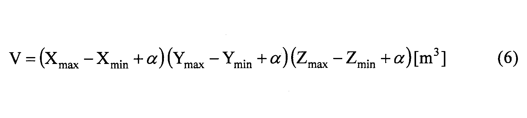
なお、ここでは、パラメータPとして、移動範囲の各方向にα(m)の余裕を持たせた範囲の直方体の体積Vを用いるが、余裕α(m)を持たせずに、移動範囲を表す領域の体積であってもよい。
処理装置120は、ステップS22の処理を終えると、感度SをK×Pだけ低下させる(ステップS23C)。すなわち、低下後の感度はS-KP(%)となる。例えば、Kが2.77×10⁶(%)で、Pが2.7×10⁻⁵(m3)の場合は、低下後の感度Sは25%になる。ステップS23Cの処理は、記録部125Cが求めるパラメータPに基づいて、判定部122が補正処理部124に感度SをK×Pだけ低下させることよって行われる。
処理装置120は、ステップS23Cが終了すると、フローをステップS24に進行させる。
処理装置120Cは、ステップS10で終了と判定するまで、以上の処理を繰り返し実行する。
この結果、利用者の手がふれることによって、ポインタ130Aの移動距離が所定距離L未満で、移動方向がN1回(3回)変化すると、ポインタ130Aの感度Sが1/4に低減され、図12に示す手のふれの範囲130A2が図13に示す手のふれの範囲130A2Mに縮小される。手のふれの範囲130A2Mの直径は、手のふれの範囲130A2の直径の1/4である。
このため、利用者は、ポインタ130Aを狙った位置に移動させやすくなる。
従って、実施の形態3によれば、容易に操作できるシミュレーションシステム100を提供することができる。
なお、以上では、ポインタ130Aの感度Sを低減することによって、利用者がポインタ130Aを狙った位置に移動させやすくする形態について説明した。
しかしながら、ポインタ130Aの感度Sを100%に保持した状態で、物品111の画像の表示倍率Mを増大させても、同様にポインタ130Aを狙った位置に移動させやすくなる。これは、ポインタ130Aの感度Sが相対的に低減されるからである。
具体的には、実施の形態1の図14及び図15に示す処理を実施の形態3の図23及び図24に示す処理に変形したように、積算値Iを考慮した内容にして、その上で物品111の表示倍率Mを増大する際に、表示倍率MをK2×Iだけ増大させるようにすればよい。K2の値は、実施の形態1のK(75(%))を2.77×10⁶(%)に変更したように、適切な値に設定すればよい。例えば、K2を1.85×10⁷に設定し、Iが0.15(m)であれば、K2×Iは300(%)になるので、表示倍率Mを400(%)にすることができる。
このように、実施の形態3においても、物品111の表示倍率Mを増大させることによって、操作性を改善してもよい。
なお、パラメータPとして、体積Vの直方体の中にあるポインタ130Aの移動軌跡の空間的な密度ρを用いてもよい。密度ρは、次式(7)で求めることができる。
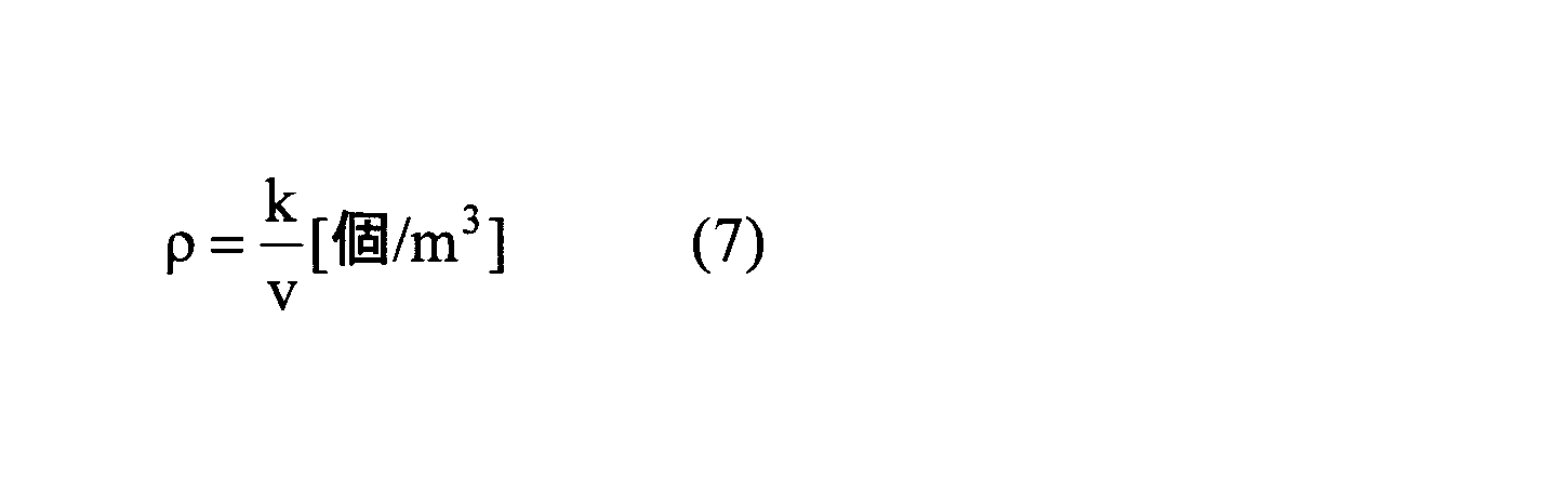
<実施の形態4>
実施の形態4は、実施の形態1における感度Sの復帰を操作端末機130のボタン134Aを押すことで実現するものである。このため、シミュレーションシステム100の装置構成は、実施の形態1と同様である。以下、処理装置120が実行する処理について説明する。
実施の形態4は、実施の形態1における感度Sの復帰を操作端末機130のボタン134Aを押すことで実現するものである。このため、シミュレーションシステム100の装置構成は、実施の形態1と同様である。以下、処理装置120が実行する処理について説明する。
図26及び図27は、実施の形態4の処理装置120が実行する処理を示すフローチャートである。ここでは、一例として、スクリーン110A(図1参照)に物品111の画像を表示させる場合について説明する。
図26及び図27に示す処理は、実施の形態1で図14及び図15に示したステップS2、S20、S21をそれぞれ、S2D、S20D、S21Dに置き換え、ステップS9とS10の間にステップS10D1及びS10D2を追加し、ステップS16からS19と、ステップS25からS27とを削除した内容になっている。以下、相違点を中心に説明する。
処理装置120は、処理を開始(START)させて、ステップS1の処理を終えると、感度Sを100%、表示倍率Mを100%、ポインタ130Aの移動距離の積算値I、フレーム数iを1、カウント数nを0に設定する(ステップS2D)。
カウント数nは、実施の形態1のカウント数n1と同様であり、判定部122Cが設定する。
処理装置120は、ステップS3からステップS9の処理を行い、ステップS10D1において、ボタン134Aが押されたかどうかを判定する(ステップS10D1)。ここでは、ボタン134Aは、感度Sを復帰させるために利用されるものとする。
処理装置120は、ボタン134Aが押された(S10D1:YES)と判定すると、感度Sを100(%)に復帰させる(ステップS10D2)。具体的には、ボタン134Aが押されたことを補正処理部124が検出すると、補正処理部124は、感度Sを100(%)に戻す。
処理装置120は、ステップS10D2の処理を終えると、フローをステップS10に進行させる。
処理装置120は、ボタン134Aが押されていない(S10D1:NO)と判定すると、フローをステップS10に進行させる。
処理装置120は、ステップS10からステップS15の処理を行い、ステップS15において、移動方向が変化している(S15:YES)と判定すると、カウント数nが所定回数N1回と等しいかどうかを判定する(ステップS21D)。ステップS21Dの処理は、判定部122によって行われる。
実施の形態4では、実施の形態1のステップS16からS19の処理がないため、ステップS25からS27の処理も行わない。
処理装置120は、ステップS10で終了と判定するまで、以上の処理を繰り返し実行する。
この結果、利用者の手がふれることによって、ポインタ130Aの移動距離が所定距離L未満で、移動方向がN1回(3回)変化すると、ポインタ130Aの感度Sが1/4に低減され、図12に示す手のふれの範囲130A2が図13に示す手のふれの範囲130A2Mに縮小される。手のふれの範囲130A2Mの直径は、手のふれの範囲130A2の直径の1/4である。
このため、利用者は、ポインタ130Aを狙った位置に移動させやすくなる。
従って、実施の形態4によれば、容易に操作できるシミュレーションシステム100を提供することができる。
また、感度Sが低下された状態で、ボタン134Aを押せば、感度Sを100(%)に復帰させることができるので、感度Sの復帰を容易に行うことができる。
なお、以上では、ポインタ130Aの感度Sを低減することによって、利用者がポインタ130Aを狙った位置に移動させやすくする形態について説明した。
しかしながら、ポインタ130Aの感度Sを100%に保持した状態で、物品111の画像の表示倍率Mを増大させても、同様にポインタ130Aを狙った位置に移動させやすくなる。これは、ポインタ130Aの感度Sが相対的に低減されるからである。
具体的には、実施の形態1の図14及び図15に示す処理を実施の形態4の図26及び図27に示す処理に変形したように、積算値Iを考慮した内容にして、その上で物品111の表示倍率Mを増大する際に、表示倍率MをK2×Iだけ増大させるようにすればよい。K2の値は、実施の形態1のK(75(%))を500(%)に変更したように、適切な値に設定すればよい。例えば、K2を2000に設定し、Iが0.15(m)であれば、K2×Iは300(%)になるので、表示倍率Mを400(%)にすることができる。
このように、実施の形態4においても、物品111の表示倍率Mを増大させることによって、操作性を改善してもよい。
なお、実施の形態4では、実施の形態1に、ボタン134Aの押圧によって感度Sを100(%)に復帰させる方式を適用した形態について説明したが、実施の形態2及び3に適用してもよい。
<実施の形態5>
実施の形態5は、実施の形態3の変形例において、表示倍率Mに基づいて物品111の全体を拡大表示する代わりに、物品111の全体の画像のうち、ポインタ130Aの周りの部分を拡大表示するものである。
実施の形態5は、実施の形態3の変形例において、表示倍率Mに基づいて物品111の全体を拡大表示する代わりに、物品111の全体の画像のうち、ポインタ130Aの周りの部分を拡大表示するものである。
このため、以下では、実施の形態2の処理装置120Cを援用して説明する。
図28及び図29は、実施の形態5の処理装置120Cが実行する処理を示すフローチャートである。図30は、物品111の表示倍率Mを増大させた状態のスクリーン110Aの画像を示す図である。ここでは、一例として、スクリーン110A(図1参照)に物品111の画像を表示させる場合について説明する。
図28及び図29に示す処理は、実施の形態3のステップS22CとS24を削除し、実施の形態3のステップ23CとS27をS23EとS27Aに置き換えた内容になっている。ステップS27Aは、実施の形態1の変形例におけるステップS27Aと同様である。以下、相違点を中心に説明する。
処理装置120Cは、処理を開始(START)させると、ステップS1からS21の処理を実行する。これらの処理は、実施の形態3と同様である。
処理装置120は、カウント数n1が所定回数N1回と等しい(S21:YES)と判定すると、駆動信号を操作端末機130に送信する(ステップS22)。駆動信号は、駆動制御部128が通信部129を介して操作端末機130に送信する。
処理装置120は、ステップS22の処理を終えると、ステップS23Eにおいて、処理装置120は、表示倍率MをK2だけ増大させる(ステップS23E)。ここで、K2は300(%)であることとする。増大後の表示倍率MはM+K2(%)で400(%)になる。ステップS23Eの処理は、判定部122が映像出力部126に表示倍率Mを増大させることよって行われる。
処理装置120は、ステップS23Eが終了すると、フローをステップS7に進行させる。
ステップS27Aにおいて、処理装置120は、カウント数n2が所定回数N2回と等しい(S26:YES)と判定すると、表示倍率Mを100(%)に復帰させる(ステップS27A)。具体的には、判定部123が映像出力部126に表示倍率Mを100(%)に復帰させるトリガー信号を送信することよって、映像出力部126によって表示倍率Mが100(%)に戻される。
実施の形態5では、処理では、ステップS15でNO、ステップS17でYES、ステップS21でNO、ステップS26でNOになった場合と、ステップS23E及びステップS27Aが終了した場合に、ステップS7に進行することになる。
処理装置120Cは、ステップS10で終了と判定するまで、以上の処理を繰り返し実行する。
この結果、利用者の手がふれることによって、ポインタ130Aの移動距離が所定距離L未満で、移動方向がN1回(3回)変化すると、物品111の全体の画像のうち、ポインタ130Aの周囲の部分が表示倍率Mによって拡大表示され、手のふれの範囲130A2に対して、許容範囲130A1が拡大される。
実施の形態5は、実施の形態3と比べると、パラメータPを取得するステップS22Cを含まないため、表示倍率Mを増大することによって、物品111の全体のうち、ポインタ130Aの周りにある部分が拡大された表示になる。
このため、利用者は、ポインタ130Aを狙った位置に移動させやすくなる。
従って、実施の形態5によれば、容易に操作できるシミュレーションシステム100を提供することができる。
また、表示倍率Mが増大された状態で、操作端末機130を10センチ以上、かつ、5回以上繰り返して移動方向を変えるように移動させれば、表示倍率Mを100(%)に復帰させることができるので、表示倍率Mの復帰を容易に行うことができる。
<実施の形態6>
図31は、実施の形態6の処理装置120Fの内部構成を示す図である。
図31は、実施の形態6の処理装置120Fの内部構成を示す図である。
処理装置120Fは、位置検出部121、判定部122F、判定部123、補正処理部124F、積算部125、映像出力部126、データ保持部127、駆動制御部128、及び通信部129を有する。処理装置120Fは、例えば、メモリを有するコンピュータによって実現される。
処理装置120Fは、実施の形態1の処理装置120の判定部122と補正処理部124を判定部122Fと補正処理部124Fに置き換えて、積算部125を追加した構成を有する。以下では、実施の形態1の処理装置120と同様の構成要素には同一符号を付し、その説明を省略する。
判定部122Fは、感度Sの低下と表示倍率Mの増大とのどちらが適切な処理であるかを判定し、感度Sの低下が適切と判定すると補正処理部124Fに感度Sの低下を実行させ、表示倍率Mの増大が適切と判定すると補正処理部124Fに表示倍率Mの増大を実行させる。
図32及び図33は、実施の形態6の処理装置120Fが実行する処理を示すフローチャートである。ここでは、一例として、スクリーン110A(図1参照)に物品111の画像を表示させる場合について説明する。
図32に示す処理は、図20に示す処理と同様である。図33に示す処理は、図21に示したステップS22及びS23Bを、ステップS22F1、S22F2、S22F3A、S23FA、S22F3B、S23FBに置き換えた内容になっている。以下、相違点を中心に説明する。
処理装置120Fは、処理を開始(START)し、ステップS1~S21の処理を行う。
処理装置120Fは、カウント数n1が所定回数N1回と等しい(S21:YES)と判定すると、閾値Thを設定する(ステップS22F1)。閾値Thは、次式(8)を用いて求める物品111のX方向、Y方向、Z方向の長さlX、lY、lZの平均値laveを用いて、次式(9)で求められる。


処理装置120Fは、ポインタ130Aの移動距離の積算値Iが閾値Th以上であるかどうかを判定する(ステップS22F2)。ステップS22F2の判定処理は、判定部122Fが行う。
処理装置120Fは、積算値Iが閾値Th以上(S22F2:YES)と判定すると、駆動信号1を操作端末機130に送信する(ステップS22F3A)。駆動信号1は、駆動制御部128が通信部129を介して操作端末機130に送信する。駆動信号1は、後述する駆動信号2とは駆動パターンが異なる。
処理装置120Fは、表示倍率MをK2だけ増大させる(ステップS23FA)。すなわち、増大後の表示倍率MはM+K2(%)となる。ここで、K2は300(%)であることとする。増大後の表示倍率MはM+K2(%)で400(%)になる。ステップS23FAの処理は、判定部122Fが補正処理部124Fに表示倍率Mを増大させることよって行われる。
処理装置120Fは、ステップS23FAの処理を終えると、フローをステップS24Bに進行させる。
処理装置120Fは、積算値Iが閾値Th以上ではない(S22F2:NO)と判定すると、駆動信号2を操作端末機130に送信する(ステップS22F3B)。駆動信号2は、駆動制御部128が通信部129を介して操作端末機130に送信する。駆動信号2は、上述した駆動信号1とは駆動パターンが異なる。
処理装置120Fは、ステップS23FBにおいて、感度SをKだけ低下させる(ステップS23FB)。すなわち、低下後の感度はS-K(%)となる。例えば、Kが75(%)で、低下後の感度Sは25%になる。ステップS23Bの処理は、判定部122Fが補正処理部124Fに感度Sを低下させることよって行われる。
処理装置120Fは、ステップS23FBが終了すると、フローをステップS24Bに進行させる。
処理装置120Fは、現フレームのポインタ130Aの移動量を積算値Iに加算する(ステップS24B)。このようにして、ステップS24Bでは、ポインタ130Aの移動距離が積算される。ステップS24Bの処理は、積算部125によって行われる。
処理装置120Fは、ステップS24Bが終了すると、フローをステップS24に進行させる。
処理装置120Fは、ステップS10で終了と判定するまで、以上の処理を繰り返し実行する。
この結果、利用者の手がふれることによって、ポインタ130Aの移動距離が所定距離L未満で、移動方向がN1回(3回)変化した場合に、積算値Iが閾値Th以上だと、物品111の表示倍率Mが増大される。一方、積算値Iが閾値Th以上ではない場合には、ポインタ130Aの感度Sが1/4に低減される。
図34、図35、図36は、閾値Thを用いた判定を説明する図である。
図34に示す物体111のX方向、Y方向、Z方向の長さlX、lY、lZとする。長さlX、lY、lZの平均値laveは、上述した式(8)で求められる。また、閾値Thは、上述した式(9)で求められる。
例えば、図35の(A)に示すように、ポインタ130Aの位置がSTART地点から下方向に移動し、(1)の位置で上方向に移動方向を変えたとする。(1)の位置における移動方向の変化は、1回目である。
その後に移動方向を下方向、上方向に変えながら、(5)の位置で上方向に移動方向を変化させたとする。(5)の位置における移動方向の変化は、5回目である。このとき、移動方向の変化の回数は、判定部122Fが判定に用いる所定回数N1に等しくなる。
このような場合に、図35の(B)に示すように、積算値Iは、式(9)で求まる閾値Thよりも長かったとする。
積算値Iが閾値Thよりも長い場合は、手のふらつきにより利用者が所望の位置にポインタ130Aを誘導できないだけでなく、ポインタ130Aの移動量に対して表示倍率Mが小さくて、ポインタ130Aを所望の位置に誘導できていない可能性がある。
従って、積算値Iが閾値Thよりも長い場合は、表示倍率Mを増大させることとする。なお、図33に示すステップS22F2では、積算値Iが閾値Thと等しい場合にも、表示倍率Mを増大させることとしている。
また、例えば、図36の(A)に示すように、ポインタ130Aの位置がSTART地点から下方向に移動し、(1)の位置で上方向に移動方向を変え、その後に移動方向を下方向、上方向に変えながら、(5)の位置で上方向に移動方向を変化させたとする。(5)の位置における移動方向の変化は、5回目である。
図36の(A)では、ポインタ130Aの移動量が図35の(A)に示す場合よりも短い。
このような場合に、図36の(B)に示すように、積算値Iは、式(9)で求まる閾値Thよりも短かったとする。
積算値Iが閾値Thよりも短い場合は、表示倍率Mは適切な値であって、手のふらつきによって利用者が所望の位置にポインタ130Aを誘導できないことによって、ポインタ130Aを所望の位置に誘導できていない可能性がある。
従って、積算値Iが閾値Thよりも短い場合は、表示倍率Mを100%に保持した状態で、感度Sを低下させることとする。
このような理由から、図33に示すステップS22F1、S22F2、S22F3A、S23FA、S22F3B、S23FBを採用して、手のふれによって生じるポインタ130Aの移動距離に応じて、表示倍率M又は感度Sを調整するようにしている。
従って、実施の形態6によれば、利用者の手のふれの量に応じて表示倍率M又は感度Sを調整することにより、利用者に合わせて、容易な操作を可能とするシミュレーションシステム100を提供することができる。
<実施の形態7>
図37は、実施の形態7の処理装置120Gの内部構成を示す図である。
図37は、実施の形態7の処理装置120Gの内部構成を示す図である。
処理装置120Gは、位置検出部121、判定部122G、判定部123、補正処理部124G、記録部125C、映像出力部126、データ保持部127、駆動制御部128、及び通信部129を有する。処理装置120Gは、例えば、メモリを有するコンピュータによって実現される。
処理装置120Gは、実施の形態1の処理装置120の判定部122と補正処理部124を判定部122Gと補正処理部124Gに置き換えて、記録部125Cを追加した構成を有する。以下では、実施の形態1の処理装置120と同様の構成要素には同一符号を付し、その説明を省略する。
実施の形態7は、実施の形態6における積算値Iの代わりに、実施の形態3と同様のパラメータPを用いるものである。
図38及び図39は、実施の形態7の処理装置120Gが実行する処理を示すフローチャートである。ここでは、一例として、スクリーン110A(図1参照)に物品111の画像を表示させる場合について説明する。
図38に示す処理は、図23に示す処理と同様である。図39に示す処理は、図24に示したステップS22とS23Cを、ステップS22G1、S22G2、S22F3A、S23FA、S22F3B、S23FBに置き換えた内容になっている。以下、相違点を中心に説明する。
処理装置120Gは、処理を開始(START)し、ステップS1~S22Cの処理を行う。
処理装置120Gは、ステップS22CでパラメータPを取得すると、閾値Thを設定する(ステップS22G1)。閾値Thは、次式(10)を用いて求める物品111のX方向、Y方向、Z方向の長さlX、lY、lZの体積として求められる。

処理装置120Gは、ポインタ130AのパラメータPが閾値Th以上であるかどうかを判定する(ステップS22G2)。
処理装置120Gは、パラメータPが閾値Th以上(S22G2:YES)と判定すると、駆動信号1を操作端末機130に送信する(ステップS22F3A)。駆動信号1は、駆動制御部128が通信部129を介して操作端末機130に送信する。駆動信号1は、後述する駆動信号2とは駆動パターンが異なる。
処理装置120Gは、表示倍率MをK2だけ増大させる(ステップS23FA)。すなわち、増大後の表示倍率MはM+K2(%)となる。ここで、K2は300(%)であることとする。増大後の表示倍率MはM+K2(%)で400(%)になる。ステップS23FAの処理は、判定部122Gが補正処理部124Gに表示倍率Mを増大させることよって行われる。
処理装置120Gは、ステップS23FAの処理を終えると、フローをステップS24Bに進行させる。
処理装置120Gは、パラメータPが閾値Th以上ではない(S22G2:NO)と判定すると、駆動信号2を操作端末機130に送信する(ステップS22F3B)。駆動信号2は、駆動制御部128が通信部129を介して操作端末機130に送信する。駆動信号2は、上述した駆動信号1とは駆動パターンが異なる。
処理装置120Fは、ステップS23FBにおいて、感度SをKだけ低下させる(ステップS23FB)。すなわち、低下後の感度はS-K(%)となる。例えば、Kが75(%)で、低下後の感度Sは25%になる。ステップS23Bの処理は、判定部122Fが補正処理部124Fに感度Sを低下させることよって行われる。
以後は、実施の形態3のステップS24以降と同様の処理が行われる。
図40、図41、図42は、閾値Thを用いた判定を説明する図である。
図40に示す物体111のX方向、Y方向、Z方向の長さlX、lY、lZとする。長さlX、lY、lZを乗算して得る体積は、上述した式(10)で閾値Thとして求められる。
例えば、図41に示すように、ポインタ130Aの位置がSTART地点から移動し、その後に移動方向を変えながら、移動方向を5回変化させたとする。このとき、移動方向の変化の回数は、判定部122Gが判定に用いる所定回数N1に等しくなる。
図41では、ポインタ130Aの移動範囲はP1であり、物体111よりも広い範囲である。ポインタ130Aは、物体111よりも広い範囲で移動していることになる。
このような場合に、パラメータPは、式(10)で求まる閾値Thよりも大きかったとする。
パラメータPが閾値Thよりも大きい場合は、手のふらつきにより利用者が所望の位置にポインタ130Aを誘導できないだけでなく、ポインタ130Aの移動量に対して表示倍率Mが小さくて、ポインタ130Aを所望の位置に誘導できていない可能性がある。
従って、パラメータPが閾値Thよりも大きい場合は、表示倍率Mを増大させることとする。なお、図39に示すステップS22G2では、パラメータPが閾値Thと等しい場合にも、表示倍率Mを増大させることとしている。
また、例えば、図42に示すように、ポインタ130Aの位置がSTART地点から下方向に移動し、その後に移動方向を変えながら、移動方向を5回変化させたとする。
図42では、ポインタ130Aの移動範囲が図41に示す場合よりも小さく、P2で表される範囲である。
このような場合に、図42の(B)に示すように、パラメータPは、式(10)で求まる閾値Thよりも小さかったとする。
パラメータPが閾値Thよりも小さい場合は、表示倍率Mは適切な値であって、手のふらつきによって利用者が所望の位置にポインタ130Aを誘導できないことによって、ポインタ130Aを所望の位置に誘導できていない可能性がある。
従って、パラメータPが閾値Thよりも小さい場合は、表示倍率Mを100%に保持した状態で、感度Sを低下させることとする。
このような理由から、図39に示すフローチャートで、手のふれによって生じるポインタ130Aの移動距離に応じて、表示倍率M又は感度Sを調整するようにしている。
従って、実施の形態7によれば、利用者の手のふれの量に応じて表示倍率M又は感度Sを調整することにより、利用者に合わせて、容易な操作を可能とするシミュレーションシステム100を提供することができる。
以上、本発明の例示的な実施の形態のシミュレーションシステムについて説明したが、本発明は、具体的に開示された実施の形態に限定されるものではなく、特許請求の範囲から逸脱することなく、種々の変形や変更が可能である。
100 シミュレーションシステム
110A スクリーン
110B 投影装置
110C 3D眼鏡
111、112 物品
120、120B、120C、120F 処理装置
121 位置検出部
122、122B、122C、122F 判定部
123 判定部
124、124F 補正処理部
125 積算部
125C 記録部
126 映像出力部
127 データ保持部
128 駆動制御部
129 通信部
130 操作端末機
130A ポインタ
131 筐体
132 マーカ
133 振動素子
134A、134B ボタン
135 ガイドバー
140 位置計測装置
140A、140B 赤外線カメラ
110A スクリーン
110B 投影装置
110C 3D眼鏡
111、112 物品
120、120B、120C、120F 処理装置
121 位置検出部
122、122B、122C、122F 判定部
123 判定部
124、124F 補正処理部
125 積算部
125C 記録部
126 映像出力部
127 データ保持部
128 駆動制御部
129 通信部
130 操作端末機
130A ポインタ
131 筐体
132 マーカ
133 振動素子
134A、134B ボタン
135 ガイドバー
140 位置計測装置
140A、140B 赤外線カメラ
Claims (11)
- 画像を表示する表示部と、
前記表示部が前記画像を表示する表示座標系における物品の形状と座標を表す物品データを格納するデータ格納部と、
利用者が手に持ちながら移動させることによって前記表示部に表示されるポインタの位置を操作する操作端末機と、
前記操作端末機の位置及び姿勢を検出する第1検出部と、
前記第1検出部によって検出される前記位置及び姿勢に基づき、前記表示座標系における前記ポインタの第1座標を検出する第2検出部と、
前記第1座標の変化に基づき、前記ポインタの移動方向が第1所定回数にわたって変化したかどうかを判定する第1判定部と、
前記表示部に表示する画像を制御する表示制御部であって、前記物品データに基づいて前記物品の画像を表示するとともに、前記第1座標に前記ポインタを表示する表示制御部と、
前記第1判定部によって前記ポインタの移動方向が前記第1所定回数にわたって変化したと判定されると、前記表示部に表示される前記物品の画像のサイズに対する前記ポインタの相対的な移動量が低下するように、前記物品の画像のサイズ又は前記第1座標を補正する補正処理部と
を含む、シミュレーションシステム。 - 前記ポインタの移動距離の積算値を算出する積算部をさらに含み、
前記補正処理部は、前記積算値が増大するほど、前記積算値に応じて前記ポインタの相対的な移動量が低下するように、前記物品の画像のサイズ又は前記第1座標を補正する、請求項1記載のシミュレーションシステム。 - 前記ポインタの移動範囲を記録する記録部をさらに含み、
前記補正処理部は、前記移動範囲の大きさが増大するほど、前記移動範囲の大きさに応じて前記ポインタの相対的な移動量が低下するように、前記物品の画像のサイズ又は前記第1座標を補正する、請求項1記載のシミュレーションシステム。 - 前記ポインタの移動軌跡の空間的な密度を求める密度算出部をさらに含み、
前記補正処理部は、前記密度が増大するほど、前記密度に応じて前記ポインタの相対的な移動量が低下するように、前記物品の画像のサイズ又は前記第1座標を補正する、請求項1記載のシミュレーションシステム。 - 前記第2検出部によって検出される前記第1座標の軌跡を監視し、前記軌跡が予め定められた所定の条件を満たすかどうかを判定する第2判定部をさらに含み、
前記補正処理部は、前記第2判定部によって前記軌跡が前記所定の条件を満たしたと判定されると、前記物品データに基づいて前記表示部に表示する前記物品の画像のサイズに対する、前記ポインタの相対的な移動量が前記低下させる前のレベルに復帰するように、前記物品の画像のサイズ又は前記第1座標の移動量を補正前の値に戻す、請求項1乃至4のいずれか一項記載のシミュレーションシステム。 - 前記第2判定部は、前記ポインタが所定距離以上移動し、かつ、前記移動後に前記ポインタの移動方向が第2所定回数にわたって変化したかどうかを判定し、
前記補正処理部は、前記第2判定部によって前記ポインタが前記所定距離以上移動し、かつ、前記移動後に前記ポインタの移動方向が前記第2所定回数にわたって変化したと判定されると、前記物品データに基づいて前記表示部に表示する前記物品の画像のサイズに対する、前記ポインタの相対的な移動量が前記低下させる前のレベルに復帰するように、前記物品の画像のサイズ又は前記第1座標の移動量を補正前の値に戻し、
前記第1判定部は、前記ポインタの移動距離が前記所定距離未満で、かつ、前記移動後に前記ポインタの移動方向が前記第1所定回数にわたって変化したかどうかを判定し、
前記補正処理部は、前記第1判定部によって前記ポインタの移動距離が前記所定距離未満で、かつ、前記移動後に前記ポインタの移動方向が前記第1所定回数にわたって変化したと判定されると、前記物品データに基づいて前記表示部に表示する前記物品の画像のサイズに対する、前記ポインタの相対的な移動量が低下するように、前記物品の画像のサイズ又は前記第1座標を補正する、請求項5記載のシミュレーションシステム。 - 前記操作端末機は、前記物品の画像のサイズに対する前記ポインタの相対的な移動量を前記低下させる前のレベルに復帰させる操作を行うボタンを有し、
前記補正処理部は、前記ボタンが操作されると、前記物品データに基づいて前記表示部に表示する前記物品の画像のサイズに対する、前記ポインタの相対的な移動量が前記低下させる前のレベルに復帰するように、前記物品の画像のサイズ又は前記第1座標の移動量を補正前の値に戻す、請求項1乃至4のいずれか一項記載のシミュレーションシステム。 - 前記補正処理部は、前記第1座標の移動量に対する、前記ポインタの移動量を表す感度を低減することにより、前記物品の画像のサイズに対する、前記ポインタの相対的な移動量が低下するように、前記第1座標を補正する、請求項1乃至7のいずれか一項記載のシミュレーションシステム。
- 前記補正処理部は、前記物品データに基づいて前記表示部に表示する前記物品の画像の表示倍率を増大することにより、前記物品の画像のサイズに対する、前記ポインタの相対的な移動量が低下するように、前記物品の画像のサイズを補正する、請求項1乃至7のいずれか一項記載のシミュレーションシステム。
- 前記ポインタの移動距離の積算値を算出する積算部をさらに含み、
前記第1判定部は、
前記移動距離が所定の閾値以上である場合には、前記物品の画像のサイズに対する、前記ポインタの相対的な移動量が低下するように、前記補正処理部に、前記物品の画像の表示倍率を増大させることによって、前記物品の画像のサイズを補正させ、
前記移動距離が所定の閾値未満である場合には、前記物品の画像のサイズに対する、前記ポインタの相対的な移動量が低下するように、前記補正処理部に、前記第1座標の移動量に対する、前記ポインタの移動量を表す感度を低減させることによって、前記第1座標を補正させる、請求項1記載のシミュレーションシステム。 - 前記ポインタの移動範囲を記録する記録部をさらに含み、
前記第1判定部は、
前記移動範囲が所定の範囲以上である場合には、前記物品の画像のサイズに対する、前記ポインタの相対的な移動量が低下するように、前記補正処理部に、前記物品の画像の表示倍率を増大させることによって、前記物品の画像のサイズを補正させ、
前記移動範囲が所定の範囲未満である場合には、前記物品の画像のサイズに対する、前記ポインタの相対的な移動量が低下するように、前記補正処理部に、前記第1座標の移動量に対する、前記ポインタの移動量を表す感度を低減させることによって、前記第1座標を補正させる、請求項1記載のシミュレーションシステム。
Priority Applications (1)
| Application Number | Priority Date | Filing Date | Title |
|---|---|---|---|
| PCT/JP2016/050570 WO2017119133A1 (ja) | 2016-01-08 | 2016-01-08 | シミュレーションシステム |
Applications Claiming Priority (1)
| Application Number | Priority Date | Filing Date | Title |
|---|---|---|---|
| PCT/JP2016/050570 WO2017119133A1 (ja) | 2016-01-08 | 2016-01-08 | シミュレーションシステム |
Publications (1)
| Publication Number | Publication Date |
|---|---|
| WO2017119133A1 true WO2017119133A1 (ja) | 2017-07-13 |
Family
ID=59273621
Family Applications (1)
| Application Number | Title | Priority Date | Filing Date |
|---|---|---|---|
| PCT/JP2016/050570 Ceased WO2017119133A1 (ja) | 2016-01-08 | 2016-01-08 | シミュレーションシステム |
Country Status (1)
| Country | Link |
|---|---|
| WO (1) | WO2017119133A1 (ja) |
Cited By (1)
| Publication number | Priority date | Publication date | Assignee | Title |
|---|---|---|---|---|
| WO2024262380A1 (ja) * | 2023-06-22 | 2024-12-26 | ソニーグループ株式会社 | 情報処理装置、情報処理システム及び情報処理方法 |
Citations (3)
| Publication number | Priority date | Publication date | Assignee | Title |
|---|---|---|---|---|
| JP2004287823A (ja) * | 2003-03-20 | 2004-10-14 | Seiko Epson Corp | ポインティング操作支援システム |
| JP2008108054A (ja) * | 2006-10-25 | 2008-05-08 | Canon Inc | 接触提示装置及び方法 |
| JP2008134697A (ja) * | 2006-11-27 | 2008-06-12 | Canon Inc | 接触提示装置 |
-
2016
- 2016-01-08 WO PCT/JP2016/050570 patent/WO2017119133A1/ja not_active Ceased
Patent Citations (3)
| Publication number | Priority date | Publication date | Assignee | Title |
|---|---|---|---|---|
| JP2004287823A (ja) * | 2003-03-20 | 2004-10-14 | Seiko Epson Corp | ポインティング操作支援システム |
| JP2008108054A (ja) * | 2006-10-25 | 2008-05-08 | Canon Inc | 接触提示装置及び方法 |
| JP2008134697A (ja) * | 2006-11-27 | 2008-06-12 | Canon Inc | 接触提示装置 |
Cited By (1)
| Publication number | Priority date | Publication date | Assignee | Title |
|---|---|---|---|---|
| WO2024262380A1 (ja) * | 2023-06-22 | 2024-12-26 | ソニーグループ株式会社 | 情報処理装置、情報処理システム及び情報処理方法 |
Similar Documents
| Publication | Publication Date | Title |
|---|---|---|
| US8265895B2 (en) | Interactive sensor systems and methods for dimensioning | |
| US8648802B2 (en) | Collapsible input device | |
| TW201911133A (zh) | 用於多個自由度之控制器追蹤 | |
| EP2189835A1 (en) | Terminal apparatus, display control method, and display control program | |
| JPH05127809A (ja) | 三次元空間座標入力装置 | |
| JP6386768B2 (ja) | 人間工学的な人体模型の姿勢を作成し、かつナチュラルユーザインターフェースを用いてコンピュータ支援設計環境を制御すること | |
| JP7671826B2 (ja) | 画像生成方法及びコンピュータ並びに画像生成プログラム | |
| JP2006522967A (ja) | 自動位置合わせタッチシステムおよび方法 | |
| JP2003280785A (ja) | 画像表示処理装置、および画像表示処理方法、並びにコンピュータ・プログラム | |
| JP2016178448A (ja) | 投影システム、プロジェクター装置、撮像装置、および、プログラム | |
| KR20140060314A (ko) | 포인터의 자세의 측정에 의하여 커서를 제어하는 방법 및 상기 방법을 시행하는 포인터 | |
| JP2009278456A (ja) | 映像表示装置 | |
| JPWO2012002057A1 (ja) | 立体表示装置、立体撮影装置、および指示判定方法 | |
| WO2016165420A1 (zh) | 一种移动终端上的图片显示方法及相应的移动终端 | |
| JPWO2017122270A1 (ja) | 画像表示装置 | |
| CN104731373B (zh) | 手持式指向装置以及其光标定位方法 | |
| TWI885733B (zh) | 座標系偏移計算裝置、方法及其非暫態電腦可讀取記錄媒體 | |
| WO2017119133A1 (ja) | シミュレーションシステム | |
| JP5485574B2 (ja) | 投影システム、投影方法、投影プログラム及び投影ベクトル演算装置 | |
| JP6566028B2 (ja) | シミュレーションシステム | |
| JP2022123510A (ja) | 支援システム、画像処理装置、支援方法およびプログラム | |
| US20250095204A1 (en) | Sensor calibration system | |
| TWI522848B (zh) | 手持式指向裝置以及其游標定位方法 | |
| JP2014115179A (ja) | 測長装置、書画カメラおよび測長方法 | |
| JP2022129150A (ja) | 処理装置、処理方法およびプログラム |
Legal Events
| Date | Code | Title | Description |
|---|---|---|---|
| 121 | Ep: the epo has been informed by wipo that ep was designated in this application |
Ref document number: 16883636 Country of ref document: EP Kind code of ref document: A1 |
|
| NENP | Non-entry into the national phase |
Ref country code: DE |
|
| 122 | Ep: pct application non-entry in european phase |
Ref document number: 16883636 Country of ref document: EP Kind code of ref document: A1 |
|
| NENP | Non-entry into the national phase |
Ref country code: JP |