WO2017119053A1 - 固形物収容ホッパー用ガイド装置および固形物収容ホッパー設備 - Google Patents
固形物収容ホッパー用ガイド装置および固形物収容ホッパー設備 Download PDFInfo
- Publication number
- WO2017119053A1 WO2017119053A1 PCT/JP2016/050031 JP2016050031W WO2017119053A1 WO 2017119053 A1 WO2017119053 A1 WO 2017119053A1 JP 2016050031 W JP2016050031 W JP 2016050031W WO 2017119053 A1 WO2017119053 A1 WO 2017119053A1
- Authority
- WO
- WIPO (PCT)
- Prior art keywords
- hopper
- guide body
- solid material
- dust
- conveyor
- Prior art date
- Legal status (The legal status is an assumption and is not a legal conclusion. Google has not performed a legal analysis and makes no representation as to the accuracy of the status listed.)
- Ceased
Links
Images


Classifications
-
- B—PERFORMING OPERATIONS; TRANSPORTING
- B65—CONVEYING; PACKING; STORING; HANDLING THIN OR FILAMENTARY MATERIAL
- B65D—CONTAINERS FOR STORAGE OR TRANSPORT OF ARTICLES OR MATERIALS, e.g. BAGS, BARRELS, BOTTLES, BOXES, CANS, CARTONS, CRATES, DRUMS, JARS, TANKS, HOPPERS, FORWARDING CONTAINERS; ACCESSORIES, CLOSURES, OR FITTINGS THEREFOR; PACKAGING ELEMENTS; PACKAGES
- B65D88/00—Large containers
- B65D88/54—Large containers characterised by means facilitating filling or emptying
- B65D88/58—Large containers characterised by means facilitating filling or emptying by displacement of walls
- B65D88/60—Large containers characterised by means facilitating filling or emptying by displacement of walls of internal walls
- B65D88/62—Large containers characterised by means facilitating filling or emptying by displacement of walls of internal walls the walls being deformable
-
- B—PERFORMING OPERATIONS; TRANSPORTING
- B65—CONVEYING; PACKING; STORING; HANDLING THIN OR FILAMENTARY MATERIAL
- B65G—TRANSPORT OR STORAGE DEVICES, e.g. CONVEYORS FOR LOADING OR TIPPING, SHOP CONVEYOR SYSTEMS OR PNEUMATIC TUBE CONVEYORS
- B65G65/00—Loading or unloading
- B65G65/30—Methods or devices for filling or emptying bunkers, hoppers, tanks, or like containers, of interest apart from their use in particular chemical or physical processes or their application in particular machines, e.g. not covered by a single other subclass
Definitions
- the present invention relates to a solid material storage hopper guide device for storing and collecting solid materials such as dust in a hopper, and a solid material storage hopper facility provided with the guide device.
- a water intake screen is installed at the water intake of the power plant to prevent the output of the generator from decreasing, so that dust such as garbage and driftwood is not mixed into the power intake. Then, the dust accumulated on the water intake screen is removed (raised) by a dust remover, and the removed dust is transferred to a hopper (accommodating box) by a conveyor, and dropped and accommodated in the hopper (see, for example, Patent Document 1). ). Then, when a certain amount of dust in the hopper accumulates, it is separated and carried out each time.
- the present invention provides a solid material containing hopper guide device and a solid material containing hopper facility that prevent the conveyor from contacting the solid material accumulated in the hopper and effectively use the capacity of the hopper.
- the purpose is to provide.
- the invention according to claim 1 is disposed at the bottom of a hopper in which a solid material conveyed by a conveyor in a cup shape having an upper opening falls and is stored from the upper opening,
- a guide body that can be expanded and contracted; and a drive mechanism that expands and contracts the guide body.
- the guide body has a substantially mountain shape when expanded, and guides solids dropped from the conveyor to the side surface of the hopper. And when it shrink
- the solid matter dropped from the conveyor is guided to the side surface side of the hopper, and the solid matter is accumulated on the side surface side (outer peripheral side) of the hopper.
- the guide body contracts and becomes a flat state substantially along the bottom of the hopper, a part of the solid matter accumulated on the side surface of the hopper flows to the portion located at the top of the guide body, and the The portion is depressed and solid matter is deposited.
- the solid material falls from the conveyor, the solid material is deposited in the recessed portion, and the solid material is deposited in the hopper on average (almost flat with no height deviation).
- the invention according to claim 2 is the guide device for a solid material containing hopper according to claim 1, wherein the top of the guide body is located almost directly below the solid material falling from the conveyor in the expanded state. It is characterized by that.
- the guide body in the guide device for a solid material containing hopper according to the first or second aspect, can be developed into a plurality of substantially mountain shapes having different inclination angles.
- the detection device is disposed on the hopper and detects the state of the solid material contained in the hopper.
- the drive mechanism expands and contracts the guide body based on a detection result of the detection unit.
- the guide body in the guide device for a solid material containing hopper according to the first to fourth aspects, can be expanded and contracted by inflow and outflow of fluid, and the drive mechanism is configured to be the guide body. It is comprised by the fluid source which supplies the fluid to.
- Invention of Claim 6 is solid substance accommodation hopper equipment which has a hopper in which the solid substance conveyed by the conveyor in the shape of a cup which has upper opening falls from said upper opening, and is stored, 5.
- the solid material containing hopper guide device according to any one of 5 is provided.
- the conveyor since the solid matter is deposited on the average in the hopper by expanding or contracting the guide body, the conveyor is prevented from contacting the accumulated solid matter. And the capacity of the hopper can be used effectively. In addition, it is not necessary to monitor the accumulation state of the solid matter in the hopper or to flatten the piled solid matter manually, so that the work time and labor of the worker can be significantly reduced.
- the solid matter dropped from the conveyor is averaged on all side surfaces of the hopper. Guided, solids are deposited on the outer peripheral side in the hopper on average. As a result, it becomes possible to deposit the solid matter on the average in the hopper.
- the solid body can be obtained by changing the inclination angle of the guide body according to the type of solid matter or the accumulation state. Can be deposited on the average in the hopper.
- the guide body is automatically expanded and contracted by the drive mechanism based on the solid state accommodation state (deposition state) detected by the detector, so that the worker can accommodate the solid matter. It is not necessary to expand and contract the guide body by looking at the state. As a result, the work time and labor of the worker can be reduced, and the guide body can be expanded and contracted at an appropriate timing, so that the solid matter can be deposited in the hopper on average.
- the fluid is supplied to the guide body from the drive mechanism constituted by the fluid source, and the guide body expands and contracts only by flowing the fluid into and out of the guide body.
- the expansion and contraction can be controlled appropriately, quickly and easily.
- the drive mechanism since the drive mechanism is configured by a fluid source and only the fluid is allowed to flow into and out of the guide body, the drive mechanism can be simply configured, and the facility cost and the maintenance cost can be reduced.
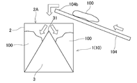
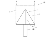
- FIG. 1 It is the top view (a) and front view (b) which show the solid substance accommodation hopper guide apparatus provided with this solid substance accommodation hopper guide apparatus which concerns on Embodiment 1 of this invention, and this solid substance accommodation hopper guide apparatus. It is a figure which shows the dust removal equipment periphery of the power plant to which the guide apparatus for solid substance accommodation hoppers of FIG. 1 is applied. It is a conceptual diagram which shows the use condition which the guide body of the guide apparatus for solid substance accommodation hoppers of FIG. 1 expand
- FIG. 6 is a front view showing a state in which the guide body of the solid material containing hopper guide device of FIG.
- FIG. 1 shows a solid material containing hopper guide device 1 according to this embodiment and a solid material containing hopper provided with the solid material containing hopper guide device 1. It is the top view (a) which shows the installation 10, and the front view (b).
- This solid material containing hopper guide device 1 is a device for properly containing and collecting solid matter in the hopper 2, and mainly includes a guide body 3, an air compressor (drive mechanism) 4, and a distance sensor (detection). Part) 5.
- the solid material is the garbage 100 such as garbage or driftwood. That is, as shown in FIG. 2, a water intake screen 102 is installed at the water intake 101 of the power plant, and a dust remover 103 is installed above the water intake screen 102. Further, the conveyor 104 is installed such that the base end portion 104 a of the conveyor 104 is adjacent to the dust remover 103, the tip end portion 104 b side is directed upward, and the hopper 2 is installed below the tip end portion 104 b of the conveyor 104. The hopper 2 is installed above the ground by the support pillar 20.
- the dust 100 staying on the water intake screen 102 is removed (raised) by the dust remover 103, and the removed dust 100 is placed on the conveyor 104.
- the garbage 100 is conveyed to the hopper 2 by the conveyor 104 and is dropped and accommodated in the hopper 2. Thereafter, when a certain amount of the dust 100 in the hopper 2 is accumulated, for example, it is separated into general waste such as driftwood and industrial waste such as bottles and cans, and is carried out by a truck each time.
- the hopper 2 is a cup-like shape having an upper opening 2A, and is a storage box in which the dust 100 conveyed by the conveyor 104 falls and is stored from the upper opening 2A.
- the hopper 2 has a substantially square cubic shape in this embodiment, and has an open / close door (not shown) for taking out the dust 100 on one side surface (side wall) 21.
- the bottom is flat (planar).
- the hopper 2 is arrange
- the guide body 3 is disposed at the bottom of the hopper 2 and can be expanded, contracted, and contracted.
- the guide body 3 When the guide body 3 is expanded, the guide body 3 has a substantially mountain shape, and guides the dust 100 dropped from the conveyor 104 to the side surface 21 of the hopper 2 and contracts. It becomes a flat state substantially along the bottom of the hopper 2.
- the air compressor 4 is a drive unit that expands and contracts the guide body 3.
- the guide body 3 is made of an elastic material (for example, a hard rubber material) that can be extended and contracted and has a desired strength, is in a bag shape or a balloon shape, and the bottom surface is fixed along the entire bottom surface of the hopper 2. ing. In this embodiment, it is shaped in advance so as to be in a substantially quadrangular pyramid shape when inflated and flattened when shrunk. The guide body 3 expands and contracts due to the inflow and outflow of compressed air.
- an elastic material for example, a hard rubber material
- the air compressor 4 is an air source (fluid source) that generates compressed air (fluid) and supplies the compressed air (fluid) to the guide body 3.
- the air compressor 4 is disposed outside the hopper 2 and is connected to the guide body 3 via an air pipe 41. It is connected. Then, when compressed air is supplied / inflowed from the air compressor 4 to the guide body 3, the guide body 3 swells into a substantially quadrangular pyramid shape (substantially mountain shape) as shown by reference numeral 3A in FIG. When the compressed air completely escapes (flows out) from the guide body 3, the guide body 3 contracts and becomes almost flat along the bottom of the hopper 2 as indicated by reference numeral 3C in FIG.
- the strength of the guide body 3 is set so as not to be damaged or deformed even when the dust 100 is accumulated.
- the drive mechanism may be configured by a hydraulic pressure source instead of the air compressor 4 according to the weight of the accumulated dust 100, and the pressure oil may be supplied into the guide body 3 instead of the compressed air.
- the bottom surface of the guide body 3 is fixed to the bottom portion of the hopper 2, the bottom portion of the hopper 2 may also serve as the bottom surface of the guide body 3 without having the bottom surface / bottom portion in the guide body 3 itself.
- Such a guide body 3 is formed and arranged so that the top portion 31 of the guide body 3 is located almost directly below the dust 100 falling from the conveyor 104 in the unfolded state. That is, in this embodiment, as described above, the dust 100 falls on the substantially central portion on the plane of the hopper 2, so that the substantially central portion on the plane of the guide body 3 as shown in FIG. Are formed and arranged so that the top portion 31 is located at the top.
- the top portion 31 is located at the dropping position, and the guide body 3 is formed and arranged in an uneven (tilted) mountain shape.
- the guide body 3 can be developed into a plurality of substantially mountain shapes having different inclination angles (vertical angles). That is, by changing the inflow amount (air pressure) of the compressed air supplied from the air compressor 4, the height of the quadrangular pyramid in which the guide body 3 swells changes, and it develops into a plurality of quadrangular pyramids with different inclination angles. ing.
- the two quadrangular pyramids 3A can be developed into two quadrangular pyramids 3A and a second quadrangular pyramid 3B that is approximately half the height of the first quadrangular pyramid 3A.
- the first quadrangular pyramid 3A and the second quadrangular pyramid 3B guide the dust 100 dropped from the conveyor 104 to the side surface 21 of the hopper 2 and then shrink in the hopper 2 when the dust 100 accumulates.
- the height and the inclination angle are set so that the dust 100 is deposited on the average.
- the distance sensor 5 is a sensor that is disposed in the hopper 2 and detects the accommodation state of the dust 100 in the hopper 2. That is, a sensor that detects the distance to the object, for example, by applying ultrasonic waves or light (infrared, laser, etc.) to the object and calculating the distance to the object based on the reflected ultrasonic waves or light, Disposed at the four corners of the opening edge of the upper opening 2A of the hopper 2, respectively.
- ultrasonic waves or light infrared, laser, etc.
- the air compressor 4 expands and contracts the guide body 3 based on the detection result of the distance sensor 5. That is, a control unit (not shown) for controlling the air compressor 4 and each distance sensor 5 are connected to be able to communicate with each other, and a detection result (distance to the dust 100) from each distance sensor 5 is sequentially transmitted to the control unit. The Then, when the dust 100 accumulates to a predetermined height in the hopper 2 in a state where the guide body 3 is deployed (when the distance from the distance sensor 5 to the dust 100 reaches a predetermined value), the control unit turns the air compressor 4 on. By controlling, the compressed air in the guide body 3 is extracted and the guide body 3 is expanded and contracted. At this time, the guide body 3 is unfolded and contracted at the latest before the tip 104b of the conveyor 104 contacts the dust 100 in the hopper 2.
- the guide body 3 may be arbitrarily expanded and contracted according to the accommodation state of the dust 100 in the hopper 2 as a detection result of each distance sensor 5. For example, when the dust 100 accumulates in the hopper 2 to the first height in the state of the first quadrangular pyramid 3A, the guide body 3 is contracted and expanded into the second quadrangular pyramid 3B, and then in the hopper 2 When the dust 100 is deposited to the second height, the guide body 3 is completely contracted to be in a flat state 3C. Furthermore, the guide body 3 may be expanded small again after being expanded depending on the accommodation state of the dust 100 or the like.
- the accommodation state of the dust 100 in the hopper 2 is detected and monitored by the distance sensor 5, and when the dust 100 accumulates to a predetermined height in the hopper 2, the air compressor 4 is driven and controlled to compress the guide body 3. Air is blown out.
- the guide body 3 is completely contracted to be in a flat state 3 ⁇ / b> C substantially along the bottom of the hopper 2.
- a part of the dust 100 accumulated on the side surface 21 side of the hopper 2 flows to a portion (almost central portion on the plane of the hopper 2) located at the top portion 31 of the guide body 3 as shown in the figure.
- the portion is depressed and the dust 100 is deposited. That is, the dust 100 flows and accumulates so that the portion (center portion) where the dust 100 falls is low and the periphery (side 21 side) is high.
- the dust 100 falls from the conveyor 104, as shown in the figure, the dust 100 accumulates in the recessed portion, and the dust 100 accumulates in the hopper 2 on average (almost flat with no height deviation). Is done.
- the dust 100 is averagely deposited in the hopper 2 by expanding or contracting the guide body 3. Therefore, the conveyor 104 can be prevented from contacting the accumulated dust 100, and the capacity of the hopper 2 can be used effectively. Further, it is not necessary to monitor the accumulation state of the dust 100 in the hopper 2 or to flatten the piled dust 100 by human power, so that the working time and labor of the worker can be significantly reduced. As a result, not only the safety and health of the worker are improved, but the worker can concentrate on dam discharge. Moreover, since it is reduced that the conveyor 104 comes into contact with the garbage 100 and the conveyor 104 breaks down and stops operation, it is possible to maintain power generation satisfactorily by continuously and stably generating power.
- the top 31 is located almost directly below the dust 100 falling from the conveyor 104, so that the dust 100 falling from the conveyor 104 is guided to the entire side surface 21 side of the hopper on average.
- the dust 100 is deposited on the outer periphery 21 side in the hopper 2 on average. As a result, the dust 100 can be deposited on the hopper 2 on the average.
- the trash 100 can be removed from the hopper by changing the inclination angle and height of the guide body 3 according to the type and accumulation state of the dust 100. It becomes possible to deposit on an average within 2.
- the guide body 3 is automatically expanded and contracted by the air compressor 4 based on the accommodation state (deposition state) of the dust 100 detected by the distance sensor 5, the operator looks at the accommodation state of the dust 100. There is no need to expand and contract the guide body 3. As a result, the working time and labor of the worker can be reduced, and the guide body 3 can be expanded and contracted at an appropriate timing, and the dust 100 can be deposited in the hopper 2 on the average.
- the compressed air is supplied to the guide body 3 from the drive mechanism constituted by the air compressor 4 and the guide body 3 expands and contracts only by flowing the compressed air into and out of the guide body 3.
- the expansion and contraction can be controlled appropriately, quickly and easily.
- the drive mechanism since the drive mechanism only needs to be configured by the air compressor 4 to allow the fluid to flow into and out of the guide body 3, the configuration can be simplified and the facility cost and maintenance cost can be reduced.
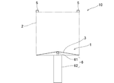
- FIG. 5 shows a solid material containing hopper guide device 1 according to this embodiment and a solid material containing hopper provided with the solid material containing hopper guide device 1.
- 2 is a front view showing the facility 10.
- the hydraulic cylinder 6 includes a plunger (piston) 61 and a cylinder body 62, and the cylinder body 62 is disposed outside the bottom of the hopper 2 (the lower surface of the hopper 2).
- the plunger 61 reciprocates along the axial direction of the cylinder body 62, passes through the bottom portion of the hopper 2 (the bottom surface of the guide body 3), and reciprocates up and down from a substantially central portion on the plane of the hopper 2. It is installed.
- An extendable guide body 3 is provided so as to cover such a plunger 61.
- the plunger 61 moves up and down, and the guide body 3 expands and contracts accordingly.
- a hydraulic pressure source not shown
- the guide body 3 expands in a quadrangular pyramid shape
- the guide body 3 becomes hopper as shown in FIG. 2 flattened almost along the bottom.
- the height and inclination angle of the quadrangular pyramid-shaped guide body 3 can be arbitrarily changed by arbitrarily changing the protruding length of the plunger 61 from the cylinder body 62.
- a fluid compressed air or pressurized oil
- the guide body 3 may be pushed up by the plunger 61 and a fluid may be supplied into the guide body 3 to expand the guide body 3 into a quadrangular pyramid shape.
- the conveyor 104 can be prevented from coming into contact with the accumulated dust 100, and the capacity of the hopper 2 can be used effectively.
- the developed guide body 3 is supported by the plunger 61, the developed state of the guide body 3 can be maintained well, and as a result, the dust 100 can be guided appropriately.
- the guide body 3 expands in a quadrangular pyramid shape, but depending on the shape of the hopper 2 and the size and properties of the solid matter, a pyramid shape other than the quadrangular pyramid shape, a conical shape, etc. You may make it expand
- the detection part is comprised with the distance sensor 5, you may comprise with a camera, a proximity switch (what turns on or off when a solid substance is accommodated to a predetermined height), etc.
- the guide body 3 may be made of a plate material and may be a mechanism for mechanically expanding and contracting.
- the metal plate may be expanded in a pyramid shape, or may be folded and contracted into a flat shape.
- the drive mechanism is constituted by the hydraulic cylinder 6, but it is constituted by a rack (corresponding to the plunger 61) and a pinion (corresponding to the cylinder body 62), or the plunger 61 is constituted by a plurality of tubes. And may be contracted.
- the air compressor 4 is automatically controlled to expand and contract the guide body 3 based on the accommodation state of the dust 100 in the hopper 2 detected by the distance sensor 5.
- the guide body 3 may be manually expanded and contracted at the operator's discretion.
- the present invention can be applied to other solid matters such as quarry debris and concrete.
Landscapes
- Engineering & Computer Science (AREA)
- Mechanical Engineering (AREA)
- Filling Or Emptying Of Bunkers, Hoppers, And Tanks (AREA)
- Auxiliary Methods And Devices For Loading And Unloading (AREA)
Abstract
ホッパー内に堆積した塵芥にコンベアが接触するのを防止して、かつ、ホッパーの容量を有効に利用可能にする。上部開口(2A)を有するカップ状でコンベア(104)で搬送された塵芥(100)が上部開口(2A)から落下して収容されるホッパー(2)の底部に配設され、展開収縮が自在なガイド体(3)と、ガイド体(3)を展開収縮させるエアコンプレッサ(4)と、を備え、ガイド体(3)は、展開すると略山形状となり、コンベア(104)から落下した塵芥(100)をホッパー(2)の側面(21)側に案内し、収縮するとホッパー(2)の底部にほぼ沿った平坦な状態となる。
Description
この発明は、塵芥などの固形物をホッパー内に収容、収集するための固形物収容ホッパー用ガイド装置および、このガイド装置を備えた固形物収容ホッパー設備に関する。
例えば、発電所の取水口には、発電機の出力が低下するのを防止するために、取水スクリーンが設置され、ゴミや流木などの塵芥が発電取水に混入しないようにしている。そして、取水スクリーンに滞留した塵芥を除塵機によって取り除き(掻き揚げ)、取り除いた塵芥はコンベアでホッパー(収容ボックス)に運ばれて、ホッパー内に落下、収容される(例えば、特許文献1参照。)。その後、ホッパー内の塵芥が一定量溜まると、分別して都度搬出している。
ところで、コンベアで運ばれた塵芥は、ホッパーの開口上部から落下されて収容されるため、ホッパー内に山積み(山なり)の状態となり、中央部(コンベアからの落下箇所の真下)が高くなる。このため、コンベアの先端部が塵芥に接触してコンベアが故障、運転停止するおそれがある。そして、コンベアが故障すると、除塵機で取り除いた塵芥を移動、搬送できなくなり、除塵機での除塵が行えなくなって、結果的に発電取水ができなくなる。このため、塵芥の堆積状況を常に目視確認する必要があった。
さらに、コンベアが塵芥に接触するのを防止したり、ホッパーの収容体積・容量を最大限利用したりするために、山積みになった塵芥を人力で熊手などを使用して平坦にする必要があった。殊に出水時には、上流河川からの塵芥の流入量が増加するため、ホッパー内の監視や平坦化作業などを頻繁に行う必要があった。このため、多大な時間と労力を要するばかりでなく、休日や夜間に作業員を確保することが困難であり、また、作業員の安全面や健康面での考慮・ケアが必要であった。
そこでこの発明は、ホッパー内に堆積した固形物にコンベアが接触するのを防止して、かつ、ホッパーの容量を有効に利用可能にする、固形物収容ホッパー用ガイド装置および固形物収容ホッパー設備を提供することを目的とする。
上記課題を解決するために、請求項1に記載の発明は、上部開口を有するカップ状でコンベアで搬送された固形物が前記上部開口から落下して収容されるホッパーの底部に配設され、展開収縮が自在なガイド体と、前記ガイド体を展開収縮させる駆動機構と、を備え、前記ガイド体は、展開すると略山形状となり、前記コンベアから落下した固形物を前記ホッパーの側面側に案内し、収縮すると前記ホッパーの底部にほぼ沿った平坦な状態となる、ことを特徴とする固形物収容ホッパー用ガイド装置である。
この発明によれば、ガイド体が展開した状態では、コンベアから落下した固形物がホッパーの側面側に案内され、ホッパーの側面側(外周側)に固形物が堆積する。次に、ガイド体が収縮してホッパーの底部にほぼ沿った平坦な状態となると、ホッパーの側面側に堆積していた固形物の一部がガイド体の頂部に位置する部分に流れて、その部分が窪んで固形物が堆積した状態となる。続いて、コンベアから固形物が落下すると、窪んだ部分に固形物が堆積して、ホッパー内に固形物が平均的に(高さの偏りがなくほぼ平坦に)堆積される。
請求項2に記載の発明は、請求項1に記載の固形物収容ホッパー用ガイド装置において、前記ガイド体は、展開した状態で頂部が、前記コンベアから落下する固形物のほぼ真下に位置する、ことを特徴とする。
請求項3に記載の発明は、請求項1または2に記載の固形物収容ホッパー用ガイド装置において、前記ガイド体は、傾斜角が異なる複数の略山形状に展開可能となっている、ことを特徴とする。
請求項4に記載の発明は、請求項1から3に記載の固形物収容ホッパー用ガイド装置において、前記ホッパーに配設され、前記ホッパー内の前記固形物の収容状態を検知する検知部を備え、前記駆動機構は、前記検知部の検出結果に基づいて前記ガイド体を展開収縮させる、ことを特徴とする。
請求項5に記載の発明は、請求項1から4に記載の固形物収容ホッパー用ガイド装置において、前記ガイド体は、流体の流入流出によって展開収縮が自在で、前記駆動機構は、前記ガイド体に流体を供給する流体源で構成されている、ことを特徴とする。
請求項6に記載の発明は、上部開口を有するカップ状でコンベアで搬送された固形物が前記上部開口から落下して収容されるホッパーを有する固形物収容ホッパー設備であって、請求項1から5のいずれか1項に記載の固形物収容ホッパー用ガイド装置を備えたことを特徴とする。
請求項1、6の発明によれば、ガイド体を展開させたり収縮させたりすることで、ホッパー内に固形物が平均的に堆積されるため、堆積した固形物にコンベアが接触するのを防止することができ、かつ、ホッパーの容量を有効に利用することができる。また、ホッパー内の固形物の堆積状況を監視したり、山積みになった固形物を人力で平坦化したりする必要がなく、作業員の作業時間と労力を著しく軽減することができる。
請求項2の発明によれば、ガイド体が展開した状態で、その頂部がコンベアから落下する固形物のほぼ真下に位置するため、コンベアから落下した固形物がホッパーの全側面側に平均的に案内され、固形物がホッパー内の外周側に平均的に堆積する。この結果、固形物をホッパー内により平均的に堆積させることが可能となる。
請求項3の発明によれば、傾斜角が異なる複数の略山形状にガイド体が展開可能なため、固形物の種類や堆積状態などに応じてガイド体の傾斜角を変えることで、固形物をホッパー内により平均的に堆積させることが可能となる。
請求項4の発明によれば、検知部で検出された固形物の収容状態(堆積状態)に基づいて、駆動機構によってガイド体が自動的に展開収縮されるため、作業員が固形物の収容状態を見てガイド体を展開収縮させる必要がない。この結果、作業員の作業時間と労力を軽減することができるとともに、適正なタイミングでガイド体を展開収縮させて、固形物をホッパー内により平均的に堆積させることが可能となる。
請求項5の発明によれば、流体源で構成された駆動機構からガイド体に流体を供給して、ガイド体に対して流体を流入流出させるだけでガイド体が展開収縮するため、ガイド体の展開収縮を適正かつ迅速、容易に制御することが可能となる。しかも、駆動機構を流体源で構成してガイド体に流体を流入流出させるだけでよいため、簡易に構成することができ、設備費や保守費を低減することが可能となる。
以下、この発明を図示の実施の形態に基づいて説明する。
(実施の形態1)
図1~図4は、この実施の形態を示し、図1は、この実施の形態に係る固形物収容ホッパー用ガイド装置1および、この固形物収容ホッパー用ガイド装置1を備えた固形物収容ホッパー設備10を示す平面図(a)と正面図(b)である。この固形物収容ホッパー用ガイド装置1は、固形物をホッパー2内に適正に収容、収集するための装置であり、主として、ガイド体3と、エアコンプレッサ(駆動機構)4と、距離センサ(検知部)5と、を備えている。
図1~図4は、この実施の形態を示し、図1は、この実施の形態に係る固形物収容ホッパー用ガイド装置1および、この固形物収容ホッパー用ガイド装置1を備えた固形物収容ホッパー設備10を示す平面図(a)と正面図(b)である。この固形物収容ホッパー用ガイド装置1は、固形物をホッパー2内に適正に収容、収集するための装置であり、主として、ガイド体3と、エアコンプレッサ(駆動機構)4と、距離センサ(検知部)5と、を備えている。
ここで、この実施の形態では、固形物がゴミや流木などの塵芥100の場合について、主として説明する。すなわち、図2に示すように、発電所の取水口101に取水スクリーン102が設置され、この取水スクリーン102の上方に除塵機103が設置されている。また、コンベア104の基端部104aが除塵機103に隣接し、先端部104b側が上方に向かうようにコンベア104が設置され、コンベア104の先端部104bの下方にホッパー2が設置されている。このホッパー2は、支持柱20によって地面よりも上方に設置されている。
そして、取水スクリーン102に滞留した塵芥100が除塵機103によって取り除けられ(掻き揚げられ)、取り除かれた塵芥100はコンベア104に載せられる。続いて、塵芥100は、コンベア104でホッパー2に運ばれて、ホッパー2内に落下、収容される。その後、ホッパー2内の塵芥100が一定量溜まると、例えば、流木などの一般廃棄物とビンや缶などの産業廃棄物とに分別して、トラックで都度搬出する。
ホッパー2は、上部開口2Aを有するカップ状で、コンベア104で搬送された塵芥100が上部開口2Aから落下して収容される収容ボックスである。このホッパー2は、図1に示すように、この実施の形態では、平面形状が略正方形の立方体状で、1つの側面(側壁)21に塵芥100を取り出すための開閉扉(図示せず)が設けられ、底部は平坦(平面)状になっている。また、ホッパー2は、平面上のほぼ中央部に塵芥100が落下するように配置されている。
ガイド体3は、ホッパー2の底部に配設され、展開・膨張および収縮が自在で、展開すると略山形状となり、コンベア104から落下した塵芥100をホッパー2の側面21側に案内し、収縮するとホッパー2の底部にほぼ沿った平坦な状態となる。また、エアコンプレッサ4は、ガイド体3を展開収縮させる駆動部である。
具体的には、ガイド体3は、伸縮自在で所望の強度を有する伸縮材(例えば、硬質ゴム材)で構成され、袋状・風船状で、底面がホッパー2の底部全面に沿って固定されている。そして、この実施の形態では、膨らんだ状態で略四角錐状となり、縮むと平坦になるように予め成型されている。また、このガイド体3は、圧縮空気の流入流出によって展開したり収縮したりする。
一方、エアコンプレッサ4は、圧縮空気(流体)を生成してガイド体3に供給するエア源(流体源)であり、ホッパー2の外側に配設され、空気配管41を介してガイド体3と接続されている。そして、エアコンプレッサ4からガイド体3に圧縮空気が供給・流入されると、図1(b)の符号3Aに示すように、ガイド体3が膨らんで略四角錐状(略山形状)となり、ガイド体3から圧縮空気が完全に抜けると(流出すると)、図1(b)の符号3Cに示すように、ガイド体3が縮んでホッパー2の底部にほぼ沿って平坦になる。
ここで、ガイド体3の強度は、塵芥100が堆積しても破損したり変形したりしないように設定されている。また、堆積する塵芥100の重量などに応じて、エアコンプレッサ4に代えて油圧源で駆動機構を構成し、圧縮空気に代って圧油をガイド体3内に供給してもよい。さらに、ガイド体3の底面がホッパー2の底部に固定されているが、ガイド体3自体に底面・底部を有さずに、ホッパー2の底部がガイド体3の底面を兼ねてもよい。
このようなガイド体3は、展開した状態でその頂部31が、コンベア104から落下する塵芥100のほぼ真下に位置するように、形成、配置されている。すなわち、この実施の形態では、上記のように、ホッパー2の平面上のほぼ中央部に塵芥100が落下するため、図1(a)に示すように、ガイド体3の平面上のほぼ中央部に頂部31が位置するように、形成、配置されている。
一方、ホッパー2の平面上のほぼ中央部に塵芥100が落下しない場合には、その落下位置に頂部31が位置し、偏った(傾いた)山形状にガイド体3が形成、配置される。
また、ガイド体3は、傾斜角(頂角)が異なる複数の略山形状に展開可能となっている。すなわち、エアコンプレッサ4から供給する圧縮空気の流入量(空気圧)を変えることで、ガイド体3が膨らんだ四角錐の高さが変わり、傾斜角が異なる複数の四角錐状に展開するようになっている。
ここで、圧縮空気の流入量を任意に変えることで四角錐の高さ、傾斜角が任意に変化するが、この実施の形態では、図1(b)に示すように、最大・最高の第1の四角錐3Aと、第1の四角錐3Aの略半分の高さの第2の四角錐3Bとの2つの略山形状に展開可能とする。この第1の四角錐3Aと第2の四角錐3Bは、コンベア104から落下した塵芥100をホッパー2の側面21側に案内し、かつ、その後縮んで塵芥100が堆積した際に、ホッパー2内に塵芥100が平均的に堆積するように、高さ、傾斜角が設定されている。
距離センサ5は、ホッパー2に配設され、ホッパー2内の塵芥100の収容状態を検知するセンサである。すなわち、物体との距離を検知するセンサであり、例えば、物体に超音波や光(赤外線、レーザ等)を当てて、反射した超音波や光に基づいて物体までの距離を算出するもので、ホッパー2の上部開口2Aの開口端縁の四隅にそれぞれ配設されている。このような各距離センサ5で、ホッパー2内に収容された塵芥100までの距離を算出することで、ホッパー2内のどこにどのくらい塵芥100が収容されたかを検知できるようになっている。
そして、エアコンプレッサ4は、距離センサ5の検出結果に基づいてガイド体3を展開収縮させる。すなわち、エアコンプレッサ4を制御する制御部(図示せず)と各距離センサ5とが通信自在に接続され、各距離センサ5からの検知結果(塵芥100までの距離)が逐次制御部に送信される。そして、ガイド体3が展開した状態で、ホッパー2内に塵芥100が所定の高さまで堆積すると(距離センサ5から塵芥100までの距離が所定値に達すると)、制御部は、エアコンプレッサ4を制御してガイド体3内の圧縮空気を抜いてガイド体3を展開収縮させる。この際、遅くともコンベア104の先端部104bがホッパー2内の塵芥100に接触する前に、ガイド体3を展開収縮させる。
また、各距離センサ5の検出結果であるホッパー2内の塵芥100の収容状態などに応じて、ガイド体3を任意に展開収縮させてもよい。例えば、第1の四角錐3Aの状態で、ホッパー2内に塵芥100が第1の高さまで堆積すると、ガイド体3を収縮させて第2の四角錐3Bに展開し、その後、ホッパー2内に塵芥100が第2の高さまで堆積すると、ガイド体3を完全に収縮させて平坦な状態3Cにする。さらに、塵芥100の収容状態などに応じて、ガイド体3を小さく展開させた後に再度大きく展開してもよい。
次に、このような構成の固形物収容ホッパー用ガイド装置1および固形物収容ホッパー設備10の動作・作用などについて説明する。
まず、ホッパー2に塵芥100が収容されていない状態で、エアコンプレッサ4からガイド体3に圧縮空気を供給して、ガイド体3を第1の四角錐3Aに展開する。この状態でコンベア104から塵芥100が搬送されると、図3に示すように、コンベア104の先端部104bから落下した塵芥100は、ガイド体3によってホッパー2の側面21側に案内され、ホッパー2の側面21側(外周側)に塵芥100が堆積していく。
次に、距離センサ5によってホッパー2内の塵芥100の収容状態が検知、監視され、ホッパー2内に塵芥100が所定の高さまで堆積すると、エアコンプレッサ4が駆動制御されてガイド体3内の圧縮空気が抜かれる。例えば、図4に示すように、ガイド体3が完全に収縮してホッパー2の底部にほぼ沿った平坦な状態3Cになる。
これにより、ホッパー2の側面21側に堆積していた塵芥100の一部が、図示のように、ガイド体3の頂部31に位置する部分(ホッパー2の平面上のほぼ中央部)に流れて、その部分が窪んで塵芥100が堆積した状態となる。すなわち、塵芥100が落下する部分(中央部)が低くその周り(側面21側)が高くなるように、塵芥100が流動して堆積する。
続いて、コンベア104から塵芥100が落下すると、図示のように、窪んだ部分に塵芥100が堆積して、ホッパー2内に塵芥100が平均的に(高さの偏りがなくほぼ平坦に)堆積される。
以上のように、この固形物収容ホッパー用ガイド装置1および固形物収容ホッパー設備10によれば、ガイド体3を展開させたり収縮させたりすることで、ホッパー2内に塵芥100が平均的に堆積されるため、堆積した塵芥100にコンベア104が接触するのを防止することができ、かつ、ホッパー2の容量を有効に利用することができる。また、ホッパー2内の塵芥100の堆積状況を監視したり、山積みになった塵芥100を人力で平坦化したりする必要がなく、作業員の作業時間と労力を著しく軽減することができる。この結果、作業員の安全性、健康面が向上するばかりでなく、作業員は、ダム放流等に専念することができる。しかも、コンベア104が塵芥100に接触してコンベア104が故障、運転停止することが軽減されるため、発電取水を継続的・安定的に行って発電を良好に維持することが可能となる。
また、ガイド体3が展開した状態で、その頂部31がコンベア104から落下する塵芥100のほぼ真下に位置するため、コンベア104から落下した塵芥100がホッパーの全側面21側に平均的に案内され、塵芥100がホッパー2内の外周21側に平均的に堆積する。この結果、塵芥100をホッパー2内により平均的に堆積させることが可能となる。
さらに、傾斜角が異なる複数の略山形状にガイド体3が展開可能なため、塵芥100の種類や堆積状態などに応じてガイド体3の傾斜角や高さを変えることで、塵芥100をホッパー2内により平均的に堆積させることが可能となる。
一方、距離センサ5で検出された塵芥100の収容状態(堆積状態)に基づいて、エアコンプレッサ4によってガイド体3が自動的に展開収縮されるため、作業員が塵芥100の収容状態を見てガイド体3を展開収縮させる必要がない。この結果、作業員の作業時間と労力を軽減することができるとともに、適正なタイミングでガイド体3を展開収縮させて、塵芥100をホッパー2内により平均的に堆積させることが可能となる。
また、エアコンプレッサ4で構成された駆動機構からガイド体3に圧縮空気を供給して、ガイド体3に対して圧縮空気を流入流出させるだけでガイド体3が展開収縮するため、ガイド体3の展開収縮を適正かつ迅速、容易に制御することが可能となる。しかも、駆動機構をエアコンプレッサ4で構成してガイド体3に流体を流入流出させるだけでよいため、簡易に構成することができ、設備費や保守費を低減することが可能となる。
(実施の形態2)
図5、図6は、この実施の形態を示し、図5は、この実施の形態に係る固形物収容ホッパー用ガイド装置1および、この固形物収容ホッパー用ガイド装置1を備えた固形物収容ホッパー設備10を示す正面図である。この実施の形態では、駆動機構がエアコンプレッサ4に代って油圧シリンダ6で構成されている点で、実施の形態1と構成が異なり、実施の形態1と同等の構成については、同一符号を付することでその説明を省略する。
図5、図6は、この実施の形態を示し、図5は、この実施の形態に係る固形物収容ホッパー用ガイド装置1および、この固形物収容ホッパー用ガイド装置1を備えた固形物収容ホッパー設備10を示す正面図である。この実施の形態では、駆動機構がエアコンプレッサ4に代って油圧シリンダ6で構成されている点で、実施の形態1と構成が異なり、実施の形態1と同等の構成については、同一符号を付することでその説明を省略する。
油圧シリンダ6は、プランジャ(ピストン)61とシリンダ本体62とを備え、シリンダ本体62は、ホッパー2の底部の外側(ホッパー2の下面)に配設されている。プランジャ61は、シリンダ本体62の軸方向に沿って往復動し、ホッパー2の底部(ガイド体3の底面)を貫通し、ホッパー2の平面上のほぼ中央部から上下に往復動するように配設されている。このようなプランジャ61を覆うように伸縮自在なガイド体3が配設されている。
そして、油圧源(図示せず)からシリンダ本体62に油圧を供給することで、プランジャ61が上下動し、これに伴ってガイド体3が展開収縮する。例えば、プランジャ61が上方に延びると、図5に示すように、ガイド体3が四角錐状に展開し、プランジャ61が下方に完全に縮むと、図6に示すように、ガイド体3がホッパー2の底部にほぼ沿って平坦になる。この際、シリンダ本体62からのプランジャ61の突出長さを任意に変えることで、四角錐状のガイド体3の高さ、傾斜角を任意に変えることができる。
ここで、塵芥100(固形物)の性状や重量などに応じて、必要な強度、剛性などが得られるように、実施の形態1と同様に、ガイド体3内に流体(圧縮空気や圧油)を満たしてもよい。すなわち、プランジャ61でガイド体3を押し上げるとともに、ガイド体3内に流体を供給して、ガイド体3を四角錐状に展開してもよい。
このような実施の形態によれば、実施の形態1と同様に、堆積した塵芥100にコンベア104が接触するのを防止することができ、かつ、ホッパー2の容量を有効に利用することができる。また、展開したガイド体3がプランジャ61で支持されるため、ガイド体3の展開状態を良好に維持することができ、その結果、塵芥100を適正に案内することができる。
以上、この発明の実施の形態について説明したが、具体的な構成は、上記の実施の形態に限られるものではなく、この発明の要旨を逸脱しない範囲の設計の変更等があっても、この発明に含まれる。例えば、上記の実施の形態では、ガイド体3が四角錐状に展開するが、ホッパー2の形状や固形物の大きさ、性状などに応じて、四角錐状以外の角錐状や円錐状など、その他の形状に展開するようにしてもよい。また、検知部を距離センサ5で構成しているが、カメラや近接スイッチ(所定の高さまで固形物が収容されるとスイッチがオンまたはオフするもの)などで構成してもよい。
さらに、ガイド体3を板材で構成して、機械的に展開収縮する機構にしてもよい。例えば、金属板が角錐状に展開したり、折り重なって平坦状に収縮したりするようにしてもよい。
また、実施の形態2において駆動機構を油圧シリンダ6で構成しているが、ラック(プランジャ61に相当)とピニオン(シリンダ本体62に相当)で構成したり、プランジャ61を複数の管体で構成して収縮するようにしたりしてもよい。
ところで、上記の実施の形態では、距離センサ5で検知されたホッパー2内の塵芥100の収容状態に基づいて、自動的にエアコンプレッサ4を制御してガイド体3を展開収縮しているが、作業員の判断でガイド体3を手動で展開収縮してもよい。また、固形物が取水スクリーン102に滞留した塵芥100の場合について説明したが、その他の固形物、例えば、採石場の土石やコンクリートにも適用できることは勿論である。
1 固形物収容ホッパー用ガイド装置
10 固形物収容ホッパー設備
2 ホッパー
2A 上部開口
21 側面(側壁)
3 ガイド体
31 頂部
4 エアコンプレッサ(駆動機構)
5 距離センサ(検知部)
6 油圧シリンダ(駆動機構)
100 塵芥
104 コンベア
10 固形物収容ホッパー設備
2 ホッパー
2A 上部開口
21 側面(側壁)
3 ガイド体
31 頂部
4 エアコンプレッサ(駆動機構)
5 距離センサ(検知部)
6 油圧シリンダ(駆動機構)
100 塵芥
104 コンベア
Claims (6)
- 上部開口を有するカップ状でコンベアで搬送された固形物が前記上部開口から落下して収容されるホッパーの底部に配設され、展開収縮が自在なガイド体と、
前記ガイド体を展開収縮させる駆動機構と、を備え、
前記ガイド体は、展開すると略山形状となり、前記コンベアから落下した固形物を前記ホッパーの側面側に案内し、収縮すると前記ホッパーの底部にほぼ沿った平坦な状態となる、
ことを特徴とする固形物収容ホッパー用ガイド装置。 - 前記ガイド体は、展開した状態で頂部が、前記コンベアから落下する固形物のほぼ真下に位置する、
ことを特徴とする請求項1に記載の固形物収容ホッパー用ガイド装置。 - 前記ガイド体は、傾斜角が異なる複数の略山形状に展開可能となっている、
ことを特徴とする請求項1または2のいずれか1項に記載の固形物収容ホッパー用ガイド装置。 - 前記ホッパーに配設され、前記ホッパー内の前記固形物の収容状態を検知する検知部を備え、
前記駆動機構は、前記検知部の検出結果に基づいて前記ガイド体を展開収縮させる、
ことを特徴とする請求項1から3のいずれか1項に記載の固形物収容ホッパー用ガイド装置。 - 前記ガイド体は、流体の流入流出によって展開収縮が自在で、
前記駆動機構は、前記ガイド体に流体を供給する流体源で構成されている、
ことを特徴とする請求項1から4のいずれか1項に記載の固形物収容ホッパー用ガイド装置。 - 上部開口を有するカップ状でコンベアで搬送された固形物が前記上部開口から落下して収容されるホッパーを有する固形物収容ホッパー設備であって、
請求項1から5のいずれか1項に記載の固形物収容ホッパー用ガイド装置を備えたことを特徴とする固形物収容ホッパー設備。
Priority Applications (2)
| Application Number | Priority Date | Filing Date | Title |
|---|---|---|---|
| JP2016540093A JP6065166B1 (ja) | 2016-01-04 | 2016-01-04 | 固形物収容ホッパー用ガイド装置および固形物収容ホッパー設備 |
| PCT/JP2016/050031 WO2017119053A1 (ja) | 2016-01-04 | 2016-01-04 | 固形物収容ホッパー用ガイド装置および固形物収容ホッパー設備 |
Applications Claiming Priority (1)
| Application Number | Priority Date | Filing Date | Title |
|---|---|---|---|
| PCT/JP2016/050031 WO2017119053A1 (ja) | 2016-01-04 | 2016-01-04 | 固形物収容ホッパー用ガイド装置および固形物収容ホッパー設備 |
Publications (1)
| Publication Number | Publication Date |
|---|---|
| WO2017119053A1 true WO2017119053A1 (ja) | 2017-07-13 |
Family
ID=57890470
Family Applications (1)
| Application Number | Title | Priority Date | Filing Date |
|---|---|---|---|
| PCT/JP2016/050031 Ceased WO2017119053A1 (ja) | 2016-01-04 | 2016-01-04 | 固形物収容ホッパー用ガイド装置および固形物収容ホッパー設備 |
Country Status (2)
| Country | Link |
|---|---|
| JP (1) | JP6065166B1 (ja) |
| WO (1) | WO2017119053A1 (ja) |
Families Citing this family (1)
| Publication number | Priority date | Publication date | Assignee | Title |
|---|---|---|---|---|
| CN110271878B (zh) * | 2019-07-22 | 2024-02-09 | 江苏阆达机械有限公司 | 一种plc控制系统 |
Citations (4)
| Publication number | Priority date | Publication date | Assignee | Title |
|---|---|---|---|---|
| JPS5529470B2 (ja) * | 1974-11-27 | 1980-08-04 | ||
| JPS56113583A (en) * | 1980-02-13 | 1981-09-07 | Fuji Heavy Ind Ltd | Hopper |
| JPH0577087U (ja) * | 1992-03-30 | 1993-10-19 | 東海ゴム工業株式会社 | 粉体の架橋防止装置 |
| JPH10114429A (ja) * | 1996-10-14 | 1998-05-06 | Nitsuchitsu:Kk | 搬送物の居付き防止装置 |
Family Cites Families (1)
| Publication number | Priority date | Publication date | Assignee | Title |
|---|---|---|---|---|
| JPS5529470A (en) * | 1978-08-21 | 1980-03-01 | Sankyo Dengyo Kk | Bridge preventive hopper |
-
2016
- 2016-01-04 WO PCT/JP2016/050031 patent/WO2017119053A1/ja not_active Ceased
- 2016-01-04 JP JP2016540093A patent/JP6065166B1/ja not_active Expired - Fee Related
Patent Citations (4)
| Publication number | Priority date | Publication date | Assignee | Title |
|---|---|---|---|---|
| JPS5529470B2 (ja) * | 1974-11-27 | 1980-08-04 | ||
| JPS56113583A (en) * | 1980-02-13 | 1981-09-07 | Fuji Heavy Ind Ltd | Hopper |
| JPH0577087U (ja) * | 1992-03-30 | 1993-10-19 | 東海ゴム工業株式会社 | 粉体の架橋防止装置 |
| JPH10114429A (ja) * | 1996-10-14 | 1998-05-06 | Nitsuchitsu:Kk | 搬送物の居付き防止装置 |
Also Published As
| Publication number | Publication date |
|---|---|
| JP6065166B1 (ja) | 2017-01-25 |
| JPWO2017119053A1 (ja) | 2018-01-11 |
Similar Documents
| Publication | Publication Date | Title |
|---|---|---|
| US8376682B2 (en) | Obstruction clearance mode for silo with reciprocating frame | |
| NL1039541C2 (nl) | Huisvuilcontainer en inbouweenheid daarvoor. | |
| SE529443C2 (sv) | Behållare i form av burk och avtagbart lock som har ett kragparti och förfarande för applicering av locket | |
| JP6065166B1 (ja) | 固形物収容ホッパー用ガイド装置および固形物収容ホッパー設備 | |
| KR101382588B1 (ko) | 산업용 폐기물질 수거장치 | |
| US7275906B1 (en) | Waste/recyclables loading machine | |
| US20100158651A1 (en) | Silo with reciprocating frame having blanking plate | |
| KR102133570B1 (ko) | 하·폐수 슬러지의 비산 및 오염방지 장치 | |
| RO116070B1 (ro) | Dispozitiv reutilizabil pentru distribuirea unui material vascos | |
| EA023450B1 (ru) | Комплекс по переработке битумосодержащих отходов мягких кровельных материалов | |
| CN209889865U (zh) | 一种料斗接驳站 | |
| CN205855421U (zh) | 一种料箱自动翻转机 | |
| US811801A (en) | Oil-cup. | |
| JP4205411B2 (ja) | 煙突内筒壁面洗浄装置 | |
| KR102200191B1 (ko) | 이동형 비산먼지 제거장치 | |
| KR102092999B1 (ko) | 탱크실 일체형 산업생산제품 세척장치 | |
| CN205771224U (zh) | 一种地埋式垃圾压缩机的升降装置 | |
| KR20120074637A (ko) | 미분탄 제조설비에서의 슈트내 부착탄 제거장치 | |
| KR101817999B1 (ko) | 슬러지 탈수 장치 | |
| CN105923402A (zh) | 一种省煤杂物过滤系统 | |
| CN107934323A (zh) | 一种垃圾压缩站 | |
| CN205652687U (zh) | 一种智能垃圾分类箱 | |
| ES3033970T3 (en) | Method and apparatus for compacting waste and vehicle comprising said apparatus | |
| CN205652696U (zh) | 一种智能环保垃圾箱长条类非柔性垃圾投放装置 | |
| US20100158650A1 (en) | Silo with reciprocating frame having beveled inner surfaces |
Legal Events
| Date | Code | Title | Description |
|---|---|---|---|
| ENP | Entry into the national phase |
Ref document number: 2016540093 Country of ref document: JP Kind code of ref document: A |
|
| 121 | Ep: the epo has been informed by wipo that ep was designated in this application |
Ref document number: 16883558 Country of ref document: EP Kind code of ref document: A1 |
|
| NENP | Non-entry into the national phase |
Ref country code: DE |
|
| 122 | Ep: pct application non-entry in european phase |
Ref document number: 16883558 Country of ref document: EP Kind code of ref document: A1 |