WO2017115657A1 - Non-oriented electromagnetic steel sheet and method for producing non-oriented electromagnetic steel sheet - Google Patents
Non-oriented electromagnetic steel sheet and method for producing non-oriented electromagnetic steel sheet Download PDFInfo
- Publication number
- WO2017115657A1 WO2017115657A1 PCT/JP2016/087279 JP2016087279W WO2017115657A1 WO 2017115657 A1 WO2017115657 A1 WO 2017115657A1 JP 2016087279 W JP2016087279 W JP 2016087279W WO 2017115657 A1 WO2017115657 A1 WO 2017115657A1
- Authority
- WO
- WIPO (PCT)
- Prior art keywords
- less
- steel sheet
- oriented electrical
- electrical steel
- grain size
- Prior art date
Links
- 229910000831 Steel Inorganic materials 0.000 title claims abstract description 42
- 239000010959 steel Substances 0.000 title claims abstract description 42
- 238000004519 manufacturing process Methods 0.000 title claims description 13
- XEEYBQQBJWHFJM-UHFFFAOYSA-N Iron Chemical group [Fe] XEEYBQQBJWHFJM-UHFFFAOYSA-N 0.000 claims abstract description 143
- 239000013078 crystal Substances 0.000 claims abstract description 65
- 230000005284 excitation Effects 0.000 claims abstract description 57
- 239000000203 mixture Substances 0.000 claims abstract description 28
- 238000002791 soaking Methods 0.000 claims description 73
- 229910000565 Non-oriented electrical steel Inorganic materials 0.000 claims description 72
- 229910052742 iron Inorganic materials 0.000 claims description 69
- 238000000137 annealing Methods 0.000 claims description 52
- 238000000034 method Methods 0.000 claims description 36
- 238000005097 cold rolling Methods 0.000 claims description 26
- 238000010438 heat treatment Methods 0.000 claims description 25
- 229910052785 arsenic Inorganic materials 0.000 claims description 14
- 229910052745 lead Inorganic materials 0.000 claims description 13
- 238000012360 testing method Methods 0.000 claims description 13
- 238000005098 hot rolling Methods 0.000 claims description 12
- 230000004907 flux Effects 0.000 claims description 11
- 238000004804 winding Methods 0.000 claims description 9
- 239000012535 impurity Substances 0.000 claims description 6
- 230000000694 effects Effects 0.000 description 25
- 230000001965 increasing effect Effects 0.000 description 14
- 239000000463 material Substances 0.000 description 14
- 238000005096 rolling process Methods 0.000 description 13
- 229910052761 rare earth metal Inorganic materials 0.000 description 12
- 150000002910 rare earth metals Chemical class 0.000 description 12
- 229910052718 tin Inorganic materials 0.000 description 7
- 239000011248 coating agent Substances 0.000 description 6
- 238000000576 coating method Methods 0.000 description 6
- 238000009826 distribution Methods 0.000 description 6
- 238000005259 measurement Methods 0.000 description 6
- 239000002244 precipitate Substances 0.000 description 6
- 238000001816 cooling Methods 0.000 description 5
- 150000001875 compounds Chemical class 0.000 description 4
- 239000011162 core material Substances 0.000 description 4
- 238000005520 cutting process Methods 0.000 description 4
- 238000011156 evaluation Methods 0.000 description 4
- 229920006395 saturated elastomer Polymers 0.000 description 4
- 230000000052 comparative effect Effects 0.000 description 3
- 230000007423 decrease Effects 0.000 description 3
- 230000003247 decreasing effect Effects 0.000 description 3
- 238000005554 pickling Methods 0.000 description 3
- 238000001556 precipitation Methods 0.000 description 3
- 238000011282 treatment Methods 0.000 description 3
- 238000005266 casting Methods 0.000 description 2
- 230000002708 enhancing effect Effects 0.000 description 2
- 230000006698 induction Effects 0.000 description 2
- 238000011835 investigation Methods 0.000 description 2
- 229910052750 molybdenum Inorganic materials 0.000 description 2
- 238000012545 processing Methods 0.000 description 2
- 238000001953 recrystallisation Methods 0.000 description 2
- 229910052721 tungsten Inorganic materials 0.000 description 2
- 229910000976 Electrical steel Inorganic materials 0.000 description 1
- 230000002411 adverse Effects 0.000 description 1
- 230000032683 aging Effects 0.000 description 1
- 229910045601 alloy Inorganic materials 0.000 description 1
- 239000000956 alloy Substances 0.000 description 1
- 229910052782 aluminium Inorganic materials 0.000 description 1
- 230000015572 biosynthetic process Effects 0.000 description 1
- 239000010960 cold rolled steel Substances 0.000 description 1
- 238000009749 continuous casting Methods 0.000 description 1
- 238000007796 conventional method Methods 0.000 description 1
- 238000005336 cracking Methods 0.000 description 1
- 230000006866 deterioration Effects 0.000 description 1
- 238000011161 development Methods 0.000 description 1
- 230000018109 developmental process Effects 0.000 description 1
- 238000005265 energy consumption Methods 0.000 description 1
- 230000007613 environmental effect Effects 0.000 description 1
- 238000002474 experimental method Methods 0.000 description 1
- 230000002349 favourable effect Effects 0.000 description 1
- 239000004615 ingredient Substances 0.000 description 1
- 238000003475 lamination Methods 0.000 description 1
- 238000007726 management method Methods 0.000 description 1
- 230000003287 optical effect Effects 0.000 description 1
- 230000001376 precipitating effect Effects 0.000 description 1
- 239000000047 product Substances 0.000 description 1
- 230000001737 promoting effect Effects 0.000 description 1
- 230000005855 radiation Effects 0.000 description 1
- 239000002994 raw material Substances 0.000 description 1
- 238000011084 recovery Methods 0.000 description 1
- 238000007670 refining Methods 0.000 description 1
- 238000009628 steelmaking Methods 0.000 description 1
- 230000003746 surface roughness Effects 0.000 description 1
- 150000003568 thioethers Chemical class 0.000 description 1
Images


Classifications
-
- C—CHEMISTRY; METALLURGY
- C21—METALLURGY OF IRON
- C21D—MODIFYING THE PHYSICAL STRUCTURE OF FERROUS METALS; GENERAL DEVICES FOR HEAT TREATMENT OF FERROUS OR NON-FERROUS METALS OR ALLOYS; MAKING METAL MALLEABLE, e.g. BY DECARBURISATION OR TEMPERING
- C21D1/00—General methods or devices for heat treatment, e.g. annealing, hardening, quenching or tempering
- C21D1/74—Methods of treatment in inert gas, controlled atmosphere, vacuum or pulverulent material
- C21D1/76—Adjusting the composition of the atmosphere
-
- C—CHEMISTRY; METALLURGY
- C21—METALLURGY OF IRON
- C21D—MODIFYING THE PHYSICAL STRUCTURE OF FERROUS METALS; GENERAL DEVICES FOR HEAT TREATMENT OF FERROUS OR NON-FERROUS METALS OR ALLOYS; MAKING METAL MALLEABLE, e.g. BY DECARBURISATION OR TEMPERING
- C21D8/00—Modifying the physical properties by deformation combined with, or followed by, heat treatment
- C21D8/12—Modifying the physical properties by deformation combined with, or followed by, heat treatment during manufacturing of articles with special electromagnetic properties
- C21D8/1216—Modifying the physical properties by deformation combined with, or followed by, heat treatment during manufacturing of articles with special electromagnetic properties the working step(s) being of interest
- C21D8/1222—Hot rolling
-
- C—CHEMISTRY; METALLURGY
- C21—METALLURGY OF IRON
- C21D—MODIFYING THE PHYSICAL STRUCTURE OF FERROUS METALS; GENERAL DEVICES FOR HEAT TREATMENT OF FERROUS OR NON-FERROUS METALS OR ALLOYS; MAKING METAL MALLEABLE, e.g. BY DECARBURISATION OR TEMPERING
- C21D8/00—Modifying the physical properties by deformation combined with, or followed by, heat treatment
- C21D8/12—Modifying the physical properties by deformation combined with, or followed by, heat treatment during manufacturing of articles with special electromagnetic properties
- C21D8/1216—Modifying the physical properties by deformation combined with, or followed by, heat treatment during manufacturing of articles with special electromagnetic properties the working step(s) being of interest
- C21D8/1233—Cold rolling
-
- C—CHEMISTRY; METALLURGY
- C21—METALLURGY OF IRON
- C21D—MODIFYING THE PHYSICAL STRUCTURE OF FERROUS METALS; GENERAL DEVICES FOR HEAT TREATMENT OF FERROUS OR NON-FERROUS METALS OR ALLOYS; MAKING METAL MALLEABLE, e.g. BY DECARBURISATION OR TEMPERING
- C21D8/00—Modifying the physical properties by deformation combined with, or followed by, heat treatment
- C21D8/12—Modifying the physical properties by deformation combined with, or followed by, heat treatment during manufacturing of articles with special electromagnetic properties
- C21D8/1244—Modifying the physical properties by deformation combined with, or followed by, heat treatment during manufacturing of articles with special electromagnetic properties the heat treatment(s) being of interest
- C21D8/1261—Modifying the physical properties by deformation combined with, or followed by, heat treatment during manufacturing of articles with special electromagnetic properties the heat treatment(s) being of interest following hot rolling
-
- C—CHEMISTRY; METALLURGY
- C21—METALLURGY OF IRON
- C21D—MODIFYING THE PHYSICAL STRUCTURE OF FERROUS METALS; GENERAL DEVICES FOR HEAT TREATMENT OF FERROUS OR NON-FERROUS METALS OR ALLOYS; MAKING METAL MALLEABLE, e.g. BY DECARBURISATION OR TEMPERING
- C21D8/00—Modifying the physical properties by deformation combined with, or followed by, heat treatment
- C21D8/12—Modifying the physical properties by deformation combined with, or followed by, heat treatment during manufacturing of articles with special electromagnetic properties
- C21D8/1244—Modifying the physical properties by deformation combined with, or followed by, heat treatment during manufacturing of articles with special electromagnetic properties the heat treatment(s) being of interest
- C21D8/1266—Modifying the physical properties by deformation combined with, or followed by, heat treatment during manufacturing of articles with special electromagnetic properties the heat treatment(s) being of interest between cold rolling steps
-
- C—CHEMISTRY; METALLURGY
- C21—METALLURGY OF IRON
- C21D—MODIFYING THE PHYSICAL STRUCTURE OF FERROUS METALS; GENERAL DEVICES FOR HEAT TREATMENT OF FERROUS OR NON-FERROUS METALS OR ALLOYS; MAKING METAL MALLEABLE, e.g. BY DECARBURISATION OR TEMPERING
- C21D8/00—Modifying the physical properties by deformation combined with, or followed by, heat treatment
- C21D8/12—Modifying the physical properties by deformation combined with, or followed by, heat treatment during manufacturing of articles with special electromagnetic properties
- C21D8/1244—Modifying the physical properties by deformation combined with, or followed by, heat treatment during manufacturing of articles with special electromagnetic properties the heat treatment(s) being of interest
- C21D8/1272—Final recrystallisation annealing
-
- C—CHEMISTRY; METALLURGY
- C21—METALLURGY OF IRON
- C21D—MODIFYING THE PHYSICAL STRUCTURE OF FERROUS METALS; GENERAL DEVICES FOR HEAT TREATMENT OF FERROUS OR NON-FERROUS METALS OR ALLOYS; MAKING METAL MALLEABLE, e.g. BY DECARBURISATION OR TEMPERING
- C21D9/00—Heat treatment, e.g. annealing, hardening, quenching or tempering, adapted for particular articles; Furnaces therefor
- C21D9/46—Heat treatment, e.g. annealing, hardening, quenching or tempering, adapted for particular articles; Furnaces therefor for sheet metals
-
- C—CHEMISTRY; METALLURGY
- C22—METALLURGY; FERROUS OR NON-FERROUS ALLOYS; TREATMENT OF ALLOYS OR NON-FERROUS METALS
- C22C—ALLOYS
- C22C38/00—Ferrous alloys, e.g. steel alloys
-
- C—CHEMISTRY; METALLURGY
- C22—METALLURGY; FERROUS OR NON-FERROUS ALLOYS; TREATMENT OF ALLOYS OR NON-FERROUS METALS
- C22C—ALLOYS
- C22C38/00—Ferrous alloys, e.g. steel alloys
- C22C38/004—Very low carbon steels, i.e. having a carbon content of less than 0,01%
-
- C—CHEMISTRY; METALLURGY
- C22—METALLURGY; FERROUS OR NON-FERROUS ALLOYS; TREATMENT OF ALLOYS OR NON-FERROUS METALS
- C22C—ALLOYS
- C22C38/00—Ferrous alloys, e.g. steel alloys
- C22C38/005—Ferrous alloys, e.g. steel alloys containing rare earths, i.e. Sc, Y, Lanthanides
-
- C—CHEMISTRY; METALLURGY
- C22—METALLURGY; FERROUS OR NON-FERROUS ALLOYS; TREATMENT OF ALLOYS OR NON-FERROUS METALS
- C22C—ALLOYS
- C22C38/00—Ferrous alloys, e.g. steel alloys
- C22C38/008—Ferrous alloys, e.g. steel alloys containing tin
-
- C—CHEMISTRY; METALLURGY
- C22—METALLURGY; FERROUS OR NON-FERROUS ALLOYS; TREATMENT OF ALLOYS OR NON-FERROUS METALS
- C22C—ALLOYS
- C22C38/00—Ferrous alloys, e.g. steel alloys
- C22C38/02—Ferrous alloys, e.g. steel alloys containing silicon
-
- C—CHEMISTRY; METALLURGY
- C22—METALLURGY; FERROUS OR NON-FERROUS ALLOYS; TREATMENT OF ALLOYS OR NON-FERROUS METALS
- C22C—ALLOYS
- C22C38/00—Ferrous alloys, e.g. steel alloys
- C22C38/04—Ferrous alloys, e.g. steel alloys containing manganese
-
- C—CHEMISTRY; METALLURGY
- C22—METALLURGY; FERROUS OR NON-FERROUS ALLOYS; TREATMENT OF ALLOYS OR NON-FERROUS METALS
- C22C—ALLOYS
- C22C38/00—Ferrous alloys, e.g. steel alloys
- C22C38/06—Ferrous alloys, e.g. steel alloys containing aluminium
-
- C—CHEMISTRY; METALLURGY
- C22—METALLURGY; FERROUS OR NON-FERROUS ALLOYS; TREATMENT OF ALLOYS OR NON-FERROUS METALS
- C22C—ALLOYS
- C22C38/00—Ferrous alloys, e.g. steel alloys
- C22C38/14—Ferrous alloys, e.g. steel alloys containing titanium or zirconium
-
- C—CHEMISTRY; METALLURGY
- C22—METALLURGY; FERROUS OR NON-FERROUS ALLOYS; TREATMENT OF ALLOYS OR NON-FERROUS METALS
- C22C—ALLOYS
- C22C38/00—Ferrous alloys, e.g. steel alloys
- C22C38/60—Ferrous alloys, e.g. steel alloys containing lead, selenium, tellurium, or antimony, or more than 0.04% by weight of sulfur
-
- H—ELECTRICITY
- H01—ELECTRIC ELEMENTS
- H01F—MAGNETS; INDUCTANCES; TRANSFORMERS; SELECTION OF MATERIALS FOR THEIR MAGNETIC PROPERTIES
- H01F1/00—Magnets or magnetic bodies characterised by the magnetic materials therefor; Selection of materials for their magnetic properties
- H01F1/01—Magnets or magnetic bodies characterised by the magnetic materials therefor; Selection of materials for their magnetic properties of inorganic materials
- H01F1/03—Magnets or magnetic bodies characterised by the magnetic materials therefor; Selection of materials for their magnetic properties of inorganic materials characterised by their coercivity
- H01F1/12—Magnets or magnetic bodies characterised by the magnetic materials therefor; Selection of materials for their magnetic properties of inorganic materials characterised by their coercivity of soft-magnetic materials
- H01F1/14—Magnets or magnetic bodies characterised by the magnetic materials therefor; Selection of materials for their magnetic properties of inorganic materials characterised by their coercivity of soft-magnetic materials metals or alloys
- H01F1/147—Alloys characterised by their composition
- H01F1/14766—Fe-Si based alloys
- H01F1/14775—Fe-Si based alloys in the form of sheets
-
- H—ELECTRICITY
- H01—ELECTRIC ELEMENTS
- H01F—MAGNETS; INDUCTANCES; TRANSFORMERS; SELECTION OF MATERIALS FOR THEIR MAGNETIC PROPERTIES
- H01F1/00—Magnets or magnetic bodies characterised by the magnetic materials therefor; Selection of materials for their magnetic properties
- H01F1/01—Magnets or magnetic bodies characterised by the magnetic materials therefor; Selection of materials for their magnetic properties of inorganic materials
- H01F1/03—Magnets or magnetic bodies characterised by the magnetic materials therefor; Selection of materials for their magnetic properties of inorganic materials characterised by their coercivity
- H01F1/12—Magnets or magnetic bodies characterised by the magnetic materials therefor; Selection of materials for their magnetic properties of inorganic materials characterised by their coercivity of soft-magnetic materials
- H01F1/14—Magnets or magnetic bodies characterised by the magnetic materials therefor; Selection of materials for their magnetic properties of inorganic materials characterised by their coercivity of soft-magnetic materials metals or alloys
- H01F1/16—Magnets or magnetic bodies characterised by the magnetic materials therefor; Selection of materials for their magnetic properties of inorganic materials characterised by their coercivity of soft-magnetic materials metals or alloys in the form of sheets
Definitions
- the present invention relates to a non-oriented electrical steel sheet in which an increase in iron loss due to harmonics generated by switching of an inverter is extremely small when used as a motor iron core. Moreover, this invention relates to the manufacturing method of the non-oriented electrical steel sheet which has the said characteristic.
- Electromagnetic steel sheets are materials that have been widely used as iron core materials for motors and transformers. In recent years, from the viewpoint of environmental problems and cost reduction, energy saving has been highlighted in various fields, and there is a strong demand for low iron loss in electrical steel sheets.
- Patent Document 1 discloses that a non-oriented electrical steel sheet has a thickness of 0.3 to 0.6 mm, a surface roughness Ra of 0.6 ⁇ m or less, a specific resistance of 40 to 75 ⁇ ⁇ cm, and a crystal grain size of 40 to It is disclosed that the efficiency when used as an inverter-controlled compressor motor is improved by controlling to 120 ⁇ m.
- Patent Document 2 discloses a non-oriented electrical steel sheet containing 1.5 to 20% by mass of Cr and 2.5 to 10% by mass of Si and having a thickness of 0.01 to 0.5 mm. Is disclosed. According to the technique disclosed in Patent Document 2, by adding Cr, embrittlement due to the presence of a large amount of Si can be prevented, and a non-oriented electrical steel sheet suitable for use in high-frequency excitation can be manufactured. it can.
- Patent Document 3 discloses a non-oriented electrical steel sheet containing a predetermined amount of Mo
- Patent Document 4 discloses a non-oriented electrical steel sheet containing a predetermined amount of W. According to the techniques disclosed in Patent Documents 3 and 4, by adding an appropriate amount of Mo or W, even when Cr is present, a reduction in iron loss due to precipitation of Cr compound is suppressed. can do.
- Patent Document 1 has a problem that the steel sheet becomes brittle as a result of adding a large amount of element such as Si in order to increase the specific resistance. Further, it is necessary to reduce the plate thickness in order to further reduce the iron loss. However, if the plate thickness is reduced, there is a problem that the risk of breakage during the manufacturing process and cracking during the processing of the motor core increases.
- Patent Document 2 can suppress embrittlement due to Si, there is a problem that iron loss increases due to precipitation of a Cr compound.
- Patent Documents 3 and 4 have a problem in that although the precipitation of Cr compounds can be suppressed by adding Mo or W, the alloy cost increases.
- Patent Documents 1 to 4 have a large deterioration in magnetic characteristics due to harmonics when an inverter is used. There was a problem of significant reduction.
- the present invention has been made in view of the above circumstances, and an object thereof is to provide a non-oriented electrical steel sheet that is excellent in iron loss even under inverter excitation and can be suitably used as an iron core of a motor. Moreover, an object of this invention is to provide the manufacturing method of the non-oriented electrical steel sheet which has the said characteristic.
- Hot rolling to a plate thickness of 2.0 mm (2) Hot band annealing comprising the following (2-1) and (2-2) (2-1) Soaking temperature: 1000 ° C., soaking time: first soaking at 200 sec, (2-2) Soaking temperature: 1150 ° C., soaking time: second soaking at 3 sec, (3) pickling, (4) Cold rolling to a plate thickness of 0.35 mm, and (5) Final annealing.
- the finish annealing was performed at various temperatures of 600 to 1100 ° C., thereby producing a plurality of non-oriented electrical steel sheets having various average crystal grain sizes. Moreover, the heating in the said finish annealing was performed on two conditions, the conditions A with a heating rate of 10 degrees C / sec, and the conditions B with 200 degrees C / sec.
- the non-oriented electrical steel sheet obtained under the condition A is referred to as group A
- the non-oriented electrical steel sheet obtained under the condition B is referred to as group B.
- ring test pieces for magnetic property evaluation were prepared by the following procedure. First, the non-oriented electrical steel sheet was processed into a ring shape having an outer diameter of 110 mm and an inner diameter of 90 mm by wire cutting. 20 sheets of the cut non-oriented electrical steel sheets were stacked, and further, a 120-turn primary winding and a 100-turn secondary winding were applied to obtain a ring test piece.
- the excitation conditions were a maximum magnetic flux density of 1.5 T, a basic frequency of 50 Hz, a carrier frequency of 1 kHz, and a modulation factor of 0.4.
- FIG. 1 The magnetic characteristics under sine wave excitation are shown in FIG. 1, and the magnetic characteristics under inverter excitation are shown in FIG. FIG. 3 shows the relationship between the iron loss increase rate W inc and the average crystal grain size.
- the rate of increase in iron loss is the difference between the iron loss under inverter excitation and the iron loss under sine wave excitation, expressed as a ratio to the iron loss under sine wave excitation. Will be described later.
- the average crystal grain size of the non-oriented electrical steel sheet of group B showed a tendency to be smaller than that of the non-oriented electrical steel sheet of group A obtained at the same annealing temperature. Further, when the distribution of the crystal grain size was examined, the non-oriented electrical steel sheets of Group B have a mixture of coarse crystal grains and fine grains. For example, even when the average crystal grain size is about 100 ⁇ m, the grain size It was found that there are many crystal grains having a diameter of 60 ⁇ m or less.
- the present invention is based on the above findings, and the gist of the present invention is as follows. 1. % By mass C: 0.005% or less, Si: 4.5% or less, Mn: 0.02 to 2.0%, Sol. Al: 2.0% or less, P: 0.2% or less, Ti: 0.007% or less, S: 0.005% or less, and one or two selected from As and Pb: 0.0005 to 0.005% in total,
- the balance has a component composition consisting of Fe and inevitable impurities,
- the average grain size r is 40 to 120 ⁇ m,
- the area ratio R of the total area of crystal grains whose crystal grain size is 1/6 or less of the plate thickness with respect to the cross-sectional area of the steel sheet is 2% or more, and the average crystal grain size r ( ⁇ m) and the area ratio A non-oriented electrical steel sheet in which R (%) satisfies the condition of the following formula (1).
- the component composition is mass%, 2.
- the component composition is mass%, REM: 0.0005 to 0.005%, 3.
- the non-oriented electrical steel sheet according to any one of 1 to 4 above, wherein an increase rate of iron loss W inc (%) 100 (W inv ⁇ W sin ) / W sin is 100% or less.
- Hot-rolled sheet annealing consisting of The hot-rolled sheet that has been subjected to hot-rolled sheet annealing is a steel sheet having a final sheet thickness by one or more cold rolling sandwiching intermediate annealing. Including subjecting the steel sheet after cold rolling to finish annealing, A method for producing a non-oriented electrical steel sheet, wherein a heating rate at 400 to 740 ° C. in the finish annealing is 30 to 300 ° C./sec.
- the component composition is mass%, 7.
- the component composition is mass%, REM: 0.0005 to 0.005%,
- the C content is 0.005% or less.
- the C content is more preferably 0.0020% or less, and more preferably 0.0015% or less.
- the lower limit of the C content is not particularly limited, but excessive reduction leads to an increase in refining costs, so 0.0005% or more is preferable.
- Si 4.5% or less
- Si is an element that has the effect of increasing the electrical resistivity of steel and reducing iron loss. Under inverter excitation, the ratio of eddy current loss is larger than that under sine wave excitation, so it is considered effective to increase the electrical resistivity than the material used under sine wave excitation. .
- the Si content exceeds 4.5%, the plate becomes brittle and easily breaks during cold rolling. Therefore, the Si content is 4.5% or less.
- the Si content is preferably 4.0% or less, and more preferably 3.7% or less.
- the lower limit of the Si content is not particularly limited, but from the viewpoint of enhancing the Si addition effect, the Si content is preferably 2.5% or more, more preferably 3.0% or more. preferable.
- Mn 0.02 to 2.0%
- Mn is an element having an effect of reducing hot brittleness of steel by bonding with S. Moreover, by increasing the Mn content, precipitates such as MnS can be coarsened to improve grain growth. Furthermore, Mn also has the effect of increasing the electrical resistivity and reducing iron loss.
- Mn content shall be 0.02% or more.
- the Mn content is preferably 0.05% or more, more preferably 0.10% or more, and further preferably 0.30% or more.
- the Mn content is set to 2.0% or less.
- the Mn content is preferably 1.8% or less, more preferably 1.6% or less, and even more preferably 1.4% or less.
- Al is an element having the effect of suppressing the growth of nearby grains and leaving fine crystal grains by precipitating as AlN. Furthermore, Al also has an effect of increasing iron resistivity and reducing iron loss. However, even if added over 2.0%, no further increase in effect can be expected. Therefore, the Al content is 2.0% or less. Note that the Al content is preferably 1.5% or less, and more preferably 1.2% or less. On the other hand, the lower limit of the Al content is not particularly limited, but is preferably 0.0010% or more, more preferably 0.01% or more, and 0.10% from the viewpoint of increasing the electrical resistivity. More preferably, the above is used.
- P 0.2% or less
- P is an element having an effect of segregating at the grain boundary during the hot-rolled sheet annealing and improving the texture of the finish-annealed sheet.
- the P content is 0.2% or less.
- the P content is preferably 0.1% or less, and more preferably 0.010% or less.
- the lower limit of the P content is not particularly limited, but from the viewpoint of enhancing the effect of adding P, the P content is preferably 0.001% or more, and more preferably 0.004% or more. .
- Ti 0.007% or less
- Ti has a function of delaying recovery / recrystallization and increasing ⁇ 111 ⁇ -oriented grains, and is a harmful element that lowers the magnetic flux density. If the Ti content exceeds 0.007%, adverse effects become significant, so the Ti content is set to 0.007% or less.
- the Ti content is preferably 0.005% or less.
- the lower limit of the Ti content is not particularly limited, but excessive reduction leads to an increase in raw material cost, so 0.0001% or more is preferable, 0.0003% or more is more preferable, and 0.0005 % Or more is more preferable.
- the S content is 0.005% or less.
- the S content is preferably 0.003% or less.
- the lower limit of the S content is not particularly limited, but if it is less than 0.0001%, an excessive increase in production cost is caused, so the S content is preferably 0.0001% or more, and 0.0005% More preferably, the content is 0.0010% or more.
- One or two selected from As and Pb 0.0005 to 0.005% in total
- precipitates such as AlN are grown using the precipitated As and Pb or their compounds as nuclei, and the crystal grain size distribution is appropriately adjusted. It becomes possible to control. Therefore, the total content of As and Pb is set to 0.0005% or more.
- the total content of As and Pb is preferably 0.0010% or more.
- the total content of As and Pb is set to 0.005% or less.
- the total content of As and Pb is preferably 0.003% or less, and more preferably 0.002% or less.
- the component composition of the non-oriented electrical steel sheet and the steel slab in one embodiment of the present invention is composed of the balance of Fe and unavoidable impurities in addition to the above components.
- the component composition may further include one or two selected from Sn: 0.01 to 0.2% and Sb: 0.01 to 0.2%. .
- Sn and Sb are elements having an effect of improving the magnetic flux density by reducing ⁇ 111 ⁇ crystal grains in the recrystallized texture.
- content of Sn and Sb shall be 0.01% or more, respectively.
- the contents of Sn and Sb are each preferably 0.02% or more.
- the contents of Sn and Sb are each 0.2% or less.
- the contents of Sn and Sb are each preferably 0.1% or less.
- the component composition is selected from REM: 0.0005 to 0.005%, Mg: 0.0005 to 0.005%, and Ca: 0.0005 to 0.005%. 1 type (s) or 2 or more types may further be included.
- REM 0.0005 to 0.005%
- Mg 0.0005 to 0.005%
- Ca 0.0005 to 0.005%
- Mg, and Ca are elements having an effect of improving the grain growth by coarsening sulfides.
- content of REM, Mg, and Ca shall be 0.0005% or more, respectively.
- the contents of REM, Mg, and Ca are each preferably 0.0010% or more.
- the content of REM, Mg, and Ca is set to 0.005% or less, respectively, because the grain growth property is worsened when excessively added.
- the contents of REM, Mg, and Ca are each preferably 0.003% or less.
- the average crystal grain size r is 40 ⁇ m or more and 120 ⁇ m or less, and the crystal grain area ratio R (hereinafter simply referred to as “area ratio R”) is 1/6 or less of the plate thickness. It is important that the average crystal grain size r ( ⁇ m) and the area ratio R (%) satisfy the condition of the following formula (1). Thereby, the iron loss in the case of being excited under PWM control using an inverter can be reduced.
- area ratio R the crystal grain size ratio
- Average grain size r 40 to 120 ⁇ m As shown in FIGS. 1 and 2, by setting the average crystal grain size to 40 to 120 ⁇ m, the iron loss can be reduced under both sine wave excitation and inverter excitation.
- the average crystal grain size r is preferably 60 ⁇ m or more. In order to further reduce the iron loss, it is preferable that the average crystal grain size r is 100 ⁇ m or less.
- the average crystal grain size r is an average crystal grain size measured in a cross-section obtained by cutting the non-oriented electrical steel sheet in the plate thickness direction parallel to the rolling direction at the center position in the plate width direction.
- the average crystal grain size r can be measured by the method described in the examples.
- the average crystal grain size of the non-oriented electrical steel sheet used for the motor core is the average crystal grain size obtained by performing the same measurement as described above in the cross section of the test piece cut out from a part of the iron core. Value.
- Area ratio R 2% or more and R> ⁇ 2.4 ⁇ r + 200 If the area ratio R of the total area of crystal grains whose crystal grain size is 1/6 or less of the plate thickness occupies the cross-sectional area of the steel sheet is low, the iron loss increases as the primary current increases under inverter excitation. Therefore, the area ratio R is 2% or more and R> ⁇ 2.4 ⁇ r + 200. From the viewpoint of further reducing iron loss under inverter excitation, it is more preferable that the area ratio R (%) and the average crystal grain size r ( ⁇ m) satisfy the relationship of the following formula (2). More preferably, the relationship of (3) and (4) is satisfied at the same time. ⁇ 2.4 ⁇ r + 280>R> ⁇ 2.4 ⁇ r + 210 (2) ⁇ 2.4 ⁇ r + 260>R> ⁇ 2.4 ⁇ r + 230 (3) 80 ⁇ R ⁇ 40 (4)
- board thickness of a non-oriented electrical steel plate is not specifically limited, It can be set as arbitrary thickness.
- eddy current loss can be reduced by setting the plate thickness to 0.35 mm or less.
- the thickness of the non-oriented electrical steel sheet is 0.35 mm or less.
- the plate thickness is more preferably 0.30 mm or less.
- the thickness of the non-oriented electrical steel sheet is preferably 0.05 mm or more, and more preferably 0.15 mm or more.
- the magnetic characteristics of the non-oriented electrical steel sheet of the present invention are not particularly limited.
- W inc (%) defined as W sin ) / W sin is preferably 100% or less.
- W inc is large, even when the material has excellent iron loss under sinusoidal excitation, the loss when used as the iron core of a motor controlled by an inverter increases.
- the Winc is more preferably 90% or less.
- W sin and W inv are defined as follows.
- W sin Iron loss measured by excitation with a sinusoidal alternating current with a maximum magnetic flux density of 1.5 T and a frequency of 50 Hz.
- W inv Iron loss measured by PWM control using an inverter with excitation at a maximum magnetic flux density of 1.5 T, a basic frequency of 50 Hz, a carrier frequency of 1 kHz, and a modulation factor of 0.4.
- W sin and W inv are values measured using a test piece having a magnetic path cross-sectional area of 70 mm 2 , a primary winding of 120 turns, and a secondary winding of 100 turns.
- the modulation rate and the fact that the carrier frequency is increased or decreased iron loss affects the amplitude or frequency of the harmonic components, the measurement of the W inv the modulation rate 0.4 control condition of the inverter, the carrier It is assumed that the frequency is 1 kHz.
- a method for manufacturing a non-oriented electrical steel sheet according to an embodiment of the present invention will be described.
- it can manufacture by giving each process of hot rolling, hot-rolled sheet annealing, cold rolling, and finish annealing with respect to the steel slab which has the said component composition.
- any steel slab having the above component composition can be used.
- the steel slab can be produced, for example, from molten steel adjusted to the above component composition by a normal ingot-bundling method or a continuous casting method. Further, a thin cast piece having a thickness of 100 mm or less may be manufactured by a direct casting method. Since C, Al, B, and Se are elements that are easily mixed in the steelmaking process, strict management is required.
- the obtained slab is hot-rolled to obtain a hot-rolled sheet.
- the slab can be subjected to hot rolling after being heated, or can be immediately subjected to hot rolling without being heated after casting.
- Hot rolled sheet annealing After the hot rolling, the obtained hot rolled sheet is subjected to hot rolled sheet annealing.
- soaking in the hot-rolled sheet annealing is performed in two stages, a first soaking process and a second soaking process.
- T 1 800 to 1100 ° C. If the soaking temperature T- 1 in the first soaking is less than 800 ° C., the band structure formed during hot rolling remains, and ridging is likely to occur. Therefore, T 1 is set to 800 ° C. or higher. T 1 is preferably 850 ° C. or higher, and more preferably 900 ° C. or higher. On the other hand, if T 1 exceeds 1100 ° C., the annealing cost increases. Therefore, T- 1 is preferably 1100 ° C. or less, and more preferably 1050 ° C. or less.
- t 1 5 min or less
- t 1 is set to 5 min or less.
- t 1 is preferably 2 min or less, more preferably 60 sec or less, further preferably 30 sec or less, and most preferably 20 sec or less.
- the lower limit of t 1 is not particularly limited, but from the viewpoint of sufficiently obtaining the effect of the first soaking process, it is preferable to set t 1 to 5 seconds or more.
- T 2 (Second soaking) T 2 : 1150-1200 ° C If the soaking temperature T2 in the second soaking process is 1150 ° C. or higher, the precipitate in the steel can be once dissolved and finely precipitated during cooling. Therefore, T 2 is set to 1150 ° C. or higher. On the other hand, if T 2 is higher than 1200 ° C., annealing cost increases. Therefore, T 2 is set to 1200 ° C. or less.
- t 2 5 sec or less
- the lower limit of t 1 is not particularly limited, but from the viewpoint of sufficiently obtaining the effect of the second soaking process, t 2 is preferably 1 sec or more, and more preferably 2 sec or more.
- the hot-rolled sheet annealing is not particularly limited and can be performed by any method. Specifically, the hot-rolled sheet is heated to a soaking temperature T 1 , held at T 1 for a soaking time t 1 , then the hot-rolled sheet is heated to a soaking temperature T 2 , and the T by holding between soaking time t 2 at 2, it is possible to perform the hot rolled sheet annealing. In addition, since annealing using a batch annealing furnace has low productivity, it is preferable to perform the hot-rolled sheet annealing using a continuous annealing furnace.
- the cooling rate after the second soaking is not particularly limited because it does not affect the magnetic properties, but for example, cooling can be performed at a cooling rate of 1 to 100 ° C./sec.
- the annealed hot-rolled sheet is cold-rolled to obtain a cold-rolled steel sheet having a final thickness.
- the annealed hot rolled sheet is preferably pickled prior to cold rolling.
- the cold rolling can be performed only once, or can be performed twice or more with intermediate annealing.
- the intermediate annealing can be performed under arbitrary conditions.
- the intermediate annealing is preferably performed using a continuous annealing furnace under conditions of a soaking temperature of 800 to 1200 ° C. and a soaking time of 5 minutes or less.
- the conditions for the cold rolling are not particularly limited, and can be performed under arbitrary conditions. However, from the viewpoint of promoting the formation of the deformation band and developing the ⁇ 001 ⁇ ⁇ 250> texture, it is preferable that the material temperature on the rolling side of at least one pass is 100 to 300 ° C. If the material temperature on the rolling exit side is 100 ° C. or higher, the development of the ⁇ 111 ⁇ orientation can be suppressed. Further, if the rolling material temperature is set to 300 ° C. or less, the randomization of the texture can be suppressed. In addition, the said rolling delivery side material temperature can be measured with a radiation thermometer and a contact-type thermometer.
- the rolling reduction in the cold rolling is not particularly limited, and can be an arbitrary value. However, from the viewpoint of improving the magnetic properties, it is preferable that the rolling reduction of the final cold rolling is 80% or more. If the rolling reduction of the final cold rolling is 80% or more, the sharpness of the texture can be increased and the magnetic properties can be further improved. On the other hand, the upper limit of the rolling reduction is not particularly limited, but if it exceeds 98%, the rolling cost is remarkably increased. The rolling reduction is more preferably 85 to 95%.
- “final cold rolling” refers to one cold rolling when cold rolling is performed only once, and when cold rolling is performed two or more times, It shall refer to the last cold rolling among the cold rolling.
- the final thickness is not particularly limited, but may be the same as the thickness of the non-oriented electrical steel sheet described above. From the viewpoint of increasing the rolling reduction, the final plate thickness is preferably 0.35 mm or less, and more preferably 0.30 mm or less.
- finish annealing After the final cold rolling, finish annealing is performed.
- the soaking temperature in the finish annealing is not particularly limited, and may be adjusted so as to obtain a target crystal grain size.
- the soaking temperature may be 700 to 1100 ° C., for example.
- the soaking time in the finish annealing is not particularly limited, and may be performed for an appropriate time so that recrystallization proceeds.
- the soaking time can be, for example, 5 seconds or more.
- the soaking time is preferably 120 sec or less.
- Heating rate 30-300 ° C / sec
- the heating rate at 400 to 740 ° C. is set to 30 to 300 ° C./sec.
- the grain size of the crystal grains can be set to an appropriate distribution.
- the heating rate is less than 30 ° C./sec, the crystal grain size distribution is sharpened, and the number of crystal grains having a size advantageous for iron loss under inverter excitation decreases rapidly.
- the heating rate is higher than 300 ° C./sec, the effect of leaving a fixed amount of fine crystal grains is saturated, and the plate shape is reduced. In addition, a large amount of power is required, which increases costs.
- the heating rate is preferably 50 ° C./sec or more.
- the heating rate is preferably 200 ° C./sec or less.
- the heating rate means an average heating rate at 400 to 740 ° C. When the soaking temperature is less than 740 ° C., the average heating rate from 400 ° C. to the soaking temperature is regarded as the heating rate.
- the insulating coating is not particularly limited, and an arbitrary coating such as an inorganic coating, an organic coating, or an inorganic-organic mixed coating can be used according to the purpose.
- Example 1 Steel having the composition shown in Table 1 was melted in a laboratory and cast to obtain a steel material (slab).
- the steel materials were sequentially subjected to the following treatments (1) to (5) to produce non-oriented electrical steel sheets.
- Table 2 shows the processing conditions in each process. For comparison, the second soaking was not performed in some examples. When the second soaking was not performed, the cooling was performed after the first soaking.
- the final plate thickness in the cold rolling was 0.175, 0.25, or 0.70 mm.
- heating up to 740 ° C. is performed with an induction heating device so that the heating rate from room temperature to 400 ° C. is 20 ° C./sec, and the heating rate from 400 to 740 ° C. is 20 to 200 ° C./sec.
- the output was controlled. Heating at 740 ° C. or higher was performed in an electric furnace, and the average heating rate up to the soaking temperature was 10 ° C./sec.
- Table 2 shows the finish annealing conditions for each non-oriented electrical steel sheet.
- Average crystal grain size r was measured for each of the obtained non-oriented electrical steel sheets. The measurement was performed on a cross-section obtained by cutting the non-oriented electrical steel sheet in the thickness direction parallel to the rolling direction at the center position in the sheet width direction. After the cut surface was polished and etched, it was observed with an optical microscope, and the grain size of 1000 or more crystal grains was measured by a line segment method to obtain the average crystal grain size r. The obtained values are shown in Table 2.
- a ring test piece for magnetic property evaluation was produced by the following procedure. First, the non-oriented electrical steel sheet was processed into a ring shape having an outer diameter of 110 mm and an inner diameter of 90 mm by wire cutting. The cut non-oriented electrical steel sheets are laminated so that the lamination thickness is 7.0 mm, and further, a 120-turn primary winding and a 100-turn secondary winding are applied to form a ring test piece (magnetic The road cross-sectional area was 70 mm 2 ).
- the non-oriented electrical steel sheet satisfying the conditions of the present invention had excellent iron loss under inverter excitation.
- the non-oriented electrical steel sheet of the comparative example which does not satisfy the conditions of the present invention has an iron loss increase rate W inc exceeding 100%, which is inferior to the iron loss under inverter excitation.
- Example 2 Steel having the composition shown in Table 3 was melted in a laboratory and cast to obtain a steel material. The steel materials were sequentially subjected to the following treatments (1) to (5) to produce non-oriented electrical steel sheets. (1) Hot rolling to a plate thickness of 1.8 mm, (2) Hot-rolled sheet annealing, (3) pickling, (4) Cold rolling to a final sheet thickness of 0.35 mm, and (5) Finish annealing at a soaking temperature of 900 to 1000 ° C. and a soaking time of 10 s.
- Example 1 In the finish annealing, heating up to 740 ° C. is performed with an induction heating device, and the heating rate from room temperature to 400 ° C. is 20 ° C./sec, and the heating rate from 400 to 740 ° C. is 30 to 300 ° C./sec. Controlled. Other conditions were the same as in Example 1. With respect to each of the obtained non-oriented electrical steel sheets, the crystal grain size and magnetic properties were evaluated in the same manner as in Example 1. Table 4 shows the finish annealing conditions and evaluation results for each non-oriented electrical steel sheet.
- the non-oriented electrical steel sheet that satisfies the conditions of the present invention was excellent in iron loss under inverter excitation.
- the non-oriented electrical steel sheet of the comparative example which does not satisfy the conditions of the present invention has an iron loss increase rate W inc exceeding 100%, which is inferior to the iron loss under inverter excitation.
- FIG. 4 shows the results for all of the non-oriented electrical steel sheets in which the composition of the steel satisfies the conditions of the present invention among Example 1 and Example 2, with the average crystal grain size r and the vertical axis on the horizontal axis. It is plotted with the area ratio R on the axis.
- the iron loss under inverter excitation in each invention example and comparative example: W inv was classified based on the evaluation criteria shown in Table 5, and plotted using symbols corresponding to the corresponding classification.
- a non-oriented electrical steel sheet excellent in iron loss under inverter excitation can be obtained by controlling R and r within an appropriate range.
Abstract
Description
C :0.0013%、
Si:3.0%、
Mn:1.4%、
Sol.Al:1.5%、
P :0.2%、
Ti:0.0006%、
S :0.001%、および
As:0.0006%を含有し、
残部がFeおよび不可避的不純物からなる成分組成を有する溶鋼を実験室で溶解し、鋳込んで鋼素材を得た。前記鋼素材に対して、次の(1)~(5)の処理を順次施して、無方向性電磁鋼板を作製した。
(1)板厚2.0mmへの熱間圧延、
(2)次の(2-1)および(2-2)からなる熱延板焼鈍(hot band annealing)
(2-1)均熱温度:1000℃、均熱時間:200secでの第1均熱処理、
(2-2)均熱温度:1150℃、均熱時間:3secでの第2均熱処理、
(3)酸洗、
(4)板厚0.35mmへの冷間圧延、および
(5)仕上焼鈍(final annealing)。 % By mass
C: 0.0013%,
Si: 3.0%,
Mn: 1.4%
Sol. Al: 1.5%,
P: 0.2%
Ti: 0.0006%,
S: 0.001%, and As: 0.0006%,
Molten steel having a composition composed of Fe and inevitable impurities as the balance was melted in a laboratory and cast to obtain a steel material. The steel materials were sequentially subjected to the following treatments (1) to (5) to produce non-oriented electrical steel sheets.
(1) Hot rolling to a plate thickness of 2.0 mm,
(2) Hot band annealing comprising the following (2-1) and (2-2)
(2-1) Soaking temperature: 1000 ° C., soaking time: first soaking at 200 sec,
(2-2) Soaking temperature: 1150 ° C., soaking time: second soaking at 3 sec,
(3) pickling,
(4) Cold rolling to a plate thickness of 0.35 mm, and (5) Final annealing.
1.質量%で、
C :0.005%以下、
Si:4.5%以下、
Mn:0.02~2.0%、
Sol.Al:2.0%以下、
P :0.2%以下、
Ti:0.007%以下、
S :0.005%以下、ならびに
AsおよびPbから選択される1種または2種:合計で0.0005~0.005%、を含有し、
残部がFeおよび不可避的不純物からなる成分組成を有し、
平均結晶粒径rが40~120μmであり、
結晶粒径が板厚の1/6以下である結晶粒の合計面積の、鋼板の断面積に対する面積率Rが2%以上であり、かつ、前記平均結晶粒径r(μm)および前記面積率R(%)が下記(1)式の条件を満たす、無方向性電磁鋼板。
記
R>-2.4×r+200 …(1) The present invention is based on the above findings, and the gist of the present invention is as follows.
1. % By mass
C: 0.005% or less,
Si: 4.5% or less,
Mn: 0.02 to 2.0%,
Sol. Al: 2.0% or less,
P: 0.2% or less,
Ti: 0.007% or less,
S: 0.005% or less, and one or two selected from As and Pb: 0.0005 to 0.005% in total,
The balance has a component composition consisting of Fe and inevitable impurities,
The average grain size r is 40 to 120 μm,
The area ratio R of the total area of crystal grains whose crystal grain size is 1/6 or less of the plate thickness with respect to the cross-sectional area of the steel sheet is 2% or more, and the average crystal grain size r (μm) and the area ratio A non-oriented electrical steel sheet in which R (%) satisfies the condition of the following formula (1).
R> −2.4 × r + 200 (1)
Sn:0.01~0.2%およびSb:0.01~0.2%から選択される1種または2種をさらに含む、上記1に記載の無方向性電磁鋼板。 2. The component composition is mass%,
2. The non-oriented electrical steel sheet according to 1 above, further comprising one or two selected from Sn: 0.01 to 0.2% and Sb: 0.01 to 0.2%.
REM:0.0005~0.005%、
Mg:0.0005~0.005%、および
Ca:0.0005~0.005%から選択される1種または2種以上をさらに含む、上記1または2に記載の無方向性電磁鋼板。 3. The component composition is mass%,
REM: 0.0005 to 0.005%,
3. The non-oriented electrical steel sheet according to the above 1 or 2, further comprising one or more selected from Mg: 0.0005 to 0.005% and Ca: 0.0005 to 0.005%.
C :0.005%以下、
Si:4.5%以下、
Mn:0.02~2.0%、
Sol.Al:2.0%以下、
P :0.2%以下、
Ti:0.007%以下、
S :0.005%以下、ならびに
AsおよびPbから選択される1種または2種の合計:0.0005~0.005%、を含有し、
残部がFeおよび不可避的不純物からなる成分組成を有する鋼スラブを用意し、
前記鋼スラブを熱間圧延して熱延板とし、
前記熱延板に、均熱温度800~1100℃、均熱時間5min以下の条件で行う第1均熱処理と、均熱温度1150~1200℃、均熱時間5sec以下の条件で行う第2均熱処理からなる熱延板焼鈍を施し、
前記熱延板焼鈍された熱延板を、1回または中間焼鈍を挟む2回以上の冷間圧延によって最終板厚を有する鋼板とし、
前記冷間圧延後の鋼板に対して仕上焼鈍を施すことを含み、
前記仕上焼鈍での、400~740℃における加熱速度が30~300℃/secである、無方向性電磁鋼板の製造方法。 6). % By mass
C: 0.005% or less,
Si: 4.5% or less,
Mn: 0.02 to 2.0%,
Sol. Al: 2.0% or less,
P: 0.2% or less,
Ti: 0.007% or less,
S: 0.005% or less, and a total of one or two selected from As and Pb: 0.0005 to 0.005%,
Prepare a steel slab having a component composition consisting of Fe and inevitable impurities in the balance,
Hot rolling the steel slab to make a hot rolled sheet,
A first soaking process performed on the hot-rolled sheet under conditions of a soaking temperature of 800 to 1100 ° C. and a soaking time of 5 minutes or less, and a second soaking process performed under conditions of a soaking temperature of 1150 to 1200 ° C. and a soaking time of 5 seconds or less. Hot-rolled sheet annealing consisting of
The hot-rolled sheet that has been subjected to hot-rolled sheet annealing is a steel sheet having a final sheet thickness by one or more cold rolling sandwiching intermediate annealing.
Including subjecting the steel sheet after cold rolling to finish annealing,
A method for producing a non-oriented electrical steel sheet, wherein a heating rate at 400 to 740 ° C. in the finish annealing is 30 to 300 ° C./sec.
Sn:0.01~0.2%およびSb:0.01~0.2%から選択される1種または2種をさらに含む、上記6に記載の無方向性電磁鋼板の製造方法。 7). The component composition is mass%,
7. The method for producing a non-oriented electrical steel sheet according to 6 above, further comprising one or two selected from Sn: 0.01 to 0.2% and Sb: 0.01 to 0.2%.
REM:0.0005~0.005%、
Mg:0.0005~0.005%、および
Ca:0.0005~0.005%から選択される1種または2種以上をさらに含む、上記6または7に記載の無方向性電磁鋼板の製造方法。 8). The component composition is mass%,
REM: 0.0005 to 0.005%,
The non-oriented electrical steel sheet according to the above 6 or 7, further comprising one or more selected from Mg: 0.0005 to 0.005% and Ca: 0.0005 to 0.005% Method.
本発明においては、無方向性電磁鋼板、およびその製造に用いられる鋼スラブが、上記成分組成を有することが重要である。そこでまず、成分組成の限定理由を説明する。なお、成分に関する「%」表示は、特に断らない限り「質量%」を意味するものとする。 [Ingredient composition]
In the present invention, it is important that the non-oriented electrical steel sheet and the steel slab used for the production thereof have the above component composition. First, the reasons for limiting the component composition will be described. In addition, unless otherwise indicated, the "%" display regarding a component shall mean "mass%".
C含有量が0.005%を超えると、磁気時効によって鉄損が低下する。したがって、C含有量は0.005%以下とする。C含有量は0.0020%以下とすることがより好ましく、0.0015%以下とすることがより好ましい。一方、C含有量の下限は特に限定されないが、過度の低減は精錬コストの増大を招くため0.0005%以上とすることが好ましい。 C: 0.005% or less When the C content exceeds 0.005%, the iron loss decreases due to magnetic aging. Therefore, the C content is 0.005% or less. The C content is more preferably 0.0020% or less, and more preferably 0.0015% or less. On the other hand, the lower limit of the C content is not particularly limited, but excessive reduction leads to an increase in refining costs, so 0.0005% or more is preferable.
Siは、鋼の電気抵抗率を増加させ、鉄損を低減する効果を有する元素である。インバータ励磁下では、渦電流損(eddy current loss)の比率が正弦波励磁下のときよりも大きくなるため、正弦波励磁下で使用する材料よりも電気抵抗率を高くすることが有効と考えられる。しかし、Si含有量が4.5%を超えると、板が脆くなり冷間圧延の際に破断しやすくなる。そのため、Si含有量は4.5%以下とする。なお、Si含有量は4.0%以下とすることが好ましく、3.7%以下とすることがより好ましい。一方、Si含有量の下限については特に限定されないが、Siの添加効果を高めるという観点からは、Si含有量を2.5%以上とすることが好ましく、3.0%以上とすることがより好ましい。 Si: 4.5% or less Si is an element that has the effect of increasing the electrical resistivity of steel and reducing iron loss. Under inverter excitation, the ratio of eddy current loss is larger than that under sine wave excitation, so it is considered effective to increase the electrical resistivity than the material used under sine wave excitation. . However, if the Si content exceeds 4.5%, the plate becomes brittle and easily breaks during cold rolling. Therefore, the Si content is 4.5% or less. Note that the Si content is preferably 4.0% or less, and more preferably 3.7% or less. On the other hand, the lower limit of the Si content is not particularly limited, but from the viewpoint of enhancing the Si addition effect, the Si content is preferably 2.5% or more, more preferably 3.0% or more. preferable.
Mnは、Sと結合することによって鋼の熱間脆性を低減する効果を有する元素である。
また、Mn含有量を増加することにより、MnS等の析出物を粗大化し、粒成長性を改善することができる。さらに、Mnは、電気抵抗率を増加させて鉄損を低減する効果も有している。前記効果を得るために、Mn含有量を0.02%以上とする。Mn含有量は0.05%以上とすることが好ましく、0.10%以上とすることがより好ましく、0.30%以上とすることがさらに好ましい。一方、2.0%を超えてMnを添加してもそれ以上効果の上昇が見込めないことに加えて、コストアップの要因となるため、Mn含有量は2.0%以下とする。Mn含有量は1.8%以下とすることが好ましく、1.6%以下とすることがより好ましく、1.4%以下とすることがさらに好ましい。 Mn: 0.02 to 2.0%
Mn is an element having an effect of reducing hot brittleness of steel by bonding with S.
Moreover, by increasing the Mn content, precipitates such as MnS can be coarsened to improve grain growth. Furthermore, Mn also has the effect of increasing the electrical resistivity and reducing iron loss. In order to acquire the said effect, Mn content shall be 0.02% or more. The Mn content is preferably 0.05% or more, more preferably 0.10% or more, and further preferably 0.30% or more. On the other hand, even if Mn is added in excess of 2.0%, the effect cannot be expected to increase any more. In addition, the cost increases, so the Mn content is set to 2.0% or less. The Mn content is preferably 1.8% or less, more preferably 1.6% or less, and even more preferably 1.4% or less.
Alは、AlNとして析出することにより、付近の粒成長を抑制し、微細な結晶粒を残す効果を有する元素である。さらにAlは、電気抵抗率を増加させて鉄損を低減する効果も有している。しかし、2.0%を超えて添加してもそれ以上効果の上昇が見込めない。したがって、Al含有量は2.0%以下とする。なお、Al含有量は1.5%以下とすることが好ましく、1.2%以下とすることがより好ましい。一方、Al含有量の下限は特に限定されないが、電気抵抗率を増加させるという観点からは0.0010%以上とすることが好ましく、0.01%以上とすることがより好ましく、0.10%以上とすることがさらに好ましい。 Sol. Al: 2.0% or less Al is an element having the effect of suppressing the growth of nearby grains and leaving fine crystal grains by precipitating as AlN. Furthermore, Al also has an effect of increasing iron resistivity and reducing iron loss. However, even if added over 2.0%, no further increase in effect can be expected. Therefore, the Al content is 2.0% or less. Note that the Al content is preferably 1.5% or less, and more preferably 1.2% or less. On the other hand, the lower limit of the Al content is not particularly limited, but is preferably 0.0010% or more, more preferably 0.01% or more, and 0.10% from the viewpoint of increasing the electrical resistivity. More preferably, the above is used.
Pは、熱延板焼鈍の際に粒界偏析し、仕上焼鈍板の集合組織を改善する効果を有する元素である。しかし、0.2%を超えて添加してもそれ以上効果の上昇が見込めないことに加えて、板が脆くなり冷間圧延の際に破断しやすくなる。そのため、P含有量を0.2%以下とする。なお、P含有量は0.1%以下とすることが好ましく、0.010%以下とすることがより好ましい。一方、P含有量の下限は特に限定されないが、Pの添加効果を高めるという観点からは、P含有量を0.001%以上とすることが好ましく、0.004%以上とすることがより好ましい。 P: 0.2% or less P is an element having an effect of segregating at the grain boundary during the hot-rolled sheet annealing and improving the texture of the finish-annealed sheet. However, even if added over 0.2%, no further increase in effect can be expected, and the plate becomes brittle and easily breaks during cold rolling. Therefore, the P content is 0.2% or less. Note that the P content is preferably 0.1% or less, and more preferably 0.010% or less. On the other hand, the lower limit of the P content is not particularly limited, but from the viewpoint of enhancing the effect of adding P, the P content is preferably 0.001% or more, and more preferably 0.004% or more. .
Tiは、回復・再結晶を遅延させ、{111}方位粒を増加させる作用を有しており、磁束密度を低下させる有害元素である。Ti含有量が0.007%を超えると悪影響が顕著になるため、Ti含有量は0.007%以下とする。Ti含有量は0.005%以下とすることが好ましい。一方、Ti含有量の下限は特に限定されないが、過度の低減は原料コストの増大を招くため0.0001%以上とすることが好ましく、0.0003%以上とすることがより好ましく、0.0005%以上とすることがさらに好ましい。 Ti: 0.007% or less Ti has a function of delaying recovery / recrystallization and increasing {111} -oriented grains, and is a harmful element that lowers the magnetic flux density. If the Ti content exceeds 0.007%, adverse effects become significant, so the Ti content is set to 0.007% or less. The Ti content is preferably 0.005% or less. On the other hand, the lower limit of the Ti content is not particularly limited, but excessive reduction leads to an increase in raw material cost, so 0.0001% or more is preferable, 0.0003% or more is more preferable, and 0.0005 % Or more is more preferable.
S含有量が0.005%を超えると、MnS等の析出物が増加し、粒成長性が低下する。そのため、S含有量は0.005%以下とする。なお、S含有量は0.003%以下とすることが好ましい。一方、S含有量の下限は特に限定されないが、0.0001%未満とすることは過度の製造コスト上昇を招くため、S含有量は0.0001%以上とすることが好ましく、0.0005%以上とすることがより好ましく、0.0010%以上とすることがさらに好ましい。 S: 0.005% or less When the S content exceeds 0.005%, precipitates such as MnS increase and the grain growth property decreases. Therefore, the S content is 0.005% or less. The S content is preferably 0.003% or less. On the other hand, the lower limit of the S content is not particularly limited, but if it is less than 0.0001%, an excessive increase in production cost is caused, so the S content is preferably 0.0001% or more, and 0.0005% More preferably, the content is 0.0010% or more.
AsおよびPbの少なくとも一方を、合計含有量で0.0005%以上添加することにより、析出したAsおよびPbまたはそれらの化合物を核としてAlNなどの析出物を成長させ、結晶粒径分布を適切に制御することが可能となる。そのため、AsおよびPbの合計含有量を0.0005%以上とする。AsおよびPbの合計含有量は0.0010%以上とすることが好ましい。一方、AsおよびPbの合計含有量が0.005%を超えると効果が飽和し、また、板が脆くなり冷間圧延で破断しやすくなる。そのため、AsおよびPbの合計含有量は0.005%以下とする。AsおよびPbの合計含有量は0.003%以下とすることが好ましく、0.002%以下とすることがより好ましい。 One or two selected from As and Pb: 0.0005 to 0.005% in total
By adding at least one of As and Pb in a total content of 0.0005% or more, precipitates such as AlN are grown using the precipitated As and Pb or their compounds as nuclei, and the crystal grain size distribution is appropriately adjusted. It becomes possible to control. Therefore, the total content of As and Pb is set to 0.0005% or more. The total content of As and Pb is preferably 0.0010% or more. On the other hand, when the total content of As and Pb exceeds 0.005%, the effect is saturated, and the plate becomes brittle and easily breaks by cold rolling. Therefore, the total content of As and Pb is set to 0.005% or less. The total content of As and Pb is preferably 0.003% or less, and more preferably 0.002% or less.
Sb:0.01~0.2%
SnおよびSbは、再結晶集合組織の{111}結晶粒を低減して、磁束密度を向上させる効果を有する元素である。SnおよびSbを添加する場合、前記効果を得るために、SnおよびSbの含有量を、それぞれ0.01%以上とする。SnおよびSbの含有量は、それぞれ0.02%以上とすることが好ましい。一方、過剰に添加しても効果が飽和するため、SnおよびSbを添加する場合、SnおよびSbの含有量をそれぞれ0.2%以下とする。SnおよびSbの含有量は、それぞれ0.1%以下とすることが好ましい。 Sn: 0.01-0.2%
Sb: 0.01 to 0.2%
Sn and Sb are elements having an effect of improving the magnetic flux density by reducing {111} crystal grains in the recrystallized texture. When adding Sn and Sb, in order to acquire the said effect, content of Sn and Sb shall be 0.01% or more, respectively. The contents of Sn and Sb are each preferably 0.02% or more. On the other hand, since the effect is saturated even if it is added excessively, when Sn and Sb are added, the contents of Sn and Sb are each 0.2% or less. The contents of Sn and Sb are each preferably 0.1% or less.
Mg:0.0005~0.005%
Ca:0.0005~0.005%
REM(希土類金属)、Mg、およびCaは、硫化物を粗大化させて、粒成長性を改善する効果を有する元素である。REM、Mg、およびCaを添加する場合、前記効果を得るために、REM、Mg、およびCaの含有量を、それぞれ0.0005%以上とする。REM、Mg、およびCaの含有量は、それぞれ0.0010%以上とすることが好ましい。一方、過剰に添加するとかえって粒成長性が悪くなるため、REM、Mg、およびCaを添加する場合、REM、Mg、およびCaの含有量を、それぞれ0.005%以下とする。REM、Mg、およびCaの含有量は、それぞれ0.003%以下とすることが好ましい。 REM: 0.0005 to 0.005%
Mg: 0.0005 to 0.005%
Ca: 0.0005 to 0.005%
REM (rare earth metal), Mg, and Ca are elements having an effect of improving the grain growth by coarsening sulfides. When adding REM, Mg, and Ca, in order to acquire the said effect, content of REM, Mg, and Ca shall be 0.0005% or more, respectively. The contents of REM, Mg, and Ca are each preferably 0.0010% or more. On the other hand, when the REM, Mg, and Ca are added, the content of REM, Mg, and Ca is set to 0.005% or less, respectively, because the grain growth property is worsened when excessively added. The contents of REM, Mg, and Ca are each preferably 0.003% or less.
さらに、本発明においては、平均結晶粒径rを40μm以上、120μm以下、結晶粒径が板厚の1/6以下である結晶粒の面積率R(以下、単に「面積率R」という場合がある)を2%以上とするとともに、前記平均結晶粒径r(μm)および前記面積率R(%)が下記(1)式の条件を満たすことが重要である。これにより、インバータを用いたPWM制御下で励磁された場合における鉄損を低減することができる。以下、その限定理由について説明する。
R>-2.4×r+200 …(1) [Crystal grain size]
Further, in the present invention, the average crystal grain size r is 40 μm or more and 120 μm or less, and the crystal grain area ratio R (hereinafter simply referred to as “area ratio R”) is 1/6 or less of the plate thickness. It is important that the average crystal grain size r (μm) and the area ratio R (%) satisfy the condition of the following formula (1). Thereby, the iron loss in the case of being excited under PWM control using an inverter can be reduced. Hereinafter, the reason for limitation will be described.
R> −2.4 × r + 200 (1)
図1、2に示したように、平均結晶粒径を40~120μmとすることにより、正弦波励磁下とインバータ励磁下のいずれにおいても鉄損を低減することができる。さらに鉄損を低減するためには、平均結晶粒径rを60μm以上とすることが好ましい。また、さらに鉄損を低減するためには、平均結晶粒径rを100μm以下とすることが好ましい。なお、ここで平均結晶粒径rは、板幅方向中心位置で、圧延方向と平行に板厚方向に無方向性電磁鋼板を切断した断面において測定される平均結晶粒径とする。前記平均結晶粒径rは実施例に記載した方法で測定することができる。なお、モータ鉄心に使用されている無方向性電磁鋼板の平均結晶粒径は、該鉄心の一部より切り出した試験片の断面において、上記と同様の測定を行って得られる平均結晶粒径の値とする。 Average grain size r: 40 to 120 μm
As shown in FIGS. 1 and 2, by setting the average crystal grain size to 40 to 120 μm, the iron loss can be reduced under both sine wave excitation and inverter excitation. In order to further reduce the iron loss, the average crystal grain size r is preferably 60 μm or more. In order to further reduce the iron loss, it is preferable that the average crystal grain size r is 100 μm or less. Here, the average crystal grain size r is an average crystal grain size measured in a cross-section obtained by cutting the non-oriented electrical steel sheet in the plate thickness direction parallel to the rolling direction at the center position in the plate width direction. The average crystal grain size r can be measured by the method described in the examples. The average crystal grain size of the non-oriented electrical steel sheet used for the motor core is the average crystal grain size obtained by performing the same measurement as described above in the cross section of the test piece cut out from a part of the iron core. Value.
結晶粒径が板厚の1/6以下である結晶粒の合計面積が鋼板の断面積に占める面積率Rが低いと、インバータ励磁下での一次電流の増大にともなって鉄損が増大する。そのため、前記面積率Rを、2%以上、かつR>-2.4×r+200とする。なお、インバータ励磁下における鉄損を一層低減するという観点からは、前記面積率R(%)および平均結晶粒径r(μm)が、下記(2)式の関係を満たすことがより好ましく、下記(3)および(4)の関係を同時に満たすことがさらに好ましい。
-2.4×r+280>R>-2.4×r+210 …(2)
-2.4×r+260>R>-2.4×r+230 …(3)
80≧R≧40 …(4) Area ratio R: 2% or more and R> −2.4 × r + 200
If the area ratio R of the total area of crystal grains whose crystal grain size is 1/6 or less of the plate thickness occupies the cross-sectional area of the steel sheet is low, the iron loss increases as the primary current increases under inverter excitation. Therefore, the area ratio R is 2% or more and R> −2.4 × r + 200. From the viewpoint of further reducing iron loss under inverter excitation, it is more preferable that the area ratio R (%) and the average crystal grain size r (μm) satisfy the relationship of the following formula (2). More preferably, the relationship of (3) and (4) is satisfied at the same time.
−2.4 × r + 280>R> −2.4 × r + 210 (2)
−2.4 × r + 260>R> −2.4 × r + 230 (3)
80 ≧ R ≧ 40 (4)
板厚:0.35mm以下
本発明においては、無方向性電磁鋼板の板厚は特に限定されず、任意の厚さとすることができる。しかし、板厚を0.35mm以下とすることで、渦電流損を低減することができる。インバータ励磁下では特に、高調波の影響で渦電流損の比率が大きくなるため、鋼板を薄くすることによる鉄損低減効果が高くなる。そのため、無方向性電磁鋼板の板厚を0.35mm以下とすることが好ましい。なお、前記板厚は0.30mm以下とすることがより好ましい。一方、板厚が過度に薄いと、履歴損(hysteresis loss)の増加量が渦電流損の低減量よりも大きくなり、かえって鉄損が増加する。そのため、無方向性電磁鋼板の板厚は0.05mm以上とすることが好ましく、0.15mm以上とすることがより好ましい。 [Thickness]
Plate thickness: 0.35 mm or less In this invention, the plate | board thickness of a non-oriented electrical steel plate is not specifically limited, It can be set as arbitrary thickness. However, eddy current loss can be reduced by setting the plate thickness to 0.35 mm or less. Especially under inverter excitation, since the ratio of eddy current loss increases due to the influence of harmonics, the effect of reducing iron loss by thinning the steel plate is enhanced. Therefore, it is preferable that the thickness of the non-oriented electrical steel sheet is 0.35 mm or less. The plate thickness is more preferably 0.30 mm or less. On the other hand, if the plate thickness is excessively thin, the amount of increase in hysteresis loss becomes larger than the amount of reduction in eddy current loss, and the iron loss increases. Therefore, the thickness of the non-oriented electrical steel sheet is preferably 0.05 mm or more, and more preferably 0.15 mm or more.
上記のように成分組成および結晶粒径を制御することにより、インバータ励磁下における磁気特性に優れた無方向性電磁鋼板を得ることができる。本発明の無方向性電磁鋼板の磁気特性は特に限定されるものではないが、正弦波励磁下における鉄損をWsin、インバータ励磁下における鉄損をWinvとしたとき、100(Winv-Wsin)/Wsinとして定義される鉄損増加率Winc(%)が100%以下であることが好ましい。Wincが大きいと、正弦波励磁下で優れた鉄損となる材料であっても、インバータにより制御されたモータの鉄心として用いたときの損失が大きくなってしまう。前記Wincは、90%以下であることがより好ましい。 [Magnetic properties]
By controlling the component composition and the crystal grain size as described above, a non-oriented electrical steel sheet having excellent magnetic characteristics under inverter excitation can be obtained. The magnetic characteristics of the non-oriented electrical steel sheet of the present invention are not particularly limited. When the iron loss under sinusoidal excitation is W sin and the iron loss under inverter excitation is W inv , 100 (W inv − The iron loss increase rate W inc (%) defined as W sin ) / W sin is preferably 100% or less. When W inc is large, even when the material has excellent iron loss under sinusoidal excitation, the loss when used as the iron core of a motor controlled by an inverter increases. The Winc is more preferably 90% or less.
・Wsin:最大磁束密度1.5T、周波数50Hzの正弦波交流により励磁を行い測定した鉄損。
・Winv:インバータを用いたPWM制御により最大磁束密度1.5T、基本周波数50Hz、キャリア周波数1kHz、変調率0.4の励磁を行い測定した鉄損。 Here, W sin and W inv are defined as follows.
W sin : Iron loss measured by excitation with a sinusoidal alternating current with a maximum magnetic flux density of 1.5 T and a frequency of 50 Hz.
W inv : Iron loss measured by PWM control using an inverter with excitation at a maximum magnetic flux density of 1.5 T, a basic frequency of 50 Hz, a carrier frequency of 1 kHz, and a modulation factor of 0.4.
熱間圧延に供される鋼スラブとしては、上記成分組成を有するものであれば任意のものを用いることができる。前記鋼スラブは、例えば、上記成分組成に調整された溶鋼から、通常の造塊-分塊法や連続鋳造法によって製造することができる。また、100mm以下の厚さの薄鋳片を直接鋳造法で製造してもよい。C、Al、B、およびSeは製鋼プロセスで混入しやすい元素なので、厳格な管理が必要である。 [Steel slab]
As the steel slab to be subjected to hot rolling, any steel slab having the above component composition can be used. The steel slab can be produced, for example, from molten steel adjusted to the above component composition by a normal ingot-bundling method or a continuous casting method. Further, a thin cast piece having a thickness of 100 mm or less may be manufactured by a direct casting method. Since C, Al, B, and Se are elements that are easily mixed in the steelmaking process, strict management is required.
次いで、得られたスラブを熱間圧延して熱延板を得る。前記スラブは、加熱した後に熱間圧延に供することもできるし、鋳造後、加熱せずに直ちに熱間圧延に供することもできる。 [Hot rolling]
Next, the obtained slab is hot-rolled to obtain a hot-rolled sheet. The slab can be subjected to hot rolling after being heated, or can be immediately subjected to hot rolling without being heated after casting.
上記熱間圧延の後、得られた熱延板に熱延板焼鈍を施す。本発明においては、前記熱延板焼鈍における均熱(soaking)が、第1均熱処理と第2均熱処理の2段階で行われる。以下、第1均熱処理と第2均熱処理の条件の限定理由を説明する。 [Hot rolled sheet annealing]
After the hot rolling, the obtained hot rolled sheet is subjected to hot rolled sheet annealing. In the present invention, soaking in the hot-rolled sheet annealing is performed in two stages, a first soaking process and a second soaking process. Hereinafter, the reasons for limiting the conditions of the first soaking process and the second soaking process will be described.
T1:800~1100℃
前記第1均熱処理における均熱温度T-1が800℃未満であると、熱間圧延時に形成されたバンド組織が残留するため、リジングが発生しやすい。そのため、T1は800℃以上とする。T1は850℃以上とすることが好ましく、900℃以上とすることがより好ましい。一方、T1が1100℃を超えると焼鈍コストが高くなる。そのため、T-1は1100℃以下とすることが好ましく、1050℃以下とすることがより好ましい。 (First soaking)
T 1 : 800 to 1100 ° C.
If the soaking temperature T- 1 in the first soaking is less than 800 ° C., the band structure formed during hot rolling remains, and ridging is likely to occur. Therefore, T 1 is set to 800 ° C. or higher. T 1 is preferably 850 ° C. or higher, and more preferably 900 ° C. or higher. On the other hand, if T 1 exceeds 1100 ° C., the annealing cost increases. Therefore, T- 1 is preferably 1100 ° C. or less, and more preferably 1050 ° C. or less.
第1均熱処理における均熱時間t1が過度に長いと生産性が低下するため、t1は5min以下とする。t1は2min以下とすることが好ましく、60sec以下とすることがより好ましく、30sec以下とすることがさらに好ましく、20sec以下とすることが最も好ましい。一方、t1の下限は特に限定されないが、第1均熱処理の効果を十分に得るという観点からは、t1を5sec以上とすることが好ましい。 t 1 : 5 min or less When the soaking time t 1 in the first soaking process is excessively long, the productivity is lowered. Therefore, t 1 is set to 5 min or less. t 1 is preferably 2 min or less, more preferably 60 sec or less, further preferably 30 sec or less, and most preferably 20 sec or less. On the other hand, the lower limit of t 1 is not particularly limited, but from the viewpoint of sufficiently obtaining the effect of the first soaking process, it is preferable to set t 1 to 5 seconds or more.
T2:1150~1200℃
第2均熱処理における均熱温度T2が1150℃以上であれば、鋼中の析出物を一旦固溶させて、冷却時に微細析出させることができる。そのため、T2は1150℃以上とする。一方、T2が1200℃を超えると、焼鈍コストが高くなる。そのため、T2は1200℃以下とする。 (Second soaking)
T 2 : 1150-1200 ° C
If the soaking temperature T2 in the second soaking process is 1150 ° C. or higher, the precipitate in the steel can be once dissolved and finely precipitated during cooling. Therefore, T 2 is set to 1150 ° C. or higher. On the other hand, if T 2 is higher than 1200 ° C., annealing cost increases. Therefore, T 2 is set to 1200 ° C. or less.
微細析出物を不均一に分布させるためには、第2均熱処理における均熱時間t2を短くする必要がある。そのため、t2を5sec以下とする。一方、一方、t1の下限は特に限定されないが、第2均熱処理の効果を十分に得るという観点からは、t2を1sec以上とすることが好ましく、2sec以上とすることがより好ましい。このように第2均熱処理を行うことで、AsやPbの微量添加と相まって、微細析出物の分布がより不均一となり、その結果、仕上焼鈍後の結晶粒径を不均一なものとする効果がある。 t 2 : 5 sec or less In order to distribute fine precipitates non-uniformly, it is necessary to shorten the soaking time t 2 in the second soaking process. For this reason, the t 2 is equal to or less than 5sec. On the other hand, the lower limit of t 1 is not particularly limited, but from the viewpoint of sufficiently obtaining the effect of the second soaking process, t 2 is preferably 1 sec or more, and more preferably 2 sec or more. By performing the second soaking process in this manner, the fine precipitate distribution becomes more non-uniform in combination with the addition of trace amounts of As and Pb, and as a result, the effect of making the crystal grain size after finish annealing non-uniform. There is.
次に、焼鈍された熱延板を冷間圧延して、最終板厚の冷延鋼板を得る。前記焼鈍された熱延板は、冷間圧延に先立って酸洗しておくことが好ましい。また、前記冷間圧延は、1回のみ行うこともできるし、中間焼鈍を挟んで2回以上行うこともできる。前記中間焼鈍は、任意の条件で行うことができるが、例えば、連続焼鈍炉を用いて、均熱温度800~1200℃、均熱時間5min以下の条件で行うことが好ましい。 [Cold rolling]
Next, the annealed hot-rolled sheet is cold-rolled to obtain a cold-rolled steel sheet having a final thickness. The annealed hot rolled sheet is preferably pickled prior to cold rolling. Moreover, the cold rolling can be performed only once, or can be performed twice or more with intermediate annealing. The intermediate annealing can be performed under arbitrary conditions. For example, the intermediate annealing is preferably performed using a continuous annealing furnace under conditions of a soaking temperature of 800 to 1200 ° C. and a soaking time of 5 minutes or less.
最終冷間圧延の後、仕上焼鈍を行う。前記仕上焼鈍における均熱温度は特に限定されず、目的の結晶粒径となるように調節すれば良い。前記均熱温度は、例えば、700~1100℃とすることができる。また、前記仕上焼鈍における均熱時間は、特に限定されず、再結晶が進行するように適宜の時間行えばよい。前記均熱時間は、例えば、5sec以上とすることができる。一方、均熱時間が過度に長いと効果が飽和するとともに生産性が低下するため、均熱時間は120sec以下とすることが好ましい。 [Finish annealing]
After the final cold rolling, finish annealing is performed. The soaking temperature in the finish annealing is not particularly limited, and may be adjusted so as to obtain a target crystal grain size. The soaking temperature may be 700 to 1100 ° C., for example. Further, the soaking time in the finish annealing is not particularly limited, and may be performed for an appropriate time so that recrystallization proceeds. The soaking time can be, for example, 5 seconds or more. On the other hand, if the soaking time is excessively long, the effect is saturated and the productivity is lowered, so the soaking time is preferably 120 sec or less.
前記仕上焼鈍においては、400~740℃における加熱速度を30~300℃/secとする。前記加熱速度を30~300℃/secとすることにより、結晶粒の粒径を適正な分布にすることができる。前記加熱速度が30℃/sec未満であると、結晶粒径の分布が先鋭化し、インバータ励磁下での鉄損に有利な大きさの結晶粒の数が急激に減少する。一方、前記加熱速度が300℃/secより大きいと、微細な結晶粒を一定量残す効果が飽和することに加え、板形状にしぼりが発生する。また、膨大な電力が必要となるためコスト増となる。前記加熱速度は50℃/sec以上とすることが好ましい。また、前記加熱速度は200℃/sec以下とすることが好ましい。なお、前記加熱速度は400~740℃における平均加熱速度を意味する。また、均熱温度が740℃未満の場合、400℃~均熱温度までの平均加熱速度を前記加熱速度とみなす。 Heating rate: 30-300 ° C / sec
In the finish annealing, the heating rate at 400 to 740 ° C. is set to 30 to 300 ° C./sec. By setting the heating rate to 30 to 300 ° C./sec, the grain size of the crystal grains can be set to an appropriate distribution. When the heating rate is less than 30 ° C./sec, the crystal grain size distribution is sharpened, and the number of crystal grains having a size advantageous for iron loss under inverter excitation decreases rapidly. On the other hand, if the heating rate is higher than 300 ° C./sec, the effect of leaving a fixed amount of fine crystal grains is saturated, and the plate shape is reduced. In addition, a large amount of power is required, which increases costs. The heating rate is preferably 50 ° C./sec or more. The heating rate is preferably 200 ° C./sec or less. The heating rate means an average heating rate at 400 to 740 ° C. When the soaking temperature is less than 740 ° C., the average heating rate from 400 ° C. to the soaking temperature is regarded as the heating rate.
表1に示す成分組成を有する鋼を実験室で溶解し、鋳込んで鋼素材(スラブ)を得た。前記鋼素材に対して、次の(1)~(5)の処理を順次施して、無方向性電磁鋼板を作製した。
(1)板厚2.0mmへの熱間圧延、
(2)熱延板焼鈍、
(3)酸洗、
(4)冷間圧延、および
(5)均熱温度:850~1100℃、均熱時間:10sでの仕上焼鈍。 Example 1
Steel having the composition shown in Table 1 was melted in a laboratory and cast to obtain a steel material (slab). The steel materials were sequentially subjected to the following treatments (1) to (5) to produce non-oriented electrical steel sheets.
(1) Hot rolling to a plate thickness of 2.0 mm,
(2) Hot-rolled sheet annealing,
(3) pickling,
(4) Cold rolling, and (5) Finish annealing at a soaking temperature of 850 to 1100 ° C. and a soaking time of 10 s.
(2-1)均熱温度:T1(℃)、均熱時間:t1(sec)での第1均熱処理、
(2-2)均熱温度:T2(℃)、均熱時間:t2(sec)での第2均熱処理。 In the (2) hot-rolled sheet annealing, the following two-step soaking process comprising (2-1) and (2-2) was performed.
(2-1) Soaking temperature: T 1 (° C.), Soaking time: first soaking at t 1 (sec),
(2-2) Second soaking process at soaking temperature: T 2 (° C.) and soaking time: t 2 (sec).
得られた無方向性電磁鋼板のそれぞれについて、平均結晶粒径rを測定した。前記測定は、板幅方向中心位置で、圧延方向と平行に板厚方向に無方向性電磁鋼板を切断した断面において行った。切断面を研磨、エッチングした後、光学顕微鏡で観察し、線分法によって1000個以上の結晶粒の粒径を計測し、平均結晶粒径rを求めた。得られた値を表2に示した。 [Average crystal grain size r]
The average crystal grain size r was measured for each of the obtained non-oriented electrical steel sheets. The measurement was performed on a cross-section obtained by cutting the non-oriented electrical steel sheet in the thickness direction parallel to the rolling direction at the center position in the sheet width direction. After the cut surface was polished and etched, it was observed with an optical microscope, and the grain size of 1000 or more crystal grains was measured by a line segment method to obtain the average crystal grain size r. The obtained values are shown in Table 2.
上記平均結晶粒径rの測定と同様の方法で鋼板の断面観察を行い、結晶粒径が板厚の1/6以下である結晶粒の合計面積の、鋼板の断面積に対する面積率Rを求めた。得られた値を表2に示した。 [Area ratio R]
The cross section of the steel sheet is observed in the same manner as the measurement of the average crystal grain size r, and the area ratio R of the total area of crystal grains whose crystal grain size is 1/6 or less of the plate thickness to the cross sectional area of the steel sheet is obtained. It was. The obtained values are shown in Table 2.
得られた無方向性電磁鋼板のそれぞれを用いて、以下の手順で磁気特性評価用のリング試験片を作製した。まず、前記無方向性電磁鋼板をワイヤーカットにより外径110mm、内径90mmのリング状に加工した。カットされた前記無方向性電磁鋼板を、積層厚みが7.0mmとなるように積層し、さらに、120ターンの1次巻線と100ターンの2次巻線を施すことでリング試験片(磁路断面積70mm2)とした。 [Magnetic properties]
Using each of the obtained non-oriented electrical steel sheets, a ring test piece for magnetic property evaluation was produced by the following procedure. First, the non-oriented electrical steel sheet was processed into a ring shape having an outer diameter of 110 mm and an inner diameter of 90 mm by wire cutting. The cut non-oriented electrical steel sheets are laminated so that the lamination thickness is 7.0 mm, and further, a 120-turn primary winding and a 100-turn secondary winding are applied to form a ring test piece (magnetic The road cross-sectional area was 70 mm 2 ).
・Wsin:最大磁束密度1.5T、周波数50Hzの正弦波交流により励磁を行い測定した鉄損
・Winv:インバータを用いたPWM制御により最大磁束密度1.5T、基本周波数50Hz、キャリア周波数1kHz、変調率0.4の励磁を行い測定した鉄損
・鉄損増加率Winc(%)=100(Winv-Wsin)/Wsin Next, the magnetic characteristics of the ring test piece were evaluated under two conditions: sine wave excitation and inverter excitation. The following values obtained by the above measurement are shown in Table 2.
W sin : Iron loss measured by excitation with a sinusoidal alternating current with a maximum magnetic flux density of 1.5 T and a frequency of 50 Hz. W inv : Maximum magnetic flux density of 1.5 T, a basic frequency of 50 Hz and a carrier frequency of 1 kHz by PWM control using an inverter. Iron loss / iron loss increase rate W inc (%) = 100 (W inv −W sin ) / W sin

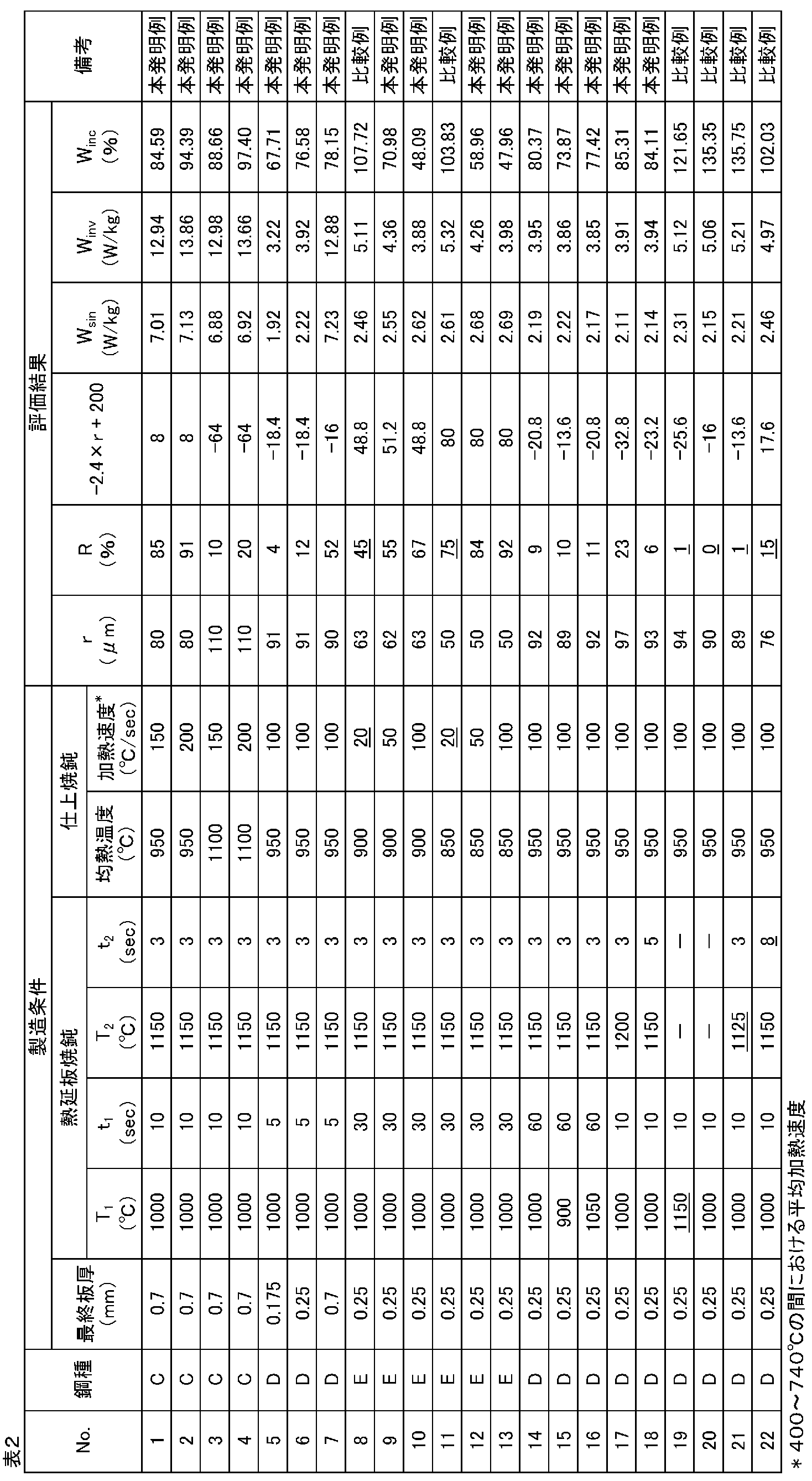
表3に示す成分組成を有する鋼を実験室で溶解し、鋳込んで鋼素材を得た。前記鋼素材に対して、次の(1)~(5)の処理を順次施して、無方向性電磁鋼板を作製した。
(1)板厚1.8mmへの熱間圧延、
(2)熱延板焼鈍、
(3)酸洗、
(4)最終板厚0.35mmへの冷間圧延、および
(5)均熱温度:900~1000℃、均熱時間:10sでの仕上焼鈍。 (Example 2)
Steel having the composition shown in Table 3 was melted in a laboratory and cast to obtain a steel material. The steel materials were sequentially subjected to the following treatments (1) to (5) to produce non-oriented electrical steel sheets.
(1) Hot rolling to a plate thickness of 1.8 mm,
(2) Hot-rolled sheet annealing,
(3) pickling,
(4) Cold rolling to a final sheet thickness of 0.35 mm, and (5) Finish annealing at a soaking temperature of 900 to 1000 ° C. and a soaking time of 10 s.
(2-1)均熱温度:1000℃、均熱時間:10sでの第1均熱処理、
(2-2)均熱温度:1150℃、均熱時間:3sでの第2均熱処理。 In the (2) hot-rolled sheet annealing, the following two-step soaking process comprising (2-1) and (2-2) was performed:
(2-1) Soaking temperature: 1000 ° C., soaking time: first soaking at 10 s,
(2-2) Soaking temperature: 1150 ° C., soaking time: 3 s Second soaking process.


Claims (8)
- 質量%で、
C :0.005%以下、
Si:4.5%以下、
Mn:0.02~2.0%、
Sol.Al:2.0%以下、
P :0.2%以下、
Ti:0.007%以下、
S :0.005%以下、ならびに
AsおよびPbから選択される1種または2種の合計:0.0005~0.005%、を含有し、
残部がFeおよび不可避的不純物からなる成分組成を有し、
平均結晶粒径rが40~120μmであり、
結晶粒径が板厚の1/6以下である結晶粒の合計面積の、鋼板の断面積に対する面積率Rが2%以上であり、かつ、前記平均結晶粒径r(μm)および前記面積率R(%)が下記(1)式の条件を満たす、無方向性電磁鋼板。
記
R>-2.4×r+200 …(1) % By mass
C: 0.005% or less,
Si: 4.5% or less,
Mn: 0.02 to 2.0%,
Sol. Al: 2.0% or less,
P: 0.2% or less,
Ti: 0.007% or less,
S: 0.005% or less, and a total of one or two selected from As and Pb: 0.0005 to 0.005%,
The balance has a component composition consisting of Fe and inevitable impurities,
The average grain size r is 40 to 120 μm,
The area ratio R of the total area of crystal grains whose crystal grain size is 1/6 or less of the plate thickness with respect to the cross-sectional area of the steel sheet is 2% or more, and the average crystal grain size r (μm) and the area ratio A non-oriented electrical steel sheet in which R (%) satisfies the condition of the following formula (1).
R> −2.4 × r + 200 (1) - 前記成分組成が、質量%で、
Sn:0.01~0.2%およびSb:0.01~0.2%から選択される1種または2種をさらに含む、請求項1に記載の無方向性電磁鋼板。 The component composition is mass%,
The non-oriented electrical steel sheet according to claim 1, further comprising one or two selected from Sn: 0.01 to 0.2% and Sb: 0.01 to 0.2%. - 前記成分組成が、質量%で、
REM:0.0005~0.005%、
Mg:0.0005~0.005%、および
Ca:0.0005~0.005%から選択される1種または2種以上をさらに含む、請求項1または2に記載の無方向性電磁鋼板。 The component composition is mass%,
REM: 0.0005 to 0.005%,
The non-oriented electrical steel sheet according to claim 1 or 2, further comprising one or more selected from Mg: 0.0005 to 0.005% and Ca: 0.0005 to 0.005%. - 板厚が0.35mm以下である、請求項1~3のいずれか一項に記載の無方向性電磁鋼板。 The non-oriented electrical steel sheet according to any one of claims 1 to 3, wherein the plate thickness is 0.35 mm or less.
- 磁路断面積70mm2のリング試験片に1次巻き数120ターン、2次巻き数100ターンの巻線を施したリング試験片で、インバータを用いたPWM制御により最大磁束密度1.5T、基本周波数50Hz、キャリア周波数1kHz、変調率0.4の励磁を行い測定した鉄損Winvと最大磁束密度1.5T、周波数50Hzの正弦波交流により励磁を行い測定した鉄損Wsinとから計算される鉄損増加率Winc(%)=100(Winv-Wsin)/Wsinが100%以下である、請求項1~4のいずれか一項に記載の無方向性電磁鋼板。 A ring test piece with a primary winding number of 120 turns and a secondary number of turns of 100 turns on a ring test piece with a magnetic path cross-sectional area of 70 mm 2 , with a maximum magnetic flux density of 1.5 T by PWM control using an inverter. Calculated from iron loss W inv measured by excitation with a frequency of 50 Hz, carrier frequency of 1 kHz, modulation factor of 0.4, and iron loss W sin measured by excitation with a sinusoidal alternating current with a maximum magnetic flux density of 1.5 T and a frequency of 50 Hz. The non-oriented electrical steel sheet according to any one of claims 1 to 4, wherein an increase rate of iron loss W inc (%) = 100 (W inv −W sin ) / W sin is 100% or less.
- 質量%で、
C :0.005%以下、
Si:4.5%以下、
Mn:0.02~2.0%、
Sol.Al:2.0%以下、
P :0.2%以下、
Ti:0.007%以下、
S :0.005%以下、ならびに
AsおよびPbから選択される1種または2種:合計で0.0005~0.005%、を含有し、
残部がFeおよび不可避的不純物からなる成分組成を有する鋼スラブを用意し、
前記鋼スラブを熱間圧延して熱延板とし、
前記熱延板に、均熱温度800~1100℃、均熱時間5min以下の条件で行う第1均熱処理と、均熱温度1150~1200℃、均熱時間5sec以下の条件で行う第2均熱処理からなる熱延板焼鈍を施し、
前記熱延板焼鈍された熱延板を、1回または中間焼鈍を挟む2回以上の冷間圧延によって最終板厚を有する鋼板とし、
前記冷間圧延後の鋼板に対して仕上焼鈍を施すことを含み、
前記仕上焼鈍での、400~740℃における加熱速度が30~300℃/secである、無方向性電磁鋼板の製造方法。 % By mass
C: 0.005% or less,
Si: 4.5% or less,
Mn: 0.02 to 2.0%,
Sol. Al: 2.0% or less,
P: 0.2% or less,
Ti: 0.007% or less,
S: 0.005% or less, and one or two selected from As and Pb: 0.0005 to 0.005% in total,
Prepare a steel slab having a component composition consisting of Fe and inevitable impurities in the balance,
Hot rolling the steel slab to make a hot rolled sheet,
A first soaking process performed on the hot-rolled sheet under conditions of a soaking temperature of 800 to 1100 ° C. and a soaking time of 5 minutes or less, and a second soaking process performed under conditions of a soaking temperature of 1150 to 1200 ° C. and a soaking time of 5 seconds or less. Hot-rolled sheet annealing consisting of
The hot-rolled sheet that has been subjected to hot-rolled sheet annealing is a steel sheet having a final sheet thickness by one or more cold rolling sandwiching intermediate annealing.
Including subjecting the steel sheet after cold rolling to finish annealing,
A method for producing a non-oriented electrical steel sheet, wherein a heating rate at 400 to 740 ° C. in the finish annealing is 30 to 300 ° C./sec. - 前記成分組成が、質量%で、
Sn:0.01~0.2%およびSb:0.01~0.2%から選択される1種または2種をさらに含む、請求項6に記載の無方向性電磁鋼板の製造方法。 The component composition is mass%,
The method for producing a non-oriented electrical steel sheet according to claim 6, further comprising one or two selected from Sn: 0.01 to 0.2% and Sb: 0.01 to 0.2%. - 前記成分組成が、質量%で、
REM:0.0005~0.005%、
Mg:0.0005~0.005%、および
Ca:0.0005~0.005%から選択される1種または2種以上をさらに含む、請求項6または7に記載の無方向性電磁鋼板の製造方法。 The component composition is mass%,
REM: 0.0005 to 0.005%,
The non-oriented electrical steel sheet according to claim 6 or 7, further comprising one or more selected from Mg: 0.0005 to 0.005% and Ca: 0.0005 to 0.005%. Production method.
Priority Applications (9)
| Application Number | Priority Date | Filing Date | Title |
|---|---|---|---|
| US16/065,352 US11114227B2 (en) | 2015-12-28 | 2016-12-14 | Non-oriented electrical steel sheet and method for manufacturing non-oriented electrical steel sheet |
| EP16881636.1A EP3399061B1 (en) | 2015-12-28 | 2016-12-14 | Non-oriented electrical steel sheet and method for manufacturing non-oriented electrical steel sheet |
| BR112018012496-6A BR112018012496B1 (en) | 2015-12-28 | 2016-12-14 | NON-ORIENTED ELECTROMAGNETIC STEEL SHEET AND METHOD FOR MANUFACTURING NON-ORIENTED ELECTROMAGNETIC STEEL SHEET |
| MX2018007972A MX2018007972A (en) | 2015-12-28 | 2016-12-14 | Non-oriented electromagnetic steel sheet and method for producing non-oriented electromagnetic steel sheet. |
| KR1020187018262A KR102104769B1 (en) | 2015-12-28 | 2016-12-14 | Non-oriented electrical steel sheet and method for manufacturing non-oriented electrical steel sheet |
| CA3008588A CA3008588C (en) | 2015-12-28 | 2016-12-14 | Non-oriented electrical steel sheet and method for manufacturing non-oriented electrical steel sheet |
| CN201680076599.4A CN108474070B (en) | 2015-12-28 | 2016-12-14 | Non-oriented electrical steel sheet and method for producing non-oriented electrical steel sheet |
| RU2018127378A RU2686712C1 (en) | 2015-12-28 | 2016-12-14 | Sheet from non-textured electrical steel and method for production of sheet from non-textured electrical steel |
| JP2017521604A JP6210182B1 (en) | 2015-12-28 | 2016-12-14 | Non-oriented electrical steel sheet and method for producing non-oriented electrical steel sheet |
Applications Claiming Priority (2)
| Application Number | Priority Date | Filing Date | Title |
|---|---|---|---|
| JP2015-256634 | 2015-12-28 | ||
| JP2015256634 | 2015-12-28 |
Publications (1)
| Publication Number | Publication Date |
|---|---|
| WO2017115657A1 true WO2017115657A1 (en) | 2017-07-06 |
Family
ID=59224934
Family Applications (1)
| Application Number | Title | Priority Date | Filing Date |
|---|---|---|---|
| PCT/JP2016/087279 WO2017115657A1 (en) | 2015-12-28 | 2016-12-14 | Non-oriented electromagnetic steel sheet and method for producing non-oriented electromagnetic steel sheet |
Country Status (11)
| Country | Link |
|---|---|
| US (1) | US11114227B2 (en) |
| EP (1) | EP3399061B1 (en) |
| JP (1) | JP6210182B1 (en) |
| KR (1) | KR102104769B1 (en) |
| CN (1) | CN108474070B (en) |
| BR (1) | BR112018012496B1 (en) |
| CA (1) | CA3008588C (en) |
| MX (1) | MX2018007972A (en) |
| RU (1) | RU2686712C1 (en) |
| TW (1) | TWI623629B (en) |
| WO (1) | WO2017115657A1 (en) |
Cited By (7)
| Publication number | Priority date | Publication date | Assignee | Title |
|---|---|---|---|---|
| KR20190078155A (en) * | 2017-12-26 | 2019-07-04 | 주식회사 포스코 | Non-oriented electrical steel sheet and method for manufacturing the same |
| JP2019178374A (en) * | 2018-03-30 | 2019-10-17 | 日本製鉄株式会社 | Non-oriented electromagnetic steel sheet and manufacturing method therefor, and motor core and manufacturing method therefor |
| CN112912186A (en) * | 2018-10-24 | 2021-06-04 | 日本制铁株式会社 | Non-oriented magnetic steel sheet and method for manufacturing laminated iron core using same |
| CN113166873A (en) * | 2018-09-27 | 2021-07-23 | Posco公司 | Non-oriented electrical steel sheet and method for manufacturing the same |
| JP2022503910A (en) * | 2018-09-27 | 2022-01-12 | ポスコ | Non-oriented electrical steel sheet and its manufacturing method |
| JP2022545793A (en) * | 2019-08-26 | 2022-10-31 | 宝山鋼鉄股▲ふん▼有限公司 | Non-oriented electrical steel sheet and manufacturing method thereof |
| WO2024071628A1 (en) * | 2022-09-30 | 2024-04-04 | 현대제철 주식회사 | Non-oriented electrical steel sheet and manufacturing method therefor |
Families Citing this family (15)
| Publication number | Priority date | Publication date | Assignee | Title |
|---|---|---|---|---|
| KR101901313B1 (en) * | 2016-12-19 | 2018-09-21 | 주식회사 포스코 | Non-oriented electrical steel sheet and method for manufacturing the same |
| WO2019160108A1 (en) | 2018-02-16 | 2019-08-22 | 日本製鉄株式会社 | Non-oriented electromagnetic steel sheet, and production method for non-oriented electromagnetic steel sheet |
| US20210343458A1 (en) * | 2018-11-02 | 2021-11-04 | Nippon Steel Corporation | Non-oriented electrical steel sheet |
| JP7192887B2 (en) * | 2019-01-17 | 2022-12-20 | 日本製鉄株式会社 | Non-oriented electrical steel sheet, split type stator and rotating electric machine |
| CN112143963A (en) * | 2019-06-28 | 2020-12-29 | 宝山钢铁股份有限公司 | Non-oriented electrical steel plate with excellent magnetic property and continuous annealing method thereof |
| CN112143961A (en) * | 2019-06-28 | 2020-12-29 | 宝山钢铁股份有限公司 | Non-oriented electrical steel plate with excellent magnetic property and continuous annealing method thereof |
| CN112143964A (en) * | 2019-06-28 | 2020-12-29 | 宝山钢铁股份有限公司 | Non-oriented electrical steel plate with extremely low iron loss and continuous annealing process thereof |
| CN112143962A (en) * | 2019-06-28 | 2020-12-29 | 宝山钢铁股份有限公司 | Non-oriented electrical steel plate with high magnetic induction and low iron loss and manufacturing method thereof |
| CN112430778A (en) * | 2019-08-26 | 2021-03-02 | 宝山钢铁股份有限公司 | Thin non-oriented electrical steel plate and manufacturing method thereof |
| KR102278897B1 (en) * | 2019-12-19 | 2021-07-16 | 주식회사 포스코 | Non-oriented electrical steel sheet and method for manufacturing the same |
| DE102021201616A1 (en) * | 2020-05-29 | 2021-12-02 | Sms Group Gmbh | Process for the recrystallizing annealing of a non-grain-oriented electrical steel |
| CN112143974B (en) * | 2020-09-27 | 2021-10-22 | 江苏省沙钢钢铁研究院有限公司 | Production method of non-oriented silicon steel and non-oriented silicon steel |
| KR102515028B1 (en) * | 2021-02-10 | 2023-03-27 | 엘지전자 주식회사 | Method for manufactruing non-oriented electrical steel sheet and non-oriented electrical steel sheet prepared by the same |
| KR20230095256A (en) * | 2021-12-22 | 2023-06-29 | 주식회사 포스코 | Non-oriented electrical steel sheet and method for manufacturing the same |
| KR20230096881A (en) * | 2021-12-22 | 2023-06-30 | 주식회사 포스코 | Non-oriented electrical steel sheet and method for manufacturing the same |
Citations (6)
| Publication number | Priority date | Publication date | Assignee | Title |
|---|---|---|---|---|
| JPH1025554A (en) | 1996-07-10 | 1998-01-27 | Nippon Steel Corp | Nonoriented silicon steel sheet for inverter controlling compressor motor |
| JP2001049340A (en) * | 1999-08-10 | 2001-02-20 | Nippon Steel Corp | Production of nonoriented silicon steel sheet good in magnetic flux density and iron loss and its production |
| JP2001279403A (en) | 2000-03-31 | 2001-10-10 | Kawasaki Steel Corp | Nonoriented silicon steel sheet excellent in high frequency magnetic property |
| JP2002294417A (en) | 2001-04-02 | 2002-10-09 | Nkk Corp | Non-oriented electromagnetic steel sheet superior in fatigue characteristics |
| JP2007247047A (en) * | 2006-03-20 | 2007-09-27 | Nippon Steel Corp | Non-oriented electromagnetic steel sheet |
| JP4860783B2 (en) | 2010-02-25 | 2012-01-25 | 新日本製鐵株式会社 | Non-oriented electrical steel sheet |
Family Cites Families (17)
| Publication number | Priority date | Publication date | Assignee | Title |
|---|---|---|---|---|
| KR970007160B1 (en) * | 1994-11-16 | 1997-05-03 | 포항종합제철 주식회사 | Making method of non oriented electrical steel sheet having high tensile strength |
| JP2002294414A (en) | 2001-03-29 | 2002-10-09 | Nkk Corp | Non-oriented electromagnetic steel sheet superior in workability, and manufacturing method therefor |
| JP4718749B2 (en) | 2002-08-06 | 2011-07-06 | Jfeスチール株式会社 | High magnetic flux density non-oriented electrical steel sheet for rotating machine and member for rotating machine |
| US7470333B2 (en) * | 2003-05-06 | 2008-12-30 | Nippon Steel Corp. | Non-oriented electrical steel sheet excellent in core loss and manufacturing method thereof |
| JP4681450B2 (en) * | 2005-02-23 | 2011-05-11 | 新日本製鐵株式会社 | Non-oriented electrical steel sheet with excellent magnetic properties in the rolling direction and manufacturing method thereof |
| KR100978859B1 (en) * | 2008-07-11 | 2010-08-31 | 피에스케이 주식회사 | Apparatus for generating hollow cathode plasma and apparatus for treating a large area substrate by hollow cathode plasma |
| CN102453844B (en) * | 2010-10-25 | 2013-09-04 | 宝山钢铁股份有限公司 | Method for preparing non-oriented silicon steel with excellent magnetic property and high efficiency |
| JP5668460B2 (en) * | 2010-12-22 | 2015-02-12 | Jfeスチール株式会社 | Method for producing non-oriented electrical steel sheet |
| CA2822206C (en) * | 2011-02-24 | 2016-09-13 | Jfe Steel Corporation | Non-oriented electrical steel sheet and method for manufacturing the same |
| JP5824965B2 (en) * | 2011-08-23 | 2015-12-02 | 新日鐵住金株式会社 | Method for producing non-oriented electrical steel sheet |
| WO2013058239A1 (en) * | 2011-10-20 | 2013-04-25 | Jfeスチール株式会社 | Oriented electromagnetic steel sheet and method for manufacturing same |
| CN103305659B (en) * | 2012-03-08 | 2016-03-30 | 宝山钢铁股份有限公司 | The non-oriented electromagnetic steel sheet of excellent magnetic and calcium treating method thereof |
| JP5892327B2 (en) * | 2012-03-15 | 2016-03-23 | Jfeスチール株式会社 | Method for producing non-oriented electrical steel sheet |
| JP5533958B2 (en) * | 2012-08-21 | 2014-06-25 | Jfeスチール株式会社 | Non-oriented electrical steel sheet with low iron loss degradation by punching |
| US20150243419A1 (en) | 2012-09-27 | 2015-08-27 | Jef Steel Corporation | Method for producing grain-oriented electrical steel sheet |
| JP5668767B2 (en) * | 2013-02-22 | 2015-02-12 | Jfeスチール株式会社 | Hot rolled steel sheet for manufacturing non-oriented electrical steel sheet and method for manufacturing the same |
| JP6057082B2 (en) * | 2013-03-13 | 2017-01-11 | Jfeスチール株式会社 | Non-oriented electrical steel sheet with excellent magnetic properties |
-
2016
- 2016-12-14 MX MX2018007972A patent/MX2018007972A/en unknown
- 2016-12-14 RU RU2018127378A patent/RU2686712C1/en active
- 2016-12-14 US US16/065,352 patent/US11114227B2/en active Active
- 2016-12-14 CN CN201680076599.4A patent/CN108474070B/en active Active
- 2016-12-14 EP EP16881636.1A patent/EP3399061B1/en active Active
- 2016-12-14 JP JP2017521604A patent/JP6210182B1/en active Active
- 2016-12-14 CA CA3008588A patent/CA3008588C/en active Active
- 2016-12-14 BR BR112018012496-6A patent/BR112018012496B1/en active IP Right Grant
- 2016-12-14 WO PCT/JP2016/087279 patent/WO2017115657A1/en active Application Filing
- 2016-12-14 KR KR1020187018262A patent/KR102104769B1/en active IP Right Grant
- 2016-12-22 TW TW105142630A patent/TWI623629B/en active
Patent Citations (6)
| Publication number | Priority date | Publication date | Assignee | Title |
|---|---|---|---|---|
| JPH1025554A (en) | 1996-07-10 | 1998-01-27 | Nippon Steel Corp | Nonoriented silicon steel sheet for inverter controlling compressor motor |
| JP2001049340A (en) * | 1999-08-10 | 2001-02-20 | Nippon Steel Corp | Production of nonoriented silicon steel sheet good in magnetic flux density and iron loss and its production |
| JP2001279403A (en) | 2000-03-31 | 2001-10-10 | Kawasaki Steel Corp | Nonoriented silicon steel sheet excellent in high frequency magnetic property |
| JP2002294417A (en) | 2001-04-02 | 2002-10-09 | Nkk Corp | Non-oriented electromagnetic steel sheet superior in fatigue characteristics |
| JP2007247047A (en) * | 2006-03-20 | 2007-09-27 | Nippon Steel Corp | Non-oriented electromagnetic steel sheet |
| JP4860783B2 (en) | 2010-02-25 | 2012-01-25 | 新日本製鐵株式会社 | Non-oriented electrical steel sheet |
Non-Patent Citations (2)
| Title |
|---|
| MASANORI UESAKA ET AL.: "Influence of Thickness of Non-Oriented Electrical Steel on Iron loss under Inverter Excitation", THE INSTITUTE OF ELECTRICAL ENGINEERS OF JAPAN KENKYUKAI SHIRYO MAGNETICS/LINEAR DRIVES GODO KENKYUKAI, 15 December 2015 (2015-12-15), pages 1 - 6 * |
| YOSHIHIRO ARITA ET AL.: "Abnormal grain growth of Non-oriented Electrical Steel Sheets", CURRENT ADVANCES IN MATERIALS AND PROCESSES, vol. 17, no. 6, 1 September 2004 (2004-09-01), pages 1328 * |
Cited By (15)
| Publication number | Priority date | Publication date | Assignee | Title |
|---|---|---|---|---|
| US11408041B2 (en) | 2017-12-26 | 2022-08-09 | Posco | Non-oriented electrical steel sheet and method for producing same |
| KR102009392B1 (en) | 2017-12-26 | 2019-08-09 | 주식회사 포스코 | Non-oriented electrical steel sheet and method for manufacturing the same |
| KR20190078155A (en) * | 2017-12-26 | 2019-07-04 | 주식회사 포스코 | Non-oriented electrical steel sheet and method for manufacturing the same |
| JP2019178374A (en) * | 2018-03-30 | 2019-10-17 | 日本製鉄株式会社 | Non-oriented electromagnetic steel sheet and manufacturing method therefor, and motor core and manufacturing method therefor |
| JP7352057B2 (en) | 2018-03-30 | 2023-09-28 | 日本製鉄株式会社 | Non-oriented electrical steel sheet and its manufacturing method, motor core and its manufacturing method |
| JP7245325B2 (en) | 2018-09-27 | 2023-03-23 | ポスコ カンパニー リミテッド | Non-oriented electrical steel sheet and manufacturing method thereof |
| JP2022503910A (en) * | 2018-09-27 | 2022-01-12 | ポスコ | Non-oriented electrical steel sheet and its manufacturing method |
| JP2022502572A (en) * | 2018-09-27 | 2022-01-11 | ポスコPosco | Non-oriented electrical steel sheet and its manufacturing method |
| CN113166873A (en) * | 2018-09-27 | 2021-07-23 | Posco公司 | Non-oriented electrical steel sheet and method for manufacturing the same |
| CN113166873B (en) * | 2018-09-27 | 2023-05-26 | 浦项控股股份有限公司 | Non-oriented electrical steel sheet and method for manufacturing same |
| JP7445651B2 (en) | 2018-09-27 | 2024-03-07 | ポスコ カンパニー リミテッド | Non-oriented electrical steel sheet and its manufacturing method |
| CN112912186A (en) * | 2018-10-24 | 2021-06-04 | 日本制铁株式会社 | Non-oriented magnetic steel sheet and method for manufacturing laminated iron core using same |
| JP2022545793A (en) * | 2019-08-26 | 2022-10-31 | 宝山鋼鉄股▲ふん▼有限公司 | Non-oriented electrical steel sheet and manufacturing method thereof |
| JP7378585B2 (en) | 2019-08-26 | 2023-11-13 | 宝山鋼鉄股▲ふん▼有限公司 | Non-oriented electrical steel sheet and its manufacturing method |
| WO2024071628A1 (en) * | 2022-09-30 | 2024-04-04 | 현대제철 주식회사 | Non-oriented electrical steel sheet and manufacturing method therefor |
Also Published As
| Publication number | Publication date |
|---|---|
| KR20180087374A (en) | 2018-08-01 |
| KR102104769B1 (en) | 2020-04-27 |
| RU2686712C1 (en) | 2019-04-30 |
| EP3399061B1 (en) | 2020-06-17 |
| JPWO2017115657A1 (en) | 2017-12-28 |
| EP3399061A1 (en) | 2018-11-07 |
| BR112018012496B1 (en) | 2022-02-15 |
| CA3008588A1 (en) | 2017-07-06 |
| EP3399061A4 (en) | 2018-11-07 |
| JP6210182B1 (en) | 2017-10-11 |
| US20190189318A1 (en) | 2019-06-20 |
| BR112018012496A2 (en) | 2018-12-11 |
| CN108474070B (en) | 2021-01-12 |
| TWI623629B (en) | 2018-05-11 |
| US11114227B2 (en) | 2021-09-07 |
| CA3008588C (en) | 2020-09-01 |
| CN108474070A (en) | 2018-08-31 |
| MX2018007972A (en) | 2018-11-09 |
| TW201726944A (en) | 2017-08-01 |
Similar Documents
| Publication | Publication Date | Title |
|---|---|---|
| JP6210182B1 (en) | Non-oriented electrical steel sheet and method for producing non-oriented electrical steel sheet | |
| JP7066782B2 (en) | Manufacturing method of tin-containing non-directional silicon steel sheet, obtained steel sheet and use of the steel sheet | |
| KR101945132B1 (en) | Non-oriented electrical steel sheet and method for producing the same, and motor core and mehod of producing the same | |
| TWI525197B (en) | High magnetic flux density non-directional electromagnetic steel plate and motor | |
| TWI516612B (en) | Method for manufacturing non - directional electromagnetic steel sheet | |
| JP6913683B2 (en) | Non-oriented electrical steel sheet and its manufacturing method | |
| WO2013069754A1 (en) | Anisotropic electromagnetic steel sheet and method for producing same | |
| KR20150093807A (en) | Production method for semi-processed non-oriented electromagnetic steel sheet exhibiting superior magnetic properties | |
| JP2011084761A (en) | Non-oriented electromagnetic steel sheet for rotor and manufacturing method therefor | |
| JP2014037581A (en) | Method for producing nonoriented silicon steel sheet | |
| TWI525198B (en) | Non - directional electrical steel sheet and its hot - rolled steel sheet | |
| JP2020509184A (en) | Non-oriented electrical steel sheet and manufacturing method thereof | |
| KR20180011809A (en) | Method for manufacturing non-oriented electromagnetic steel sheet with excellent magnetic properties | |
| JP2016089198A (en) | Manufacturing method of oriented electromagnetic steel sheet excellent in magnetic properties | |
| JP6763148B2 (en) | Non-oriented electrical steel sheet | |
| JP5724837B2 (en) | Non-oriented electrical steel sheet and manufacturing method thereof | |
| JP7350069B2 (en) | Non-oriented electrical steel sheet and its manufacturing method | |
| JP6123234B2 (en) | Electrical steel sheet | |
| JP7445656B2 (en) | Non-oriented electrical steel sheet and its manufacturing method |
Legal Events
| Date | Code | Title | Description |
|---|---|---|---|
| ENP | Entry into the national phase |
Ref document number: 2017521604 Country of ref document: JP Kind code of ref document: A |
|
| 121 | Ep: the epo has been informed by wipo that ep was designated in this application |
Ref document number: 16881636 Country of ref document: EP Kind code of ref document: A1 |
|
| ENP | Entry into the national phase |
Ref document number: 3008588 Country of ref document: CA |
|
| REG | Reference to national code |
Ref country code: BR Ref legal event code: B01A Ref document number: 112018012496 Country of ref document: BR |
|
| ENP | Entry into the national phase |
Ref document number: 20187018262 Country of ref document: KR Kind code of ref document: A |
|
| WWE | Wipo information: entry into national phase |
Ref document number: MX/A/2018/007972 Country of ref document: MX |
|
| NENP | Non-entry into the national phase |
Ref country code: DE |
|
| WWE | Wipo information: entry into national phase |
Ref document number: 2016881636 Country of ref document: EP |
|
| ENP | Entry into the national phase |
Ref document number: 2016881636 Country of ref document: EP Effective date: 20180730 |
|
| ENP | Entry into the national phase |
Ref document number: 112018012496 Country of ref document: BR Kind code of ref document: A2 Effective date: 20180619 |