WO2017115565A1 - 垂直型風力発電システム、垂直型水力発電システム、およびその制御方法 - Google Patents
垂直型風力発電システム、垂直型水力発電システム、およびその制御方法 Download PDFInfo
- Publication number
- WO2017115565A1 WO2017115565A1 PCT/JP2016/083632 JP2016083632W WO2017115565A1 WO 2017115565 A1 WO2017115565 A1 WO 2017115565A1 JP 2016083632 W JP2016083632 W JP 2016083632W WO 2017115565 A1 WO2017115565 A1 WO 2017115565A1
- Authority
- WO
- WIPO (PCT)
- Prior art keywords
- vertical
- blade
- power generation
- generation system
- angle
- Prior art date
Links
- 238000010248 power generation Methods 0.000 title claims abstract description 401
- 238000000034 method Methods 0.000 title claims abstract description 13
- 238000009826 distribution Methods 0.000 claims abstract description 130
- 238000001514 detection method Methods 0.000 claims abstract description 31
- 230000002093 peripheral effect Effects 0.000 claims description 150
- XLYOFNOQVPJJNP-UHFFFAOYSA-N water Substances O XLYOFNOQVPJJNP-UHFFFAOYSA-N 0.000 claims description 63
- 230000008859 change Effects 0.000 claims description 19
- 230000004907 flux Effects 0.000 claims description 13
- 230000007246 mechanism Effects 0.000 claims description 13
- 230000001133 acceleration Effects 0.000 claims description 10
- 230000007423 decrease Effects 0.000 claims description 9
- 230000003247 decreasing effect Effects 0.000 claims description 5
- 238000007689 inspection Methods 0.000 claims description 5
- 238000012423 maintenance Methods 0.000 claims description 4
- 238000006243 chemical reaction Methods 0.000 abstract description 79
- 230000008878 coupling Effects 0.000 abstract description 13
- 238000010168 coupling process Methods 0.000 abstract description 13
- 238000005859 coupling reaction Methods 0.000 abstract description 13
- 239000012141 concentrate Substances 0.000 abstract description 6
- 230000000694 effects Effects 0.000 description 46
- 238000010586 diagram Methods 0.000 description 38
- 230000006872 improvement Effects 0.000 description 28
- 238000011144 upstream manufacturing Methods 0.000 description 24
- 238000004364 calculation method Methods 0.000 description 17
- 230000001629 suppression Effects 0.000 description 12
- 239000012530 fluid Substances 0.000 description 9
- 230000006870 function Effects 0.000 description 7
- 230000005540 biological transmission Effects 0.000 description 6
- 238000005192 partition Methods 0.000 description 6
- 230000007613 environmental effect Effects 0.000 description 5
- 230000014509 gene expression Effects 0.000 description 3
- 230000008569 process Effects 0.000 description 3
- 238000011084 recovery Methods 0.000 description 3
- 230000009467 reduction Effects 0.000 description 3
- 230000032683 aging Effects 0.000 description 2
- 238000004458 analytical method Methods 0.000 description 2
- 239000003638 chemical reducing agent Substances 0.000 description 2
- 239000000470 constituent Substances 0.000 description 2
- 230000006866 deterioration Effects 0.000 description 2
- 230000005611 electricity Effects 0.000 description 2
- 230000005764 inhibitory process Effects 0.000 description 2
- 230000004044 response Effects 0.000 description 2
- 230000035882 stress Effects 0.000 description 2
- 230000001419 dependent effect Effects 0.000 description 1
- 238000013461 design Methods 0.000 description 1
- 238000005516 engineering process Methods 0.000 description 1
- ZZUFCTLCJUWOSV-UHFFFAOYSA-N furosemide Chemical compound C1=C(Cl)C(S(=O)(=O)N)=CC(C(O)=O)=C1NCC1=CC=CO1 ZZUFCTLCJUWOSV-UHFFFAOYSA-N 0.000 description 1
- 230000020169 heat generation Effects 0.000 description 1
- 238000013507 mapping Methods 0.000 description 1
- 239000002184 metal Substances 0.000 description 1
- 229910052751 metal Inorganic materials 0.000 description 1
- 238000012986 modification Methods 0.000 description 1
- 230000004048 modification Effects 0.000 description 1
- 238000012545 processing Methods 0.000 description 1
- 238000011160 research Methods 0.000 description 1
- 238000009751 slip forming Methods 0.000 description 1
- 239000007858 starting material Substances 0.000 description 1
Images


Classifications
-
- F—MECHANICAL ENGINEERING; LIGHTING; HEATING; WEAPONS; BLASTING
- F03—MACHINES OR ENGINES FOR LIQUIDS; WIND, SPRING, OR WEIGHT MOTORS; PRODUCING MECHANICAL POWER OR A REACTIVE PROPULSIVE THRUST, NOT OTHERWISE PROVIDED FOR
- F03B—MACHINES OR ENGINES FOR LIQUIDS
- F03B7/00—Water wheels
-
- F—MECHANICAL ENGINEERING; LIGHTING; HEATING; WEAPONS; BLASTING
- F03—MACHINES OR ENGINES FOR LIQUIDS; WIND, SPRING, OR WEIGHT MOTORS; PRODUCING MECHANICAL POWER OR A REACTIVE PROPULSIVE THRUST, NOT OTHERWISE PROVIDED FOR
- F03B—MACHINES OR ENGINES FOR LIQUIDS
- F03B15/00—Controlling
- F03B15/02—Controlling by varying liquid flow
- F03B15/04—Controlling by varying liquid flow of turbines
-
- F—MECHANICAL ENGINEERING; LIGHTING; HEATING; WEAPONS; BLASTING
- F03—MACHINES OR ENGINES FOR LIQUIDS; WIND, SPRING, OR WEIGHT MOTORS; PRODUCING MECHANICAL POWER OR A REACTIVE PROPULSIVE THRUST, NOT OTHERWISE PROVIDED FOR
- F03D—WIND MOTORS
- F03D3/00—Wind motors with rotation axis substantially perpendicular to the air flow entering the rotor
- F03D3/02—Wind motors with rotation axis substantially perpendicular to the air flow entering the rotor having a plurality of rotors
-
- F—MECHANICAL ENGINEERING; LIGHTING; HEATING; WEAPONS; BLASTING
- F03—MACHINES OR ENGINES FOR LIQUIDS; WIND, SPRING, OR WEIGHT MOTORS; PRODUCING MECHANICAL POWER OR A REACTIVE PROPULSIVE THRUST, NOT OTHERWISE PROVIDED FOR
- F03D—WIND MOTORS
- F03D3/00—Wind motors with rotation axis substantially perpendicular to the air flow entering the rotor
- F03D3/04—Wind motors with rotation axis substantially perpendicular to the air flow entering the rotor having stationary wind-guiding means, e.g. with shrouds or channels
-
- F—MECHANICAL ENGINEERING; LIGHTING; HEATING; WEAPONS; BLASTING
- F03—MACHINES OR ENGINES FOR LIQUIDS; WIND, SPRING, OR WEIGHT MOTORS; PRODUCING MECHANICAL POWER OR A REACTIVE PROPULSIVE THRUST, NOT OTHERWISE PROVIDED FOR
- F03D—WIND MOTORS
- F03D3/00—Wind motors with rotation axis substantially perpendicular to the air flow entering the rotor
- F03D3/06—Rotors
-
- F—MECHANICAL ENGINEERING; LIGHTING; HEATING; WEAPONS; BLASTING
- F03—MACHINES OR ENGINES FOR LIQUIDS; WIND, SPRING, OR WEIGHT MOTORS; PRODUCING MECHANICAL POWER OR A REACTIVE PROPULSIVE THRUST, NOT OTHERWISE PROVIDED FOR
- F03D—WIND MOTORS
- F03D7/00—Controlling wind motors
- F03D7/06—Controlling wind motors the wind motors having rotation axis substantially perpendicular to the air flow entering the rotor
-
- Y—GENERAL TAGGING OF NEW TECHNOLOGICAL DEVELOPMENTS; GENERAL TAGGING OF CROSS-SECTIONAL TECHNOLOGIES SPANNING OVER SEVERAL SECTIONS OF THE IPC; TECHNICAL SUBJECTS COVERED BY FORMER USPC CROSS-REFERENCE ART COLLECTIONS [XRACs] AND DIGESTS
- Y02—TECHNOLOGIES OR APPLICATIONS FOR MITIGATION OR ADAPTATION AGAINST CLIMATE CHANGE
- Y02E—REDUCTION OF GREENHOUSE GAS [GHG] EMISSIONS, RELATED TO ENERGY GENERATION, TRANSMISSION OR DISTRIBUTION
- Y02E10/00—Energy generation through renewable energy sources
- Y02E10/20—Hydro energy
-
- Y—GENERAL TAGGING OF NEW TECHNOLOGICAL DEVELOPMENTS; GENERAL TAGGING OF CROSS-SECTIONAL TECHNOLOGIES SPANNING OVER SEVERAL SECTIONS OF THE IPC; TECHNICAL SUBJECTS COVERED BY FORMER USPC CROSS-REFERENCE ART COLLECTIONS [XRACs] AND DIGESTS
- Y02—TECHNOLOGIES OR APPLICATIONS FOR MITIGATION OR ADAPTATION AGAINST CLIMATE CHANGE
- Y02E—REDUCTION OF GREENHOUSE GAS [GHG] EMISSIONS, RELATED TO ENERGY GENERATION, TRANSMISSION OR DISTRIBUTION
- Y02E10/00—Energy generation through renewable energy sources
- Y02E10/70—Wind energy
- Y02E10/74—Wind turbines with rotation axis perpendicular to the wind direction
Definitions
- the present invention relates to a wind power generation system that converts wind energy into blade rotation energy and converts the rotation energy into electrical energy, and particularly relates to a significant improvement in blade rotation energy in a vertical wind power generation system. It is. Moreover, by changing the fluid from wind to water, the application field of the present technology can be expanded to the field of hydroelectric power generation.
- the horizontal type has a high blade rotation speed and generates wind noise, and the wind direction that can generate power is limited, so a mechanism that always follows the wind direction is required. It has the problem of becoming.
- the vertical type has a relatively low rotational speed and is less concerned about noise, and it is not necessary to consider the direction of the wind, but it is known that the conversion efficiency to rotational energy (rotational energy conversion efficiency) is relatively low. Yes.
- the rotational energy conversion efficiency is defined as Cp as the rotational energy conversion efficiency, which is the conversion efficiency (%) for converting the kinetic energy of the wind that passes through the blade wind receiving area per unit time into the rotational energy of the blade.
- the value obtained by dividing the rotational energy (W) by the angular velocity ⁇ (rad / s) becomes the rotational torque (N ⁇ m) by the rotational force in the tangential direction of the entire vertical blade as the cylindrical rotating body.
- the wind energy is represented by 1 / 2 ⁇ AV 3 , A is the wind receiving area (diameter ⁇ wing length) (m 2 ) of the vertical blade, V is the wind speed (m / s), ⁇ is the air density (kg / m 3 ).
- Patent Document 1 Patent Document 2
- Patent Document 1 a vertical wind power generation system having a configuration in which a part of the airfoil is cut away to increase the drag and a configuration in which the blade is rotated by using a cam or a link mechanism.
- Patent Document 2 Patent Document 2
- the notch portion 22 is formed in the rear edge portion, when the blade 20 receives wind from behind and rotates, A large air resistance is generated in the blade 20 by the notch 22, and a rotational moment is generated in the blade 20 by a semi-cylindrical type cup-type windmill effect so that a starting torque of the windmill is generated.
- Patent Document 2 as shown in FIG. 6 of Patent Document 2, the magnitude of the lift is changed by changing the angle of the blade 3 using a cam or link mechanism to increase the lift at low speed, It is configured to reduce the lift that is sometimes generated. Furthermore, in Patent Document 3, as shown in FIG. 1 of Patent Document 3, the startup characteristics are improved by mounting a plurality of blades on the rotor 4.
- the conventional vertical wind power generation system described above has a rotational torque of any design conditions (relationship between solidity, angle of attack and lift and drag, conditions of blade mounting angle, and peripheral speed ratio). Whether it increases, how the peripheral speed ratio, blade performance and Reynolds number are related, what happens if the airfoil changes, rotational torque and solidity when arranged concentrically, peripheral speed ratio, wind speed, The most essential considerations such as the relationship with the angle of attack are not discussed or disclosed.
- the blade rotation torque can be reduced slightly even in response to excessive wind force during strong winds, and it is difficult to accurately control blade rotation against actual strong winds, which is long in strength.
- the problem of being unsuitable for time operation occurs, and the life and reliability of the vertical wind power generation system become major issues.
- cams and links are only effective in a specific wind direction, and if the wind direction changes, conversely the rotational energy conversion efficiency deteriorates, the adjustment range is narrow, and what angle adjustment is performed, There was a problem that the degree of the effect was not considered at all.
- Patent Document 3 proposes that a concentric double blade is configured to improve the start-up characteristics, and that the start-up characteristics are improved and the rotational force can be increased even at high speed rotation. ing.
- a concentric double blade is configured to improve the start-up characteristics, and that the start-up characteristics are improved and the rotational force can be increased even at high speed rotation.
- there is no mention of what kind of configuration will improve the start-up characteristics or why the start-up characteristics improve, and theoretical considerations based on relationships with solidity, rotation speed, wind speed, etc. It has not been.
- the solidity, arrangement, and relative angle of the blades are essential consideration factors, and it is difficult to improve the starting characteristics without these factors.
- whether or not the rotational torque is increased during high-speed rotation is determined by the blade solidity, arrangement, relative angle, etc., but no consideration is given regarding this point.
- Blade characteristics that take into account all of these factors, including blade characteristics such as lift and drag, blade size, number of blades, solidity, and relative angle of blades, are important factors in improving starting characteristics and characteristics during high-speed rotation.
- the configuration is an indispensable requirement, and if this point is not taken into consideration, the start-up characteristics and the power generation efficiency cannot be significantly improved.
- the configuration described in Patent Document 3 even if the starting characteristics slightly change, the inner blade becomes a resistance during normal rotation or high-speed rotation, and on the contrary, the power generation efficiency is greatly reduced. The desired effects such as significant improvement in starting characteristics and power generation efficiency cannot be obtained.
- the blade rotation cannot be started at the time of light wind, the power generation efficiency at the average wind speed is reduced, and it is difficult to control the rotation speed at the time of strong wind. There is a problem that it is not suitable for driving time.
- the rotational energy conversion efficiency (Cp) that converts the kinetic energy of the wind into the rotational energy of the blade is improved, and various wind conditions are used in the electrical energy conversion that converts the rotational energy into electrical energy. It is important to always convert electric energy as much as possible. Therefore, it is desirable to generate electricity by converting wind kinetic energy into electrical energy even in a situation where the wind speed is as high as possible.
- the challenges of a vertical wind power generation system with high power generation efficiency are the startability of the blades from low wind speeds (light winds), significant improvement in rotational energy conversion efficiency in wind conditions from low wind speeds to strong winds, Power generation under excessive wind energy conditions.
- the generator outputs a predetermined amount of power according to the number of revolutions.
- the size including the drastic improvement in withstand voltage specifications and heat generation during load fluctuation
- the size including the drastic improvement in withstand voltage specifications and heat generation during load fluctuation
- the present invention has been made in view of such circumstances, and effectively controls the occurrence of lift and drag in various wind conditions and wind speeds with concentric blades and each blade.
- the starting characteristics at the time of light wind are greatly improved compared to the conventional type, realizing excellent self-starting performance and enabling efficient power generation from the speed of light wind.
- a configuration that greatly improves power generation efficiency at wind speed has been realized.
- the blade can efficiently reduce the rotational energy and control the blade rotation speed with high accuracy during strong winds, and achieve a significant improvement in power generation efficiency and a significant improvement in reliability and life.
- a vertical wind power generation system capable of Furthermore, it is possible to realize a vertical wind power generation system with higher energy conversion efficiency by changing the intensity distribution of the energy of the incoming wind according to the wind speed and the rotational speed of the blade.
- the fluid is air as described above. However, the fluid can be replaced with water and similarly considered as a hydroelectric power generation system.
- Reynolds number Re (speed) (representative length) / (kinematic viscosity). If the relative speed is the same for the same airfoil, the Reynolds number is about 17 times that of air. The higher the Reynolds number, the better the airfoil characteristics (the lift coefficient increases). Therefore, if the flow velocity is the same, the rotational energy conversion efficiency (power coefficient) of the underwater windmill is greater than that of the windmill in the air. Therefore, the energy conversion efficiency in water and air needs to be calculated in consideration of density, kinematic viscosity, Reynolds number, and flow velocity (wind speed).
- a vertical wind power generation system and a hydroelectric power generation system include a vertical blade composed of a plurality of straight blades arranged concentrically, and the vertical blade or the straight line.
- An arm that holds a wing; a shaft unit that is fixed to the arm and supports rotation of the arm; a generator that interlocks with the shaft unit to convert rotational energy of the vertical blade into electrical energy; and the vertical blade
- a pole that holds the arm and the shaft unit, and a shaft unit holding portion that is configured by a bearing and pivotally supports the shaft unit on the pole, and is arranged on an outer circumference.
- the vertical blades of the vertical blades arranged on the inner circumference of the straight blades of the mold blades Speed at which the maximum output is provided with a stepwise smaller configuration.
- the peripheral speed ratio at which the vertical blades of the vertical blades arranged on the inner circumference with respect to the straight blades of the vertical blades arranged on the outer circumference generate the maximum output is It has a configuration that gradually decreases.
- the vertical wind power generation system is configured as described above, and generates a maximum output at a low rotational speed from the outer periphery to the inner periphery of the straight blades of the vertical blades arranged concentrically.
- the wind power generation efficiency of the vertical wind power generation system is greatly improved not only at start-up and light winds around 2 m / s, but also at medium speed levels of about 6 m / s and strong wind speed levels of about 12 m / s. Can be improved.
- the blade configuration, solidity, and angle of attack that generate maximum output at a low rotational speed toward the inner periphery with respect to the outer periphery of the straight blades of concentric vertical blades. It is possible to convert the energy of the air flow that passes through the vertical blade at the outer peripheral part and flows into the central part of the vertical blade into the rotational energy again at the time of light wind or low rotation speed, and has excellent start-up characteristics. It becomes possible to greatly improve the starting characteristics at the time of low rotation below and at the time of a light wind of 3 m / s or less.
- the flow rate of the wind flowing into the blade is reduced, or the relative angle control of the precise blade is performed, and the rotational force and rotational deterrence force due to the lift and drag force of the blade are optimally and accurately controlled.
- efficient blade energy reduction and high-precision blade rotation speed control can be performed, and the load on the generator and rotating body is reduced, greatly improving power generation efficiency.
- the reliability and the lifetime can be greatly improved.
- the concentric blades by adjusting the relative angle so that only the blades on the specific concentric circles generate the reverse rotation torque, it is possible to prevent an increase in the rotational speed of the blade or a runaway during a strong wind.
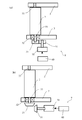
- FIG. 1 is a schematic side view illustrating an example of a configuration of a vertical wind power generation system according to Embodiment 1.
- FIG. 3 is a schematic diagram illustrating a configuration of a rotating unit of the vertical wind power generation system according to the first embodiment.
- 1 is a schematic diagram of a top view illustrating an example of a configuration of a vertical wind power generation system according to Embodiment 1.
- FIG. 1 is a schematic diagram of a top view illustrating an example of a configuration of a vertical wind power generation system according to Embodiment 1.
- FIG. 1 is a schematic diagram of a top view illustrating an example of a configuration of a vertical wind power generation system according to Embodiment 1.
- FIG. 1 is a schematic diagram of a top view illustrating an example of a configuration of a vertical wind power generation system according to Embodiment 1.
- FIG. 1 is a schematic diagram illustrating an example of a cross section of an airfoil of a vertical wind power generation system according to Embodiment 1.
- FIG. FIG. 3 is a schematic diagram illustrating a concentric arrangement configuration of vertical blades in the vertical wind power generation system according to the first embodiment.
- FIG. 3 is a schematic diagram illustrating a concentric arrangement configuration of vertical blades in the vertical wind power generation system according to the first embodiment.
- FIG. 3 is a schematic diagram illustrating a concentric arrangement configuration of vertical blades in the vertical wind power generation system according to the first embodiment. It is the figure which showed an example of the airfoil characteristic (lift characteristic, drag characteristic) in the airfoil cross section of the vertical wind power generation system which concerns on Embodiment 1.
- FIG. 1 It is the figure which showed the relationship between the circumferential speed ratio and relative speed of the vertical type wind power generation system which concerns on Embodiment 1.
- FIG. It is the figure which showed an example of the zone which defines the blade rotation angle of the vertical type wind power generation system which concerns on Embodiment 1, and a rotation angle table. It is the figure which showed an example of the rotation angle adjustment in the vertical type wind power generation system which concerns on Embodiment 1.
- FIG. It is the figure which showed an example of the rotation angle adjustment in the vertical type wind power generation system which concerns on Embodiment 1.
- FIG. It is the figure which showed an example of the rotation angle adjustment in the vertical type wind power generation system which concerns on Embodiment 1.
- FIG. It is the figure which showed an example of the rotation angle adjustment in the vertical type wind power generation system which concerns on Embodiment 1.
- FIG. 1 It is the figure which showed the relationship between the circumferential speed ratio and relative speed of the vertical type wind power generation system which concerns on Embodiment 1.
- FIG. It is
- FIG. 5 is a schematic diagram illustrating a configuration of a vertical hydroelectric power generation system according to Embodiment 2.
- FIG. 5 is a schematic diagram illustrating a configuration of a vertical hydroelectric power generation system according to Embodiment 2.
- FIG. 5 is a schematic diagram illustrating a configuration of a vertical hydroelectric power generation system according to Embodiment 2.
- FIG. 5 is a schematic diagram illustrating a configuration of a vertical hydroelectric power generation system according to Embodiment 2.
- FIG. 5 is a schematic diagram illustrating a configuration of a vertical hydroelectric power generation system according to Embodiment 2.
- FIG. FIG. 5 is a schematic diagram illustrating a configuration of a vertical blade of a vertical hydroelectric power generation system according to a second embodiment. It is the figure which showed the flow velocity distribution addition condition which concerns on Embodiment 2.
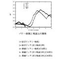
- FIG. It is the figure which showed the effect of the flow-velocity distribution addition in the high-speed area based on Embodiment 2.
- FIG. It is the figure which showed the effect of the flow-velocity distribution addition in the medium speed area based on Embodiment 2.
- FIG. It is the figure which showed the effect of the flow-velocity distribution addition in the low speed area based on Embodiment 2.
- FIG. 1 It is the figure which showed the improvement effect of the rotational torque in the high speed area based on Embodiment 2.
- FIG. It is the figure which showed the improvement effect of the rotational torque in the low speed area based on Embodiment 2.
- FIG. It is the schematic diagram which showed the structure of the vertical type hydroelectric power generation system which concerns on Embodiment 3.
- FIG. It is the figure which showed the optimal structure in the low peripheral speed ratio in the vertical type hydroelectric power generation system which concerns on Embodiment 4.
- FIG. It is the figure which showed the optimal structure in the low peripheral speed ratio in the vertical type hydroelectric power generation system which concerns on Embodiment 4.
- FIG. It is the figure which showed the optimal structure in the low peripheral speed ratio in the vertical type hydroelectric power generation system which concerns on Embodiment 4.
- FIG. It is the figure which showed the optimal structure in the low peripheral speed ratio in the vertical type hydroelectric power generation system which concerns on Embodiment 4.
- FIG. It is the figure which showed the optimal structure in the low peripheral speed ratio
- FIG. It is the figure which showed the optimal structure in the low peripheral speed ratio in the vertical type hydroelectric power generation system which concerns on Embodiment 4.
- FIG. It is the figure which showed the effect of the flow-velocity distribution of the vertical type hydroelectric power generation system which concerns on Embodiment 4.
- the blade characteristics of the blades such as lift and drag, blade size, The number of blades, the solidity, and the relative angle of the blades are important components, and a blade configuration that takes all of them into consideration is essential. If this point is not taken into consideration, the start-up characteristics and the power generation efficiency cannot be greatly improved, but no consideration is given to such a configuration.
- the inventors have come up with the idea that a combination of adjusting the angle of attack of the blade, multiple concentric blade configurations, adjusting the inflow energy distribution, etc. may have a significant effect on the starting characteristics and power generation efficiency. Therefore, the present inventor obtained the following knowledge as a result of repeated studies on this problem.
- the configuration of the concentric vertical blades increases the solidity or increases the angle of attack according to the straight blades arranged from the outer periphery to the inner periphery. Is required to have a configuration corresponding to a low peripheral speed ratio.
- the angle of attack the present inventors have found that the angle of attack at which the maximum output is output when the peripheral speed ratio is small varies greatly with respect to the angle of attack at which the maximum output is output when the peripheral speed ratio is large at each blade rotation angle. Therefore, even if the vertical wings are arranged concentrically, solidity setting and angle-of-attack control are indispensable in order to greatly improve the start-up characteristics, the characteristics during light winds, and the power generation efficiency at the medium speed level. I came up with an idea.
- the blade type of the vertical blade airfoil characteristics indicating the relationship between lift and drag, angle of attack and Reynolds number, the configuration conditions such as diameter and solidity, the influence of operating conditions such as the rotational speed of the vertical blade,
- the relative angle value at which the rotational energy conversion efficiency is maximized according to environmental changes such as wind speed and direction is examined in detail, and the rotational energy conversion efficiency changes regularly and greatly under each configuration, operating condition, and environmental condition. I found that there is a relative angle. In particular, it has been found that there is a law that the higher the solidity, the lower the rotational speed at which the maximum efficiency is obtained, and the lower the rotational speed, the greater the change in the relative angle at which the maximum efficiency is obtained in one rotation.
- a vertical wind power generation system includes a vertical blade composed of a plurality of straight blades arranged concentrically on at least two rows of circumferences on the inner circumferential side and the outer circumferential side.
- An arm that holds the vertical blade or the straight blade, a shaft unit that is fixed to the arm and supports the rotation of the arm, and interlocks with the shaft unit to convert rotational energy of the vertical blade into electrical energy.
- a generator a pole that holds the vertical blade, the arm, and the shaft unit; a shaft unit holding portion that includes a bearing and that pivotally supports the shaft unit on the pole; Generates the maximum output of the vertical blades arranged circumferentially on the inner side with respect to the vertical blades arranged on the circumference. Rotational speed or circumferential speed ratio is stepwise smaller configuration.
- the straight blades of the vertical blades arranged concentrically have a blade configuration that generates maximum output at a low rotational speed from the outer periphery to the inner periphery, and the angle of attack.
- the flow velocity energy of the wind passing through the inside without being converted into the rotational energy of the vertical blade at the outer periphery can be converted again into the rotational energy, and not only at the time of light winds and low wind speeds, but about 6 m / s
- the power generation efficiency of the vertical wind power generation system can be greatly improved even at high speed levels and strong wind speed levels of about 12 m / s.
- the number of rotations at which the maximum output is output increases as the wind speed increases, and the number of rotations at which the maximum output increases as the solidity increases.
- each straight blade attached to the same vertical blade has a lower circumferential speed ratio as it goes to the inner circumference. Therefore, by setting the blade configuration or angle of attack or relative angle to generate maximum output at a low rotational speed from the outer peripheral part to the inner peripheral part of the straight blades of the vertical blades arranged concentrically, the startup or low It is possible to efficiently convert the energy of the air flow that passes through the vertical blade at the outer peripheral portion and flows into the central portion of the vertical blade into rotational energy again at the rotational speed, and has excellent start-up characteristics. Thus, it is possible to realize a vertical wind power generation system or a vertical hydroelectric power generation system that greatly improves the power generation efficiency at a low rotation speed and during a light wind of 3 m / s or less.
- the vertical wind power generation system according to the second aspect of the present invention is the vertical wind power generation system according to the first aspect, wherein the vertical blades are arranged on the inner circumference.
- the solidity of the straight wing is configured to be increased stepwise with respect to the solidity of the straight wing disposed on the outer circumference.
- the solidity of the straight blades of the vertical blades arranged concentrically is increased stepwise from the outer peripheral portion toward the inner peripheral portion, so that the vertical blades are arranged as they are arranged on the inner peripheral side.
- the configuration of the straight blades corresponding to the increase in the peripheral speed ratio of the blade, and the blade configuration with the solidity corresponding to the peripheral speed ratio efficiently improves the rotational energy conversion efficiency and maximizes the power generation efficiency
- the vertical blade can be realized.
- the vertical wind power generation system according to the third aspect of the present invention is the configuration of the vertical wind power generation system according to the first or second aspect with respect to the wind speed and the peripheral speed that is the rotational speed of the vertical blade.
- a so-called angle of attack is defined which is an angle formed by a relative wind speed or relative flow velocity combined with the head wind speed and a chord as a line segment connecting the leading edge and the trailing edge of the straight blade.
- the relative angle is an angle between the chord and the arm, or the chord and the straight wing for the purpose of changing the relative angle in order to obtain an angle of attack that increases the tangential rotational force.
- Rotating means for independently rotating the relative angles of the straight blades in the plane of rotation of the vertical blade as an angle with the tangential direction at the holding position.
- a rotation angle control device for controlling the relative angle by the rotation means, and a blade rotation angle of the vertical blade or each of the straight blades from a reference angle in a plane coordinate system based on the rotation center of the vertical blade.
- the lift coefficient and drag coefficient representing the airfoil characteristics are shown in relation to the angle of attack, and it is possible to accurately incorporate the airfoil characteristics that are the basis of calculation in the rotation angle table. Therefore, it is possible to derive a vertical wind power generation system with excellent rotational energy conversion efficiency and power generation efficiency.
- the rotation angle table is the airfoil characteristics consisting of the wind speed, the blade diameter of the vertical blade, the airfoil wind speed or Reynolds number and lift characteristics and drag against the angle of attack, the rotation speed or peripheral speed ratio, the chord length From all or one or more of the blade chord length, the blade length that is the total length of the vertical blade, the solidity calculated from the number of straight blades and the blade diameter of the vertical blade, and the blade rotation angle It shows the relationship between the calculated blade rotation angle and relative angle.
- This configuration is required to improve rotational energy conversion efficiency, such as wind speed or Reynolds number, blade diameter of vertical blade, rotation speed or peripheral speed ratio, solidity, blade rotation angle, airfoil and its airfoil characteristics. Considering all the factors, it is possible to calculate an optimum and more accurate relative angle and rotation angle table, and it is possible to realize a vertical wind power generation system with excellent rotational energy conversion efficiency and power generation efficiency.
- the vertical wind power generation system includes a plurality of double wind or triple concentric circles arranged in the vertical wind power generation system according to the first to third aspects.
- the straight blade having the straight blade only the straight blade other than the innermost or outermost periphery controls the relative angle of the straight blade according to the vertical blade rotation angle.
- the peripheral speed ratio becomes faster as it is positioned on the outer periphery.
- the effect of the influence of the adjustment of the relative angle on the power generation efficiency tends to increase as the relative angle has a smaller peripheral speed ratio (rotation speed).
- a vertical wind power generation system is the vertical wind power generation system according to the first to fourth aspects, wherein the vertical blade includes a plurality of straight blades, A vertical blade or an arm that holds the straight blade, a shaft unit that is fixed to the arm and supports the rotation of the arm, and a generator that operates in conjunction with the shaft unit and converts rotational energy of the vertical blade into electrical energy.
- a vertical wind power generation system or a vertical wind power generation system that can concentrate the flow velocity on the blade rotation angle or zone that has a preset angle range with high rotational force in the direction, has excellent rotational energy conversion efficiency and power generation efficiency, and has a large amount of power generation Type hydroelectric power generation system can be realized.
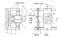
- the flow velocity distribution includes air or water to the vertical blade.
- the flow velocity in the region of the substantially central portion that is 30% to 85% of the diameter of the vertical blade or the flow velocity in the region of 120 to 250 degrees in the blade rotation angle is increased. It is set as the structure which reduces the flow velocity of division areas other than.
- the water flowing near the blade rotation angle where the tangential rotational force generated by the vertical blade is the highest in the flow velocity energy of the air flowing into the vertical blade or the water or air flowing into the water.
- the blade rotation angle at which the power generation efficiency is highest at the blade rotation angle of the vertical blade, or the blade rotation angle at which the rotational force in the tangential direction due to lift and effectiveness is high. It is possible to concentrate the flow velocity in the vicinity, and it is possible to realize a vertical wind power generation system or a vertical hydropower generation system that is excellent in rotational energy conversion efficiency and power generation efficiency and has a large amount of power generation.
- the vertical wind power generation system detects the flow velocity of air or water to the vertical blade in the configuration of the vertical wind power generation system according to the first to sixth aspects.
- a flow velocity detecting means and / or an inflow angle detecting device for detecting an inflow angle wherein the flow velocity distribution adding device is constituted by a plurality of flow velocity control means, and the flow velocity of air or water and the inflow angle to the vertical blade Accordingly, the flow velocity distribution pattern is variable.
- the angles of the plurality of control plates are adjusted based on information from the inflow angle detection device and the inflow velocity detection device, and a flow velocity distribution is added to the inflow surface orthogonal to the inflow surface of the vertical blade. By doing so, it is possible to form the flow velocity distribution with the highest power generation efficiency even at various flow velocities and inflow angles.
- the vertical wind power generation system is the configuration of the vertical wind power generation system according to the first to seventh aspects, wherein the flow velocity distribution includes air or water to the vertical blades.
- the flow velocity distribution is the flow rate, flow velocity, rotation speed or peripheral speed ratio of the vertical blade in the rectangular cross section orthogonal to the air or water inflow surface to the vertical blade.
- the flow velocity of the region of an arbitrary cross section which is 30% to 85% of the diameter of the vertical blade and is not limited to the substantially central portion is increased, The flow rate is reduced.
- the flow velocity can be concentrated in the vicinity of the blade rotation angle where the power generation efficiency is high or the blade rotation angle where the rotational force in the tangential direction is high due to lift and effectiveness, and the rotational energy conversion efficiency and power generation efficiency are excellent, and the amount of power generation It is possible to realize a vertical wind power generation system or a vertical hydroelectric power generation system with a large amount of water.
- the flow velocity control unit operates with respect to the flow velocity control device.
- the flow velocity distribution is made variable by the moving or sliding flux distribution control unit.
- various flow velocity distributions can be formed with a relatively simple configuration, and in addition, it is possible to form a highly accurate flow velocity distribution in a short time. It is possible to realize a distributed addition device, reduce the equipment cost, and realize a vertical wind power generation system or vertical hydroelectric power generation system that has excellent rotational energy conversion efficiency and power generation efficiency, high power generation and high investment recovery efficiency. It becomes possible.
- the vertical wind power generation system according to the tenth aspect of the present invention is the vertical wind power generation system according to the first to ninth aspects, wherein the relative angle and the flow velocity distribution of the straight blades are expressed as The flow rate, the inflow angle, and the peripheral speed ratio are variable according to one or more conditions.
- the maximum power generation amount can always be generated with respect to inflow conditions such as flow velocity and inflow angle to the vertical blade, inflow state change, temperature change, and peripheral speed ratio.
- inflow conditions such as flow velocity and inflow angle to the vertical blade, inflow state change, temperature change, and peripheral speed ratio.
- the vertical wind power generation system according to the eleventh aspect of the present invention is the configuration of the vertical wind power generation system according to the first to tenth aspects, wherein the flow velocity distribution adding device causes the flow direction of air or water.
- the inflow area of air or water flowing into the vertical blade is made larger than the projected area of the vertical blade in FIG.
- a vertical wind power generation system is the vertical wind power generation system according to any of the first to eleventh aspects, wherein air or water is supplied to the vertical type by the flow velocity distribution adding device.
- the inflow area that flows into the blade is configured to be variable according to the flow rate of air or water or the flow rate of water.
- the flow rate of air or water flowing into the vertical blades can be freely adjusted according to the maximum wind speed (maximum flow velocity), maximum flow rate conditions, generator capacity, river width and depth, etc.
- maximum wind speed maximum flow velocity
- generator capacity maximum flow rate conditions
- generator capacity generator capacity
- river width and depth etc.
- the vertical blades and generators with a large area can realize a vertical wind power generation system or a vertical hydropower generation system with a larger power generation output.
- the vertical wind power generation system according to the thirteenth aspect of the present invention is a configuration of the vertical wind power generation system according to the first to twelfth aspects, wherein a plurality of double wind or triple concentric circles are arranged.
- the relative angle of the straight blade is controlled to an angle at which the rotational torque is reduced according to the rotation angle of the vertical blade in all or only the straight blade on a specific concentric circle. It is configured.
- the relative angle is controlled to reduce the power generation efficiency, or the flow velocity distribution adding device flows into the vertical blade.
- the flow velocity or the flow rate is reduced.
- Type wind power generation system or vertical hydroelectric power generation system can be realized.
- a vertical wind power generation system has a relative angle adjustment mode in the configuration of the vertical wind power generation system according to the first to thirteenth aspects, and has the flow velocity and the rotation speed.
- the angle adjustment of the relative angle in the linear blade according to the peripheral speed ratio and the blade rotation angle is performed, and the optimum fixed angle of the relative angle or the rotation angle table that maximizes the power generation efficiency is created. .
- the straight line is set at the relative angle at which the power generation efficiency becomes highest or the tangential rotational torque becomes maximum for each blade rotation angle range (zone) set in advance in the rotation surface of the vertical blade.
- the relative angle based on the rotation angle table set or updated in the rotation angle table or the relative angle adjustment mode set in advance.
- the rotation angle table is not used, and the constant relative angle (fixed angle) is always used regardless of the blade rotation angle of the vertical blade.
- the relative angle may be used.
- the relative angle of the straight blades is adjusted one by one or at the same time, and the power generation efficiency, the tangential rotational torque, and the power generation amount are confirmed, and the relative angle (attack angle of fixed angle) is confirmed. Will be set.
- the vertical wind power generation system is the configuration of the vertical wind power generation system according to the first to fourteenth aspects, wherein the flow velocity detection means of wind or water and the vertical blade In the relative angle adjustment mode, the relative angle adjustment is performed for each straight blade, and the wind speed or the flow velocity, the rotation speed or the peripheral speed ratio, the power generation efficiency or A relationship of output characteristics is acquired, and each of the straight blades is automatically adjusted to the relative angle at which the maximum output is obtained.
- the assembly of the individual straight blades of the vertical blade is further performed by adjusting the relative angle with high accuracy. It is possible to correct variations, errors, component accuracy, aging deterioration, and the like, and it is possible to realize a vertical wind power generation system and a vertical vertical power generation system that have excellent reliability and large power generation amount and power generation efficiency.
- the vertical wind power generation system has an output inspection mode in the configuration of the vertical wind power generation system according to the first to fifteenth aspects, and stores the previous power generation stored. Regularly compare the output characteristics such as efficiency or power generation amount to grasp the power generation state, and if the change amount of the preset output characteristics is exceeded, execute the relative angle adjustment mode to perform the relative angle periodically. It is configured to perform maintenance.
- the straight blades, the vertical blades and the vertical wind power generation system are deteriorated over time, the arms and the shaft unit, the relative angles, etc. Faults can be detected with high accuracy, and it is possible to realize a vertical wind power generation system and a vertical hydroelectric power generation system that are highly reliable by regular maintenance and have a large amount of power generation and efficiency.
- the vertical wind power generation system according to the seventeenth aspect of the present invention is the configuration of the vertical wind power generation system according to the first to sixteenth aspects, wherein air or water that has flowed into the vertical blades into the frame.
- the flow velocity acceleration mechanism for increasing the flow velocity is provided.
- the vertical wind power generation system having a large power generation amount and power generation efficiency or A vertical hydroelectric power generation system can be realized.
- the vertical wind power generation system according to the eighteenth aspect of the present invention is the vertical wind power generation system according to the first to seventeenth aspects, wherein the flow velocity acceleration mechanism is a flow path through which air or water passes. The width is narrowed.
- the vertical velocity power generation system and the vertical type that can realize the flow velocity acceleration mechanism with a relatively simple configuration and at a low cost, have large power generation amount and power generation efficiency, and are excellent in economic efficiency due to reduction in equipment costs.
- a hydroelectric power generation system can be realized.
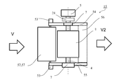
- the vertical wind power generation system according to the nineteenth aspect of the present invention is the vertical wind power generation system according to the first to eighteenth aspects, wherein the vertical blades are arranged in two independent spaces of the frame. It is mounted on the machine, and the direction of the leading edge and the trailing edge and the relative angle of the straight blades constituting the vertical blade are set so that the respective rotation directions are reversed.
- the vertical wind power generation system according to the twentieth aspect of the present invention is generated from lift and drag with the rotation of the vertical blade in the configuration of the vertical wind power generation system according to the first to nineteenth aspects.
- the vertical blades are arranged so that the forces acting on the frame by the generated force in the X direction and the generated force in the Y direction on the XY plane in the horizontal plane are offset and minimized.
- the vertical wind power generation system according to the twenty-first aspect of the present invention is the vertical wind power generation system according to the first to twentieth aspects, wherein the flow velocity of air or water flowing into the vertical blades or When the flow rate is larger than necessary, the relative angle is controlled to reduce the power generation efficiency, or the flow velocity or the flow rate flowing into the vertical blade is reduced by the flow velocity distribution adding device.
- FIGS. 1 to 4 are schematic views showing an example of the configuration of the vertical wind power generation system according to Embodiment 1.
- FIG. 1 the structure when the vertical wind power generation system which concerns on Embodiment 1 is seen from the side part is shown typically.
- FIG. 2 is a schematic diagram showing the configuration of the straight blade 2 and its rotating means 9 mounted on the wind power generation system according to the first embodiment.
- FIG. 3 schematically shows a configuration when the wind power generation system according to Embodiment 1 is viewed from above.
- the vertical wind power generation system 15 includes a vertical blade 1, a straight blade 2, an arm 3, a shaft unit 4, a generator 5, a pole 6, a shaft unit holding unit 7, Relative angle 8, rotation means 9, rotation angle control device 10, planar coordinate system 11, reference angle 12, blade rotation angle 13, rotation angle table 14, vertical wind power generation system 15, wind speed 16, wind speed detection means 17, rotation Number detection means 18, wind direction detection means 19, rotation torque 20 (shown in FIG. 11), rotation suppression torque variable means 21 (shown in FIG. 11), generator controller (rotation speed control means) 22 (shown in FIG. 11), A power controller 23 (shown in FIG. 11), a coupling portion 24, a vertical blade mounting portion 27, and a wind direction 28, which is an angle shown, are configured.
- the vertical blade 1 is composed of a plurality of straight blades 2 arranged concentrically, and is held rotatably by an arm 3.
- the shaft unit 4 fixes and holds the arm 3 and supports the rotation of the arm.
- the shaft unit 4 is coupled (or integrated) with the rotating portion (rotor, shaft, etc.) of the generator 5 that converts the rotational energy of the vertical blade 1 into electric energy, and interlocks with it. Convert to energy.
- the shaft unit 4 and the rotating portion of the generator 5 may be coupled via a coupling portion 24 (not shown in detail).
- the coupling portion 24 is a coupling, a gear, a speed increaser, a speed reducer, or the like. Or any combination thereof.
- the rotational speed-output characteristic of the vertical blade 1 and the rotational speed-output characteristic of the generator 5 can be matched by the speed increasing ratio or the speed reducing ratio of the coupling portion 24.
- the pole 6 holds the shaft unit 4 by fixing the vertical blade 1 and the arm 3 by a shaft unit holding part 7 constituted by a bearing and a holding part (details are not shown).
- the pole 6 is held in a rotatable state.
- one or a plurality of wind speed detecting means 17 detects the wind speed around the vertical blade 1
- the rotational speed detecting means 18 detects the rotational speed of the vertical blade 1
- the wind direction detecting means 19 is the vertical blade 19.
- the wind direction 28 (angle) with respect to the reference angle 12 centering on the rotation center O of the plane coordinate system 11 of the wind flowing in is detected.
- the straight blade 2 is rotatably held by the arm 3 by the turning means 9.
- the rotation means 9 uses a rotation shaft portion 33, a stepping motor, a DC motor, an ultrasonic motor, a drive source 30 such as a piezoelectric element, a power transmission portion 31 composed of a gear, a coupling, a shaft, a bearing, and the like.
- the power supply 60 such as a battery that supplies power to the shaft support 32 and the drive source 30 is configured, and the straight blade 2 is held with respect to the arm 3 in a rotational state of ⁇ 180 degrees at the maximum.
- the shaft support portion 32 is not limited to a bearing, and may be a known shaft support member having slidability.
- the power transmission part 31 may be through various gears and couplings, or may be configured such that the drive source 30 and the rotation shaft part 33 are directly coupled.
- the vertical wind power generation system 15 can be reduced in size, and the influence of wind and rain and ultraviolet rays can be suppressed.
- the vertical wind power generation system 15 with excellent durability can be realized.
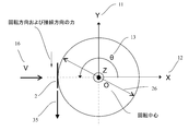
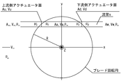
- FIG. 3A shows a reference angle 12 (0 degree) in the plane coordinate system 11 (X axis, Y axis, Z axis, origin O), two types of blade rotation angles 13 ( ⁇ ) of the vertical blade 1 (straight blade 2), A blade diameter 26 which is the diameter of the vertical blade 1, a mounting portion 27 between the arm 3 and the straight blade 2, and two types of relative angles 8, a wind speed 16, a wind direction 28, and a blade diameter 26 are shown.
- the straight blade 2 is held in a rotatable state at an attachment angle of a relative angle 8 at the attachment portion 27 relative to the arm 3.
- FIG. 3B and 3C are diagrams showing the relationship between the blade rotation angle 13 and the angle of attack 38.
- the straight blade 2 is at a position of about 180 degrees for simplicity of explanation, and the rotational speed of the blade diameter 26 (outer periphery) corresponding to the rotational speed of the vertical blade 1 under the condition of the wind speed 16 (V).
- V wind speed
- the circumferential speed 35 is expressed in units of m / s.
- FIG. 3C is a diagram showing the angle of attack 38 in FIG. 3B, and the angle of attack 38 used when representing the airfoil characteristics is obtained as follows. That is, the so-called relative wind speed 37 that is a combination of the wind speed 16 and the circumferential speed 36 with respect to the circumferential speed 35 that is the rotational speed at the blade diameter 26 (outer periphery) of the vertical blade 1, and the chord 25 of the straight blade 2. It is an angle to make. As a basic mechanism of the present invention, the relative angle 8 is changed in order to obtain an angle of attack 38 that increases the rotational force (rotational torque) in the tangential direction.
- FIG. 4 is a schematic diagram of a cross-sectional shape of the straight blade 2 mounted on the vertical wind power generation system according to the first embodiment.
- FIG. 4A is a diagram of the straight blade 2 mounted on the wind power generation system according to the first embodiment.
- FIG. 4B is a view showing an example of a so-called asymmetric wing in a cross-sectional shape, and
- FIG. 4B is a view showing an example of a so-called asymmetric wing.
- a line segment connecting the leading edge and the trailing edge of the straight blade 2 is a chord 25, and the length of the chord 25 is a chord length 29.
- FIG. 4C shows an angle of attack 38 that is an angle between the relative wind speed 37 and the chord 25 when rotated around the attachment position 27 in the airfoil cross section shown in FIGS. 4A and 4B. And the lift force 40 and the drag force 41 generated on the surface of the airfoil cross section. Wind speed 16, chord 25, mounting portion 27, blade rotation angle 13, relative angle 8, relative wind speed 37, angle of attack 38, pitch angle 39, lift 40, drag 41, rotation torque 42 by lift 40, rotation suppression by drag 41
- FIG. 6 is a diagram showing a relationship of torque (minus torque) 43;
- the relative angle 8 is a diagram in the case of the angle formed by the arm 3 and the chord 25. At this time, when the relative angle 8 is the angle between the chord 25 and the tangential direction at the attachment position 27, the pitch angle 39 becomes the relative angle 8.
- the pitch angle 39 can be expressed as (relative angle 8) -90 degrees.
- the rotation inhibition torque 43 by the drag 41 may be a positive rotation torque when the peripheral speed ratio is 1 or less and the blade rotation angle 13 is between 180 degrees and 360 degrees. Therefore, in order to increase the rotational energy conversion efficiency Cp in the region where the peripheral speed ratio is 1 or more, it is necessary to increase the rotational torque 42 by the lift force 40 and decrease the rotation suppression torque 43 by the drag force 41.
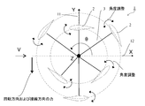
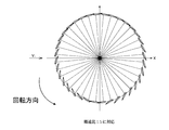
- FIG. 5A schematically shows a configuration when the wind power generation system 15 is viewed from the upper surface, and is a schematic diagram partially viewing the vertical blade 1 from the upper surface.
- the vertical blade 1 is composed of a plurality of straight blades 2 arranged concentrically, and is held rotatably by an arm 3 and a shaft unit 4. Further, the plurality of straight blades 2 arranged concentrically are respectively held by the same arm 3, and according to the blade rotation angle 13, the rotation speed (or peripheral speed ratio) of the vertical blade 1, the wind speed 16, and the like.
- the relative angle 8 can be adjusted by the rotating means 9.
- the circumferential speed ratio of the straight blades 2 arranged on the same arm 3 inevitably becomes smaller on the inner peripheral side regardless of the rotation speed of the vertical blade 1. Therefore, the solidity of the straight blade 2 located on the same concentric circle on the inner peripheral side (ratio of the circumference length and the chord length 29 ⁇ the number of blades at the blade diameter 26) is equal to that of the straight blade 2 located on the inner periphery side. It is set as the structure which enlarges with respect to the direction of the linear blade 2 located in the outer peripheral side.
- the rotational energy conversion efficiency can be increased at a relatively low rotational speed, and conversely, the rotational energy conversion efficiency can be increased at a relatively high rotational speed by decreasing the solidity. . Therefore, by maximizing the maximum output or rotational energy conversion efficiency under the given circumferential speed ratio condition, in order to always demonstrate the maximum power generation efficiency in a wide range of environmental conditions from the starting characteristics to the high wind speed, Increasing the solidity of the straight blade 2 is an essential constituent condition of the vertical blade 1.
- the solidity and inner The solidity of the circumferential straight wing 2 will be determined.
- the peripheral speed ratio that maximizes the rotational energy conversion efficiency Shifts to the smaller By increasing the solidity of the straight blades 2 (linear blades 2 having the same rotation speed and a smaller peripheral speed ratio) located on the same concentric circle on the inner peripheral side, the peripheral speed ratio that maximizes the rotational energy conversion efficiency Shifts to the smaller.
- the rotational energy conversion efficiency is improved when the wind speed is relatively low and when the wind speed is low. Accordingly, it is possible to greatly improve the rotational torque at the low rotational speed, at the start-up, and at the fractional speed, and the start-up characteristics of the vertical blade 1, the power generation efficiency at the low speed, the power generation efficiency at the low wind speed and the power generation amount. Can be greatly improved.
- the straight blades 2 positioned on the inner circumference side and the straight blades 2 positioned on the outer circumference side may be different from each other, or may have different relative angle 8 fixed values.
- the relative angle 8 of each straight blade 2 may be configured to adjust the angle based on the rotation angle table 14.
- a straight line corresponding to the blade rotation angle 13 is obtained by the rotation means 9 and the rotation angle control device 10 based on the rotation angle table 14 having a relative angle 8 calculated from the blade rotation angle 13.
- the relative angle 8 is set so that the rotational torque due to the drag is improved as much as possible during startup, and the relative angle 8 is set so that the rotational torque due to the lift is increased during normal rotation, or the relative angle is increased so that the lift-drag ratio is increased. It is desirable to set to 8.
- the rotation angle table 14 is configured to use values calculated in advance or values calculated in part or all in real time.
- the rotation angle table 14 is calculated in advance, stored in a memory, and taken out when necessary, so that calculation time is not required when adjusting the relative angle 8, and energy and time required for calculation each time are not required.
- a vertical wind power generation system with no control time delay and high energy efficiency can be realized.
- a system such as a memory for storing the rotation angle table 14 is not required, so that a relatively low cost and small vertical wind power generation system can be realized.
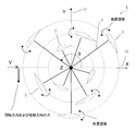
- the linear blade 2 positioned on the outer peripheral side concentric circle and the straight blade 2 positioned on the inner peripheral side concentric circle are attached to different arms 3 and arranged at different angles.
- the efficiency of conversion into rotational energy is low during startup, light winds, and low wind speeds, and the wind or flux that passes without being converted into rotational energy is increased by the straight blades 2 arranged on the outer periphery of the concentric circle. Therefore, with this configuration, the wind or flux that has passed without being converted into rotational energy by the straight blades 2 positioned on the concentric circle on the outer peripheral side is again returned by the straight blades 2 positioned on the concentric circle on the inner peripheral side. It is converted into rotational energy, and it becomes possible to further improve the rotational energy conversion efficiency at the time of start-up, light winds, and low wind speeds.
- FIG. 6 is a diagram showing the airfoil characteristics in the cross-sectional shape of the straight blade 2 mounted on the wind power generation system according to the first embodiment.
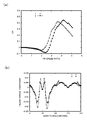
- FIG. 6A shows an example of the relationship between the angle of attack 38 (ATTACK ANGLE) and the drag coefficient (CD) (reference diagram for a specific wind speed or Reynolds number), and FIG. 6B shows the angle of attack 38 (ATTACK ANGLE). And the lift coefficient (CL).
- ATTACK ANGLE the angle of attack 38
- CD drag coefficient
- CL lift coefficient
- both the drag coefficient and the lift coefficient can be converted to force (N / m) by multiplying the coefficient by 1/2 ( ⁇ CV 2 ).
- ⁇ is the air density (kg / m 3 )
- C is the chord length 29 (m)
- V is the wind speed (m / s).
- FIG. 7 shows the relationship between the circumferential speed ratio ⁇ , the wind speed 16, the circumferential speed 36, the relative speed 37, and the blade rotation angle ( ⁇ ) 13 in the straight blade 2 mounted in the wind power generation system according to the first embodiment. It is a schematic diagram.
- FIG. 7A and 7B show the relationship between the blade rotation angle 13 and the relative speed 37 when the peripheral speed ratio ⁇ is 1 or less and when the peripheral speed ratio exceeds 1.
- FIG. 7A and 7B show the relationship between the blade rotation angle 13 and the relative speed 37 when the peripheral speed ratio ⁇ is 1 or less and when the peripheral speed ratio exceeds 1.
- FIG. 7 (c) and 7 (d) are diagrams showing the relationship between the peripheral speed ratio and the angle of attack 38.
- FIG. When the pitch angle 39 is fixed at 0 degree, the angle of attack 38 is 0 to 360 degrees in the region where the circumferential speed ratio is 1 or less, but when the circumferential speed ratio exceeds 1, the angle of attack 8 is significantly reduced.
- the relative wind speed 37 hits from the airfoil side of the airfoil on the downstream side (0 ⁇ ⁇ ⁇ 90 degrees, 270 degrees ⁇ ⁇ ⁇ 360 degrees) in the plane coordinate system 11 of the vertical blade 1. Become. Therefore, it can be seen that the value of the angle of attack 38 with respect to the blade rotation angle 13 varies greatly depending on the size of the peripheral speed ratio.
- FIG. 8 is a diagram showing an example of the rotation angle table 14 mounted on the vertical wind power generation system 15 according to the first embodiment.
- FIG. 8A is a reference diagram in which the blade rotation angle 13 is divided. In this case, 360 degrees is divided into eight equal parts, and the optimum relative angle 8 is calculated for each zone.
- FIG. 8B is a diagram showing an example of the rotation angle table 14 in which the relative angle 8 is calculated by increasing the number of zone divisions, and the pitch angle 39 at each peripheral speed ratio when the wind speed 16 is 12 m / s.
- An example of the rotation angle table 14 is shown.
- the rotation angle table 14 shows the relationship between the attack angle 38, the relative angle 8 or the pitch angle 39, the blade rotation angle 13, the circumferential speed ratio, and the wind speed 16.
- the horizontal axis represents the blade rotation angle 13
- the vertical axis represents the relative angle 8, the angle of attack 38 or the pitch angle 39
- a plurality of pieces of information for each peripheral speed ratio and / or wind speed were converted into mapping data. It shows data information such as graphs and tables.
- Pitch angle 39 (relative angle 8) at which the rotational energy conversion efficiency (Cp) is maximum in the state of the peripheral speed ratio 0.5 where the rotational speed is relatively low, compared to the state of the peripheral speed ratio 3 where the rotational speed is relatively high.
- the value of must be changed greatly.
- the relative angle 8, the angle of attack 38 and the pitch angle 39 that maximize Cp vary greatly depending on the peripheral speed ratio, and the angle is smaller when the peripheral speed ratio is smaller than when the peripheral speed ratio is large. The amount of change increases.
- the wind speed is assumed to be in the range of 0 m / s to a maximum of 100 m / s, and the relative angle 8 is set to ⁇ 180 degrees with an adjustment range of 90 degrees.
- the pitch angle 39 at which Cp is maximum varies greatly from +80 degrees to ⁇ 80 degrees, but defines an energy conversion efficiency change amount ( ⁇ Cp). Then, considering the energy improvement effect by ⁇ Cp and the energy required for rotation, if there is a merit, the pitch angle 39 may be adjusted, and if the improvement effect of ⁇ Cp is low, the change of the pitch angle 39 A rotation angle table 14 that reduces the amount may be used.
- the rotation angle table 14 is calculated by calculating the wind speed 16 of the wind flowing into the vertical blade 1 in the plane coordinate system 11, the blade diameter 26 of the vertical blade 1, the wind speed or Reynolds number of the airfoil, and the lift characteristics and drag force against the angle of attack 38. Calculated from the airfoil characteristics (see FIG.
- a precise rotation angle table 14 can be created.
- the blade length 34 is substituted (calculated) with a reference length, the rotation angle table 14 can be calculated, and the entire blade is calculated.
- the blade length 34 is not essential for the calculation of the rotation angle table 14.
- the rotation angle table 14 may be calculated in advance or may be configured to calculate in real time. In the case of calculating in advance, at least the relationship between the angle of attack 38, the relative angle 8 or the pitch angle 39, the blade rotation angle 13, the peripheral speed ratio and the wind speed 16 is provided in the form of a data set, and the wind speed detecting means 17 is provided.
- the attack angle 38, the relative angle 8 or the pitch angle 39 corresponding to the blade rotation angle 13 can be read with reference to the detection results by the rotation speed detection means 18 and the wind direction detection means 19.
- the rotation angle table 14 is stored in the storage means of the computer, and reading is realized by inputting the detection results of the detection means 17, 18, 19 to the computer.
- the blade diameter 26, the solidity value, and the like are provided in advance, and the detection results obtained by the wind speed detection means 17, the rotation speed detection means 18, and the wind direction detection means 19 are calculated by computer calculation means.
- the angle of attack 38, the relative angle 8 or the pitch angle 39 according to the blade rotation angle 13 can be calculated.
- FIGS. 9A to 9C show the relative angle 8 or the pitch angle in the peripheral speed ratio 0.5 (FIG. 9A), the peripheral speed ratio 1.5 (FIG. 9B), and the peripheral speed ratio 3 (FIG. 9C) in FIG.
- This is an example illustrating 39 rotation angle tables 14.
- the wind direction 28 is parallel to the x axis, and specific values are used for the wind speed 16, blade diameter 26, solidity, airfoil shape, and blade characteristics, but detailed numerical values are not presented.
- the calculation of the rotation angle table 14 is a so-called multiflow tube model that calculates the blade element momentum theory in a number of divided regions in the calculation of Cp, and a multiflow tube that performs calculations upstream and downstream of the wind flow, respectively. This was performed by the double actuator method.
- the blade crossing the upstream actuator is subjected to a flow of the combined relative speed W of the circumferential speed V r due to the blade rotation and the wind speed V u of the upstream actuator of Formula 12.
- the force acting on the blade placed in the uniform flow having the relative velocity W acts on the blade at the upstream actuator position.
- the force F B acting on the blade at the upstream actuator position is determined by the angle of attack at the Reynolds number, lift L and angle of attack when an airfoil having a blade cross-sectional shape is placed in a uniform flow of the relative velocity. It is calculated from data prepared in advance for the relationship of drag D.
- blade acting force F B is a function of the wind speed V u in the upstream-side actuator.
- the blade acting force F B is a function F B of a u (a u). Equation for a u obtained by equalizing the x-direction component F Bx (a u ) and Equation 12
- the blade acting force F B is obtained from the solution of
- the rotary circular tangential component of the blade acting force F B is the blade rotational driving force.
- the downstream actuator is processed in the same manner as the upstream actuator by setting the flow tube inlet condition as the wind speed V a in the wind turbine and the flow tube cross-sectional area A a, and the blade rotational driving force on the downstream side is calculated. . If the above processing is performed on each flow tube, the blade rotation driving force and torque for each flow tube are obtained, and the output (P) of the entire wind turbine is calculated from the sum.
- Cp P / (1 / 2 ⁇ AV 3 )
- FIGS. 9A to 9C show an example of the rotation angle control of the relative angle 8 or the pitch angle 39 of only the straight blades 2 arranged on the same circumference.
- This rotation angle control is performed by a plurality of concentric circles shown in FIGS. 5A to 5C.
- the vertical wind power generation system 15 or the vertical hydroelectric power generation system having further excellent power generation efficiency, rotational energy conversion efficiency, and start-up characteristics can be obtained by performing the vertical blades 1 arranged in the shape of the straight blades 2 on the concentric circles. realizable.
- FIG. 10 shows a process of deriving the relative angle 8 that maximizes Cp.
- FIG. 10 (a) shows the process of calculating the relative angle 8 (or angle of attack 38, pitch angle 39) at which Cp is maximum for each zone. The relative angle 8 at which Cp is maximum in each zone is shown. It is an example which showed energy conversion efficiency improvement amount ((DELTA) Cp) at the time of calculating and changing.
- (DELTA) Cp energy conversion efficiency improvement amount
- the rotation angle table 14 has a calculated value of ⁇ Cp of the rotational energy conversion efficiency (Cp) by the relative angle 8 and minimizes the amount of change of the relative angle 8 during one rotation of the vertical blade 1. For this reason, the relative angle 8 is not adjusted in the relative angle 8 and the rotation angle table zone 14 or the blade rotation angle 13 where ⁇ Cp is lower than a predetermined value, or the amount of change between ⁇ Cp and the relative angle 8 is compared, When there is no effect commensurate with the improvement amount of ⁇ Cp, it is possible to provide a rotation angle table 14 that reduces the change amount of the relative angle 8. At this time, the rotation angle table 14 may be created with the degree of effect based on ⁇ Cp and the amount of change in the relative angle 8.
- the relative angle 8 of ⁇ Cp is set so as to minimize the relative angle 8 of the previous zone.
- a rotation angle table giving priority to the amount of change (priority mode with the smallest amount of change of the relative angle 8) may be used.
- FIG. 10B is an example showing the calculation result of the peripheral speed ratio and Cp.
- the peripheral speed ratio is 0.5 (low speed rotation range).
- the curves of Cp in the rotation angle table 14 at which Cp is maximized at the peripheral speed ratio 1.5 (medium speed rotation region) and the peripheral speed ratio 3 (high speed rotation region) are shown.
- the circumferential speed ratio 0.5, the circumferential speed ratio 1.5 and the circumferential speed ratio 3 show the improvement effect ( ⁇ Cp) of each Cp, and the maximum relative angle 8 at each circumferential speed ratio and wind speed is shown.
- the rotational angle table 14 is covered, and the rotational speed control of the vertical blade 1 is performed under the condition of the maximum Cp in each condition, so that the so-called power curve of the vertical wind power generation system 15 has the highest rotational energy conversion efficiency. Can be realized in the state.
- the vertical wind power generation system 15 can be realized.
- FIG. 11 is a simple operation diagram showing the operation of the rotation angle control of the straight blade 2 and the rotation speed control of the vertical blade 1.
- Reference numeral 20 denotes a rotational torque
- reference numeral 21 denotes a rotation suppression torque varying means
- reference numeral 22 denotes a generator controller (rotational speed control means)
- reference numeral 23 denotes a power controller.
- the information on the relative angle 8 enters the rotation angle control device 10 by the rotation angle table 14, and an output signal necessary for setting the relative angle 8 is output to the drive source 30 of the rotation means 9. Then, the straight blade 2 is set to a relative angle 8 corresponding to the blade rotation angle 13.
- the vertical blade is obtained by balancing the rotational torque 20 caused by the rotational energy of the vertical blade 1 generated according to the wind speed 16 and the rotational inhibition torque caused by the load of the generator 5.
- Rotational speed control means 22 for controlling the rotational speed of 1 to a constant rotational speed is provided.
- the information on the rotational torque 20 and the information on the rotational speed detection means 18 enter the rotational speed control means 22, and the rotational speed control means 22 generates power for the rotational torque 20 generated according to the rotational speed detection means 18 of the generator 5.
- the rotation torque of the vertical blade 1 and the rotation suppression of the generator 5 are controlled by the rotation suppression torque variable means 21 that changes the electric power, voltage, current generated according to the rotation speed detection means 18 of the machine 5 or the resistance value added to the generator. By balancing the torque, the rotational speed can be controlled to be constant.
- the output of the generator 5 enters the power controller 23 via the rotation speed control means 22 and is output to the outside.
- the peripheral speed ratio As for the control point of the rotation speed, the peripheral speed ratio must be set to the right side of the peak in the Cp-peripheral speed ratio curve.
- the straight blades 2 arranged on the outermost concentric circles have a fixed relative angle 8 and the inner sides other than the straight blades 2 located on the outermost concentric circles It is desirable to adjust the rotational angle of the relative angle 8 of the straight blade 2 located on the concentric circle on the circumferential side or the straight blade 2 located on the innermost concentric circle.
- the rotation angles of all the straight blades 2 may be adjusted, or the straight blades positioned on the inner concentric circle on the inner peripheral side which always has a small peripheral speed ratio.
- Relative angle adjustment may be performed for only two, or the rotation angle of the straight blades 2 on other concentric circles excluding the straight blades 2 located on the outermost circumference may be adjusted.
- the vertical blades 1 arranged concentrically with the straight blades 2 on the respective concentric circles adjust the rotation angle at the optimum relative angle 8 to further increase the power generation efficiency, the rotational energy conversion efficiency, and the startup characteristics. It is possible to realize a vertical wind power generation system 15 or a vertical hydroelectric power generation system excellent in
- the circumferential speed ratio of the straight blade 2 positioned on the inner concentric circle is always smaller than that of the straight blade 2 positioned on the outer concentric circle.
- the peripheral speed ratio at which the rotational energy conversion efficiency becomes maximum gradually goes to the lower peripheral speed ratio side as it goes on the inner concentric circle. Will shift.
- each straight blade 2 positioned on a concentric circle from the outer peripheral side to the inner peripheral side is essential to gradually reduce the solidity of the engine and bring the peripheral speed ratio, which is the maximum output, as close as possible.
- the solidity setting is an important component, and the power generation efficiency of the conventional vertical vertical wind power generation system or vertical hydropower generation system can be improved by matching the rotation speed or peripheral speed ratio that produces the maximum output as much as possible. It becomes possible to greatly improve.
- the rotation angle table 14 having the relative angle 8 that maximizes the power generation efficiency may be updated by adjusting the rotation angle of the relative angle 8 of the straight blade 2 according to the rotation angle table 14 and the blade rotation angle 13.
- the vertical wind power generation system 15 has an output inspection mode and periodically compares the stored output characteristics such as the previous power generation efficiency or power generation amount or the newly measured results with the rotation angle table 14. Alternatively, the power generation state of the vertical hydroelectric power generation system is verified and grasped, and the relative angle adjustment mode is performed when the change amount of the preset output characteristic is exceeded. By periodically performing this output inspection mode and performing maintenance at a relative angle of 8, it is possible to greatly improve the reliability of the vertical wind power generation system or the vertical hydropower generation system with an inexpensive configuration.
- the straight blades 2 are arranged concentrically in FIGS. 5A to 5C and the relative angle 8 of any or all of the straight blades 2 is adjusted. It is good also as a structure which adjusts the angle of the relative angle 8 so that the linear wing
- FIG. 12A is a schematic diagram of a top view of the vertical wind power generation system 15 or the vertical hydroelectric power generation system 15
- FIG. 12B is a schematic side view of the vertical wind power generation system 15 or the vertical hydroelectric power generation system 15.
- FIG. FIG. 13 is a schematic diagram of a top view of the vertical wind power generation system 15 or the vertical hydroelectric power generation system 15, and shows the rotation directions of the straight blades 2 and the vertical blades 1.
- the vertical wind power generation system 15 or the vertical hydroelectric power generation system 15 includes a vertical blade 1 composed of a plurality of straight blades 2 and a vertical blade 1 (straight blade 2).
- ⁇ Two vertical blades 1 are mounted and are rotating in opposite directions. By setting the rotation directions in the opposite directions, the radial forces generated in the X direction and the Y direction can be canceled each other, and the vibration generated in the frame 50 can be greatly reduced.
- the flow velocity distribution adding device 52 is composed of a plurality of flow velocity control plates 57 which are flow velocity control means, and assigns a flow velocity distribution to the air or water flowing into the vertical blade 1 so that it is most at the blade rotation angle 13 of the vertical blade 1. It is possible to concentrate the flow velocity on the blade rotation angle 13 where the power generation efficiency is high, the blade rotation angle 13 where the rotation force in the tangential direction due to lift and effectiveness is high, or the zone within the preset angle range, and the rotational energy conversion efficiency In addition, it is possible to realize the vertical wind power generation system 15 or the vertical hydroelectric power generation system 15 that is excellent in power generation efficiency and has a large amount of power generation.
- the flow velocity distribution adding device 52 collects the flow velocity in a region larger than the projected area of the vertical blade 1, the power generation efficiency can be further improved.
- the frame 50 includes a top surface 54, a bottom surface 55, and a partition portion 51.
- the top surface 54 and the bottom surface 55 constitute the shaft unit holding portion 7, respectively, and hold the shaft unit 4 in a rotational state with high accuracy. Yes.
- the partition part 51 of the frame 50 can greatly reduce the interference of the flow generated by the rotation of the two vertical blades 1 and can prevent the power generation efficiency from being lowered.
- Reference numeral 56 denotes a flow velocity acceleration mechanism, which is configured to increase the flow velocity of the vertical blade 1 by narrowing the width of the flow path. At this time, the flow velocity acceleration mechanism 56 is configured on the downstream side of the center line of the vertical blade 1 so as to reduce the size of the frame 50 in the width direction and realize efficient acceleration.
- Reference numeral 12 denotes a reference angle
- reference numeral 13 denotes a blade rotation angle
- reference numeral 8 denotes a relative angle
- reference numeral 16 denotes a wind speed or a flow velocity.
- the vertical blade 1 is composed of a plurality of straight blades 2 arranged concentrically, and is held rotatably by an arm 3.
- the shaft unit 4 fixes and holds the arm 3 and supports the rotation of the arm.
- the shaft unit 4 is coupled (or integrated) with the rotating portion (rotor, shaft, etc.) of the generator 5 that converts the rotational energy of the vertical blade 1 into electric energy, and interlocks with it. Convert to energy.
- the shaft unit 4 and the rotating portion of the generator 5 may be coupled via a coupling portion 24 (not shown in detail).
- the coupling portion 24 is a coupling, a gear, a speed increaser, a speed reducer, or the like. It is composed of either.
- the rotational speed-output characteristic of the vertical blade 1 and the rotational speed-output characteristic of the generator 5 can be matched by the speed increasing ratio or the speed reducing ratio of the coupling portion 24.
- the straight blade 2 is rotatably held on the arm 3 by a rotating means 9 (not shown). The details of the rotating means 9 are the same as those shown in FIG. 2 (a) or (b).
- the reference angle 12 (0 degree) in the plane coordinate system 11 (X axis, Y axis, Z axis, origin O), the blade rotation angle 13 ( ⁇ ) of the vertical blade 1 or the straight blade 2, and the vertical blade 1
- a blade diameter 26 as a diameter, a mounting portion 27 of the arm 3 and the straight blade 2, a relative angle 8, and a wind speed 16 are shown.
- the straight blade 2 is held in a rotatable state at an attachment angle of a relative angle of 8 at the position of the attachment portion 27 with respect to the arm 3.
- the negative rotational torque is reduced, the rotational torque in the tangential direction is greatly increased, and the rotational energy conversion efficiency and The power generation efficiency can be greatly improved.
- FIGS. 14 to 18 show the Cp improvement when the flow velocity distribution is added and the pitch angle 39 is controlled by the flow velocity distribution adding device 52 according to the second embodiment, and the flow velocity distribution is added and the pitch angle 39 is controlled. It is the figure which showed the effect with the case where it performs simultaneously.
- the result of searching for the optimum pitch angle 39 distribution when the wind receiving area on the upstream side of the vertical blade 1 is equally divided into three in the direction perpendicular to the wind direction and the three-stage wind speed distribution is set. It is.
- the wind speed distribution is set to coincide with the case where the kinetic energy flow rate passing through the wind receiving surface is a uniform flow.
- the setting of the wind speed distribution with a constant kinetic energy flow rate is set based on the following idea.
- Cp is calculated by the so-called multi-flow tube double actuator method shown in the above equations 1 to 13, and the calculation conditions of the vertical blade 1 are the lift coefficient and drag coefficient of a specific target blade as the airfoil data.
- the wind speed is set to the above data
- the blade diameter is 4m
- the chord length 29 is 30cm
- the length of the straight blade 2 is 4m
- the number of the straight blades 2 is 3, and the concentric circle is single. It is said.
- the search for the optimum pitch angle 39 that maximizes Cp is performed in 36 zones with 360 degrees per rotation, with the blade rotation angle 13 ( ⁇ ) shown in FIG. It is equally divided into 1 to 36 zones in order.
- An example of the search for the optimum pitch angle 39 is shown in FIGS.
- the horizontal axis indicates the pitch angle 39 (PITCH ANGLE) in the zone 19 (blade rotation angle 13 is 180 degrees to 190 degrees), and the vertical axis indicates Cp (represented as CP).
- FIG. 15A shows the result of the condition of the peripheral speed ratio 3 in the high speed range (reference wind speed 12 m / s)
- FIG. 15B shows the result of the peripheral speed ratio 0.5 in the high speed range (reference wind speed 12 m / s). The results are shown respectively.
- FIG. 16A shows the result of the condition of the peripheral speed ratio 3 in the medium speed range (reference wind speed 6 m / s)
- FIG. 16B shows the result of the peripheral speed ratio 0 in the medium speed range (reference wind speed 6 m / s).
- Each result of the condition of .5 is shown.
- FIG. 17A shows the result of the condition of the peripheral speed ratio 3 in the low speed region (reference wind speed 3 m / s)
- FIG. 17B shows the peripheral speed ratio 0.5 in the low speed region (reference wind speed 3 m / s). The result of each condition is shown.
- FIGS. 15 to 17 show the CP results under four conditions 1 to 4.
- the effect of adding the wind speed distribution (flow velocity distribution) to the fixed pitch / no wind speed distribution in condition 1 and the pitch angle 39 The adjustment effect and the effect of adding the wind speed distribution and further adjusting the pitch angle 39 are shown.
- the peripheral speed ratio is 0.5
- the CP increases significantly from about 0 to about 0.1 as a result of adding the wind speed distribution to the fixed pitch / no wind speed distribution. It turns out that there is not much.
- the CP increases significantly from about 0 to about 0.1 as a result of adding the wind speed distribution to the fixed pitch / no wind speed distribution, and the effect of adjusting the pitch angle 39 is achieved. You can see that there is no.
- the peripheral speed ratio is 0.5
- the CP is significantly increased from about 0 to about 0.08 as a result of adding the wind speed distribution to the fixed pitch / no wind speed distribution, and the effect of adjusting the pitch angle 39 is achieved. Is small.
- the peripheral speed ratio when the peripheral speed ratio is large, the adjustment of the pitch angle 39 and the addition of the flow velocity distribution are large in the high speed region and the medium speed region, and the adjustment effect of the pitch angle 39 is large in the low speed region. Further, when the peripheral speed ratio is small, the effect of adjusting the pitch angle 39 is large in the high speed range, the medium speed range, and the low speed range.
- the above calculation method is used to calculate the effect of adding the flow velocity distribution and adjusting the pitch angle.
- This flow velocity distribution is calculated by calculation using the constant kinetic energy flow rate on the assumption that the pressure is constant. Therefore, in reality, it is difficult to accurately realize the same flow velocity distribution from a uniform flow having a wind receiving area equivalent to that of the vertical blade 1.
- FIG. 18 (a) and 18 (b) are diagrams showing in more detail the amount of generated rotational torque in the high speed region of FIG. 14 (b).
- FIG. 18 (a) shows the relationship between the peripheral speed ratio and Cp for condition 1 (no wind speed distribution) and condition 2 (with wind speed distribution), and FIG. 18 (b) shows the most CP in FIG. 18 (a). It is the figure which showed the blade rotation angle 13 and the torque coefficient (torque-coefficient) during the 1 time of rotation of the vertical blade 1 in the peripheral speed ratio 3.5 in the peripheral speed ratio 3.5 with a large difference. Under this condition, it can be seen that the generated torque is greatest when the blade rotation angle 13 is around 180 degrees.
- the power generation efficiency of the vertical blade 1 is maximized by concentrating the flow velocity energy of water or air in a specific region of the blade rotation angle 13 where the tangential rotational force generated by the vertical blade 1 is the highest.
- the wind speed can be concentrated in the vicinity of the blade rotation angle 13 or the blade rotation angle 13 where the rotational force in the tangential direction is high due to lift and effectiveness, and the vertical wind power that has excellent rotational energy conversion efficiency and power generation efficiency and a large amount of power generation
- a power generation system or a vertical hydroelectric power generation system can be realized.
- FIGS. 19A and 19B are diagrams showing the generated torque characteristics in the low speed region of FIG. 14B in more detail.
- FIG. 19 (a) shows the relationship between the peripheral speed ratio and Cp (CP) for condition 1 (no wind speed distribution) and condition 2 (with wind speed distribution), and FIG. 19 (b) is the graph in FIG. 19 (a). It is the figure which showed the blade rotation angle 13 and the torque coefficient while the vertical type blade 1 in the peripheral speed ratio which becomes the area
- the negative rotational torque that suppresses the rotational torque generated by the vertical blade 1 is concentrated, and the flow velocity energy of water or air is concentrated in a specific region of the blade rotational angle 13.
- the flow velocity distribution adding device 52 has a substantially central portion in a rectangular cross section assuming three or more divided regions in the horizontal direction (Y direction) on the air or water inflow surface to the vertical blade 1.
- the flow velocity distribution in the blade rotation angle 13 may be configured in the vicinity of the zone of the blade rotation angle 13 where the generated torque is the highest.
- the vertical blade 1 has a double concentric configuration, but it may be single or triple. Further, the rotation adjustment of the relative angle 8 may be performed only for the straight wing 2 on a specific concentric circle, or the angle adjustment of the relative angle 8 may not be performed for all the straight wings 2.
- the flow velocity distribution adding device 52 collects the flow velocity in a region larger than the projected area of the vertical blade 1, it may be configured to collect the flow velocity in a region having a projection area similar to that of the vertical blade 1. Thus, a configuration in which the region for collecting the flow velocity can be adjusted or a configuration in which the mounting angle of the flow velocity distribution adding device 52 is variable may be employed.
- the flow velocity distribution adding device 52 is fixed so as to be rotatable or slidable with respect to the frame 50, and the flow velocity distribution pattern may be variable according to the flow velocity and the flow rate. It is good also as a structure which can adjust the projection area of the upstream fluid which flows in into the type
- FIG. In addition to being able to form various flow velocity distributions with a relatively simple structure, this configuration makes it possible to form high-precision flow velocity distributions in a short time. It is possible to realize the apparatus 52, to reduce the equipment cost, and to realize the vertical wind power generation system 15 or the vertical hydroelectric power generation system 15 that is excellent in rotational energy conversion efficiency and power generation efficiency, and has a large amount of power generation and high investment recovery efficiency. Is possible.
- the partition part 51 was provided in Embodiment 2, the structure which lose
- the surface of the frame 50 such as the top surface 54, the bottom surface 55, and the partition portion 51 may be a plate as shown in FIG.
- the central portion such as the portion 7 may be partially left, and the other portions may be hollowed out, or the side wall may be hollowed out only at the central portion.
- the flow velocity acceleration mechanism 56 may be eliminated from the viewpoint of size and cost.
- the flow velocity distribution adding device 52 is fixed to the frame 50 via the fixing portion 53.
- the vertical blade 1 and the frame 50 are configured separately from the vertical blade 1 or the vertical blade. It is good also as a structure arrange
- two vertical blades 1 are mounted. However, although the vibration suppressing function is lowered, there is no problem even if only one vertical blade 1 is mounted.
- the plate-like flow rate control plate 57 which is a constituent element of the flow velocity distribution adding device 52 may have a non-plate-like shape as long as it has a function of adding a flow velocity distribution. Good.
- the plate-like flow rate control plate 57 or the flow rate control unit 57 that is a component of the flow velocity distribution adding device 52 is not an oblique component, and may be an open gate type configuration as shown in FIGS. 12C and 12D.
- FIGS. 12C and 12D are diagrams in which a flow velocity distribution adding device 52 and a vertical hydroelectric power generation system 15 are configured in a river and a water channel.
- the vertical blade 1 and the frame 50 and the flow velocity distribution adding device of the vertical hydroelectric power generation system 15 are illustrated. 52 and a separate body.
- the flow velocity distribution adding device 52 is fixed to the upstream side of the vertical blade 1 by bolts or foundation work, and the flow velocity distribution adding device 52 is configured with a flow velocity control unit 57 via a fixing portion 53.
- the opening size 58 of the flow velocity control unit 57 is an arbitrary value of 30% to 85% of the diameter ⁇ D (straight diameter 26) of the vertical blade 1 or 120 to 250 degrees of the blade rotation angle 13, and is orthogonal to the inflow direction.
- the opening position 59 in the direction is not limited to the rotation center of the vertical blade 1, and the deviation of the center position of the opening position 59 from the rotation center of the vertical blade 1 is in the range of 0% to ⁇ 30% of the blade diameter 26.
- the set value is arbitrary according to the blade diameter 26, the peripheral speed ratio, the flow velocity, the solidity, and the pitch angle 39.
- the range of the opening size 58 is determined by setting the range of the maximum value of the torque coefficient or generated torque in one rotation of the blade rotation angle 13 to a value larger than a predetermined value (threshold).
- the opening position 59 is defined as the distance in the Y direction between the center of rotation of the vertical blade 1 and the center of the opening size 58.
- the opening size 58 and the opening position 59 of the opening have a maximum Cp due to the relationship of the generated torque with respect to the blade rotation angle 13 of the vertical blade 1 under the conditions of the configuration of the vertical blade 1, the flow velocity, and the peripheral speed ratio.
- the opening size 58 and the opening position 59 are calculated and determined.
- the flow rate control unit 57 may be configured to adjust the opening size 58 and the opening position 59 in real time according to the flow rate and the peripheral speed ratio, or the flow rate control unit 57 is completely connected to the flow rate distribution adding device 52 by the fixing unit 53. May be fixed.
- the flow velocity distribution of the fluid (water) flowing into the vertical blade 1 is determined by the opening size 58 and the opening position 59 of the opening. However, the flow velocity at the Y-direction position outside the opening may be greatly reduced. A configuration in which the flow velocity difference is relatively relaxed may be used.
- the flow velocity control unit 57 When the flow velocity control unit 57 is short and the distance between the opening and the vertical blade 1 in the flow direction is close, the flow velocity is at the Y direction position in the region of the opening flowing into the vertical blade 1 and the region other than the opening. Although the difference in distribution is relatively large, when the flow rate control unit 57 is relatively long and the distance between the opening and the vertical blade 1 in the flow direction is large, the region of the opening flowing into the vertical blade 1 and the opening The difference in flow velocity distribution at the Y-direction position in the region other than the portion is relatively small. In addition, since the flow velocity control unit 57 is disposed obliquely with respect to the flow direction, the flow turbulence (turbulence degree) is reduced and vortices are less likely to be generated.
- the configuration of the flow velocity control unit 57 having an oblique configuration is a large component for maintaining the power generation efficiency. It should be noted that the flow velocity distribution adding device 52, the frame 50 and the vertical blade 1 in the second embodiment may be integrated or separate.
- the flow rate control unit 57 may be configured obliquely with respect to the flow rate direction, or may be parallel, and the power generation efficiency is lowered, but it may be a simple opening without any cost reduction effect.
- the vertical hydroelectric power generation system 15 shown in FIG. 12C may be fixed to the waterway or river by bolts to concrete or the like, or by foundation work or the like and fixed by metal parts.
- FIG. 12D is a diagram in which a flow velocity distribution adding device 52 and a vertical hydroelectric power generation system 15 are configured in a river and a water channel.
- the flow rate control unit 57 is not a guide plate having an oblique angle, but the flow rate control unit 57 configured on a surface substantially orthogonal to the flow rate is moved up and down to form an opening. It is said.
- the movement of the flow velocity control unit 57 in the vertical direction may be configured to adjust the opening size 58 and the opening position 59 in real time according to the flow velocity and the peripheral speed ratio, or may be a fixed type.
- a fixing method it may be moved by a screw type, or may be fixed by a fastener such as a bolt or a pin.
- the flow rate control unit 57 may be omitted, and the flow rate distribution adding device 52 may simply have an opening (hole).
- the openings are continuously formed, but the openings may be formed at a certain distance.
- Embodiment 3 A vertical wind power generation system according to Embodiment 3 will be described with reference to FIGS. 20 (a) and 20 (b).
- the difference from the first and second embodiments is that the wind direction detecting means 19 is used to detect the wind direction 28 (angle) with respect to the reference angle 12 around the rotation center O of the plane coordinate system 11 of the wind flowing into the vertical blade 19.
- the configuration is disposed at the four corners of the vertical blade 1, and the rotating means 9 is installed at the lower portion of the fixed portion 53 to hold the flow velocity distribution adding device 52 in a rotatable state. Accordingly, the flow velocity distribution adding device 52 is rotated to always make Cp maximum in accordance with any wind direction (or flow direction).
- the flow velocity distribution adding device 52 uses the flow velocity detecting means 17 for detecting the flow velocity of air or water to the vertical blade 1, the wind direction detecting means 19 for detecting the inflow angle, and the rotating means 9. It is good also as a structure arrange
- the vertical wind power generation system is mainly used as the applicable range of the present invention.
- the hydroelectric power generation system there is no problem or it is applied to the offshore wind power generation system or tidal power generation system. Also good.
- the information of the density ⁇ , the viscosity coefficient, and the airfoil characteristics is changed by changing the fluid from air to water.
- the vertical hydroelectric power generation system 15 according to the fourth embodiment will be described with reference to FIGS. 21A, 21B, 21C, 21D, and 22.
- the difference from the first to third embodiments is that when the angle control of the pitch angle 39 is performed, the opening position 59 at the medium peripheral speed ratio and the high peripheral speed ratio is greatly different from the opening position 59 at the low peripheral speed ratio. It is.
- FIG. 21A shows a state where the flow velocity distribution is divided into three rectangular cross sections in a cross section orthogonal to the flow velocity direction.
- the flow velocity distribution calculated from the constant kinetic energy flow rate of Equation 14 is shown.
- CASE 2 has a maximum flow velocity of 3.5 m / s at the center, and flow velocity distributions of 3 m / s and 2.23 m / s on both sides, respectively. Forming.
- the center in the Y-axis direction (rotation center of the vertical blade 1) and the center in the Y-axis direction of the maximum value of the flow velocity distribution are substantially the same.
- the flow velocity in the lower area of the figure (blade rotation angle 13 near 200 to 340 degrees) is set as the maximum flow velocity, the area near the center is 3 m / s, and the upper area is 2.23 m. / S respectively.
- FIG. 21B and FIG. 21C are diagrams showing the relationship between Cp and the peripheral speed ratio using the flow velocity distribution of FIG. 21A.
- Conditions 3, 4 and 5 have the effect of improving Cp over conditions 1 and 2. large. This can be said that the effect of adjusting the pitch angle 39 is great.
- condition 3 when the torque coefficient (generated torque) is taken on the vertical axis and the blade rotation angle 13 is taken on the horizontal axis, in condition 3, the torque coefficient increases from about 150 degrees to 240 degrees. To increase. Therefore, if the flow velocity in the angular region is increased, it can be easily inferred that the torque coefficient increases more than condition 4 and condition 5.
- Conditions 4 and 5 are less effective because the maximum flow velocity is switched around 200 degrees. However, by increasing the wind speed from around 150 degrees to around 240 degrees, the flow velocity distribution is further increased with respect to condition 3. The added effect can be exhibited and Cp increases.
- the blade rotation angle 13 that generates the maximum torque under condition 3 is about 200 degrees, and the blade rotation angle that generates the maximum torque deviates greatly from 180 degrees. Accordingly, the opening position 59 varies greatly depending on the peripheral speed ratio, and in the region where the peripheral speed ratio is 1 or less, it is important to increase the flow velocity from around 150 degrees to around 240 degrees.
- FIG. 22 shows a configuration example of the hydroelectric power generation system 15 in the fourth embodiment.
- the opening position 59 in FIG. 12C is largely shifted to the negative side of the Y axis, and the opening size 58 is about 200 degrees around the blade rotation angle 13.
- the center is arranged to increase the flow velocity around 150 to 240 degrees of the blade rotation angle 13.
- the present invention realizes a vertical wind power generation system or a hydroelectric power generation system which is superior in power generation efficiency and reliability by performing the rotation angle control of the relative angle of the vertical blades which is optimal and precise as compared with the prior art. Therefore, this invention can be utilized for a vertical wind power generation system and a vertical hydroelectric power generation system, for example.
- Rotation angle control device 11 Planar coordinate system 12 Reference angle 13 Blade rotation angle 14 Rotation angle table 15 Vertical wind power generation system (hydropower generation system) 16 wind speed 17 wind speed detection means 18 rotation speed detection means 19 wind direction detection means 20 rotation torque 21 rotation suppression torque variable means 22 generator controller (rotation speed control means) 23 Power controller 24 Coupling portion 25 Blade chord 26 Blade diameter 27 Mounting portion 28 Wind direction 29 Blade chord length 30 Drive source 31 Power transmission portion 32 Shaft support portion 33 Rotating shaft portion 34 Blade length 35 Peripheral speed 36 Directional speed 37 Relative wind speed 38 Angle of attack 39 Pitch angle 40 Lift 41 Drag 42 Rotational torque due to lift 43 Rotational torque due to drag 50 Frame 51 Partition 52 Flow velocity distribution adding device 53 Fixed portion 54 Top surface 55 Bottom surface 56 Flow rate acceleration mechanism 57 Flux control unit (flow rate control plate ) 58 Aperture size 59 Aperture
Abstract
【課題】微風から強風までの広範囲の風速に対応し、回転エネルギーへの変換効率高い垂直型風力発電システムおよびその制御方法を提供する。また、さまざまな流速または流量に対応した回転エネルギーへの変換効率高い垂直型水力発電システムおよびその制御方法を提供する。 【解決手段】 垂直型風力発電システム15は、垂直型ブレード1、複同心円状に配置された複数の直線翼2、アーム3、シャフトユニット4、発電機5、ポール6、シャフトユニット保持部7、相対角度8、回動手段9、回転角制御装置10、平面座標系11、基準角度12、ブレード回転角度13、回転角度テーブル14、垂直型風力発電システム15、風速16、風速検出手段17、回転数検出手段18、風向検出手段19、回転トルク20、回転抑止トルク可変手段21、発電機コントローラ(回転数制御手段)22、パワーコントローラ23、結合部24、取付け部27とを備えている。また、流速分布付加装置52により発電効率の高い回転角度に流速を集中させて発電効率を大幅に向上させる。
Description
本発明は、風のエネルギーをブレードの回転エネルギーに変換し、その回転エネルギーを電気エネルギーに変換する風力発電システムに関するものであり、特に垂直型風力発電システムにおけるブレードの回転エネルギーの大幅な向上に関するものである。
また、流体を風から水とすることにより、本技術の応用分野を水力発電の分野に拡大できるものである。
また、流体を風から水とすることにより、本技術の応用分野を水力発電の分野に拡大できるものである。
近年、有害排出ガス削減による自然環境保護、自然エネルギー活用の観点から、世界各国で自然風のエネルギーを利用した風力発電システムの開発が進められ、多数のシステムが設置され、稼働している。
風力発電システムには水平型と垂直型があり、水平型はブレードの回転数が高く風切音が発生したり、発電可能な風向が限られるため、常に風の方向に追従する機構が必要になるなどの課題を有している。一方垂直型は、比較的回転数が低く騒音の心配が少なく、かつ風の方向を考慮する必要はないが、比較的回転エネルギーへの変換効率(回転エネルギー変換効率)が低いことが知られている。
垂直型風力発電システムにおいて、風のエネルギーから電力エネルギーへの回転エネルギー変換効率を上げるには、比較的出現率が高い平均風速における回転エネルギー変換効率を高くするとともに、微風から強風までの環境条件全域において可能な限り常時発電することが必要となる。ここで、回転エネルギー変換効率は、ブレード受風面積を単位時間あたりに通過する風の運動エネルギーをブレードの回転エネルギーに変換する変換効率(%)のことで回転エネルギー変換効率としてCpと定義する。
また、この回転エネルギー(W)を角速度ω(rad/s)で除した値が円筒形回転体となる垂直型ブレード全体の接線方向の回転力で回転トルク(N-m)となる。上記の風のエネルギーは1/2ρAV3で表され、Aは垂直型ブレードの受風面積(直径×翼長)(m2)、Vは風速(m/s)、ρは空気密度(kg/m3)で表すことができる。
また、この回転エネルギー(W)を角速度ω(rad/s)で除した値が円筒形回転体となる垂直型ブレード全体の接線方向の回転力で回転トルク(N-m)となる。上記の風のエネルギーは1/2ρAV3で表され、Aは垂直型ブレードの受風面積(直径×翼長)(m2)、Vは風速(m/s)、ρは空気密度(kg/m3)で表すことができる。
微風から発電するには、微風時からスムーズに風の運動エネルギーをブレードの回転エネルギーに変換できる自己起動性が必要となり、強風時で可能な限り発電するには、過度な回転エネルギーに対しても機械的かつ電気的に損傷しないような垂直型風力発電システムを構築する必要がある。
そこで、起動特性を改善する構成として、翼型の一部を切り欠いて抗力を増加させる構成や、カムやリンク機構を用いブレードを自転させる構成を有した垂直型風力発電システムが提案されている(特許文献1、特許文献2)。
具体的には、特許文献1では、特許文献1の図5および0007段落に示されるように、後縁部に切欠部22が形成されているのでブレード20が後方から風を受けて回転すると、切欠部22によってブレード20に大きな空気抵抗が生じ、半円筒型片寄カップ型の風車効果によってブレード20に回転モーメントが発生して、風車の起動トルクが発生する構成としている。
具体的には、特許文献1では、特許文献1の図5および0007段落に示されるように、後縁部に切欠部22が形成されているのでブレード20が後方から風を受けて回転すると、切欠部22によってブレード20に大きな空気抵抗が生じ、半円筒型片寄カップ型の風車効果によってブレード20に回転モーメントが発生して、風車の起動トルクが発生する構成としている。
また、特許文献2では特許文献2の図6に示されるように、カムやリンク機構を用いブレード3の角度を変化させることで揚力の大きさを変え、低速時の揚力を増加させたり、強風時に発生する揚力を低減させた構成としている。
さらには、特許文献3では特許文献3の図1に示すように、ロータ4に複数のブレードを搭載することで起動特性を改善する構成としている。
さらには、特許文献3では特許文献3の図1に示すように、ロータ4に複数のブレードを搭載することで起動特性を改善する構成としている。
上述した従来の垂直型風力発電システムは、どのような設計条件(ソリディティー、迎角と揚力および抗力との関係、ブレードの取り付け角の条件、周速比との関係)にすれば回転トルクが大きくなるのか、周速比や翼性能およびレイノルズ数がどのように関係してくるのか、翼型が変わればどうなるのか、同心円状に配置する場合の回転トルクとソリディティー、周速比、風速、迎角との関係等といった最も本質となるところの考察や開示がなされていない。
したがって、どのような相対角度にすればどの程度回転トルクまたは発電効率が上がるのかが不明である。また、空気力学的な最適解には至っていないため、2m/s程度の微風時にはブレードの回転トルクをほとんど得ることができず、ブレードが回転するにはさらに大きな風速が必要となる。また、出現頻度が最も高い平均風速(たとえば6m/sあたり)付近では、逆にブレードの翼型の影響および揚力が最大となる最適な迎角のずれにより発電効率が低下する。したがって、発電効率の高い垂直型風力発電システムを提供することが困難となる。
さらには、強風時の過大風力への対応としてもわずかにブレードの回転トルクを低減できる程度であり、実際の強風に対して精度よくブレードの回転制御を行うことは困難であり、強度的に長時間の運転には適さないという問題が発生し、垂直型風力発電システムの寿命や信頼性が大きな課題となる。
また、カムやリンクでは、特定の風向きしか効果が無く、風向きが変わった場合は逆に回転エネルギー変換効率が悪化してしまう点や、調整範囲が狭い、さらにはどういう角度調整を行うか、またその効果がどの程度あるのかという点が全く考慮されていないなどの課題を有していた。
さらに特許文献1の後縁部に切欠部22については、起動特性はわずかには改善されるものの、起動時にマイナストルクを発生している要因を改善しない限り大きな起動性の改善は見込めないし、切り欠きにより、逆に本来の翼特性が失われ揚力の大幅な減少により通常回転時の発電量が大幅に低下するという課題がある。
また、特許文献3では、同心円状に2重となるブレードを構成し起動特性を改善する提案がなされており、起動特性が改善するとともに高速回転時においても回転力を大きくすることができると述べている。しかしながら、どのような構成にすれば起動特性が改善するのか、あるいはなぜ起動特性が改善するかについては全く述べられておらず、ソリディティー、回転数、風速などとの関係による理論的な考察がされていない。
本来、起動特性を改善するためには、ブレードのソリディティー、配置、相対角度などが必須の検討要因となり、その要素を抜きに起動特性の改善は困難となる。また同様に、高速回転時に回転トルクを増すかどうかについてもブレードのソリディティー、配置、相対角度などが必須の検討要因となるが、この点に関する考察も一切述べられていない。
本来、起動特性を改善するためには、ブレードのソリディティー、配置、相対角度などが必須の検討要因となり、その要素を抜きに起動特性の改善は困難となる。また同様に、高速回転時に回転トルクを増すかどうかについてもブレードのソリディティー、配置、相対角度などが必須の検討要因となるが、この点に関する考察も一切述べられていない。
単に、同心円状に2重にブレードを構成してもソリディティーや周速比および風速を考慮しなければ顕著な起動特性および高速回転時の発電効率の改善は実現できない。起動特性および高速回転時の特性改善には、揚力および抗力などのブレードの翼型特性、ブレードのサイズ、ブレードの枚数、ソリディティーおよびブレードの相対角度が大きな要因であり、それらすべてを考慮したブレード構成が必須の要件となり、この点を考慮しなければ起動特性および発電効率の大幅な改善は実現できない。
特許文献3に述べられている構成では、起動特性がわずかに変化することはあっても、通常回転時や高速回転時には、内側のブレードが抵抗となり逆に発電効率が大幅に低下することになり、起動特性および発電効率の大幅な改善などの望んでいる効果は得られない。
特許文献3に述べられている構成では、起動特性がわずかに変化することはあっても、通常回転時や高速回転時には、内側のブレードが抵抗となり逆に発電効率が大幅に低下することになり、起動特性および発電効率の大幅な改善などの望んでいる効果は得られない。
このように、先行文献に開示されている垂直型風力発電システムでは、微風時におけるブレードの回転起動ができない、平均風速においての発電効率が低下する、強風時の回転数の制御が困難であり長時間の運転に適さないという問題がある。
また、風速、風向およびブレードの回転数(周速比)に応じた効率的な発電効率の改善には至っていないため、実際の風況下における発電効率の向上にはほとんど貢献していない状況となっている。
発電効率を向上させるためには、風の運動エネルギーをブレードの回転エネルギーに変換する回転エネルギー変換効率(Cp)を向上させるとともに、回転エネルギーを電気エネルギーに変換する電気エネルギー変換において、様々な風況において可能な限り常時電気エネルギー変換を行うことが重要となる。したがって、できる限り風速の大きな状況でも風の運動エネルギーを電気エネルギーに変換し発電することが望ましい。
従って、発電効率の高い垂直型風力発電システムの課題は、低風速(微風)時からのブレードの起動性と、低風速時から強風時の風況における回転エネルギー変換効率の大幅な向上と、強風時の過大な風のエネルギーの条件下での発電である。
ブレードの起動特性に関しては、ブレードの枚数を増やす(ソリディティーを上げる)、切り欠きを入れる、スタータを設けるなどの手段があるが、いずれも微風時から効率的に回転し効率的な発電をするような自己起動性を満足するには至っていない。
また、低風速時から強風時の風況における回転エネルギー変換効率の向上に対して、出現頻度の高い風況化でできる限り発電効率を高める狙いがあり、様々な翼型や翼構成の垂直型風力発電システムが提案されているが、空力特性の本質的な課題の解決には至っておらず、いずれも一定の割合の回転エネルギー変換効率を超えるのは困難な状況となっている。
さらに、強風時の過大な風のエネルギー条件下での発電を行うには、ブレードの回転数が上昇することでブレードを含む回転体の遠心力への強度的な対策が必要となるとともに回転エネルギーが増大するに従い、発電機への負荷が重くなってしまい、発電機のサイズ、重量、信頼性などへの影響が懸念される。
特に、ブレードおよびブレードを支持するアーム、アームを支持するシャフトユニットおよび発電機の回転部などは、回転数が増加するに従い遠心力が増大し、許容応力を超えてしまう。回転部分の信頼性を確保するためには補強する必要が生じるが、大きくかつ重くなるため、益々遠心力が増加してしまう。
特に、ブレードおよびブレードを支持するアーム、アームを支持するシャフトユニットおよび発電機の回転部などは、回転数が増加するに従い遠心力が増大し、許容応力を超えてしまう。回転部分の信頼性を確保するためには補強する必要が生じるが、大きくかつ重くなるため、益々遠心力が増加してしまう。
また、発電機の電気的特性においても、発電機出力は回転数に応じ所定の電力が出力されるが、回転数が増加すると、耐圧仕様の大幅な改善や負荷変動時の発熱を含めたサイズアップが必要となり、大きくかつ重くなるとともに、コスト大幅に増加してしまうなどの課題がある。
従って、発電効率の高い垂直型風力発電システムの実現には、垂直型ブレードの空力特性の本質的な課題の解明や回転エネルギー変換効率(Cp)を大幅に向上させる方式の探索、ブレードの回転エネルギーを効果的に低減する方式、過度な回転を抑制する垂直型風力発電システムの構築が必須となる。
本発明は、このような状況に鑑みてなされたものであり、同心円状に構成されたブレードとそれぞれのブレードを様々な風況や風速において揚力および抗力の発生状況を効果的に制御し、効率的に垂直型ブレードの回転トルクに変換することで、従来に比べ微風時の起動特性が大幅に向上し、優れた自己起動性を実現し微風速からの効率的な発電を可能にするとともに、平均風速時での発電効率を大幅に向上させる構成を実現している。
さらには、強風時におけるブレードの効率的な回転エネルギーの低減や精度の高いブレードの回転数制御を行うことができ、発電効率の大幅な向上と、信頼性および寿命の大幅な改善を実現することができる垂直型風力発電システムを提供するものである。さらには、流入する風のエネルギーの強度分布を風速およびブレードの回転数により変化させることで一層エネルギー変換効率の高い垂直型風力発電システムの実現が可能となる。
また、風力発電システムの場合、上記のように流体は空気となるが、流体を水と置き換えて、水力発電システムとして、同様に考えることができる。
また、風力発電システムの場合、上記のように流体は空気となるが、流体を水と置き換えて、水力発電システムとして、同様に考えることができる。
空気と水の主な流体物性値を比較すると、空気の密度は、1atm、20℃にて1.205(kg/m3)、粘度は25℃(粘度は圧力依存性無し)1.82E-5(Pas)、動粘度は(粘度)/(密度)=1.510373E-5(m2/s)とし、水の密度は、1atm、25℃にて997.04kg/m3、粘度は1atm、25℃にて8.9E-4(Pas、動粘度は(粘度)/(密度)=8.926422E-7(m2/s)となる。
このことから、(空気の動粘度)/(水の動粘度)=16.92025となる。
このことから、(空気の動粘度)/(水の動粘度)=16.92025となる。
また、レイノルズ数ReはRe=(速度)(代表長)/(動粘度)より、同じ翼型で相対速度が同じならレイノルズ数は、水が空気の17倍ほど大きくなる。レイノルズ数が大きいほど翼型特性は良化していく(揚力係数が大きくなる)ため、流速が同じなら水中の風車のほうが空気中の風車よりも回転エネルギー変換効率(パワー係数)が大きくなる。
従って、水中と空気中のエネルギー変換効率は、密度、動粘度、レイノルズ数、流速(風速)を考慮した演算が必要となる。
従って、水中と空気中のエネルギー変換効率は、密度、動粘度、レイノルズ数、流速(風速)を考慮した演算が必要となる。
本発明に係る垂直型風力発電システムおよび水力発電システムは、上記した課題を解決するために、同心円状に配置された複数の直線翼から構成される垂直型ブレードと、前記垂直型ブレードまたは前記直線翼を保持するアームと、前記アームと固定され前記アームの回転を支持するシャフトユニットと、前記シャフトユニットと連動し前記垂直型ブレードの回転エネルギーを電気エネルギーに変換する発電機と、前記垂直型ブレードと前記アームと前記シャフトユニットを保持するポールと、ベアリング等から構成され前記シャフトユニットを前記ポールに回動軸支するシャフトユニット保持部とを有し、外側の円周上に配置された前記垂直型ブレードの前記直線翼に対して内側側の円周上に配置された前記垂直型ブレードの前記垂直翼が最大出力を発生する回転数が段階的に小さくなる構成を備えている。あるいは、外側の円周上に配置された前記垂直型ブレードの前記直線翼に対して内側側の円周上に配置された前記垂直型ブレードの前記垂直翼が最大出力を発生する周速比が段階的に小さくなる構成を備えている。
本発明に係る垂直型風力発電システムは、以上に説明したように構成され、同心円状に配置された垂直型ブレードの直線翼を外周部から内周部に向かって低回転速で最大出力を発生する翼構成、ソリディティー、迎角または相対角度とすることで、垂直型ブレードの外周部において垂直型ブレードの回転エネルギーに変換されずにそのまま内部を通過する風の流速エネルギーを再度回転エネルギーに変換することができ、起動時や2m/s前後の微風時は勿論のこと、6m/s程度の中速レベルや、12m/s程度の強風速レベルにおいても垂直型風力発電システムの発電効率を大幅に向上させることが可能となる。
特に、同心円状に配置された垂直型ブレードの直線翼の外周部に対して内周部に向かうにつれて低回転速で最大出力を発生する翼構成、ソリディティーおよび迎角とすることで、起動時、微風時または低回転速時に外周部の垂直型ブレードを通過して垂直型ブレードの中心部分流れ込む空気の流れのエネルギーを再び回転エネルギーに変換することが可能となり、起動特性に優れ、10rpm程度から下の低回転時および3m/s以下の微風時の起動特性を大幅に改善することが可能となる。
また、微風時から強風時における様々な風況や風速において、風速、風向およびブレードの回転数に応じた緻密かつ効果的なブレードの相対角度制御を行い、ブレードの揚力および抗力による回転力および回転抑止力を最適かつ高精度に制御しブレードの回転トルクに変換することで、微風時の起動特性が大幅に向上し、優れた自己起動性を実現し微風速からの効率的な発電を可能にするとともに、中速レベルや平均風速時での発電効率の大幅な向上を実現できる。さらには、ブレードに流入する風のエネルギーの分布を風速またはブレードの回転数に応じて変化させることにより一層の発電効率の向上を実現できる。
一方、強風速レベルにおいては、ブレードに流入する風の流量を減らしたり、緻密なブレードの相対角度制御を行い、ブレードの揚力および抗力による回転力および回転抑止力を最適かつ高精度に制御しブレードの回転トルクに変換することで、ブレードの効率的な回転エネルギーの低減や精度の高いブレードの回転数制御を行うことができ、発電機や回転体への負荷を減らし、発電効率の大幅な向上と、信頼性および寿命の大幅な改善を実現することができるという効果を奏する。また、同心円状のブレードにおいて、特定の同心円上のブレードのみ逆向きの回転トルクを発生するように相対角度の調整を行うことで強風時のブレードの回転数増大または暴走を防ぐことができる。
(本発明の一形態を得るに至った経緯)
本発明者が「背景技術」にて記載した従来の垂直型風力発電システムに関して鋭意研究したところ、従来の垂直型風力発電システムでは、本来回転エネルギー変換効率や発電効率を追求するために必要な、翼型特性、ブレードの直径、風速、回転数などと迎角との関係についての本質的な関係を見出していないし、検討もなされていない。
本発明者が「背景技術」にて記載した従来の垂直型風力発電システムに関して鋭意研究したところ、従来の垂直型風力発電システムでは、本来回転エネルギー変換効率や発電効率を追求するために必要な、翼型特性、ブレードの直径、風速、回転数などと迎角との関係についての本質的な関係を見出していないし、検討もなされていない。
ブレードを同心円状に2重に配置するにしても、単に2重に並べただけで、起動特性および高速回転時の特性改善には、揚力および抗力などのブレードの翼型特性、ブレードのサイズ、ブレードの枚数、ソリディティーおよびブレードの相対角度が重要な構成要因であり、それらすべてを考慮したブレード構成が必須となる。この点を考慮しなければ起動特性および発電効率の大幅な改善は実現できないが、そのような構成に対する考察は全くなされていない。
また、垂直型ブレードの発生する揚力および抗力において、回転トルクに対して正の力のみを検討しており、特に微風時に支配的な負の回転トルクについての検討がなされていない。さらに、推測や概念のみの試みが多く、回転エネルギー変換効率の改善量(ΔCp)と迎角との関係が全く検討されていないし、示されていない。
また、もっとも重要な、ブレードの回転数(周速比)と迎角との関係についてはその関係について見出していないし、検討もなされていないなどの多くの問題があり、実際の垂直型風力発電システムの回転エネルギー変換効率の改善には効果が不明であり、効果を検証しようとしてもほとんど発電効率の向上という効果を得ることができないという大きな課題に直面した。
そこで、ブレードの迎角を可変とすることにより、起動特性と発電効率とを両立させるブレード構成があるのではないか、また、2重ないしは多重の同心円状のブレード構成についても、起動特性や発電効率になどの要望仕様に応じた最適な構成があるのではないか、さらにはブレードに流入する流体のエネルギー分布において、起動特性や発電効率を最大とするための最適なエネルギー分布があるのではないかという考えに至った。
また、ブレードの迎角の調整、多重の同心円状ブレード構成、流入するエネルギー分布の調整などを組み合わせることにより、起動特性や発電効率に大きな効果があるのではないかという考えに至った。
そこで、本発明者はこの問題点に関し、検討を重ねた結果、以下の知見を得た。
そこで、本発明者はこの問題点に関し、検討を重ねた結果、以下の知見を得た。
起動時や微風速の低回転域ではブレードを素通りする風が多く、エネルギー変換効率が悪い。従って、起動特性および微風時の回転エネルギーの増加をはかるには、同心円状の垂直型ブレードの構成として、外周側から内周側に配置される直線翼に従い、ソリディティーを増加させるか、迎角を低い周速比に対応した構成とすることが必要である。特に、迎角については、各ブレード回転角度において周速比が大きい場合に最大出力を出す迎角に対し、周速比が小さい場合に最大出力を出す迎角が大きく変化することを見出した。従って、同心円状に垂直翼を配置した場合でも、起動特性、微風時の特性、中速レベルでの発電効率を大幅に向上させるにはソリディティーの設定と迎角の制御が必須であるとの考えに至った。
さらに、垂直型ブレードの翼型、揚力や抗力と迎角とレイノルズ数との関係を示す翼型特性、直径やソリディティーなどの構成条件、垂直型ブレードの回転速度などの動作条件の影響や、風速や風向などの環境変化に応じて回転エネルギー変換効率が最大となる相対角度の値を詳細に検証し、それぞれの構成条件、動作条件や環境条件下で回転エネルギー変換効率が規則的かつ大きく変化する相対角度があることを見出した。特に、ソリディティーが大きいほど最大効率を出す回転数が低く、かつ回転数が低いほど一回転の中で最大効率を出す相対角度の変化が大きいという法則があることを見出した。
一方、回転エネルギー変換効率の改善において、特定のブレード回転角度で大きな改善効果(ΔCp)を見出すとともに、特定の角度変化のパターンで効果的に回転エネルギー変換効率を改善することを見出した。特に、周速比(ブレードの回転数)と最適な相対角度との緻密な関係および規則性の発見に至ったことで、回転エネルギー変換効率(Cp)の大幅改善を実現する制御方法を見出した。このとき、特定のブレード回転角度や相対角度および垂直型ブレードに流入するエネルギーを特定のブレード回転角度に集中させることで一層回転エネルギーへの変換効率の高い垂直型ブレードを創出した。
微風時に風のエネルギーを無駄にせずかつ中速レベルでの定格回転時に発電効率を向上させるブレード構成および相対角度制御を考え、さらにはブレードに流入するエネルギー分布を変化させ大幅に発電効率を向上させる流速分布付加装置やその効果を大幅に増加させるブレード構成およびブレード制御構成を創出し本発明に至った。
また、垂直型ブレードの一回転における接線方向の回転トルクの詳細な検討を行うことによりに、垂直型ブレードの一回転内で大きな回転トルク変動があり、特定のブレード回転角度で負の回転トルクを発生すること、比較的狭いブレード回転角度で一回転の累積回転トルクの大部分を発生していることを見出した。
従って、回転エネルギー変換効率を上げるためには、垂直型ブレードに流入する流速エネルギーにおいて、負の回転トルクを発生するブレード回転角度の領域の流速を下げ、大きな回転トルクを発生するブレード回転角度の領域の流速を上げることが必要であると考えた。流速や回転数に応じた流速分布をつけることで回転エネルギー変換効率を上げるとともに、迎角を最適にコントロールすることを合わせ、より一層回転エネルギー変換効率を上げる構成を創出するに至った。
そして、本発明では以下に示す態様を提供する。
そして、本発明では以下に示す態様を提供する。
本発明の第1の態様に係る垂直型風力発電システムは、同心円状に少なくとも内周側と外周側の2列以上の円周上に配置された複数の直線翼から構成される垂直型ブレードと、前記垂直型ブレードまたは前記直線翼を保持するアームと、前記アームと固定され前記アームの回転を支持するシャフトユニットと、前記シャフトユニットと連動し前記垂直型ブレードの回転エネルギーを電気エネルギーに変換する発電機と、前記垂直型ブレードと前記アームと前記シャフトユニットを保持するポールと、ベアリング等から構成され前記シャフトユニットを前記ポールに回動軸支するシャフトユニット保持部とを有し、外側側の円周上に配置された前記垂直型ブレードに対して内側側の円周状に配置された前記垂直型ブレードの最大出力を発生する回転数または周速比が段階的に小さくなる構成としている。
上記した構成により、同心円状に配置された垂直型ブレードの直線翼を外周部から内周部に向かって低回転速で最大出力を発生する翼構成や迎角とすることで、垂直型ブレードの外周部において垂直型ブレードの回転エネルギーに変換されずにそのまま内部を通過する風の流速エネルギーを再度回転エネルギーに変換することができ、微風時や低風速時のみではなく、6m/s程度の中速レベルや、12m/s程度の強風速レベルにおいても垂直型風力発電システムの発電効率を大幅に向上させることが可能となる。一般的に、同一の翼型、翼直径および相対角度において、風速が速くなるに従い最大出力を出す回転数は大きくなり、ソリディティーが大きくなるほど、最大出力を出す回転数は小さくなる。
同一の垂直型ブレードに取り付けられた各々の直線翼は、内周に行くに従い周速比が低下する。従って、同心円状に配置された垂直型ブレードの直線翼の外周部から内周部に向かって低回転速で最大出力を発生する翼構成や迎角または相対角度とすることで、起動時または低回転速時に外周部の垂直型ブレードを通過して垂直型ブレードの中心部分流れ込む空気の流れのエネルギーを再び効率よく回転エネルギーに変換することが可能となり、起動特性に優れ、数十rpm程度から下の低回転時および3m/s以下の微風時の発電効率を大幅に改善した垂直型風力発電システムまたは垂直型水力発電システムを実現することが可能となる。
また、本発明の第2の態様に係る垂直型風力発電システムは、第1の態様に係る垂直型風力発電システムの構成において、前記垂直型ブレードは、内周側の円周上に配置された前記直線翼のソリディティーを外周側の円周上に配置された前記直線翼のソリディティーに対して段階的に大きくした構成としている。
上記した構成により、同心円状に配置された垂直型ブレードの直線翼のソリディティーを外周部から内周部に向かって段階的に大きくすることで、内周側に配置されるに従い前記垂直型ブレードの周速比が大きくなることに対応した前記直線翼の構成となり、周速比に対応したソリディティーを有したブレード構成とすることで効率よく回転エネルギー変換効率を向上させて発電効率を最大にする前記垂直型ブレードを実現することがでる。このように、周速比とソリディティーとのマッチング精度を大幅に向上させたことにより一層発電効率の高い垂直型ブレードを実現することが可能となる。
さらに、起動時から強風速レベルの幅広い領域または、微風レベル、中速レベル、強風速レベルなど特定の風速レベルの発電効率を大幅に向上させる垂直型風力発電システムまたは垂直型水力発電システムを実現することが可能となる。
また、本発明の第3の態様に係る垂直型風力発電システムは、第1または第2の態様に係る垂直型風力発電システムの構成において、風速と前記垂直型ブレードの回転速度である周速に対する向風速との合成となる相対風速または相対流速と、前記直線翼の前縁と後縁とを結んだ線分となる翼弦とのなす角度となるいわゆる迎角を定義する。
そして、接線方向の回転力が大きくなるような迎角にするために相対角度を変化させることを目的として、前記相対角度は前記翼弦と前記アームとの角度、または前記翼弦と前記直線翼の保持位置における接線方向との角度として、前記垂直型ブレードの回転面内において、前記直線翼の前記相対角度をそれぞれ独立して回動させる回動手段を備える。
この回動手段により前記相対角度を制御する回転角制御装置と、前記垂直型ブレードの回転中心を基準した平面座標系における基準角度からの前記垂直型ブレードまたは個々の前記直線翼のブレード回転角度と、風または水の流速を検出する流速検出手段と、前記垂直型ブレードの前記回転数を検出する回転数検出手段と、前記流速、前記回転数または周速比、前記ブレード回転角度から演算した前記相対角度の回転角度テーブルとを有する。
以上により、前記回転角度テーブルをもとに前記直線翼の前記回転角制御装置を用い、同心円状に配置された複数の前記直線翼において、全ての前記直線翼または特定の同心円上の前記直線翼のみ前記垂直型ブレード回転角度に応じて前記直線翼の前記相対角度を制御する構成としている。
上記した構成により、風速(流速)またはレイノルズ数、垂直型ブレードの翼直径、回転数または周速比、ソリディティー、相対角度、翼型およびその翼型特性などの回転エネルギー変換効率を向上させるために必要な要素を考慮し、状況に応じた特定の同心円上の直線翼のみあるいはすべての直線翼の相対角度を調整することで、最適かつより精度の高い相対角度の制御が可能となり、回転エネルギー変換効率および発電効率の優れた垂直型風力発電システムまたは垂直型水力発電システムを実現することが可能となる。
なおこの時、相対角度が前記翼弦と前記アームとの角度の場合は、前記相対角度から90度引いた値をピッチ角度と定義する。
ここで、前記相対角度は、前記迎角と、風速、周速、ブレード回転角度から演算が可能である。
なおこの時、相対角度が前記翼弦と前記アームとの角度の場合は、前記相対角度から90度引いた値をピッチ角度と定義する。
ここで、前記相対角度は、前記迎角と、風速、周速、ブレード回転角度から演算が可能である。
また、翼型特性を表す揚力係数および抗力係数は、迎角との関係で示しており、回転角度テーブルにおける演算の基となる翼型特性を精度よく演算に取り入れることが可能となるため、精度の優れた回転角度テーブルおよび相対角度を導きだすことが可能となり、回転エネルギー変換効率および発電効率の優れた垂直型風力発電システムを実現することが可能となる。
さらに、回転角度テーブルは、風速、垂直型ブレードの翼直径、翼型の風速またはレイノルズ数および迎角に対する揚力特性および抗力からなる翼型特性、回転数または周速比、翼弦の長さとなる翼弦長、垂直型ブレードの全長となる翼長、直線翼の翼枚数および垂直型ブレードの翼直径から演算されたソリディティー、およびブレード回転角度のすべての数値またはいずれか一つ以上の数値から演算したブレード回転角度と相対角度の関係を表したものである。
この構成により、風速またはレイノルズ数、垂直型ブレードの翼直径、回転数または周速比、ソリディティー、ブレード回転角度、翼型およびその翼型特性など、回転エネルギー変換効率を向上させるために必要な要素をすべて考慮し、最適かつより精度の高い相対角度および回転角度テーブルを算出することが可能となり、回転エネルギー変換効率および発電効率の優れた垂直型風力発電システムを実現することが可能となる。
また、本発明の第4の態様に係る垂直型風力発電システムは、第1~第3の態様に係る垂直型風力発電システムの構成において、2重または3重の同心円上に配置された複数の前記直線翼を有した前記垂直型ブレードにおいて、最内周または最外周以外の前記直線翼のみ前記垂直型ブレード回転角度に応じて前記直線翼の前記相対角度を制御する構成としている。
上記した構成によると、同心円状に前記直線翼が配置された前記垂直型ブレードでは、外周に位置するに従い周速比が速くなる。また、風速(流速)が速くなるほど最大出力となる回転数(周速比)は高くなる。従って、外周に位置する前記直線翼ほど大きな周速比に対応し、且つ強風時の比較的高速に回転した時に最大効率を出力する垂直型ブレードの構成とする必要がある。また、前記相対角度は周速比(回転数)が小さいほうが、前記発電効率に対する前記相対角度の調整の影響の効果は大きくなる傾向にある。
従って、比較的に周速比が小さくなり比較的相対角度の角度調整の影響が大きい内周部の前記直線翼のみ前記相対角度の角度調整を行うことで、発電効率の向上と設備コストの低減との両立をはかることができ、回転エネルギー変換効率および発電効率に優れ、かつ低コストの垂直型風力発電システムおよび垂直型水力発電システムを実現することが可能となる。
また、本発明の第5の態様に係る垂直型風力発電システムは、第1~第4の態様に係る垂直型風力発電システムの構成において、複数の直線翼から構成される垂直型ブレードと、前記垂直型ブレードまたは前記直線翼を保持するアームと、前記アームと固定され前記アームの回転を支持するシャフトユニットと、前記シャフトユニットと連動し前記垂直型ブレードの回転エネルギーを電気エネルギーに変換する発電機と、前記垂直型ブレードと前記アームと前記シャフトユニットを保持するポールまたはフレームと、ベアリング等から構成され前記シャフトユニットを前記ポールまたはフレームに回動軸支するシャフトユニット保持部と、前記ポールまたは前記フレームに固定または前記垂直型ブレードの流入面側に個別に設置され、前記垂直型ブレードに流入する空気または水に流速分布を付加する流速分布付加装置とを備えた構成としている。
上記した構成により、前記垂直型ブレードに流入する空気または水に流速分布をつけることで、前記垂直型ブレードの前記ブレード回転角度において最も発電効率が高くなる前記ブレード回転角度あるいは、揚力および効力による接線方向への回転力が高い前記ブレード回転角度またはあらかじめ設定した角度範囲となるゾーンに流速を集中させることができ、回転エネルギー変換効率および発電効率に優れ、発電量の多い垂直型風力発電システムまたは垂直型水力発電システムを実現することが可能となる。
また、本発明の第6の態様に係る垂直型風力発電システムは、第1~第5の態様に係る垂直型風力発電システムの構成において、前記流速分布は、前記垂直型ブレードへの空気または水の流入面と直交する長方形断面において、前記垂直型ブレードの直径の30%~85%となる略中心部分の領域の流速または前記ブレード回転角度における120度から250度の領域の流速を上げ、それ以外の分割領域の流速を低下させる構成としている。
上記した構成により、前記垂直型ブレードに流入する空気または水に流入する水または空気の流速エネルギーにおいて、前記垂直型ブレードの発生する接線方向の回転力が最も高くなる前記ブレード回転角度の付近に水または空気の流速エネルギーを集中させることで、前記垂直型ブレードの前記ブレード回転角度において最も発電効率が高くなる前記ブレード回転角度あるいは、揚力および効力による接線方向への回転力が高い前記ブレード回転角度の付近に流速を集中させることができ、回転エネルギー変換効率および発電効率に優れ、発電量の多い垂直型風力発電システムまたは垂直型水力発電システムを実現することが可能となる。
また、本発明の第7の態様に係る垂直型風力発電システムは、第1~第6の態様に係る垂直型風力発電システムの構成において、前記垂直型ブレードへの空気または水の流速を検出する流速検出手段および/または流入角度を検出する流入角度検出装置を有し、前記流速分布付加装置は、複数の流速制御手段により構成され、空気または水の流速および前記垂直型ブレードへの前記流入角度に応じて前記流速分布のパターンを可変とする構成としている。
上記した構成により、前記流入角度検出装置および前記流入速度検出装置からの情報を基に複数の前記制御板の角度を調整し、前記垂直型ブレードの流入面と直交する流入面に流速分布を付加することで、さまざまな流速、流入角度においても発電効率が最も高くなる前記流速分布を形成することが可能となる。
そして、前記垂直型ブレードの発生する接線方向の回転力が最も高くなる前記ブレード回転角度の付近に水または空気の流速エネルギーを集中させることで、前記垂直型ブレードの発電効率が最も高くなる前記ブレード回転角度あるいは、揚力および効力による接線方向への回転力が高い前記ブレード回転角度の付近に流速を集中させることができ、回転エネルギー変換効率および発電効率に優れ、発電量の多い垂直型風力発電システムまたは垂直型水力発電システムを実現することが可能となる。
また、本発明の第8の態様に係る垂直型風力発電システムは、第1~第7の態様に係る垂直型風力発電システムの構成において、前記流速分布は、前記垂直型ブレードへの空気または水の流入面と直交する長方形断面において、前記流速分布は、前記垂直型ブレードへの空気または水の流入面と直交する長方形断面において、流量、流速、前記垂直型ブレードの回転数または周速比、流入角度のいずれか一つ以上の条件に応じて、前記垂直型ブレードの直径の30%~85%となり、かつ略中心部に限定されない任意の断面の領域の流速を上げ、それ以外の領域の流速を低下させる構成としている。
上記した構成により、前記垂直型ブレードに流入する空気または水に流入する水または空気の流速エネルギーにおいて、流量、流速、前記垂直型ブレードの回転数または周速比、流入角度などの様々な条件を考慮して、前記垂直型ブレードの発生する接線方向の回転力が最も高くなる前記ブレード回転角度の付近に水または空気の流速エネルギーを集中させることで、前記垂直型ブレードの前記ブレード回転角度において最も発電効率が高くなる前記ブレード回転角度あるいは、揚力および効力による接線方向への回転力が高い前記ブレード回転角度の付近に流速を集中させることができ、回転エネルギー変換効率および発電効率に優れ、発電量の多い垂直型風力発電システムまたは垂直型水力発電システムを実現することが可能となる。
また、本発明の第9の態様に係る垂直型風力発電システムは、第1~第8の態様に係る垂直型風力発電システムの構成において、前記流速制御部は、前記流速制御装置に対して回動またはスライドする流束分布制御部により前記流速分布を可変とする構成としている。
上記した構成によると、比較的簡単な構成で様々な流速分布を形成することができることに加え短時間に高精度な流速分布を形成することが可能となるため、簡素かつ安価で高精度な流速分布付加装置を実現でき、設備コストの低減をはかるとともに、回転エネルギー変換効率および発電効率に優れ、発電量が多く投資回収効率の高い垂直型風力発電システムまたは垂直型水力発電システムを実現することが可能となる。
また、本発明の第10の態様に係る垂直型風力発電システムは、第1~第9の態様に係る垂直型風力発電システムの構成において、前記直線翼の前記相対角度、前記流速分布を、前記流速、前記流入角度、および前記周速比のいずれか一つ以上の条件に応じて可変とする構成としている。
上記した構成により、前記流速、前記流入角度、および前記周速比などの条件を考慮して、前記ブレード回転角度に対して、もっとも接線方向の力である回転力が大きくなる前記流速分布および前記相対角度に調整(制御)することで、一層回転エネルギー変換効率および発電効率の優れた垂直型風力発電システムまたは垂直型水力発電システムを実現することが可能となる。
また、前記垂直型ブレードへの流速、流入角度などの流入条件や流入状態変化、温度変化、周速比に対して常に最大の発電量を発生させることができ、同一の前記垂直型ブレードのサイズ(投影面積)および前記発電機により、一層発電出力の大きな垂直型風力発電システムおよび垂直型水力発電システムを実現することが可能となる。
また、本発明の第11の態様に係る垂直型風力発電システムは、第1~第10の態様に係る垂直型風力発電システムの構成において、前記流速分布付加装置により、空気または水の流れの方向における前記垂直型ブレードの投影面積に対して、前記垂直型ブレードに流入する空気または水の流入面積を大きくした構成としている。
上記した構成によると、前記垂直型ブレードに流入する空気または水の投影面積を大きくすることが可能となり、流入エネルギーが増大することにより発電量を大幅に増加させることができ、同一の前記垂直型ブレードのサイズ(投影面積)で一層発電出力の大きな垂直型風力発電システムまたは垂直型水力発電システムを実現することが可能となる。
また、本発明の第12の態様に係る垂直型風力発電システムは、第1~第11の態様に係る垂直型風力発電システムの構成において、前記流速分布付加装置により、空気または水を前記垂直型ブレードに流入させる前記流入面積を、空気または水の流量または水の流速に応じて可変とする構成としている。
上記した構成により、設置する場所における最大風速(最大流速)や最大流量の条件や発電機の容量および河川の幅や深さなどにより、前記垂直型ブレードに流入する空気または水の流量を自在に変化させることができるとともに、風速や流速の時間的な変化にも対応させることができ、環境の状態変化に左右されることなく、常に最大の発電量を発生させることができ、同一サイズ(投影面積)の前記垂直型ブレードおよび発電機により、一層発電出力の大きな垂直型風力発電システムまたは垂直型水力発電システムを実現することが可能となる。
また、本発明の第13の態様に係る垂直型風力発電システムは、第1~第12の態様に係る垂直型風力発電システムの構成において、2重または3重の同心円上に配置された複数の前記直線翼を有した前記垂直型ブレードにおいて、すべてまたは特定の同心円上の前記直線翼のみ、前記垂直型ブレード回転角度に応じて前記直線翼の前記相対角度を回転トルクが低減する角度に制御する構成としている。
この構成により、垂直型ブレードの精度の高い回転数調整が可能となるとともに、急激な流束または風速の変化にも対応して回転数制御をかけたり、垂直型ブレードの回転にブレーキをかけることができる。
また、垂直型ブレードに流入する空気または水の前記流速または流量が必要以上に大きい場合は、前記相対角度を制御し発電効率を低下させるか、前記流速分布付加装置により前記垂直型ブレードに流入する前記流速または前記流量を低減させる構成としている。
さらに、流束が必要以上に大きな場合、回転トルクを抑制することが可能となり、発電量の制御、メカ的な応力の低減、発電機の保護が可能となり、信頼性と発電能力に優れた垂直型風力発電システムまたは垂直型水力発電システムを実現することが可能となる。
また、本発明の第14の態様に係る垂直型風力発電システムは、第1~第13の態様に係る垂直型風力発電システムの構成において、相対角度調整モードを有し、前記流速、前記回転数または前記周速比、前記ブレード回転角度に応じた前記直線翼における前記相対角度の角度調整を行い、発電効率が最大となる前記相対角度の最適固定角度または前記回転角度テーブルを作成する構成としている。
上記した構成により、前記垂直型ブレードの回転面内において予め設定した前記ブレード回転角度の範囲(ゾーン)毎に最も発電効率が高くなるあるいは接線方向の回転トルクが最大になる前記相対角度に前記直線翼を調整することで、同一システムおよび同一の風況での発電効率を最大に引き上げることが可能となり、一層発電効率および発電量の大きな垂直型風力発電システムまたは垂直型水力発電システムを実現することが可能となる。
このとき、前記回転角度テーブルを作成する際には、前記垂直型ブレードの発電状態において、予め設定した前記回転角度テーブルまたは前記相対角度調整モードで調整または更新した前記回転角度テーブルに基づいて前記相対角度の制御を行う構成とすることで、大幅に前記相対角度調整モードの調整時間を短縮することが可能となる。
一方、前記垂直型ブレードの発電状態での前記相対角度調整モードにおいて、前記回転角度テーブルを用いず、前記垂直型ブレードのブレード回転角度によらず常に一定の前記相対角度(固定角度)を用いた前記相対角度としてもよい。このときは、前記直線翼の前記相対角度を一枚ずつまたは複数枚同時に調整し、発電効率、接線方向の回転トルクおよび発電量のいずれかを確認して前記相対角度(固定角度の迎角)を設定することになる。
このような、前記相対角度調整モードを用いることにより、前記垂直型ブレードの個々の前記直線翼の組み立てばらつきや誤差、部品精度、経年劣化などを補正することができ、信頼性に優れ、発電量および発電効率の大きな垂直型風力発電システムおよび垂直型水力発電システムを実現することが可能となる。
また、本発明の第15の態様に係る垂直型風力発電システムは、第1~第14の態様に係る垂直型風力発電システムの構成において、風または水の前記流速検出手段と、前記垂直型ブレードの前記回転数検出手段を用い、前記相対角度調整モードにおいて、前記直線翼を1枚ごとに前記相対角度調整を行い、前記風速または前記流速、前記回転数または前記周速比、前記発電効率または出力特性の関係を取得し、それぞれの前記直線翼を最大出力となる前記相対角度に自動的に調整する構成としている。
上記した構成によると、前記相対角度調整モードにおける前記相対角度の調整精度を一層向上させることが可能となり、高精度の前記相対角度の調整により、より一層前記垂直型ブレードの個々の直線翼の組み立てばらつきや誤差、部品精度、経年劣化などの補正が可能となり、信頼性に優れ、発電量および発電効率の大きな垂直型風力発電システムおよび垂直型垂直発電システムを実現することが可能となる。
また、本発明の第16の態様に係る垂直型風力発電システムは、第1~第15の態様に係る垂直型風力発電システムの構成において、出力検査モードを有し、記憶された前回の前記発電効率または発電量などの出力特性と定期的に比較し発電状態を把握するとともに、予め設定した出力特性の変化量を超えた場合は前記相対角度調整モードを実施することで定期的に前記相対角度のメンテナンスを行う構成としている。
上記した構成により、前記出力検査モードにて、前記直線翼、前記垂直型ブレードおよび前記垂直型風力発電システムの経年劣化、前記アームや前記シャフトユニット、前記相対角度などの経年変化、アクシデントによる部分的な故障を高精度に検出することが可能となり、定期的なメンテナンスにより信頼性に優れ、発電量および発電効率の大きな垂直型風力発電システムおよび垂直型水力発電システムを実現することが可能となる。
また、本発明の第17の態様に係る垂直型風力発電システムは、第1~第16の態様に係る垂直型風力発電システムの構成において、前記フレームに、前記垂直型ブレードに流入した空気または水の前記流速を増加させる流速加速機構を備えた構成としている。
上記した構成により、前記垂直型ブレードに流入する風速または流速を向上させることができ、速度の3乗で発電量を向上させることができるため、発電量および発電効率の大きな垂直型風力発電システムまたは垂直型水力発電システムを実現することが可能となる。
また、本発明の第18の態様に係る垂直型風力発電システムは、第1~第17の態様に係る垂直型風力発電システムの構成において、前記流速加速機構は、空気または水の通過する流路幅を狭くする構成としている。
上記した構成により、比較的簡単な構成かつ安価に前記流速加速機構を実現することができ、発電量および発電効率が大きく、設備コストの低減による経済性に優れた垂直型風力発電システムおよび垂直型水力発電システムを実現することが可能となる。
また、本発明の第19の態様に係る垂直型風力発電システムは、第1~第18の態様に係る垂直型風力発電システムの構成において、前記フレームのそれぞれ独立した空間に前記垂直型ブレードを2機搭載し、それぞれの回転方向が逆回転となるように前記垂直型ブレードを構成する前記直線翼の前記前縁および前記後縁の方向および前記相対角度を設定した構成としている。
上記した構成により、それぞれの前記垂直型ブレードの回転により発生する半径方向の力を可能な限り互いにキャンセルさせることで半径方向の力を大幅に低減することが可能となり、前記フレームに発生する振動を大幅に低減することができ、信頼性および耐久性に優れた垂直型風力発電システムまたは垂直型水力発電システムを実現することが可能となる。
また、独立した空間にそれぞれ前記垂直型ブレードを配置することにより、前記垂直型ブレードに流れ込む空気および水の流束がお互いに干渉することがないため発電効率が低下することがなく、発電量の優れた垂直型風力発電システムまたは垂直型水力発電システムを実現することが可能となる。
また、本発明の第20の態様に係る垂直型風力発電システムは、第1~第19の態様に係る垂直型風力発電システムの構成において、前記垂直型ブレードの回転に伴い揚力および抗力より発生する水平面内のXY平面におけるX方向の発生力とY方向の発生力により前記フレームに作用する力が、それぞれ相殺されて最小になるようにそれぞれの前記垂直翼を配置した構成としている。
上記した構成により、それぞれの前記直線翼の回転により発生するX方向およびY方向の半径方向の力を互いにキャンセルさせることでX方向およびY方向の力を大幅に低減することが可能となり、前記フレームに発生する振動を大幅に低減することができ、信頼性および耐久性に優れた垂直型風力発電システムまたは垂直型水力発電システムを実現することが可能となる。
また、本発明の第21の態様に係る垂直型風力発電システムは、第1~第20の態様に係る垂直型風力発電システムの構成において、前記垂直型ブレードに流入する空気または水の前記流速または流量が必要以上に大きい場合は、前記相対角度を制御し発電効率を低下させるか、前記流速分布付加装置により前記垂直型ブレードに流入する前記流速または前記流量を低減させる構成としている。
上記した構成により、空気または水の流速の増加による前記垂直型ブレードの回転数の必要以上の上昇を防ぎ、前記シャフトユニット、前記アームおよび前記垂直型ブレードが遠心力の増大により破壊に至ることを防止するとともに、前記発電機への入力エネルギーが増大し、前記発電機が破壊に至ることを防止することで、信頼性に優れた垂直型風力発電システムまたは垂直型水力発電システムを実現することが可能となる。
上記した構成により、垂直型風力発電システムまたは垂直型水力発電システムの発電効率の向上、信頼性の向上および小型化が可能となるため、小型高性能、高効率かつ高信頼性の垂直型風力発電システムまたは垂直型水力発電システムを実現できる。
以下、本発明の実施の形態を、図面を参照して説明する。なお、以下では全ての図を通じて同一又は対応する構成部材には同一の参照符号を付して、その説明については省略する。
(実施形態1)
図1~図11を参照して実施の形態1に係る垂直型風力発電システムについて説明する。図1~図4は、実施の形態1に係る垂直型風力発電システムの構成の一例を示した模式図である。図1では、実施の形態1に係る垂直型風力発電システムを側部から見たときの構成を模式的に示している。図2は実施の形態1に係る風力発電システムに搭載する直線翼2とその回動手段9の構成を示した略図である。図3は、実施の形態1に係る風力発電システムを上面から見たときの構成を模式的に示している。
図1~図11を参照して実施の形態1に係る垂直型風力発電システムについて説明する。図1~図4は、実施の形態1に係る垂直型風力発電システムの構成の一例を示した模式図である。図1では、実施の形態1に係る垂直型風力発電システムを側部から見たときの構成を模式的に示している。図2は実施の形態1に係る風力発電システムに搭載する直線翼2とその回動手段9の構成を示した略図である。図3は、実施の形態1に係る風力発電システムを上面から見たときの構成を模式的に示している。
図1、図2および図3に示すように、垂直型風力発電システム15は、垂直型ブレード1、直線翼2、アーム3、シャフトユニット4、発電機5、ポール6、シャフトユニット保持部7、相対角度8、回動手段9、回転角制御装置10、平面座標系11、基準角度12、ブレード回転角度13、回転角度テーブル14、垂直型風力発電システム15、風速16、風速検出手段17、回転数検出手段18、風向検出手段19、回転トルク20(図11に図示)、回転抑止トルク可変手段21(図11に図示)、発電機コントローラ(回転数制御手段)22(図11に図示)、パワーコントローラ23(図11に図示)、結合部24、垂直型ブレードの取付け部27、図示角度である風向28より構成されている。
垂直型ブレード1は同心円状に配置された複数の直線翼2から構成され、アーム3により回動可能に保持される。シャフトユニット4はアーム3を固定し保持するとともにアームの回転を支持する。
シャフトユニット4は前記垂直型ブレード1の回転エネルギーを電気エネルギーに変換する発電機5の回転部分(ロータ、シャフトなど)と結合(または一体化)され連動し、垂直型ブレード1の回転エネルギーを電気エネルギーに変換する。
シャフトユニット4は前記垂直型ブレード1の回転エネルギーを電気エネルギーに変換する発電機5の回転部分(ロータ、シャフトなど)と結合(または一体化)され連動し、垂直型ブレード1の回転エネルギーを電気エネルギーに変換する。
この際、結合部24(詳細は図示せず)を介してシャフトユニット4と発電機5の回転部分とを結合してもよく、結合部24はカップリング、ギヤ、増速機、減速機などのいずれか、又はその組み合わせから構成されている。この時、結合部24の増速比または減速比により垂直型ブレード1の回転数―出力特性と、発電機5の回転数-出力特性をマッチングさせることが可能となる。
ポール6は、ベアリングおよび保持部(詳細は図示せず)などから構成されているシャフトユニット保持部7により、垂直型ブレード1とアーム3とを固定したシャフトユニット4を保持し、シャフトユニット4をポール6に回動可能状態で保持する。
一方、1個又は複数備える風速検出手段17は垂直型ブレード1の周辺の風速を検出し、回転数検出手段18は垂直型ブレード1の回転数を検出し、風向検出手段19は垂直型ブレード19に流入する風の平面座標系11の回転中心Oを中心とした基準角度12に対する風向28(角度)を検出する。
また、直線翼2はアーム3に回動手段9により回動可能に保持されている。
また、直線翼2はアーム3に回動手段9により回動可能に保持されている。
図2(a)、(b)は実施の形態1に係る風力発電システムに搭載する直線翼2と、その回動手段9、アーム3の構成を示した略図である。回動手段9は回動軸部33、ステッピングモータ、DCモータ、超音波モータ、圧電素子などの駆動源30、ギヤ、カップリング、シャフトなどから構成される動力伝達部31、ベアリングなどを用いた軸支部32、駆動源30に電力を供給する電池などの電力源60より構成され、直線翼2はアーム3に対して、最大で±180度の回動状態で保持される。
この際、軸支部32はベアリングに限らず摺動性を有した公知の軸支部材でも良い。また、動力伝達部31は各種ギヤやカップリングを介しても良いし、駆動源30と回動軸部33を直接結合する構成でも良い。
図2(a)、(b)の違いは駆動源30および動力伝達部31の一部を垂直または水平に配置したことである。図2(b)の構成では、駆動源30、動力伝達部31および電力源60の水平部をアーム3の内部に収納することも可能である。駆動源30、動力伝達部31、電力源60をアーム3に格納することで、垂直型風力発電システム15の小型化が可能であるとともに、風雨や紫外線の影響を抑えることができ、信頼性および耐久性に優れた垂直型風力発電システム15を実現できる。
図3Aは平面座標系11(X軸、Y軸、Z軸、原点O)における基準角度12(0度)、垂直型ブレード1(直線翼2)の2種類のブレード回転角度13(θ)、垂直型ブレード1の直径となる翼直径26、アーム3と直線翼2の取付け部27および2種類の相対角度8、風速16、風向28、翼直径26をそれぞれ示している。直線翼2はアーム3に対して取付け部27の位置に相対角度8の取付け角で回動可能状態にて保持されている。
図3Bおよび図3Cはブレード回転角度13と迎角38との関係を示した図である。図3Bにおいて、直線翼2は説明を簡素にするため約180度の位置にあり、風速16(V)の条件で、垂直型ブレード1の回転数に応じた翼直径26(外周)の回転速度で、周速35で回転している。この時、周速35はm/sの単位で表すものとする。
図3Cは、図3Bにおける迎角38を表した図で、翼型特性を表す際に用いられる迎角38は、次のように求められる。すなわち、風速16と垂直型ブレード1の翼直径26(外周)での回転速度である周速35に対する向周速36との合成となるいわゆる相対風速37と、直線翼2の翼弦25とのなす角度である。
本発明の基本的な仕組みとして、接線方向の回転力(回転トルク)が大きくなるような迎角38にするために相対角度8を変化させる。
本発明の基本的な仕組みとして、接線方向の回転力(回転トルク)が大きくなるような迎角38にするために相対角度8を変化させる。
図4は実施の形態1に係る垂直型風力発電システムに搭載する直線翼2の断面形状の略図であり、図4(a)は実施の形態1に係る風力発電システムに搭載する直線翼2の断面形状においていわゆる対称翼の一例を示した図で、図4(b)はいわゆる非対称翼の一例を示した図である。直線翼2の前縁と後縁とを結んだ線分を翼弦25とし、翼弦25の長さを翼弦長29としている。
また図4(c)は、図4(a)、(b)に示す翼型断面における取付け位置27を中心として回転させた時の、相対風速37と翼弦25との角度となる迎角38と翼型断面の表面で発生する揚力40および抗力41の関係を示している。風速16、翼弦25、取付け部27、ブレード回転角度13、相対角度8、相対風速37、迎角38、ピッチ角度39、揚力40、抗力41、揚力40による回転トルク42、抗力41による回転抑止トルク(マイナストルク)43の関係を示した図である。相対角度8はアーム3と翼弦25とのなす角の場合の図である。
この時、相対角度8を翼弦25と取付け位置27における接線方向との角度とした場合はピッチ角度39が相対角度8となる。
この時、相対角度8を翼弦25と取付け位置27における接線方向との角度とした場合はピッチ角度39が相対角度8となる。
図4(c)においてピッチ角度39は(相対角度8)-90度で表すことができる。また、抗力41による回転抑止トルク43は周速比が1以下でブレード回転角度13が180度から360度の間では、正の回転トルクとなる場合がある。したがって、周速比が1以上の領域で回転エネルギー変換効率Cpを上げるには、揚力40による回転トルク42を大きくし、抗力41による回転抑止トルク43を小さくすることが必要となる。また、周速比が1以下の領域で回転エネルギー変換効率Cpを上げるには、揚力40による回転トルク42を大きくし、抗力41による回転抑止トルク43を小さくするとともに、抗力41による回転トルク43(第3および第4象限ではプラストルクが発生する)を大きくすることが必要となる。
図5Aは、風力発電システム15を上面から見たときの構成を模式的に示したもので、垂直型ブレード1を部分的に上面から見た模式図である。垂直型ブレード1は同心円状に配置された複数の直線翼2から構成され、アーム3およびシャフトユニット4により回動可能に保持される。また、同心円状に配置された複数の直線翼2はそれぞれ同一のアーム3に保持されるとともに、ブレード回転角度13、垂直型ブレード1の回転数(または周速比)、風速16などに応じて回動手段9により相対角度8を調整可能としている。
このとき同一のアーム3上に配置されたそれぞれの直線翼2の周速比は、垂直型ブレード1の回転数が如何なる場合においても必然的に内周側が小さくなる。従って、内周側の同一の同心円上に位置する直線翼2のソリディティー(翼直径26における円周の長さと翼弦長29×翼枚数の比率)は内周側に位置する直線翼2のほうが外周側に位置する直線翼2のほうに対して大きくする構成としている。
これは、ソリディティーを大きくすると比較的低い回転数で回転エネルギー変換効率を高くすることができ、逆にソリディティーを小さくすることで比較的高い回転数で回転エネルギー変換効率を高くすることとなる。従って、与えられた周速比の条件で最大出力または回転エネルギー変換効率を最大にすることで、起動特性から高風速に至る幅広い環境条件において常に最大発電効率を発揮するために、内周側の直線翼2のソリディティーを大きくすることは垂直型ブレード1の必須の構成条件となる。
具体的には、風速と回転エネルギー変換効率が最大となる周速比との関係およびソリディティーと変換エネルギーが最大となる周速比との関係より、外周側の直線翼2のソリディティーおよび内周側の直線翼2のソリディティーを決定することとなる。
内周側の同一の同心円上に位置する直線翼2(回転数が同じで周速比が小さくなる直線翼2)のソリディティーを大きくすることで、回転エネルギー変換効率が最大となる周速比は小さいほうへシフトする。また、言い換えると、周速比の低い側に最大効率がシフトすることにより、比較的低回転となる微風時および低風速時の回転エネルギー変換効率が向上する。したがって低回転速時、起動時および微数速時の回転トルクを大幅に向上させることが可能となり、垂直型ブレード1の起動特性、低回転時の発電効率および低風速時の発電効率および発電量を大幅に向上させることが可能となる。
このとき、内周側の円周上に位置する直線翼2と外周側の円周上に位置する直線翼2はそれぞれ違う翼型でも構わないし、それぞれ異なった相対角度8の固定値としてもよい。
また、それぞれの直線翼2の相対角度8は回転角度テーブル14に基づいて、角度調整を行う構成とする構成でもよい。
また、それぞれの直線翼2の相対角度8は回転角度テーブル14に基づいて、角度調整を行う構成とする構成でもよい。
垂直型ブレード1の回転面内において、ブレード回転角度13から演算した相対角度8の回転角度テーブル14をもとに、回動手段9と回転角制御装置10により、ブレード回転角度13に応じて直線翼2の相対角度を可変とすることにより、搭載している直線翼2の翼型断面の翼型特性に応じて、常にブレード回転角度13に応じた最適な揚力および抗力の値を設定することが可能となり、垂直型風力発電システムの大幅な起動特性の改善および回転エネルギー変換効率および発電効率の向上を実現することが可能となるという優れた効果を奏する。
特に、起動時はできる限り抗力による回転トルクが向上する相対角度8とし、通常回転時は揚力による回転トルクが大きくなるように相対角度8を設定するか、揚抗比が大きくなるような相対角度8に設定することが望ましい。
回転角度テーブル14は、予め演算した値もしくは、一部またはすべてをリアルタイムで演算した値を用いる構成としている。
回転角度テーブル14は、予め演算した値もしくは、一部またはすべてをリアルタイムで演算した値を用いる構成としている。
この構成により、回転角度テーブル14をあらかじめ演算しておきメモリに保存して必要な時に取り出す構成とすることにより、相対角度8の調整時には演算時間が不要となるとともに都度演算するエネルギーや時間が不要となり、制御時間遅れがなく、且つエネルギー効率の高い垂直型風力発電システムを実現することができる。一方、リアルタイムで計算する構成では、回転角度テーブル14を保存するメモリ等のシステムが不要となるため、比較的低コストかつ小型の垂直型風力発電システムを実現することが可能となる。
さらに、図5Bに示すように、外周側の同心円上に位置する直線翼2と内周側の同心円上に位置する直線翼2をそれぞれ異なるアーム3に取り付け、それぞれを異なる角度に配置する構成でもよい。
起動時、微風時および低風速時は回転エネルギーへの変換効率が低く、外周側の同心円上に配置された直線翼2により回転エネルギーに変換されずに通過する風または流束が多くなる。従って、この構成にすることで、外周側の同心円上に位置する直線翼2によって回転ネルギーに変換されずに通過した風または流束が再び内周側の同心円上に位置する直線翼2により再び回転エネルギーに変換されることとなり、起動時、微風時および低風速時における回転エネルギー変換効率を一層向上させることが可能となる。
起動時、微風時および低風速時は回転エネルギーへの変換効率が低く、外周側の同心円上に配置された直線翼2により回転エネルギーに変換されずに通過する風または流束が多くなる。従って、この構成にすることで、外周側の同心円上に位置する直線翼2によって回転ネルギーに変換されずに通過した風または流束が再び内周側の同心円上に位置する直線翼2により再び回転エネルギーに変換されることとなり、起動時、微風時および低風速時における回転エネルギー変換効率を一層向上させることが可能となる。
また、図5Cに示すように、同心円状に配置された直線翼2を2重ではなく3重とすることで一層、起動時、微風時および低風速時における垂直型ブレード1の回転エネルギー変換効率(風のエネルギーの回転エネルギーへの変換効率または回収効率)を向上させることが可能となる。
図6は実施の形態1に係る風力発電システムに搭載する直線翼2の断面形状における、における翼型特性を示した図である。
図6は実施の形態1に係る風力発電システムに搭載する直線翼2の断面形状における、における翼型特性を示した図である。
図6(a)は迎角38(ATTACK ANGLE)と抗力係数(CD)との関係の一例(特定の風速、またはレイノルズ数における参考図)、図6(b)は迎角38(ATTACK ANGLE)と揚力係数(CL)との関係を示している。回転角度テーブル14におけるピッチ角度39の演算を行う場合、それぞれの風速またはレイノルズ数毎の翼型特性を考慮することは必須であり、この特性を考慮しない限りCpを最大とする回転角度テーブル14の演算は困難となる。逆に、様々な風速またはレイノルズ数に対応した翼型特性があれば、精度よく回転角度テーブル14を作成することが可能となる。
ここで、抗力係数および揚力係数は、ともに係数に1/2(ρCV2)をかけることで力(N/m)に換算できる。この時、ρは空気密度(kg/m3)、Cは翼弦長29(m)、Vは風速(m/s)とする。
ここで、抗力係数および揚力係数は、ともに係数に1/2(ρCV2)をかけることで力(N/m)に換算できる。この時、ρは空気密度(kg/m3)、Cは翼弦長29(m)、Vは風速(m/s)とする。
図7は、実施の形態1に係る風力発電システムに搭載する直線翼2における周速比λと風速16、向周速36、相対速度37とブレード回転角度(θ)13との関係を示した模式図である。
図7(a)および図7(b)は周速比λが1以下の領域の場合と、周速比が1を超えた場合のブレード回転角度13と相対速度37の関係を示している。特に、周速比1以下ではピッチ角度38の調整角度によっては、ブレード回転角度(θ)13が180度~360度の領域では抗力による回転トルク(プラストルク)を発生させることが可能となる。
また、図7の(c)と図7の(d)は、周速比と迎角38の関係を示した図である。ピッチ角度39を0度に固定した場合、周速比が1以下の領域では迎角38は0度~360度となるが、周速比が1を超えると迎角8は大幅に小さくなることが分かる。また、全ての周速比において相対風速37は垂直型ブレード1の平面座標系11における下流側(0≦φ≦90度、270度≦φ≦360度)では翼型の腹側から当たることになる。従って、周速比の大小により、ブレード回転角度13に対する迎角38の値が大きく変化することがわかる。
図8は、実施の形態1に係る垂直型風力発電システム15に搭載する回転角度テーブル14の一例を示した図である。図8(a)はブレード回転角度13を分割した参考図であり、この場合360度を8等分し、それぞれのゾーンごとに最適な相対角度8の演算を行う。図8(b)はゾーンの分割数を増やして相対角度8を演算した回転角度テーブル14の一例を示した図であり、風速16が12m/sとした時の各周速比におけるピッチ角度39の回転角度テーブル14の一例を示す。
回転角度テーブル14は、垂直型風力発電システム15の回転エネルギー変換効率を向上させるために、迎角38、相対角度8またはピッチ角度39、ブレード回転角度13、周速比および風速16との関係を表したもので、横軸にブレード回転角度13、縦軸に相対角度8、迎角38またはピッチ角度39を配して、周速比および/または風速毎の複数の情報をマッピングデータ化した、グラフ、表などのデータ情報を示したものである。
比較的回転数が低い周速比0.5の状態では比較的回転数が高い周速比3の状態に比べて、回転エネルギー変換効率(Cp)が最大となるピッチ角度39(相対角度8)の値は大きく変化させる必要がある。このように、Cpを最大とする相対角度8、迎角38およびピッチ角度39は、周速比により大きく変化し、周速比が大きい場合と比較し、周速比が小さい場合の方が角度の変化量が大きくなる。
なお、風速は0m/sから最大100m/sの範囲を想定し、相対角度8は90度を基準に調整範囲を±180度としている。
なお、風速は0m/sから最大100m/sの範囲を想定し、相対角度8は90度を基準に調整範囲を±180度としている。
ここで、特に周速比0.5の場合の270度付近において、Cpが最大となるピッチ角度39は+80度から-80度へ大きく変化するが、エネルギー変換効率変化量(ΔCp)を定義して、ΔCpによるエネルギー改善効果と回転に必要となるエネルギーを考慮し、そのメリットがあればピッチ角度39を調整してもよいし、ΔCpの改善効果が低いようであれば、ピッチ角度39の変化量が小さくなる回転角度テーブル14としても良い。
ここで、垂直型ブレード1のパワーP(出力 W)は、回転トルクQ(N-m)と回転角速度ω(rad/sec)の積でありP=Qωという関係がある。
ここで、垂直型ブレード1のパワーP(出力 W)は、回転トルクQ(N-m)と回転角速度ω(rad/sec)の積でありP=Qωという関係がある。
回転角度テーブル14の算出は、平面座標系11において垂直型ブレード1に流入する風の風速16、垂直型ブレード1の翼直径26、翼型の風速またはレイノルズ数および迎角38に対する揚力特性および抗力からなる翼型特性(図5(6)参照)、垂直型ブレード1の回転数または周速比、翼弦25の長さとなる翼弦長29、直線翼2の翼枚数および翼直径26から演算されたソリディティー(翼直径26における円周の長さと翼弦長29×翼枚数の比率)、直線翼2の全長となる翼長34、および基準角度12からの垂直型ブレード1または直線翼2の回転角度となるブレード回転角度13のすべての数値またはいずれか一つ以上の数値から演算される。
この時、上記の各々の情報がすべてあれば精度のよい回転角度テーブル14を作成できるが、翼長34は基準長さで代用(演算)すれば回転角度テーブル14は算出可能であり、翼全体の回転エネルギーは計算できないが、相対的な値は算出可能となるため、回転角度テーブル14の算出に翼長34は必須ではない。
また、風速16および周速比は平均的な値を代入することで、回転角度テーブル14の大まかな形を算出することは可能である。
また、風速16および周速比は平均的な値を代入することで、回転角度テーブル14の大まかな形を算出することは可能である。
回転角度テーブル14はあらかじめ計算しておいても良いし、リアルタイムで計算する構成でもよい。あらかじめ計算しておく場合には、少なくとも迎角38、相対角度8またはピッチ角度39、ブレード回転角度13、周速比および風速16との関係をデータセットの形で備えておき、風速検出手段17、回転数検出手段18、風向検出手段19による検出結果を参照して、ブレード回転角度13に応じた迎角38、相対角度8またはピッチ角度39を読み出すことができる。具体的には、回転角度テーブル14はコンピュータの記憶手段に格納し、各検出手段17,18,19の検出結果をコンピュータに入力することで、読み出しが実現される。
一方、リアルタイムで計算する構成では、翼直径26や上記ソリディティーの値などは予め備えたものを用い、風速検出手段17、回転数検出手段18、風向検出手段19による検出結果をコンピュータの演算手段に入力し、ブレード回転角度13に応じた迎角38、相対角度8またはピッチ角度39を算出することができる。
図9A~Cはそれぞれ、図8(b)における周速比0.5(図9A)、周速比1.5(図9B)、周速比3(図9C)における相対角度8またはピッチ角39の回転角度テーブル14を図示した一例である。この時、風向28はx軸に平行とし、風速16、翼直径26、ソリディティー、翼型、翼特性は特定の値を用いているが、詳細な数値の提示はしないものとする。
また、回転角度テーブル14の演算は、Cpの算出において、翼素運動量理論を多数の分割した領域で演算するいわゆる多流管モデルかつ風の流れの上流および下流でそれぞれ演算を行う多流管のダブルアクチュエータ法にて行ったものである。
以下、図面および数式を用いて、その概要を説明する。
二重アクチュエータ多流管モデルによる風車特性計算の概要を説明する。二重アクチュエータ多流管モデルでは、図23に示すような複数の流管を設定する。そして、図24に示すようにブレード回転円と各流管が交差する上流側および下流側それぞれの位置にアクチュエータ面を仮想し、各流管に対して翼素運動量理論を適用する。
なお、図24中において
p∞: 垂直型風車上下流の一様流および風車内の圧力(大気圧)
R: アーム長(ブレード回転半径)
A∞: 流管s 入口面積
V∞: 流管s 入口の風速(一様流風速)
Au: 流管s の上流側アクチュエータ面における断面積
Vu: 流管s の上流側アクチュエータ面における風速
p+ u: 流管s の上流側アクチュエータ面上流側における圧力
p- u: 流管s の上流側アクチュエータ面下流側における圧力
Aa: 流管s の風車内における断面積
Va: 流管s の風車内における風速
Ad: 流管s の下流側アクチュエータ面における断面積
Vd: 流管s の下流側アクチュエータ面における風速
p+ d: 流管s の下流側アクチュエータ面上流側における圧力
p- d: 流管s の下流側アクチュエータ面下流側における圧力
AW: 流管s 出口面積
VW: 流管s 出口の風速
である。
質量保存則から図24の流管sの各断面における空気の質量流量は等しく

となる。流管sを上流側でよぎるブレードが受ける力Fu は、流管sを通る風が失う運動量に等しく

となり、数1から

となる。
一方、力Fuは上流側アクチュエータ面の風上側の圧力p+ uと風下側の圧力p- uによる力の差として

と表される。
ベルヌーイの定理を図24の流管s入口と上流側アクチュエータ面の風上側に適用した

と、ベルヌーイの定理を図24の流管sの風車内と上流側アクチュエータ面の風下側に適用した

から算出されたp+
uとp-
uを数4に代入すれば

となる。数3と数7を等値して得られる関係

を数3に代入すれば、

となり、上流側減速率auを

と定義すれば、Fuは未知の上流側減速率auの関数として

と表される。
上流側アクチュエータにおける風速Vuは、数10より

となる。
一方、力Fuは上流側アクチュエータ面の風上側の圧力p+ uと風下側の圧力p- uによる力の差として
ベルヌーイの定理を図24の流管s入口と上流側アクチュエータ面の風上側に適用した
上流側アクチュエータにおける風速Vuは、数10より
上流側アクチュエータをよぎるブレードには、図25に示すようにブレード回転による向周速Vrと数12の上流側アクチュエータにおける風速Vuの合成された相対速度Wの流れがあたることになる。
二重アクチュエータ多流管モデルでは、この相対速度Wの一様流中に置かれたブレードに作用する力が、上流側アクチュエータ位置にあるブレードに作用すると考える。この上流側アクチュエータ位置にあるブレードに作用する力FBは、ブレード断面形状を持つ翼型が前記相対速度の一様流中に置かれた場合のレイノルズ数における迎角と揚力Lおよび迎角と抗力Dの関係の予め用意されたデータから算出される。
前記ブレード作用力FBは、上流側アクチュエータにおける風速Vuの関数である。ここで風速Vuは数12に示す上流側減速率auの関数であるため、前記ブレード作用力FBはauの関数FB(au) となる。そのx方向成分FBx(au) と数12を等値して得られるauに対する方程式

の解から前記ブレード作用力FBが求められる。そして、このブレード作用力FBの回転円接線方向成分がブレード回転駆動力となる。
下流側アクチュエータに対しては、流管入口条件を風車内の風速Vaと流管断面積Aaとすることにより上流側アクチュエータと同様に処理され、下流側におけるブレード回転駆動力が算出される。以上の処理を各流管に対して行えば、流管ごとのブレード回転駆動力およびトルクが求まり、その総和から風車全体の出力(P)が計算される。
このように計算された出力Pを用い、Cpを次のように導出する。
Cp=P/(1/2ρAV3)
Cp=P/(1/2ρAV3)
図9A~Cは同一円周上に配置された直線翼2のみの相対角度8またはピッチ角39の回転角度制御の一例を示したが、この回転角度制御を図5A~Cに示す複数の同心円状に配置された垂直型ブレード1でそれぞれの同心円上の直線翼2で行うことで一層、発電効率、回転エネルギー変換効率、起動特性に優れた垂直型風力発電システム15または垂直型水力発電システムを実現できる。
また、図8(b)のブレード回転角度13とピッチ角度39と周速比との関係より、周速比が小さいほうがピッチ角度13の回転角度調整を大きくする必要があることがわかる。言い換えれば、周速比が大きい場合は回転角度調整の範囲が狭く、周速比が小さいほど回転角度調整の範囲が大きいこととなり、周速比が小さくなるに従い相対角度8の調整による発電効率の向上の効果が大きくなることがわかる。
また、この際のCpを最大とする相対角度8の導出過程を図10に示す。
図10(a)はゾーンごとにCpが最大となる相対角度8(または迎角38、ピッチ角39)を演算する過程を示したもので、それぞれのゾーンでCpが最大になる相対角度8を演算し、変化させていった際のエネルギー変換効率改善量(ΔCp)を示した一例である。
図10(a)はゾーンごとにCpが最大となる相対角度8(または迎角38、ピッチ角39)を演算する過程を示したもので、それぞれのゾーンでCpが最大になる相対角度8を演算し、変化させていった際のエネルギー変換効率改善量(ΔCp)を示した一例である。
このように、一つ前のゾーンとのCpとΔCpおよび相対角度8をとの関係を明確にすることで、相対角度8を調整することの効果および各ゾーンまたはブレード回転角度13の変化に対する相対角度8の回転調整に対する必要なエネルギーを把握することができる。
たとえば、回転角度テーブル14は、相対角度8による回転エネルギー変換効率(Cp)のΔCpの演算値を有し、垂直型ブレード1が1回転する間の相対角度8の変化量を必要最小限とするために、ΔCpがあらかじめ指定した値より低い相対角度8および回転角度テーブル14のゾーンまたはブレード回転角度13では相対角度8の調整を行わないまたは、ΔCpと相対角度8との変化量を比較し、ΔCpの改善量に見合う効果が無い場合は相対角度8の変化量を少なくするような回転角度テーブル14とすることも可能となる。
この時、ΔCpと相対角度8の変化量とにより、その効果度合いで回転角度テーブル14を作成しても良い。
この時、ΔCpと相対角度8の変化量とにより、その効果度合いで回転角度テーブル14を作成しても良い。
また、垂直型ブレードが1回転する間の相対角度8の変化量を必要最小限とするために、一つ前のゾーンの相対角度8が必要最小限となるよう、ΔCpに対し相対角度8の変化量を優先した回転角度テーブル(相対角度8の変化量最少の優先モード)としても良い。
図10(b)は、周速比とCpとの計算結果を示した一例で、相対角度8を90度または93度に固定した場合のCpと、周速比0.5(低速回転域)、周速比1.5(中速回転域)および周速比3(高速回転域)でそれぞれCpが最大になる回転角度テーブル14でのCpのカーブを示している。周速比0.5、周速比1.5および周速比3でそれぞれのCpの改善効果(ΔCp)を示していることになり、それぞれの周速比および風速における最大の相対角度8の回転角度テーブル14を網羅し、それぞれの条件における最大のCpとなる条件で垂直型ブレード1の回転数制御を行うことで、垂直型風力発電システム15のいわゆるパワーカーブを最も回転エネルギー変換効率の高い状態で実現できる。
この際、風向検出手段19により検出した、平面座標系11における風向28の角度を、回転角度テーブル14の相対角度8に加算または減算することで、あらゆる風向28に対応した回転エネルギー変換効率に優れた垂直型風力発電システム15を実現することができる。
図11は直線翼2の回転角制御および垂直型ブレード1の回転数制御の動作を示した簡易的な動作図である。符号20は回転トルク、符号21は回転抑止トルク可変手段、符号22は発電機コントローラ(回転数制御手段)、符号23はパワーコントローラを示す。
直線翼2の回転角度制御は、回転角度テーブル14により相対角度8の情報が回転角制御装置10に入り、相対角度8とするために必要な出力信号を回動手段9の駆動源30に出力し、直線翼2をブレード回転角度13に応じた相対角度8に設定する。
一方、垂直型ブレード1の回転数制御に関しては、風速16に応じて発生する垂直型ブレード1の回転エネルギーによる回転トルク20と、発電機5の負荷による回転抑止トルクを釣り合わせることにより垂直型ブレード1の回転数を一定回転数に制御する回転数制御手段22を有する。
回転トルク20の情報と回転数検出手段18の情報が回転数制御手段22に入り、回転数制御手段22は発電機5の回転数検出手段18に応じて発生する回転トルク20に対して、発電機5の回転数検出手段18に応じて発生する電力、電圧、電流または発電機に付加する抵抗値を変化させる回転抑止トルク可変手段21により垂直型ブレード1の回転トルクと発電機5の回転抑止トルクを釣合わせることで、回転数を一定に制御することが可能となる。
この際、図10(b)の周速比-Cpカーブにおいて、パワーカーブにおけるピークの右側(回転数が高い側)の回転数で釣合わせることが必須となる。ピークの右側では回転抑止トルクを増やすことで回転数が下がるともに垂直型ブレード1の回転トルク20が増えるため、再び回転数が増加する方向に垂直型ブレード1が回転し、回転数制御が可能となる。一方ピークの左側では発電機5の回転抑止トルクを増やすと垂直型ブレード1の回転トルクが低下するとともに回転数が急速に低下するため、垂直型ブレード1は回転数が増加することなく(回転数制御ができず)失速する。このためピークの左側の制御領域の場合は、回転抑止トルクを一時的に減らし、ピークの右側の制御領域の回転数の状態に復帰させることが必要となる。発電機5の出力は回転数制御手段22を経てパワーコントローラ23に入り、外部に出力される。
従って、Cpが高くかつ安定した回転数制御を行うには、周速比に応じた回転角度テーブル14を用い、Cpが最大となるように常に相対角度8を角度制御する場合、周速比(回転数)の制御ポイントは、必ず周速比はCp-周速比カーブにおいてピークの右側とすることが必要になる。
上記の結果より、図5A~Cにおける直線翼2の相対角度8の回転角度調整を行う場合、比較的に周速比の高い領域での相対角度8の回転角度調整の効果に対し、周速比の比較的低い領域における相対角度8の回転角度調整の回転エネルギー変換効率の向上への効果は数倍~数10倍大きくなる。
このため、設備のコストと発電効率とのバランスを考慮し、最外周の同心円上に配置された直線翼2は固定の相対角度8とし、最外周の同心円上に位置する直線翼2以外の内周側の同心円上に位置する直線翼2または最内周の同心円上に位置する直線翼2の相対角度8の回転角度調整を行う構成としたほうが望ましい。
また、複数の同心円状に配置された垂直型ブレード1において、すべての直線翼2の回転角度調整を行ってもよいし、必ず周速比が小さくなる内周側の同心円上に位置する直線翼2のみ相対角度調整を行ってもよいし、最外周の円周上に位置する直線翼2を除いた他の同心円上の直線翼2の回転角度調整を行ってもよい。また、最内周の円周上に位置する直線翼2の相対角度調整のみを行ってもよい。
このように、同心円状に配置された垂直型ブレード1でそれぞれの同心円上の直線翼2において、最適な相対角度8の回転角度調整を行うことで一層、発電効率、回転エネルギー変換効率、起動特性に優れた垂直型風力発電システム15または垂直型水力発電システムを実現できる。
さらに、図5A~Cにおいて、外周側の同心円上に位置する直線翼2に対して内周側の同心円上に位置する直線翼2のソリディティーを同等あるいはそれ以下とした垂直型ブレード1の構成としてもよい。外周側の同心円上に位置する直線翼2に対して、内周側の同心円上に位置する直線翼2の周速比は必ず小さくなる。このとき、内周側と外周側の直線翼2のソリディティーが同じなら、内周側の同心円上に行くに従い、回転エネルギー変換効率が最大となる周速比は次第に低い周速比側へとシフトすることになる。
従って、内周側に行くに従い、ソリディティーを増加させる場合は、起動特性および微風時及び低風速時の発電効率の向上に大幅寄与する。しかしながら、起動特性および微風時および低風速時の発電効率は比較的配慮せず、発電効率の最大値をさらに向上させるには、外周側から内周側の同心円上に位置するそれぞれの直線翼2のソリディティーを徐々に低下させ最大出力となる周速比を可能な限り近づけることが必須となる。
このように、2重または3重の同心円状の直線翼2を有した垂直型ブレード1により、1重の垂直型ブレード1に対して最大出力を大幅に向上させるには、それぞれの同心円毎のソリディティーの設定が重要な構成要素であり、最大出力を出す回転数または周速比を可能な限り一致させることで、従来の垂直型垂直型風力発電システムまたは垂直型水力発電システムの発電効を大幅に向上させることが可能となる。
一方、相対角度調整モードを有し、風速または流速、垂直型ブレード1の回転数または周速比に応じて、直線翼2の1枚ごとの相対角度8の回転角度調整を行い、最も回転エネルギー変換効率または発電効率が高くなる最適固定角度となる相対角度8の調整を行う構成としてもよい。
さらには回転角度テーブル14およびブレード回転角度13に応じた直線翼2の相対角度8の回転角度調整を行い、発電効率が最大となる相対角度8の回転角度テーブル14を更新する構成としてもよい。
さらには回転角度テーブル14およびブレード回転角度13に応じた直線翼2の相対角度8の回転角度調整を行い、発電効率が最大となる相対角度8の回転角度テーブル14を更新する構成としてもよい。
このように、相対角度8を自動的に学習調整することで、一層回転エネルギー変換効率および発電効率が高く、起動特性に優れた垂直型風力発電システムまたは垂直型水力発電システムを高精度かつ簡素な調整行程で実現することが可能となる。
また、出力検査モードを有し、記憶された前回の発電効率または発電量などの出力特性または、回転角度テーブル14と新たに測定したそれぞれの結果を定期的に比較し、垂直型風力発電システム15または垂直型水力発電システムの発電状態を検証し把握するとともに、予め設定した出力特性の変化量を超えた場合は相対角度調整モードを実施する構成とする。この出力検査モードを定期的に実施し、相対角度8のメンテナンスを行うことで、安価な構成で垂直型風力発電システムまたは垂直型水力発電システムの信頼性を大幅に向上させることが可能となる。
尚、実施形態1では図5A~Cにおいて、複数の同心円状に直線翼2を配置し、いずれかまたはすべての直線翼2の相対角度8の角度調整を行うとしたが、強風時にいずれかあるいはすべての同心円上の直線翼2を回転トルクを低減するように相対角度8の角度調整を行う構成としてもよい。この構成により、発電機への負荷を減らすとともに、垂直型ブレード1の回転数増加による遠心力の増大を低減することが可能となり、信頼性と発電効率に優れた垂直型風力発電システムまたは垂直型水力発電システムを実現することが可能となる。
(実施形態2)
図12および図13を参照して実施の形態2に係る垂直型風力発電システムについて説明する。
図12Aは垂直型風力発電システム15または垂直型水力発電システム15の上面図の模式図を示したものであり、図12Bは垂直型風力発電システム15または垂直型水力発電システム15の側面図の模式図を示したものである。図13は垂直型風力発電システム15または垂直型水力発電システム15の上面図の模式図を示したものであり、直線翼2および垂直型ブレード1の回転方向を示している。
図12および図13を参照して実施の形態2に係る垂直型風力発電システムについて説明する。
図12Aは垂直型風力発電システム15または垂直型水力発電システム15の上面図の模式図を示したものであり、図12Bは垂直型風力発電システム15または垂直型水力発電システム15の側面図の模式図を示したものである。図13は垂直型風力発電システム15または垂直型水力発電システム15の上面図の模式図を示したものであり、直線翼2および垂直型ブレード1の回転方向を示している。
図12、図13に示すように、垂直型風力発電システム15または垂直型水力発電システム15は、複数の直線翼2から構成される垂直型ブレード1と、垂直型ブレード1(直線翼2)を保持するアーム3と、アーム3と固定されアーム3の回転を支持するシャフトユニット4と、シャフトユニット4と連動し垂直型ブレード1の回転エネルギーを電気エネルギーに変換する発電機5と、垂直型ブレード1とアーム3とシャフトユニット4を保持するフレーム50と、ベアリング等から構成されシャフトユニット4をフレーム50に回動軸支するシャフトユニット保持部7と、垂直型ブレード1に流入する空気または水の流速分布を付加する流速分布付加装置52と、流速分布付加装置52をフレーム50に固定する固定部53を備えた構成としている。
垂直型ブレード1は2つ搭載され、互いに逆の回転方向をしている。逆向きの回転方向とすることで、X方向およびY方向へ発生する半径方向の力を互いにキャンセルすることが可能となり、フレーム50に発生する振動を大幅に低減することが可能となる。
流速分布付加装置52は、複数の流速制御手段である流速制御板57から構成され垂直型ブレード1に流入する空気または水に流速分布をつけることで、垂直型ブレード1のブレード回転角度13において最も発電効率が高くなるブレード回転角度13あるいは、揚力および効力による接線方向への回転力が高いブレード回転角度13、またはあらかじめ設定した角度範囲となるゾーンに流速を集中させることができ、回転エネルギー変換効率および発電効率に優れ、発電量の多い垂直型風力発電システム15または垂直型水力発電システム15を実現することが可能となる。
また、負の回転トルクを発生するブレード回転角度13の流速を減少させるまたは流速をゼロとすることにより、負の回転トルクを低減し、接線方向の回転トルクを大幅に増加させ回転エネルギー変換効率および発電効率を大幅に向上させることが可能となる。
この時、流速分布付加装置52は、垂直型ブレード1の投影面積より大きな領域の流速を集めることになるため、一層発電効率を向上させることが可能となる。
この時、流速分布付加装置52は、垂直型ブレード1の投影面積より大きな領域の流速を集めることになるため、一層発電効率を向上させることが可能となる。
また、フレーム50は、天面54、底面55、仕切り部51より構成され、天面54および底面55にそれぞれシャフトユニット保持部7を構成し、シャフトユニット4を精度よく回動状態に保持している。
フレーム50の仕切り部51により、2つの垂直型ブレード1の回転により発生する流れの干渉を大幅に低減することができ、発電効率の低下を防止することが可能となる。
符号56は流速加速機構で、流路の幅を狭くすることで、垂直型ブレード1の流速を増加させる構成としている。この時、流速加速機構56は垂直型ブレード1の中心線より下流側に構成し、フレーム50の幅方向の小型化を図るとともに、効率の良い増速を実現している。また、符号12は基準角度、符号13はブレード回転角度、符号8は相対角度、符号16は風速または流速をそれぞれ示している。
垂直型ブレード1は同心円状に配置された複数の直線翼2から構成され、アーム3により回動可能に保持される。シャフトユニット4はアーム3を固定し保持するとともにアームの回転を支持する。シャフトユニット4は前記垂直型ブレード1の回転エネルギーを電気エネルギーに変換する発電機5の回転部分(ロータ、シャフトなど)と結合(または一体化)され連動し、垂直型ブレード1の回転エネルギーを電気エネルギーに変換する。
この際、結合部24(詳細は図示せず)を介してシャフトユニット4と発電機5の回転部分とを結合してもよく、結合部24はカップリング、ギヤ、増速機、減速機などのいずれかから構成されている。この時、結合部24の増速比または減速比により垂直型ブレード1の回転数―出力特性と、発電機5の回転数-出力特性をマッチングさせることが可能となる。
また、直線翼2はアーム3に回動手段9(図示せず)により回動可能に保持されている。回動手段9の詳細は図2(a)または(b)と同様の構成である。
また、直線翼2はアーム3に回動手段9(図示せず)により回動可能に保持されている。回動手段9の詳細は図2(a)または(b)と同様の構成である。
また、平面座標系11(X軸、Y軸、Z軸、原点O)における基準角度12(0度)、垂直型ブレード1または直線翼2のブレード回転角度13(θ)、垂直型ブレード1の直径となる翼直径26、アーム3と直線翼2の取付け部27および相対角度8、風速16をそれぞれ示している。直線翼2はアーム3に対して取付け部27の位置に相対角度8の取付け角で回転可能状態にて保持されている。
上記した構成により、前記垂直型ブレード1に流入する空気または水の流速エネルギーにおいて、垂直型ブレード1の発生する接線方向の回転力が最も高くなるブレード回転角度13の回転角度付近に水または空気の流速エネルギーを集中させることで、垂直型ブレード1のブレード回転角度13において最も発電効率が高くなるブレード回転角度13あるいは、揚力および効力による接線方向への回転力が高い前記ブレード回転角度13の回転角度付近に流速を集中させることができ、回転エネルギー変換効率および発電効率に優れ、発電量の多い垂直型風力発電システムまたは垂直型水力発電システムを実現することが可能となる。また、負の回転トルクを発生するブレード回転角度13の流速を減少させるまたは流速をゼロとすることにより、負の回転トルクを低減し、接線方向の回転トルクを大幅に増加させ回転エネルギー変換効率および発電効率を大幅に向上させることが可能となる。
図14~図18は、実施形態2における流速分布付加装置52による流速分布の付加およびピッチ角39の角度制御をそれぞれ行った場合のCp改善量と、流速分布の付加とピッチ角39の角度制御を同時に行った場合との効果を示した図である。
それぞれの風速および周速比(回転数)で、Cp(回転エネルギー変換効率)が最大となるピッチ角39の探索を行い、風速と周速比とCpの関係の解析結果の関係の一例を示した図であり、Cpの大幅な向上効果をあらわしている。
図14(a)において、垂直型ブレード1の上流側の受風面積を風向と直角方向に3等分し、3段階の風速分布を設定した場合の最適なピッチ角39の分布を探索した結果である。風速分布は、受風面を通過する運動エネルギー流量が一様流の場合と一致する設定とする。この時、運動エネルギー流量一定とする風速分布の設定は、以下の考えを基に設定している。
図14(b)に示すように、高速域(基準風速12m/s)では、3段階の風速のうち中速VMを基準流速VM=12m/s、高速VHをVH=14m/sとした場合、低速VLは運動エネルギー流量一定の条件(数14)に、それぞれVHおよびVMを代入し、数15に示すVL=8.93m/sを得る。


また、中速域(基準風速6m/s)では、3段階の風速のうち中速VMを基準流速VM=6m/s、高速VHをVH=7m/sとした場合、低速VLは運動エネルギー流量一定の条件(数14)に、それぞれVHおよびVMを代入し、数16に示すVL=4.46m/sを得る。
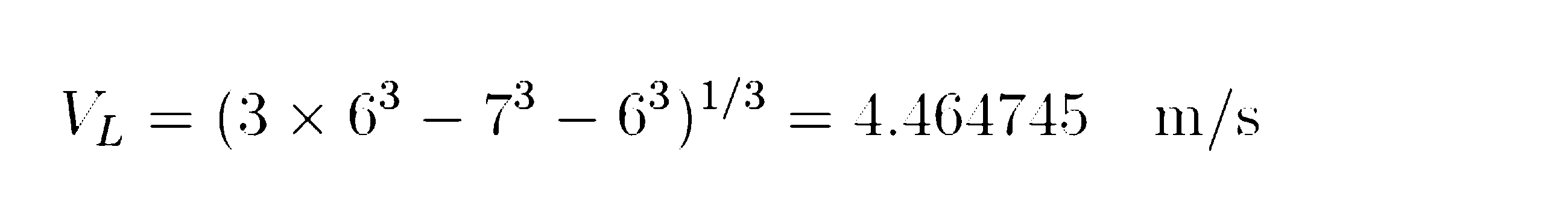
同様に低速域(基準風速3m/s)では、3段階の風速のうち中速VMを基準流速VM=3m/s、高速VHをVH=3.5m/sとした場合、低速VLは運動エネルギー流量一定の条件(数14)に、それぞれVHおよびVMを代入し、数17に示すVL=2.23m/sを得る。

一方、Cpを算出は上記数1~数13に示すいわゆる多流管のダブルアクチュエータ法にて行い、垂直型ブレード1の計算条件は、翼型データとして特定の対象翼の揚力係数及び抗力係数と迎角の関係を用い、風速は上記のデータを設定し、翼直径は4m、翼弦長29は30cm、直線翼2の長さは4m、直線翼2の枚数は3枚とし同心円は1重としている。
Cpを最大とする最適なピッチ角39の探索は、図14(a)に示すx軸正の方向を基準としたブレード回転角度13(θ)を10度刻みとして、一回転360度を36ゾーンに等分割し、順番に1~36ゾーンとしている。最適なピッチ角39の探索の一例を図15~17に示す。横軸はゾーン19(ブレード回転角度13が180度~190度)におけるピッチ角39(PITCH ANGLE)、縦軸はCp(CPと表す)を示す。
図15(a)は高速域(基準風速12m/s)における周速比3の条件の結果を、図15(b)は高速域(基準風速12m/s)における周速比0.5の条件の結果をそれぞれ示している。
また、図16(a)は中速域(基準風速6m/s)における周速比3の条件の結果を、図16(b)は中速域(基準風速6m/s)における周速比0.5の条件の結果をそれぞれ示している。
さらに、図17(a)は低速域(基準風速3m/s)における周速比3の条件の結果を、図17(b)は低速域(基準風速3m/s)における周速比0.5の条件の結果をそれぞれ示している。
図15~図17では、条件1~条件4の4つの条件におけるCPの結果を示しており、条件1における固定ピッチ/風速分布無しに対する風速分布(流速分布)を付加した効果、ピッチ角39の調整の効果、風速分布を付加しさらにピッチ角39を調整した効果をそれぞれ示している。
図15に示す高速域では、周速比3の時、固定ピッチ/風速分布無しに対して風速分布を付加した結果約20%CPが上昇し、一方ピッチ角39の調整の結果約10%CPが上昇し、風速分布を付加しさらにピッチ角39を調整した結果約30%CPが上昇している。
また、周速比0.5の条件では、固定ピッチ/風速分布無しに対して風速分布を付加した結果ほぼ0から0.1程度へとCPが大幅に上昇し、ピッチ角39の調整の効果はあまりないことがわかる。
同様に、図16に示す中速域では、周速比3の条件では、固定ピッチ/風速分布無しに対して風速分布を付加した結果約15%CPが上昇し、一方ピッチ角39の調整の結果約10%CPが上昇し、風速分布を付加しさらにピッチ角39を調整した結果約25%CPが上昇している。
また、周速比0.5の条件では、固定ピッチ/風速分布無しに対して風速分布を付加した結果ほぼ0から0.1程度へとCPが大幅に上昇し、ピッチ角39の調整の効果がないことがわかる。
同様に、図17に示す低速域では、周速比3の条件では、固定ピッチ/風速分布無しに対して風速分布を付加した結果約5%CPが上昇し、一方ピッチ角39の調整の結果約20%CPが上昇し、風速分布を付加しさらにピッチ角39を調整した結果約30%CPが上昇している。
また、周速比0.5の条件では、固定ピッチ/風速分布無しに対して風速分布を付加した結果ほぼ0から0.08程度へとCPが大幅に上昇し、ピッチ角39の調整の効果は小さいことがわかる。
以上のように、周速比が大きいときは、高速域および中速域の場合、ピッチ角39の調整および流速分布の付加は効果が大きく、低速域ではピッチ角39の調整の効果が大きい。
また、周速比が小さいときは、高速域、中速域、低速域ともにピッチ角39の調整の効果が大きい。
また、周速比が小さいときは、高速域、中速域、低速域ともにピッチ角39の調整の効果が大きい。
このように、それぞれの風速、周速比においてCPの改善効果に差はあるが、流速分布の付加、ピッチ角39の角度調整、流速分布の付加とピッチ角39の調整はいずれも大きな効果があることがわかる。
尚、この計算においては流速分布の付加とピッチ角の調整の効果を算出するために上記の計算方法で行ったが、実際の垂直型風力発電システム15または垂直型水力発電システム15における流速分布および圧力分布とは差が生じるため、CP改善効果には誤差を含むものとする。
尚、この流速分布は圧力を一定とした前提のもと、運動エネルギー流量一定の条件を用いた計算により算出している。したがって、現実的には垂直型ブレード1と同等の受風面積の一様流から、同一の流速分布を精度よく実現することは困難となる。
しかしながら、上記のような流速分布を作成し、上記のようなCp改善効果を得るという方向性は問題ない。また、一様流と流速分布の関係を、圧力分布や風車の回転や効率を考慮して、精度よく検証するには、CFDなどの熱流体解析を別途行うことが必要となる。
図18(a)および(b)は、図14(b)の高速域の回転トルクの発生量をさらに詳しく示した図である。
図18(a)および(b)は、図14(b)の高速域の回転トルクの発生量をさらに詳しく示した図である。
図18(a)は条件1(風速分布無し)および条件2(風速分布有り)に対しての周速比とCpの関係を示し、図18(b)は図18(a)でもっともCPの差が大きな周速比3.5における周速比3.5における垂直型ブレード1が一回転する間の、ブレード回転角度13とトルク係数(torque coefficient)を示した図である。この条件では、ブレード回転角度13が180度付近で最も発生トルクが大きくなっていることがわかる。
従って、垂直型ブレード1の発生する接線方向の回転力が最も高くなるブレード回転角度13の特定の領域に水または空気の流速エネルギーを集中させることで、垂直型ブレード1の発電効率が最も高くなるブレード回転角度13あるいは、揚力および効力による接線方向への回転力が高いブレード回転角度13の付近に流速を集中させることができ、回転エネルギー変換効率および発電効率に優れ、発電量の多い垂直型風力発電システムまたは垂直型水力発電システムを実現することが可能となる。
図18(b)の垂直型ブレード1の1回転あたり回転トルクの出力特性より、90度~270度の間となり、180度がピークとなっている。従って、垂直型ブレード1の翼直径26に対して、流束(または流速)と直交する面内において、前記垂直型ブレード1の直径の30%~85%となる略中心部分の領域の流速または、前記ブレード回転角度13における110度から250度の領域の流速を上げ、それ以外の分割領域の流速を低下させる構成とすることで、Cpを大幅に向上させることが可能となる。
図19(a)および(b)は、図14(b)の低速域の発生トルク特性をさらに詳しく示した図である。
図19(a)および(b)は、図14(b)の低速域の発生トルク特性をさらに詳しく示した図である。
図19(a)は条件1(風速分布無し)および条件2(風速分布有り)に対しての周速比とCp(CP)の関係を示し、図19(b)は図19(a)で低周速比の領域となる周速比が0.5における垂直型ブレード1が一回転する間の、ブレード回転角度13とトルク係数を示した図である。この条件では、ブレード回転角度13が90度付近で発生トルクが負の回転トルクとなっており、この負の回転トルクが風速分布を付加することにより大きく低減していることがわかる。
従って、特に低速域で低周速比の条件においては、垂直型ブレード1の発生する回転トルクを抑制する負の回転トルクを、ブレード回転角度13の特定の領域に水または空気の流速エネルギーを集中させることで、大幅に低減することが可能となり、起動特性に優れた垂直型風力発電システムまたは垂直型水力発電システムを実現することが可能となる。
尚、実施形態2では流速分布付加装置52は、垂直型ブレード1への空気または水の流入面において、水平方向(Y方向)に3つ以上の分割領域を想定した長方形断面において、略中心部分の分割領域の流速を上げ、それ以外の分割領域の流速を低下させた構成としてもよいし、最も発生トルクが高いブレード回転角度13のゾーン付近に、流速分布を構成としてもよい。
尚、実施形態2では、垂直型ブレード1は2重の同心円構成としたが、1重でもよいし、3重でもよい。また、相対角度8の回転調整は特定の同心円上の直線翼2のみ行ってもよいし、相対角度8の角度調整をすべての直線翼2で行わない構成でもよい。
さらに、流速分布付加装置52は、垂直型ブレード1の投影面積より大きな領域の流速を集めることとしたが、垂直型ブレード1と同程度の投影面積の領域の流速を集める構成でもよいし、スライドさせて流速を集める領域を調整できる構成でもよいし、流速分布付加装置52の取り付け角度を可変とする構成でもよい。
尚、実施形態2では、流速分布付加装置52はフレーム50に対して回動またはスライド可能な状態で固定され、流速、流量に応じて流速分布のパターンを可変とする構成としてもよいし、垂直型ブレード1に流入する上流側の流体の投影面積を調整できる構成としてもよい。
この構成により、比較的簡単な構成で様々な流速分布を形成することができることに加え短時間に高精度な流速分布を形成することが可能となるため、簡素かつ安価で高精度な流速分布付加装置52を実現でき、設備コストの低減をはかるとともに、回転エネルギー変換効率および発電効率に優れ、発電量が多く投資回収効率の高い垂直型風力発電システム15または垂直型水力発電システム15を実現することが可能となる。
尚、実施形態2では仕切り部51を設けたが、流束の干渉により発電効率が低下することを考慮して、仕切り部51を無くする構成でもよい。
この構成により、比較的簡単な構成で様々な流速分布を形成することができることに加え短時間に高精度な流速分布を形成することが可能となるため、簡素かつ安価で高精度な流速分布付加装置52を実現でき、設備コストの低減をはかるとともに、回転エネルギー変換効率および発電効率に優れ、発電量が多く投資回収効率の高い垂直型風力発電システム15または垂直型水力発電システム15を実現することが可能となる。
尚、実施形態2では仕切り部51を設けたが、流束の干渉により発電効率が低下することを考慮して、仕切り部51を無くする構成でもよい。
また、フレーム50の、天面54、底面55、仕切り部51などの構成面は、軽量化および流速抵抗を減らすため、図12に示すような板でもよいし、枠だけの中空やシャフトユニット保持部7などの中心部を部分的に残しそれ以外はくりぬいた構成でもよいし、側壁は中心部だけくりぬいた構成でもよい。この場合、フレームの内部を流束が流れるため、流束(流速)の抵抗は大きく低減されるし、大幅な軽量化も可能となる。
さらに、流速加速機構56は、サイズ、コストの観点より無くする構成でもよい。
さらに、流速加速機構56は、サイズ、コストの観点より無くする構成でもよい。
尚、実施形態2では、流速分布付加装置52は固定部53を介しフレーム50に固定する構成としたが、垂直型ブレード1およびフレーム50とは別体で構成し、垂直型ブレード1または垂直型風力発電システムまたは垂直型水力発電システムの上流側に配置する構成としてもよい。
また、実施形態2では垂直型ブレード1は2機搭載する構成としたが、振動抑制機能は低下するが、垂直型ブレード1を1機のみ搭載する構成でも問題ない。
また、実施形態2では垂直型ブレード1は2機搭載する構成としたが、振動抑制機能は低下するが、垂直型ブレード1を1機のみ搭載する構成でも問題ない。
さらに、流速分布付加装置52の構成要素となる板状の流速制御板57は、板状ではない形状でもよいことは言うまでもなく、流速分布を付加する機能があればよく、流速制御部57としてもよい。
また、流速分布付加装置52の構成要素となる板状の流速制御板57または流速制御部57は、斜め状の構成要素ではなく、図12CおよびDに示すように、開門式の構成でもよい。
図12Cおよび図12Dは、河川および水路に流速分布付加装置52と、垂直型水力発電システム15を構成した図であり、垂直型水力発電システム15の垂直型ブレード1およびフレーム50と流速分布付加装置52とは別体としている。
図12Cにおいて、流速分布付加装置52はボルトあるいは基礎工事などで垂直型ブレード1の上流側に固定され、流速分布付加装置52には固定部53を介して流速制御部57が構成されている。流速制御部57の開口サイズ58は垂直型ブレード1の直径φD(直直径26)の30%~85%またはブレード回転角度13の120度~250度の任意の値とし、その流入方向と直交する方向の開口位置59は垂直型ブレード1の回転中心にこだわらず、前記垂直型ブレード1の回転中心に対して開口位置59の中心位置のずれは前記翼直径26の0%から±30%の範囲内で設定値は翼直径26、周速比、流速、ソリディティー、ピッチ角度39に応じて任意とする。
この時、この開口サイズ58の範囲はブレード回転角度13の1回転におけるトルク係数または発生トルクの最大値の範囲があらかじめ定められた値(スレッショルド)より大きな値とすることで決定する。また、開口位置59は、垂直型ブレード1の回転中心と開口サイズ58の中心とのY方向の距離と定義する。
さらに開口部の開口サイズ58および開口位置59は、垂直型ブレード1の構成、流速、周速比の条件下における垂直型ブレード1のブレード回転角度13に対する発生トルクの関係より、Cpが最大となる開口サイズ58および開口位置59を演算して決定することとなる。
尚、この時、流速制御部57は流速および周速比によりリアルタイムで開口サイズ58をおよび開口位置59を調整する構成でもよいし、固定部53により完全に流速分布付加装置52に流速制御部57が固定されている構成でもよい。
垂直型ブレード1に流入する流体(水)の流速分布は開口部の開口サイズ58および開口位置59により決定されるが、開口部を外れたY方向位置での流速は大きく低下する構成でも良いし、比較的流速差が緩和される構成でもよい。
流速制御部57が短く、開口部と垂直型ブレード1の流れ方向の距離が近づいている場合は、垂直型ブレード1に流入する開口部の領域と開口部以外の領域でのY方向位置で流速分布の差は比較的大きいが、流速制御部57が比較的長く、開口部と垂直型ブレード1の流れ方向の距離が離れている場合は、垂直型ブレード1に流入する開口部の領域と開口部以外の領域でのY方向位置での流速分布の差は比較的小さくなる。また、流速制御部57を流れの方向に対して斜めに配置することで、流れの乱れ(乱流度合い)が小さくなり、渦も発生しにくくなるため、比較的乱れの少ない位相の揃った流速が垂直型ブレード1に流入するため、斜めの構成となる流速制御部57の構成は発電効率を維持するために大きな構成要素となる。
尚、実施形態2における流速分布付加装置52と、フレーム50および垂直型ブレード1とは一体でも良いし別体でもよい。
尚、実施形態2における流速分布付加装置52と、フレーム50および垂直型ブレード1とは一体でも良いし別体でもよい。
また、流速制御部57は流速方向に対して斜めの構成でも良いし、平行でもよいし、発電効率は下がるが、コスト低減効果があるため無くして単なる開口部としてもよい。
尚、図12Cにおける垂直型水力発電システム15の水路または河川への固定は、コンクリートなどへのボルト固定でもよいし、基礎工事などを行い、金属部品などで固定する方法でもよい。
図12Dは、河川および水路に流速分布付加装置52と、垂直型水力発電システム15を構成した図である。図12Cとの違いは、流速制御部57を斜めの角度を有した案内板ではなく、流速と略直交する面に構成された流速制御部57を上下に移動させて、開口部を形成する構成としている。この時、流速制御部57の上下方向への移動は、流速および周速比応じてリアルタイムで開口サイズ58をおよび開口位置59を調整する構成でもよいし、固定式でも良い。固定方法としてはネジ式で移動させても良いし、ボルトまたはピンなどのとめ具で固定してもよい。
また、開口部の開口サイズ58および開口位置59が固定なら、流速制御部57はなくして、単に流速分布付加装置52に開口部(穴)があいているだけでもよい。
尚、図12Dにおいて、開口部は連続して構成されているが、一定の距離を離して、開口部を形成してもよい。
尚、図12Dにおいて、開口部は連続して構成されているが、一定の距離を離して、開口部を形成してもよい。
(実施形態3)
図20(a)、(b)を参照して実施の形態3に係る垂直型風力発電システムについて説明する。実施形態1および2との差は、風向検出手段19を用い、垂直型ブレード19に流入する風の平面座標系11の回転中心Oを中心とした基準角度12に対する風向28(角度)を検出する構成とする。また、流速分布付加装置52を垂直型ブレード1の4隅に配置するとともに、固定部53の下部に回動手段9を設置し流速分布付加装置52を回動可能な状態で保持し、風向28に応じて流速分布付加装置52を回動させ、あらゆる風向(または流れの向き)に応じて常にCpを最大にする構成としたことである。
図20(a)、(b)を参照して実施の形態3に係る垂直型風力発電システムについて説明する。実施形態1および2との差は、風向検出手段19を用い、垂直型ブレード19に流入する風の平面座標系11の回転中心Oを中心とした基準角度12に対する風向28(角度)を検出する構成とする。また、流速分布付加装置52を垂直型ブレード1の4隅に配置するとともに、固定部53の下部に回動手段9を設置し流速分布付加装置52を回動可能な状態で保持し、風向28に応じて流速分布付加装置52を回動させ、あらゆる風向(または流れの向き)に応じて常にCpを最大にする構成としたことである。
この構成により、あらゆる風向、流れの向き、潮の流れの向きに応じて、常に最大のCPを維持することができ、発電効率に優れた垂直型風力発電システム15、垂直型水力発電システム15、または洋上風力発電における海中に配した垂直型水力発電システム15を実現できる。
尚、実施形態3において垂直型ブレード1への空気または水の流速を検出する流速検出手段17と流入角度を検出する風向検出手段19と回動手段9とを用い、流速分布付加装置52は、複数配置され、空気または水の流速および垂直型ブレード1への風向28(流入角度)に応じて流速分布のパターンを可変とする構成としてもよい。
また、実施の形態1~3では主に垂直型風力発電システムを本発明の適応範囲としたが、水力発電システムへ適応しても問題ないし洋上の風力発電システムまたは潮力発電システムに適応してもよい。この場合、翼素運動量理論を用いた回転角度テーブル14の演算において、流体が空気から水に変わることにより密度ρ、粘性係数および翼型特性(揚力、抗力)の情報を変更することになる。
(実施形態4)
図21A、図21B、図21C、図21Dおよび図22を参照して実施形態4に係わる垂直型水力発電システム15について説明する。
実施形態1~3との違いは、ピッチ角度39の角度制御を行った場合において、中周速比および高周速比における開口位置59と、低周速比における開口位置59が大きく異なるという点である。
図21A、図21B、図21C、図21Dおよび図22を参照して実施形態4に係わる垂直型水力発電システム15について説明する。
実施形態1~3との違いは、ピッチ角度39の角度制御を行った場合において、中周速比および高周速比における開口位置59と、低周速比における開口位置59が大きく異なるという点である。
図21Aは、流速方向に対して直交する断面において、流速分布を3つの長方形断面に分割した状態を示している。数14の運動エネルギー流量一定の条件より算出した流速分布を示しており、CASE2は中心部分が最大流速の3.5m/sとなり、それぞれ両側に3m/sと2.23m/sの流速分布を形成している。この場合、Y軸方向の中心(垂直型ブレード1の回転中心)と流速分布の最大値のY軸方向の中心はほぼ一致している。
一方CASE3は、図中において、図の下側(ブレード回転角度13が200度から340度付近)の領域の流速を最大流速と設定し、中心付近の領域を3m/s、上側を2.23m/sとそれぞれ設定している。
図21B、図21Cは、図21Aの流速分布を用い、Cpと周速比の関係を示した図で、条件3、条件4および条件5は条件1および条件2に対してCpの改善効果は大きい。これはピッチ角39の角度調整の効果が大きいといえる。
また、条件3、条件4および条件5のCp改善効果に有意差が無い。条件4(CASE2)および条件5(CASE3)のCp改善効果に有意差があまりないという結果になっている。
これは図21Dに示すように、トルク係数(発生トルク)を縦軸に取り、ブレード回転角度13を横軸にしたとき条件3ではブレード回転角度13が150度付近から240度にかけてトルク係数が大きく増加する。したがってその角度領域の流速をあげれば、条件4および条件5以上にトルク係数が増加することが容易に推察される。
条件4および条件5は、200度付近で最大流速が入れ替わっているため、その効果が低下しているが150度付近から240度付近の風速を上げることで、条件3に対してさらに流速分布を付加した効果が発揮できCpが増加することとなる。
この時、条件3で最大トルクを発生するブレード回転角度13は約200度付近となっており、その最大トルクを発生するブレード回転角度は180度から大きくずれることとなる。従って、開口位置59は周速比により大きく変化し、周速比が1以下の領域では、150度付近から240度付近の流速をあげることが重要となる。
図22は、実施形態4における水力発電システム15の構成例を示したもので、図12Cにおける開口位置59を大きくY軸のマイナス側にずらし、ブレード回転角度13の200度付近に開口サイズ58の中心を配置し、ブレード回転角度13の150度~240度付近の流速を上げる構成としている。
この構成により、低周速比および低流速の条件下において、垂直型水力発電システム15の発電効率を大幅に向上させることが可能となる。
この構成により、低周速比および低流速の条件下において、垂直型水力発電システム15の発電効率を大幅に向上させることが可能となる。
上記説明から、当業者にとって、本発明の多くの改良や他の実施形態が明らかである。
従って、上記説明は、例示としてのみ解釈されるべきであり、本発明を実行する最良の態様を当業者に教示する目的で提供されたものである。本発明の精神を逸脱することなく、その構造および/または機能の詳細を実質的に変更できる。
従って、上記説明は、例示としてのみ解釈されるべきであり、本発明を実行する最良の態様を当業者に教示する目的で提供されたものである。本発明の精神を逸脱することなく、その構造および/または機能の詳細を実質的に変更できる。
本発明は、従来に比べ、最適かつ緻密な垂直翼の相対角度の回転角制御を行うことにより発電効率に優れ、信頼性に優れた垂直型風力発電システムまたは水力発電システムを実現する。よって、本発明は、例えば、垂直型風力発電システムや垂直型水力発電システムに利用できる。
1 垂直型ブレード
2 直線翼
3 アーム
4 シャフトユニット
5 発電機
6 ポール
7 シャフトユニット保持部
8 相対角度
9 回動手段
10 回転角制御装置
11 平面座標系
12 基準角度
13 ブレード回転角度
14 回転角度テーブル
15 垂直型風力発電システム(水力発電システム)
16 風速
17 風速検出手段
18 回転数検出手段
19 風向検出手段
20 回転トルク
21 回転抑止トルク可変手段
22 発電機コントローラ(回転数制御手段)
23 パワーコントローラ
24 結合部
25 翼弦
26 翼直径
27 取付け部
28 風向
29 翼弦長
30 駆動源
31 動力伝達部
32 軸支部
33 回動軸部
34 翼長
35 周速
36 向周速
37 相対風速
38 迎角
39 ピッチ角度
40 揚力
41 抗力
42 揚力による回転トルク
43 抗力による回転トルク
50 フレーム
51 仕切り部
52 流速分布付加装置
53 固定部
54 天面
55 底面
56 流速加速機構
57 流束制御部(流速制御板)
58 開口サイズ
59 開口位置
60 電力源
Claims (23)
- 同心円状に少なくとも内周側と外周側の2列以上の円周上に配置された複数の直線翼から構成される垂直型ブレードと、前記直線翼を保持するアームと、前記アームと固定され前記アームの回転を支持するシャフトユニットと、前記シャフトユニットと連動し前記垂直型ブレードの回転エネルギーを電気エネルギーに変換する発電機と、前記垂直型ブレードと前記アームと前記シャフトユニットを保持するポールまたはフレームと、前記ポールまたは前記フレームが前記シャフトユニットを回動自在に保持するためのシャフトユニット保持部とを有し、
前記垂直型ブレードの最大出力を発生する時の回転数または周速比において、外周側に配置された前記垂直型ブレードの前記回転数または周速比に対して、内周側に配置された前記垂直型ブレードの前記回転数または周速比が段階的に小さくなる構成としたことを特徴とする垂直型風力発電システムまたは垂直型水力発電システム。 - 前記垂直型ブレードは、内周側の円周上に配置された前記直線翼のソリディティー(翼直径における円周の長さと翼弦長×翼枚数の比率)に対して、外周側の円周上に配置された前記直線翼のソリディティーを段階的に大きくしたことを特徴とする請求項1記載の垂直型風力発電システムまたは垂直型水力発電システム。
- 風又は水の流速と、垂直型ブレードの回転速度である周速に対する向流速との合成となる相対流速と、直線翼の前縁と後縁とを結んだ線分となる翼弦とのなす角度である迎角において、接線方向の回転力が大きくなるような迎角にするために相対角度を変化させることを目的として、前記相対角度は前記翼弦とアームとの角度、または前記翼弦と前記直線翼の保持位置における接線方向との角度として、
前記垂直型ブレードの回転面内において、前記直線翼の前記相対角度をそれぞれ独立して回動させる回動手段と、
前記回動手段により前記相対角度を制御する回転角制御装置と、
前記垂直型ブレードの回転中心を基準した平面座標系における基準角度からの前記垂直型ブレードまたは個々の前記直線翼のブレード回転角度と、前記流速を検出する流速検出手段と、
前記垂直型ブレードの回転数を検出する回転数検出手段と、
前記流速、前記回転数または周速比、前記ブレード回転角度から演算した前記相対角度の回転角度テーブルとを有し、
前記回転角度テーブルをもとに前記直線翼の前記回転角制御装置を用い、同心円状に少なくとも内周側と外周側の2列以上の円周上に配置された複数の前記直線翼おいて、全ての前記直線翼または特定の同心円上の前記直線翼のみ前記ブレード回転角度に応じて前記直線翼の前記相対角度を制御することを特徴とする垂直型風力発電システムまたは垂直型水力発電システム。 - 2重または3重の同心円上に配置された複数の前記直線翼を有した前記垂直型ブレードにおいて、最内周または最外周以外の前記直線翼のみ前記ブレード回転角度に応じて前記直線翼の前記相対角度を制御することを特徴とする請求項3に記載の垂直型風力発電システムまたは垂直型水力発電システム。
- 複数の直線翼から構成される垂直型ブレードと、前記垂直型ブレードまたは前記直線翼を保持するアームと、前記アームと固定され前記アームの回転を支持するシャフトユニットと、前記シャフトユニットと連動し前記垂直型ブレードの回転エネルギーを電気エネルギーに変換する発電機と、前記垂直型ブレードと前記アームと前記シャフトユニットを保持するポールまたはフレームと、前記ポールまたは前記フレームが前記シャフトユニットを回動自在に保持するためのシャフトユニット保持部と、前記ポールまたは前記フレームに固定または前記垂直型ブレードの流入面側に個別に設置され、前記垂直型ブレードに流入する風又は水に所望の流速分布を生じさせる流速分布付加装置とを備えたことを特徴とする垂直型風力発電システムまたは垂直型水力発電システム。
- 前記流速分布は、前記垂直型ブレードへの風または水の流入面と直交する長方形断面において、前記垂直型ブレードの直径の30%~85%となる略中心部分の領域の流速または前記直線翼のブレード回転角度における120度から250度の領域の流速を上げ、それ以外の分割領域の流速を低下させるとともに、流束を上げた前記領域の中心位置と前記垂直型ブレードの回転中心との前記流入面と直交する方向のずれは、前記垂直型ブレードの直径の0%±30%の範囲とすることを特徴とする請求項5記載の垂直型風力発電システムまたは垂直型水力発電システム。
- 前記垂直型ブレードへの風または水の流速を検出する流速検出手段および/または流入角度を検出する流入角度検出装置とを有し、前記流速分布付加装置は、複数の流速制御手段により構成され、風または水の流速および前記垂直型ブレードへの前記流入角度に応じて前記流速分布のパターンを可変とすることを特徴とした請求項5又は請求項6記載の垂直型風力発電システムまたは垂直型水力発電システム。
- 前記流速分布は、前記垂直型ブレードへの風または水の流入面と直交する長方形断面において、流量、流速、前記垂直型ブレードの回転数または周速比、流入角度のいずれか一つ以上の条件に応じて、前記垂直型ブレードの直径の30%~85%となり、かつ略中心部に限定されない任意の断面の領域の流速を上げ、それ以外の領域の流速を低下させることを特徴とする請求項5から請求項7のいずれかに記載の垂直型風力発電システムまたは垂直型水力発電システム。
- 前記流速制御手段は、前記流速制御手段に対して回動またはスライドする流束分布制御部により前記流速分布を可変とすることを特徴とした請求項7又は請求項8のいずれかに記載の垂直型風力発電システムまたは垂直型水力発電システム。
- 前記直線翼の前記相対角度、前記流速分布を、前記流速、前記流入角度、および前記周速比のいずれか一つ以上の条件に応じて可変とすることを特徴とする請求項1から請求項9のいずれかに記載の垂直型風力発電システムまたは垂直型水力発電システム。
- 前記流速分布付加装置により、風または水の流れの方向における前記垂直型ブレードの投影面積に対して、前記垂直型ブレードに流入する風または水の流入面積を大きくしたことを特徴とする請求項5及び、請求項1から請求項10のいずれかに記載の垂直型風力発電システムまたは垂直型水力発電システム。
- 前記流速分布付加装置により、風または水を前記垂直型ブレードに流入させる前記流入面積を、風または水の流量または水の流速に応じて可変とすることを特徴とする請求項11記載の垂直型風力発電システムまたは垂直型水力発電システム。
- 2重または3重の同心円上に配置された複数の前記直線翼を有した前記垂直型ブレードにおいて、すべてまたは特定の同心円上の前記直線翼のみ、前記垂直型ブレード回転角度に応じて前記直線翼の前記相対角度を回転トルクが低減する角度に制御することを特徴とする請求項1から請求項12のいずれかに記載の垂直型風力発電システムまたは垂直型水力発電システム。
- 相対角度調整モードを有し、前記流速、前記回転数または前記周速比、前記ブレード回転角度に応じた前記直線翼における前記相対角度の角度調整を行い、発電効率が最大となる前記相対角度の所定固定角度または前記回転角度テーブルを作成することを特徴とする請求1から請求項13のいずれかに記載の垂直型風力発電システムまたは垂直型水力発電システム。
- 風または水の前記流速検出手段と、前記垂直型ブレードの前記回転数検出手段を用い、前記相対角度調整モードにおいて、前記直線翼を1枚ごとに前記相対角度調整を行い、前記流速、前記回転数または前記周速比、前記発電効率または出力特性の関係を取得し、それぞれの前記直線翼を最大出力となる前記相対角度に自動的に調整することを特徴とする請求項14記載の垂直型風力発電システムまたは垂直型水力発電システム。
- 出力検査モードを有し、記憶された前回の前記発電効率または発電量などの出力特性と定期的に比較し発電状態を把握するとともに、予め設定した出力特性の変化量を超えた場合は前記相対角度調整モードを実施することで定期的に前記相対角度のメンテナンスを行うことを特徴とする請求項14又は請求項15記載の垂直型風力発電システムまたは垂直型水力発電システム。
- 前記フレームに、前記垂直型ブレードに流入した風または水の前記流速を増加させる流速加速機構を備えたことを特徴とした請求項1から請求項16のいずれかに記載の垂直型風力発電システムまたは垂直型水力発電システム。
- 前記流速加速機構は、風または水の通過する流路幅を狭くすることを特徴とする請求項17記載の垂直型風力発電システムまたは垂直型水力発電システム。
- 前記フレームのそれぞれ独立した空間に前記垂直型ブレードを2機搭載し、それぞれの回転方向が逆回転となるように前記垂直型ブレードを構成する前記直線翼の前記前縁および前記後縁の方向および前記相対角度を設定したことを特徴とする請求項1から請求項18のいずれかに記載の垂直型風力発電システムまたは垂直型水力発電システム。
- 前記垂直型ブレードの回転に伴い揚力および抗力より発生する水平面内のXY平面におけるX方向の発生力とY方向の発生力により前記フレームに作用する力が、それぞれ相殺されて最小になるようにそれぞれの前記直線翼を配置した構成としたことを特徴とする請求項19記載の垂直型風力発電システムまたは垂直型水力発電システム。
- 前記垂直型ブレードに流入する風または水の前記流速または流量が必要以上に大きい場合は、前記相対角度を制御し発電効率を低下させるか、前記流速分布付加装置により前記垂直型ブレードに流入する前記流速または前記流量を低減させる構成としたことを特徴とする請求項1から請求項20のいずれかに記載の垂直型風力発電システムまたは垂直型水力発電システム。
- 風又は水の流速と、垂直型ブレードの回転速度である周速に対する向流速との合成となる相対流速と、直線翼の前縁と後縁とを結んだ線分となる翼弦とのなす角度である迎角において、接線方向の回転力が大きくなるような迎角にするために相対角度を変化させることを目的として、前記相対角度は前記翼弦とアームとの角度、または前記翼弦と前記直線翼の保持位置における接線方向との角度として、前記垂直型ブレードの回転面内において、前記直線翼の前記相対角度をそれぞれ独立して回動可能に構成し、
前記相対角度を制御する回転角制御装置と、前記垂直型ブレードの回転中心を基準した平面座標系における基準角度からの前記垂直型ブレードまたは個々の前記直線翼のブレード回転角度と、前記流速を検出する流速検出手段と、前記垂直型ブレードの回転数を検出する回転数検出手段と、前記流速、前記回転数または周速比、前記ブレード回転角度から演算した前記相対角度の回転角度テーブルとを用い、
前記回転角度テーブルをもとに前記直線翼の前記回転角制御装置を用い、同心円状に少なくとも内周側と外周側の2列以上の円周上に配置された複数の前記直線翼おいて、全ての前記直線翼または特定の同心円上の前記直線翼のみ前記ブレード回転角度に応じて前記直線翼の前記相対角度を制御することを特徴とする垂直型風力発電システムまたは垂直型水力発電システムにおける制御方法。 - 前記請求項3に記載の垂直型風力発電システムまたは垂直型水力発電システムにおける、回転角制御装置。
Applications Claiming Priority (2)
| Application Number | Priority Date | Filing Date | Title |
|---|---|---|---|
| JP2015-256795 | 2015-12-28 | ||
| JP2015256795A JP2017120050A (ja) | 2015-12-28 | 2015-12-28 | 垂直型風力発電システム、垂直型水力発電システム、およびその制御方法 |
Publications (1)
| Publication Number | Publication Date |
|---|---|
| WO2017115565A1 true WO2017115565A1 (ja) | 2017-07-06 |
Family
ID=59224932
Family Applications (1)
| Application Number | Title | Priority Date | Filing Date |
|---|---|---|---|
| PCT/JP2016/083632 WO2017115565A1 (ja) | 2015-12-28 | 2016-11-14 | 垂直型風力発電システム、垂直型水力発電システム、およびその制御方法 |
Country Status (2)
| Country | Link |
|---|---|
| JP (1) | JP2017120050A (ja) |
| WO (1) | WO2017115565A1 (ja) |
Cited By (2)
| Publication number | Priority date | Publication date | Assignee | Title |
|---|---|---|---|---|
| CN112459951A (zh) * | 2020-11-25 | 2021-03-09 | 汪兴华 | 一种用于风向多变地区的风力辅助式水利发电装置及方法 |
| CN114198260A (zh) * | 2021-12-14 | 2022-03-18 | 西南石油大学 | 一种高效垂直轴开关磁阻微风发电机 |
Families Citing this family (4)
| Publication number | Priority date | Publication date | Assignee | Title |
|---|---|---|---|---|
| JP7213011B2 (ja) * | 2017-09-25 | 2023-01-26 | Ntn株式会社 | 水力発電装置用の流路規制装置 |
| CA2993857A1 (en) * | 2018-02-02 | 2019-08-02 | Ferguson Technologies Inc. | Systems and methods for generating electrical energy |
| JP7040792B2 (ja) * | 2019-10-15 | 2022-03-23 | 力也 阿部 | 揚力型垂直軸風水車 |
| JP2023174466A (ja) * | 2022-05-27 | 2023-12-07 | 三鷹光器株式会社 | 増風機構付き垂直軸風車構造 |
Citations (11)
| Publication number | Priority date | Publication date | Assignee | Title |
|---|---|---|---|---|
| JP2001107838A (ja) * | 1999-08-02 | 2001-04-17 | Hirai Sekkei Jimusho:Kk | 風車およびその制御方法 |
| JP2005061318A (ja) * | 2003-08-12 | 2005-03-10 | Toshiba Plant Systems & Services Corp | 多段風力発電装置 |
| JP2005090332A (ja) * | 2003-09-17 | 2005-04-07 | Satsuki Seisakusho:Kk | ダリウス形風車 |
| WO2006123951A1 (en) * | 2005-05-18 | 2006-11-23 | Leonard Charles Wicks | A wind turbine |
| JP2007224870A (ja) * | 2006-02-27 | 2007-09-06 | Japan Aircraft Mfg Co Ltd | 縦軸型風力発電装置 |
| JP2008038673A (ja) * | 2006-08-03 | 2008-02-21 | Masataka Murahara | 海洋電気分解工場 |
| JP2008063960A (ja) * | 2006-09-05 | 2008-03-21 | Masataka Murahara | 洋上浮体式風水車流体抽出発電設備 |
| US20080247872A1 (en) * | 2007-01-22 | 2008-10-09 | Lonestar Inventions Lp | Method of Operation of a High-Efficiency Turbine With Variable Attack Angle Foils |
| KR20120088958A (ko) * | 2011-02-01 | 2012-08-09 | 에너진(주) | 풍력발전기용 로터 |
| JP2013170566A (ja) * | 2012-02-23 | 2013-09-02 | Mitsubishi Heavy Ind Ltd | 風力発電装置の監視方法及びシステム |
| WO2015040539A1 (en) * | 2013-09-17 | 2015-03-26 | Genius Energy Srl | Vertical axis wind turbine rotor |
Family Cites Families (1)
| Publication number | Priority date | Publication date | Assignee | Title |
|---|---|---|---|---|
| JP5924125B2 (ja) * | 2012-05-23 | 2016-05-25 | 学校法人立命館 | 垂直軸風車用ブレード及び垂直軸風車 |
-
2015
- 2015-12-28 JP JP2015256795A patent/JP2017120050A/ja active Pending
-
2016
- 2016-11-14 WO PCT/JP2016/083632 patent/WO2017115565A1/ja active Application Filing
Patent Citations (11)
| Publication number | Priority date | Publication date | Assignee | Title |
|---|---|---|---|---|
| JP2001107838A (ja) * | 1999-08-02 | 2001-04-17 | Hirai Sekkei Jimusho:Kk | 風車およびその制御方法 |
| JP2005061318A (ja) * | 2003-08-12 | 2005-03-10 | Toshiba Plant Systems & Services Corp | 多段風力発電装置 |
| JP2005090332A (ja) * | 2003-09-17 | 2005-04-07 | Satsuki Seisakusho:Kk | ダリウス形風車 |
| WO2006123951A1 (en) * | 2005-05-18 | 2006-11-23 | Leonard Charles Wicks | A wind turbine |
| JP2007224870A (ja) * | 2006-02-27 | 2007-09-06 | Japan Aircraft Mfg Co Ltd | 縦軸型風力発電装置 |
| JP2008038673A (ja) * | 2006-08-03 | 2008-02-21 | Masataka Murahara | 海洋電気分解工場 |
| JP2008063960A (ja) * | 2006-09-05 | 2008-03-21 | Masataka Murahara | 洋上浮体式風水車流体抽出発電設備 |
| US20080247872A1 (en) * | 2007-01-22 | 2008-10-09 | Lonestar Inventions Lp | Method of Operation of a High-Efficiency Turbine With Variable Attack Angle Foils |
| KR20120088958A (ko) * | 2011-02-01 | 2012-08-09 | 에너진(주) | 풍력발전기용 로터 |
| JP2013170566A (ja) * | 2012-02-23 | 2013-09-02 | Mitsubishi Heavy Ind Ltd | 風力発電装置の監視方法及びシステム |
| WO2015040539A1 (en) * | 2013-09-17 | 2015-03-26 | Genius Energy Srl | Vertical axis wind turbine rotor |
Cited By (3)
| Publication number | Priority date | Publication date | Assignee | Title |
|---|---|---|---|---|
| CN112459951A (zh) * | 2020-11-25 | 2021-03-09 | 汪兴华 | 一种用于风向多变地区的风力辅助式水利发电装置及方法 |
| CN114198260A (zh) * | 2021-12-14 | 2022-03-18 | 西南石油大学 | 一种高效垂直轴开关磁阻微风发电机 |
| CN114198260B (zh) * | 2021-12-14 | 2024-01-16 | 西南石油大学 | 一种高效垂直轴开关磁阻微风发电机 |
Also Published As
| Publication number | Publication date |
|---|---|
| JP2017120050A (ja) | 2017-07-06 |
Similar Documents
| Publication | Publication Date | Title |
|---|---|---|
| WO2017115565A1 (ja) | 垂直型風力発電システム、垂直型水力発電システム、およびその制御方法 | |
| US20200362813A1 (en) | Fluid turbine systems | |
| JP6128575B2 (ja) | 流体発電方法及び流体発電装置 | |
| JP4035537B2 (ja) | 垂直軸風車等の垂直軸駆動装置およびこれを用いた発電装置 | |
| US8786123B2 (en) | Turbine assembly | |
| CN101832225B (zh) | 升力型垂直轴风力发电机风轮结构 | |
| US20100054936A1 (en) | Vertical axis wind turbine | |
| US20110194938A1 (en) | Segmented wind turbine airfoil/blade | |
| US10233901B2 (en) | Turbine for capturing energy from a fluid flow | |
| US20140271216A1 (en) | Horizontal axis wind or water turbine with forked or multi-blade upper segments | |
| JP2019060345A5 (ja) | ||
| Batista et al. | New blade profile for Darrieus wind turbines capable to self-start | |
| Guang et al. | Hydrodynamic performance of a vertical-axis tidal-current turbine with different preset angles of attack | |
| Zhang et al. | Vertical axis wind turbine with individual active blade pitch control | |
| KR20120061264A (ko) | 다중 종속 블레이드를 갖는 수직축형 터빈 | |
| US20150110627A1 (en) | Blade bucket structure for savonius turbine | |
| CN205578183U (zh) | 一种自适应变桨的垂直轴风力驱动装置及风力发电机 | |
| JP6954739B2 (ja) | 発電機用のロータ | |
| Kubo et al. | Development of intelligent wind turbine unit with tandem wind rotors and double rotational armatures (2nd report, characteristics of tandem wind rotors) | |
| WO2017110298A1 (ja) | 風車システムまたはウィンドファーム | |
| JP6574634B2 (ja) | 垂直型風力発電システム、及び垂直型風力発電システムにおける制御方法 | |
| Soraghan et al. | Influence of lift to drag ratio on optimal aerodynamic performance of straight blade vertical axis wind turbines | |
| GB2513674A (en) | Vertical wind turbine with constant output speed | |
| KR20110083476A (ko) | 항력과 양력을 동시에 이용하는 수직축 풍력터빈 | |
| JP6904766B2 (ja) | 垂直軸風車および風力発電装置 |
Legal Events
| Date | Code | Title | Description |
|---|---|---|---|
| 121 | Ep: the epo has been informed by wipo that ep was designated in this application |
Ref document number: 16881545 Country of ref document: EP Kind code of ref document: A1 |
|
| NENP | Non-entry into the national phase |
Ref country code: DE |
|
| 122 | Ep: pct application non-entry in european phase |
Ref document number: 16881545 Country of ref document: EP Kind code of ref document: A1 |