WO2017114557A1 - Height adjustable foot with improved grip - Google Patents
Height adjustable foot with improved grip Download PDFInfo
- Publication number
- WO2017114557A1 WO2017114557A1 PCT/EP2015/081325 EP2015081325W WO2017114557A1 WO 2017114557 A1 WO2017114557 A1 WO 2017114557A1 EP 2015081325 W EP2015081325 W EP 2015081325W WO 2017114557 A1 WO2017114557 A1 WO 2017114557A1
- Authority
- WO
- WIPO (PCT)
- Prior art keywords
- height adjustable
- cavity
- adjustable foot
- support
- suction pad
- Prior art date
- Legal status (The legal status is an assumption and is not a legal conclusion. Google has not performed a legal analysis and makes no representation as to the accuracy of the status listed.)
- Ceased
Links
Images

Classifications
-
- D—TEXTILES; PAPER
- D06—TREATMENT OF TEXTILES OR THE LIKE; LAUNDERING; FLEXIBLE MATERIALS NOT OTHERWISE PROVIDED FOR
- D06F—LAUNDERING, DRYING, IRONING, PRESSING OR FOLDING TEXTILE ARTICLES
- D06F39/00—Details of washing machines not specific to a single type of machines covered by groups D06F9/00 - D06F27/00
- D06F39/12—Casings; Tubs
- D06F39/125—Supporting arrangements for the casing, e.g. rollers or legs
-
- A—HUMAN NECESSITIES
- A47—FURNITURE; DOMESTIC ARTICLES OR APPLIANCES; COFFEE MILLS; SPICE MILLS; SUCTION CLEANERS IN GENERAL
- A47B—TABLES; DESKS; OFFICE FURNITURE; CABINETS; DRAWERS; GENERAL DETAILS OF FURNITURE
- A47B91/00—Feet for furniture in general
- A47B91/02—Adjustable feet
-
- A—HUMAN NECESSITIES
- A47—FURNITURE; DOMESTIC ARTICLES OR APPLIANCES; COFFEE MILLS; SPICE MILLS; SUCTION CLEANERS IN GENERAL
- A47L—DOMESTIC WASHING OR CLEANING; SUCTION CLEANERS IN GENERAL
- A47L15/00—Washing or rinsing machines for crockery or tableware
- A47L15/42—Details
- A47L15/4251—Details of the casing
- A47L15/4253—Supporting arrangements for the casing, e.g. rollers or supporting legs
Definitions
- the present invention relates to a household appliance, in particular to a laundry treatment appliance such as a laundry washer or a laundry washer-and-dryer.
- the present invention more particularly relates to the height adjustable feet of the household appliance.
- a laundry washer generally comprises a main body which includes a rotating drum for receiving the laundry and height adjustable feet which are disposed onto the bottom of the main body.
- the height adjustable foot generally comprises a support which is height adjustably mounted to the main body of the laundry washer. In order to compensate for any irregularities in the floor, the service person adjusts during the installation of the laundry washer the height adjustable feet so as to align the laundry washer horizontally and thus give the laundry washer a secure stand.
- US 7,556,227 B2 discloses a laundry washer which has height adjustable feet.
- a common problem with the prior art laundry washer is that after the laundry washer has been taken into operation, particularly during the spin drying step, the laundry dryer is subjected to excessive mechanical stresses which cause the machine to shift. In order to counteract the shifting of the laundry washer, the moving parts must be correctly balanced and the height adjustable feet must grip well on the floor.
- An objective of the present invention is to provide a height adjustable foot for use in a household appliance which overcomes the aforementioned problems of the prior art in a cost-effective way and which enables the household appliance to stand safely and securely on the floor.
- the height adjustable foot of the present invention comprises a cavity which is formed into the lower surface of the support, a rubber suction pad which is attached to the lower surface of the support and covers the cavity and a leaf spring which is disposed into the cavity at the back of the rubber suction pad, wherein the rubber suction pad and the leaf spring are adapted to flex outwardly out of the cavity prior to pressing the support onto the floor, and wherein the rubber suction pad and the leaf spring are adapted to flex inwardly into the cavity after the support has been pressed onto the floor.
- a major advantageous effect of the present invention is that the laundry dryer can be prevented from shifting by virtue of the suction effect that is generated through the rubber suction pad.
- Another major advantageous effect of the present invention is that the mechanical wear in the contact area of the height adjustable foot can be reduced as much as possible by virtue of the rubber suction pad, and thus the grip characteristic can be constantly maintained over the whole life of the household appliance.
- Another major advantageous effect of the present invention is that the suction effect can be sustained by virtue of the spring leaf that flexes into the cavity solely under the weight of the household appliance. Thereby, an improved grip can be easily established during the installation of the household appliance. With the present invention the user satisfaction can be increased.
- one or more air vents are formed into the support so as to evacuate the cavity. This embodiment is particularly advantageous as the cavity can be more effectively evacuated when the leaf spring and the rubber suction pad are flexed inwardly during the installation.
- the support has a threaded shaft and a round base.
- the cavity is formed into the round base. This embodiment is particularly advantageous as the round base achieves a large contact area with the floor, and thus gives a secure stand to the household appliance.
- the rubber suction pad encloses also the periphery and the upper surface of the round base.
- the threaded shaft projects through an aperture on the rubber suction pad.
- the cavity and the leaf spring have matching spherical shapes. This embodiment is particularly advantageous as the suction effect can be increased, and thus the grip can be further improved.
- the leaf spring is joined to the back of the rubber suction pad through an adhesive or embedded into the rubber suction pad during the molding process. These embodiments are particularly advantageous as the spring leaf and the rubber suction pad can be more effectively flexed into the cavity.
- Figure 1 - is a perspective view of a height adjustable foot according to an embodiment of the present invention.
- Figure 2 - is another perspective view of the height adjustable foot of Fig. 1;
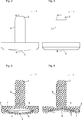
- Figure 3 - is a side view of the height adjustable foot of Fig. 1, prior to pressing the height adjustable foot onto the floor;
- Figure 4 - is a side view of the height adjustable foot of Fig. 1, after the height adjustable foot has been pressed onto the floor;
- Figure 5 - is a sectional view of the height adjustable foot of Fig. 3, taken along the line A-A;
- Figure 6 - is a sectional view of the height adjustable foot of Fig. 3, taken along the line B-B.
- the height adjustable foot (1) is suitable for use in a household appliance (not shown), in particular a laundry washer.
- the household appliance comprises a main body.
- the height adjustable foot (1) comprises a support (2) (Fig. 1 and Fig. 2).
- the support (2) is adapted to be height adjustably mounted to the main body of the household appliance.
- the height adjustable foot (1) further comprises a cavity (3) which is formed into the lower surface of the support (2), a rubber suction pad (4) which is attached to the lower surface of the support (2) and covers the cavity (3) and a leaf spring (5) which is disposed into the cavity (3) at the back of the rubber suction pad (4) (Fig. 5).
- the rubber suction pad (4) and the leaf spring (5) are adapted to flex outwardly out of the cavity (3) prior to pressing the support (2) onto the floor (Fig. 3 and Fig. 5).
- the rubber suction pad (4) and the leaf spring (5) are adapted to flex inwardly into the cavity (3) after the support (2) has been pressed onto the floor (Fig. 4 and Fig. 6).
- the household appliance in particular the laundry washer of the present invention comprises one or more height adjustable feet (1).
- the height adjustable foot (1) further comprises one or more air vents (not shown) which are formed into the support (2) and open into the cavity (3).
- the support (3) comprises a threaded shaft (6) and a round base (7) which is disposed onto the lower end of the threaded shaft (6).
- the diameter of the round base (7) is larger than the diameter of the threaded shaft (6).
- the cavity (3) is formed into the lower surface of the round base (7). In this embodiment, the cavity (3) is centered (Fig. 5 and Fig. 6).
- the support (2) is provided as a single piece made from metal.
- the rubber suction pad (4) further comprises cylindrical walls (8) which also enclose the periphery and the upper surface of the round base (7).
- an aperture (9) is formed into the rubber suction pad (4). The aperture (9) accommodates the threaded shaft (6) (Fig. 5 and Fig. 6).
- the air vents of the support (2) are formed into the round base (7) and face the aperture (9).
- the cavity (3) and the leaf spring (5) have matching spherical shapes (Fig. 1).
- the leaf spring (5) is joined to the back of the rubber suction pad (4) through an adhesive.
- the leaf spring (5) is embedded into the rubber suction pad (4) during the molding process.
- the leaf spring (5) is embedded into the cup-shaped section of the rubber suction pad (4).
- a major advantageous effect of the present invention is that the laundry dryer can be prevented from shifting by virtue of the suction effect that is generated through the rubber suction pad (4).
- Another major advantageous effect of the present invention is that the mechanical wear in the contact area of the height adjustable foot (1) can be reduced as much as possible by virtue of the rubber suction pad (4), and thus the grip characteristic can be constantly maintained over the whole life of the household appliance.
- Another major advantageous effect of the present invention is that the suction effect can be sustained by virtue of the spring leaf (5) that flexes into the cavity (3) solely under the weight of the household appliance. Thereby, an improved grip can be easily established during the installation of the household appliance.
- Other advantageous effects of the resent invention can be taken from the above described embodiments.
Landscapes
- Engineering & Computer Science (AREA)
- Textile Engineering (AREA)
- Accessory Of Washing/Drying Machine, Commercial Washing/Drying Machine, Other Washing/Drying Machine (AREA)
Abstract
The present invention relates to a height adjustable foot for use in a household appliance, in particular a laundry washer. The height adjustable foot (1) comprises a support (2) which is height adjustably mountable to the household appliance. The height adjustable foot (1) of the present invention further comprises a cavity (3) which is formed into the lower surface of the support (2), a rubber suction pad (4) which is attached to the lower surface of the support (2) and covers the cavity (3) and a leaf spring (5) which is disposed into the cavity (3) at the back of the rubber suction pad (4). The rubber suction pad (4) and the leaf spring (5) are flexed outwardly out of the cavity (3) prior to pressing the support (2) onto the floor, and flexed inwardly into the cavity (3) after the support (2) has been pressed onto the floor.
Description
The present invention relates to a household appliance, in particular to a laundry treatment appliance such as a laundry washer or a laundry washer-and-dryer. The present invention more particularly relates to the height adjustable feet of the household appliance.
Household appliances such as laundry treatment appliances are commonly known in the art. A laundry washer generally comprises a main body which includes a rotating drum for receiving the laundry and height adjustable feet which are disposed onto the bottom of the main body. The height adjustable foot generally comprises a support which is height adjustably mounted to the main body of the laundry washer. In order to compensate for any irregularities in the floor, the service person adjusts during the installation of the laundry washer the height adjustable feet so as to align the laundry washer horizontally and thus give the laundry washer a secure stand.
US 7,556,227 B2 discloses a laundry washer which has height adjustable feet.
A common problem with the prior art laundry washer is that after the laundry washer has been taken into operation, particularly during the spin drying step, the laundry dryer is subjected to excessive mechanical stresses which cause the machine to shift. In order to counteract the shifting of the laundry washer, the moving parts must be correctly balanced and the height adjustable feet must grip well on the floor.
An objective of the present invention is to provide a height adjustable foot for use in a household appliance which overcomes the aforementioned problems of the prior art in a cost-effective way and which enables the household appliance to stand safely and securely on the floor.
This objective has been achieved by the height adjustable foot as defined in claim 1, and the household appliance as defined in claim 8. Further achievements have been attained by the subject-matters respectively defined in the dependent claims.
The height adjustable foot of the present invention comprises a cavity which is formed into the lower surface of the support, a rubber suction pad which is attached to the lower surface of the support and covers the cavity and a leaf spring which is disposed into the cavity at the back of the rubber suction pad, wherein the rubber suction pad and the leaf spring are adapted to flex outwardly out of the cavity prior to pressing the support onto the floor, and wherein the rubber suction pad and the leaf spring are adapted to flex inwardly into the cavity after the support has been pressed onto the floor.
A major advantageous effect of the present invention is that the laundry dryer can be prevented from shifting by virtue of the suction effect that is generated through the rubber suction pad. Another major advantageous effect of the present invention is that the mechanical wear in the contact area of the height adjustable foot can be reduced as much as possible by virtue of the rubber suction pad, and thus the grip characteristic can be constantly maintained over the whole life of the household appliance. Another major advantageous effect of the present invention is that the suction effect can be sustained by virtue of the spring leaf that flexes into the cavity solely under the weight of the household appliance. Thereby, an improved grip can be easily established during the installation of the household appliance. With the present invention the user satisfaction can be increased.
In an embodiment, one or more air vents are formed into the support so as to evacuate the cavity. This embodiment is particularly advantageous as the cavity can be more effectively evacuated when the leaf spring and the rubber suction pad are flexed inwardly during the installation.
In another embodiment, the support has a threaded shaft and a round base. In this embodiment, the cavity is formed into the round base. This embodiment is particularly advantageous as the round base achieves a large contact area with the floor, and thus gives a secure stand to the household appliance.
In another embodiment, the rubber suction pad encloses also the periphery and the upper surface of the round base. In this embodiment, the threaded shaft projects through an aperture on the rubber suction pad. This embodiment is particularly advantageous as the support, including the cavity can be more effectively sealed, and thus protected against the intrusion of dirt.
In another embodiment, the cavity and the leaf spring have matching spherical shapes. This embodiment is particularly advantageous as the suction effect can be increased, and thus the grip can be further improved.
In alternative embodiments, the leaf spring is joined to the back of the rubber suction pad through an adhesive or embedded into the rubber suction pad during the molding process. These embodiments are particularly advantageous as the spring leaf and the rubber suction pad can be more effectively flexed into the cavity.
Additional features and additional advantageous effects of the height adjustable foot of the present invention will become more apparent with the detailed description of the embodiments with reference to the accompanying drawings in which:
Figure 1 - is a perspective view of a height adjustable foot according to an embodiment of the present invention;
Figure 2 - is another perspective view of the height adjustable foot of Fig. 1;
Figure 3 - is a side view of the height adjustable foot of Fig. 1, prior to pressing the height adjustable foot onto the floor;
Figure 4 - is a side view of the height adjustable foot of Fig. 1, after the height adjustable foot has been pressed onto the floor;
Figure 5 - is a sectional view of the height adjustable foot of Fig. 3, taken along the line A-A;
Figure 6 - is a sectional view of the height adjustable foot of Fig. 3, taken along the line B-B.
The reference signs appearing on the drawings relate to the following technical features.
- Height adjustable foot
- Support
- Cavity
- Rubber suction pad
- Leaf spring
- Threaded shaft
- Round base
- Cylindrical wall
- Aperture
The height adjustable foot (1) is suitable for use in a household appliance (not shown), in particular a laundry washer. The household appliance comprises a main body.
The height adjustable foot (1) comprises a support (2) (Fig. 1 and Fig. 2). The support (2) is adapted to be height adjustably mounted to the main body of the household appliance.
The height adjustable foot (1) further comprises a cavity (3) which is formed into the lower surface of the support (2), a rubber suction pad (4) which is attached to the lower surface of the support (2) and covers the cavity (3) and a leaf spring (5) which is disposed into the cavity (3) at the back of the rubber suction pad (4) (Fig. 5). The rubber suction pad (4) and the leaf spring (5) are adapted to flex outwardly out of the cavity (3) prior to pressing the support (2) onto the floor (Fig. 3 and Fig. 5). The rubber suction pad (4) and the leaf spring (5) are adapted to flex inwardly into the cavity (3) after the support (2) has been pressed onto the floor (Fig. 4 and Fig. 6).
The household appliance, in particular the laundry washer of the present invention comprises one or more height adjustable feet (1).
In an embodiment, the height adjustable foot (1) further comprises one or more air vents (not shown) which are formed into the support (2) and open into the cavity (3).
In another embodiment, the support (3) comprises a threaded shaft (6) and a round base (7) which is disposed onto the lower end of the threaded shaft (6). In this embodiment, the diameter of the round base (7) is larger than the diameter of the threaded shaft (6). In this embodiment, the cavity (3) is formed into the lower surface of the round base (7). In this embodiment, the cavity (3) is centered (Fig. 5 and Fig. 6).
In another embodiment, the support (2) is provided as a single piece made from metal.
In another embodiment, the rubber suction pad (4) further comprises cylindrical walls (8) which also enclose the periphery and the upper surface of the round base (7). In this embodiment, an aperture (9) is formed into the rubber suction pad (4). The aperture (9) accommodates the threaded shaft (6) (Fig. 5 and Fig. 6).
In another embodiment, the air vents of the support (2) are formed into the round base (7) and face the aperture (9).
In another embodiment, the cavity (3) and the leaf spring (5) have matching spherical shapes (Fig. 1).
In an alternative embodiment, the leaf spring (5) is joined to the back of the rubber suction pad (4) through an adhesive.
In another alternative embodiment (not shown), the leaf spring (5) is embedded into the rubber suction pad (4) during the molding process. In this embodiment, the leaf spring (5) is embedded into the cup-shaped section of the rubber suction pad (4).
A major advantageous effect of the present invention is that the laundry dryer can be prevented from shifting by virtue of the suction effect that is generated through the rubber suction pad (4). Another major advantageous effect of the present invention is that the mechanical wear in the contact area of the height adjustable foot (1) can be reduced as much as possible by virtue of the rubber suction pad (4), and thus the grip characteristic can be constantly maintained over the whole life of the household appliance. Another major advantageous effect of the present invention is that the suction effect can be sustained by virtue of the spring leaf (5) that flexes into the cavity (3) solely under the weight of the household appliance. Thereby, an improved grip can be easily established during the installation of the household appliance. Other advantageous effects of the resent invention can be taken from the above described embodiments.
Claims (8)
- A height adjustable foot (1) for use in a household appliance, in particular a laundry washer comprising a main body, the height adjustable foot (1) comprising a support (2) which is adapted to be height adjustably mounted to the main body of the household appliance, the height adjustable foot (1) being characterized in that a cavity (3) which is formed into the lower surface of the support (2), a rubber suction pad (4) which is attached to the lower surface of the support (2) and covers the cavity (3) and a leaf spring (5) which is disposed into the cavity (3) at the back of the rubber suction pad (4), wherein the rubber suction pad (4) and the leaf spring (5) are adapted to flex outwardly out of the cavity (3) prior to pressing the support (2) onto the floor, and wherein the rubber suction pad (4) and the leaf spring (5) are adapted to flex inwardly into the cavity (3) after the support (2) has been pressed onto the floor.
- The height adjustable foot (1) according to claim 1, characterized in that one or more air vents which are formed into the support (2) and open into the cavity (3).
- The height adjustable foot (1) according to claim 1 or 2, characterized in that the support (3) comprises a threaded shaft (6) and a round base (7) which is disposed onto the lower end of the threaded shaft (6), wherein the cavity (3) is formed into the lower surface of the round base (7).
- The height adjustable foot (1) according to claim 3, characterized in that the rubber suction pad (4) further comprises cylindrical walls (8) which further enclose the periphery and the upper surface of the round base (7) and an aperture (9) that accommodates the threaded shaft (6).
- The height adjustable foot (1) according to any one of claims 1 to 4, characterized in that the cavity (3) and the leaf spring (5) have matching spherical shapes.
- The height adjustable foot (1) according to any one of claims 1 to 5, characterized in that the leaf spring (5) is joined to the back of the rubber suction pad (4) through an adhesive.
- The height adjustable foot (1) according to any one of claims 1 to 5, characterized in that the leaf spring (5) is embedded into the rubber suction pad (4).
- A household appliance, in particular a laundry washer comprising a main body, the household appliance being characterized in that one or more height adjustable feet (1), according to anyone of claim 1 to 7.
Priority Applications (1)
| Application Number | Priority Date | Filing Date | Title |
|---|---|---|---|
| PCT/EP2015/081325 WO2017114557A1 (en) | 2015-12-29 | 2015-12-29 | Height adjustable foot with improved grip |
Applications Claiming Priority (1)
| Application Number | Priority Date | Filing Date | Title |
|---|---|---|---|
| PCT/EP2015/081325 WO2017114557A1 (en) | 2015-12-29 | 2015-12-29 | Height adjustable foot with improved grip |
Publications (1)
| Publication Number | Publication Date |
|---|---|
| WO2017114557A1 true WO2017114557A1 (en) | 2017-07-06 |
Family
ID=55066631
Family Applications (1)
| Application Number | Title | Priority Date | Filing Date |
|---|---|---|---|
| PCT/EP2015/081325 Ceased WO2017114557A1 (en) | 2015-12-29 | 2015-12-29 | Height adjustable foot with improved grip |
Country Status (1)
| Country | Link |
|---|---|
| WO (1) | WO2017114557A1 (en) |
Cited By (2)
| Publication number | Priority date | Publication date | Assignee | Title |
|---|---|---|---|---|
| CN108103741A (en) * | 2018-01-15 | 2018-06-01 | 青岛海尔洗衣机有限公司 | Support component and the household electrical appliance comprising the support component |
| CN113699758A (en) * | 2021-09-13 | 2021-11-26 | 格力电器(成都)有限公司 | Elastic composite support leg of washing machine |
Citations (3)
| Publication number | Priority date | Publication date | Assignee | Title |
|---|---|---|---|---|
| US3601345A (en) * | 1968-06-13 | 1971-08-24 | Kenneth W Johnson | Adjustable vibration isolater |
| EP1493357A1 (en) * | 2003-07-04 | 2005-01-05 | Electrolux Home Products Corporation N.V. | Household appliance and support foot for a household appliance, in particular a washing machine or a spin dryer |
| WO2010110620A1 (en) * | 2009-03-26 | 2010-09-30 | Pyo Gn Sub | Pedestal for a washing machine attached by suction, and washing machine comprising same |
-
2015
- 2015-12-29 WO PCT/EP2015/081325 patent/WO2017114557A1/en not_active Ceased
Patent Citations (3)
| Publication number | Priority date | Publication date | Assignee | Title |
|---|---|---|---|---|
| US3601345A (en) * | 1968-06-13 | 1971-08-24 | Kenneth W Johnson | Adjustable vibration isolater |
| EP1493357A1 (en) * | 2003-07-04 | 2005-01-05 | Electrolux Home Products Corporation N.V. | Household appliance and support foot for a household appliance, in particular a washing machine or a spin dryer |
| WO2010110620A1 (en) * | 2009-03-26 | 2010-09-30 | Pyo Gn Sub | Pedestal for a washing machine attached by suction, and washing machine comprising same |
Cited By (2)
| Publication number | Priority date | Publication date | Assignee | Title |
|---|---|---|---|---|
| CN108103741A (en) * | 2018-01-15 | 2018-06-01 | 青岛海尔洗衣机有限公司 | Support component and the household electrical appliance comprising the support component |
| CN113699758A (en) * | 2021-09-13 | 2021-11-26 | 格力电器(成都)有限公司 | Elastic composite support leg of washing machine |
Similar Documents
| Publication | Publication Date | Title |
|---|---|---|
| US10774461B2 (en) | Laundry treatment apparatus | |
| EP2602377B1 (en) | Washing machine having a knob assembly | |
| WO2017114557A1 (en) | Height adjustable foot with improved grip | |
| JP3774979B2 (en) | Drum washing machine | |
| EP1389642B1 (en) | Laundry treatment machine | |
| WO2011080230A1 (en) | A household appliance | |
| RU2514146C2 (en) | Vacuum suction cup | |
| WO2017153279A1 (en) | A laundry washing or washing-drying machine | |
| US8739577B2 (en) | Washing machine | |
| US8991222B2 (en) | Washing machine | |
| CN208973348U (en) | A kind of damping noise reduction type cooking apparatus | |
| KR101108041B1 (en) | Structure of Drying Rack for Clothes Dryer | |
| KR101631440B1 (en) | Washing machine | |
| WO2019129408A1 (en) | A washer/dryer comprising a plug holder | |
| CN106676828B (en) | Clothes treating device | |
| EP4066707A1 (en) | Cleaning cup for food processor, and food processor | |
| CN214595465U (en) | Cooking utensil | |
| WO2025128035A1 (en) | A household appliance | |
| CN209743893U (en) | Clothes dryer base and clothes dryer with same | |
| WO2015113981A1 (en) | A cooling device comprising an evaporation tray | |
| KR101067770B1 (en) | Structure of Drying Rack for Clothes Dryer | |
| WO2013098017A1 (en) | A washer and/or dryer comprising a door | |
| CN212972632U (en) | Sports shoe airing device | |
| CN219699677U (en) | Matching structure of grate and steaming cloth for steamer | |
| WO2015185234A1 (en) | A household appliance comprising a damping member |
Legal Events
| Date | Code | Title | Description |
|---|---|---|---|
| 121 | Ep: the epo has been informed by wipo that ep was designated in this application |
Ref document number: 15817898 Country of ref document: EP Kind code of ref document: A1 |
|
| NENP | Non-entry into the national phase |
Ref country code: DE |
|
| 122 | Ep: pct application non-entry in european phase |
Ref document number: 15817898 Country of ref document: EP Kind code of ref document: A1 |